· 2016-06-22
TRANSCRIPT


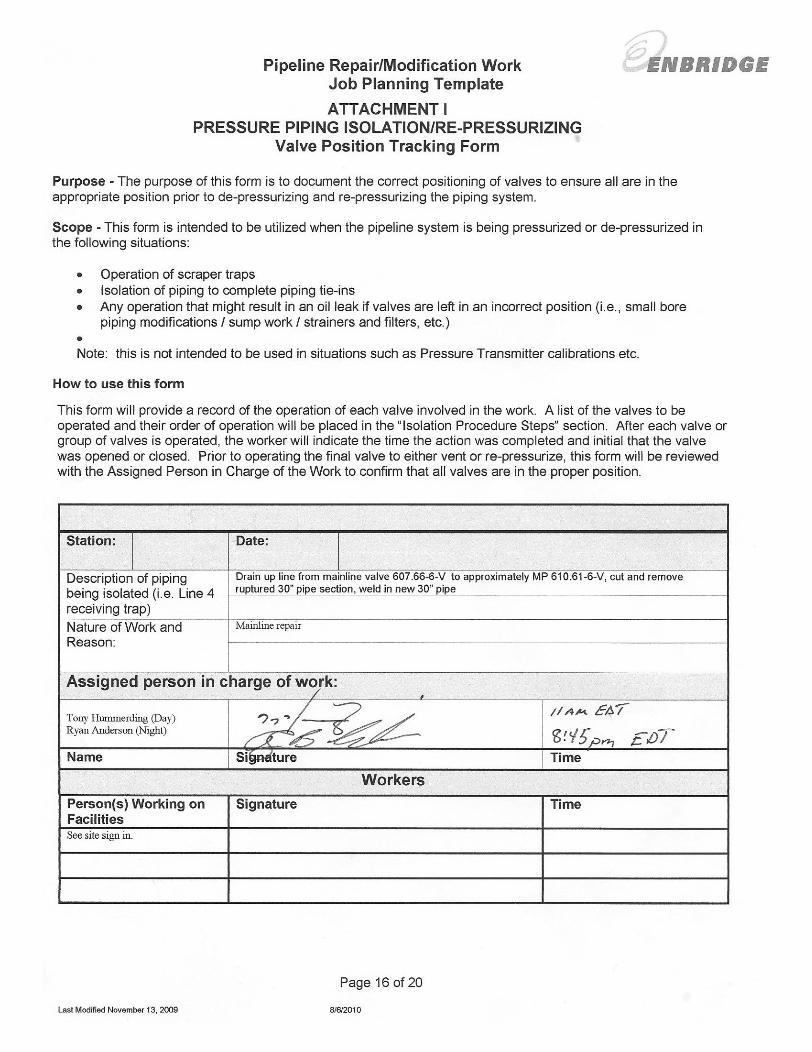
Pipeline Repair/Modification Work Job Planning Template
Page 1 of 20
Last Modified November 13, 2009 8/6/2010
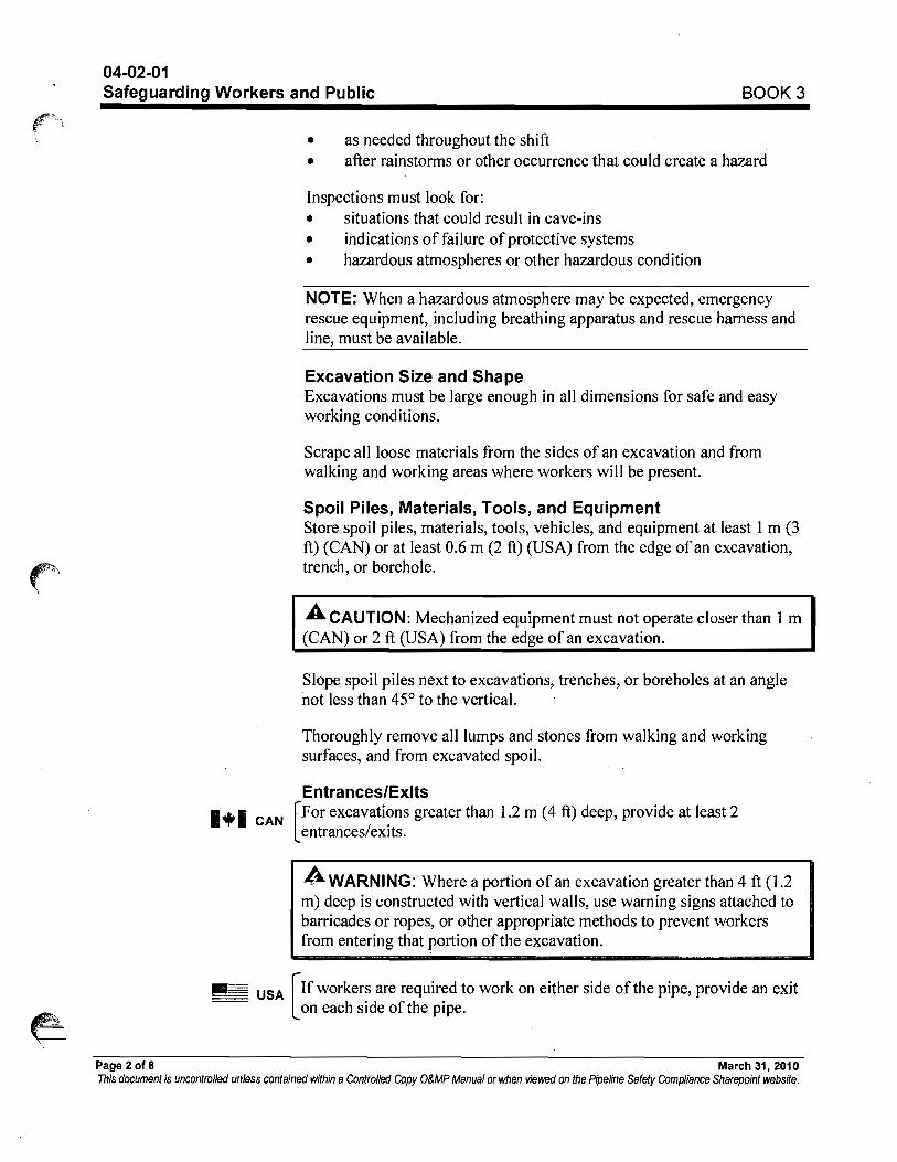
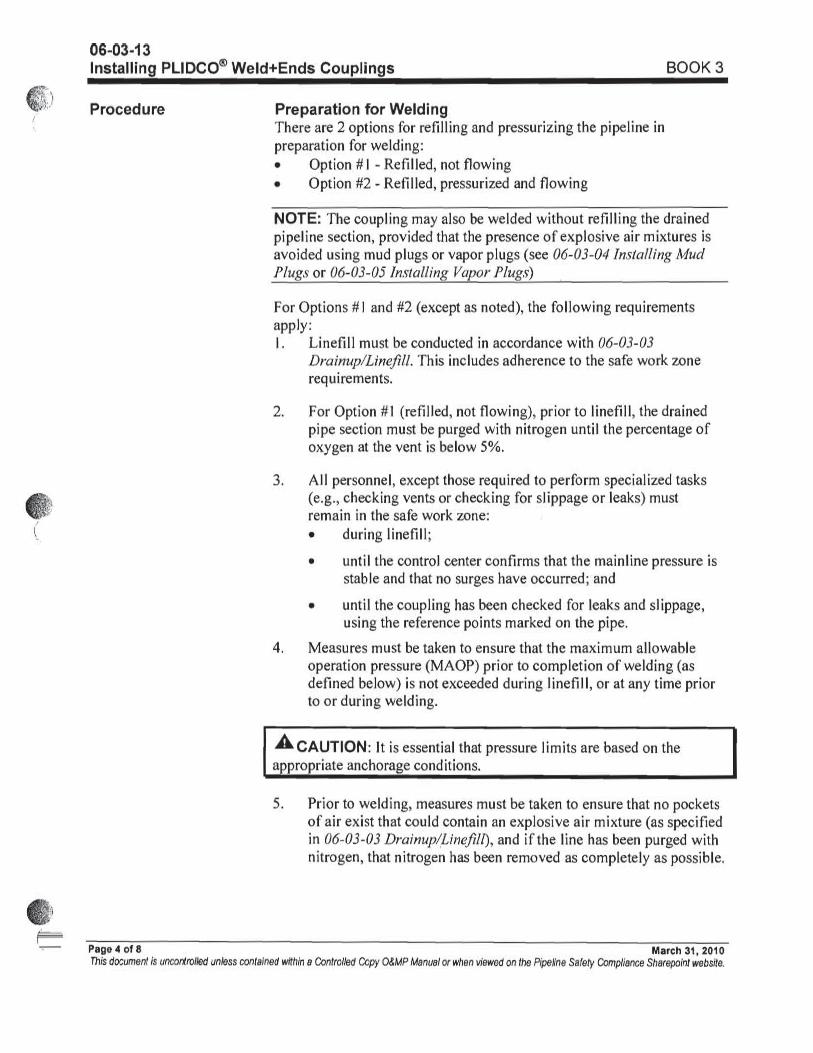
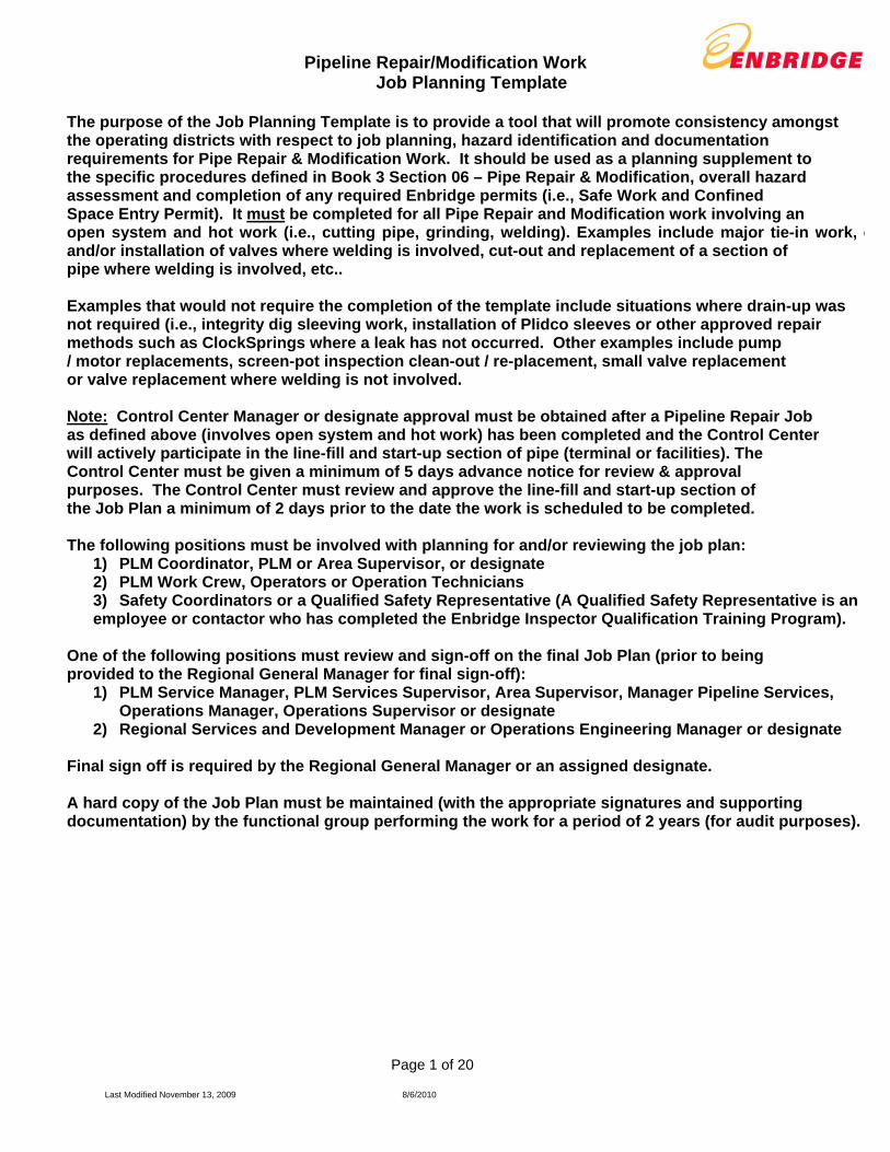
The purpose of the Job Planning Template is to provide a tool that will promote consistency amongst the operating districts with respect to job planning, hazard identification and documentation requirements for Pipe Repair & Modification Work. It should be used as a planning supplement to the specific procedures defined in Book 3 Section 06 – Pipe Repair & Modification, overall hazard assessment and completion of any required Enbridge permits (i.e., Safe Work and Confined Space Entry Permit). It must be completed for all Pipe Repair and Modification work involving an open system and hot work (i.e., cutting pipe, grinding, welding). Examples include major tie-in work, cand/or installation of valves where welding is involved, cut-out and replacement of a section of pipe where welding is involved, etc.. Examples that would not require the completion of the template include situations where drain-up was not required (i.e., integrity dig sleeving work, installation of Plidco sleeves or other approved repair methods such as ClockSprings where a leak has not occurred. Other examples include pump / motor replacements, screen-pot inspection clean-out / re-placement, small valve replacement or valve replacement where welding is not involved. Note: Control Center Manager or designate approval must be obtained after a Pipeline Repair Job as defined above (involves open system and hot work) has been completed and the Control Center will actively participate in the line-fill and start-up section of pipe (terminal or facilities). The Control Center must be given a minimum of 5 days advance notice for review & approval purposes. The Control Center must review and approve the line-fill and start-up section of the Job Plan a minimum of 2 days prior to the date the work is scheduled to be completed. The following positions must be involved with planning for and/or reviewing the job plan:
1) PLM Coordinator, PLM or Area Supervisor, or designate 2) PLM Work Crew, Operators or Operation Technicians 3) Safety Coordinators or a Qualified Safety Representative (A Qualified Safety Representative is an employee or contactor who has completed the Enbridge Inspector Qualification Training Program).
One of the following positions must review and sign-off on the final Job Plan (prior to being provided to the Regional General Manager for final sign-off):
1) PLM Service Manager, PLM Services Supervisor, Area Supervisor, Manager Pipeline Services, Operations Manager, Operations Supervisor or designate
2) Regional Services and Development Manager or Operations Engineering Manager or designate Final sign off is required by the Regional General Manager or an assigned designate. A hard copy of the Job Plan must be maintained (with the appropriate signatures and supporting documentation) by the functional group performing the work for a period of 2 years (for audit purposes).

Pipeline Repair/Modification Work Job Planning Template
Page 2 of 20
Last Modified November 13, 2009 8/6/2010
JOB PLAN:
New Plan Revised Plan
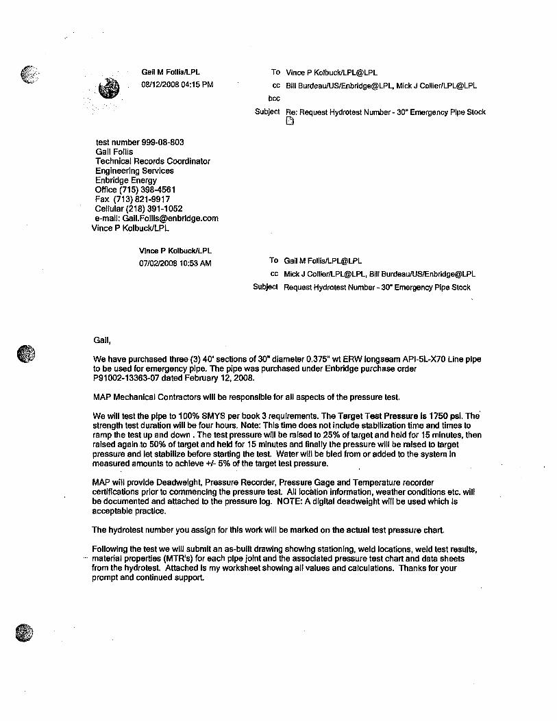
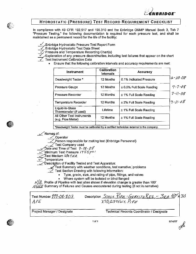
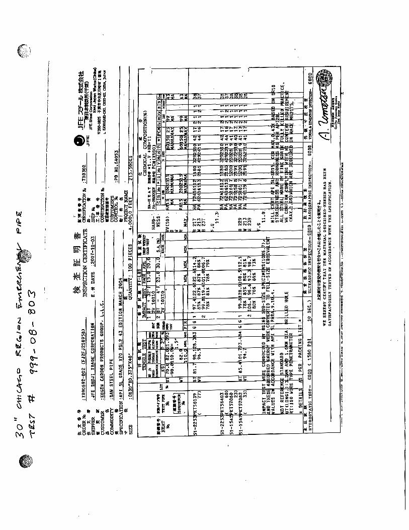
Asset/Location (MP): Line 6B MP 608 Pipe Cut Out --- Butt Weld Repair
Prepared by: John Pechin & Bill Palmer Date Prepared: 08/05/10
AFE Number: 91153SC10124
Est. Start Date: 7/30/10
Est. Completion Date: 8/08/10
Job Objective: Repair section of pipe on Line 6B that ruptured.
Job Scope: Drain up line 6 section, cut and remove 30” pipe section, weld in new 30” pipe
MANPOWER LISTING AND CONTACT INFORMATION: (Identify affected personnel and ensure necessary communications are complete prior to starting job)
Contact Name Contact Phone # N/A
Regional Manager or designate Garry Worone 832-331-6652
PLM Services Manager, Manager Pipeline Services, Operations Manager or designate
David Hodgins (Day) Adam Erickson (Night)
918-285-1132 218-393-6405
Regional Services & Development Manager, Operations Engineering Manager or designate
Dean Rawson 219-381-5350
PLM Supervisor, Operations or Area Supervisor or designate
Steve Sleaver / (Days) Ryan Anderson (Nights)
920-723-8824 920-988-7931
PLM Coordinator, Project Coordinator, Operations Coordinator or designate
Tony Hommerding(Days) 218-393-1308
Regional Engineer, Operations Engineer or designate
John Pechin(Nights) Bill Palmer (Days)
218-393-3180 218-390-7901
Safety Coordinator or Qualified Safety Representative
Jason Palmer (Day) Lamar Kelley (Night)
918-285-6297 218-391-5341
Pipeline Control Contact Control Center Line 6B Richard Folkema
800-379-4781 Extension 8896 780-420-8285
Contractors:
1.Roberts, Support labor as needed Kris Kemper (Day) Greg Fisher (Night)
765-524-5253 765-620-0301
2.MN Limited, General Contractor, Welders, Labor and support materials and services and equipment
Mike Hyke (Day) Dave Voeltz (Night)
612-810-5714 763-478-1245
3. Code Red, Confined Space Rescue
Mike Accroman (Day) Alfredo Sida (Night)
219-506-3523 219-588-0874
Other: (First Responders) 1. Police 911
2. Fire 911
3. Ambulance 911
4. Hospital (include directions to nearest hospital).
East on Division Dr.. North on Old 27 East on 94-BR North on Madason.
269-781-4271

Pipeline Repair/Modification Work Job Planning Template
Page 3 of 20
Last Modified November 13, 2009 8/6/2010
Planning Items / Considerations - General Yes No N/A1. Has the availability of the General Manager or designate been confirmed for the dates of the planned work?
2. Has the availability of the Safety Coordinator or Qualified Safety Representative for the dates of the planned
work been confirmed? 3. If a Qualified Safety Representative has been assigned, has he or she received the Enbridge Inspector
Qualification training? 4. Have the members of the Job Planning Team been identified (see above for planning team members)?
5. Have all applicable O&M Procedures been identified and reviewed by the planning team?
6. Does the required work require engineering analysis or other department technical support (i.e., Pipeline /
Facilities Integrity)? If so, has the support been arranged for? 7. If any conditions in the O&M Procedures cannot be met has a variance been granted / approved by the
Regional Manager or designate? 8. Have all necessary regulatory permitting requirements been arranged for / obtained?
9. If applicable, have any necessary landowner arrangements been arranged for by the ROW Agent?
10. Have the necessary materials and replacement components been identified and availability confirmed, as
listed in the Job Safety Analysis? 11. Have the members of the work crew been actively involved with planning for the work activity including
identifying hazards and risk mitigation strategies (should be included in performing what-if scenario analysis)?
12. Have Employees performing pipeline safety related/OQ /PBT tasks met training and OQ/PBT requirements for
each of the tasks they will be involved in (including appropriate documentation)?
13. Have Contractors performing pipeline safety related/OQ /PBT tasks met training and OQ/PBT requirements for
each of the tasks they will be involved in (including appropriate documentation)?
14. Are appropriate procedures in place for those employees/contractors who are not fully qualified but will be
involved and/or participate in the completion of a pipeline safety related/OQ/PBT task(s) as follows?
Use of Non-Qualified Individuals
To facilitate pipeline repair work, non-qualified individuals may perform pipeline safety related/OQ/PBT tasks
when directed and observed by an OQ/PBT qualified individual who will ensure immediate corrective action is
taken when necessary. Qualified individuals overseeing non-qualified workers are responsible for the correct
and safe performance of the covered task(s).
Span of Control Ratio
Non-qualified workers may be used with the ratio not to exceed two non-qualified workers to one qualified
worker. Factors that may reduce this ratio, and should be considered by the qualified individual(s), are
interferences such as noise, visual obstructions, weather or job site conditions that make it more difficult for an
individual to observe others.
15. Do all replacement components (pipe, motors, pumps, etc.) meet or exceed the design maximum operating
pressure (see Book 3 Section 06-02-01) and / or regulatory requirements? 16. If used pipeline equipment and components are being utilized, has it been confirmed they have been properly
relieved of any trapped pressure and/or hazardous materials and are in proper working condition? 17. If a Plidco Sleeve or Weld Plus Ends are going to be used, has the overall condition including the quality of the
seals been verified? 18. Has all Enbridge equipment that will be used to carry-out the work been identified and checked to ensure it is
in proper working order (i.e., stopple equipment, pipe saws, etc.)? 19. Has all 3rd party equipment that will be used on the job been checked to verify it is in compliance with
regulatory standards/requirements (i.e., cranes, booms, etc)? (As Used.) 20. Has any necessary 3rd party equipment been properly arranged for?
21. Has all necessary PPE been identified including any special PPE requirements (i.e., gas monitoring
equipment, respirators, gloves, etc.)? 22. Has the PPE been verified to be in good working condition?
Pipeline Repair/Modification Work Job Planning Template
Page 4 of 20
Last Modified November 13, 2009 8/6/2010
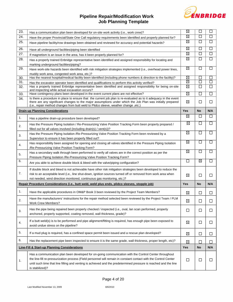
23. Has a communication plan been developed for on-site work activity (i.e., work crew)?
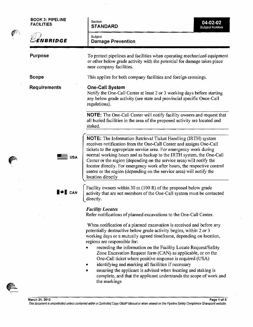
24. Have the proper Provincial/State One Call regulatory requirements been identified and properly planned for?
25. Have pipeline facility/row drawings been obtained and reviewed for accuracy and potential hazards?
26. Have all underground facilities/piping been identified
27. If magnetism is an issue in the area, has it been properly planned for?
28. Has a properly trained Enbridge representative been identified and assigned responsibility for locating and
marking underground facilities/piping? 29. Have work-site hazards been identified with risk mitigation strategies implemented (i.e., overhead power lines,
muddy work area, congested work area, etc.)? 30. Has the nearest hospital/medical facility been identified (including phone numbers & direction to the facility)?
31. Has the excavator operator been identified and qualifications to perform this activity verified? 32. Has a properly trained Enbridge representative been identified and assigned responsibility for being on-site
and inspecting while actual excavation occurs? 33. Have contingency plans been developed in the event current plans are not effective?
34. Is there a procedure in place to ensure that the current job plan is re-evaluated as to it adequacy in the event there are any significant changes to the major assumptions under which the Job Plan was initially prepared (i.e., repair method changes from butt weld to Plidco sleeve, weather change ,etc.)
Drain-up Planning Considerations Yes No N/A
1. Has a pipeline drain-up procedure been developed?
2. Has the Pressure Piping Isolation / Re-Pressurizing Valve Position Tracking Form been properly prepared /
filled out for all valves involved (including drain(s) / vent(s))?
3. Has the Pressure Piping Isolation /Re-Pressurizing Valve Position Tracking Form been reviewed by a
Supervisor to ensure it has been properly filled out?
4. Has responsibility been assigned for opening and closing all valves identified in the Pressure Piping Isolation
/Re-Pressurizing Valve Position Tracking Form?
5. Has a secondary walk through been performed to verify all valves are in the correct position as per the
Pressure Piping Isolation /Re-Pressurizing Valve Position Tracking Form? 6.
Are you able to achieve double block & bleed with the valve/piping configuration?
7. If double block and bleed is not achievable have other risk mitigation strategies been developed to reduce the
risk to an acceptable level (i.e., line shut-down, ignition sources turned off or removed from work area when
not needed, wind direction monitored, continuous gas monitoring, etc.)?
Repair Procedure Considerations (i.e., butt weld, weld plus ends, plidco sleeves, stopple job) Yes No N/A
1. Have the applicable procedures in OM&P Book 3 been reviewed by the Project Team Members?
2. Have the manufacturers’ instructions for the repair method selected been reviewed by the Project Team / PLM
Work Crew Members?
3. Has the pipe being repaired been properly checked / inspected (i.e., oval, lan scan performed, properly
anchored, properly supported, coating removed, wall thickness, grade)?
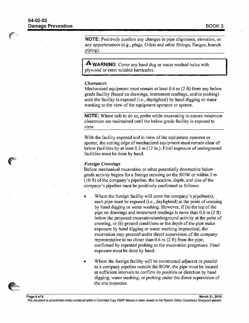
4. If a butt weld(s) is to be performed and pipe alignment/fitting is required, has enough pipe been exposed to
avoid undue stress on the pipeline?
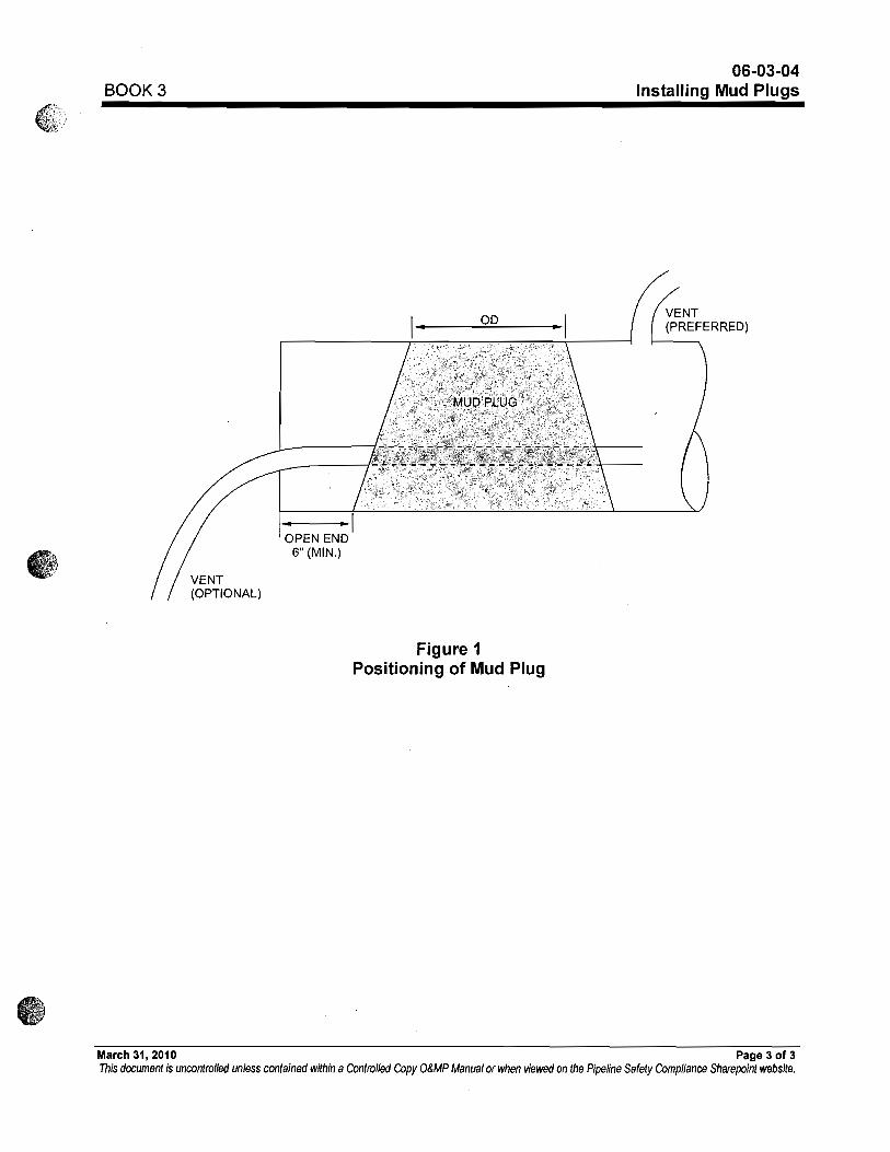
5. If a mud plug is required, has a confined space permit been issued and a rescue plan developed?
6. Has the replacement pipe been inspected to ensure it is the same grade, wall thickness, proper length, etc)?
Line-Fill & Start-up Planning Considerations Yes No N/A
1.
Has a communication plan been developed for on-going communication with the Control Center throughout
the line-fill re-pressurization process (Field personnel will remain in constant contact with the Control Center
until such time that line filling and venting is achieved and the predetermined pressure is reached and the line
is stabilized)?
Pipeline Repair/Modification Work Job Planning Template
Page 5 of 20
Last Modified November 13, 2009 8/6/2010
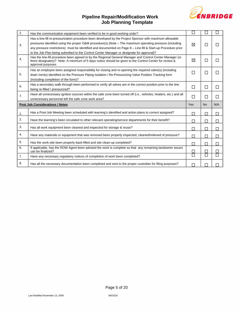
2. Has the communication equipment been verified to be in good working order?
3.
Has a line-fill re-pressurization procedure been developed by the Project Sponsor with maximum allowable
pressures identified using the proper O&M procedure(s) (Note – The maximum operating pressure (including
any pressure restrictions) must be identified and documented on Page 8 – Line-fill & Start-up Procedure prior
to the Job Plan being submitted to the Control Center Manager or designate for approval)?
4.
Has the line-fill procedure been agreed to by the Regional General Manager and Control Center Manager (or there designates)? Note: A minimum of 5 days notice should be given to the Control Center for review & approval purposes.
5. Has an employee been assigned responsibility for closing and re-opening the required valve(s) (including
drain /vents) identified on the Pressure Piping Isolation / Re-Pressurizing Valve Position Tracking form
(including completion of the form)?
6. Has a secondary walk through been performed to verify all valves are in the correct position prior to the line
being re-filled / pressurized?
7. Have all unnecessary ignition sources within the safe zone been turned off (i.e., vehicles, heaters, etc.) and all
unnecessary personnel left the safe zone work area?
Post Job Considerations / Notes Yes No N/A
1. Has a Post-Job Meeting been scheduled with learning’s identified and action plans to correct assigned?
2. Have the learning’s been circulated to other relevant operating/service departments for their benefit?
3. Has all work equipment been cleaned and inspected for storage & reuse?
4. Have any materials or equipment that was removed been properly inspected, cleaned/relieved of pressure?
5. Has the work-site been properly back-filled and site clean-up completed?
6.
If applicable, has the ROW Agent been advised the work is complete so that any remaining landowner issues can be finalized?
7. Have any necessary regulatory notices of completion of work been completed?
8. Has all the necessary documentation been completed and sent to the proper custodian for filing purposes?

Pipeline Repair/Modification Work Job Planning Template
Page 6 of 20
Last Modified November 13, 2009 8/6/2010
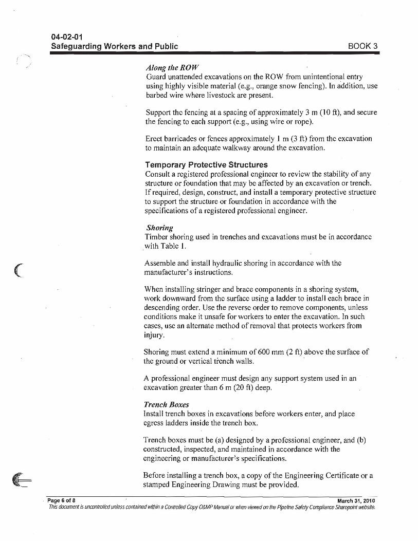
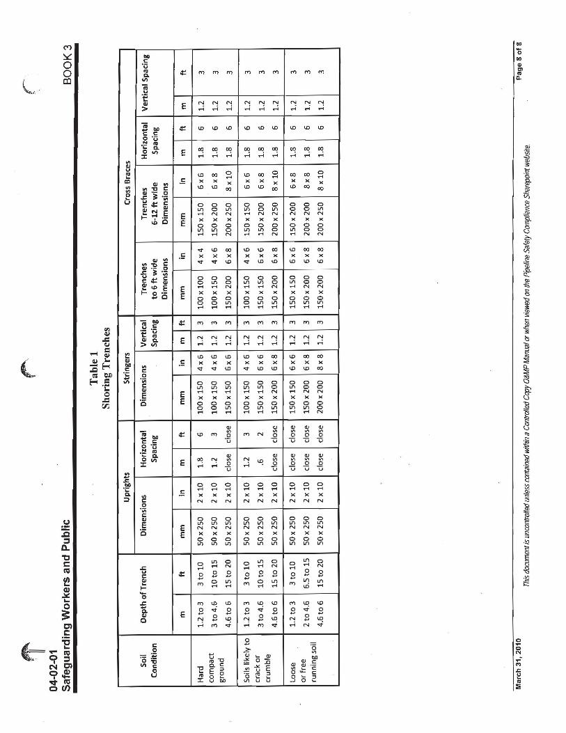
Pre-Planning – Additional Items/Notes (Specify relevant OM&P sections – mandatory)
1.
Drain is currently in progress due to the rupture. Site cleanup and preparation is ongoing.
2.
Notify Pipeline Integrity, NTSB, PHSMA and EPA 1 hour prior to commencement of excavation. Notify Tom Zimmerman (780-660-1916) to notify Michigan DNRE onsite officer Bill Ford 1 hour prior to commencement of cutting of pipe.
3.
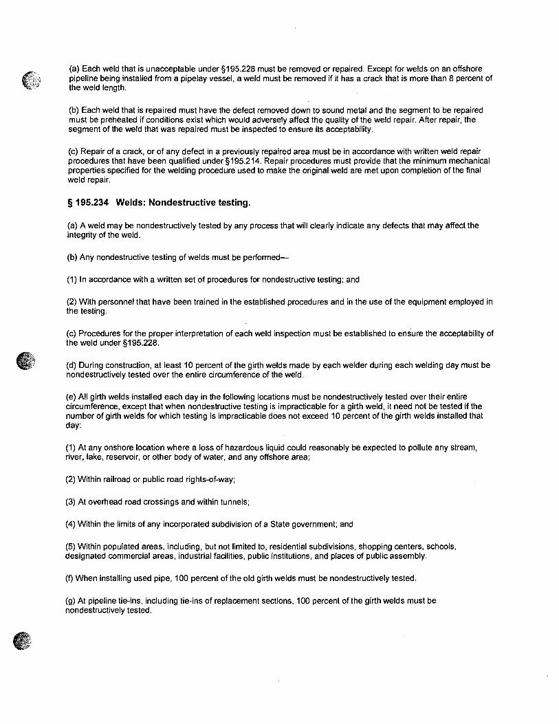
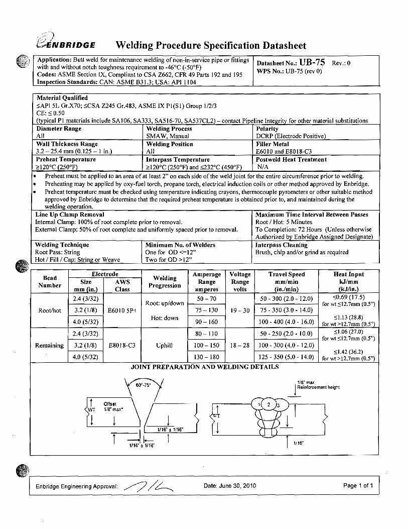
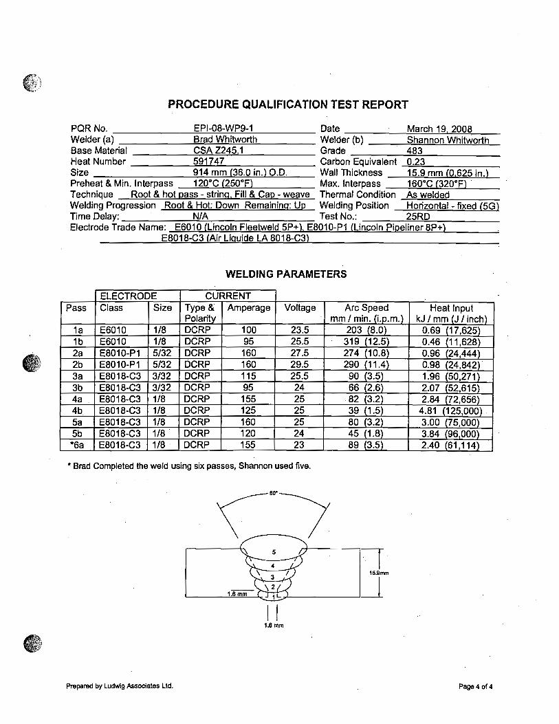
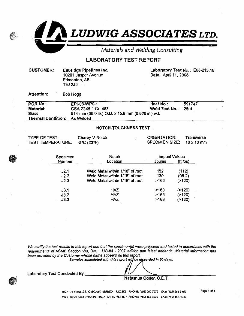
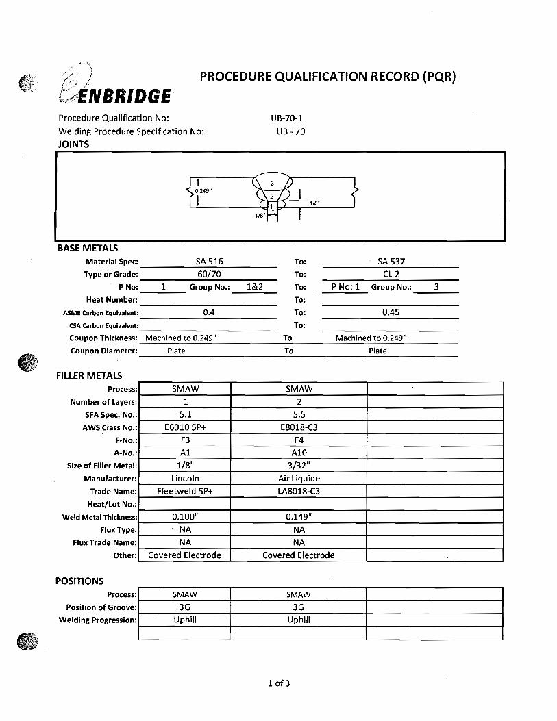
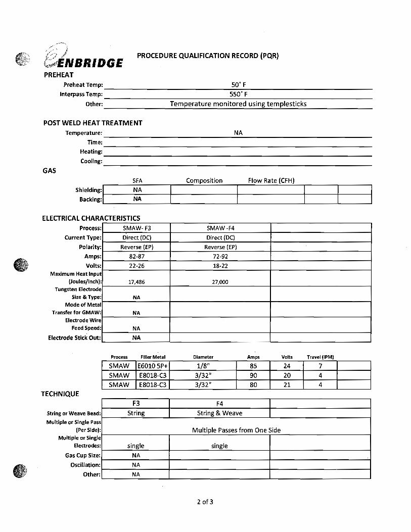
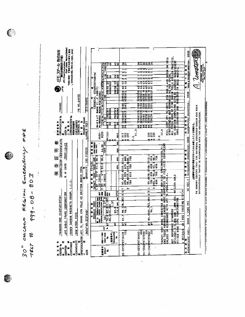
Repair will entail removal of existing ruptured joint of pipe and installation of approximately 46’ feet of new pipe. (30” diameter, 0.375” wall thickness, 5L-X70). The replacement pipe is joining to API-5L X-52 pipe and the thicker replacement pipe will require appropriate transitioning by grinding. New pipe will be installed using Enbridge butt weld procedures UB-75.
4.
After new pipe section is installed the bottom of the pipe shall be adequately backfilled (prior to line fill) to prevent movement / settlement per Book 3, 04-02-03 requirements.
5.
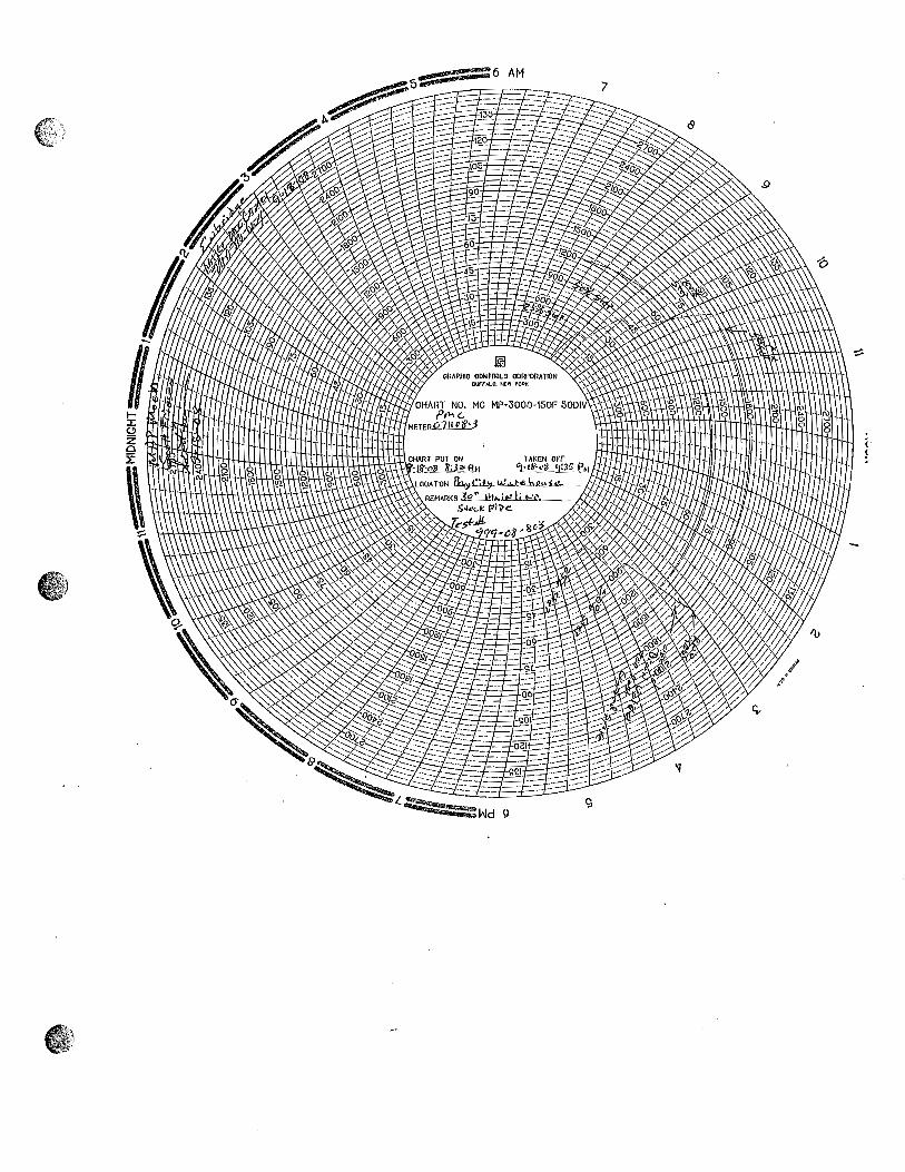
Line fill will be completed using crude available upstream of leak site via mainline pump GT-U-3 at Griffith. Fill valve to be 607.66-6-V.
6.
Venting of air for linefill will be done via multiple 2” fitting installations located on the new pipe section and existing pipe ends. In addition an existing high point 2” fitting located upstream of the rupture location can be used. Vent points will be connected to a vacuum truck during the venting process.
7.
Only essential personnel shall be within the 100’ hot zone in venting location. All ignition sources will be shut off in the 100’ hot zone.
8.
Updates with CCO will be provided every 2 hours or as needed. GM or designate onsite will be responsible for providing the updates.
9.
Primary Isolation Valves 607.66-6-V and 610.61-6-V are to be bleed prior to cutting to ensure valve seats are holding. Bleeding is to be done periodically throughout repair process following cuts to tie in. Isolation Points Upstream to Downstream in Order: 599.43-6-V 607.63-6-V 6-SSV-1 6-SDV-1 607.66-6-V Rupture 610.61-6-V 611.00-6-V 620.66-6-V Double Block and Bleed Upstream of rupture: Continuous monitoring of isolated section upstream of valve 607.66-6-V will be achieved via pressure transmitter PT-2D located at Marshall Station. Double Block and Bleed Downstream of rupture: Double Block and Bleed downstream of the rupture location cannot be achieved. To mitigate risk of valve leakage at 610.61-6-V an additional 2” TDW vent fitting is required for monitoring liquid.
10.
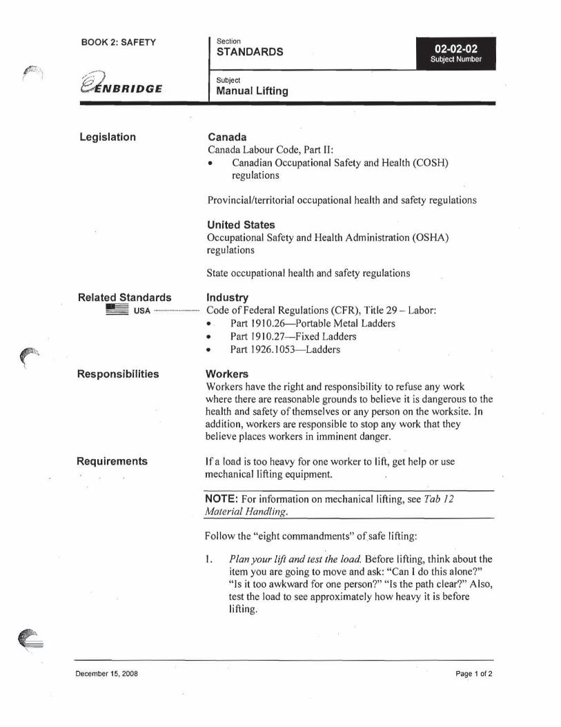
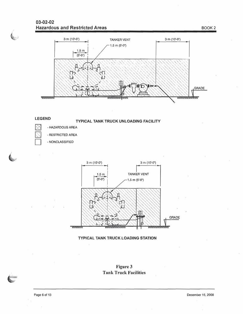
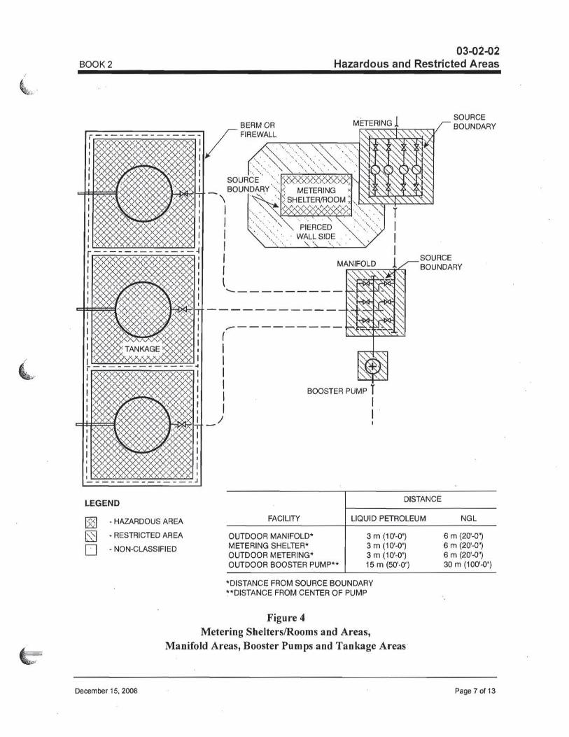
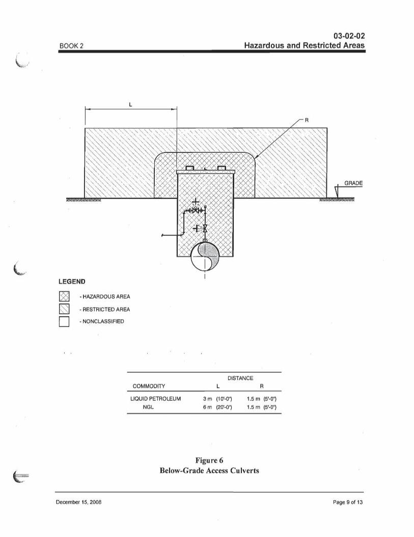
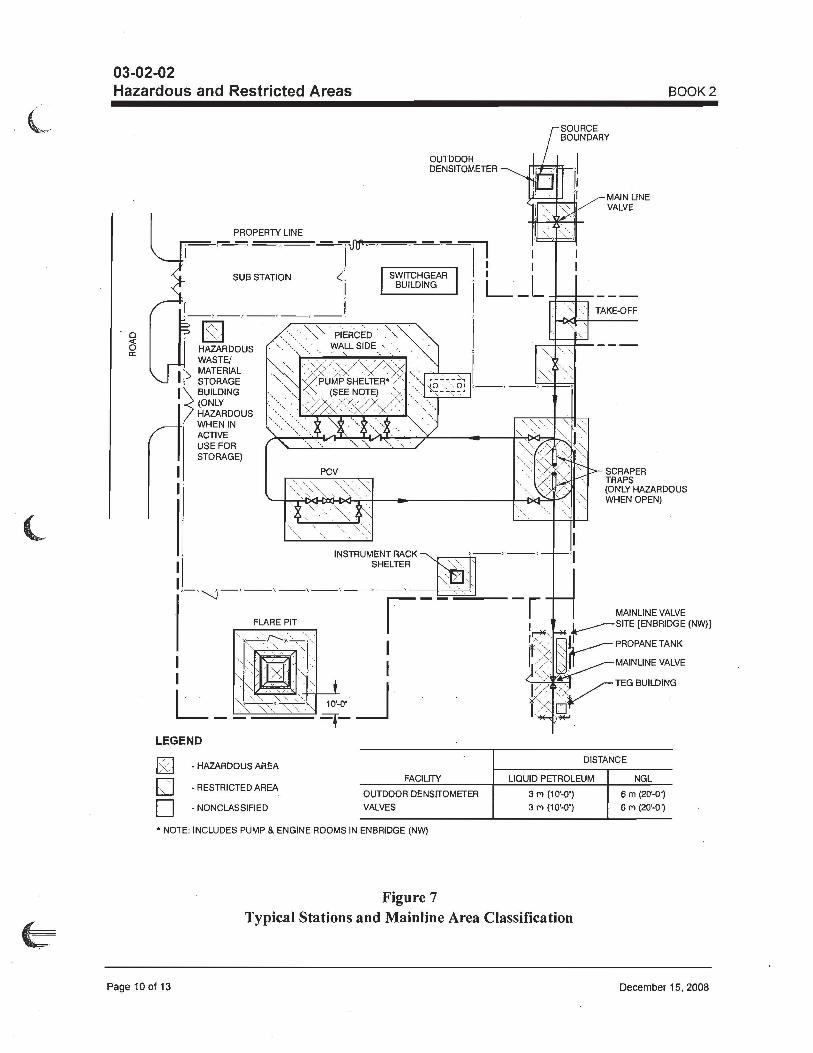
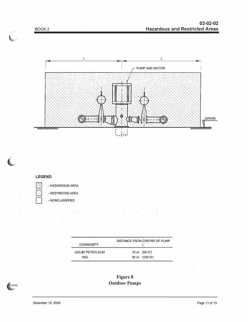
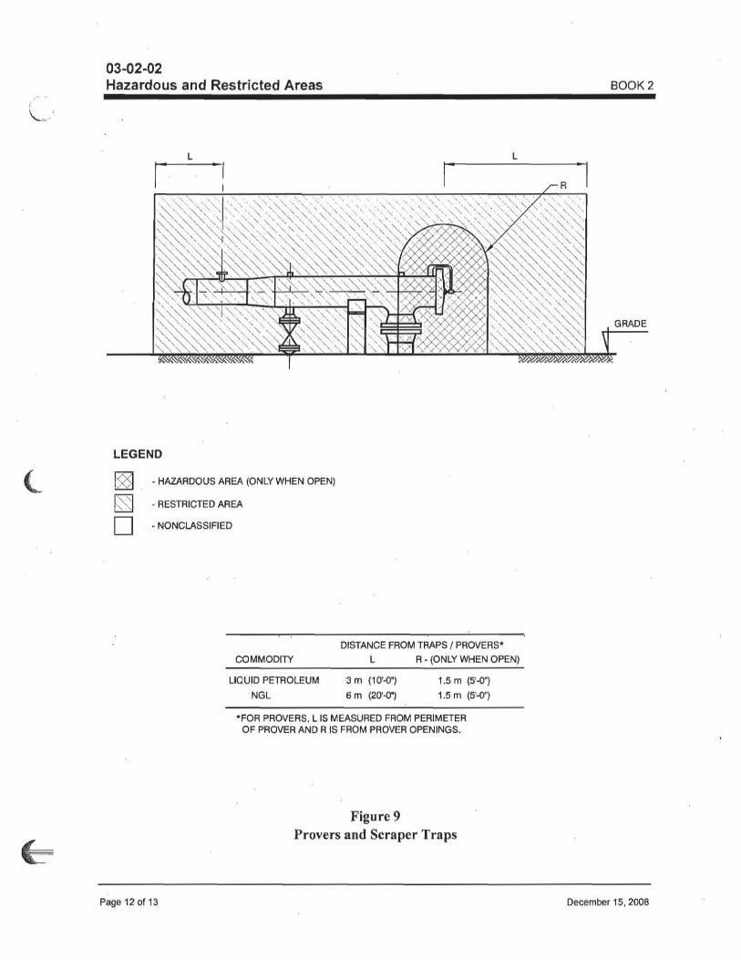
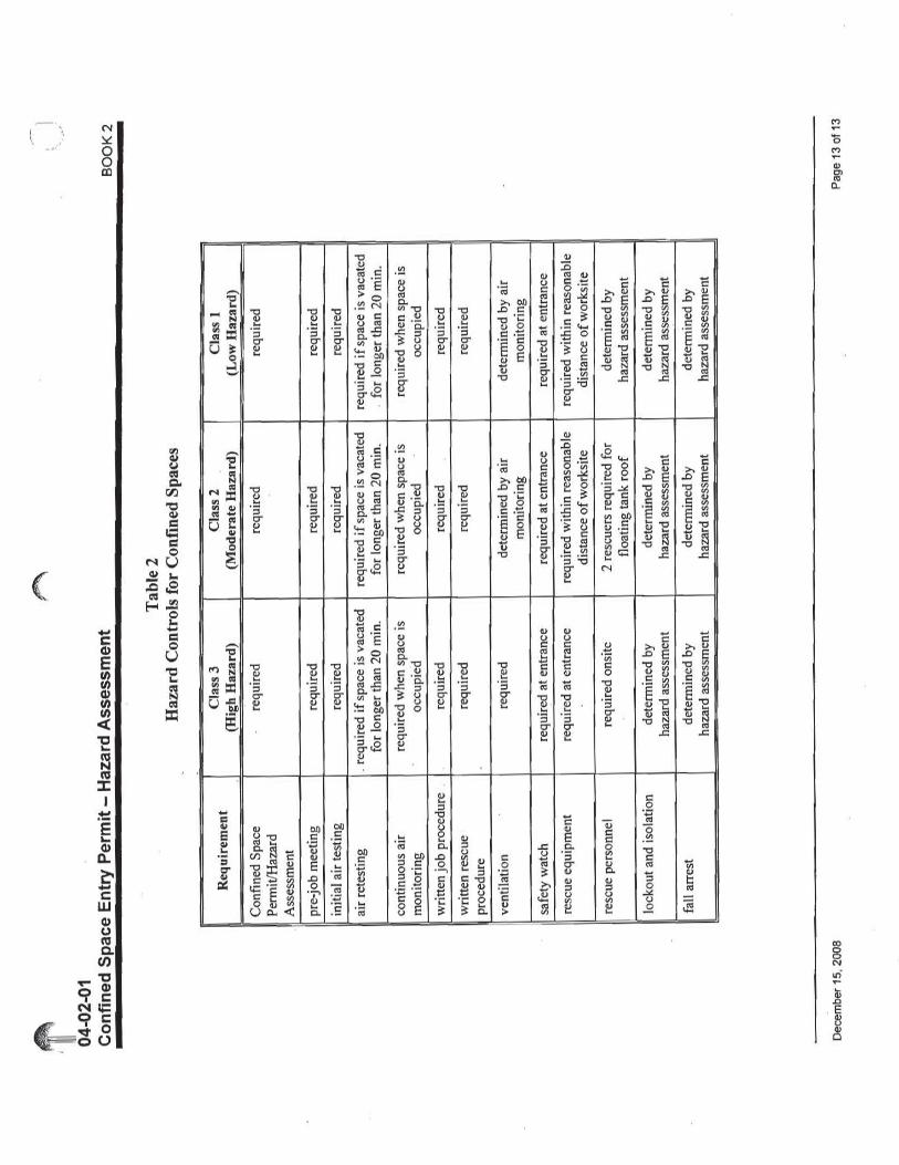
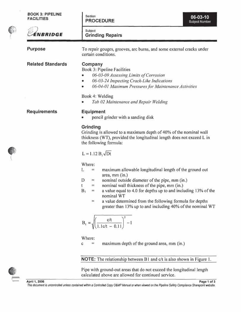
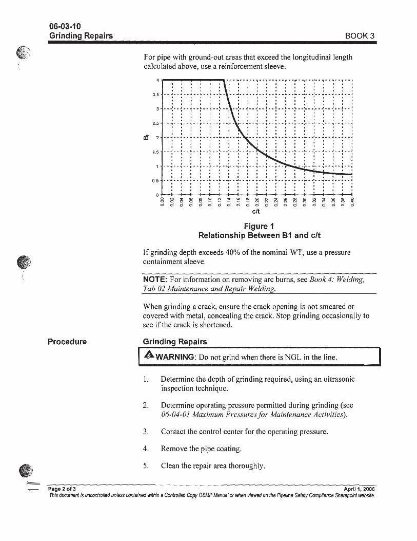
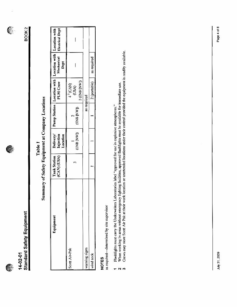
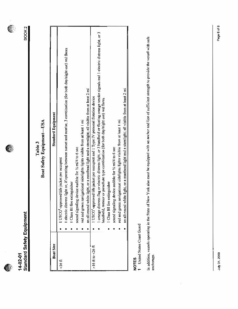
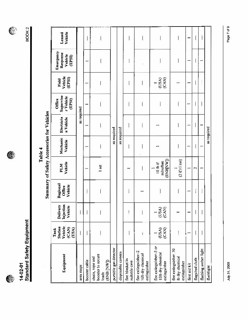
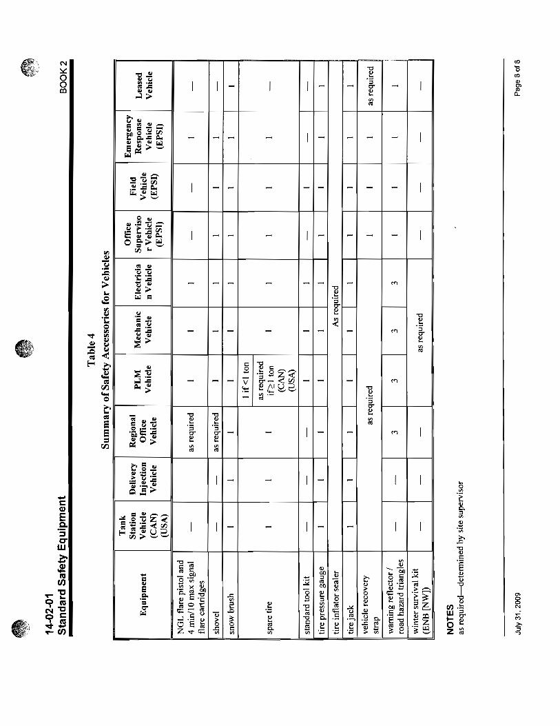
Relevant OM&P sections: Book 2: 02-02-02, 02-02-04, 03-02-01, 03-02-02, 04-02-01, 05-02-02, 06-03-01 & 02, Tab 7, Tab 9, 11-02-01 through 03 & 07, Tab 12, 13-02-01 through 10, 14-02-01 through 04 Book 3: 04-02-02, 06-03-02 through 05, 06-03-10, 06-03-17, 06-03-21
11. Contingency Planning Materials & Equipment– 120’ of 30” X 0.375” W.T. API 5L X 70 (Marshall PLM stock Onsite) 120’ of 30” X 0.375” W.T. API 5L X 70 (Bay City PLM Stock Onsite) 120’ of 30” X 0.375” W.T. API 5L X 70 (Bay City PLM Stock – Available from Bay City) Two 30” PLIDCO Weld Plus End Couplings (Marshall PLM) Two 30” PLIDCO Split Sleeves (Marshall PLM) Field Bend Machine Hydro testing Equipment Manpower & Resources – The job schedule will be evaluated periodically. Currently the location will be staffed 24 hours, 12 hour shifts from 7 am to 7pm.
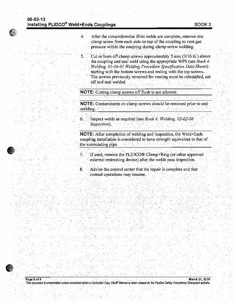
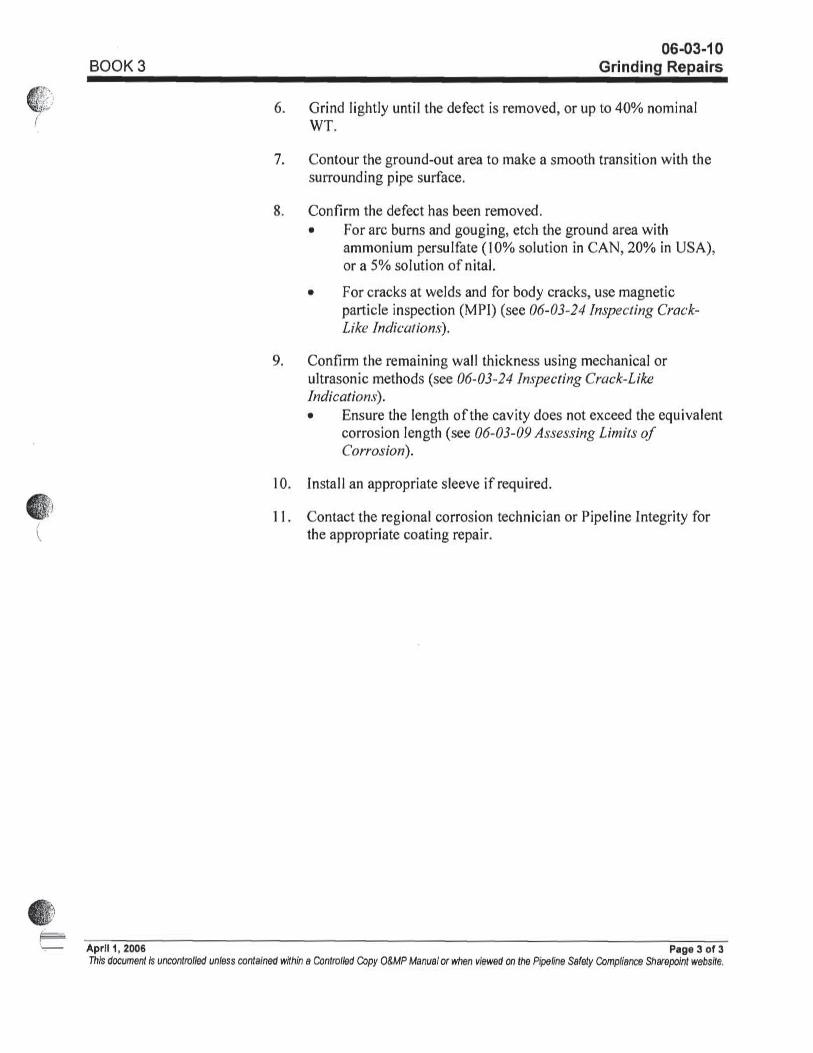
12. Line Up Concerns – It is preferred to perform a butt weld on both ends of the new pipe section to be installed. If lineup is not acceptable an alternative method of joining the pipe will be completed (either weld plus end will be installed per Enbridge O&MP 06-03-13 Installing Plidco Weld Plus Ends Couplings or split repair sleeve).

Pipeline Repair/Modification Work Job Planning Template
Page 7 of 20
Last Modified November 13, 2009 8/6/2010
Pipe Investigation Process
1.
No excavation, pipe removal or inspection can occur unless NTSB, EPA, MDNRE and PHMSA representatives have been notified.
2.
This Investigation Process Procedure has been developed in concert with the NTSB, PHMSA and Enbridge Pipeline Integrity Representatives.
3.
Follow all aspects of Book 3, 06-03-22 – Removing Pipe for Investigation – Review in detail at start of each shift. During excavation and dewatering, ensure that drains and hoses do not contact the rupture surfaces.
4.
Enbridge representatives will document the excavation, pipe examination, pipe removal and pipe installation.
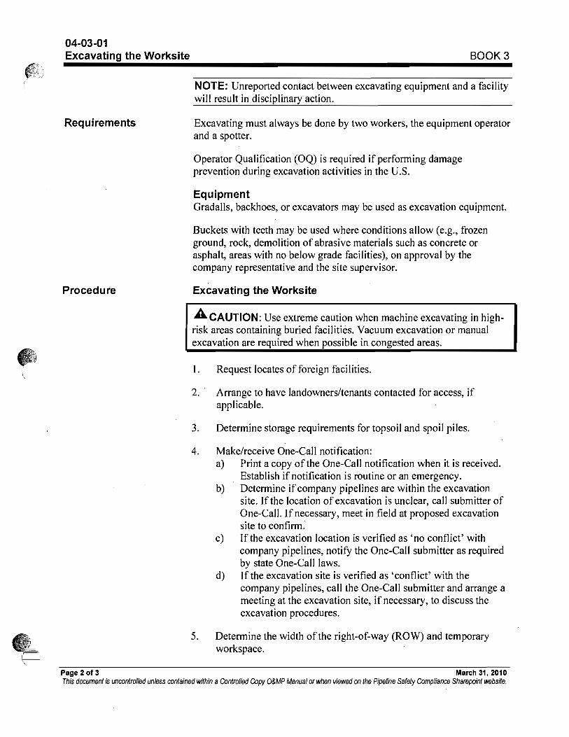
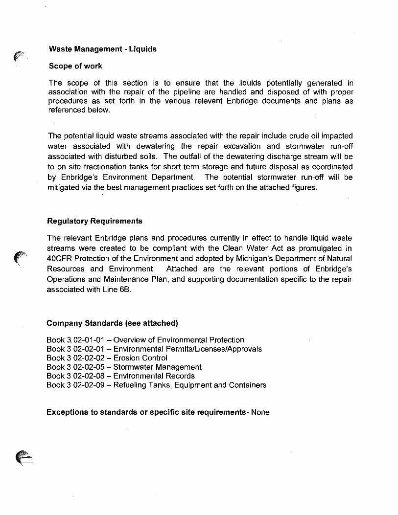
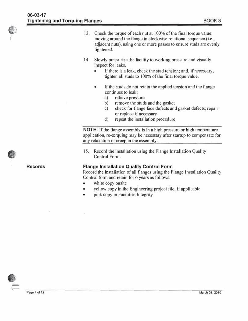
5. Expose and excavate approximately 180 ft of pipe in accordance with Enbridge O&MP Manual Book 3 04-03-01. The excavation will extend from upstream of girth weld 217710 to downstream of girth weld 217740.
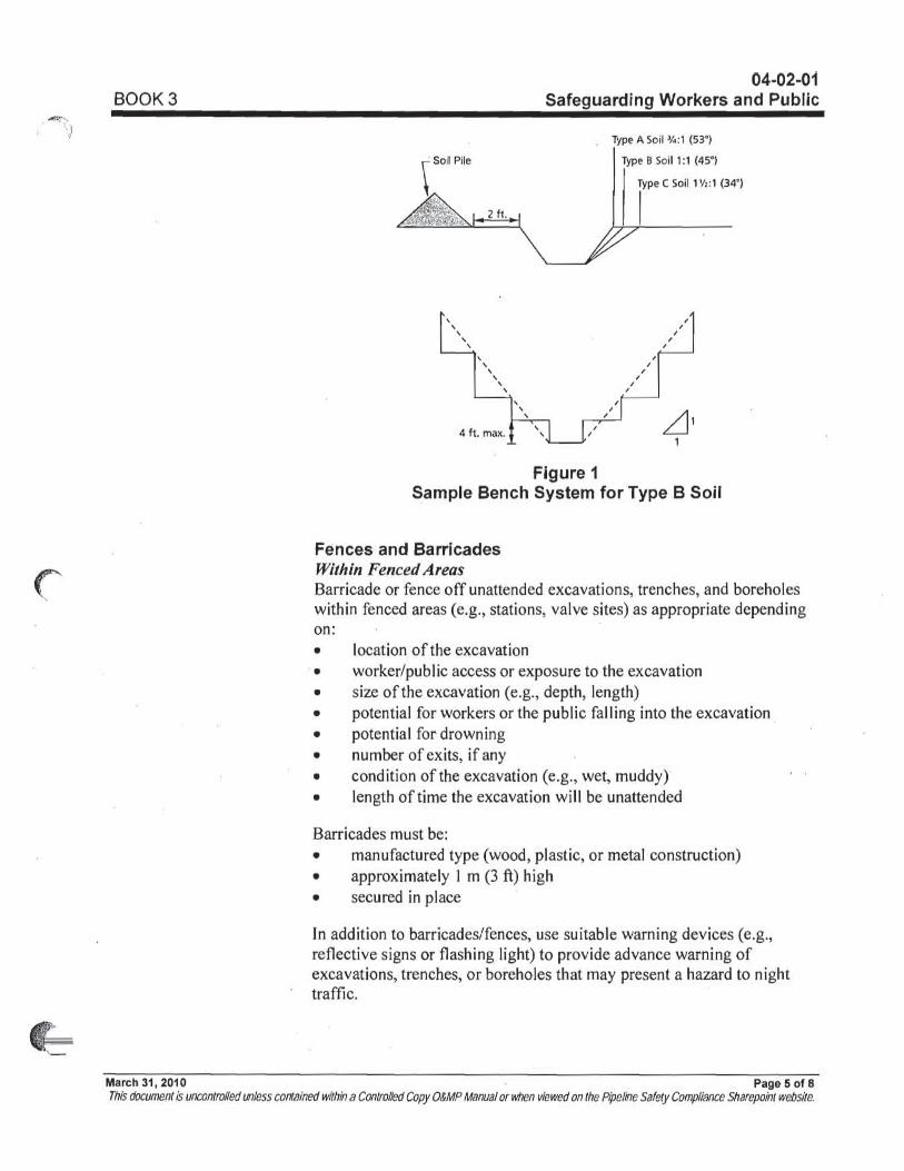
5. Prepare ditch for safe access by repair and inspection personnel. Ensure cribbing supports pipe every 20’ per the O&MP 04-02-03.
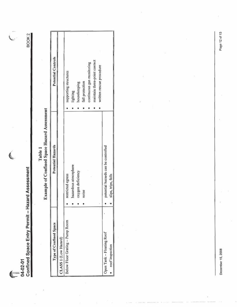
6. Enbridge Pipeline Integrity locates and verifies girth welds 217720 and 217730. See Figure 1 for details. 7. Conduct an elevation profile survey of the top of the exposed pipe by taking elevation readings at a maximum interval of 5
feet. 8. The first cut will be at least 4 feet downstream of girth weld 217730 or 3 feet from the end of the rupture, whichever is
longer. Actual position of cold cut location will be approved by the NTSB prior to starting cutting operations. 9. The drain up will be completed out of this cut per Enbridge procedures. A Wachs saw will be used to cut into the pipe
from the top to allow a controlled liquid flow into a trough. As the liquid level drops, the saw will cut deeper until it is all the way through. The liquid in the trough will be transferred into a vacuum truck for disposal off site.
10. Any pipe movement after this cut has been completed will be measured by onsite surveyors, photographed and documented by Enbridge Pipeline Integrity.
11.
Prior to removal, visually inspect and photograph the pipe rupture by Enbridge Pipeline Integrity. The photos will be labeled as follows: Enbridge Line 6B MP 608.375 Flow Direction 12:00 Position
12. Onsite surveyors will measure and record GPS coordinates of beginning and end of failure location in Latitude, Longitude, six decimal place accuracy Measure distance from U/S 2” TOR fitting to upstream end of rupture.
13. Cut the pipe at least 4 feet upstream of girth weld 217720. Actual position of cold cut location will be approved by the NTSB prior to starting cutting operations.
14.
Remove the cut out pipe section and place in a safe location on site. During pipe removal attempt to keep all evidence (pipe material, coating etc.) in as-found condition as much as reasonably possible
15. The NTSB Pipe Specimen will made up by cutting the removed pipe section as follows:
a. Cut the pipe joint 19 feet downstream of girth weld 217720 where there are no ILI indications. Actual position of cold cut location will be approved by the NTSB prior to starting cutting operations.
b. Trim the ends as required by NTSB.
16. The NTSB Pipe Specimen shall be marked as follows: Enbridge Line 6B MP 608.375 Each segment will have a unique identifier Label Flow Direction Label 12:00 Position Label long seam orientation Label pipeline station footage Label GPS coordinate of failure location in Latitude, Longitude, six decimal place accuracy Label distance from U/S 2” TOR fitting to failure location. Label upstream and downstream girth welds (217720 and 217730) MDNRE and NTSB will also add their own unique markings.
Pipeline Repair/Modification Work Job Planning Template
Page 8 of 20
Last Modified November 13, 2009 8/6/2010
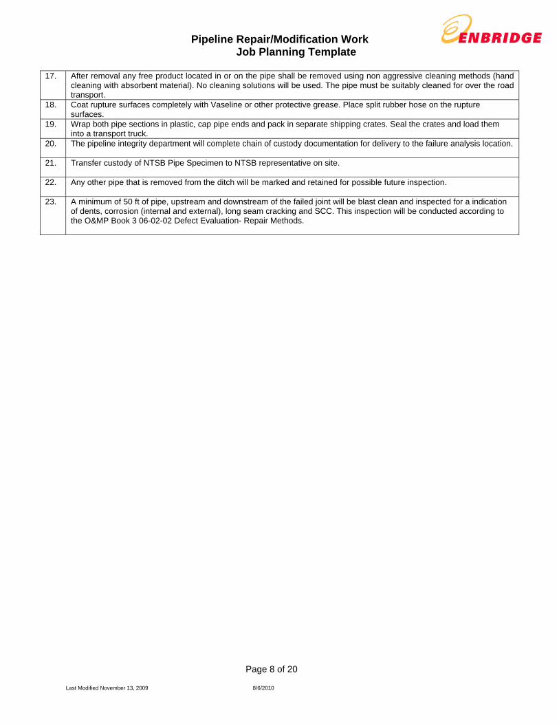
17. After removal any free product located in or on the pipe shall be removed using non aggressive cleaning methods (hand cleaning with absorbent material). No cleaning solutions will be used. The pipe must be suitably cleaned for over the road transport.
18. Coat rupture surfaces completely with Vaseline or other protective grease. Place split rubber hose on the rupture surfaces.
19. Wrap both pipe sections in plastic, cap pipe ends and pack in separate shipping crates. Seal the crates and load them into a transport truck.
20.
The pipeline integrity department will complete chain of custody documentation for delivery to the failure analysis location.
21.
Transfer custody of NTSB Pipe Specimen to NTSB representative on site.
22.
Any other pipe that is removed from the ditch will be marked and retained for possible future inspection.
23.
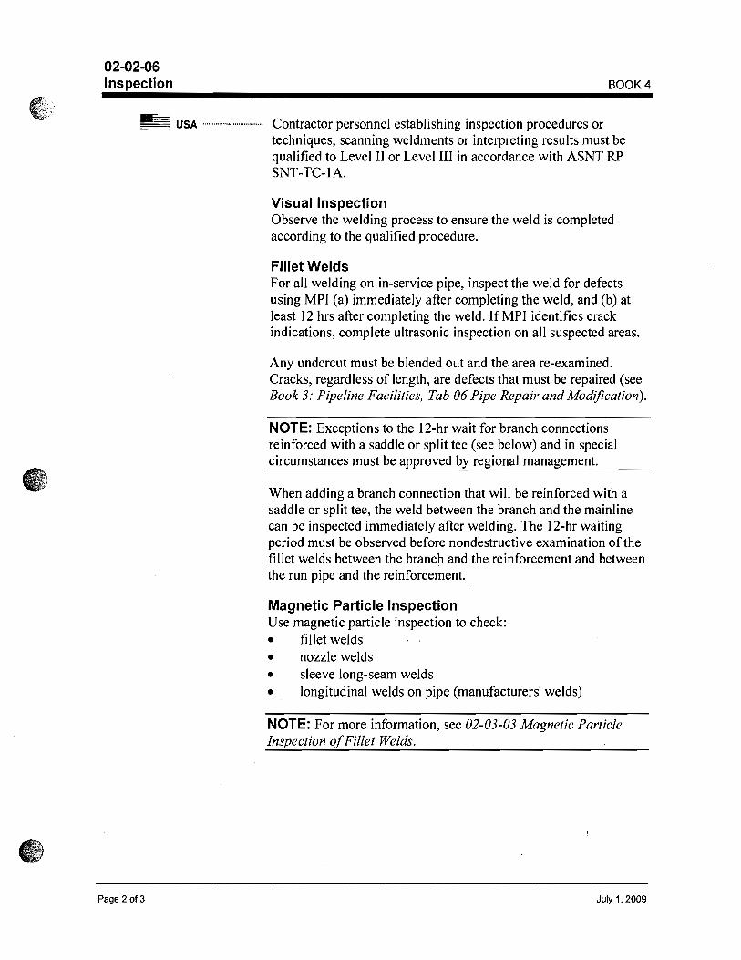
A minimum of 50 ft of pipe, upstream and downstream of the failed joint will be blast clean and inspected for a indication of dents, corrosion (internal and external), long seam cracking and SCC. This inspection will be conducted according to the O&MP Book 3 06-02-02 Defect Evaluation- Repair Methods.

Pipeline Repair/Modification Work Job Planning Template
Page 9 of 20
Last Modified November 13, 2009 8/6/2010
Drain-up Procedure Potential Hazards Hazard Controls
1.
Maintain communication with Edmonton Control Center (1-800-379-4781 Extension 8896) to periodically communicate progress.
2.
Upstream Valves LOTO 599.43-6-V, 607.66-6-V, 6-SDV-1, 6-SSV-1, 607.63-6-V
Missed Energy Source.
Complete the Pressure piping isolation/Re-pressurization Valve Position Tracking Form Book 2 tab 6 Section 06-02-01 & 06-03-01, Isolate and Lockout Electrical sources to Valves, Chain and Lock hand wheels on Valves.
3.
Downstream valves: LOTO 610.61-6-V, 611.00-6-V, 620.66-6-V
Missed Energy Source.
Complete the Pressure piping isolation/Re-pressurization Valve Position Tracking Form Book 2 tab 6 Section 06-02-01 & 06-03-01, Isolate and Lockout Electrical sources to Valves, Chain and Lock hand wheels on Valves.
4.
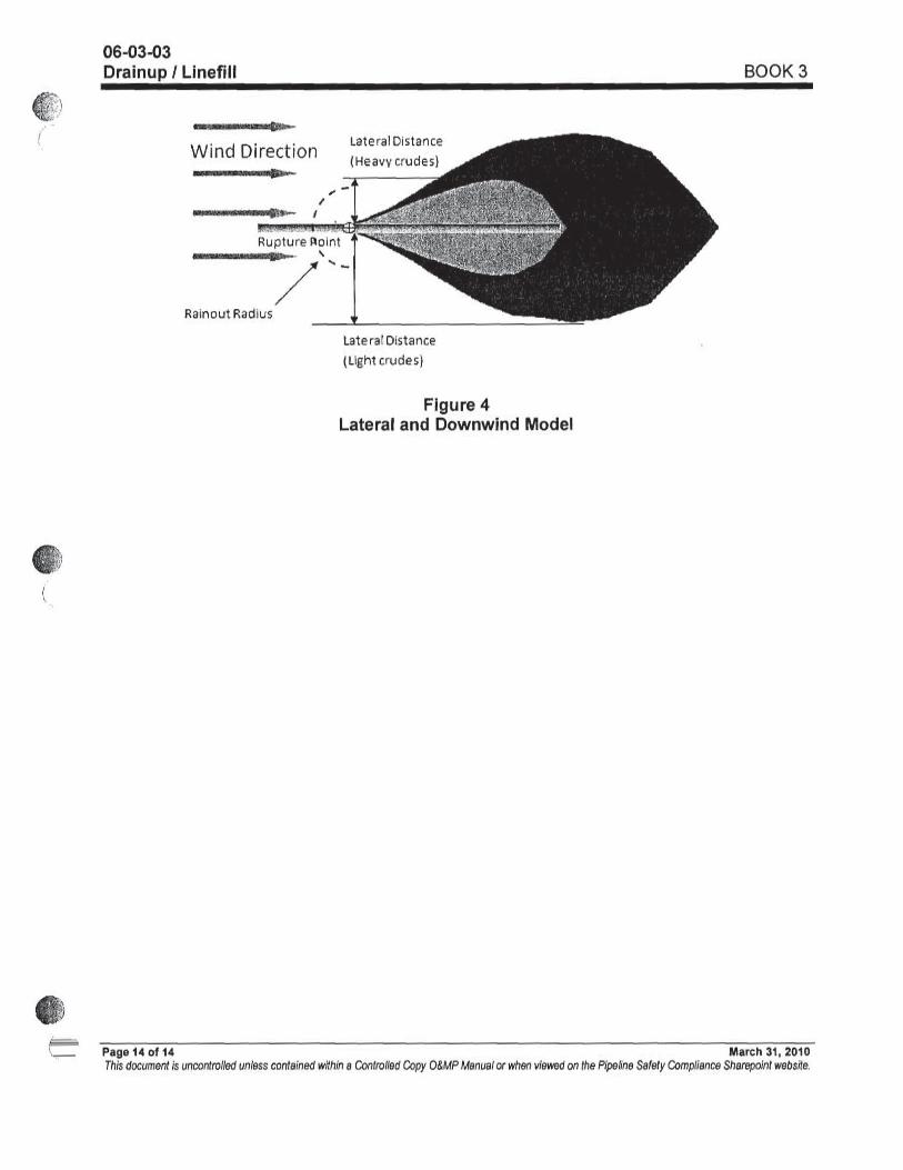
Venting during drain up will done via high point 2” fittings. Fittings are located approximately 125’ upstream of the rupture location. Only essential personnel shall be within the 100’ hot zone in venting location. All ignition sources will be shut off in the 100’ hot zone.
Flammable Vapors, Breathing hazards, Line of fire, Falls, Falling Objects, Working at heights, confined space.
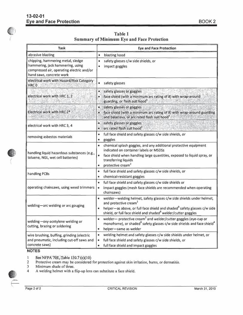
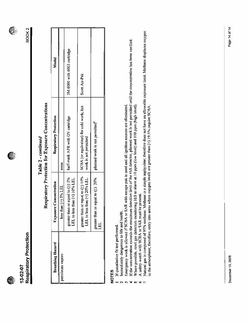
PPE per O&MP Book 2 Tab 13-02-01 through 13-02-10, Gas Monitors; fire Guns, Control Ignition sources
5.
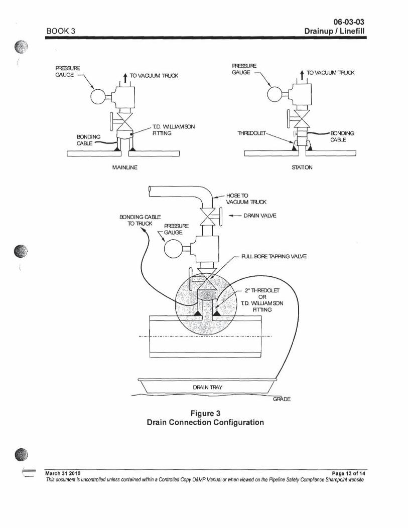
Drain up pipe (refer to Pipe Investigation Section and applicable portion of Book 3, 06-03-03). Once the oil level in the section is at a manageable level, the pipe section is to be partially cut and drained in to tubs.
Flammable Vapors, Breathing hazards, Line of fire, Falls, Falling Objects, Working at heights
PPE per O&MP Book 2 Tab 13-02-01 through 13-02-10, Gas Monitors; fire Guns, Control Ignition sources, Grounding Equipment, Secure hose couplings. Book 2 Tab 14 section 14-02-02
6.
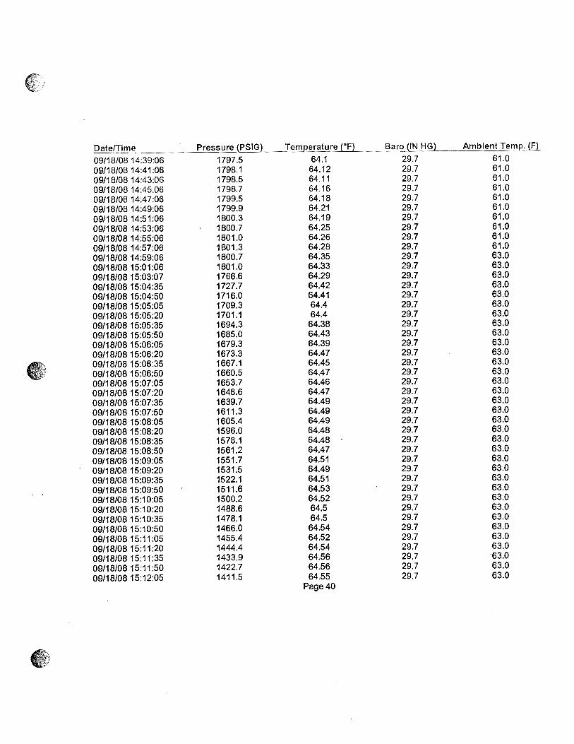
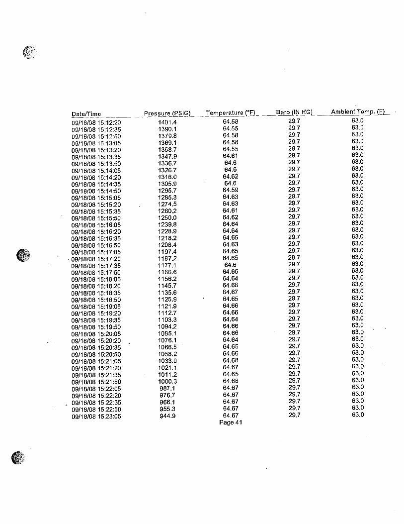
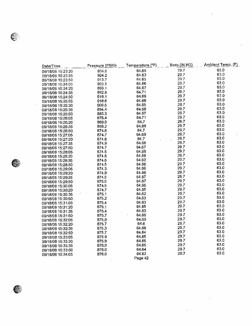
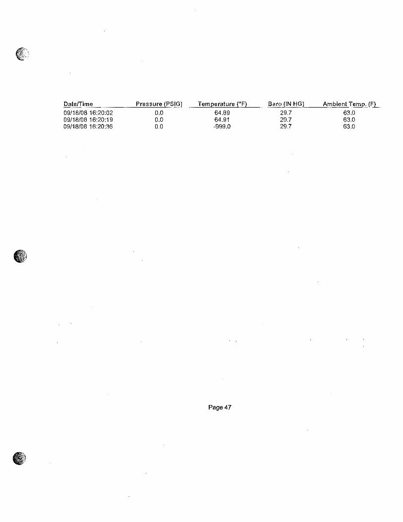
Upstream periodic monitoring double block and bleed pressure monitoring will be performed at Marshall Station pressure transmitter PT-2D. Pressure will be checked and logged every 15 minutes. This task will be performed for the duration of the repair.
Flammable Vapors, Breathing hazards, Line of fire,
PPE per O&MP Book 2 Tab 13-02-01 through 13-02-10, Gas Monitors; Control Ignition sources
7.
Downstream periodic Monitoring for liquid will be performed through a 2” fitting located downstream of the downstream mud plug. Periodic monitoring will be performed every 15 minutes. If oil is present a vac truck with wand will be placed in 2” fitting to remove oil. Additional vents will be installed as required. This task will be performed for the duration of the repair.
Flammable Vapors, Breathing hazards, Line of fire,
PPE per O&MP Book 2 Tab 13-02-01 through 13-02-10, Gas Monitors; Control Ignition sources

Pipeline Repair/Modification Work Job Planning Template
Page 10 of 20
Last Modified November 13, 2009 8/6/2010
JOB SAFETY ANALYSIS: (Define the job steps. Identify and control the potential hazards for each)
Job Steps by Major Category
Job Safety Analysis Potential Hazards Hazard Controls
1.
Prior to performing cuts to pipeline, NTSB evaluation will be performed. Exact location of cuts will be approved by Enbridge Pipeline Integrity in consultation with the NTSB and PHMSA. (See Pipe Investigation Process Section)
2. Cold cut pipe section to be removed. (see Book 3 Tab 06-03-02). Cuts will be made per approved Cut Out Diagram as attached.
Hazardous Vapors, line of fire, flammable vapors, breathing hazards, Air operated equipment, pinch points, Eye hazards
Gas monitors, fire guns, Control Ignition sources, Fire Watch, clips on air lines, ensure fingers are kept out of pinch points, eye protection, respirators, Only vehicles and equipment that are required to perform the work are allowed in the immediate work area. Book 2 tab 14 section 14-02-02, tab 6 section 06-03-21, tab 13
3. Prior to removal of damaged pipe section, ensure residual product is contained. Pipe will be placed in two separate crates per Enbridge Pipeline Integrity and NTSB.
4. Pipe will be removed per the approved contractor Critical Lift Plan with Enbridge Oversight.
Lifting Mark swing radius. Ensure qualified operators. Use tag lines on all objects being lifted.
5..
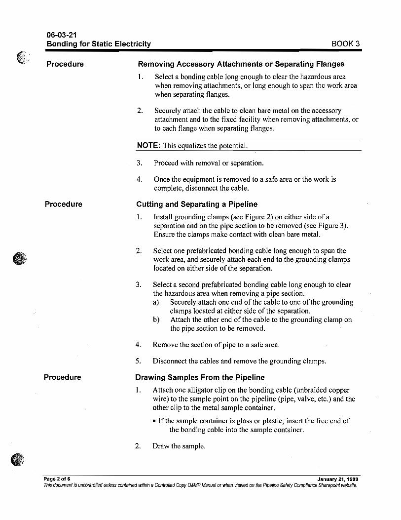
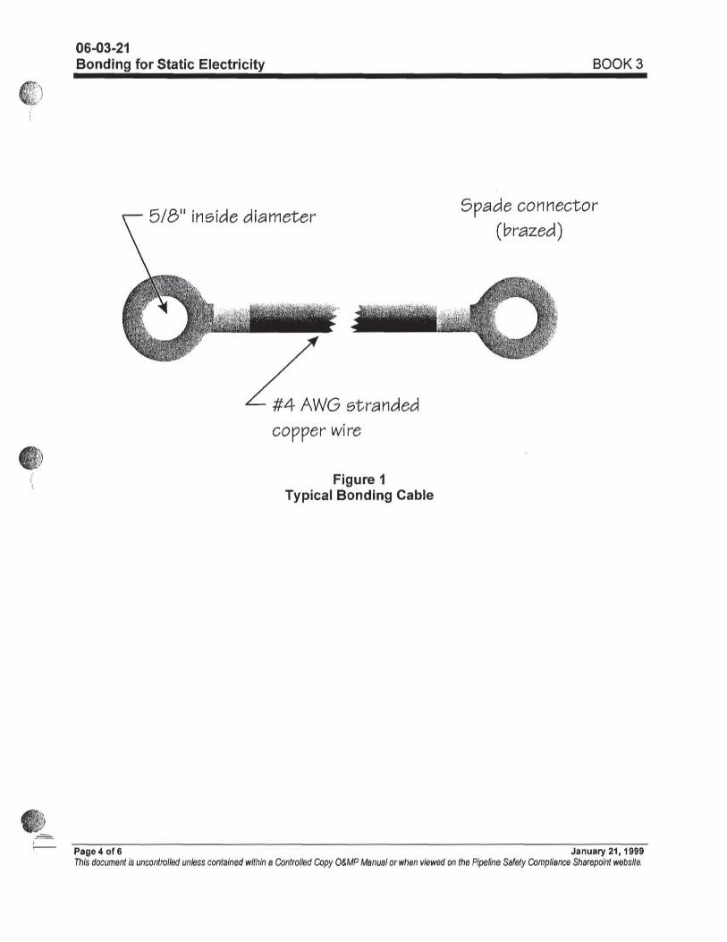
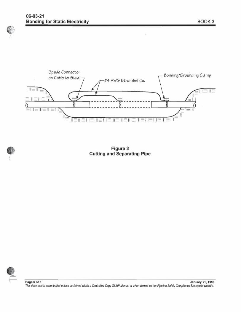
Remove pipe section (see Book 3, 06-03-21, Grounding Pipe for Static Electricity) and place on approved supports (see Book 3, 06-03-22 Removing Pipe for Investigation).
Pinch Points, Lifting Equipment, Hazardous Vapors
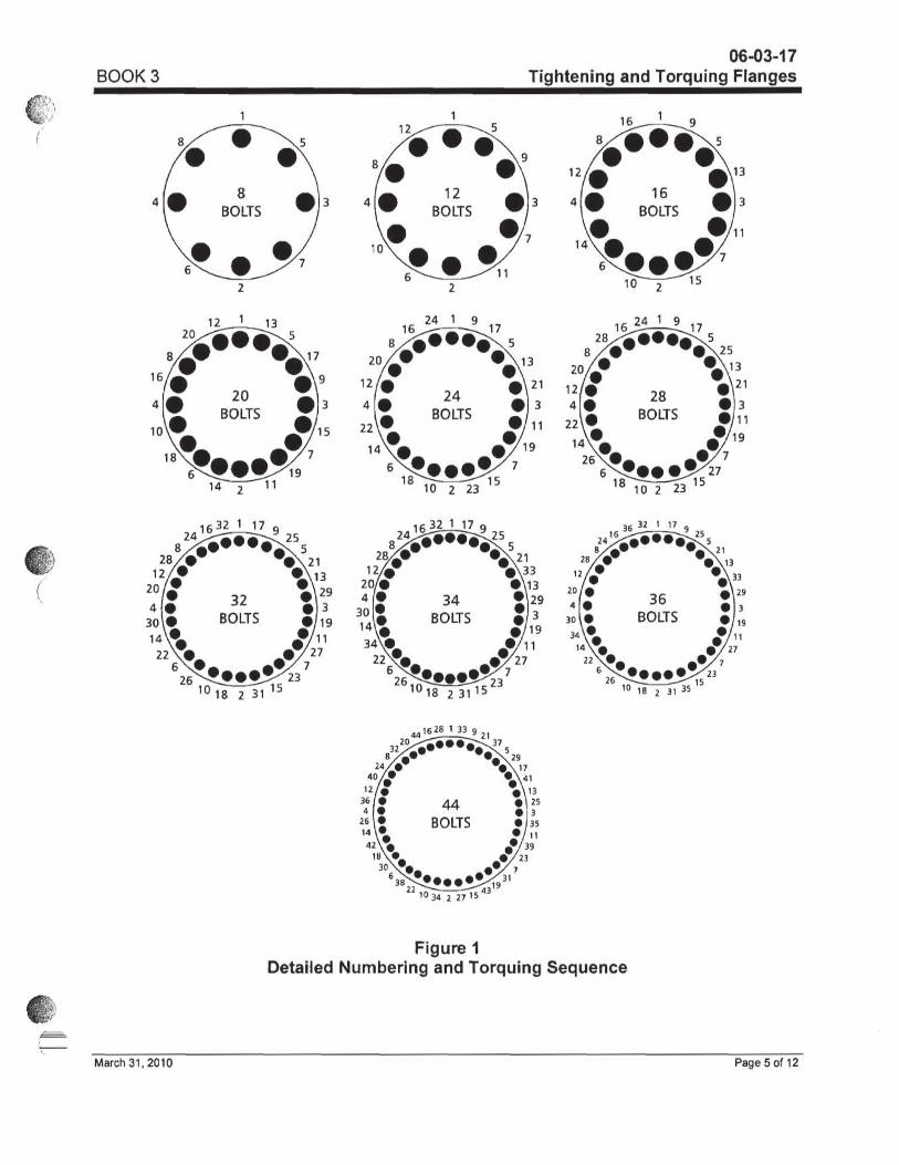
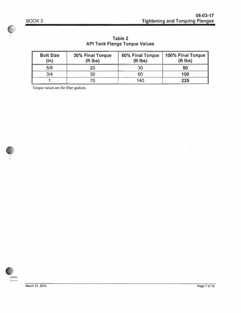
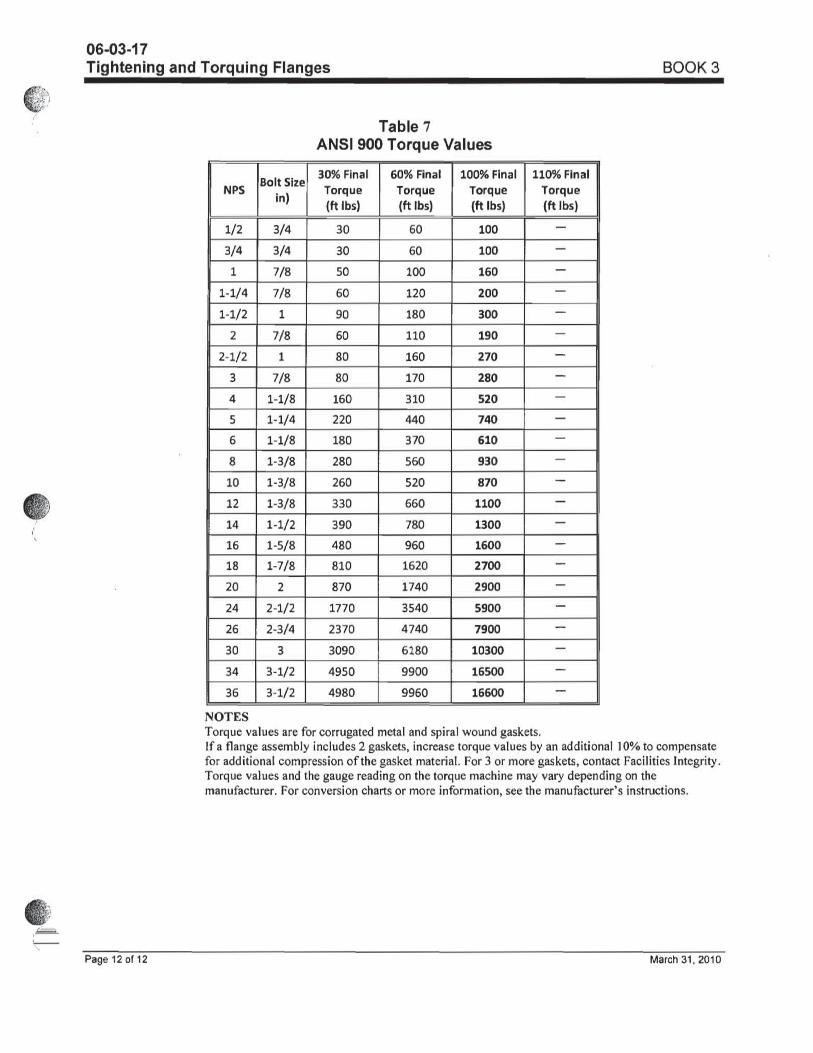
Mark swing radius. Ensure no one places hands/fingers between pipe. Ensure crane operator qualified. Use tag lines on all objects being lifted. Ensure grounding clamps installed on all pieces of pipe. Gas monitors, fire guns, Control Ignition sources, Fire Watch, clips on air lines. Book 2 tab 13, Book 2 tab 12 12-02-01 thru 12-02-03, Book 3 tab 6 06-03-17, tab 6 06-03-21
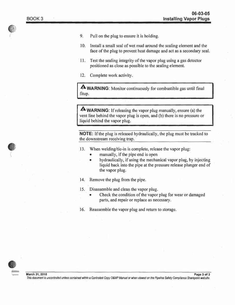
6. Clean inside of pipe at sealing points for foreman plug. (see Book 3, 06-03-05, Installing Vapor Plugs)
Hazardous Vapors, flammable vapors, breathing hazards, Eye hazards
Gas monitors, fire guns, Control Ignition sources, Fire Watch, eye protection, respirators, Only vehicles and equipment that are required to perform the work are allowed in the immediate work area. Book 2 tab 14 section 14-02-02, tab 6 section 06-03-21, tab 13
7.
Install foreman’s plug in each existing pipe end to facilitate. Vent foreman’s plug with hose. Hose should run up the bank, away and down wind. (see Book 3, 06-03-05, installing vapor plugs).
Confined Space, Hazardous Vapors, flammable vapors, breathing hazards, Air operated equipment, pinch points, Eye hazards
Confined Space permit, Confined Space Rescue Plan, Gas monitors, fire guns, Control Ignition sources, Fire Watch, clips on air lines, ensure fingers are kept out of pinch points, eye protection, respirators, Only vehicles and equipment that are required to perform the work are allowed in the immediate work area. Book 2 tab 14 section 14-02-02, tab 6 section 06-03-21, tab 13
8. Prepare piping 50’ upstream of girth weld GWD217720 and 50’ downstream of girth weld GWD217730. This will be done by abrasive blasting.
Confined Space, Hazardous Vapors, flammable vapors, breathing hazards, Air operated equipment, pinch points, Eye hazards
Confined Space permit, Confined Space Rescue Plan, Gas monitors, fire guns, Control Ignition sources, Fire Watch, clips on air lines, ensure fingers are kept out of pinch points, eye protection, respirators, Only vehicles and equipment that are required to perform the work are allowed in the immediate work area. Book 2 tab 14 section 14-02-02, tab 6 section 06-03-21, tab 13
Pipeline Repair/Modification Work Job Planning Template
Page 11 of 20
Last Modified November 13, 2009 8/6/2010
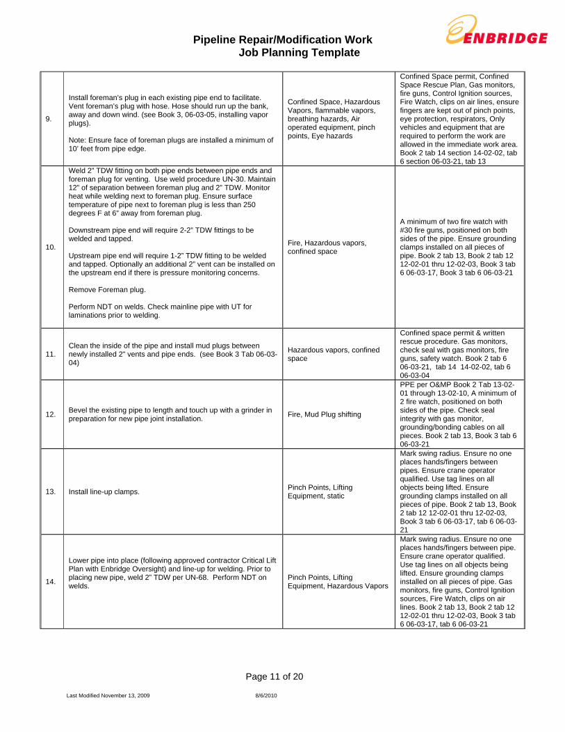
9.
Install foreman’s plug in each existing pipe end to facilitate. Vent foreman’s plug with hose. Hose should run up the bank, away and down wind. (see Book 3, 06-03-05, installing vapor plugs). Note: Ensure face of foreman plugs are installed a minimum of 10’ feet from pipe edge.
Confined Space, Hazardous Vapors, flammable vapors, breathing hazards, Air operated equipment, pinch points, Eye hazards
Confined Space permit, Confined Space Rescue Plan, Gas monitors, fire guns, Control Ignition sources, Fire Watch, clips on air lines, ensure fingers are kept out of pinch points, eye protection, respirators, Only vehicles and equipment that are required to perform the work are allowed in the immediate work area. Book 2 tab 14 section 14-02-02, tab 6 section 06-03-21, tab 13
10.
Weld 2” TDW fitting on both pipe ends between pipe ends and foreman plug for venting. Use weld procedure UN-30. Maintain 12” of separation between foreman plug and 2” TDW. Monitor heat while welding next to foreman plug. Ensure surface temperature of pipe next to foreman plug is less than 250 degrees F at 6” away from foreman plug. Downstream pipe end will require 2-2” TDW fittings to be welded and tapped. Upstream pipe end will require 1-2” TDW fitting to be welded and tapped. Optionally an additional 2” vent can be installed on the upstream end if there is pressure monitoring concerns. Remove Foreman plug. Perform NDT on welds. Check mainline pipe with UT for laminations prior to welding.
Fire, Hazardous vapors, confined space
A minimum of two fire watch with #30 fire guns, positioned on both sides of the pipe. Ensure grounding clamps installed on all pieces of pipe. Book 2 tab 13, Book 2 tab 12 12-02-01 thru 12-02-03, Book 3 tab 6 06-03-17, Book 3 tab 6 06-03-21
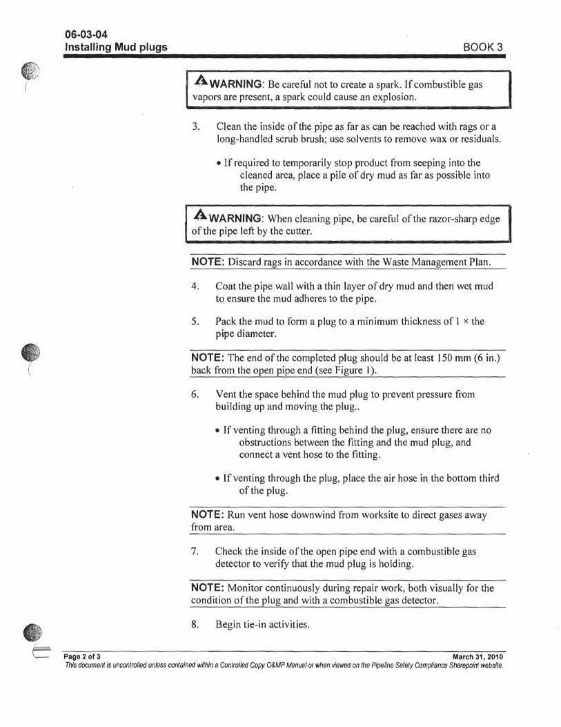
11. Clean the inside of the pipe and install mud plugs between newly installed 2” vents and pipe ends. (see Book 3 Tab 06-03-04)
Hazardous vapors, confined space
Confined space permit & written rescue procedure. Gas monitors, check seal with gas monitors, fire guns, safety watch. Book 2 tab 6 06-03-21, tab 14 14-02-02, tab 6 06-03-04
12. Bevel the existing pipe to length and touch up with a grinder in preparation for new pipe joint installation.
Fire, Mud Plug shifting
PPE per O&MP Book 2 Tab 13-02-01 through 13-02-10, A minimum of 2 fire watch, positioned on both sides of the pipe. Check seal integrity with gas monitor, grounding/bonding cables on all pieces. Book 2 tab 13, Book 3 tab 6 06-03-21
13. Install line-up clamps. Pinch Points, Lifting Equipment, static
Mark swing radius. Ensure no one places hands/fingers between pipes. Ensure crane operator qualified. Use tag lines on all objects being lifted. Ensure grounding clamps installed on all pieces of pipe. Book 2 tab 13, Book 2 tab 12 12-02-01 thru 12-02-03, Book 3 tab 6 06-03-17, tab 6 06-03-21
14.
Lower pipe into place (following approved contractor Critical Lift Plan with Enbridge Oversight) and line-up for welding. Prior to placing new pipe, weld 2” TDW per UN-68. Perform NDT on welds.
Pinch Points, Lifting Equipment, Hazardous Vapors
Mark swing radius. Ensure no one places hands/fingers between pipe. Ensure crane operator qualified. Use tag lines on all objects being lifted. Ensure grounding clamps installed on all pieces of pipe. Gas monitors, fire guns, Control Ignition sources, Fire Watch, clips on air lines. Book 2 tab 13, Book 2 tab 12 12-02-01 thru 12-02-03, Book 3 tab 6 06-03-17, tab 6 06-03-21
Pipeline Repair/Modification Work Job Planning Template
Page 12 of 20
Last Modified November 13, 2009 8/6/2010
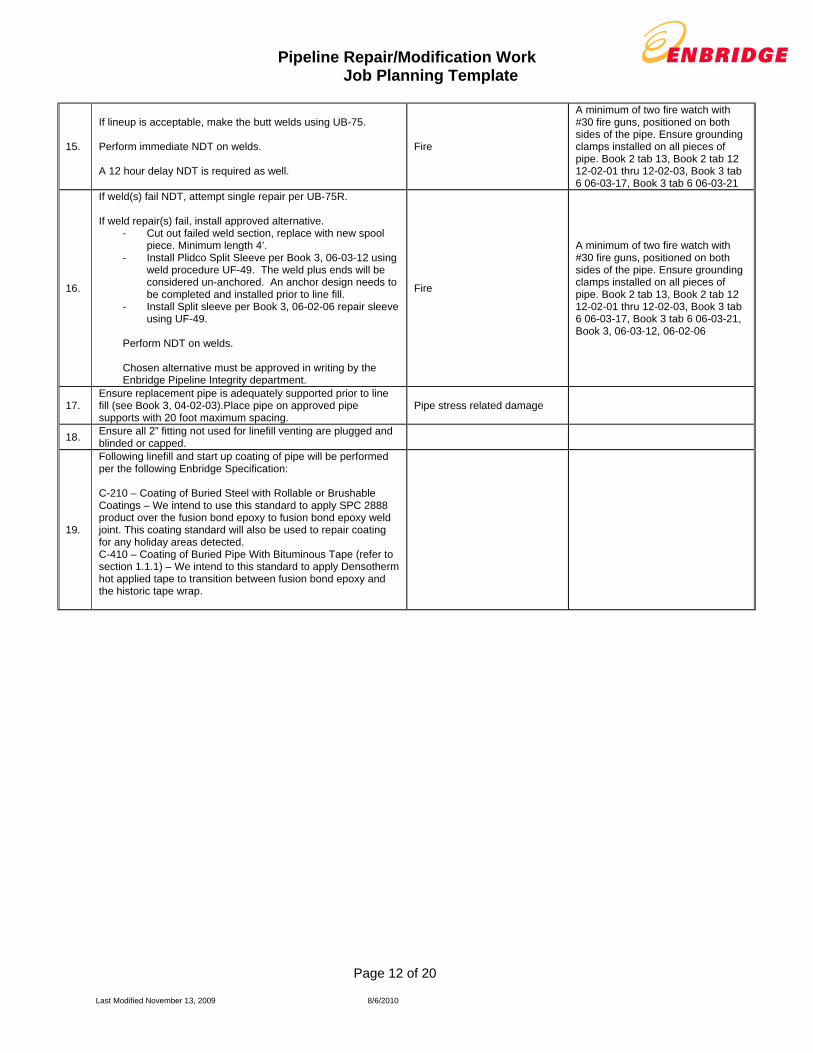
15.
If lineup is acceptable, make the butt welds using UB-75. Perform immediate NDT on welds. A 12 hour delay NDT is required as well.
Fire
A minimum of two fire watch with #30 fire guns, positioned on both sides of the pipe. Ensure grounding clamps installed on all pieces of pipe. Book 2 tab 13, Book 2 tab 12 12-02-01 thru 12-02-03, Book 3 tab 6 06-03-17, Book 3 tab 6 06-03-21
16.
If weld(s) fail NDT, attempt single repair per UB-75R. If weld repair(s) fail, install approved alternative.
- Cut out failed weld section, replace with new spool piece. Minimum length 4’.
- Install Plidco Split Sleeve per Book 3, 06-03-12 using weld procedure UF-49. The weld plus ends will be considered un-anchored. An anchor design needs to be completed and installed prior to line fill.
- Install Split sleeve per Book 3, 06-02-06 repair sleeve using UF-49.
Perform NDT on welds. Chosen alternative must be approved in writing by the Enbridge Pipeline Integrity department.
Fire
A minimum of two fire watch with #30 fire guns, positioned on both sides of the pipe. Ensure grounding clamps installed on all pieces of pipe. Book 2 tab 13, Book 2 tab 12 12-02-01 thru 12-02-03, Book 3 tab 6 06-03-17, Book 3 tab 6 06-03-21, Book 3, 06-03-12, 06-02-06
17. Ensure replacement pipe is adequately supported prior to line fill (see Book 3, 04-02-03).Place pipe on approved pipe supports with 20 foot maximum spacing.
Pipe stress related damage
18. Ensure all 2” fitting not used for linefill venting are plugged and blinded or capped.
19.
Following linefill and start up coating of pipe will be performed per the following Enbridge Specification: C-210 – Coating of Buried Steel with Rollable or Brushable Coatings – We intend to use this standard to apply SPC 2888 product over the fusion bond epoxy to fusion bond epoxy weld joint. This coating standard will also be used to repair coating for any holiday areas detected. C-410 – Coating of Buried Pipe With Bituminous Tape (refer to section 1.1.1) – We intend to this standard to apply Densotherm hot applied tape to transition between fusion bond epoxy and the historic tape wrap.

Pipeline Repair/Modification Work Job Planning Template
Page 13 of 20
Last Modified November 13, 2009 8/6/2010
Line-fill & Start-up Procedures Potential Hazards Hazard
Controls
(SUBJECT TO PHMSA APPROVAL)
Pipeline Repair/Modification Work Job Planning Template
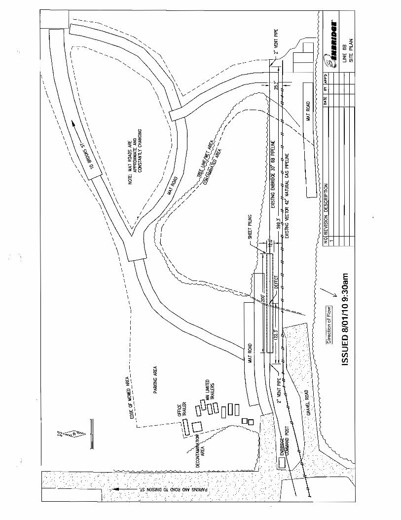
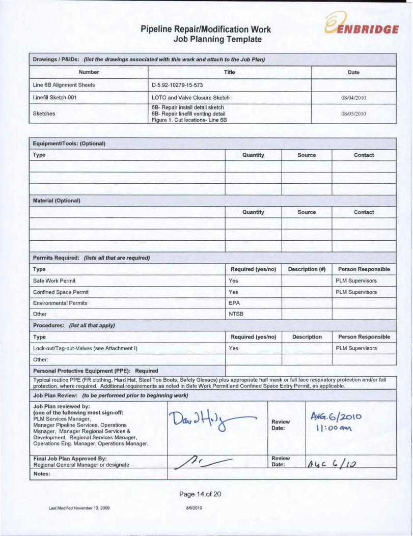
Drawings I P&IDs: (list the drawings associated with this work and attach to the Job Plan)
Number Title
Une 68 Alignment Sheets 0-5.92-10279-15-573
Unefill Sketch-OOI LOTO and Valve Closure Sketch
66- Repair install detail sketch Sketches 68- Repair linefill venting detail
Figure 1. Cut locations- Line 68
EquipmentITools: (Optional)
Type Quantity
Material (Optional)
Quantity
Permits Requined: (lists al/ that are required)
ENBRIDGE
Date
01W412010
08<\:)512010
Source Contact
Source Contact
Type Required (yes/no) Description (#) Person Responsible
Safe Work Permit Yes PLM Supervisors
Confined Space Permit Yes PLM Supervisors
Environmental Permits EPA
Other NTS6
Procedures: (I/st al/ that apply)
Type Required (yes/no) Description Person Responsible
Lock-outlTag-out-Valves (see Attachment I) Yes PLM Supervisors
Other:
Personal Protective Equipment (PPE): Required
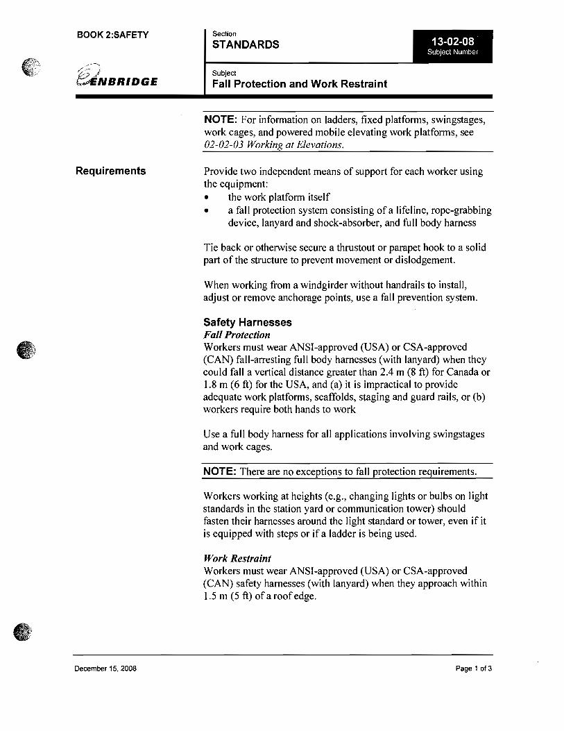
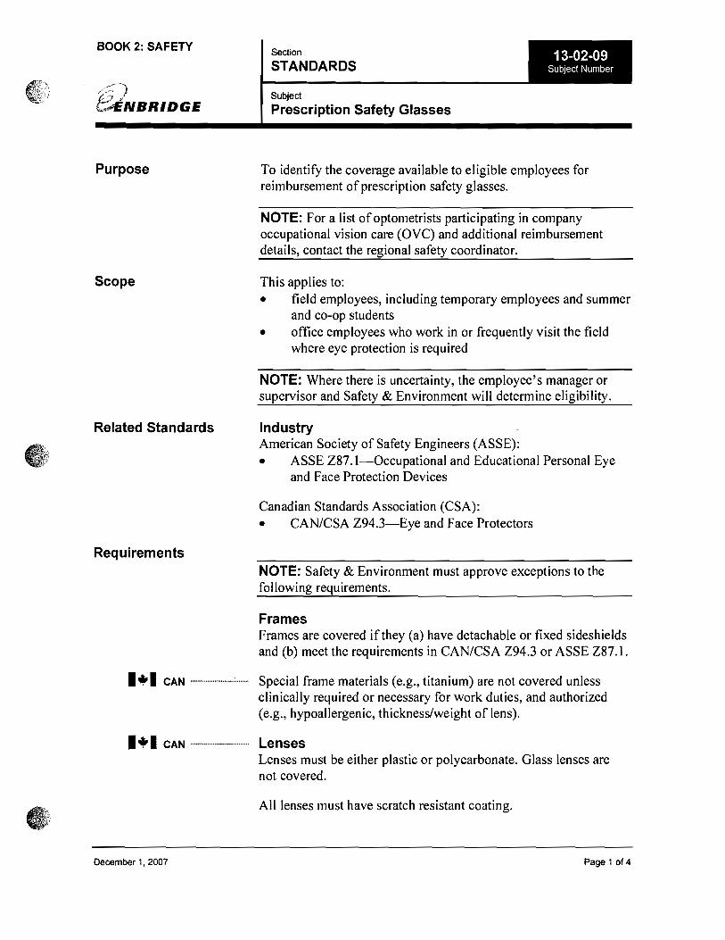
Typical routine PPE (FR clothing, Hard Hat, Steel Toe Boots, Safety Glasses) plus appropriate half mask or full face respiratory protection and/or fall protection, where required. Additional requirements 8S noted in Safe Work Permit and Confined Space Entry Permit, as applicable.
Job Plan Review: (to be performed prior to beginning work)
Job Plan reviewed by:
Th,J\-\')~ {one of the following must sign-off:
A~.b/~\O PLM Services Manager, Review Manager Pipeline Services, Operations Date: II'- 00 "''''' Manager, Manager Regional Services & Development, Regional Services Manager, Operations Eng. Manager, Operations Manager,
Final Job Plan Approved By: /~
Review Ibl4c 'Ii.? Regional General Manager or designate Date:
Noles:
Page 14 of 20
Last Modified November 13, 2009 OI!lI2O,O

Pipeline Repair/Modification Work Job Planning Template
Page 15 of 20
Last Modified November 13, 2009 8/6/2010
Date:
Assigned to/Date:
Post Job Notes:
1.
2.
3.

Pipeline Repair/Modification Work Job Planning Template
Page 17 of 20
Last Modified November 13, 2009 8/6/2010
Seq #
Isolation Procedure Steps Make a list of all valves that will be operated and in what order they will be turned (include vent and drainage valves). Attach piping schematics if available. Confirmation of valve position as described in this list shall be the final step before operating the last valve.
Lo
ck #
Initial V
alve S
tatus O
/ C
Sh
utd
ow
n V
alve Statu
s O / C
Tim
e
Initials
Lo
cked at M
CC
Lo
cked at E
qu
ip
Re-P
ressurize
Statu
s O / C
Tim
e
Initials
Example Trap isolation valve (R2.1) to be closed
C
Upstream
599.43-6-V
607.63-6-V (M) C
6-SDV-1 C
6-SSV-1 C
607.66-6-V C
Down Stream
610.61-6-V
C
611.00-6-V (M) C
620.66-6-V C
Rectifiers
Appropriate PPE & Equipment? YES
Isolation Procedure Steps Reviewed & Approved? YES
FINAL CHECK BEFORE DE-PRESSURIZING Are all sealing devices (valves) in proper position? YES
Assigned Person in Charge of work
Signed:
FINAL CHECK BEFORE RE-PRESSURIZING

Pipeline Repair/Modification Work Job Planning Template
Page 18 of 20
Last Modified November 13, 2009 8/6/2010
Are all sealing devices (valves) in proper position?
YES
Assigned Person in Charge of work Signed:
Plan Isolate Depressurize Test for LEL’s Vapors etc
Start Work
Re-pressurize
Confirm Sealing Device Positions
Check for Tools & Personnel
Work Complete
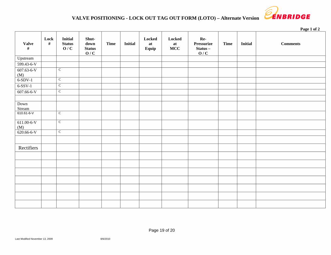
VALVE POSITIONING - LOCK OUT TAG OUT FORM (LOTO) – Alternate Version
Page 19 of 20
Last Modified November 13, 2009 8/6/2010
Page 1 of 2
Valve #
Lock
#
Initial Status O / C
Shut- down Status O / C
Time
Initial
Locked
at Equip
Locked
at MCC
Re-
Pressurize Status –
O / C
Time
Initial
Comments
Upstream 599.43-6-V 607.63-6-V (M)
C
6-SDV-1 C 6-SSV-1 C 607.66-6-V C Down Stream
610.61-6-V
C
611.00-6-V (M)
C
620.66-6-V C
Rectifiers

VALVE POSITIONING - LOCK OUT TAG OUT FORM (LOTO) – Alternate Version
Page 20 of 20
Last Modified November 13, 2009 8/6/2010
Page 2 of 2
FINAL CHECK BEFORE DE-PRESSURIZING
Are all sealing devices (valves) in proper position? YES
Person in Charge of work Signed:
FINAL CHECK BEFORE RE-PRESSURIZING Are all sealing devices (valves) in proper position?
YES
Person in Charge of work Signed:
Plan Isolate Depressurize Test for LEL’s Vapors etc
Start Work
Re-pressure
Confirm Sealing Device Positions
Check for Tools & Personnel
Work Complete


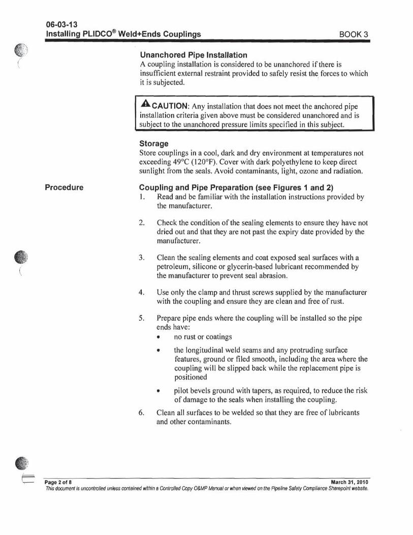
GWD 217710 GWD 217720 GWD 217730 GWD 217740
39.659 ft 40.243 ft 40.102 ft
4 ft
19 ft
26 ft
4 ft
Approx Center Of Rupture
CUT
CUT 3
CUT
Figure 1. Cut Locations Line 6B
Flow Direction
DRAINCUT

TM
607 608 609 610 611
608
xxx
xxx