© 2013 ibm corporation networking fundamentals andy wright global field marketing, ibm system...
TRANSCRIPT

© 2013 IBM Corporation
Networking FundamentalsAndy WrightGlobal Field Marketing, IBM System Networking
IBM TGVL: System Networking FoundationsJune 2013
© 2013 IBM Corporation
System Networking Top Gun
Instructor Bio: Andy Wright
Experience:
Over thirty years of experience in Information Technology Services Sales and Marketing.
•2013-Present Channel and Sales Enablement – IBM System Networking
•2004-2013 Product Marketing Director – Global Knowledge
•2002-2004 Sales Manager – Channel Advisor
•2000-2002 Marketing Director – Static Control Components
•1981-2000 IBM (Netfinity/System x Marketing, ThinkPad Product Marketing,
and Sales positions in CA and MN, IT Programming)
Education:
•Bachelor of Science, Business Admin Management & Computer Science, University of
Wisconsin - Platteville
Hobbies:
• Beach, Civic Organizations, Travel

© 2013 IBM Corporation
System Networking Top Gun
Agenda
Basics – what is a network, components, terminology
OSI model & layers
Virtualization & networking
Storage & network convergence

© 2013 IBM Corporation
System Networking Top Gun
What Is A Network?
Physical and logical interconnection of “internet aware” devices
Networks provide an infrastructure to share resources and information
A network is a resource, or group of resources, that share common communication infrastructure to distribute data
Networks can scale greatly in size, ranging from two to three machines, to millions of interconnected networks
Clients, servers, network interface
© 2013 IBM Corporation
System Networking Top Gun
Network Interface and Speeds
Devices have network interfaces – port or nic (network interface card) Ethernet is the standard Speeds at which computers and servers can access data over the network is
determined by the speed of the ‘wire’ they connect to These ‘wire’ or ‘media’ speeds are rapidly increasing to mind bogglingly fast data
rates
– 1 Gb speeds over Ethernet has been the standard
– 10 Gb becoming more persuasive
– 40 Gb products exist
– 100 Gb is coming Ethernet has become more reliable with advent of Lossless
– Lossless Ethernet: enhancement to Ethernet for data center environments• Data Center Bridging (DCB) indicates lossless Ethernet – used by IEEE standards
group. • Convergence Enhanced Ethernet (CEE) – IBM’s trade marked term• Data Center Ethernet (DCE) – Cisco’s trade marked term

© 2013 IBM Corporation
System Networking Top Gun
Parts of a Network
Node - a device (servers, storage, computers, etc) connected to the network Switch – connects devices to allow devices to communicate to each other Router – helps pass data to the correct device
Switch RouterNode

© 2013 IBM Corporation
System Networking Top Gun
Access Devices (or Endpoint Devices)
Devices that actually utilize network resources In the data center, these are typically servers, or storage devices In the office, this includes anything with an Ethernet port, including PCs,
IP phones, POS systems, and virtually anything else that might need to talk to a network
Access devices need to connect, or “uplink” with the rest of the network. This is done by connecting to a switch

© 2013 IBM Corporation
System Networking Top Gun
Routers
Act like traffic GPS units Responsible for understanding where traffic needs
to be moved across the network Also responsible for knowing whether it is
appropriate to be sending certain devices’ traffic to other devices across the network
Utilize technologies to allow multiple users to share a single internet connection
Analogy: Real-time translator. It will know that if the finance department speaks English, in order to talk to the human resources department, it will need to translate to French in real time. The router will also know that the employees in marketing probably shouldn’t need to talk to the payroll department

© 2013 IBM Corporation
System Networking Top Gun
Ethernet Switches
Act as the “skeleton” of the network – provide the framework both physically and logically to connect endpoint devices to the network. No switches, no network!
Unlike other network devices, switches typically have a high port density, meaning, a larger port count (often 24 to 48+ ports!)
Have transitioned from “connectivity” boxes to complex devices capable of performing all of the aforementioned roles, and sometimes, more
A lot of players in this market, including IBM’s System Networking portfolio, in addition to products from Cisco, HP, Juniper and many, many others

© 2013 IBM Corporation
System Networking Top Gun
Local and Wide Area Networks
Computer networks allow applications operating on various computers to communicate with one another.
New YorkLAN
LondonLAN
WAN
Networking Standards
Ex IEEE
Server 1
Server 2
Vendor Interoperability• Competition - connect diff vendors
• Ease of Networking

© 2013 IBM Corporation
System Networking Top Gun
Networking OSI Reference Model
11
Layer 7 Application
Layer 6 Presentation
Layer 5 SessionLayer 4 TransportLayer 3 NetworkLayer 2 Data LinkLayer 1 Physical • Transmission method of bits
•Transmission across physical link (LAN/WAN)
•Addressing and packet transmission (best path)
•Data tracking (End-to-end connection)
•Job Management tracking Inter-host communication
•Data representation (Encoding Language)
•Network processes to applications
Destination Source VLAN Type / Length Data CRC
Layers 2 – 3 (Know from & where to) Layers 4+ (what’s inside)

© 2013 IBM Corporation
System Networking Top Gun
Network Layers Continued
The key differentiation between most switches is their degree of intelligence
Switches typically fall under the category of: Layer 2, Layer 2/3, and Layer 4+ So, what does this mean? Let’s quickly discuss the concept of a frame
Destination Source VLAN Type / Length Data CRC
Layers 2 - 3 Layers 4+

© 2013 IBM Corporation
System Networking Top Gun
Network Layers – The Analogy
Frames are little packages wrapped up inside each other When network devices can understand what’s wrapped up deep inside a
frame, they’re able to make intelligent decisions about how to interact with frames
Layer 2/3 switches understand where the frames come from, and where they have to go
Layer 4+ switches understand what’s inside a frame, and can actually interact with frames to perform intelligent actions like reply to a system’s request for information before it is actually processed by the destination system
Allows for intelligent load balancing and other complex operations based on content rather than source or destination

© 2013 IBM Corporation
System Networking Top Gun
Layer 1: Physical Layer
14
Defines the physical characteristics of the network such as connections Physical media type does not dictate the type of internet traffic that can flow across it.
Copper RJ45, DAC SFP+ or Fibre, all can carry “Ethernet” traffic Whether travelling by train, bus, or car, as long as the objective is to get from point A to
point B, the method travelled is irrelevant
Ethernet standards - IEEE 802.3
Support different distances – Short Range 100’s meters, Long Range 10 KM
Pass-through would be an example (EN4091)
Copper RJ45(CAT5, CAT6, CAT6e)
SFP+ DAC(Passive / Active)
Fibre Optics(Ex. LC/LC)

© 2013 IBM Corporation
System Networking Top Gun
Layer 2: Data Link Layer
15
Provides reliable transit of data across a physical link Defines physical addressing, network topology, and is also concerned
with error notification, sequencing of frames and flow control. Consists of:
– MAC layer - Provides unique address for an NIC– LCC (Logical Link Control) layer
Examples of Layer 2 switches– All the Ethernet devices in IBM portfolio support Layer 2 (except
Pass-thru)– Layer 2 offerings:
• All RackSwitch offerings• Embedded - EN4093/R, CN4093
• Basic L2 only: Easy Connect Mode & SI4093

© 2013 IBM Corporation
System Networking Top Gun
Layer 3: Network Layer Provides connectivity and network path selection between two networks. Required when going across domains or VLAN’s "What's the difference between a Layer 3 switch and a router?"
– Layer 3 switches have optimized hardware passing data traffic as fast as Layer 2 switches our usually faster because it is built on switching HW.
– Layer 3 switches make decisions regarding how to transmit traffic like a router does.
Examples:
– All IBM RackSwitch and embedded switches
– Reduce need for external switches & ports
– Can help reduce costs• Acquisition costs
• Operating costs – power, cooling & IT resources
– Can improve availability & security

© 2013 IBM Corporation
System Networking Top Gun
Campus
Access Layer
Aggregation Layer
Core Layer
Early Ethernet Campus Evolution
In the beginning, Ethernet was used to interconnect stations (e.g. dumb terminals), initially through repeater & hub topologies,
Then eventually through switched topologies. Ethernet campuses evolved into a structured
network typically divided into a Core, Service (e.g. firewall), Aggregation and Access Layer.
– Typically: core, services, aggregation & access planes.
– Traffic is mostly North-South(directed outside campus).
– To avoid spanning tree problems, campus networks typically are divided at access.
The industry liked the tree structure & applied to DC
WANWAN
5%5%
95%
95%
Lay
er3
© 2013 IBM Corporation
System Networking Top Gun
Laye
r2SAN
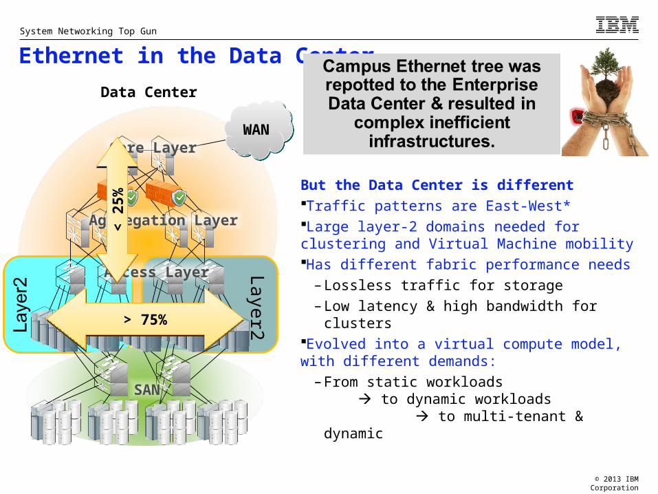
Ethernet in the Data Center
But the Data Center is differentTraffic patterns are East-West* Large layer-2 domains needed for clustering and Virtual Machine mobilityHas different fabric performance needs
– Lossless traffic for storage
– Low latency & high bandwidth for clustersEvolved into a virtual compute model, with different demands:
– From static workloads to dynamic workloads
to multi-tenant & dynamic
Data Center
Access Layer
Core Layer
Aggregation Layer
> 75%> 75%
< 2
5%<
25%
WANWAN

© 2013 IBM Corporation
System Networking Top Gun
Virtualization and Networking Gartner states that virtualization and consolidation are the two largest movements
occurring in the data centre While the greatest degree of focus has been on the virtualization of “traditional”
computing systems like servers, virtual network technology is becoming a huge market
Virtualization vendors like VMware and Xen have products to meet this need, however 3rd party networking vendors like IBM have also developed incredibly elegant and sophisticated technology to enable administrators to virtualize network equipment
Virtualization technologies like IBM’s Virtual Fabric, VMready and SDN VE are changing the way IT personnel are thinking about network technologies
The technologies currently available to facilitate network virtualization are discussed in greater detail in the Networking Trends education module
© 2013 IBM Corporation
System Networking Top Gun
Virtualization: Virtualizing Network Components
While a more technically involved concept, it is important to understand that while virtual hardware is logical, it is ultimately dependent on physical hardware in order to actually work in a way that is useful across a network
With industry buzzwords like “virtual switches, virtual NICs and virtual fabrics” being discussed, understanding that networking vendors like IBM have a wealth of technologies available to meet each of these unique requirements that work well with other vendors – this is a huge advantage.

© 2013 IBM Corporation
System Networking Top Gun
Standards will impact future Data Center
Virtualization IEEE 802.1Qbg
– Server-network edge virtualization – Uniform view of VMs in the
hypervisors and the network– Visibility of VM traffic in the network– Automatic migration of port profiles
IEEE 802.1Qbh/r– TAG added in Hardware to the
Ethernet frame.
OpenFlowSilos – app specific
WEBAP
DB
WEBAP
DB
WEBAP
DB
WEBAP
DB
IP NWIP NW▌ Inefficient
▌ Complex
▌ Slow response
▌ Static
▌ Vendor lock
Optimization software control
WEBAP
DBWEBAPDB
WEBAPDB
WEBAPDB
IP NWIP NW▌ Optimized
▌ Simple
▌ Agile
▌ Dynamic
▌ Low cost

© 2013 IBM Corporation
System Networking Top Gun
SAN – The Storage Area Network
Servers need storage! In larger scale networks, this typically means servers are attached to storage systems over the SAN on separate physical infrastructure
This technology is typically driven over optical FibreChannel connections, however FibreChannel does run on copper cable as well
The storage networks have traditionally been kept separate from data networks because storage technology is delivered to servers at a “block by block” level. Basically, the electronic representation of physical sectors on a hard drive is transmitted back and forth between servers and storage. This means that storage networks must be very high speed, and incredibly reliable. Data networks are “lossy” networks, which is unacceptable for storage
FC Switch
WWN
FCoE to FC Gateway
10G Loss Less Ethernet2/4/8G Fiber Channel
F-port N-portWWN WWN MAC
MAC
NPIV F-port
CNA
© 2013 IBM Corporation
System Networking Top Gun
SAN – How We Talk to Storage
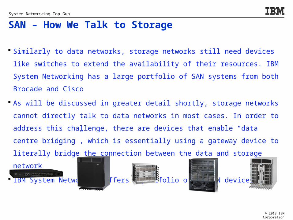
Similarly to data networks, storage networks still need devices like switches to
extend the availability of their resources. IBM System Networking has a large
portfolio of SAN systems from both Brocade and Cisco
As will be discussed in greater detail shortly, storage networks cannot directly talk
to data networks in most cases. In order to address this challenge, there are
devices that enable “data centre bridging”, which is essentially using a gateway
device to literally bridge the connection between the data and storage network
IBM System Networking offers a portfolio of 16 SAN devices

© 2013 IBM Corporation
System Networking Top Gun
Network Convergence: Overview
Historically, different network services required different communications infrastructure
Telephones ran on telephone networks, storage was accessed over storage networks and data was contained within data networks
This is no longer the case! As the performance of networks increases, and vendors are able to produce
technology capable of meeting the needs of multiple technologies sharing a common ‘wire’, there is, and will continue to be a major shift away from physically decoupled networks to physically shared but logically segregated networks
Network convergence is rapidly becoming the biggest trend in the networking world

© 2013 IBM Corporation
System Networking Top Gun
Gateway
iSCSI Storage
Array
FCoE Storage Array
NFS/CIFS NAS FC Arrays
Fibre Channel
Lossless
Ethernet
Gateway
This educational material is intended for your use in selling. It is NOT a deliverable for your clients.25
Network Convergence: What Is It?

© 2013 IBM Corporation
System Networking Top Gun
Network Convergence: FibreChannel & Storage Area Networks Typically in enterprise environments, storage has been attached to the network via an
independent, physically decoupled infrastructure known as the SAN, or storage area network The de-facto method of attaching servers to storage has been to leverage the FibreChannel
protocol, which uses optical connections and a specific ‘protocol’ or ‘language’ to facilitate communication between servers and storage systems
IBM markets a number of SAN-specific products including FibreChannel switches, as FC is still the dominant product in this market
FC systems have also traditionally operated at faster speeds than Ethernet technology
FibreChannel does have several drawbacks however, mainly the cost associated with maintaining and procuring independent infrastructure just for storage
As will be discussed in the following slides, convergence is rapidly negating the need for physically independent networks

© 2013 IBM Corporation
System Networking Top Gun
Network Convergence: The Challenges of Current Technologies
There are two major roadblocks impeding the rate at which convergence is being adopted
– Many networks still operate with gigabit Ethernet technology. Unfortunately this speed is insufficient to properly trunk high bandwidth storage applications
– The second major challenge is that Ethernet technology was not lossless meaning that the technology is designed with the assumption that frames will be dropped by networking devices if certain conditions like excess capacity or network problems occur
Storage data is incredibly sensitive to data loss and latency and thus Ethernet as currently implemented is not best suited for many mission-critical storage applications
There is technology currently being standardized to address these challenges

© 2013 IBM Corporation
System Networking Top Gun
Network Convergence: Leveraging New Technologies
10 gigabit per second infrastructure is now becoming the standard in data centres which greatly increases the suitability for Ethernet in storage applications
40 gigabit per second technology is already available (with limited implementation, however) and standards bodies are working 100+ gigabit per second technology
Lossless communications technologies such as CEE, or Converged Enhanced Ethernet eliminate the issues associated with network packet loss by implementing QoS
FCoE, or FibreChannel over Ethernet allows FibreChannel “frames” to be encapsulated, or “packaged” inside of Ethernet frames permitting traditional network equipment to understand how to talk to storage equipment
iSCSI and NAS will allow administrators to utilize the same technological concepts to increase availability and access to their network attached storage
Other technologies that will be able to leverage lossless communications including high performance computing clusters and computational systems

© 2013 IBM Corporation
System Networking Top Gun
IBM System Networking - Overview
Mission: Help IBM deliver on the promise of the best “System’s Company” by providing the best server-to-server, server-to-storage, storage-to-storage, and system-to-system interconnect
Integral part of many IBM System and Solution offerings – Optimization, automation and integration
Deliver lower latency, loss less, low cost and low power technology
Built on industry standards & designed for future
Seamless integration with Cisco, Juniper and others
Critical in fighting off the competition, increase revenue & profit
Storage Software
Servers
Networking
© 2013 IBM Corporation
System Networking Top Gun
ありがとうございました
MerciGrazie
Gracias
Obrigado
Danke
Japanese
Hebrew
Thank YouEnglish
French
Russian
German
Italian
Spanish
Brazilian Portuguese
Hindi
Tamil
Korean
Thai
Simplified Chinese
ArabicJapaneseJapanese
Dziękuję
Korean
Polish
Terima Kasih Malay
© 2013 IBM Corporation
Learning Points
This educational material is intended for your use in selling. It is NOT a deliverable for your clients.
© 2013 IBM Corporation
System Networking Top Gun
This educational material is intended for your use in selling. It is NOT a deliverable for your clients.32
Networking is critical to clients business A network is the physical and logical connect of devices A network is a resource that shares a common communication infrastructure
to distribute data Ethernet networks speed and reliability has increased tremendously over
the years Servers and storage are nodes also know as access or endpoint devices
that utilize network resources Ethernet switches provide the framework both physically and logically to
connect endpoint devices to the network. Switches typically have high port density.
32
Learning Points – Part 1

© 2013 IBM Corporation
System Networking Top Gun
This educational material is intended for your use in selling. It is NOT a deliverable for your clients.33
OSI Reference Model is made up of seven layers: – Layer 7 Application: Network processes to applications– Layer 6 Presentation: Data representation (Encoding)– Layer 5 Session: Job Management track– Layer 4 Transport: Data Tracking– Layer 3 Network: Addressing and packet transmission (best path)– Layer 2 Data Link: Transmission across physical link– Layer 1 Physical: Transmission method
Switches typically fall under the category of Layer 2, Layer 2/3 and Layer 4+ Frames are packages containing information about the destination, the source,
VLAN, Type/Length, Data and CRC (for validation and error checking) Layer 2/3 switches understand where the frames come from and where they are
supposed to go to Layer 4+ switches understand what’s inside a frame and can interact with the
frame to perform actions like reply to a system’s request for information before it’s actually processed by the destination system
33
Learning Points – Part 2

© 2013 IBM Corporation
System Networking Top Gun
This educational material is intended for your use in selling. It is NOT a deliverable for your clients.34
Layer 1 – the physical layer–Defines the physical characteristics like the connection – Can be copper, fibre optical, or SFP+ DAC. All can carry Ethernet traffic–The physical cable varies in distances it can carry signals
Layer 2 – the data link layer– provides for the reliable transit of data across a physical link–Defines the physical addressing, network topology and error notification–Consists of MAC layer – provides unique address for a network interface card (nic) and Logical Link Control layer
Layer 3 - Network Layer–Provides the connectivity and network path selection between two networks–Required when going across domains or VLANs.
34
Learning Points – Part 3
© 2013 IBM Corporation
System Networking Top Gun
This educational material is intended for your use in selling. It is NOT a deliverable for your clients.35
Early Ethernet Campus – used to connect dumb terminals through hubs and repeaters. Eventually switches were used and almost all traffic flowed North – South through a core switch. Ethernet in Data Center – traffic patterns are East – West server to server, virtual machine to virtual machine. Virtualization has made significant changes to servers and storage. Now network virtualization is gaining popularity. Storage has typically used FibreChannel connections With the advent of more reliable (lossless) and higher performance, Ethernet is gaining acceptance as a viable alternative to FC. Network convergence is becoming one of the biggest trends in the networking world.
35
Learning Points – Part 4

© 2013 IBM Corporation
System Networking Top Gun
This educational material is intended for your use in selling. It is NOT a deliverable for your clients.
Disclaimers and Trademarks

© 2013 IBM Corporation
System Networking Top Gun
This educational material is intended for your use in selling. It is NOT a deliverable for your clients.
8 IBM Corporation 1994-2013. All rights reserved.References in this document to IBM products or services do not imply that IBM intends to make them available in every country.
Trademarks of International Business Machines Corporation in the United States, other countries, or both can be found on the World Wide Web at http://www.ibm.com/legal/copytrade.shtml.
Intel, Intel logo, Intel Inside, Intel Inside logo, Intel Centrino, Intel Centrino logo, Celeron, Intel Xeon, Intel Itanium, and Pentium are trademarks or registered trademarks of Intel Corporation or its subsidiaries in the United States and other countries.Linux is a registered trademark of Linus Torvalds in the United States, other countries, or both.Microsoft, Windows, Windows NT, and the Windows logo are trademarks of Microsoft Corporation in the United States, other countries, or both.UNIX is a registered trademark of The Open Group in the United States and other countries.Java and all Java-based trademarks are trademarks of Sun Microsystems, Inc. in the United States, other countries, or both.Other company, product, or service names may be trademarks or service marks of others.
Information is provided "AS IS" without warranty of any kind.
The customer examples described are presented as illustrations of how those customers have used IBM products and the results they may have achieved. Actual environmental costs and performance characteristics may vary by customer.
Information concerning non-IBM products was obtained from a supplier of these products, published announcement material, or other publicly available sources and does not constitute an endorsement of such products by IBM. Sources for non-IBM list prices and performance numbers are taken from publicly available information, including vendor announcements and vendor worldwide homepages. IBM has not tested these products and cannot confirm the accuracy of performance, capability, or any other claims related to non-IBM products. Questions on the capability of non-IBM products should be addressed to the supplier of those products.
All statements regarding IBM future direction and intent are subject to change or withdrawal without notice, and represent goals and objectives only.
Some information addresses anticipated future capabilities. Such information is not intended as a definitive statement of a commitment to specific levels of performance, function or delivery schedules with respect to any future products. Such commitments are only made in IBM product announcements. The information is presented here to communicate IBM's current investment and development activities as a good faith effort to help with our customers' future planning.
Performance is based on measurements and projections using standard IBM benchmarks in a controlled environment. The actual throughput or performance that any user will experience will vary depending upon considerations such as the amount of multiprogramming in the user's job stream, the I/O configuration, the storage configuration, and the workload processed. Therefore, no assurance can be given that an individual user will achieve throughput or performance improvements equivalent to the ratios stated here.
Photographs shown may be engineering prototypes. Changes may be incorporated in production models.
Trademarks and Disclaimers