© 2011 autodesk advanced techniques for nonlinear contact and drop shock analysis shoubing zhuang...
DESCRIPTION
© 2011 Autodesk Learning Objectives At the end of this class, you will be able to: Recognize fundamental nonlinear contact terminology Define contact pairs in MES Identify and diagnose convergence challenges Create more efficient nonlinear contact models Perform a drop test analysisTRANSCRIPT
© 2011 Autodesk
Advanced Techniques for Nonlinear Contact and Drop Shock AnalysisShoubing ZhuangSr. Research Engineer – Autodesk, Inc.
Mike SmellTechnical Consultant – Autodesk, Inc.
© 2011 Autodesk
Class Summary
This class will explore some of the challenges associated with nonlinear contact models. During this class, we will present a list of tips and tricks to help you breeze through your contact models, even if you are a beginner in nonlinear contact. These tips are summarized from vast experience solving customer issues. A variety of contact models will be used to demonstrate the key learning objectives.

© 2011 Autodesk
Learning Objectives
At the end of this class, you will be able to:
Recognize fundamental nonlinear contact terminology
Define contact pairs in MES
Identify and diagnose convergence challenges
Create more efficient nonlinear contact models
Perform a drop test analysis

© 2011 Autodesk
Introduction to Nonlinear Contact

© 2011 Autodesk
Determine the contact areas
Study deformation of contact parts
Analyze the contact interaction
Obtain contact forces
General Goals of Contact Analysis
© 2011 Autodesk
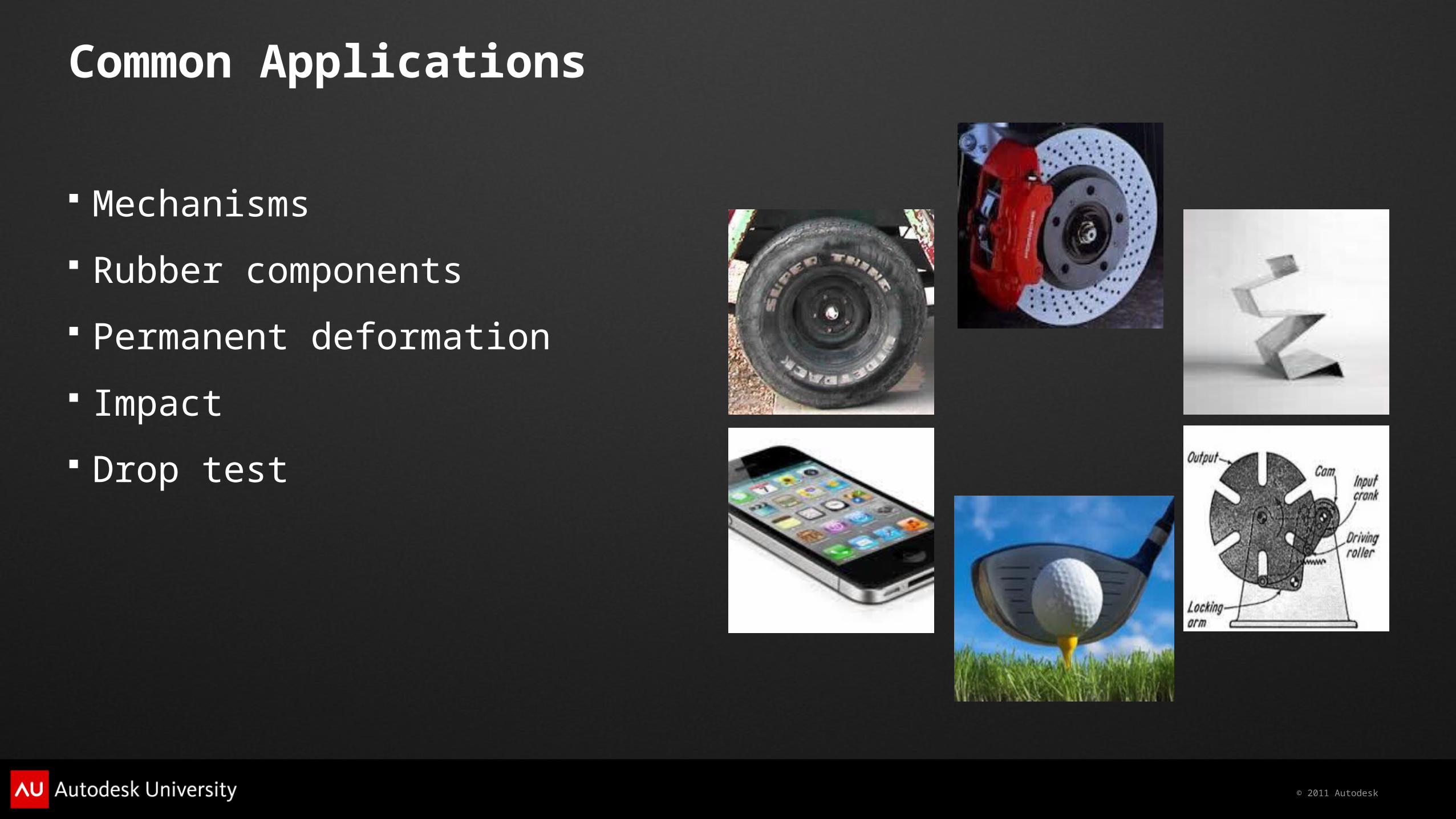
Mechanisms
Rubber components
Permanent deformation
Impact
Drop test
Common Applications

© 2011 Autodesk
Linear vs. Nonlinear Contact Analysis
Linear contact analysis Nonlinear contact analysis
Small displacement Large/Small displacement
Material linearity Material non-linearity/linearity
Small relative motion Large/small relative motion
Static stability Static stability / non-stability

© 2011 Autodesk
Supported Analysis Types
MES with Nonlinear Material Models
Static Stress with Nonlinear Material Models
MES Riks Analysis

© 2011 Autodesk
Frictionless contact (default)
Frictional contact
Slide/No Bounce contact
Tied contact
Contact Methods
© 2011 Autodesk
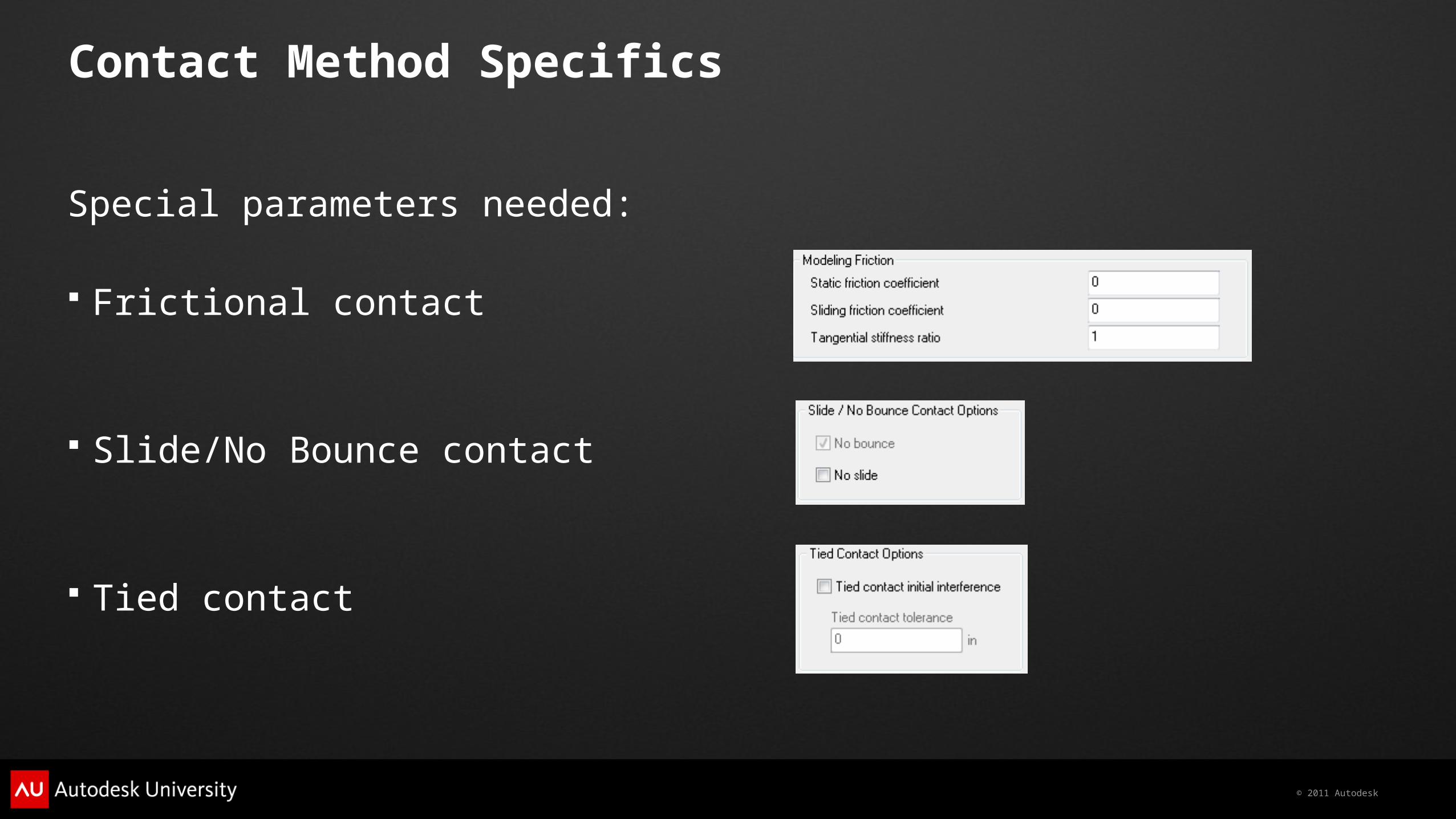
Contact Method Specifics
Special parameters needed:
Frictional contact
Slide/No Bounce contact
Tied contact

© 2011 Autodesk
Frictional Contact
Friction law
Coulomb friction law
Modified Coulomb friction law

© 2011 Autodesk
Automatic (default)
Surface to Surface
Point to Surface
Point to Point
Contact Types
© 2011 Autodesk
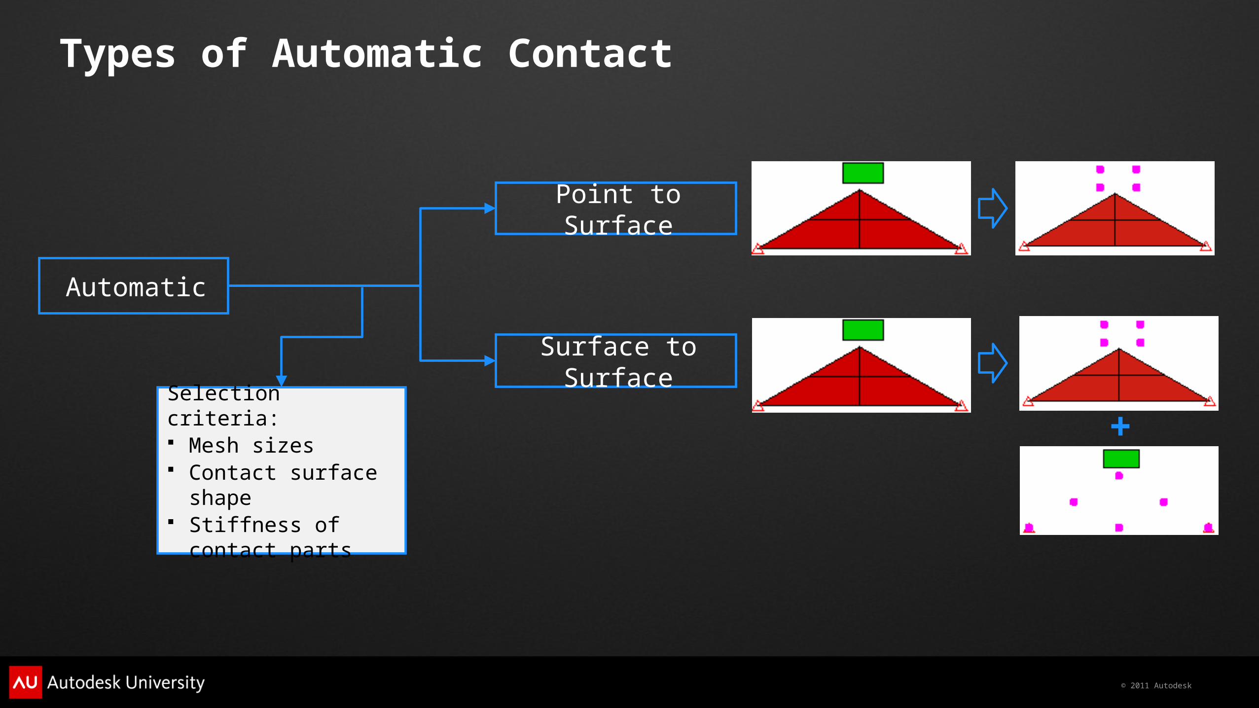
Types of Automatic Contact
Automatic
Point to Surface
Surface to Surface
Selection criteria: Mesh sizes Contact surface shape Stiffness of contact
parts
+
© 2011 Autodesk
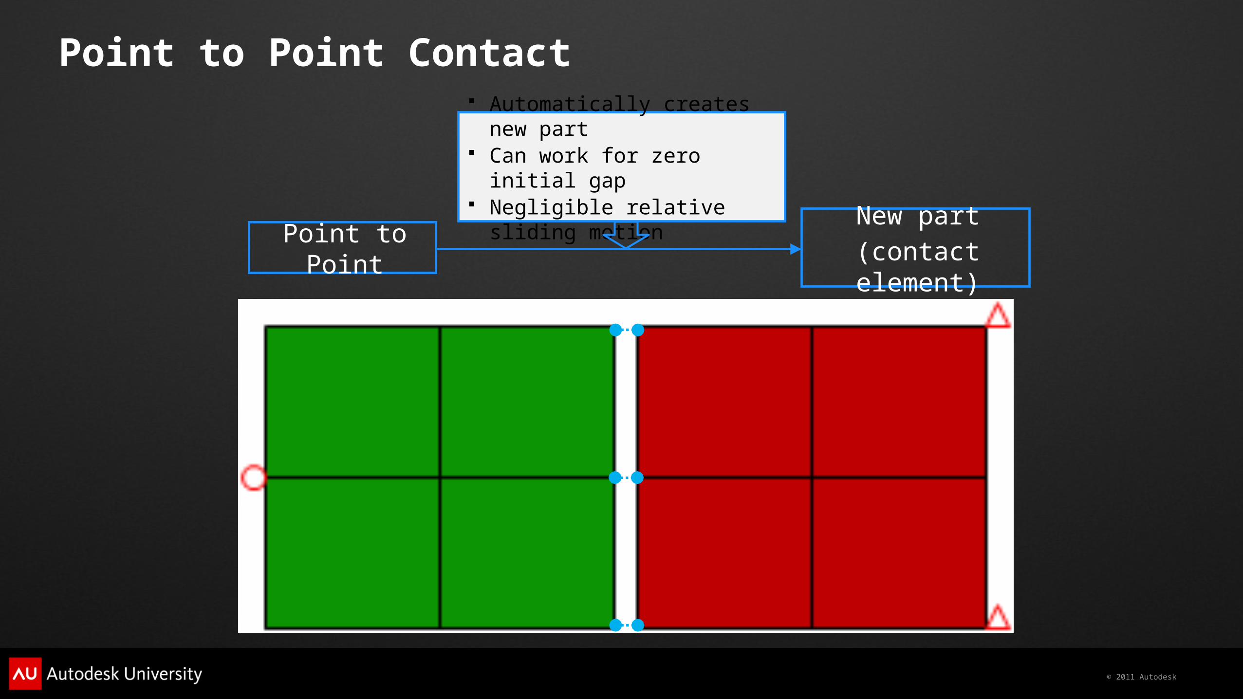
Point to Point Contact
Point to PointNew part
(contact element)
Automatically creates new part Can work for zero initial gap Negligible relative sliding
motion

© 2011 Autodesk
Examples

© 2011 Autodesk
Defining Contact

© 2011 Autodesk
Methods to Define Contact Pairs
FEA editor
General contact dialog

© 2011 Autodesk
Identifying and Diagnosing Convergence Challenges
© 2011 Autodesk
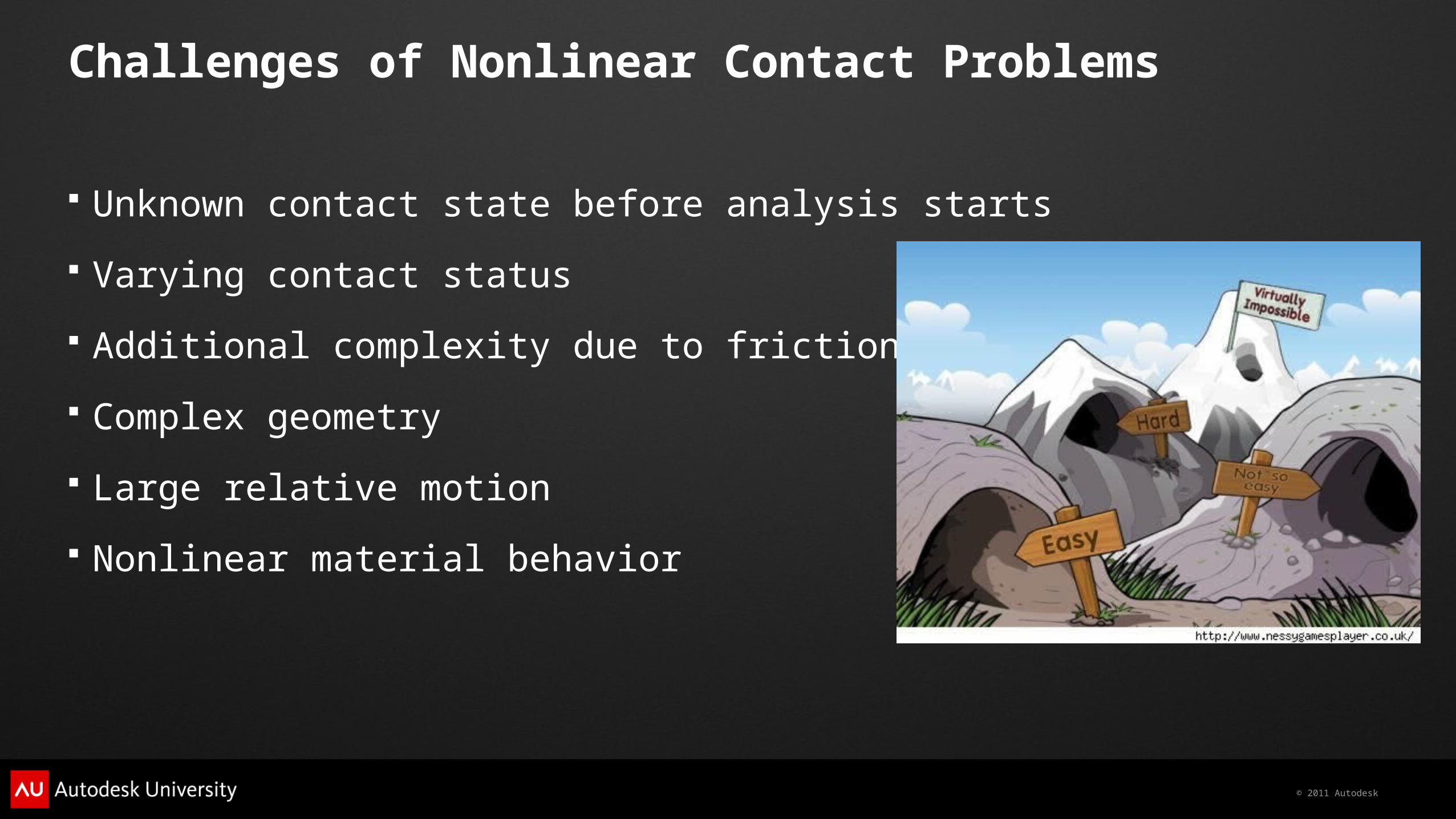
Challenges of Nonlinear Contact Problems
Unknown contact state before analysis starts
Varying contact status
Additional complexity due to friction
Complex geometry
Large relative motion
Nonlinear material behavior

© 2011 Autodesk
Possible warning messages to look for:
For a defined “Surface to Surface” contact pair:** Warning: S-S contact is NOT necessary for contact pair, #! P-S contact is recommended.
For a defined “Point to Surface” contact pair:** Warning: P-S contact is NOT proper for contact pair, #! S-S contact is recommended.
For a defined “Point to Surface” contact pair: 1st and 2nd parts in contact pair, #, should be switched.
Understanding Feedback
Proper contact type
Better accuracy
Better efficiency

© 2011 Autodesk
For parts with element definition of “small displacement”:** Warning: when <MES with Nonlinear Material Models> is used for the models having (general) contact element, general surface contact, or impact planes, <Large deformation> is recommended for all parts.
Understanding Feedback (cont’d)

© 2011 Autodesk
Diagnosing Convergence and Possible Issues
Step level
Number of iterations
Convergence residual
Log file
Summary file

© 2011 Autodesk
Improving Performance
© 2011 Autodesk
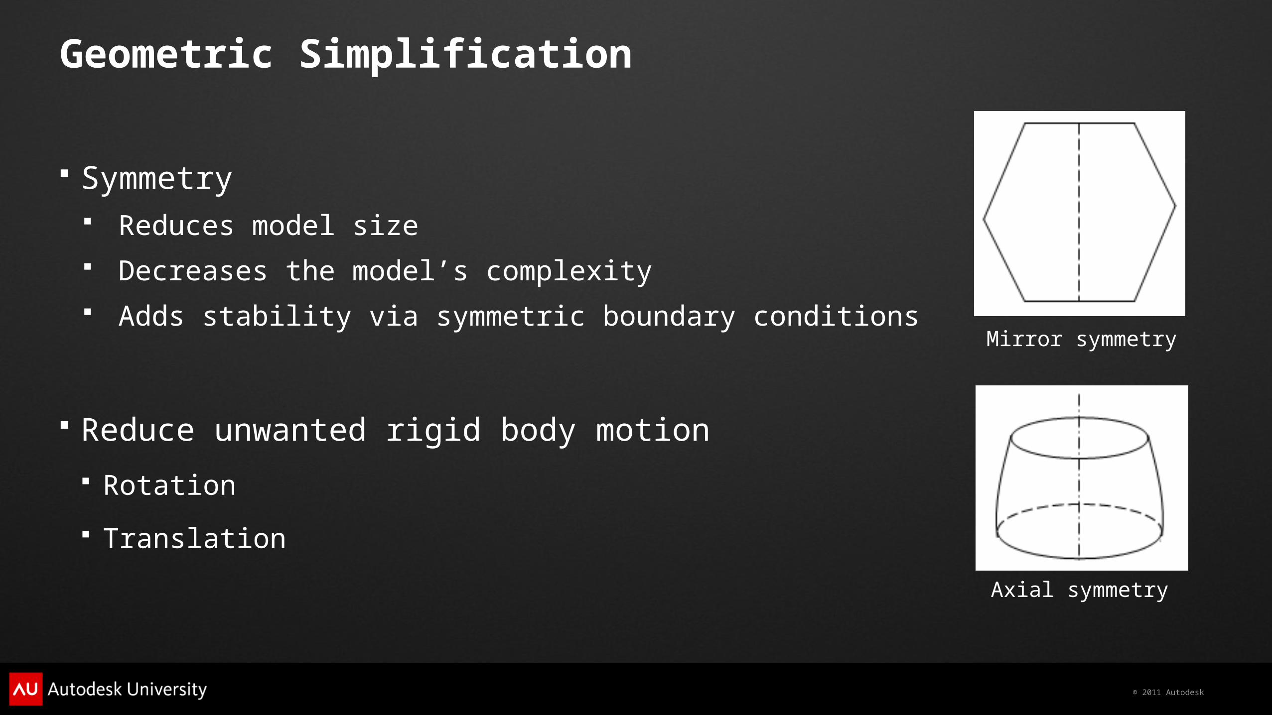
Geometric Simplification
Symmetry Reduces model size Decreases the model’s complexity Adds stability via symmetric boundary conditions
Reduce unwanted rigid body motion Rotation
Translation
Mirror symmetry
Axial symmetry

© 2011 Autodesk
Contact Definition Method – S2S vs. P2P
Contact pairs can be defined as: Surfaces (S2S) Parts (P2P)
Advantages of P2P Contact Easy to define
Disadvantages of P2P Contact Increases model size Increases run time May lead to convergence problems due to inappropriate contact settings

© 2011 Autodesk
Contact Updating Scheme – Auto vs. Never
Contact search Global search Local search
Contact updating “Never” option
Only does global search at very beginning Never updates contact elements for local search The most efficient for cases with small relative motion
“Automatic” option (default) Automatically does global search if needed Update contact elements for local search

© 2011 Autodesk
Options to define contact stiffness User-defined Automatic
Penalty method
Contact Stiffness
dKF CC
© 2011 Autodesk
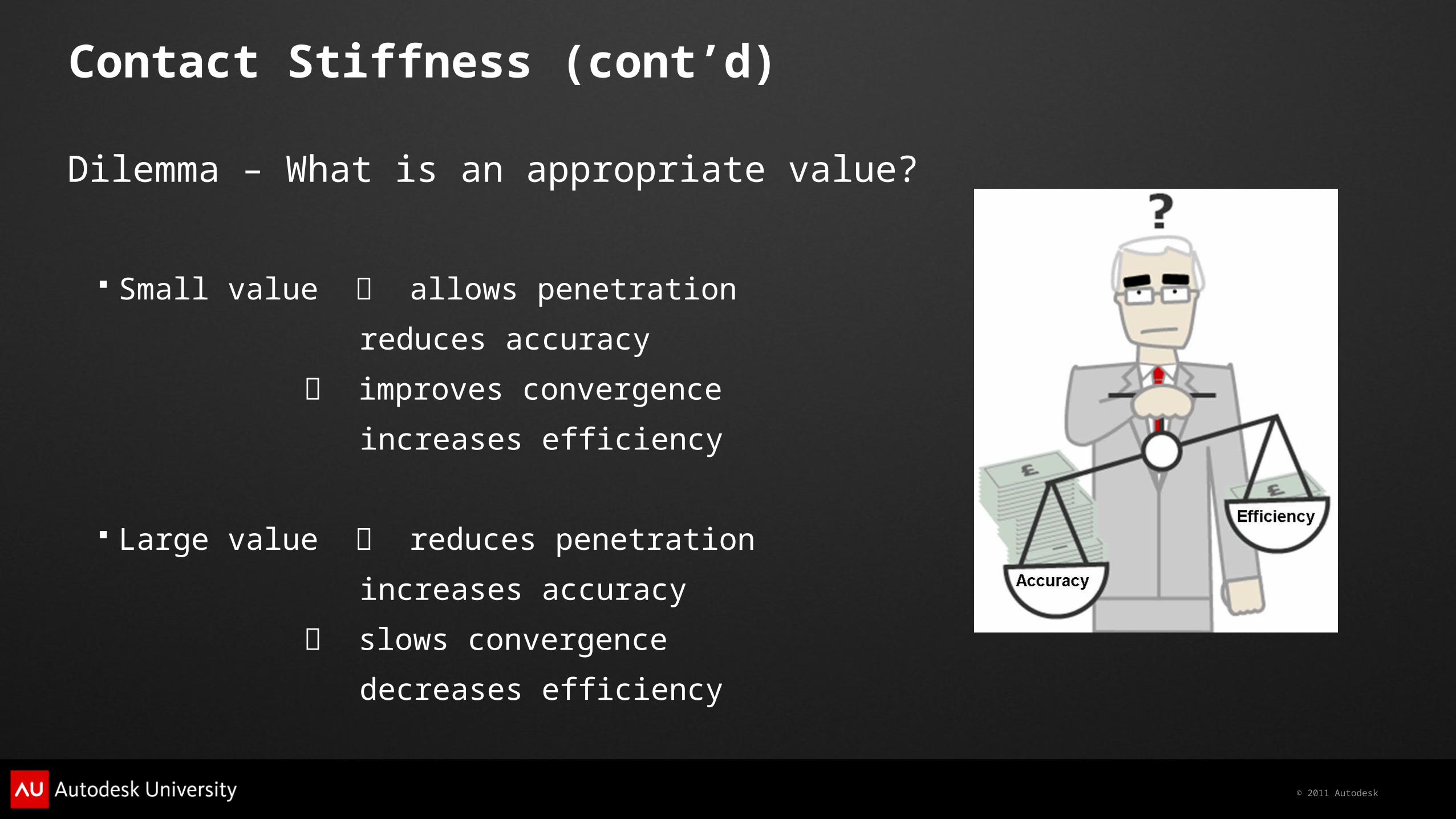
Contact Stiffness (cont’d)
Dilemma – What is an appropriate value?
Small value allows penetration
reduces accuracy
improves convergence
increases efficiency
Large value reduces penetration
increases accuracy
slows convergence
decreases efficiency

© 2011 Autodesk
Contact Stiffness (cont’d)
Estimate a trial value and run analysis• “Automatic” option can be used as a start• Young’s Modulus/(10 to 100) is a good start for “User-defined”
Examine convergence and penetration
Adjust the value based on performance• Increase the value if large penetration occurs• Reduce the value if poor convergence appears
Rerun the analysis

© 2011 Autodesk
Frictional Contact
Application
sff dKF TSCf RatioKK

© 2011 Autodesk
Frictional Contact
Start with default tangential stiffness ratio• The default value of 1.0 is the biggest value accepted• A tangential stiffness ratio of 0.01 is a good starting
Examine convergence and relative sliding motion
Adjust the value: (Tangential stiffness ratio)• Increase the value if large relative motion happens when friction force is small• Reduce the value if poor convergence appears
Rerun the analysis
© 2011 Autodesk
Setting up a Contact and Drop Test Model

© 2011 Autodesk
Example

© 2011 Autodesk
Final Thoughts – Tips and Tricks
Use MES for nonlinear contact analyses
Use “Automatic” when defining the Contact type
Use “Large displacement” for MES analysis type
Monitor convergence via level and residual feedback
Simplify geometry where possible
Stabilize models to prevent unnecessary motion
Use “Never” updating option when small relative motion is present
Use the trial-and-error procedure to adjust contact stiffness
Reduce tangential stiffness ratio to 0.01

© 2011 Autodesk
Autodesk University Session Feedback
Your feedback is very important to Autodesk.
You can complete the session survey on your mobile device, PC, or at a survey station.
Each completed session survey enters you in that day’s drawing for a free AU 2012 pass.
You can help make AU 2012 better!
Complete the AU Conference Survey at a survey station and receive an AU 2011 T-Shirt.

© 2011 Autodesk
Autodesk, AutoCAD* [*if/when mentioned in the pertinent material, followed by an alphabetical list of all other trademarks mentioned in the material] are registered trademarks or trademarks of Autodesk, Inc., and/or its subsidiaries and/or affiliates in the USA and/or other countries. All other brand names, product names, or trademarks belong to their respective holders. Autodesk reserves the right to alter product and services offerings, and specifications and pricing at any time without notice, and is not responsible for typographical or graphical errors that may appear in this document. © 2011 Autodesk, Inc. All rights reserved.