© 2001, cisco systems, inc. ip over mpls. © 2001, cisco systems, inc. qos v1.0—11-2 objectives...
TRANSCRIPT

© 2001, Cisco Systems, Inc.
IP over MPLS

© 2001, Cisco Systems, Inc. QOS v1.0—11-2
ObjectivesObjectives
Upon completing this module, you will be able to: • Describe and configure QoS mechanisms in
frame-mode MPLS networks
• Describe and configure QoS mechanisms in cell-mode MPLS networks
MPLSIntroduction
MPLSIntroduction
© 2001, Cisco Systems, Inc. QOS v1.0—11-3

© 2001, Cisco Systems, Inc. QOS v1.0—11-4
ObjectivesObjectives
Upon completing this lesson, you will be able to: • Describe the basic features of MPLS
• Describe frame-mode MPLS
• Describe cell-mode MPLS
© 2001, Cisco Systems, Inc. QOS v1.0—11-5
Basic MPLS ConceptsBasic MPLS Concepts
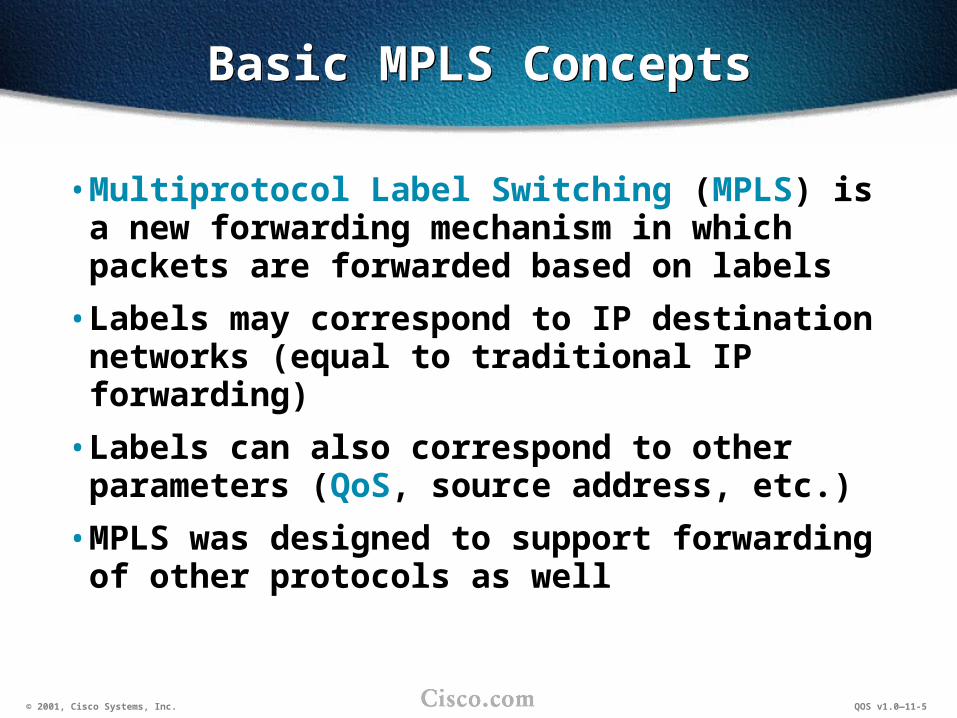
• Multiprotocol Label Switching (MPLS) is a new forwarding mechanism in which packets are forwarded based on labels
• Labels may correspond to IP destination networks (equal to traditional IP forwarding)
• Labels can also correspond to other parameters (QoS, source address, etc.)
• MPLS was designed to support forwarding of other protocols as well

© 2001, Cisco Systems, Inc. QOS v1.0—11-6
MPLS ExampleMPLS Example
• Only edge routers must perform a routing lookup.
• Core routers switch packets based on simple label lookups, and swap labels.
L=5L=5L=3L=3
10.1.1.110.1.1.110.1.1.110.1.1.1
Routing Lookup and
Label Assignment10.0.0.0/8 L=5
Label SwappingL=5 L=3
Label Removal and
Routing Lookup
L=3
© 2001, Cisco Systems, Inc. QOS v1.0—11-7
MPLS vs. IP over ATMMPLS vs. IP over ATM
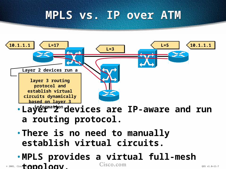
• Layer 2 devices are IP-aware and run a routing protocol.
• There is no need to manually establish virtual circuits.
• MPLS provides a virtual full-mesh topology.
10.1.1.110.1.1.1L=5L=5L=3L=3
L=17L=1710.1.1.110.1.1.1
Layer 2 devices run a layer 3 routing protocol
and establish virtual circuits dynamically based
on layer 3 information.

© 2001, Cisco Systems, Inc. QOS v1.0—11-8
Traffic Engineering with MPLSTraffic Engineering with MPLS
• Traffic can be forwarded based on other parameters (QoS, source, etc.).
• Load sharing across unequal paths can take place.
Secondary OC 48 Link
Large Site A
Large Site B
Small Site C
Primary OC 192 Link

© 2001, Cisco Systems, Inc. QOS v1.0—11-9
MPLS ArchitectureMPLS Architecture
• MPLS has two major components:
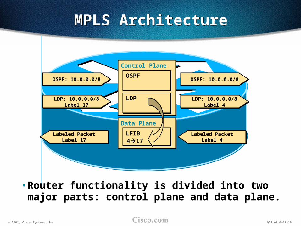
–Control plane–exchanges layer-3 routing information and labels
–Data plane–forwards packets based on labels
• The control plane contains complex mechanisms to exchange routing information (OSPF, EIGRP, IS-IS, RIPBGP, etc.) and labels (TDP, LDP, RIPBGP, RSVP, etc.).
• The control plane maintains the contents of the label switching table (label forwarding information base, or LFIB).
• The data plane has a simple forwarding engine.
© 2001, Cisco Systems, Inc. QOS v1.0—11-10
MPLS ArchitectureMPLS Architecture
• Router functionality is divided into two major parts: control plane and data plane.
Data PlaneData Plane
Control PlaneControl Plane
OSPF: 10.0.0.0/8OSPF: 10.0.0.0/8
LDP: 10.0.0.0/8Label 17
LDP: 10.0.0.0/8Label 17
OSPFOSPF
LDPLDP
LFIBLFIB
LDP: 10.0.0.0/8Label 4
LDP: 10.0.0.0/8Label 4
OSPF: 10.0.0.0/8OSPF: 10.0.0.0/8
417Labeled Packet
Label 4Labeled Packet
Label 4Labeled Packet
Label 17Labeled Packet
Label 17
© 2001, Cisco Systems, Inc. QOS v1.0—11-11
MPLS Modes of OperationMPLS Modes of Operation
• MPLS technology is designed to be Layer 1 and Layer 2 independent.
• MPLS uses a 32-bit label field, which is inserted between Layer 2 and Layer 3 headers (frame mode).
• MPLS over ATM uses the ATM header as the label (cell mode).
© 2001, Cisco Systems, Inc. QOS v1.0—11-12
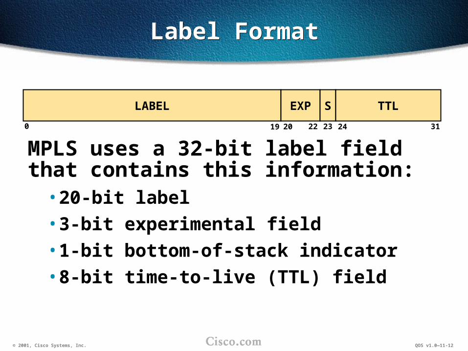
Label FormatLabel Format
MPLS uses a 32-bit label field that contains this information:• 20-bit label
• 3-bit experimental field
• 1-bit bottom-of-stack indicator
• 8-bit time-to-live (TTL) field
LABEL EXP S TTL
0 19 22 23 3120 24

© 2001, Cisco Systems, Inc. QOS v1.0—11-13
Frame Mode MPLSFrame Mode MPLS
FrameHeader
IP Header Payload
Layer 2 Layer 3
FrameHeader
Label IP Header Payload
Layer 2 Layer 2½ Layer 3
Routing Lookup and
Label Assignment
© 2001, Cisco Systems, Inc. QOS v1.0—11-14
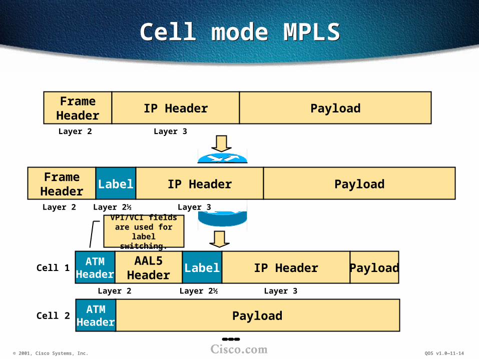
Cell mode MPLSCell mode MPLS
FrameHeader
IP Header Payload
Layer 2 Layer 3
FrameHeader
Label IP Header Payload
Layer 2 Layer 2½ Layer 3
AAL5Header
Label IP Header Payload
Layer 2 Layer 2½ Layer 3
ATMHeader
Cell 1
PayloadATM
HeaderCell 2
VPI/VCI fields are used for label
switching.

© 2001, Cisco Systems, Inc. QOS v1.0—11-15
Label Switch RouterLabel Switch Router
• The label switch router (LSR) primarily forwards labeled packets (label swapping).
• The edge LSR primarily labels IP packets and forwards them into the MPLS domain, or removes labels and forwards IP packets out of the MPLS domain.
MPLS DomainMPLS Domain
Edge LSR
LSR
10.1.1.110.1.1.1 L=3L=3 L=5L=5
L=43L=43L=31L=3120.1.1.120.1.1.1
10.1.1.110.1.1.1
20.1.1.120.1.1.1

© 2001, Cisco Systems, Inc. QOS v1.0—11-16
ATM Label Switch RouterATM Label Switch Router
• An ATM LSR can only forward cells.
• An ATM edge LSR segments packets into cells and forwards them into an MPLS ATM domain, or reassembles cells into packets and forwards them out of an MPLS ATM domain.
MPLS DomainMPLS Domain
ATMEdge LSR
ATMLSR
10.1.1.110.1.1.1 L=1/3L=1/3
L=1/6L=1/620.1.1.120.1.1.1
10.1.1.110.1.1.1
20.1.1.120.1.1.1
L=1/3L=1/3 L=1/3L=1/3 L=1/5L=1/5 L=1/5L=1/5 L=1/5L=1/5
L=1/6L=1/6 L=1/6L=1/6L=1/9L=1/9 L=1/9L=1/9 L=1/9L=1/9

© 2001, Cisco Systems, Inc. QOS v1.0—11-17
Architecture of LSRsArchitecture of LSRs
• LSRs, regardless of the type, perform these three functions:
–Exchange routing information
–Exchange labels
–Forward packets (LSRs and edge LSRs) or cells (ATM LSRs and ATM edge LSRs)
• The first two functions are part of the control plane.
• The last function is part of the data plane.

© 2001, Cisco Systems, Inc. QOS v1.0—11-18
Architecture of LSRs (cont.)Architecture of LSRs (cont.)
LSRs primarily forward labeled packets or cells (ATM LSRs).
LSRLSR
Control PlaneControl Plane
Data PlaneData Plane
Routing ProtocolRouting Protocol
Label Distribution ProtocolLabel Distribution Protocol
Label Forwarding TableLabel Forwarding Table
IP Routing TableIP Routing Table
Exchange ofRouting Information
Exchange ofLabels
Incoming Labeled Packets
Outgoing Labeled Packets

© 2001, Cisco Systems, Inc. QOS v1.0—11-19
Architecture of Edge LSRsArchitecture of Edge LSRs
Note: ATM edge LSRs can only forward cells.
Edge LSREdge LSR
Control planeControl plane
Data planeData plane
Routing ProtocolRouting Protocol
Label Distribution ProtocolLabel Distribution Protocol
Label Forwarding TableLabel Forwarding Table
IP Routing TableIP Routing Table
Exchange ofRouting Information
Exchange ofLabels
Incoming Labeled Packets
Outgoing Labeled Packets
IP Forwarding TableIP Forwarding Table
Incoming IP Packets
Outgoing IP Packets
© 2001, Cisco Systems, Inc. QOS v1.0—11-20
SummarySummary
Upon completing this lesson, you should be able to:• Describe the basic features of MPLS
• Describe frame-mode MPLS
• Describe cell-mode MPLS

© 2001, Cisco Systems, Inc. QOS v1.0—11-21
Lesson ReviewLesson Review
1. What are the main benefits of MPLS?
2. How is an MPLS label encoded into IP packets?
3. How are labels propagated?

© 2001, Cisco Systems, Inc. QOS v1.0—11-22
ObjectivesObjectives
Upon completing this lesson, you will be able to: • Describe the QoS possibilities in networks
using frame-mode MPLS
• Use the MQC to implement QoS with frame-mode MPLS

© 2001, Cisco Systems, Inc. QOS v1.0—11-23
Frame-mode MPLSFrame-mode MPLS
© 2001, Cisco Systems, Inc. QOS v1.0—11-23
© 2001, Cisco Systems, Inc. QOS v1.0—11-24
MPLS QoSMPLS QoS
• MPLS uses labels to make a forwarding decision.
• The MPLS label is inserted between Layer 2 (frame) and Layer 3 (IP packet) headers.
• All Layer 3 information becomes invisible to routers in an MPLS domain.
• Classification in MPLS-enabled networks can be performed on:
–MPLS experimental bits
–MPLS labels (future enhancement)
© 2001, Cisco Systems, Inc. QOS v1.0—11-25
MPLS Label AssignmentMPLS Label Assignment
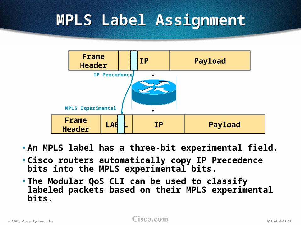
• An MPLS label has a three-bit experimental field.
• Cisco routers automatically copy IP Precedence bits into the MPLS experimental bits.
• The Modular QoS CLI can be used to classify labeled packets based on their MPLS experimental bits.
LABEL IPFrameHeader
FrameHeader
Payload
PayloadIP
IP Precedence
MPLS Experimental

© 2001, Cisco Systems, Inc. QOS v1.0—11-26
MPLS-Aware QoS MechanismsMPLS-Aware QoS Mechanisms
• These QoS mechanisms are MPLS-aware:
–Weighted random early detection (WRED): MPLS experimental bits are used as weight in the same manner as IP Precedence
–Committed access rate (CAR): marking of MPLS experimental bits
–Class-based policing: marking of MPLS experimental bits
–Class-based marking: marking of MPLS experimental bits
• If classification is performed based on MPLS experimental bits, other MQC QoS mechanisms can also be used.

© 2001, Cisco Systems, Inc. QOS v1.0—11-27
Configuring CBWFQ for MPLSConfiguring CBWFQ for MPLS
match mpls experimental expmatch mpls experimental exp
Router(config-cmap)#
• Classifies packets based on MPLS experimental bitsclass-map match-any Gold match ip precedence 3 4 match mpls experimental 3 4!class-map match-any Silver match ip precedence 1 2 match mpls experimental 1 2!policy-map IP+MPLS class Gold bandwidth 3000 class Silver bandwidth 1000!Interface Ethernet0/0 ip address 10.1.1.1 255.255.255.0 mpls ip service-policy output IP+MPLS!
class-map match-any Gold match ip precedence 3 4 match mpls experimental 3 4!class-map match-any Silver match ip precedence 1 2 match mpls experimental 1 2!policy-map IP+MPLS class Gold bandwidth 3000 class Silver bandwidth 1000!Interface Ethernet0/0 ip address 10.1.1.1 255.255.255.0 mpls ip service-policy output IP+MPLS!

© 2001, Cisco Systems, Inc. QOS v1.0—11-28
CAR DiagramCAR Diagram
MeterMeter
Conforms?Conforms?
Set IP Precedence?Set IP Precedence?
Set DSCP?Set DSCP?
Set MPLS Exp.?Set MPLS Exp.?
Set QoS Grp.?Set QoS Grp.?
Mark?Mark?
Transmit?Transmit?Conform or Exceed
Marking Value
Set IP PrecedenceSet IP Precedence
Set DSCPSet DSCP
Set MPLS ExperimentalSet MPLS Experimental
Set QoS GroupSet QoS Group
Continue?Continue?
Yes
Yes
No
No
Forwardor
Enqueue
Go toNext
CAR Command
• Marking depends on whether the packet conforms to or exceeds the QOS policy.
Yes
Yes
Yes
Yes
DropDrop

© 2001, Cisco Systems, Inc. QOS v1.0—11-29
Configuring CAR for MPLSConfiguring CAR for MPLS
rate-limit {input | output} {access-group rate-limit acl} rate BC BE conform-act {set-mpls-exp-transmit exp | set-mpls-exp-continue exp} exceed-act {set-mpls-exp-transmit exp | set-mpls-exp-continue exp}
rate-limit {input | output} {access-group rate-limit acl} rate BC BE conform-act {set-mpls-exp-transmit exp | set-mpls-exp-continue exp} exceed-act {set-mpls-exp-transmit exp | set-mpls-exp-continue exp}
Router(config-if)#
• CAR can mark MPLS packets based on their arrival rate.• CAR supports recursive processing of rate-limit commands. • CAR supports classification based on MPLS experimental bit values by
using the rate-limit access list.• Both conform and exceed actions support other actions: transmit,
continue, drop, set-prec-transmit, set-prec-continue, etc.
interface Serial0/0 ip address 10.1.1.1 255.255.255.252 rate-limit input 64000 2000 2000 conform set-mpls-exp-tr 5 exceed set-mpls-exp-tr 0 rate-limit output 64000 2000 2000 conform set-mpls-exp-tr 5 exceed set-mpls-exp-tr 0!
interface Serial0/0 ip address 10.1.1.1 255.255.255.252 rate-limit input 64000 2000 2000 conform set-mpls-exp-tr 5 exceed set-mpls-exp-tr 0 rate-limit output 64000 2000 2000 conform set-mpls-exp-tr 5 exceed set-mpls-exp-tr 0!
© 2001, Cisco Systems, Inc. QOS v1.0—11-30
Configuring CAR for MPLS (cont.)Configuring CAR for MPLS (cont.)
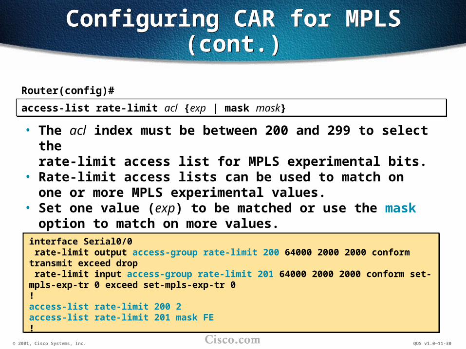
access-list rate-limit acl {exp | mask mask}access-list rate-limit acl {exp | mask mask}
Router(config)#
• The acl index must be between 200 and 299 to select the rate-limit access list for MPLS experimental bits.
• Rate-limit access lists can be used to match on one or more MPLS experimental values.
• Set one value (exp) to be matched or use the mask option to match on more values.
• Each access list can have only one line.interface Serial0/0 rate-limit output access-group rate-limit 200 64000 2000 2000 conform transmit exceed drop rate-limit input access-group rate-limit 201 64000 2000 2000 conform set-mpls-exp-tr 0 exceed set-mpls-exp-tr 0!access-list rate-limit 200 2access-list rate-limit 201 mask FE!
interface Serial0/0 rate-limit output access-group rate-limit 200 64000 2000 2000 conform transmit exceed drop rate-limit input access-group rate-limit 201 64000 2000 2000 conform set-mpls-exp-tr 0 exceed set-mpls-exp-tr 0!access-list rate-limit 200 2access-list rate-limit 201 mask FE!

© 2001, Cisco Systems, Inc. QOS v1.0—11-31
Class-Based PolicingClass-Based Policing
• Class-based policing is similar to CAR except that:
– It uses the Modular QoS CLI for classification
– It supports three different actions (conform, exceed, and violate)
– It does not support recursive processing of packets
© 2001, Cisco Systems, Inc. QOS v1.0—11-32
Configuring Class-Based Policing for MPLS
Configuring Class-Based Policing for MPLS
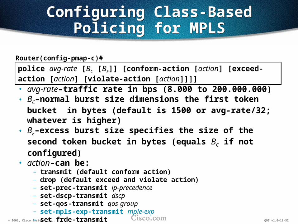
police avg-rate [BC [BE]] [conform-action [action] [exceed-action [action] [violate-action [action]]]]
police avg-rate [BC [BE]] [conform-action [action] [exceed-action [action] [violate-action [action]]]]
Router(config-pmap-c)#
• avg-rate–traffic rate in bps (8.000 to 200.000.000)• BC–normal burst size dimensions the first token bucket in bytes
(default is 1500 or avg-rate/32; whatever is higher)• BE–excess burst size specifies the size of the second token
bucket in bytes (equals BC if not configured)• action–can be:
– transmit (default conform action)– drop (default exceed and violate action)– set-prec-transmit ip-precedence– set-dscp-transmit dscp– set-qos-transmit qos-group– set-mpls-exp-transmit mple-exp– set frde-transmit – set-clp-transmit

© 2001, Cisco Systems, Inc. QOS v1.0—11-33
Class-Based MarkingClass-Based Marking
• Class-based marking can be used to mark labeled packets by setting the MPLS experimental bits
• MPLS experimental bits can currently be set only on input
• DSCP should be translated to IP Precedence prior to entry into an MPLS domain

© 2001, Cisco Systems, Inc. QOS v1.0—11-34
Configuring MPLS MarkingConfiguring MPLS Marking
set mpls experimental exp-bitsset mpls experimental exp-bits
Router(config-pmap-c)#
• Mark labeled packets with the specified value (0 to 7).• MPLS marking can be used only on input.
policy-map SetMPLS class Class1 qos-group 1 set mpls experimental 1 class Class2 qos-group 2 set mpls experimental 2 class Class3 qos-group 2 set mpls experimental 3!
policy-map SetMPLS class Class1 qos-group 1 set mpls experimental 1 class Class2 qos-group 2 set mpls experimental 2 class Class3 qos-group 2 set mpls experimental 3!
© 2001, Cisco Systems, Inc. QOS v1.0—11-35
MPLS TranslationCase Study
MPLS TranslationCase Study
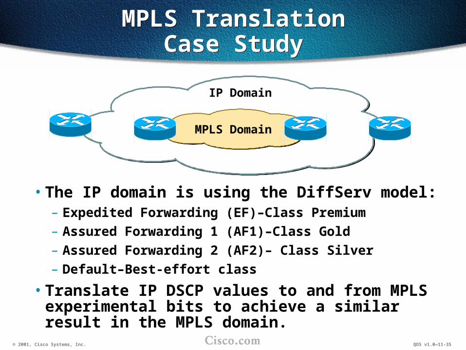
• The IP domain is using the DiffServ model:– Expedited Forwarding (EF)–Class Premium
– Assured Forwarding 1 (AF1)–Class Gold
– Assured Forwarding 2 (AF2)– Class Silver
– Default–Best-effort class
• Translate IP DSCP values to and from MPLS experimental bits to achieve a similar result in the MPLS domain.
MPLS Domain
IP Domain

© 2001, Cisco Systems, Inc. QOS v1.0—11-36
MPLS Translation Case Study DesignMPLS Translation
Case Study Design
IP DSCP MPLSExperimental
EF 5AF1 low-drop 4AF1 medium-drop 4AF1 high-drop 3AF2 low-drop 2AF2 medium-drop 2AF2 high-drop 1Default 0
MPLS DomainIP Domain
DSCP MPLS Experimental
IP PrecedenceQoS Group

© 2001, Cisco Systems, Inc. QOS v1.0—11-37
MPLS Translation Case Study Implementation
MPLS Translation Case Study Implementation
MPLS DomainIP Domain
DSCP MPLS Experimental
IP Precedence
class-map EF match ip dscp efclass-map AF1LD match ip dscp af11 af12class-map AF1HD match ip dscp af13!policy-map DSCP2prec class EF set ip precedence 5 class AF1LD set ip precedence 4 class AF1HD set ip precedence 3!
class-map EF match ip dscp efclass-map AF1LD match ip dscp af11 af12class-map AF1HD match ip dscp af13!policy-map DSCP2prec class EF set ip precedence 5 class AF1LD set ip precedence 4 class AF1HD set ip precedence 3!
interface Serial5/1/0 service-policy input DSCP2prec!
interface Serial5/1/0 service-policy input DSCP2prec!

© 2001, Cisco Systems, Inc. QOS v1.0—11-38
MPLS Translation Case Study Implementation (cont.)
MPLS Translation Case Study Implementation (cont.)
MPLS DomainIP Domain
DSCP MPLS Experimental
QoS Group
class-map match-any MPLS5 match mpls exp 5 match ip precedence 5class-map match-any MPLS4 match mpls exp 4 match ip precedence 4class-map match-any MPLS3 match mpls exp 3 match ip precedence 3!policy-map MPLS2QoS class MPLS5 set qos-group 5 class MPLS4 set qos-group 4 class MPLS3 set qos-group 3
class-map match-any MPLS5 match mpls exp 5 match ip precedence 5class-map match-any MPLS4 match mpls exp 4 match ip precedence 4class-map match-any MPLS3 match mpls exp 3 match ip precedence 3!policy-map MPLS2QoS class MPLS5 set qos-group 5 class MPLS4 set qos-group 4 class MPLS3 set qos-group 3
class-map QoS5 match qos-group 5class-map QoS4 match qos-group 4class-map QoS3 match qos-group 3!policy-map QoS2DSCP class QoS5 set ip dscp ef class QoS4 set ip dscp af12 class QoS3 set ip dscp af13!
class-map QoS5 match qos-group 5class-map QoS4 match qos-group 4class-map QoS3 match qos-group 3!policy-map QoS2DSCP class QoS5 set ip dscp ef class QoS4 set ip dscp af12 class QoS3 set ip dscp af13!
interface Serial5/1/1 service-policy input MPLS2QoS!interface Serial5/1/0 service-policy output QoS2DSCP

© 2001, Cisco Systems, Inc. QOS v1.0—11-39
Lesson ReviewLesson Review
1. Which MPLS parameter is used for classification and marking?
2. What is the default value of the MPLS experimental bits?
3. Which QoS mechanisms can be used to set MPLS experimental bits?

© 2001, Cisco Systems, Inc. QOS v1.0—11-40
SummarySummary
Upon completing this lesson, you should be able to:• Describe the QoS possibilities in networks
using frame-mode MPLS
• Use the MQC to implement QoS with frame-mode MPLS

© 2001, Cisco Systems, Inc. QOS v1.0—11-41
Cell-mode MPLSCell-mode MPLS
© 2001, Cisco Systems, Inc. QOS v1.0—11-41
© 2001, Cisco Systems, Inc. QOS v1.0—11-42
ObjectivesObjectives
Upon completing this lesson, you will be able to: • Describe QoS features available with
cell-mode MPLS
• Implement QoS on interfaces using cell-mode MPLS

© 2001, Cisco Systems, Inc. QOS v1.0—11-43
Cell-Mode MPLS QoSCell-Mode MPLS QoS
• Classes are encoded with MPLS experimental bits.
• Cell-mode MPLS uses the VPI/VCI fields as labels for forwarding.
• ATM switches are not capable of looking into the frame-mode label where the experimental bits are.
• QoS is implemented using up to four parallel virtual circuits (label-switched paths).
© 2001, Cisco Systems, Inc. QOS v1.0—11-44
Cell-Mode MPLSCell-Mode MPLS
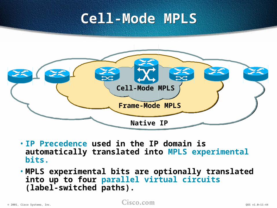
• IP Precedence used in the IP domain is automatically translated into MPLS experimental bits.
• MPLS experimental bits are optionally translated into up to four parallel virtual circuits (label-switched paths).
Native IP
Frame-Mode MPLS
Cell-Mode MPLS

© 2001, Cisco Systems, Inc. QOS v1.0—11-45
Configuring Multi-VCConfiguring Multi-VC
mpls atm multi-vcmpls atm multi-vc
Router(config-if)#
• The command enables multi-VC operation of cell-mode MPLS.
• Eight MPLS experimental values are mapped to four virtual circuits.
• The class is determined by the two least significant MPLS experimental bits.
• Default mapping is similar to classification of distributed ToS-based WFQ.
• Default mapping can be replaced using the cos-map command.
MPLS Exp. VC
0 Available1 Standard2 Premium3 Control4 Available5 Standard6 Premium7 Control

© 2001, Cisco Systems, Inc. QOS v1.0—11-46
Configuring CoS MappingConfiguring CoS Mapping
mpls cos-map numbermpls cos-map number
Router(config)#
• Create a CoS map• Allowed values are from 1 to 255
class class {available | control | premium | standard}class class {available | control | premium | standard}
Router(config-mpls-cos-map)#
• Assigns a class to one of four virtual circuits• Class values can range from 0 to 3
mpls prefix-map pfmap access-list acl cos-map cos-mapmpls prefix-map pfmap access-list acl cos-map cos-map
Router(config)#
• Uses CoS map cos-map for all destinations permitted by access list acl
© 2001, Cisco Systems, Inc. QOS v1.0—11-47
Configuration ExampleConfiguration Example
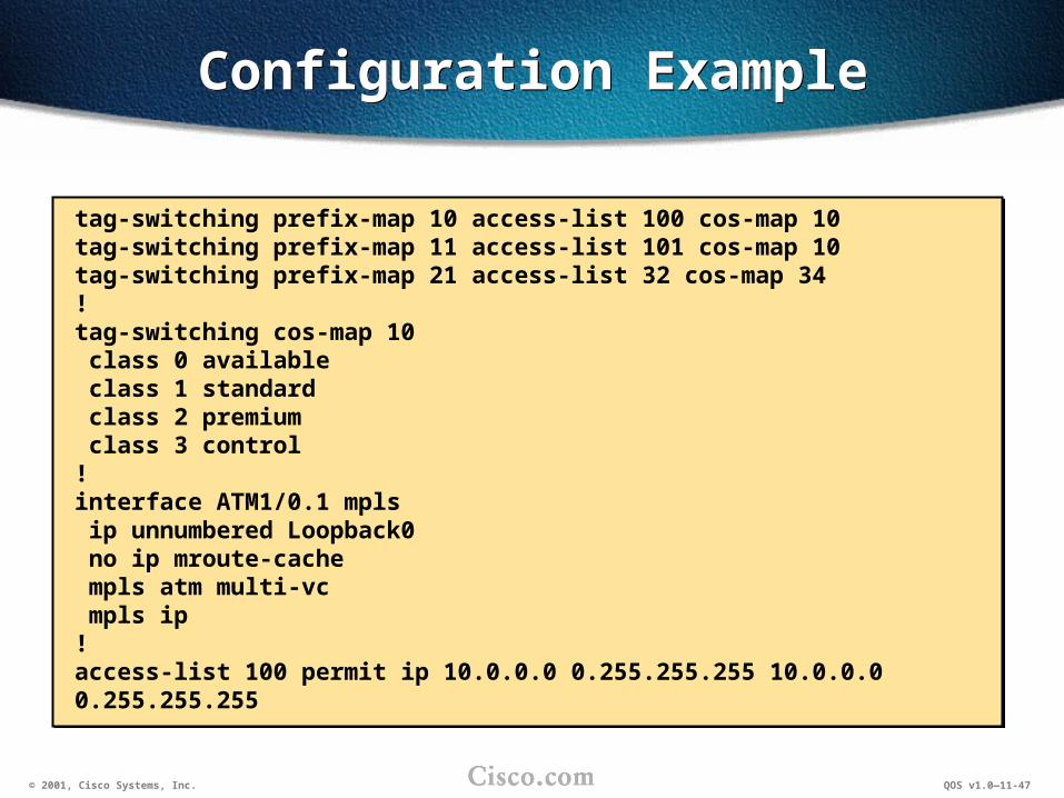
tag-switching prefix-map 10 access-list 100 cos-map 10tag-switching prefix-map 11 access-list 101 cos-map 10tag-switching prefix-map 21 access-list 32 cos-map 34!tag-switching cos-map 10 class 0 available class 1 standard class 2 premium class 3 control!interface ATM1/0.1 mpls ip unnumbered Loopback0 no ip mroute-cache mpls atm multi-vc mpls ip!access-list 100 permit ip 10.0.0.0 0.255.255.255 10.0.0.0 0.255.255.255
tag-switching prefix-map 10 access-list 100 cos-map 10tag-switching prefix-map 11 access-list 101 cos-map 10tag-switching prefix-map 21 access-list 32 cos-map 34!tag-switching cos-map 10 class 0 available class 1 standard class 2 premium class 3 control!interface ATM1/0.1 mpls ip unnumbered Loopback0 no ip mroute-cache mpls atm multi-vc mpls ip!access-list 100 permit ip 10.0.0.0 0.255.255.255 10.0.0.0 0.255.255.255

© 2001, Cisco Systems, Inc. QOS v1.0—11-48
Monitoring and Troubleshooting Cell-Mode MPLS
Monitoring and Troubleshooting Cell-Mode MPLS
show mpls cos-map [cos-map]show mpls cos-map [cos-map]
Router#
• Lists all configured CoS maps
Router#show mpls cos-map 10cos-map 10 class tag-VC 3 control 2 premium 1 standard 0 availableRouter#
Router#show mpls cos-map 10cos-map 10 class tag-VC 3 control 2 premium 1 standard 0 availableRouter#

© 2001, Cisco Systems, Inc. QOS v1.0—11-49
Monitoring and Troubleshooting Cell-Mode MPLS (cont.)
Monitoring and Troubleshooting Cell-Mode MPLS (cont.)
show mpls prefix-map [prefix-map]show mpls prefix-map [prefix-map]
Router#
• Lists all configured prefix maps
Router#show mpls prefix-mapprefix-map 10 access-list 100 cos-map 10prefix-map 11 access-list 101 cos-map 10 Warning: In prefix-map 11, acl 101 is not configuredprefix-map 21 access-list 32 cos-map 34 Warning: In prefix-map 21, acl 32 and cos-map 34 are not configuredRouter#
Router#show mpls prefix-mapprefix-map 10 access-list 100 cos-map 10prefix-map 11 access-list 101 cos-map 10 Warning: In prefix-map 11, acl 101 is not configuredprefix-map 21 access-list 32 cos-map 34 Warning: In prefix-map 21, acl 32 and cos-map 34 are not configuredRouter#

© 2001, Cisco Systems, Inc. QOS v1.0—11-50
SummarySummary
Upon completing this lesson, you should be able to:• Describe QoS features available with
cell-mode MPLS
• Implement QoS on interfaces using cell-mode MPLS

© 2001, Cisco Systems, Inc. QOS v1.0—11-51
Lesson ReviewLesson Review
1. How is differentiated QoS implemented on MPLS-enabled ATM interfaces?
2. What information is used for classification in cell-mode MPLS?

© 2001, Cisco Systems, Inc. QOS v1.0—11-52
SummarySummary
Upon completing this module, you should be able to:• Describe and configure QoS mechanisms in
frame-mode MPLS networks
• Describe and configure QoS mechanisms in cell-mode MPLS networks

© 2001, Cisco Systems, Inc. IP QoS IP over MPLS