( / 14 1e @110 @210 ci>3l0 'a ib f- 20
TRANSCRIPT

US006008618A
Ulllted States Patent [19] [11] Patent Number: 6,008,618 Bose et al. [45] Date of Patent: *Dec. 28, 1999
[54] ZERO SPEED START-UP FOR A SPEED 5,629,597 5/1997 Imanaka ................................ .. 318/805 SENSORLESS INDUCTION MOTOR DRIVE 5,631,819 5/1997 Masaki et a1- -- -
5,635,811 6/1997 Rebhan et a1. ..
[75] Inventors: Bima] Kumar Bose, Knoxville, Tenn; 5,729,113 3/1998 Jansen et a1. ......................... .. 318/799
Nitinkumar Ratilal Patel, Long Beach, OTHER PUBLICATIONS Calif.; Kaushik Rajashekara, Carmel, Ind B.K.Bose, M.G.Sirnoes, D.R.Crecelius, K. Rajashekara and
R.Martin, “Speed Sensorless Hybrid Vector Controlled [73] Assignee: General Motors Corporation, Detroit, Induction Motor Drive”, COIlf- R60 IEEE—IAS Annual
Mich. Meeting, pp. 137—143. X.Xu, R.W.DeDonker and D.W.Novotny, “A Stator Flux
[ * ] Notice: This patent issued on a continued pros- Oriented Induction Motor Drive”, Conf. Rec. IEEE—PESC, ecution application ?led under 37 CFR pp. 870—876, 1988. 1.53(d), and is subject to the tWenty year B.K.Bose, PoWer Electronics and AC Drives, Prentice Hall, patent terrn provisions of 35 U.S.C. 1986.
154(21)(2)' Primary Examiner—Paul Ip Attorney, Agent, or Firm—Margaret A. DobroWitsky
[21] Appl. No.: 08/979,021 _ [57] ABSTRACT
[22] Filed: Nov. 26, 1997 An induction motor drive uses direct vector control for Zero
6 .
[51] Int. Cl. ................................ .. H02P 7/00, H02P 5/40 Speed Start up‘ According to the invention, a Speed Sensor_ [52] US. Cl. ........................ .. 318/811; 318/805; 318/800; less induction motor is Controlled at all speeds, including
_ 318/808 Zero or substantially Zero speed, using direct vector control. [58] Field of Search ................................... .. 318/799—832, In Order to utilize direct Vector Control at all speeds, it is
318/778, 779; 363/132, 41> 137 necessary to derive accurate stator ?ux vectors at all speeds. _ This is accomplished in the present invention by calculating
[56] References Clted tWo sets of stator ?ux vectors in diverse rnanners. A?rst set
us PATENT DOCUMENTS of ?ux vectors is derived from measured stator terminal voltage quantities, and a second set of ?ux vectors is derived
Dreiseitl Ct 8.1. ...................... .. from measured Stator Current quantities' The ?rst Set of ?ux
1;; SB1aS_°hkte ettall' ' vectors is valid at non-Zero speed and the second set of ?ux , , ugimo 0 e a . - - - -
571447564 9/1992 Naidu et a1‘ ~~~~ n 364/494 vectors is vlalid at substegntitally Zero speedfTéie direct vector 5 481 172 1/1996 Minowa et a1‘ n 318/8OO contro ut1 1Zes one o t e tWo sets 0' ‘11X ‘vectors in 5’5O2’360 3/1996 Kerkman et a1_ _ 318/8O5 accordance With predetermined criteria indicative of Zero 5,532,571 7/1996 Masaki et a1. 3123/2309 and non-Zero Speed Conditions 5,585,709 12/1996 Jansen et a1. . 318/807 5,619,114 4/1997 Blasko .................................. .. 318/812 11 Claims, 8 Drawing Sheets
11 x 13 x 12 a
DC BRIDGE b I POWER INVERTER {/ \ MOTOR
( / 14 1e 10 @1111 @2141 ‘Pal-11 ‘5 Va Vb V0 17
@110 @210 CI>3L0 ‘a ib F- 20
26 INVERTER LOW PASS FILTER CONTROL AND 34> -—> 2(1)
24 A 1' ’’’’’’’ i i W
\A D s F’ 1 ] 'NLL ] ] vs Vs I s i s 1 1 24 qs ds qs ds 1 L _ \ 1 1 l \ \ /
25 1 1 K’ 1 1
L1» 1 A D c 1 1
I l 28 A]: D s P F : r
l _ E E E 1 . E E _ _ _ J '
24 B {?es “98


U.S. Patent Dec. 23, 1999 Sheet 4 of8 6,008,618
T S S S S
f F’dsf l‘l’dsol ‘Pqsf l q’qso f ————— ——\
L P F
L_¢h
I92; 1 93; was was FIG. 5
601 605 607
IS F A f f 609 FUZZY ATss 1 ATss Ts
we _ ESTIMATOR T I+Ts RS=RSO+ CXRSO (T625)
603 A‘
f T TA AMBIENT
‘(J TEIvIPRATuRE FIG- 6
BACKGROUND DSP1 /DSP2
V
- INITIALIZE 301 — PoINTERs
- vARIABLEs l - FLAGS
— INVERTER CONTROL
- ESTABLISH sERIAL COMMUNICATION - cALIBRATE ADC
7" 303 FIG_ 7 WAIT #XJ
4

U.S. Patent Dec. 28, 1999 Sheet 5 of8 6,008,618
(HARDWARE INTERRUPT DSP 1 / DSP 2 USP 1 I USP 2 431
I I J 401 WRITE TO INVERTER \ ’ SERIAL LINK DATA K _v * CONTROL TRANSFER 433
as I J 'vds CALCULATE .9* -PHASE & NON PHASE
8 COMPENSATED UNIT 403 I VECTORS \, SERIAL LINK DATA -DEvELOFED TORQUE T9 435
TRANSFER 406 < I IINvERSE vECTOR ROTATION STATOR FLUx ESTIMATION I
- ZS FIG. 4 437 - HS FIG. 3 CALCULATE I dq J
- FTASK 1 < 439 407 I I L STATOR FLUX TRANSITION ITOROUE CONTROL LOOP I-1
f (We' Te) I 441 409 I I FLUX CONTROL LOOP |-_J L L—¢h COMPENSATION I
411 I SYNCHRONOUS CURRENT CALCULATE CONTROL LOOP
L -STATOR FLUX ANGLE 96 L - STATOR FLUX ‘I’ MAGNITUDE S 442
-sTATOR ELECTRICAL we FREQUENCY w 443 445
' SLIP FREQUENCY (JOSI j V Y TASK 3 COUNTER
413 I, Y 415 =10,000? >— TASK 2 NTER N I’ =C8O?U >j 2 SET TASK a
N SET TASK 2 449 COLLNJER 419 COUNTER
: 1 V
w I I INCREMENT COUNTER I I INCREMENT COUNTER I II
II 451 ‘ TRIGGER A TRIGGER T TASK 3
421 \ ‘ TASK 2 V I
I ENABLE ADC | ) I ENABLE ADC I S ‘ 417 II RETURN 447 FIG. 8 RETURN

U.S. Patent Dec. 28, 1999 Sheet 6 of8 6,008,618
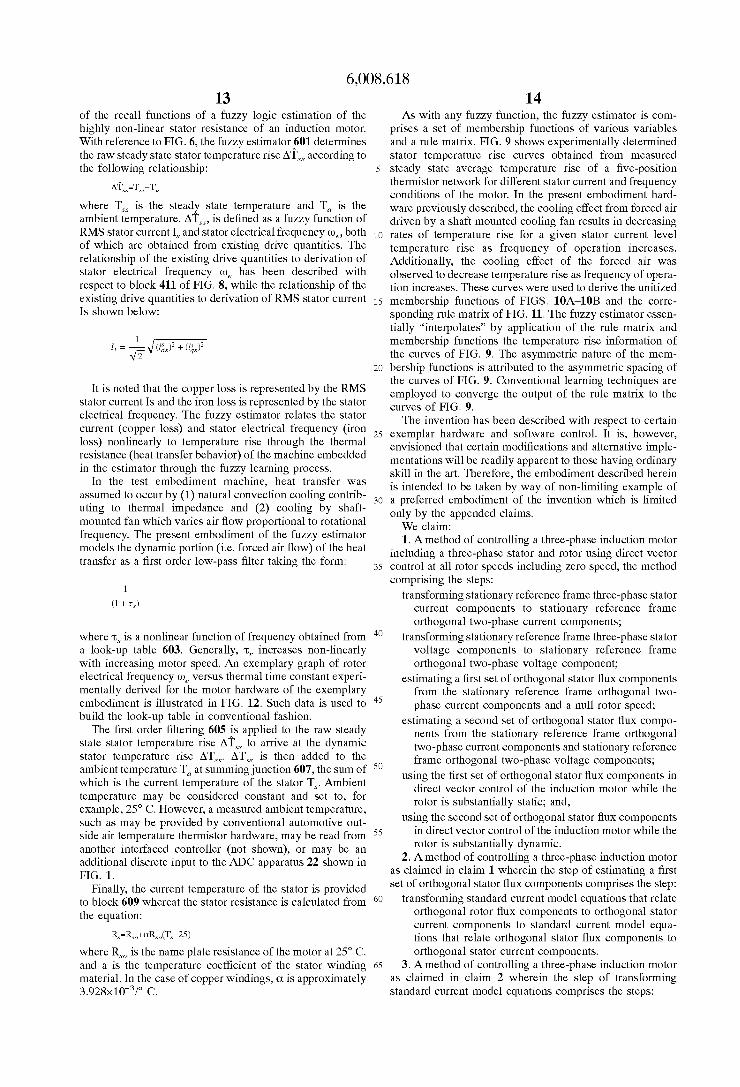
STATOR CURRENT IS (A)
FIG. 9

U.S. Patent Dec. 28, 1999 Sheet 7 of8 6,008,618
V
0 015 1' FREQUENCY
FIG. 10A
VS SS SM SB MM BS BM VB
0 015 T sTAToR CURRENT
FIG. 10B
V
0 015 1' STEADY STATE TEMP. RISE
FIG. 10C

U.S. Patent
THERMAL TIME CONSTANT
Dec. 28, 1999 Sheet 8 0f 8 6,008,618
VS SS SB BS BM BB VB
VS VS W8 W8 W8 W8 W8 WS
SS SS SS VS VS WS WS WS WS
SM SM SM SS SS VS VS W8 W8
SB SB SB SM SM SS SS VS VS
MM M SB SB SM SM SS SS
MM BS MM M SB SB SM SM
BS BB BM MM MM M M SB SM
BM VB BB BM BS BS MM SB
VB WB VB BB BM BM BS MM
650
FIG. 11
600-
550
500 ——
450 -—
400 —
350 l
500 1000 I
FREQUENCY
FIG. 12
1500 2000 2500 3000 3500

6,008,618 1
ZERO SPEED START-UP FOR A SPEED SENSORLESS INDUCTION MOTOR DRIVE
TECHNICAL FIELD
The present invention is related to electric motor drive controls.
BACKGROUND OF THE INVENTION
The technical ?eld of this invention is induction motor controls. In recent years the advent of modern poWer elec tronics has substantially changed the motor and controller hardWare used in traction control or electric vehicle appli cations. DC motors have been very popular in such appli cations in the past because of their characteristic high torque at Zero speed and because the decoupled ?eld and armature currents alloW independent control of either the ?eld ?ux or the output motor torque and provide fast response. HoWever, DC motors have the disadvantages of loWer machine ef? ciencies and the high maintenance that accompanies the use of brushes.
The disadvantages of DC motors can be eliminated by the use of an AC induction motor With an IGBT inverter. AC induction motors are robust since they use no brushes or commutators and are capable of four quadrant operation using a variable frequency variable voltage drive control. The use of vector control techniques alloWs the ?ux pro ducing component and torque producing component of motor current to be decoupled to produce a motor response like that of a DC motor.
Vector control for induction motors is generally classi?ed as indirect vector control (IVC) or direct vector control (DVC). For high performance industrial motor control and electric vehicle applications, indirect vector control using a rotor shaft speed encoder is becoming very popular. With indirect vector control, an induction motor can be operated at any point in the torque-speed plane, from Zero speed to the ?eld-Weakening region. HoWever, the motor parameters may vary, Which causes ?ux-torque coupling problems and degrades control. In addition, this method requires a speed sensor on the motor shaft and feed-forWard slip frequency signals for the required generation of unit vectors. The speed sensor is undesirable because it is expensive and can be unreliable.
Direct vector control generates the unit vectors from ?ux coils or from the motor terminal voltages and currents, and no speed sensor is required. Direct vector control With stator ?ux orientation can reduce the problems caused by varying motor parameters; but it has been dif?cult to operate the motor near Zero speed, and self starting of the motor is impossible. The loWer speed range in direct vector control has recently been extended by using stator ?ux orientation and an observer method of ?ux computation. The motor could be started by a volts/hertZ scalar control and then converted into direct vector control; but this start-up method provides inferior performance.
SUMMARY OF THE INVENTION
The present invention overcomes the problems of oper ating a speed sensorless induction motor at Zero or substan tially Zero speed. According to the invention, a speed sensorless induction motor is controlled at all speeds, including Zero or substantially Zero speed, using direct vector control. In order to utiliZe direct vector control at all speeds, it is necessary to derive accurate stator ?ux vectors at all speeds. This is accomplished in the present invention
10
15
25
45
55
65
2 by calculating tWo sets of stator ?ux vectors in diverse manners. A ?rst set of ?ux vectors is derived from measured stator terminal voltage quantities, and a second set of ?ux vectors is derived from measured stator current quantities. The ?rst set of ?ux vectors is valid at non-Zero speed and the second set of ?ux vectors is valid at substantially Zero speed. The direct vector control utiliZes one of the tWo sets of ?ux vectors in accordance With predetermined criteria indicative of Zero and non-Zero speed conditions.
BRIEF DESCRIPTION OF THE DRAWINGS
FIG. 1 is a-block and schematic diagram of an induction motor system according to the invention.
FIG. 2 is a functional block diagram of the DSP block of the induction motor system shoWn in FIG. 1.
FIG. 3 is a functional block diagram of the high speed (HS) stator ?ux estimator of the DSP block shoWn in FIG. 2.
FIG. 4 is a functional block diagram of the Zero speed (ZS) stator ?ux estimator of the DSP block shoWn in FIG. 2.
FIG. 5 is a functional block diagram of the ?ux selector and compensator of the DSP block shoWn in FIG. 2.
FIG. 6 is a functional block diagram of the stator resis tance (Rs) estimator of the DSP block shoWn in FIG. 2.
FIGS. 7 and 8 are How charts illustrating the operation of the apparatus of FIG. 1.
FIG. 9 is a set of curves for different operational frequen cies of stator current versu measured stator temperature rise used for deriving the stator resistance estimator block shoWn in FIG. 6.
FIGS. 10A—10C are unitiZed membership functions for frequency, stator current and temperature rise derived from the set of curves shoWn in FIG. 9.
FIG. 11 is a rule matrix derived from the membership functions and curves shoWn in FIGS. 10A—10C and FIG. 9, respectively.
FIG. 12 is an exemplary graph of rotor electrical fre quency we versus thermal time constant experimentally derived for the motor hardWare of the embodiment.
DESCRIPTION OF THE PREFERRED EMBODIMENT
FIG. 1 shoWs a motor With a hybrid vector control system according to this invention. A DC poWer supply 10 feeds a voltage fed, PWM, bridge inverter 11 that generates a variable voltage, variable frequency AC supply for a three phase induction motor 12. DC poWer supply 10 may be a battery, especially in an electric vehicle application, but may be any other DC supply for industrial and other stationary applications. In a test embodiment, a peak 100 KW IGBT inverter Was used to drive a Reliance ® 5 horsepoWer industrial induction motor.
Motor terminals a, b and c of lines 13, 14 and 15 are connected to provide terminal voltage signals Va, Vb and VC to a loW pass ?lter and three phase to tWo phase (3CIDQZCIJ) conversion apparatus 20. Likewise, Nana ® Hall effect current sensors 16 and 17, responsive to currents in lines 13 and 14, provide phase current signals id and ib, respectively, to apparatus 20.
In apparatus 20, the three phase terminal voltage signals Va, Vb and VC and current signals id and ib are ?ltered to remove harmonics and converted into the equivalent tWo phase orthogonal voltage and current vector component quantities in the stationary d-q reference frame Vdss, Vqss,

6,008,618 3
id; and iqss. Conversion of the three phase motor terminal voltage and current signals Va, Vb, VC, id and ib to tWo phase orthogonal voltage and current vector component signals Vdss, Vqss, i d; and iqss in the stationary d-q reference frame is accomplished according to the folloWing Well knoWn relationships:
These functions are performed in conjunction With appro priate ?ltering as described in United States patent applica tion corresponding to Attorney docket No. H-181,981 assigned to General Motors Corporation and incorporated by reference herein.
Since further operations on the analog output quantities of apparatus 20 Will be performed in a digital signal processor (DSP) 24, the quantities Vdss, Vqss, i d; and iqss are converted to digital format in an analog to digital converter (ADC) 22. Likewise provided to ADC 22 are eXternal control signals 11)’: and i*qs Which represent, respectively, the commanded stator ?uX and the commanded torque current in the syn chronous frame. ADC 22 communicates With DSP 24 and an inverter
control 26 via a digital communication bus 28. In the present embodiment, the DSP 24 actually includes a pair of DSPs 24A and 24B interfacing via serial link 25. Each of the DSPs includes a pair of serial ports, each of Which is con?gured to transmit or receive data to or from the other DSP, to provide this serial link. TWo DSPs advantageously alloW for improved processing speed and throughput advantages Which Will become apparent beloW. Similarly, ADC actually includes a pair of ADC units though not separately illus trated. The input quantities from ADC 22 are processed in DSP 24 to produce commanded synchronous stator voltages V*d5 and V*qs and a commanded stator ?uX angle 6*e, all of Which are output to inverter control 26. From these commands, inverter control 26 generates commanded ter minal voltages in the form of PWM signals (1)1 HI, (1)1 LO, (pm, ¢2LO, (1)3 HI, and (1)3 LO, Which are applied to bridge inverter 11.
FIG. 2 shoWs a functional block diagram of the control algorithm performed in DSP 24. The input stationary refer ence frame d-q voltages and currents Vdss, Vqss, id; and iqss and stator electrical frequency and stator resistance we and R5 are provided to high speed (HS) stator ?uX estimator 30, in Which they are used to derive orthogonal HS stator ?uX components \PdSfS and ‘P615; in the stationary d-q reference frame. Since the hardWare loW-pass ?ltering performed at block 20 of FIG. 1 may be more than negligible at non-Zero speeds, HS stator ?uX estimator 30 actively adjusts the ?uX components \PdSfS and 1I'qSfS as later described in further detail With respect to FIG. 3.
Only the input stationary reference frame d-q currents i d; and iqss and a null rotor frequency w, are provided to the Zero speed stator ?uX estimator 33, in Which they are used to derive orthogonal ZS stator ?uX components and \PdwS and ‘P615; and in the stationary d-q reference frame. Since the hardWare loW-pass ?ltering performed by apparatus 20 results in negligible phase shift at Zero speed, ZS stator ?uX estimator 33—in contrast to HS stator ?uX estimator 30—provides the ?uX components ‘R1505 and ‘P615; without
10
15
25
35
45
55
65
4 any active adjustment. The ZS and HS stator ?uX compo nents lPdSOS, \PqwS, ‘P615; and \PqSfS are provided to ?uX selector and compensator 40 for rotor speed 00, and devel oped torque Te dependent selection and phase lag compen sation to provide phase and non-phase compensated ?uX quantities 1P6155, 1P6155, II'dj‘ and \PqSS‘, respectively. A commanded stator ?uX angle 6’: is then calculated
from the phase compensated ?uX quantities 1P6155, IPg; and 1P5 in signal estimator 32; and the value of 6’: is provided to inverter control 26 as the angle of stator ?uX, derived directly from estimated stator ?uX, for generation of phase compensated unit vectors used in the transformation of commanded voltages V*d5 and V*qs from the synchronous d-q reference frame to the stationary d-q reference frame. Phase and non-phase compensated unit vector quantities sin 66, cos 6e, and sin 66‘ and cos 6e‘ are calculated in signal estimator 32 from the non-phase and phase compensated ?uX quantities 1I'dj', 1P615, and 1P6155, 1P615, and provided to the inverse vector rotator 36. Signal estimator block 32 further calculates phase compensated stator ?uX magnitude ms in the synchronous d-q reference frame and provides it to the ?uX control loop. The inverse vector rotator uses the non-phase compensated unit vector quantities sin 66‘ and cos 66‘ to convert values of id; and iqss in the stationary d-q reference frame to values of id; and iqss in the synchronous d-q reference frame. The inverse vector rotator also uses the phase compensated unit vector quantities sin 66 and cos 66 to derive the value of the direct aXis stator ?uX component in the synchronous d-q reference frame \PdS. Furthermore, stator electrical frequency we is provided by signal estimator 32.
The developed torque Te from torque estimator 38 is subtracted from the commanded torque Tj at summing junction 42, the output of Which is provided to a PI controller 45. The output of PI controller 45, i*qs representing com manded torque current in the synchronous frame is provided to a summing junction 44, in Which the estimated torque current iqs from inverse vector rotator 36 is subtracted. The difference is a current error signal iqse provided to a proportional/integral (PI) control 46, the output of Which is a commanded synchronous stator voltage V*qs, the value of Which is preferably limited.
The estimated phase compensated stator ?uX ‘F5 from signal estimator 32 is subtracted from the commanded ?uX ‘P’: in summing junction 50, the output of Which is provided to a PI controller 52. The output of PI controller 52 is summed in summing junction 54 With a decoupler current idq calculated in stator ?uX decoupler 61 from the direct aXis stator ?uX component ‘Pds and currents iqs and ids from inverse vector rotator 36. The output i*d5 of summing junction 54 is provided to another summing junction 58, in Which current ids from inverse vector rotator 36 is subtracted to produce a current error signal idse. This signal is provided to a PI controller 60, Which provides an output commanded synchronous stator voltage V*ds, the value of Which is preferably limited.
Stator resistance Rs in the present embodiment is pro vided by stator resistance estimator 41. A factor dominating the accuracy of HS signal estimations in direct vector control is variations in stator resistance. Hence, it is desir able to improve accuracy by Which stator resistance is determined. It has been suggested to make use of an array of distributed thermistors to achieve an average temperature measurement of the stator Winding and to model stator resistance as a linear model equation as a function of this average temperature. Reasonably accurate stator resistance estimations may be obtained in this manner; hoWever,

6,008,618 5
thermistor arrays are generally unacceptable from a hard Ware proliferation standpoint. The present preferred method of stator resistance estimation utiliZes a fuZZy estimator requiring only drive system sensors and quantities. Currents iqs and ids and stator electrical frequency we are therefore the only machine input quantities to the estimator.
In the test embodiment of the motor control, DSP 24 Was a pair of Texas Instruments ® TMS320C30 digital signal processors integrated With an input/output circuit on a single PC computer board by Spectrum ®. The DSP operates at a clock frequency of 33 MHZ, Which provides for a 60 ns instruction cycle time, With all instructions completing in a single cycle and many executable in parallel. TWo 12 bit ADC converters, With a maximum sampling rate of 200 KHZ and a 5 us conversion time Were used. One of the ADC converters Was used as the part of ADC apparatus 22 for conversion of voltages Vqss and Vdss, and currents id; and iqss. The other ADC converters Was used as part of the ADC apparatus 22 for conversion of DC link voltage and current. A DSP-LINK (TM) data bus 28 Was used to communicate betWeen individual DSP units 24A and 24B, ADC apparatus 22 and inverter control 26. In the test embodiment, inverter control 26 Was a Hanning ® PWM 1/87 dedicated integrated circuit Which provides the functions of vector rotation, 2(I>—>3(I> conversion and PWM signal generation; and this relieved DSP 24 of the need to perform the calculations for these functions. The commanded synchronous reference frame quantities V*ds, V*qs and 06 Were supplied to inverter control 26, Which derived phase compensated unit vectors as the sine and cosine of the commanded stator angle 0’: and performed vector rotation to transform the voltage signals V*d5 and V*qs into the stationary reference frame according to the folloWing equations:
Inverter control 26 also transformed the voltages in the d-q reference frame to three phase voltages, generated therefrom the PWM Signals ¢1H1> ¢1L0> ¢2H1> ¢2L0> ¢3H1> and ¢3LO and provided these signals to bridge inverter 11 to generate the sinusoidal phase voltages in motor 12.
The softWare in DSP 24 is structured into background routines (BACKGROUND) for each DSP unit DSPl and DSP2 including initialiZation programs and interrupt service routines. InitialiZation is performed once as preliminary steps upon poWer up Whereafter Wait loops are entered pending hardWare interrupt servicing. FIG. 7 illustrates the general nature of the background routines Wherein block 301 represents initialiZing, setting, resetting, etc. of various pointers, variables, and ?ags, and initialiZing inverter con trol settings in the case of DSP1. Additionally, block 301 represents communication establishment among bus devices including betWeen the pair of individual DSP units DSPl and DSP2. The ADC apparatus 22 is also calibrated at this block in Well knoWn fashion. InitialiZation is folloWed by the Wait loop Which may be idle processor time or may be used for performing a variety of conventional housekeeping rou tines and self diagnostics.
Each individual DSP has a pair of interrupt routines; a respective hardWare interrupt routine (HARDWARE INTERRUPT) and a respective softWare interrupt routine. Each hardWare interrupt routine is simultaneously initiated by the same hardWare interrupt signal at 128 gs intervals. The hardWare interrupt signal is generated by a data request interrupt from the PWM IC in inverter control 26 via interrupt line INT. Interrupt line INT also provides to the
10
15
20
25
30
35
40
45
55
65
6 ADC apparatus 22 a trigger signal, Which triggering is forestalled until the ADC apparatus is enabled by softWare control Within the 128 gs loop as described at a later point. Each hardWare interrupt is illustrated in FIG. 8 as tWo sets of parallel executed steps corresponding to one of DSPl and DSP2 branches left and right, respectively, in the ?gure. In the present embodiment as illustrated in FIG. 1, the hard Ware interrupt signal is provided to DSP2 Which in turn via data bus 28 is communicated to DSPl for substantial parallel execution of respective 128 ps loops. Each set of parallel executed steps is divided into tWo portions or tasks, one of Which is executed every 128 ps (ie at each hardWare interrupt event) and the other one of Which is executed as a softWare interrupt in accordance With prede?ned timer trig gers of lesser frequency. The tWo parallel executed 128 ps tasks are commonly labeled TASK1 in FIG. 4 and include steps 401—411 and 431—441 for DSPl and DSP2, respec tively. A second task executed approximately every 1024 us or once Within every eight hardWare interrupt cycles is executed by DSP1. A third task executed approximately every 1s or once Within every ten thousand hardWare inter rupt cycles is executed by DSP2. Of course, the loop times for the hardWare interrupt task TASK1 and the softWare interrupt tasks TASK2 and TASK3 may be established in accordance With other desired event or timing requirements. The ?rst task TASK1 of HARDWARE INTERRUPT
performed by DSPl begins at step 401 Whereat the com manded voltages V*d5 and V*qs and stator ?ux angle 0’: are Written via communication bus 28 to the inverter control 26. The Written values Were determined in the previous hard Ware interrupt routine executed as described beloW. The next step at block 403 represents data transfer functions betWeen the tWo DSP units DSP1 and DSP2. For example, DSP1 requires from DSP2 the developed torque value Te and unit vector information determined at block 433 of the DSP2 TASK1 hardWare interrupt routine for use in blocks 405 and 411. Similarly, DSP2 requires from DSPl the phase and non-phase compensated ?ux quantities 1I'dj, 1P6155, \PdSS‘, and \PqSS‘, and the input stationary reference frame d-q currents id; and i q; for use in blocks 433, 439 and 441.
Block 405 represents steps executed to perform the func tions of the HS and ZS stator ?ux estimator blocks 30 and 33 of FIG. 2. The HS stator ?ux components ‘PM; and ‘P615; are given by the folloWing equations:
These equations, hoWever, require integration and tWo prob lems arise While trying to perform these integrations. The ?rst is that, if a pure integrator is used, any DC offset in the signal Will eventually cause the integrator to saturate or cause signi?cant offset problems in the integrated signal. The analog interface circuit signals of apparatus 20 can be Zeroed, but it is dif?cult to maintain absolutely Zero DC offset all the time; and even a feW millivolts of offset can cause integration problems. The second is the phase shift introduced by the loW pass ?lters of apparatus 20. This heavy ?ltering is required to eliminate the rich harmonics in the motor phase voltage and current signals so as to produce very clean signals at loW speeds in DVC operation. But this also produces signi?cant phase shift. This phase shift is not a problem for calculation of the unit vectors used for inverse vector rotation of currents id; and iqss from the stationary to the synchronous reference frame since these current values, Which are multiplied by the unit vectors in the calculation, have the same phase shift. HoWever, the commanded volt

6,008,618 7
ages V*d5 and V*qs Which are vector rotated from the synchronous to the stationary reference frame are DC volt age values Which have no angle, and therefore no phase shift. Therefore, phase shift in the unit vectors multiplied by them in the calculations Will produce inaccuracy in the output commanded voltages. Therefore, both phase com pensated and non-phase compensated unit vectors are required.
The DC offset problem is signi?cantly reduced in this system by using, in place of a pure integrator, the three cascaded loW pass ?lters With a loW cutoff frequency, since any offset introduced Will eventually decay to Zero. The phase shift is corrected, for the set of unit vectors requiring the correction, by using cascaded loW pass ?lters With programmable cutoff frequencies. It is knoWn that a pure integrator Will introduce a phase shift of 90°. If the overall phase lag of the analog loW pass ?lter in apparatus 20 and the cascaded loW pass ?lters is programmed to be 90° and the signal magnitude is corrected, the cascaded loW pass ?lters Will act as an integrator With phase compensation. The stator frequency we estimated in the previous loop is used to access a look-up table containing the appropriate discrete loW pass ?lter time constant values to make the overall phase lag equal to 90°.
It has further been determined experimentally and by simulation that if only a single stage loW pass ?lter is used to perform the integration, at very loW frequencies a small DC offset in the input signal Would cause a ?Xed DC offset in loW pass ?lter output (a capacitor locked condition), due to the need for a large ?lter time constant value at loW frequencies to achieve the desired 90° phase lag. In order to reduce the ?lter time constant required at loW speeds and thereby eliminate the resultant capacitor locked condition at the ?lter output, the three cascaded loW pass ?lters are employed.
The loW pass ?lter phase compensation arrangement is shoWn in FIG. 3, in Which each block LPF 1 through LPF 3, and LPF 4 through LPF 6, represents a phase lag introduced by a loW pass ?lter. The inputs to the cascaded loW pass ?lters VdSS'L—q)h and VqSS'L—q)h are the respective stator voltages Vdss and Vqss less the respective stator resistance drops idSSRS and iqSSRS. The angle postscript notation L-(bh indicates the variable phase lag introduced by the analog, harmonic eliminating loW pass ?lters of apparatus 20, Which phase lag is a function of stator frequency we (i.e. L—q)h=f (006)). Each ?lter block is programmed to provide a phase lag Which produces a phase lag of one-third of the difference betWeen 90° and the variable phase lag introduced by the analog, harmonic eliminating loW pass ?lters (1),, When all three respective stages are cascaded, this produces a total phase lag of 90° measured from the input at the hardWare ?lter 20 to the output of the cascaded softWare ?lters.
Each of the discrete loW pass ?lter blocks of FIG. 3 for the phase shift function of the integration is of the folloWing form:
Where y(k) is the present value of the output, y(k—1) is the previous value of the output, X(k—1) is the previous value of the input, TS is the sampling time and "c is the ?lter time constant, Which is given by "c=—1.2832565 E-6+4.0434856 E-11*we+0.57735377*(Moog-4.1367812 E-5*(1/uue2)
The output of these tWo sets of three cascaded loW pass ?lters are values that have been loW pass ?ltered With a loW time constant and phase lag to emulate the output of an
10
15
20
30
35
45
55
60
65
8 integrator but Which have been phase compensated for the phase lag introduced by the harmonic reducing loW pass ?lters of apparatus 20. These outputs from the last in the series of loW pass ?lters are multiplied by gain G Which is given by G=—2.3749952E-6+1.9270465E—8*006+ 1.5395992*(1/u)e) for magnitude compensation to produce the phase compensated HS stator ?uX components ‘P615; and 1P S 5.
qTfhe ZS stator ?uX components ‘R1505 and ‘P615; are derived through application of standard current model equa tions at block 405 as folloWs:
These equations relate stator currents id; and iqss to rotor speed 00, and rotor ?uX vectors \Pqf and \Pdf. Lm in these equations corresponds to the mutual inductance of the rotor and stator and TR corresponds to the rotor circuit time constant or the rotor inductance L, divide by the rotor ohmic resistance R,. In order to use these equations to synthesiZe the desired stator ?uX quantities, it is necessary to transform them according to the folloWing relationships.
In these relationships, L, is the rotor inductance, L1, is the rotor leakage inductance, and WW5 and 1I'dmS are the mutual or air gap ?uX vectors. Through substitution, the standard current model equations may be transformed to relate stator currents id; and iqss and stator ?uX vectors ‘P6155 and ‘I'd; to rotor speed 00, as folloWs.
Where A is the sum of the stator leakage inductance L15 and
Lm Llr Lr
Where Lm is the magnetiZing inductance, and B is
LSR,
L,
Where L5 is the stator inductance and R, is the rotor resistance. The utility of these equations is at Zero speed for ZS stator ?uX estimation. As Will be seen, their application is limited to Zero speed conditions. Hence, the rotor speed input as illustrated in block 33 of Figure is grounded to Zero Which for the purpose of equation representation yields a ?nal form of the transformed standard model current equa

6,008,618 9
tions relating stator currents id; and iqs S and stator ?ux
vectors ‘P6155 and \Pdj. as follows.
Or alternatively expressed, and as illustrated in the control block diagram of FIG. 4.
Conventional digital integration may be used here since the current signals are relatively clean and of suf?cient magni tude near Zero speed operation.
In block 407, determination of the appropriate one of the HS and ZS ?ux vectors for control is made. FIG. 5 illustrates the steps performed in transition betWeen appropriate ?ux quantities. First, the inputs include both the HS and ZS ?ux quantities \PdSfS, \PqSfS, lI'dsos, and 1IIqSOS. Transition is made in accordance With speed and torque considerations in the preferred embodiment. In the present example, the condi tions for use of the ZS ?ux quantities are substantially start-up or Zero speed conditions. Transition to ZS ?ux quantities is controlled by comparison of the stator electrical frequency we to a constant. In the test embodiment, a constant of substantially 2 r/s Was provided. At Zero speed or near Zero speed conditions, the slip speed 005, substantially equates to the rotor electrical frequency 005. The condition for transition to the ZS ?ux quantities is met When the summation of the slip frequency and the constant exceeds the rotor electrical frequency. Transition to HS ?ux quanti ties is controlled by comparison of the absolute value of commanded torque to a fraction the rated torque value of the machine as shoWn beloW.
Where Te, is the rated torque value of the machine and K is a scaling constant, and Tj is the commanded torque. In the present exemplar embodiment, K is set to substantially 0.128. A time delay is preferably introduced in the transition to HS ?ux quantities inversely proportional to the developed torque. As an example, the time delay for a developed torque of substantially 5 Nm Was set to 76 mS While the time delay for a developed torque of substantially 20 Nm Was set to 36.5 mS. The time delay is preferaly implemented from values recalled from a look-up table. Hence, the one of the ZS and HS ?ux quantities is selected and provided as the phase compensated ?ux quantities ‘Pd; and \Pqj for further use in the control.
is applied to the selected one of the ZS and HS ?ux quantities using time constant '5 Where '5 is set equal to the RC time constant of the hardWare ?lter and further Where y(k) is the present value of the output, y(k—1) is the previous value of the output, x(k—1) is the previous value of the input, TS is the sampling time. This ?lter block essentially com
15
20
25
30
35
40
45
60
65
10 pensates phase shifts the phase compensated ?ux quantities by the hardWare ?lter phase shift introduced to the input quantities hence providing non-phase compensated ?ux quantities II'd;v and II'qssv from the selected one of the ZS and HS ?ux quantities. At step 411, the stator ?ux angle command 06*, the stator
?ux magnitude 1PS, stator electrical frequency we, and slip frequency 005, are all calculated. The angle 06 is determined by deriving a base angle from the phase compensated unit vectors sin 06 and cos 06. To do this, a look-up table is employed to ?nd arcsin(sin 0e) and the proper quadrant from the algebraic signs of the unit vectors sin 06 and cos 06. The appropriate quadrant value of 0, 90, 180 or 270 degrees is then added to the base angle. Angle 06 is stored for output to inverter control 26 as the commanded stator ?ux angle 0*e. The phase compensated stator ?ux magnitude 1P5 is calculated as the square root of the sum of the squares of the corresponding stator ?ux components. Similarly, the non phase compensated stator ?ux magnitude ‘I’; is calculated as the square root of the sum of the squares of the correspond ing stator ?ux components. The expression for stator ?ux magnitude is given beloW, the form of Which is identically employed in determining the respective phase compensated and non-phase compensated magnitudes.
Speed quantity stator electrical frequency we is next estimated from the input phase voltage and current values in the stationary reference frame and the ?ux components calculated as described before, according to the folloWing equation:
we _
("12,92 + ("1262
For this equation, non-phase compensated values of the ?uxes are used. In addition, the output of the equation is preferably loW pass ?ltered to eliminate noise and limited to prevent negative or overly large values. Of course, a Zero denominator is detected and changed to a small positive value to alloW division. Finally, speed quantity slip fre quency 0051 is calculated from the input current values in the stationary reference frame and the quadrature axis stator ?ux component in the stationary reference frame II'qss according to the folloWing relationship:
Lm ‘Pi/Sig; “Pf/xii; a, . I _ i S‘ TR[ (W 1
Wherein TR is the rotor time constant. Step 411 completes TASKl steps executed in DSPl substantially in parallel With the TASKl steps executed in steps 431—441 in DSP2.
Turning noW to TASKl steps 431—441 executed by DSP2, block 431 represents data transfer functions betWeen the tWo DSP units DSPl and DSP2 earlier described. Block 433 represents the steps for calculating the phase and non-phase compensated unit vectors sin 06, cos 0e, sin 06‘, cos 06‘ as Well as the developed torque Te. First, phase compensated unit vectors required by inverse vector rotator 36 for deriv ing direct axis ?ux component in the synchronous reference frame ‘I'ds are derived from the phase compensated stator ?ux components and magnitudes as folloWs: sin 0e=/1P q; /1PS; cos 0e=1PdSS/1PS. Similarly, the non-phase compensated

6,008,618 11
unit vectors required by inverse vector rotator 36 for deriv ing current components in the synchronous reference frame iqs and id; are derived from the non-phase compensated stator ?ux components and magnitudes as follows: sin @;=\Pq;'?P;; cos @;=\Pd;'?P;
Additionally, developed torque Te is calculated at step 433 from the folloWing equation:
Where p is the number of pole pairs in the machine. TASK1 continues at block 435 by convert currents id;
and iqss in the stationary reference frame to currents in the synchronous reference frame. First, if the input commanded stator ?ux ‘P’: equals Zero, each of currents i ds and i qs is also set to Zero. OtherWise, the currents are calculated from the folloWing equations:
s I - s - v
qs qs cos (BE-1d; sin 0‘E
Additionally, block 435 converts the direct and quadrature axis ?ux components in the stationary reference frame to the direct and quadrature axis ?ux components in the synchro nous reference frame from the folloWing equations:
Next, the stator decoupler i dq calculation is performed at step 437 according to the folloWing equation:
id : mu'qaz q ‘Pd; — 0'1 id;
Wherein o1 is a constant derived from certain parameters of motor 12. The resulting stator ?ux decoupler idqis preferably limited, eg to :5.
Torque control is performed at block 439 Which corre sponds to labeled items 42 and 45 of FIG. 2. The developed torque Te is subtracted from the input torque command Tj at summing junction 42 to provide a torque error signal. The torque eror signal is processed in a conventional PI control 45 to provide the commanded torque current in the synchro nous frame i*qs. This comprises one of tWo outer control loops.
The other of the tWo outer control loops is the ?ux control loop performed at block 441 Which corresponds to labeled items 50 and 52 of FIG. 2. The phase compensated stator ?ux ‘F5 from block 411 is subtracted from the commanded stator ?ux ‘P’: to provide a ?ux error signal. The ?ux error signal is processed in a PI control 52.
The PI control output is added to the stator decoupler idq at summing junction 54 to produce the direct axis current command i*ds. The direct axis current component ids from block 435 is then subtracted from the direct axis current command i*d5 at summing node 58 to derive error current signal id“. The error signal is processed by a PI control 60 similar to those previously described. The output is prefer ably limited to ensure operation in the pure sinusoidal pulse Width modulation (SPWM) region and temporarily stored for output to inverter control 26 as the direct axis com manded output stator voltage V*ds.
The estimated quadrature axis current component in the synchronous reference frame iqs is then subtracted at sum
10
15
20
25
30
35
40
45
50
55
60
65
12 ming junction 44 from the commanded torque current in the synchronous frame i*qs to derive error current signal iqse. The error signal is processed in a conventional PI control 46 Which may take the form beloW:
y(k)=K,2<(k)+K,-[Y(k—1)+Te¢(k)] Wherein y(k) and y(k—1) are the neW and previous values of the quadrature axis component of commanded stator voltage V*qs, x(k) is the neW value of the error from summing junction 44, respectively, TS is the sampling time and KP and Ki are gain constants for the proportional and integral terms. The output is preferably limited to ensure operation in the pure sinusoidal pulse Width modulation (SPWM) region and temporarily stored for output to inverter control 26 as the quadrature axis commanded output stator voltage V* S.
In similar fashion, ?ux control is performed at bloci 441 Which corresponds to labeled items 50—60 of FIG. 2. The phase compensated stator ?ux ‘F5 from block 411 is sub tracted from the commanded stator ?ux ‘P1. The difference is processed in a PI control 52 similar to that described above. The PI control output is added to the stator decoupler i d q at summing junction 54 to produce the direct axis current command i*ds. The direct axis current component ids from block 435 is then subtracted from the direct axis current command i*d5 at summing node 58 to derive error current signal id“. The error signal is processed by a PI control 60 similar to those previously described. The output is prefer ably limited to ensure operation in the pure sinusoidal pulse Width modulation (SPWM) region and temporarily stored for output to inverter control 26 as the direct axis com manded output stator voltage V*ds.
Remaining With FIG. 8, the most frequently executed softWare interrupt is illustrated With respect to blocks 413—419. SoftWare control is afforded by a simple counter tally loop Which queries the value TASK2 counter upon the conclusion of each 128 ps execution of TASKl. When the TASK2 counter is equivalent to eight, blocks 415 and 417 are executed to reset the TASK2 counter and trigger the execution of TASK2. This occurs approximately every 1024 us. When TASK2 counter is not equal to eight, it is incre mented at block 419, skipping execution of the TASK2 instruction set. TASK2 in the present embodiment is used for conventional data logging of historical information Which may be used for development debugging or application speci?c diagnostics. TASK2 interrupt instructions related to these functions are not detailed herein as such is not germane to exposition of the present invention. TASK2 is also used in the estimation of the stator resistance Rs by fuZZy logic techniques as Will be described beloW.
In substantially similar fashion, hoWever less frequently, a softWare interrupt for executing a third set of instructions referred to as TASK3 is illustrated in blocks 443—447 Which ?oW from the TASK1 hardWare interrupt of DSP2. In this instance, TASK3 execution requires 10,000 hardWare inter rupt loops or approximately one second betWeen executions. TASK3 interrupt instructions are not discussed in detail herein such is not germane to exposition of the present invention. It suffices to state that any of a variety of tasks suitable for less frequent updating may be implemented Within TASK3. From completion of either TASK2 or TASK3 softWare
interrupts, data acquisition by the ADC apparatus Which Were triggered into a ready state by the hardWare interrupt signal on line INT is triggered at respective blocks 421 and 451. Thereafter, the Wait state is entered pending the next hardWare interrupt signal on line INT.
Stator resistance Rs in the present embodiment is deter mined in TASK2 interrupt. FIG. 6 illustrates a block diagram
6,008,618 13
of the recall functions of a fuZZy logic estimation of the highly non-linear stator resistance of an induction motor. With reference to FIG. 6, the fuZZy estimator 601 determines the raW steady state stator temperature rise ATSS according to the folloWing relationship:
Where T55 is the steady state temperature and Ta is the ambient temperature. ATSS, is de?ned as a fuZZy function of RMS stator current IS and stator electrical frequency we, both of Which are obtained from existing drive quantities. The relationship of the existing drive quantities to derivation of stator electrical frequency me has been described With respect to block 411 of FIG. 8, While the relationship of the existing drive quantities to derivation of RMS stator current Is shoWn beloW:
It is noted that the copper loss is represented by the RMS stator current Is and the iron loss is represented by the stator electrical frequency. The fuZZy estimator relates the stator current (copper loss) and stator electrical frequency (iron loss) nonlinearly to temperature rise through the thermal resistance (heat transfer behavior) of the machine embedded in the estimator through the fuZZy learning process.
In the test embodiment machine, heat transfer Was assumed to occur by (1) natural convection cooling contrib uting to thermal impedance and (2) cooling by shaft mounted fan Which varies air ?oW proportional to rotational frequency. The present embodiment of the fuZZy estimator models the dynamic portion (i.e. forced air ?oW) of the heat transfer as a ?rst order loW-pass ?lter taking the form:
1
(l +TS)
Where ‘is is a nonlinear function of frequency obtained from a look-up table 603. Generally, ‘Cr increases non-linearly With increasing motor speed. An exemplary graph of rotor electrical frequency we versus thermal time constant experi mentally derived for the motor hardWare of the exemplary embodiment is illustrated in FIG. 12. Such data is used to build the look-up table in conventional fashion.
The ?rst order ?ltering 605 is applied to the raW steady state stator temperature rise ATSS to arrive at the dynamic stator temperature rise ATSS. ATSS is then added to the ambient temperature Ta at summing junction 607, the sum of Which is the current temperature of the stator TS. Ambient temperature may be considered constant and set to, for example, 25° C. HoWever, a measured ambient temperature, such as may be provided by conventional automotive out side air temperature thermistor hardWare, may be read from another interfaced controller (not shoWn), or may be an additional discrete input to the ADC apparatus 22 shoWn in FIG. 1.
Finally, the current temperature of the stator is provided to block 609 Whereat the stator resistance is calculated from the equation:
Where R50 is the name plate resistance of the motor at 25° C. and a is the temperature coef?cient of the stator Winding material. In the case of copper Windings, 0t is approximately 3.928><10_3/° C.
10
15
25
35
45
55
65
14 As With any fuZZy function, the fuZZy estimator is com
prises a set of membership functions of various variables and a rule matrix. FIG. 9 shoWs experimentally determined stator temperature rise curves obtained from measured steady state average temperature rise of a ?ve-position thermistor netWork for different stator current and frequency conditions of the motor. In the present embodiment hard Ware previously described, the cooling effect from forced air driven by a shaft mounted cooling fan results in decreasing rates of temperature rise for a given stator current level temperature rise as frequency of operation increases. Additionally, the cooling effect of the forced air Was observed to decrease temperature rise as frequency of opera tion increases. These curves Were used to derive the unitiZed membership functions of FIGS. 10A—10B and the corre sponding rule matrix of FIG. 11. The fuZZy estimator essen tially “interpolates” by application of the rule matrix and membership functions the temperature rise information of the curves of FIG. 9. The asymmetric nature of the mem bership functions is attributed to the asymmetric spacing of the curves of FIG. 9. Conventional learning techniques are employed to converge the output of the rule matrix to the curves of FIG. 9. The invention has been described With respect to certain
exemplar hardWare and softWare control. It is, hoWever, envisioned that certain modi?cations and alternative imple mentations Will be readily apparent to those having ordinary skill in the art. Therefore, the embodiment described herein is intended to be taken by Way of non-limiting example of a preferred embodiment of the invention Which is limited only by the appended claims. We claim: 1. A method of controlling a three-phase induction motor
including a three-phase stator and rotor using direct vector control at all rotor speeds including Zero speed, the method comprising the steps:
transforming stationary reference frame three-phase stator current components to stationary reference frame orthogonal tWo-phase current components;
transforming stationary reference frame three-phase stator voltage components to stationary reference frame orthogonal tWo-phase voltage component;
estimating a ?rst set of orthogonal stator ?ux components from the stationary reference frame orthogonal tWo phase current components and a null rotor speed;
estimating a second set of orthogonal stator ?ux compo nents from the stationary reference frame orthogonal tWo-phase current components and stationary reference frame orthogonal tWo-phase voltage components;
using the ?rst set of orthogonal stator ?ux components in direct vector control of the induction motor While the rotor is substantially static; and,
using the second set of orthogonal stator ?ux components in direct vector control of the induction motor While the rotor is substantially dynamic.
2. A method of controlling a three-phase induction motor as claimed in claim 1 Wherein the step of estimating a ?rst set of orthogonal stator ?ux components comprises the step:
transforming standard current model equations that relate orthogonal rotor ?ux components to orthogonal stator current components to standard current model equa tions that relate orthogonal stator ?ux components to orthogonal stator current components.
3. A method of controlling a three-phase induction motor as claimed in claim 2 Wherein the step of transforming standard current model equations comprises the steps:

6,008,618 15
substituting for orthogonal rotor ?uX components in the standard current model equations an equivalent rela tionship comprising orthogonal stator ?uX components and orthogonal stator current components obtained by linking orthogonal rotor ?uX components and orthogo nal stator ?uX components through orthogonal mutual ?uX components.
4. A method of controlling a three-phase induction motor as claimed in claim 1 Wherein said second set of orthogonal stator ?uX components is phase shifted to negate phase shift introduced into the stationary reference frame orthogonal tWo-phase voltage components during transformation from stationary reference frame three-phase stator voltage com ponents.
5. A method of controlling a three-phase induction motor as claimed in claim 1 Wherein said step of estimating a second set of orthogonal stator ?uX components comprises the steps:
passing stationary reference frame orthogonal tWo-phase voltage components adjusted for stator resistance losses through a multi-stage loW pass ?lter adapted to emulate integration of the loss adjusted stationary ref erence frame orthogonal tWo-phase voltage compo nents Wherein each loW pass ?lter stage provides a predetermined fraction of a desired phase shift such that the summation of the predetermined fractional phase shifts equals the desired phase shift.
6. A method of controlling a three-phase induction motor as claimed in claim 5 Wherein said desired phase shift comprises a integration component of substantially ninety degrees and a compensation component of substantially all phase shift introduced into the stationary reference frame orthogonal tWo-phase voltage components during transfor mation from stationary reference frame three-phase stator voltage components.
7. A method of controlling a three-phase induction motor as claimed in claim 5 Wherein the fractional phase shifts are substantially equivalent.
8. A method of controlling a three-phase induction motor as claimed in claim 1 Wherein use of the ?rst set of orthogonal stator ?uX components in direct vector control of the induction motor is implemented When the difference
10
15
25
35
16 betWeen stator electrical frequency and rotor frequency is Within a predetermined value of stator electrical frequency.
9. A method of controlling a three-phase induction motor as claimed in claim 1 Wherein use of the second set of orthogonal stator ?uX components in direct vector control of the induction motor is implemented When the desired torque eXceeds a predetermined fraction of the rated motor torque.
10. Amethod of controlling a three-phase induction motor as claimed in claim 9 Wherein transition from use of the ?rst set of orthogonal stator ?uX components to use of the second set of orthogonal stator ?uX components is effectuated in accordance With a time delay having an inverse relationship to motor torque.
11. An apparatus for controlling a three-phase induction motor including a three-phase stator and a rotor, using direct vector control at all rotor speeds including Zero speed comprising: means for transforming stationary reference frame three
phase stator current components to stationary reference frame orthogonal tWo-phase current components;
means for transforming stationary reference frame three phase stator voltage components to stationary reference frame orthogonal tWo-phase voltage components;
means for estimating a ?rst set of orthogonal stator ?uX components from the stationary reference frame orthogonal tWo-phase current components and a null rotor speed;
means for estimating a second set of orthogonal stator ?uX components from the stationary reference frame orthogonal tWo-phase current components and station ary reference frame orthogonal tWo-phase voltage com ponents;
means for using the ?rst set of orthogonal stator ?uX components in direct vector control of the induction motor While the rotor is substantially static; and,
means for using the second set of orthogonal stator ?uX components in direct vector control of the induction motor While the rotor is substantially dynamic.
* * * * *