-0 y u 41 'hj
TRANSCRIPT
AD-A 790089 FPS 11, LHI U jjjOF A 300!CQ4RL SSTMOR A i/I-0 Y 4 1~ 'hJ<PWVA UADA CAuNCLASSIFIED M N T . R AFF/G I"/ ML
END

11r111 -, -- Snt11 S32112.
2.
.* HiLl O RESO.25N11111 .4- 1 1.
MICROCOPY RESOLUTION Ti ST *JHAR'
NA T N ~ AA,
1w . .mrN
Owl,.
4,
~4 HR.
____ ,i 4 oz
IW*~
11 - V4
NNL5i
-4 *-r~ r
UNCLASSIFIEDSECURITY CLASSIFICATION OF THIS PAGE (When Data Entered)
REPORT DOCUMENTATION PAGE READ INSTRUCTIONSBEFORE COMPLETING FORM
I. REPORT NUMBER 2. GOVT ACCESSION NO. 3. RECIPIENT'S CATALOG NUMBER
CONTRACTOR REPORT ARFSD-CR-87007 e7 11'?4. TITLE (and Subtitle) 5. TYPE OF REPORT & PERIOD COVEREDFEASIBILITY STUDY OF A ROBOTIC CONTROL SYSTEM
FOR A ROBOTIC HOWITZER
6. PERFORMING ORG. REPORT NUMBER
7. AUTHOR(e) 8. CONTRACT OR GRANT NUMBER(.)
Ron Rambin and Mike Mittino, Vista Controls Corp.
Bob Dombroski, ARDEC Project Engineer
9. PERFORMING ORGANIZATION NAME AND ADDRESS 10. PROGRAM ELEMENT, PROJECT, TASK
Vista Controls Corp. AREA & WORK UNIT NUMBERS
27825 Fremont CourtValencia, CA 91355
II. CONTROLLING OFFICE NAME AND ADDRESS 12. REPORT DATE
ARDEC, IMD April 1987
STINFO Div (SMCAR-MSI) 13. NUMBER OF PAGES
Picatinny Arsenal, NJ 07806-5000 65
14. MONITORING AGENCY NAME & ADDRESS(If different from Controlling Office) IS. SECURITY CLASS. (of this report)
ARDEC, FSDArtillery Armaments Div (SMCAR-FSA-A) UNCLASSIFIED
Picat inny Arsenal, NJ 97806-5000 IS. DECLASSIFICATION/DOWNGRADINGSCHEDULE
16. DISTRIBUTION STATEMENT (of this Report)
Approved for public release; distribution unlimited.
17. DISTRIBUTION STAT -MENT (of the abetrect entered In Block 20, If different from Report)
18. SUPPLEMENTARY NOTES
19. KEY WORDS (Continue on reveres side if neceseesary mid identify by block number)
Autoloader Artificial intelligence
Robotics Data buses
Vision Howitzer
Automatic controls
Fire control systems
20. ABSTRACT (Caate me reverse &f'b ft necessary and iderdify by block number)
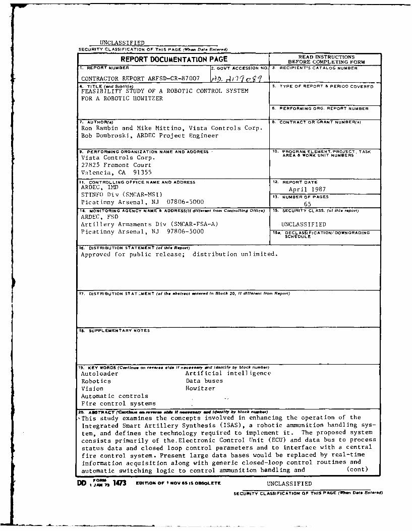
,This study examines the concepts involved in enhancing the operation of the
Integrated Smart Artillery Synthesis (ISAS), a robotic ammunition handling sys-
tem, and defines the technology required to implement it. The proposed system
consists primarily of theElectronic Control Unit (ECU) and data bus to process
status data and closed loop control parameters and to interface with a central
fire control system. Present large data bases would be replaced by real-time
Information acquisition along with generic closed-loop control routines and
automatic switching logic to control ammunition handling and (cont)
FO m 1473 EtITION OF I NOV 65 IS OBSOLETE UNCLASSIFIEDDD ISJR73CLASSIFIe
SECURITY CLASSIFICATION OF THIS PAGE (IWhen Date Entered)

UNCLASS IFIEDSECURITY CLASSIFICATION OF THIS5 PAGE(When Data Entered)
20. Abstract: (cont)
delivery in a rapidly changing environment. The implementation of new sensingmethods, such as vision technology, is also investigated.
UNCLASS IFIEDSECURITY CLASSIFICATION OF THIS PAGE(W7,on Dot* Entered)
TABLE OF CONTENTS
Page
INTRODUCTION............................................1I
Background..............................................1IObjective...............................................1IScope................................................... 1
BASELINE EVALUATION.................................... 2
Present ISAS System.................................... 2Mechanical System................................. 2Control System.................................... 4
General Mechanical System.............................. 4Constraints....................................... 4Sequence of Events................................ 12Proposed Mechanical Systems...................... 14
Control System Concept................................. 20
STRUJCTURAL AND MECHANICAL DESIGN...................... 20
Geometrical Solutions.................................. 23Ammunition Storage................................ 23Transfer Unit..................................... 23
General Enclosure Form Factor......................... 28
SENSORS................................................. 28
Requirements............................................ 28Existing Sensors....................................... 29Additional Sensors............................ 29
Alternate Mechanical System Motion Sensors . 29Improved Dynamic Response........................ 31Verification...................................... 31Redundancy......................................... 31
Final Configuration.................................... 33Position........................................... 33Rate............................................... 33Acceleration...................................... 33Force.............................................. 34Discretes.......................................... 34Vision............................................. 34
STABILITY AND CONTROL REQUIREMENT..................... 34
Servo Loops............................................. 35
Command and Control.................................... 35
REDUNDANCY ......................................... 36
Requirements ....................................... 36Failure Modes and Effects Analysis ..................... 36
AECU DESIGN ........................................ 36
Introduction ....................................... 36Central Processor Card ............................. 37Memory Card ........................................ 37Video I/O Card ..................................... 40Control Loop Processor Card ............................ 40Input/Output Card .................................. 40Processor Selection ................................ 46Analog vs. Digital ................................. 46Packaging .......................................... 46Language Selection ................................. 48Software Structure .................................. 48Executive Processing ............................... 48Control Loop Processing ............................ 48Input/Output Processing ............................ 48Control Laws ....................................... 51
CONCLUSIONS ........................................ 52
RECOMMENDATIONS .................................... 53
References ......................................... 55Bibliography ....................................... 57Distribution List .................................. 59
Accession For
NTIS- GRAJ"DTIC TABUnannounced ]Justliflcatlon-
Distribut ion/____
Availability Codes
Avail and/o-Dist Special
ii
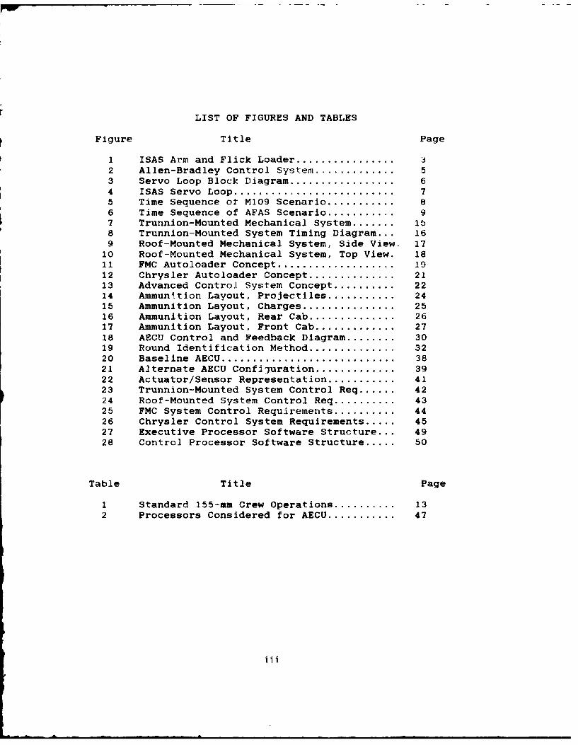
LIST OF FIGURES AND TABLES
Figure Title Page
1 ISAS Arm and Flick Loader ................ 32 Allen-Bradley Control System ................ 53 Servo Loop Block Diagram ................... 64 ISAS Servo Loop ............................ 75 Time Sequence ot M109 Scenario ........... 86 Time Sequence of AFAS Scenario ........... 97 Trunnion-Mounted Mechanical System ....... 158 Trunnion-Mounted System Timing Diagram... 169 Roof-Mounted Mechanical System, Side View. 17
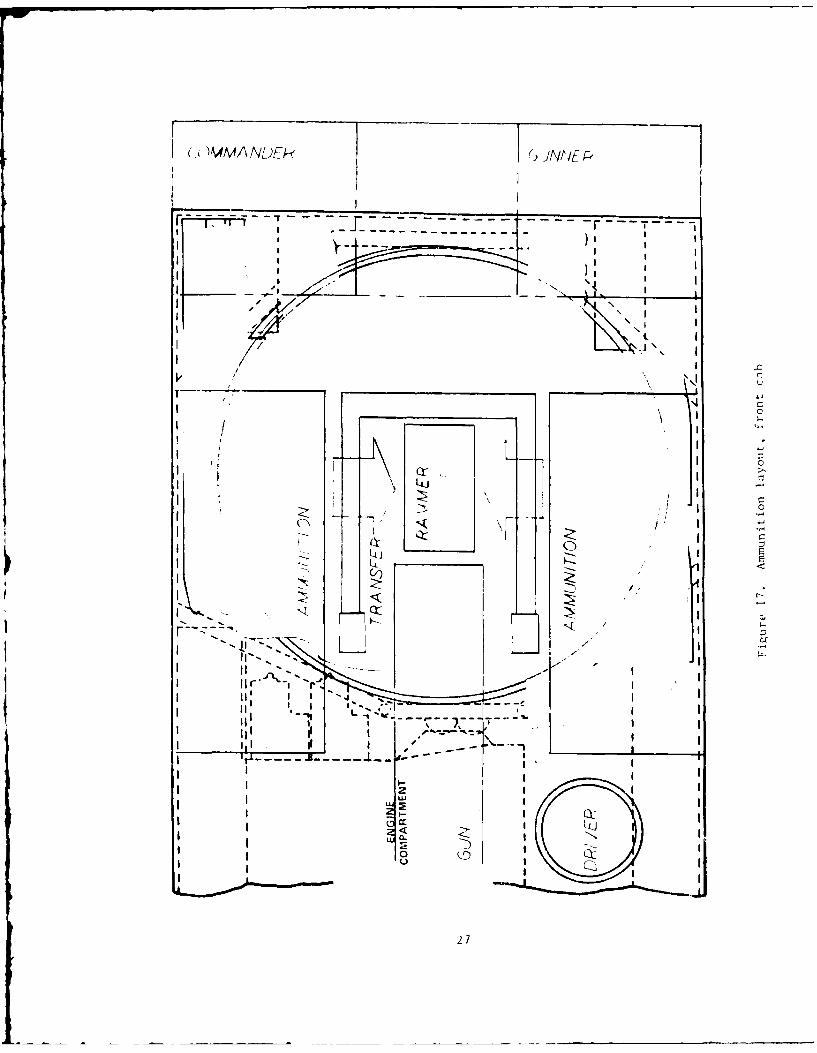
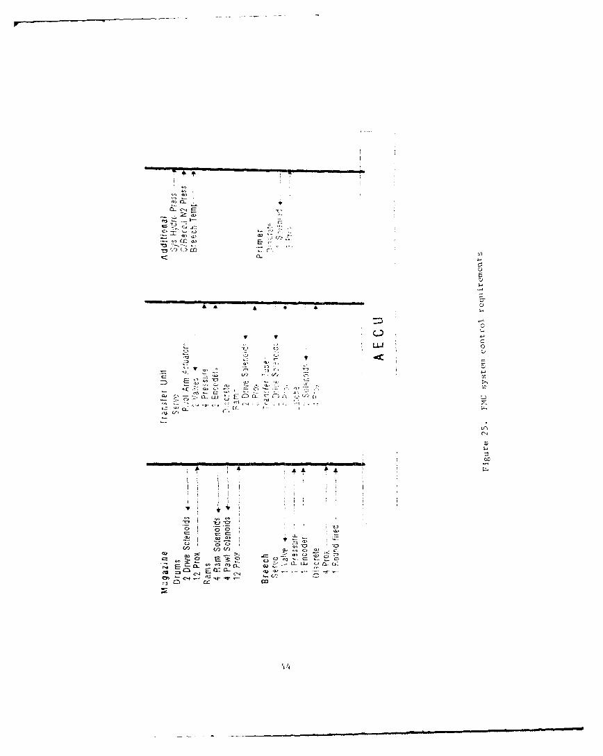
10 Roof-Mounted Mechanical System, Top View. 1811 FMC Autoloader Concept ..................... 1912 Chrysler Autoloader Concept ................ 2113 Advanced Control System Concept .......... 2214 Ammunttion Layout, Projectiles ........... 2415 Ammunition Layout, Charges ................. 2516 Ammunition Layout, Rear Cab ................ 2617 Ammunition Layout, Front Cab ............. 2718 AECU Control and Feedback Diagram ........ 3019 Round Identification Method ................ 3220 Baseline AECU ............................... 3821 Alternate AECU Configuration ............. 3922 Actuator/Sensor Representation ........... 4123 Trunnion-Mounted System Control Req ...... 4224 Roof-Mounted System Control Req .......... 4325 FMC System Control Requirements .......... 4426 Chrysler Control System Requirements ..... 4527 Executive Processor Software Structure... 4928 Control Processor Software Structure ..... 50
Table Title Page
1 Standard 155-mm Crew Operations .......... 132 Processors Considered for AECU ........... 47
iii
INTRODUCTION
Background
In recent years, advances have been made in applying
automation or robot technology to artillery vehicles inorder to improve combat effectiveness. One aspect of this
involves the automated loading and firing of ammunition.The Integrated Smart Artillery Synthesis (ISAS)
vehicle is a testbed that demonstrates these advancedrobotic concepts. It is based on an Mi09AIB 155mm self-
propelled howitzer. Among the concepts that itdemonstrates is a projectile and charge autoloader systembased on a jointed, multiple degree of freedom, turret-mounted robot. Control of this system is presentlyachieved using a standard Allen-Bradley industrialcontroller and various sensors.
In order to further improve the reliability of thisautuloader, an advanced control system investigation wasrequired. This study was performed to apply existing
microprocessor-based electronic control unit (ECU)technology, and to examine innovative solutions to theelectronic control of a robotic autoloader in order todetermine the configuration of an advanced ECU (AECU).Project objectives are discussed in the following section.
Objective
The original objective of this project was to enhancethe operation of the ISAS autoloader robot using anadvanced control system that would incorporate componentredundancy, automatic moding logic and artificialintelligence, and a variety of sensing methods, includingmachine vision.
After the project was awarded, Vista Controls wasinstructed by ARDEC to slightly modify the projectobjectives. It was desired that the study results bedirected to a more generic system. To do this, variousmechanical designs would be evaluated, with estimationsmade of the required new sensor suite, vision system, servoloops and a resulting generic controller.
Scope
This report addresses the requirements and conceptualdesign of an AECU. Several existing ammunition handlingsystems were examined, and significant development was doneon alternate autoloaders. These systems formed thebaseline system and worst case requirements that an AECU
1
would need to control. They also pointed the way to thebest types of sensors and advanced control methodologiesthat could be applied to improve operation.
The AECU itself was then developed, using severalapproaches incorporating different architectures. The AECUconcept that was determined meets the objectives ofapplying advanced control methods with flexibility to beused with many types of machines.
BASELINE EVALUATION
Present ISAS System
The ISAS system was considered the baseline, both froma mechanical and control system point of view (ref. 1).Each of these aspects are discussed in the followingsections.
Mechanical System
The mechanisms associated with the ISAS havebeen evaluated to provide the number and types of controlloops required. The major components of the present ISASare the robotic loader, sliding-block breech and flickloader tray. Extensive detail development of ISASimprovements has been neglected in favor of researchtowards generic control system concepts.
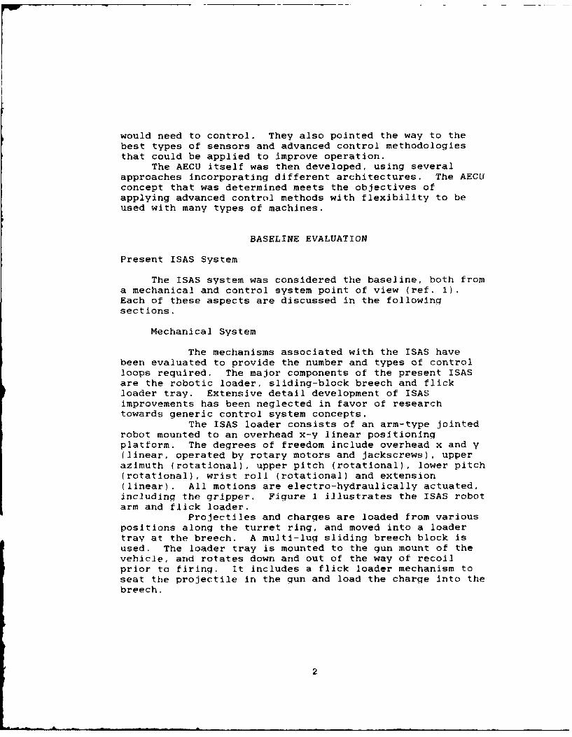
The ISAS loader consists of an arm-type jointedrobot mounted to an overhead x-y linear positioningplatform. The degrees of freedom include overhead x and y(linear, operated by rotary motors and jackscrews), upperazimuth (rotational), upper pitch (rotational), lower pitch(rotational), wrist roll (rotational) and extension(linear). All motions are electro-hydraulically actuated,including the gripper. Figure 1 illustrates the ISAS robotarm and flick loader.
Projectiles and charges are loaded from variouspositions along the turret ring, and moved into a loadertray at the breech. A multi-lug sliding breech block isused. The loader tray is mounted to the gun mount of thevehicle, and rotates down and out of the way of recoilprior to firing. It includes a flick loader mechanism toseat the projectile in the gun and load the charge into thebreech.
2
4NIr I
Figure 1. ISAS arm and flick loader

Control System
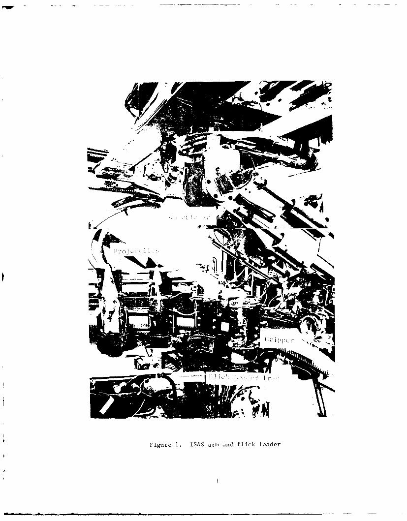
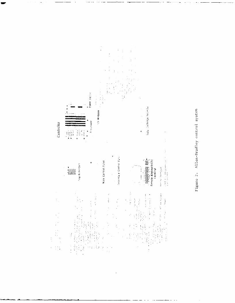
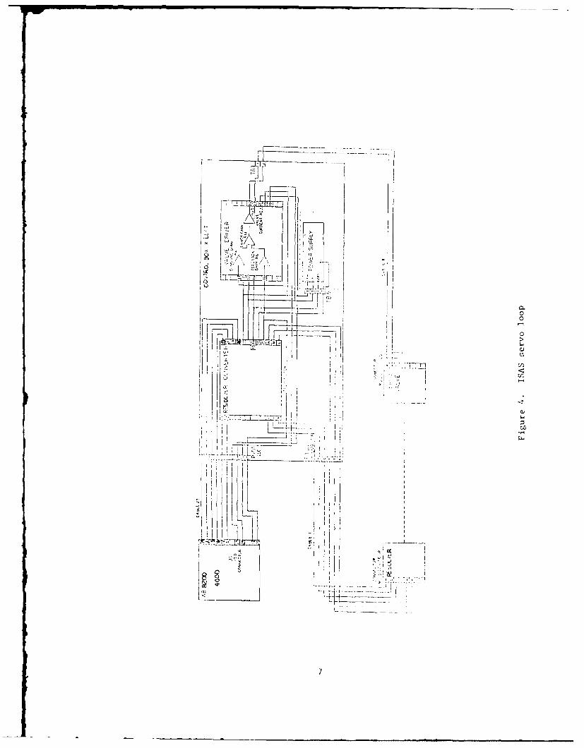
The present control system consists of an Allen-Bradley controller and peripherals (figure 2) commanding aservo control box, which drives the robot hydraulics(figure 3). The servo loops employ resolver feedback, anduse fairly basic compensation, as shown in figure 4. Thereare 5 flick loader proximity switches fed directly to theFCC, and 6 limit switches and 5 proximity switches that areinput direct to the AB controller. As can be seen infigure 2, the AB controller consists of several panels andperipherals, and is primarily configured to industrial typeapplications. This yields a bulkier, more complicatedsystem than is necessary, and is also not constructed forthe shock environment of the M109.
Motion control consists of pre-programmed, point-to-point subroutines in the AB that are called and executedby the fire control computer (FCC).
General Mechanical System
The next step in evaluating a generic control systemwas to estimate other types of mechanical systems to becontrolled. The driving aspects of such devices areexamined in the following sections. Overall constraintsare set forth, including the man-machine interface, turretconstraints, round and charge type and resupply interface.The required sequence of events to perform the autoloadingtasks is then detailed. This determines the requiredcombination of motions, geometry, structures and resultingcontrol system to accomplish the task.
Finally, several mechanical autoloader configurationsare proposed, and compared on their respective merits andfrom a controller point of view. The original ISAS robotis also compared. From this, a controller design isgenerated that will be flexible enough to accommodate thesedifferent mechanical systems.
Constraints
Figures 5 and 6 are timing diagrams for futurebattle scenarios involving field artillery that werepresented in the Vista Controls AFAS Requirements Overviewwhite paper (ref. 3). Figure 5 depicts a typical timesequence of events of the existing M109 during engagementin this battle scenario. Alongside the M109 sequence is anexpected counterfire scenario for future technology. Thetime sequence represents present M109 performance ratherthan that required for an AFAS. This sequence highlights
4
41J
r. r)
1Xa -4
ALI II
z lao.,-
ALIEN -R&rY2O
AXs PET X AXJS RIGmTE AI LEFT
C( X. -ITO- .O
r. CS I -z
___________ =LY2. X" sI ~RESOLVERj OL AI
SIO -LI AXIf
I L L R iTCH I
Figure 3. Servo loop block diagram
6.
I
K ~ ~71 p
2
~' LL~~T2f4V-0
L~i
00
-4 0
Ii 0iiHI.
-~ HiC
V* I 0
Ljto
I ~ I
II
IIIIII I
7

ELAPSED TIME
(SECONDS)
0 SECOND
CREW EXITS VEHICLE LuiVEHICLE DROP SPADES U)PREPARATION BACKUP VEHICLEONTO SPADES 0
cJ
SET-UP COLLIMATOR 20GUN LAYING UNLOCK GUN 0TRIANGULATE WITH
COLLIMATOROPEN BREECH -30SET FUZE
ARMING WITH CHAMBER ROUNDFIRST ROUND LOAD POWDERCLOSE BREECHLOAD PRIMER
TARGET WEAPON ON TARGET 43WEAPON STABILIZEACQUISITION FIRE %. RECOILSWAB CHAMBER - 50SET FUZEARMING WITH CHAMBER ROUND L z
SECOND ROUNDLOAD POWDERCLOSE BREECH LLOAD PRIMER
TARGET WEAPON ON TARGET 65WEAPON STABILIZE --
ACQUISITION FIRE & RECOIL
SWAB CHAMBER 72 7 1SET FUZEARMING WITH CHAMBER ROUNDTHIRD ROUND LOAD POWDER 79CLOSE BREECHLOAD PRIMER
TARGET WEAPON ON TARGET 87 zWEAPON STABILIZE r- RADARFIRE & RECOIL 9394 DETECTION
LOWER GUNLOCK GUNCLOSE BREECH 0202 ACQUIRERELOCATION REPLACE COLLIMATOR 0- TARGETPREPARATION CREW RETURN TO VEHICLE
1UNLOCK SPADES 108FORWARD VEHICLE TO
LOOSEN SPADESCOUNTER-FIRE119 FLIGHT
O~j TIME
1 28 IMPACT
DRIVE 1/2 KM AWAYRELOCATION FROM COUNTERFIRE 0FOOTPRINT CENTER(30 MPH MAX.)
157
1~. I ~ ~ f mi 09 rvnario
ELAPSED TIME(SECONDS)
VEHICLE PREP uNL c SECONDOPEN BREECH - SCN
AUTO ARMING SET FUZEWITH LOAD ROUND -FIRST ROUND LOAD PRIMER -
TARGET WEAPON ON TARGET -- 13 NACQUISITION FIRE & RECOIL 17AUTO ARMING SET FUE1
WITH LOAD ROUND -SECOND ROUNDLOAD PRIMERTARGET WEAPON ON TARGET 29ACQUISITION FIRE & RECOIL O33
AUTO ARMING SET FUZE rWITH LOAD ROUNDTHIRD ROUND LOAD PRIMER --
TARGET WEAPON ON TARGET 4 5ACQUISITION FIRE & RECOIL -- 47LOWER GUN -- 50 -- 49RELOCAT PREPLOCK GUN Z tCLOSE BREECH -- 56 - RADAR
C\j DETECTION
DRIVE 1/2 KM AWAY lJRELOCATION FROM COUNTERFIRE U)FOOTPRINT CENTER(45 MPH MAX.) 0 70 -- 70 ACQUIRE-j-74 TARGET
COUNTER-
FIRECoj FLIGHTCOj TIME
-- 96 IMPACT
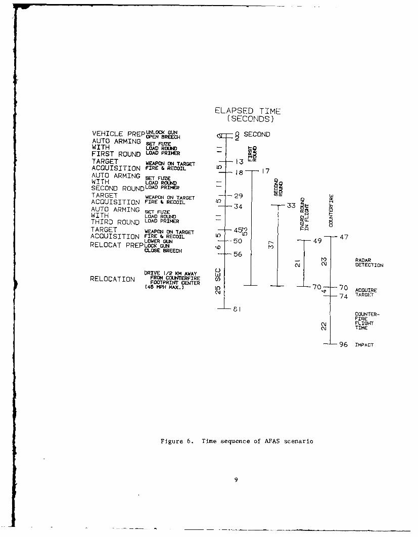
Figure 6. Time sequence of AFAS scenario
9
where major improvements for an artillery system arerequired and where deficiency of current systems are mostapparent.
In the time sequence, during firing of a three-round burst, enemy counterfire impacts at the 128 secondmark, before the self-propelled howitzer has theopportunity to move. The time sequence for a two-roundburst is 22 seconds less than the three-round burst. Thetime saved allows the vehicle to be out of the onekilometer diameter counterfire footprint in 135 seconds,still not quick enough to match the counterfire impact at128 seconds. Therefore, with the present system, the onlysafe alternative is to fire one round and immediatelyrelocate. Time elapsed is now reduced to 113 seconds. Asa result, there is a margin of 15 seconds between leavingthe one kilometer diameter counterfire footprint and thetime of counterfire impact.
The present artillery system may increasesurvivability by limiting firing to a one-round burstbefore moving. The increased survivability comes at asacrifice in lethality due to an overall firing rate ofonly one shot per 115 seconds, an average of .5 shots perminute (spm). The time sequence may be separated intothree major portions:
1) responsiveness, covering vehiclepreparation and gun laying,
2) firing rate, which includes arming of thegun and target acquisition, and
3) mobility, covering relocation preparationand the actual relocation.
Of the three, mobility is the driving factor forincreased survivability, while elapsed time reductions inthe combination of all three increases lethality by raisingthe overall firing rate.
Fignre 6 depicts a time sequence of an AFAS withall the improvements as suggested in the followingsections. As compared to the original time sequence forthe existing MIO9, the 50 seconds required for vehiclepreparation and gun laying are totally eliminated. Armingof the first round is at 11 seconds rather than 13seconds. Tarqet acquisition time is at five seconds perround, shortened by two seconds as compared to the originalsystem. Arming and loading of each successive round isreduced to 11 seconds from the original 15 seconds.Relocation preparation is shortened by 19 seconds to afinal time requirement of six seconds. This scenario showsthe AFAS ran fire a three-round burst and exit the counterfire footprint in 81 seconds and still have 15 seconds ofmarqln from counterfire attack.
10

The overall firing rate tor the AFAS is at 2.2
spm; this rate is 4.5 times the overall firing rate of theexisting Ml09 in a future battle scenario. Theincorporation of the subsystems will also decrease crewsize. Since the requirement for a loader, a crew member tomonitor the collimator, and a crew member to dispose of theunused powder has been eliminated by the subsystems, atotal minimum crew size of three is required, consisting ofa commander, driver, and gunner.
The following constraints have been chosen asrepresentative of the requirements and challengesassociated with the Howitzer Improvement Program (HIP) andthe Advanced Field Artillery System (AFAS) (refs. 2 and3). The individual merits can be argued, however the mainobjective is to establish the controller interface,computation and throughput requirements.
Three-Man Crew - A three-man crew would consistof a commander, gunner and driver. This allows for two menin the turret to be able to manually load the Copperhead
missile, although failure rates for the autoloader systemshould be low enough that general manual operations are notrequired. A three-man crew capability was alsodemonstrated by the Human Engineering Labs (HEL) testbed.
Load On Move - Loading on the move is not arequirement, since analysis has shown that it does notcontribute significantly to improved firing rates, andwould compromise system safety or cost.
Shoot On Move - Shooting on the move does notappear to be easily achievable in the near future, and isnot a requirement. Analysis shows that shooting rapidlyand then moving is enough to avoid enemy counterfire atthis time.
HIP Configured Chassis - Any autoloading systemmust be adaptable to the chassis and turret systems testedin the HIP. Minor modifications to turret may berequired. This will allow the integration of an autoloadersystem into the overall advanced 155mm self-propelledvehicle (SPV) with a minimum of conflict.
Standard Rotary Breech - A standard interrupted-thread rotary breech block has been assumed, since allplanned HIP configurations are presently slated to usethis. A servo system may be used to replace the standardmechanical release. If a sliding multilug breech is used,the impacts to the control system would be minimal, and
11
involve only modifications to the input/output (I/O)sections of the controller.
Auto Primer Mechanism - This mechanism would bemore or less autonomous. Controller functions wouldconsist mainly of monitoring the amount of primers.
UnLcharg_ - Propellant is assumed to beunicharge. Other types of propellant would significantlyaffect the mechanical system, and thus the number ofchannels and signals to monitor and control.
Positive Ram - A positive projectile rammer,such as a strongback chain is assumed.
Manual Backup - Manual backup modes will beprovided for. System redundancy will be such that thesemodes will rarely be encountered, and will function atdegraded rates of fire.
Magazine - A magazine-based projectile andcharge storage system is envisioned. The overallautoloading task is much simplified if this is done.
Automatic_Fuzin_ Sstem - It is assumed that ageneric controller will need to handle this system. Theonly other alternative is to pre-fuze the projectilesbefore the autoloader gets to them, either in the resupplyvehicle or manually in the 155mm SPV.
Sequence of Events
The individual sequence of events associatedwith riring were obtained from reference 4, and areoutlined in table 1. There are 6 men involved in thefiring process - the chief of section, cannoneers 1 through4, and the driver. The #1 cannoneer performs the actualloading of rounds into the gun. Cannoneers 2-4 and thedriver fuze projectiles, prepare charges and transportthese to the #1 cannoneer. The chief of section inspectsall components of the round prior to loading into the gun.
From these actions, the motions and functionsrequired for the mechanical robot and control system toperform during firing are determined. The capability toselect and fuze projectiles, and select powder is needed,either by a magazine-based bustle system to move the roundcomponents to central locations, or by robotic arms toaccess the components, or by a combination of thesemethods. The use of unicharge simplifies the powderpreparation greatly.
12

Table 1 : Standard 155nn Crew Operaticns
Chief Gjnner I iCaw e r 82 CA vwoeer 33 Cannoeer IV Cannoneer I Driver
I I Inspects, I II Sets Barrel l cleans I Peparesr Helps #4I I I I projectile I propellantI r I Ii
--- 4-... ---------- -- +
I Fuzes projec- I Holds proj- III tile, sets ectile up- I TI I fuze, verifiesl right I
' I I I---- ------- --~ -1 --- -----------------------------
Chcks all I Puts projec- 1 Carries fuzedlcompcrets of J tile Into projectile I'cond Drior I tray, raffs It!: to Ua Ito load-nq into breech,
stores ram i
,I CarriesLoads Charge I Gets rid of I propell ant
i into breech I extra powderj to 31
I I
Closes breech II Inserts prilerlCloes primrer I R E P E A I S 0 P E R A T I N S A S N E C E S S A R Yblock
Attacheslanyard
tires round
Seabs and In-soects chi-
Sbe
1'3
The actual loading is performed by either adedicated mechanism or a jointed-type robot. Subsystems tooperate the breech, load and eject the primers, and firethe gun are required. A vision system will perform theinspection and verification tasks.
Proposed Mechanical Systems
In addition to the ISAS robot, there are severaltypes of mechanical systems that would perform the requiredtasks. Each method that we examined of course involvedcompromises in one form or another. The purpose of thissection is not to come up with the best mechanical systemand do detailed development of it, but rather to put forththe various configurations and evaluate the types orcontrol that each would need. In this way, a genericcontrol system could be designed to be adaptable towhatever system is used in future experiments, and in theHIP.
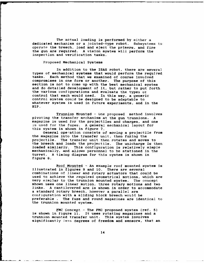
Trunnion Mounted - One proposed method involvespivoting the transfer mechanism at the gun trunnions. Amagazine is used for the projectiles and charges, and oneis used for the fuzes. A general mechanical layout forthis system is shown in figure 7.
General operation consists of moving a projectile fromthe magazine into the transfer unit, then fuzing theprojectile. The transfer unit then rotates and moves tothe breech and loads the projectile. The unicharge is thenloaded similarly. This configuration is relatively simplemechanically, and allows personnel to be stationed in theturret. A timing diagram for this system is shown infigure 8.
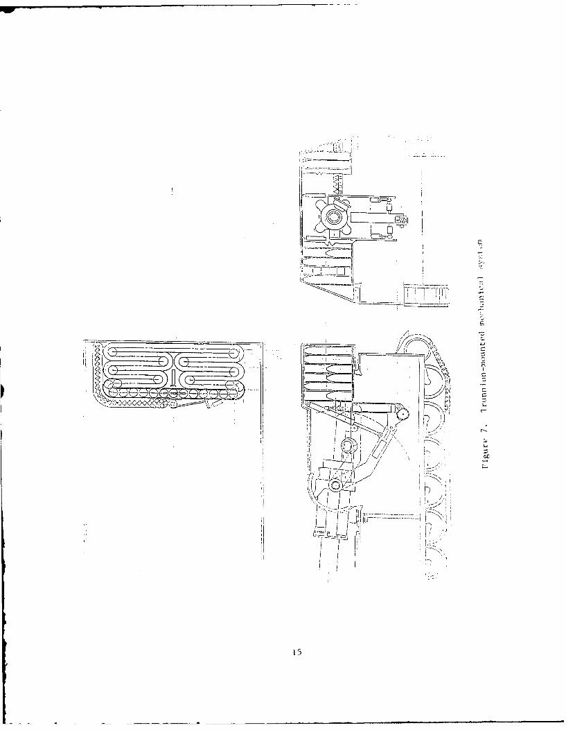
Roof Mounted - An example roof mounted system isillustrated in figures 9 and 10. There are severalcombinations of linear and rotary actuators that could beused to achieve the required geometrical motions, which arevery similar to the trunnion mounted system. The conceptshown uses one linear motion, three rotary motions and twolinks. A cantilevered arm is shown in order to accommodatea standard rotary breech, however a parallel armconfiquration with a sliding block breech would bepreferable . The fuze and round magazines are identical tothe trunnion mounted system.
FMC Concept - The FMC proposed system (ref. 5)is shown in figure 11. It uses rotating magazines and atrunnion mounted transfer unit. This system involvessignificantly Jess degrees of freedom and sensors, that an
14
It_
~ccKi
'ZV711111L1iLi~J~~ ________
_______ EC-
C
\~J). :/~
(~ /7C)0--- H
15

E -~
~A a' -C'
a' {S xi, ~, ,~
a a
' E'-~ o a'
C - C,o c,, ~ .a a' a' E -
~ ~ a C".0 ~ a' 2 a, a~ a' -o ~ a' a a~ a'2:' = -
a a. a - ~ 0 a'_ -= Qa a a 2 .io a'oa'~E0-.. a' a a a
-- ~ Eo ~ a, a
- ~ a'.0aa'~.. ~.0 ~C0
-caa' a a a' a, 0 OJ C C) CC.a'a"'a, oa'o~~s C'a~a' a 0 a' a' a'
~a'a'*~,a' o-±z- a' c~ a _ --. a ~ a' a'a, a'~ a, ~ a ,,. _ '-.0
~~Ca,0OaO 0 ~, - a'a~ ~
a, ~, ~, a'
2
2cJ44
C.)
C
C4, Ci'
0 Ia' --- '--I,---. C
o 0) -, )I, I
,.- I CC
C
* I F-
* ~") I" ,jI,
a' C
C
11 I
16
LL
6
~
2.
-r -
~kxL~LILVLLVE
KJ~~*7i L~ _
K) _
I- 7 - Qz -~
E
.1*- 0 ~ U
/-
-- 4U(
I I
-u
'V __ -~
07' 0
K 0)I
I->
I
1,
'U
17

- I.
_ -J
ii
Iv,~r.
I E
E

Rotatting Drums Transfer Tube
F igure I1I. IM, iutoloader concept

ow
AECU would have to accommodate, than the roof or trunnionmounted systems.
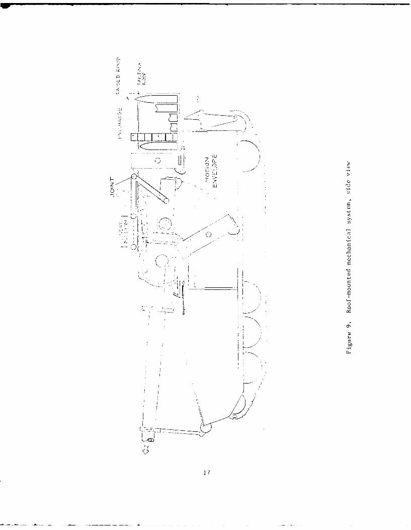
Crysleh pConcpt - This system is illustrated infigure 12, and uses a full rotating breech with asimplified transfer unit (ref. 6). Again, there are nolarge differences in the number or types of controlchannels involved. The control system concept is discussedin the following sections.
Control System Concept
Based on the ISAS, the conceptual autoloaders, andthose proposed by FMC and Chrysler, a control system andAECU configuration is set forth. The AECU itself willinclude expandable slots to incorporate additionalinput/output (I/O) cards, an improved microprocessor, andsimplified and ruggedized packaging. User interface willbe done via a cathode ray tube (CRT) terminal. Otherinterfaces will include the vision system, servo driver boxand fire control computer (FCC) or gunner's station. Thisconceptual layout is shown in figure 13.
The control loops themselves will be accomplished withmultiple digital processors, rather than individual analogservo cards. This is the best method to increaseadaptability to various mechanical systems and toincorporate advanced modern control methods. Details ofthe various aspects of this concept are discussed in theSerects, Stability and Control, and AECU Sections.
STRUCTURAL AND MECHANICAL DESIGN
The intent of this part of the study was originally todevelop the details of the AECU packaging, and to domounting structure analysis for the control components.Since both the ISAS robot and M109 test bed are expected tochange significantly, it was decided to direct more of thiseffort toward development of overall baseline mechanicalautoloading systems. This would allow an AECU to bedesigned that could accommodate what we believe would be anoptimum autoloader. as well as other candidate systems.This further establishes the limits (computational power,I/O, etc.) that a generic AECU should be capable ofhandling.
20
Figure 12. Chrysler autoloader concept
21
CC9
44J
4u
oo C
Li
to co
0-
oco
'TV
F--J
0 -
2:0
zl M
22

Geometrical Solutions
The first step taken in estimating mechanicalconfigurations was to review the required motions of theprojectiles and charges from storage to the breech. Astandard M109 gun was assumed (vs. the re-mounted ISAS guntube), which fixes the breech location within a certainrange with respect to the turret. The storage options werethen evaluated, along with transfer unit geometries andmechanizations.
Ammunition Storage
Figures 14 through 17 illustrate someconfigurations that were reviewed. The ISAS configurationwas developed to a point where projectiles and charges werestored around the perimeter of the turret, both verticallyand horizontally (figure 1). Another configuration,presented at the Artillery Industry Day (Reference 2), usedchassis projectile storage and a full-width turret bustlefor charges and some projectiles (figures 14 and 15). Bothof these concepts would require a flexible, multi-jointedrobotic arm to perform autoloading, and would precludepersonnel in the turret.
Turret-based projectile and charqe storagemethods include FMC and Chrysler concepts (figures 11 and12) and alternate conceptual locations for magazines(figures 16 and 17). Any candidate system should allowvertical storage of the white phosphorous projectiles andmanual loading of the M712 Copperhead. While affected byeach particular implementation, the turret--based systemsare generally more amenable to dedicated mechanical loadersas opposed to flexible robotic arms, and allow personnel inthe turret.
For purposes of this study, we assumed verticalstorage of projectiles and charges in a chain-ladder typemagazine bustle located at the rear of the turret, as shownin figure 5. This addresses the white phosphorous andcopperhead requirements, and the transfer unit would allowtwo operators in the turret during firing.
Transfer Unit
There are several mechanical configurations thatcan achieve the geometrical motion requirements. For theassumed magazine and breech configuration, both thetrunnion and roof mounted systems have the required motionrange. This range of motions needed of the transfer unit,along with the two configurations that we examined andoutlined, are shown in figures 7, 9 and 10. Although themotions for each system could be produced by various
23
~< I
I0 I< LLJJ
I (ncr I -J II 0
< LL>I
224
t - m -
2:w M
u G
L2 U
C)) (1
C'0 '0 0 C)
x- cc x
2C9
I j-~7:
LXI
C')L4
1, rIi
/ I Li
/-- L Vr1
I, , it]
u01IL
- -1
N L) E
4. I0
k \ U
combinations of linear and rotary actuators, the totalnumber of channels for the transfer unit does not exceed 8,with 1 more for the rammer.
The transfer units associated with the FMC andChrysler systems (figures 11 and 12) involve differentgeometrical motions due to the differences in magazine andbreech design. These systems are more limited than thosewe proposed, and involve less servo channels for control.The FMC system requires only 4 channels for the transferunit, with an additional 5 associated with the drums andramming operations. The Chrysler system needs about 4channels for the transfer unit, with an additional 6 forthe breech, rammers and magazine.
General Enclosure Form Factor
The investigation of various tanks and mobileartillery, including the MI-Ei and M-109, indicated thatthere is no standard form factor for the enclosure andpackaging of the electronics being used at this time.Since increased vehicle electronics (vetronics), includingthe proposed controller, communication equipment, etc., arebeing incorporated into modern tanks and field artillery,some sort of standard vetronics bay is required. Such abay would be similar to the avionics bays in modernaircraft.
The recommended choice for this vetronics bay is theAirinc ATR short form factor. This is a standardized baythat can accommodate advanced electronics on standard cardshapes, as those proposed for the Army LHX family ofhelicopters, resulting in commonality of components andlogistical benefits. This packaging method also allows forfuture electronics expansion.
SENSORS
The purpose of this section is to evaluate the typesof sensors that may be implemented to control a givenautoloading system. The existing ISAS sensors areconsidered the baseline. These establish a set of minimumrequirements for the controller I/0 and servo loops.Different types of sensors that could be applied to ISAS,or any other mechanical system, are also examined.
Requirements
sensor types fall under two general categories: motionor servo control and verification. Motion control sensorsare required in the feedback loops that control the robot
28
motions, as well as the magazine and other subsystemmotions. Verification sensors are implemented to providethe inputs that will allow the microprocessor toessentially duplicate the human operator decision-makinaprocess. Functions will include projectile, fuze andcharge identification and selection, system statusdetermination, and safety observations. These subjects aredetailed in the following sections.
Existing Sensors
A diagram showing the existing ISAS sensors is shownin figure 3. The transfer robot uses 6 angular encodersand I linear encoder. There are 6 limit switchesassociated with the x-y gantry mechanism. The flick loaderincorporates 5 proximity switches, whose signals are feddirectly to the FCC. There is a shot sensor proximityswitch mounted in the gun. The breech block uses 4proximity switches tied to the breech controller and FCC.
All the servo loops are single redundant. Theexisting system does not incorporate the subsystems, suchas the magazine bustle, fuze mechanism and auto primersystem, that are included for the estimation of requiredadditional sensors.
Additional Sensors
The existing ISAS set ot sensors probably representsthe minimum that a generic controller would need toaccommodate. Additional numbers and types of sensors arerequired for redundancy, improved dynamic response, andmechanical systems with more control loops. The maximumestimated number and types of sensors will be addressed inorder to design an AECU of sufficient capacity. Theseissues are discussed below.
Alternate Mechanical System Motion Sensors
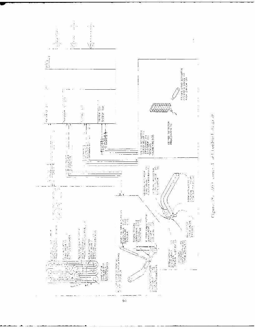
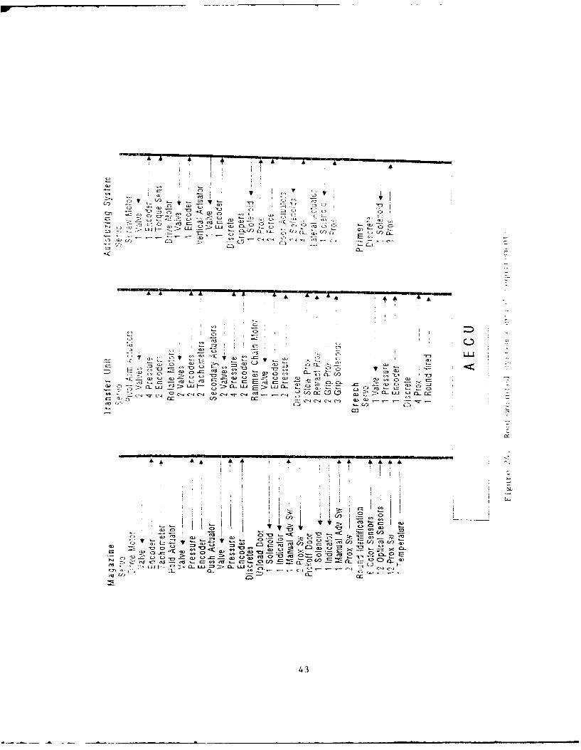
The basic motion sensing requirements of analternate mechanical system are similar to the ISAS,differing primarily in the number of degrees of freedomthat require control. The control loops evaluated hereinclude those in the transfer unit, loading mechanism,magazine, auto fuze mechanism, and auto primer, since ageneric AECU will have to accommodate these systems. Theexpected worst case with respect to I/O and servo channelcapacity is for a system similar to the roof or trunnion-mounted system. A control and feedback diagram for thissystem is shown in figure 18.
29
__________ I CF
'2W N
/I 2
/
V//i
N I N
~TV ~Tfl . i
Cii C,
A
.i~FU / /
N
CLI ~ 'IC.
7C' N.C~
y , /2
a IC~C~t
' -
vi
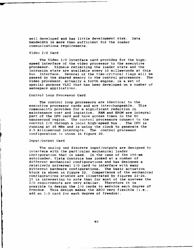
The transter unit itself will use 25 feedbacks
for the servo loops. These include pressure transducers,encoders, tachometers and force sensors. The magazine will
have 3 servo channels using 9 feedbacks. The autofuzingmechanism will require 3 servo channels with 7 feedbacks,while the breech may require I servo channel with 2feedbacks.
The capacity for handling several channels offorce sensing must be provided for. These sensors will beused to measure grip forces associated with ammunitionhandling, and seating forces of projectile ramming. Thiswill not pose a problem, since the digital control loopswill be easily programmable to deal with force feedback, aswill the command software and logic.
Improved Dynamic Response
Higher bandwidth in a servo system results infaster, more precise response, with less overshoot andoscillations. Servo systems with certain mechanicalconfigurations can be improved dynamically by severalmethods. One is to use higher derivative sensors in theloop closures for increased gain and higher crossoverfrequency. These include rate sensors and accelerometersmounted on mechanical members, and delta pressuretransducers installed in hydraulic actuators.
Verification
Verification involves using sensors to check thesystem for correct, safe operations. A standard sensorused for this is the proximity sensor. In the complexoperation of loading and firing rounds, many mechanicalfunctions must be done in harmony for the system to
function. Proximity switches will be the primary method toensure that commanded motions have been completed.
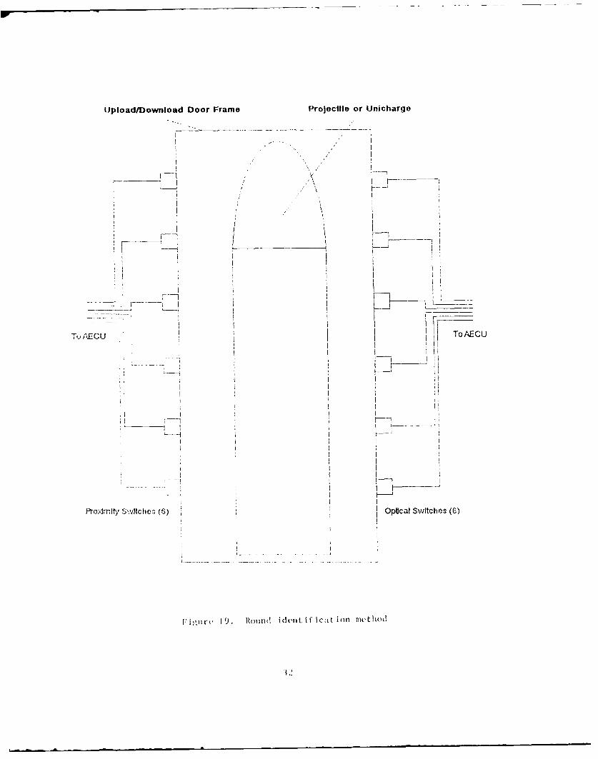
Optical color sensors and prox. switches will beused to detect round presence and type during loading andunloading from the magazine. An example system, shown infigure 19, uses prox. switches to detect round height andoptical sensors to detect color bands. Unichargecartridges can be detected by the color sensors. This willallow the AECU to keep track of projectiles and charges,which is necessary for automatic operations.
Redundancy
System redundancy can be accomplished in severalways. The basic method is to duplicate all failure-pronemechanisms and sensors. Simple duplication would require
31
Upload/Download Door Frame Projectile or Unichargo
_____ C KoA-
PI;Jrt SvlceI 6 pclS~ce 6
i.7L 2 ) Rudietficto ito
doubling such items as the prox switches and opticaldetectors.
An alternative redundancy scheme is to use avision system to determine the system state. This has theadded advantage of dissimilar redundancy, or cneckinq thesame parameters by different methods.
Final Configuration
The final sensor suite will not be detailed to greatlengths, since any particular mechanism will have difterentsensor requirements. However, certain areas of sensorusage have been identified as common to most autoloadingsystems. Also, the proposed controller card designs aresuch that any combination of the recommended sensors can beimplemented as necessary. The sensor types are outlined inthe following sections.
Position
Resolvers and encoders are standard devices usedfor mechanical joints and the magazine. These feedbacksianals can be fed through a derivative computation tosimulate a rate feedback. Position feedback from anultrasonic ranger may be desirable for certain specificapplications, and can be accommodated by the AECU.
Rate
Tachometers are expected to be used for itemssuch as the rammer, magazine, an"' autofuzer to providedirect rate feedback. These are mostly used for speedcontrol applications.
Acceleration
Higher derivative acceleration terms can bemeasured using small accelerometers attached to key partsof the mechanical structure. They are most useful whentrying to achieve high-rate, high-bandwidth systemresponse, which is an expected characteristic of anadvanced autoloader. They can also be used to compensatefor undesirable structural dynamics and resonances.
Also providing acceleration feedback will bepressure transducers on the electrohydraulic actuators.This provides a dynamic feedback equivalent toacceleration, and can be further used as a steady-stateforce control feedback parameter. This is necessary forgood static robot performance in an acceleration (i.e.gravity) field, when carrying heavy loads, and in the
33

robotic mating or contact of different hydraulic actuator
components with stationary surfaces.
Force
Force sensors, such as load cells and straingauge devices, are expected to be used in controllingprojectile seating forces and grips, in addition to thoseaspects described in the previous paragraph.
Discretes
Proximity switches have been demonstrated to bethe most reliable devices, as compared to mechanical limitswitches, in providing presence/absence information onmechanical components. These are used extensively in thepresent ISAS and MI-El TTB autoloader, and are relativelyinexpensive.
Vision
A Vision system interface capability isrecommended for the AECU. At this time, it will beprimarily used in providing redundancy for the positionfeedbacks, and in safety management.
The position redundancy consists of primarilythe discrete proximity switches, and in some cases theencoder/resolver position signals. Algorithms to detectpresence/absence by vision are very easy to implement.These algorithms are also applied to detecting humanpresence within the operating envelope of the autoloader.More complex position computations are possible given anappropriate vision system and algorithms.
Camera systems such as the Fairchild CCD/CAM5000 are extremely small, rugged and versatile, and can beconfigured so that multiple cameras cam be located, andeach used by 1 processor during different phases of theautoloader sequence.
STABILITY AND CONTROL REQUIREMENT
A generic AECU will have to accommodate commandstructures, servo control loops and discrete control loopsfor a variety of mechanical systems. The autoloadersystems that we examined range from mechanized automation(Chrysler, FMC) that involve a minimum of servo control andprogrammability to a highly flexible robotic system (ISAS)requiring significant servo loops and computation for pathcontrol. The factors influencing the stability and control
34
41 aspects of the AECU are discussed in the following
sections.
Servo Loops
Three of the foundation issues involved in servocontrol design are the physical system to be controlled,the desired control parameters or states and their
responses, and the available sensed parameters or states.For this specific AECU, the physical systems are notknown. We will assume the transfer unit to be somehydraulically-based mechanism, with the associatedsubsystems (magazine, autofuze) also hydraulic.
The main desired control states are the position ofthe transfer unit, magazine, fuzer and breech. Also to becontrolled are various forces associated with safe general
hydraulic operation, fuzing, projectile seating and gripforce. The available feedback sensors are discussed in theSensors Section.
The use of digital, microprocessor-based control loopswill allow the application of many modern controlstechniques, including state space, multi-input, multi-output, and optimal methods.
The servo loops will have sufficient speed to obtaincontrol bandwidths to 100 hz. This implies digital timingof at least 500 hz.
Command and Control
The command and control functions are programmed intothe AECU firmware. This will consist of programs toperform the required autoloading tasks. The main routineswill use logic and subroutines to drive the servo loopswith the correct timing, rates and displacements. Thismethodology allows iterative user development through a PC-type terminal.
The software will be designed to allow the use ofadvanced control techniques in the command loops. Standardsingle-axis command structures will be replaced by matrixoperations that will optimize the path control andfavorably impact stability, as judged by the cross-coupling, speed and overshoot criteria.
35
REDUNDANCY
Requirements
Based on the initial overall system assumptions, theredundancy requirements for an autoloader were evaluated.The first failure level involves sensor failure. Failuresof this nature can be compensated for by using multiplesensors to measure the same parameter, and by using avision system to provide dissimilar redundancy. The AECUexecutive processor will provide the redundancy managementlogic and weighting, coordinating measured sensor valueswith reasonable values and with the vision system.
The second level involves individual mechanicalcomponent failures, such as electro-hydraulic servovalves.A correctly designed autoloader using multiple actuatorsand motors for the transfer units, magazine, rammer andautofuzer can compensate for this. A single failure can bedetected directly or empirically by the AECU, with commandchanges to the remaining functional component compensatingat reduced overall rates.
In the case of total electrical or hydraulic failure,a manual backup capability is required. This takes theform of hand cranks on items such as the transfer unit,magazine, rammer and breech. Also appropriate will bemoving the transfer unit out of the way, such as againstthe roof or floor, to permit manual loading. A fullyrobotic howitzer could not of course tolerate such afailure, and would need redundant electrical and hydraulicsubsystems. Unlike the previous two failure modes, thistype of failure cannot be dealt with in the AECU or controlsystem, and is solely a function of correct mechanicaldesign.
Failure Modes and Effects Analysis
A detailed FMEA was not performed due to the lack of aspecifically delined autoloader or robot, such as the ISASor second generation FMC device.
AECU DESIGN
Introduction
The design of an Advanced Electronic Control Unit(AECU) required the investigation of several new processorsand high level languages. Further, a study was made of thebest architecture for the dedicated control task of a 155-mm autoloader. Some of the conclusions came from the work
36

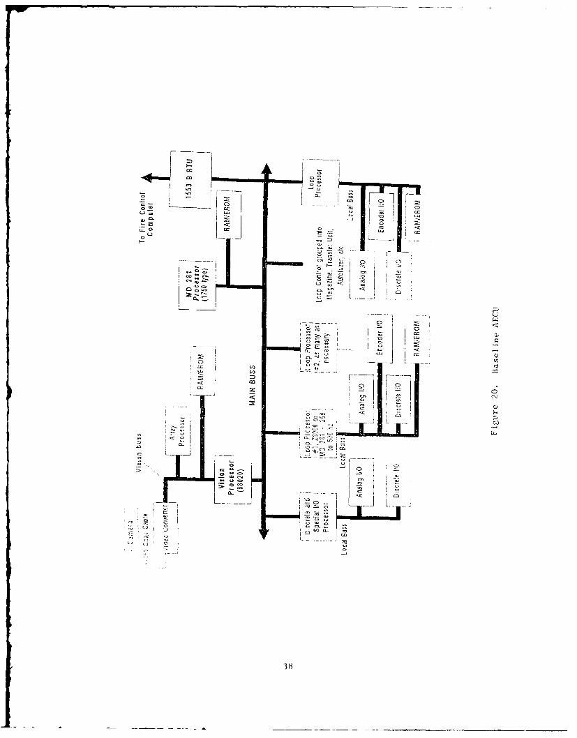
done by Vista Controls on the MI Tank autoloader system inwhich a multi-processor system was used to control themagazine and the transfer unit. Analog position and torceloops were used to provide position control and loadlimiting. This configuration works well but is somewhatrestricted with respect to changing gains dynamically andperforming kinematic calculations in real time. Themultiple processor architecture shown in figure 20represents our current approach to the autoloader controlsystem. There are several ways of interfacing the variousprocessors with the main control processor. One is memorymapping using DMA, the other is using the standardinput/output calls. For reasons of speed, the DMA memorymapped method is chosen for this application. The hardwarearchitecture for the AECU that we recommend is shown infigure 20. Although shown as a bus -structured, multi-processor system, we are actually using a shared memorytechnique which allows the control loop processors tocommunicate with the executive processor through a DMApath.
An alternate hardware architecture is shown in figure21, and uses an analog control loop closure. The reasonsfor the all-digital approach are discussed in the Analogvs. Digital section.
Central Processor Card
A MIL STD 1750 processor was chosen for the executiveCPU because of the directive to standardize on the 1750 forfuture military weapon systems, and because this processoris being used in a number of curient aerospace applicationswith good success. Vista Controls has found the supportfor the 1750 devices growing daily. The speeds of thedevices are also increasing rapidly, as significant R&D isbeing applied to their development. The MD-281 and the F-1750 appear to the best candidates for this application.They can easily meet the throughput requirements andsupport the frame-driven structure needed by theautoloading system.
Memory Card
Memory for the executive processor shares two roles;one as program memory for the executive processor and oneas shared memory for I/O communication with the controlprocessors.
A 1553B communication I/O attached to the main orexecutive bus will be used to communicate with the firecontrol computer to receive commands and send status of theloader system to the fire control computer. This card is
37
71i
cc a)
-2~~ E '
0-co
12 Z

H-cc
r CI Cl
I" ~
a- --~ I 0.) --
-~IL.O
(.1 Ct -o - - ()
Ceo*' 0. Cl ..- I- J~J(N C
~ *~, a- *E
I ~
LIII)- ~
(-3
Ct 0 4
0- cc c~-~ '- Li
I - -
-zccc -~ .- C.)
CN-4
4) 00 I
.0 -
E A 0
4) (~ .~
39
well developed and has little development risk. Databandwidth is more than sufficient for the loadercommunications requirements.
Video I/O Card
The Video I/O interface card provides for the high-speed interface of the video processor to the executiveprocessor. Signals reflecting the loader state and the
intrusion state are available every 10 millseconds at thisbus interface. Several of the time-critical flags will bepassed by the shared memory to the control processors. Thevideo processor, actually a forth engine, is a set ofspecial purpose VLSI that has been developed on a number ofaerospace applications.
Control Loop Processor Card
The control loop processors are identical to theexecutive processor cards and are interchangeable. Thiscommonality provides for a significant reduction inmaintenance cost and logistics. RAM and EROM are integralpart of the CPU card and have access times in the 60nanosecond region. The control processors connect to thecontrol I/O through a local high-speed bus . The CPU isrunning at 25 MHz and is using the clock to generate the2.5 millisecond interrupts. The control processorconfiguration is shown in figure 20.
Input/Output Card
The analog and discrete input/outputs are designed tointerface with the particular mechanical loadercontiguration that is used. In the case of the 155-mmautoloader, Vista Controls has looked at a number ofdifferent mechanical configurations and has designed a
relatively universal I/O card to interface with manydifferent hardware configurations. The basic actuationblock is shown in figure 22. Comparisons of the mechanicalconfigurations studied are illustrated by figures 23-26.
It is interesting to note that for most of the systems theI/O requirements are very similar. Therefore it ispossible to design the I/O cards to service each degree offreedom. This design makes the AECU very flexible (i.e.,add an I/O card for each degree of freedom).
40

Discrete Inputs Actuation ModuleElectro - hydraulic, linear or rotaryTorque Motor
Drive Signal Stepper MotorH-igh speed Motor, Gear Train
Position Feedback I Each degree of freedomSensor or joint 13 represeriterI
by ono actuationRate Feedback 4Module 1 module
Acceleration Feedback .4
Force Feedback 4
Pressure Feedback
Proximity Discrete
Othor Discrete Outputs
Figure 22. Actuator/sensor representation
41

CD C)_ LC C
CDC C ,
CL.
30 L ::3 ZCC U I
4..C) C..-C CC. ()C0 0 < *~C 42
C, 12, 1z
rLL T5'sz' ~(I) 'Uf) (f)
cmAL-fi
iA 44 44 44 4444 44 4
0Z
CO , -Oa -j ( -
c-,'
c x
cc_> C. C2v C) C a>
43
CA
- a3
cc
C' CILL~
cu- C-, 9'" -C-,
"D C:7
ViN
coo
4 4

-I:>
C)
C.C)
LU
C= z
LC
C>C
= --
.) - 014c
45
Processor selection
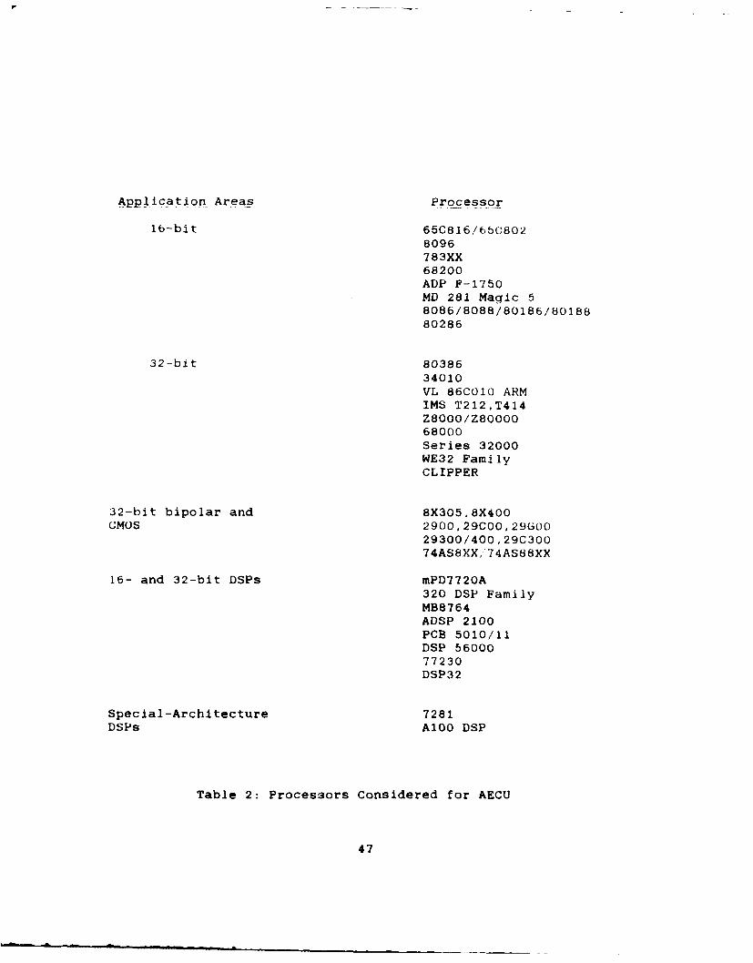
A number of processors were considered for the loadertask, as shown in table 2. Vista Controls recentlyperformed the same trade study for the AH-64A helicopterfor McDonnell Douglas Helicopter Co. The basic conclusionsare that most of the commercial processors are notmaintained long enough to support a military program, andthat most are not sufficiently radiation hardened tosurvive a mild level of radiation. The 1750 series ofprocessors has a clear edge in this review. There areseveral situations that the 1750 series does not handlewell: in particular, bit manipulation is relatively poor intime efficiency. The DOD mandate of using 1750 in newdesign is also a good reason for choosing this processor.Because of the mandate, a significant amount of supportsoftware is becoming available to the developer. Thecomplier efficiencies are also becoming much better, andare producing very compact code. Although ADA-basedcompliers have not shown good efficiency in control lawcode in the past, our recent use of these has shown afactor of three improvement. Projections indicate that ADA1750 object code should be equal to C code within the year.
Analog versus Digital
The trade between a analog inner control loop and adigital control loop has been the subject of many studies.Our experience has shown that the hardware is now availableto do digital loop closure. With the high speed I/O,control loop rates of 500 updates/sec are achievable. Thisallows structural notch filters to be implemented out to 50Hz, and control system bandpasses on the order of 20 Hz.This is more than sufficient for the autoloader task. Theadvantages of being able to dynamically adjust the loopparameters for changing kinematic relations far out weightthe small amount of added software complexity. The digitalinner loop closure also allows the point-by-point shapingof the rate and acceleration of the loader.
Packaging
The packagini of the AECU cards is in the process ofbeing defined. A form factor similar to the proposed LHXhelicopter standard should be used to minimize inventoryrequirements.This is approximately a six inch by eight inch formfactor. The PC cards would be a four-layer configurationwith ground and power planes. The backplane would be anine-layer hoard with a ground plane.
46
Application Areas Processor
16-bit 65C816/65C802
8096783XX68200ADP F-1750
MD 281 Magic 58086/8088/80186/8018880286
32-bit 8038634010
VL 86C010 ARMIMS T212,T414Z8000/Z8000068000Series 32000WE32 FamilyCLIPPER
32-bit bipolar and 8X305,8X400CMOS 2900,29C00,290oo
29300/400,29C30074AS8XX,'74AS88XX
16- and 32-bit DSPs mPD7720A320 DSP FamilyMB8764ADSP 2100PCB 5010/11DSP 5600077230DSP32
Special-Architecture 7281DSPs A100 DSP
Table 2: Processors Considered for AECU
47
Language Selection
ADA has been tentatively selected as the language withsome assembly code in the inner loop control to achieve thenecessary speed. In any case, all of the PDL would be inADA. C and Jovial would be the backup languages if theexpected compiler efficiency of ADA is not achieved.
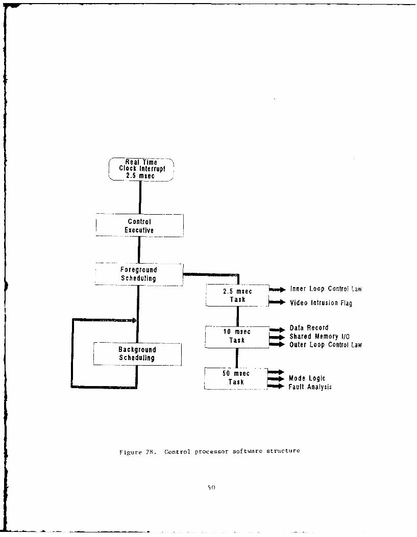
Software Structure
The major functions and structure of the softwareimplementation for the AECU are presented in figures 27 and28. This software performs all the computations, logic,and signal management functions required for the AECUoperation.
Executive Processing
The software structure is divided into the main orexecutive processor and the control processor structure.The executive processor preforms the following functions
startup and shutdownInterrupt processingexecutiveframe synchronizationforeground schedulingmiddle ground schedulingbackground scheduling
This structure is illusrated in figure 27.
Control Loop Processing
Control loop processing performs similar tasks to theexecutive processor, but is running on a 2.5 millisecondclock. Its basic task is to perform the inner and outercontrol law computations, plus set up the logic for each ofthe degrees of freedom. This software structure is shownin figure 28.
1/0 Processing
The i/O processing takes the signals from each of thesensors and makes them available to the control lawcomputation. The control processor also looks at theshared memory for discrete and command update and placesinformation about the control processor status there forthe executive processor to use.
48

Power OnInterrupt
/ Real Time IClock Interrupt\ 10 msec /
\)9~rsec /Iniltiaization
Executive
Shared MemoryForegound O Commands
Scheduling _ Vision Intrusion
7717 Command
1553 Communication
Middle Ground Non- Critical Vision CommunicationSche. uling
Critical BIT
Error
-" a Back 9 oundScheduling - Built- In Test
i-i
Figure 27. Executive processor software structure
49
Real TimeClock Interrupt
2.5 msec
ControlExecutive
ForegroundScheduling I,-=
2.5 msec Inner Loop Contr& LawTask Video Intrusion Flag
F 0 msec Data Record
Task Shared Memory I/0r- Background L Outer Loop Control Law
Scheduling
50 msec Mode Logic,_I Tas k Fault Analysis
Figure 28. Control processor software structure
50
. ...!..
Control Laws
The control laws can be broken into several segments;the first is the inner loop closure, and the second theouter loop closure. The design of the control laws followthe optimal control method of least acceleration control tosatisfy the position and rate requirements. This methodgenerally assures smooth operation and consistentpositional accuracy. The derivation of these laws are donein the Z domain so as to eliminate the analog phase of theprogram.
51

CONCLUSIONS
I. A single generic Advanced Electronic ControlUnit can be designed and built to control a variety ofmilitary laboratory and combat autoloaders and robots.Current processor technology makes an all-digital commandand control package possible, allowing for tailoring ofboth command sequences and logic associated with differentautoloaders, and of the different dynamic requirements ofthe control loops. Using digital cards will also allow theimplementation of state space and other modern controltechniques.
2. The mechanical configurations studied to performthe autoloading task were found to have similarrequirements as far as sensors and actuation, allowing ageneric controller as that proposed to be effectively used,with a minimum of compromises, in conjunction withdifferent mechanical and robotic systems.
3. The controller can be modularized so that onlythe required electronic cards for a given mechanical systemneed be implemented. This modularity includes electroniccommonality with other Army systems, notably the LHX familyof helicopters.
4. Vision technology is shown to provideoperational benefits, including safety and dissimilarsensor redundancy. The contro]ler is designed to interfacewith such a system.
52
RECOMMENDATIONS
There are several aspects of a Phase II AdvancedElectronic Control Unit development project that should bepursued. These are briefly outlined below. A moredetailed presentation of each of these aspects is given inthe Phase TI proposal, submitted to ARDEC under separatecover.
1. Vista Controls feels that the most effective wayto prove the generic controller concept is to refurbish theexisting ISAS robotic autoloader system and build aprototype generic controller to demonstrate the advantagesof the all-digital approach. The ISAS robot is ideal forthis purpose on several accounts, including:
a. It is already built and has been extensivelytested.
b. The overall system (robot, flick loader tray,and breech) makes use of all the types of control loopsexpected on future howitzer autoloaders.
c. It is already configured for the autoloaderprocess, as opposed to a laboratory, industrial-type robot.
Several basic areas for modification would beexplored. The mechanical components and sensors would bemodified to provide improved dynamic performance.Redundant sensors would be incorporated, and logic would beprogrammed to provide degraded modes of operation andimprove the failure tolerance.
With this modified ISAS as the baseline mechanicalsystem, the AECU would be built and integrated into thesystem. Improved digital high-bandwidth servo controlwould be incorporated and demonstrated to speed up theautoloader response time. The programmability and humaninterface aspects would be demonstrated. A vision systemwould be installed to demonstrate the safety and sensorredundancy benefits.
2. As a more advanced option, Vista Controls wouldbuild a prototype transfer unit, magazine and autofuzer inaddition to the generic controller to demonstrateoperation, including the use of advanced control concepts.This mechanical system would be based on the resultspresented in this study.
We feel that significant advantages would be gained bythis approach. The generic controller concept would bedemonstrated identically as proposed in Item I above. Inaddition, advanced autoloader concepts would be proved.Vista Controls feels that these concepts fit in directly
53

with the HIP and AFAS present and future requirements, asoutlined in this study and in the AFAS RequirementsOverview paper (ref. 3).
54
References
1. Paul Hoffman, "Integrated Smart Artillery Synthesis(ISAS) Progress Report, October 1983 through September1985," technical note 85-003, ARRADCOM, Dover, NJ,December 1985.
2. "Artillery Industry Day," program handout, U. S. ArmyField Artillery School, ARDEC, Picatinny Arsenal,Dover, NJ, 10 October 1986.
3. "Requirements Overview for the Integration of theHowitzer Improvement Program (HIP) and Advanced FieldArtillery System (AFAS)," paper submitted in responseto solicitations of ideas, Artillery Industry Day,Document #119-001, Vista Controls Corp., Valencia, CA,10 November 1986.
4. Jay S. Coke, Lloyd M. Grumley, and Robert C. Schwalm,"Emplacing, Firing, and March ordering an M1O9A1Howitzer: Tasks and Task Times," research report 1312,ARI Field Unit at Fort Sill, OK, June 1981.
5. John J. Scheurich, Gary J. Nelson, Stephen G. Floroff,"Demonstrator Prototype Automated Ammunition Handlingand Loading System for a 155-mm Self-PropelledHowitzer Test Bed," ARRADCOM contractor report ARLCD-CR-61053, FMC Corp., Minneapolis, MN, December 1981.
6. "Conceptual Design of a Rotating Breech AutomatedAmmunition Handling System, Final Report," ARRADCOMcontractor report DAAK10-79-C-0164, Chrysler Corp., 14February 1980.
55

Bibliography
1. James W. Baumgart, M. Paul Stanton, Russell R. Vane,Division Suppo .WeapnsSYtem Rate of Fire and C3Operations, ARRADCOM contractor report DAEA 18-81-6-0017 ET01 01, Science Applications, Inc., McLean, VA,1 April 1983.
2. Barry L. Reichard, Alan R. Downs, A Compendium ofField Artillery Facts, U. S. Army Ballistics ResearchLaboratories report 1759, Aberdeen Proving Grounds,MD, February 1975.
3. Field Artllery CannonWeaponpSystems and AmmunitionHandbook, U. S. Army Field Artillery School, WeaponsDept., Fort Sill, OK, February 1983.
4. 155-mm Self-Propelled Howitzer Lturre t), DTIC repor':ADB020769, Nippon seiko-sho, Inc., Japan, 1972.
5. Robotic Resu~pplySysitem for 155-mm ArtilleryAmmunition, Volume 1, BMY's Concept, ARRADGOMcontractor report ARFSD-CR-86013, BMY, York, PA, andMartin Marietta, Baltimore, MD, July 1986.
6. RoboticResqpp._y_ System for 155-mm ArtilleryAmmunition, Volume 3, Howden ColonelL Inc.'s Concept,ARRADCOM contractor report ARFSD-CR-86013, HowdenColoney, Inc., Tallahassee, FL, July 1986.
57
DISTRIBUTION LIST
CommanderArmament Research, Development
and Engineering Center
U.S. Army Armament, Munitions
and Chemical Command
ATTN: SMCAR-MSI (5)SMCAR-FSA-F (15)
Picatinny Arsenal, NJ 07806-5000
Commander
U.S. Army Armament, Munitions
and Chemical CommandATTN: AMSMC-GCL(D)
AMSMC-DAR-R(D)
Picatinny Arsenal, NJ 07806-5000
Administrator
Defense Technical Information Center
ATTN: Accessions Division (12)
Cameron Station
Alexandria, VA 22304-6145
Director
U.S. Army Materiel SystemsAnalysis Activity
ATTN: AXSY-MP
Aberdeen Proving Ground, MD 21005-5066
CommanderChemical Research, Development
and Engineering Center
U.S. Army Armament, Munitions
and Chemical CommandATTN: SMCCR-MSI
SMCC R-CL J- L
SMCCR- CLB-PA
Aberdeen Proving Ground, MD 21010-5423
CommanderChemical Research, Development
and Fngineering CenterU.S. Army Armament, Munitions
and Chemical CommandATTN: SMCCR-RSP-A
Aberdeen Proving Ground, MD 21010-5423
DirectorBallistic Research Laboratory
ATTN: AMXBR-OD-STAberdeen Proving Ground, MD 21005-5066
59
ChiefBenet Weapons Laboratory, CCACArmament Research, Development and Ehgineering Center
U.S. Army Armament, Munitionsand Chemical Command
ATTN: SMCAR-CCB-TLWatervliet, NY 12189-5000
CommanderU.S. Army Armament, Munitions
and Chemical CommandATTN: SMCAR-ESP-LRock Island, IL 61299-6000
DirectorU.S. Army TRADOC Systems
Analysis ActivityATTN: ATAA-SLWhite Sands Missile Range, NM 88002
60

DATE
,FILM ED