z/os rmf programmer's guide - ibm · locksp - t abular r eport data table erblspt3 280 locksu...
TRANSCRIPT

z/OS
Resource Measurement FacilityProgrammer's GuideVersion 2 Release 3
SC34-2667-30
IBM

NoteBefore using this information and the product it supports, read the information in “Notices” on page 325.
This edition applies to Version 2 Release 3 of z/OS (5650-ZOS) and to all subsequent releases and modificationsuntil otherwise indicated in new editions.
Last updated: December 22, 2017
© Copyright IBM Corporation 1990, 2017.US Government Users Restricted Rights – Use, duplication or disclosure restricted by GSA ADP Schedule Contractwith IBM Corp.

Contents
Figures . . . . . . . . . . . . . . vii
Tables . . . . . . . . . . . . . . . ix
About this document . . . . . . . . . xiWho should use this document . . . . . . . . xiHow this document is organized . . . . . . . xiz/OS information . . . . . . . . . . . . xiiHow to read syntax diagrams . . . . . . . . xiii
Symbols . . . . . . . . . . . . . . xiiiSyntax items . . . . . . . . . . . . . xiiiSyntax examples . . . . . . . . . . . xiv
How to send your comments to IBM xviiIf you have a technical problem . . . . . . . xvii
Summary of changes . . . . . . . . xixChanges for z/OS Version 2 Release 3 . . . . . xixChanges for z/OS Version 2 Release 2 . . . . . xxSummary of changes for z/OS RMF Programmer'sGuide for Version 2 Release 1, as updated February2015 . . . . . . . . . . . . . . . . xxiChanges for z/OS Version 2 Release 1 . . . . . xxi
z/OS Version 2 Release 1 summary of changes xxii
Chapter 1. SMF records . . . . . . . . 1Overview . . . . . . . . . . . . . . . 1SMF record format . . . . . . . . . . . . 2Archived performance data . . . . . . . . . 4
RMF version numbers . . . . . . . . . . 4Printing SMF records . . . . . . . . . . . 5
Using the IDCAMS utility . . . . . . . . . 5Using the ERBSCAN utility . . . . . . . . 6
Obtaining SMF record data directly . . . . . . . 8Registers at entry . . . . . . . . . . . . 8Parameter list contents . . . . . . . . . . 8Output . . . . . . . . . . . . . . . 11Return codes . . . . . . . . . . . . . 12Coded example . . . . . . . . . . . . 13
Chapter 2. RMF sysplex data services 15How to call sysplex data services . . . . . . . 15
How to call sysplex data services in 64-bit mode 16ERBDSQRY - RMF Query available sysplex SMFdata service . . . . . . . . . . . . . . 16ERBDSREC - RMF Request sysplex SMF record dataservice . . . . . . . . . . . . . . . . 20ERB2XDGS - RMF Monitor II sysplex data gatheringservice . . . . . . . . . . . . . . . . 21ERB2XDGS data reduction exit routines . . . . . 24ERB3XDRS - RMF Monitor III sysplex data retrievalservice . . . . . . . . . . . . . . . . 26ERB3XDRS data reduction exit routines . . . . . 29Return codes and reason codes . . . . . . . . 31
Layout of RMF callable services answer area . . . 36Layout of common answer area header . . . . 36ERBDSQRY/ERBDSQ64 data section layout . . 38ERBDSREC/ERBDSR64 data section layout. . . 39ERB2XDGS/ERB2XD64 data section layout . . . 40ERB3XDRS/ERB3XD64 data section layout . . . 41
Chapter 3. Accessing performance datausing the RMF Distributed Data Server . 45How to specify HTTP requests to the DDS forperformance data . . . . . . . . . . . . 46
Understanding the underlying resource models 46Structure of DDS requests . . . . . . . . 50Description and purpose of parameters . . . . 51How to specify different types of requests . . . 59
How to interpret an XML document returned by theDDS . . . . . . . . . . . . . . . . . 63
Description of the XML document structure . . 63SMF-Input element . . . . . . . . . . . 65Attribute-List element. . . . . . . . . . 65Contained-Resources-List element . . . . . . 67Filter-Instances-List element . . . . . . . 69Message . . . . . . . . . . . . . . 69Metric-List element . . . . . . . . . . 70Postprocessor element . . . . . . . . . . 72Report element . . . . . . . . . . . . 78Workscope-List element . . . . . . . . . 82RMF-MFP-Message element . . . . . . . . 83Coding example for requesting and receivingMonitor III performance data . . . . . . . 83
Chapter 4. z/OS CIM monitoring . . . . 85z/OS RMF CIM monitoring . . . . . . . . . 85z/OS resource classes based on RMF . . . . . . 87
IBMz_CEC . . . . . . . . . . . . . 88IBMz_ComputerSystem . . . . . . . . . 88IBMzOS_Channel . . . . . . . . . . . 90IBMzOS_WLMServiceDefinition . . . . . . 90IBMzOS_WLMServiceClassPeriod . . . . . . 90
z/OS metrics . . . . . . . . . . . . . . 91IBMzOS_LogicalDisk . . . . . . . . . . 91IBMz_CEC . . . . . . . . . . . . . 94IBMz_ComputerSystem . . . . . . . . . 100IBMzOS_OperatingSystem . . . . . . . . 107IBMzOS_ComputerSystem . . . . . . . . 114IBMzOS_Process . . . . . . . . . . . 115IBMzOS_UnixProcess . . . . . . . . . . 116IBMzOS_Channel . . . . . . . . . . . 117IBMzOS_UnixLocalFileSystem . . . . . . . 119
Chapter 5. Adding Monitor I andMonitor II installation exits . . . . . 121Overview. . . . . . . . . . . . . . . 121Monitor I session user reports . . . . . . . . 121
Guidelines . . . . . . . . . . . . . 122
© Copyright IBM Corp. 1990, 2017 iii
||
||

Initialization for Monitor I session user exitroutines . . . . . . . . . . . . . . 122Sampling data at each cycle . . . . . . . 123Interval processing . . . . . . . . . . 124Report writing during session processing . . . 125Termination . . . . . . . . . . . . . 125Tracing your own field . . . . . . . . . 126Report writing by the Postprocessor . . . . . 128Adding your routines to RMF . . . . . . . 128
Monitor II session user reports . . . . . . . 129Guidelines . . . . . . . . . . . . . 130SMF record type 79 . . . . . . . . . . 130Coding a user report . . . . . . . . . . 134Installing a user report . . . . . . . . . 140Using the PICTURE macro . . . . . . . . 143TSO terminal user authorization . . . . . . 145
Chapter 6. Adding Monitor III userexits . . . . . . . . . . . . . . . 147Overview. . . . . . . . . . . . . . . 147
Data gathering . . . . . . . . . . . . 147Reporting . . . . . . . . . . . . . 147Invoking user reports. . . . . . . . . . 147Measurement data. . . . . . . . . . . 148
Data gatherer sample structure . . . . . . . 148Data gatherer control blocks . . . . . . . 150
Programming a data gatherer . . . . . . . . 151Data reporter phases . . . . . . . . . . . 153The Monitor III utility . . . . . . . . . . 154
Report utility panel flow . . . . . . . . 154Before you start the utility . . . . . . . . 155Starting the report utility . . . . . . . . 156Example - Modified SYSINFO report . . . . 156Report format definition panel (ERB3RD1) . . 158Phase driver information panel (ERB3RD2) . . 159Report format information panel (ERB3RD3) 161Report header layout panels (ERB3RD4 andERB3RD5) . . . . . . . . . . . . . 163Report subheader layout panels (ERB3RD6 andERB3RD7) . . . . . . . . . . . . . 165Report column layout panels (ERB3RD8 andERB3RD9) . . . . . . . . . . . . . 167Command line layout panel (ERB3RDA) . . . 169Graphic parameter definition panels (ERB3RDB,ERB3RDC, ERB3RDD) . . . . . . . . . 170Saving or cancelling changes on panel ERB3RDF 174Deleting a user-defined report . . . . . . . 175Ending the report utility. . . . . . . . . 176Implementing the report. . . . . . . . . 176Special considerations for modifying reports . . 178Installing your own phases . . . . . . . . 178Data retrieval service (ERB3RDRS) . . . . . 182
TSO/E user authorization . . . . . . . . . 185
Chapter 7. Using Monitor III VSAMdata set support . . . . . . . . . . 187Data set record structure . . . . . . . . . 187Data set decompression . . . . . . . . . . 188
Programming considerations . . . . . . . 188Registers at entry . . . . . . . . . . . 188
Parameter area contents . . . . . . . . . 189Output . . . . . . . . . . . . . . 189Return codes . . . . . . . . . . . . 189Coded example. . . . . . . . . . . . 189
Data set content . . . . . . . . . . . . 191Monitor III data set record and table formats . . . 194
ERBASIG3 - Address space identification table 194ERBCATG3 - Cache data information table . . 201ERBCFIG3 - Coupling facility information table 202ERBCPCDB - CPC data control block . . . . 210ERBCPDG3 - Channel data table . . . . . . 215ERBCPUG3 - Processor data control block . . . 218ERBCSRG3 - Common storage remaining table 219ERBDSIG3 - Data set header and index. . . . 220ERBDVTG3 - Device table . . . . . . . . 221ERBENCG3 - Enclave data table . . . . . . 223ERBENTG3 - Enqueue name table . . . . . 227ERBGEIG3 - General information table . . . . 228ERBGGDG3 - Global gatherer data table . . . 233ERBOPDG3 - OMVS process data table. . . . 241ERBRCDG3 - Resource collection data . . . . 243ERBREDG3 - Resource data record . . . . . 249ERBSHDG3 - Sample header . . . . . . . 249ERBSPGG3 - Storage group and volume data 250ERBSSHG3 - MINTIME set of samples header 251ERBSVPG3 - Service policy . . . . . . . . 253ERBUWDG3 - USE/WAIT record. . . . . . 257ERBXMHG3 - Moved samples header controlblock . . . . . . . . . . . . . . . 258
Chapter 8. Monitor III data reportertables. . . . . . . . . . . . . . . 261Tabular report format table ERBFMTS3 . . . . . 261Header data table ERBHDRS3 . . . . . . . . 263Monitor III data reporter tables . . . . . . . 263
CACHDET - Tabular report data tableERBCADT3 . . . . . . . . . . . . . 263CACHSUM - Tabular report data tableERBCAST3 . . . . . . . . . . . . . 265CFACT - Tabular report data table ERBCFAT3 266CFOVER - Tabular report data table ERBCFOT3 268CFSYS - Tabular report data table ERBCFST3 269CHANNEL - Tabular report data tableERBCHAT3 . . . . . . . . . . . . . 270CPC - Tabular report data table ERBCPCT3 . . 271DELAY - Tabular report data table ERBJDET3 273DEV - Tabular report data table ERBDEVT3 . . 274DEVR - Tabular report data table ERBDVRT3 274DI - Tabular report data table ERBDSIT3 . . . 275DSND - Tabular report data table ERBDNDT3 275DSNJ - Tabular report data table ERBDNJT3 . . 276DSNV - Tabular report data table ERBDNVT3 276ENCLAVE - Tabular report data tableERBENCT3 . . . . . . . . . . . . . 276ENQ - Tabular report data table ERBENQT3 . . 278ENQR - Tabular report data table ERBEQRT3 278HSM - Tabular report data table ERBHSMT3 278IOQUEUE - Tabular report data tableERBIOQT3 . . . . . . . . . . . . . 279JES - Tabular report data table ERBJEST3 . . . 279JOB - Tabular report data table ERBJDJT3 . . . 279
iv z/OS RMF Programmer's Guide

LOCKSP - Tabular report data table ERBLSPT3 280LOCKSU - Tabular report data table ERBLSUT3 280OPD - Tabular report data table ERBOPDT3 . . 281PCIE – Tabular report data table ERBPCIT3 . . 282PROC - Tabular report data table ERBPRCT3 283PROCU - Tabular report data table ERBPRUT3 284RLSDS - Tabular report data table ERBVRDT3 285RLSLRU - Tabular report data table ERBVRLT3 285RLSSC - Tabular report data table ERBVRST3 286SCM - Tabular report data table ERBSCMT3 . . 286SPACED - Tabular report data table ERBSPDT3 287SPACEG - Tabular report data table ERBSPGT3 287STOR - Tabular report data table ERBSTRT3 . . 288STORC - Tabular report data table ERBCSUT3 288STORCR - Tabular report data table ERBCRST3 289STORF - Tabular report data table ERBSTFT3 289STORM - Tabular report data table ERBSTMT3 290STORR - Tabular report data table ERBSRRT3 292STORS - Tabular report data table ERBSRST3 292SYSENQ - Tabular report data table ERBEQST3 293SYSINFO - Tabular report data table ERBSYST3 293SYSRTD - Tabular report data table ERBRTDT3 296SYSSUM - Tabular report data table ERBSUMT3 297SYSWKM - Tabular report data tableERBWKMT3. . . . . . . . . . . . . 298USAGE - Tabular report data table ERBJUST3 298WFEX - Tabular report data table ERBWFXT3 299XCF - Tabular report data table ERBXCFT3 . . 299ZFSFS - Tabular report data table ERBZFFT3 300ZFSKN - Tabular report data table ERBZFKT3 301ZFSOVW - Tabular report data table ERBZFOT3 301
Graphic report parameter table ERBPTGS3 . . . 302RMF Phase driver table ERBPHDS3 . . . . . . 305
Chapter 9. Diagnosing problems inRMF . . . . . . . . . . . . . . . 307Identifying problems . . . . . . . . . . . 307
Diagnosing abend 0D5 . . . . . . . . . . 307Diagnosing abend 0FE . . . . . . . . . . 309Diagnosing an abend unexpected by RMF. . . . 310Diagnosing a message with an ERB prefix . . . . 311Diagnosing a message with a CEE/EDC prefix . . 311Diagnosing incorrect output . . . . . . . . 312Diagnosing a documentation error . . . . . . 313Diagnosing an empty Monitor III JES Delays report 313Obtaining a dump from Monitor II or Monitor III 314Developing a search argument for RMF . . . . 314Reporting a problem to IBM . . . . . . . . 315
Appendix. Accessibility . . . . . . . 321Accessibility features . . . . . . . . . . . 321Consult assistive technologies . . . . . . . . 321Keyboard navigation of the user interface . . . . 321Dotted decimal syntax diagrams . . . . . . . 321
Notices . . . . . . . . . . . . . . 325Terms and conditions for product documentation 327IBM Online Privacy Statement. . . . . . . . 328Policy for unsupported hardware. . . . . . . 328Minimum supported hardware . . . . . . . 328Exploitation of the Flash Express feature . . . . 329Programming Interface Information . . . . . . 329Trademarks . . . . . . . . . . . . . . 329
Glossary . . . . . . . . . . . . . 331
Index . . . . . . . . . . . . . . . 337
Contents v

vi z/OS RMF Programmer's Guide

Figures
1. SMF Record Format . . . . . . . . . . 32. Dump Format of SMF Record . . . . . . . 63. ERBSCAN - Display RMF Record List . . . . 64. ERBSHOW - Display RMF Record Header 75. ERBSHOW - Display Device Data Section 76. Parameter list for a command to obtain SMF
record data. . . . . . . . . . . . . 117. Format of the start time . . . . . . . . 188. Example: How to use the DDS HTTP API in a
z/OS environment . . . . . . . . . . 459. The z/OS RMF Monitor III resource model 47
10. The AIX resource model . . . . . . . . 4811. The Linux on System x resource model 4912. The Linux on System z resource model 4913. z/OS RMF implementation of the DMTF
dynamic metrics model . . . . . . . . 8614. z/OS resource classes implemented by RMF 8815. ERBMFIUC Input Parameter Structure 12316. User Sampler Input Parameter Structure 12417. ERBMFDUC Input Parameter Structure 12518. ERBMFRUR Input Parameter Structure 12519. ERBMFTUR Input Parameter Structure 12620. Example of Adding a Name to ERBMFTTB 12721. ERBTRACE Input Parameter Structure 12722. ERBMFPUS Input Parameter Structure 12823. Replacing Installation Exits . . . . . . . 12924. Adding a User Sampler . . . . . . . . 12925. ERBSMF79 Mapping Macro Expansion 13126. ERBSMF79 Mapping Macro Expansion
(continued) . . . . . . . . . . . . 13227. Install User Report . . . . . . . . . . 14228. Syntax of the PICTURE Macro . . . . . . 14329. ERBTSOCK Input Parameter Structure 14530. Data Gatherer Sample Structure . . . . . 14931. Mapping Macros of ERBSSHG3, ERBSHDG3
and ERBREDG3. . . . . . . . . . . 150
32. Panel Sequence for the Report DefinitionUtility . . . . . . . . . . . . . . 155
33. SYSINFO Report . . . . . . . . . . 15734. SYSCPU Report as Modification of the
SYSINFO Report . . . . . . . . . . 15835. Report Definition Initialization Panel
ERB3RD1 . . . . . . . . . . . . . 15936. Phase Driver Information Panel (ERB3RD2) 16037. Report Format Information Panel (ERB3RD3) 16238. Report Header Layout Panel (ERB3RD4) 16439. Report Header Layout Panel (ERB3RD5) 16540. Report Subheader Layout Panel (ERB3RD6) 16641. Report Subheader Layout Panel (fERB3RD7) 16742. Report Column Layout Panel (ERB3RD8) 16843. Report Column Layout Panel (ERB3RD9) 16944. Command Line Layout Panel (ERB3RDA) 17045. Graphic Parameter Definition Panel
(ERB3RDB) . . . . . . . . . . . . 17146. Graphic Parameter Definition Panel
(ERB3RDC) . . . . . . . . . . . . 17247. Graphic Parameter Definition Panel
(ERB3RDD) . . . . . . . . . . . . 17348. Configuration/Cancellation Panel (ERB3RDF) 17449. Initial Version of the SYSCPU Report 17550. Modifications in User Selection Menu
Definition (ERB3USR) - Part 1 . . . . . . 17651. Modifications in User Selection Menu
Definition (ERB3USR) - Part 2 . . . . . . 17752. Modified User Selection Menu (ERB3USR) 17753. ERB3SOCK Input Parameter Structure 18654. Monitor III Data Set Record. . . . . . . 18855. Monitor III Measurement Table and Record
Relationships . . . . . . . . . . . 193
© Copyright IBM Corp. 1990, 2017 vii
|||||

viii z/OS RMF Programmer's Guide

Tables
1. Syntax examples . . . . . . . . . . xiv2. Return Codes for the Monitor II Data Interface
Service . . . . . . . . . . . . . . 123. Sysplex data services . . . . . . . . . 164. ERBDSQRY Service . . . . . . . . . . 175. ERBDSREC Service . . . . . . . . . . 206. ERB2XDGS Service . . . . . . . . . . 227. ERB2XDGS Exit Routine . . . . . . . . 258. ERB3XDRS Service . . . . . . . . . . 269. ERB3XDRS Exit Routine . . . . . . . . 29
10. RMF Sysplex Data Services Return and ReasonCodes (SMF Services) . . . . . . . . . 32
11. Request parameters . . . . . . . . . . 5112. Valid filename specifications . . . . . . . 5913. Return Codes from the Data Gatherer and
Data Reporter . . . . . . . . . . . 13614. Return and Reason Codes for the Data
Retrieval Service (ERB3RDRS) . . . . . . 18415. Return Codes for the Data Set Decompression
Interface Service . . . . . . . . . . 18916. Problem Types . . . . . . . . . . . 30717. Diagnostic Procedure for Abend 0D5 30718. Diagnostic Procedure for Abend 0FE 30919. Diagnostic Procedure for an Abend
Unexpected by RMF . . . . . . . . . 310
20. Diagnostic Procedure for a Message with anERB Prefix . . . . . . . . . . . . 311
21. Diagnostic Procedure for a Message with aCEE/EDC Prefix . . . . . . . . . . 312
22. Diagnostic Procedure for Incorrect Output 31223. Diagnostic Procedure for a Documentation
Error . . . . . . . . . . . . . . 31324. Diagnostic Procedure for Empty Monitor III
JES Delays Report . . . . . . . . . . 31425. Search Arguments from Diagnostic
Procedures . . . . . . . . . . . . 31526. Checklist for Reporting a Problem with an
Abend 0D5 . . . . . . . . . . . . 31527. Checklist for Reporting a Problem with an
Abend 0FE . . . . . . . . . . . . 31628. Checklist for Reporting a Problem with an
Unexpected Abend. . . . . . . . . . 31729. Checklist for Reporting a Problem with an
ERB CEE/EDC Message . . . . . . . . 31730. Checklist for Reporting a Problem with
Incorrect Output . . . . . . . . . . 31831. Checklist for Reporting a Documentation
Error . . . . . . . . . . . . . . 31832. Checklist for Reporting a Problem with a
Monitor III JES Delays Report . . . . . . 318
© Copyright IBM Corp. 1990, 2017 ix

x z/OS RMF Programmer's Guide

About this document
The Resource Measurement Facility™ (RMF™) is a performance management toolthat measures selected areas of system activity and presents the data collected inthe form of System Management Facility (SMF) records, formatted printed reports,or formatted display reports. You can use this data to evaluate system performanceand identify reasons for performance problems.
This document contains information and reference material to enable you to useRMF data for application programming. There is a number of different ways ofgetting at different kinds of information, and each one is described in a separatechapter of this document.
Further processing of RMF report data can also be done using spreadsheets. TheSpreadsheet Reporter is described in the z/OS RMF User's Guide.
In addition, this document is describing diagnosis procedures that can be used incase of an error when running RMF.
Who should use this documentThis document is intended for use by system programmers responsible for thedevelopment of individual, installation-specific applications in the area of systemmeasurement. Because RMF is a tool for measuring MVS™ system performance,this document assumes that the reader has extensive knowledge of the MVSsystem.
For an overview of RMF, and guidance on using the standard capabilities of theproduct, see the z/OS RMF User's Guide.
How this document is organizedThis document contains the following chapters:
Chapter 1, “SMF records,” on page 1These are the records from which RMF obtains information for thestandard reports. You can find all the information you need to use themfor your own reports in this chapter.
Chapter 2, “RMF sysplex data services,” on page 15These are callable services with which you as an RMF user can accessperformance data sysplex-wide. The calls, return codes and data layoutsare described here.
Chapter 3, “Accessing performance data using the RMF Distributed DataServer,” on page 45
Application programs which want to retrieve sysplex-wide performancedata can use the HTTP API of the Distributed Data Server (DDS). The DDSgathers data from the RMF instances running on the sysplex members. Anapplication program can send an HTTP request for selected performancemetrics to the DDS. The DDS returns the requested RMF data as astructured XML document. Thus, exploiters of the DDS HTTP API haveinstant access to a great variety of z/OS performance metrics includingshort-term information as well as long-term historical data.
© Copyright IBM Corp. 1990, 2017 xi

RMF also provides CIM-based performance data gatherers for AIX® onSystem x, Linux on System x, and Linux on System z®. Therefore,exploiters of the DDS HTTP API can send an HTTP request to retrieveperformance data from the endpoints running the supported Linux or AIXoperating systems.
This topic describes how to specify HTTP requests to the DDS forperformance data and how to interpret an XML document returned by theDDS.
Chapter 4, “z/OS CIM monitoring,” on page 85With z/OS V1.7 base element Common Information Model (CIM), it ispossible to use the DMTF CIM open standard for systems management.z/OS CIM implements the CIM server which is based on the OpenPegasusopen source project. A CIM monitoring client invokes the CIM serverwhich, in turn, collects z/OS metrics from the system and returns it to thecalling client. To get the z/OS metrics, the CIM server invokes the z/OSRMF monitoring provider which retrieves the metrics associated with z/OSsystem resources. The z/OS RMF monitoring provider uses existing andextended RMF Monitor III performance data.
The z/OS metrics obtained by z/OS CIM are described in this topic. Theyare common across eServer™ platforms, so you can use them to createend-to-end monitoring applications.
Chapter 5, “Adding Monitor I and Monitor II installation exits,” on page 121You can enhance the gathering capabilities of Monitor I and add your ownreport types to Monitor II by writing your own exit routines. Details oncoding and installing these exit routines are given in this chapter.
Chapter 6, “Adding Monitor III user exits,” on page 147The RMF Monitor III Utility helps you to add your own processing to thestandard Monitor III reporting. This chapter describes this utility and itsusage.
Chapter 7, “Using Monitor III VSAM data set support,” on page 187The processing and format of the VSAM data sets that Monitor III uses tostore its information are described in this chapter.
Chapter 8, “Monitor III data reporter tables,” on page 261When coding Monitor III exit routines, for example, with the help of theMonitor III Utility, you have to know what information RMF has storedwhere for use in which reports. The data is stored in tables, and thelayouts of these are shown here.
Chapter 9, “Diagnosing problems in RMF,” on page 307In this chapter, you find procedures that you might use in case of an errorwhen running RMF.
z/OS informationThis information explains how z/OS references information in other documentsand on the web.
When possible, this information uses cross document links that go directly to thetopic in reference using shortened versions of the document title. For completetitles and order numbers of the documents for all products that are part of z/OS,see z/OS Information Roadmap.
xii z/OS RMF Programmer's Guide
|||||

To find the complete z/OS® library, go to IBM Knowledge Center(www.ibm.com/support/knowledgecenter/SSLTBW/welcome).
How to read syntax diagramsThis section describes how to read syntax diagrams. It defines syntax diagramsymbols, items that may be contained within the diagrams (keywords, variables,delimiters, operators, fragment references, operands) and provides syntax examplesthat contain these items.
Syntax diagrams pictorially display the order and parts (options and arguments)that comprise a command statement. They are read from left to right and from topto bottom, following the main path of the horizontal line.
For users accessing the Information Center using a screen reader, syntax diagramsare provided in dotted decimal format.
SymbolsThe following symbols may be displayed in syntax diagrams:
SymbolDefinition
►►─── Indicates the beginning of the syntax diagram.
───► Indicates that the syntax diagram is continued to the next line.
►─── Indicates that the syntax is continued from the previous line.
───►◄ Indicates the end of the syntax diagram.
Syntax itemsSyntax diagrams contain many different items. Syntax items include:v Keywords - a command name or any other literal information.v Variables - variables are italicized, appear in lowercase, and represent the name
of values you can supply.v Delimiters - delimiters indicate the start or end of keywords, variables, or
operators. For example, a left parenthesis is a delimiter.v Operators - operators include add (+), subtract (-), multiply (*), divide (/), equal
(=), and other mathematical operations that may need to be performed.v Fragment references - a part of a syntax diagram, separated from the diagram to
show greater detail.v Separators - a separator separates keywords, variables or operators. For example,
a comma (,) is a separator.
Note: If a syntax diagram shows a character that is not alphanumeric (forexample, parentheses, periods, commas, equal signs, a blank space), enter thecharacter as part of the syntax.
Keywords, variables, and operators may be displayed as required, optional, ordefault. Fragments, separators, and delimiters may be displayed as required oroptional.
Item typeDefinition
About this document xiii

RequiredRequired items are displayed on the main path of the horizontal line.
OptionalOptional items are displayed below the main path of the horizontal line.
DefaultDefault items are displayed above the main path of the horizontal line.
Syntax examplesThe following table provides syntax examples.
Table 1. Syntax examples
Item Syntax example
Required item.
Required items appear on the main path of thehorizontal line. You must specify these items.
►► KEYWORD required_item ►◄
Required choice.
A required choice (two or more items) appearsin a vertical stack on the main path of thehorizontal line. You must choose one of theitems in the stack.
►► KEYWORD required_choice1required_choice2
►◄
Optional item.
Optional items appear below the main path ofthe horizontal line.
►► KEYWORDoptional_item
►◄
Optional choice.
An optional choice (two or more items)appears in a vertical stack below the main pathof the horizontal line. You may choose one ofthe items in the stack.
►► KEYWORDoptional_choice1optional_choice2
►◄
Default.
Default items appear above the main path ofthe horizontal line. The remaining items(required or optional) appear on (required) orbelow (optional) the main path of thehorizontal line. The following example displaysa default with optional items.
►►default_choice1
KEYWORDoptional_choice2optional_choice3
►◄
Variable.
Variables appear in lowercase italics. Theyrepresent names or values.
►► KEYWORD variable ►◄
Repeatable item.
An arrow returning to the left above the mainpath of the horizontal line indicates an itemthat can be repeated.
A character within the arrow means you mustseparate repeated items with that character.
An arrow returning to the left above a groupof repeatable items indicates that one of theitems can be selected,or a single item can berepeated.
►► ▼KEYWORD repeatable_item ►◄
►► ▼
,
KEYWORD repeatable_item ►◄
xiv z/OS RMF Programmer's Guide

Table 1. Syntax examples (continued)
Item Syntax example
Fragment.
The fragment symbol indicates that a labelledgroup is described below the main syntaxdiagram. Syntax is occasionally broken intofragments if the inclusion of the fragmentwould overly complicate the main syntaxdiagram.
►► KEYWORD fragment ►◄
fragment:
,required_choice1,default_choice
,required_choice2,optional_choice
About this document xv

xvi z/OS RMF Programmer's Guide

How to send your comments to IBM
We appreciate your input on this documentation. Please provide us with anyfeedback that you have, including comments on the clarity, accuracy, orcompleteness of the information.
Use one of the following methods to send your comments:
Important: If your comment regards a technical problem, see instead “If you havea technical problem.”v Send an email to [email protected] Send an email from the Contact z/OS web page (www.ibm.com/systems/z/os/
zos/webqs.html).
Include the following information:v Your name and addressv Your email addressv Your phone or fax numberv The publication title and order number:
z/OS RMF Programmer's GuideSC34-2667-30
v The topic and page number or URL of the specific information to which yourcomment relates
v The text of your comment.
When you send comments to IBM®, you grant IBM a nonexclusive right to use ordistribute the comments in any way appropriate without incurring any obligationto you.
IBM or any other organizations use the personal information that you supply tocontact you only about the issues that you submit.
If you have a technical problemDo not use the feedback methods that are listed for sending comments. Instead,take one or more of the following actions:v Visit the IBM Support Portal (support.ibm.com).v Contact your IBM service representative.v Call IBM technical support.
© Copyright IBM Corp. 1990, 2017 xvii

xviii z/OS RMF Programmer's Guide

Summary of changes
This information includes terminology, maintenance, and editorial changes.Technical changes or additions to the text and illustrations for the current editionare indicated by a vertical line to the left of the change.
Changes for z/OS Version 2 Release 3This edition contains information previously presented in z/OS V2R3 ResourceMeasurement Facility Programmer's Guide (SC34-2667-03)
New information
This edition includes the following new information:v Three new parameters have been added to Chapter 3, “Accessing performance
data using the RMF Distributed Data Server,” on page 45: “The joboutdelparameter” on page 58, “The smfdata parameter” on page 58 and “The sortsmfparameter” on page 59.
v A new optional parameter, “RMF-MFP-Message element” on page 83 has beenadded to “Description of the XML document structure” on page 63.
Changed information
This edition includes the following topics that contain changed information:v “CFACT - Tabular report data table ERBCFAT3” on page 266 has been updated.v Table 11 on page 51 table in “Description and purpose of parameters” on page
51 has been enhanced.v “ERBASIG3 - Address space identification table” on page 194v The Figure 33 on page 157 and Figure 34 on page 158 examples have been
updated.v “ERBSVPG3 - Service policy” on page 253v “SYSSUM - Tabular report data table ERBSUMT3” on page 297v “ERBCPCDB - CPC data control block” on page 210 has been updated.v “ERBRCDG3 - Resource collection data” on page 243 has been updated.v “SYSINFO - Tabular report data table ERBSYST3” on page 293 has been
updated.v “SYSRTD - Tabular report data table ERBRTDT3” on page 296 has been updated.v “SYSSUM - Tabular report data table ERBSUMT3” on page 297 has been
updated.v “ERBGEIG3 - General information table” on page 228v “STORF - Tabular report data table ERBSTFT3” on page 289v “STORM - Tabular report data table ERBSTMT3” on page 290v “Fields in the STORM report header” on page 291v “Parameter list contents” on page 8v “Return codes” on page 12v “ERB2XDGS/ERB2XD64 data section layout” on page 40v “ERBDVTG3 - Device table” on page 221
© Copyright IBM Corp. 1990, 2017 xix

v “ERBUWDG3 - USE/WAIT record” on page 257v \“CACHDET - Tabular report data table ERBCADT3” on page 263v “DEVR - Tabular report data table ERBDVRT3” on page 274v “DSNJ - Tabular report data table ERBDNJT3” on page 276v “ERB2XDGS - RMF Monitor II sysplex data gathering service” on page 21v “Parameter list contents” on page 8, Parameter 8 subtype 11v “TSO terminal user authorization” on page 145 and “TSO/E user authorization”
on page 185 have been updated to reflect an eight-byte user ID address inregister 1.
v “STORS - Tabular report data table ERBSRST3” on page 292 has been updated.v “RMF Phase driver table ERBPHDS3” on page 305 has been updated with to
indicate phase 4 and not phase 5.
Deleted informationv RMF XP support for Microsoft Windows Server has been removed.
Changes for z/OS Version 2 Release 2This edition contains information previously presented in z/OS V2R1 ResourceMeasurement Facility Programmer's Guide (SC34-2667-01)
New information
This edition includes the following new information:v “PCIE – Tabular report data table ERBPCIT3” on page 282v “SCM - Tabular report data table ERBSCMT3” on page 286v “USAGE - Tabular report data table ERBJUST3” on page 298v “ZFSFS - Tabular report data table ERBZFFT3” on page 300v “ZFSKN - Tabular report data table ERBZFKT3” on page 301v “ZFSOVW - Tabular report data table ERBZFOT3” on page 301
Changed information
This edition includes the following topics that contain changed information:v “RMF version numbers” on page 4v “The z/OS RMF Monitor III resource model” on page 46v “Description and purpose of parameters” on page 51v “The report parameter” on page 56v “How to specify different types of requests” on page 59v “How to specify a report request” on page 61v “Report format definition panel (ERB3RD1)” on page 158v “ERBASIG3 - Address space identification table” on page 194v “ERBGEIG3 - General information table” on page 228v “STORF - Tabular report data table ERBSTFT3” on page 289v “STORM - Tabular report data table ERBSTMT3” on page 290v “RMF Phase driver table ERBPHDS3” on page 305v “Fields in the STORM report header” on page 291v “Fields in the SYSINFO report header” on page 295
xx z/OS RMF Programmer's Guide

v “z/OS RMF CIM monitoring” on page 85v “IBMzOS_UnixProcess” on page 116v “IBMzOS_Channel” on page 117
Deleted information
A note was deleted from “IBMzOS_Channel” on page 117.
Summary of changes for z/OS RMF Programmer's Guide for Version 2Release 1, as updated February 2015
Changed information
This edition includes the following topics that contain changed information insupport of IBM z13:v “IBMz_CEC” on page 94.v “IBMz_ComputerSystem” on page 100.v “ERBCPCDB - CPC data control block” on page 210.v “ERBCPUG3 - Processor data control block” on page 218.v “ERBOPDG3 - OMVS process data table” on page 241.v “CPC - Tabular report data table ERBCPCT3” on page 271.v “Fields in the CPC report header” on page 272.v “SYSINFO - Tabular report data table ERBSYST3” on page 293.v “Fields in the SYSINFO report header” on page 295.
Changes for z/OS Version 2 Release 1This document contains information previously presented in z/OS RMFProgrammer's Guide, SC33-7994-14, which supports z/OS Version 1 Release 13.
Cross platform monitoring support for Windows
Beyond the support of the AIX and Linux operating systems, RMF XP has beenextended to support Windows systems as monitored endpoints. With the ResourceMonitoring plug-in for IBM z/OS Management Facility (z/OSMF), performancemetrics from Windows systems can be displayed in the same way and togetherwith metrics from other platforms.
SMF Recording Facility for AIX, Linux and Windows performancedata
You can now use RMF XP for long-term performance analysis and capacityplanning of your AIX, Linux and Windows systems. For this purpose, you canwrite performance data collected from the monitored endpoints to the new SMFrecord type 104.
Enhanced RMF CIM based monitoring of capacity groups
The RMF CIM provider supplies new capacity group measurements to monitor theperformance of defined capacity groups.
Summary of changes xxi

CIM indications sample program removed
With z/OS V1R13, version 2.1 of the SBLIM CIM client for Java was introduced.The sample program was based on the version 1.3 SBLIM CIM client for Java,which is no longer supported. Therefore the sample program was removed.
Monitor III data reporter tablesv ERBCFAT3v ERBCFOT3v ERBCFST3v ERBCPCT3v ERBENCT3v ERBSTMT3
Also, fields available in the header of the Monitor III STORM report aredocumented.
Monitor III VSAM data set support tablesv ERBASIG3v ERBCFIG3v ERBCPCDBv ERBENCG3v ERBGEIG3
z/OS Version 2 Release 1 summary of changesSee the Version 2 Release 1 (V2R1) versions of the following publications for allenhancements related to z/OS V2R1:v z/OS Migration
v z/OS Planning for Installation
v z/OS Summary of Message and Interface Changes
v z/OS Introduction and Release Guide
xxii z/OS RMF Programmer's Guide

Chapter 1. SMF records
This chapter covers the following items:v Summary of all RMF/SMF record typesv How to archive and print SMF recordsv How to obtain SMF records directly
OverviewEach SMF record contains information similar to the contents of the correspondingformatted report. For each system activity that you select, RMF collects data andformats an SMF record to hold the data it collects.
Some totals, averages, and percentages are not explicitly contained in the SMFrecords, but are calculated from the SMF data. For elaboration of particular fields,see the descriptions of the corresponding fields in the printed report descriptionsin z/OS RMF Report Analysis.
Also, each SMF record produced by RMF is described in z/OS MVS SystemManagement Facilities (SMF).
RMF does not generate reports from SMF records type 72, subtype 4. However,these records are available for user-written reports.
Define the SMF record types and subtypes to be written in the SMFBUF option,which you can specify:v In the PARM field of the RMF cataloged procedurev On the system command START RMFv On the system command MODIFY RMF
The record types and the corresponding RMF measurement activities are:v Record type 70 has the following subtypes:
– Subtype 1 – CPU and PR/SM™ activity– Subtype 2 – Cryptographic processor activity
v Record Type 71 – Paging activityv Record type 72 has the following subtypes:
– Subtype 3 – Workload activity– Subtype 4 – Storage data– Subtype 5 – Serialization delay
v Record Type 73 – Channel path activityv Record type 74 has the following subtypes:
– Subtype 1 – Device activity– Subtype 2 – XCF activity– Subtype 3 – OMVS Kernel activity– Subtype 4 – Coupling facility activity– Subtype 5 – Cache subsystem activity– Subtype 6 – Hierarchical file systems statistics
© Copyright IBM Corp. 1990, 2017 1

– Subtype 7 – FICON® director statistics– Subtype 8 – Enterprise disk system statistics– Subtype 9 – PCIE based function activity– Subtype 10 – SCM I/O activity
v Record Type 75 – Page/Swap data set activityv Record Type 76 – Trace activityv Record Type 77 – Enqueue activityv Record type 78 has the following subtypes:
– Subtype 2 – Virtual storage activity– Subtype 3 – I/O queuing activity
v Record type 79 has the following subtypes for Monitor II snapshot data:– Subtype 1 – Address space state data– Subtype 2 – Address space resource data– Subtype 3 – Central storage/processor/SRM– Subtype 4 – Paging– Subtype 5 – Address space SRM data– Subtype 6 – Reserve data– Subtype 7 – Enqueue contention data– Subtype 9 – Device activity– Subtype 11 – Paging data set activity– Subtype 12 – Channel path activity– Subtype 14 – I/O queuing activity– Subtype 15 – IRLM long locks
v Record type 104 serves as a container for performance measurement datacollected by RMF XP from non z/OS platforms:– Subtype 1-12 – Performance data from AIX on System p– Subtype 20-31 – Performance data from Linux on System x– Subtype 40-53 – Performance data from Linux on System z
You find details about which monitor is writing which SMF records in the z/OSRMF User's Guide.
SMF record formatDepending on the feedback options you select, RMF can write the SMF records tothe SMF data set, use the data in the record to generate a printed report, or both.Regardless of the options you select, the format of the SMF record is the same.
Each SMF record that RMF generates consists of the following sections:1. SMF common header, which identifies the record length, the record type, the
time and date, the SMF system identifier, the subsystem identifier (alwaysRMF), and the record subtype (if required). It also describes the other sectionsin the record. Each section is identified by its offset, the length of the section,and the number of such sections in the record. These offset/length/numbertriplet pointers define the structure of the rest of the record.
2. RMF product section, which includes information such as the RMF versionnumber, the start time of the interval, the length of the interval, the length ofthe sampling cycle, and interval synchronization data. The RMF product sectionis the same in all records.
SMF records
2 z/OS RMF Programmer's Guide

3. Control section, which contains general one-time data for RMF to use toproduce any requested report. The contents of the section depend on the recordtype. Some records do not require a control section, while others require morethan one.
4. Data section, which includes the specific data gathered during the interval. Theformat and the number of the data sections depend on the record type and thedata collected. For example, there would be one data section for each deviceincluded in the type 74 record, I/O device activity.
With this format, the SMF records that RMF generates can change to incorporateany new or modified data without creating incompatibilities. The key factors inallowing for compatible change are the grouping of similar data in one section andthe use of the offset/length/number triplet pointers to access the data stored ineach section. Figure 1 shows the general format of the SMF records that RMFgenerates. The figure shows both the pointer structure and the storage layout forthe sections.
Also, you can access fields in the SMF common header and the RMF productsection by either a general name or a specific name. For example, you can accessthe interval start time in a type 70 record by either its general name (SMFIST) orits specific name (SMF70IST). Thus, code that processes all records can use thegeneral name while code that processes only a specific record type can use thespecific name.
If your installation has existing data reduction programs that use SMF recordinput, check the SMF record formats carefully to determine what changes arerequired. Note that using the SMF record mapping macro instructions supplied byRMF is the most flexible way to access the contents of the SMF records your
Figure 1. SMF Record Format
SMF format
Chapter 1. SMF records 3

programs require. When you use the mapping macros, usually only a re-assemblyof your program is required to incorporate changes to the record format.
The SMF record mapping macro instruction is ERBSMFR. Its format is:ERBSMFR(nn1[,nn....1])
where nn identifies the type(s) of the SMF record(s) you want to map. Note thatthe parentheses are required only when two or more SMF record types arespecified.
If you specify ERBSMF, the macro generates a mapping of the SMF commonheader and the RMF product section using only the general names.
The mapping macros reside in SYS1.MACLIB.
Because RMF can generate spanned SMF records – particularly when I/O deviceactivity is measured – correct DCB parameters are important. Do not override theDCB parameters in the data set label by specifying DCB parameters on JCLstatements. However, when using unlabeled tape the JCL describing an input SMFrecord data set should specify RECFM=VBS and a logical record length (LRECL)that is at least equal to the length of the longest record.
Archived performance dataYou may find it useful to archive the performance data collected in the SMFrecords produced by RMF. You can use this data to study trends or to evaluate theimpact of a system change. Because of system changes and/or RMF changes, thearchived data recorded by various versions or releases of RMF is not always thesame. The SMF record level change number field in all RMF SMF records lets youprocess any SMF record changes that may result from later RMF releases.
RMF version numbersThe Postprocessor reads the RMF version number of each SMF record in the inputstream. This number appears in field name SMFxxMFV, where xx is the recordnumber, for example the field may contain one of the following values:v X‘780F’ for an SMF record produced by z/OS V1R13 RMFv X‘790F’ for an SMF record produced by z/OS V2R1 RMFv X‘792F’ for an SMF record produced by z/OS V2R2 RMF
When the version number indicates that the record was produced by an earlierversion or release of RMF, the Postprocessor converts the record to the currentRMF format. A converted record, however, is not exactly the same as a currentrecord. The major differences are:v Fields for data that only the current version of RMF collects contain blanks or
zeroes in the converted record.v Fields for data that will not be collected anymore are omitted.v The converted record contains a flag that indicates that it is a converted record,
but RMF does preserve the original record version number.
These differences will also be reflected accordingly in the reports.
SMF format
4 z/OS RMF Programmer's Guide

Printing SMF recordsYou might occasionally find it necessary to print the SMF records RMF produces.Printed records are useful, for example, when designing and implementing auser-written record processing program or when diagnosing problems with RMFreports. There are two ways to print the records:v The standard utility program IDCAMS - it can print all SMF records in dump
format.v The RMF utility program ERBSCAN running under ISPF - it can format all
SMF/RMF records in record-type-specific sections.
Using the IDCAMS utilityA sample of the JCL needed to print SMF records follows. The first step (SELECT)limits the amount of output to the record types or time frames that you need. Ifyou want to print the entire data set, use only the second step (PRINT), definingthe data set with the SMF records. These JCL statements and SMF dumpparameters select and print SMF record type 74 that were written from 19:00 AMuntil 19:15 AM on April 3, 2015.//SELECT EXEC PGM=IFASMFDP//SYSPRINT DD SYSOUT=A//IN DD DSN=data set containing SMF records//OUT DD DSN=&&RMFREC,DISP=(NEW,PASS),UNIT=SYSDA//SYSIN DD *
INDD(IN,OPTIONS(DUMP))OUTDD(OUT,TYPE(74))START(1900)END(1915)DATE(20150403,20150403)
/*//PRINT EXEC PGM=IDCAMS//SYSPRINT DD SYSOUT=A//RMFREC DD DSN=&&RMFREC,DISP=(OLD,PASS)//SYSIN DD *
PRINT INFILE(RMFREC)/*
z/OS MVS System Management Facilities (SMF) contains more information on theIFASMFDP dump program. z/OS DFSMS Access Method Services Commands containsmore information about IDCAMS.
Because you do not specify the format on the PRINT statement, the format defaultsto DUMP. The records are printed in a dump format. Figure 2 on page 6 is anexample of the SMF record dump format. The offsets are in the left column, andthe right side of the dump contains a printable section to help find the fields ofinterest. Note that the PRINT utility does not include the record length andsegment descriptor fields in its output. As a result, a field shown at offset 4 in anSMF record in z/OS MVS System Management Facilities (SMF) appears at offset 0 inthe formatted dump. You must adjust subsequent offsets accordingly to refer backand forth from the formatted dump to the printed SMF records in z/OS MVSSystem Management Facilities (SMF).
Printing SMF records
Chapter 1. SMF records 5

Using the ERBSCAN utilityYou can use the ERBSCAN utility to display RMF records directly under ISPF.ERBSCAN data-set-name
The function ERBSHOW is part of ERBSCAN to format a specific record. You callERBSHOW with specifying a record number, for example:COMMAND===> ERBSHOW 31
This leads to the display of the specified record showing the different sections asthey are defined in the record:
IDCAMS SYSTEM SERVICES TIME: 13:28:15 04/28/17 PAGE 2
LISTING OF DATA SET -SYS1.SW.SMFIO
RECORD SEQUENCE NUMBER - 1000000 1E02004E A56D0100 117FE5E2 D7D4 *...+._..."VSPM *
RECORD SEQUENCE NUMBER - 2000000 DF4A0069 A70B0100 094FD6E2 F0F4D9D4 C6400002 00050000 00000044 00680001 *.........|OS04RMF ..............*000020 000000AC 001C0001 000000C8 0038000E 000003D8 00580040 000019D8 002C00C0 *...........H.......Q... ...Q...{*000040 606FD9D4 C6404040 40400185 900F0100 094F1500 000F0000 0000005A 00003000 *-?RMF .......|.........!....*000060 40404040 0009999F E5C5F0F2 F0F6F0F0 03E00438 B3D6ECD1 1A600000 00001AD2 * ....VE020600.\...O.J.-.....K*000080 74800000 00000000 00000000 03840DD4 B3D6ECD1 1A600000 E2D7D3C5 E7F0F140 *...............M.O.J.-..SPLEX01 *0000A0 D6E2F0F4 40404040 00000000 00000000 00000000 00000000 00000000 00000000 *OS04 ........................*0000C0 00000000 D6E2F0F1 40404040 00800000 00000008 00000000 00000000 00001B58 *....OS01 ....................*0000E0 00000000 00000000 00000000 00000000 00000000 40404040 40404040 D6E2F0F1 *.................... OS01*000100 40404040 00400000 00000002 00000000 00000000 00000ABE 00000000 00000000 * . ..........................*000120 0000007A 00000000 00003FBC C4C5C6C1 E4D3E340 D6E2F0F1 40404040 00400000 *...:........DEFAULT OS01 . ..*000140 00000006 00000000 00000000 00001676 00000000 00006889 00000000 00000000 *................................*
Figure 2. Dump Format of SMF Record
VIEW SYS17119.T130441.RA000.BTEU.R0500089 Columns 00001 00072Command ===> Scroll ===> HALF****** ***************************** Top of Data ******************************000001 1z/OS V2R3 RMF ERBMFSCN Version 9 (30 Apr 2012) - SCAN SMF dataset000002000003 SMF dataset characteristics:000004 RECFM : VBS000005 LRECL : 32760000006 BLKSIZE : 27000000007 DATASETS : 1000008 DSNAME(S): SYS1.SW.SMFIO000009 DATE/TIME: 2015 April 28 13:04:41.580000010000011000012 1Rec-Num Type RecLn SMFDate SMFTime RMFDate RMFTime Int-Len SMF000013 ------- ------- ----- ----------------- ----------------- --------- ---000014 1 002 18 2015.117 14:19:01 VSP000015 2 074.002 15064 2015.094 19:14:00 2015.094 18:59:00 15:00:000 OS0000016 3 074.003 412 2015.094 19:14:00 2015.094 18:59:00 15:00:000 OS0000017 4 073.001 18680 2015.094 19:14:00 2015.094 18:59:00 15:00:090 OS0000018 5 074.004 1912 2015.094 19:14:00 2015.094 18:59:00 15:00:000 OS0000019 6 074.004 3816 2015.094 19:14:00 2015.094 18:59:00 15:00:000 OS0000020 7 078.003 29976 2015.094 19:14:00 2015.094 18:59:00 15:00:090 OS0000021 8 074.001 15520 2015.094 19:14:03 2015.094 18:59:00 15:00:090 OS0000022 9 074.001 32604 2015.094 19:14:03 2015.094 18:59:00 15:00:090 OS0
Figure 3. ERBSCAN - Display RMF Record List
Printing SMF records
6 z/OS RMF Programmer's Guide

Scrolling forward leads to the different sections of the record.
VIEW SYS17119.T132135.RA000.BTEU.R0500097 Columns 00001 00072Command ===> Scroll ===> HALF****** ***************************** Top of Data ******************************000001 Record Number 31: SMF Record Type 74(1) - RMF Device Activity000002 =============================================================000003000004 -> SMF record header000005 ====================000006000007 SMF record length : 32604000008 SMF segment descriptor : ’0000’X000009 SMF system indicator : ’11011111’B000010 SMF record type : 74000011 SMF record time : 19:14:03000012 SMF record date : 17.094000013 SMF system id : OS04000014 SMF subsystem id : RMF000015 SMF record subtype : 1000016000017 -> RMF header extension000018 =======================000019000020 Number of triplets : 3000021000022 Section 1 offset : ’00000034’X000023 Section 1 length : ’0084’X000024 Section 1 number : 1
Figure 4. ERBSHOW - Display RMF Record Header
VIEW SYS17119.T132135.RA000.BTEU.R0500097 Columns 00001 00072Command ===> Scroll ===> HALF000058 -> Device Data Section (197)000059 ============================000060000061 #1: +0000: 2F8800F1 0001C4C5 F2C6F8F8 3030200F * h 1 DE2F88 *000062 +0010: 00000001 00000000 00000000 00000000 * *000063 +0020: 00000000 00000000 00000000 00000000 * *000064 +0030: 00000000 00000000 00000000 00000384 * d*000065 +0040: 00000000 00000000 00000000 00000000 * *000066 +0050: 00000000 00000000 40404040 40404040 * *000067 +0060: 00000000 F3F3F9F0 F3404040 F2F1F0F5 * 33903 2105*000068 +0070: 40404040 00000000 20000000 984040F2 * q 2*000069 +0080: F1F0F540 4040C9C2 D4F7F5F0 F0F0F0F0 *105 IBM7500000*000070 +0090: F0F0F1F4 F0F7F909 08000000 00000000 *0014079 *000071 +00A0: 00000000 * *000072000073 #2: +0000: 2F8900F1 0001C4C5 F2C6F8F9 3030200F * i 1 DE2F89 *000074 +0010: 00000001 00000000 00000000 00000000 * *000075 +0020: 00000000 00000000 00000000 00000000 * *000076 +0030: 00000000 00000000 00000000 00000384 * d*000077 +0040: 00000000 00000000 00000000 00000000 * *000078 +0050: 00000000 00000000 40404040 40404040 * *000079 +0060: 00000000 F3F3F9F0 F3404040 F2F1F0F5 * 33903 2105*000080 +0070: 40404040 00000000 20000000 984040F2 * q 2*000081 +0080: F1F0F540 4040C9C2 D4F7F5F0 F0F0F0F0 *105 IBM7500000*000082 +0090: F0F0F1F4 F0F7F909 09000000 00000000 *0014079 *000083 +00A0: 00000000 * *
Figure 5. ERBSHOW - Display Device Data Section
Printing SMF records
Chapter 1. SMF records 7

Obtaining SMF record data directlyThe RMF data interface service for Monitor II allows you to directly access SMFrecord data from storage in real time, rather than through SMF. Applicationprograms can easily access SMF record data. The service provides easy access toSMF data for application programs. SMF record type 79, and the Monitor II headerinformation for system CPU utilization and system demand paging rate, aresupported.
To use the RMF data interface service, invoke the module ERBSMFI with theregisters and parameters described in “Parameter list contents.”
Note: Do not link the module ERBSMFI into your application program. Code theprogram to call ERBSMFI at run time. How to do this depends on theprogramming language you use:v In Assembler, use LOAD or LINK macrosv In PL/I, use FETCH and RELEASEv In C, use the fetch built-in function
The service returns only one record to the caller, which contains all the data. Thereis no 32K size limit; that is, the record is not broken up into 32K records.
The caller must be in 31-bit addressing mode and can run unauthorized.
Note that for some of the records, Monitor I must be running. These are as follows:Subtype 9 - Device activitySubtype 11 - Paging activitySubtype 14 - I/O queuing activity
For more information about SMF record type 79, see “SMF record type 79” on page130.
Registers at entryThe contents of the registers on entry to this service are:
RegisterContents
0 Not used
1 Parameter list address
2-12 Not used
13 Standard save area address
14 Return address
15 Entry point address of ERBSMFI
Parameter list contentsThe parameter list passed by the caller to the RMF Monitor II data interface servicecontains nine fullword pointers, which contain the addresses of the followingparameters:
Parameter 1Fullword. Request type:
Obtaining SMF records
8 z/OS RMF Programmer's Guide

1 Parameter list contains 7 parameters
2 Parameter list contains 8 parameters
3 Parameter list contains 9 parameters
4 Parameter list contains 10 parameters
5 Parameter list contains 11 parameters
6 Parameter list contains 11 parameters and if SMF 79 record subtype9 is requested and ERBSMFI detects more than 65535 activedevices, return code 64 is provided in register 15.
Parameter 2Fullword. SMF record type requested, of which only type 79 is supported.
Parameter 3Fullword. SMF record subtype requested.
Parameter 4Buffer where the SMF record output is returned. Only one record isreturned. See “Output” on page 11.
Parameter 5Fullword. Length of the SMF record buffer.
To determine valid record lengths, see z/OS MVS System ManagementFacilities (SMF). For address space related SMF record type 79 subtypes 1,2, and 5, you must provide enough space for ASVTMAXU users. RMFdoes not return partial data. For other SMF record type 79 subtypes, RMFreturns partial data if the buffer is not long enough.
Parameter 6Fullword. Returns the system CPU utilization of standard CPs.
Parameter 7Fullword. Returns the system demand paging rate.
Parameter 8Input area which can hold the options used to generate the Monitor IIreports.
The area starts with a 2-byte length field followed by the options. If thelength field is initialized with 0, the default options are taken:
SubtypeCommand
1 ASD(A,A,A)
2 ARD(A,A,A)
3 SRCS
4 SPAG
5 ASRM(A,A,A)
6 SENQR(ALLVSER)
7 SENQ(S)
9 DEV(NUMBER(0:FFFF))
11 PGSP
12 CHANNEL
Obtaining SMF records
Chapter 1. SMF records 9
||||
|

14 IOQUEUE(DASD)
This parameter allows you to pass certain report options to the Monitor IIdata gatherer when parameter 1 contains the request type 2 or above. SeeSnapshot Reporting with Monitor II in the z/OS RMF User's Guide for otheroptions. Use the display-session syntax described there.
Parameter 9Fullword. Returns the MVS/SRM CPU utilization of standard CPs.
This parameter is returned for request type ≥3.
Parameter 10Fullword. Returns the system CPU utilization of ZAAPs.
This parameter is returned for request type ≥4.
Parameter 11Fullword. Returns the system CPU utilization of ZIIPs.
This parameter is returned for request type ≥5.
Example:
To generate data for the Monitor II Device Activity report for those devices that arephysically configured to subchannel set 0 and have device addresses in the rangeof 0000 to 2FFF, you would have to issue the command:DEV NUM(00000:02FFF)
You can specify this command with the following parameter list:
Obtaining SMF records
10 z/OS RMF Programmer's Guide
|||
|

OutputThe following are considerations for the output parameters:
Parameter 4Contains the one SMF record that is returned with all of the data for thesystem. The SMFxxLEN field contains the length of the input buffer, notthe actual length of the record. If the buffer is over 64K, the record containsX'FFFF'. If necessary, you can calculate the actual length of the record fromthe descriptor fields in the record. The date and time fields (SMF79DTEand SMF79TME fields, respectively) contain zeroes.
In case RMF was not started since the last IPL, the following fields are setto these values:
SMF79IMLX'FF'
SMF79PTNX'FF'
SMF79FLGLSB (bit 7) off
SMF79PRFBits 1 and 2 off
Output buffer
Addr(P1)
Addr(P2)
Addr(P3)
Addr(P4)
Addr(P5)
Addr(P6)
Addr(P7)
Addr(P8)
Addr(P9)
Addr(P10)
5
79
9
L(options field)
L(Output buffer)
16 NUM(00000:02FFF) Report options
Parameter list contains 11 parameters
SMF type 79
Subtype 9 (DeviceActivity)
Addr(P11)
Figure 6. Parameter list for a command to obtain SMF record data
Obtaining SMF records
Chapter 1. SMF records 11

Parameter 6Contains the current average standard CP utilization percent as a binaryfullword in the area provided. If RMF cannot determine the CPUutilization percent on a PR/SM system because the Monitor I CPU reportis not active, RMF returns a value of -1 (FFFFFFFF).
Parameter 7Contains the page-ins per second rate as a binary fullword in the areaprovided. This rate is for demand paging to DASD only. It excludesswap-ins, VIO (virtual input/output), and hiperspaces.
Parameter 9Contains the MVS view of the CPU utilization if Monitor I CPU gatheringis active. Otherwise it is filled with the SRM view of the CPU utilization(source is CCVUTILP).
Parameter 10Contains the current average ZAAP utilization percent as a binary fullwordin the area provided. If RMF cannot determine the ZAAP utilizationpercent on a PR/SM system because the Monitor I CPU report is notactive, RMF returns a value of -1 (FFFFFFFF).
Parameter 11Same as Parameter 10, but for ZIIPs.
Return codesUpon return from this service, register 15 provides return codes listed in Table 2.
Table 2. Return Codes for the Monitor II Data Interface Service
Return Code(Decimal) Description
0 Normal completion, data returned.
4 Incorrect syntax in parameter string.
8 Incorrect entry code (internal error in ERBSMFI).
16 Data is currently not available. It may be available at another time. Tryagain later.
20 Recovery environment could not be established.
24 Syntax error.
28 Data could not all fit in the buffer. Part of the data is returned. To getcomplete data, use a longer SMF buffer.
32 Data is not available; Monitor I gatherer is not active.
36 Data is reinitialized; Monitor I interval ended.
40 Data is not available. System resource manager's (SRM) store channelpath status (STCPS) facility is not active.
44 Data is not available. System is in goal mode.
48 No transaction data available.
60 Invalid I/O measurement level.
64 ERBSMFI can not process data for more than 65535 devices. Specify adevice number range in report command DEV which does notencompass more than 65535 devices, e.g. 00000:0FFFF.
100 Input record type or subtype is not valid.
104 No data is returned; SMF record buffer is too short.
Obtaining SMF records
12 z/OS RMF Programmer's Guide
||||

Table 2. Return Codes for the Monitor II Data Interface Service (continued)
Return Code(Decimal) Description
108 Request type is not known.
112 ESTAE routine had control.
116 RMF is not enabled to run on this system.
120 Service IFAEDREG or IFAEDDRG for registration or deregistrationreturned with a code greater than 4.
124 The user is not authorized to access Monitor II data.
Coded exampleThe following Assembler code example calls the Monitor II data interface service toobtain SMF record type 79 subtype 2 (address space resource data).
ICTL 1,71,20PRINT ON,GEN
EXSMFI CSECTSTM R14,R12,12(R13) Save entry regsLR R12,R15 Set base from entry pointUSING EXSMFI,R12 Tell asmblr of prcdr baseLA R2,SAVEAREA Ptr to save areaST R13,4(,R2) Save old save in new areaST R2,8(,R13) Save new as forward of lastLR R13,R2 Point at new
* Get storage for SMF record bufferLA R3,R792RLEN Length of data sectionL R4,CVTPTR Address of CVTUSING CVT,R4L R5,CVTASVT ASVT addressUSING ASVT,R5M R2,ASVTMAXU Multiply by maximum usersDROP R4 CVT no longer neededDROP R5 ASVT no longer neededA R3,HDRLEN Add length of record headersSR R4,R4 Subpool 0GETMAIN RU,LV=(3),SP=(4) Get storageST R1,BUFFER Buffer address to parm listST R3,BUFLEN Length to parm list
* Call ERBSMFI to create the recordLA R1,PARMLIST Parameter to reg 1LINK EP=ERBSMFI
** Check the return code and process the record here*
L R2,BUFFER Get ptr to buffer startL R3,BUFLEN Get buffer lengthSR R4,R4 Subpool zeroFREEMAIN RU,LV=(3),A=(2),SP=(4)L R13,4(,R13) Point at old save areaSR R15,R15 Set return codeL R14,12(,R13) Restore return registerLM R0,R12,20(R13) Restore all the restBR R14 Return to caller
SAVEAREA DS CL72 Save areaPARMLIST DC A(REQTYPE) Pointer to request type
DC A(RECTYPE) Pointer to record typeDC A(SUBTYPE) Pointer to subtype
BUFFER DS A Pointer to output bufferDC A(BUFLEN) Pointer to buffer lengthDC A(CPUUTL) Pointer to CPU utilizationDC A(DPR) Pointer to demand paging rate
Obtaining SMF records
Chapter 1. SMF records 13

REQTYPE DC F’1’ Request typeRECTYPE DC F’79’ Record type 79SUBTYPE DC F’2’ Subtype for ARD report recordBUFLEN DS F Length of SMF record bufferCPUUTL DS F Return area for CPU util.DPR DS F Return area for demand pagingHDRLEN DC A(HLEN+PLEN+CLEN) Header length* ************************************************************************* Patch Area ************************************************************************PATCH DC 64S(*)*
LTORG*
PRINT NOGEN* SMF record 79 mapping
ERBSMFR 79* Record lengthsSMF79HDR DSECTHLEN EQU *-SMF79HDRSMF79PRO DSECTPLEN EQU *-SMF79PROR79CHL DSECTCLEN EQU *-R79CHLEXSMFI CSECT* System control block mappings
CVT DSECT=YES,LIST=NOIHAASVT DSECT=YES,LIST=NO
* RegistersR0 EQU 0R1 EQU 1R2 EQU 2R3 EQU 3R4 EQU 4R5 EQU 5R6 EQU 6R7 EQU 7R8 EQU 8R9 EQU 9R10 EQU 10R11 EQU 11R12 EQU 12R13 EQU 13R14 EQU 14R15 EQU 15
END EXSMFI
Obtaining SMF records
14 z/OS RMF Programmer's Guide

Chapter 2. RMF sysplex data services
The information in this chapter describes callable services (available for 31-bit and64-bit environments) that enable you to access sysplex data:v ERBDSQRY/ERBDSQ64 - RMF Query Available Sysplex SMF Data Servicev ERBDSREC/ERBDSR64 - RMF Request Sysplex SMF Record Data Servicev ERB2XDGS/ERB2XD64 - RMF Monitor II Sysplex Data Gathering Servicev ERB3XDRS/ERB3XD64 - RMF Monitor III Sysplex Data Retrieval Service
This chapter describes the CALL statements that invoke RMF sysplex data services.Each description includes a syntax diagram, parameter descriptions, and returncode and reason code explanations with recommended actions. Return codes andreason codes are shown in decimal.
How to call sysplex data servicesTo use RMF sysplex data services, you issue CALLs that invoke the appropriatedata service program. All of them are available as a set of APIs for the 31-bitenvironment, as well as for the 64-bit environment (see “How to call sysplex dataservices in 64-bit mode” on page 16). Each service program performs one or morefunctions and requires a set of parameters coded in a specific order on the CALLstatement.
Do not link the data-services modules into your application program. Code theprogram to call the modules at run time. How you do this depends on theprogramming language you use:v In Assembler, use LOAD or LINK macrosv In PL/I, use FETCH and RELEASEv In C, use the fetch built-in function
The RMF supplied samplib contains three sample programs (written in C) thatinvoke these services (only in 31-bit mode):v ERBDSMP1 calls ERBDSQRY/ERBDSRECv ERBDSMP2 calls ERB2XDGSv ERBDSMP3 calls ERB3XDRS
You might take one of the above sample programs as base for your own programMYERBSRV which you will code according to your requirements.
Example: The sample program ERBDSMP2 specifies ERBDSMX2 as exit. Thisprogram (an assembler program) is also part of the samplib and might be used asexample on how to write an exit program.
Typically, one would not use sample exit ERBDSMX2 when running MYERBSRV,but would either use the RMF supplied exit ERB2XSMF which returns thecomplete SMF type 79 records, or one might write an own exit routine for a datareduction.
For ERB3XDRS (ERBDSMP3 sample program), the RMF supplied exit routineprovided is ERB3XSOS (returns the complete Monitor III Set-of-Samples).
© Copyright IBM Corp. 1990, 2017 15

A sample JCL for compile, link and go could be set up as follows:// job record//*//PROCLIB JCLLIB ORDER=CBC.SCBCPRC//*// EXEC EDCCLG,// INFILE=’SYS1.SAMPLIB(ERBDSMP2)’,// OUTFILE=’loadlib(ERBDSMP2),DISP=SHR’,// CPARM=’OPTFILE(DD:OPTS)’//COMPILE.OPTS DD *SEARCH(’SYS1.SAMPLIB’)SOURCE,NOLIST,OPTIMIZE,NOXREF,GONUMBER
Note: For information about the RACF® definitions needed to allow access to thesysplex data services, refer to Controlling access to RMF data for the sysplex dataservices in the z/OS RMF User's Guide.
How to call sysplex data services in 64-bit modeWith the introduction of the z/Architecture®, applications can run in 64-bitaddressing mode. The sysplex data services mentioned above can also be called by64-bit callers using alternate entry points as described in Table 3:
Table 3. Sysplex data services
31-bit API 64-bit API
ERBDSQRY ERBDSQ64
ERBDSREC ERBDSR64
ERB2XDGS ERB2XD64
ERB3XDRS ERB3XD64
The parameters for the 64-bit API are identical to those for the 31-bit API. The64-bit APIs may be called with parameters located above or below the 2 GB bar,except the answer area which must be located below the 2 GB bar.
Note: Information provided for the 31-bit APIs is also valid for the 64-bit APIs,even though not explicitly mentioned. Exceptions from that rule are indicatedwhere required.
ERBDSQRY - RMF Query available sysplex SMF data serviceCall ERBDSQRY to request a directory of SMF record data available in the RMFData Buffers on each system in the sysplex.
Write the CALL for ERBDSQRY as shown, coding all parameters in the specifiedorder. Ensure that the values you assign to the parameters are in the formatshown.
16 z/OS RMF Programmer's Guide

Table 4. ERBDSQRY Service
Service call statement Parameters
CALL ERBDSQRY
(answer_area_addr,answer_area_alet,answer_area_length,request_type,start_time,end_time,smf_record_type_info,smf_record_type_list,smf_system_name_info,smf_system_name_list,time_out,return_code,reason_code)
answer_area_addrSpecifies the address of the area where RMF returns the requestedinformation. The area can be in the caller's primary address space or in anaddress or data space addressable through a public entry on the caller'sDispatchable Unit Access List (DU-AL).
Define answer_area_addr as pointer variable of length 4.
,answer_area_aletSpecifies the ALET of the answer area provided on the answer_area_addrparameter. If the area resides in the caller's primary address space,answer_area_alet must be 0.
Define answer_area_alet as unsigned integer variable of length 4.
,answer_area_lengthSpecifies the length of the answer area provided on the answer_area_addrparameter. If you do not provide enough length, RMF sets a return codeand reason code, and places the length you need in the answer_area_lengthparameter.
Define answer_area_length as an unsigned integer variable of length 4.
,request_typeSpecifies the ERBDSQRY request type. Specify one of the following values:
SMF Request information about SMF records of any type and subtype.Information will be returned about all SMF records whose timeinformation, specified in the SMF record header, is within the timeinterval specified in the start_time and end_time parameters, that is:C2S(start_time) ≤ (SMFxxDTE;SMFxxTME) ≤ C2S(end_time)
where C2S is the conversion function from character to SMF dateand time format.
Note: This is the time the record was presented to SMF. ForRMF-gathered data, it does not necessarily coincide exactly withthe interval end time of the data collection interval.
The directory entries returned by ERBDSQRY contain the SMFrecord header plus a record token.
RMF Request information about SMF records of any RMF type and
ERBDSQRY
Chapter 2. RMF sysplex data services 17

subtype. Information will be returned about all SMF records whoseprojected RMF measurement interval end time, specified in theRMF product section, is within the time interval specified in thestart_time and end_time parameters, that is:C2T(start_time) ≤ (SMFxxGIE + SMFxxLGO) ≤ C2T(end_time)
where C2T is the conversion function from character to time-of-day(store clock) format.
Note: This is a theoretical value, it may not coincide with theactual RMF measurement interval (also part of the RMF productsection of the SMF record).
The directory entries returned by ERBDSQRY contain SMF recordheader, RMF measurement interval information, plus a recordtoken.
See “ERBDSQRY/ERBDSQ64 data section layout” on page 38.
Define request_type as character variable of length 3.
,start_timeSpecifies the beginning of the time interval for which information isrequested.
Define start_time as character variable of length 14 in the "sorted" format:
If you want to omit this information, pass a value of 14 blanks. It will thendefault to the "oldest" SMF time found in any of the RMF Data Buffers atthe time the service is called.
,end_timeSpecifies the date and time of the end of the time interval information isrequested for.
Define end_time as character variable of length 14 in the same "sorted"format as start_time.
If you want to omit this information, pass a value of 14 blanks. It will thendefault to the "newest" SMF time found in any of the RMF Data Buffers atthe time the service is called.
,smf_record_type_infoSpecifies the type of the list of SMF record types provided on thesmf_record_type_list parameter. Specify one of the following values:
INCLUDEThe list of SMF record types provided on the smf_record_type_listparameter is an inclusion list. Information is requested for thelisted SMF record types.
EXCLUDEThe list of SMF record types provided on the smf_record_type_listparameter is an exclusion list. Information is requested for all butthe listed SMF record types.
yyyy ssmmdd hhmm
Figure 7. Format of the start time
ERBDSQRY
18 z/OS RMF Programmer's Guide

ALL Information is requested for all SMF record types. The list of SMFrecord types provided on the smf_record_type_list parameter muststart with an unsigned integer variable of length 4 set to a value of0 (zero).
Define smf_record_type_info as a character variable of length 7. If youspecify ALL, pad the string on the right with 4 blanks.
,smf_record_type_listSpecifies the list of SMF record types for which information is requested.
Define smf_record_type_list as an unsigned integer variable of length 4(#rtypes) followed by an array of pairs of unsigned integers of length 2(rt1... and st1...). The variable #rtypes specifies the number of arrayelements. Give #rtypes the value 0 (zero) to obtain information for allrecord types. The first number of each pair (rt1...) specifies the record type,and the second number of each pair (st1...) specifies the record subtype.For record types without subtypes, specify a subtype of 0.
Note: If you have specified RMF for request_type, record types outside therange 70 to 79 are ignored.
,smf_system_name_infoSpecifies the type of the list of SMF system names provided on thesmf_system_name_list parameter. Specify one of the following values:
INCLUDEThe list of SMF system names provided on thesmf_system_name_list parameter is an inclusion list. Information isrequested for systems with the listed SMF system names.
EXCLUDEThe list of SMF system names provided on thesmf_system_name_list parameter is an exclusion list. Information isrequested for all systems in the sysplex excluding the systems withthe listed SMF system names.
ALL Information is requested for all systems in the sysplex. The list ofSMF system names provided on the smf_system_name_listparameter must start with an unsigned integer variable of length 4set to a value of 0 (zero).
The list of SMF system names provided on thesmf_system_name_list parameter is ignored. Information is requestedfor all systems in the sysplex.
Define smf_system_name_info as a character variable of length 7. If youspecify ALL, pad the string on the right with 4 blanks.
,smf_system_name_listSpecifies the list of SMF system names information is requested for.
Define smf_system_name_list as an unsigned integer variable of length 4 thatspecifies the number of array elements, followed by an array of charactervariables of length 4.
#rtypes st1 …rt2 …rt1 st2
ERBDSQRY
Chapter 2. RMF sysplex data services 19

,time_outSpecifies a time interval in seconds. If the time interval expires during theprocessing of the service, RMF returns to the caller with a correspondingreturn code and reason code and partial data.
Define time_out as a positive unsigned integer of length 4. Any other valuewill be overridden by a default value of 60.
,return_codeWhen ERBDSQRY completes, return_code contains the return code.
Define return_code as an unsigned integer variable of length 4.
For details see “Return codes and reason codes” on page 31.
,reason_codeWhen ERBDSQRY completes, reason_code contains the reason code.
Define reason_code as an unsigned integer variable of length 4.
For details see “Return codes and reason codes” on page 31.
ERBDSREC - RMF Request sysplex SMF record data serviceCall ERBDSREC to request SMF record data from the RMF Data Buffers on eachsystem in the sysplex. For each requested SMF record, include the record token,obtained from an earlier call of ERBDSQRY, on the list of record tokens passed asparameter to ERBDSREC.
Write the CALL for ERBDSREC as shown, coding all parameters in the specifiedorder. Ensure that the values you assign to the parameters are in the formatshown.
Table 5. ERBDSREC Service
Service call statement Parameters
CALL ERBDSREC
(answer_area_addr,answer_area_alet,answer_area_length,rmf_record_token_list,time_out,return_code,reason_code)
answer_area_addrSpecifies the address of the area to which RMF returns the requestedinformation. The area can be in the caller's primary address space or in anaddress or data space addressable through a public entry on the caller'sDispatchable Unit Access List (DU-AL).
Define answer_area_addr as a pointer variable of length 4.
,answer_area_aletSpecifies the ALET of the answer area provided on the answer_area_addrparameter. If the area resides in the caller's primary address space,answer_area_alet must be 0.
#snames #sn2 …#sn1
ERBDSQRY
20 z/OS RMF Programmer's Guide

Define answer_area_alet as an unsigned integer variable of length 4.
,answer_area_lengthSpecifies the length of the answer area provided on the answer_area_addrparameter. If you do not provide enough length, RMF sets a return codeand reason code, and places the length you need in the answer_area_lengthparameter.
Define answer_area_length as unsigned integer variable of length 4.
,rmf_record_token_listSpecifies the list of record tokens for the requested SMF records.
Define rmf_record_token_list as an unsigned integer variable of length 4 thatspecifies the number of array elements, followed by an array of characterof length 8.
,time_outSpecifies a time interval in seconds. If the time interval expires during theprocessing of the service, RMF returns to the caller with a correspondingreturn code and reason code and partial data.
Define time_out as a positive unsigned integer of length 4. Any other valuewill be overridden by a default value of 60.
,return_codeWhen ERBDSREC completes, return_code contains the return code.
Define return_code as an unsigned integer variable of length 4.
For details see “Return codes and reason codes” on page 31.
,reason_codeWhen ERBDSREC completes, reason_code contains the reason code.
Define reason_code as an unsigned integer variable of length 4.
For details see “Return codes and reason codes” on page 31.
ERB2XDGS - RMF Monitor II sysplex data gathering serviceCall ERB2XDGS to request Monitor II data according to the specified SMF recordtype 79 (Monitor II) subtype.
Write the CALL for ERB2XDGS as shown, coding all parameters in the specifiedorder. For parameters that ERB2XDGS uses to obtain input values, assign valuesthat are acceptable to ERB2XDGS.
#tokens …token2token1
ERBDSREC
Chapter 2. RMF sysplex data services 21

Table 6. ERB2XDGS Service
Service call statement Parameters
CALL ERB2XDGS
(answer_area_addr,answer_area_alet,answer_area_length,system_name,data_gatherer_parm,data_gatherer_parm_length,exit_name,exit_parm,exit_parm_length,time_out,return_code,reason_code)
answer_area_addrSpecifies the address of the area where RMF returns the requestedinformation. The area can be in the calling program's primary addressspace, or in an address or data space addressable through a public entryon the calling program's dispatchable unit access list (DU-AL).
Define answer_area_addr as pointer variable of length 4.
,answer_area_aletSpecifies the ALET of the answer area provided on the answer_area_addrparameter. If the area resides in the calling program's primary addressspace, answer_area_alet must be 0.
Define answer_area_alet as unsigned integer variable of length 4.
,answer_area_lengthSpecifies the length of the answer area provided on the answer_area_addrparameter. If you do not provide enough space, RMF lets you know howmuch space you should have provided. The answer_area_lengthinput/output parameter contains the length needed for the complete data.
Define answer_area_length as unsigned integer variable of length 4.
,system_nameSpecifies the name of the system for which you are requesting information.This is the four character SMF system identification (SID). *ALL specifiesthat the request is to be sent to all systems in the sysplex.
Define system_name as character variable of length 4.
,data_gatherer_parmSpecifies the parameters for the Monitor II data gatherer on each system.
Define data_gatherer_parm as structure variable of variable length. Thelayout of the parameter area is as follows:
where:
rty Specifies the SMF record type of the requested Monitor II data.
Define rty as unsigned integer variable of length 2.
sty dg_options ...rty
ERB2XDGS
22 z/OS RMF Programmer's Guide

sty Specifies the SMF record subtype of the requested Monitor II data.
Define sty as unsigned integer variable of length 2.
dg_optionsSpecifies options for the Monitor II data gatherer for the specifiedSMF record type and subtype.
Define dg_options as character variable of variable length,maximum 32.
You find a list of all subtypes in “Overview” on page 1.
Example: You want to receive data that is equivalent to the Monitor IIcommandSENQ D
This requires the following values for this parameter:
rty SMF record type - 79
sty SMF record subtype for the SENQ - 07
dg_optionsCommand option - D
This results in the value '7907D' for the data gatherer parameter.
Note: If device performance data for DASDs is requested in a IBMzHyperWrite environment (sty = 09), it is recommended to invokeERB2XDGS multiple times with a device number range specified indg_options that does not encompass more than 65535 devices, e.g.00000:0FFFF. If ERB2XDGS requests performance data for more than 65535devices (e.g. dg_options = DASD), only data for a maximum of 65535devices are passed back in the returned SMF type 79 subtype 9 record.This condition is indicated by return code 64 provided in field SRC atoffset x'2C' in the ERB2XDGS/ERB2XD64 data section header for each SMFsystem ID.
,data_gatherer_parm_lengthSpecifies the length of the parameter string data_gatherer_parm.
Define data_gatherer_parm_length as unsigned integer variable of length 4.
,exit_nameSpecifies the name of a data reduction exit routine that is invoked by RMFon each system from which data is requested. After the Monitor II data hasbeen retrieved by RMF, this exit may call selected areas from the data tothe answer area provided by RMF. These data areas are then combinedinto the answer area provided by the caller on the requesting system.
The data reduction exit routine ERB2XSMF, provided by IBM, copies thecomplete data gathered by the Monitor II data gatherer (SMF record type79) to the answer area. ERB2XSMF has no exit parameters.
Define exit_name as character variable of length 8.
,exit_parmSpecifies a parameter string that may be passed to the routine specified inexit_name. Use this parameter to control the selection of Monitor II dataareas to be returned to the caller.
Define exit_parm as character variable of variable length, maximum 32768.
ERB2XDGS
Chapter 2. RMF sysplex data services 23
||||||||||

,exit_parm_lengthSpecifies the length of the parameter string exit_parm that is passed to theroutine specified in exit_name.
Define exit_parm_length as unsigned integer variable of length 4.
,time_outSpecifies a time interval in seconds. If this time interval expires during theprocessing of the service, RMF returns to the caller with a correspondingreturn and reason code and partial data.
Define time_out as unsigned integer variable of length 4.
The specification of a non-positive value will cause RMF to use a defaultvalue of 60.
,return_codeWhen ERB2XDGS completes, return_code contains the return code.
Define return_code as unsigned integer variable of length 4.
For details see “Return codes and reason codes” on page 31.
,reason_codeWhen ERB2XDGS completes, reason_code contains the reason code.
Define reason_code as unsigned integer variable of length 4.
For details see “Return codes and reason codes” on page 31.
ERB2XDGS data reduction exit routinesThe exit routine specified in the exit_name parameter of the ERB2XDGS service isinvoked on each system to which the ERB2XDGS request was directed. The routineis assumed to have the following attributes:
Location:JPA
State: Problem
Key: Any
Amode:31
Rmode:Any
Dispatchable unit mode:Task
Address space control mode:AR
Cross Memory Mode:PASN=SASN=HASN
Serialization:Enabled, unlocked
Type: Reentrant, Refreshable
The exit is called by RMF as shown, with the parameters in the specified order.
ERB2XDGS
24 z/OS RMF Programmer's Guide

Table 7. ERB2XDGS Exit Routine
Service call statement Parameters
CALL exit_name
(answer_area_addr,answer_area_alet,answer_area_length,output_area_length,input_data_address,exit_parm,exit_parm_length)
answer_area_addrSpecifies the address of the area where the exit routine may return theselected information. The area resides in a data space owned by the RMFaddress space.
Answer_area_addr is defined as pointer variable of length 4.
,answer_area_aletSpecifies the ALET of the answer area provided on the answer_area_addrparameter.
Answer_area_alet is defined as unsigned integer variable of length 4.
,answer_area_lengthSpecifies the length of the answer area provided on the answer_area_addrparameter. RMF provides an answer area in the length of the answer areathe caller provided to ERB2XDGS, rounded to the next multiple of 4096.However, the data returned by the data reduction exit routine must fit intothe answer area the caller provided to ERB2XDGS, including the commonheader and data headers created by RMF.
Answer_area_length is defined as unsigned integer variable of length 4.
,output_area_lengthSpecifies the length of the data that the exit routine provided. If this valueis larger than answer_area_length, a return and reason code are set,indicating that the length of the answer area was not sufficient.
Output_area_length is defined as unsigned integer variable of length 4 andmust be set by the exit routine.
,input_area_addressSpecifies the address of the SMF record type 79 image in storage.
Input_area_address is defined as pointer variable of length 4.
,exit_parmSpecifies the parameter that has been provided for the exit routine by thecaller of ERB2XDGS.
Exit_parm is defined as character variable of variable length.
,exit_parm_lengthSpecifies the length of the parameter string exit_parm that was passed tothe exit routine.
Exit_parm_length is defined as unsigned integer variable of length 4.
ERB2XDGS
Chapter 2. RMF sysplex data services 25

ERB3XDRS - RMF Monitor III sysplex data retrieval serviceCall ERB3XDRS to request a set-of-samples of Monitor III data from to thespecified date and time range.
Write the CALL for ERB3XDRS as shown, coding all parameters in the specifiedorder. For parameters that ERB3XDRS uses to obtain input values, assign valuesthat are acceptable to ERB3XDRS.
Table 8. ERB3XDRS Service
Service call statement Parameters
CALL ERB3XDRS
(answer_area_addr,answer_area_alet,answer_area_length,system_name,data_retrieval_parm,data_retrieval_parm_length,exit_name,exit_parm,exit_parm_length,time_out,return_code,reason_code)
answer_area_addrSpecifies the address of the area to which RMF returns the requestedinformation. The area can be in the calling program's primary addressspace or in an address or data space addressable through a public entry onthe calling program's dispatchable unit access list (DU-AL).
Define answer_area_addr as pointer variable of length 4.
,answer_area_aletSpecifies the ALET of the answer area provided on the answer_area_addrparameter. If the area resides in the calling program's primary addressspace, answer_area_alet must be 0.
Define answer_area_alet as unsigned integer variable of length 4.
,answer_area_lengthSpecifies the length of the answer area provided on the answer_area_addrparameter. If you do not provide enough space, RMF lets you know howmuch space you should have provided. The answer_area_lengthinput/output parameter contains the length needed for the complete data.
Define answer_area_length as unsigned integer variable of length 4.
,system_nameSpecifies the name of the system for which information is being requested.This is the four-character SMF system ID (SID). *ALL specifies that therequest is to be sent to all systems in the sysplex. However, only thesystems with a running Monitor III data gatherer session are able to returnthe requested data.
Define system_name as character variable of length 4.
,data_retrieval_parmSpecifies the parameters for the retrieval of Monitor III data on eachsystem.
ERB3XDRS
26 z/OS RMF Programmer's Guide

Define data_retrieval_parm as structure variable with a length of 34 bytes.This structure contains the start and end of the range for which data isrequested, and parameters that define the format of the returned data. Thelayout of the 34-byte parameter area is as follows:
start_timeSpecifies the date and time of the beginning of the time range forwhich information is requested.
Define start_time as a character variable of length 14 in “sorted”format.
If you want to omit this information, pass a value of 14 blanks.ERB3XDRS will then return information for one Monitor IIIMINTIME, ending with or containing the date and time specifiedin end_time. If this parameter is omitted as well, information for thelatest available MINTIME is returned.
end_timeSpecifies the date and time of the end of the time range for whichinformation is requested.
Define end_time as character variable of length 14 in the same"sorted" format as start_time.
If you want to omit this information, pass a value of 14 blanks.ERB3XDRS will then return information for one Monitor IIIMINTIME, starting with or containing the date and time specifiedin start_time. If this parameter is omitted as well, information forthe latest available MINTIME is returned.
df_ssosData format Single Set-Of-Samples - specifies whether or not theset-of-samples data should be returned as a combinedset-of-samples (as opposed to a sequence of individualsets-of-samples).
YES the data is returned in a combined form, that is, theindividual sets-of-samples are combined into one commonset-of-samples.
NO the data is returned in individual sets-of-samples.
Define df_ssos as character variable of length 3. If you specify NO,pad the string on the right with a blank.
df_compData format Compressed Set-Of-Samples - specifies whether or notthe set-of-samples data should be returned in compressed format
YES the data is returned compressed (as it resides in theMonitor III data sets). This means that it will have to bedecompressed using the RMF service ERB3RDEC.
start_time end_time df_ssos df_comp
yyyy mm mmdd hh ss
ERB3XDRS
Chapter 2. RMF sysplex data services 27

NO the data is returned uncompressed
Define df_comp as character variable of length 3. If you specify NO,pad the string on the right with a blank.
,data_retrieval_parm_lengthSpecifies the length of the parameter string data_retrieval_parm.
Define data_retrieval_parm_length as unsigned integer variable of length 4.
,exit_nameSpecifies the name of a data reduction exit routine that is invoked by RMFon each system from which data is requested. After the set-of-samples datahas been retrieved by RMF, this exit may call selected areas from theset-of-samples to the answer area provided by RMF. These data areas arethen combined into the answer area provided by the caller on therequesting system.
The data reduction exit routine ERB3XSOS, provided by IBM, copies thecomplete data retrieved from the Monitor III data gatherer (theset-of-samples data) to the answer area. ERB3XSOS has no exit parameters.
Define exit_name as a character variable of length 8.
,exit_parmSpecifies a parameter string that may be passed to the routine specified inexit_name. Use this parameter to control the selection of set-of-samples dataareas that are to be returned to the caller.
Define exit_parm as a character variable of variable length, with amaximum of 32768.
,exit_parm_lengthSpecifies the length of the parameter string exit_parm that is passed to theroutine specified in exit_name.
Define exit_parm_length as an unsigned integer variable of length 4.
,time_outSpecifies a time interval in seconds. If this time interval expires during theprocessing of the service, RMF returns to the caller with a correspondingreturn and reason code and partial data.
Define time_out as an unsigned integer variable of length 4.
The specification of a non-positive value will cause RMF to use a defaultvalue of 60.
,return_codeWhen ERB3XDRS completes, return_code contains the return code.
Define return_code as an unsigned integer variable of length 4.
For details see “Return codes and reason codes” on page 31.
,reason_codeWhen ERB3XDRS completes, reason_code contains the reason code.
Define reason_code as an unsigned integer variable of length 4.
For details see “Return codes and reason codes” on page 31.
ERB3XDRS
28 z/OS RMF Programmer's Guide

ERB3XDRS data reduction exit routinesThe exit routine specified in the exit_name parameter of the ERB3XDRS service isinvoked on each system the ERB3XDRS request was directed to. The routine isassumed to have the following attributes:
Location:JPA
State: Problem
Key: Any
Amode:31
Rmode:Any
Dispatchable unit mode:Task
Address space control mode:AR
Cross Memory Mode:PASN=SASN=HASN
Serialization:Enabled, unlocked
Type: Reentrant, Refreshable
The exit is called by RMF as shown, with the parameters in the specified order.
Table 9. ERB3XDRS Exit Routine
Service call statement Parameters
CALL exit_name
(answer_area_addr,answer_area_alet,answer_area_length,output_area_length,input_data_address,exit_parm,exit_parm_length)
answer_area_addrSpecifies the address of the area to which the exit routine may return theselected information. The area resides in a data space owned by the RMFaddress space.
Answer_area_addr is defined as a pointer variable of length 4.
,answer_area_aletSpecifies the ALET of the answer area provided on the answer_area_addrparameter.
Answer_area_alet is defined as an unsigned integer variable of length 4.
,answer_area_lengthSpecifies the length of the answer area provided on the answer_area_addrparameter. RMF provides an answer area the same length as the answerarea that the caller provided for ERB3XDRS, rounded to the next multiple
ERB3XDRS
Chapter 2. RMF sysplex data services 29

of 4096. However, the data returned by the data reduction exit routinemust fit into the answer area the caller provided for ERB3XDRS, includingthe common header and data headers created by RMF.
Answer_area_length is defined as an unsigned integer variable of length 4.
,output_area_lengthSpecifies the length of the data that is provided by the exit routine. If thisvalue is larger than answer_area_length, a return and reason code is set,indicating that the length of the answer area is not sufficient.
Output_area_length is defined as an unsigned integer variable of length 4and must be set by the exit routine.
,input_area_addressSpecifies the address of the data reduction exit input data area. This dataarea contains the Monitor III control block XMHG3 at offset 0, followed byzero or more sets-of-samples, each of them starting with the Monitor IIIcontrol block SSHG3.
Input_area_address is defined as a pointer variable of length 4. Control blockXMHG3 has the following format:
ACR (offset +00, length 5) Acronym of XMHG3, EBCDIC "XMHG3"
V (offset +05, length 1) Version of XMHG3
DRC (offset +08, length 4) Data return code. The possible codes are:
0 Successful data retrieval
4 Time out of range
8 Area too small
12 No data available
16 Severe error
DLN (offset +12, length 4) Total data length including XMHG3 itself
FSS (offset +16, length 4) Offset from XMHG3 to first set-of-samplesheader SSHG3
LSS (offset +20, length 4) Offset from XMHG3 to last set-of-samplesheader SSHG3
FAV (offset +40, length 8) Time in STCK format of first available data
LAV (offset +48, length 8) Time in STCK format of last available data
ACR V DRC DLN
FSS LSS
*
*
*
*
FAV LAV
ERB3XDRS
30 z/OS RMF Programmer's Guide

,exit_parmSpecifies the parameter for the exit routine that has been provided by thecaller of ERB3XDRS.
Exit_parm is defined as character variable of variable length.
,exit_parm_lengthSpecifies the length of the parameter string exit_parm that is passed to theexit routine.
Exit_parm_length is defined as unsigned integer variable of length 4.
Return codes and reason codesWhen the RMF Sysplex Data Services return control to your program, return_codecontains the return code and reason_code contains the reason code.
Not every combination of return and reason codes applies to each of the services.The possible combinations are shown in Table 10 on page 32.
The return and reason codes are grouped into classes indicating the severity of thesituation that has been recognized. The classes are:
Successful (RC=0)The operation was successful. The requested data has been stored in theanswer area provided by the calling program
Information (RC=4)The requested data may be inconsistent (ERB3XDRS and ERB3XD64 only)
Warning (RC=8)The requested data could not be retrieved completely
Error (RC=12)No data was returned, for example, because no RMF address space wasactive
Severe Error (RC=16)The calling program invoked the service with invalid parameters or in aninvalid mode
Unrecoverable Error (RC=20)A problem has been detected within RMF processing. This code isnormally accompanied by console messages, or a dump, or both. Refer tothe explanations of the issued messages.
The following table identifies return code and reason code combinations, andrecommends the action that you should take. Codes are decimal numbers.Applicable service routines are:
Q ERBDSQRY and ERBDSQ64
R ERBDSREC and ERBDSR64
2 ERB2XDGS and ERB2XD64
3 ERB3XDRS and ERB3XD64
ERB3XDRS
Chapter 2. RMF sysplex data services 31

Table 10. RMF Sysplex Data Services Return and Reason Codes (SMF Services)
ReturnCode
ReasonCode
ServiceRoutine
Meaning
Action
0 0 Q,R,2,3 Meaning: The operation was successful. The answer area contains the requesteddata.
Action: Continue normal program execution.
8 8 -,-,-,3 Meaning: Warning - data could not be retrieved. For the specified date and timerange, either partial data or no data at all could be retrieved by the ERB3XDRSservice because time gaps have been detected in the gathered data.
Action: Check the time range (start_time or end_time) parameters on the ERB3XDRSservice and rerun the program.
8 9 -,-,-,3 Meaning: Warning - VSAM retrieval errors occurred. For the specified date andtime range, either partial data or no data at all could be retrieved.
Action: Check the time range (start_time or end_time) parameters on the ERB3XDRSservice and rerun the program.
8 13 -,-,-,3 Meaning: Warning - inconsistent data returned by ERB3XDRS. The WLM servicepolicy has changed, or the IPS values have been modified.
8 14 -,-,-,3 Meaning: Warning - inconsistent data returned by ERB3XDRS. The RMF cycle timehas changed.
8 15 -,-,-,3 Meaning: Warning - inconsistent data returned by ERB3XDRS. IPL detected.
8 30 Q,R,-,- Meaning: Warning - timeouts detected. Due to timeout situations, ERBDSQRY orERBDSREC could not return all the requested information.
Action: Request a smaller a mount of information on one call of the RMF service.
8 31 -,R,-,- Meaning: Warning - no such record. One or more requested SMF records were notavailable for ERBDSREC, either the SMF record data was overwritten by thewrap-around management of the data buffer or it never existed.
Action: Ensure that the elapsed time between calls to ERBDSQRY and ERBDSRECis not too large, and that a valid token list is passed to ERBDSREC.
8 35 -,-,2,- Meaning: Warning - defaults taken. Due to incorrectly specified Monitor II datagatherer options on the dg_options parameter of the ERB2XDGS service, the datagatherer decided to use the default options.
Action: Correct Monitor II data gatherer options and rerun the program.
8 70 Q,R,-,- Meaning: Warning - answer area too small. The answer area provided by thecalling program was too small for the service to return all the requestedinformation. The variable answer_area_length contains the length of the answer areayou should have provided for this ERBDSQRY or ERBDSREC request.
Action: Provide an answer area large enough to contain all the requestedinformation.
12 0 Q,R,2,3 Meaning: Error - RMF Sysplex Data Server is not active.
Action: Start the local RMF address space.
12 1 Q,R,2,3 Meaning: Error - System(s) inactive. None of the system(s) specified for theERBDSQRY, ERB2XDGS, or ERB3XDRS services were active in the sysplex. ForERBDSREC, none of the record tokens specified belong to SMF records collected onsystems that are currently active in the sysplex.
Action: Check the system name list (smf_system_name_list, for ERBDSQRY), recordtoken list (rmf_record_token_list, for ERBDSREC), or the system name (system_name,for ERB2XDGS and ERB3XDRS) parameter and rerun the program.
12 5 -,-,2,- Meaning: Error - Monitor I interval ended. The Monitor I interval ended during theMonitor II data gathering phase while processing the ERB2XDGS request.
Action: Rerun the program.
Codes
32 z/OS RMF Programmer's Guide

Table 10. RMF Sysplex Data Services Return and Reason Codes (SMF Services) (continued)
ReturnCode
ReasonCode
ServiceRoutine
Meaning
Action
12 6 -,-,2,- Meaning: Error - No RMF data available. No data is currently available thatmatches the specification in the data_gathering_parm parameter of the ERB2XDGSservice.
Action: Check the parameters of ERB2XDGS and rerun the program.
12 7 -,-,2,- Meaning: Error - No Monitor I data gatherer. The Monitor I data gatherer was notactive. However, for the data gathering of certain SMF record subtypes (record type79, subtypes 8, 9, 11, 13, and 14 ) specified for the ERB2XDGS service, an activeMonitor I session is required.
Action: Verify Monitor I is active on the systems from which data is requested, andrerun the program.
12 8 -,-,-,3 Meaning: Error - data could not be retrieved. For the specified date and time range,no data could be retrieved by the ERB3XDRS service.
Action: Check the time range (start_time or end_time) parameters on the ERB3XDRSservice and rerun the program.
12 9 -,-,-,3 Meaning: Error - VSAM retrieval errors occurred. For the specified date and timerange, no data could be retrieved by the ERB3XDRS service.
Action: Check the time range (start_time or end_time) parameters on the ERB3XDRSservice and rerun the program.
12 16 -,-,-,3 Meaning: Error - no data returned by ERB3XDRS. No data available.
12 17 -,-,-,3 Meaning: Error - The Monitor III session is not active on the system specified onthe system_name parameter of the ERB3XDRS service. If data was requested from allsystems in the sysplex, no Monitor III session was found active in the sysplex.
Action: Start Monitor III on the system(s) for which Monitor II data was requested.Check the system name parameter passed to the ERB3XDRS service.
12 18 -,-,-,3 Meaning: Error - no data returned by ERB3XDRS. Preallocated data sets unusable(detected at start of retrieval).
12 19 -,-,-,3 Meaning: Error - no data returned by ERB3XDRS. Preallocated data sets unusable(detected during data retrieval).
12 20 -,-,-,3 Meaning: Error - no data returned by ERB3XDRS. Too many reporters tried to getdata from the in-storage buffer.
12 21 -,-,-,3 Meaning: Error - no data returned by ERB3XDRS. Retrieval from in-storage bufferfailed.
12 22 -,-,-,3 Meaning: Error - no data returned by ERB3XDRS. No data in the in-storage buffer.
12 23 -,-,-,3 Meaning: Error - no data returned by ERB3XDRS. Not enough storage available tocopy the requested data from the in-storage buffer.
12 25 -,-,2,- Meaning: Error - SRM STCPS facility not available. The system resource manager(SRM) Store Channel Path Status (STCPS) facility is not available.
12 30 -,-,2,3 Meaning: Error - Timeout. Due to a timeout situation, ERB2XDGS or ERB3XDRScould not return the requested information.
Action: Request a smaller amount of information on one call of the ERB2XDGS orERB3XDRS service.
12 36 Q,-,-,- Meaning: Error - no data returned by ERBDSQRY. No SMF data was found in thesysplex matching the specification provided by the smf_start_time, smf_end_time,smf_record_type_info, smf_record_type_list, smf_system_name_info, andsmf_system_name_list parameters of the ERBDSQRY service.
Action: Check the parameter specifications.
Codes
Chapter 2. RMF sysplex data services 33

Table 10. RMF Sysplex Data Services Return and Reason Codes (SMF Services) (continued)
ReturnCode
ReasonCode
ServiceRoutine
Meaning
Action
12 37 Q,R,-,- Meaning: Error - All RMF Data Buffers for SMF data are inactive on the systemsspecified on the smf_system_name_info and smf_system_name_list parameters of theERBDSQRY service. For ERBDSREC, an attempt was made to request SMF recordsfrom a system on which the RMF data buffer is inactive.
Action: Start RMF Data Buffer on one or more systems in the sysplex. Check thelist of system names passed to the ERBDSQRY service.
12 70 -,-,2,3 Meaning: Error - answer area too small. The answer area provided by the callingprogram was too small for the service to return all the requested information. Thevariable answer_area_length area contains the length of the answer you should haveprovided for this ERB2XDGS or ERB3XDRS request.
Action: Provide an answer area large enough to contain all the requestedinformation.
16 0 -,-,-,- Meaning: Reserved for RMF internal use.
Action: Not applicable.
16 41 Q,-,-,- Meaning: Severe error - The calling program specified an invalid value for therequest type (request_type).
Action: Examine your program to locate the CALL that caused the error condition.Correct the statements that are wrong, and rerun your program.
16 42 Q,-,-,3 Meaning: Severe error - The calling program specified an invalid value for theinterval/range start or end time (start_time or end_time) or parameter(YYYYMMDDHHMMSS) on the ERBDSQRY ERB3XDRS service. This includeswrong-formatted parameters and out-of-range or invalid dates.
Action: Examine your program to locate the CALL that caused the error condition.Correct the statements that are wrong, and rerun your program.
16 43 Q,-,-,- Meaning: Severe error - The calling program specified an invalid value for the SMFrecord type (smf_record_type_info) parameter (INCLUDE/EXCLUDE/ALL) of theERBDSQRY service.
Action: Examine your program to locate the CALL that caused the error condition.Correct the statements that are wrong, and rerun your program.
16 44 Q,-,-,- Meaning: Severe error - The calling program specified an invalid value for the SMFsystem name (smf_system_name_info) parameter (INCLUDE/EXCLUDE/ALL) of theERBDSQRY service.
Action: Examine your program to locate the CALL that caused the error condition.Correct the statements that are wrong, and rerun your program.
16 45 -,-,-,3 Meaning: Severe error - The calling program specified an invalid value for the dataformat (df_ssos or df_comp) subparameters (YES/NO) of the ERB3XDRS service.
Action: Examine your program to locate the CALL that caused the error condition.Correct the statements that are wrong, and rerun your program.
16 46 -,-,2,- Meaning: Severe error - A bad SMF record type or subtype (rty or sty) wasspecified for the ERB2XDGS service.
Action: Examine your program to locate the CALL that caused the error condition.Correct the statements that are wrong, and rerun your program.
16 52 -,-,-,3 Meaning: Severe error - The calling program specified range start and end timeswith a difference greater than 9999 seconds in the (start_time and end_time)parameters of the ERB3XDRS service.
Action: Examine your program to locate the CALL that caused the error condition.Correct the statements that are wrong, and rerun your program.
16 53 Q,-,-,- Meaning: Severe error - An invalid SMF record type or subtype was specified inthe record type list (smf_record_type_list) for the ERBDSQRY service. Either thelength of the list was negative, or a record type was out of the range of 0 to 255.
Action: Examine your program to locate the CALL that caused the error condition.Correct the statements that are wrong, and rerun your program.
Codes
34 z/OS RMF Programmer's Guide

Table 10. RMF Sysplex Data Services Return and Reason Codes (SMF Services) (continued)
ReturnCode
ReasonCode
ServiceRoutine
Meaning
Action
16 54 Q,-,-,- Meaning: Severe error - An invalid SMF system name was specified in the systemname list (smf_system_name_list) for the ERBDSQRY service, or the length of the listwas negative.
Action: Examine your program to locate the CALL that caused the error condition.Correct the statements that are wrong, and rerun your program.
16 55 Q,-,-,3 Meaning: Severe error - An invalid data time interval (start_time or end_time) wasspecified for the ERBDSQRY or ERB3XDRS service, i.e. the start time is greater thanor equal to the end time.
Action: Examine your program to locate the CALL that caused the error condition.Correct the statements that are wrong, and rerun your program.
16 56 Q,-,-,- Meaning: Severe error - An empty SMF record type and subtype list(smf_record_type_list and smf_record_type_info = INCLUDE) was specified for theERBDSQRY service.
Action: Examine your program to locate the CALL that caused the error condition.Correct the statements that are wrong, and rerun your program.
16 57 Q,-,-,- Meaning: Severe error - An empty SMF system name list (smf_system_name_list andsmf_system_name_info = INCLUDE) was specified for the ERBDSQRY service.
Action: Examine your program to locate the CALL that caused the error condition.Correct the statements that are wrong, and rerun your program.
16 58 -,R,-,- Meaning: Severe error - An empty record token list (rmf_record_token_list) wasspecified for the ERBDSREC service.
Action: Examine your program to locate the CALL that caused the error condition.Correct the statements that are wrong, and rerun your program.
16 60 Q,R,2,3 Meaning: Severe error - RMF could not access one or more of the parameters.
Action: Examine your program to locate the CALL that caused the error condition.Correct the statements that are wrong, and rerun your program.
16 61 Q,R,2,3 Meaning: Severe error - RMF could not access the answer area via the specifiedALET (answer_area_alet).
Action: Examine your program to locate the CALL that caused the error condition.Correct the statements that are wrong, and rerun your program.
16 70 Q,R,2,3 Meaning: Severe error - The answer area provided by the calling program(answer_area_addr and answer_area_length) header was too small to contain even theinformation.
Action: Examine your program to locate the CALL that caused the error condition.Correct the statements that are wrong, and rerun your program.
16 71 Q,R,-,- Meaning: Severe error - The requested storage could not be allocated.
Action: Increase the size of the region where the calling program is running.
16 80 Q,R,-,- Meaning: Severe error - The user is not authorized to call the RMF sysplex dataservices for SMF data (ERBDSQRY, ERBDSREC, ERB2XDGS and ERB3XDRS).
Action: Contact your local security administrator.
16 81 Q,R,2,3 Meaning: Severe error - The calling program is not in task mode.
Action: Rerun your program in the correct mode.
16 82 Q,R,2,3 Meaning: Severe error - The calling program is not enabled.
Action: Rerun your program in the correct mode.
16 83 Q,R,2,3 Meaning: Severe error - The calling program is not unlocked.
Action: Rerun your program in the correct mode.
16 84 -,-,2,- Meaning: Severe error - The user is not authorized to access Monitor II data.
Action: Contact your local security administrator.
Codes
Chapter 2. RMF sysplex data services 35

Table 10. RMF Sysplex Data Services Return and Reason Codes (SMF Services) (continued)
ReturnCode
ReasonCode
ServiceRoutine
Meaning
Action
16 85 -,-,-,3 Meaning: Severe error - The user is not authorized to access Monitor III data.
Action: Contact your local security administrator.
16 86 -,-,2,- Meaning: Severe error - The calling program is not authorized or is using a datareduction exit that is not approved.
Action: If the calling program is properly designed to be safe to run authorized, theapplication or program can be adapted to run in supervisor state, system state, orAPF authorized. Otherwise, approve the exit by adding RACF resourceERBSDS.MON2EXIT.<exit_name> to RACLISTed class FACILITY and grant readaccess to the profile for the user ID invoking the Sysplex Data Server API.
16 87 -,-,-,3 Meaning: Severe error - The calling program is not authorized or is using a datareduction exit that is not approved.
Action: If the calling program is properly designed to be safe to run authorized, theapplication or program can be adapted to run in supervisor state, system state, orAPF authorized. Otherwise, approve the exit by adding RACF resourceERBSDS.MON3EXIT.<exit_name> to RACLISTed class FACILITY and grant readaccess to the profile for the user ID invoking the Sysplex Data Server API.
16 90 Q,R,2,3 Meaning: Severe error - RMF encountered a severe error when calling the serviceroutine. This may be caused by a terminating RMF address space.
Action: Restart RMF and rerun your program.
16 91 -,-,2,3 Meaning: Severe error - RMF encountered a severe error when loading the serviceexit routine. The routine was not found.
Action: Ensure the exit routine is properly installed on all systems the request isdirected to. Rerun your program.
16 92 -,-,2,3 Meaning: Severe error - RMF recognized a severe error when executing the serviceexit routine. The exit completion code is provided in the answer area returned bythe service.
Action: Correct the exit routine problems and rerun your program.
20 0 Q,R,2,3 Meaning: Unrecoverable error - An unrecoverable RMF error was encounteredduring the processing of the requested service. This situation is normallyaccompanied by error messages sent to the system console and/or a dump.
Action: Notify your system programmer.
Layout of RMF callable services answer areaWhen the RMF Sysplex Data Services complete successfully and return control toyour program, the answer area contains a common header and one or more datasections.
Layout of common answer area headerThe layout for the common callable service answer area header is:
Codes
36 z/OS RMF Programmer's Guide

where:
NAM Four-character acronym of the common header as follows:v 'DSQA' for ERBDSQRY/ERBDSQ64v 'DSRA' for ERBDSREC/ERBDSR64v 'XDGH' for ERB2XDGS/ERB2XD64v 'XDRH' for ERB3XDRS/ERB3XD64
VER Version of the common header (initially set to 1).
LEN Total length of the returned data.
TLN Total length of the answer area needed to contain all the requested data.
PLX Name of the sysplex on which the calling application is running.
SOF Offset from the header to the first system list entry SNM.
SLN Length of one system list entry (SNM,SID,RMF).
SNO Number of system list entries (SNM,SID,RMF).
DOF Offset from the header to the first data section. For the detailed layout,refer to the individual data section explanations.
DLN Length of one data section. For a variable length data section, this field iszero. In this case, the length is stored in the individual data section header.
DNO Number of returned data sections.
system listcontains one entry per system in the sysplex:
SNMn8-character system name
SIDn 4-character SMF system ID. If RMF is not active on this system,this field contains hex zeros.
RMFn 32-bit RMF status indicator, in which:v Bit 0 (high-order bit) indicates the status of the RMF address
space on this system ('1'B = active)v Bit 1 indicates the status of the RMF Data Buffer for SMF data
on this system ('1'B = active)v Bit 2 indicates the status of the RMF Monitor III address space
on this system ('1'B = active)
NAM VER LEN TLN
PLX SOF SLN
SNO DOF DLN DNO
SNM1 SID1 RMF1
SNM2 RMF2
… …
SID2
…
Answer area
Chapter 2. RMF sysplex data services 37

v Bits 3 to 31 are reserved
ERBDSQRY/ERBDSQ64 data section layoutWhen ERBDSQRY completes successfully and returns control to your program, theanswer area contains the common header plus one directory entry for each SMFrecord. The directory entry contains a record token created by ERBDSQRY, whichmay be used for a subsequent call to ERBDSREC to request the actual SMF recorditself, and the SMF record header.
The complete layout for the answer area directory entry for request_type = SMF is:
where:
RECTOKENnRecord token provided by ERBDSQRY to be used on subsequent calls toERBDSREC.
SMFHDRnSMF record header (24 bytes) as described in z/OS MVS SystemManagement Facilities (SMF). For SMF record types without subtypes, whichhave a header only 18 bytes long, bytes 19 to 24 contain hex zeros.
Name Length Format Description.
SMFxxLEN 2 Integer SMF record length
SMFxxSEG 2 Integer SMF segment descriptor
SMFxxFLG 1 Binary SMF system indicator
SMFxxRTY 1 Integer SMF record type
SMFxxTME 4 Integer SMF record time (1/100 sec)
SMFxxDTE 4 0CYYDDDF SMF record date
SMFxxSID 4 Char SMF system id
SMFxxSSI 4 Char SMF subsystem id
SMFxxSTY 2 Integer SMF record subtype
For request_type = SMF, the directory entries are sorted by:1. SMFxxDTE: SMF record date2. SMFxxTME: SMF record time3. SMFxxRTY: SMF record type4. SMFxxSTY: SMF record subtype5. SMFxxSID: SMF record system ID
RECTOK1
RECTOK2
SMFHDR1...
SMFHDR1 (cont.)
SMFHDR2...
SMFHDR2 (cont.)
…
Answer area
38 z/OS RMF Programmer's Guide

For request_type = RMF only, each directory entry contains additional informationfrom the RMF product section of the SMF record. The layout for request_type =RMF is:
where:
RMFINFOnFor request_type = RMF, this field contains 32 bytes of additionalinformation from the RMF product section of the SMF record:
Name Length Format Description.
SMFxxDAT 4 0CYYDDDF RMF actual interval start date
SMFxxIST 4 0HHMMSSF RMF actual interval start time
SMFxxINT 4 MMSSTTTF RMF actual interval length
SMFxxOIL 2 Integer RMF projected interval length (seconds)
SMFxxSYN 2 Integer RMF synchronization value (seconds)
SMFxxLGO 8 (STCK) RMF offset GMT to local time
SMFxxGIE 8 (STCK) RMF projected interval end (GMT)
For request_type = RMF, the directory entries are sorted by:1. SMFxxDAT: RMF interval start date2. SMFxxIST: RMF interval start time3. SMFxxRTY: SMF record type4. SMFxxSTY: SMF record subtype5. SMFxxSID: SMF record system ID
ERBDSREC/ERBDSR64 data section layoutWhen ERBDSREC returns control to your program after the service was completedsuccessfully, the answer area contains the common header and one entry for eachrequested SMF record. The entries appear in the order of the request, which is
RECTOK1
RECTOK2
SMFHDR1...
SMFHDR1 (cont.)
SMFHDR2...
SMFHDR2 (cont.)
…
RMFINFO1
RMFINFO2
Answer area
Chapter 2. RMF sysplex data services 39

identical to the order of the tokens in the record token list. The entry for eachrecord contains a data header, which is provided by ERBDSREC, and the SMFrecord itself.
The complete layout of the data section is as follows:
where:
RLn Length of this SMF record data entry, including the data header
RHn Length of this SMF record data header
RCn Return code for the request of this SMF record:
0 Data returned. SMF record data follows this data header
4 Data not returned. Timeout occurred before the record wasreceived from the remote system
8 Data not returned. The record token does not correspond to anexisting SMF record in the sysplex
RECTOKnRecord token for this SMF record (copied from input parameter)
SMFRECORDnSMF record
ERB2XDGS/ERB2XD64 data section layoutWhen ERB2XDGS returns control to your program after the service was completedsuccessfully, the answer area contains the common header and one or more datasections. Each data section contains a data header followed by the Monitor II dataitself.
The layout of the data header is
RECTOK1
RECTOK2
SMFRECORD1.
SMFRECORD1 (cont.)
SMFRECORD2...
SMFRECORD2 (cont.)
RL1 RH1 RC1 *
RL2 RH2 RC2
…
*
Answer area
40 z/OS RMF Programmer's Guide

where:
DEL Length of this data section
HDL Length of this data header
RTN Data Retrieval return code
RSN Data Retrieval reason code
CPU System CPU utilization of standard CPs (if Monitor I CPU gathering is notactive, this field has the value '-1')
PRT System Paging Rate
DRC Data Reduction exit completion code, if the exit ended abnormally. Thecompletion is in the format TCCCRRRRRRRR, where:v T is 'S' or 'U' for a system or user completion code, respectivelyv CCC is the hexadecimal completion code. The highest possible user
completion code is x'FFF'.v RRRRRRRR is the hexadecimal reason code associated with the
completion code.
SRM MVS view of CPU utilization of standard CPs if Monitor I CPU gatheringis active, otherwise the SRM view of the CPU utilization (CCVUTILP).
SID SMF system ID.
SRC System return code.
If performance data for more than 65535 DASD devices (e.g. dg_options =DASD) is requested in a IBM zHyperWrite environment, only performancedata for a maximum of 65535 devices are passed to the data reduction exitroutine. This condition is indicated by return code 64 provided in thisfield.
ZAP System CPU utilization of zAAPs (if Monitor I CPU gathering is not active,this field has the value '-1')
ZIP System CPU utilization of zIIPs (if Monitor I CPU gathering is not active,this field has the value '-1')
Each data section contains the data header described above, followed by the dataprovided by the data reduction exit routine.
ERB3XDRS/ERB3XD64 data section layoutWhen ERB3XDRS returns control to your program after the service has completedsuccessfully, the answer area contains the common header and one or more datasections. Each data section contains a data header followed by the Monitor III dataitself. The layout of the data section is as follows:
DEL HDL RTN RSN
CPU PRT DRC
SRM… SID
ZAP ZIP
SRC
Answer area
Chapter 2. RMF sysplex data services 41
||
|||||

v One or more set-of-samples. The layout of the uncompressed set-of-samples isdescribed in “Data gatherer sample structure” on page 148.
The layout of the data header is
where:
DEL Length of this data section
HDL Length of this data header
RTN Data Retrieval return code
RSN Data Retrieval reason code
DGV Data gatherer version in the format 'VRM'.
DGS System name of the system on which the data gatherer is running
MNT Data gatherer MINTIME option
SAM Actual number of samples in the returned data
RNG Actual range length in seconds
BEG Actual range start time in the format YYYYMMDDHHMMSS.
END Actual range end time in the format YYYYMMDDHHMMSS.
DRC Data Reduction exit completion code, if the exit ended abnormally Thecompletion code is in the format TCCCRRRRRRRR, where:v T is 'S' or 'U' for a system or a user completion code, respectivelyv CCC is the hexadecimal completion codev RRRRRRRR is the hexadecimal reason code associated with the
completion code
The following fields will be filled with Monitor III data statistics for certainwarning and error conditions.
For return code 8 or 12 and reason code 8 or 9:
DEL HDL RTN RSN
DGV * DGS MNT
SAM RNG BEG
… END
… DRC
DSG DEG
DIT DFA
DLA …
Answer area
42 z/OS RMF Programmer's Guide

DSG Start time of a time gap in the Monitor III data in store clock format
DEG End time of a time gap in the Monitor III data in store clock format
For return code 8 or 12 and reason code 15:
DIT IPL time of the system in store clock format
For return code 12 and reason code 16:
DFA Start time of the Monitor III data that is available for reporting on thissystem in store clock format
DLA End time of the Monitor III data that is available for reporting on thissystem in store clock format
* Reserved
Note: The data header length field contains 120 instead of 80 if the additional datastatistics are present. If the systems in the sysplex have a different RMF servicelevel, both data header formats may appear in the same ERB3XDRS answer area.
Each data section contains the data header described above, followed by the dataprovided by the data reduction exit routine.
Answer area
Chapter 2. RMF sysplex data services 43

Answer area
44 z/OS RMF Programmer's Guide

Chapter 3. Accessing performance data using the RMFDistributed Data Server
With the two flavours of the Distributed Data Server (GPMSERVE and GPM4CIM,also known as RMF XP), RMF offers a solution to monitor the performance ofsystems in heterogeneous environments. Application programs which want toretrieve performance data can use the HTTP API of the Distributed Data Server(DDS). The DDS returns the requested performance data as a structured XMLdocument.v For systems in a z/OS environment, the DDS GPMSERVE component gathers
data from the RMF instances running on the sysplex members. An applicationprogram can request selected performance metrics or complete reports from theDDS. Thus, exploiters of this HTTP API have instant access to a great variety ofz/OS performance metrics, including short-term information as well aslong-term historical data.
v The HTTP API of the DDS can also serve requests for AIX and Linuxperformance data, which are directed against an active GPM4CIM instance. RMFXP supports the following operating systems:– AIX on System p– Linux on System x– Linux on System zGPM4CIM is the core component of RMF XP. For detailed information aboutRMF XP, refer to the z/OS RMF User's Guide.
Figure 8 illustrates how to use the DDS HTTP API in a z/OS environment, whererequests must be sent to the GPMSERVE component of the DDS. Likewise, in aheterogeneous AIX/Linux environment, you send your HTTP request to thecorresponding GPM4CIM instance of the DDS. Each instance of GPMSERVE or
Figure 8. Example: How to use the DDS HTTP API in a z/OS environment
© Copyright IBM Corp. 1990, 2017 45
||||||
||
||||

GPM4CIM uses a unique port to listen for incoming requests. The returned XMLdocuments have the same syntax for both Distributed Data Server components.
This information unit describes the format and usage of DDS requests as well asthe format of the returned XML documents in the following topics:v “How to specify HTTP requests to the DDS for performance data”v “How to interpret an XML document returned by the DDS” on page 63
How to specify HTTP requests to the DDS for performance dataYou can specify a variety of requests for different purposes. For example, you canrequest:v the children of a resourcev a metric value for a resourcev a list of associated metrics for a resourcev a list of associated details for a resourcev a selection of Monitor III and Postprocessor reports
The required information how to specify such requests is contained in thefollowing topics:v “Understanding the underlying resource models”v “Structure of DDS requests” on page 50v “Description and purpose of parameters” on page 51v “How to specify different types of requests” on page 59
Understanding the underlying resource modelsIt is useful to understand the concept of the used resources and their associatedmetrics, because most requests are specified against a resource from which youwant to retrieve performance data.
The hierarchies of resources in the supported environments are illustrated in thefollowing topics:v “The z/OS RMF Monitor III resource model”v “The AIX resource model” on page 47v “The Linux on System x resource model” on page 48v “The Linux on System z resource model” on page 49
The z/OS RMF Monitor III resource modelThe z/OS RMF Monitor III resource model represents a composition of resourceswith the SYSPLEX as top-level resource. All other resources are children orgrand-children of the SYSPLEX, for example, PROCESSOR and STORAGEresources are children of an MVS Image and grandchildren of a SYSPLEX. Theentire hierarchical model looks as shown in Figure 9 on page 47.
46 z/OS RMF Programmer's Guide
||

The AIX resource modelThe AIX resource model represents a composition of resources with anAIX_SYSTEM_COMPLEX as top-level resource. An AIX_SYSTEM_COMPLEXresource denotes a complex of distributed systems running AIX, where theperformance data is gathered by a CIM server. All other resources are children orgrand-children of the AIX_SYSTEM_COMPLEX. The entire hierarchical modellooks as shown in Figure 10 on page 48.
SYSPLEX
MVS_IMAGE
COUPLING_FACILITY
I/O_SUBSYSTEM
LPAR
CF_STRUCTURE
ALL_SSIDS
PROCESSOR
STORAGE
AUXILIARY_STORAGE
ENQUEUE
OPERATOR
SW_SUBSYSTEMS
JES
CPC
SSID
ALL_LCUS
LOGICAL_CONTROL_UNIT
ALL_CHANNELS
ALL_VOLUMES
ZFS
PCIE
SCM
PCIE_FUNCTION
SCM_CARD
CHANNEL_PATH
VOLUME
AGGREGATE
FILESYSTEM
CENTRAL_STORAGE
SQA
CSA
ECSA
ESQA
XCF
HSM
Figure 9. The z/OS RMF Monitor III resource model
Chapter 3. Accessing performance data using the RMF Distributed Data Server 47

The Linux on System x resource modelThe Linux on System x resource model represents a composition of resources withan XLINUX_SYSTEM_COMPLEX as top-level resource. AnXLINUX_SYSTEM_COMPLEX resource denotes a complex of distributed systemsrunning Linux on System x, where the performance data is gathered by a CIMserver. All other resources are children or grand-children of theXLINUX_SYSTEM_COMPLEX. The entire hierarchical model looks as shown inFigure 11 on page 49.
AIX_SYSTEM_COMPLEX
AIX_IMAGE
ACTIVE_MEMORY_EXPANSION
ALL_LOGICAL_PROCESSORS
ACTIVE_MEMORY_SHARING
ALL_PROCESSES
ALL_VIRTUAL_TARGET_DEVICES
ALL_LOCAL_FILE_SYSTEMS
ALL_NETWORK_PORTS
ALL_DISKS
DISK
LOGICAL_PROCESSOR
NETWORK_PORT
LOCAL_FILE_SYSTEM
PROCESS
SHARED_ETHERNET_ADAPTER
VIRTUAL_TARGET_DEVICE
PARTITION
MEMORY
ALL_SHARED_ETHERNET_ADAPTERS
Figure 10. The AIX resource model
48 z/OS RMF Programmer's Guide

The Linux on System z resource modelThe Linux on System z resource model represents a composition of resources witha ZLINUX_SYSTEM_COMPLEX as top-level resource. AZLINUX_SYSTEM_COMPLEX resource denotes a complex of distributed systemsrunning Linux on System z, where the performance data is gathered by a CIMserver. All other resources are children or grandchildren of theZLINUX_SYSTEM_COMPLEX. The entire hierarchical model looks as shown inFigure 12.
XLINUX_SYSTEM_COMPLEX
XLINUX_IMAGE
ALL_LOGICAL_PROCESSORS
ALL_PROCESSES
ALL_LOCAL_FILE_SYSTEMS
ALL_NETWORK_PORTS
LOGICAL_PROCESSOR
NETWORK_PORT
LOCAL_FILE_SYSTEM
PROCESS
ALL_KVM_GUESTS
ALL_IP_PROTOCOL _ENDPOINTS
IP_PROTOCOL _ENDPOINT
ALL_XEN_GUESTS
XEN_GUEST
KVM_GUEST
ALL_DISKS
DISK
Figure 11. The Linux on System x resource model
ZLINUX_SYSTEM_COMPLEX
ZLINUX_IMAGE
ALL_LOGICAL_PROCESSORS
ALL_PROCESSES
ALL_LOCAL_FILE_SYSTEMS
ALL_NETWORK_PORTS
LOGICAL_PROCESSOR
NETWORK_PORT
LOCAL_FILE_SYSTEM
PROCESS
CHANNEL
ALL_CHANNELS
ALL_IP_PROTOCOL _ENDPOINTS
IP_PROTOCOL _ENDPOINT
VOLUME
ALL_VOLUMES
CEC
LPAR
ALL_DISKS
DISK
Figure 12. The Linux on System z resource model
Chapter 3. Accessing performance data using the RMF Distributed Data Server 49

Structure of DDS requestsTo request performance data in a z/OS environment, an application must send anHTTP request to the DDS server located on the monitored z/OS sysplex.
To request cross platform performance data from distributed platforms, the HTTPrequest must be sent to the DDS server with the monitored AIX or Linux systemdefined in its configuration file.
Topic “Description and purpose of parameters” on page 51 first explains the set ofrequest parameters, used in the various request types. Then, “How to specifydifferent types of requests” on page 59 presents detailed information about thepurpose of the request types and how to specify them.
Here is an example request for a certain performance metric for a specifiedresource: it requests the response time (denoted by the metric ID 8D10F0) ofvolume SYSLIB of system SYSA:http://ddshost:8803/gpm/perform.xml?resource=SYSA,SYSLIB,VOLUME&id=8D10F0
An example request for the Postprocessor CPU and CRYPTO reports looks similarto the following:http://ddshost:8803/gpm/rmfpp.xml?reports=CPU,CRYPTO&date=20090801,20090804
General request syntax:http://<ddshost>:<ddsport>/gpm/<filename>?<parm_1>=<value_1>&...&<parm_n>=<value_n>
The parameters have the following meanings:
ddshostis the IP address or the symbolic name of the DDS server.
Example:ddshost
ddsportis the port number of the DDS server (GPMSERVE or GPM4CIM).
Example:8803
filenameis the filename of the XML document you want to retrieve, followed by theextension .xml. It determines the request type and the returned XML documenttype. The valid filenames are described in “How to specify different types ofrequests” on page 59.
Examples:perform.xmlrmfpp.xml
<parm_1>=<value_1>&...&<parm_n>=<value_n>is the query string within the request. It is composed of multipleparameter/value pairs, separated by & characters, that precisely specify therequested information. Available parameters are described in “Description andpurpose of parameters” on page 51.
50 z/OS RMF Programmer's Guide
|||

Description and purpose of parametersTable 11 shows an overview of parameters which you can specify in the querystring of the request. The remainder of this topic describes the parameters in detail.
Table 11. Request parameters
Parameter Purpose
Parameters for Monitor III and CIM requests
resource Monitor III resource identifier
id metric identifier associated with the resource
range start and end time of data interval
filter filter string
workscope workscope specification
name name of list element
listtype type of list element
report Monitor III report name
Parameters for Postprocessor requests
reports list of Postprocessor report names
date start and end date of the reporting period for the requestedPostprocessor report(s)
duration interval length for the requested Postprocessor duration report(s)
timeofday start and end time of the reporting period for each day in thereporting period
sysid system name for single system reports
overview list of control statements for the Overview report
timeout timeout period in seconds for the completion of Postprocessor jobs
joboutdel indication if job output is to be deleted after being processedsuccessfully
smfdata list of SMF input data
sortsmf indication if sorting of SMF data is necessary
The resource parameterresource=[ulq],[resource_name],resource_type
This parameter describes the resource for which information is requested. Theresource parameter is composed of three parts:v upper level qualifier (ULQ)v resource namev resource type
You can see the available resource types in the syntax required for the requeststring in Figure 9 on page 47.
An ULQ is needed for the resource parameter, because resources with the samename can exist multiple times in a sysplex, for example volumes or channels. Formost of the resources, the ULQ is the name of the associated z/OS system.
Chapter 3. Accessing performance data using the RMF Distributed Data Server 51
|
|
|

For the sysplex resource, the ULQ can be omitted. In such a case, the resourcespecification starts with a comma. For unique resources like the PROCESSORresource in an MVS IMAGE, you can either omit the resource name or you canassign an asterisk as the resource name.
Examples for Monitor III resources:
v An MVS image named SYSA in a sysplex is represented asresource=,SYSA,MVS_IMAGE. That is, in this case the upper level qualifiercan be omitted, since the system name is unique in a sysplex.
v An instance of resource type CHANNEL_PATH with ID 0F inMVS_IMAGE SYSA is represented as resource=SYSA,0F,CHANNEL_PATH.Here, all three parts of the resource identifier are required, becausechannel paths are not unique in a sysplex.
v An instance of resource type PROCESSOR, which is unique inMVS_IMAGE SYSA is represented as resource=SYSA,,PROCESSOR orresource=SYSA,*,PROCESSOR.
Examples for Linux/AIX resources: (resource names are case-sensitive)
v A Linux on System z image named LINZRMF5 is represented asresource=,LINZRMF5,ZLINUX_IMAGE. You can omit the upper levelqualifier, as system names are unique in aZLINUX_SYSTEM_COMPLEX, and also are unique in anXLINUX_SYSTEM_COMPLEX and in an AIX_SYSTEM_COMPLEX, too.
v An AIX image named p6rmf2 is represented asresource=,p6rmf2,AIX_IMAGE.
v A process on a Linux image named LINXRMF5 with resource name 102is represented as resource=LINXRMF5,102,PROCESS. Here, all three partsof the resource identifier are required, because processes are not uniquein Linux/AIX complexes.resource=p6rmf2,cimlistener[7209212],PROCESS is an example of aprocess on an AIX image.
v An instance of resource type LOGICAL_PROCESSOR with resourcename CPU0 on system P6RMF1 is represented asresource=P6RMF1,CPU0,LOGICAL_PROCESSOR. This notation is valid foreither Linux or AIX.
The id parameterid=metric_ID
This parameter identifies the Monitor III metric that you want to request. Themetric identifier must be applicable for the resource given in the same request. Youcan retrieve a metric ID in the following ways, depending on whether you searchfor any arbitrary metric or for a metric that is associated with a certain resource:1. To find any arbitrary metric ID, search the file http://<ddshost>:<ddsport>/
gpm/index.xml for the desired metric. For example, searching for the metric #active users would return the desired information:<metric id="8D0620">
<description># active users</description>......
2. To find a metric ID that is associated with a certain resource (in our examplefor a resource of type MVS_IMAGE), specify a listmetrics request similar to thefollowing one:http://<ddshost>:<ddsport>/gpm/listmetrics.xml?resource=,<system_name>,MVS_IMAGE
52 z/OS RMF Programmer's Guide

The returned metric list contains the desired information in the same format asshown for alternative 1 on page 52.
The range parameterrange=YYYYMMDDhhmmss[,YYYYMMDDhhmmss]
This parameter specifies the time interval for the requested performance data. Startand end times are specified as a string of the form YYYYMMDDhhmmss, provided inlocal time of the monitored system. If you omit the end time, the defined MonitorIII gatherer interval (MINTIME) is used to determine the end time.
Example:RANGE=20090725100000,20090725110000
specifies the start time as 10:00 AM on 07/25/2009 and the end time as 11:00 AMon the same day.
The filter parameterfilter=list_of_filter_criteria
You can focus on the data of your interest by adding a filter specification whenrequesting a list of values. You can use filters to specify the following:v one or more name patterns to be matched against the names in the listv a lower and upper bound to be compared to the values in a listv a maximum list length with an indicator to select the instances with either the
highest or the lowest valuesv a sorting order for either the names or the values of the list (ascending or
descending).
You can separate multiple filter criteria by a semicolon (“;”).
The following keywords are available for filters:PAT=<expression>
Specifies one or more patterns which must match the name part of a listelement.
LB=<double>Specifies a lower bound value. That is, only list elements with valueshigher than the given lower bound are returned.
UB=<double>Specifies an upper bound value. That is, only list elements with valueslower than the specified upper bound are returned.
HI=<integer>Only the highest <integer> list elements are returned (mutually exclusivewith LO). The default is 20.
LO=<integer>Only the lowest <integer> list elements are returned (mutually exclusivewith HI).
ORD=<xx>Sort the list of name/value pairs by their names in ascending (NA) ordescending (ND) order (<xx>=NA or ND), or by their values in ascending(VA) or descending (VD) order. The default is VD. If you do not want tohave any sort order, specify ORD=NN.
If you do not explicitly specify a filter, the default settings are&filter=HI=20;ORD=VD which returns the top 20 values, sorted by value, indescending order (VD).
Chapter 3. Accessing performance data using the RMF Distributed Data Server 53

Examples:
Filter term Result
&filter=PAT=*CICS*|*SH* only instances containing the name patterns CICS®,SH, or both are returned
&filter=LB=10.5 only instances with a value higher than 10.5 arereturned
&filter=UB=12.8 only instances with a value lower than 12.8 arereturned
&filter=HI=5 only the instances containing the five highest valuesare returned
&filter=LO=5 only the instances containing the five lowest valuesare returned
&filter=ORD=NA specifies that the returned instances should be sortedby name in ascending order
The workscope parameterworkscope=[ulq],name,type
Use this parameter to qualify a request for performance data in more detail withregard to address spaces and WLM entities. Workscopes can be applied to singlevalued metrics as well as to list valued metrics. For example,v for the metric performance index, the workscope parameter denotes the associated
service class periodv for the metric % workflow by job, you can use this parameter to focus on jobs that
belong to a certain service class.
The workscope parameter consists of three parts:v an upper level qualifier which may be blank or which specifies the name of a
WLM service class, if the workscope type is a WLM service class periodv a workscope name (for example, job name or report class name) or a service
class periodv a workscope type
Available workscope types:G global (no workscope required)W WLM workloadS WLM service classP WLM service class periodR WLM report classJ job
Examples:
Workscope term result
&workscope=,BATCH,W focus on workload BATCH
&workscope=HOTTSO,3,P focus on period 3 of service class HOTTSO
&workscope=,CICSPRD,R focus on report class CICSPRD
&workscope=,CATALOG,J focus on job catalog
Example request strings with a workscope parameter
54 z/OS RMF Programmer's Guide

Example 1 (single valued metric)Retrieve the performance index (ID = 8D1000) for the first periodof service class BATCHMED:http://ddshost:8803/gpm/perform.xml?resource=,MVSPLEX,SYSPLEX
&id=8D1000&workscope=BATCHMED,1,P
Example 2 (list valued metric)Retrieve the workflow by job (ID = 8D0560) for all jobs running inservice class HOTTSO:http://ddshost:8803/gpm/perform.xml?resource=,SYSA,MVS_IMAGE
&id=8D0560&workscope=,HOTTSO,S
The name parametername=resource_name
This parameter is required in a detailsname request, which returns the attributes ofa resource. In such a request, the name parameter specifies the name of a resourcefor which the attributes are requested. For example, you can retrieve the attributesof a volume with a specified name as shown in “How to specify a detailsnamerequest” on page 60.
The listtype parameterlisttype=type
This parameter is required for the following request types:v in a detailsname type request together with the name parameter. It specifies the list
type of the resource for which details are requested. For example, if you want toknow attributes of a volume, you need to specify listtype=V.
v in a filterinst type request. In such a request, the list type denotes the resourcetype of the requested filter instances.For example, you use the listtype parameter to retrieve either volumes(listtype=V) or channels (listtype=C) as filter instances for the sysplexresource.
Available z/OS list types:A partitionB job (only for SYSPLEX resource)C channel pathD data setE enclaveF coupling facilityG zFS aggregateI SSIDJ jobK WLM report class periodL LCUM MVS imageO USS pid and jobP WLM service class periodQ storage groupR WLM report classS WLM service classT CF structureU channel path and CUV volumeW WLM workloadX CPC
Chapter 3. Accessing performance data using the RMF Distributed Data Server 55

Y zFS file system
Available AIX list types:A shared ethernet adapterD diskF file systemI AIX imageL logical processorN network portP processV virtual target device
Available Linux on System x list types:D diskE IP protocol endpointF local file systemI Linux imageK KVM domainL logical processorN network portP processX XEN domain
Available Linux on System z list types:C CECD diskE IP protocol endpointF local file systemH channelI Linux imageL logical processorN network portP processR LPARV volume
The report parameterreport=report_name
This parameter specifies the name of one Monitor III report to be returned by therequest.
Example:report=PROCU
Requests a Monitor III Processor Usage report.
The reports parameterreports=report_name[(options)][, report_name[(options)], ...report_name[(options)]]
This parameter enumerates one or more identifiers of Postprocessor reports to bereturned by the request. You may define options for applicable reports, asdescribed in the z/OS RMF User's Guide in topic Long-term reporting with thePostprocessor.
Examples:
56 z/OS RMF Programmer's Guide
v Get detailed data for service class TSOPROD by requesting the Service Classreport:reports=WLMGL(SCLASS(TSOPROD))
v Create a Workload Activity report and assume that all CICS applications run inthe three workload groups CICSPROD, CICSTEST, and CICSADMN. Get theWorkload Group report for all groups:reports=WLMGL(WGROUP(CICS*))
v Request a list of Postprocessor reports, with the WLMGL report with suboptions:reports=CPU,CRYPTO,WLMGL(SCPER(STCLOW))
Notes:
1. The enumerated report identifiers can be enclosed in double quotes.2. You cannot use the reports parameter and the overview parameter in the same
request. That is, you can either request one or more standard Postprocessorreports or one Overview report (see “The overview parameter” on page 58).
For a complete list of available Postprocessor reports in XML format refer to thez/OS RMF User's Guide.
The date parameterdate=<start-date>,<end-date>
This parameter specifies the start and end date of the reporting period for allPostprocessor reports in the format yyyymmdd or yyddd.
Example:date=20101125,20101126date=10256,10257
The duration parameterduration=<interval-length>
This parameter specifies that the Postprocessor is to generate duration reports andindicates the length of the duration interval in the format hhmm. The minimumvalue is 0000 which is corrected by the Postprocessor to the interval length that isfound in the data being processed. The maximum value is 9960 which isequivalent to 100 hours.
Example:duration=1200
The timeofday parametertimeofday=<start-time>,<end-time>
This parameter specifies the start and end time of the reporting period for eachday in the reporting period in the format hhmm.
Example:timeofday=0800,1600
The sysid parametersysid=<cccc>
Chapter 3. Accessing performance data using the RMF Distributed Data Server 57

This parameter identifies the single system for which the reports are to begenerated. It is ignored for sysplex reports.
Example:sysid=SYSA
The overview parameteroverview=(<statement_1>),(<statement_2>)...(<statement_n>)
where <statement_n> iscontrol_statement_name(condition_name(qualifier))[,SYSTEMS | ,NOSYSTEMS]
This parameter contains a list of control statements for the Overview report,equivalent to the OVW control statements as described in the z/OS RMF User'sGuide. The maximum number of control statements is 253.
Example: The request parameteroverview=(DATA01(CADSTG(SSID(0600),DEVN(06F3)))),(DB2PRD(CADRT(DEVN(0722),SSID(0700)))),(RHT0050(CASRHT(SSID(0050))))
represents the following overview control statements:
OVW(DATA01(CADSTG(SSID(0600),DEVN(06F3))))OVW(DB2PRD(CADRT(SSID(0700),DEVN(0722))))OVW(RHT0050(CASRHT(SSID(0050))))
The timeout parametertimeout=<wait-time>
This parameter specifies the timeout period in seconds, that the DDS should waitfor Postprocessor jobs to complete. The valid range is from 0 to 3600 seconds. Thedefault value is 300 seconds.
Example:timeout=1200
The joboutdel parameterjoboutdel=[YES | NO]
This parameter specifies whether the held output of the Postprocessor job shouldbe deleted by the RMF Distributed Data Server after it has been processedsuccessfully. The default is NO.
Examples:
joboutdel=NOjoboutdel=YES
The smfdata parametersmfdata=smf_data[,smf_data_2,...,smf_data_k]
This parameter contains a list of names of SMF data sets or logstreams which areused as input for the generation of Postprocessor reports. The names must be fullyqualified and valid z/OS data set names.
Examples:
58 z/OS RMF Programmer's Guide
||
|||
|
|
|
||
|||
|

smfdata=RMF.SMFDATA.SYSA,RMF.SMFDATA.SYSB,RMF.SMFDATA.SYSCsmfdata=IFASMF.PERF.SYSDPLEX
The sortsmf parametersortsmf=[YES | NO]
This parameter specifies whether the SMF data, which is defined with the smfdataparameter, is sorted before it is used as input for the generation of Postprocessorreports. The default is NO.
Examples:
sortsmf=NOsortsmf=YES
How to specify different types of requestsThis topic explains the purpose of the available types of requests and describeshow to specify each request type. A request type is determined by the specifiedvalue of the <filename> parameter.
There is one subtopic for each available request type, presenting an examplerequest and listing the required and optional parameters. The resulting XMLdocuments are documented in “How to interpret an XML document returned bythe DDS” on page 63.
Table 12 lists all filename specifications which are valid in a request string to az/OS system and also indicates which filenames can be specified for AIX or Linux.
Table 12. Valid filename specifications
Filename See Purpose XML document type
Valid forAIX orLinux
contained.xml “How to specify acontained
request” on page60
list of child resources <contained-resources-list>
yes
details.xml “How to specify adetails request”
on page 60
attributes of a resource <attribute-list> no
detailsname.xml “How to specify adetailsname
request” on page60
attributes of a resource <attribute-list> no
filterinst.xml “How to specify afilterinst request”
on page 61
list of filter instances <filter-instances-list> yes
index.xml “How to specifyan index request”
on page 61
list of metrics for all resources <metric-list> yes
listmetrics.xml “How to specify alistmetrics
request” on page61
list of metrics for oneresource
<metric-list> yes
Chapter 3. Accessing performance data using the RMF Distributed Data Server 59
|
|
||
|||
|
|
|
|

Table 12. Valid filename specifications (continued)
Filename See Purpose XML document type
Valid forAIX orLinux
perform.xml “How to specify aperform request”
on page 61
performance data <report> yes
rmfm3.xml “How to specify areport request” on
page 61
Monitor III report <report> no
rmfpp.xml “How to specify apostprocessor
request” on page62
one or more Postprocessorreports
<postprocessor> no
root.xml “How to specify aroot request” on
page 62
root resource <contained-resources-list>
yes
workscopes.xml “How to specify aworkscopes
request” on page62
list of workscopes <workscope-list> no
How to specify a contained requestA request using this filename returns the list of children for the specified resource.The result is an XML file of type <contained-resources-list>.
Example request strings:http://ddshost:8803/gpm/contained.xml?resource=,MVSPLEX,SYSPLEXhttp://ddshost:8805/gpm/contained.xml?resource=,,AIX_SYSTEM_COMPLEXhttp://ddshost:8805/gpm/contained.xml?resource=,P6RMF1,AIX_IMAGE
Required parameter:resource
How to specify a details requestA request using this filename returns the list of attributes for the selected resource.The result is an XML file of type <attribute-list>.
Example request string:http://ddshost:8803/gpm/details.xml?resource=,SYSA,MVS_IMAGE
Required parameter:resource
How to specify a detailsname requestA request using this filename returns the list of attributes for the single resourcedesignated by the name parameter. You must also specify the type of the list, forexample &listtype=V for volumes. The result is an XML file of type <attribute-list>.
Example request string:http://ddshost:8803/gpm/detailsname.xml?resource=SYSA,*,ALL_VOLUMES&name=SYSLIB
&listtype=V
Required parameters:resource, name, listtype
60 z/OS RMF Programmer's Guide

How to specify a filterinst requestA request using this filename returns a list of all possible filter instances with thespecified list type for the given resource. The result is an XML file of type<filter-instances-list>.
Example request strings:http://ddshost:8803/gpm/filterinst.xml?resource=,MVSPLEX,SYSPLEX&listtype=Chttp://ddshost:8807/gpm/filterinst.xml?resource=,ZLINUXPLEX,ZLINUX_SYSTEM_COMPLEX
&listtype=V
Required parameters:resource, listtype
How to specify an index requestA request using this filename returns the list with all resources and associatedmetrics in the sysplex. It is invoked without any parameters. The result is an XMLfile of type <metric-list>.
Example request string:http://ddshost:8803/gpm/index.xml
How to specify a listmetrics requestA request using this filename returns the list of associated metrics for the specifiedresource type. The result is an XML file of type <metric-list>.
Example request strings:http://ddshost:8803/gpm/listmetrics.xml?resource=,SYSA,MVS_IMAGEhttp://ddshost:8805/gpm/listmetrics.xml?resource=P6RMF1,CPU0,LOGICAL_PROCESSOR
Required parameter:resource
How to specify a perform requestA request using this filename returns performance data for the selected metric ofthe specified resource. The result is an XML file of type <report>.
Example request strings:http://ddshost:8803/gpm/perform.xml?resource=,SYSA,MVS_IMAGE&id=8D0160http://ddshost:8806/gpm/perform.xml?resource=,XLINSYSA,XLINUX_IMAGE&id=203160http://ddshost:8807/gpm/perform.xml?resource=ZLINXRMF,PROC0,LOGICAL_PROCESSOR
&id=304010
Required parameters:resource, id
Optional parameters:range, filter, workscope
How to specify a report request
A request using this filename returns a complete RMF Monitor III report for thespecified resource. The result is an XML file of type <report>.
The request string for a Monitor III report contains the report name, such asCHANNEL or SYSSUM, specified with the report parameter.
Example request string:http://ddshost:8803/gpm/rmfm3.xml?report=CHANNEL&resource=,SYSA,MVS_IMAGE
Chapter 3. Accessing performance data using the RMF Distributed Data Server 61

Required parameters:report, resource
Optional parametersrange
v To request a list of available reports with sysplex scope, specify a listmetricsrequest for the SYSPLEX resource, for example:http://ddshost:8803/gpm/listmetrics.xml?resource=,MVSPLEX,SYSPLEX
v To request a list of available reports with single system scope, specify alistmetrics request for an MVS_IMAGE resource, for example:http://ddshost:8803/gpm/listmetrics.xml?resource=,SYSA,MVS_IMAGE
Available reports are listed in the returned document as follows:<metric id="report_name"><format>report</format></metric>
How to specify a root requestA request using this filename returns the z/OS SYSPLEX, or the respective Linuxor AIX SYSTEM_COMPLEX as root resource. It is invoked without any parameters.The result is an XML file of type <contained-resources-list> containing only theroot resource.
Example request string:http://ddshost:8803/gpm/root.xml
How to specify a workscopes requestA request using this filename returns the list of associated workscopes for thespecified resource. The result is an XML file of type <workscope-list>.v A request against a SYSPLEX resource returns all WLM entities in the sysplex.v A request against an MVS_IMAGE resource returns the active jobs in the system.
Example request string:http://ddshost:8803/gpm/workscopes.xml?resource=,MVSPLEX,SYSPLEX
Required parameter:resource
How to specify a postprocessor requestA request using filename rmfpp.xml returns either the requested (list of) standardPostprocessor report(s) or an Overview report, depending on the parameters (see“Description and purpose of parameters” on page 51). The result of the request isan XML file of type <postprocessor> containing the requested report(s).
Example request string:
Request for a list of reports containing the CPU and the CRYPTO report betweenthe first and fourth of August 2010:http://ddshost:8803/gpm/rmfpp.xml?reports=CPU,CRYPTO&date=20100801,20100804
Required parameter:either reports or overview
Optional parameters:date, duration, timeofday, sysid, timeout, joboutdel, smfdata, sortsmf
62 z/OS RMF Programmer's Guide
|

How to interpret an XML document returned by the DDSThis topic contains all syntax information needed to read the XML documentsreturned by the DDS. It describes the syntax rules of all XML tags used in thereturned documents. From these documents, your application program can extractthe requested performance data.
The data types token, NMTOKEN, byte, and nonNegativeInteger of the returnedvalues are used as defined in the XML Schema language.
Description of the XML document structureEach XML document type starts with the <ddsml> tag, followed by the<server>...</server> specification.
The content which follows the <server>...</server> tags, is enclosed into a pair ofcorresponding start and end tags, for example:<attribute-list> ... content ... </attribute-list>
or:<report> ... content ... </report>
Syntax: ddsml
►► <ddsml> ServerSMF-Input
►
► ▼
▼
▼
▼
▼
▼
▼
▼
Attribute-List
Contained-Resources-List
Filter-Instances-List
Message
Metric-List
Postprocessor
Report
Workscope-List
RMF-MFP-Message</ddsml> ►◄
Server:
Chapter 3. Accessing performance data using the RMF Distributed Data Server 63

<server> <name> token </name> <version> token </version> ►
► <functionality> token </functionality> <platform> token </platform> ►
► </server>
Tag/Fragment Description Type
server characteristics of the DDS server see syntax diagram
name name of the DDS server, value is set toRMF-DDS-Server
token
version operating system release token
functionality level number of the DDS server token
platform operating system token
SMF-Input list of SMF input data See “SMF-Inputelement” on page65
Attribute-List attributes for a resource See “Attribute-Listelement” on page65
Contained-Resources-List
list of child resources See“Contained-Resources-Listelement” on page67
Filter-Instances-List list of filter instances See“Filter-Instances-List element” onpage 69
Message error message or warning See “Message” onpage 69
Metric-List list of metrics for a resource See “Metric-Listelement” on page70
Postprocessor one or more Postprocessor reports See “Postprocessorelement” on page72
Report performance data See “Reportelement” on page78
Workscope-List list of workscopes See“Workscope-Listelement” on page82
RMF-MPF-Message RMF Postprocessor MFPMSG error messages orwarnings
See“RMF-MFP-Message element”on page 83
As mentioned in “How to specify different types of requests” on page 59, thedocument type is determined by the filename specification in the request. A
64 z/OS RMF Programmer's Guide
|||||
||||
|||||||

specification of the same document type may occur multiple times in one XMLdocument, as shown in the following example, where there are multiple instancesof document type metric.
Example:<ddsml xmlns:xsi="http://www.w3.org/2001/XMLSchema-instance"xsi:noNamespaceSchemaLocation="/gpm/include/ddsml.xsd"><server><name>RMF-DDS-Server</name><version>ZOSV2R3</version><functionality>2381</functionality><platform>z/OS</platform></server><metric-list><resource>...</resource><metric id="8D2060">...</metric>.........<metric id="8D2170">...</metric></metric-list></ddsml>
The remainder of this topic describes the syntax of the available document typesand presents an example document for each type.
SMF-Input elementA <smf-input> tag provides information on the names of the SMF input data setsor logstreams used for the generated Postprocessor report.
Syntax: SMF-Input
►► <smf-input> ▼ <file> token </file> </smf-input> ►◄
Tag/Fragment Description Type
file name of a SMF data set or logstream token
Example XML code:<smf-input>
<file>RMF.SMFDATA.SYSA</file><file>RMF.SMFDATA.SYSB</file>
</smf-input>
Attribute-List elementThe <attribute-list> tag lists a resource and its attributes.
Chapter 3. Accessing performance data using the RMF Distributed Data Server 65
|
||
|
|||||||||||||||||||||
|
||||
||||
|
||||
|

Syntax: Attribute-List
►► <attribute-list> Resource ▼
Attribute Message►
► </attribute-list> ►◄
Tag/Fragment Description Type
Resource description of a resource See “Resource”
Attribute list of attributes See “Attribute” on page 67
Message error message or warning See “Message” on page 69
Example XML code:<attribute-list><resource>...</resource><attribute id="37">...</attribute>...<attribute id="78">...</attribute></attribute-list>
ResourceThe <resource> tag specifies a resource in detail.
Syntax: Resource
►► <resource> <reslabel> token </reslabel><resulq> token </resulq>
►
►<resname> token </resname>
<restype> token </restype> ►
►<reslabelurl> token </reslabelurl>
►
►<expandable> NMTOKEN </expandable> <icon> token </icon>
►
►<attributes> NMTOKEN </attributes> <helpurl> token </helpurl>
►
► </resource> ►◄
66 z/OS RMF Programmer's Guide

Tag/Fragment Description Type
reslabel description of resource token
resulq upper level qualifier of the resource token
resname resource name token
restype resource type token
reslabelurl resource label for use in an URL without blanks token
expandable denotes whether resource itself contains otherresources; value in {YES, NO}
NMTOKEN
icon name of icon image for this resource token
attributes denotes whether attributes may be queried for thisresource; value in {YES, NO}
NMTOKEN
helpurl URL of help description token
Example XML code:<resource><reslabel>,CF01,COUPLING_FACILITY</reslabel><resname>CF01</resname><restype>COUPLING_FACILITY</restype><reslabelurl>,CF01,COUPLING_FACILITY</reslabelurl><expandable>YES</expandable><icon>rmfcf.gif</icon><attributes>YES</attributes></resource>
AttributeThe <attribute> tag specifies the name and value of each attribute of a resource.
Syntax: Attribute
►► <attribute id=“token”> <description> token </description> ►
► <value> token </value> </attribute> ►◄
Tag/Fragment Description Type
id unique attribute ID token
description description of a single attribute token
value value of this attribute token
Example XML code:<attribute id="1"><description>Processor type</description><value>2064</value></attribute><attribute id="16"><description>unit</description><value>3390-9</value></attribute>
Contained-Resources-List elementThe <contained-resources-list> tag lists all child resources of a given resourcewithin the resource tree.
Chapter 3. Accessing performance data using the RMF Distributed Data Server 67
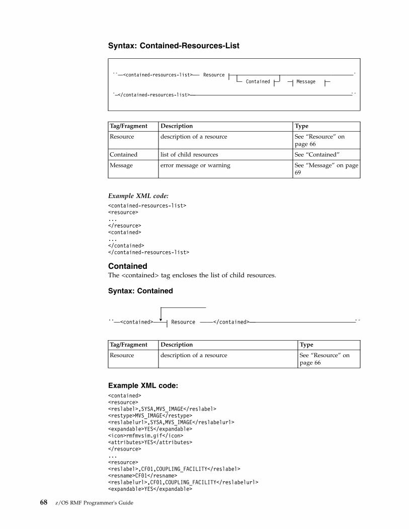
Syntax: Contained-Resources-List
►► <contained-resources-list> ResourceContained Message
►
► </contained-resources-list> ►◄
Tag/Fragment Description Type
Resource description of a resource See “Resource” onpage 66
Contained list of child resources See “Contained”
Message error message or warning See “Message” on page69
Example XML code:<contained-resources-list><resource>...</resource><contained>...</contained></contained-resources-list>
ContainedThe <contained> tag encloses the list of child resources.
Syntax: Contained
►► <contained> ▼ Resource </contained> ►◄
Tag/Fragment Description Type
Resource description of a resource See “Resource” onpage 66
Example XML code:<contained><resource><reslabel>,SYSA,MVS_IMAGE</reslabel><restype>MVS_IMAGE</restype><reslabelurl>,SYSA,MVS_IMAGE</reslabelurl><expandable>YES</expandable><icon>rmfmvsim.gif</icon><attributes>YES</attributes></resource>...<resource><reslabel>,CF01,COUPLING_FACILITY</reslabel><resname>CF01</resname><reslabelurl>,CF01,COUPLING_FACILITY</reslabelurl><expandable>YES</expandable>
68 z/OS RMF Programmer's Guide

<icon>rmfcf.gif</icon><attributes>YES</attributes></resource></contained>
Filter-Instances-List elementThe <filter-instances-list> tag lists all possible filter instances with a specific listtype for the given resource.
Syntax: Filter-Instances-List
►► <filter-instances-list> Resource <listtype> token </listtype> ►
► ▼
<instance> token </instance> Message►
► </filter-instances-list> ►◄
Tag/Fragment Description Type
Resource description of a resource See “Resource” on page66
listtype list type of the requested filter instances token
instance element of the instances list token
Message error message or warning See “Message”
Example XML code:<filter-instances-list><resource>...</resource><listtype>V</listtype><instance>SYSA,IMS610,V</instance>...<instance>SYSA,IMS710,V</instance></filter-instances-list>
MessageThe <message> tag specifies an error message or warning.
Syntax: Message
►► <message id=“token”> <description> token </description> ►
► <severity> byte </severity> </message> ►◄
Tag/Fragment Description Type
id unique message ID token
Chapter 3. Accessing performance data using the RMF Distributed Data Server 69

Tag/Fragment Description Type
description message text token
severity severity of the message byte
Example XML code:<message id="GPM0626I"><description>The metric 008D1000 is not defined for resource type SYSPLEX ...</description><severity>4</severity></message>
Metric-List elementThe <metric-list> tag lists all available metrics for a given resource.
Syntax: Metric-List
►► <metric-list> Resource ▼
Metric Message►
► </metric-list> ►◄
Tag/Fragment Description Type
Resource description of a resource See “Resource” onpage 66
Metric list of metrics for this resource See “Metric”
Message error message or warning See “Message” on page69
Example XML code:<metric-list><resource>...</resource><metric id="8D2060">...</metric>...<metric id="8D1FF0">...</metric></metric-list>
MetricThe <metric> tag describes a metric in detail.
70 z/OS RMF Programmer's Guide

Syntax: Metric
►► <metric id=“token”> ►
► <description> token </description> <format> NMTOKEN </format> ►
►<numcols> nonNegativeInteger </numcols> <listtype> token </listtype>
►
►
▼<workscopes-supported> Workscope-Type </workscopes-supported>
►
►<workscope> token </workscope> <filter> token </filter>
►
►<unit> token </unit> <helpurl> token </helpurl>
►
►<helpid> token </helpid>
</metric> ►◄
Workscope-Type:
<workscope-type> NMTOKEN </workscope-type>
Tag/Fragment Description Type
id unique metric ID token
description description of a metric token
format type of counter used for this metric; value is in{single, list, report}
NMTOKEN
numcols number of columns in report, if metric is a report nonNegativeInteger
listtype list type of the resource token
workscopes-supported
valid workscopes for this metric n/a
workscope-type valid workscope for this metric; value in{G,W,S,P,R,J}
NMTOKEN
workscope description of the workscope (see also “Theworkscope parameter” on page 54)
token
filter filter argument token
unit unit of the values returned by this metric; validvalues in {count, index, megabytes, micro-,milliseconds , percent, rate per hour, rate per second,seconds, undefined}
token
helpurl URL of help document token
helpid ID of corresponding paragraph in help document token
Chapter 3. Accessing performance data using the RMF Distributed Data Server 71

Example XML code:<metric id="8D2060"><description>% processor utilization</description><format>single</format><listtype> </listtype><workscopes-supported><workscope-type>G</workscope-type></workscopes-supported><unit>percent</unit><helpurl>/gpm/include/metrics.html</helpurl><helpid>5050</helpid></metric>
Postprocessor elementThe <postprocessor> tag encloses one Postprocessor report denoted by theMetric-PP specification.
Syntax: Postprocessor
►► <postprocessor> Metric-PP Version-PP Resource-PP ►
► Time-Data-PP ▼
Segment
▼
Message</postprocessor> ►◄
Tag/Fragment Description Type
Metric-PP name of a Postprocessor report See “Metric-PP” onpage 73
Version-PP version information for Postprocessor reports See “Version-PP” onpage 73
Resource-PP description of the reported resource See “Resource-PP”on page 74
Time-Data-PP time information for the report interval See “Time-Data-PP”on page 74
Segment named Postprocessor report segment containingthe report data
See “Segment” onpage 75
Message error message or warning See “Message” onpage 69
Example XML code:<postprocessor><metric id="CPU">...</metric><version>...</version><resource>...</resource><time-data>...</time-data><segment><name>CPU ACTIVITY</name>...</segment><segment><name>PARTITION DATA REPORT</name>...</segment><segment><name>LPAR CLUSTER REPORT</name>...</segment><segment><name>GROUP CAPACITY REPORT</name>...</segment></postprocessor>
72 z/OS RMF Programmer's Guide

Metric-PPThe <metric> tag within the <postprocessor> tag contains the name of aPostprocessor report.
Syntax: Metric-PP
►► <metricid=“token” option=“token”
> ►
► <description> token </description> <type> token </type> ►
►<helpurl> token </helpurl> <helpid> token </helpid>
</metric> ►◄
Tag/Fragment Description Type
id name of the Postprocessor report token
option suboptions specified for the Postprocessor reports token
description descriptive title of the report token
type type of the Postprocessor report; can be eitherInterval, Duration, or Overview
token
helpurl URL of help document token
helpid ID of corresponding paragraph in help document token
Example XML code:<metric id=“CPU”><description>CPU Activity Report</description><type>Interval</type></metric>
Version-PPThe <version> tag within the <postprocessor> tag contains version information forPostprocessor reports.
Syntax: Version
►► <version> <smf_data> token </smf_data> <rmf_report> token </rmf_report> </version> ►◄
Tag/Fragment Description Type
smf_data version of the operating system that captured theSMF data
token
rmf_report version of the RMF Postprocessor token
Example XML code:<version><smf-data>z/OS V1R12</smf-data><rmf-report>V1R12 RMF</rmf-report></version>
Chapter 3. Accessing performance data using the RMF Distributed Data Server 73

Resource-PPA <resource> tag within the <postprocessor> tag specifies the reported resource,for example, a system.
Syntax: Resource-PP
►► <resource> <resname> token </resname> <restype> token </restype> ►
►<helpurl> token </helpurl>
</resource> ►◄
Tag/Fragment Description Type
resname resource name token
restype resource type token
Example XML code:<resource><resname>SYSE</resname><restype>SYSTEM ID</restype></resource>
Time-Data-PPA <time-data> tag within the <postprocessor> tag provides information on thetime intervals used in a report.
Syntax: Time-Data-PP
►► <time-data> <display-start locale=“token”> token </display-start> ►
► <display-end locale=“token”> token </display-end"> ►
► <report-interval unit=“NMTOKEN”> nonNegativeInteger </report-interval> ►
►<cycle unit=“NMTOKEN”> nonNegativeInteger </cycle>
►◄
Tag/Fragment Description Type
display-start local start date and time of the reporting interval indisplayable format mm/dd/yyyy-hh:mm:ss
token
locale locale for which displayable format is shown token
display-end local end date and time of the reporting interval indisplayable format mm/dd/yyyy-hh:mm:ss
token
report-interval length of the measurement interval (reporting time) nonNegativeInteger
cycle cycle length of data sampling nonNegativeInteger
unit unit of time; valid values in {hours, minutes,seconds, milliseconds, microseconds}
NMTOKEN
74 z/OS RMF Programmer's Guide

Example XML code:<time-data><display-start locale="en-us">03/26/2010-11.15.00</display-start><display-end locale="en-us">03/26/2010-11.30.00</display-end><report-interval unit="minutes">14:59:999</report-interval><cycle unit="milliseconds">1000</cycle></time-data>
SegmentA <segment> tag contains one report section (which can consist of multiple parts,in XML terms) of a Postprocessor report.
Syntax: Segment
►► <segmentid=“token”
> <name> token </name> ▼ PartMessage
►
► </segment> ►◄
Tag/Fragment Description Type
id unique segment ID token
name name of a report segment token
Part part of a report segment which can contain anynumber of variable-name/value lists or datatables
See “Part”
Message error message or warning See “Message” onpage 69
Example XML code:<segment><name>CPU ACTIVITY</name><part>...</part><part>...</part>...</segment>
See another <segment> code example in the description of the <table> tag in“Table” on page 77.
PartA <part> tag encloses a part of a report segment. Such a part can either containone or more variable lists (specified by the Var-List fragment) or one or more datatables (specified by the Table fragment).
Syntax: Part
►► <partid=“token”
><name> token </name>
▼ Var-ListTable
►
Chapter 3. Accessing performance data using the RMF Distributed Data Server 75
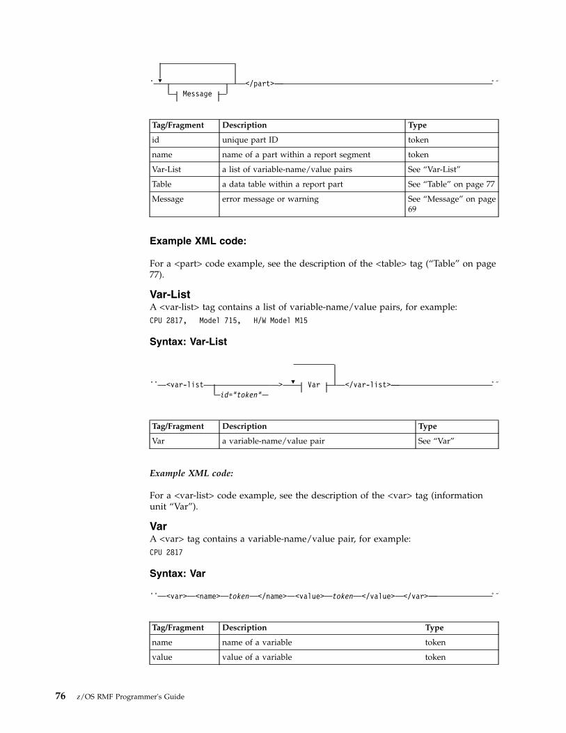
► ▼
Message</part> ►◄
Tag/Fragment Description Type
id unique part ID token
name name of a part within a report segment token
Var-List a list of variable-name/value pairs See “Var-List”
Table a data table within a report part See “Table” on page 77
Message error message or warning See “Message” on page69
Example XML code:
For a <part> code example, see the description of the <table> tag (“Table” on page77).
Var-ListA <var-list> tag contains a list of variable-name/value pairs, for example:CPU 2817, Model 715, H/W Model M15
Syntax: Var-List
►► <var-listid=“token”
> ▼ Var </var-list> ►◄
Tag/Fragment Description Type
Var a variable-name/value pair See “Var”
Example XML code:
For a <var-list> code example, see the description of the <var> tag (informationunit “Var”).
VarA <var> tag contains a variable-name/value pair, for example:CPU 2817
Syntax: Var
►► <var> <name> token </name> <value> token </value> </var> ►◄
Tag/Fragment Description Type
name name of a variable token
value value of a variable token
76 z/OS RMF Programmer's Guide

Example XML code:<segment id="1"><name>CPU Activity</name><part id="2"><var-list id="3"><var><name>CPU</name><value>2817</value></var><var><name>Model</name><value>715</value></var><var><<name>H/W Model</name><value>M15</value></var>...</var-list><table id="4">...</table></part><part id="5">...</part>...</segment>
TableA <table> tag contains a data table, consisting of the column headers and at leastone row.
Syntax: Table
►► <tableid=“token”
><name> token </name>
Column-Headers ►
► ▼ Row </table> ►◄
Tag/Fragment Description Type
id unique table ID token
name name of a table token
Column-Headers unique names of the columns in the reporttable
See “Column-Headers” onpage 81
Row performance data See “Row” on page 81
Example XML code:<segment id="3"><name>Details for all Channels</name><part id="4"><table id="5"><column-headers><col type="T">Channel Path ID</col><col type="T">Type</col><col type="T">Generation</col><col type="T">Shared</col><col type="T">Status</col><col type="N">Util% (LPAR)</col>...</column-headers><row refno="1"><col>0D</col><col>OSD</col><col/><col>Yes</col>
Chapter 3. Accessing performance data using the RMF Distributed Data Server 77

<col>Online</col><col>0.24</col>...</row><row refno="2">...</row></table></part></segment>
Resulting browser display:Details for all Channels
Channel Util%Path ID Type Generation Shared Status (LPAR) ...
0D OSD Yes Online 0.24 ...30 FC_S 9 Yes Online 0.04 ...
Report elementThe <report> tag encloses performance data for a specific resource or metric.
Syntax: Report
►► <report> Metric Resource Time-DataCaption
►
► ▼
Row Column-Headers Message</report> ►◄
Tag/Fragment Description Type
Metric metric used for the report See “Metric” on page 70
Resource description of a resource See “Resource” on page 66
Time-Data time and interval information for the report See “Time-Data” on page79
Caption additional (sub-) headings for the report See “Caption” on page 80
Row performance data See “Row” on page 81
Column-Headers unique names of the columns in the reporttable
See “Column-Headers” onpage 81
Message error message or warning See “Message” on page 69
Example XML code:<report><metric id="CPC">...</metric><resource>...</resource><time-data>...</time-data><caption>...</caption>
78 z/OS RMF Programmer's Guide

<row refno="1">...</row>...<row refno="15">...</row><column-headers>...</column-headers></report>
Time-DataThe <time-data> tag provides information on the time intervals used in a report.
Syntax: Time-Data
►► <time-data> <local-start> token </local-start> ►
► <local-end> token </local-end> <utc-start> token </utc-start> ►
► <utc-end> token </utc-end><local-prev> token </local-prev>
►
►<local-next> token </local-next>
►
► <display-start locale=“token”> token </display-start> ►
► <display-end locale=“token”> token </display-end"> ►
► <gatherer-interval unit=“NMTOKEN”> nonNegativeInteger </gatherer-interval> ►
► <data-range unit=“NMTOKEN”> nonNegativeInteger </data-range> </time-data> ►◄
Tag/Fragment Description Type
local-start local start time of data range in formatyyyymmddhhmmss (a sequence of 14 digits)
token
local-end local end time of data range in formatyyyymmddhhmmss
token
utc-start start of data range, specified as coordinateduniversal time in the format yyyymmddhhmmss
token
utc-end end of range, specified as coordinated universal timein the format yyyymmddhhmmss
token
local-prev local timestamp of previous sample in formatyyyymmddhhmmss
token
local-next local timestamp of next sample in formatyyyymmddhhmmss
token
display-start local start time of data range in displayable formatmm/dd/yyyy hh:mm:ss
token
locale locale for which displayable format is shown token
display-end local end time of data range in displayable formatmm/dd/yyyy hh:mm:ss
token
Chapter 3. Accessing performance data using the RMF Distributed Data Server 79

Tag/Fragment Description Type
gatherer-interval length of gatherer interval nonNegativeInteger
unit unit of time; valid values in {hours, microseconds,milliseconds, minutes, seconds}
NMTOKEN
data-range length of data range nonNegativeInteger
Example XML code:<time-data><local-start>20150214180800</local-start><local-end>20150214180830</local-end><utc-start>20150214170800</utc-start><utc-end>20150214170830</utc-end><local-prev>20150214180745</local-prev><local-next>20150214180845</local-next><display-start locale="en-us">02/14/2015 18:08:00</display-start><display-end locale="en-us">02/14/2015 18:08:30</display-end><gatherer-interval unit="seconds">30</gatherer-interval><data-range unit="seconds">30</data-range></time-data>
CaptionThe <caption> tag contains additional headings and summary information for areport.
Syntax: Caption
►► <caption> ►
► ▼ <var> <name> token </name> <value> token </value> </var> ►
► </caption> ►◄
Tag/Fragment Description Type
var description of variables in additional headings n/a
name name of variable token
value value of variable token
Example XML code:<caption><var><name>CPCHPNAM</name><value>SYSA</value></var>...<var>
80 z/OS RMF Programmer's Guide

<name>CPCHMOD</name><value>2817</value></var></caption>
RowThe <row> tag contains the requested performance data values to be displayed ina Monitor III or Postprocessor report.
Syntax: Row
►► <row refno="nonNegativeInteger"exception=“token”
►
►percent=“token” attributes=“token” type=“token”
> ►
► ▼ <col> token </col> </row> ►◄
Tag/Fragment Description Type
col value for cells in a row of a data table token
refno unique row reference number nonNegativeInteger
exception indicates if the value in this row exceeds exceptionthresholds; valid values in {NONE, WARN, CRIT}
NMTOKEN
percent percentage of the value compared to the maximumvalue in the list (only meaningful for list-valuedmetrics)
token
attributes denotes whether attributes may be queried for theresource in this row; valid values in {YES, NO}
NMTOKEN
type is set if the row contains values with a specialmeaning, for example, SUM denotes a row containinga total of certain previous rows
NMTOKEN
Example XML code of a row in a Postprocessor report:<row refno="1" type="SUM"><col>TOTAL/AVERAGE</col><col>CP</col><col>3.08</col><col>3.05</col><col>191.2</col><col>7.45</col><col>0.58</col></row>
Column-HeadersThe <column-headers> tag contains the names of the columns in the report table:v For Monitor III data, these names are equal to the ISPF variable names in the
Monitor III ISPF reports.
Chapter 3. Accessing performance data using the RMF Distributed Data Server 81

v For Postprocessor data, these names are the field headings in the data tables.
Syntax: Column-Headers
►► <column-headers> ▼ <col > token </col>type=“NMTOKEN”
►
► </column-headers> ►◄
Tag/Fragment Description Type
col unique name of the column token
type data type in this column; valid values in {M, N, S, T}for either Mixed alphanumerics, Numbers, Scalednumbers, or Text
NMTOKEN
Example XML code:<column-headers><col type="T">CPCPPNAM</col><col type="N">CPCPDMSU</col>...<col type="N">CPCPLTOU</col></column-headers>
Workscope-List elementThe <workscope-list> tag lists the available workscopes for a given resource.
Syntax: Workscope-List
►► <workscope-list> Resource ▼
<workscope> token </workscope>►
►Message
</workscope-list> ►◄
Tag/Fragment Description Type
Resource description of a resource See “Resource” on page 66
workscope description of a workscope token
Message error message or warning See “Message” on page 69
Example XML code:<workscope-list><resource>...</resource>
82 z/OS RMF Programmer's Guide

<workscope>,BATCH,W</workscope>...<workscope>,HOTTSO,S</workscope></workscope-list>
RMF-MFP-Message elementThe <rmf-mfpmsg> tag lists the messages which have been generated by RMFPostprocessor and are provided in the MFPMSGDS SYSOUT DD of thePostprocessor job run by the RMF Distributed Data Server.
Syntax: RMF-MFP-Message
►► <rmf-mfpmsg> ▼ <mfpmsg id="token"> token </mfpmsg> </rmf-mfpmsg> ►◄
Tag/Fragment Description Type
mfpmsg message text token
id Postprocessor message ID token
Example XML code:<rmf-mfpmsg>
<mfpmsg id="ERB103I"> PPS: OPTIONS IN EFFECT</mfpmsg><mfpmsg id="ERB103I"> PPS: ETOD(0000,2400) -- DEFAULT</mfpmsg><mfpmsg id="ERB103I"> PPS: NOSUMMARY -- SYSIN</mfpmsg><mfpmsg id="ERB103I"> PPS: REPORTS(CPU) -- SYSIN</mfpmsg><mfpmsg id="ERB103I"> PPS: DATE(01011967,12312066) -- DEFAULT</mfpmsg>
</rmf-mfpmsg>
Coding example for requesting and receiving Monitor IIIperformance data
The subsequent Java™ code sample demonstrates a method how to send a HTTPrequests to the DDS and how to receive the response into a text file, from whereyou can extract the required values.import java.io.*;import java.net.*;import sun.misc.*;
/*************************************************************** A command line program to communicate with the DDS server ***************************************************************/
public class ParseDDS {
public final static String URLPREFIX ="http://<ddshost>:<ddsport>/gpm/";
public final static String OUTFILE = "ParseDDS.txt";
PrintWriter writer;
/**************************************************************************** Constructor: Builds a performance data request and sends it to the DDS. ** Writes results into a local file. ****************************************************************************/
public ParseDDS() {try {
Chapter 3. Accessing performance data using the RMF Distributed Data Server 83
|
|||
|
|||||||||||||||||||||
|
||||
|||
||||
|
|||||||

String urlstr;writer = new PrintWriter(new FileOutputStream(OUTFILE, false));for (int i = 0; i < 1; i++) {
/* Get performance data (Performance index of all service class periods) */
urlstr = URLPREFIX + "perform/perform.xml?resource=,*,SYSPLEX&id=8D1020";getAndWrite(urlstr);
}}catch (Exception e) {
e.printStackTrace();}
writer.close();
}
/********************************************************* Sends request to server and writes XML data to file *********************************************************/
public void getAndWrite(String urlstr) throws Exception {URL url = new URL(urlstr);HttpURLConnection con = (HttpURLConnection) url.openConnection();String line;con.setDoInput(true);con.connect();int cl = con.getContentLength();
/* Write HTTP contents (XML document) to file */
line = "URL=" + urlstr;System.out.println(line);writer.println(line);if (cl > 0) {
BufferedReader reader =new BufferedReader(new InputStreamReader(con.getInputStream()));
int k = 0;while ((line = reader.readLine()) != null) {
k++;System.out.println(line);writer.println(line);
}System.out.println(
" " + cl + " Bytes XML content received from DDS.");}System.out.println(" ");
}
/************************************************************* main *************************************************************/
public static void main(String[] args) {
System.out.println("ParseDDS started. Output will be written to file: " + OUTFILE);
ParseDDS myDDs = new ParseDDS();System.out.println("ParseDDS ended.");System.exit(0);
}}
84 z/OS RMF Programmer's Guide

Chapter 4. z/OS CIM monitoring
The Common Information Model (CIM) is a standard data model developed by aconsortium of major hardware and software vendors (including IBM), called theDistributed Management Task Force (DMTF). It provides a common definition fordescribing and accessing systems management data in heterogeneousenvironments. It allows vendors and system programmers to write applications(CIM monitoring clients) that measure system resources in a network with differentoperating systems and hardware, and to actually manage those systems.
The z/OS base element Common Information Model (z/OS CIM) implements theCIM server, based on the OpenPegasus open source project. A CIM monitoringclient invokes the CIM server, which in turn collects z/OS metrics from the systemand returns it to the calling client.
z/OS CIM Monitoring provides access to z/OS resources and monitoring data.
If a CIM client requests the CIM server to obtain z/OS metrics, the CIM serverinvokes the appropriate z/OS RMF monitoring provider which retrieves thesemetrics associated to z/OS system resources. The z/OS RMF monitoring providersuse RMF Monitor III performance data.
For more information on the z/OS CIM element refer to z/OS Common InformationModel User's Guide.
z/OS RMF CIM monitoringz/OS RMF CIM monitoring for z/OS is available only if RMF is running and theRMF DDS is started. How to provide these prerequisites is described in Startingand stopping RMF, in Setting up the Distributed Data Server, and in Starting theDistributed Data Server in the z/OS RMF User's Guide. How to set the requiredenvironment variables for the CIM server is described in the z/OS CommonInformation Model User's Guide.
z/OS RMF CIM monitoring uses metrics that are associated with resource classesimplemented by the z/OS RMF monitoring providers described in the z/OSCommon Information Model User's Guide.
The following CIM classes have been implemented as IBM supplied providersaccording to the DMTF dynamic metrics model. You can find more informationabout this data model in the CIM Metrics White Paper (DSP0141), which is availableat the DMTF website (www.dmtf.org).v IBMzOS_BaseMetricDefinition: representation of metric definition (for example,
metric name and ID); a subclass of CIM_BaseMetricDefinition
v IBMzOS_BaseMetricValue: representation of a metric value (with value, timestamp and duration); a subclass of CIM_BaseMetricValue
v IBMzOS_MetricDefForME: association between a managed element (resource)and metric definition instances; a subclass of CIM_MetricDefForME.
v IBMzOS_MetricForME: association between a managed element (resource) andmetric value instances; a subclass of CIM_MetricForME.
© Copyright IBM Corp. 1990, 2017 85

v IBMzOS_BaseMetricInstance: association between metric definition and metricvalue instances; a subclass of CIM_MetricInstance.
All instances of IBMzOS_BaseMetricValue will return volatile data. Historical datais not supported with this release.
For a list of the metrics supported in z/OS, see “z/OS metrics” on page 91. Alsosee the CIM class and instance MOF files. The MOF file IBMzOS_Monitoring.mofcan be found in /usr/lpp/wbem/provider/schemas/os_monitoring.
The following diagram illustrates the relationship between the IBM extensionclasses, and the CIM base classes they extend:
Class IBMzOS_OperatingSystem is implemented by the z/OS OS ManagementProviders (part of base element z/OS CIM). It is just an example of a resourcewhich can be inherited from CIM_OperatingSystem. Class CIM_OperatingSystemcan be implemented with the same attributes on any operating system that exploitsthe CIM model. IBMzOS_OperatingSystem inherits all properties from this baseclass and implements further z/OS-specific attributes, like SysplexName and FMID.BaseMetricValue and BaseMetricDefinition instances can be associated to it.
CIM_ManagedElement
CIM_BaseMetricDefinition
IBMzOS_BaseMetricDefinition
IBMzOS_OperatingSystem
IBMzOS_BaseMetricValue
CIM_BaseMetricValue
Caption: stringDescription: stringElementName: string
Name: stringId: stringDataType: uint16Calculable: uint16Units: stringIsContinuous: booleanChangeType: uint16TimeScope: uint16GatheringType: uint16
AssociatedClass: string
SysplexName: stringFMID: string
MetricDefinitionId: stringDuration: datetimeVolatile: booleanBreakdownValue: stringTimeStamp: datetimeMeasuredElementName: stringInstanceId: stringMetricValue: string
Name: stringOSType: uint16Version: stringLastBootUpTime: datetimeLocalDateTime: datetimeCurrentTimeZone: sint16
CIM_OperatingSystem
Shutdown()
Reboot()
+Antecedent
+Antecedent
+Antecedent
+Antecedent +Antecedent
1
CIM_MetricInstance
CIM_MetricInstance
CIM_MetricForMECIM_MetricDefForME
IBM
zOS_
Me
tric
De
fFo
rME
IBM
zOS_
Me
tric
ForM
E
+Dependent +Dependent
+Dependent
+Dependent
+Dependent
+Dependent
+Antecedent
Figure 13. z/OS RMF implementation of the DMTF dynamic metrics model
86 z/OS RMF Programmer's Guide

CIM_BaseMetricDefinition:
An instance of this class represents how a metric is defined. The associated classCIM_BaseMetricValue holds the metric value. CIM_BaseMetricDefinition providesa way to introduce a new metric definition at run time and capture its instancevalues in a separate class.
CIM_BaseMetricValue:
Each instance of this class represents a metric value.
CIM_MetricDefForME/IBMzOS_MetricDefForME:
Traversing this association from a resource returns the set of all metric definitionsfor the given resource. Usage example: If you want to know what metricdefinitions are available for the CIM_Process resource, you can use this association.This association returns static data, which does not change without applyingservice to z/OS CIM. Therefore call it once in your application at startup time tofigure out what is available. You do not need to traverse it several times.
CIM_MetricForME/IBMzOS_MetricForME:
This association links a measured element (resource instance) to all metricinstances available for it. Usage example: Traversing this association starting froman IBMzOS_OperatingSystem instance, returns all associatedIBMzOS_BaseMetricValue instances. In other words, this association returnsmetrics for the z/OS image on which the CIM server is running.
CIM_MetricInstance/IBMzOS_MetricInstance:
Traversing this association gives you all metric instances available for a givenCIM_BaseMetricDefinition. Usage example: In order to get the metric values forthe ResidentSetSize (working set size) of all process instances (z/OS addressspaces) you can start at the metric definition instance of the ResidentSetSizeinstance. Traversing the CIM_MetricInstance association returns all instances of theResidentSetSize metric for all address spaces in your system.
z/OS resource classes based on RMFThis section documents those CIM resource classes available for z/OS that areimplemented based on RMF data.
Note: All described classes are only available if RMF is up and running on thesystem where the monitored resources are located.
Chapter 4. z/OS CIM monitoring 87

IBMz_CECThis resource represents a IBM Z box including processors, memory, I/O cages andso on. Note that CEC (central electronics complex) is a commonly used synonymfor CPC (central processing complex). IBMz_CEC contains the following attributes:
Property Description
string Name (key) CEC serial number
string CreationClassName (key) Value “IBMz_CEC”
string Machine Family Processor type, for example, “2094”
string Machine Type Software model of the processor, for example,“716”
uint32 Capacity System capacity in MSU/hour
uint16 ConfiguredPartitions Number of configured partitions in the CEC
IBMz_ComputerSystemThis class represents a logical partition (LPAR) and contains the followingattributes:
Name : string
CIM_ComputerSystem
LPARName : stringVMGuestID : stringCPUID : stringMachineType : stringModel : stringSerialNumber : string
IBMzOS_ComputerSystem
InitialCappingForCP : uint16InitialCappingForAAP : uint16InitialCappingForIIP : uint16WeightManagement: unit16VaryCPUManagement: unit16zAAPHonorPriority: unit16zIIPHonorPriority: unit16DefinedCapacityGroupName: string
IBMz_ComputerSystem
MachineFamily : stringMachineType : stringCapacity : uint32ConfiguredPartitions : uint16
IBMz_CEC
Based on OS management implementationRepresents a z/OS home partition
Based on RMF management implementationRepresents a System z LPAR
Based on RMF management implementationRepresent a System z box(CEC or CPC)
Figure 14. z/OS resource classes implemented by RMF. Simplified subset of LPAR- and CEC-related resource classes
88 z/OS RMF Programmer's Guide
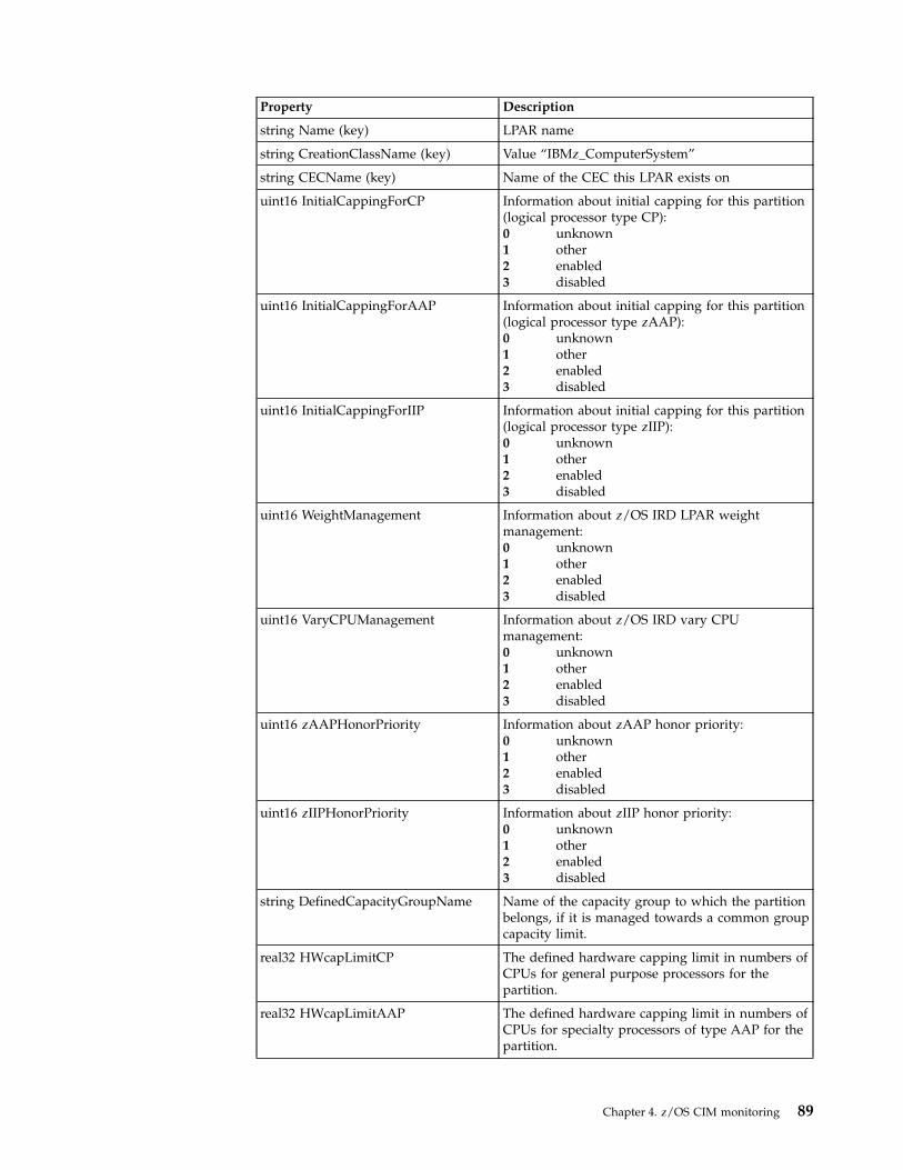
Property Description
string Name (key) LPAR name
string CreationClassName (key) Value “IBMz_ComputerSystem”
string CECName (key) Name of the CEC this LPAR exists on
uint16 InitialCappingForCP Information about initial capping for this partition(logical processor type CP):0 unknown1 other2 enabled3 disabled
uint16 InitialCappingForAAP Information about initial capping for this partition(logical processor type zAAP):0 unknown1 other2 enabled3 disabled
uint16 InitialCappingForIIP Information about initial capping for this partition(logical processor type zIIP):0 unknown1 other2 enabled3 disabled
uint16 WeightManagement Information about z/OS IRD LPAR weightmanagement:0 unknown1 other2 enabled3 disabled
uint16 VaryCPUManagement Information about z/OS IRD vary CPUmanagement:0 unknown1 other2 enabled3 disabled
uint16 zAAPHonorPriority Information about zAAP honor priority:0 unknown1 other2 enabled3 disabled
uint16 zIIPHonorPriority Information about zIIP honor priority:0 unknown1 other2 enabled3 disabled
string DefinedCapacityGroupName Name of the capacity group to which the partitionbelongs, if it is managed towards a common groupcapacity limit.
real32 HWcapLimitCP The defined hardware capping limit in numbers ofCPUs for general purpose processors for thepartition.
real32 HWcapLimitAAP The defined hardware capping limit in numbers ofCPUs for specialty processors of type AAP for thepartition.
Chapter 4. z/OS CIM monitoring 89
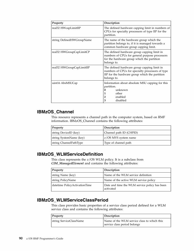
Property Description
real32 HWcapLimitIIP The defined hardware capping limit in numbers ofCPUs for specialty processors of type IIP for thepartition.
string DefinedHWGroupName The name of the hardware group which thepartition belongs to, if it is managed towards acommon hardware group capping limit.
real32 HWGroupCapLimitCP The defined hardware group capping limit innumbers of CPUs for general purpose processorsfor the hardware group which the partitionbelongs to.
real32 HWGroupCapLimitIIP The defined hardware group capping limit innumbers of CPUs for specialty processors of typeIIP for the hardware group which the partitionbelongs to.
uint16 AbsMSUCap Information about absolute MSU capping for thispartition.0 unknown1 other2 enabled3 disabled
IBMzOS_ChannelThis resource represents a channel path in the computer system, based on RMFinformation. IBMzOS_Channel contains the following attributes:
Property Description
string DeviceID (key) Channel path ID (CHPID)
string SystemName (key) z/OS MVS system name
string ChannelPathType Type of channel path
IBMzOS_WLMServiceDefinitionThis class represents the z/OS WLM policy. It is a subclass fromCIM_ManagedElement and contains the following attributes:
Property Description
string Name (key) Name of the WLM service definition
string PolicyName Name of the active WLM service policy
datetime PolicyActivationTime Date and time the WLM service policy has beenactivated
IBMzOS_WLMServiceClassPeriodThis class provides basic properties of a service class period defined for a WLMservice class and contains the following attributes:
Property Description
string ServiceClassName Name of the WLM service class to which thisservice class period belongs
90 z/OS RMF Programmer's Guide

Property Description
string PeriodNumber Service class period in which the service class iscurrently running
uint16 ImportanceLevel Importance level ranging form 1 to 5 where 1 isthe most important level. If the property valuecannot be determined, for example, for inactiveservice classes periods or for service class periodswith importance ‘discretionary’, NULL is returned.
z/OS metricsThis chapter describes the CIM metrics, as they are supported by z/OS RMF, withz/OS specific details.
In the following, this chapter contains a subsection for each resource class whichlists the metrics available for these classes.
IBMzOS_LogicalDiskThis class represents a logical disk in the system. The following metrics areassociated to IBMzOS_LogicalDisk:
Property type Property value Property type Property value
ActiveTimePercentage
Description: Percentage of time the disk unit was actively processing requests, calculatedas the sum of connect, disconnect and pending time.
This metric cannot exceed 100%, and it does not state how many requests were active atany given time.
Datatype real32 Units percent
ChangeType 4 (Gauge) TimeScope 3 (Interval)
GatheringType 3 (Periodic) IsContinuous true
DDS metricname
% active time DDS metric ID 8D0010
Associatedclass
IBMzOS_LogicalDisk
AvailableSpace
Description: Free capacity on the disk drive.
Datatype uint64 Units bytes
ChangeType 4 (Gauge) TimeScope 2 (Point)
GatheringType 3 (Periodic) IsContinuous true
DDS metricname
freespace DDS metric ID 8D3090
Associatedclass
IBMzOS_LogicalDisk
AverageDeviceUtilization
Chapter 4. z/OS CIM monitoring 91

Property type Property value Property type Property value
Description: Average device utilization (not normalized to 100% for parallel I/O activity).
This metric can be above 100% if the device is executing multiple I/Os in parallel. A busytime percentage of 200% means that on average, the device was executing two I/Os inparallel. This metric does not tell you whether the busy time of the measured device couldbe even higher, because this is architecture dependent.
Datatype real32 Units percent
ChangeType 4 (Gauge) TimeScope 3 (Interval)
GatheringType 3 (Periodic) IsContinuous true
DDS metricname
i/o activity rate and responsetime
DDS metric ID based on 8D0E90 and8D10F0
Associatedclass
IBMzOS_LogicalDisk
Capacity
Description: Capacity of the disk drive.
Datatype uint64 Units bytes
ChangeType 4 (Gauge) TimeScope 2 (Point)
GatheringType 3 (Periodic) IsContinuous true
DDS metricname
capacity DDS metric ID 8D2FF0
Associatedclass
IBMzOS_LogicalDisk
FastWriteRate
Description: Rate of write operations executed as fast writes.
Datatype real32 Units 1/s
ChangeType 4 (Gauge) TimeScope 3 (Interval)
GatheringType 3 (Periodic) IsContinuous true
DDS metricname
cache DFW hits (all systems) DDS metric ID 8D21D0
Associatedclass
IBMzOS_LogicalDisk
IOIntensity
Description: I/O utilization indicator: IOIntensity = ResponseTime * IORate
Datatype real32 Units milliseconds per second
ChangeType 4 (Gauge) TimeScope 3 (Interval)
GatheringType 3 (Periodic) IsContinuous true
DDS metricname
i/o intensity DDS metric ID 8D1290
Associatedclass
IBMzOS_LogicalDisk
QueueDepth
Description: Average number of I/O requests currently in queue (OS view).
Datatype real32 Units s/s = I/O request rate[1/s] * average responsetime [ms] / 1000
92 z/OS RMF Programmer's Guide

Property type Property value Property type Property value
ChangeType 4 (Gauge) TimeScope 3 (Interval)
GatheringType 3 (Periodic) IsContinuous true
DDS metricname
i/o activity rate and responsetime
DDS metric ID based on 8D0E90 and8D10F0
Associatedclass
IBMzOS_LogicalDisk
ReadCacheHitRate
Description: Rate of read requests that did not need access to disk drives because data wasavailable in cache.
Datatype real32 Units 1/s
ChangeType 4 (Gauge) TimeScope 3 (Interval)
GatheringType 3 (Periodic) IsContinuous true
DDS metricname
cache read hits (all systems) DDS metric ID 8D2280
Associatedclass
IBMzOS_LogicalDisk
RequestRate
Description: Number of I/O requests per second for the associated device.
Datatype real32 Units 1 / s (events per second)
ChangeType 4 (Gauge) TimeScope 3 (Interval)
GatheringType 3 (Periodic) IsContinuous true
DDS metricname
i/o activity rate DDS metric ID 8D0E90
Associatedclass
IBMzOS_LogicalDisk
ResponseTime
Description: ResponseTime associated to a logical disk drive. The average response time(in milliseconds) that the device required to complete an I/O request. For comparison ofaverage response times on different platforms, please keep in mind that this metric may bereported by the disk device itself or it may be computed by the operating system,beginning at the point in time when an application issues a disk related command andending at the point in time when the data is returned. In this case, the queue times,network times and other components of response time are included in the ResponseTimemetric.
In z/OS, this metric represents the operating system view of the disk response time.
Datatype real32 Units milliseconds
ChangeType 4 (Gauge) TimeScope 3 (Interval)
GatheringType 3 (Periodic) IsContinuous true
DDS metricname
response time DDS metric ID 8D10F0
Associatedclass
IBMzOS_LogicalDisk
WaitTime
Chapter 4. z/OS CIM monitoring 93

Property type Property value Property type Property value
Description: WaitTime associated to a logical disk drive.
This metric comprises an estimation of the delay components of ResponseTime (inmilliseconds), or AverageResponseTime minus service time, and the time spent in queues.
Datatype real32 Units milliseconds
ChangeType 4 (Gauge) TimeScope 3 (Interval)
GatheringType 3 (Periodic) IsContinuous true
DDS metricname
% connect time and responsetime
DDS metric ID based on 8D00B0 and8D10F0
Associatedclass
IBMzOS_LogicalDisk
IBMz_CECThis class contains basic properties of a CEC box of a IBM Z.
Note: Not only that CEC is instrumented on which RMF is running, but all CECsof the sysplex. If z/OS is running as a guest under z/VM, IBMz_CEC instancesand associated metrics are not available.
Property type Property value Property type Property value
LPARWeightForAAP
Description: LPAR weight for processor type zAAP.
Datatype uint32 Units weight
ChangeType 4 (Gauge) TimeScope 2 (Point)
GatheringType 3 (Periodic) IsContinuous true
DDS metricname
LPAR weight (AAP) DDS metric ID 8D3F30
Associatedclass
IBMz_CEC
LPARWeightForCP
Description: LPAR weight for standard processor.
Datatype uint32 Units weight
ChangeType 4 (Gauge) TimeScope 2 (Point)
GatheringType 3 (Periodic) IsContinuous true
DDS metricname
LPAR weight (CP) DDS metric ID 8D3F60
Associatedclass
IBMz_CEC
LPARWeightForICF
Description: LPAR weight for processor type ICF.
Datatype uint32 Units weight
ChangeType 4 (Gauge) TimeScope 2 (Point)
GatheringType 3 (Periodic) IsContinuous true
DDS metricname
LPAR weight (ICF) DDS metric ID 8D3F90
94 z/OS RMF Programmer's Guide

Property type Property value Property type Property value
Associatedclass
IBMz_CEC
LPARWeightForIFL
Description: LPAR weight for processor type IFL.
Datatype uint32 Units weight
ChangeType 4 (Gauge) TimeScope 2 (Point)
GatheringType 3 (Periodic) IsContinuous true
DDS metricname
LPAR weight (IFL) DDS metric ID 8D3FE0
Associatedclass
IBMz_CEC
LPARWeightForIIP
Description: LPAR weight for processor type zIIP.
Datatype uint32 Units weight
ChangeType 4 (Gauge) TimeScope 2 (Point)
GatheringType 3 (Periodic) IsContinuous true
DDS metricname
LPAR weight (IIP) DDS metric ID 8D4010
Associatedclass
IBMz_CEC
NumberOfDedicatedCPs
Description: Number of dedicated standard processors.
Datatype uint32 Units processors
ChangeType 4 (Gauge) TimeScope 2 (Point)
GatheringType 3 (Periodic) IsContinuous true
DDS metricname
none DDS metric ID none
Associatedclass
IBMz_CEC
NumberOfDefinedAAPs
Description: Number of defined processors of type zAAP.
Datatype uint32 Units processors
ChangeType 4 (Gauge) TimeScope 2 (Point)
GatheringType 3 (Periodic) IsContinuous true
DDS metricname
none DDS metric ID none
Associatedclass
IBMz_CEC
NumberOfDefinedCPs
Description: Number of defined standard processors.
Datatype uint32 Units processors
ChangeType 4 (Gauge) TimeScope 2 (Point)
GatheringType 3 (Periodic) IsContinuous true
Chapter 4. z/OS CIM monitoring 95

Property type Property value Property type Property value
DDS metricname
none DDS metric ID none
Associatedclass
IBMz_CEC
NumberOfDefinedICFs
Description: Number of defined processors of type ICF.
Datatype uint32 Units processors
ChangeType 4 (Gauge) TimeScope 2 (Point)
GatheringType 3 (Periodic) IsContinuous true
DDS metricname
none DDS metric ID none
Associatedclass
IBMz_CEC
NumberOfDefinedIFLs
Description: Number of defined processors of type IFL.
Datatype uint32 Units processors
ChangeType 4 (Gauge) TimeScope 2 (Point)
GatheringType 3 (Periodic) IsContinuous true
DDS metricname
none DDS metric ID none
Associatedclass
IBMz_CEC
NumberOfDefinedIIPs
Description: Number of defined processors of type zIIP.
Datatype uint32 Units processors
ChangeType 4 (Gauge) TimeScope 2 (Point)
GatheringType 3 (Periodic) IsContinuous true
DDS metricname
none DDS metric ID none
Associatedclass
IBMz_CEC
NumberOfSharedAAPs
Description: Number of shared processors of type zAAP.
Datatype real32 Units processors
ChangeType 4 (Gauge) TimeScope 3 (Interval)
GatheringType 3 (Periodic) IsContinuous true
DDS metricname
none DDS metric ID none
Associatedclass
IBMz_CEC
NumberOfSharedCPs
Description: Number of shared standard processors.
Datatype uint32 Units processors
ChangeType 4 (Gauge) TimeScope 2 (Point)
96 z/OS RMF Programmer's Guide

Property type Property value Property type Property value
GatheringType 3 (Periodic) IsContinuous true
DDS metricname
none DDS metric ID none
Associatedclass
IBMz_CEC
NumberOfSharedIIPs
Description: Number of zIIPs in zIIP shared pool (shared physicals).
Datatype uint32 Units processors
ChangeType 4 (Gauge) TimeScope 2 (Point)
GatheringType 3 (Periodic) IsContinuous true
DDS metricname
none DDS metric ID none
Associatedclass
IBMz_CEC
SumOfAAPsAcrossLPARs
Description: Sum of shared logical zAAP processors or cores across all LPARs in CEC.
Datatype uint32 Units processors
ChangeType 4 (Gauge) TimeScope 2 (Point)
GatheringType 3 (Periodic) IsContinuous true
DDS metricname
# logical processors shared(AAP)
DDS metric ID 8D3B70
Associatedclass
IBMz_CEC
SumOfCPsAcrossLPARs
Description: Sum of CPs across all LPARs in CEC (shared logicals).
Datatype uint32 Units processors
ChangeType 4 (Gauge) TimeScope 2 (Point)
GatheringType 3 (Periodic) IsContinuous true
DDS metricname
# logical processors shared (CP) DDS metric ID 8D3BA0
Associatedclass
IBMz_CEC
SumOfIIPsAcrossLPARs
Description: Sum of shared logical zIIP processors or cores across all LPARs in CEC.
Datatype uint32 Units processors
ChangeType 4 (Gauge) TimeScope 2 (Point)
GatheringType 3 (Periodic) IsContinuous true
DDS metricname
# logical processors shared (IIP) DDS metric ID 8D3C50
Associatedclass
IBMz_CEC
SumOfOnlineAAPsAcrossLPARs
Description: Sum of online logical zAAP processors or cores across all LPARs in CEC.
Datatype uint32 Units processors
Chapter 4. z/OS CIM monitoring 97

Property type Property value Property type Property value
ChangeType 4 (Gauge) TimeScope 2 (Point)
GatheringType 3 (Periodic) IsContinuous true
DDS metricname
# processors online (AAP) DDS metric ID 8D3C80
Associatedclass
IBMz_CEC
SumOfOnlineCPsAcrossLPARs
Description: Sum of online CPs across all LPARs in CEC (shared logicals).
Datatype uint32 Units processors
ChangeType 4 (Gauge) TimeScope 2 (Point)
GatheringType 3 (Periodic) IsContinuous true
DDS metricname
# processors online (CP) DDS metric ID 8D3CA0
Associatedclass
IBMz_CEC
SumOfOnlineIIPsAcrossLPARs
Description: Sum of online logical zIIP processors or cores across all LPARs in CEC.
Datatype uint32 Units processors
ChangeType 4 (Gauge) TimeScope 2 (Point)
GatheringType 3 (Periodic) IsContinuous true
DDS metricname
# processors online (IIP) DDS metric ID 8D3D50
Associatedclass
IBMz_CEC
TotalAAPTimePercentage
Description: Total physical zAAP utilization percentage (CEC level).
Datatype real32 Units percent
ChangeType 4 (Gauge) TimeScope 3 (Interval)
GatheringType 3 (Periodic) IsContinuous true
DDS metricname
% of total physical utilization(AAP)
DDS metric ID 8D3300
Associatedclass
IBMz_CEC
TotalCPTimePercentage
Description: Total physical CP utilization percentage (CEC level).
Datatype real32 Units percent
ChangeType 4 (Gauge) TimeScope 3 (Interval)
GatheringType 3 (Periodic) IsContinuous true
DDS metricname
% of total physical utilization(CP)
DDS metric ID 8D2540
Associatedclass
IBMz_CEC
TotalIIPTimePercentage
Description: Total physical zIIP utilization percentage (CEC level).
98 z/OS RMF Programmer's Guide
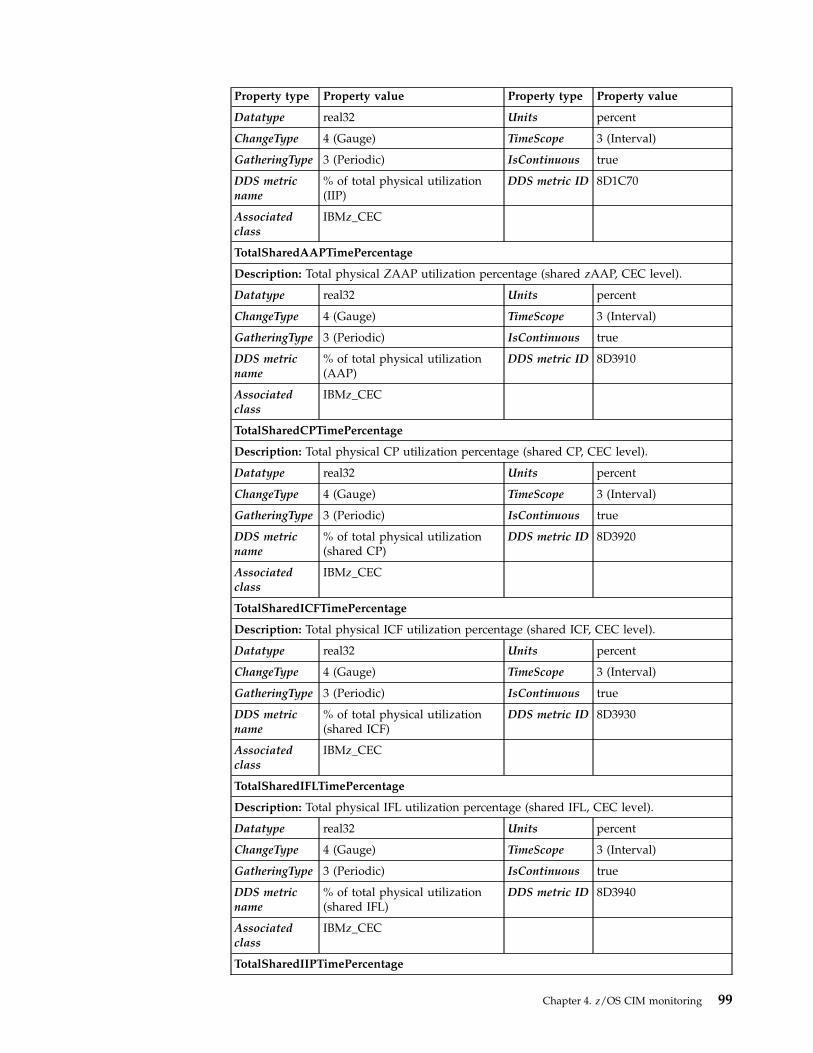
Property type Property value Property type Property value
Datatype real32 Units percent
ChangeType 4 (Gauge) TimeScope 3 (Interval)
GatheringType 3 (Periodic) IsContinuous true
DDS metricname
% of total physical utilization(IIP)
DDS metric ID 8D1C70
Associatedclass
IBMz_CEC
TotalSharedAAPTimePercentage
Description: Total physical ZAAP utilization percentage (shared zAAP, CEC level).
Datatype real32 Units percent
ChangeType 4 (Gauge) TimeScope 3 (Interval)
GatheringType 3 (Periodic) IsContinuous true
DDS metricname
% of total physical utilization(AAP)
DDS metric ID 8D3910
Associatedclass
IBMz_CEC
TotalSharedCPTimePercentage
Description: Total physical CP utilization percentage (shared CP, CEC level).
Datatype real32 Units percent
ChangeType 4 (Gauge) TimeScope 3 (Interval)
GatheringType 3 (Periodic) IsContinuous true
DDS metricname
% of total physical utilization(shared CP)
DDS metric ID 8D3920
Associatedclass
IBMz_CEC
TotalSharedICFTimePercentage
Description: Total physical ICF utilization percentage (shared ICF, CEC level).
Datatype real32 Units percent
ChangeType 4 (Gauge) TimeScope 3 (Interval)
GatheringType 3 (Periodic) IsContinuous true
DDS metricname
% of total physical utilization(shared ICF)
DDS metric ID 8D3930
Associatedclass
IBMz_CEC
TotalSharedIFLTimePercentage
Description: Total physical IFL utilization percentage (shared IFL, CEC level).
Datatype real32 Units percent
ChangeType 4 (Gauge) TimeScope 3 (Interval)
GatheringType 3 (Periodic) IsContinuous true
DDS metricname
% of total physical utilization(shared IFL)
DDS metric ID 8D3940
Associatedclass
IBMz_CEC
TotalSharedIIPTimePercentage
Chapter 4. z/OS CIM monitoring 99
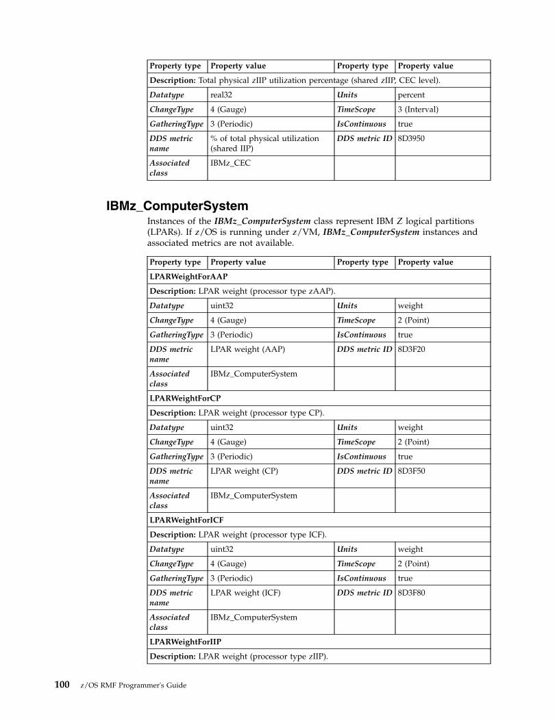
Property type Property value Property type Property value
Description: Total physical zIIP utilization percentage (shared zIIP, CEC level).
Datatype real32 Units percent
ChangeType 4 (Gauge) TimeScope 3 (Interval)
GatheringType 3 (Periodic) IsContinuous true
DDS metricname
% of total physical utilization(shared IIP)
DDS metric ID 8D3950
Associatedclass
IBMz_CEC
IBMz_ComputerSystemInstances of the IBMz_ComputerSystem class represent IBM Z logical partitions(LPARs). If z/OS is running under z/VM, IBMz_ComputerSystem instances andassociated metrics are not available.
Property type Property value Property type Property value
LPARWeightForAAP
Description: LPAR weight (processor type zAAP).
Datatype uint32 Units weight
ChangeType 4 (Gauge) TimeScope 2 (Point)
GatheringType 3 (Periodic) IsContinuous true
DDS metricname
LPAR weight (AAP) DDS metric ID 8D3F20
Associatedclass
IBMz_ComputerSystem
LPARWeightForCP
Description: LPAR weight (processor type CP).
Datatype uint32 Units weight
ChangeType 4 (Gauge) TimeScope 2 (Point)
GatheringType 3 (Periodic) IsContinuous true
DDS metricname
LPAR weight (CP) DDS metric ID 8D3F50
Associatedclass
IBMz_ComputerSystem
LPARWeightForICF
Description: LPAR weight (processor type ICF).
Datatype uint32 Units weight
ChangeType 4 (Gauge) TimeScope 2 (Point)
GatheringType 3 (Periodic) IsContinuous true
DDS metricname
LPAR weight (ICF) DDS metric ID 8D3F80
Associatedclass
IBMz_ComputerSystem
LPARWeightForIIP
Description: LPAR weight (processor type zIIP).
100 z/OS RMF Programmer's Guide

Property type Property value Property type Property value
Datatype uint32 Units weight
ChangeType 4 (Gauge) TimeScope 2 (Point)
GatheringType 3 (Periodic) IsContinuous true
DDS metricname
LPAR weight (IIP) DDS metric ID 8D4000
Associatedclass
IBMz_ComputerSystem
MTCapFactorCP
Description: MT capacity factor for CP
Datatype real64 Units MT capacity factor
ChangeType 4 (Gauge) TimeScope 3 (Interval)
GatheringType 3 (Periodic) IsContinuous true
DDS metricname
MT capacity factor for CP DDS metric ID 8D4B10
Associatedclass
IBMz_ComputerSystem
MTCapFactorIIP
Description: MT capacity factor for IIP
Datatype real64 Units MT capacity factor
ChangeType 4 (Gauge) TimeScope 3 (Interval)
GatheringType 3 (Periodic) IsContinuous true
DDS metricname
MT capacity factor for IIP DDS metric ID 8D4B30
Associatedclass
IBMz_ComputerSystem
MTMaxCapFactorCP
Description: MT maximum capacity factor for CP
Datatype real64 Units MT capacity factor
ChangeType 4 (Gauge) TimeScope 3 (Interval)
GatheringType 3 (Periodic) IsContinuous true
DDS metricname
MT maximum capacity factorfor CP
DDS metric ID 8D4B70
Associatedclass
IBMz_ComputerSystem
MTMaxCapFactorIIP
Description: MT maximum capacity factor for IIP
Datatype real64 Units MT capacity factor
ChangeType 4 (Gauge) TimeScope 3 (Interval)
GatheringType 3 (Periodic) IsContinuous true
DDS metricname
MT maximum capacity factorfor IIP
DDS metric ID 8D4B90
Associatedclass
IBMz_ComputerSystem
MTModeCP
Chapter 4. z/OS CIM monitoring 101

Property type Property value Property type Property value
Description: MT mode for processor type CP
Datatype uint16 Units MT mode
ChangeType 4 (Gauge) TimeScope 2 (Point)
GatheringType 3 (Periodic) IsContinuous true
DDS metricname
MT mode for CP DDS metric ID 8D4BD0
Associatedclass
IBMz_ComputerSystem
MTModeIIP
Description: MT mode for processor type IIP
Datatype uint16 Units MT mode
ChangeType 4 (Gauge) TimeScope 2 (Point)
GatheringType 3 (Periodic) IsContinuous true
DDS metricname
MT mode for IIP DDS metric ID 8D4BF0
Associatedclass
IBMz_ComputerSystem
NumberOfDedicatedAAPs
Description: Number of dedicated processors or cores of type zAAP.
Datatype real32 Units processors
ChangeType 4 (Gauge) TimeScope 3 (Interval)
GatheringType 3 (Periodic) IsContinuous true
DDS metricname
# processors dedicated (AAP) DDS metric ID 8D3B00
Associatedclass
IBMz_ComputerSystem
NumberOfDedicatedCPs
Description: Number of dedicated standard processors.
Datatype real32 Units processors
ChangeType 4 (Gauge) TimeScope 3 (Interval)
GatheringType 3 (Periodic) IsContinuous true
DDS metricname
# processors dedicated (CP) DDS metric ID 8D3B20
Associatedclass
IBMz_ComputerSystem
NumberOfDedicatedIIPs
Description: Number of dedicated processors or cores of type zIIP.
Datatype real32 Units processors
ChangeType 4 (Gauge) TimeScope 3 (Interval)
GatheringType 3 (Periodic) IsContinuous true
DDS metricname
# processors dedicated (IIP) DDS metric ID 8D3B40
Associatedclass
IBMz_ComputerSystem
102 z/OS RMF Programmer's Guide

Property type Property value Property type Property value
NumberOfOnlineAAPs
Description: Number of online processors or cores of type zAAP.
Datatype real32 Units processors
ChangeType 4 (Gauge) TimeScope 3 (Interval)
GatheringType 3 (Periodic) IsContinuous true
DDS metricname
# processors online (AAP) DDS metric ID 8D3C70
Associatedclass
IBMz_ComputerSystem
NumberOfOnlineCPs
Description: Number of online standard processors.
Datatype real32 Units processors
ChangeType 4 (Gauge) TimeScope 3 (Interval)
GatheringType 3 (Periodic) IsContinuous true
DDS metricname
# processors online (CP) DDS metric ID 8D2610
Associatedclass
IBMz_ComputerSystem
NumberOfOnlineICFs
Description: Number of online processors of type ICF.
Datatype real32 Units processors
ChangeType 4 (Gauge) TimeScope 3 (Interval)
GatheringType 3 (Periodic) IsContinuous true
DDS metricname
# processors online (ICF) DDS metric ID 8D3CC0
Associatedclass
IBMz_ComputerSystem
NumberOfOnlineIFLs
Description: Number of online processors of type IFL.
Datatype real32 Units processors
ChangeType 4 (Gauge) TimeScope 3 (Interval)
GatheringType 3 (Periodic) IsContinuous true
DDS metricname
# processors online (IFL) DDS metric ID 8D3D10
Associatedclass
IBMz_ComputerSystem
NumberOfOnlineIIPs
Description: Number of online processors or cores of type zIIP.
Datatype real32 Units processors
ChangeType 4 (Gauge) TimeScope 3 (Interval)
GatheringType 3 (Periodic) IsContinuous true
DDS metricname
# processors online (IIP) DDS metric ID 8D3D40
Chapter 4. z/OS CIM monitoring 103

Property type Property value Property type Property value
Associatedclass
IBMz_ComputerSystem
NumberOfSharedAAPs
Description: Number of shared processors or cores of type zAAP.
Datatype real32 Units processors
ChangeType 4 (Gauge) TimeScope 3 (Interval)
GatheringType 3 (Periodic) IsContinuous true
DDS metricname
# logical processors shared(AAP)
DDS metric ID 8D3B60
Associatedclass
IBMz_ComputerSystem
NumberOfSharedCPs
Description: Number of shared standard processors (shared logicals).
Datatype real32 Units processors
ChangeType 4 (Gauge) TimeScope 3 (Interval)
GatheringType 3 (Periodic) IsContinuous true
DDS metricname
# logical processors shared (CP) DDS metric ID 8D3B90
Associatedclass
IBMz_ComputerSystem
NumberOfSharedIIPs
Description: Number of shared processors or cores of type zIIP.
Datatype real32 Units processors
ChangeType 4 (Gauge) TimeScope 3 (Interval)
GatheringType 3 (Periodic) IsContinuous true
DDS metricname
# logical processors shared (IIP) DDS metric ID 8D3C40
Associatedclass
IBMz_ComputerSystem
PartitionCapacityCappedPercentage
Description: WLM capping percentage.
Datatype real32 Units percent
ChangeType 4 (Gauge) TimeScope 3 (Interval)
GatheringType 3 (Periodic) IsContinuous true
DDS metricname
% WLM capping DDS metric ID 8D2490
Associatedclass
IBMz_ComputerSystem
PartitionCapacityFourHourAverage
Description: Four hour rolling average.
Datatype uint64 Units MSU/h
ChangeType 4 (Gauge) TimeScope 3 (Interval)
GatheringType 3 (Periodic) IsContinuous true
104 z/OS RMF Programmer's Guide

Property type Property value Property type Property value
DDS metricname
four hour MSU average DDS metric ID 8D2630
Associatedclass
IBMz_ComputerSystem
PartitionDefinedCapacity
Description: Percentage of defined CPU capacity used by this LPAR or VM guest.
Datatype real32 Units percent
ChangeType 4 (Gauge) TimeScope 3 (Interval)
GatheringType 3 (Periodic) IsContinuous true
DDS metricname
defined MSU DDS metric ID 8D2620
Associatedclass
IBMzOS_ComputerSystem
PartitionDefinedCapacityUsedPercentage
Description: Percentage of defined CPU capacity used by this LPAR or z/VM guest.
Datatype real32 Units percent
ChangeType 4 (Gauge) TimeScope 3 (Interval)
GatheringType 3 (Periodic) IsContinuous true
DDS metricname
% capacity used DDS metric ID 8D2870
Associatedclass
IBMzOS_ComputerSystem
TotalAAPTimePercentage
Description: zAAP time percentage.
Datatype real32 Units percent
ChangeType 4 (Gauge) TimeScope 3 (Interval)
GatheringType 3 (Periodic) IsContinuous true
DDS metricname
% total logical utilization (AAP) DDS metric ID 8D38D0
Associatedclass
IBMz_ComputerSystem
TotalAAPonCPTimePercentage
Description: zAAP on CP time percentage.
Datatype real32 Units percent
ChangeType 4 (Gauge) TimeScope 3 (Interval)
GatheringType 3 (Periodic) IsContinuous true
DDS metricname
% AAP on CP DDS metric ID 8D2C90
Associatedclass
IBMz_ComputerSystem
TotalCPTimePercentage
Description: Total CP time percentage.
Datatype real32 Units percent
ChangeType 4 (Gauge) TimeScope 3 (Interval)
Chapter 4. z/OS CIM monitoring 105

Property type Property value Property type Property value
GatheringType 3 (Periodic) IsContinuous true
DDS metricname
% total logical utilization (CP) DDS metric ID 8D2510
Associatedclass
IBMz_ComputerSystem
TotalIIPonCPTimePercentage
Description: zIIP on CP time percentage.
Datatype real32 Units percent
ChangeType 4 (Gauge) TimeScope 3 (Interval)
GatheringType 3 (Periodic) IsContinuous true
DDS metricname
% IIP on CP DDS metric ID 8D3550
Associatedclass
IBMz_ComputerSystem
TotalIIPTimePercentage
Description: Total zIIP time percentage.
Datatype real32 Units percent
ChangeType 4 (Gauge) TimeScope 3 (Interval)
GatheringType 3 (Periodic) IsContinuous true
DDS metricname
% total logical utilization (IIP) DDS metric ID 8D3900
Associatedclass
IBMz_ComputerSystem
RemainingTimeUntilCapping
Description: Remaining time until capping in seconds.
Datatype unit64 Units seconds
ChangeType 4 (Gauge) TimeScope 3 (Interval)
GatheringType 3 (Periodic) IsContinuous true
DDS metricname
remaining time until capping inseconds
DDS metric ID 8D2680
Associatedclass
IBMz_ComputerSystem
RemainingTimeUntilGroupCapping
Description: Remaining time until group capping in seconds.
Datatype unit64 Units seconds
ChangeType 4 (Gauge) TimeScope 3 (Interval)
GatheringType 3 (Periodic) IsContinuous true
DDS metricname
remaining time until groupcapping in seconds
DDS metric ID 8D4460
Associatedclass
IBMz_ComputerSystem
AvailableCapacityForCapacityGroup
Description: available capacity (MSU/h) for the group.
Datatype unit64 Units MSU/h
106 z/OS RMF Programmer's Guide
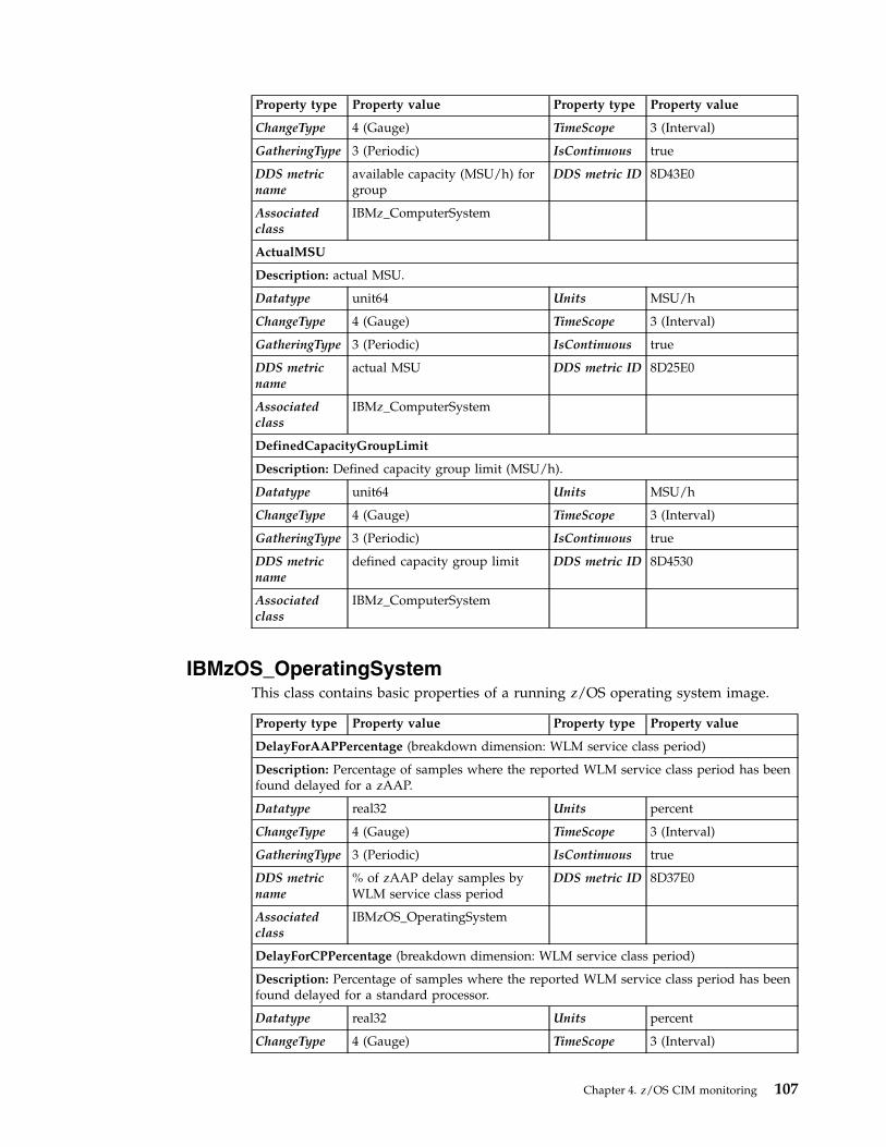
Property type Property value Property type Property value
ChangeType 4 (Gauge) TimeScope 3 (Interval)
GatheringType 3 (Periodic) IsContinuous true
DDS metricname
available capacity (MSU/h) forgroup
DDS metric ID 8D43E0
Associatedclass
IBMz_ComputerSystem
ActualMSU
Description: actual MSU.
Datatype unit64 Units MSU/h
ChangeType 4 (Gauge) TimeScope 3 (Interval)
GatheringType 3 (Periodic) IsContinuous true
DDS metricname
actual MSU DDS metric ID 8D25E0
Associatedclass
IBMz_ComputerSystem
DefinedCapacityGroupLimit
Description: Defined capacity group limit (MSU/h).
Datatype unit64 Units MSU/h
ChangeType 4 (Gauge) TimeScope 3 (Interval)
GatheringType 3 (Periodic) IsContinuous true
DDS metricname
defined capacity group limit DDS metric ID 8D4530
Associatedclass
IBMz_ComputerSystem
IBMzOS_OperatingSystemThis class contains basic properties of a running z/OS operating system image.
Property type Property value Property type Property value
DelayForAAPPercentage (breakdown dimension: WLM service class period)
Description: Percentage of samples where the reported WLM service class period has beenfound delayed for a zAAP.
Datatype real32 Units percent
ChangeType 4 (Gauge) TimeScope 3 (Interval)
GatheringType 3 (Periodic) IsContinuous true
DDS metricname
% of zAAP delay samples byWLM service class period
DDS metric ID 8D37E0
Associatedclass
IBMzOS_OperatingSystem
DelayForCPPercentage (breakdown dimension: WLM service class period)
Description: Percentage of samples where the reported WLM service class period has beenfound delayed for a standard processor.
Datatype real32 Units percent
ChangeType 4 (Gauge) TimeScope 3 (Interval)
Chapter 4. z/OS CIM monitoring 107

Property type Property value Property type Property value
GatheringType 3 (Periodic) IsContinuous true
DDS metricname
% of standard CP delay samplesby WLM service class period
DDS metric ID 8D3740
Associatedclass
IBMzOS_OperatingSystem
DelayForIIPPercentage (breakdown dimension: WLM service class period)
Description: Percentage of samples where the reported WLM service class period has beenfound delayed for a zIIP.
Datatype real32 Units percent
ChangeType 4 (Gauge) TimeScope 3 (Interval)
GatheringType 3 (Periodic) IsContinuous true
DDS metricname
% of zIIP delay samples byWLM service class period
DDS metric ID 8D3830
Associatedclass
IBMzOS_OperatingSystem
DelayForProcessorPercentage (breakdown dimension: WLM service class period)
Description: Total percentage of samples where the reported WLM service class period hasbeen found delayed for any used processor type.
Datatype real32 Units percent
ChangeType 4 (Gauge) TimeScope 3 (Interval)
GatheringType 3 (Periodic) IsContinuous true
DDS metricname
% of total delay samples byWLM service class period
DDS metric ID 8D3790
Associatedclass
IBMzOS_OperatingSystem
DelayPercentage (breakdown dimension: WLM service class period)
Description: Percentage of total delay samples.
Datatype real32 Units percent
ChangeType 4 (Gauge) TimeScope 3 (Interval)
GatheringType 3 (Periodic) IsContinuous true
DDS metricname
% delay by WLM service classperiod
DDS metric ID 8D17E0
Associatedclass
IBMzOS_OperatingSystem
DelayCount (breakdown dimension: WLM service class period)
Description: Number of samples where the reported WLM service class period has beenfound delayed.
Datatype real32 Units samples
ChangeType 4 (Gauge) TimeScope 3 (Interval)
GatheringType 3 (Periodic) IsContinuous true
DDS metricname
# of total delay samples byWLM service class period
DDS metric ID 8D43C0
Associatedclass
IBMzOS_OperatingSystem
FreePhysicalMemory
108 z/OS RMF Programmer's Guide
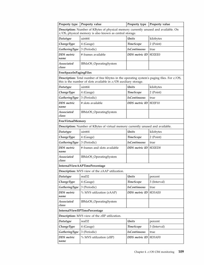
Property type Property value Property type Property value
Description: Number of KBytes of physical memory currently unused and available. Onz/OS, physical memory is also known as central storage.
Datatype uint64 Units kilobytes
ChangeType 4 (Gauge) TimeScope 2 (Point)
GatheringType 3 (Periodic) IsContinuous true
DDS metricname
# frames available DDS metric ID 8D2EE0
Associatedclass
IBMzOS_OperatingSystem
FreeSpaceInPagingFiles
Description: Total number of free Kbytes in the operating system's paging files. For z/OS,this is the number of slots available in z/OS auxiliary storage.
Datatype uint64 Units kilobytes
ChangeType 4 (Gauge) TimeScope 2 (Point)
GatheringType 3 (Periodic) IsContinuous true
DDS metricname
# slots available DDS metric ID 8D2F10
Associatedclass
IBMzOS_OperatingSystem
FreeVirtualMemory
Description: Number of KBytes of virtual memory currently unused and available.
Datatype uint64 Units kilobytes
ChangeType 4 (Gauge) TimeScope 2 (Point)
GatheringType 3 (Periodic) IsContinuous true
DDS metricname
# frames and slots available DDS metric ID 8D2ED0
Associatedclass
IBMzOS_OperatingSystem
InternalViewAAPTimePercentage
Description: MVS view of the zAAP utilization.
Datatype real32 Units percent
ChangeType 4 (Gauge) TimeScope 3 (Interval)
GatheringType 3 (Periodic) IsContinuous true
DDS metricname
% MVS utilization (zAAP) DDS metric ID 8D3AE0
Associatedclass
IBMzOS_OperatingSystem
InternalViewIIPTimePercentage
Description: MVS view of the zIIP utilization.
Datatype real32 Units percent
ChangeType 4 (Gauge) TimeScope 3 (Interval)
GatheringType 3 (Periodic) IsContinuous true
DDS metricname
% MVS utilization (zIIP) DDS metric ID 8D3AF0
Chapter 4. z/OS CIM monitoring 109

Property type Property value Property type Property value
Associatedclass
IBMzOS_OperatingSystem
InternalViewTotalCPUTimePercentage
Description: MVS view of the CP utilization, only available for LPARs in which z/OS RMFis active.
Datatype real32 Units percent
ChangeType 4 (Gauge) TimeScope 3 (Interval)
GatheringType 3 (Periodic) IsContinuous true
DDS metricname
% MVS utilization (CP) DDS metric ID 8D0420
Associatedclass
IBMzOS_OperatingSystem
KernelModeTime
Description: Time in kernel mode on the operating system level. On z/OS, this is mappedto uncaptured time.
Datatype uint64 Units milliseconds
ChangeType 4 (Gauge) TimeScope 3 (Interval)
GatheringType 3 (Periodic) IsContinuous true
DDS metricname
uncaptured time DDS metric ID 8D3240
Associatedclass
IBMzOS_OperatingSystem
LoadAverage
Description: Average in-ready queue length, that is, the number of workloads queued tobe executed on a CP processor. In relation to the number of available CPs, this metric canbe used as a CPU contention indicator, because workloads waiting in the in-ready queueare delayed for CPU resources.
Datatype real32 Units queue length
ChangeType 4 (Gauge) TimeScope 2 (Point)
GatheringType 3 (Periodic) IsContinuous true
DDS metricname
load average DDS metric ID 8D30E0
Associatedclass
IBMzOS_OperatingSystem
LocalPI (breakdown dimension: WLM service class period)
Description: Local performance index; the performance index of the MVS image on whichthe contacted CIM provider is running.
Datatype real32 Units n/a
ChangeType 4 (Gauge) TimeScope 3 (Interval)
GatheringType 3 (Periodic) IsContinuous true
DDS metricname
performance index by WLMservice class period
DDS metric ID 8D1020
Associatedclass
IBMzOS_OperatingSystem
NumberOfProcesses
110 z/OS RMF Programmer's Guide

Property type Property value Property type Property value
Description: Number of z/OS address spaces active during the sample interval.
Datatype uint32 Units processes
ChangeType 4 (Gauge) TimeScope 2 (Point)
GatheringType 3 (Periodic) IsContinuous true
DDS metricname
# users DDS metric ID 8D0D50
Associatedclass
IBMzOS_OperatingSystem
NumberOfUsers
Description: Number of user sessions for which the operating system is currently storingstate information. On z/OS, this is mapped to the number of TSO users currently active onthe z/OS image.
Datatype uint32 Units users
ChangeType 4 (Gauge) TimeScope 2 (Point)
GatheringType 3 (Periodic) IsContinuous true
DDS metricname
# users (Work scope: WLMWorkload: TSO)
DDS metric ID 8D0D50
Associatedclass
IBMzOS_OperatingSystem
OperationalStatus
Description: Overall status of the associated CIM_OperatingSystem resource (= z/OSimage). Currently, two states can be shown by the z/OS implementation:
v 'Stressed' (= 0x10 as metric value), indicating that the system is severely overloaded
v 'Ok' (= 0x04 as metric value).
If the workflow with workscope SYSTEM is less than 60%, the system is reported to be'Stressed', because in this case, even the workloads with highest priority are significantlydelayed.
Datatype uint32 Units n/a
ChangeType n/a TimeScope 2 (Point)
GatheringType 3 (Periodic) IsContinuous false
DDS metricname
% workflow (based on DDSmetric 0x8D0550 with workscope: WLM Workload:SYSTEM)
DDS metric ID 8D0550
Associatedclass
IBMzOS_OperatingSystem
PageInRate
Description: Number of pages paged in per second.
Datatype uint64 Units events per second
ChangeType 4 (Gauge) TimeScope 3 (Interval)
GatheringType 3 (Periodic) IsContinuous true
DDS metricname
pagein rate DDS metric ID 8D30F0
Associatedclass
IBMzOS_OperatingSystem
Chapter 4. z/OS CIM monitoring 111

Property type Property value Property type Property value
PercentDelay (z/OS only)
Description: Percentage of samples during which the z/OS operating system was delayedfor some resources.
Datatype real32 Units percent
ChangeType 4 (Gauge) TimeScope 3 (Interval)
GatheringType 3 (Periodic) IsContinuous true
DDS metricname
% delay DDS metric ID 8D0160
Associatedclass
IBMzOS_OperatingSystem
RGCappingDelaySamples (breakdown dimension: WLM service class period)
Description: Resource group capping delay samples percentage.
Datatype real32 Units percent
ChangeType 4 (Gauge) TimeScope 3 (Interval)
GatheringType 3 (Periodic) IsContinuous true
DDS metricname
% of RG capping delay samplesby WLM service class period
DDS metric ID 8D3880
Associatedclass
IBMzOS_OperatingSystem
SRBTimePercentage (breakdown dimension: WLM service class period)
Description: Percentage of SRB time used by all work in the system, or by WLM classes.This metric is divided by the number of processors. It does not include zAAP and zIIPtimes.
Datatype real32 Units percent
ChangeType 4 (Gauge) TimeScope 3 (Interval)
GatheringType 3 (Periodic) IsContinuous true
DDS metricname
% SRB by WLM service classperiod
DDS metric ID 8D2D40
Associatedclass
IBMzOS_OperatingSystem
SysplexPI (breakdown dimension: WLM service class period)
Description: Sysplex performance index.
Datatype real32 Units n/a
ChangeType 4 (Gauge) TimeScope 3 (Interval)
GatheringType 3 (Periodic) IsContinuous true
DDS metricname
performance index by WLMservice class period
DDS metric ID 8D1020
Associatedclass
IBMzOS_OperatingSystem
TCBTimePercentage (breakdown dimension: WLM service class period)
Description: Percentage of TCB time used by all work in the system, or by WLM classes.This metric is divided by the number of processors. It does not include zAAP and zIIPtimes.
Datatype real32 Units percent
ChangeType 4 (Gauge) TimeScope 3 (Interval)
112 z/OS RMF Programmer's Guide

Property type Property value Property type Property value
GatheringType 3 (Periodic) IsContinuous true
DDS metricname
% TCB by WLM service classperiod
DDS metric ID 8D2D50
Associatedclass
IBMzOS_OperatingSystem
TotalAAPTimePercentage
Description: zAAP utilization percentage
Datatype real32 Units percent
ChangeType 4 (Gauge) TimeScope 3 (Interval)
GatheringType 3 (Periodic) IsContinuous true
DDS metricname
% CPU utilization (zAAP) DDS metric ID 8D39B0
Associatedclass
IBMzOS_OperatingSystem
TotalAAPTimePercentage (breakdown dimension: WLM service class period)
Description: zAAP utilization percentage for a given WLM service class period)
Datatype real32 Units percent
ChangeType 4 (Gauge) TimeScope 3 (Interval)
GatheringType 3 (Periodic) IsContinuous true
DDS metricname
% zAAP DDS metric ID 8D2C60
Associatedclass
IBMzOS_OperatingSystem
TotalAAPonCPTimePercentage (breakdown dimension: WLM service class period)
Description: Total zAAP on CP time percentage.
Datatype real32 Units percent
ChangeType 4 (Gauge) TimeScope 3 (Interval)
GatheringType 3 (Periodic) IsContinuous true
DDS metricname
% zAAP on CP by WLM serviceclass period
DDS metric ID 8D2D00
Associatedclass
IBMzOS_OperatingSystem
TotalCPUTime
Description: Total system CPU time used.
Datatype uint64 Units milliseconds
ChangeType 4 (Gauge) TimeScope 3 (Interval)
GatheringType 3 (Periodic) IsContinuous true
DDS metricname
total time DDS metric ID 8D31F0
Associatedclass
IBMzOS_OperatingSystem
TotalIIPonCPTimePercentage (breakdown dimension: WLM service class period)
Description: zIIP on CP time percentage.
Datatype real32 Units percent
Chapter 4. z/OS CIM monitoring 113

Property type Property value Property type Property value
ChangeType 4 (Gauge) TimeScope 3 (Interval)
GatheringType 3 (Periodic) IsContinuous true
DDS metricname
% zIIP on CP by WLM serviceclass period
DDS metric ID 8D35D0
Associatedclass
IBMz_OperatingSystem
TotalIIPTimePercentage
Description: zIIP utilization percentage.
Datatype real32 Units percent
ChangeType 4 (Gauge) TimeScope 3 (Interval)
GatheringType 3 (Periodic) IsContinuous true
DDS metricname
% CPU utilization (zIIP) DDS metric ID 8D39C0
Associatedclass
IBMzOS_OperatingSystem
TotalIIPTimePercentage (breakdown dimension: WLM service class period)
Description: zIIP utilization percentage for a given WLM service class period)
Datatype real32 Units percent
ChangeType 4 (Gauge) TimeScope 3 (Interval)
GatheringType 3 (Periodic) IsContinuous true
DDS metricname
% CP utilization (zIIP) DDS metric ID 8D3520
Associatedclass
IBMzOS_OperatingSystem
UserModeTime
Description: Time in user mode on operating system level.
On z/OS, this is mapped to captured time.
Datatype uint64 Units milliseconds
ChangeType 4 (Gauge) TimeScope 3 (Interval)
GatheringType 3 (Periodic) IsContinuous true
DDS metricname
captured time DDS metric ID 8D3030
Associatedclass
IBMzOS_OperatingSystem
IBMzOS_ComputerSystemThis class provides basic computer system information such as computer name,and status information. It represents either virtual or physical computer systems inthe sense of a container inside which an operating system runs. On zSeries, thisclass represents either an LPAR or a z/VM® guest.
Property type Property value Property type Property value
ActiveVirtualProcessors
114 z/OS RMF Programmer's Guide
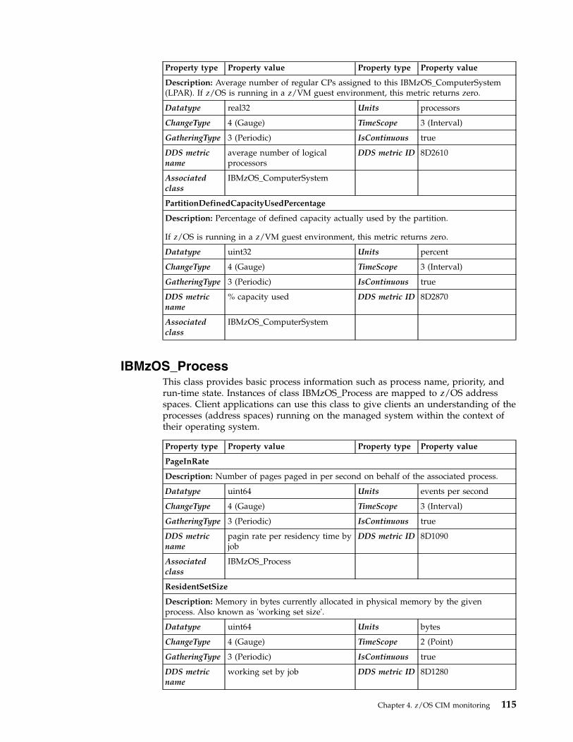
Property type Property value Property type Property value
Description: Average number of regular CPs assigned to this IBMzOS_ComputerSystem(LPAR). If z/OS is running in a z/VM guest environment, this metric returns zero.
Datatype real32 Units processors
ChangeType 4 (Gauge) TimeScope 3 (Interval)
GatheringType 3 (Periodic) IsContinuous true
DDS metricname
average number of logicalprocessors
DDS metric ID 8D2610
Associatedclass
IBMzOS_ComputerSystem
PartitionDefinedCapacityUsedPercentage
Description: Percentage of defined capacity actually used by the partition.
If z/OS is running in a z/VM guest environment, this metric returns zero.
Datatype uint32 Units percent
ChangeType 4 (Gauge) TimeScope 3 (Interval)
GatheringType 3 (Periodic) IsContinuous true
DDS metricname
% capacity used DDS metric ID 8D2870
Associatedclass
IBMzOS_ComputerSystem
IBMzOS_ProcessThis class provides basic process information such as process name, priority, andrun-time state. Instances of class IBMzOS_Process are mapped to z/OS addressspaces. Client applications can use this class to give clients an understanding of theprocesses (address spaces) running on the managed system within the context oftheir operating system.
Property type Property value Property type Property value
PageInRate
Description: Number of pages paged in per second on behalf of the associated process.
Datatype uint64 Units events per second
ChangeType 4 (Gauge) TimeScope 3 (Interval)
GatheringType 3 (Periodic) IsContinuous true
DDS metricname
pagin rate per residency time byjob
DDS metric ID 8D1090
Associatedclass
IBMzOS_Process
ResidentSetSize
Description: Memory in bytes currently allocated in physical memory by the givenprocess. Also known as 'working set size'.
Datatype uint64 Units bytes
ChangeType 4 (Gauge) TimeScope 2 (Point)
GatheringType 3 (Periodic) IsContinuous true
DDS metricname
working set by job DDS metric ID 8D1280
Chapter 4. z/OS CIM monitoring 115

Property type Property value Property type Property value
Associatedclass
IBMzOS_Process
TotalCPUTime
Description: Amount of CPU time used by the given process.
Datatype uint64 Units milliseconds
ChangeType 4 (Gauge) TimeScope 3 (Interval)
GatheringType 3 (Periodic) IsContinuous true
DDS metricname
eappl time by job DDS metric ID 8D3070
Associatedclass
IBMzOS_Process
UserModeTime
Description: CPU time used in user mode specifically for the given process. On z/OS thisis currently the same as TotalCPUTime.
Datatype uint64 Units milliseconds
ChangeType 4 (Gauge) TimeScope 3 (Interval)
GatheringType 3 (Periodic) IsContinuous true
DDS metricname
eappl time by job DDS metric ID 8D3070
Associatedclass
IBMzOS_Process
IBMzOS_UnixProcessThis class provides basic information about z/OS processes running in the z/OSUNIX System Services. It implements all properties from CIM_Process plus a set ofproperties typical for UNIX processes.
Property type Property value Property type Property value
AccumulatedTotalCPUTime
Description: CPU time in seconds spent for this process since USS process creation.
Datatype real32 Units seconds
ChangeType 3 (Counter) TimeScope 4 (Startup Interval)
GatheringType 3 (Periodic) IsContinuous true
DDS metricname
total cpu seconds by uss pidand jobname
DDS metric ID 8D31E0
Associatedclass
IBMzOS_UnixProcess
ExternalViewUserModePercentage
Description: Usage percentage of the system CPUs for this process in user mode duringthe measurement interval.
Datatype real32 Units percent
ChangeType 4 (Gauge) TimeScope 3 (Interval)
GatheringType 3 (Periodic) IsContinuous true
DDS metricname
% appl by uss pid and jobname DDS metric ID 8D2830
116 z/OS RMF Programmer's Guide

Property type Property value Property type Property value
Associatedclass
IBMzOS_UnixProcess
IBMzOS_ChannelInstances of this class represent z/OS channels, with property DeviceID containingthe Channel Path ID (CHPID). The purpose of this resource class is to enable theassociation of related metrics.
Property type Property value Property type Property value
BusUtilization
Description: Percentage of bus cycles, the bus has been found busy for this channel inrelation to the theoretical limit.
Datatype real32 Units percent
ChangeType 4 (Gauge) TimeScope 3 (Interval)
GatheringType 3 (Periodic) IsContinuous true
DDS metricname
% bus utilization DDS metric ID 8D2360
Associatedclass
IBMzOS_Channel
BytesReceived
Description: Total number of bytes received per second, including framing characters
Datatype uint64 Units bytes
ChangeType 4 (Gauge) TimeScope 3 (Interval)
GatheringType 3 (Periodic) IsContinuous true
DDS metricname
total bytes read/sec DDS metric ID 8D23D0
Associatedclass
IBMzOS_Channel
BytesTransmitted
Description: Total number of bytes transmitted per second, including framing characters.
Datatype uint64 Units bytes
ChangeType 4 (Gauge) TimeScope 3 (Interval)
GatheringType 3 (Periodic) IsContinuous true
DDS metricname
total bytes written/sec DDS metric ID 8D23F0
Associatedclass
IBMzOS_Channel
ErrorRate
Description: Number of network errors per second.
Datatype real32 Units errors per second
ChangeType 4 (Gauge) TimeScope 3 (Interval)
GatheringType 3 (Periodic) IsContinuous true
DDS metricname
send fail/sec DDS metric ID 8D31C0
Chapter 4. z/OS CIM monitoring 117

Property type Property value Property type Property value
Associatedclass
IBMzOS_Channel
NetworkPortUtilizationPercentage
Description: Percentage of z/OS channel capacity actually used. This number may not beprecise, meaning that for some non-ideal work loads (like transferring lots of very shortmessages), it may not be possible to reach 100% utilization.
Datatype real32 Units percent
ChangeType 4 (Gauge) TimeScope 3 (Interval)
GatheringType 3 (Periodic) IsContinuous true
DDS metricname
% total utilization DDS metric ID 8D0080
Associatedclass
IBMzOS_Channel
PartitionBytesReceived (z/OS only)
Description: Total number of bytes received.
Datatype uint64 Units bytes
ChangeType 4 (Gauge) TimeScope 3 (Interval)
GatheringType 3 (Periodic) IsContinuous true
DDS metricname
partition bytes read/sec DDS metric ID 8D2390
Associatedclass
IBMzOS_Channel
PartitionBytesTransmitted (z/OS only)
Description: Total number of bytes transmitted.
Datatype uint64 Units bytes
ChangeType 4 (Gauge) TimeScope 3 (Interval)
GatheringType 3 (Periodic) IsContinuous true
DDS metricname
partition bytes written/sec DDS metric ID 8D23B0
Associatedclass
IBMzOS_Channel
PartitionUtilization
Description: Channel path utilization percentage for an individual logical partition.
Datatype real32 Units percent
ChangeType 4 (Gauge) TimeScope 3 (Interval)
GatheringType 3 (Periodic) IsContinuous true
DDS metricname
% partition utilization DDS metric ID 8D0060
Associatedclass
IBMzOS_Channel
ReceiveErrorRate (z/OS only)
Description: Number of network errors per second related to receiving activities of thechannel.
Datatype real32 Units errors per second
118 z/OS RMF Programmer's Guide

Property type Property value Property type Property value
ChangeType 4 (Gauge) TimeScope 3 (Interval)
GatheringType 3 (Periodic) IsContinuous true
DDS metricname
receive fail/sec DDS metric ID 8D3160
Associatedclass
IBMzOS_Channel
TotalUtilization
Description: Channel path utilization percentage for the entire system during the interval.
Datatype real32 Units percent
ChangeType 4 (Gauge) TimeScope 3 (Interval)
GatheringType 3 (Periodic) IsContinuous true
DDS metricname
% total utilization DDS metric ID 8D0080
Associatedclass
IBMzOS_Channel
IBMzOS_UnixLocalFileSystemThis class represents UNIX file systems that are locally attached to a computersystem. On z/OS, the hierarchical file system zFS is supported.
Note: The class IBMzOS_UnixLocalFileSystem is inherited from CIM_FileSystem.
Property type Property value Property type Property value
AvailableSpace
Description: Total amount of free space for the associated file system in bytes. This metricis not implemented based on RMF data.
Datatype uint64 Units bytes
ChangeType 4 (Gauge) TimeScope 2 (Point)
GatheringType 4 (OnRequest) IsContinuous true
DDS metricname
none DDS metric ID none
Associatedclass
IBMzOS_UnixLocalFileSystem
Chapter 4. z/OS CIM monitoring 119

120 z/OS RMF Programmer's Guide

Chapter 5. Adding Monitor I and Monitor II installation exits
This chapter describes:v How to create Monitor I user exit routinesv How to create Monitor II user reports
OverviewFacilities in RMF allow you to gather and report data relevant to your installation.
During a Monitor I session, installation exits let you sample data at each RMFcycle, collect this data and examine system indicators at each RMF interval, formatand write your own SMF records, and format and write your own reports. You canalso use the RMF trace facilities to trace the contents of any SQA, fixed CSA, ornucleus field that you require. During a Monitor II session, the data interfaceservice allows you to directly access SMF record data from storage in real timerather than through SMF. The service provides easy access to this data by invokingthe module ERBSMFI.
During a Monitor II session, installation exits enable you to gather and report yourown data by coding your own data-gathering and data-reporting routines. RMFprovides the USER option for a background session and the USER menu item for adisplay session. To generate one additional report, you replace module ERBGUS99with your data gatherer and ERBRUS99 with your data reporter. Specifying USERthen causes your own report to be generated. Should you want to obtain morethan one user report, you must add an entry to the option list or menu list as wellas supply a data-gathering and a data-reporting routine. Data gathered for yourroutine can be reported either during the session or during execution of thePostprocessor.
During a Monitor II TSO/E display session, with TSO/E installed, a user exitenables your installation to verify that a terminal user is authorized to use RMF.See “TSO terminal user authorization” on page 145 for an explanation of this userexit.
Monitor I session user reportsTo gather and report data relevant to your installation during a Monitor I session,RMF provides both the EXITS option and installation exits at various points duringMonitor I session processing. When EXITS is specified, you can:v Initialize for the other user exit routinesv Sample fixed CSA, SQA, or nucleus data at each RMF cyclev Perform interval processing, for example, reduce sampled data, examine system
state indicators, format SMF records to be written to the SMF data set or passedto your report writer
v Write reports during a sessionv Handle termination processing for the other installation exitsv Write reports during execution of the Postprocessor.
© Copyright IBM Corp. 1990, 2017 121

In addition, you can use the Monitor I session tracing routines to trace the contentsof a fixed SQA, CSA, or nucleus field regardless of whether or not EXITS isspecified.
GuidelinesEach of the user functions is described in detail in the following sections. Thefollowing guidelines apply to Monitor I user exit routines:v All of the user exit routines must be reenterable.v All user-written exit routines receive control in 31-bit addressing mode.v The routines must save registers when they receive control and restore registers
when they return control. Register 13 contains the address of the register savearea; register 14 contains the return address; and register 15 contains the entryaddress.
v One input parameter that RMF passes to each user exit routine (except thetracing routine and the Postprocessor user exit) is the address of a two-wordarea reserved for the use of your routines. Because these words provide a meansof communication between your exit routines, their use should be controlled byconventions agreed upon by your installation.
v RMF passes a phase parameter to each user exit routine except the sampler, thetracing routine, and the Postprocessor user exit. This phase parameter indicateswhich RMF phase is invoking the user exit.
RMF provides dummy routines for all Monitor I session exits that are not used.
CautionBecause all of the user exit routines except ERBMFRUR (the report writer) run insupervisor state with a key of 0, your installation must carefully control their use.Program errors that cause an exit routine to overlay system areas could bringdown the system.
Initialization for Monitor I session user exit routinesThe initialization user exit is ERBMFIUC. It is called at the start of a Monitor Isession and whenever the Monitor I session options are modified. Use this exit toperform any initialization the other installation exits require, such as building acontrol block structure.
When the exit routine gets control, register 1 points to a three-word address list.The first address points to the two-word area reserved for use by your routines.This same two-word area is passed to all the user exit routines and can be used forcommunication between them. The second address points to the RMF phaseparameter, a full-word field that is always X‘4:’, indicating that the exit is calledduring Monitor I session initialization. The third address points to a word that isrelevant only when you are providing a routine to sample data at each cycle; oneof the functions your initialization routine will perform is to put the address of theuser sampler in this word. Figure 15 on page 123 illustrates the input parameterstructure.
When the initialization routine is entered, the system is in supervisor state, and allinterrupts are enabled. ERBMFIUC runs in key 0.
Special initialization procedures are required when your user routines include asampling routine to sample data at each cycle; see “Sampling Data at Each Cycle.”When you have a user sampler, your initialization routine must do the following:
Mon I overview
122 z/OS RMF Programmer's Guide

v The user sampling routine must be loaded and page fixed. You must use thePGSER macro to page fix the user sampler routine because the sampler coderuns disabled.
v The address of the user sampling routine must be placed in the third inputparameter.
v All storage the sampler routine will require must be obtained; this storage mustbe obtained from SQA (subpool 245).
v The address of the SQA storage obtained must be placed in one of the two userwords. The choice depends on the conventions established at your installation.
When you have completed the initialization required by all the installation exits,return control by branching on register 14.
Sampling data at each cycleTo sample data at each cycle, the steps described earlier for initialization must beperformed to load and page fix the user sampler routine. A user sampler routine isactivated at each cycle only when another measurement that includes a samplingroutine is activated. These measurements include paging activity, page/swap dataset activity, channel path activity, I/O queuing activity, device activity, and traceactivity. At least one of these measurements must be specified to enable RMF toinvoke your user sampler.
When the sampler gets control, register 1 points to a two-word area. One of thesewords, selected by your installation, contains the address of the storage areaobtained for the sampler by ERBMFIUC. Figure 16 on page 124 illustrates the inputparameter structure.
When the user sampler is entered, the system is in supervisor state, and allinterrupts are disabled. The routine runs in key 0. It can sample any fixed data inCSA, SQA, or the nucleus; no other data areas can be sampled. You place the datasampled in the storage area obtained by ERBMFIUC and passed to you when yourroutine is invoked. This storage area is always in SQA (subpool 245). At the end ofthe RMF interval, RMF passes the address of the storage area to the user intervalprocessing routine. Should your routine cause a page fault, the Monitor I sessionterminates abnormally with an abend code of 0FE.
When your sampling is completed, return control by branching on register 14.
Figure 15. ERBMFIUC Input Parameter Structure
Mon I initialization
Chapter 5. Adding Monitor I and Monitor II installation exits 123

Note: The user sampler must reside in SYS1.SERBLPA. See “Adding Your Routinesto RMF” later in this chapter.
Interval processingThe interval processing user exit is ERBMFDUC. It is invoked at the start of theMonitor I session and at the end of each RMF interval.
When the exit gets control, register 1 points to a two-word address list. The firstaddress points to the two-word area reserved for use by your routines. When theseroutines include a user sampler, one of these words, selected by your installation,will contain the address of the sampled data. The second address points to theRMF phase parameter. This parameter is a full word that contains X‘4’ when theexit is called during Monitor I session initialization, X‘8’ when the exit is called atthe end of an RMF interval, or X‘C’ when the exit is called at the end of an RMFinterval for which data collection was skipped. Figure 17 on page 125 illustrates theinput parameter structure.
When the interval processing exit routine is entered, the system is in supervisorstate, and all interrupts are enabled. The routine runs in key 0. The routine canprocess the data generated by the user sampler. It can also collect its own datafrom system control blocks or system state indicators and format an SMF record.The SMF record can be written to the SMF data set; see z/OS MVS SystemManagement Facilities (SMF) for details on using the SMFEWTM macro instructionto write a user SMF record.
The SMF record or a record your routine formats as agreed by convention betweenERBMFDUC and ERBMFRUR (the report writer exit routine) can be printed byyour report writer. Your routine can format SMF record output, report recordoutput, or both. When your routine formats any records to be printed by yourreport writer, the address of the formatted records must be placed in the user wordselected by your installation. Because the user words are passed to your reportwriter, the records can then be printed in a formatted report.
When the length of the RMF interval exceeds 99 minutes, which can occur whenRMF is not dispatched at the end of an interval, data collection for the interval isskipped. Because there is no data collected, RMF does not call the report writeruser exit (ERBMFRUR); instead, ERBMFDUC is called twice. The phase parameteris X‘8’ for the first invocation of the exit routine and X‘C’ for the second. When theexit routine is called with a phase parameter of X‘C’, your routine must free thestorage areas normally freed by ERBMFRUR. RMF issues a message to notify theoperator that data collection was skipped for the interval.
When your routine has completed processing, return control by branching onregister 14.
Figure 16. User Sampler Input Parameter Structure
Mon I sampling
124 z/OS RMF Programmer's Guide
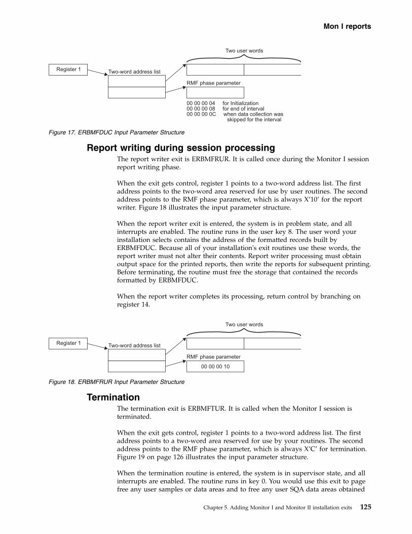
Report writing during session processingThe report writer exit is ERBMFRUR. It is called once during the Monitor I sessionreport writing phase.
When the exit gets control, register 1 points to a two-word address list. The firstaddress points to the two-word area reserved for use by user routines. The secondaddress points to the RMF phase parameter, which is always X‘10’ for the reportwriter. Figure 18 illustrates the input parameter structure.
When the report writer exit is entered, the system is in problem state, and allinterrupts are enabled. The routine runs in the user key 8. The user word yourinstallation selects contains the address of the formatted records built byERBMFDUC. Because all of your installation's exit routines use these words, thereport writer must not alter their contents. Report writer processing must obtainoutput space for the printed reports, then write the reports for subsequent printing.Before terminating, the routine must free the storage that contained the recordsformatted by ERBMFDUC.
When the report writer completes its processing, return control by branching onregister 14.
TerminationThe termination exit is ERBMFTUR. It is called when the Monitor I session isterminated.
When the exit gets control, register 1 points to a two-word address list. The firstaddress points to a two-word area reserved for use by your routines. The secondaddress points to the RMF phase parameter, which is always X‘C’ for termination.Figure 19 on page 126 illustrates the input parameter structure.
When the termination routine is entered, the system is in supervisor state, and allinterrupts are enabled. The routine runs in key 0. You would use this exit to pagefree any user samples or data areas and to free any user SQA data areas obtained
Figure 17. ERBMFDUC Input Parameter Structure
Figure 18. ERBMFRUR Input Parameter Structure
Mon I reports
Chapter 5. Adding Monitor I and Monitor II installation exits 125

by the other exits, with one exception: during termination processing, ERBMFTURgets control before the report writer exit (ERBMFRUR). Therefore, it must free onlythe SQA and global storage the other user routines obtained, but it must not freethe storage the interval processing routine (ERBMFDUC) used to build records tobe passed to the report writer. The address of this storage will be in the user wordselected by your installation.
When the termination routine has completed processing, return control bybranching on register 14.
Tracing your own fieldWhenever the TRACE option is in effect during a Monitor I session, you can usethe tracing routines to trace the contents of any SQA, CSA, or nucleus field thatyou require. The EXITS option, required to generate your own reports, is notrequired to use the trace facilities because the trace exit, ERBTRACE, is calledwhenever the TRACE option is in effect.
The field that you want to trace must be fixed in CSA, SQA, or the nucleus; itcannot contain negative values; and it must be from one to four bytes in length.Once you have selected your field, there are two steps required to enable RMF totrace the contents of the field. After you have performed these steps, you can thenspecify the name in the field name portion of the TRACE option. The steps can beperformed in any order, but both must be done before you can use RMF to tracethe field.
Step 1 -- Defining the name to RMFTo define the name, you must add four fields to the RMF CSECT ERBMFTTB,which contains the names RMF recognizes as valid for tracing. The fields you mustadd are:1. The name of the field to be traced. The name can be from one to eight bytes
long. It must not be the same as any name already recognized by RMF. Whenthe name of the field is less than eight bytes long, it must be padded on theright with blanks to a length of eight bytes.
2. The length of the name. This field is one byte long; the value must be from 01to 08.
3. A one-byte constant that always contains the value X‘DC’.4. The length of the field to be traced. This field is one byte long; the value must
be from 01 to 04.
One byte of binary zeroes must follow the last entry to be added; the byte ofbinary zeroes indicates the end of the variable-length trace table. Figure 20 on page127 shows an example of how to superzap ERBMFTTB to add a new name fortracing. The parenthesized numbers in the text refer to the parenthesized numbersin the figure. The example adds a nucleus field named MYDATA (1) that is twobytes in length (4) to the list of names valid for RMF tracing. The name is six bytes
Figure 19. ERBMFTUR Input Parameter Structure
Mon I stopping
126 z/OS RMF Programmer's Guide

long (2), and the required constant is also supplied (3). A byte of binary zeroes (5)indicates the end of the trace table. Adding the name definition to ERBMFTTBcauses RMF to pass the name to ERBTRACE during each tracing cycle. The fourfields must be added for each name you want RMF to trace; only the last entrymust be followed by the byte of binary zeroes.
Step 2 -- Replacing ERBTRACEThe tracing user exit is ERBTRACE. The function of ERBTRACE is to return toRMF the address of a valid user field. It is called by the RMF tracing routinewhenever it encounters a trace name that is not the name of a field in the SRMdomain table. To trace your own field, you must replace ERBTRACE with yourown routine and link edit your ERBTRACE with the RMF CSECT ERBMFITR.
When ERBTRACE gets control, register 1 points to a two-word address list. Thefirst address points to an eight-byte field that holds the name to be validated. Thesecond address points to a full word to be used by ERBTRACE to return theaddress of the user field to RMF. Figure 21 illustrates the input parameterstructure.
When ERBTRACE is entered, the system is in supervisor state, and all interruptsare enabled. The routine runs in key 0. It must examine the field name passed to itby RMF to determine if the name is a user field name. When the name is a validuser name, place the address of the field to be traced in the first parameter, set areturn code of zero in register 15, and return control. If the name is not onerecognized as a valid user name, always set a non-zero return code in register 15before returning control. The non-zero return code tells RMF to process the name.
When your processing is completed, return control by branching on register 14.
//ZAP JOB MSGLEVEL=1//SS EXEC PGM=AMASPZAP//SYSPRINT DD SYSOUT=A//SYSLIB DD DSN=SYS1.SERBLINK,DISP=SHR//SYSIN DD *
NAME ERBMFMFC ERBMFTTBVER 040C 0040D7C1REP 040C D4E8C4C1E3C14040 (1)REP 0414 06 (2)REP 0415 DC (3)REP 0416 02 (4)REP 0417 00 (5)
/*
Figure 20. Example of Adding a Name to ERBMFTTB
Figure 21. ERBTRACE Input Parameter Structure
Mon I trace
Chapter 5. Adding Monitor I and Monitor II installation exits 127

Report writing by the PostprocessorThe Postprocessor user exit is ERBMFPUS. It is called during post-processing at thepoint when the Postprocessor first encounters each SMF record. When the exit getscontrol, register 1 points to a three-word address list:v The first address points to a full word that contains the address of the SMF
record to be processed.v The second address points to a full word reserved for the use of your routine.
The user word contains zeros the first time the exit is called, and thePostprocessor does not modify its contents between invocations of the user exitroutine. Thus, the word can be used to save information, such as the address ofa DCB, that is needed by a subsequent invocation of the user exit routine.
v The third address points to a FIXED(8) field, which contains X'01' for EOF.
Figure 22 illustrates the input parameter structure.
When the Postprocessor user exit is entered, the system is in problem state and allinterrupts are enabled. The routine runs in the user key 8.
Your routine examines the SMF record passed to you, performs any requiredprocessing, and set a return code in register 15. The return code depends on theaction you want the Postprocessor to take. A return code of 0 tells thePostprocessor to continue processing the SMF record. A return code of 4 tells thePostprocessor to ignore the SMF record; set a return code of 4 when the exitroutine has, for example, processed the record or determined that it should not beprocessed. A return code of 8 indicates that the Postprocessor should terminate.
The processing your exit performs can consist of formatting the data in the recordsthat the interval processing user exit routine (ERBMFDUC) generates into a printedreport. Your exit could also screen the SMF records that the Postprocessorencounters to determine which records are to be included in any reports generatedby the Postprocessor, or it could use the SMF records RMF generates as input toyour own report. Because all SMF records are passed to the user exit, ERBMFPUScould also be used to incorporate any SMF data reduction routines used at yourinstallation into the RMF Postprocessor function.
When your routine has finished processing, set the appropriate return code inregister 15 and return control to the RMF Postprocessor by branching on register14.
Adding your routines to RMFBefore your Monitor I session user exit routines can be tested and used, they mustbe assembled and link edited with the appropriate RMF modules. If you are using
Figure 22. ERBMFPUS Input Parameter Structure
Postprocessor
128 z/OS RMF Programmer's Guide

your private libraries, you have to ensure that they are concatenated in front of thedistributed RMF libraries. Figure 23 shows sample JCL for performing the requiredlink edit for all user routines except the sampler routine. If you have a usersampler, a separate link edit is required; a sample is shown in Figure 24.
Monitor II session user reportsRMF generates a Monitor II session report by invoking a data-gathering moduleand a data-reporting module in response to either:v a menu item identifying a display session reportv an option identifying a background session report
From an external viewpoint, the menu item and the option are different becausethey are used during different types of sessions, have slightly different syntax, andproduce either display output or printed output. However, from an internal pointof view, the menu item and the option are very similar. The valid menu items for adisplay session are listed in the RMF CSECT ERBFMENU.
Note: If you are running the Kanji version of RMF, the corresponding CSECT isERBJMENU, and you should ensure that both CSECTs stay synchronized.
//LINKEXIT JOB MSGLEVEL=1//LINK0001 EXEC PGM=IEWL,PARM=’MAP,XREF,REUS,RENT,REFR,NCAL’//SYSPRINT DD SYSOUT=A//SYSLMOD DD DSN=SYS1.SERBLINK,DISP=(OLD,KEEP)//SYSUT1 DD UNIT=SYSDA,DISP=(,DELETE),SPACE=(TRK,(20,5))//SYSLIN DD *
(ERBMFIUC object deck)ENTRY ERBMFIUCNAME ERBMFIUC(R)(ERBMFDUC object deck)ENTRY ERBMFDUCNAME ERBMFDUC(R)(ERBMFRUR object deck)ENTRY ERBMFRURNAME ERBMFRUR(R)(ERBMFTUR object deck)ENTRY ERBMFTURNAME ERBMFTUR(R)(ERBTRACE object deck)INCLUDE SYSLMOD(ERBMFITR)ENTRY ERBMFITRNAME ERBMFITR(R)(ERBMFPUS object deck)ENTRY ERBMFPUSNAME ERBMFPUS(R)
/*
Figure 23. Replacing Installation Exits
//LINKEXIT JOB MSGLEVEL=1//LINK0001 EXEC PGM=IEWL,PARM=’MAP,XREF,REUS,RENT,REFR,NCAL’//SYSPRINT DD SYSOUT=A//SYSLMOD DD DSN=SYS1.SERBLPA,DISP=(OLD,KEEP)//SYSUT1 DD UNIT=SYSDA,DISP=(,DELETE),SPACE=(TRK,(20,5))//SYSLIN DD *
(user sampler object deck)ENTRY entry nameNAME sampler name
/*
Figure 24. Adding a User Sampler
Mon I linking
Chapter 5. Adding Monitor I and Monitor II installation exits 129

The options for a background session are listed in the RMF CSECT ERBBMENU.The formats of the entries in each list are identical. When an option or menu itemis specified during a session, RMF uses the data entry for the report in the listappropriate for the session type to verify that the option or menu item is valid andto load the required data gatherer and data reporter modules.
Each list contains an entry called USER that enables you to add a single userreport. When USER is specified, RMF loads modules ERBGUS99, the data gathererfor USER, and ERBRUS99, the data reporter for USER. By replacing these twomodules with your own routines, you can add a single report to the Monitor IIreports provided by RMF. This process is described later in this chapter under“Coding a User Report.”
The data gathering module and the data reporting module communicate through atype 79 SMF record. The data gatherer formats the record and completes therequired data fields. The data reporter uses the data in the record to generate aformatted report for printing or display. See “SMF Record Type 79.”
To add more than one Monitor II session report, you must, in addition toproviding a data gatherer and a data reporter, add an entry to ERBFMENU for adisplay session report and to ERBBMENU for a background session report. Then,when your option or menu item is specified during a session, RMF will load yourdata gatherer and data reporter to generate the report. The process to follow toadd an entry to the option list and menu list is described later in this chapterunder “Installing a User Report.”
GuidelinesEach of the user functions is described in detail in the following sections. Thefollowing guidelines apply to all Monitor II user exit routines.v All of the user exit routines must be reenterable.v All user-written exit routines receive control in 31-bit addressing mode.v The routines must save registers when they receive control and restore registers
when they return control. Register 13 contains the address of the register savearea; register 14 contains the return address; and register 15 contains the entryaddress.
v All of the user exit routines receive control in problem state, key 8.
SMF record type 79SMF record type 79 must be used to record data gathered by a user data gatheringroutine. Figure 25 on page 131 shows the layout of the record sections that arecommon to all Monitor II data gatherers, whether coded by a user or provided byRMF. The figure illustrates the layout of these common sections by showing theexpansion of the RMF mapping macro ERBSMF79.
The fields in the common sections fall into three categories. Each category isindicated by a letter in the figure that corresponds to the letters in the followingtext:
▌A▐ The fields that the RMF routines fill in before the data gathering routine isinvoked.
▌B▐ The fields that the data gathering routine must fill in during its processing.(See “Relocate Blocks” later in this section.)
▌C▐ The fields that the RMF routines will fill in when the RECORD option is in
Mon II overview
130 z/OS RMF Programmer's Guide

effect. RMF completes these fields after the data gatherer returns controlbut before the record is written to the SMF data set. During a displaysession or a background session when NORECORD is in effect, these fieldsare not completed because the record is not actually written to the SMFdata set.
Before invoking the data gatherer, RMF calculates the length of the storage bufferrequired for the record, as described later under “Relocate Blocks,” obtains a bufferfor the record, and fills in some of the common section fields. The address of theSMF record buffer is passed to the data gatherer. The data gatherer fills in somefields in the common section and all of the data section of the record.
******************** COMMON SMF HEADER *****************************SMF79HDR DSECT
▌C▐ SMF79LEN DS BL2 RECORD LENGTHSMF79SEG DS BL2 SEGMENT DESCRIPTOR
▌C▐ SMF79FLG DS BL1 HEADER FLAG BYTESMF79RRF EQU X’80’ NEW SMF RECORD FORMAT IF=1SMF79SUT EQU X’40’ SUBTYPE UTILIZED IF=1SMF79ESA EQU X’08’ MVS/ESA IF=1SMF79VXA EQU X’04’ MVS/XA IF=1SMF79OS EQU X’02’ OPERATING SYSTEM IS OS/VS2SMF79BFY EQU X’01’ SYSTEM IS RUNNING IN PR/SM MODESMF79PTN DS BL1 PR/SM PARTITION NUMBER
▌C▐ SMF79RTY DS BL1 RECORD TYPESMF79TME DS BL4 TOD RECORD WRITTENSMF79DTE DS PL4 DATE RECORD WRITTEN
▌C▐ SMF79SID DS CL4 SYSTEM ID FROM INSTALLATION▌C▐ SMF79SSI DS CL4 SUBSYSTEM ID (RMF)▌B▐ SMF79STY DS BL2 SUBTYPE▌A▐ SMF79TRN DS BL2 NUMBER OF TRIPLETS IN THIS RECORD
DS BL2 RESERVED▌A▐ SMF79PRS DS BL4 OFFSET TO RMF PRODUCT SECTION▌A▐ SMF79PRL DS BL2 LENGTH OF RMF PRODUCT SECTION▌A▐ SMF79PRN DS BL2 NUMBER OF RMF PRODUCT SECTIONS********************** INDIVIDUAL HEADER EXTENSION *******************
▌A▐ SMF79MCS DS F - OFFSET TO MONITOR II CONTROL SECTION▌A▐ SMF79MCL DS H - LENGTH OF MONITOR II CONTROL SECTION▌A▐ SMF79MCN DS H - NUMBER OF MONITOR II CONTROL SECTION▌B▐ SMF79ASS DS F - OFFSET TO DATA SECTION▌B▐ SMF79ASL DS H - LENGTH OF DATA SECTION
▌B▐▌A▐ SMF79ASN DS H - NUMBER OF DATA SECTION▌A▐ SMF79DCS DS F - OFFSET TO DATA CONTROL SECTION▌B▐ SMF79DCL DS H - LENGTH OF DATA CONTROL SECTION▌B▐ SMF79DCN DS H - NUMBER OF DATA CONTROL SECTION
SMF79QSS DS F - OFFSET IOQ GLOBAL SECTIONSMF79QSL DS H - LENGTH IOQ GLOBAL SECTIONSMF79QSN DS H - NUMBER IOQ GLOBAL SECTION
Figure 25. ERBSMF79 Mapping Macro Expansion
SMF record
Chapter 5. Adding Monitor I and Monitor II installation exits 131

Relocate blocksThe data section of SMF record type 79 is unique to each report. It is composed ofone or more data sections called relocate blocks and, possibly, one data controlsection. A relocate block is the portion of the SMF record that contains the data forone report data line. A record for a row report has one relocate block. A record fora table report has multiple relocate blocks; for example, the SMF record for theaddress space state data report includes one relocate block for each address spaceincluded in the report. When your SMF record has multiple relocate blocks andyou are gathering data that applies to all of them, you can, instead of reporting thedata in each relocate block, place this common data in a data control section, asdescribed later under “Data Control Section”.
The format of the data in the relocate block depends on the report you aregenerating. You set the format that best meets your needs. When you are
********************** COMMON SMF PRODUCT SECTION ********************SMF79PRO DSECT
▌C▐ SMF79MFV DS CL2 RMF VERSION NUMBER, WITH* INTRODUCTION OF THE MVS* SOFTWARE LEVEL, THE FORMAT* CHANGES TO PACKED (VRLF),
▌C▐ SMF79PRD DS CL8 PRODUCT NAMESMF79IST DS PL4 TOD MONITOR 1 INTERVAL START: OHHMMSSF
▌C▐ SMF79DAT DS PL4 DATE MONITOR 1 INTERVAL START: 00YYDDDFSMF79INT DS PL4 DURATION OF MONITOR 1 INTERVAL: MMSSTTTF* DS BL2 RESERVED
▌B▐ SMF79SAM DS BL4 NUMBER OF SAMPLES* DS BL2 RESERVEDSMF79FLA DS BL2 FLAGSSMF79ISS DS X’40’ INVALID SAMPLES TO BE SKIPPEDSMF79M3R DS X’20’ RECORD WAS WRITTEN BY RMF MONITOR IIISMF79ISM DS X’10’ INTERVAL WAS UNDER SMF CONTROL* DS BL4 RESERVED
▌B▐ SMF79CYC DS PL4 CYCLE IN PACKED DECIMAL 000TTTTF▌B▐ SMF79MVS DS CL8 MVS SOFTWARE LEVEL▌B▐ SMF79IML DS BL1 TYPE OF PROCESSOR COMPLEX ON WHICH DATA IS MEASURED▌B▐ SMF79PRF DS XL1 PROCESSOR FLAGS▌B▐ SMF79QES EQU X’80’ EQUIPPED WITH EXPANDED STORAGE▌B▐ SMF79CNE EQU X’40’ EQUIPPED WITH ESCON CHANNEL▌B▐ SMF79DRC EQU X’20’ ESCON DIRECTOR IN CONFIG.▌B▐ SMF79EME EQU X’10’ SYSTEM IS RUNNING IN Z/ARCHITECTURE▌B▐ SMF79PTN DS BLI PR/SM PARTITION NUMBER
SMF79SLR DS BL1 SMF RECORD LEVELSMF79IET DS CL8 INTERVAL EXPIRATION TIME TOKEN********************** MONITOR II CONTROL SECTION *******************R79CHL DSECT COMMON RECORD 79 HEADER
▌B▐ R79GTOD DS XL4 - DATA GATHERER CALL TOD▌B▐ R79LF2 DS XL1 - FLAG BYTE
R79PAR EQU X’80’ NOT ENOUGH RELOCATE SECTION TO* COMPLETE DATA GATHERINGR79SG EQU X’40’ REPORT TO BE SORTED BY SGR79RV1 DS XL1 - RESERVED
▌C▐ R79SES DS CL2 - SESSION NAMER79RSV DS XL2 - RESERVEDR79USER DS XL2 - USER FIELD
▌C▐ R79RID DS CL8 - MEASUREMENT NAME▌C▐ R79CTXTL DS XL2 - LEN OF COMMAND TEXT▌C▐ R79CTEXT DS CL32 - COMMAND TEXT▌C▐ R79DTXTL DS XL2 - LEN OF DEFAULT DR TEXT▌C▐ R79DTEXT DS CL32 - DEFAULT DR TEXT▌C▐ R79IST DS CL4 - MON III INTERVAL START TIME :0HH MMSSF
********************** DATA SECTION *********************************R799LCU DS BL2 LOGICAL CONTROL UNIT NUMBER 0 TO 255R799SGN DS CL8 STORAGE GROUP NAME
Figure 26. ERBSMF79 Mapping Macro Expansion (continued)
SMF record
132 z/OS RMF Programmer's Guide

generating a table report, the SMF record consists of multiple relocate blocks, andeach relocate block must have the same length.
When you add a menu item to ERBFMENU or an option to ERBBMENU, the entrythat describes the new report must include a field that specifies the length of therelocate block, the maximum number of possible relocate blocks, and the length ofthe data control section. For information on how to add an entry to ERBFMENU orERBBMENU, see “Using the PICTURE macro” on page 143. To determine thestorage to allocate, RMF multiplies the length of the relocate block by themaximum number of relocate blocks and adds this value to the length of the datacontrol section and the common section. The result of this computation is themaximum possible length of the SMF record, and RMF allocates a buffer for therecord that is equal in size to the maximum length.
To determine the actual length of the SMF record, the data gatherer must completethe fields in the individual header extension section that describe the offset, length,and number of data sections and the data control sections. After the data gathererhas completed its processing and returned control, RMF uses these values todetermine the length of the SMF record to be written to the SMF data set, acalculation that is performed only when the RECORD option is in effect for abackground session. Note that the value your routine sets in SMF79ASL and thevalue specified for RBLEN in the PICTURE macro for the report should beidentical.
Other fields in the common section that the data gather completes are R79GTODand SMF79STY. R79GTOD must contain a packed decimal value that indicates thetime when the data gatherer was invoked, in the form 0hhmmssF, where F is thesign. SMF79STY can contain the subtype number of the SMF record that you arecreating. You use this number as a unique identifier for each record subtype thatyou create; no subtype number should be less than 1000.
The maximum length of an SMF record is 32,756 bytes; any records that exceedthis length are truncated before they are written to the SMF data set. Truncation,which can occur only during a background session when the RECORD option is ineffect, occurs at the last relocate block boundary within the maximum length.When truncation occurs, RMF adjusts the field indicating the capacity of the buffer(SMF79ASN) to indicate the actual number of relocate blocks in the record. If notruncation occurs, RMF leaves SMF79ASN unchanged.
Data control sectionA data control section is useful when your SMF record might have many relocateblocks and some of the data you are gathering is common to all of them. Forexample, the channel path Monitor II control section (subtype C) uses a controlsection to record the number of times the channel was sampled. To use a datacontrol section:1. Set the value for the FBLEN parameters on the PICTURE macro instruction for
your report, as described under “Using the PICTURE macro” on page 143.2. Format the data control section to hold the common data.3. Place it between the Monitor II control section and the data section. SMF79DCS
contains the offset at which it should start.4. Set SMF79DCL and SMF79DCN to the length and number of the data control
sections.5. Set the offset to the first data section SMF79ASS to point to the end of the data
control section.
SMF record
Chapter 5. Adding Monitor I and Monitor II installation exits 133

When a data control section is not used:1. Set SMF79ASS to the value in SMF79DCS.2. Set SMF79DCL and SMF79DCN to 0.
Coding a user reportTo add a Monitor II report, you must code your own data gatherer module anddata reporter module. These modules can reside in SYS1.SERBLINK,SYS1.SERBLPA, a steplib, a joblib, a tasklib, or a library in a linklist.
The primary means of communicating data between the gatherer and the reporteris the type 79 SMF record. The gatherer collects data from whatever areas it canaccess (it runs in problem state with a key of 8) and places the data in the SMFrecord. The reporter takes the data from the SMF record, formats it for output, andpasses it to the RMF putline routine. During a Monitor II background session, thedata reporter would be called when the REPORT option is in effect. WhenNOREPORT and RECORD are in effect, RMF writes out the SMF records that thedata gatherer formats, and the data reporter is not invoked. Your data reporter canbe invoked at a later time by the Postprocessor.
A Monitor II session report can have operands that the report user specifies whenrequesting the report. Any operands specified when a report is requested arepassed to both the data gatherer and the data reporter. The defaults established foreach possible operand are specified in the option list or menu list entry for thereport; these defaults are also passed to both the data gatherer and the datareporter. Your routines can also include hard-coded default operands.
Because the option list and menu item list are in different RMF control sections,you can set different default operands for a background session and a displaysession. Each list entry contains separate fields for the data gatherer defaultoperands and the data reporter default operands; you can thus set different defaultoperands for the data gatherer and the data reporter. For example, the defaultoperands for the RMF address space state data gatherer module cause data to begathered on all address spaces in the system; to limit the actual output produced,the defaults for the reporter cause only the active address spaces to be reported.“Using the PICTURE Macro” describes how to specify default operands.
RMF passes parameters to both the gatherer and reporter; these parameters includea subpool number that indicates the subpool from which the routines shouldobtain the storage they require, and two user words that can be used forcommunication between the data gatherer and the data reporter. Because the sametwo words are passed to both routines, use of these words must be governed byconventions established by your installation.
Note: A system status line precedes each display report supplied by IBM. RMFobtains the data for this line before it invokes the data gatherer for the report. RMFwill generate the same system status line before each user-coded display report.
Data gathererThe data gatherer runs in problem state, with a key of 8, and in 31-bit addressingmode. The data gatherer must be reenterable. It receives control by a BALRinstruction and must save the registers when it receives control and restore theregisters when it returns control. Register 13 contains the address of the registersave area; register 14 contains the return address; and register 15 contains the entryaddress.
SMF record
134 z/OS RMF Programmer's Guide

Upon entry to the data gatherer, register 1 points to a contiguous list of sevenaddresses that point to seven input parameters. The first address points to the firstparameter, the second address points to the second parameter, and so forth. Theinput parameters are:
First Parameter: A fullword entry code that must always be X‘2’.
Second Parameter: The operands, if any, specified by the report user when herequested the report, in the form:
Operand 1 Operand 2
LL text
LL A two-byte length field indicating the length of the following text (does notinclude the two bytes of LL)
textA character string of up to 32 characters containing the input operands
When the report has no operands or the report request did not include operands,LL is set to zeros.
RMF determines the operands to be placed in text by scanning the report request.The first non-blank character after the report name is assumed to be the firstcharacter of the operand field. The next blank character is assumed to mark theend of the operand field.
Third Parameter: The default operands from ERBFMENU or ERBBMENU, in theform:
Operand 1 Operand 2
LL text
LL A two-byte length field indicating the length of the following text (does notinclude the two bytes of LL)
textA character string of up to 32 characters containing the default operands
When the report has no operands or no default operands, LL is set to zeros.
Fourth Parameter: The pointer to the SMF record buffer where your routine is toplace the data it gathers.
Fifth Parameter: The first of the two words reserved for the use of your routines.
Sixth Parameter: The second of the two words reserved for the use of yourroutines.
Seventh Parameter: A byte containing the number of the subpool to use when youissue a GETMAIN to obtain the storage your routine requires.
The processing your data gathering routine performs is determined largely by thenature of the report for which you are gathering data. This processing shouldinclude a validation of the entry code in the first parameter to verify that it is X‘2’.If it is not, set a return code of 8 in register 15 and return control.
Mon II gathering
Chapter 5. Adding Monitor I and Monitor II installation exits 135

If the report has operands that can be specified when the report is requested, checkthe second input parameter to determine if the request specified operands. If itdid, validate the syntax of the operands; if the syntax is invalid, set a return codeof 4 in register 15 and return control. If the request did not specify operands, verifythe syntax of the default menu operands passed as the third input parameter; if thesyntax is invalid, set a return code of 24 in register 15 and return control.
Your routine should complete the required fields in the SMF record commonsection (the ▌B▐ fields in Figure 25 on page 131), using the RMF mapping macroERBSMF79 to access the fields in the common section. The address of the storagebuffer obtained for your record is passed in the fourth input parameter. Yourroutine would gather the data required and format the data section of the record asagreed upon by convention between the data gatherer and the data reporter.Should your routine locate no data that is applicable to the report requested, set areturn code of 16 in register 15 and return control.
When your routine has finished processing, set a return code in register 15 andreturn to the caller by branching on the contents of register 14. Table 13 shows thepossible return codes, their meaning, and the action RMF takes in response. Thesereturn codes apply to both the data gatherer and the data reporter.
Note: If your report will be run only during a display session, you can performboth the data gathering function and the data reporting function in the datareporter module. In this case, your data gatherer's only function would be to set areturn code of zero in register 15. However, if you choose to perform bothfunctions in the data reporter module, your report cannot run during a Monitor IIbackground session and, during a display session, you will not be able to use therecall command to re-display your report.
Table 13. Return Codes from the Data Gatherer and Data Reporter
Code Meaning RMF Response(Display Session)
RMF Response(Background Session)
0 Successful completion. The session continues. The session continues.
4 Invalid operand syntax. The command is displayed asentered.
Message ERB409I is issued. The currentmeasurement continues if the error wasdetected by the data reporter and RECORD isin effect; otherwise, the measurement isdiscontinued. The session continues. Theoperator can modify the session options.
8 Invalid entry code. Abend - the user code is 1402. Abend - the user code is 1402.
12 I/O error. Messages ERB403I and ERB404Iare displayed, including theSYNAD text.
The current measurement continues whenRECORD is in effect, but no subsequentreports are printed; otherwise, themeasurement is discontinued. The sessioncontinues.
16 No data found. Message ERB405I is displayed. Message ERB405I is issued. No report or SMFrecord is produced for this interval. Allmeasurements continue.
20 ESTAE macro failed. Message ERB406I is displayed. Message ERB406I is issued. The currentmeasurement continues if the error wasdetected by the data reporter and RECORD isin effect; otherwise, the measurement isdiscontinued. The session continues.
24 Menu default operand syntaxerror.
Message ERB407I is displayed,including the menu defaults andadvice to retry the report,specifying all operands.
Message ERB407I is issued. The currentmeasurement continues if the error wasdetected by the data reporter and RECORD isin effect; otherwise, the measurement isdiscontinued. The session continues.
Mon II gathering
136 z/OS RMF Programmer's Guide

Table 13. Return Codes from the Data Gatherer and Data Reporter (continued)
Code Meaning RMF Response(Display Session)
RMF Response(Background Session)
28 The amount of data to begathered exceeds the number ofavailable relocate blocks.
Message ERB411I is displayed. Message ERB411I is issued. The report or SMFrecord produced for the interval includes onlythe data gathered before the condition wasdetected. All measurements continue.
32 Monitor I report not active. Message ERB412I is displayed. Message ERB412I is issued. No report or SMFrecord is produced for the interval. Allmeasurements continue.
36 Monitor I interval is less thanMonitor II interval.
Message ERB413I is displayed. Message ERB413I is issued. No report or SMFrecord is produced or the interval. Allmeasurements continue.
40 The SRM's store channel pathstatus facility is not active. Usedby channel path activity(CHANNEL) report.
Message ERB264I is displayed. Message ERB264I is issued. No report or SMFrecord for channel path activity is produced;the current measurement is discontinued. Allother measurements continue.
44 Report option no longerapplicable.
Message ERB434I is displayed. Message ERB434I is issued. No SMF record isproduced for this report. All othermeasurements continue.
48 No transaction data available. Message ERB435I is displayed. Message ERB435I is issued. No SMF record isproduced for this report. All othermeasurements continue.
52 SRM mode changed - intervalskipped.
Message ERB436I is displayed. Message ERB436I is issued. No SMF record isproduced for this report. All othermeasurements continue.
>56 Unexpected. Message ERB408I is displayed. Message ERB408I is issued. The currentmeasurement continues if the error wasdetected by the data reporter and RECORD isin effect; otherwise, the measurement isdiscontinued. The session continues.
Data reporterThe data reporter runs in problem state, with a key of 8, and in 31-bit addressingmode. The data reporter must be reenterable. It receives control by a BALRinstruction and must save the registers when it receives control and restore theregisters when it returns control. Register 13 contains the address of the registersave area; register 14 contains the return address; and register 15 contains the entryaddress.
The data reporter formats each line in the report, using the data placed in the type79 SMF record by the data gatherer. The RMF putline routine is used to performthe actual output operation.
Because the putline routine handles the actual output operations, your datareporter can function identically during a background session, a display session, adisplay session in hardcopy mode, or an execution of the Postprocessor. Theputline routine writes the line to a logical screen buffer for a display session, to alogical screen buffer and an output data set for a display session in hardcopymode, or to an output data set for a background session or an execution of thepast processor. For a display session, the screen is updated to show the linescollected by the putline routine when your data reporter returns control. Note thatRMF handles any framing required for the display session user to view all theframes in a multi-frame table report after the data reporter completes itsprocessing.
Mon II gathering
Chapter 5. Adding Monitor I and Monitor II installation exits 137

The data reporter you code can generate either a row report or a table report. Themaximum number of header lines is two.
A row report consists of one or two header lines and a single data line. For a rowreport, RMF invokes the data reporter twice: once to format the header line(s) andonce to format the data line. When a row report is executed repetitively, RMFinvokes the reporter to format the header line(s) for the first execution; for allsubsequent executions, the reporter is invoked to format a data line.
A table report consists of one or two header lines and a variable number of datalines. For a table report, RMF invokes the data reporter once to format both theheader line(s) and the data lines. The number of data lines must be less than orequal to the number of relocate blocks created in the SMF record by the datagatherer.
Upon entry to the data reporter, register 1 points to a contiguous list of elevenaddresses that point to eleven input parameters. The first address points to the firstparameter, the second address points to the second parameter, and so forth. Theinput parameters are:
First Parameter: A full word entry code that can be either X‘1’ or X‘2’. X‘1’indicates that the reporter is to format the header line(s) for a row report. X‘2’indicates, for a row report, that the reporter is to format the single data line. For atable report, the entry code should always be X‘2’, indicating that the reporter is toformat both the header line(s) and the data lines.
Second Parameter: A full word report mode indicator that can have either of thefollowing values:
X‘1’Total mode; the values in the report are to reflect session totals.
X‘2’Delta mode; the values in the report are to reflect changes since the last requestfor the report.
Third Parameter: The operands, if any, specified by the report user when herequested the report, in the form:
Operand 1 Operand 2
LL text
LL A two byte length field indicating the length of the following text (does notinclude the two bytes of LL).
textA character string of up to 32 characters containing the report operands.
When the report has no operands or the report request did not include operands,LL is set to zeros.
Fourth Parameter: The default operands from ERBFMENU or ERBBMENU, in theform:
Operand 1 Operand 2
LL text
Mon II reporting
138 z/OS RMF Programmer's Guide

LL A two byte length field indicating the length of the following text (does notinclude the two bytes of LL).
textA character string of up to 32 characters containing the default operands.
When the report has no operands or no default operands, LL is set to zeros.
Fifth Parameter: The address of the current SMF record buffer; that is, the bufferwhere the data gatherer has placed the data for the current execution of thereporter.
Sixth Parameter: The address of the previous SMF record buffer; that is, the bufferwhere the data gatherer placed the data for the previous execution of the report.When the report mode (the second parameter) indicates delta mode, the data fieldsin the previous SMF record enable your data reporter to calculate the changes thathave occurred since the last request for the report.
Seventh Parameter: The first of the two words reserved for the use of yourroutines.
Eighth Parameter: The second of the two words reserved for the use of yourroutines.
Ninth Parameter: A byte containing the number of the subpool to use when youissue a GETMAIN to obtain the storage your routine requires.
Tenth Parameter: The address of the RMF putline routine. When the data reporterhas formatted a report line, it calls the putline routine to perform the actual outputoperation.
Eleventh Parameter: The control block address that your data reporter must passto the putline routine.
The processing your data reporting routine performs is determined largely by thenature of the report for which you are formatting report lines. This processingshould include a validation of the entry code. If it is not a valid code, set a returncode of 8 in register 15 and return control. If your report is a row report,examining the entry code determines whether your routine has been invoked toformat the header line(s) or the data line for the report.
If the report has operands that can be specified when the report is requested, checkthe third input parameter to determine if the request specified operands. If it did,validate the syntax of the operands; if the syntax is invalid, set a return code of 4in register 15 and return control. If the request did not specify operands, verify thesyntax of the menu default operands passed as the fourth input parameter; if thesyntax is invalid, set a return code of 24 in register 15 and return control.
If your report contains fields that are affected by the session mode – either deltamode or total mode – check the second input parameter to determine which modeis in effect. When delta mode is in effect, use the data fields in the previous SMFrecord buffer (pointed to by the sixth parameter) and the data fields in the currentSMF record buffer (pointed to by the fifth parameter) to calculate the changes thathave occurred since the last report request.
Mon II reporting
Chapter 5. Adding Monitor I and Monitor II installation exits 139

When your routine has formatted a report line, it should invoke the RMF putlineroutine to perform the actual output operation. To use the putline routine, performthe following steps:1. Set up the input parameters that the putline routine requires. To do this, set
register 1 to point to a list of four addresses that point to the following fourparameters:First Putline Parameter: The record you have formatted, preceded by atwo-byte length field. The length specified must not include the two bytes ofthe length field. The maximum record length is 79 characters. Note that the3270 field attribute bytes must not be included; RMF supplies these bytes.Second Putline Parameter: A two-byte field that tells the putline routinewhether the record you have formatted is a header line or a data line. The fieldmust contain one of the following:
‘HD’Indicates that the record is a header line
‘DT’Indicates that the record is a data line
Header lines generally contain column headings. These lines are repeated whenthe terminal user frames forward through a multi-frame table report or whenthe hardcopy output crosses a page boundary.Third Putline Parameter: A one-byte field; its bits have the following meaning:
Bit Meaning
0 Set to 1 if high intensity display is desired. Set to 0 if low intensitydisplay is desired. (The bit is ignored during a background session.)
1-7 Reserved. These bits must be set to zeros.Fourth Putline Parameter: The control block address that RMF passed to yourdata reporter in the eleventh input parameter.
2. Invoke the putline routine using standard linkage conventions. Set register 13to point to your register save area, set register 15 to the address of the putlineroutine (passed to your data reporter in the tenth parameter), and pass controlto the putline routine by a BALR 14,15 instruction.
3. When the putline routine returns control to the data reporter, a return code isset in register 15. A return code of zero indicates successful completion. Areturn code of 4, indicates an uncorrectable I/O error; set a return code of 12 inregister 15 and return control.
When your data reporter has finished processing, set a return code in register 15and return control by branching on the contents of register 14. Table 13 on page136 shows the possible return codes, their meaning, and the action RMF takes inresponse to each code.
Installing a user reportOnce your data gatherer and data reporter are coded, two steps are required toinstall the report:1. Include an entry for the report in the option list for a background session
(ERBBMENU) and the menu list for a display session (ERBFMENU), dependingon the type of session during which your report can be run.
Mon II reporting
140 z/OS RMF Programmer's Guide

If data collected during a Monitor II background session is to be reportedduring execution of the Postprocessor, a copy of the option list control section(ERBBMENU) that includes the entry for your report must be link edited withthe Postprocessor.RMF supplies the PICTURE macro to simplify the process of adding orchanging an entry in the option list or menu list. See “Using the PICTUREmacro” on page 143. You can also superzap an entry to make changes when thelength of the entry is not changed.
2. Link edit your data gatherer and data reporter and test your report.
The option list or menu list consists of a set of variable-length entries, eachdescribing a valid report. The option list appears in the RMF control sectionERBBMENU; the menu list appears in ERBFMENU. Two separate control sectionsare provided to allow for a report that will run only during a background sessionor only during a display session. Also, the two different control sections allowdifferent sets of default operands to be established for display sessions andbackground sessions. For example, you might want the display defaults to specifya limited set of possible data, while the background defaults specify all possibledata.
The steps required to add an entry to the list are:1. Determine whether the USER entry supplied by RMF is appropriate for your
report. The USER entry contains specifications for a table report (RPTTYP=T)with a single relocate block (MAXRBS=1) that is four bytes long (RBLEN=4).The report title is ‘USER PICTURE’. If the entry is not appropriate for yourreport, replace the entry with a new entry for USER.
2. If you are changing the USER entry or adding a new entry, make a copy ofERBFMENU for a display report or ERBBMENU for a background session — orboth — from the source code data set.
3. In the copy you have made, either replace the USER entry or insert a newPICTURE macro. For a new display report, insert the PICTURE macro whereyou want the new report to appear in the menu frame. For details, see “Usingthe PICTURE macro” on page 143.
4. Assemble ERBFMENU for a display report and ERBBMENU for a backgroundreport.
5. Link edit the menu list or option list CSECT(s) that you have assembled intothe RMF load modules:
ERBMFMFC - RMF controlRMFMON - Monitor II RMFMON commandERBRMFPP - PostprocessorERB2RCTL - Monitor II ISPF versionERB2XDG0 - Monitor II Internal Data Gatherer
A sample of the control statements required is:
Mon II installing
Chapter 5. Adding Monitor I and Monitor II installation exits 141

To install your report, you must link edit your data gatherer and data reporter.
If you are using the USER entry, name your gatherer routine ERBGUS99; nameyour reporter routine ERBRUS99. Replace the dummy RMF modules that havethese names with your own routines. The link edit control statements required are:(ERBGUS99 object deck)ENTRY ERBGUS99NAME ERBGUS99(R)(ERBRUS99 object deck)ENTRY ERBRUS99NAME ERBRUS99(R)
If you are not using the USER entry, give your data gatherer and data reportermodules names that match the names you are specifying in the PICTURE macrofor the report that you are adding. Link edit the modules as shown in the abovecontrol statements, replacing ERBGUS99 with the name of your data gatherer andERBRUS99 with the name of your data reporter.
Once your modules have been link edited, you are ready to test your report. Youmight find it simpler to test your new report on TSO before making it available toother RMF users at your installation. Perform the following steps:1. Use a testing tasklib, a special partitioned data set (for example,
TESTLIB.LOAD). Place your data gatherer, data reporter, and the RMFMONload module that includes the new menu list in the testing tasklib.
2. You can then test the new report by entering:CALL TESTLIB(RMFMON)
//LINKEXIT JOB MSGLEVEL=1//LINK0001 EXEC PGM=IEWL,PARM=’MAP,XREF,REUS,RENT,REFR,NCAL’//SYSPRINT DD SYSOUT=A//SYSLMOD DD DSN=SYS1.SERBLINK,DISP=(OLD,KEEP)//SYSUT1 DD UNIT=SYSDA,DISP=(,DELETE),SPACE=(TRK,(20,5))//SYSLIN DD *
(ERBFMENU object deck)(ERBBMENU object deck)INCLUDE SYSLMOD(ERBMFMFC)ENTRY ERBMFMFCALIAS ERBMFMPRALIAS ERBMFCLSSETCODE AC(1)NAME ERBMFMFC(R)(ERBFMENU object deck)INCLUDE SYSLMOD(ERBMFTSO)ENTRY ERBMFTSOALIAS RMFMONNAME ERBMFTSO(R)(ERBBMENU object deck)INCLUDE SYSLMOD(ERBRMFPX)ENTRY ERBRMFPPNAME ERBRMFPX(R)(ERBFMENU object deck)INCLUDE SYSLMOD(ERB2RCTL)ENTRY ERB2RCTLNAME ERB2RCTL(R)(ERBFMENU object deck)INCLUDE SYSLMOD(ERB2XDG0)ENTRY ERB2XDG0NAME ERB2XDG0(R)
/*
Figure 27. Install User Report
Mon II installing
142 z/OS RMF Programmer's Guide

The new menu should appear on the screen in response to this command. Youcan then invoke your report by specifying its menu item name.
If your report routine terminates abnormally, you can obtain a dump by replying‘STOP’ to the messages describing the abnormal termination.
Using the PICTURE macroThe PICTURE macro describes a Monitor II session report to RMF. Use thePICTURE macro to replace the USER description or add or replace any entry ineither ERBBMENU or ERBFMENU. The PICTURE macro is located inSYS1.MACLIB.
The syntax of the macro and the meaning of each operand are as follows:
ID=nameThe option or menu item that will identify the report.
The name must consist of one to eight alphameric characters. The firstcharacter must not be ‘R’; RMF takes ‘R’ to be a request to recall a report. For adisplay report, this name will appear on the menu frame.
GATHER=gathernameThe name of the module RMF is to invoke to gather data for the report.
PFK=n The PF key number associated with the report, where n is a one-digit ortwo-digit decimal identifier in the range of 1 to 24. For a display report, thisnumber appears in the menu frame. If a PF key is not specified, the report isnot associated with a PF key.
REPORT=reportnameThe name of the module RMF is to invoke to format the header lines and dataline(s) for the report.
RBLEN=length The length of the relocate block generated by the data gatherer for each line inthe report.
RPTTYP={R|T}The type of report. T indicates a table report; R indicates a row report.
TITLE=‘title’An optional report title. The title specified appears in the menu frame for adisplay session. The title must be enclosed in single quotation marks. Use a
[label] PICTUREID=name,GATHER=gathername,REPORT=reportname,RBLEN=length,RPTTYP={R|T}[,PFK=n][,TITLE='title'][,DGTEXT='dgdefaults'][,DRTEXT='drdefaults'][,MAXRBS=nn][,FBLEN=len][,HELP={'*'|'panelname'}]
Figure 28. Syntax of the PICTURE Macro
Mon II installing
Chapter 5. Adding Monitor I and Monitor II installation exits 143

double quotation mark to represent any quotation mark used in the title. Thetitle can contain up to 50 printable characters. However, a maximum of 35characters can be printed or displayed; therefore, a title longer than 35characters will be truncated to fit into the menu frame.
DGTEXT=‘dgdefaults’The default operands that are passed to the data-gathering routine for thereport. This field is optional; it is used when the report requires operands. Thetext must be enclosed in single quotation marks, and the maximum length ofthe text is 32 characters. Any characters are valid between the quotation marks.Use two quotation marks to represent any quotation mark used in the text.When more than 32 characters are specified, the text is truncated.
DRTEXT=‘drdefaults’The default operands that are passed to the data-reporting routine for thereport. This field is optional; it is used when the report requires operands. Thetext must be enclosed in single quotation marks. Use two single quotationmarks to represent any quotation marks used in the text. Any characters arevalid between the quotation marks. When more than 32 characters arespecified, the text is truncated.
MAXRBS=nnn The initial number of relocate blocks. This number is equivalent to themaximum number of data lines in the report. The field is optional; when it isomitted, the default is 1 when RPTTYP=R is specified, indicating a row report.When RPTTYP=T is specified, indicating a table report, the field defaults tozero; however, enough storage is provided to allow a relocate block for eachaddress space possible in the system. The maximum value possible forMAXRBS is 32,767.
FBLEN=lenThe total length of all data control sections of the SMF record. The defaultvalue is 0.
HELP={'*'|'panelname'}]Name of ISPF panel (maximal 8 characters) that contains help for this report. IfHELP is requested on this report during a Monitor II ISPF display session, thepanel 'panelname' will be shown, if there is no message pending. If this optionis omitted, '*' is generated by default which causes the tutorial displayed insuch a case. The option has no effect for the TSO RMFMON session and forbackground sessions.
Except of GATHER, REPORT, TITLE, DGTEXT, DRTEXT, and HELP, all optionsare ignored, if the current picture is the second definition for a report with thesame ID.
ExampleThe following example shows how to use the PICTURE macro to add a menu itemto ERBFMENU. The menu item for the report is ANL, the data gatherer isANLDG, the PF key is 23, the data reporter is ANLRP, the length of the relocateblock is 32, the length of all data control sections is 0, and the report is a tablereport. The title of the report is USER ANALYSIS, the default operands for thegatherer and the reporter are 1,1,1. The maximum number of relocate blocks is 128.ANLPIC PICTURE ID=ANL,GATHER=ANLDG,PFK=23,REPORT=ANLRP,RBLEN=32,FBLEN=0,
RPTTYP=T,TITLE=’USER ANALYSIS’,DGTEXT=’1,1,1’,DRTEXT=’1,1,1’MAXRBS=128
Mon II activating
144 z/OS RMF Programmer's Guide

TSO terminal user authorizationAll the data collected and reported by RMF during a Monitor II TSO displaysession is obtained from commonly addressable storage that is not fetch protected.However, if your installation wants to limit the use of the command that starts anRMF Monitor II (RMFMON) session under TSO, one method available is to replacethe RMF control section with your own module. For Monitor II you replace thecontrol section ERBTSOCK. Your routine will then be invoked as part of the RMFresponse to the RMFMON command.
Note: You cannot protect the ISPF session by ERBTSOCK. Instead, RACF servicesshould be used in order to prevent from unauthorized calling of RMF Monitor II.
ERBTSOCK (Monitor II) runs in problem state with a key of 8. When this controlsection gets control, register 1 points to a two-word address list. The first addresspoints to the eight-byte userid of the user who has issued the RMFMONcommand. The second word points to the PSCB. Figure 29 illustrates the inputparameter structure.
The module that you code to replace ERBTSOCK must be reenterable. It receivescontrol by a BALR instruction and must save the registers when it receives controland restore the registers when it returns control. Register 13 contains the addressof the register save area; register 14 contains the return address; and register 15contains the entry address.
The processing your module performs depends on the method you choose tovalidate the user. Possible methods include issuing a RACHECK, prompting theuser for a password, or checking the userid against a list of valid userids.Information on the TSO services available to perform these functions, such asTGET or TPUT, can be found in z/OS TSO/E Programming Services.
You can also use the PSCB bits defined for user use. This field (PSCBATR2 in thePSCB) comes from the UADS and can be updated by the USERDATA keyword ofthe ADD and CHANGE subcommands of the ACCOUNT command. See z/OSTSO/E System Programming Command Reference for more information on thesecommands.
TSO/E must be installed on your system to use the ACCOUNT, TGET and TPUTcommands.
When your routine has completed its processing, set a return code of 0 in register15 to indicate to RMF that the user is authorized to issue RMFMON. Set a returncode of 4 in register 15 to indicate to RMF that the user is not authorized to issueRMFMON. In response to this return code, RMF displays a message to theterminal, and does not start the session. After setting the appropriate return code,RMF returns control by branching on the contents of register 14.
Figure 29. ERBTSOCK Input Parameter Structure
Mon II access control
Chapter 5. Adding Monitor I and Monitor II installation exits 145
|

For the Monitor II TSO/E display session the user authorization exit routine(ERBTSOCK) is part of the RMF load module that contains the RMFMONcommand. This module resides in SYS1.SERBLINK as load module RMFMON; itsentry point is ERBMFTSO. Before your authorization routine can execute, you mustlink edit it with RMFMON; the control statements required are:(ERBTSOCK object deck)INCLUDE ddname(RMFMON)ENTRY ERBMFTSONAME RMFMON(R)
Mon II access control
146 z/OS RMF Programmer's Guide

Chapter 6. Adding Monitor III user exits
RMF provides user exits to allow you to tailor data collection and reporting to theneeds of your installation. There are three main advantages to this. You can:v Add information to a standard Monitor III reportv Sort the information in a standard report in a different orderv Create new reports combining the data that Monitor III gathers in the way you
need them
In principle, you can modify any Monitor III report, with the exception of theGroup Response Time report.
OverviewThe RMF Monitor III Utility (see “The Monitor III utility” on page 154) is themost important tool at your disposal for writing user exits. It is dialog-driven, andhelps you use the necessary ISPF table services and RMF data-retrieval interface.However, you should be familiar with ISPF, Dialog Management Services, andRMF if you want to create and implement your own exit routines.
Data gatheringRMF generates Monitor III data by invoking a data gatherer module at eachCYCLE. Replace the RMF dummy module ERB3GUSR with your own datagatherer routine, to have RMF invoke it, too, at each CYCLE.
ReportingRMF takes several different actions in the course of producing a report, and theuser exits allow you to modify each of these actions in order to change a report orproduce a new one.
In the four separate processing phases of the reporter session, RMF:1. Generates2. Modifies3. Formats and displays4. Cleans up
the ISPF tables with the report data. The Monitor III Utility helps you to modifyphases 1 and 3. Phases 2 and 4 are provided specially for user reports. See “Datareporter phases” on page 153 for more details.
Invoking user reportsThe Monitor III Utility allows you to tailor RMF reports and to define the layout ofnew, user reports. RMF selects existing reports using ISPF SELECT, and uses thesame method to select user-defined reports. To take advantage of this handling foryour user reports:v Use the Monitor III Utility to update the user-report selection panelv Update the RMF command table, using the standard ISPF function
You can choose the time range to invoke the data reporter either:
© Copyright IBM Corp. 1990, 2017 147

v Before entering your user exit, by using the BREF/FREF commands or theRANGE/REFRESH session options
v Or from within the first phase of your reporter, by invoking the Data RetrievalService module, ERB3RDRS, either by calling it or using the ISPF SELECTservice.
“Data retrieval service (ERB3RDRS)” on page 182 describes this process.
Measurement dataThe data gatherer collects data, and the data reporter uses this data to generate aformatted report for printing or display. The data gatherer module and the datareporter module communicate through control blocks that contain data from aset-of-samples.
Your user exits can use this means of communication, too. The format of thesample data is described in “Data gatherer sample structure.”
Data gatherer sample structureRMF writes resource data records with the data that the gatherer routine collects ateach CYCLE, and combines them into a sample. At the end of each MINTIMEperiod, RMF combines these samples into a set-of-samples in the data gatherer'saddress space, and moves the sets-of-samples into an in-storage buffer. The datareporter retrieves the data from this storage area, reduces it, and formats it foroutput.
Figure 30 on page 149 shows the layout of three data areas that are common to allMonitor III data gatherers, whether coded by a user or provided by RMF. Theseareas are:v The set-of-samples headerv The sample headerv The resource data record (RED)
Field offsets in the sample header and resource data record refer to offsets from thestart of the control block containing the field. For example, the address of the firstuser record is the address of the REDG3 plus the offset to the first user record. Allof these areas are maintained by RMF, specifically by the mainline data gatheringmodule (ERB3GMFC). Figure 30 on page 149 also shows the relationship betweenthe data collected by the data gatherer user exit routine and the sample structuremaintained by RMF.
Note: For a description of how Monitor III maintains a set of samples when VSAMdata sets are used with data set support, see Chapter 7, “Using Monitor III VSAMdata set support,” on page 187.
Mon III overview
148 z/OS RMF Programmer's Guide

Figure 30. Data Gatherer Sample Structure
Sample structure
Chapter 6. Adding Monitor III user exits 149

Data gatherer control blocksFigure 31 describes the fields in the set-of-samples header control block, the sampleheader, and the resource data record. These data areas are mapped by the RMFmacros ERBSSHG3, ERBSHDG3, and ERBREDG3.
Set of samples header control block (SSHG3)The set-of-samples header control block represents all samples collected during aMINTIME interval. This control block contains pointers to the previous and nextset-of-samples header control block, as well as pointers to the first and last sampleheader control blocks. A set-of-samples is the smallest amount of data that the datareporter can retrieve. RMF maintains and updates all fields in this control block asneeded.
Sample header control block (SHDG3)This control block identifies a single sample taken at the end of a CYCLE. RMFidentifies each sample with a sequence number and increments the sequence
SET OF SAMPLES HEADER********************** (ERBSSHG3 MAPPING MACRO) ********************
SSHG3 DSECT SAMPLE HEADERDS 0D ALIGN ON DWORD BOUNDARY
SSHSSHG3 DS XL5 ACRONYM SSHG3SSHRMFV DS XL1 SSHG3 CONTROL BLOCK VERSION ’05’XSSHLEN DS H LENGTH OF SSHG3SSHRMFVN DS XL3 RMF VERSION NUMBERSSHFLAG1 DS XL1 FLAG BYTESSHGCOMP EQU X’80’ ON = DATA ARE COMPRESSEDSSHPREVP DS A POINTER TO PREVIOUS SSHSSHNEXTP DS A POINTER TO NEXT SSH
DS 4F RESERVEDSSHSHDFP DS A POINTER FIRST SAMPLE HEADERSSHSHDLP DS A POINTER TO LAST SAMPLE HEADER
SAMPLE HEADER********************** (ERBSHDG3 MAPPING MACRO) ********************
SHDG3 DSECT SAMPLE HEADERDS 0F ALIGN ON WORD BOUNDARY
SHDSHDG3 DS XL5 ACRONYM ’SHDG3’SHDRMFV DS XL1 SHDG3 CONTROL BLOCK VERSION NUMBER X’02’SHDLEN DS XL1 LENGTH OF SHDG3SHDFLAG1 DS XL1 SAMPLE FLAG 1SHDINVAL EQU X’80’ SAMPLE IS INVALIDSHDPREVP DS A POINTER TO PREVIOUS SAMPLESHDNEXTP DS A POINTER TO NEXT SAMPLESHDREDOF DS A OFFSET TO FIRST RED RECORD
RESOURCE DATA RECORD********************** (ERBREDG3 MAPPING MACRO) ********************
REDG3 DSECT RESOURCE RECORDDS 0F ALIGN ON WORD BOUNDARY
REDREDID DS XL1 RED IDREDUSRCB EQU X’3F’ RED ID FOR USER EXITREDFLAG1 DS XL1 RED FLAG1REDINVAL EQU X’80’ USER EXIT DATA ARE INVALID FOR THIS SAMPLEREDRETRY DS H NR OF RETRIES OF THE USER EXIT ROUTINEREDFUWDO DS F OFFSET TO FIRST USER EXIT RECORDREDUSERL DS H LENGTH OF USER EXIT RECORDREDUSERN DS H NUMBER OF USER EXIT RECORDS
Figure 31. Mapping Macros of ERBSSHG3, ERBSHDG3 and ERBREDG3
Sample structure
150 z/OS RMF Programmer's Guide

number at every CYCLE. This sample header contains forward and backwardpointers to other sample header control blocks in the chain, as well as a pointer tothe resource data record. RMF maintains and updates all fields in this control blockas needed.
Resource data record (REDG3)There is one resource data (RED) record for each defined resource in the system.RMF maintains and updates all fields in this record as needed. RMF uses REDrecords to access USE/WAIT records (in the case of the Monitor III data gatherer)or user records (in the case of a data gathering user exit routine). RED records arefixed in length, and contain X‘3F’ in the resource identifier (REDREDID) fieldwhen RMF invokes your data gatherer user exit routine. RMF uses this identifier tolocate your user records, which also must have the same hexadecimal identifier.The RED record also contains the offset to the first user record (REDFUWDO), thelength of your user exit records (REDUSERL), and the number of user exit records(REDUSERN) created during a CYCLE. While RMF maintains all the fields in theRED record, it obtains the length and number of user records from values youprovide in the interface area used by the Monitor III data gatherer and your userroutine. When RMF invokes your user exit, the second input parameter points tothis interface area (see “Programming a data gatherer”).
User recordA user record contains the information your data gathering routine collects at eachCYCLE. The user record must be fixed in length and the first four bytes mustcontain the identifier X‘3F000000’. You define the remaining fields in the userrecord and fill them in with the data you collect. The format of the data in the userrecord depends on the report you are generating. You set the format that bestmeets your needs.
Programming a data gathererThe data gatherer runs in the Monitor III data gatherer address space in problemstate, with a key of 8, and in 31-bit addressing mode. The data gatherer must becoded as reentrant. It receives control by a BALR instruction and must save theregisters when it receives control and restore the registers when it returns control.The register contents are:Register 13
Address of the register save areaRegister 14
Return addressRegister 15
Entry address
Upon entry to the data gatherer, register 1 points to a contiguous list of threeaddresses that point to three input parameters. The first address points to the firstparameter, the second address points to the second parameter, and the thirdaddress points to the third parameter. The input parameters are:
First ParameterAn area containing the management fields for the Monitor III data gathererand the user data gatherer exit routine. The GGDMODAR DSECT (global datagatherer control block) is mapped by the ERBGGDG3 macro and describes thedynamic storage obtained when your data gatherer routine issues theGETMAIN macro. When RMF invokes your routine for the first time, itprovides information in the following fields:
Sample structure
Chapter 6. Adding Monitor III user exits 151

GGDMODNAThe module name, which is ERB3GUSR.
GGDAUSBPThe subpool number from which your routine must obtain storage viathe GETMAIN macro.
GGDREDIDThe resource identifier, which is X‘3F’.
You must fill in the address and the length of the storage area (within the usersubpool) that you obtain with the GETMAIN macro. The Monitor III datagatherer can then free this area at the end of the gatherer session. The fields inthe global data gatherer control block that you must fill in are:
GGDAULENThe length of the storage area.
GGDAUPTRThe address of the storage area.
All other fields in the GGDMODAR control block are set to zeroes. Thecontents of the fields in GGDMODAR are not changed by RMF between callsto your user exit routine.
Second ParameterThe interface area between the Monitor III data gatherer and the user exitroutine. The interface area is reinitialized by RMF before each call to the exit.The interface area is four fullwords in length and contains the following:v First fullword – The user subpool number from which the user exit routine
must obtain storage via the GETMAIN macro if additional storage isrequired.
v Second fullword – The address of the retry work area (RETSTACK DSECT)used in error recovery. The ERBGGDG3 macro maps this retry work area.RMF provides this address, and your routine must not destroy it. TheRETSTACK DSECT contains information that the Monitor III data gatherererror recovery module (ERB3GESA) uses if an error occurs in your datagatherer exit routine. Because RMF provides a recovery environment, it isnot necessary to provide an ESTAE exit for your routine. If you choose touse the ESTAE or SPIE macro, you must not alter the Monitor III errorrecovery environment. You might choose to have your exit routine getcontrol as a retry routine in the event of an abend. For example, if a controlblock chain changes while your data gatherer routine is scanning it, thenyour exit routine might abend. In this case, you must set up several fields inthe retry work area at each invocation of your user exit routine, so that theMonitor III data gatherer can return control to your routine. These fields are:
RETADDRContains the retry entry point address in your routine. The datagatherer returns control to the user exit routine at this address whenattempting to retry after an error. In cases where the number ofretries is exhausted, the error recovery module (ERB3GESA) returnscontrol to the main data gatherer module (ERB3GMFC) and not thedata gatherer exit routine.
RETCOUNTContains the number of times the user exit routine can be retriedduring one invocation. The RMF error recovery routine decrementsthe number in this field each time it gets control.
Mon III gathering
152 z/OS RMF Programmer's Guide

RETRUBFLSpecifies registers that must be restored by the recovery terminationmanager (RTM) before returning control to the address in yourroutine specified in the RETADDR field. This field should containX‘FFFF’, indicating that all registers must be restored after must berestored after error-recovery processing completes.
RETREGSAA 16-word storage area used to store the contents of the registersspecified in the RETRUBFL field.
v Third fullword – The address of an area containing the data the user exitroutine collects. Your routine must supply this address each time it isinvoked. RMF uses this address to move the collected data from the exitroutine's storage area into the data gatherer's in-storage buffer.
v Fourth fullword – Two halfwords that the user exit routine must provide ateach invocation. The first halfword must contain the length of the userrecord, and the second halfword must contain the number of user recordscollected during the current cycle. RMF places the length and number ofuser records in the resource data (RED) record. All user records must befixed in length and must start with a fullword hexadecimal identifier ofX‘3F000000’. RMF uses this information to move your collected data into thein-storage buffer.
Third ParameterThe address of the return code of the user exit routine.
If your user exit routine successfully gathers all the data needed for yourreport, set a return code of X‘00’ in the area pointed to by this parameter in theparameter list. RMF will invoke your user exit routine at the next CYCLE. Ifyou do not want RMF to invoke your routine again, set a return code of X‘10’.Return to the caller by branching on the contents of register 14.
The processing your data gathering routine performs depends largely on thenature of the report for which you are gathering data. The first time RMF invokesyour data gatherer routine, it provides a subpool number (in the GGDAUSBP field)that you must use when issuing the GETMAIN macro. After issuing a GETMAINfor the dynamic storage it needs to execute in, your routine must place the addressand length of the storage obtained in the GGDAUPTR and GGDAULEN fields,respectively. (The GGDAUPTR and GGDAULEN fields contain zeroes when RMFinvokes your routine for the first time.) When RMF makes subsequent calls to yourroutine, these two fields still contain the address and length of your dynamicstorage. You do not have to issue another GETMAIN and you can reuse thestorage obtained on the first call. This function eliminates the overhead of issuing aGETMAIN for dynamic storage each time RMF invokes your routine. Dependingon the amount of data you collect, you may need to obtain additional storage tohold your user records.
Data reporter phasesTo display a user-modified or user-created report, RMF makes use of ISPF tablesthat contain information about the report. You can control four phases to modify orcreate these tables and to generate and display your own reports for an RMFsession.
Note: RMF uses two of these phases to generate and display standard RMFreports. Most of the unmodified standard reports, however, are not kept in ISPFtables. These tables are used primarily for user-modified and user-created reports.
Mon III gathering
Chapter 6. Adding Monitor III user exits 153

The four phases and the activities performed in each are as follows:v Phase 1: RMF generates an ISPF table that contains display data for every
modifiable RMF report. Chapter 8, “Monitor III data reporter tables,” on page261 describes these tables. The time range for the display data for your routinecan be changed during this phase by calling the Data Retrieval Service(ERB3RDRS) module. See “Data retrieval service (ERB3RDRS)” on page 182 forinformation about how to invoke the Data Retrieval Service.RMF does not use the Data Retrieval Service.
v Phase 2: RMF invokes your routine to allow you to modify the ISPF tablegenerated in phase 1 in order to change an existing report or create a newreport. RMF does not use this phase; you supply your own routine.
v Phase 3: RMF formats the ISPF table created in phase 1 or modified in phase 2and displays the tabular or graphic version of the report through the ISPFservice TBDISPL.
v Phase 4: RMF invokes your routine to allow you to perform various clean-upoperations (for example, to free resources allocated for use in previous phases).RMF does not use this phase; you supply your own routine.
Note: If you decide to replace any of these phases, you must conform to thestandards and externals described in this manual. If you do not, the results areunpredictable. See “Installing your own phases” on page 178.
The Monitor III utilityTo help you with the steps outlined above, use the Monitor III report formatdefinition utility. This utility consists of a series of ISPF panels that allow you tomodify the ISPF tables that RMF uses during the four phases.
The three ISPF tables used to control RMF report formatting and display are:v The phase driver table ERBPHDS3, which contains all RMF-supplied report
definitions to generate reports during phase 1.v The tabular report format table ERBFMTS3, which contains the information used
to format each RMF tabular report during phase 3.v The graphic parameter report table ERBPTGS3, which contains entries for the
graphic version of each RMF report during phase 3.
Chapter 8, “Monitor III data reporter tables,” on page 261 contains samples of eachtable and its entries.
You should be familiar with ISPF and TSO to use the report panel definition utility.
Report utility panel flowFigure 32 on page 155 shows the panel sequence for the report format definitionutility.
To exit any panel, you can enter CANCEL on the command line or press END(PF3). If you enter CANCEL, the report format definition utility displays the reportdefinition initialization panel (ERB3RD1) but saves none of your changes. If youpress END on any panel, RMF displays the previous panel but does not savechanges you have made. To continue viewing panels in sequence, press ENTER.
M III reporting
154 z/OS RMF Programmer's Guide

Before you start the utility
Note: The actions described in this section are only required if you do not want touse the standard concatenation of the RMF libraries.
Do not use the RMF distribution table library as your ISPF output library(ERBTAB); you could destroy standard RMF report formats as a result. Allocate
Figure 32. Panel Sequence for the Report Definition Utility
Mon III Utility
Chapter 6. Adding Monitor III user exits 155

ERBTAB as part of a private user table library. You can concatenate this privatelibrary to the beginning of the RMF input table library (ERBTLIB) and can safelydelete the ISPF tables you have modified or created (ERBPHDS3, ERBFMTS3, andERBPTGS3) for your own reports.
You can merge your own libraries with RMF libraries. If you want to change thedata set names and the allocations, modify CLIST ERBRMF3X. CLIST ERBRMF3Xallocates the RMF ISPF libraries from the following distribution libraries:v Panels from SYS1.SERBPENUv Tables from SYS1.SERBTENUv Messages from SYS1.SERBMENU
This CLIST is available in SYS1.SERBCLS, which must be concatenated to yourSYSPROC library.
Starting the report utilityAs a prerequisite for the invocation of the Monitor III report format definitionutility, SYS1.SERBCLS must be concatenated to your SYSPROC library. For moreinformation, refer to chapter "Setting up RMF" in the z/OS RMF User's Guide.
To start the utility, use one of the following commands:v from TSO/E ready mode: RMF UTILv from within ISPF: TSO RMF UTIL
If you have the Kanji version of RMF, you start the Monitor III utility by entering:RMFJPN UTIL
Note:
1. Do not use a 3270 session with a screen size lower than 32x80.2. Do not try to access the report format definition utility in split screen mode
when you are in an active RMF Monitor III reporter session.
For more information about a specific panel, use the HELP keys.
Example - Modified SYSINFO reportThe task of creating a new Monitor III report is shown based on the example of amodified SYSINFO report. The SYSINFO report has this format:
Mon III Utility
156 z/OS RMF Programmer's Guide

The target is to create a report called SYSCPU that provides some more CPUrelated information as TCB% and SRB% for each group. This data is available inthe corresponding Monitor III table.
RMF V2R3 System Information Line 1 of 28Command ===> Scroll ===> HALF
Samples: 60 System: SYSE Date: 06/08/2015 Time: 08.59.00 Range: 60Sec
Partition: SYSE 2084 Model314 Appl%: 22 Policy:STANDARDCPs Online: 4.0 Avg CPU Util%: 24 EAppl%: 22 Date: 05/12/05AAPs Online: 1.0 Avg MVS Util%: 26 Appl% AAP: 19 Time: 12.20.27IIPs Online: - Appl% IIP: -Group T WFL --Users-- RESP TRANS -AVG USG- -Average Number Delayed For -
% TOT ACT Time /SEC PROC DEV PROC DEV STOR SUBS OPER ENQ
*SYSTEM 98 167 2 0.12 1.6 0.1 0.0 0.0 0.0 0.0 0.0 0.0*TSO 3 0 0.12 0.0 0.0 0.0 0.0 0.0 0.0 0.0 0.0*BATCH 99 3 2 0.00 1.5 0.0 0.0 0.0 0.0 0.0 0.0 0.0*STC 91 158 0 0.00 0.1 0.1 0.0 0.0 0.0 0.0 0.0 0.0*ASCH 0 0 0.00 0.0 0.0 0.0 0.0 0.0 0.0 0.0 0.0*OMVS 3 0 0.00 0.0 0.0 0.0 0.0 0.0 0.0 0.0 0.0*ENCLAVE 0 N/A N/A 0.0 N/A 0.0 N/A 0.0 N/A N/A N/ABATCH W 99 4 2 0.000 0.00 1.5 0.0 0.0 0.0 0.0 0.0 0.0 0.0BATCHLOW S 99 3 2 0.000 0.00 1.5 0.0 0.0 0.0 0.0 0.0 0.0 0.0OMVSKERN S 1 0 0.000 0.00 0.0 0.0 0.0 0.0 0.0 0.0 0.0 0.0OMVS W 2 0 0.000 0.00 0.0 0.0 0.0 0.0 0.0 0.0 0.0 0.0OE S 2 0 0.000 0.00 0.0 0.0 0.0 0.0 0.0 0.0 0.0 0.0STC W 100 26 0 0.000 0.00 0.0 0.0 0.0 0.0 0.0 0.0 0.0 0.0STCDEF S 100 26 0 0.000 0.00 0.0 0.0 0.0 0.0 0.0 0.0 0.0 0.0SYSTEM W 90 132 0 0.000 0.00 0.1 0.1 0.0 0.0 0.0 0.0 0.0 0.0SYSSTC S 100 111 0 0.000 0.00 0.0 0.0 0.0 0.0 0.0 0.0 0.0 0.0SYSTEM S 88 21 0 0.000 0.00 0.1 0.1 0.0 0.0 0.0 0.0 0.0 0.0TSO W 3 0 10.00 0.17 0.0 0.0 0.0 0.0 0.0 0.0 0.0 0.0TSODEF S 3 0 10.00 0.17 0.0 0.0 0.0 0.0 0.0 0.0 0.0 0.0BCP R 99 3 2 0.000 0.00 1.5 0.0 0.0 0.0 0.0 0.0 0.0 0.0
Figure 33. SYSINFO Report
Mon III Utility
Chapter 6. Adding Monitor III user exits 157
||||||||||||||||||||||||||||||||||||

You find details about all values that can be displayed for all Monitor III reports inChapter 8, “Monitor III data reporter tables,” on page 261.
Report format definition panel (ERB3RD1)After you call the report format definition utility by RMF UTIL, you get the ReportDefinition Initialization panel (ERB3RD1). On this panel, you can specify whetheryou want to create a new report or modify or delete an existing one. You can alsoselect the name of an existing RMF report to use as a prototype for the new report.
RMF V2R3 System Information Line 1 of 26Command ===> Scroll ===> PAGEPress END to return.Samples: 60 System: SYSE Date: 06/08/2015 Time: 08.59.00 Range: 60 Sec
Partition: SYSE 2084 Model 314 Appl%: 22 Policy: STANDARDCPs Online: 4.0 Avg CPU Util%: 24 EAppl%: 22 Date: 05/12/05AAPs Online: 1.0 Avg MVS Util%: 26 Appl% AAP: 19 Time: 12.20.27IIPs Online: - Appl% IIP: -
Group T WFL --Users-- RESP TRANS CPU TCB SRB -AVG USG- -Avg Del-% TOT ACT Time /SEC % % % PROC DEV PROC DEV
*SYSTEM 98 167 2 0.12 21.6 21.5 0.2 1.6 0.1 0.0 0.0*TSO 3 0 0.12 0.0 0.0 0.0 0.0 0.0 0.0 0.0*BATCH 99 3 2 0.00 20.5 20.5 0.0 1.5 0.0 0.0 0.0*STC 91 158 0 0.00 1.2 1.0 0.2 0.1 0.1 0.0 0.0*ASCH 0 0 0.00 0.0 0.0 0.0 0.0 0.0 0.0 0.0*OMVS 3 0 0.00 0.0 0.0 0.0 0.0 0.0 0.0 0.0*ENCLAVE 0 N/A N/A N/A N/A N/A 0.0 N/A 0.0 N/ABATCH W 99 4 2 0.000 0.00 20.5 20.5 0.0 1.5 0.0 0.0 0.0BATCHLOW S 99 3 2 0.000 0.00 20.5 20.5 0.0 1.5 0.0 0.0 0.0OMVSKERN S 1 0 0.000 0.00 0.0 0.0 0.0 0.0 0.0 0.0 0.0OMVS W 2 0 0.000 0.00 0.0 0.0 0.0 0.0 0.0 0.0 0.0OE S 2 0 0.000 0.00 0.0 0.0 0.0 0.0 0.0 0.0 0.0STC W 100 26 0 0.000 0.00 0.1 0.1 0.0 0.0 0.0 0.0 0.0STCDEF S 100 26 0 0.000 0.00 0.1 0.1 0.0 0.0 0.0 0.0 0.0SYSTEM W 90 132 0 0.000 0.00 1.0 0.9 0.2 0.1 0.1 0.0 0.0SYSSTC S 100 111 0 0.000 0.00 0.3 0.3 0.0 0.0 0.0 0.0 0.0SYSTEM S 88 21 0 0.000 0.00 0.7 0.6 0.2 0.1 0.1 0.0 0.0TSO W 3 0 10.00 0.17 0.0 0.0 0.0 0.0 0.0 0.0 0.0TSODEF S 3 0 10.00 0.17 0.0 0.0 0.0 0.0 0.0 0.0 0.0BCP R 99 3 2 0.000 0.00 20.5 20.5 0.0 1.5 0.0 0.0 0.0
Figure 34. SYSCPU Report as Modification of the SYSINFO Report
Mon III Utility
158 z/OS RMF Programmer's Guide
|||||||||||||||||||||||||||||||||||||
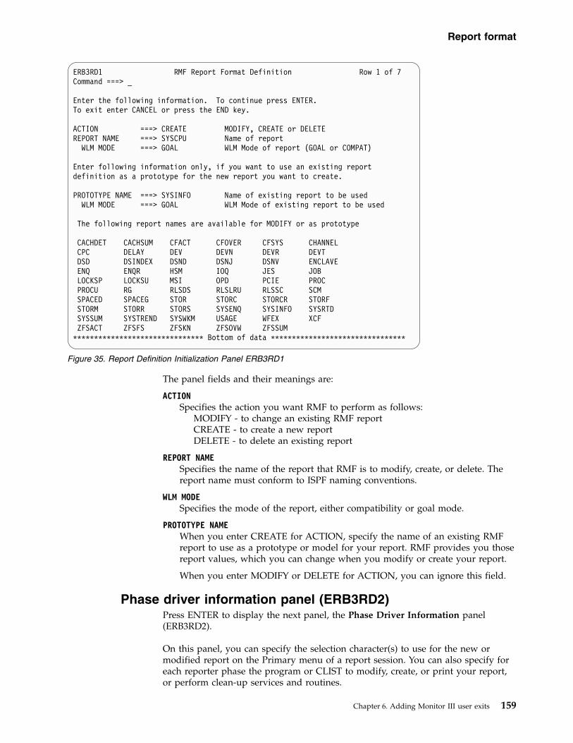
The panel fields and their meanings are:
ACTION Specifies the action you want RMF to perform as follows:
MODIFY - to change an existing RMF reportCREATE - to create a new reportDELETE - to delete an existing report
REPORT NAME Specifies the name of the report that RMF is to modify, create, or delete. Thereport name must conform to ISPF naming conventions.
WLM MODE Specifies the mode of the report, either compatibility or goal mode.
PROTOTYPE NAME When you enter CREATE for ACTION, specify the name of an existing RMFreport to use as a prototype or model for your report. RMF provides you thosereport values, which you can change when you modify or create your report.
When you enter MODIFY or DELETE for ACTION, you can ignore this field.
Phase driver information panel (ERB3RD2)Press ENTER to display the next panel, the Phase Driver Information panel(ERB3RD2).
On this panel, you can specify the selection character(s) to use for the new ormodified report on the Primary menu of a report session. You can also specify foreach reporter phase the program or CLIST to modify, create, or print your report,or perform clean-up services and routines.
ERB3RD1 RMF Report Format Definition Row 1 of 7Command ===> _
Enter the following information. To continue press ENTER.To exit enter CANCEL or press the END key.
ACTION ===> CREATE MODIFY, CREATE or DELETEREPORT NAME ===> SYSCPU Name of report
WLM MODE ===> GOAL WLM Mode of report (GOAL or COMPAT)
Enter following information only, if you want to use an existing reportdefinition as a prototype for the new report you want to create.
PROTOTYPE NAME ===> SYSINFO Name of existing report to be usedWLM MODE ===> GOAL WLM Mode of existing report to be used
The following report names are available for MODIFY or as prototype
CACHDET CACHSUM CFACT CFOVER CFSYS CHANNELCPC DELAY DEV DEVN DEVR DEVTDSD DSINDEX DSND DSNJ DSNV ENCLAVEENQ ENQR HSM IOQ JES JOBLOCKSP LOCKSU MSI OPD PCIE PROCPROCU RG RLSDS RLSLRU RLSSC SCMSPACED SPACEG STOR STORC STORCR STORFSTORM STORR STORS SYSENQ SYSINFO SYSRTDSYSSUM SYSTREND SYSWKM USAGE WFEX XCFZFSACT ZFSFS ZFSKN ZFSOVW ZFSSUM
******************************* Bottom of data ********************************
Figure 35. Report Definition Initialization Panel ERB3RD1
Report format
Chapter 6. Adding Monitor III user exits 159

If you want to modify an existing RMF report without changing the layout orheader information, you can provide your own program or CLIST for phase 2 onthis panel. You can use ISPF services and commands like TBSORT, TBDELETE, orTBCREATE to perform these modifications during phase 2.
If you want to modify an existing RMF report format or layout without adding ordeleting lines from a report, you can specify the name of the RMF report you wantto modify for phase 1 (optionally for phase 2) and the name of the standardprogram that RMF uses to format RMF reports for phase 3. See PHASE 3 STRINGin Figure 36. You can then use the remaining report format definition utility panelsto make the header and layout changes for the modified report.
If you want to create a report, you should use a prototype (see Figure 35 on page159 for the Report Format Definition panel) and make sure to include the reportselection on the Primary menu for the RMF report session.
Figure 36 is an example of a Phase Driver Information panel that containsinformation about the SYSINFO report. It assumes that the new SYSCPU reportwill become available as option 4 in the User Selection menu.
The panel fields and their meanings are as follows:
SELECTION CHARACTERS Specifies a 1 to 8 character alphanumeric value that RMF uses as a selectionvalue on the Primary menu of a report session. You must have defined theseselection characters in the menu panel.
If you enter a selection that is currently used on the Primary menu of a reportsession, RMF displays the report that you modify or create on this panel whenyou make the selection.
PHASE 1 SELECT STRING Specifies the name of the program or CLIST that the reporter control module(ERB3RDPC) uses to generate the ISPF report table during phase 1. You mustspecify a CLIST for CMD or program for PGM. (Follow the rules for ISPF
ERB3RD2 RMF Report Format DefinitionCommand ===>
Report Name: SYSCPU Section 1: Phase Driver InformationWLM Mode: GOAL
Definitions on this panel are independent of WLM mode.
Enter the following information. To continue press ENTER.To quit enter CANCEL. To go backwards press END.
Select Strings format is: PGM(nnnnnnnn) PARM(mmm) or CMD(nnnnnnnn mmm)
SELECTION CHARACTERS ===> U.4 Selection on Primary Option Panel
PHASE 1 SELECT STRING ===> PGM(ERB3RPH1) PARM(SYSINFO)TABLE NAME ===> ERBSYST3 Name of reporter phase 1 result table
PHASE 2 SELECT STRING ===>TABLE NAME ===> ERBSYST3 Optional name of phase 2 result table
PHASE 3 SELECT STRING ===> PGM(ERB3RDSP)
PHASE 4 SELECT STRING ===>
Figure 36. Phase Driver Information Panel (ERB3RD2)
Phase driver
160 z/OS RMF Programmer's Guide

SELECT services.) If you are modifying an existing RMF report or creating anew report using a prototype, you must specify for PGM the program nameERBRPH1, and for PARM the command name of the RMF report that you aremodifying or using as a prototype. If you are creating a new report, be sure toinclude the report as a selection on the Primary menu or on the User Selectionmenu.
See the RMF supplied phase driver table (ERBPHDS3) in Chapter 8, “MonitorIII data reporter tables,” on page 261 for a list of the RMF program and PARMnames.
PHASE 1 TABLE NAME Specifies the name of the ISPF table that results when your program or CLISTis invoked during phase 1. You must specify this parameter if you havespecified PHASE 1 SELECT STRING.
For a list of the RMF report data tables (PHDRTAB1) in the RMF suppliedphase driver table (ERBPHDS3), see Chapter 8, “Monitor III data reportertables,” on page 261.
PHASE 2 SELECT STRING Specifies the name of the program or CLIST used to modify the ISPF reportdata table created in phase 1. If you are creating a new report without havingspecified a prototype, you must enter the name of your CLIST to create thenew report. (Follow the rules for ISPF SELECT services.) If you are modifyingonly the report header or layout of an existing RMF report, you do not need toenter a PHASE 2 SELECT STRING.
PHASE 2 TABLE NAME Specifies the name of the ISPF table that results after phase 2. If you haveentered a value for PHASE 2 SELECT STRING, you must specify a valid phase2 table name.
If you are modifying the report header or layout of an existing RMF report,you can enter the same name you entered for PHASE 1 TABLE NAME.
PHASE 3 SELECT STRING Specifies the program or CLIST that RMF uses to initiate phase 3 to formatyour report.
If you do not provide a program or CLIST for this field, RMF skips theremaining report format definition utility panels and displays the reportdefinition initialization panel ERB3RD1. When you invoke your report duringan RMF session, RMF does not display the report.
If you are creating a report and you want RMF to display it, specifyPGM(ERB3RDSP), the standard RMF display module.
PHASE 4 SELECT STRING Specifies the program or CLIST that ERB3RDPC uses to initiate phase 4. Thisfield is optional.
Report format information panel (ERB3RD3)If you have entered a name for PHASE 3 SELECT STRING on ERB3RD2, RMF nextdisplays the Report Format Information panel (ERB3RD3). This panel is the first ina series of panels that allows you to change the header and subheader layout of anRMF report.
Phase driver
Chapter 6. Adding Monitor III user exits 161

On this panel (ERB3RD3), you can specify tabular or graphic, or both the tabularand graphic displays for the report, the panel name of the tabular version of thereport, or specify the name of a report help panel.
Figure 37 is an example of a Report Format Information panel for the SYSINFOreport:
The panel fields and their meanings are as follows:
REPORT MODE Specifies the display mode for the report. Valid values are as follows:
TABULARGRAPHICBOTH
PANEL NAMESpecifies the name of the ISPF display panel for the tabular version of thereport when you enter TABULAR or BOTH for REPORT MODE.
For a tabular report, you must specify the name of the display panel that is tocontain the report information. RMF-supplied panel names that you can useare ERB3DSI (if you are modifying or using the DI screen as a prototype),ERB3SRR (if you are modifying or using the STORR delay report as aprototype), ERB3SYS (if you are modifying or using the SYSINFO report as aprototype), ERB3WFX (if you are modifying or using the WFEX report as aprototype), or ERB3CMN (if you are modifying or using any other report as aprototype).
If you specify the name of your own panel, make sure that the panel includesthe following information:v Output fields for 2 standard header lines (DSPHDR1 and DSPHDR2)v Output fields for up to 5 subheader lines (DSPSUBH1 - DSPSUBH5)
contained in the RMF report you want to modify
ERB3RD3 RMF Report Format DefinitionCommand ===>
Report Name: SYSCPU Section 2: Report Format InformationWLM Mode: GOAL
Enter the following information. To continue press ENTER.To quit enter CANCEL. To go backwards press END.
REPORT MODE ===> BOTH TABULAR, GRAPHIC or BOTH
PANEL NAME ===> ERB4CPU Name of tabular report panel
HELP PANEL NAME ===> ERB4CPU0 Name of HELP panel
LOGICAL LINE NUMBER ===> SYSDTLLN Name of table variableSEQUENCE NUMBER ===> SYSDTPSN Name of table variable
Figure 37. Report Format Information Panel (ERB3RD3)
Report format
162 z/OS RMF Programmer's Guide

v Output fields for up to 3 column header lines (FMTCOLH1 -FMTCOLH3)contained in the RMF report you want to modify. For a description of thereport format table ERBFMTS3, see Chapter 8, “Monitor III data reportertables,” on page 261.
v Up to 3 model line variables (FMTMODL1 - FMTMODL3) contained in themodel section of the RMF report you want to modify. For a description ofthe entries in the report format table ERBFMTS3, see Chapter 8, “Monitor IIIdata reporter tables,” on page 261.
v The command line (defined by variable ZCMD) and scroll amount field(defined by variable AMT)
Also, ensure that the user-defined panel for your report includes aninitialization (INIT), reinitialization (REINIT), and processing (PROC) section asin the RMF-supplied panels.
If you enter GRAPHIC for REPORT MODE, leave PANEL NAME blank.
HELP PANEL NAMEWhen you enter a value for PANEL NAME, specifies the name of the ISPFhelp panel that contains help information for your report. The field is optional.
LOGICAL LINE NUMBER/SEQUENCE NUMBERSpecifies the name of key variables in the data table of the RMF report you aremodifying. A logical line number identifies a logical group of related data rowswithin a report; a line sequence number identifies each physical table row thatbelongs to the logical group.
The logical line number (that identifies the entire data group) is 1; thesequence number (the number of physical lines that belong to the logical groupand include the volume serial/device type on one line and the space type onthe second line of the graphic report) is 2 or more.
When you toggle between tabular and graphic reports, RMF uses thesevariables to synchronize the line or bar displayed on the screen (the beginningof a logical group of data table rows). For examples of RMF report data tables,see Chapter 8, “Monitor III data reporter tables,” on page 261.
Report header layout panels (ERB3RD4 and ERB3RD5)Press ENTER to display the next panel, ERB3RD4, the Report Header Layoutpanel.
Each RMF report contains report headings, subheadings, and columns that you canmodify. The Report Header Layout panels (ERB3RD4 and ERB3RD5) allow you tochange up to 2 header lines for the tabular and graphic versions of the report.
On the first of these panels (ERB3RD4), you can specify the header lines andheader variables for your report. At the bottom of the panel, enter the header linesexactly as you want them to appear on your report. You can use the variableslisted on the panel to appear in the headings of your report. (Panel ERB3RD4 listsvariables from header data table ERBHDRS3. For the meaning of all variables inERBHDRS3, see Chapter 8, “Monitor III data reporter tables,” on page 261.)
If a variable name is too long to enter in the header line, you can use a placeholder(&Z). After you press ENTER, you define these placeholders with variable nameson the next panel.
Figure 38 on page 164 is an example of a report format definition panel ERB3RD4that shows you the headings and variables for the SYSINFO report with the
Report format
Chapter 6. Adding Monitor III user exits 163

modified report title CPU Information:
In Figure 38, two report header lines appear at the bottom of the panel and tenvariable names are available for the header lines.v Variables &ERBHCTXT and &ERBRMFVD are specified at the beginning of the
first header line.v Variables &ERBDATE and &ERBTIME are specified for Date and Time.v Placeholders (&Z) for the other variables (&ERBSID for session id, &ERBSAMPL
for samples, and &ERBRANGE for range) appear in the appropriate fields of theheader lines and indicate that the variable names they represent might not fit inthe space provided. These placeholders can be defined on the next panel.
Press ENTER to display the second Report Header Layout panel (ERB3RD5).
On ERB3RD5, you can specify variable names for any Z placeholders you haveused. The headings, variables names, and placeholders as you entered them onERB3RD4 appear at the top of the panel. The variable names appear under theheadings in the order specified on ERB3RD4. You can specify your own variablenames in the spaces provided; however, in order for RMF to display theuser-specified variables during a report session, they must be in the function poolfor phase 3 or in the shared ISPF variable pool. Otherwise, blanks appear in thereport. See “Installing your own phases” on page 178.
You must specify a number for each Z placeholder and its corresponding variable.Numbers must start with 1 and continue in sequence. There must be a one-to-onecorrespondence between placeholders and variable names, each pair with a uniquenumber assigned to indicate the order of placement of the variable.
Figure 39 on page 165 is an example of Report Header Layout panel ERB3RD5 thatdefines the placeholders used on the previous panel. If you do not haveplaceholders to define, press ENTER to get the next panel.
ERB3RD4 RMF Report Format DefinitionCommand ===>
Report Name: SYSCPU WLM Mode: GOAL Section 3: Report Header Layout
Enter or change the report header lines. To continue press ENTER.To quit enter CANCEL. To go backwards press END.
You may intermix: text, variables, and variable placeholders (&Z).If you specify variable placeholders (&Z) the next panel will ask youto specify the variable name that is to replace each &Z
The following variables are available for use in the header:&ERBSID &ERBSAMPL &ERBTIME &ERBRMFVD &ERBSNUM&ERBHCTXT &ERBDATE &ERBRANGE &ERBSPXID &ERBSAMWL
Variables ERBSID, ERBDATE, ERBTIME and ERBRANGE will be supported as inputfields only, if they are part of second header line.
Enter or change up to two report heading lines:
&ERBHCTXT &ERBRMFVD CPU InformationSamples: &Z System: &Z Date: &ERBDATE Time: &ERBTIME Range: &Z Sec
Figure 38. Report Header Layout Panel (ERB3RD4)
Header layout
164 z/OS RMF Programmer's Guide

v Variable &ERBSAMPL that contains the number of samples replaces Z1.v Variable &ERBSID that contains the session id replaces Z2 in the first header line
of the report.v &ERBRANGE that contains the range value replaces Z3 in the second header
line.
Depending on your selection on panel ERB3RD3, you will continue as follows:v If you specified TABULAR or BOTH for report mode, RMF displays the Report
Subheader Layout panel ERB3RD6.v If you specified GRAPHIC for report mode, RMF displays the Graphic
Parameter Definition panel ERB3RDB, see “Graphic parameter definition panels(ERB3RDB, ERB3RDC, ERB3RDD)” on page 170.
Report subheader layout panels (ERB3RD6 and ERB3RD7)The Report Subheader Layout panel (ERB3RD6) displays up to five subheader linesof an existing RMF report. (Subheader lines are any lines in an RMF report thatappear between the two standard header lines and the column headings.)ERB3RD6 also lists the variables that are available for use in the subheader lines ofthe modified report.
At the bottom of ERB3RD6, you enter the subheader lines exactly as you wantthem to appear on your report. You can use the variables listed on the panel toappear in the subheadings of your report. Panel ERB3RD6 lists variables fromheader data table ERBHDRS3.
If a variable name is too long to appear in the header line, you can use aplaceholder (&Z). After you press ENTER, you define these placeholders withvariable names on the next panel.
Figure 40 on page 166 is an example of a Report Subheader Layout panel ERB3RD6that shows the subheadings of the SYSINFO report.
ERB3RD5 RMF Report Format DefinitionCommand ===>
Report Name: SYSCPU Section 3: Report Header LayoutWLM Mode: GOAL
The following report header lines have been specified:&ERBHCTXT &ERBRMFVD CPU Information
Samples: Z1 System: Z2 Date: &ERBDATE Time: &ERBTIME Range: Z3 Sec
Specify the placeholder (Z) number next to the variable name to replace each Zabove.To continue press ENTER.To go backwards press END.To quit enter CANCEL.
&ERBSID ===> 2 &ERBHCTXT ===> __ &ERBSAMPL ===> 1&ERBDATE ===> __ &ERBTIME ===> __ &ERBRANGE ===> 3&ERBRMFVD ===> __ &ERBSPXID ===> __ &ERBSNUM ===> __&ERBSAMWL ===> __ ===> _________ ===> __ ===> _________ ===> __
===> _________ ===> __ ===> _________ ===> __ ===> _________ ===> __
Figure 39. Report Header Layout Panel (ERB3RD5)
Header layout
Chapter 6. Adding Monitor III user exits 165

In Figure 40, subheader lines appear at the bottom of the panel and 24 variablenames from the SYSINFO report are available. You can modify these subheaderlines and indicate where you want the available variables to appear in them.
Press ENTER to display the next panel ERB3RD7, the second Report SubheaderLayout panel.
On this panel, you can specify variable names for any Z placeholders you haveused. For a description of how to replace placeholders with variable names, see theReport Header Layout panel ( Figure 39 on page 165).
Figure 41 on page 167 shows panel ERB3RD7 that defines placeholders used on theprevious panel.
ERB3RD6 RMF Report Format DefinitionCommand ===>
Report Name: SYSINFO WLM Mode: GOAL Section 4: Report Subheader Layout
Enter or change the report subheader lines. To continue press ENTER.To quit enter CANCEL. To go backwards press END.
You may intermix: text, variables, and variable placeholders (&Z).If you specify variable placeholders (&Z) the next panel will ask youto specify the variable name that is to replace each &Z.
The following variables are available for use in the subheader:&SYSPARVC &SYSMODVC &SYSMDLVC &SYSTSVVC &SYSIPVVC &SYSPOLVC&SYSVEPVC &SYSPRVVC &SYSCUVVC &SYSTSEVC &SYSOPVVC &SYSPADVC&SYSPRIVC &SYSICVVC &SYSLCPVC &SYSAPIVC &SYSPATVC &SYSPRTVC&SYSAPTVC &SYSAICVC &SYSATCVC &SYSLOAVG &SYSTCTVC &SYSUTCVC
Enter or change up to five report subheading lines:&Z &Z Model &Z Appl%: &Z Policy: &ZCPs Online: &Z Avg CPU Util%: &Z EAppl%: &Z Date: &ZAAPs Online: &Z &Z Appl% AAP: &Z Time: &ZIIPs Online: &Z Appl% IIP: &Z
Figure 40. Report Subheader Layout Panel (ERB3RD6)
Subheader layout
166 z/OS RMF Programmer's Guide

Report column layout panels (ERB3RD8 and ERB3RD9)Press ENTER to display the next panel, ERB3RD8, the report subheader firstReport Column Layout panel.
On this panel, you can modify report columns. You can enter up to three columnheader lines as you want them to appear in the report.
You can specify up to three model lines for your columns by using an attributecharacter followed by a variable name or placeholder (&Z). (See DATAATTRIBUTE CHARACTERS described below.)
You can use the variable names listed at the bottom of the panel to appear in thecolumns of your report. This panel also allows you to specify a placeholder (&Z)for any variable name you want to use. (Panel ERB3RD8 lists variables from thedata table of the RMF report you are modifying. All variables might not appear onthe first page of the panel. Scroll through the panel and select the variable namesyou need. For information about RMF report data tables, see Chapter 8, “MonitorIII data reporter tables,” on page 261.) You can define placeholders for variablenames on the next panel.
Figure 42 on page 168 is an example of ERB3RD8 that shows report columnheadings for the modified SYSINFO report with columns that contain data aboutTCB%, SRB%, and execution velocity. The details about delay percentages havebeen removed.
ERB3RD7 RMF Report Format DefinitionCommand ===>
Report Name: SYSINFO WLM Mode: GOAL Section 4: Report Subheader Layout
The following report subheader lines have been specified:Z1 Z2 Model Z3 Appl%: Z4 Policy: Z5CPs Online: Z6 Avg CPU Util%: Z7 EAppl%: Z8 Date: Z9AAPs Online: Z10 Z11 Appl% AAP: Z12 Time: Z13IIPs Online: Z14 Appl% IIP: Z15
Specify the placeholder (Z) number next to the variable name to replace each Zabove. To continue press ENTER. To go backwards press END.To quit enter CANCEL.
&SYSPARVC ===> 1 &SYSMODVC ===> 2 &SYSMDLVC ===> 3&SYSTSVVC ===> 4 &SYSIPVVC ===> __ &SYSPOLVC ===> 5&SYSVEPVC ===> __ &SYSPRVVC ===> 6 &SYSCUVVC ===> 7&SYSTSEVC ===> 8 &SYSOPVVC ===> __ &SYSPADVC ===> 9&SYSPRIVC ===> 10 &SYSICVVC ===> __ &SYSLCPVC ===> 11&SYSAPIVC ===> 12 &SYSPATVC ===> 13 &SYSPRTVC ===> 14&SYSAPTVC ===> 15 &SYSAICVC ===> __ &SYSATCVC ===> __&SYSLOAVG ===> __ &SYSTCTVC ===> __ &SYSUTCVC ===> __
Figure 41. Report Subheader Layout Panel (fERB3RD7)
Column layout
Chapter 6. Adding Monitor III user exits 167

DATA ATTRIBUTE CHARACTERS Specifies the ISPF characters used to indicate the start of a data field. Specifythe data attribute characters before each variable name or placeholder (&Z)used in the model lines.
You must specify the name of a panel for the tabular version of a new ormodified report. For RMF-supplied panels, the attribute characters appear asfollows:v a question mark (?) indicates that the output display characters appear
unhighlighted (low intensity) in turquoisev a slash (|) indicates that the output display characters appear highlighted
(high intensity) in whitev a blank indicates that the input display characters appear unhighlighted
(high intensity) in green
For user-defined panels, be sure that the data attribute characters match thecharacters in the attribute section of your ISPF display panel. See PANELNAME on the report format information panel (ERB3RD3).
Press ENTER to display the next panel ERB3RD9, the second Report ColumnLayout panel.
On this panel, you can specify variable names for any Z placeholders you haveused. The variable names available on the previous panel are listed at the bottom;you can add your own variable names in the spaces provided. If your variablenames are not available when you invoke the report, blanks will appear instead of
ERB3RD8 RMF Report Format Definition Line 1 of 10Command ===> Scroll ===> PAGE
Report Name: SYSINFO Section 5: Report Column LayoutWLM Mode: GOAL
Enter or change the following information. To continue press ENTER.To quit enter CANCEL. To go backwards press END.
DATA ATTRIBUTE CHARACTERS ===> _?| Define meaning in attribute sectionof associated table display (ERB3SYS).
Enter or change up to three column header lines:Group T WFL --Users-- RESP TRANS CPU TCB SRB -AVG USG- -Avg Del-
% TOT ACT Time /SEC % % % PROC DEV PROC DEV_____________________________________________________________________________
Enter or change up to three model lines:?Z ?Z?Z ?Z ?Z ?Z ?Z ?Z ?Z ?Z ?Z ?Z ?Z ?Z
______________________________________________________________________________________________________________________________________________________________
The following variables are available for use in the model lines:SYSNAMVC SYSTYPVC SYSWFLVC SYSTUSVC SYSAUSVC SYSTRSVCSYSAFCVC SYSVECVC SYSAUPVC SYSAUDVC SYSADPVC SYSADDVCSYSADSVC SYSADUVC SYSADOVC SYSADEVC SYSADJVC SYSADHVCSYSADXVC SYSADNVC SYSADMVC SYSCPUVC SYSSRBVC SYSTCBVCSYSIFAVC SYSCPVC SYSIFCVC SYSRSPVC SYSVELVC SYSUGMVCSYSUGPVC SYSUGDVC SYSWGDVC SYSWGPVC SYSDGMVC SYSUJMVCSYSDJMVC SYSDGEVC SYSDGHVC SYSDGDVC SYSDGJVC SYSDGOVCSYSDDSIP SYSEAPVC SYSLPIVC SYSSUPVC SYSSUCVC SYSDTLLN
Figure 42. Report Column Layout Panel (ERB3RD8)
Column layout
168 z/OS RMF Programmer's Guide

data. See the report header information panel (ERB3RD5) in Figure 39 on page 165for a description of how to replace placeholders with variable names.
If not all variable names appear on the first page of the panel, scroll through theremaining pages of the panel to see all available variable names.
Figure 43 is an example of Report Column Layout panel ERB3RD9 that definesplaceholders used on the previous panel.
Command line layout panel (ERB3RDA)Press ENTER to display the next panel ERB3RDA, the Command Line Layoutpanel.
On this panel, you can specify the format of the command line and scroll line asyou want them to appear on the hardcopy of the tabular report. You must alsodefine the command line and scroll line on the display panel of the tabular report.
Figure 44 on page 170 is an example of Command Line Layout panel ERB3RDA.
ERB3RD9 RMF Report Format Definition Line 1 of 21Command ===> Scroll ===> PAGE
Report Name: SYSINFO Section 5: Report Column LayoutWLM Mode: GOAL
The following report column header and model lines have been specified:Group T WFL --Users-- RESP TRANS CPU TCB SRB -AVG USG- -Avg Del-
% TOT ACT Time /SEC % % % PROC DEV PROC DEV
Z1 Z2Z3 Z4 Z5 Z6 Z7 Z8 Z9 Z10 Z11 Z12 Z13 Z14
Specify the placeholder (Z) number next to the variable name to replace each Zabove. To continue press ENTER. To go backwards press END.To quit enter CANCEL.
SYSNAMVC ===> 1 SYSTYPVC ===> 2 SYSWFLVC ===> 3SYSTUSVC ===> 4 SYSAUSVC ===> 5 SYSRSPVC ===> 6SYSTRSVC ===> 7 SYSCPUVC ===> 8 SYSTCBVC ===> 9SYSSRBVC ===> 10 SYSAUPVC ===> 11 SYSAUDVC ===> 12SYSADPVC ===> 13 SYSADDVC ===> 14 SYSAFCVC ===> __SYSVECVC ===> __ SYSADSVC ===> __ SYSADUVC ===> __SYSADOVC ===> __ SYSADEVC ===> __ SYSADJVC ===> __SYSADHVC ===> __ SYSADXVC ===> __ SYSADNVC ===> __SYSADMVC ===> __ SYSIFAVC ===> __ SYSCPVC ===> __SYSIFCVC ===> __ SYSVELVC ===> __ SYSUGMVC ===> __SYSUGPVC ===> __ SYSUGDVC ===> __ SYSWGDVC ===> __SYSWGPVC ===> __ SYSDGMVC ===> __ SYSUJMVC ===> __SYSDJMVC ===> __ SYSDGEVC ===> __ SYSDGHVC ===> __SYSDGDVC ===> __ SYSDGJVC ===> __ SYSDGOVC ===> __SYSDGPVC ===> __ SYSDGSVC ===> __ SYSDGUVC ===> __
Figure 43. Report Column Layout Panel (ERB3RD9)
Column layout
Chapter 6. Adding Monitor III user exits 169

Graphic parameter definition panels (ERB3RDB, ERB3RDC,ERB3RDD)
If you specified BOTH or GRAPHIC for report mode on ERB3RD3, RMF displaysthe first Graphic Parameter Definition panel, ERB3RDB.
On this panel, you can specify general information about the graphic version of thereport.
Note: If you specified TABULAR for report mode on the report format informationpanel (ERB3RD1) or used DI or WFEX as a prototype, the report format definitionutility displays panel ERB3RDF. This panel allows you to save your changes andview the tabular report you have created or cancel your changes. See “Saving orcancelling changes on panel ERB3RDF” on page 174.
Figure 45 on page 171 is an example of the Graphic Parameter Definition panelERB3RDB that specifies general information for the graphic version of theSYSINFO report:
ERB3RDA RMF Report Format DefinitionCommand ===>
Report Name: SYSCPU WLM Mode: GOAL Section 6: Command Line Layout
Enter or change the following information. To continue press ENTER.To quit enter CANCEL. To go backwards press END.
You may intermix: text, variables, and variable placeholders (&Z).
The following variables are available for use in the command line:&ZCMD &AMT
Enter or change the command line:
Command ===>
Specify a variable name in each of the entry fields to replace each Z above.
Z1 ===>Z2 ===>Z3 ===>
Figure 44. Command Line Layout Panel (ERB3RDA)
Graphic panels
170 z/OS RMF Programmer's Guide
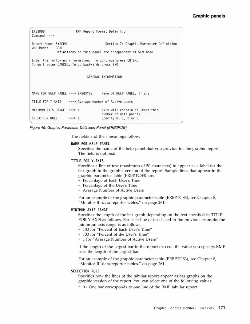
The fields and their meanings follow:
NAME FOR HELP PANELSpecifies the name of the help panel that you provide for the graphic report.The field is optional.
TITLE FOR Y-AXISSpecifies a line of text (maximum of 50 characters) to appear as a label for thebar graph in the graphic version of the report. Sample lines that appear in thegraphic parameter table (ERBPTGS3) are:v Percentage of Each User's Timev Percentage of the User's Timev Average Number of Active Users
For an example of the graphic parameter table (ERBPTGS3), see Chapter 8,“Monitor III data reporter tables,” on page 261.
MINIMUM AXIS RANGESpecifies the length of the bar graph depending on the text specified in TITLEFOR Y-AXIS as follows. For each line of text listed in the previous example, theminimum axis range is as follows:v 100 for “Percent of Each User's Time”v 100 for “Percent of the User's Time”v 1 for “Average Number of Active Users”
If the length of the largest bar in the report exceeds the value you specify, RMFuses the length of the largest bar.
For an example of the graphic parameter table (ERBPTGS3), see Chapter 8,“Monitor III data reporter tables,” on page 261.
SELECTION RULE Specifies how the lines of the tabular report appear as bar graphs on thegraphic version of the report. You can select one of the following values:v 0 - One bar corresponds to one line of the RMF tabular report
ERB3RDB RMF Report Format DefinitionCommand ===>
Report Name: SYSCPU Section 7: Graphic Parameter DefinitionWLM Mode: GOAL
Definitions on this panel are independent of WLM mode.
Enter the following information. To continue press ENTER.To quit enter CANCEL. To go backwards press END.
GENERAL INFORMATION
NAME FOR HELP PANEL ===> ERBGSYS0 Name of HELP PANEL, if any
TITLE FOR Y-AXIS ===> Average Number of Active Users
MINIMUM AXIS RANGE ===> 1 Axis will contain at least thisnumber of data points
SELECTION RULE ===> 1 Specify 0, 1, 2 or 3
Figure 45. Graphic Parameter Definition Panel (ERB3RDB)
Graphic panels
Chapter 6. Adding Monitor III user exits 171

v 1 - One bar corresponds to one line of the RMF tabular report with sequencenumber 1 (for example, DEV, HSM, JES, STOR, PROC, DELAY, SYSINFO,and ENQ)
v 2 - One bar corresponds to the summary of logical lines of the report (forexample, ENQR, DEVR reports)
v 3 - Two bar types can result from all logical lines of a logical block in theRMF tabular report (for example, STORR report) as follows:– Bar type 1 corresponds to a line of the tabular report with sequence
number 1– Bar type 2 corresponds to each additional line of the logical block for a
tabular report with a sequence number greater than 1
For an example of the graphic parameter table (ERBPTGS3), see Chapter 8,“Monitor III data reporter tables,” on page 261. For a description of logical linenumber and sequence number, see the panel field description for ERB3RD3 (Figure 37 on page 162).
Press ENTER to display the next panel, ERB3RDC, the second Graphic ParameterDefinition panel.
On this panel, you can specify labels for the graphic bars in the report. You canspecify variable names for bar type 1 labels and bar type 2 labels.
Figure 46 is an example of the Graphic Parameter Definition panel ERB3RDC.
The panel fields and their meanings are as follows:
PRIMARY LABEL/SECONDARY LABELSpecifies an 8 character variable name for a data value in the graphic versionof the report. You can use the variable names that appear in the ISPF data tableof the corresponding tabular report.
ERB3RDC RMF Report Format DefinitionCommand ===>
Report Name: SYSCPU Section 7: Graphic Parameter DefinitionWLM Mode: GOAL
Definitions on this panel are independent of WLM mode.
Enter the following information. To continue press ENTER.To quit enter CANCEL. To go backwards press END.
LABEL INFORMATION FOR BAR TYPE I
PRIMARY LABEL ===> SYSNAMVC Variable name containing labelSECONDARY LABEL ===> ________ Variable name containing labelPRIMARY COMPOSITE ===> _____ Prefix of labelSECONDARY COMPOSITE ===> _____ Prefix of label
LABEL INFORMATION FOR BAR TYPE II
PRIMARY LABEL ===> ________ Variable name containing labelSECONDARY LABEL ===> ________ Variable name containing labelPRIMARY COMPOSITE ===> _____ Prefix of labelSECONDARY COMPOSITE ===> _____ Prefix of label
Figure 46. Graphic Parameter Definition Panel (ERB3RDC)
Graphic panels
172 z/OS RMF Programmer's Guide

For example, in Figure 46 on page 172, the Primary label will appear asaverage number of active users (SYSNAMVC) on the graphic version of theSYSCPU report.
See Chapter 8, “Monitor III data reporter tables,” on page 261 for examples ofthe Graphic Parameter table (ERBPTGS3) and the RMF Report Data tables.
PRIMARY COMPOSITE/SECONDARY COMPOSITE Specifies up to 5 characters of text as a prefix to the variable label specified inPRIMARY/SECONDARY LABEL. In Figure 46 on page 172, no compositelabels appear in the SYSCPU report. You can specify a prefix to appear in thegraphic version of the report. The prefix is concatenated to the rightmostcontents of the report table variable specified in PRIMARY/SECONDARYlabel.
See Chapter 8, “Monitor III data reporter tables,” on page 261 for examples ofthe Graphic Parameter table (ERBPTGS3) and the RMF Report Data tables.
BAR TYPE refers to the number of bars used in the report depending on thelogical line and sequence numbers.
See LOGICAL LINE/SEQUENCE NUMBER in the field descriptions forERB3RD3 ( Figure 37 on page 162).
Press ENTER to display the next panel, ERB3RDD, the third Graphic ParameterDefinition panel.
On this panel, you can specify data columns that you want to appear in thegraphic version of the report.
Figure 47 is an example of the Graphic Parameter Definition panel ERB3RDD.
The panel fields and their meanings are as follows:
ERB3RDD RMF Report Format DefinitionCommand ===>
Report Name: SYSCPU Section 7: Graphic Parameter DefinitionWLM Mode: GOAL
Definitions on this panel are independent of WLM mode.
Enter the following information. To continue press ENTER.To quit enter CANCEL. To go backwards press END.
COLUMN SPECIFICATION FOR GRAPHIC BAR TYPES
NAME LEGEND ID TRANS ID BAR TYPE ID
1. ===> SYSADPVC ===> 14 ===> 0 ===> 12. ===> SYSADDVC ===> 08 ===> 0 ===> 13. ===> SYSADSVC ===> 15 ===> 0 ===> 14. ===> SYSADUVC ===> 28 ===> 0 ===> 15. ===> SYSADOVC ===> 29 ===> 0 ===> 16. ===> SYSADEVC ===> 09 ===> 0 ===> 17. ===> SYSAUPVC ===> 19 ===> 0 ===> 18. ===> SYSAUDVC ===> 18 ===> 0 ===> 19. ===> ________ ===> __ ===> _ ===> _
10. ===> ________ ===> __ ===> _ ===> _
Figure 47. Graphic Parameter Definition Panel (ERB3RDD)
Graphic panels
Chapter 6. Adding Monitor III user exits 173

NAMESpecifies an 8 character variable name for a data value from the correspondingtabular report. This value will appear as a bar column in the graphic version ofthe report. The bar column can be a single bar (bar type 1) or a stacked bar(bar type 2) depending on what you specify for BARTYPE ID. See Chapter 8,“Monitor III data reporter tables,” on page 261 for examples of RMF reportdata tables.
LEGEND IDSpecifies a number that corresponds to the color, pattern and the text of thegraphic chart legend. Variables specified for NAME will appear in the colorspecified for LEGEND ID. You can specify a decimal value from 04 to 27; thenumbers must match the color ID entries on the Color Graphic Option panels.
TRANS ID Specifies a number that controls how the values for the variable in NAME arescaled on the bar graph in the graphic version of the report.v 0 - value appears as is; no division is performedv n - value is divided by 10n where n equals an integer from 1 to 9.
See Chapter 8, “Monitor III data reporter tables,” on page 261 for examples ofRMF report data tables.
BARTYPE ID Specifies a value that indicates where the data value for the variable in NAMEappears for bar types in the graphic version of the report:v 0 - indicates the value appears in both bar typesv 1 - indicates the value occurs in bar type 1v 2 - indicates the value occurs in bar type 2
If you specified label information for only bar type 1 on the report parameterdefinition panel (ERB3RDC), you must specify bar type 1.
Saving or cancelling changes on panel ERB3RDFOnce you have created or modified a report using the report format definitionutility panels, RMF displays panel ERB3RDF, which allows you to confirm orcancel your changes.
ERB3RDF RMF Report Format DefinitionCommand ===>
This is a confirmation/cancellation panel for report: SYSCPUrelated with WLM mode: GOAL
The following actions are allowed:
Type SAVE command to save report
Type CANCEL command to cancel processing
Press END key to go one step backwards
Press ENTER key to see the sample report
Figure 48. Configuration/Cancellation Panel (ERB3RDF)
Graphic panels
174 z/OS RMF Programmer's Guide

You can get a report with sample data just to verify the correct layout of thereport. In this example, some values are not displayed because they are not part ofthe sample data.
The report shows that adjustments for some columns are necessary. You can dothis either by stepping back to panel ERB3RD8 before you save the report or bymodifying the stored report.
Enter SAVE to save the report or CANCEL to cancel your changes and return tothe report definition initialization panel (ERB3RD1). If you save the report, RMFredisplays panel ERB3RD1 with a message that tells you the report has beenmodified or created. To exit the sample report panel and return to panel ERB3RDF,press END.
Deleting a user-defined reportIf you specify DELETE for a report on the report format definition panel, RMFdisplays panel ERB3RDE. To confirm the deletion of the report, press ENTER andthe report is deleted. To cancel the deletion, type CANCEL and press ENTER. RMFreturns you to ERB3RD1.
Note: You can only delete a user-defined report. RMF does not allow you to deletean existing RMF report.
ERB4CPU RMF V2R3 CPU Information Line 1 of 20Command ===> Scroll ===> PAGE
Samples: 60 System: SYSE Date: 06/08/2015 Time: 08.59.00 Range: 60Sec
Partition: SYSE 2084 Model 314 Appl% : 22 Policy: STANDARDCPs Online: 4.0 Avg CPU Util%: 24 EAppl%: 22 Date: 05/12/05AAPs Online: 1.0 Avg MVS Util%: 26 Appl% AAP: 19 Time: 12.20.27IIPs Online: - Appl% IIP: -
Group T WFL --Users-- RESP TRANS CPU TCB SRB -AVG USG- -Avg Del-% TOT ACT Time /SEC % % % PROC DEV PROC DEV
*SYSTEM 98 167 2 0.12 21.6 21.5 0.2 1.6 0.1 0.0 0.0*TSO 3 0 0.12 0.0 0.0 0.0 0.0 0.0 0.0 0.0*BATCH 99 3 2 0.00 20.5 20.5 0.0 1.5 0.0 0.0 0.0*STC 91 158 0 0.00 1.2 1.0 0.2 0.1 0.1 0.0 0.0*ASCH 0 0 0.00 0.0 0.0 0.0 0.0 0.0 0.0 0.0*OMVS 3 0 0.00 0.0 0.0 0.0 0.0 0.0 0.0 0.0*ENCLAVE 0 N/A N/A N/A N/A N/A 0.0 N/A 0.0 N/ABATCH W 99 4 2 .000 0.00 20.5 20.5 0.0 1.5 0.0 0.0 0.0BATCHLOW S 99 3 2 .000 0.00 20.5 20.5 0.0 1.5 0.0 0.0 0.0OMVSKERN S 1 0 .000 0.00 0.0 0.0 0.0 0.0 0.0 0.0 0.0OMVS W 2 0 .000 0.00 0.0 0.0 0.0 0.0 0.0 0.0 0.0OE S 2 0 .000 0.00 0.0 0.0 0.0 0.0 0.0 0.0 0.0STC W 100 26 0 .000 0.00 0.1 0.1 0.0 0.0 0.0 0.0 0.0STCDEF S 100 26 0 .000 0.00 0.1 0.1 0.0 0.0 0.0 0.0 0.0SYSTEM W 90 132 0 .000 0.00 1.0 0.9 0.2 0.1 0.1 0.0 0.0SYSSTC S 100 111 0 .000 0.00 0.3 0.3 0.0 0.0 0.0 0.0 0.0SYSTEM S 88 21 0 .000 0.00 0.7 0.6 0.2 0.1 0.1 0.0 0.0TSO W 3 0 .010 0.17 0.0 0.0 0.0 0.0 0.0 0.0 0.0TSODEF S 3 0 .010 0.17 0.0 0.0 0.0 0.0 0.0 0.0 0.0BCP R 99 3 2 .000 0.00 20.5 20.5 0.0 1.5 0.0 0.0 0.0
Figure 49. Initial Version of the SYSCPU Report
Ending Mon III utility
Chapter 6. Adding Monitor III user exits 175

Ending the report utilityYou can end the report format definition utility session by pressing END (PF3) onthe report format definition panel (ERB3RD1) or by specifying CANCEL on anypanel.
Implementing the reportTo make the new SYSCPU report available, it needs to be integrated in a MonitorIII selection panel. As defined initially, the report shall be added to the UserSelection menu ERB3USR. You can do this by these modifications to the definitionof the panel:
)attr default(!+_)/***********************************************************************/* PANEL NAME: ERB3USR/*
...
)body expand("") cmd(zcmd)+ ! RMF User-written Report Selection Menu " "!Selection ===>_ZCMD " " ++<Enter selection number or command for desired report.++! 1<MSI +Migration SYSINFO including Execution Velocity! 2<DSD +Detailed Storage Delays! 3<RG +Resource Group Data! ▌4<SYSCPU +Modified SYSINFO including CPU details▐+
...
Figure 50. Modifications in User Selection Menu Definition (ERB3USR) - Part 1
Ending Mon III utility
176 z/OS RMF Programmer's Guide

If you call the User Selection menu, you now get this new version:
/* translate subsystem selections ********************************* */&erbcmdc = trans(&erbcmdc
1,’MSI’2,’DSD’3,’RG’
▌4,’SYSCPU’▐ST,’SYSTREND’DA,’DEVN’DT,’DEVT’*,*)
/* Checks if command input is a valid RMF command. */ver(&erbcmdc,LIST, CANCEL, FIND, GRAPHIC, ICU, HARDCOPY, RESET,
RFIND, TABULAR, TOGGLE,MSI, DSD, RG, ▌SYSCPU,▐DEVN, DEVT, SYSTREND,MSG=ERB562I)
/* Checks if command input is a valid on this screen. */ver(&erbcmdc,LIST,;
MSI, DSD, RG, ▌SYSCPU,▐DEVN, DEVT, SYSTREND,MSG=ERB573I)
...
/* selects action according to entered input ********************** */&zsel = trans(&erbcmdc
MSI,’PGM(ERB3RDPC) PARM(MSI)’DSD,’PGM(ERB3RDPC) PARM(DSD)’RG,’PGM(ERB3RDPC) PARM(RG)’
▌SYSCPU,’PGM(ERB3RDPC) PARM(SYSCPU)’▐DEVN,’PGM(ERB3RDPC) PARM(DEVN)’DEVT,’PGM(ERB3RDPC) PARM(DEVT)’
SYSTREND,’PGM(ERB3RDPC) PARM(SYSTREND)’*,’ ’)
)END
Figure 51. Modifications in User Selection Menu Definition (ERB3USR) - Part 2
ERB3USR RMF User-written Report Selection MenuSelection ===>
Enter selection number or command for desired report.
1 MSI Migration SYSINFO including Execution Velocity2 DSD Detailed Storage Delays3 RG Resource Group Data4 SYSCPU Modified SYSINFO including CPU details
Device ReportsDA DEVN Device ActivityDT DEVT Device Trend
Device => _______
System ReportsST SYSTREND System and Workload Trend
Workload => ________
Figure 52. Modified User Selection Menu (ERB3USR)
Implementing report
Chapter 6. Adding Monitor III user exits 177

Special considerations for modifying reportsIf you want to add or delete lines in an existing RMF report or sort lines of areport without modifying the report heading, consider the following when you usethe report format definition utility:v Each RMF report data table (PHDRTAB1 in the phase driver table) contains the
ISPF key type variables for the logical line number and line sequence numberfor the report. Each data table lists the logical lines and the sequence number(s)for logical lines of data in the report in ascending order. Sequence numbers foreach logical line begin with 1. When you add, delete, or sort lines of an RMFreport, be sure that the output table of your report (PHASE 1 or 2 TABLE onphase driver information panel ERB3RD2) arranges logical line and sequencenumbers in ascending order.
v If you delete a line of a report with sequence number 1, you must also delete thelogical line number of the report from the data table.
v If you want to rearrange the lines of an RMF report, you can use the ISPFservice TBSORT as part of the CLIST you specify for phase 2. You can specifythe CLIST with TBSORT on the phase driver information panel (ERB3RD2) asfollows:CMD(mysort)
where “mysort” is the name of your CLIST.
Installing your own phasesWhen you select a report during a reporter session, RMF uses ISPF SELECTservices to generate report data tables and display the reports. You can supplyyour own routines for any of the 4 phases to produce user-defined reports. See“Data reporter phases” on page 153 for a description of the phases RMF invokes.
The following ISPF shared variables are available during all phases. They can beupdated in Phase 1 by the Data Retrieval Service.
ERBDATE,ERBTIMEThe ISPF shared pool variables that contain the beginning date and time ofthe display data.
ERBRANGEThe ISPF shared pool variable that contains the range time of the displaydata. The beginning date/time plus the range time of the display dataequals the ending date/time.
ERBSIDThe ISPF shared pool variable that contains the id of the system on whichthe data was collected.
ERBSAMPLThe ISPF shared pool variable that contains the number of data samplesfor the time range.
ERBRMFVDThe ISPF shared pool variable that contains the RMF version number ofthe data gatherer which collected the data. The format is RMF VvRr (thatis, RMF V2R3).
ERBDTBEGThe ISPF shared pool variable which contains the beginning date/timevalue for the requested time range. The format is MMDDYYYYHHMMSS(that is, 09252015183050 represents September 25, 2015 at 18:30:50).
Modifying reports
178 z/OS RMF Programmer's Guide

ERBDTENDThe ISPF shared pool variable which contains the ending date/time valuefor the requested time range. The format is MMDDYYYYHHMMSS (thatis, 08272015173010 represents August 27, 2015 at 17:30:10).
ERBMNTIMThe ISPF shared pool variable which contains the Monitor III data gathererMINTIME option value that was in effect when the data was gathered. Thedata is in external decimal format.
Phase 1If you want to use your own program for phase 1, you must ensure that the ISPFshared pool variable PHDRPH1 contains the name of your program or CLIST. Thisvariable appears in the phase driver table (ERBPHDS3) as an ISPF SELECT string.For RMF reports, the PARM value of the string matches the name of the RMFreport command. You can use the report definition format utility to specify yourown PHASE 1 SELECT STRING. See Chapter 8, “Monitor III data reporter tables,”on page 261 for an example of the phase driver table (ERBPHDS3) entries and howthey are specified.
If you want to change the time range from which your data is collected, you caninvoke the Data Retrieval Service (ERB3RDRS) module from your phase 1program. See “Data retrieval service (ERB3RDRS)” on page 182 for informationabout how to invoke the Data Retrieval Service.
The following ISPF shared variables contain information that RMF uses to generatea report during phase 1:
ERBREPCThe ISPF shared pool variable that contains the current command or reportselection. RMF uses this variable as a key to ERBPHDT3, the phase drivertable. This table has an entry (in the table field PHREPNA) for each RMFcommand or report selection. RMF retrieves the necessary information togenerate the report during phase 1 from ERBPHDT3 (a copy ofERBPHDS3).
ERBCMDC,ERBPARCThe ISPF shared pool variables that contain the current command(ERBCMDC) and any command parameters (ERBPARC).
ERBSSHG3The ISPF shared pool variable that contains the address of theset-of-samples header (SSHG3). This control block contains the addresses ofthe sample data that correspond to the time and range values specifiedduring the Monitor III data gatherer session or as indicated by the DataRetrieval Service. (See Figure 31 on page 150 for an example ofERBSSHG3.)
ERBSUPPThe ISPF shared pool variable that contains the number of the subpool thatnon RMF functions must use for GETMAINS.
During phase 1, the phase driver module (ERB3RPH1) uses the information in thereport row entry of ISPF table ERBPHDT3 (a copy of ERBPHDS3) to produce theRMF report. If you supplied your own program or CLIST for phase 1, that routinegets control.
Upon completion, phase 1 must provide the following output:
User phases
Chapter 6. Adding Monitor III user exits 179

ERBREPCThe ISPF shared pool variable that should be restored to its value at entryto phase 1.
PHDRET1The ISPF shared pool variable that should contain your return code fromthe program or CLIST used in phase 1.
For RMF supplied reports, ERB3RPH1 creates the report in phase 1 andreturns one of the following return codes:0 ISPF table successfully generated for the report4 ISPF table generated for the report has some data, but errors have
occurred8 ISPF table generated for the report has no data, and an error has
occurred
For your own routine, you might want to use the same return codes.
PHDRTAB1The ISPF shared pool variable that contains the name of the ISPF data tablegenerated in phase 1. If you omit phase 2, you must ensure thatPHDRTAB2 contains the same name as PHDRTAB1. See phases 2 and 3described later.
You can define your own ISPF shared pool variables to contain information thatyou want to include for phase 1. To ensure that no interference with RMF createdvariables occurs, the first three characters of user-defined variables should appearas follows:USR
Phase 2For phase 2, you supply a program or CLIST to modify the ISPF table created forthe report in phase 1.
The following ISPF shared variables contain information for phase 2:
ERBREPCThe ISPF shared pool variable that should contain the current command orreport selection.
ERBCMDC,ERBPARCThe ISPF shared pool variables that should contain the current command(ERBCMDC) and any command parameters (ERBPARC).
PHDRET1The ISPF shared pool variable that should contain your return code fromthe program or CLIST used in phase 1.
For RMF supplied reports, ERB3RPH1 creates the report in phase 1 andreturns one of the following return codes:0 ISPF table successfully generated for the report4 ISPF table generated for the report has some data, but errors have
occurred8 ISPF table generated for the report has no data, and an error has
occurred
For your own routine, you might want to use the same return codes.
PHDRTAB1The ISPF shared pool variable that contains the name of the ISPF data tablegenerated in phase 1.
Phase 1
180 z/OS RMF Programmer's Guide

Upon completion, phase 2 must provide the following output:
ERBREPCThe ISPF shared pool variable that should be restored to its value at entryto phase 1.
PHDRET2The ISPF shared pool variable that should contain the return codes fromthe RMF program or CLIST used to create the report in phase 2.
PHDRTAB2The ISPF shared pool variable that should contain the name of the ISPFdata table generated in phase 2. You can use the same table name as forPHDRTAB1.
Phase 3For phase 3, RMF formats the ISPF table generated in phase 1 or 2 and displaysthe report. To format the ISPF report data tables, RMF uses the tabular reportformat table (ERBFMTS3), the RMF header table (ERBHDRS3), and the graphicparameter table (ERBPTGS3). The RMF display phase module (ERB3RDSP)displays the report by means of the ISPF TBDISPL service.
The following ISPF shared variables contain information that you can use to formatand display a report during phase 3:
ERBREPCThe ISPF shared pool variable that contains the current command or reportselection. The variable is a key to obtain formatting information for thetabular report in the report format table (ERBFMTS3) or the graphic reportin the graphic parameter table (ERBPTGS3). For examples of these tables,see Appendix B.
ERBCMDC,ERBPARCThe ISPF shared pool variables that contain the current command(ERBCMDC) and any command parameters (ERBPARC).
PHDRET1,PHDRET2The ISPF shared pool variables that should contain return codes fromphase 1 and 2.
PHDRTAB2The ISPF shared pool variable that should contain the name of the ISPFdata table generated in phase 1 and/or phase 2.
SESRPFU3The ISPF shared pool variable that contains the report mode (TABULAR orGRAPHIC).
RMF uses module ERB3RDSP to display the reports. The module dynamicallyconstructs a panel from information in the format tables. It builds header andmodel lines and constructs the graphic area within the panel and uses the ISPFdata table whose name appears in the ISPF shared pool variable PHDRTAB2.
Upon completion, phase 3 must provide the following output:
ERBREPCThe ISPF shared pool variable that should be restored to its value at entryto phase 1.
Phase 2
Chapter 6. Adding Monitor III user exits 181

PHDRET3The ISPF shared pool variable that should contain the return code from theprogram or CLIST used to format and display the report.
If you decide to replace the RMF module ERB3RDSP with your own routine, youmust consider the following:v To obtain a display of your reports in GO mode, you must invoke the ISPF
service CONTROL LOCK before the ISPF service TBDISPL is performed.v Your module must handle all ISPF PASSTHRU commands.
Phase 4For phase 4, you provide a program that can perform cleanup services forresources you might have used during previous phases. For example, if you haveused ISPF TBCREATE with the WRITE SHARE option to create an ISPF table, youcan use ISPF TBEND to delete the table during phase 4. Or use TBEND to saveand then delete the table. See the ISPF publications that describe these services formore information.
The following ISPF shared variables contain information that you can use to formatand display a report during phase 4:
ERBREPCThe ISPF shared pool variable that contains the current command or reportselection.
ERBCMDC,ERBPARCThe ISPF shared pool variables that contain the current command(ERBCMDC) and any command parameters (ERBPARC).
ERBSUPPThe ISPF shared pool variable that contains the number of the subpoolused for GETMAINS.
PHDRET1,PHDRET2,PHDRET3The ISPF shared pool variables that should contain return codes fromphase 1, 2, and 3.
Upon completion, phase 4 must provide the following output:
ERBREPCThe ISPF shared pool variable that should be restored to its value at entryto phase 1.
PHDRET4The ISPF shared pool variables that should contain return codes fromphase 4.
Data retrieval service (ERB3RDRS)The Data Retrieval Service (ERB3RDRS) module provides flexibility for user exitsto change the time range from which data is collected. The module is called fromphase 1 of your user exit. This service can be invoked by either calling it,
ExampleCALL ERB3RDRS (PARMAREA)
or by using the ISPF SELECT service.
Phase 3
182 z/OS RMF Programmer's Guide

ExampleISPEXEC SELECT PGM(ERB3RDRS) PARM(PARMAREA)
To use this service, the caller must invoke the module ERB3RDRS with theregisters and parameter area described in “Parameter area contents.”
Programming considerationsDo not link the module ERB3RDRS to your application program. Assemblerprograms must use LOAD or LINK macros to access the module; PL/I programsmust use FETCH/RELEASE; and C programs must use the built-in functionFETCH.
The caller must be in 31-bit addressing mode and can run unauthorized.
Function codesThe function code specifies the time range to be used by the Data Retrieval Service:
1 Most recent number of MINTIMEs (as in GO mode)
2 Retrieve data from the range determined by BEG Date and Time and ENDDate and Time (similar to the BREF command with parametersDATE=,TIME=, and RANGE=)
3 Retrieve data from the range determined by using END Date and Time asend time, and going backward in time using the current RANGE (similarto the BREF command without parameters)
4 Retrieve data from the range determined by BEG Date and Time as begintime, and going forward in time using the current RANGE (similar to theFREF command without parameters)
Registers at entryThe contents of the registers on entry to this service are:
RegisterContents
0 Not used
1 Parameter list address
2-12 Not used
13 Standard save area address
14 Return address
15 Entry point address of ERB3RDRS
Parameter area contentsThe parameter area passed by the caller to the RMF Data Retrieval Service is asingle character string, preceded by a halfword containing the length of theparameter area in binary. The parameter area is as follows:
First wordBytes 0 to 3: function code
Second wordBytes 4 to 7: number of MINTIMEs (this is used only with function code 1)
Character stringBytes 8 to 21: begin date and time of the requested time range in characterformat of MMDDYYYYHHMMSS.
Retrieval service
Chapter 6. Adding Monitor III user exits 183

Character stringBytes 22 to 35: end date and time of the requested time range in characterformat of MMDDYYYYHHMMSS.
OutputThe Data Retrieval Service module updates the following shared pool variables:
ERBSSHG3The ISPF shared pool variable that contains the beginning address of thecommon set of samples. If no data could be retrieved, this variable is set tohexadecimal zero.
ERBDTBEGThe ISPF shared pool variable that contains the beginning date/time valueof the retrieved range.
ERBDTENDThe ISPF shared pool variable that contains the ending date/time value ofthe retrieved range.
ERBMNTIMThe ISPF shared pool variable that contains the Monitor III data gathererMINTIME option value in external format.
Return codesUpon return from this service, register 15 provides the return code and reasoncode as listed in Table 14:v Bytes 0 and 1 are not used (x‘0000’)v Byte 2 contains reason codev Byte 3 contains return code
Table 14. Return and Reason Codes for the Data Retrieval Service (ERB3RDRS)
Return Code(Decimal)
Reason Code(Decimal) Description
0 0 Data returned with no errors.
4 4 Data might be inconsistent due to a SET IPS changedetected within the specified range.
This is valid for data being gathered with RMFVersion 4.
8 Data only partially returned.
8 Partial data returned. Message ERB589I displayed.
9 VSAM retrieval error occurred. Partial data returned.Message ERB589I displayed.
13 The WLM service policy has changed, or the IPSvalues have been modified.
This is valid for data being gathered with RMFVersion 5 and above.
14 The RMF cycle time has changed.
15 IPL detected.
12 No data returned.
8 No data returned. Message ERB587I displayed.
9 VSAM retrieval error occurred. No data returned.Message ERB587I displayed.
Retrieval service
184 z/OS RMF Programmer's Guide

Table 14. Return and Reason Codes for the Data Retrieval Service(ERB3RDRS) (continued)
Return Code(Decimal)
Reason Code(Decimal) Description
14 Cycle time changed. Message ERB559I displayed.
15 IPL detected. Message ERB558I displayed.
16 No data available. Message ERB591I displayed
17 Data gatherer is not active. Message ERB565Idisplayed.
18 Preallocated data sets are unusable. MessageERB583I displayed.
19 Preallocated data sets found to be unusable duringdata retrieval. Message ERB583I displayed.
20 Too many reporters tried to access the in-storagebuffer. Message ERB564I displayed.
21 Retrieval from in-storage buffer failed. MessageERB564I displayed.
22 No data is in the in-storage buffer. Message ERB591Idisplayed.
23 Insufficient storage to copy data from the in-storagebuffer. Message ERB564I displayed.
16 0 Incorrect function code.
Note: The RMF Monitor III standard reports provide information on the same timerange as was requested in the last use of the Data Retrieval Service.
TSO/E user authorizationTSO/E must be installed on your system to use the following commands.
All the data collected and reported by RMF during a Monitor III display session isobtained from commonly addressable storage that is not fetch protected. However,if your installation wants to limit the use of the command that starts an RMFMonitor III session under TSO/E, one method available is to replace the RMFcontrol section with your own module. For Monitor III you replace the controlsection ERB3SOCK. Your routine will then be invoked as part of the RMF responseto the RMF command.
ERB3SOCK (Monitor III) runs in problem state with a key of 8. When this controlsection gets control, register 1 points to a two-word address list. The first addresspoints to the eight-byte user ID of the user who has entered the RMF command.The second word points to the PSCB. Figure 53 on page 186 illustrates the inputparameter structure.
Retrieval service
Chapter 6. Adding Monitor III user exits 185
|

The module that you code to replace ERB3SOCK must be reenterable. It receivescontrol by a BALR instruction and must save the registers when it receives controland restore the registers when it returns control. Register 13 contains the addressof the register save area; register 14 contains the return address; and register 15contains the entry address.
The processing your module performs depends on the method you choose tovalidate the user. Possible methods include issuing a RACHECK, prompting theuser for a password, or checking the userid against a list of valid userids.Information on the TSO/E services available to perform these functions, such asTGET or TPUT, can be found in z/OS TSO/E Programming Services.
You can also use the PSCB bits defined for user use. This field (PSCBATR2 in thePSCB) comes from the UADS and can be updated by the USERDATA keyword ofthe ADD and CHANGE subcommands of the ACCOUNT command. See z/OSTSO/E System Programming Command Reference for more information on thesecommands.
When your routine has completed its processing, set a return code of 0 in register15 to indicate to RMF that the user is authorized to enter RMF. Set a return code of4 in register 15 to indicate to RMF that the user is not authorized to enter RMF. Inresponse to this return code, RMF will display a message at the display station. Nosession will be started. After setting the appropriate return code, return control bybranching on the contents of register 14.
For the Monitor III TSO/E session the user authorization exit routine (ERB3SOCK)is part of the RMF load module that contains the RMF command. This moduleresides in SYS1.SERBLINK as load module RMF; its entry point is ERB3RTSO.Before your authorization routine can run, you must link edit it with RMF; thecontrol statements required are:(ERB3SOCK object deck)INCLUDE ddname(RMF)ENTRY ERB3RTSONAME RMF(R)
Figure 53. ERB3SOCK Input Parameter Structure
Access control
186 z/OS RMF Programmer's Guide

Chapter 7. Using Monitor III VSAM data set support
This topic provides the following information:v It describes the data set structure and content for the Monitor III data set
support functionv It lists the record fields and table entries associated with data set support
See the z/OS RMF User's Guide for more information about data set support andrecording.
Data set record structureIf no specific limitation is stated, then all fields in the records, including thoseindicated as RESERVED FOR USER, but excluding all others indicated as RESERVED arepart of the programming interface.
With the data set support function, RMF uses VSAM relative record data sets(RRDS) to record measurement information during a Monitor III gatherer session.
During data set recording RMF collects measurement data in the form of one set ofsamples for each MINTIME and records the samples on the VSAM data sets.Before storing the data, RMF compresses the data one MINTIME at a time. Thedata is stored in compressed format except for the Data Set Header and IndexTable (ERBDSIG3) and the MINTIME Set of Samples Header Table (ERBSSHG3).The description of the data tables are valid only after the RMF decompressioninterface (ERB3RDEC) is used to decompress the data one MINTIME at time. TheRMF Monitor III reporter will decompress the data after retrieving it from theVSAM data sets. To directly access the VSAM data sets and process them withoutthe use of the Monitor III reporter, use the service module, ERB3RDEC. See “Dataset decompression” on page 188 for more information.
RMF data can be accessed directly by relative record number or by sequentialrecords. Each data set is a string of fixed-length records, and each record isidentified by a relative record number. Because RMF treats the data it records onthe data set as a linear data set, it writes the logical records as a contiguous streamof sampled data with little dependency on the record size. To allow retrieval of thedata, an index relates the time stamp of every MINTIME set of samples with theoffset of the set of samples within the data set and its length; therefore, you candetermine the relative record number of any given set of samples within a data setby dividing the offset and the length of the set of samples by the record length,which is 32,752 bytes. (Note: VSAM does not maintain the index.)
The first record on every VSAM data set contains the data set header. It is followedby the index information (see “ERBDSIG3 - Data set header and index” on page220). RMF builds one index entry for each MINTIME set of samples in the data set.When no more entries can fit into the index, RMF closes the data set. The recordsin the data set following the index information contain the measurements of eachMINTIME set of samples (see “ERBSSHG3 - MINTIME set of samples header” onpage 251). RMF stores data on the data set as follows:v contiguously arranges MINTIME sets of samples in chronological orderv stores the data so that one MINTIME may cross record boundaries
© Copyright IBM Corp. 1990, 2017 187

Figure 54 shows an example of how these records can be arranged on a Monitor IIIVSAM data set.
Record processing requires reading the header (record 1) and index to obtain theoffset and length of a selected MINTIME set of samples. The record(s) containingthe MINTIME sets of samples must be read into contiguous storage before RMFcan process them. MINTIME 2 starts in record 3 and ends in record 4. Note thatbefore MINTIME processing can begin, both records 3 and 4 must be read intocontiguous storage.
Data set decompressionThe MINTIME set-of-samples stored on VSAM data sets is compressed by RMFprior to storing the data. For direct access of the VSAM data sets and processingwithout use of the Monitor III reporter, you will need to use the Data SetDecompression Interface Service module, ERB3RDEC.
To use this service, the caller must invoke the module ERB3RDEC with theregisters and parameter area described in “Parameter area contents” on page 189.The service returns only one record to the caller, which contains all the data.
Programming considerationsDo not link the module ERB3RDEC to your application program. Assemblerprograms must use LOAD or LINK macros to access the module; PL/I programsmust use FETCH/RELEASE; and C programs must use the built-in functionFETCH.
The caller must be in 31-bit addressing mode and can run unauthorized.
Registers at entryThe contents of the registers on entry to this service are:
RegisterContents
0 Reserved
1 Parameter list address
2-12 Reserved
13 Standard save area address
14 Return address
15 Entry point address of ERB3RDEC
Headerand Index| MINTIME 1 | MINTIME 2 | MINTIME n |
|*********|************|***********|....********|| | | | | | ||Record 1 |Record 2 |Record 3 |Record 4 | ..... |Record n|
Figure 54. Monitor III Data Set Record
Record structure
188 z/OS RMF Programmer's Guide

Parameter area contentsThe parameter area passed by the caller to the RMF Data Set DecompressionInterface Service is a 3-fullword string, preceded by a halfword containing thelength of the parameter area. The parameter area is as follows:
First wordBytes 0 to 3: address of the compressed set-of-samples
Second wordBytes 4 to 7: address of output area for decompressed set-of-samples
Third wordBytes 8 to 11: length of output area
OutputERB3RDEC returns the following information in the parameter area depending onthe return code (RC):
Third wordRC=0: length of the output area for the decompressed set-of-samples.
RC=4: minimum length required for the output area to hold thedecompressed set-of samples.
RC>4: the bytes remain unchanged.
Return codesUpon return from this service, register 15 provides return codes listed in Table 15.
Table 15. Return Codes for the Data Set Decompression Interface Service
Return Code(Decimal) Description
0 Decompression successful, length of decompressed set-of-samplesreturned.
4 Decompression unsuccessful. The output area was too small to hold thedecompressed set-of-samples. The minimum length required to hold thedecompressed set-of-samples is returned. Obtain a larger output areaand try again.
8 Decompression unsuccessful. Address passed for the compressedset-of-samples points to an uncompressed set-of-samples.
12 Decompression unsuccessful. Address passed for the compressedset-of-samples does not point to a valid set-of-samples.
Coded exampleThe following Assembler code example calls the Data Set Decompression InterfaceService twice. The first call obtains the required length of the output area for thespecified decompressed set-of samples. The second call performs thedecompression.
This sample code assumes that register 2 points to the address of the compressedset-of-samples. It can be included in your installation's data retrieval code.* Assuming, register 2 points to the compressed set-of-samples
MVC INRECA,0(R2) Pointer to input record* Calls Decompress Routine to retrieve the length of the* uncompressed record.
LA R1,OUTAREA Address of uncompressed record
Decompression
Chapter 7. Using Monitor III VSAM data set support 189
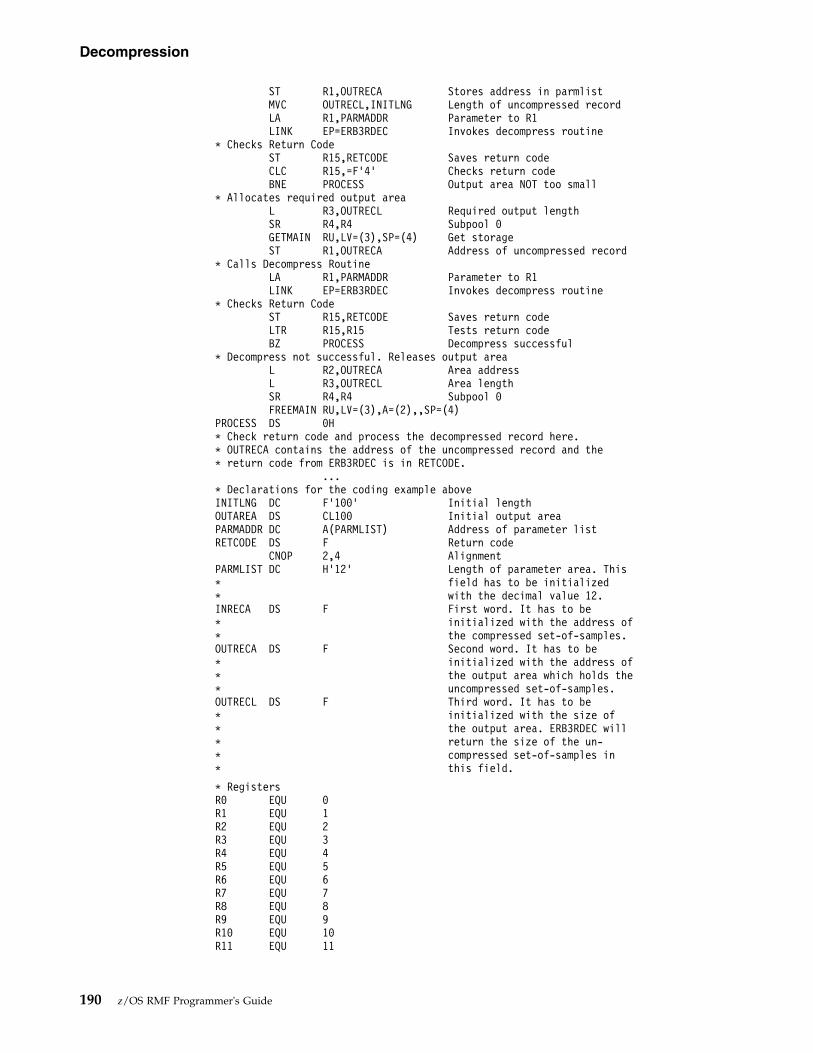
ST R1,OUTRECA Stores address in parmlistMVC OUTRECL,INITLNG Length of uncompressed recordLA R1,PARMADDR Parameter to R1LINK EP=ERB3RDEC Invokes decompress routine
* Checks Return CodeST R15,RETCODE Saves return codeCLC R15,=F’4’ Checks return codeBNE PROCESS Output area NOT too small
* Allocates required output areaL R3,OUTRECL Required output lengthSR R4,R4 Subpool 0GETMAIN RU,LV=(3),SP=(4) Get storageST R1,OUTRECA Address of uncompressed record
* Calls Decompress RoutineLA R1,PARMADDR Parameter to R1LINK EP=ERB3RDEC Invokes decompress routine
* Checks Return CodeST R15,RETCODE Saves return codeLTR R15,R15 Tests return codeBZ PROCESS Decompress successful
* Decompress not successful. Releases output areaL R2,OUTRECA Area addressL R3,OUTRECL Area lengthSR R4,R4 Subpool 0FREEMAIN RU,LV=(3),A=(2),,SP=(4)
PROCESS DS 0H* Check return code and process the decompressed record here.* OUTRECA contains the address of the uncompressed record and the* return code from ERB3RDEC is in RETCODE.
...* Declarations for the coding example aboveINITLNG DC F’100’ Initial lengthOUTAREA DS CL100 Initial output areaPARMADDR DC A(PARMLIST) Address of parameter listRETCODE DS F Return code
CNOP 2,4 AlignmentPARMLIST DC H’12’ Length of parameter area. This* field has to be initialized* with the decimal value 12.INRECA DS F First word. It has to be* initialized with the address of* the compressed set-of-samples.OUTRECA DS F Second word. It has to be* initialized with the address of* the output area which holds the* uncompressed set-of-samples.OUTRECL DS F Third word. It has to be* initialized with the size of* the output area. ERB3RDEC will* return the size of the un-* compressed set-of-samples in* this field.
* RegistersR0 EQU 0R1 EQU 1R2 EQU 2R3 EQU 3R4 EQU 4R5 EQU 5R6 EQU 6R7 EQU 7R8 EQU 8R9 EQU 9R10 EQU 10R11 EQU 11
Decompression
190 z/OS RMF Programmer's Guide

R12 EQU 12R13 EQU 13R14 EQU 14R15 EQU 15
Data set contentA MINTIME set of samples collected during the Monitor III gatherer session can beformatted and displayed during a Monitor III reporter display session. EachMINTIME set of samples is independent of other MINTIME sets of samples, and ifyou specify the same MINTIME value as that of the RANGE period for a displaysession, the report displays the information for that MINTIME set of samplescollected during the gatherer session. Measurement values for each MINTIME setof samples are organized as tables or records, the formats of which appear at theend of this chapter. The types of measurement tables or records are:
ERBASIG3ASID table
ERBCATG3Cache data information table
ERBCFIG3Coupling facility information table
ERBCPCDBCPC data control block
ERBCPDG3Channel data information table
ERBCPUG3Processor data control block
ERBCSRG3Common storage remaining table
ERBDSIG3Data set header and index
ERBDVTG3Device table
ERBENCG3Enclave data table
ERBENTG3Enqueue name table
ERBGEIG3General information table
ERBGGDG3Global gatherer data table
ERBOPDG3OMVS process data table
ERBRCDG3Resource collection data table
ERBREDG3Resource data record
Decompression
Chapter 7. Using Monitor III VSAM data set support 191

ERBSHDG3Sample header
ERBSSHG3MINTIME set of samples header
ERBSPGG3Storage group and volume data table
ERBSVPG3Service policy data table
ERBUWDG3USE/WAIT record
ERBXMHG3Moved samples header control block
Each is described in “Monitor III data set record and table formats” on page 194.Each offset is from the beginning of the table that contains the offset. Clock timesare local from the time-of-day (TOD) clock.
Figure 55 on page 193 shows the relationships between the Monitor III data setsupport tables and records.
VSAM data
192 z/OS RMF Programmer's Guide

The data set header and index (ERBDSIG3) describe the available measurementtimes (MINTIME sets of samples) and the data set offsets of each MINTIME set ofsamples header (ERBSSHG3).
The MINTIME set of samples header (ERBSSHG3) contains offsets to the addressspace id table (ERBASIG3), the device table (ERBDVTG3), enqueue name table(ERBENTG3), the general information table (ERBGEIG3), a group of sampleheaders (ERBSHDG3), and the common storage remaining table (ERBCSRG3).These tables describe information about each MINTIME interval within a data set.
Each sample header (ERBSHDG3) describes one sample CYCLE, and sampleheaders (ERBSHDG3) within one MINTIME are chained together by offsets.
The resource records (ERBREDG3) contain information about sampling for eachresource. RMF first samples each type of hardware and software resource; RMFthen samples user-written exit routines. The sample header (ERBSHDG3) foruser-written exit routines contains an offset to the first resource record.
Figure 55. Monitor III Measurement Table and Record Relationships
VSAM data
Chapter 7. Using Monitor III VSAM data set support 193

RMF creates in sequence one USE/WAIT record (ERBUWDG3) for each entry itfinds in the queue for each resource. The resource record (ERBREDG3) contains anoffset to the first USE/WAIT record for each resource.
The address space id table (ERBASIG3) contains one entry for each ASID/jobcombination. Each table entry contains the ASID number, its own index, and theindex of the previous table entry for the ASID. (During one MINTIME interval, ajob could exit, then reenter the system and therefore be assigned the same ASID. Inthis case, the job could have two sets of table entries for that MINTIME.)
The device table (ERBDVTG3) contains an entry for each device/VOLSERcombination. Each entry contains the device number, its own index, and the indexof the previous table entry for the device.
RMF correlates USE/WAIT records with their current table entries also by index.
To obtain the offset of each entry within the ASIG3 or DVTG3 table, multiply thelength of each table entry by the index (see Figure 55 on page 193).Index x length of table entry.
For higher level languages, ASIG3 or DVTG3 arrays can be accessed with the indexand an origin of 0.
To obtain the offset of each entry within the ENTG3 table, multiply the length ofeach table entry by the index (see Figure 55 on page 193) minus 1:(Index - 1) x length of table entry.
For higher level languages, the ENTG3 array can be accessed with the index andan origin of 1.
The common storage remaining table (ERBCSRG3) contains one entry for each jobthat ended and did not release all common storage. Each table entry contains theASID number, the jobname, the JES-ID, the termination date, the termination time,and the amount of remaining common storage.
Monitor III data set record and table formatsThis section describes the measurement records and tables used for the Monitor IIIdata set support function. Fields that are reserved for RMF are used for debuggingpurposes, for maintaining the data areas, or do not contain RMF Monitor III reportdata.
Note: The following record and table mappings apply only to the current releaseand are subject to change for future releases.
ERBASIG3 - Address space identification table
DecOffset
HexOffset
Name Length Format Description
ASIG3 Header Section:
0 0 ASIASIG3 5 EBCDIC Acronym ‘ASIG3’
5 5 ASIVERG3 1 binary Control block version X'1C'
6 6 ASIHDRLE 1 binary Length of ASIG3 header
7 7 * 1 * Reserved
VSAM data
194 z/OS RMF Programmer's Guide
|
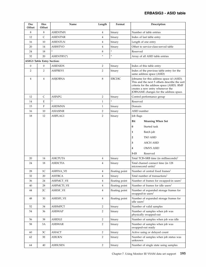
DecOffset
HexOffset
Name Length Format Description
8 8 ASIENTMX 4 binary Number of table entries
12 C ASIENTNR 4 binary Index of last table entry
16 10 ASIENTLN 4 binary Length of one entry
20 14 ASISSTVO 4 binary Offset to service-class-served table
24 18 * 8 * Reserved
32 20 ASIENTRY(*) * * Array of all ASID table entries
ASIG3 Table Entry Section:
0 0 ASIENIDX 2 binary Index of this table entry
2 2 ASIPREVI 2 binary Index of the previous table entry for thesame address space (ASID)
4 4 ASIJOBNA 8 EBCDIC Jobname for this address space id (ASID).This and the next 5 offsets describe the sortcriteria for the address space (ASID). RMFcreates a new entry whenever theJOBNAME changes for the address space.
12 C ASINPG 2 binary Control performance group
14 E * 1 * Reserved
15 F ASIDMNN 1 binary Domain
16 10 ASIASINR 2 binary ASID number
18 12 ASIFLAG1 2 binary Job flags
Bit Meaning When Set
0 Started task
1 Batch job
2 TSO ASID
3 ASCH ASID
4 OMVS ASID
5-15 Reserved
20 14 ASICPUTA 4 binary Total TCB+SRB time (in milliseconds)1
24 18 ASIDCTIA 4 binary Total channel connect time (in 128microsecond units)1
28 1C ASIFIXA_VE 4 floating point Number of central fixed frames1
32 20 ASITRCA 4 binary Total number of transactions1
36 24 ASIFMCT_VE 4 floating point Number of frames for swapped-in users1
40 28 ASIFMCTI_VE 4 floating point Number of frames for idle users1
44 2C ASIESF_VE 4 floating point Number of expanded storage frames forswapped-in users1
48 30 ASIESFI_VE 4 floating point Number of expanded storage frames foridle users1
52 34 ASISMPCT 2 binary Number of valid samples
54 36 ASISWAP 2 binary Number of samples when job wasphysically swapped-out
56 38 ASIIDLE 2 binary Number of samples when job was idle
58 3A ASISWAR 2 binary Number of samples when job wasswapped-out ready
60 3C ASIACT 2 binary Active using or delayed count
62 3E ASIUKN 2 binary Number of samples when job status wasunknown
64 40 ASISUSEN 2 binary Number of single state using samples
ERBASIG3 - ASID table
Chapter 7. Using Monitor III VSAM data set support 195

DecOffset
HexOffset
Name Length Format Description
66 42 ASISUCPR 2 binary Number of single state samples usingprocessor (PROC)
68 44 ASISUCDV 2 binary Number of single state samples usingdevice (DEV)
70 46 ASISWAIN 2 binary Number of single state samples delayed byany resource
72 48 ASISDCPR 2 binary Number of single state samples delayed bythe processor (PROC)
74 4A ASISDCDV 2 binary Number of single state samples delayed bydevice (DEV)
76 4C ASISDCST 2 binary Number of single state samples delayed bypaging or swapping (STOR)
78 4E ASISDCJE 2 binary Number of single state samples delayed byJES
80 50 ASISDCHS 2 binary Number of single state samples delayed byHSM
82 52 ASISDCEN 2 binary Number of single state samples delayed byENQ
84 54 ASIVECTA 4 binary Total accumulated vector processor time
88 58 ASISDCSU 2 binary Number of single state samples delayed bySUBS
90 5A ASISDCOP 2 binary Number of single state samples delayed byOPER
92 5C ASISDCMS 2 binary Number of single state samples delayed byOPER MESSAGE
94 5E ASISDCMT 2 binary Number of single state samples delayed byOPER MOUNT
96 60 ASIPAGES 2 binary Page delay
98 62 ASISWAPS 2 binary Swap delay
100 64 ASIDIV_VE 4 floating point Number of DIV frames
104 68 ASIAUXSC_VE 4 floating point Number of auxiliary slots
108 6C ASIPINA 4 binary Page-in counts
112 70 ASIDIVCT 2 binary Number of DIV invocations
114 72 ASIACTHF 2 binary Number of address spaces active andholding storage counter
116 74 ASISWAPI 2 binary Number of address spaces swapped in (notlogically and not physically swapped
118 76 ASISDCXC 2 binary Number of single state samples delayed byXCF - part of subs
120 78 ASIJCLAS 8 EBCDIC Job class, Source: OUCBCLS
128 80 ASIPINES 4 binary Expanded storage page-in count
132 84 ASIFLAG2 4 binary Common storage flags
Bit Meaning When Set
0 CSA amounts incomplete
1 SQA amounts incomplete
2 APPC initiator
3 BATCH initiator
4-31 Reserved
136 88 ASICSASC 4 binary CSA sample count
ERBASIG3 - ASID table
196 z/OS RMF Programmer's Guide

DecOffset
HexOffset
Name Length Format Description
140 8C ASISQASC 4 binary SQA sample count
144 90 ASICSAA 4 floating point CSA allocation
148 94 ASISQAA 4 floating point SQA allocation
152 98 ASIECSAA 4 floating point ECSA allocation
156 9C ASIESQAA 4 floating point ESQA allocation
160 A0 ASIJLCYC 4 binary Time-offset when this job was last found inthe system, expressed in CYCLE timeunits.
164 A4 ASIJOBST 8 EBCDIC Job selection time in GMT
172 AC ASIJESID 8 EBCDIC JES ID
180 B4 ASITET 4 binary Transaction elapsed time, in 1024 microsecsunits
184 B8 ASISRBTA 4 binary Total accumulated SRB time
188 BC ASIIOCNT 4 binary IO count
192 C0 ASILSCT 2 binary Count of "long" logical swaps
194 C2 ASIESCT 2 binary Count of "long" swaps to expanded storage
196 C4 ASIPSCT 2 binary Count of "long" physical swaps
198 C6 ASILSCF 4 floating point Sum of all central frames for logicallyswapped user at all samples.
202 CA ASILSEF 4 floating point Sum of all expanded frames for logicallyswapped user at all samples.
206 CE ASILSSA 2 binary Total logically swapped samples
208 D0 ASIPSEF 4 floating point Sum of all expanded frames for swappeduser (except logical) at all samples.
212 D4 ASIPSSA 2 binary Total swapped samples (except logical)
214 D6 ASIORTI 2 binary STOR/OUTR delay samples for swapreason 2: Terminal input wait
216 D8 ASIORTO 2 binary STOR/OUTR delay samples for swapreason 1: Terminal output wait
218 DA ASIORLW 2 binary STOR/OUTR delay samples for swapreason 3: Long wait
220 DC ASIORXS 2 binary STOR/OUTR delay samples for swapreason 4: Aux. storage shortage
222 DE ASIORRS 2 binary STOR/OUTR delay samples for swapreason 5: Real storage shortage
224 E0 ASIORDW 2 binary STOR/OUTR delay samples for swapreason 6: Detected long wait
226 E2 ASIORRQ 2 binary STOR/OUTR delay samples for swapreason 7: Requested swap. No longer used- refer to ASIORMP.
228 E4 ASIORNQ 2 binary STOR/OUTR delay samples for swapreason 8: Enqueue exchange swap
230 E6 ASIOREX 2 binary STOR/OUTR delay samples for swapreason 9: Exchange swap
232 E8 ASIORUS 2 binary STOR/OUTR delay samples for swapreason 10: Uniliteral swap
234 EA ASIORTS 2 binary STOR/OUTR delay samples for swapreason 11: Transition swap
236 EC ASIORIC 2 binary STOR/OUTR delay samples for swapreason 12: Improve central storage usage
ERBASIG3 - ASID table
Chapter 7. Using Monitor III VSAM data set support 197
|
|
||

DecOffset
HexOffset
Name Length Format Description
238 EE ASIORIP 2 binary STOR/OUTR delay samples for swapreason 13: Improve system paging rate
240 F0 ASIORMR 2 binary STOR/OUTR delay samples for swapreason 14: Make room for an out too longuser
242 F2 ASIORAW 2 binary STOR/OUTR delay samples for swapreason 15: APPC wait
244 F4 ASIORIW 2 binary STOR/OUTR delay samples for swapreason 16: OMVS input
246 F6 ASIOROW 2 binary STOR/OUTR delay samples for swapreason 17: OMVS output
248 F8 ASIRCLX 2 binary Report-class-list index
250 FA ASIORSR 2 binary STOR/OUTR delay samples for swapreason 18: In-real swap
252 FC ASICPUC 2 binary CPU capping delay
254 FE ASIACOM 2 binary Common paging
256 100 ASIAPRV 2 binary Private paging
258 102 ASIAVIO 2 binary VIO paging
260 104 ASIASWA 2 binary Swapping
262 106 ASIUNKN 2 binary Unknown count for calculating executionvelocity
264 108 ASICCAP 2 binary Resource capping delay
266 10A ASICQUI 2 binary Quiesce delay
268 10C ASIAXM 2 binary Cross-memory delay
270 10E ASIAHSP 2 binary Hiperspace™ delay
272 110 ASICUSE 4 binary CPU using
276 114 ASITOTD 4 binary Total delays for calculating executionvelocity
280 118 ASISRVO 4 binary Offset from service-class-servedtable-header to corresponding row
284 11C ASITOTSV 4 floating point Total number of shared page views in thisaddress space
288 120 ASISVINR 4 floating point Total number of shared pages in centralstorage that are valid for this address space
292 124 ASISPVLC 4 floating point Total number of shared page validations inthis address space
296 128 ASIGSPPI 4 floating point Total number of shared page-ins fromauxiliary storage for this address space
300 12C ASIGASPD 2 binary Number of single state samples delayed forshared storage paging
302 12E * 2 * Reserved
304 130 ASIOREPL 4 binary Number of outstanding replies
308 134 ASITOTU 4 binary Number of multi-state using samples
312 138 ASIIOU 4 binary Number of multi-state I/O using samples
316 13C ASIASSTA 4 binary Additional SRB time
320 140 ASIPHTMA 4 binary Preemptable-class SRB time
ERBASIG3 - ASID table
198 z/OS RMF Programmer's Guide

DecOffset
HexOffset
Name Length Format Description
324 144 ASIMSTS 4 binary Miscellaneous states.
Bit Meaning When Set
0 Address space is OMVS related
1 Address space matched aclassification rule in the activepolicy which prevents managingthe region based on the responsetime goals of its servedtransactions
2 CPU protection was assignedeither to the address space or totransaction service classes beingserved by the space, and SRM ishonoring the protection
3 Storage protection was assignedeither to the address space or totransaction service classes beingserved by the space, and SRM ishonoring the protection
4 This address space providesservice to transactions classifiedto a different class than theaddress space itself
5 WLM is managing this addressspace to meet the goals of workin other service classes
6 Address space is a CICS TORthat matched a classification rulein the active policy which allowsmanaging the region based onthe region goals but also ensuresthat completed transactions arereported and used formanagement of the CICS AORs
7 I/O priority group HIGH wasassigned either to the addressspace or to transaction serviceclasses served by the addressspace
8-31 Reserved
328 148 ASISUCIF 2 binary Number of single state samples usingzAAP
330 14A ASISUCIC 2 binary Number of single state samples usingzAAP on CP
332 14C ASISDCIF 2 binary Number of single state samples delayed byzAAP
334 14E ASISDCCP 2 binary Number of single state samples delayed bystandard CP
336 150 ASICPTA 4 binary Accumulated CPU time
340 154 ASIIFATA 4 binary Accumulated zAAP time
344 158 ASIIFCTA 4 binary Accumulated zAAP on CP time
348 15C ASIMCUSE 4 binary Multi state processor using count
352 160 ASIMCDLY 4 binary Multi state processor delay count
ERBASIG3 - ASID table
Chapter 7. Using Monitor III VSAM data set support 199

DecOffset
HexOffset
Name Length Format Description
356 164 ASISUCCP 2 binary Number of single state samples usingstandard CP
358 166 ASISUCSP 2 binary Number of single state samples using zIIP
360 168 ASISUCSC 2 binary Number of single state samples using zIIPon CP
362 16A ASISDCSP 2 binary Number of single state samples delayed byzIIP
364 16C ASI_TIME_ON_ZIIP 4 binary Accumulated zIIP time
368 170 ASI_ZIIP_TIME_ON_CP 4 binary Accumulated zIIP on CP time
372 174 ASI_IFA_PHTM 4 binary zAAP-only equivalent of ASIPHTMA
376 178 ASI_ZIIP_PHTM 4 binary zIIP-only equivalent of ASIPHTMA
380 17C ASI_LargeMemoryObjects 4 floating point Number of fixed 1 MB memory objectsallocated 1
384 180 ASI_LargePagesBackedInReal 4 floating point Number of 1 MB pages fixed in centralstorage 1
388 184 ASI_LVNMOMB 4 floating point Number of high virtual private memoryobjects allocated 1
392 188 ASI_HVCommonNMOMB 4 floating point Number of high virtual common memoryobjects allocated 1
396 18B ASI_LVSHRNMOMB 4 floating point Number of high virtual shared memoryobjects allocated 1
400 190 ASI_LVABytes 8 floating point Amount of storage allocated from highvirtual private memory in memory objects1
408 198 ASI_HVCommonBytes 8 floating point Amount of storage allocated from highvirtual common memory in memoryobjects 1
416 1A0 ASI_LVSHRBytes 8 floating point Amount of storage allocated from highvirtual shared memory in memory objects 1
424 1A8 ASI_HVCommonHWMBytes 8 floating point High water mark for the amount of highvirtual common storage allocated 1
432 1B0 ASI_LVMemLim 8 floating point Address space memory limit in MB 1
440 1B8 * 376 * Reserved
816 330 ASIQScanReq 8 binary Number of QScan requests issued by thisaddress space
824 338 ASIQScanSpecReq 8 binary Number of specific QScan requests issuedby this address space
832 340 ASIQScanRes 8 binary Number of resources returned by QScanrequests
840 348 ASIQScanResSq 16 binary Sum of the squares of ASIQScanRes
856 358 ASIQScanTime 8 binary Sum of QScan request times inmicroseconds
864 360 ASIQScanTimeSq 16 binary Sum of the squares of ASIQScanTime
880 370 ASI_1MBFixedFrames 4 floating point Number of 1 MB page-fixed frames usedfor pageable/DREF memory objects 1
884 374 ASI_1MBPageableFrames 4 floating point Number of 1 MB pageable/DREF frames1
888 378 * 112 * Reserved
1000 3E8 ASIDP 2 binary Dispatching priority
1002 3EA * 2 * Reserved
1004 3EC ASITRT 4 binary Transaction resident time
ERBASIG3 - ASID table
200 z/OS RMF Programmer's Guide

DecOffset
HexOffset
Name Length Format Description
1008 3F0 ASITRCA_S 4 binary Total accumulated number of transactions(sum)
1012 3F4 ASIDCTIA_S 4 binary Total accumulated channel connect time(sum)
1016 3F8 ASIIOCNT_S 4 binary Total EXCP count (sum)
1020 3FC * 4 * Reserved
1024 400 ASICPUTA_LF 8 floating point Total accumulated CPU time inmilliseconds
1032 408 ASITCBTA_LF 8 floating point Total accumulated TCB time inmilliseconds
1040 410 ASIFRXH_LF 8 floating point Number of fixed frames high
1048 418 ASIFRXA_LF 8 floating point Number of fixed frames above
1056 420 ASIFRXB_LF 8 floating point Number of fixed frames below
1064 428 ASI_HvShrPageValidations 4 floating point Number of page validations for highvirtual shared
1068 42C ASI_LvShr1MNMomb 8 floating point Number of shared 1M memory objectsallocated
1076 434 ASI_LvShr4KB 8 floating point Number of shared bytes from high virtualmemory in units of 4K
1084 43C ASI_LvShr1MGBytes 8 floating point High water mark for the amount of highvirtual shared storage allocated
1092 444 ASI_FreemainedFrames 8 floating point Number of freemained frames
1100 44C * 4 * Reserved
1104 450 ASISTAFL 4 binary Status Flags
1108 454 * 4 * Reserved
1112 458 ASI_2GMemoryObjects 8 floating point Number of fixed 2 GB memory objectsallocated1
1120 460 ASI_2GPagesBackedInReal 8 floating point Number of 2 GB pages fixed in centralstorage 1
1128 468 ASIORMP 2 binary STOR/OUTR delay samples for swapreason 7: Memory pool shortage
1 Sum of all values obtained at each sample. To obtain average values, divide by the number of valid samples (ASISMPCT).
ERBCATG3 - Cache data information table
Offsets
Name Length Format DescriptionDec Hex
CATG3 Header Section:
0 0 CATG3_Acro 5 EBCDIC Acronym 'CATG3'
5 5 CATG3_Ver 1 binary Control block version X'01'
6 6 * 2 * Reserved
8 8 CATG3_Tot_Len 4 binary Total length including this header, the maximumnumber of CATG3 array entries and all SMF 74subtype 5 records
12 C * 4 * Reserved
16 10 CATG3_Hdr_Len 2 binary Length of CATG3 header
18 12 CATG3_Entry_Len 2 binary Length of one CATG3 array entry
20 14 CATG3_Entry_Num 4 binary Number of CATG3 array entries in use
24 18 CATG3_Max_Num 4 binary Maximum number of CATG3 array entries
ERBASIG3 - ASID table
Chapter 7. Using Monitor III VSAM data set support 201
||||||
||||||
||||||
|||||||
|||||||
|||||||

Offsets
Name Length Format DescriptionDec Hex
28 1C * 20 * Reserved
48 30 CATG3_LDTO 8 binary Offset GMT to local time (STCK format)
56 38 * 8 * Reserved
CAT Table (CATG3) Array Entry:
0 0 CATG3_SSID 2 binary Cache subsystem ID (SSID)
2 2 CATG3_MDL 1 binary Subsystem model
3 3 * 1 * Reserved
4 4 CATG3_B_TOD 8 binary Cache interval GMT start time (STCK format)1
12 C CATG3_E_TOD 8 binary Cache interval GMT end time (STCK format)1
20 14 CATG3_Msg_Flg 2 binary If bit 8 is set, no SMF 74.5 record data availablefor this SSID
22 16 CATG3_Stat_Code 2 binaryStatus code.
0 = SMF 74.5 record data available4 = IOS return code given8 = IDCSS01 return code given
98 = System or User Abend given
24 18 CATG3_RC_IOS 2 binary IOS return code
26 1A CATG3_RC_IDCSS 2 binary IDCSS01 return code
28 1C * 1 * Reserved
29 1D CATG3_CMPC 3 binaryBit 0-11: System completion codeBit 12-23: User completion code
32 20 CATG3_Rec_VF 4 binary Offset to SMF 74 subtype 5 record with CacheSubsystem Activity data
36 24 CATG3_Rec_Lng 4 binary Length of SMF 74 subtype 5 record1 Device reserve activity can cause a data gatherer interface to wait until a RESERVE has been released. This in turn can cause thecache interval to be longer than the set of samples interval (see SSHTIBEG and SSHTIEND). To convert this value to local time,add CATG3_LDTO (see Header Section).
ERBCFIG3 - Coupling facility information table
Offsets
Name Length Format DescriptionDec Hex
CFIG3 Header Section:
0 0 CFICFIG3 5 EBCDIC Acronym 'CFIG3'
5 5 CFIVERG3 1 binary Control block version X'07'
6 6 CFIHDRLE 2 binary Length of CFIG3 header
8 8 CFITOTLE 4 binary Length of total CFIG3
12 C CFIENTLE 2 binary Length of one CFI entry
14 E CFIENTNR 2 binary Number of CFI entries
16 10 CFISTROF 4 binary Offset to first structure entry CFISTRUS
20 14 CFISTRLE 2 binary Length of one structure entry
22 16 CFISTRNR 2 binary Number of structure entries
24 18 CFISTEOF 4 binary Offset to first structure extension entry CFISTRES.If extensions exist, there is one CFISTRES entryfor a CFISTRUS entry.
28 1C CFISTELE 2 binary Length of one structure entry
ERBCATG3 - Cache data
202 z/OS RMF Programmer's Guide

Offsets
Name Length Format DescriptionDec Hex
30 1E CFISTENR 2 binary Number of structure entries
32 20 CFICONOF 4 binary Offset to first structure connection entryCFICONNS
36 24 CFICONLE 2 binary Length of one CFICONNS entry
38 26 CFICONNR 2 binary Number of CFICONNS entries
40 28 CFIRANGE 4 binary Reporting range in seconds
44 2C CFIPONAM 8 EBCDIC Policy name
52 34 CFIPOACT 8 EBCDIC Policy activation time
60 3C CFIPREQS 4 binary Policy is not large enough to contain allstructures that exist in the CF
64 40 CFIPREQC 2 binary Policy is not large enough to contain allconnections
66 42 * 18 * Reserved
68 44 CFICHPOF 4 binary Offset to first channel path entry CFICHPAS
72 48 CFICHPLE 2 binary Length of channel path entry
74 4A CFICHPNR 2 binary Number of channel path entries
76 4C CFISCMOF 4 binary Offset to first storage class memory entryCFISSCMS
80 50 CFISCMLE 2 binary Length of storage class memory entry
82 52 CFISCMNR 2 binary Number of storage class memory entries
CFI Table (CFIG3) Entry Section:
0 0 CFIENNAM 8 EBCDIC Name of CF
8 8 CFIENSYS 8 EBCDIC Name of system (from SYSNAME parameter ofIEASYSxx member)
16 10 CFIENST1 4 binary Index of first CFISTRUS/CFISTRES entries of thisCF
20 14 CFIENST# 4 binary Number of CFISTRUS/CFISTRES
24 18 CFIENLVL 4 binary CFLEVEL of microcode
28 1C CFIENMOD 4 EBCDIC CF model
32 20 CFIENVER 3 EBCDIC CF version
35 23 CFIENPAM 1 binary Path used mask for CFIENPID
ERBCFIG3 - Coupling facility data
Chapter 7. Using Monitor III VSAM data set support 203

Offsets
Name Length Format DescriptionDec Hex
36 24 CFIENFLG 2 binary Status flags
Bit Meaning When Set
0 Coupling Facility was connected to thesystem at the end of the MINTIME
1 Coupling Facility became active duringthe MINTIME
2 Coupling Facility structure hardwaredata gathered by RMF master gathereron this member
3 Coupling Facility structure hardwaredata gathered with CFDETAIL option
4 Coupling Facility structure hardwaredata snapshot values taken from SMFrecords
5 The CF storage is volatile when this bit= 1
6 Policy change pending which willdelete this coupling facility from theCFRM active policy when all allocatedstructures are gone from this couplingfacility
7 The coupling facility to CFRM policyreconcile process is in progress
8 The coupling facility has failed
9 CF dynamic dispatching
10 Recovery manager active
11 Maintenance mode active
12 Coupling thin interrupts are enabled
13-15 Reserved
38 26 CFIENSCG 2 binary Number of subchannels defined in the I/O gen
40 28 CFIENSCU 2 binary Number of subchannels currently in use
42 2A CFIENSCL 2 binary Number of subchannels that can be used (limit)
44 2C CFIENPID(8) 1 binary CF links. Valid entries have corresponding bit inCFIENPAM set
52 34 CFIENPNR 4 binary Number of online processors
56 38 CFIENBSY 4 binary Busy time in milliseconds
60 3C CFIENWAI 4 binary Wait time in milliseconds
64 40 CFIENPBC 4 binary Number of times CF requests failed due to pathbusy
68 44 CFIENSCC 4 binary Subchannel contention count (all subchannelbusy)
72 48 CFIENTSD 4 binary Total amount of CF storage defined (units = 4Kbyte blocks)
76 4C CFIENTSF 4 binary Amount of free CF storage (units = 4K byteblocks)
80 50 CFIENTOR 4 binary Number of total requests
84 54 CFIENTID(8) 1 binary CF link type. Valid entries have corresponding bitin CFIENPAM set
ERBCFIG3 - Coupling facility data
204 z/OS RMF Programmer's Guide

Offsets
Name Length Format DescriptionDec Hex
92 5C CFIENSCN 4 binary Connected MVS system counts - Number ofsystems connected to specified CF
96 60 CFIENSTI 4 binary Structure count in policy - Number of records forstructures in specified CF
100 64 CFIENSTO 4 binary Structure count out policy - Number of structuresin this CF which cannot be added to the policy
104 68 CFIENTCS 4 binary Total control space in 4K blocks. Control space +non-control space = total space
108 6C CFIENFCS 4 binary Total free control space in 4K blocks
112 70 CFIENTDS 4 binary Total dump space in 4K blocks
116 74 CFIENFDS 4 binary Free dump space in 4K blocks
120 78 CFIENSCT 8 binary Summed contention time in microseconds forwaiting for subchannels to become free forsynchronous immediate operations
128 80 CFIENFOC 4 binary Count of the number of summed times - forunsuccessful operations
132 84 CFIENFOT 8 binary Summed service time in microseconds ofunsuccessful operations
140 8C CFIENPDE 2 binary Number of dedicated processors
142 8E CFIENPSH 2 binary Number of shared processors
144 90 CFIENPWG 2 binary Shared processor average weight
146 92 CFIENPCO 1 binary Path composite mask for CFIENPID
147 93 * 1 * Reserved
148 94 CFIENCP1 4 binary Index of first channel path entry CFICHPASbelonging to this CF
152 98 CFIENCP# 4 binary Number of CFICHPAS entries belonging to thisCF
156 9C CFIENSC1 4 binary Index of first SCM entry CFISSCM belonging tothis CF
160 A0 CFIENSC# 4 binary Number of CFISSCM entries belonging to this CF
164 A4 * 4 * Reserved
168 A8 CFIENTSC 8 binary Total CF storage class memory in 4K blocks
176 B0 CFIENFSC 8 binary Free CF storage class memory in 4K blocks
184 B8 CFIENISM 2 binary Storage class memory increment in 4K blocks
CFISTRUS Table Entry Section:
0 0 CFISTNAM 16 EBCDIC Name of connected structure in this CF
16 10 CFISTVER 8 binary Structure Version number
24 18 CFISTTYP 1 binaryStructure type:1 = unserialized list2 = serialized list3 = lock4 = cache5 = unknown
25 19 * 3 * Reserved
ERBCFIG3 - Coupling facility data
Chapter 7. Using Monitor III VSAM data set support 205

Offsets
Name Length Format DescriptionDec Hex
28 1C CFISTFLG 1 binary Status Flags
Bit Meaning When Set
0 Structure was connected to the systemat the end of the MINTIME
1 Structure became active during theMINTIME
2 Async duplexing primary instance ofstructure
3 Async duplexing secondary instance ofstructure
4 Structure is encrypted
5-7 Reserved
29 1D * 1 * Reserved
30 1E CFISTEIN 2 binary Index of according CFI table entry
32 20 CFISTTRC 4 binary Total number of user requests completed
36 24 CFISTARC 4 binary Count of number of times for async. requestsexecuted by CF
40 28 CFISTATM 8 binary Summed service time for asynchronous requestsin microseconds
48 30 CFISTSRC 4 binary Count of number of times for sync. requestsexecuted by CF
52 34 CFISTSTM 8 binary Summed service time for synchronous requests inmicroseconds
60 3C CFISTSTA 4 binary Number of requests changed from synchronousto asynchronous
64 40 CFISTQRC 4 binary Count of number of times for queued requests
68 44 CFISTDRC 4 binary Number of times a request was found delayed incase of dump serialization
72 48 CFISTCN 4 binary Lock structure only: Number of times any requestencountered lock contention
76 4C CFISTFCN 4 binary Lock structure only: Number of times any requestencountered false lock contention (storagecontention within the structure)
80 50 CFISTCOM 2 binary Maximum number of connections allowed whenstructure was allocated in CF
82 52 * 2 * Reserved
84 54 CFISTCOT 4 binary Total of connections to the specified structure
88 58 CFISTCOP 4 binary Number of connections to the specified structurewith problems
92 5C CFISTQTM 8 binary Summed service time for queued requests inmicroseconds
ERBCFIG3 - Coupling facility data
206 z/OS RMF Programmer's Guide
||
||

Offsets
Name Length Format DescriptionDec Hex
100 64 CFISTFLE 2 binary Status flags extended.
Bit Meaning When Set
0 Only one structure allocated with thisname
1 Rebuild (old): The original activestructure is now the old structure
2 Rebuild (new): This structure is thenew structure
3 Transitional state
4 Hold state
5 Structure cannot be deallocated since adump table is associated with it
6 Structure failure for this version of thestructure
7 Structure allocated with STRDISP =KEEP
8 Change pending in structure policy
9 Structure is defined in policy
10 Structure contains users
11-15 Reserved
102 66 CFISTRBP 1 binary REBUILDPERCENT as specified in active CFRMpolicy
103 67 * 3 * Reserved
106 6A CFISTPL 35 EBCDIC CF preference list
141 8D CFISTXL 67 EBCDIC Structure exclusion list
208 D0 CFISTETM 8 floating point Summed structure execution time inmicroseconds
CFISTRES Table Entry Section:
0 0 CFIENCN1 4 binary Index of first CFICONNS entry belonging to thisstructure
4 4 CFIENCN# 4 binary Number of CFICONNS entries belonging to thisstructure
8 8 CFISTSIZ 4 binary Allocated size of structure (units = 4K byteblocks)
12 C CFISTMAE 4 binary List structure only: Maximum number ofelements. The estimated maximum number of listelements that may reside in storage class memoryis not included.
16 10 CFISTCUE 4 binary List structure only: Current number of elementsin use. The number of list elements that currentlyreside in storage class memory is not included.
20 14 CFISTLEL 4 binary List structure only: Limit on number of listentries. The estimated maximum number of listentries that may reside in storage class memory isnot included.
Lock structure: Limit on number of dataelements.
ERBCFIG3 - Coupling facility data
Chapter 7. Using Monitor III VSAM data set support 207

Offsets
Name Length Format DescriptionDec Hex
24 18 CFISTLEM 4 binary List structure only: Current number of list entriesused during MINTIME. The number of listentries that currently reside in storage classmemory is not included.
Lock structure: Current number of data elementsin use.
28 1C CFISTLTL 4 binary Lock + serialized List structure only Limit onnumber of lock table entries
32 20 CFISTLTM 4 binary Lock + serialized List structure only Maximumnumber of lock table entries used duringMINTIME
36 24 CFISTDEN 4 binary Cache structure only: Total directory entry count
40 28 CFISTDEL 4 binary Cache structure only: Total data element count
44 2C CFISCDEC 4 binary Cache structure only: Current directory entrycount
48 30 CFISCDAC 4 binary Cache structure only: Current data element count
52 34 CFISCRHC 4 binary Cache Read hit Counter
56 38 CFISCWHC 4 binary Cache Write hit counter
60 3C CFISCDER 4 binary Cache Directory entry reclaim counter
64 40 CFISCXIS 4 binary Cache XI counter
68 44 CFISCCOC 4 binary Cache Castout Counter
72 48 CFISTXSS 4 binary Maximum structure size (units = 4K byte blocks)
76 4C CFISTMSS 4 binary Minimum structure size (units = 4K byte blocks)
80 50 CFISTDTS 4 binary Structure dump table size (4k blocks)
84 54 CFISTLHD 4 binary Number of list headers (list only)
88 58 CFISTLEC 1 binary List element characteristic. Size of list element inbytes is 256*(2**LELX)
89 59 CFISTMDS 1 binary Maximum data list entry size (maximum numberof elements per entry)
90 5A CFISTLTC 1 binary Lock table entry characteristic
91 5B CFISTLFL 1 binary List structure flags
92 5C CFISTDEC 1 binary Data area element characteristic (cache only)
93 5D CFISTDAS 1 binary Maximum data area size (cache only)
94 5E CFISTDSC 1 binary Maximum storage class (cache only)
95 5F * 1 * Reserved
96 60 CFISTDCC 2 binary Maximum castout class (cache only)
98 62 CFISTFCC 2 binary First castout class (cache only)
100 64 CFISTLCC 2 binary Last castout class (cache only)
102 66 CFISTCFL 1 binary Cache structure flags
103 67 * 1 binary Reserved
104 68 CFISTCEN 4 binary Cache structure only: Total structure changedentry count.
108 6C CFISTCEL 4 binary Cache structure only: Total structure changeddata element count.
CFICHPAS Table Entry Section:
0 0 CFICHPID 1 binary ID of channel path connected to the CF
1 1 * 3 * Reserved
4 4 CFICHEIN 2 binary Index of according CFI table entry
ERBCFIG3 - Coupling facility data
208 z/OS RMF Programmer's Guide

Offsets
Name Length Format DescriptionDec Hex
6 6 * 2 * Reserved
8 8 CFICHTYPE 1 binary Channel path type
9 9 * 3 * Reserved
12 C CFICHFLAGS 4 binary Channel path validity flags
Bit Meaning When Set0 HCA ID and port number valid1 Channel path operation mode valid2 Latency valid3 Degraded bit valid4-7 Corresponding entry in CFICHSAP
valid8 Physical channel path ID valid9-31 Reserved
16 10 CFICHAID 2 binary Host channel adapter ID (HCA)
18 12 CFICHAPN 1 binary Host channel adapter port number
19 13 CFICHOPM 1 binary Channel path operation mode
20 14 CFICHLAT 4 binary Channel path latency time
24 18 CFICHSTA 1 binary Channel path status flags
Bit Meaning When Set0 Channel path is operating in degraded
mode1-7 Reserved
25 19 * 1 * Reserved
26 1A CFICHPCP 2 binary Physical channel path ID
28 1C CFICHSAP(4) 1 binary System assist processor to which the channel pathis accessible
32 20 * 4 * Reserved
CFISSCMS Table Entry Section:
0 0 CFISCNAM 16 EBCDIC Name of connected structure in this CF
16 10 CFISCVER 8 binary Structure Version number
24 18 CFISCMAX 8 binary Maximum amount of storage class memory thestructure can use in 4K-blocks
32 20 CFISCALG 1 binary SCM algorithm type
33 21 * 3 binary Reserved
36 24 CFISCFAU 4 binary Fixed augmented space in 4K-blocks
40 28 * 4 binary Reserved
44 2C CFISCIUA 4 binary Amount of augmented space in use by thestructure in 4K-blocks
48 30 CFISCIUS 8 binary Amount of storage class memory in use by thestructure in 4K-blocks
56 38 * 4 binary Reserved
60 3C CFISCEMA 4 binary Estimated maximum amount of space that maybe assigned as augmented space for the structurein 4K-blocks
64 40 CFISCEML 8 binary Estimated maximum number of list entries thatmay reside in storage class memory
72 48 CFISCEME 8 binary Estimated maximum number of list elements thatmay reside in storage class memory
80 50 CFISCENL 8 binary Number of existing structure list entries thatreside in storage class memory
ERBCFIG3 - Coupling facility data
Chapter 7. Using Monitor III VSAM data set support 209

Offsets
Name Length Format DescriptionDec Hex
88 58 CFISCENE 8 binary Number of existing structure list elements thatreside in storage class memory
CFICONNS Table Entry Section:
0 0 CFICNSIN 2 binary Index of according CFISTRUS table entry
2 2 * 2 * Reserved
4 4 CFICNSYS 8 EBCDIC Name of connecting system
12 C CFICNNAM 16 EBCDIC Name of connection
28 1C CFICNJOB 8 EBCDIC Name of connecting job
36 24 CFICNASI 2 binary ASID of connecting job
38 26 CFICNSTA 2 binaryConnection status:0 = Not known1 = Active2 = Failed Persistent3 = Failing4 = Disconnecting
40 28 CFICNCFL 4 binary CF Level requested for connect
44 2C CFICNFLG 2 binary Connection flags
Bit Meaning When Set
0 Rebuild allowed
1 Duplexing rebuild allowed
2 Structure alter allowed
3 Auto allowed
4 Auto allowed and suspend specified forconnection. Valid only whenALLAuto=ON. Applicable only whenCONN_Status = 1 .
5-15 Reserved.
ERBCPCDB - CPC data control block
Offsets Name Length Format Description
Dec Hex
CPCDB Header Section:
0 0 CPC_EyeCt 5 EBCDIC Name of CPCDB
5 5 CPC_VerNum 1 binary Control block version X'09'
6 6 * 2 * Reserved
8 8 CPC_HdrLen 4 binary Length of CPCDB header
12 C CPC_TotLen 4 binary Total length of CPCDB
16 10 CPC_Flags 2 binary Status flags
Bit Meaning When Set
0 No data from Sysevent REQLPDAT
1 Partition PHYSICAL exists
2 Data invalid
3-15 Reserved
18 12 CPC_MaxLpars 2 binary Maximum number of LPARs
ERBCFIG3 - Coupling facility data
210 z/OS RMF Programmer's Guide
|

Offsets Name Length Format Description
Dec Hex
20 14 CPC_MaxProcs 2 binary Maximum number of processors
22 16 CPC_PhysProcs 2 binary Number of physical processors
24 18 CPC_Homeo 4 binary Offset to home LPAR Section
28 1C CPC_Homel 2 binary Length of home LPAR Section
30 1E CPC_LparMainL 2 binary Length of CPC LPAR Section
32 20 CPC_LparO 4 binary Offset to CPC LPAR Sections
36 24 CPC_LparL 2 binary Length of CPC LPAR Section with CPC LogicalProcessor Section(s)
38 26 CPC_LparN 2 binary Number of CPC LPAR Sections
40 28 CPC_DTime 8 EBCDIC Time delta between two DIAG calls
Home LPAR Section:
0 0 CPC_HomeFlags 2 binary Status flags
Bit Meaning When Set
0 Capacity values available
1-2 Reserved
3 VARYCPU option set
4 WLM LPAR management enabled
5 Multithreading measurementsavailable
6 ABSMSUCAPPING option set
7-15 Reserved
2 2 * 2 * Reserved
4 4 CPC_CecMSU 4 binary Effective processor capacity available to theCPC
8 8 CPC_LparMSU 4 binary see LPDatImgCapacity of IRALPDAT
12 C * 4 * Reserved
16 10 CPC_HomeLPName 8 EBCDIC Name of the home partition
24 18 CPC_PhysAdj 4 binary see LPDatPhyCpuAdjFactor of IRALPDAT
28 1C CPC_WeightCumD 4 binary see LPDatCumWeight of IRALPDAT. This is thedelta between begin and end of MINTIME.
32 20 CPC_WeightNumD 4 binary see LPDatWeightAccumCounter of IRALPDAT.This is the delta between begin and end ofMINTIME.
36 24 * 2 * Reserved
38 26 CPC_CapAdj 1 binary Capacity adjustment indication
39 27 CPC_CapRsn 1 binary Capacity change reason
40 28 CPC_ImgMsuLimit 4 binary Image capacity MSU limit
44 2C CPC_4hAverage 4 binary see LPDatAvgImgService of IRALPDAT
48 30 CPC_UncappedTimeD 8 binary Uncapped time delta. SeeLPDatCumUncappedElapsedTime ofIRALPDAT. This is the delta between begin andend of MINTIME.
56 38 CPC_CappedTimeD 8 binary Capped time delta. SeeLPDatCumCappedElapsedTime of IRALPDAT.This is the delta between begin and end ofMINTIME.
ERBCPCDB - CPC DCB
Chapter 7. Using Monitor III VSAM data set support 211

Offsets Name Length Format Description
Dec Hex
64 40 CPC_MsuInterval 4 binary Approximate time interval (in seconds) for eachentry in the MSU table. seeLPDatServiceTableEntryInterval of IRALPDAT.
68 44 CPC_MsuDataEntries 4 binary Number of WLM intervals within the last 4hours.
72 48 * 384 * Reserved
456 1C8 CPC_GrpCapName 8 EBCDIC Name of the capacity group to which thepartition belongs
464 1D0 CPC_GrpCapLimit 4 binary MSU limit for the capacity group to which thispartition belongs
468 1D4 * 4 * Reserved
472 1D8 CPC_GrpJoinedTOD 8 binary Time when this LPAR has joined the group(STCK format)
480 1E0 * 192 * Reserved
672 2A0 CPC_Prod_AAP 4 Binary Multithreading core productivity numerator forAAP
676 2A4 CPC_Prod_IIP 4 Binary Multithreading core productivity numerator forIIP
680 2A8 CPC_Prod_CP 4 Binary Multithreading core productivity numerator forCP
684 2AC CPC_MaxCapF_AAP 4 Binary Multithreading Maximum Capacity Factornumerator for AAP
688 2B0 CPC_MaxCapF_IIP 4 Binary Multithreading Maximum Capacity Factornumerator for IIP
692 2B4 CPC_MaxCapF_CP 4 Binary Multithreading Maximum Capacity Factornumerator for CP
696 2B8 CPC_CapF_AAP 4 Binary Multithreading Capacity Factor numerator forAAP
700 2BC CPC_CapF_IIP 4 Binary Multithreading Capacity Factor numerator forIIP
704 2C0 CPC_CapF_CP 4 Binary Multithreading Capacity Factor numerator forCP
708 2C4 CPC_ATD_AAP 4 Binary Average Thread Density for AAP
712 2C8 CPC_ATD_IIP 4 Binary Average Thread Density for IIP
716 2CC CPC_ATD_CP 4 Binary Average Thread Density for CP
720 2D0 CPC_MODE_AAP 2 Binary MT Mode AAP
722 2D2 CPC_MODE_IIP 2 Binary MT Mode IIP
724 2D4 CPC_MODE_CP 2 Binary MT Mode CP
726 2D6 * 14 Binary Reserved
740 2E4 CPC_CecName 8 EBCDIC Name of the CPC
748 2EC CPC_Time_To_Cap 2 binary Remaining time until capping (in seconds)
750 2EE CPC_Time_To_Cap_Group 2 binary Remaining time until capacity group is subjectto capping (in seconds)
CPC LPAR Section:
0 0 CPC_LparName 8 EBCDIC LPAR name
8 8 CPC_LparId 2 binary LPAR number
ERBCPCDB - CPC DCB
212 z/OS RMF Programmer's Guide
|
|

Offsets Name Length Format Description
Dec Hex
10 A CPC_LparFlags 1 binary LPAR status flags
Bit Meaning When Set
0 This is the home partition
1 LPAR data invalid
2 Number of processors defined for thispartition exceeds limit
3 CPC_UPID is valid
4 Partition belongs to a capacity group;CPC_GroupName andCPC_GroupMLU are valid
5 WLM weight management enabled
6 Initial weight instead of currentweight should be used to projectusage of the members in the capacitygroup.
7 Reserved
11 B CPC_UPID 1 EBCDIC User partition ID
12 C CPC_LparDefMSU 4 binary Defined MSU limit
16 10 CPC_OSname 8 EBCDIC OS instance name
24 18 CPC_ProcO 4 binary Offset to Logical Processor Sections
28 1C CPC_ProcL 2 binary Length of Logical Processor Section
30 1E CPC_ProcN 2 binary Number of Logical Processor Sections
32 20 CPC_LPCname 8 EBCDIC LPAR cluster name
40 28 CPC_GroupName 8 EBCDIC Name of the capacity group to which thepartition belongs
48 30 CPC_GroupMLU 4 binary Group maximum license units
52 34 CPC_OnlineCS 4 binary Central storage (in MB) currently online to thispartition
56 38 CPC_HWGroupName 8 EBCDIC Name of hardware group to which thispartition belongs
CPC Logical Processor Section:
0 0 CPC_ProcId 2 binary Logical CPU address
2 2 CPC_ProcTyp 1 binary Processor type:
1=CP2=ICF-pool3=AAP4=IFL5=ICF6=IIP
3 3 * 1 * Reserved
ERBCPCDB - CPC DCB
Chapter 7. Using Monitor III VSAM data set support 213

Offsets Name Length Format Description
Dec Hex
4 4 CPC_ProcState 2 binary Processor status indicators
Bit Meaning When Set
0 Processor not available in MINTIME
1 Processor online
2 Processor dedicated
3 Wait completion = yes
4 Wait completion = no
5 Initial capping = 'ON'
6 Polarization flag: this partition isvertically polarized; that is,HiperDispatch mode is active.CPC_ProcPolarWgt is valid.
7-8 Polarization indicator:00 Horizontally polarized or
polarization not indicated01 Vertically polarized with
low entitlement10 Vertically polarized with
medium entitlement11 Vertically polarized with
high entitlement
9-15 Reserved.
6 6 CPC_ProcChgInd 2 binary Processor status-change indicators
Bit Meaning When Set
0 Changed from online to offline orvice-versa
1 Changed from shared to dedicated orvice-versa
2 'Initial capping' status changed
3 Wait completion changed
4 Maximum weight changed
5 Absolute limit on partition usagechanged
6 Hardware group name or absolutelimit on hardware group usagechanged
7-15 Reserved
8 8 CPC_ProcDispTimeD 8 binary Dispatch time between begin and end ofMINTIME in microseconds
16 10 CPC_ProcEffDispTimeD 8 binary Effective dispatch time between begin and endof MINTIME in microseconds
24 18 CPC_ProcOnlineTimeD 8 binary Online time between begin and end ofMINTIME in microseconds
32 20 CPC_ProcMaxWeight 2 binary Maximum LPAR share
34 22 CPC_ProcCurWeight 2 binary Current LPAR share
36 24 CPC_ProcMinWeight 2 binary Minimum LPAR share
38 26 CPC_ProcIniWeight 2 binary Defined (initial) LPAR weight
ERBCPCDB - CPC DCB
214 z/OS RMF Programmer's Guide

Offsets Name Length Format Description
Dec Hex
40 28 CPC_ProcPolarWeight 4 binary Weight for the logical CPU when HiperDispatchmode is active. See bit 6 of CPC_ProcState.Multiplied by a factor of 4096 for moregranularity.
44 2C CPC_HWCapLimit 4 binary If not zero, absolute limit on partition usage ofall CPUs of the type indicated in CPC_ProcTypin terms of a number specified in hundredths ofa CPU. For example, a value of 250 indicatesthat the partition is limited to using 2.5 CPUs.
48 30 CPC_HWGrpCapLimit 4 binary If not zero, absolute limit on partition usage ofall CPUs of the type indicated in CPC_ProcTypthat are members of the same hardware group,in terms of a number specified in hundredths ofa CPU. For example, a value of 250 indicatesthat the hardware group is limited to using 2.5CPUs.
52 34 * 4 binary Reserved
ERBCPDG3 - Channel data table
Offsets Name Length Format Description
Dec Hex
CPDG3 Header Section:
0 0 CPDACR 5 EBCDIC Acronym 'CPDG3'
5 5 CPDVER 1 EBCDIC Control block version X'01'
6 6 CPDHDRL 2 binary Length of CPDG3 header
8 8 CPDTOTL 4 binary Total length of CPDG3
12 C CPDNDAT 2 binary Number of online channel path data sections
14 E CPDLDAT 2 binary Length of channel path data section
16 10 CPDODAT 4 binary Offset to first channel path data section
Global channel information:
20 14 CPDSMP 4 binary Number of samples weighted by SRM, onlyvalid if bit 6 of CPDFLG = OFF
24 18 CPDFLG 1 binary Flags:
Bit Meaning When Set
0 No data
1 Running in LPAR mode
2 CPMF available
3 Configuration change
4 DCM supported by hardware
5 Configuration contains DCMmanaged channels
6 HW allows multiple channelsubsystems
7 Reserved
25 19 CPDCMI 1 binary CPMF mode info:0 = CPMF not available1 = Compatibility mode2 = Extended mode
ERBCPCDB - CPC DCB
Chapter 7. Using Monitor III VSAM data set support 215

Offsets Name Length Format Description
Dec Hex
26 1A CPDCSS 1 binary Channel subsystem ID, only valid if bit 6 ofCPDFLG = ON
27 1B CPDLPN 1 binary Logical partition number
28 1C CPDCFRC 4 binary CPMF restart count
32 20 CPDCFSC 4 binary CPMF sample count
36 24 * 12 EBCDIC For alignment
Channel path performance data:
0 0 CPDCPID 1 EBCDIC Channel path identification
1 1 CPDCFLG 1 binary Channel flags
Bit Meaning When Set
0 Channel path is online
1 Channel path is shared betweenlogical partitions
2 CPMF indication: this entry is invalid
3 Channel path is DCM managed
4 Channel characteristics changed
5-7 Reserved
2 2 CPDDFLG 1 binary Channel data flags for channel measurementgroup 2 or 3 data
Bit Meaning When Set
0 Channel characteristics word 1 valid
1 Channel characteristics word 2 valid
2 Channel characteristics word 3 valid
3 Channel characteristics word 4 valid
4 Channel characteristics word 5 valid
5-7 Reserved
3 3 CPDCPD 1 binary Channel path description. For an explanation,you can issue the command: D M=CHP.
4 4 CPDCPA 5 EBCDIC Channel path acronym
9 9 CPDCMG 1 binary Channel measurement group
10 A CPDCPP 1 binary Channel path parameter
11 B CPDGEN 1 binary Channel type generation
12 C CPDBSY 4 binary Number of samples the channel path was busy,weighted by SRM
16 10 CPDPBY 4 binary LPAR channel-path-busy time in units of 128micro-seconds
20 14 CPDCPTX 4 binary Extended last time stamp
20 14 * 1 binary Overflow area
21 15 CPDCPTS 3 binary Last CPMB entry time stamp in units of 128micro-seconds (note that this time value wrapsabout every 35.79 minutes)
24 18 * 24 * Reserved
48 30 CPDCCMC 20 EBCDIC Characteristics part
68 44 CPDCCMD 28 EBCDIC Measurements part
Channel measurement group 1 data - Characteristics part:
ERBCPDG3 - Channel data table
216 z/OS RMF Programmer's Guide

Offsets Name Length Format Description
Dec Hex
0 0 CPDCC1 20 EBCDIC not used
Channel measurement group 1 data - Measurements part:
20 14 CPDTUT 4 floating point CPMF total channel path busy time in units of128 micro-seconds
24 18 CPDPUT 4 floating point CPMF LPAR channel path busy time in units of128 micro-seconds
28 1C * 20 * Reserved
Channel measurement group 2 data - Characteristics part:
0 0 CPDMBC 4 floating point CPMF maximum bus cycles per second (word1)
4 4 CPDMCU 4 floating point CPMF maximum channel work units persecond (word 2)
8 8 CPDMWU 4 floating point CPMF maximum write data units per second(word 3)
12 C CPDMRU 4 floating point CPMF maximum read data units per second(word 4)
16 10 CPDUS 4 floating point CPMF data unit size in bytes (word 5)
Channel measurement group 2 data - Measurements part:
20 14 CPDTBC 4 floating point CPMF total bus cycle count
24 18 CPDTUC 4 floating point CPMF total channel work unit count
28 1C CPDPUC 4 floating point CPMF LPAR channel work unit count
32 20 CPDTWU 4 floating point CPMF total write data units
36 24 CPDPWU 4 floating point CPMF LPAR write data units
40 28 CPDTRU 4 floating point CPMF total read data units
44 2C CPDPRU 4 floating point CPMF LPAR read data units
Channel measurement group 3 data - Characteristics part:
0 0 CPDPDU 4 floating point CPMF LPAR data unit size in bytes (word 1)
4 4 CPDTDU 4 floating point CPMF total data unit size in bytes (word 2)
8 8 CPDPUM 4 floating point CPMF LPAR message sent unit size (word 3)
12 C CPDTUM 4 floating point CPMF total message sent unit size (word 4)
16 10 * 4 * Reserved
Channel measurement group 3 data - Measurements part:
20 14 CPDPMS 4 floating point CPMF LPAR message sent units count
24 18 CPDTMS 4 floating point CPMF total message sent units count
28 1C CPDPUS 4 floating point CPMF LPAR count of unsuccessful attempts tosend messages
32 20 CPDPUB 4 floating point CPMF LPAR count of unsuccessful attempts toreceive messages due to unavailable buffers
36 24 CPDTUB 4 floating point CPMF total count of unsuccessful attempts toreceive messages due to unavailable buffers
40 28 CPDPDS 4 floating point CPMF LPAR data units sent count
44 2C CPDTDS 4 floating point CPMF total data units sent count
ERBCPDG3 - Channel data table
Chapter 7. Using Monitor III VSAM data set support 217

ERBCPUG3 - Processor data control block
Offsets Name Length Format Description
Dec Hex
0 0 CPUG3_AC 5 EBCDIC Name of CPUG3
5 5 CPUG3_VE 1 binary Version of CPUG3
6 6 * 2 * Reserved
8 8 CPUG3_HDRL 4 binary Length of CPUG3 header
12 C CPUG3_TOTL 4 binary Total length this area
16 10 CPUG3_NUMPRC 8 binary Number of processors (online during totalMINTIME) multiplied by MINTIME (inmicroseconds)
24 18 CPUG3_LOGITI 8 binary Logical CPU time in microseconds. This is thesum of MVS NON_WAIT time of all onlinelogical processors in the time range
32 20 CPUG3_PHYSTI 8 binary Physical CPU time in microseconds. This is thesum of all CPU times used by all logical cores.In the case of a native (non PR/SM) system,this time is equal to the logical CPU time
40 28 CPUG3_STATUS 4 binary Status information
Bit Meaning When Set
0 BASIC mode system
1 LPAR mode system
2 Running as VM guest
3 Gatherer had permanent error
4 Diagnose 204 failed
5 VARY activity seen during the range.The number of logical processorsused to accumulate the CPU timevalues varied.
6 Diagnose 204 extended formatavailable
7 No MSU data available
8 Does not contain CPCDB data area
9 HISMT failed
10-31 Reserved
44 2C CPUG3_PRCON 4 binary Number of online processors at end ofMINTIME
48 30 CPUG3_NUMPRCOL 4 binary Accumulated number of online processors. Toget average number, divide by number ofsamples
52 34 CPUG3_NUMVECOL 4 binary Accumulated number of online vectorprocessors. To get average number, divide bynumber of samples
56 38 CPUG3_CPCOFF 4 binary Offset to CPCDB area
60 3C CPUG3_IFCON 4 binary Number of zAAPs online at end of range
64 40 CPUG3_NUMIFCOL 4 binary Accumulated number of zAAPs online. To getaverage number, divide by number of samples.
68 44 CPUG3_NUMPRIFA 8 binary Accumulated online time of zAAPs inmicroseconds
ERBCPUG3 - Processor DCB
218 z/OS RMF Programmer's Guide

Offsets Name Length Format Description
Dec Hex
76 4C CPUG3_LOGITIFA 8 binary Logical CPU time: The sum of MVSNON_WAIT time of all online logical zAAPs inthe time range (in microseconds)
84 54 CPUG3_PHYSTIFA 8 binary Physical CPU time: The sum of all CPU timesused by all online logical zAAPs in the timerange (in microseconds)
92 5C CPUG3_SUCON 4 binary Number of zIIPs online at end of range
96 60 CPUG3_NUMSUCOL 4 binary Accumulated number of zIIPs online. To getaverage number, divide by number of samples.
100 64 CPUG3_NUMPRSUP 8 binary Accumulated online time of zIIPs inmicroseconds
108 6C CPUG3_LOGITSUP 8 binary Logical CPU time: The sum of MVSNON_WAIT time of all online logical zIIPs inthe time range (in microseconds)
116 74 CPUG3_PHYSTSUP 8 binary Physical CPU time: The sum of all CPU timesused by all online logical zIIPs in the timerange (in microseconds)
124 7C CPUG3_PARK_CP 8 binary Accumulated parked time on CPs inmicroseconds
132 84 CPUG3_PARK_IFA 8 binary Accumulated parked time on zAAPs (IFAs) inmicroseconds
140 8C CPUG3_PARK_SUP 8 binary Accumulated parked time on zIIPs (SUPs) inmicroseconds
148 94 CPUG3_CPUOFF 4 binary Offset to CPUDB data area
152 98 CPUG3_CPOnlCore# 4 Binary Accumulated number of online CP cores. To getaverage number divide by number of samples.
156 9C CPUG3_IFAOnlCore# 4 Binary Accumulated number of online zAAP cores. Toget average number divide by number ofsamples.
160 A0 CPUG3_SUPOnlCore# 4 Binary Accumulated number of online zIIP cores. Toget average number divide by number ofsamples.
164 A4 * 4 * Reserved
ERBCSRG3 - Common storage remaining table
Offsets
Name Length Format DescriptionDec Hex
CSRG3 Header Section:
0 0 CSRCSRG3 5 EBCDIC Acronym ‘CSRG3’
5 5 CSRVERG3 1 binary Control block version X'01'
6 6 * 1 * Reserved
8 8 CSRHDRLE 2 binary Length of CSRG3 header
10 A CSRENTLE 2 binary Length of one entry
12 C * 4 * Reserved
16 10 CSRENTNR 4 binary Index of last available entry
20 14 * 12 * Reserved
CSRG3 Table Entry Section:
0 0 CSRASINR 2 binary ASID number
2 2 * 2 * Reserved
ERBCPUG3 - Processor DCB
Chapter 7. Using Monitor III VSAM data set support 219

Offsets
Name Length Format DescriptionDec Hex
4 4 CSRJOBNA 8 EBCDIC Jobname
12 C CSRJESID 8 EBCDIC JES-ID, taken from JSAB
20 14 CSRTDATE 4 EBCDIC Ending Date, packed decimal OYYYYDDD, seedocumentation of the 'TIME' macro
24 18 CSRTTIME 4 EBCDIC Ending Date, packed decimal HHMMSSth, seedocumentation of the 'TIME' macro
28 1C CSRCSA 4 binary CSA amount
32 20 CSRSQA 4 binary SQA amount
36 24 CSRECSA 4 binary ECSA amount
40 28 CSRESQA 4 binary ESQA amount
44 2C CSRFLAG 2 binary Common Storage Flags
Bit Meaning
0 CSA amounts complete
1 SQA amounts complete
2-15 Reserved
46 2E * 2 * Reserved
ERBDSIG3 - Data set header and index
Offsets
Name Length Format DescriptionDec Hex
DSIG3 Header Section:
0 0 DSIDSIG3 5 EBCDIC Acronym ‘DSIG3’
5 5 DSIGRMFV 1 binary Control block version X'02'
6 6 DSIGID 4 EBCDIC System identifier
10 A * 2 * Reserved
12 C DSIGTODC 8 binary Time data set was opened
20 14 DSIGTODF 8 binary Time stamp for first set of samples
28 1C DSIGTODL 8 binary Time stamp for last set of samples
36 24 DSIGFSPT 4 binary Offset of first set of samples from ERBDSIG3
40 28 DSIGLSPT 4 binary Offset of last set of samples from ERBDSIG3
44 2C DSIGNEPT 4 binary Offset of next set of samples to be written
48 30 DSIGFIPT 4 binary Offset of the first index entry from ERBDSIG3
52 34 DSIGLIPT 4 binary Offset of the last index entry from ERBDSIG3
56 38 DSIGNIPT 4 binary Offset of next index to be written
60 3C DSIGILEN 4 binary Length of an index entry
64 40 DSIGINUS 4 signed Number of current index to set of samples
68 44 DSIGTDSF 8 EBCDIC Time stamp of first policy
76 4C DSIGTDSL 8 EBCDIC Time stamp of last policy
84 54 DSIGFPPT 4 signed Offset to start of first policy
88 58 DSIGLPPT 4 signed Offset to start of the last policy
92 5c DSIGFPIP 4 signed Offset to first policy index
96 60 DSIGLPIP 4 signed Offset to last policy index
100 64 DSIGNPIP 4 signed Offset to next policy index
104 68 DSIGCIPN 4 signed Current index number to policy
ERBCSRG3 - CSR table
220 z/OS RMF Programmer's Guide

Offsets
Name Length Format DescriptionDec Hex
108 6C DSIGFIPN 4 signed First index number to policy
112 70 DSIGSPLX 8 EBCDIC Sysplex-ID of this system
120 78 DSIGSPXD 32 EBCDIC Reserved for sysplex
152 98 * 104 * Reserved
Data Set Index Section
0 0 DSIGTOD1 8 EBCDIC Time stamp for start of set of samples or servicepolicy
8 8 DSIGTOD2 8 EBCDIC Time stamp for end of set of samples or servicepolicy
16 10 DSIGSBEG 4 binary Offset from the start of the data set to the start ofthe set of samples or start of the service policy
20 14 DSIGSLEN 4 binary Physical (possibly compressed) length of the setof samples or length of service policy ascontained in SVPDLE
24 18 DSIGFLG 1 binary Data set flags
Bit Meaning
0 Service policy index
1-7 Reserved
25 19 * 3 * Reserved
ERBDVTG3 - Device table
Offsets
Name Length Format DescriptionDec Hex
DVTG3 Header Section:
0 0 DVTDVTG3 5 EBCDIC Acronym ‘DVTG3’
5 5 DVTVERG3 1 binary Control block version X'12'
6 6 DVTHDRLE 1 binary Length of DVTG3 header
7 7 DVTENTLE 1 binary Length of each table entry
8 8 DVTENTMX 4 binary Number of table entries
12 C DVTENTNR 4 binary Index of last table entry
16 10 DVTENTRY 144 EBCDIC Entry in the device table
Device Table (DVTG3) Entry Section:
0 0 DVTVOLI 6 EBCDIC VOLSER for this device
6 6 DVTENIDX 2 binary Reserved
8 8 DVTDEVNR 2 binary Device number in hexadecimal format
10 A DVTPREVI 2 binary Reserved
12 C DVTSMPCT 4 binary Number of valid samples
16 10 DVTSMPNR 4 binary Sample sequence number
ERBDSIG3 - DS header
Chapter 7. Using Monitor III VSAM data set support 221
|
|
|

Offsets
Name Length Format DescriptionDec Hex
20 14 DVTFLAG1 1 binary Device type indicator
Bit Meaning When Set
0 Reserved
1 DASD device
2 TAPE device
3 Number of alias exposures for a PAVdevice has changed
4 Virtual DASD
5 Reserved
6 LCU number is valid
7 Multiple exposure device (PAV)
21 15 DVTFLAG2 1 binary Device storage indicators — these flags indicate ifthe time values in offsets 24 through 60 areavailable.
Bit Meaning When Set
0 CONN/DISC/PEND time values atbegin time available
1 CONN/DISC/PEND time values atend time available
2 DEV BUSY DELAY/CUB DELAY/DPBDELAY time values at end timeavailable
3 DEV BUSY DELAY/CUB DELAY/DPBDELAY time values at end timeavailable
4 Device has PLPA page data sets
5 Device has COMMON page data sets
6 Device has LOCAL page data sets
7 Reserved
22 16 DVTMEXNR 2 binary Number of base and alias volumes
24 18 DVTDISIF 4 binary Native device DISC time at the beginning of theMINTIME for this set of samples (in2048-microsecond units)
28 1C DVTPETIF 4 binary Native device PEND time at the beginning of theMINTIME for this set of samples (in2048-microsecond units)
32 20 DVTCOTIF 4 binary Native device CONN time at the beginning of theMINTIME for this set of samples (in2048-microsecond units)
36 24 DVTDVBIF 4 binary Device busy delay time at the beginning of theMINTIME for this set of samples (in2048-microsecond units)
40 28 DVTCUBIF 4 * No longer used
44 2C DVTDISIL 4 binary Native device DISC time at the end of theMINTIME for this set of samples (in2048-microsecond units)
48 30 DVTPETIL 4 binary Native device PEND time at the end of theMINTIME for this set of samples (in2048-microsecond units)
ERBDVTG3 - Device table
222 z/OS RMF Programmer's Guide

Offsets
Name Length Format DescriptionDec Hex
52 34 DVTCOTIL 4 binary Native device CONN time at the end of theMINTIME for this set of samples (in2048-microsecond units)
56 38 DVTDVBIL 4 binary Device busy delay time at the end of theMINTIME for this set of samples (in2048-microsecond units)
60 3C DVTCUBIL 4 * No longer used
64 40 DVTTYP 4 EBCDIC Device type mapped by the UCBTYP macro
68 44 DVTIDEN 8 EBCDIC Device identification (device model)
76 4C DVTCUID 8 EBCDIC Control unit model
84 54 DVTSPBIF 4 * No longer used
88 58 DVTSPBIL 4 * No longer used
92 5C DVTIOQLC 4 binary I/O queue length count
96 60 DVTSAMPA 4 binary Accumulated I/O instruction count
100 64 * 2 * Reserved
102 66 DVTLCUNR 2 binary LCU number
104 68 DVTSAMPP 4 binary I/O instruction count (previous value)
108 6C DVTCMRIF 4 binary Initial command response time first
112 70 DVTCMRIL 4 binary Initial command response time last
116 74 DVTCUQTP 4 binary Control unit queuing time previous sample
120 78 DVTCUQTN 4 binary Accumulated control unit queuing time fordevices not connected to FICON channel
124 7C DVTCUQTF 4 binary Accumulated control unit queuing time fordevices connected to FICON channel
128 80 DVTHPNUM 4 signed Accumulated number of HyperPAV aliases ineach cycle
132 84 DVTPSM 4 signed Number of successful PAV samples
136 88 DVTFLAG3 1 binary Flag byte
Bit Meaning When Set
0 Device is a HyperPAV base device
1 HyperWrite requested on this device
2-7 Reserved
137 89 DVTHPCON 1 binary Configured HyperPAV aliases for that LSS
138 8A * 3 * Reserved
141 8D DVTSSID 1 binary Subchannel set
142 8E DVTDEVN2 2 binary Device number same as DVTDEVNR
144 90 DVTENIDX4 4 binary Index of this DVTG3 entry
148 94 DVTPREVI4 4 binary Index of previous DVTG3 entry
ERBENCG3 - Enclave data table
Offsets
Name Length Format DescriptionDec Hex
ENCARRAY
0 0 ENCG3ACR 5 EBCDIC Acronym 'ENCG3'
5 5 ENCG3VER 1 binary Control block version X'07'
ERBDVTG3 - Device table
Chapter 7. Using Monitor III VSAM data set support 223
||
||
||||||
||||||

Offsets
Name Length Format DescriptionDec Hex
6 6 * 2 * Reserved
8 8 ENCG3TLN 4 binary ENCG3 table length
12 C ENCG3TET (6) 12 binary table entry triplets
12 C ENCG3TEO 4 binary table entry offset
16 10 ENCG3TEL 4 binary table entry length
20 14 ENCG3TEN 4 binary table entry number
84 54 ENCG3DEO 4 binary descriptor entry offset
88 58 ENCG3DEL 4 binary descriptor entry length
92 5C ENCG3DEN 4 binary descriptor entry number
ENCG3 Header Section:
0 0 ENCG3LEN 4 binary table entry length
4 4 ENCTOKEN 8 EBCDIC enclave token
12 C ENCCLX 2 binary service class index
12 C ENCPGN 2 binary performance group
14 E ENCSRPG 2 binary subsystem RCLX/RPGN
16 10 ENCNRPG 2 binary trx name RPGN
18 12 ENCURPG 2 binary user ID RPGN
20 14 ENCCRPG 2 binary trx class RPGN
22 16 ENCARPG 2 binary account no RPGN
24 18 ENCPER 1 binary SC|PG period
25 19 ENCDMN 1 binary domain
26 1A ENCG3KFI 1 binary key field status flags
Bit Meaning When Set
0 key SC/PG has changed
1 key period has changed
2 domain has changed
3-7 Reserved
27 1B * 9 * Reserved
36 24 ENCG3EDO 4 binary offset from ENCG3 element to EDEG3element
40 28 ENCG3SMP 4 binary sample count
44 2C ENCUSTOT 4 binary using count Total
48 30 ENCDETOT 4 binary delay count Total
52 34 ENCIDLES 4 binary IDLE sample counts
56 38 ENCUNKNS 4 binary UNKNOWN sample counts
60 3C ENCUSCPU 4 binary using count CPU
64 40 ENCDECPU 4 binary delay count CPU
68 44 ENCDECCA 4 binary delay count CPU capping
72 48 ENCDESTG 4 binary delay count STOR paging
76 4C ENCDECOM 4 binary delay count COM paging
80 50 ENCDEXMM 4 binary delay count X/M
84 54 ENCDESHP 4 binary delay count Shared pag
ERBENCG3 - Enclave table
224 z/OS RMF Programmer's Guide

Offsets
Name Length Format DescriptionDec Hex
88 58 ENCFLAGS 2 binary ENCG3 descriptive flags
Bit Meaning When Set
0 dependent enclave
1 original independent enclave
2 foreign independent enclave
3 foreign dependent enclave
4-15 Reserved
90 5A ENCOASID 2 binary Owner ASID
92 5C ENCTOTS 4 binary multistate samples
96 60 ENCUMCPU 4 binary using count CPU (multistate samples)
100 64 ENCUMIO 4 binary using count I/O
104 68 ENCDMCPU 4 binary delay count CPU (multistate samples)
108 6C ENCDMIO 4 binary delay count I/O
112 70 ENCDMQUE 4 binary delay count queue
116 74 ENCDMCCA 4 binary delay count capping
120 78 ENCDMSTO 4 binary delay count storage
124 7C ENCMIDLE 4 binary idle count
128 80 ENCMUNKN 4 binary unknown count
132 84 ENCTCPUT 4 floating point CPU time since creation of enclave
136 88 ENCCPUT 4 floating point CPU time
140 8C * 8 * Reserved
148 94 ENCOWSYS 8 EBCDIC Enclave owner system or blank if not aforeign enclave
156 9C ENCOWJOB 8 EBCDIC Enclave owner jobname or blank if not aforeign enclave
164 9C ENCXTOK 32 EBCDIC Enclave export token or zero if not amulti-system enclave
196 C4 ENCTIFAT 4 floating point zAAP time since creation of enclave
200 C8 ENCTIFCT 4 floating point zAAP on CP time since creation of enclave
204 CC ENCIFAT 4 floating point zAAP time
208 D0 ENCIFCT 4 floating point zAAP on CP time
228 E4 ENCUSIFA 4 binary using count zAAP
232 E8 ENCUSIFC 4 binary using count zAAP on CP
236 EC ENCDEIFA 4 binary delay count zAAP
240 F0 ENCUMIFA 4 binary using count zAAP (multistate samples)
244 F4 ENCUMIFC 4 binary using count zAAP on CP (multistatesamples)
248 F8 ENCDMIFA 4 binary delay count zAAP (multistate samples)
252 FC ENCUSCP 4 binary using count CP (single state samples)
256 100 ENCDECP 4 binary delay count CP (single state samples)
260 104 ENCTSUPT 4 floating point zIIP time since creation of enclave
264 108 ENCTSUCT 4 floating point zIIP on CP time since creation of enclave
268 10C ENCSUPT 4 floating point zIIP time
272 110 ENCSUCT 4 floating point zIIP on CP time
276 114 * 16 * Reserved
ERBENCG3 - Enclave table
Chapter 7. Using Monitor III VSAM data set support 225

Offsets
Name Length Format DescriptionDec Hex
292 124 ENCUSSUP 4 binary using count zIIP (single state sample)
296 128 ENCUSSUC 4 binary using count zIIP on CP (single state sample)
300 12C ENCDESUP 4 binary delay count zIIP (single state sample)
304 130 ENCUMSUP 4 binary using count zIIP (multi state sample)
308 134 ENCUMSUC 4 binary using count zIIP on CP (multi state sample)
312 138 ENCDMSUP 4 binary delay count zIIP (multi state sample)
RMF Enclave Descriptor Entry (EDEG3)
0 0 EDETRXN 8 EBCDIC transaction program name
8 8 EDEUSER 8 EBCDIC user ID
16 10 EDETRXC 8 EBCDIC transaction class
24 18 EDENET 8 EBCDIC network ID
32 20 EDELU 8 EBCDIC logical unit name
40 28 EDEPLAN 8 EBCDIC plan
48 30 EDEPCKG 8 EBCDIC package name (filled ifEDE_PackageNameLong has not been filled)
56 38 EDECNCTN 8 EBCDIC connection
64 40 EDECOLL 18 EBCDIC collection
82 52 EDECORR 12 EBCDIC correlation
94 5E ECDSUBT 4 EBCDIC subsystem type
98 62 ECDFCN 8 EBCDIC function name
106 6A ECDSUBN 8 EBCDIC subsystem name
114 72 EDESSPM 255 EBCDIC subsystem parameter
369 171 EDEACCT 143 EBCDIC accounting info
512 200 EDE_ PROCEDURENAME 18 EBCDIC procedure name (filled ifEDE_ProcedureNameLong has not beenfilled)
530 212 EDE_PERFORM 8 EBCDIC Perform=value
538 21A * 2 * Reserved
540 21C EDE_PRIORITY 4 binary Subsystem priority in binary format.Contains X'80000000' if the subsystem didnot provide a priority.
544 220 EDE_ PROCESSNAME 32 EBCDIC process name
576 240 EDE_ SchedulingEnvironment 16 EBCDIC scheduling environment
592 250 EDE_ SchedulingEnvironment_Len
1 EBCDIC length of EDE_SchedulingEnvironment
593 251 * 3 * Reserved
596 254 EDE_SubsystemCollectionName
8 EBCDIC subsystem collection
604 25C EDE_PackageNameLong 128 EBCDIC package name - long version
732 2DC EDE_ PackageNameLong_Len 2 binary length of EDE_PackageNameLong
734 2DE EDE_ProcedureNameLong 128 EBCDIC procedure name - long version
862 35E EDE_ProcedureNameLong_Len
2 binary length of EDE_ProcedureNameLong
864 360 EDE_ClientIPAddress 39 EBCDIC client IP address
903 387 EDE_ClientIPAddress_Len 1 binary length of EDE_ClientIPAddress
904 388 EDE_ClientUserID 128 EBCDIC client user ID
1032 408 EDE_ClientUserID_Len 2 binary length of EDE_ClientUserID
ERBENCG3 - Enclave table
226 z/OS RMF Programmer's Guide

Offsets
Name Length Format DescriptionDec Hex
1034 40A EDE_ClientTrxName 255 EBCDIC client transaction name
1289 509 * 1 * Reserved
1290 50A EDE_ClientTrxName_Len 2 binary length of EDE_ClientTrxName
1292 50C EDE_ClientWksName 255 EBCDIC client workstation or hostname
1547 60B * 1 * Reserved
1548 60C EDE_ClientWksName_Len 2 binary length of EDE_EDE_ClientWksName
1550 60E EDE_ClientAccounting 512 EBCDIC client accouting information
2062 80E EDE_ClientAccounting_Len 2 binary length of EDE_ClientAccounting
ERBENTG3 - Enqueue name table
Offsets
Name Length Format DescriptionDec Hex
ENTG3 Header Section:
0 0 ENTENTG3 5 EBCDIC Acronym 'ENTG3'
5 5 ENTVERG3 1 binary Control block version X'02'
6 6 ENTHDRLE 1 binary Length of ENTG3 header
7 7 ENTENTLE 1 binary Length of one entry
8 8 ENTENTMX 4 binary Number of table entries
12 C ENTENTNR 4 binary Index of last filled entry (Highest possible indexis ENTENTMX)
16 10 ENTENTRY (*) 48 EBCDIC Entries in the ENTG3 table
ERBENTG3 Entry Section
0 0 ENTENIDX 2 binary ENQ NAME table entry index
2 2 ENTMAJNA 8 EBCDIC Major name of this resource
10 A ENTMINNA 36 EBCDIC Minor name of this resource
46 2E ENTSCOPE 1 binary Scope of this resource
Bit Meaning When Set
0 SYSTEM (When not set: NOSYSTEM)
1 SYSTEMS (When not set: NOSYSTEMS)
2 Reserved
3 GLOBAL (When not set: LOCAL)
4-7 Reserved
47 2F ENTFLAGS 1 binary Additional flags
Bit Meaning When Set
0 This resource has suspended jobs.
This flag is valid only during datagathering. It is not meaningful withinreporter.
1-7 Reserved
ERBENCG3 - Enclave table
Chapter 7. Using Monitor III VSAM data set support 227

ERBGEIG3 - General information table
DecOffset
HexOffset Name Length Format Description
0 0 GEIGEIG3 5 EBCDIC Acronym ‘GEIG3’
5 5 GEIVERG3 1 binary Control block version
6 6 GEILEN 2 binary Length of this control block (GEIG3)
8 8 * 16 * Reserved
24 18 GEIVERSN 1 binary CPU version number
25 19 * 1 * Reserved
26 1A GEIFLAG 1 binary Processor flags
Bit Meaning When Set
0 Service processor architecturesupported
1 PR/SM machine
2 Reserved
3 BEG
4 END
5 No collector data
6 Data in GEIGG3 is unpredictablebecause ERB3GGSS terminated
7 No ENQ contention data available dueto GRS system problem
27 1B GEIFLG1 1 binary Additional flags
Bit Meaning When Set
0 No ENQ contention data availablebecause of RMF/GRS interface problem
1 z/Architecture mode
2 CMR data available
3 zAAPs available
4 zIIPs available
5 Enhanced DAT facility 1 available
6 Pageable large pages support enabled
7 At least one zIIP is currently installed
28 1C GEIMODEL 2 packed CPU model number (The value is not signed.)
30 1E GEIIPSID 2 EBCDIC Installation performance specification (IPS)member suffix
32 20 GEIOPTN 2 EBCDIC Option (OPT) member suffix
34 22 GEIICSN 2 EBCDIC Installation control specification (ICS) membersuffix
36 24 GEISID 4 EBCDIC SYSTEM name (SMF system id)
40 28 * 4 * Reserved
44 2C GEIAHUIC_VE 4 floating point Current system UIC1
48 30 GEIRPOOL_VE 4 floating point Number of online real storage frames1
52 34 GEIRCOMA_VE 4 floating point Number of real storage COMMON frames1
56 38 GEIRSQAA_VE 4 floating point Number of real storage SQA frames1
60 3C GEIRAFC_VE 4 floating point Number of available real storage frames1
ERBGEIG3 - General table
228 z/OS RMF Programmer's Guide
|

DecOffset
HexOffset Name Length Format Description
64 40 GEINUCA_VE 4 floating point Number of nucleus (NUC) frames (real nucleusplus extended storage nucleus frames)1
68 44 GEIRSHR_VE 4 floating point Number of real storage shared frames1
72 48 * 4 * Reserved
76 4C GEIEESPL_VE 4 floating point Number of online extended storage frames1
80 50 GEIGAGE_VE 4 floating point Extended storage migration age1
84 54 GEIECOME_VE 4 floating point Number of extended storage COMMON frames1
88 58 GEIEAEC_VE 4 floating point Number of available extended storage frames1
92 5C * 4 * Reserved
96 60 GEIESQAF_VE 4 floating point Number of expanded storage SQA frames1
100 64 GEIRLPAF_VE 4 floating point Number of central storage LPA frames1
104 68 GEIELPAF_VE 4 floating point Number of expanded storage LPA frames1
108 6C GEIRCSAF_VE 4 floating point Number of central storage CSA frames1
112 70 GEIECSAF_VE 4 floating point Number of expanded storage CSA frames1
116 74 GEIASMPC 4 binary Monitor I sample count accumulated perMINTIME used by Monitor III reporter
120 78 GEIASQAO_VE 4 floating point Number of SQA overflow frames - BEGIN ofMINTIME used by Monitor III reporter1
124 7C GEICSARE 4 binary Amount of unallocated common area left (CSA +SQA)
128 80 * 4 * Reserved
132 84 GEICPUON 2 binary Snapshot number of online processors at end ofthe MINTIME1
134 86 * 2 * Reserved
136 88 GEICSASZ 4 binary IPL Size of CSA below 16M
140 8C GEISQASZ 4 binary IPL Size of SQA below 16M
144 90 GEIECSAZ 4 binary IPL Size of CSA above 16M
148 94 GEIESQAZ 4 binary IPL Size of SQA above 16M
152 98 GEISTCSA 4 binary Start of CSA/ECSA tracking (first fullword ofTOD)
156 9C GEISTSQA 4 binary Start of SQA/ESQA tracking (first fullword ofTOD)
160 A0 GEIENCSA 4 binary End of CSA/ECSA tracking (first fullword ofTOD)
164 A4 GEIENSQA 4 binary End of SQA/ESQA tracking (first fullword ofTOD)
168 A8 GEINSCSA 4 binary Number of CSA samples
172 AC GEINSSQA 4 binary Number of SQA samples
176 B0 GEICSAMX 4 binary Max. allocated CSA below 16M
180 B4 GEISQAMX 4 binary Max. allocated SQA below 16M
184 B8 GEIECSAX 4 binary Max. allocated CSA above 16M
188 BC GEIESQAX 4 binary Max. allocated SQA above 16M
192 C0 GEICSASP 4 binary Current allocated CSA below 16M
196 C4 GEISQASP 4 binary Current allocated SQA below 16M
200 C8 GEIECSAP 4 binary Current allocated CSA above 16M
204 CC GEIESQAP 4 binary Current allocated SQA above 16M
208 D0 GEICSAAV 4 floating point Accumulated allocated CSA below 16M1
212 D4 GEISQAAV 4 floating point Accumulated allocated SQA below 16M1
ERBGEIG3 - General table
Chapter 7. Using Monitor III VSAM data set support 229
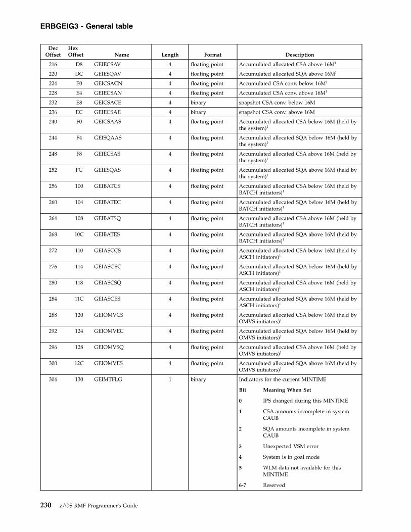
DecOffset
HexOffset Name Length Format Description
216 D8 GEIECSAV 4 floating point Accumulated allocated CSA above 16M1
220 DC GEIESQAV 4 floating point Accumulated allocated SQA above 16M1
224 E0 GEICSACN 4 floating point Accumulated CSA conv. below 16M1
228 E4 GEIECSAN 4 floating point Accumulated CSA conv. above 16M1
232 E8 GEICSACE 4 binary snapshot CSA conv. below 16M
236 EC GEIECSAE 4 binary snapshot CSA conv. above 16M
240 F0 GEICSAAS 4 floating point Accumulated allocated CSA below 16M (held bythe system)1
244 F4 GEISQAAS 4 floating point Accumulated allocated SQA below 16M (held bythe system)1
248 F8 GEIECSAS 4 floating point Accumulated allocated CSA above 16M (held bythe system)1
252 FC GEIESQAS 4 floating point Accumulated allocated SQA above 16M (held bythe system)1
256 100 GEIBATCS 4 floating point Accumulated allocated CSA below 16M (held byBATCH initiators)1
260 104 GEIBATEC 4 floating point Accumulated allocated SQA below 16M (held byBATCH initiators)1
264 108 GEIBATSQ 4 floating point Accumulated allocated CSA above 16M (held byBATCH initiators)1
268 10C GEIBATES 4 floating point Accumulated allocated SQA above 16M (held byBATCH initiators)1
272 110 GEIASCCS 4 floating point Accumulated allocated CSA below 16M (held byASCH initiators)1
276 114 GEIASCEC 4 floating point Accumulated allocated SQA below 16M (held byASCH initiators)1
280 118 GEIASCSQ 4 floating point Accumulated allocated CSA above 16M (held byASCH initiators)1
284 11C GEIASCES 4 floating point Accumulated allocated SQA above 16M (held byASCH initiators)1
288 120 GEIOMVCS 4 floating point Accumulated allocated CSA below 16M (held byOMVS initiators)1
292 124 GEIOMVEC 4 floating point Accumulated allocated SQA below 16M (held byOMVS initiators)1
296 128 GEIOMVSQ 4 floating point Accumulated allocated CSA above 16M (held byOMVS initiators)1
300 12C GEIOMVES 4 floating point Accumulated allocated SQA above 16M (held byOMVS initiators)1
304 130 GEIMTFLG 1 binary Indicators for the current MINTIME
Bit Meaning When Set
0 IPS changed during this MINTIME
1 CSA amounts incomplete in systemCAUB
2 SQA amounts incomplete in systemCAUB
3 Unexpected VSM error
4 System is in goal mode
5 WLM data not available for thisMINTIME
6-7 Reserved
ERBGEIG3 - General table
230 z/OS RMF Programmer's Guide

DecOffset
HexOffset Name Length Format Description
305 131 GEIFLG2 1 binary Additional flags
Bit Meaning When Set
0 Enhanced DAT facility 2 available
1-7 Reserved
306 132 * 2 * Reserved
308 134 GEISLID 4 EBCDIC ID of slip trap
312 138 GEIIPLTI 8 EBCDIC IPL time in TOD format (local time)
320 140 GEIWLMTK 8 EBCDIC WLM token
328 148 GEISPLXI 8 EBCDIC Sysplex name
336 150 GEISYSNM 8 EBCDIC MVS system name
344 158 GEIMAXAS 4 binary Maximum number of address spaces
348 15C GEIESPMB 4 floating point Storage frame movement count: page movementto expanded storage at begin of MINTIME
352 160 GEIESPME 4 floating point Storage frame movement count: page movementto expanded storage at end of MINTIME
356 164 GEIESMRB 4 floating point Storage frame movement count: migration fromexpanded storage to auxiliary storage at begin ofMINTIME
360 168 GEIESMRE 4 floating point Storage frame movement count: migration fromexpanded storage to auxiliary storage at end ofMINTIME
364 16C GEIMDL 16 EBCDIC CPC model identifier
380 17C GEISEQ 16 EBCDIC CPC sequence number
396 18C GEILOAL 4 floating point User region value allocated below 16M1
400 190 GEIHIAL 4 floating point LSQA/SWA/229/230 value allocated below 16M1
404 194 GEIELOAL 4 floating point User region value allocated above 16M1
408 198 GEIEHIAL 4 floating point LSQA/SWA/229/230 value allocated above 16M1
412 19C GEITOTPI 4 floating point Total number of paged-in pages, excludingswap-in, VIO, and hiperspace page-ins
416 1A0 GEISLTA 4 floating point Number of currently available slots 1
420 1A4 GEIRLMO 4 floating point Number of fixed memory objects allocated in thesystem that can be backed in 1 MB frames 1
424 1A8 GEIRLPR 4 floating point Number of 1 MB pages fixed in central storage 1
428 1AC GEICMO 4 floating point Number of high virtual common memory objectsallocated 1
432 1B0 GEICFR 4 floating point Number of high virtual common memory pagesbacked in central storage 1
436 1B4 GEICFFR 4 floating point Number of high virtual common memory pagesfixed in central storage 1
440 1B8 GEICASL 4 floating point Number of high virtual common memoryauxiliary storage slots (DASD and SCM) 1
444 1BC GEISMO 4 floating point Number of high virtual shared memory objectsallocated 1
448 1C0 GEISFR 4 floating point Number of high virtual shared memory pagesbacked in central storage 1
452 1C4 GEICSIZ 8 floating point High virtual common area size
460 1CC GEISSIZ 8 floating point High virtual shared area size1
468 1D4 GEILSIZ 4 floating point Maximum number of 1 MB frames that can beused by fixed 1 MB pages1
ERBGEIG3 - General table
Chapter 7. Using Monitor III VSAM data set support 231
||||||
||
||
||
||||||
||

DecOffset
HexOffset Name Length Format Description
472 1D8 GEIRTFIX 4 floating point Total number of fixed pages1
476 1DC GEIRBFIX 4 floating point Number of fixed frames below 16 MB centralstorage1
480 1E0 * 4 * Reserved
484 1E4 GEICUSE 8 floating point Number of high virtual common pages in-use
492 1EC GEISUSE 8 floating point Number of high virtual shared pages in-use
500 1F4 GEILPAG 4 floating point Reserved
504 1F8 GEILFUSE 4 floating point Number of 1 MB frames that are in-use and areno longer available for fixed 1 MB pages.
508 1FC GEILPUSE 4 floating point Number of 1 MB frames used by pageable/DREFmemory objects.
512 200 GEISASL 4 floating point Number of high virtual shared memory auxiliarystorage slots (DASD and SCM)1
516 204 GEIRSTRF 8 floating point Number of online real storage frames1
524 20C GEILCPR 8 floating point Number of 1 MB high virtual common memorypages backed in central storage 1
532 214 GEILCMO 4 floating point Number of fixed memory objects allocated incommon storage that can be backed in 1 MBframes1
536 218 GEILF4K 4 floating point Reserved
540 21C GEILP4K 4 floating point Reserved
544 220 GEILPFRI 4 floating point Number of failed 1 MB pageable pages that wererequested 1
548 224 GEILPFCI 4 floating point Number of demoted 1 MB pageable pages thatwere converted from 1 MB pages to 4K pages 1
552 228 GEILCMU 4 floating point Number of 1 MB high virtual common memoryobjects whose owner is no longer active1
556 22C GEILCPU 8 floating point Number of 1 MB high virtual common memorypages whose owner is no longer active1
564 234 GEILFPF 4 floating point Reserved
568 238 * 120 * Reserved
688 2B0 GEILSMO 8 floating point Number of memory objects allocated in highvirtual shared storage that can be backed in 1 MBframes1
696 2B8 GEIRFREM 8 floating point Number of freemained frames in all addressspaces1
704 2C0 GEIRGMO 8 floating point Number of fixed memory objects that areallocated in the system and are backed in 2 GBframes
712 2C8 GEIRGPR 8 floating point Number of 2 GB pages fixed in central storage
720 2D0 GEIGFUSE 8 floating point Number of 2 GB frames used by fixed memoryobjects
728 2D8 GEIGSIZ 8 floating point Number of 2 GB frames that can be used by fixed2 GB memory objects
736 2E0 GEILUSE 8 floating point Number of 1 MB frames in central storage thatare in-use by memory objects.
744 2E8 GEILTOT 8 floating point Total number of 1 MB frames in central storage.
Note: 1 Sum of values obtained at each sample. To obtain average values, divideby the number of valid samples (SSHSMPNR).
ERBGEIG3 - General table
232 z/OS RMF Programmer's Guide
|
||
||
|
|
|
||||||||
|||||||
|||||||
|||||||
||||||

ERBGGDG3 - Global gatherer data table
Offsets
Name Length Format DescriptionDec Hex
Control Flow Section
0 0 GGDGGDG3 5 EBCDIC Acronym 'GGDG3'
5 5 GGDRMFV 1 EBCDIC Control block version X'0B'
6 6 * 2 * Reserved
8 8 GGDCRETR 4 binary Pointer to RETG3 foot print area used for recovery
12 C GGDMODPT 4 binary Pointer to GGDMODAR area, array of all gatherer modules
16 10 GGDGOPPT 4 binary Pointer to GGDGOPT area, gatherer options
20 14 GGDCDCBP 4 binary Message DCB pointer
24 18 GGDTOFAG 4 binary Total number of failures of all gatherer modules
28 1C GGDALLPT 4 binary Pointer to ERBMFALL module
32 20 GGDCYECB 4 binary Cycle time ECB
Bit Meaning When Set
0 Cycle time ECB is waited on
1 Cycle time ECB is posted
2-31 Reserved
36 24 GGDSMPNR 4 binary Sample sequence number
40 28 GGDCBADS 4 binary Number of consecutive failing samples
44 2C GGDCBADT 4 binary Number of consecutive failing for debugging purposesamples threshold value
48 30 GGDCFLAG 4 binary Gatherer control flags
Bit Meaning When Set
0 Gatherer initializes
1 Gatherer terminates
2 MINTIME ended
3 SMF interval ended
4 Not fully initialized because the firstset-of-samples will be thrown away
5 New JES2 interface available
6-31 Reserved
52 34 GGDSTDIF 8 EBCDIC Local Greenwich time
60 3C GGDCTCYC 8 EBCDIC Cycle value in TOD format
68 44 GGDCTSTP 8 EBCDIC Stop time in TOD format
76 4C GGDCTMNT 8 EBCDIC MINTIME in TOD format
84 54 GGDCTCUC 8 EBCDIC Begin current cycle in TOD format
92 5C GGDCTNXC 8 EBCDIC Begin next cycle TOD format
100 64 GGDCTCUS 8 EBCDIC Begin current set-of-samples
108 6C GGDCTNXS 8 EBCDIC Begin next set-of-samples
Wrap-around Storage Management Section
116 74 GGDWSHPT 4 binary Pointer to wrap-around storage header
120 78 GGDWSHTL 4 binary Total length of wrap-around buffer
124 7C GGDWSHSP 4 binary Subpool number of wrap-around buffer
Set-of-samples Section
ERBGGDG3 - Global gatherer table
Chapter 7. Using Monitor III VSAM data set support 233
|

Offsets
Name Length Format DescriptionDec Hex
128 80 GGDSBEGG 8 EBCDIC Begin time gatherer
136 88 GGDSTBEC 8 EBCDIC Begin time current sample
144 90 GGDSTENC 8 EBCDIC End time current sample
152 98 GGDFSSHP 4 binary Pointer to first SSH control block
156 9C GGDLSSHP 4 binary Pointer to last SSH control block
160 A0 GGDCSSHP 4 binary Pointer to current SSH control block
164 A4 GGDSSHSP 4 binary Subpool of current set-of-sample area
ENQ Collection Data Space VIAADDR
168 A8 GGDDSALE 4 EBCDIC Alet of data space
172 AC GGDDSORG 4 binary Origin of data space
Cross-Memory Section
176 B0 GGDXCELL 4 binary Pointer to first cell element
180 B4 GGDXCNTR 4 binary Counter for CDS
184 B8 GGDXETDP 4 binary Pointer to entry table description
188 BC GGDJXCPT 4 binary Pointer to JXCG3 table
192 C0 GGDLXNUM 4 binary Number of LXs requested
196 C4 GGDLXVAL 4 binary LX value
200 C8 GGDTKNUM 4 binary Number of ETs created
204 CC GGDTKVAL 4 binary Token returned by ETCRE
HSM Section
208 D0 GGDMWELE 2 binary Length of copied MWE part
210 D2 GGDSTALE 2 binary Length of copied STA part
Data Set Support Section
212 D4 GGDDSTCB 4 binary Address of DS subtask TCB
216 D8 GGDDSNPT 4 binary Pointer to data set names table DSNG3
220 DC GGDDSSPT 4 binary Pointer to data set support table DSSG3
224 E0 GGDDSSCT 4 binary Counter of samples that should have been, but have notbeen, recorded on DS counted by ERB3GISS
228 E4 GGDDSECB 4 binary DS stop ECB - DS subtask signals stop complete
Bit Meaning When Set
0 DS stop ECB is waited on
1 DS stop ECB is posted
2-31 Reserved
232 E8 GGDSAVPT 4 binary Pointer to store subchannel save area
236 EC GGDIOSPT 4 binary Pointer to IOSB control block
240 F0 GGDSHBPT 4 binary Pointer to SCHIB control block
Miscellaneous Section
244 F4 GGDPMTPT 4 binary Pointer to performance measurement block
248 F8 GGDCPUVN 1 EBCDIC CPU version number
249 F9 * 3 * Reserved
252 FC GGDWSIPT 4 binary Pointer to wrap-around storage index header
256 100 GGDSID 4 EBCDIC SMF system-id field
260 104 GGDJESJN 8 EBCDIC JES jobname
268 10C GGDJESAS 2 binary JES ASID number
ERBGGDG3 - Global gatherer table
234 z/OS RMF Programmer's Guide

Offsets
Name Length Format DescriptionDec Hex
270 10E * 2 * Reserved
272 110 GGDSYNPT 4 binary Pointer to SYNG3 table
276 114 GGDMNTPT 4 binary Pointer to temporary OPER MOUNT area
280 118 GGDFLPCT 4 binary FLPA/EFLPA frames, calculated at initialization
284 11C * 4 * Reserved
288 120 GGDASCPT 4 binary Pointer to ASCG3 table
292 124 GGDCAPPT 4 binary Binary of common WLM services data capsule
296 128 GGDSPIPT 4 binary Binary of service policy chain
300 12C GGDCSVPP 4 binary Pointer to current SVPG3
304 130 GGDCSRQP 4 binary Pointer to RQAA capsule
308 134 GGDBDDPT 4 binary Pointer to diagnose x'204' data area
312 138 GGDCPUXP 4 binary Pointer to gatherer internal CPUX3 snapshot area
316 13C GGDCEDAA 4 binary Pointer to enclave data area
320 140 GGDCEDCC 4 binary Enclave data cycle count
324 144 GGDCEDFL 4 binary Enclave data flags
Bit Meaning When Set
0 Enclave data in cycle
1 Enclave data in MINTIME
2-31 Reserved
328 148 GGDDDNTP 4 binary Pointer to temporary data set name table
332 14C GGDBDDPG 4 binary Length of Diagnose X'204' data in 4K-byte pages
336 150 GGDCSFLG 1 binary Current set-of-samples control flags
Bit Meaning When Set
0 Write in progress
1 Message ERB321I issued
2-31 Reserved
337 151 GGDCSUCT 3 binary Current number of users reading the uncompressed data
340 154 GGDCSARL 4 binary Current set-of-samples area length
344 158 GGDCSARP 4 binary Current set-of-samples area address (in SUBSSHCF)
348 15C GGDVRICA 4 binary VSAMRLS data control area pointer
352 160 GGDOPDCA 4 binary OMVS process data control area pointer
356 164 * 140 * Reserved
GGDMODSE - Module Dependent Slot Entry Area
Offsets Name Length Format Description
Dec Hex
0 0 GGDMODEN (44) 48 EBCDIC Module dependent slot
GGDMODAR - Module Dependent Area
ERBGGDG3 - Global gatherer table
Chapter 7. Using Monitor III VSAM data set support 235
|

Offsets Name Length Format Description
Dec Hex
0 0 GGDAUFL1 1 binary Automatic storage control flag #1
Bit Meaning When Set
0 Storage assigned
1 Storage must not be freed
2-31 Reserved for user exit routine
1 1 GGDAUFL2 1 binary Automatic storage control flag #2
Bit Meaning When Set
0 Area for STA getmained
1-31 Reserved
2 2 GGDAUSBP 2 binary Subpool number
4 4 GGDAULEN 4 binary Length of automatic area
8 8 GGDAUPTR 4 binary Address of automatic area
12 C GGDMODNA 8 EBCDIC Module name
20 14 GGDMODAD 4 binary Entry address of module
24 18 GGDBADMC 1 binary Consecutive failures this module
25 19 GGDREDNR 1 binary RED number index
26 1A GGDREDID 1 binary RED id
27 1B GGDMODFL 1 binary Flag bits for this module
Bit Meaning When Set
0 This module selected to gatherer data
1 This module had permanent error
2 SDUMP requested, continue at retrybinary
3-31 Reserved
28 1C GGDTOFAM 4 binary Total number of failures of this module
32 20 * 16 * Reserved
RETG3 - Retry and Footprint Area
Offsets Name Length Format Description
Dec Hex
0 0 RETRETG3 5 EBCDIC Acronym 'RETG3'
5 5 RETRMFV 1 EBCDIC RETG3 control block version X'3'
6 6 RETSTACT 2 binary Current stack count
8 8 RETSAVE 72 binary Save area for ERB3GESA
80 50 * 12 * Reserved
ERBGGDG3 - Global gatherer table
236 z/OS RMF Programmer's Guide

Offsets Name Length Format Description
Dec Hex
92 5C RETFOOTP 1 binary Footprint area
Bit Meaning When Set
0 ERB3GINI entered
1 ERB3GTER entered
2 Reserved
3 ERB3GDAS entered
4 ERB3GSTO entered
5 ERB3GJS2 entered
6 ERB3GJS3 entered
7 ERB3GHSM entered
93 5D * 1 binaryBit Meaning When Set
0 ERB3GENQ entered
1 ERB3GMSU entered
2 ERB3GISS entered
3 ERB3GADR entered
4 ERB3GGET entered
5 ERB3GUSR entered
6 ERB3GDSI entered
7 ERB3GGSS entered
94 5E * 1 binaryBit Meaning When Set
0 ERB3GMES entered
1 ERB3GSMF entered
2 ERB3GSIS entered
3 ERB3GSMS entered
4 ERB3GXCF entered
5 ERB3GXCC entered
6 ERB3GMGP entered
7 ERB3GCSR entered
95 5F * 1 binaryBit Meaning When Set
0 ERB3GIXC entered
1 ERB3GIXI entered
2 ERB3GSTH entered
3 ERB3GCFS entered
4 ERB3GCFC entered
5 ERB3GCFI entered
6 ERB3GMRC entered
7 ERB3GMRG entered
ERBGGDG3 - Global gatherer table
Chapter 7. Using Monitor III VSAM data set support 237

Offsets Name Length Format Description
Dec Hex
96 60 * 1 binaryBit Meaning When Set
0 ERB3GSCM entered
1 ERB3GRQA entered
2 ERB3GSMG entered
3 ERB3GSIG entered
4 ERB3GEN0 entered
5 ERB3GEN1 entered
6 ERB3GEN2 entered
7 ERB3GEN3 entered
97 61 * 1 binaryBit Meaning When Set
0 ERB3GEN5 entered
1 ERB3GJSX entered
2 ERB3GSM2 entered
3 ERB3GHFS entered
4 ERB3GCTC entered
5 ERB3GVRI entered
6 ERB3GOPD entered
7 Reserved
98 62 * 2 * Reserved
100 64 RETFLAG2 1 binary Retry flag #2
Bit Meaning When Set
0 Recursion
1 XMEM established
2 ENQ environment established
3 Message data set opened
4 ERB3GXIT was entered
5 ERB425I issued for JES2
6 ERB425I issued for JES3
7 ERB425I issued for HSM
101 65 RETFLAG3 1 binary Retry flag #3
Bit Meaning When Set
0 ALESERV issued for data space, set onby ERB3GENQ, set off by ERB3GTER
1-3 Reserved
4 Store subchannel entered
5-7 Reserved
ERBGGDG3 - Global gatherer table
238 z/OS RMF Programmer's Guide

Offsets Name Length Format Description
Dec Hex
102 66 RETFLAG4 1 binary Retry flag #4
Bit Meaning When Set
0 User exit routine loaded
1 ERB3GDSI entered via error recoverymodule erb3gesa
2 ERB3GTEQ entered
3 ERB3GXTE entered
4 Cancel TTIMER request
5 ERBSMFI loaded
6-7 Reserved
103 67 * 29 * Reserved
132 84 RETSTAAR (10) 96 binary Retry stack area
RETSTACK - Retry Stack Element
Offsets Name Length Format Description
Dec Hex
0 0 RETTIMBE 8 EBCDIC Time stamp begin
8 8 RETADDR 4 binary Pointer to retry routine or zero
12 C RETCOUNT 4 binary Retry count for this CSECT
16 10 RETAMEMP 4 binary Pointer to module dependent slot
20 14 RETFLAG1 2 binary Retry flag #1
Bit Meaning When Set
0-1 Reserved
2 Issue message ERB280I
3 Issue message ERB268I
4 Issue message ERB269I
5-15 Reserved
22 16 RETRUBFL 2 binary Select registers flag
24 18 RETREGSA 64 binary Save area for RUB
88 58 RETLSIDX 4 binary Offset of link stack entry to recover
92 5C * 4 * Reserved
GGDGOPT - Options Area
Offsets Name Length Format Description
Dec Hex
0 0 GGDGOCYC 4 binary Gatherer option CYCLE
4 4 GGDGOSTP 4 binary Gatherer option STOP
Bit Meaning When Set
0 NOSTOP option active
1-31 Reserved
ERBGGDG3 - Global gatherer table
Chapter 7. Using Monitor III VSAM data set support 239

Offsets Name Length Format Description
Dec Hex
8 8 GGDGOSYN 4 binary Gatherer option SYNCH
Bit Meaning When Set
0 NOSYNCH option active
1-31 Reserved
12 C GGDGOMNT 4 binary Gatherer option MINTIME
16 10 * 3 * Reserved
19 13 GGDGOCLA 1 EBCDIC Gatherer option SYSOUT: sysout classalphanumeric value
20 14 GGDGORES 2 binary Resource selected options
Bit Meaning When Set
0 Resource Processor selected
1 Resource DASD selected
2 Resource Storage selected
3 Resource JES2 selected
4 Resource JES3 selected
5 Resource HSM selected
6 Resource ENQ selected
7 Resource Oper MSG selected
8 Resource Oper MOUNT selected
9 Resource XCF selected
10 Resource OMVS selected
11-14 Reserved
15 Resource User selected
22 16 GGDGOFL1 1 binary Flag byte #1
Bit Meaning When Set
0 Performance measurement active
1 Data set support selected
2 IPM measurement requested
3 CFDETAIL requested
4 CACHE requested
5 VSAMRLS requested
6 OPD requested
7 Reserved
23 17 * 1 * Reserved
24 18 GGDJESN 4 EBCDIC Name of JES subsystem chosen
28 1C GGDGOWHL 4 binary Value data set option WHOLD
32 20 GGDGOWST 4 binary Value of option WSTOR
36 24 GGDGOSOF 4 binary Offset of synch point from the full hourused by gatherer. Units are full seconds.
40 28 GGDGOCCU 4 binary Pointer to bit array for selected cache SSIDs
44 2C * 32 * Reserved
ERBGGDG3 - Global gatherer table
240 z/OS RMF Programmer's Guide

ERBOPDG3 - OMVS process data table
Offsets
Name Length Format DescriptionDec Hex
OPDG3 Header Section:
0 0 OPDOPDG3 5 EBCDIC Acronym 'OPDG3'
5 5 OPDVERG3 1 EBCDIC Control block version X'01'
6 6 OPDHDRLE 2 binary Length of OPDG3 header
8 8 OPDTOTLE 4 binary Total length of OPDG3
12 C OPDENTO 4 binary Offset to OPDG3 array
16 10 OPDENTL 4 binary Length of OPDG3 entry
20 14 OPDENTN 4 binary Number of OPDG3 entries
24 18 OPDSUMO 4 binary Offset to Summary data (OSDG3)
28 1C OPDSUML 4 binary Summary data length
32 20 OPDSTAT 4 binary Flags:
Bit Meaning When Set
0 OMVS inactive
1-31 Reserved
36 24 * 92 * Reserved
OSDG3: Summary information
0 0 OSDPROC 8 EBCDIC OMVS procedure name
8 8 * 2 * Reserved
10 A OSDKASID 2 binary Kernel address space ID
12 C OSDPLIST 40 EBCDIC OMVS parmlib member list
OPDG3 Array Entry:
0 0 OPDJOBNM 8 EBCDIC Job name (as noted in ASCB)
8 8 OPDUSER 8 EBCDIC User name (from login)
16 10 OPDPID 4 binary Process ID
20 14 OPDPPID 4 binary Parent's process ID
24 18 OPDASID 2 binary Address space ID. Undefined state if 0.
26 1A * 5 * Reserved
31 1F OPDSTYY 4 EBCDIC 4-digit year
35 23 OPDSTDD 3 EBCDIC 3-digit day of year (1-366)
38 26 OPDSTHH 2 EBCDIC Process start time hour
40 28 OPDSTMM 2 EBCDIC Process start time minute
42 2A OPDSTSS 2 EBCDIC Process start time second
44 2C OPDCT 8 EBCDIC Process system and user compute time in STCK format
52 34 OPDSTAT1 1 binary MVS status flags:
Bit Meaning When Set
0 Space swapped out
1 Ptrace kernel wait
2-7 Reserved
ERBOPDG3 - OMVS process data table
Chapter 7. Using Monitor III VSAM data set support 241

Offsets
Name Length Format DescriptionDec Hex
53 35 OPDSTAT2 1 binary Process status flags:
Bit Meaning When Set
0 Process stopped
1 Reserved
2 multiple threads
3 pthread task in process
4-7 Reserved
54 36 OPDSTAT3 1 EBCDIC State of reported task:A Message queue receive waitB Message queue sent waitC Communication system kernel waitD Semaphore operation waitE Quiesce frozenF File system kernel waitG MVS pause waitH Multiple threads, pthread_create usedI Swapped outK Other kernel waitL Cancelled, parent waitsM Multiple threads, no pthread_create usedP Ptrace kernel waitQ Quiesce termination waitR RunningS SleepingW Waiting for childX Creating new processZ Zombie. Cancelled, Parent does not wait
55 37 * 1 * Reserved
56 38 OPDLWPID 4 binary Latch process ID the process is waiting for (0 = notwaiting)
60 3C OPDGFLGS 4 binary General flags:
Bit Meaning When Set
0 Server information is valid (in fieldsOPDSNAME, OPDAFILE, OPDMFILE,OPDSTYPE)
1-31 Reserved
64 40 OPDSNAME 32 EBCDIC Server name in mixed case
96 60 OPDAFILE 4 binary Number of active files
100 64 OPDMFILE 4 binary Maximum number of files
104 68 OPDSTYPE 4 binary Server type
108 6C OPDCMND 40 EBCDIC Truncated command buffer in mixed case
148 94 OPDDCT 8 EBCDIC Delta TCB time
156 9C OPDDCtIIP 8 Binary Delta TCB time for zIIP
164 A4 * 4 Binary Reserved
168 A8 OPDCtIIP 8 Binary Process system and user compute time on zIIP
ERBOPDG3 - OMVS process data table
242 z/OS RMF Programmer's Guide

ERBRCDG3 - Resource collection dataResource Collection Data Header
DecOffset
HexOffset
Name Length Format Description
0 0 RCDACRO 5 EBCDIC Acronym 'RCDG3'
5 5 RCDVERS 1 binary Control block version
6 6 RCDHLEN 2 binary Size of RCDHDR
8 8 RCDSIZ 4 binary Size of all resource collection data. This includesRCDHDR, RCDBMAP, RCDG3, RCDPD, RCDRD andRCDSD.
12 C RCDPNAM 8 EBCDIC Policy name
20 14 RCDPTM 8 binary Local time policy was activated (TOD format)
28 1C RCDNTVL 4 binary Current sample interval (in milliseconds). This is thefrequency with which WLM samples delays reported inthe RCAA.
32 20 RCDNTV# 4 binary Total number of times WLM sampling code ran. Amonitor issuing successive calls to IWMRCOLL shouldnot assume that WLM sampling code ran at the intervalspecified by RCDNTVL between its calls. This field canbe used to translate sampled state data into actualpercentages of time.
36 24 RCDMSC# 2 binary Maximum possible number of service classes accordingto SVPOL service class array
38 26 RCDMRC# 2 binary Maximum possible number of report classes accordingto SVPOL report class array
40 28 RCDMPD# 2 binary Maximum possible number of service or report classperiod entries according to SVPOL.
42 2A RCDMRD# 2 binary Maximum possible number of response timedistribution buckets according to number of periodswith response time goals
44 2C RCDBMPL 2 binary Length of an entry in the response time distributionmapping array
46 2E RCDBMP# 2 binary Number of response time distribution buckets
48 30 RCDBMPO 4 binary Offset from begin of RCDHDR to response timedistribution mapping array (RCDBMAP)
52 34 RCDSCAL 2 binary Length of one RCDG3 workload activity entry in theRCDSCOF array
54 36 RCDSCA# 2 binary Number of entries in RCDSCOF array. This is thenumber of service classes returned in IWMSVPOL byIWMPQRY.
56 38 RCDSCOF 4 binary Offset from begin of RCDHDR to array of RCDG3entries. These entries represent service classes.
60 3C RCDRCAL 2 binary Length of one RCDG3 workload activity entry in theRCDRCOF array
62 3E RCDRCA# 2 binary Number of entries in RCDRCOF array. This field is thenumber of report classes returned in IWMSVPOL byIWMPQRY.
64 40 RCDRCOF 4 binary Offset from begin of RCDHDR to array of RCDG3entries
68 44 RCDPDAL 2 binary Length of one RCDG3 period entry in the RCDPD array
70 46 RCDPDA# 2 binary Number of entries in the RCDPD array
72 48 RCDPDAO 4 binary Offset from begin of RCDHDR to begin of RCDPD array
76 4C RCDRDAL 2 binary Length of one RCDG3 response time bucket entry in theRCDRD array
ERBRCDG3 - Resource collection data
Chapter 7. Using Monitor III VSAM data set support 243
|
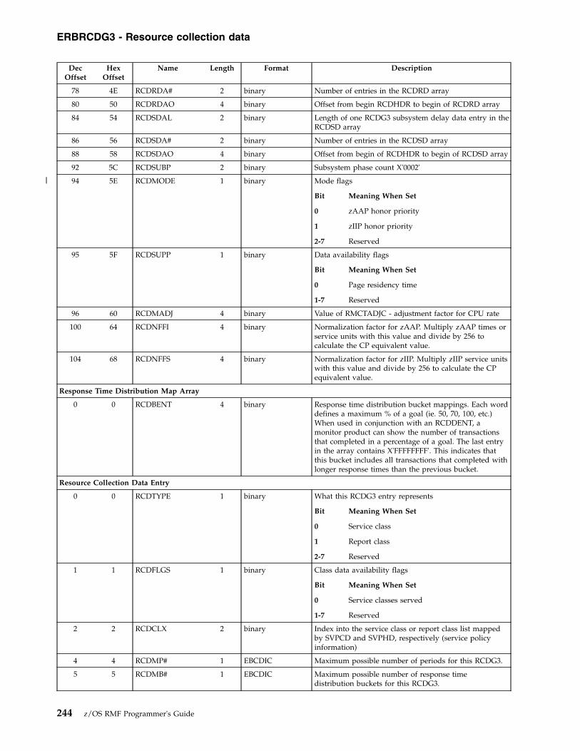
DecOffset
HexOffset
Name Length Format Description
78 4E RCDRDA# 2 binary Number of entries in the RCDRD array
80 50 RCDRDAO 4 binary Offset from begin RCDHDR to begin of RCDRD array
84 54 RCDSDAL 2 binary Length of one RCDG3 subsystem delay data entry in theRCDSD array
86 56 RCDSDA# 2 binary Number of entries in the RCDSD array
88 58 RCDSDAO 4 binary Offset from begin of RCDHDR to begin of RCDSD array
92 5C RCDSUBP 2 binary Subsystem phase count X'0002'
94 5E RCDMODE 1 binary Mode flags
Bit Meaning When Set
0 zAAP honor priority
1 zIIP honor priority
2-7 Reserved
95 5F RCDSUPP 1 binary Data availability flags
Bit Meaning When Set
0 Page residency time
1-7 Reserved
96 60 RCDMADJ 4 binary Value of RMCTADJC - adjustment factor for CPU rate
100 64 RCDNFFI 4 binary Normalization factor for zAAP. Multiply zAAP times orservice units with this value and divide by 256 tocalculate the CP equivalent value.
104 68 RCDNFFS 4 binary Normalization factor for zIIP. Multiply zIIP service unitswith this value and divide by 256 to calculate the CPequivalent value.
Response Time Distribution Map Array
0 0 RCDBENT 4 binary Response time distribution bucket mappings. Each worddefines a maximum % of a goal (ie. 50, 70, 100, etc.)When used in conjunction with an RCDDENT, amonitor product can show the number of transactionsthat completed in a percentage of a goal. The last entryin the array contains X'FFFFFFFF'. This indicates thatthis bucket includes all transactions that completed withlonger response times than the previous bucket.
Resource Collection Data Entry
0 0 RCDTYPE 1 binary What this RCDG3 entry represents
Bit Meaning When Set
0 Service class
1 Report class
2-7 Reserved
1 1 RCDFLGS 1 binary Class data availability flags
Bit Meaning When Set
0 Service classes served
1-7 Reserved
2 2 RCDCLX 2 binary Index into the service class or report class list mappedby SVPCD and SVPHD, respectively (service policyinformation)
4 4 RCDMP# 1 EBCDIC Maximum possible number of periods for this RCDG3.
5 5 RCDMB# 1 EBCDIC Maximum possible number of response timedistribution buckets for this RCDG3.
ERBRCDG3 - Resource collection data
244 z/OS RMF Programmer's Guide
|
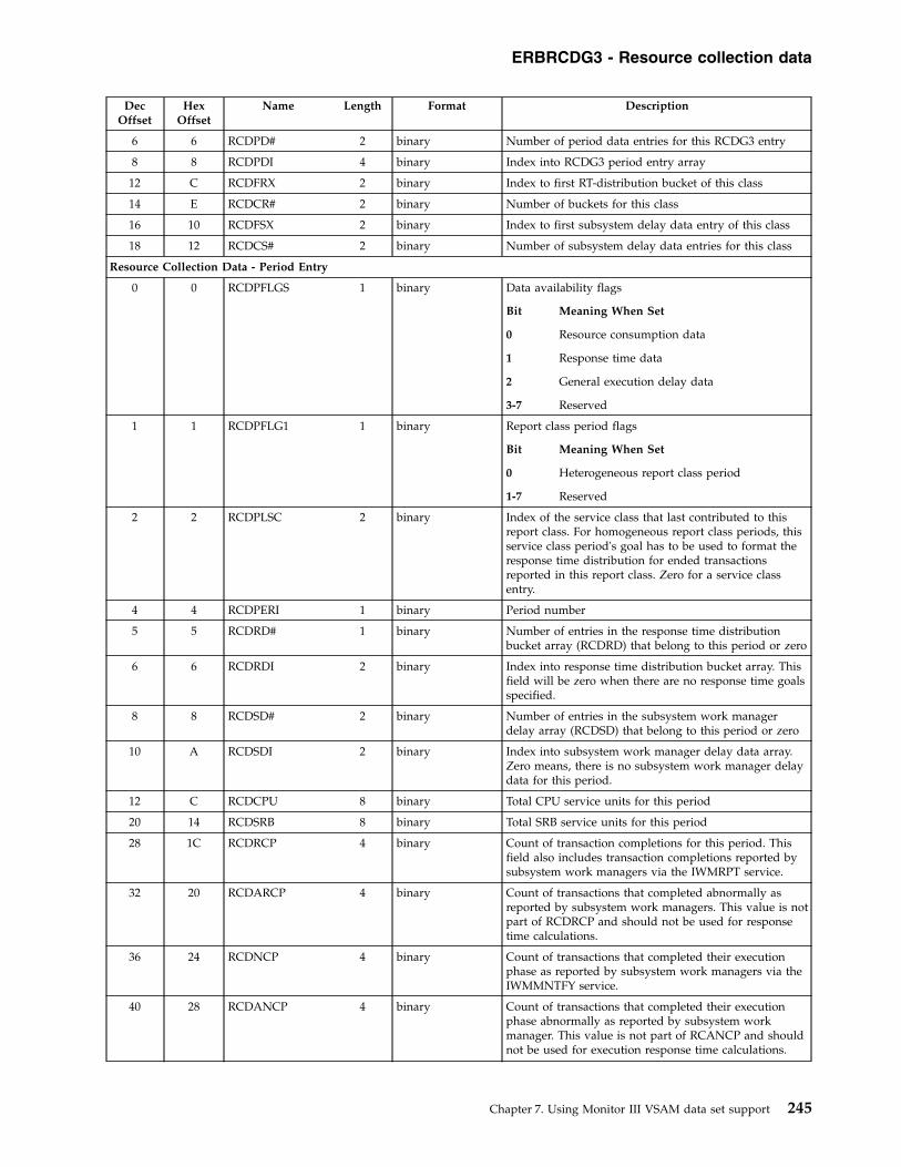
DecOffset
HexOffset
Name Length Format Description
6 6 RCDPD# 2 binary Number of period data entries for this RCDG3 entry
8 8 RCDPDI 4 binary Index into RCDG3 period entry array
12 C RCDFRX 2 binary Index to first RT-distribution bucket of this class
14 E RCDCR# 2 binary Number of buckets for this class
16 10 RCDFSX 2 binary Index to first subsystem delay data entry of this class
18 12 RCDCS# 2 binary Number of subsystem delay data entries for this class
Resource Collection Data - Period Entry
0 0 RCDPFLGS 1 binary Data availability flags
Bit Meaning When Set
0 Resource consumption data
1 Response time data
2 General execution delay data
3-7 Reserved
1 1 RCDPFLG1 1 binary Report class period flags
Bit Meaning When Set
0 Heterogeneous report class period
1-7 Reserved
2 2 RCDPLSC 2 binary Index of the service class that last contributed to thisreport class. For homogeneous report class periods, thisservice class period's goal has to be used to format theresponse time distribution for ended transactionsreported in this report class. Zero for a service classentry.
4 4 RCDPERI 1 binary Period number
5 5 RCDRD# 1 binary Number of entries in the response time distributionbucket array (RCDRD) that belong to this period or zero
6 6 RCDRDI 2 binary Index into response time distribution bucket array. Thisfield will be zero when there are no response time goalsspecified.
8 8 RCDSD# 2 binary Number of entries in the subsystem work managerdelay array (RCDSD) that belong to this period or zero
10 A RCDSDI 2 binary Index into subsystem work manager delay data array.Zero means, there is no subsystem work manager delaydata for this period.
12 C RCDCPU 8 binary Total CPU service units for this period
20 14 RCDSRB 8 binary Total SRB service units for this period
28 1C RCDRCP 4 binary Count of transaction completions for this period. Thisfield also includes transaction completions reported bysubsystem work managers via the IWMRPT service.
32 20 RCDARCP 4 binary Count of transactions that completed abnormally asreported by subsystem work managers. This value is notpart of RCDRCP and should not be used for responsetime calculations.
36 24 RCDNCP 4 binary Count of transactions that completed their executionphase as reported by subsystem work managers via theIWMMNTFY service.
40 28 RCDANCP 4 binary Count of transactions that completed their executionphase abnormally as reported by subsystem workmanager. This value is not part of RCANCP and shouldnot be used for execution response time calculations.
ERBRCDG3 - Resource collection data
Chapter 7. Using Monitor III VSAM data set support 245

DecOffset
HexOffset
Name Length Format Description
44 2C RCDTET 8 binary Total transaction elapsed time (in 1024-microsecondunits)
52 34 RCDXET 8 binary Total transaction execution time (in 1024-microsecondunits)
60 3C RCDCUSE 4 binary Total using samples
64 40 RCDTOTD 4 binary Total delay samples used in SRM's execution velocitycalculation
68 44 RCDQDT 8 binary Queue delay time (in 1024-microsecond units)
76 4C RCDADT 8 binary Resource affinity delay time (in 1024-microsecond units)
84 54 RCDCVT 8 binary JCL conversion delay time (in 1024-microsecond units)
92 5C RCDIQT 8 binary Ineligible queue time (in 1024-microsecond units)
100 64 RCDRCT 4 binary Total region control task time in microsecond units
104 68 RCDIIT 4 binary Total I/O interrupt time in microsecond units
108 6C RCDHST 4 binary Total hiperspace service time in microsecond units
112 70 RCDIFAT 8 binary Total zAAP service time in microsecond units. Multiplywith RCDNFFI and divide by 256 to calculate theequivalent time on a CP.
120 78 RCDIFCT 8 binary Total zAAP service time spent on CPs in microsecondunits
128 80 RCDIFASU 8 binary Total zAAP service units. Multiply with RCDNFFI anddivide by 256 to calculate the CP equivalent value
136 88 RCDIFASUCP 8 binary Total zAAP service units spent on CPs
144 90 RCDSUPSU 8 binary Total zIIP service units. Multiply with RCDNFFS anddivide by 256 to calculate the CP equivalent value
152 98 RCDSUPSUCP 8 binary Total zIIP service units spent on CPs
160 A0 RCDTPDP 8 binary Total CPU time spent for work units with promoteddispatching priority (in 1024-microsecond units).
168 A8 RCDCPUDL 4 binary CP delay samples
172 AC RCDAAPDL 4 binary zAAP delay samples
176 B0 RCDIIPDL 4 binary zIIP delay samples
180 B4 RCDRGCAP 4 binary Resource group capping delay samples
184 B8 * 52 * Reserved
236 EC RCDPRS 8 floating point Page residency time (in 1024 microsecond units)
244 F4 RCDXETX 8 binary Total transaction execution time (in microseconds)
252 FC RCDQDTX 8 binary Queue delay time (in microseconds)
260 104 RCDADTX 8 binary Resource affinity delay time (in microseconds)
268 10C RCDCVTX 8 binary JCL conversion delay time (in microseconds)
276 114 RCDIQTX 8 binary Ineligible queue time (in microseconds)
284 11C RCDRTDM 4 binary Midpoint of response time distribution. Equal to goal ifperiod with response time goal (unit as indicated inSVPG3). Zero if discretionary or system goal or no goaldefined.
Resource Collection Data - Response Time Distribution Array
0 0 RCDDENT 4 binary An entry in the RCDG3 response time distribution array.Each entry in the array contains the number oftransactions that completed in the time periodrepresented by that entry. When used with the responsetime distribution bucket mapping (RCDBMAP),monitors can construct a distribution of completionsversus goals specified.
Resource Collection Data - Subsystem Work Manager Delays
ERBRCDG3 - Resource collection data
246 z/OS RMF Programmer's Guide
|
||||
|
|
|
|
|
|

DecOffset
HexOffset
Name Length Format Description
0 0 RCDSTYP 4 EBCDIC Subsystem type, as used in the classification rulesspecified in the WLM administrative application
4 4 RCDEFLG 1 binary Flags
Bit Meaning When Set
0 Represents states sampled in the begin-to-endphase of a transaction
1 Represents states sampled in the executionphase of a transaction
2-7 Reserved
5 5 * 3 * Reserved
8 8 RCDESS# 4 binary Total number of transaction states sampled in the workphase specified by RCDEFLG
12 C RCDACTV 4 binary Total number of active state samples. Active indicatesthat there is a program executing on behalf of the workrequest, from the perspective of the work manager. Thisdoes not mean that the program is active from the basecontrol program's perspective.
16 10 RCDRDY 4 binary Total number of ready state samples. Ready indicatesthat there is a program ready to execute on behalf of thework request described by the monitoring environment,but the work manager has given priority to anotherwork request.
20 14 RCDIDL 4 binary Total number of idle state samples. Idle indicates that nowork request is available to the work manager that isallowed to run.
24 18 RCDWLOK 4 binary Total number of waiting for lock state samples
28 1C RCDWIO 4 binary Total number of waiting for I/O state samples. Waitingfor I/O indicates that the work manager is waiting foran activity related to an I/O request. This may be anactual I/O operation or some other function associatedwith the I/O request.
32 20 RCDWCON 4 binary Total number of waiting for conversation state samples.Waiting for conversation may have been used inconjunction with the WLM service IWMMSWCH toidentify where the recipient of the conversation islocated. In this case, only the switched state will berecorded.
36 24 RCDWDST 4 binary Total number of waiting for distributed request statesamples. Waiting for distributed request indicates a highlevel that some function or data must be routed prior toresumption of the work request. This is to be contrastedwith waiting for conversation, which is a low level viewof the precise resource that is needed. A distributedrequest could involve waiting on a conversation as partof its processing.
40 28 RCDWSL 4 binary Waiting for a session to be established locally, ie. on thecurrent MVS image
44 2C RCDWSN 4 binary Waiting for a session to be established somewhere in thenetwork
48 30 RCDWSS 4 binary Waiting for a session to be established somewhere in thesysplex
52 34 RCDWTMR 4 binary Waiting for a timer
56 38 RCDWO 4 binary Waiting for another product
ERBRCDG3 - Resource collection data
Chapter 7. Using Monitor III VSAM data set support 247

DecOffset
HexOffset
Name Length Format Description
60 3C RCDWMSC 4 binary Waiting for unidentified resource, possibly amonganother more specific category, but which may not bereadily determined
64 40 RCDSSL 4 binary State representing transactions for which there arelogical continuations on this MVS image. Subsystemwork managers might set this state when they functionship a transaction to another component within thesame MVS image.
68 44 RCDSSS 4 binary State representing transactions for which there arelogical continuations on another MVS image in thesysplex. Subsystem work managers might set this statewhen they function ship a transaction to anothercomponent on another MVS image within the sysplex.
72 48 RCDSSN 4 binary State representing transactions for which there arelogical continuations somewhere within the network.Subsystem work managers might set this state whenthey function ship a transaction to another componentwithin the network.
76 4C RCDBPMI 4 binary Number of state samples representing Db2 buffer poolmisses that resulted in I/O.
80 50 * 12 * Reserved
92 5C RCDWNL 4 binary Total number of state samples reflecting waiting for newlatch
96 60 RCDACTA 4 binary Total number of active application state samples. Activeapplication indicates a program is executing on behalf ofthe work request, from the perspective of the workmanager. This does not mean that the program is activefrom the base control program's perspective.
100 64 RCDWSSL 4 binary Total number of waiting for an SSL thread samples
104 68 RCDWRET 4 binary Total number of waiting for a regular thread samples
108 6C RCDWREW 4 binary Total number of waiting for a registration to a worktable samples
112 70 RCDWTY1 4 binary Total number of waiting for resource type 1 samples
116 74 RCDWTY2 4 binary Total number of waiting for resource type 2 samples
120 78 RCDWTY3 4 binary Total number of waiting for resource type 3 samples
124 7C RCDWTY4 4 binary Total number of waiting for resource type 4 samples
128 80 RCDWTY5 4 binary Total number of waiting for resource type 5 samples
132 84 * 40 * Reserved
ERBRCDG3 - Resource collection data
248 z/OS RMF Programmer's Guide

ERBREDG3 - Resource data record
Offsets
Name Length Format DescriptionDec Hex
0 0 REDENTRY(10) 12 EBCDIC RED Array
Entry Resource
1 USER
2 PROCESSOR
3 DEVICE
4 STORAGE
5 JES2/JES3
6 HSM
7 ENQ
8 MOUNT
9 MESSAGE
10 XCF
REDENTRY Section
0 0 REDREDID 1 binary Resource Data Record ID
1 1 REDFLAG1 1 binary Flags
Bit Meaning When Set
0 This resource is invalid
1 USE records available
2 WAIT records available
3-7 Reserved
2 2 * 2 * Reserved
4 4 REDFUWDO 4 binary Offset to first USE/WAIT record
8 8 REDUWDLE 2 binary For all resources except ENQ: Length ofUSE/WAI record
8 8 REDUWDL1 1 binary Short length of ENQ UWD record (withoutSystem/Jobname)
9 9 REDUWDL2 1 binary Total length of ENQ UWD record (withSystem/Jobname)
10 A REDUSERN 2 binary Number of user-exit records
ERBSHDG3 - Sample header
DecOffset
HexOffset Name Length Format Description
0 0 SHDSHDG3 5 EBCDIC Acronym 'SHDG3'
5 5 SHDRMFV 1 binary Control block version X'02'
6 6 SHDLEN 1 binary Length of SHDG3
7 7 SHDFLAG1 1 binary Sample flag
Bit Meaning When Set
0 Sample is invalid
1-7 Reserved
ERBREDG3 - Resource data
Chapter 7. Using Monitor III VSAM data set support 249

DecOffset
HexOffset Name Length Format Description
8 8 SHDPREVO 4 binary Offset to previous sample. This field contains theoffset within the Monitor III data gatherer areas.The Monitor III reporter module changes theoffset to a pointer after the data have been movedto the reporter's address space
12 C SHDNEXTO 4 binary Offset to next sample. This field contains theoffset within the Monitor III data gatherer areas.The Monitor III reporter module changes theoffset to a pointer after the data have been movedto the reporter's address space
16 10 SHDREDOF 4 binary Offset to first RED record
20 14 SHDREDNR 2 binary Number of RED records
22 16 SHDREDLE 2 binary Length of one REDG3 entry
24 18 * 6 * Reserved
30 1E SHDUWDNR 2 binary Number of Use/Wait records
32 20 * 16 * Reserved
ERBSPGG3 - Storage group and volume data
Offsets Name Length Format Description
Dec Hex
SPGG3 Header Section:
0 0 SPGACR 5 EBCDIC Acronym 'SPGG3'
5 5 SPGVER 1 binary Control block version X'01'
6 6 * 2 * Reserved
8 8 SPGHDRL 4 binary Length of SPGG3 header
12 C SPGTOTL 4 binary Total length of SPGG3
16 10 SPGSGDATL 4 binary Length of one storage group entry
20 14 SPGSGDATN 4 binary Number of storage group entries
24 18 SPGSGDATO 4 binary Offset to storage group entries
28 1C SPGVOLDATL 4 binary Length of one volume data entry
32 20 SPGVOLDATN 4 binary Number of volume data entries
36 24 SPGVOLDATO 4 binary Offset to volume data entries
40 28 SPGSTAT 2 binary Status flags
Bit Meaning When Set
0 No SPG data collected
1 Internal problem
2 SMS inactive
3-7 Reserved
8 No volume data available
9 no storage group data
10-15 Reserved
42 2A * 6 * Reserved
Storage Group Entry
0 0 GNAMEL 2 binary Actual length of storage group name
2 2 GNAME 30 EBCDIC Storage group name
ERBSHDG3 - Sample header
250 z/OS RMF Programmer's Guide

Offsets Name Length Format Description
Dec Hex
32 20 FIRSTVOL 2 binary Index of first volume entry for this storage group
34 22 NUMBERVOL 2 binary Number of volume entries for this storage group
36 24 * 4 * Reserved
Volume Data Entry
0 0 VNAMEL 2 binary Actual length of volume name
2 2 VNAME 6 EBCDIC Volume name (volser)
8 8 TOTALSPACE 4 binary Total space on volume (megabyte)
12 C FREESPACE 4 binary Free space on volume (megabyte)
16 10 LBLOCKSIZE 4 binary Largest block of unallocated space (megabyte)
20 14 * 4 * Reserved
ERBSSHG3 - MINTIME set of samples header
Offsets
Name Length Format DescriptionDec Hex
SSHG3 Header Section:
0 0 SSHSSHG3 5 EBCDIC Acronym ‘SSHG3’
5 5 SSHRMFV 1 binary Control block version X'0D'
6 6 SSHLEN 2 binary Length of SSHG3 header
8 8 SSHRMFVN 3 EBCDIC RMF version number
11 B SSHFLAG1 1 binary Flag byte
Bit Meaning
0 Data are compressed
1 WLM goal mode data
2-7 Reserved
12 C * 24 * Reserved
36 24 SSHSHDFO 4 binary Offset of first sample header from ERBSSHG3
40 28 SSHSHDLO 4 binary Offset of last sample header from ERBSSHG3
44 2C SSHTOTLE 4 binary Total length for this set of samples (including theset of samples header)
48 30 * 8 * Reserved
56 38 SSHSMPNR 4 binary Number of valid samples
60 3C SSHTIBEG 8 binary Begin time for this set of samples
68 44 SSHTIEND 8 binary End time for this set of samples
76 4C * 16 * Reserved
92 5C SSHASIO 4 binary Offset to ASID table from ERBSSHG3
96 60 * 12 * Reserved
108 6C SSHDVTO 4 binary Offset to DVT table from ERBSSHG3
112 70 * 8 * Reserved
120 78 SSHENTO 4 binary Offset to ENT table from ERBSSHG3
124 7C * 24 * Reserved
148 94 SSHGEIO 4 binary Offset to GEIG3 table from ERBSSHG3
ERBSPGG3 - Storage group and volume data
Chapter 7. Using Monitor III VSAM data set support 251

Offsets
Name Length Format DescriptionDec Hex
152 98 SSHIOML 1 binary Processor type on which data was created
Value Meaning
X'03' 9672, zSeries
153 99 SSHEFLAG 1 binary Extended storage indicators
Bit Meaning When Set
0 Extended storage installed
1-7 Reserved
154 9A SSHPRFGS 1 binary Processor flags
Bit Meaning When Set
0 ES/Connection Channel enabled
1 ES/Connection Director configured
2-7 Reserved
155 9B * 1 * Reserved
156 9C SSHGOCYC 4 binary Gatherer CYCLE option
160 A0 SSHGOSTP 4 binary Gatherer STOP option.
(If the first bit is set to 0, NOSTOP is in effect.)
164 A4 SSHGOSYN 4 binary Gatherer SYNC option.
(If the first bit is set to 0, NOSYNC is in effect.)
168 A8 SSHGOMNT 4 binary Gatherer MINTIME option
172 AC * 3 * Reserved
175 AF SSHGOCLA 1 EBCDIC Gatherer SYSOUT class option
176 B0 * 4 * Reserved
180 B4 SSHJESN 4 EBCDIC Name of JES subsystem
184 B8 SSHGOWHL 4 binary Gatherer DATASET WHOLD suboption
188 BC SSHGOWST 4 binary Gatherer WSTOR option
192 C0 * 40 * Reserved
232 E8 SSHSTDIF 8 binary Difference between local time and GreenwichMean Time where the difference equals local timeminus Greenwich Mean Time
240 F0 SSHHSMJN 8 EBCDIC Jobname of HSM subsystem
248 F8 SSHHSMAS 2 binary ASID number of HSM subsystem
250 FA SSHJESJN 8 EBCDIC Jobname of JES subsystem
258 102 SSHJESAS 2 binary ASID number of JES subsystem
260 104 * 8 * Reserved
268 10C SSHCSRO 4 binary Offset to CSR table from ERBSSHG3. This fieldcontains the offset when the data are within thewrap around buffer.
272 110 SSHJLCYC 4 binary Time-offset when the last cycle was gathered,expressed in CYCLE time units.
276 114 * 4 * Reserved
280 118 SSHRCDO 4 binary Offset to RCDG3 table from ERBSSHG3
284 11C SSHCPUO 4 binary Offset to CPUG3 table from ERBSSHG3
288 120 SSHIPLTI 8 binary IPL time in TOD format
296 128 SSHWLMTK 8 binary WLM token
304 130 SSHENCO 4 binary Offset to ENCG3 table from ERBSSHG3
ERBSSHG3 - Samples header
252 z/OS RMF Programmer's Guide

Offsets
Name Length Format DescriptionDec Hex
308 134 * 8 * Reserved
316 13C SSHCFIO 4 binary Offset to CFIG3 table from ERBSSHG3
320 140 SSHCATO 4 binary Offset to CATG3 table from ERBSSHG3
324 144 * 4 * Reserved
328 148 SSHOPDO 4 binary Offset to OPDG3 table from ERBSSHG3
332 14C * 4 * Reserved
336 150 SSHSPGO 4 binary Offset to SPGG3 table from ERBSSHG3
340 154 SSHCPDO 4 binary Offset to CPDG3 table from ERBSSHG3
344 158 * 24 * Reserved
ERBSVPG3 - Service policy
Offsets Name Length Format Description
Dec Hex
SVPG3 Header Section:
0 0 SVPNAM 5 EBCDIC Acronym 'SVPG3'
5 5 SVPDVN 1 binary Control block version
6 6 SVPDIL 2 binary Length of SVPG3 header
8 8 SVPDLE 4 binary Total length of the active service policy data structure
12 C SVPTIB 8 EBCDIC Begin time in TOD. Time of policy activation
20 14 SVPTIE 8 EBCDIC End time in TOD. Time of policy deactivation
28 1C SVPDPO 4 binary Offset to the service policy definition section
32 20 SVPDPL 2 binary Length of the policy entry in the policy section
34 22 * 2 * Reserved
36 24 SVPDWO 4 binary Offset to the workload definition section
40 28 SVPDWC 2 binary Number of workload entries in the workload definitionsection
42 2A SVPDWL 2 binary Length of each workload entry
44 2C SVPDCO 4 binary Offset to the service class definition section
48 30 SVPDCC 2 binary Number of service class entries in the service classdefinition section
50 32 SVPDCL 2 binary Length of each service class definition entry
52 34 SVPDZO 4 binary Offset of service class period entries
56 38 SVPDZC 2 binary Number of service class periods
58 3A SVPDZL 2 binary Length of each service class period entry
60 3C SVPDRO 4 binary Offset to the report class definition section
64 40 SVPDRC 2 binary Number of report class entries in the report classdefinition section
66 42 SVPDRL 2 binary Length of each report class definition entry
68 44 SVPDGO 4 binary Offset to the resource group definition section
72 48 SVPDGC 2 binary Number of resource group entries in the resource groupdefinition
74 4A SVPDGL 2 binary Length of each resource group definition entry
76 4C * 52 * Reserved
Service Policy
0 0 SVPNSP 8 EBCDIC Service policy name
ERBSSHG3 - Samples header
Chapter 7. Using Monitor III VSAM data set support 253
|

Offsets Name Length Format Description
Dec Hex
8 8 SVPDSP 32 EBCDIC Service policy description
40 28 SVPTPA 8 EBCDIC Time/date (TOD format) of policy activation
48 30 SVPIPU 8 EBCDIC User ID of the system operator or service administratorwho activated the service policy
56 38 SVPSNA 8 EBCDIC Name of the system on which policy activation wasinitiated
64 40 SVPSEQ 4 binary Classification sequence number
68 44 SVPASN 4 binary Activation sequence number
72 48 SVPIDN 8 EBCDIC Name of the service definition from which the servicepolicy was extracted
80 50 SVPTDI 8 EBCDIC Time/date (TOD format) that the service definition wasinstalled
88 58 SVPIDU 8 EBCDIC User ID of the service administrator who installed theservice definition
96 60 SVPIDS 8 EBCDIC Name of the system on which the service definition wasinstalled
104 68 SVPIDD 32 EBCDIC Description of service definition from which the servicepolicy was extracted
136 88 SVPCPU 4 binary CPU service coefficient *10000 - the number by whichaccumulated CPU service units will be multiplied(weighted)
140 8C SVPIOC 4 binary I/O service coefficient * 10000 - the number by whichaccumulated I/O service units will be multiplied(weighted)
144 90 SVPMSO 4 binary Storage service coefficient (MSO) * 10000 - the numberby which accumulated storage service units will bemultiplied (weighted)
148 94 SVPSRB 4 binary SRB service coefficient * 10000 - the number by whichaccumulated SRB service units will be multiplied(weighted)
152 98 SVPECP 4 EBCDIC EBCDIC representation of CPU service coefficient
156 9C SVPEIO 4 EBCDIC EBCDIC representation of I/O service coefficient
160 A0 SVPEMS 8 EBCDIC EBCDIC representation of Storage service coefficient
168 A8 SVPESR 4 EBCDIC EBCDIC representation of SRB service coefficient
172 AC * 4 * Reserved
Workload Information
0 0 SVPWNM 8 EBCDIC Workload name
8 8 SVPWDE 32 EBCDIC Workload description
Service Class Information
0 0 SVPCNM 8 EBCDIC Service class name
8 8 SVPCDE 32 EBCDIC Service class description
40 28 SVPCWN 8 EBCDIC Name of the workload this service class is associatedwith
48 30 SVPCRN 8 EBCDIC Name of the resource group this service class isassociated with - blanks if no resource group association
56 38 SVPCPO 4 binary Offset of service class period entries for this service class
60 3C SVPCPN 2 binary Number of service class periods for this service class
ERBSVPG3 - Service policy
254 z/OS RMF Programmer's Guide

Offsets Name Length Format Description
Dec Hex
62 3E SVPCFL 2 binary Class flags
Bit Meaning When Set
0 Reserved
1 Indicator for CPU critical
2 Indicator for Storage Protection
3-7 Reserved
8 Specialty engine eligible work in this serviceclass will not be offloaded to CPs for helpprocessing
9-15 Reserved
64 40 SVPCGI 4 binary Resource group index - the index of the resource groupentry in SVPRG of the resource group to which thisservice class belongs
68 44 SVPCWI 4 binary Workload index - the index of the workload entry inSVPWD of the workload to which this service classbelongs
72 48 SVPCRC 4 binary Number of periods with response time goals specified
Service Class Period Information
0 0 SVPTYP 4 binary Goal type indicators
Bit Meaning When Set
0 Percentile response time goal
1 Average response time goal
2 Velocity goal
3 Discretionary goal
4 System goal
5-7 Reserved
4 4 * 1 * Reserved
5 5 SVPRTU 1 binary Response time unit indicator indicating the units inwhich SVPVAL is expressed
6 6 SVPPER 2 binary Goal percentile value
8 8 SVPIMP 2 binary Importance level ranging from 1 to 5 where 1 is mostimportant
10 A * 2 * Reserved
12 C SVPVAL 4 binary Response time goal or velocity goal. Zero ifdiscretionary or system goal or no goal defined.
16 10 SVPDUR 4 binary Service class period duration in service units, or zero forlast period
Resource Group Information
0 0 SVPGNM 8 EBCDIC Resource group name
8 8 SVPGDE 32 EBCDIC Resource group description
40 28 SVPGMN 4 binary If bit 1 of SVPGLT is ON, this field contains theminimum capacity of the resource group in unweightedCPU service units per second. In addition, the scope ofthe resource group is sysplex-wide. See also thedescription of bit 3, bit 4, and bit 7 of SVPGLT.
ERBSVPG3 - Service policy
Chapter 7. Using Monitor III VSAM data set support 255
|
||

Offsets Name Length Format Description
Dec Hex
44 2C SVPGMX 4 binary If bit 0 of SVPGLT is ON, this field contains themaximum capacity of the resource group in unweightedCPU service units per second. In addition, the scope ofthe resource group is sysplex-wide. See also thedescription of bit 3, bit 4, and bit 7 of SVPGLT.
48 30 SVPGLT 4 binary Indicators
Bit Meaning When Set
0 Maximum capacity was specified
1 Minimum capacity was specified
2 Reserved
3 Specification of SVPGMN and SVPGMX is in% of the LPAR share. The scope of theresource group is system-wide rather thansysplex-wide.
4 Specification of SVPGMN and SVPGMX is in% of a single processor (CP) capacity. Thescope of the resource group is system-widerather than sysplex-wide.
5 Memory limit was specified
6 Specialty processor consumption is includedinto the WLM capping algorithms, i.e.SVPGMN and SVPGMX limit the combinedgeneral purpose and specialty processorconsumption.
7 Specification of SVPGMN and SVPGMX is inMSU/h.
8-31 Reserved
52 34 SVPMLIM 4 binary Maximum memory limit in GB
56 38 SVPGL1 4 binary Resource group level indicators
Bit Meaning When Set
0 Indicator for a tenant resource group
1-31 Reserved
60 3C * 4 * Reserved
64 40 SVPGTI 8 EBCDIC Tenant identifier. Only valid if bit 0 of SVPGL1 is ON.
72 48 SVPGTN 32 EBCDIC Tenant name. Only valid if bit 0 of SVPGL1 is ON.
104 68 SVPGSID 64 EBCDIC Solution ID. Only valid if bit 0 of SVPGL1 is ON.
Report Class Information
0 0 SVPRNM 8 EBCDIC Report class name
8 8 SVPRDE 32 EBCDIC Report class description
40 28 SVPRFL 4 binary Indicators
Bit Meaning When Set
0 Indicator for a tenant report class
1-31 Reserved
44 2C SVPRGI 4 binary Resource group index – the index of the tenant resourcegroup entry in SVPRG of the resource group to whichthis tenant report class belongs.
48 30 SVPRGN 8 EBCDIC Name of the tenant resource group that is associatedwith this tenant report class. Blanks if no tenantresource group is associated.
ERBSVPG3 - Service policy
256 z/OS RMF Programmer's Guide
||
||
||||||
|||
|
|
|
|
|
|
|
|
|
|

ERBUWDG3 - USE/WAIT record
Offsets
Name Length Format DescriptionDec Hex
0 0 UWDUWRID 1 binary USE/WAIT record id
Bit Meaning When Set
0 WAIT record
1 USE record
2-7 Resource identification
1 1 UWDASID 2 binary Address space (ASIG3) table index
Extended Data for PROC Section (See resource id in UWDUWRID):
3 3 UWDFLAGP 1 binary Flag for processor delay types
Bit Meaning When Set
0 Processor was used by enclaves
1 Processor was a zAAP
2 Processor was a standard processorused by zAAP work
3 Processor was a standard processor
4 Processor was a zIIP
5 Processor was a standard processorused by zIIP work
6-7 Reserved
Extended Data for DEV Section (See resource id in UWDUWRID):
3 3 UWDDEVNR 2 binary Reserved
5 5 * 3 binary Reserved
8 8 UWDDEVN4 4 binary Device table (DVTG3) index
Extended Data for STOR Section See resource id in UWDUWRID):
3 3 UWDPDEVR 2 binary Reserved
5 5 UWDFLAGS 1 binary Flag for storage status
Bit Meaning When Set
0 Delayed for LOCAL request
1 Delayed for SWAP IN request
2 Delayed for COMMON request
3 Delayed for VIO request
4 Space type LOCL
5 Reserved
6 Space type COMM
7 Space type PLPA
6 6 UWDPDEV4 4 binary Paging Device table (DVTG3) index
Extended Data for JES2/JES3 section (See resource id in UWDUWRID):
3 3 UWDJESFU 2 binary JES2/JES3 function code
For a list of JES function codes, refer to thedescription of the JES Delays report in z/OS RMFReport Analysis.
ERBSVPG3 - Service policy
Chapter 7. Using Monitor III VSAM data set support 257
|
||||||
||||||
|
||||||

Offsets
Name Length Format DescriptionDec Hex
5 5 UWDJS3MO 1 binary JES3 modification code
Extended Data for HSM Section (See resource id in UWDUWRID):
3 3 UWDHSMFU 1 binary HSM function code
For a list of HSM function codes, refer to thedescription of the HSM Delays report in z/OSRMF Report Analysis.
4 4 UWDHSMMO 1 binary HSM modification code
Extended Data for ENQ Section (See resource id in UWDUWRID):
3 3 UWDENTID 2 binary ENQUEUE name table (ENTG3) index
5 5 UWDFLAGE 1 binary ENQUEUE flags
Bit Meaning When Set
0 OFF=Request is EXCLUSIVE
ON=Request is SHARED
1 ON=Request from another system.(Fields UWDSYSNA/UWDJOBNA arevalid)
2 Server name present
3-7 Reserved
6 6 UWDSASID 2 binary Server address space analysis index.
Valid if bit 2 of UWDFLAGE is set.
6 6 UWDSYSNA 8 EBCDIC System name of requestor.
Valid if bit 1 of UWDFLAGE is set.
14 E UWDJOBNA 8 EBCDIC Job name of requestor.
Valid if bit 1 of UWDFLAGE is set.
Extended Data for MESSAGE section (See resource id in UWDUWRID):
3 3 UWDOREID 4 EBCDIC Reply number
Extended Data for MOUNT section (See resource id in UWDUWRID):
3 3 UWDDEVIN 2 binary
5 5 UWDDEVI4 4 binary Mount Device table (DVTG3) index
Extended Data for XCF section (See resource id in UWDUWRID):
3 3 UWDXCDEV 4 EBCDIC Device number of path on which the message ispending
7 7 UWDXCMAS 2 binary ASID of member sending message
9 9 UWDXCHAS 2 binary Name of ASID that initiated message out request
ERBXMHG3 - Moved samples header control block
DecOffset
HexOffset Name Length Format Description
0 0 XMHXMHG3 5 EBCDIC Acronym 'XMHG3'
5 5 XMHRMFV 1 binary Control block version X'03'
6 6 * 1 * Reserved
ERBUWDG3 - USE/WAIT
258 z/OS RMF Programmer's Guide
|
||||||

DecOffset
HexOffset Name Length Format Description
7 7 XMHFLAG 1 binary Flags
Bit Meaning When Set
0 A data-set table was moved
1 No data-set table was moved
2 A DSNC3 table was moved
3 A DSNG3 table was moved
4-7 Reserved
8 8 XMHRETC 4 binary Return codes
RC Meaning and Possible Environment
0 Successful (XMEM and DS)
4 Time out of range (XMEM and DS)
8 Area too small (XMEM)
16 Severe error - dump call required(XMEM)
12 C XMHLEN 4 binary Total length of getmained sample area. IfXMHRETC=8, total length needed to hold alldata is returned here
12 C XMHDSPTR 4 binary Address of the sample area getmained by DS.Valid if XMHRETC=0 OFFSET TO FIRST SSH
16 10 XMHSSHFP 4 binary Pointer to first SSHG3. This is an address withinthe requestor's address space.
20 14 XMHSSHLP 4 binary Pointer to last SSHG3. This is an address withinthe requestor's address space.
24 18 XMHFRSTI 8 EBCDIC Time of first SSH moved. Valid if XMHRETC = 0
32 20 XMHLSTTI 8 EBCDIC Time of last SSH moved. Valid if XMHRETC = 0
40 28 XMHFRSTA 8 EBCDIC Time of the first SSH available in the wraparound buffer
48 30 XMHLSTTA 8 EBCDIC Time of the last SSH available in the wraparound buffer
56 38 XMHDSACI 2 binary Index of the currently active data set within theDSNC3 data set names table
58 3A * 2 * Reserved
60 3C XMHDSACL 8 EBCDIC Time of the last SSH available on the active dataset
ERBXMHG3 - Moved samples
Chapter 7. Using Monitor III VSAM data set support 259

ERBXMHG3 - Moved samples
260 z/OS RMF Programmer's Guide

Chapter 8. Monitor III data reporter tables
This topic provides the following information:v It describes the data tables, and graphic parameter table used by the Monitor III
data reporterv It lists the ISPF record fields and table entries associated with creating,
formatting, and displaying RMF reports
See Chapter 6, “Adding Monitor III user exits,” on page 147 for information onhow to create user-defined reports.
Tabular report format table ERBFMTS3The RMF format table defines the layout of RMF reports for panel display andhardcopy printing. It also ensures that each output function within RMF producesthe same format.
This table contains one row for each report name and format. Each row containsinformation on how to edit heading and column data and contains an example foreach variable name.
Variable Name T Variable Description Example
FMTREPNA K Report name DELAY
FMTFORMT K Report format identifier (not yetused)
ENGLISH
FMTRMODE N Report mode available(GRAPHIC/TABULAR/BOTH)
BOTH
FMTTPANL N Tabular report panel name ERB3JDE
FMTTHLPP N Name of related help panel ERB3JDE1
FMTLOGLN N Name of logical line number variable JDEDTLLN
FMTSEQNR N Name of sequence number variable JDEDTPSN
FMTCMDLN N Content of command line COMMAND ===> &ZCMD ...
FMTHDR1 N Content of header line 1 (text andvariables intermixed)
... RMF DELAYS &HDRSID ..
FMTHDR2 N Content of header line 2 (text andvariables intermixed)
... Samples: &Z TIME: .
FMTSUBH1 N Content of subheader line 1 (text andvariables intermixed)
FMTSUBH2 N Content of subheader line 2 (text andvariables intermixed)
FMTSUBH3 N Content of subheader line 3 (text andvariables intermixed)
FMTSUBH4 N Content of subheader line 4 (text andvariables intermixed)
FMTSUBH5 N Content of subheader line 5 (text andvariables intermixed)
FMTCOLH1 N Text for column header line 1 WFL USG
FMTCOLH2 N Text for column header line 2 NAME C DMN % % ..
FMTCOLH3 N Text for column header line 3
© Copyright IBM Corp. 1990, 2017 261

Variable Name T Variable Description Example
FMTHVPRE N Prefix used in specifying variables inheader lines
&
FMTHPLCH N Header line placeholder replacementvariable names
HDRSAMPL HDRDATE HDRTIME
FMTSPLCH N Subheader line placeholderreplacement variable names
FMTCPLCH N Command line placeholderreplacement variable names
AMT
FMTMODL1 N Definition of model line 1 (attributecharacters followed by variablenames or placeholder values(Z),variable names used must beelements of the report column datatable)
|JDELDAN|Z|Z |Z
FMTMODL2 N Definition of model line 2
FMTMODL3 N Definition of model line 3
FMTMATTR N Attribute characters used in modellines
_|¢
FMTMPLCH N Model line placeholder replacementvariable names (ZVARS)
JDETYPE JDELDMN JDELPGN
FMTHVMAX N Number of variables within headerlines (maximum of 20)
6
FMTSVMAX N Number of variables withinsubheader lines (maximum of 30)
0
FMTMVMAX N Number of variables within modellines (maximum of 30)
16
FMTCVMAX N Number of variables withincommand line (maximum of 5)
FMTHVNnn S Variable name used in header lines HDRSID
FMTHVRnn S Number of header line wherevariable is used
1
FMTHVPnn S Variable position within line 52
FMTHVLnn S Maximum variable length 15
FMTSVNxx S Variable name used in subheaderlines
FMTSVRxx S Number of subheader line wherevariable is used
FMTSVPxx S Variable position within line
FMTSVLxx S Maximum variable length
FMTMVNyy S Variable name used in model lines JDELDAN
FMTMVRyy S Number of model line wherevariable is used
1
FMTMVPyy S Variable position within line 2
FMTMVLyy S Maximum variable length 8
FMTCVNzz S Variable name used in command line ZCMD
FMTCVPzz S Variable position within line 14
FMTCVLzz S Maximum variable length 51
Note:
K - KEY type variable
N - NAMES type variable
Report format
262 z/OS RMF Programmer's Guide

S - EXTENSION type variable
nn = unique number for each variable used in the header lines
xx = unique number for each variable used in the subheader lines
yy = unique number for each variable used in the model lines
zz = unique number for each variable used in the command line
Header data table ERBHDRS3The RMF header data table provides the variable heading information in one tablerow for each report.
Variable Name T Variable Description Example
HDRREPNA K Report name DELAY
ERBSID N System identifier AQXA
ERBHCTXT N Hardcopy text constant HARDCOPY
ERBSAMPL N Sample count 100
ERBDATE N Starting date 07/02/17
ERBTIME N Starting time 10.35.00
ERBRANGE N Time range value 100
ERBRMFVD N RMF version RMF V2R3
ERBSPXID N Sysplex ID RMFPLEX
ERBSNUM N Number of systems within sysplex 5
ERBSAMWL N Number of WLM samples 100
S The variable data for subheader lineshas to be kept in extension values ofthis table. Example for STORRreport.
Note:
K - KEY type variable
N - NAMES type variable
S - EXTENSION type variable
Monitor III data reporter tablesEach of the following report data tables indicates in column Report whether avalue is part of the Monitor III report (Yes), is part of a pop-up window (Pop-Up),or is available through the Monitor III Utility (Util).
Column Type indicates whether it is a KEY-type variable (K) or a NAMES-typevariable (N).
CACHDET - Tabular report data table ERBCADT3RMF builds ERBCADT3 when using CACHDET as a report type.
Name Type Meaning Report
CADDTLLN K Logical line number -
CADDTPSN K Sequence number -
CADPVOLU N Volume Yes
Report format
Chapter 8. Monitor III data reporter tables 263
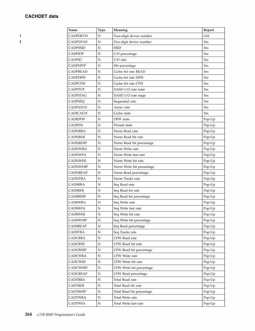
Name Type Meaning Report
CADPDEVN N Four-digit device number Util
CADPDVN5 N Five-digit device number Yes
CADPSSID N SSID Yes
CADPIOP N I/O percentage Yes
CADPIO N I/O rate Yes
CADPHITP N Hit percentage Yes
CADPREAD N Cache hit rate READ Yes
CADPDFW N Cache hit rate DFW Yes
CADPCFW N Cache hit rate CFW Yes
CADPTOT N DASD I/O rate total Yes
CADPSTAG N DASD I/O rate stage Yes
CADPSEQ N Sequential rate Yes
CADPASYN N Async rate Yes
CADICACH N Cache state Yes
CADIDFW N DFW state Pop-Up
CADIPIN N Pinned state Pop-Up
CADNRRA N Norm Read rate Pop-Up
CADNRHI N Norm Read hit rate Pop-Up
CADNRHIP N Norm Read hit percentage Pop-Up
CADNWRA N Norm Write rate Pop-Up
CADNWFA N Norm Write fast rate Pop-Up
CADNWHI N Norm Write hit rate Pop-Up
CADNWHIP N Norm Write hit percentage Pop-Up
CADNREAP N Norm Read percentage Pop-Up
CADNTRA N Norm Tracks rate Pop-Up
CADSRRA N Seq Read rate Pop-Up
CADSRHI N Seq Read hit rate Pop-Up
CADSRHIP N Seq Read hit percentage Pop-Up
CADSWRA N Seq Write rate Pop-Up
CADSWFA N Seq Write fast rate Pop-Up
CADSWHI N Seq Write hit rate Pop-Up
CADSWHIP N Seq Write hit percentage Pop-Up
CADSREAP N Seq Read percentage Pop-Up
CADSTRA N Seq Tracks rate Pop-Up
CADCRRA N CFW Read rate Pop-Up
CADCRHI N CFW Read hit rate Pop-Up
CADCRHIP N CFW Read hit percentage Pop-Up
CADCWRA N CFW Write rate Pop-Up
CADCWHI N CFW Write hit rate Pop-Up
CADCWHIP N CFW Write hit percentage Pop-Up
CADCREAP N CFW Read percentage Pop-Up
CADTRRA N Total Read rate Pop-Up
CADTRHI N Total Read hit rate Pop-Up
CADTRHIP N Total Read hit percentage Pop-Up
CADTWRA N Total Write rate Pop-Up
CADTWFA N Total Write fast rate Pop-Up
CACHDET data
264 z/OS RMF Programmer's Guide
||
||||

Name Type Meaning Report
CADTWHI N Total Write hit rate Pop-Up
CADTWHIP N Total Write hit percentage Pop-Up
CADTREAP N Total Read percentage Pop-Up
CADMDFWB N DFW bypass Pop-Up
CADMNICL N Non-cache ICL Pop-Up
CADMCWRI N CKD write Pop-Up
CADMRCRM N Read miss Pop-Up
CADMCFWB N CFW bypass Pop-Up
CADMNBYP N Non-cache bypass Pop-Up
CADMCHIT N CKD hits Pop-Up
CADMRCWP N Write prom Pop-Up
CADMDFWI N DFW inhibit Pop-Up
CACHSUM - Tabular report data table ERBCAST3RMF builds ERBCAST3 when using CACHSUM as a report type.
Name Type Meaning Report
CASDTLLN K Logical line number -
CASDTPSN K Sequence number -
CASPSSID N SSID Yes
CASPCUID N CUID Yes
CASPTYPM N Type-Mod Yes
CASPSIZE N Storage size Yes
CASPIO N I/O rate Yes
CASPHITP N Hit percentage Yes
CASPHIT N Hit rate Yes
CASPMTOT N Miss total rate Yes
CASPMSTG N Miss stage rate Yes
CASPREAP N Read percentage Yes
CASPSEQ N Sequential rate Yes
CASPASYN N Async rate Yes
CASPOFF N Off rate Yes
CASNRRA N Norm Read rate Pop-Up
CASNRHI N Norm Read hit rate Pop-Up
CASNRHIP N Norm Read hit percentage Pop-Up
CASNWRA N Norm Write rate Pop-Up
CASNWFA N Norm Write fast rate Pop-Up
CASNWHI N Norm Write hit rate Pop-Up
CASNWHIP N Norm Write hit percentage Pop-Up
CASNREAP N Norm Read percentage Pop-Up
CASNTRA N Norm Tracks rate Pop-Up
CASSRRA N Seq Read rate Pop-Up
CASSRHI N Seq Read hit rate Pop-Up
CASSRHIP N Seq Read hit percentage Pop-Up
CASSWRA N Seq Write rate Pop-Up
CASSWFA N Seq Write fast rate Pop-Up
CACHDET data
Chapter 8. Monitor III data reporter tables 265

Name Type Meaning Report
CASSWHI N Seq Write hit rate Pop-Up
CASSWHIP N Seq Write hit percentage Pop-Up
CASSREAP N Seq Read percentage Pop-Up
CASSTRA N Seq Tracks rate Pop-Up
CASCRRA N CFW Read rate Pop-Up
CASCRHI N CFW Read hit rate Pop-Up
CASCRHIP N CFW Read hit percentage Pop-Up
CASCWRA N CFW Write rate Pop-Up
CASCWHI N CFW Write hit rate Pop-Up
CASCWHIP N CFW Write hit percentage Pop-Up
CASCREAP N CFW Read percentage Pop-Up
CASTRRA N Total Read rate Pop-Up
CASTRHI N Total Read hit rate Pop-Up
CASTRHIP N Total Read hit percentage Pop-Up
CASTWRA N Total Write rate Pop-Up
CASTWFA N Total Write fast rate Pop-Up
CASTWHI N Total Write hit rate Pop-Up
CASTWHIP N Total Write hit percentage Pop-Up
CASTREAP N Total Read percentage Pop-Up
CASMCACH N Cache state Pop-Up
CASMCCON N Cache configured Pop-Up
CASMCAVL N Cache available Pop-Up
CASMCOFF N Cache offline Pop-Up
CASMCPIN N Cache pinned Pop-Up
CASMNVS N NVS state Pop-Up
CASMNCON N NVS configured Pop-Up
CASMNPIN N NVS pinned Pop-Up
CFACT - Tabular report data table ERBCFAT3RMF builds ERBCFAT3 when using CFACT as a report type.
Name Type Meaning Report
CFADTLLN K Logical line number -
CFADTPSN K Sequence number -
CFAPSTRU N Structure name Yes
CFAPTYPE N Structure type Yes
CFAPSTAT N Structure status Yes
CFAPSTEX N Structure status extension Util
CFAPENCR N Encryption indicator of CF structure Yes
CFAPSYS N System name Yes
CFAPSTEP N Structure execution % Util
CFAPUTIP N CPU utilization % Yes
CFAPSYNR N Sync rate Yes
CFAPASS N Sync average service time Yes
CFAPSYNC N Number of synchronous requests Util
CFAPASYR N Async rate Yes
CACHSUM data
266 z/OS RMF Programmer's Guide
||||

Name Type Meaning Report
CFAPAAS N Async average service time Yes
CFAPASYC N Number of asynchronous requests Util
CFAPACHG N Async changed % Yes
CFAPADEL N Async delay % Yes
CFAPQRT N Average queued request time Util
CFAPCNVC N Converted request count Util
CFAPDELC N Operation count delayed for dump serialization Util
CFAPQUEC N Queued operation count Util
CFAPMUSR N Maximum number of users Util
CFAPTUSR N Total number of users Util
CFAPPUSR N Number of problem users Util
CFAPREBP N Rebuild percentage Util
CFAINAM N Coupling facility name Yes
CFAISTRU N Structure name Pop-Up
CFAITYPE N Structure type Pop-Up
CFAICNAM N Connection name Pop-Up
CFAICJOB N Job name Pop-Up
CFAICSTA N Status Pop-Up
CFAICPRB N Problem status Util
CFAICASI N ASID Pop-Up
CFAICLVL N CF level Pop-Up
CFAICREB N User managed rebuild allowed Util
CFAICDRB N User managed rebuild with duplexing allowed Util
CFAICALT N Altering allowed Util
CFAICAUT N System managed processes allowed Util
CFAICSUS N Suspension of work is tolerated Util
CFAISTRS N Structure size Pop-Up
CFAISTRP N Structure size % Util
CFAISTUP N Structure utilized storage % Util
CFAISTRC N Structure storage class Util
CFAISTRM N Min structure size Util
CFAISTRX N Max structure size Util
CFAIDTS N Dump table size Util
CFAILDES N Data element size (LIST/LOCK only) Util
CFAILDLS N Data list entry size (LIST/LOCK only) Util
CFAILEL N List entries total (LIST/LOCK only) Pop-Up
CFAILEM N List entries current (LIST/LOCK only) Pop-Up
CFAIMAE N Data elements total (LIST only) Pop-Up
CFAICUE N Data elements current (LIST only) Pop-Up
CFAILTL N Lock entries total (LIST/LOCK only) Pop-Up
CFAILTM N Lock entries current (LIST/LOCK only) Pop-Up
CFAIDES N Data element size (CACHE only) Util
CFAIDEN N Directory entries total (CACHE only) Pop-Up
CFAIDEC N Directory entries current (CACHE only) Pop-Up
CFAICEN N Directory entries changed (CACHE only) Util
CFAIDEL N Data elements total (CACHE only) Pop-Up
CFACT data
Chapter 8. Monitor III data reporter tables 267

Name Type Meaning Report
CFAIDAC N Data elements current (CACHE only) Pop-Up
CFAICEL N Data elements changed (CACHE only) Util
CFAICONT N Contention % Pop-Up
CFAIFCON N False Contention % (LOCK only) Pop-Up
CFAIREQR N Request rate (CACHE only) Pop-Up
CFAIREAR N Read rate (CACHE only) Pop-Up
CFAIWRIR N Write rate (CACHE only) Pop-Up
CFAICAOR N Castout rate (CACHE only) Pop-Up
CFAIXIR N XI rate (CACHE only) Pop-Up
CFAIDER N Directory reclaims (CACHE only) Pop-Up
CFAIFCCL N First castout class Util
CFAILCCL N Last castout class Util
CFAIPREF N Allocation preference list Util
CFAIEXCL N Exclusion preference list Util
CFAISPCF N % of CF storage Pop-Up
CFAISAUM N Estimated Max. of Augmented Space (LIST only) Pop-Up
CFAISAUP N % Augmented Space Used (LIST only) Pop-Up
CFAISSCM N SCM Space Maximum (LIST only) Pop-Up
CFAISSCP N SCM Space % Used (LIST only) Pop-Up
CFAISLTM N SCM List Entries Est Max (LIST only) Pop-Up
CFAISLTC N SCM List Entries Current (LIST only) Pop-Up
CFAISLMM N SCM List Elements Est Max (LIST only) Pop-Up
CFAISLMC N SCM List Elements Current (LIST only) Pop-Up
CFAISALG N SCM Algorithm Type Pop-Up
CFOVER - Tabular report data table ERBCFOT3RMF builds ERBCFOT3 when using CFOVER as a report type.
Name Type Meaning Report
CFODTLLN K Logical line number -
CFODTPSN K Sequence number -
CFOPNAM N Coupling facility name Yes
CFOPMOD N Model Yes
CFOPVER N Version Yes
CFOPLVL N CF level Yes
CFOPDYND N CF dynamic dispatching Yes
CFOPSTAT N Status of CF Util
CFOPVOL N Volatility status Util
CFOPUTIP N Processor utilization % Yes
CFOPDEF N Processor defined Yes
CFOPPDED N Number of dedicated processors Util
CFOPPSHR N Number of shared processors Yes
CFOPPWGT N Average weighting of shared processors Yes
CFOPEFF N Processor effective Yes
CFOPREQR N Request rate Yes
CFOPTSD N Storage size Yes
CFACT data
268 z/OS RMF Programmer's Guide

Name Type Meaning Report
CFOPTSF N Storage available Yes
CFOPUTIS N Utilized storage % Util
CFOPTCS N Total control space Util
CFOPFCS N Free control space Util
CFOPDTS N Dump table control space Util
CFOPDTUS N Dump table in use Util
CFOPSYSC N Connected MVS system count Util
CFOPSTCI N Structure count in policy Util
CFOPSTCO N Structure count out policy Util
CFOPMNT N Maintenance mode active Util
CFOPRCV N Recovery manager active Util
CFOPSCMS N Storage Class Memory size Yes
CFOPSCMA N Storage Class Memory available Yes
CFOPSCMU N Utilized Storage Class Memory % Util
CFOPAUGS N Augmented space maximum Util
CFOPAUGA N Augmented space available Util
CFOPAUGU N % Utilized augmented space Util
CFOPSMSC N Sum of maximum storage class memory Util
CFSYS - Tabular report data table ERBCFST3RMF builds ERBCFST3 when using CFSYS as a report type.
Name Type Meaning Report
CFSDTLLN K Logical line number -
CFSDTPSN K Sequence number -
CFSPNAM N Coupling facility name Yes
CFSPSYS N System name Yes
CFSPSDEL N Subchannel delay % Yes
CFSPSBSP N Subchannel busy % Yes
CFSPPTHA N Paths available Yes
CFSPPDEL N Paths delay % Yes
CFSPSYNR N Sync rate Yes
CFSPASS N Sync average service time Yes
CFSPSYNC N Synchronous request count Util
CFSPSOPD N Average synchronous operation delay Util
CFSPSYNP N Synchronous request % Util
CFSPASYR N Async rate Yes
CFSPAAS N Async average service time Yes
CFSPASYC N Asynchronous request count Util
CFSPACHG N Async changed % Yes
CFSPADEL N Async delay % Yes
CFSPASYP N Asynchronous request % Util
CFSPREQC N Total request % Util
CFSPFOPT N Average failed operation time Util
CFSPCNVC N Synchronous to asynchronous conversion rate Util
CFSINAM N Coupling facility name Pop-Up
CFOVER data
Chapter 8. Monitor III data reporter tables 269
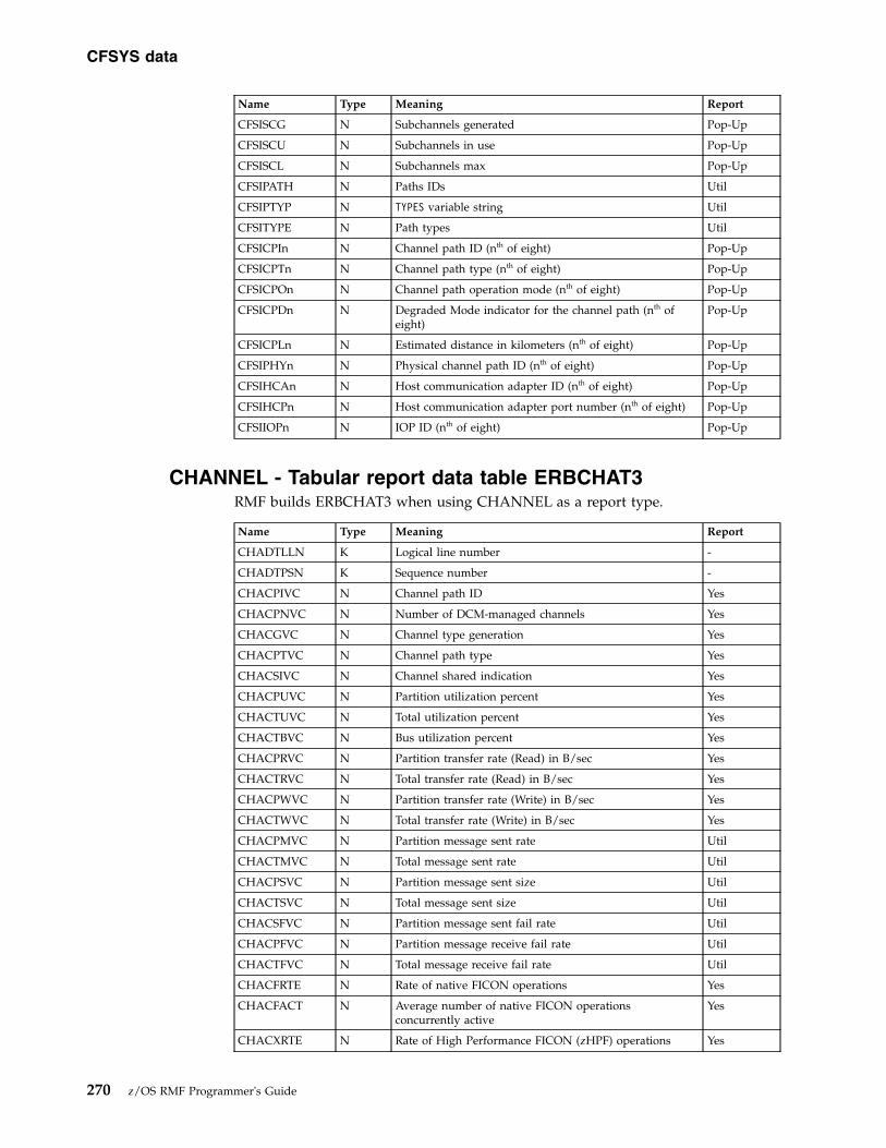
Name Type Meaning Report
CFSISCG N Subchannels generated Pop-Up
CFSISCU N Subchannels in use Pop-Up
CFSISCL N Subchannels max Pop-Up
CFSIPATH N Paths IDs Util
CFSIPTYP N TYPES variable string Util
CFSITYPE N Path types Util
CFSICPIn N Channel path ID (nth of eight) Pop-Up
CFSICPTn N Channel path type (nth of eight) Pop-Up
CFSICPOn N Channel path operation mode (nth of eight) Pop-Up
CFSICPDn N Degraded Mode indicator for the channel path (nth ofeight)
Pop-Up
CFSICPLn N Estimated distance in kilometers (nth of eight) Pop-Up
CFSIPHYn N Physical channel path ID (nth of eight) Pop-Up
CFSIHCAn N Host communication adapter ID (nth of eight) Pop-Up
CFSIHCPn N Host communication adapter port number (nth of eight) Pop-Up
CFSIIOPn N IOP ID (nth of eight) Pop-Up
CHANNEL - Tabular report data table ERBCHAT3RMF builds ERBCHAT3 when using CHANNEL as a report type.
Name Type Meaning Report
CHADTLLN K Logical line number -
CHADTPSN K Sequence number -
CHACPIVC N Channel path ID Yes
CHACPNVC N Number of DCM-managed channels Yes
CHACGVC N Channel type generation Yes
CHACPTVC N Channel path type Yes
CHACSIVC N Channel shared indication Yes
CHACPUVC N Partition utilization percent Yes
CHACTUVC N Total utilization percent Yes
CHACTBVC N Bus utilization percent Yes
CHACPRVC N Partition transfer rate (Read) in B/sec Yes
CHACTRVC N Total transfer rate (Read) in B/sec Yes
CHACPWVC N Partition transfer rate (Write) in B/sec Yes
CHACTWVC N Total transfer rate (Write) in B/sec Yes
CHACPMVC N Partition message sent rate Util
CHACTMVC N Total message sent rate Util
CHACPSVC N Partition message sent size Util
CHACTSVC N Total message sent size Util
CHACSFVC N Partition message sent fail rate Util
CHACPFVC N Partition message receive fail rate Util
CHACTFVC N Total message receive fail rate Util
CHACFRTE N Rate of native FICON operations Yes
CHACFACT N Average number of native FICON operationsconcurrently active
Yes
CHACXRTE N Rate of High Performance FICON (zHPF) operations Yes
CFSYS data
270 z/OS RMF Programmer's Guide

Name Type Meaning Report
CHACXACT N Average number of zHPF operations concurrently active Yes
CHACFDFR N Number of deferred native FICON operations per second Util
CHACXDFR N Number of deferred zHPF operations per second Util
CHACNET1 N Physical-network identifier (PNET ID) of first channelpath port
Util
CHACNET2 N Physical-network identifier (PNET ID) of second channelpath port
Util
CPC - Tabular report data table ERBCPCT3RMF builds ERBCPCT3 when using CPC as a report type.
Name Type Meaning Report
CPCDTLLN K Logical line number -
CPCDTPSN K Sequence number -
CPCPPNAM N Partition name Yes
CPCPDMSU N Defined capacity limit Yes
CPCPAMSU N Actual consumed MSUs Yes
CPCPCAPD N Hardware capping options of this partition (Y=yes,N=no)
Yes
CPCPCAPI N Initial capping (yes/no/mix) Util
CPCPHWCC N Absolute physical hardware capacity limit in numbers ofCPUs
Util
CPCPLPNO N Average number of logical processors or cores Yes
CPCPLEFU N Logical processor effective utilization % Yes
CPCPLTOU N Logical processor total utilization % Yes
CPCPPLMU N Physical LPAR utilization % Yes
CPCPPEFU N Physical processor effective utilization % Yes
CPCPPTOU N Physical processor total utilization % Yes
CPCPIND N Type/partition indicator No
CPCPLPND N Number of logical processors or cores defined Util
CPCPWGHT N Current weighting of shared CPU resources Util
CPCPDEDP N Number of dedicated processors online Util
CPCPLPSH N Percentage of the physical processor that a logicalprocessor of the LPAR is entitled to use. If HiperDispatchis active, this is the percentage of logical processors withmedium share.
Util
CPCPVCMH N If HiperDispatch is active, this is the number of logicalprocessors or cores with high share.
Util
CPCPVCMM N If HiperDispatch is active, this is the number of logicalprocessors or cores with medium share.
Util
CPCPVCML N If HiperDispatch is active, this is the number of logicalprocessors or cores with low share.
Util
CPCPOSNM N Operating system name Util
CPCPLPCN N LPAR cluster name Util
CPCPLCIW N Initial weight defined Util
CPCPLCMW N Minimum weight defined Util
CPCPLCXW N Maximum weight defined Util
CPCPCGNM N Group capacity name Util
CPCPCGLT N Group capacity limit Util
CHANNEL data
Chapter 8. Monitor III data reporter tables 271

Name Type Meaning Report
CPCPCGEM N Group minimum entitlement Util
CPCPCGEX N Group maximum entitlement Util
CPCPCSMB N Central storage in MB Util
CPCPUPID N User partition ID Util
CPCPHGNM N Hardware group name to which this partition belongs Util
CPCPHWGC N Absolute hardware group capping limit for members ofthe same hardware group in numbers of CPUs
Util
Fields in the CPC report header
Name Description of the variable Report
CPCHPNAM Name of partition that collected the data Yes
CPCHMOD Processor type Yes
CPCHMDL Processor model Yes
CPCHCMSU Effective CPC capacity (MSU/hour) Yes
CPCHCCAI Capacity adjustment indication Util
CPCHCCCR Capacity change reason Util
CPCHWF Weight % of Max Yes
CPCHLMSU 4h MSU average Yes
CPCHGNAM Capacity group name Yes
CPCHIMSU Image capacity Yes
CPCHCAP WLM capping % Yes
CPCHLMAX 4h MSU maximum Yes
CPCHGLIM Capacity group limit Yes
CPCHGL4H < 4h indicator for group Yes
CPCHAMSU Absolute MSU capping is active (Y / N) Yes
CPCHRMSU Time until capping Util
CPCHRGRP Time until capacity group is subject to capping Util
CPCHGAUN Capacity group average unused service units Util
CPCHCPU CPC sequence number Util
CPCHCPCN CPC name Util
CPCHCPNO Number of physical CPs Util
CPCHIFAN Number of physical ZAAPs Util
CPCHICFN Number of physical ICFs Util
CPCHIFLN Number of physical IFLs Util
CPCHSUPN Number of physical ZIIPs Util
CPCHPANO Number of configured LPARs Util
CPCHWAIT Wait completion indicator Util
CPCHPMSU % capacity used Util
CPCHDEDC Number of dedicated CPs across CPC Util
CPCHDEDA Number of dedicated ZAAPs across CPC Util
CPCHDEDI Number of dedicated ZIIPs across CPC Util
CPCHSHRC Number of shared physical CPs across CPC Util
CPCHSHRA Number of shared physical ZAAPs across CPC Util
CPCHSHRI Number of shared physical ZIIPs across CPC Util
CPCHCUTL % total physical utilization of shared CPs Util
CPC data
272 z/OS RMF Programmer's Guide

Name Description of the variable Report
CPCHAUTL % total physical utilization of shared ZAAPs Util
CPCHUUTL % total physical utilization of shared ZIIPs Util
CPCHLUTL % total physical utilization of shared ICFs Util
CPCHFUTL % total physical utilization of shared IFLs Util
CPCHVCPU VARYCPU option (YES/NO) Util
CPCHWMGT WLM management (YES/NO) Util
CPCHPRDS Multithreading IIP core productivity Yes
CPCHPRD Multithreading core productivity for general purpose processors Util
CPCHMCFS Multithreading Maximum Capacity Factor for IIP Util
CPCHMCF Multithreading Maximum Capacity Factor for general purposeprocessors
Util
CPCHMTMS Multithreading Mode for IIP Yes
CPCHMTM Multithreading Mode for general purpose processors Util
CPCHCFS Multithreading Capacity Factor for IIP Util
CPCHCF Multithreading Capacity Factor for general purpose processors Util
CPCHATDS Average Thread Density for IIP Util
CPCHATD Average Thread Density for general purpose processors Util
DELAY - Tabular report data table ERBJDET3RMF builds ERBJDET3 when using DELAY as a report type.
Name Type Meaning Report
JDEDTLLN K Logical line number -
JDEDTPSN K Sequence number -
JDELDAN N Jobname or summary Yes
JDETYPE N Class (A, B, E, O, S, or T) Util
JDETYPX N Class (A, B, E, O, S, or T) with possible extension O Yes
JDELDMN N Domain number; no longer used Yes
JDELPGN N Performance group number; no longer used Yes
JDEPSVCL N Service class name Yes
JDEGMIP N Indicator whether Storage Critical and/or CPU Critical(S, C, or SC)
Yes
JDELWFL N Work flow percentage Yes
JDELUSG N Using percentage Yes
JDELDEL N Delay percentage Yes
JDELIDL N Idle percentage Yes
JDELUKN N Unknown percentage Yes
JDELPROC N Processor delay percentage Yes
JDELDEV N Device delay percentage Yes
JDELSTOR N Storage delay percentage Yes
JDELSUBS N JES, HSM, and XCF delay percentage Yes
JDELOPER N Operator delay percentage Yes
JDELENQ N ENQ delay percentage Yes
JDELJES N JES delay percentage Util
JDELHSM N HSM delay percentage Util
JDELXCF N XCF delay percentage Util
CPC data
Chapter 8. Monitor III data reporter tables 273

Name Type Meaning Report
JDELMNT N Operator mount delay percentage Util
JDELMES N Operator message delay percentage Util
JDELQUI N Operator quiesce delay percentage Util
JDELREAS N Primary reason Yes
DEV - Tabular report data table ERBDEVT3RMF builds table ERBDEVT3 when using DEV as a report type.
Name Type Meaning Report
DEVDTLLN K Logical line number -
DEVDTPSN K Sequence number -
DEVPJOB N Jobname Yes
DEVPCLA N Class (A, B, O, S, or T) Yes
DEVPDMN N Domain number; no longer used Yes
DEVPPGN N Performance group number; no longer used Yes
DEVPSVCL N Service class name Yes
DEVPODEL N Overall delay percentage Yes
DEVPOUSE N Overall using percentage Yes
DEVPCON N Connect time Yes
DEV1SDEL N Delay percentage causes by volser1 Yes
DEV1VOLU N Volume serial number volser1 Yes
DEV2SDEL N Delay percentage caused by volser2 Yes
DEV2VOLU N Volume serial number volser2 Yes
DEV3SDEL N Delay percentage cause by volser3 Yes
DEV3VOLU N Volume serial number volser3 Yes
DEV4SDEL N Delay percentage caused by volser4 Yes
DEV4VOLU N Volume serial number volser4 Yes
DEVR - Tabular report data table ERBDVRT3RMF builds ERBDVRT3 when using DEVR as a report type.
Name Type Meaning Report
DVRDTLLN K Logical line number -
DVRDTPSN K Sequence number -
DVRPVOLU N Volser Yes
DVRPDEVN N Four-digit device number Util
DVRPDVN5 N Five-digit device number Yes
DVRPIDEN N Device indication (model) Yes
DVRPSTAT N Status Yes
DVRPEXP N Number of exposures Yes
DVRPACTV N Percentage of active time Yes
DVRPCONN N Percentage of connect time Yes
DVRPDISC N Percentage of disconnect time Yes
DVRPPEND N Percentage of pending time Util
DVRPDLYR N Pending delay reason header Yes
DVRPDLYP N Pending delay reason percentage Yes
DELAY data
274 z/OS RMF Programmer's Guide
||
||||

Name Type Meaning Report
DVRACTRT N Device activity rate Yes
DVRRESPT N Response Time Yes
DVRIOSQT N IOS queue time Util
DVRPDVBT N Percentage of device busy delay time Util
DVRPCUBT N Percentage of control unit busy delay time Util
DVRPSPBT N Percentage of director port busy delay time Util
DVRPJOBN N Jobname Yes
DVRPCLA N Class (A, B, O, S, or T) Yes
DVRPDMN N Domain number; no longer used Yes
DVRPPGN N Performance group number; no longer used Yes
DVRPSUSE N Percentage of using Yes
DVRPSDEL N Percentage of delay Yes
DVRPSVCL N Service class Yes
DVRPKIND N Device type indicator Util
DVRPLCUN N Logical control unit ID Util
DI - Tabular report data table ERBDSIT3RMF builds ERBDSIT3 when using DI as a report type.
Name Type Meaning Report
DSIDTLLN K Logical line number -
DSIDTPSN K Sequence number -
DSI1SID N System identifier Yes
DSI1DATE N Starting date Yes
DSI1TIME N Starting time Yes
DSI1DDNM N DD-name Yes
DSI1DSNM N Data set name Yes
DSI2DATE N Ending date Yes
DSI2TIME N Ending time Yes
DSI2MESS N Message field Yes
DSND - Tabular report data table ERBDNDT3RMF builds ERBDNDT3 when using DSND as a report type.
Name Type Meaning Report
DNDDTLLN K Logical line number -
DNDDTPSN K Sequence number -
DNDPDSN N Data set name Yes
DNDPVOLU N Volume serial Yes
DNDPJOBN N Jobname Yes
DNDPASID N ASID Yes
DNDPDUSG N DUSG (Using %) Yes
DNDPDDLY N DDLY (Delay %) Yes
DEVR data
Chapter 8. Monitor III data reporter tables 275

DSNJ - Tabular report data table ERBDNJT3RMF builds ERBDNJT3 when using DSNJ as a report type.
Name Type Meaning Report
DNJDTLLN K Logical line number -
DNJDTPSN K Sequence number -
DNJPASID N ASID Yes
DNJPDSN N Data set name Yes
DNJPVOLU N Volume Yes
DNJPDEVN N Four-digit device number Util
DNJPDVN5 N Five-digit device number Yes
DNJPDUSG N DUSG (Using %) Yes
DNJPDDLY N DDLY (Delay %) Yes
DSNV - Tabular report data table ERBDNVT3RMF builds ERBDNVT3 when using DSNV as a report type.
Name Type Meaning Report
DNVDTLLN K Logical line number -
DNVDTPSN K Sequence number -
DNVPDSN N Data set name Yes
DNVPJOBN N Jobname Yes
DNVPASID N ASID Yes
DNVPDUSG N DUSG (Using %) Yes
DNVPDDLY N DDLY (Delay %) Yes
ENCLAVE - Tabular report data table ERBENCT3RMF builds ERBENCT3 when using ENCLAVE as a report type.
Name Type Meaning Report
ENCDTLLN K Logical line number -
ENCDTPSN K Sequence number -
ENCENAME N Enclave name (generated) Yes
ENCCLASS N Service class Yes
ENCGOAL N Goal time Yes
ENCGPERC N Goal percent Yes
ENCPER N Period Yes
ENCDENC N Dependent enclave indicator Yes
ENCXENC N Multi-system enclave indicator Yes
ENCTCPU N Total CPU time (seconds) Yes
ENCTIFA N Total ZAAP time (seconds) Util
ENCTIFC N Total ZAAP on CP time (seconds) Util
ENCDCPU N Delta CPU time (seconds) Pop-Up
ENCDIFA N Delta ZAAP time (seconds) Util
ENCDIFC N Delta ZAAP on CP time (seconds) Util
ENCDCPUP N Delta CPU percentage in Monitor III range Yes
ENCDIFAP N Delta ZAAP percentage Util
DSNJ data
276 z/OS RMF Programmer's Guide
||
||||

Name Type Meaning Report
ENCDIFCP N Delta ZAAP on CP percentage Util
ENCSAMP N Total execution samples Pop-Up
ENCTUSG N % Total using samples Yes
ENCTDLY N % Total delay samples Yes
ENCIDLE N % Idle Yes
ENCCUSG N % CPU using Pop-Up
ENCIFAU N % ZAAP using Pop-Up
ENCIFCU N % ZAAP on CP using Util
ENCCDLY N % CPU delay Pop-Up
ENCIUSG N % I/O using Pop-Up
ENCIDLY N % I/O delay Pop-Up
ENCIFAD N % ZAAP delay Pop-Up
ENCCCAP N % CPU capping Pop-Up
ENCSTOR N % Storage delay Pop-Up
ENCUNKN N % Unknown Pop-Up
ENCQUED N % Queue delay Pop-Up
ENCESTYP N Subsystem type Pop-Up
ENCEOWNM N Owner name Pop-Up
ENCEOSYS N Owner system Pop-Up
ENCXTOKN N Export token Pop-Up
ENCATTN N Number of attributes in table Pop-Up
ENCATT00 N Used to place selected attributes to report, truncated to alength of eight characters
Yes
ENCATT01 N Accounting Information Pop-Up
ENCATT02 N Collection Name Pop-Up
ENCATT03 N Connection Type Pop-Up
ENCATT04 N Correlation Information Pop-Up
ENCATT05 N LU Name Pop-Up
ENCATT06 N Net ID Pop-Up
ENCATT07 N Package Name Pop-Up
ENCATT08 N Plan Name Pop-Up
ENCATT09 N Procedure Name Pop-Up
ENCATT10 N Process Name Pop-Up
ENCATT11 N Scheduling Environment Pop-Up
ENCATT12 N Subsystem Collection Name Pop-Up
ENCATT13 N Subsystem Instance Pop-Up
ENCATT14 N Subsystem Parameter Pop-Up
ENCATT15 N Subsystem Type Pop-Up
ENCATT16 N Transaction/Job Class Pop-Up
ENCATT17 N Transaction/Job Name Pop-Up
ENCATT18 N User ID Pop-Up
ENCATT19 N Priority Pop-Up
ENCATT20 N Client IP Address Pop-Up
ENCATT21 N Client User ID Pop-Up
ENCATT22 N Client Transaction Name Pop-Up
ENCATT23 N Client Workstation/Host name Pop-Up
ENCLAVE data
Chapter 8. Monitor III data reporter tables 277
Name Type Meaning Report
ENCATT24 N Client Accounting Information Pop-Up
ENCTSUP N Total ZIIP time (seconds) Pop-Up
ENCTSUC N Total ZIIP on CP time (seconds) Util
ENCDSUP N Delta ZIIP time (seconds) Pop-Up
ENCDSUC N Delta ZIIP on CP time (seconds) Util
ENCDSUPP N Delta ZIIP percentage Util
ENCDSUCP N Delta ZIIP on CP percentage Util
ENCSUPU N % ZIIP using Pop-Up
ENCSUCU N % ZIIP on CP using Util
ENCSUPD N % ZIIP delay Pop-Up
ENQ - Tabular report data table ERBENQT3RMF builds ERBENQT3 when using ENQ as a report type.
Name Type Meaning Report
ENQDTLLN K Logical line number -
ENQDTPSN K Sequence number -
ENQPWJOB N Jobname of waiting job Yes
ENQPODEL N Overall delay percentage Yes
ENQPRDEL N Percentage of delay for the resource Yes
ENQPWSTT N Status of waiting job Yes
ENQPMAJS N Resource major name and scope or minor name Yes
ENQPHDEL N Holding percentage for the holding job Yes
ENQPHJOB N Jobname of holding job or system name for holding job Yes
ENQPHSTT N Status for the holding job Yes
ENQR - Tabular report data table ERBEQRT3RMF builds ERBEQRT3 when using ENQR as a report type.
Name Type Meaning Report
EQRDTLLN K Logical line number -
EQRDTPSN K Sequence number -
EQRPMAJS N Resource major name and scope or resource minor name Yes
EQRPRDEP N Percentage of delay for the delayed job Yes
EQRPWJOB N Jobname of delayed job Yes
EQRPWSTT N Status of delayed job Yes
EQRPHDEP N Holding percentage for the holding job Yes
EQRPHJOB N Jobname of holding job or system name Yes
EQRPHSTT N Status of holding job Yes
HSM - Tabular report data table ERBHSMT3RMF builds ERBHSMT3 when using HSM as a report type. The table variables areidentical to the variables of the ERBJEST3 table; see the ERBJEST3 table for moreinformation.
ENCLAVE data
278 z/OS RMF Programmer's Guide

IOQUEUE - Tabular report data table ERBIOQT3RMF builds ERBIOQT3 when using IOQUEUE as a report type.
Name Type Meaning Report
IOQDTLLN K Logical line number -
IOQDTPSN K Sequence number -
IOQCPIVC N Channel path ID Yes
IOQPATVC N Path attributes Util
IOQDCMVC N DCM-managed channels Yes
IOQPCUVC N Physical CU string Yes
IOQMMNVC N Minimum number of DCM-managed channels used Yes
IOQMMXVC N Maximum number of DCM-managed channels used Yes
IOQMDFVC N Defined number of DCM-managed channels Yes
IOQLCUVC N Logical control unit ID Yes
IOQCRTVC N Contention rate Yes
IOQDQLVC N Delay queue length Yes
IOQCPTVC N Channel path ID taken Yes
IOQSPBVC N Director port busy percent Yes
IOQCUBVC N Control unit busy percent Yes
JES - Tabular report data table ERBJEST3RMF builds ERBJEST3 when using JES as a report type.
Name Type Meaning Report
HJSDTLLN K Logical line number -
HJSDTPSN K Sequence number -
HJSPJOB N Jobname Yes
HJSPODEL N Overall delay percentage Yes
HJS1FDEL N Delay percentage Yes
HJS1FCNR N Function code Yes
HJS1EXPL N Explanation Yes
HJS2FDEL N Delay percentage Util
HJS2FCNR N Function code Util
HJS2EXPL N Explanation Util
JOB - Tabular report data table ERBJDJT3RMF builds ERBJDJT3 when using JOB as a report type.
Name Type Meaning Report
JDJDTLLN K Logical line number -
JDJDTPSN K Sequence number -
JDJLDAN N Jobname or summary Yes
JDJLASID N Address space identification Yes
JDJCLASS N Class (A, B, E, O, S, or T) Util
JDJCLASX N Class (A, B, E, O, S, or T) with possible extension O Yes
JDJLDMN N Domain number; no longer used Yes
JDJLPGN N Performance group number; no longer used Yes
IOQUEUE data
Chapter 8. Monitor III data reporter tables 279

Name Type Meaning Report
JDJPSVCL N Service class name Yes
JDJLWFL N Work flow percentage Yes
JDJLUSP N Processor using percentage Yes
JDJLUSD N Device using percentage Yes
JDJLUSG N Using percentage Util
JDJLDEL N Delay percentage Yes
JDJLIDL N Idle percentage Yes
JDJLUKN N Unknown percentage Yes
JDJLPROC N Processor delay percentage Yes
JDJLDEV N Device delay percentage Yes
JDJLSTOR N Storage delay percentage Yes
JDJLSUBS N SUBS delay percentage Yes
JDJLOPER N Operator delay percentage Yes
JDJLENQ N ENQ delay percentage Yes
JDJLJES N JES delay percentage Util
JDJLHSM N HSM delay percentage Util
JDJLXCF N XCF delay percentage Util
JDJLMNT N Operator mount delay percentage Util
JDJLMES N Operator message delay percentage Util
JDJLQUI N Operator quiesce delay percentage Util
JDJLREAS N Primary reason Yes
LOCKSP - Tabular report data table ERBLSPT3RMF builds ERBLSPT3 when using LOCKSP as a report type.
Name Type Meaning Report
LSPDTLLN K Logical line number -
LSPDTPSN K Sequence number -
LSPPRES N Resource name Yes
LSPPJT N Spinner jobname / spin lock type Yes
LSPPAC N Spinner address space ID / CPU ID Yes
LSPPRAD N Spinner request address Yes
LSPPHELD N Spin lock held percentage Yes
LSPPSPIN N Spin percentage Yes
LOCKSU - Tabular report data table ERBLSUT3RMF builds ERBLSUT3 when using LOCKSU as a report type.
Name Type Meaning Report
LSUDTLLN K Logical line number -
LSUDTPSN K Sequence number -
LSUPRES N Resource name Yes
LSUPTYPE N Lock Type Yes
LSUPJOB N Holder job name Yes
LSUPASI N Holder address space ID Yes
LSUPRAD N Request address Yes
JOB data
280 z/OS RMF Programmer's Guide

Name Type Meaning Report
LSUPHELD N Holding percentage Yes
LSUPINTR N Holding while interrupted percentage Yes
LSUPDISP N Holding while dispatched percentage Yes
LSUPSUSP N Holding while suspended percentage Yes
OPD - Tabular report data table ERBOPDT3RMF builds ERBOPDT3 when using OPD as a report type.
Name Type Meaning Report
OPDDTLLN K Logical line number -
OPDDTPSN K Sequence number -
OPDPJOBN N Jobname Yes
OPDPUSEN N User name Yes
OPDPASID N ASID Yes
OPDPASIX N Hexadecimal ASID Yes
OPDPPRID N Process ID Yes
OPDPPPID N Parent's process ID Yes
OPDPLATW N Waiting for process latch Yes
OPDPSTAT N Process state Yes
OPDPAPPL N Percentage of TCB and SRB time Yes
OPDPTOT N Total computing time since process has been started Yes
OPDPSERV N Server type Yes
OPDIPRID N Process ID Pop-Up
OPDIPPID N Parent's process ID Pop-Up
OPDIJOBN N Jobname Pop-Up
OPDIUSEN N User name Pop-Up
OPDIASID N ASID Pop-Up
OPDIASIX N Hexadecimal ASID Pop-Up
OPDITIMD N Start time/date Pop-Up
OPDIAPPL N Percentage of TCB and SRB time Pop-Up
OPDITOT N Total computing time since process has been started Pop-Up
OPDILPID N Latch process ID the process is waiting for (0 = notwaiting)
Pop-Up
OPDICMD N Command buffer Pop-Up
OPDISERN N Server name Pop-Up
OPDISERV N Server type Pop-Up
OPDIACTF N Number of active files Pop-Up
OPDIMAXF N Maximum files Pop-Up
OPDISTAT N Process state Pop-Up
OPDISTA1 N 1. possible state Pop-Up
OPDISTA2 N 2. possible state Pop-Up
OPDISTA3 N 3. possible state Pop-Up
LOCKSP data
Chapter 8. Monitor III data reporter tables 281

PCIE – Tabular report data table ERBPCIT3RMF builds ERBPCIT3 when using PCIE as a report type.
Name Type Meaning Report
PCIDTLLN K Logical line number -
PCIDTPSN K Sequence number -
PCIEPFID N PCIE function id Yes
PCIESTAT N Function status Yes
PCIEPCID N Physical channel id Yes
PCIEDEVT N Device type Yes
PCIEALLT N Function alloc time % Yes
PCIEJOBN N Owning job name Yes
PCIEASID N Owning ASID Yes
PCIELOOP N PCI Load operations rate (RoCE, ISM function, HardwareAccelerator)
Yes
PCIESTOP N PCI Store operations rate (RoCE, ISM function, HardwareAccelerator)
Yes
PCIESBOP N PCI Store Block operations rate (RoCE, ISM function,Hardware Accelerator)
Yes
PCIERFOP N PCI Refresh operations rate (RoCE, ISM function,Hardware Accelerator)
Yes
PCIEDMAR N Transfer read rate (Synchronous I/O, RoCE, HardwareAccelerator)
Yes, Pop-Up
PCIEDMAW N Transfer write rate Yes, Pop-Up
PCIEDPKR N Received packets rate (RoCE, Synchronous I/O) Pop-Up
PCIEDPKT N Transmitted packets rate (RoCE, Synchronous I/O) Pop-Up
PCIEDWUP N Work unit rate (Hardware Accelerator) Pop-Up
PCIEDAUT N Adapter utilization (Hardware Accelerator) Pop-Up
PCIEADAT N Allocation date Pop-Up
PCIEATIM N Allocation time Pop-Up
PCIEDMAN N Number of DMA address spaces Util
PCIEFTYP N Hardware Accelerator application type Util
PCIEFBSY N Time busy % (Hardware Accelerator, Synchronous I/O) Pop-Up
PCIEFTR N Hardware Accelerator transfer rate Util
PCIEFRET N Request execution time (Hardware Accelerator) Pop-Up
PCIEFRES N Request execution time standard deviation (HardwareAccelerator)
Pop-Up
PCIEFRQT N Request queue time (Hardware Accelerator) Pop-Up
PCIEFRQS N Request queue time standard deviation (HardwareAccelerator)
Pop-Up
PCIEFRSZ N Request size (Hardware Accelerator) Pop-Up
PCIE1RRC N Application request rate compression (HardwareAccelerator)
Pop-Up
PCIE1TPC N Application throughput compression (HardwareAccelerator)
Pop-Up
PCIE1RCC N Application ratio compression (Hardware Accelerator) Pop-Up
PCIE1RRD N Application request rate de-compression (HardwareAccelerator)
Pop-Up
PCIE1TPD N Application throughput de-compression (HardwareAccelerator)
Pop-Up
PCIE1RCD N Application ratio de-compression (Hardware Accelerator) Pop-Up
PCIE data
282 z/OS RMF Programmer's Guide
||
||
||
||
|||
|
||
||
||
||
|
|
|
||
|
||
|
||
||
|
||
||
|

Name Type Meaning Report
PCIE1BPS N Buffer pool memory size (Hardware Accelerator) Pop-Up
PCIE1BPU N Buffer pool utilization % (Hardware Accelerator) Pop-Up
PCIENET1 N Physical-network identifier (PNET ID) that identifies thefirst port of the RoCE device or ISM function
Pop-Up
PCIENET2 N Physical-network identifier (PNET ID) that identifies thesecond port of the RoCE device
Pop-Up
PCIEPOID N Port ID (RoCE, ISM function, Synchronous I/O) Pop-Up
PCIESERN N Serial number of the storage controller (SynchronousI/O)
Pop-Up
PCIETYMO N Type and model of the storage controller (SynchronousI/O)
Pop-Up
PCIETBPC N Time busy % (CPC) (Synchronous I/O) Pop-Up
PCIERRT N Request rate (Synchronous I/O) Pop-Up
PCIERRTC N Request rate (CPC) (Synchronous I/O) Pop-Up
PCIETRRC N Transfer read rate (CPC) (Synchronous I/O) Pop-Up
PCIEXRR N Transfer read ratio (Synchronous I/O) Pop-Up
PCIEXRRC N Transfer read ratio (CPC) (Synchronous I/O) Pop-Up
PCIETWRC N Transfer write rate (CPC) (Synchronous I/O) Pop-Up
PCIEXWR N Transfer write ratio (Synchronous I/O) Pop-Up
PCIEXWRC N Transfer write ratio (CPC) (Synchronous I/O) Pop-Up
PCIESRR N Successful request % (Synchronous I/O) Pop-Up
PCIESRRC N Successful request % (CPC) (Synchronous I/O) Pop-Up
PROC - Tabular report data table ERBPRCT3RMF builds ERBPRCT3 when using PROC as a report type.
Name Type Meaning Report
PRCDTLLN K Logical line number -
PRCDTPSN K Sequence number -
PRCPJOB N Jobname Yes
PRCPASI N Address space ID of the job (decimal format) Util
PRCPCLA N Class (A, B, E, O, S, or T) Util
PRCPCLAX N Class (A, B, E, O, S, or T) with possible extension O Yes
PRCPDMN N Domain number; no longer used Yes
PRCPPGN N Performance group number; no longer used Yes
PRCPSVCL N Service class name Yes
PRCPODEL N Overall delay percentage for this address space. Util
PRCPOUSE N Overall using percentage for this address space. Util
PRCPTYPE N Processor type Yes
PRCPTST N Overall application percentage for this address space. Util
PRCPCAP N Capping delay percentage Util
PRCPETST N Overall application percentage including EApplpercentage
Util
PRCPAPPL N Overall application percentage on behalf of this addressspace and processor type
Util
PRCPEAPP N Overall application percentage including EApplpercentage on behalf of this address space and processortype
Yes
PCIE data
Chapter 8. Monitor III data reporter tables 283
|
|
||
|
|
|
|
|
|
|
|
|
|
|
|
|
|
|

Name Type Meaning Report
PRCPTWFL N Overall workflow percentage of this address space andprocessor type
Util
PRCPTDEL N Overall delay percentage for this address space andprocessor type
Yes
PRCPTUSE N Overall using percentage for this address space andprocessor type
Yes
PRCPAACP N % ZAAP on CP using Util
PRCPIICP N % ZIIP on CP using Util
PRC1SDEL N Delay percentage caused by jobname1 Yes
PRC1JOBN N Jobname1 Yes
PRC2SDEL N Delay percentage caused by jobname2 Yes
PRC2JOBN N Jobname2 Yes
PRC3SDEL N Delay percentage caused by jobname3 Yes
PRC3JOBN N Jobname3 Yes
PRCTCPUT N Total CPU time (milliseconds) Util
PROCU - Tabular report data table ERBPRUT3RMF builds ERBPRUT3 when using PROCU as a report type.
Name Type Meaning Report
PRUDTLLN K Logical line number -
PRUDTPSN K Sequence number -
PRUPJOB N Jobname Yes
PRUPASI N Address space ID of the job (decimal format) Yes
PRUPCLA N Class (A, B, E, O, S, or T) Util
PRUPCLAX N Class (A, B, E, O, S, or T) with possible extension O Yes
PRUPSVCL N Service class name Yes
PRUPCLP N Service class period Util
PRUPCPT N Time on CP % Yes
PRUPAACT N ZAAP time on CP % Yes
PRUPIICT N ZIIP time on CP % Yes
PRUPCPE N CP EAppl % Yes
PRUPAAPE N ZAAP EAppl % Yes
PRUPIIPE N ZIIP EAppl % Yes
PRUPTOTC N Percentage of total accumulated CPU time as sum of TCBtime, global and local SRB time and preemptable or clientSRB time, consumed on behalf of this address space.
Util
PRUPTOTE N Percentage of total accumulated CPU time as sum of TCBtime, global and local SRB time, preemptable or clientSRB time, and enclave time consumed within thisaddress space.
Util
PRUPTCB N Percentage of TCB time consumed in this address space. Util
PRUPSRB N Percentage of SRB time consumed in this address spaceby local or global SRBs.
Util
PRUPPCS N Percentage of preemptable or client SRB time consumedon behalf of this address space.
Util
PRUPEPS N Percentage of preemptable or client SRB and enclave CPUtime consumed within this address space.
Util
PRUTCPUT N Total CPU time (milliseconds) Util
PROC data
284 z/OS RMF Programmer's Guide

RLSDS - Tabular report data table ERBVRDT3RMF builds ERBVRDT3 when using RLSDS as a report type.
Name T Description of the variable Report
VRDDTLLN K Logical line number -
VRDDTPSN K Sequence number -
VRDPNAM N VSAM sphere name, Data set name, MVS system name,Access type, Response time, Read rate, Read BMF hitpercentage, Read CF hit percentage
Yes
VRDPRDAS N Read DASD hit percentage Yes
VRDPBMFV N BMF valid percentage Yes
VRDPBMFF N BMF false invalid percentage Yes
VRDPWRTE N Write rate Yes
VRDPCALO N Castout lock percentage Util
VRDPREDA N Redo activity percentage Util
VRDPRRED N Recursive redo percentage Util
VRDPIND N Report indication Util
RLSLRU - Tabular report data table ERBVRLT3RMF builds ERBVRLT3 when using RLSLRU as a report type.
Name T Description of the variable Report
VRLDTLLN K Logical line number -
VRLDTPSN K Sequence number -
VRLPSYS N MVS system name Yes
VRLPACT N Average CPU time Yes
VRLPBSG N Buffer size goal Yes
VRLPBSH N Buffer size high Yes
VRLPBSO N Buffer percentage accelerated Yes
VRLPBSS N Buffer percentage reclaiming Yes
VRLPABMF N Average BMF hit percentage Yes
VRLPACAC N Average Cache hit percentage Yes
VRLPADAS N Average DASD hit percentage Yes
VRLPCALO N Castout lock percentage Util
VRLPREDA N Redo activity percentage Util
VRLPRRED N Recursive redo percentage Util
VRLISYS N MVS system name Pop-Up
VRLIFPL N Fixed pages low Pop-Up
VRLIFPH N Fixed pages high Pop-Up
VRLIFPA N Fixed pages average Pop-Up
VRLIFIXS N Fixed storage Pop-Up
VRLIRSP N Real storage % Pop-Up
VRLILSn N Buffer count by pool of size nK, low value, below 2 GB,where n is 2, 4, ..., 32,
Pop-Up
VRLIHSn N Buffer count by pool of size nK, high value, below 2 GB,where n is 2, 4, ..., 32,
Pop-Up
VRLICSn N Buffer count by pool of size nK, average value, below 2GB, where n is 2, 4, ..., 32
Pop-Up
VRLAFPL N Fixed pages low above 2 GB Pop-Up
RLSDS data
Chapter 8. Monitor III data reporter tables 285

Name T Description of the variable Report
VRLAFPH N Fixed pages high above 2 GB Pop-Up
VRLAFPA N Fixed pages average above 2 GB Pop-Up
VRLAFIXS N Fixed storage above 2 GB Pop-Up
VRLARSP N Real storage % above 2 GB Pop-Up
VRLALSn N Buffer count by pool of size nK, low value, above 2 GB,where n is 2, 4, ..., 32,
Pop-Up
VRLAHSn N Buffer count by pool of size nK, high value, above 2 GB,where n is 2, 4, ..., 32,
Pop-Up
VRLACSn N Buffer count by pool of size nK, average value, above 2GB, where n is 2, 4, ..., 32,
Pop-Up
RLSSC - Tabular report data table ERBVRST3RMF builds ERBVRST3 when using RLSSC as a report type.
Name T Description of the variable Report
VRSDTLLN K Logical line number -
VRSDTPSN K Sequence number -
VRSPNAM N Storage class name, MVS system name, CF structurename, Access type
Yes
VRSPRTIM N Average response time Yes
VRSPRRTE N Read rate Yes
VRSPRBMF N Read BMF hit percentage Yes
VRSPRCF N Read CF hit percentage Yes
VRSPRDAS N Read DASD hit percentage Yes
VRSPBMFV N BMF valid percentage Yes
VRSPBMFF N BMF false invalid percentage Yes
VRSPWRTE N Write rate Yes
VRSPIND N Report indication Util
SCM - Tabular report data table ERBSCMT3
RMF builds ERBSCMT3 when using SCM as a report type.
Name Type Meaning Report
SCMDTLLN K Logical line number -
SCMDTPSN K Sequence number -
SCMRPID N Card id Yes
SCMUTL N LPAR utilization percentage Yes
SCMUTLC N Total utilization percentage Yes
SCMDRD N LPAR bytes read per second Yes
SCMDRDC N Total bytes read per second Yes
SCMDWR N LPAR bytes written per second Yes
SCMDWRC N Total bytes written per second Yes
SCMQR N LPAR requests processed per second Yes
SCMQRC N Total requests processed per second Yes
SCMART N LPAR response time per request in milliseconds Yes
SCMARTC N Total response time per request in milliseconds Yes
RLSLRU data
286 z/OS RMF Programmer's Guide

Name Type Meaning Report
SCMAQTC N Total IOP queue time per request in milliseconds Yes
SCMTRQ N LPAR number of requests Util
SCMTRQC N Total number of requests Util
SCMHSCR N Number of SSCH instructions to all EADM devices persecond
Yes
SCMHSCH N Total number of SSCH instructions to all EADM devices Yes
SCMHFPT N Function pending time across all EADM devices inmilliseconds
Yes
SCMHIQT N IOP queue time across all EADM devices in milliseconds Yes
SCMHCRT N Command response time across all EADM devices inmilliseconds
Yes
Fields in the SCM report header
Name Type Meaning Report
SCMHSCR N Number of SSCH instructions to all EADM devices persecond
Yes
SCMHSCH N Total number of SSCH instructions to all EADM devices Yes
SCMHFPT N Function pending time across all EADM devices inmilliseconds
Yes
SCMHIQT N IOP queue time across all EADM devices in milliseconds Yes
SCMHCRT N Command response time across all EADM devices inmilliseconds
Yes
SPACED - Tabular report data table ERBSPDT3RMF builds ERBSPDT3 when using SPACED as a report type.
Name T Description of the variable Report
SPDDTLLN K Logical line number -
SPDDTPSN K Sequence number -
SPDPVOL N Volume Yes
SPDPTSP N Total capacity in MB Yes
SPDPFSP N Free space in MB Yes
SPDPFSR N Free space percentage Yes
SPDPLBK N Largest block in MB Yes
SPDPSGN N Storage group name Yes
SPACEG - Tabular report data table ERBSPGT3RMF builds ERBSPGT3 when using SPACEG as a report type.
Name T Description of the variable Report
SPGDTLLN K Logical line number -
SPGDTPSN K Sequence number -
SPGPSGN N Storage Group Yes
SPGPTSP N Total capacity in MB Yes
SPGPFSP N Free space in MB Yes
SPGPFSR N Free space percentage Yes
SPGPNVO N Number of Volumes Yes
SCM data
Chapter 8. Monitor III data reporter tables 287

STOR - Tabular report data table ERBSTRT3RMF builds ERBSTRT3 when using STOR as a report type.
Name T Description of the variable Report
STRDTLLN K Logical line number -
STRDTPSN K Sequence number -
STRPJOB N Jobname Yes
STRPCLA N Class (A, B, O, S, or T) Yes
STRPDMN N Domain number; no longer used Yes
STRPPGN N Performance group number; no longer used Yes
STRPSVCL N Service class name Yes
STRPODEL N Overall delay percentage Yes
STR1SDEL N Delay percentage COMM Yes
STR2SDEL N Delay percentage local Yes
STR3SDEL N Delay percentage VIO Util
STR4SDEL N Delay percentage SWAP Yes
STR5SDEL N Delay percentage OUTR Yes
STR6SDEL N Cross memory delay % Util
STR7SDEL N Hiperspace delay % Util
STR8SDEL N Other delays % (including VIO, XMEM and HIPR) Yes
STRPACTV N Average ACTV frames Util
STRPFIXD N Average fixed frames total Util
STRPIDLE N Average IDLE frames Util
STRPWSET N Average working set frames Yes
STRPWSEX N Average ES working set frames Yes
STORC - Tabular report data table ERBCSUT3RMF builds ERBCSUT3 when using STORC as a report type.
Name T Description of the variable Report
CSUDTLLN K Logical line number -
CSUDTPSN K Sequence number -
CSXNAME N Jobname Yes
CSXACT N Active column Yes
CSXCLA N Class (A, B, O, S, or T) Yes
CSXDMN N Domain number; no longer used Yes
CSXPGN N Performance group number; no longer used Yes
CSXCSN N Service class name Yes
CSXASID N Address space identifier Yes
CSXTIME N Elapsed time Yes
CSXPCSA N Percentage of CSA Yes
CSXPECS N Percentage of ECSA Yes
CSXPSQA N Percentage of SQA Yes
CSXPESQ N Percentage of ESQA Yes
CSXACSA N Amount of CSA Yes
CSXAECS N Amount of ECSA Yes
SPACEG data
288 z/OS RMF Programmer's Guide

Name T Description of the variable Report
CSXASQA N Amount of SQA Yes
CSXAESQ N Amount of ESQA Yes
CSXJESID N JES identifier Util
CSXTDATE N Termination date Util
CSXTTIME N Termination time Util
STORCR - Tabular report data table ERBCRST3RMF builds ERBCRST3 when using STORCR as a report type.
Name T Description of the variable Report
CSUDTLLN K Logical line number -
CSUDTPSN K Sequence number -
CSXNAME N Jobname Yes
CSXJESID N JES identifier Yes
CSXTDATE N Termination date Yes
CSXTTIME N Termination time Yes
CSXACSA N Amount of CSA Yes
CXSAECS N Amount of ECSA Yes
CSXASQA N Amount of SQA Yes
CSXAESQ N Amount of ESQA Yes
STORF - Tabular report data table ERBSTFT3RMF builds ERBSTFT3 when using STORF as a report type.
Name Type Meaning Report
STFDTLLN K Logical line number -
STFDTPSN K Sequence number -
STFPJOB N Jobname Yes
STFPCLA N Class (A, B, O, S, or T) Yes
STFPDMN N Domain number; no longer used Yes
STFPPGN N Performance group number; no longer used Yes
STFPSVCL N Service class name Yes
STFPTOTL N Frame occupancy TOTAL Yes
STFPACTV N Frame occupancy ACTV Yes
STFPIDLE N Frame occupancy IDLE Yes
STFPWSET N Active frames WSET Yes
STFPFIXD N Active frames FIXED Yes
STFPDIV N Active frames DIV Yes
STFPAUXS N Auxiliary storage slots Yes
STFPPGIN N Page-in Rate Yes
STFPEXIN N Page-in rate from expanded storage Util
STFPSPPI N Shared pages page-in rate from auxiliary storage Util
STFPTOTS N Total number of shared page views Util
STFPSVIN N Total number of valid shared pages Util
STFPSPVL N Shared pages validation rate Util
STORC data
Chapter 8. Monitor III data reporter tables 289

Name Type Meaning Report
STFPLMO N Number of fixed 1 MB memory objects allocated Util
STFPLPR N Number of 1 MB frames fixed in real storage Util
STFPFREM N Number of freemained frames Util
STFPGMO N Number of 2 GB memory objects allocated Util
STFPGPR N Number of 2 GB frames fixed in central storage Util
STORM - Tabular report data table ERBSTMT3RMF builds ERBSTMT3 when using STORM as a report type.
Name Type Meaning Report
STMDTLLN K Logical line number -
STMDTPSN K Sequence Number -
STMPJOB N Jobname Yes
STMPASI N Address space identifier Yes
STMPCLA N Class (A, B, O, S, or T) Yes
STMPSVCL N Service class name Yes
STMPCLP N Service class period Util
STMPTMO N Average number of memory objects allocated (by thisaddress space)
Yes
STMPCMO N Average number of high virtual common memory objectsallocated (by this address space)
Yes
STMPSMO N Average number of high virtual shared memory objectsallocated (by this address space)
Yes
STMPPMO N Average number of high virtual private memory objectsallocated (by this address space)
Util
STMPLMO N Average number of fixed memory objects allocated withthis address space as the owner that can be backed in 1MB frames
Util
STMPLSMO N Average number of shared memory objects allocated withthis address space as the owner that can be backed in 1MB frames
Util
STMPLFF N Average number of 1 MB page-fixed frames that are usedby pageable/DREF memory objects owned by thisaddress space
Yes
STMPLPF N Average number of 1 MB frames that are used bypageable/DREF memory objects owned by this addressspace.
Yes
STMPLFR N Average number of fixed 1 MB pages backed in centralstorage owned by this address space
Yes
STMPVTB N Average amount of storage allocated from high virtualmemory in memory objects owned by this address space
Yes
STMPCMB N Average amount of high virtual common storageallocated owned by this address space
Yes
STMPVSB N Average amount of high virtual shared storage allocatedowned by this address space
Yes
STMPPMB N Average amount of high virtual private storage allocatedowned by this address space
Util
STMPHCB N High water mark for the amount of high virtual commonstorage allocated (in bytes)
Util
STMPHSB N High water mark for the amount of high virtual sharedstorage allocated (in bytes)
Util
STORF data
290 z/OS RMF Programmer's Guide
|
|
|

Name Type Meaning Report
STMPLMB N Address space memory limit Util
STMPGMO N Average number of fixed memory objects allocated withthis address space as the owner that are backed in 2 GBframes
Util
STMPGFR N Average number of fixed 2 GB pages backed in centralstorage owned by this address space
Yes
Fields in the STORM report header
Name T Description of the variable Report
STMHSMO N Average number of high virtual shared memory objectsallocated in the system
Yes
STMHCMO N Average number of high virtual common memory objectsallocated in the system
Yes
STMHSFR N Average number of high virtual shared memory pages backedin central storage
Yes
STMHSSIZ N Percentage of high virtual shared memory in use by thesystem
Util
STMHCFR N Average number of high virtual common memory pagesbacked in central storage
Yes
STMHCSIZ N Percentage of high virtual common memory in use by thesystem
Yes
STMHCFFR N Average number of high virtual common memory pages fixedin central storage
Util
STMHSASL N Average number of high virtual shared memory auxiliarystorage slots (DASD and SCM)
Util
STMHCASL N Average number of high virtual common memory auxiliarystorage slots (DASD and SCM)
Util
STMHLMO N Average number of fixed memory objects that are allocated inthe system and can be backed in 1 MB frames
Yes
STMHLCMO N Average number of fixed memory objects allocated in highvirtual common storage that can be backed in 1 MB frames
Util
STMHLCMU N Average number of fixed memory objects allocated in highvirtual common storage that can be backed in 1 MB frameswhose owner is no longer active
Util
STMHLSMO N Average number of memory objects allocated in high virtualshared storage that can be backed in 1 MB frames
Util
STMHLFR N Average number of 1 MB pages fixed in central storage Util
STMHLSIZ N Percentage of the maximum number of 1 MB frames that areused by fixed 1 MB pages.
Yes
STMHLFF N Average maximum number of 1 MB frames that can be usedby fixed 1 MB pages.
Yes
STMHLF4K N No longer used. Util
STMHLCFR N Average number of 1 MB high virtual common memory pagesbacked in central storage
Yes
STMHLCPU N Average number of 1 MB high virtual common memory pageswhose owner is no longer active
Util
STMHFSIZ N Percentage of 1 MB frames that are in-use and are no longeravailable for fixed 1 MB pages.
Util
STMHLPF N No longer used. Util
STMHLP4K N No longer used. Util
STMHLFPF N No longer used. Util
STORM data
Chapter 8. Monitor III data reporter tables 291
|
|
|
|
|
|
|
|
|
|
|

Name T Description of the variable Report
STMHLPFR N Average number of failed 1 MB pageable pages that wererequested
Util
STMHLPFC N Average number of demoted 1 MB pageable pages that wereconverted from 1 MB pages to 4K pages
Util
STMHPSIZ N Percentage of 1 MB frames used by pageable/DREF memoryobjects.
Yes
STMHGMO N Average number of fixed memory objects that are allocated inthe system and are backed in 2 GB frames
Yes
STMHGFR N Average number of 2 GB pages fixed in central storage Util
STMHGFF N Average number of 2 GB frames that can be used by fixed 2GB memory objects
Yes
STMHGSIZ N Percentage of the maximum number of 2 GB frames that areused by fixed 2 GB memory objects.
Yes
STMHUSIZ N Percentage of 1 MB frames in central storage that are in-use. Yes
STMHLF N Total number of 1 MB frames in central storage. Yes
STORR - Tabular report data table ERBSRRT3RMF builds ERBSRRT3 when using STORR as a report type.
Name T Description of the variable Report
SRRDTLLN K Logical line number -
SRRDTPSN K Sequence number -
SRRVOLVC N Volume serial number Yes
SRRDEVTY N Device type Yes
SRRCUTY N Control unit type Yes
SRREXPCT N Number of exposures Yes
SRRUSVC N Percentage of using Util
SRRA1VC N Percentage of active Yes
SRRA2VC N Percentage of connect Yes
SRRA3VC N Percentage of disconnect Yes
SRRA4VC N Percentage of pending Yes
SRRA5VC N Percentage of DLY-DB Util
SRRA6VC N Percentage of DLY-CUB Util
SRRA7VC N Percentage of DLY-SPB Util
SRRSPTVC N Space type Yes
SRRAUTOT N Average active users: TOTAL Yes
SRRAULOC N Average active users: LOCAL Yes
SRRAUSWP N Average active users: SWAP Yes
SRRAUCOM N Average active users: COMM Yes
SRRPDLYR N Delay type header Yes
SRRPDLYP N Delay reason percentage Util
STORS - Tabular report data table ERBSRST3RMF builds ERBSRST3 when using STORS as a report type.
Name T Description of the variable Report
SRSDTLLN K Logical line number -
STORM data
292 z/OS RMF Programmer's Guide
|
|
|
|
|||
|
|

Name T Description of the variable Report
SRSDTPSN K Sequence number -
SRSPDMPG N WLM group name for graphic report Yes
SRSPDMN N Domain number; no longer used Yes
SRSPPGN N Performance group number; no longer used Yes
SRSPGNAM N Name of WLM group Yes
SRSPGTYP N Type of WLM group Yes
SRSPTOTU N Total number of users Yes
SRSPACTU N Number of active users Yes
SRS1SDEL N Average number delayed for ANY Yes
SRS2SDEL N Average number delayed for COMM Yes
SRS3SDEL N Average number delayed for LOCL Yes
SRS4SDEL N Average number delayed for VIO Util
SRS5SDEL N Average number delayed for SWAP Yes
SRS6SDEL N Average number delayed for OUTR Yes
SRS7SDEL N Average number delayed for cross memory Util
SRS8SDEL N Average number delayed for hiperspace Util
SRS9SDEL N Average number delayed for other reasons, including VIO,XMEM and HIPR
Yes
SRSPACTV N Average ACTV frames Yes
SRSPFIXD N Average FIXED frames Yes
SRSPIDLE N Average IDLE frames Yes
SRSPPGIN N Page-in rate Yes
SRSRCTNT N Report class is a tenant report class Util
SYSENQ - Tabular report data table ERBEQST3RMF builds ERBEQST3 when using SYSENQ as a report type.
Name T Description of the variable Report
EQSDTLLN K Logical line number -
EQSDTPSN K Sequence number -
EQSPMAJN N Resource major name or resource minor name Yes
EQSPWDEP N Percentage of delay for the delayed job Yes
EQSPWJOB N Jobname of delayed job Yes
EQSPWSNM N MVS system name of delayed job Yes
EQSPWSTT N Status of delayed job Yes
EQSPHUSP N Holding percentage for the holding job Yes
EQSPHJOB N Jobname of holding job Yes
EQSPHSNM N MVS system name of holding job Yes
EQSPHSTT N Status of holding job Yes
SYSINFO - Tabular report data table ERBSYST3RMF builds ERBSYST3 when using SYSINFO as a report type.
Name Type Meaning Report
SYSDTLLN K Logical line number -
SYSDTPSN K Sequence number -
STORS data
Chapter 8. Monitor III data reporter tables 293
|

Name Type Meaning Report
SYSNAMVC N WLM group name Yes
SYSTYPVC N Type of WLM group Yes
SYSWFLVC N Workflow percentage Yes
SYSTUSVC N Average number of total users Yes
SYSAUSVC N Average number of active users Yes
SYSTRSVC N Transactions / sec Yes
SYSAFCVC N Active frames percentage Util
SYSVECVC N Vector utilization Util
SYSRSPM N Average response time per transaction in milliseconds Yes
SYSAUPVC N Average number using PROC Yes
SYSAUDVC N Average number using DEV Yes
SYSADPVC N Average number delayed for PROC Yes
SYSADDVC N Average number delayed for DEV Yes
SYSADSVC N Average number delayed for STOR Yes
SYSADUVC N Average number delayed for SUBS Yes
SYSADOVC N Average number delayed for OPER Yes
SYSADEVC N Average number delayed for ENQ Yes
SYSADJVC N Average number delayed for JES Util
SYSADHVC N Average number delayed for HSM Util
SYSADXVC N Average number delayed for XCF Util
SYSADNVC N Average number delayed for Mount Util
SYSADMVC N Average number delayed for Message Util
SYSCPUVC N Percentage of the maximum general purpose processorcapacity spent on behalf of a group/class
Util
SYSSRBVC N Percentage of the maximum general purpose processorcapacity spent by SRB work on behalf of a group/class
Util
SYSTCBVC N Percentage of the maximum general purpose processorcapacity used by non-enclave TCB work that executedwithin a class or group
Util
SYSEAPVC N Percentage of the maximum general purpose processorcapacity consumed within a class or group (includingenclave time)
Util
SYSIFAVC N Percentage of the maximum zAAP processor capacityused within a class or group
Util
SYSCPVC N Percentage of the maximum general purpose processorcapacity used by non-enclave TCB work that executedwithin a class or group
Util
SYSIFCVC N Percentage of the maximum general purpose processorcapacity used by zAAP eligible work that executedwithin a class or group
Util
SYSRSPVC N Average response time per transaction in seconds Util
SYSVELVC N Execution velocity Util
SYSUGMVC N % using Util
SYSUGPVC N % using processor Util
SYSUGDVC N % using device Util
SYSWGDVC N % device workflow Util
SYSWGPVC N % processor workflow Util
SYSDGMVC N % delay Util
SYSUJMVC N Average number users using Util
SYSINFO data
294 z/OS RMF Programmer's Guide
|
||

Name Type Meaning Report
SYSDJMVC N Average number users delayed Util
SYSDGEVC N % delay for ENQ Util
SYSDGHVC N % delay for HSM Util
SYSDGDVC N % delay for DEV Util
SYSDGJVC N % delay for JES Util
SYSDGOVC N % delay for OPER Util
SYSDGPVC N % delay for PROC Util
SYSDGSVC N % delay for STOR Util
SYSDGUVC N % delay for SUBS Util
SYSDGXVC N % delay for XCF Util
SYSSUPVC N Percentage of the maximum zIIP processor capacity usedwithin a class or group
Util
SYSSUCVC N Percentage of the maximum general purpose processorcapacity used by zIIP eligible work that executed withina class or group
Util
SYSPDPVC N CPU time in seconds, that transactions of a class or groupwere running at a promoted dispatching priority duringthe report interval.
Util
SYSTODVC N % of total delay samples Util
SYSCPDVC N % of CP delay samples Util
SYSAPDVC N % of ZAAP delay samples Util
SYSIPDVC N % of ZIIP delay samples Util
SYSRGCVC N CPU capping because resource group maximum beingenforced
Util
SYSRCTNT N Report class is a tenant report class Util
SYSMEMUS N Memory used, actual Util
Fields in the SYSINFO report header
Name Description of the variable Report
SYSPARVC Partition name Yes
SYSMODVC Processor family Yes
SYSMDLVC Processor model Yes
SYSTSVVC Appl% CP Yes
SYSPOLVC Policy name Yes
SYSPRVVC Average number of online CPs Yes
SYSCUVVC Average CPU Util% of CPs Yes
SYSTSEVC EAppl% CP Yes
SYSPADVC Policy date Yes
SYSPRIVC Average number of online logical processors / threads of typezAAP
Yes
SYSLCPVC Average MVS Util% of CPs Yes
SYSAPIVC Appl% ZAAP Yes
SYSPATVC Policy time Yes
SYSPRTVC Average number of online logical processors / threads of typezIIP
Yes
SYSAPTVC Appl% ZIIP Yes
SYSCVAVC Whether CPU reconfiguration changes occurred during thereporting interval (YES or NO).
Util
SYSINFO data
Chapter 8. Monitor III data reporter tables 295
|
|

Name Description of the variable Report
SYSAICVC Appl% ZAAP on CP Util
SYSLOAVG Load average Util
SYSTCTVC Total CPU time Util
SYSUCTVC Uncaptured time Util
SYSCCTVC Captured time Util
SYSCUAVC Average CPU Util% for ZAAPs No
SYSMUAVC Average MVS Util% for ZAAPs No
SYSCUIVC Average CPU Util% for ZIIPs No
SYSMUIVC Average MVS Util% for ZIIPs No
SYSAHPVC ZAAP honor priority (YES/NO) No
SYSIHPVC ZIIP honor priority (YES/NO) No
SYSPKCVC Average number of parked CPs No
SYSPKAVC Average number of parked logical processors / threads of typezAAP
No
SYSPKIVC Average number of parked logical processors / threads of typezIIP
No
SYSRTD - Tabular report data table ERBRTDT3RMF builds ERBRTDT3 when using SYSRTD as a report type.
Name T Description of the variable Report
RTDDTLLN K Logical line number -
RTDDTPSN K Sequence number -
RTDSYS N System identifier Yes
RTDDAT N Data availability indication Yes
RTDRTWM N Wait time / trx in milliseconds Yes
RTDRTAM N Execution time / trx in milliseconds Yes
RTDRTTM N Actual (total) response time / trx in milliseconds Yes
RTDRTQM N Queued time / trx in milliseconds Pop-Up
RTDRTRM N R/S affinity time in milliseconds Pop-Up
RTDRTIM N Ineligible queue time in milliseconds Pop-Up
RTDRTCM N JCL conversion time in milliseconds Pop-Up
RTDTRAN N Ended transactions / second Yes
RDTSSA N Transaction active percentage Yes
RTDSSR N Transaction ready percentage Yes
RTDSSD N Transaction delay percentage Yes
RTDEXV N Execution velocity percentage Yes
RTDEXD N Overall delay percentage Yes
RTDRTW N Wait time / trx in seconds Util
RDTRTA N Execution time / trx in seconds Util
RTDRTT N Actual (total) response time / trx in seconds Util
RTDRTQ N Queued time / trx in seconds Util
RTDRTR N R/S affinity time in seconds Util
RTDRTI N Ineligible queue time in seconds Util
RTDRTC N JCL conversion time in seconds Util
SYSINFO data
296 z/OS RMF Programmer's Guide
|
|
|
|
|
|
|
|
||
||
||
|
|
|

SYSSUM - Tabular report data table ERBSUMT3RMF builds ERBSUMT3 when using SYSSUM as a report type.
Name T Description of the variable Report
SUMDTLLN K Logical line number -
SUMDTPSN K Sequence number -
SUMGRP N Group name Yes
SUMTYP N Type of WLM group Yes
SUMIMP N Importance of service class period Yes
SUMVEG N Execution velocity goal Yes
SUMEVA N Execution velocity actual Yes
SUMRTGTM N Response time goal in milliseconds Yes
SUMRTGP N Response time goal percentile Yes
SUMRTATM N Response time actual in milliseconds Yes
SUMRTAP N Response time actual percentile Yes
SUMPFID N Performance index Yes
SUMTRAN N Ended transactions / second Yes
SUMARTWM N Wait time in milliseconds Yes
SUMARTAM N Execution time in milliseconds Yes
SUMARTTM N Actual (total) response time in milliseconds Yes
SUMARTQM N Queued time in milliseconds Util
SUMARTRM N R/S affinity time in milliseconds Util
SUMARTIM N Ineligible queue time in milliseconds Util
SUMARTCM N JCL conversion time in milliseconds Util
SUMGOA N Goal type Util
SUMDUR N Duration Util
SUMRES N Name of resource group or tenant resource group Util
SUMRGTYP N Definition of minimum and maximum capacity
SU service units per second
LS % of LPAR share
CP number of CPs x 100
MS MSU/h
Util
SUMSMI N Service rate (capacity), min. Util
SUMSMA N Service rate (capacity), max. Util
SUMSRA N Service rate (capacity), actual Util
SUMCRIT N Indicator whether Storage Critical or CPU Critical, orboth (S, C, or SC)
Util
SUMHONP N Indicator whether specialty engine eligible work in thisservice class will be prevented from being offloaded toCPs for help processing (N)
Util
SUMMLIM N Maximum memory limit in GB Util
SUMEGRP N Description of WLM group Util
SUMRTGT N Response time goal in seconds Util
SUMRTAT N Response time actual in seconds Util
SUMARTW N Wait time in seconds Util
SUMARTA N Execution time in seconds Util
SUMARTT N Actual (total) response time in seconds Util
SUMARTQ N Queued time in seconds Util
SYSSUM data
Chapter 8. Monitor III data reporter tables 297
||||
||
|
|
|
|
|
|
|
|
|
|
|
|
|
|
||
||
||

Name T Description of the variable Report
SUMARTR N R/S affinity time in seconds Util
SUMARTI N Ineligible queue time in seconds Util
SUMARTC N JCL conversion time in seconds Util
SUMRGSPC N Include specialty processor consumption Util
SUMRCTNT N Report class is a tenant report class Util
SUMMEMUS N Memory used, actual Util
SYSWKM - Tabular report data table ERBWKMT3RMF builds ERBWKMT3 when using SYSWKM as a report type.
Name T Description of the variable Report
WKMDTLLN K Logical line number -
WKMDTPSN K Sequence number -
WKMJOB N Jobname Yes
WKMASI N Address space identification Yes
WKMSYS N System identifier Yes
WKMSRV N Service class name Yes
WKMSER N Service percentage Yes
WKMPRC N Processor using percentage Yes
WKMVEL N Execution velocity percentage Yes
WKMCAP N Capped delay percentage Yes
WKMQUI N Address space quiesced percentage Yes
USAGE - Tabular report data table ERBJUST3
RMF builds ERBJUST3 when using USAGE as a report type.
Name Type Meaning Report
JUSDTLLN K Logical line number -
JUSDTPSN K Sequence number -
JUSPJOB N Jobname Yes
JUSPASI N Address space ID (decimal) Util
JUSPCLA N Job class Util
JUSPCLAX N Extended job class Yes
JUSPSVCL N Service class Yes
JUSPCLP N Service class period Util
JUSPDP N Dispatching priority Util
JUSPTAT N Transaction active time Util
JUSPTRT N Transaction resident time Util
JUSPTCT N Transaction count Util
JUSPFRT N Frames total Yes
JUSPFRXT N Fixed frames total Yes
JUSPFRXH N Fixed frames high Util
JUSPFRXA N Fixed frames between 16M and 2G Util
JUSPFRXB N Fixed frames below 16M Util
SYSSUM data
298 z/OS RMF Programmer's Guide
|
|
|
|
|

Name Type Meaning Report
JUSPDCTT N Device connect time total since address space creation (inseconds)
Util
JUSPDCTD N Device connect time for interval (in seconds) Yes
JUSPEXCT N Total number of EXCP operations since address spacecreation
Util
JUSPEXCD N Number of EXCP operations for interval Util
JUSPEXCR N Number of EXCP operations per second Yes
JUSPCPUT N CPU time total since address space creation (in seconds) Util
JUSPCPUD N CPU time for interval (in seconds) Yes
JUSPTCBT N TCB time total since address space creation (in seconds) Util
JUSPTCBD N TCB time for interval (in seconds) Yes
JUSPQREQ N GQSCAN requests Yes
JUSPQSPR N GQSCAN specific requests Util
JUSPQRES N Average number of GQSCAN resources Yes
JUSPQRSD N GQSCAN resource count standard deviation Util
JUSPQTIM N Average GQSCAN request time Yes
JUSPQTSD N GQSCAN request time standard deviation Util
WFEX - Tabular report data table ERBWFXT3RMF builds ERBWFXT3 when using WFEX as a report type.
Name T Description of the variable Report
WFXDTLLN K Logical line number -
WFXDTPSN K Sequence number -
WFXATTR N Attribute Util
WFXNAME N Name Yes
WFXREASN N Reason Yes
WFXDELAY N Delay Yes
WFXPCAUS N Possible cause Yes
XCF - Tabular report data table ERBXCFT3RMF builds ERBXCFT3 when using XCF as a report type.
Name T Description of the variable Report
XCFDTLLN K Logical line number -
XCFDTPSN K Sequence number -
XCFPJOB N Jobname Yes
XCFPCLA N Class (A, B, O, S, or T) Yes
XCFPDMN N Domain number; no longer used Yes
XCFPPGN N Performance group number; no longer used Yes
XCFPSVCL N Service class name Yes
XCFPODEL N Overall delay Yes
XCF1SDEL N Delay percentage (Path 1) Yes
XCF1PATH N Path 1 Yes
XCF2SDEL N Delay percentage (Path 2) Yes
XCF2PATH N Path 2 Yes
USAGE data
Chapter 8. Monitor III data reporter tables 299

Name T Description of the variable Report
XCF3SDEL N Delay percentage (Path 3) Yes
XCF3PATH N Path 3 Yes
XCF4SDEL N Delay percentage (Path 4) Yes
XCF4PATH N Path 4 Yes
ZFSFS - Tabular report data table ERBZFFT3RMF builds ERBZFFT3 when using ZFSFS as a report type.
Name Type Meaning Report
ZFFDTLLN K Logical line number –
ZFFDTPSN K Sequence number –
ZFFPFILE N File system name line or file system detailed data linecontaining the 9 values following the file system name
Yes
ZFFPFSN N File system name Pop-up
ZFFPSYSC N Connected system Pop-up
ZFFPSYSO N Owning system Pop-up
ZFFPMODE N File system mode Pop-up
ZFFPSIZE N Maximum size Util
ZFFPUSGP N Currently used space percentage Util
ZFFPAPIR N I/O rate (read + write) by applications Util
ZFFPAPRT N Response time (read + write) by applications Util
ZFFPAPRP N Percentage of read operations in I/O rate Util
ZFFPAPXR N XCF rate (read + write) Util
ZFFPFSMP N Mount point Pop-up
ZFFPFSVN N Vnodes Pop-up
ZFFPFSVU N USS held vnodes Pop-up
ZFFPOBJO N Open objects Pop-up
ZFFPOBJT N Tokens Pop-up
ZFFPFSUC N User cache 4K pages Pop-up
ZFFPFSMC N Metadata cache 8K pages Pop-up
ZFFPAPRR N Application read rate Pop-up
ZFFPARRT N Application read response time Pop-up
ZFFPXFRR N XCF read rate Pop-up
ZFFPXRRT N XCF read response time Pop-up
ZFFPIORR N Aggregate read rate Pop-up
ZFFPAPWR N Application write rate Pop-up
ZFFPAWRT N Application write response time Pop-up
ZFFPXFWR N XCF write rate Pop-up
ZFFPXWRT N XCF write response time Pop-up
ZFFPIOWR N Aggregate write rate Pop-up
ZFFPESPC N ENOSPC errors Pop-up
ZFFPEDIO N Disk I/O errors Pop-up
ZFFPEXCF N XCF communication failures Pop-up
ZFFPOPCA N Cancelled operations Pop-up
XCF data
300 z/OS RMF Programmer's Guide

ZFSKN - Tabular report data table ERBZFKT3RMF builds ERBZFKT3 when using ZFSKN as a report type.
Name T Description of the variable Report
ZFKDTLLN K Logical line number –
ZFKDTPSN K Sequence number –
ZFKPSYS N System name Yes
ZFKPRQRL N Request rate local Yes
ZFKPRQRR N Request rate remote Yes
ZFKPXFRL N XCF rate local Yes
ZFKPXFRR N XCF rate remote Yes
ZFKPRPTL N Response time local Yes
ZFKPRPTR N Response time remote Yes
ZFSOVW - Tabular report data table ERBZFOT3RMF builds ERBZFOT3 when using ZFSOVW as a report type.
Name Type Meaning Report
ZFODTLLN K Logical line number –
ZFODTPSN K Sequence number –
ZFOPSYS N System name Yes
ZFOPIORP N Avg response time I/O% Yes
ZFOPLORP N Avg response time Lock% Yes
ZFOPSLRP N Avg response time Sleep% Yes
ZFOPUCRT N User cache request rate Yes
ZFOPUCHP N User cache hit% Yes
ZFOPVCRT N Vnode cache request rate Yes
ZFOPVCHP N Vnode cache hit% Yes
ZFOPMCRT N Metadata cache request rate Yes
ZFOPMCHP N Metadata cache hit% Yes
ZFOPITYn N IO summary: type of I/O request (where n is 1, 2, 3) Pop-up
ZFOPICTn N IO summary: total number of I/O requests (where n is 1,2, 3)
Pop-up
ZFOPIWTn N IO summary: number of I/O requests waiting (where n is1, 2, 3)
Pop-up
ZFOPICAn N IO summary: number of I/O requests cancelled (where nis 1, 2, 3)
Pop-up
ZFOPIMGn N IO summary: number of I/O requests merged (where n is1, 2, 3)
Pop-up
ZFOPUCSZ N User cache size Pop-up
ZFOPUCSF N User cache storage fixed Pop-up
ZFOPUCTP N User cache number of total pages Pop-up
ZFOPUCFP N User cache number of free pages Pop-up
ZFOPUCSG N User cache number of segments Pop-up
ZFOPUCRR N User cache read rate Pop-up
ZFOPUCRH N User cache read hit percentage Pop-up
ZFOPUCRD N User cache read delay percentage Pop-up
ZFOPUCAR N User cache asynchronous read rate Pop-up
ZFSKN data
Chapter 8. Monitor III data reporter tables 301

Name Type Meaning Report
ZFOPUCWR N User cache write rate Pop-up
ZFOPUCWH N User cache write hit percentage Pop-up
ZFOPUCWD N User cache write delay percentage Pop-up
ZFOPUCSW N User cache scheduled writes rate Pop-up
ZFOPUCRP N User cache read% Pop-up
ZFOPUCDP N User cache dly% Pop-up
ZFOPUCRW N User cache number of page reclaim writes Pop-up
ZFOPUCFS N User cache number of file synchronization requests Pop-up
ZFOPVCSZ N Vnode cache size Pop-up
ZFOPVCAL N Vnode cache number of currently allocated vnodes Pop-up
ZFOPVCSN N Vnode cache size of a vnode data structure Pop-up
ZFOPVCEX N Vnode cache number of extended vnodes Pop-up
ZFOPVCSE N Vnode cache size of an extended vnode Pop-up
ZFOPVCOP N Vnode cache number of open vnodes Pop-up
ZFOPVCHE N Vnode cache number of held vnodes Pop-up
ZFOPVCRQ N Vnode cache total number of requests Pop-up
ZFOPVCCR N Vnode cache number of requests to allocate (create)vnodes
Pop-up
ZFOPVCDL N Vnode cache number of requests to delete vnodes Pop-up
ZFOPMCSZ N Metadata cache size Pop-up
ZFOPMCSF N Metadata cache storage fixed Pop-up
ZFOPMCBU N Metadata cache number of buffers Pop-up
ZFOPMCRQ N Metadata cache total number of requests Pop-up
ZFOPMCUD N Metadata cache number of updates Pop-up
ZFOPMCPW N Metadata cache number of partial writes Pop-up
Graphic report parameter table ERBPTGS3The graphic report parameter table defines the layout of graphic reports for paneldisplay and hardcopy printing. The first part describes general information aboutthe graphic report. The second part describes information about labels per bar. Thethird part describes the column layout.
The format for general information is:
Name T Description of the variable Example
PTGREPNA K Report name (must be specified) DEV HSM JES
PTGRHELP N Name for help panel – See nameconvention for HELP panels
PTGRMINY N Length of Y-scale, if there is no barexceeding this length.
1 for average number ofuser's time,
100 for percentage values
1 100
PTGRAXTI N Title of the axis
v Percentage of Each User's Time
v Percentage of The User's Time
v Average Number of Active Users
1 100
ZFSOVW data
302 z/OS RMF Programmer's Guide

Name T Description of the variable Example
PTGRSERU N Selection rule for bars:
0 : One bar corresponds toone line
1 : One bar corresponds toone line with the sequencenumber 1
2 : One bar corresponds tothe summary of logicallines
3 : Two bar-types result fromall logical lines of a logicalblock
v Bar type 1 correspondsto sequence number 1
v Bars of bar type 2correspond to each lineof the logical block
0 1 2 3
DELAY
DEV, HSM, JES
DEVR, ENQR
STORR
PTGRBRNM N Number of bar types ‘1’ and ‘2’,represented by the character beforethe last character in the followingvariables.
1 2
The format for labels per bar is:
Variable Name T Variable Description Example
PTGRLB10 N Number of labels per bar for bar type 1 1 2
PTGRCL1PTGRCL2
NN
ISPF COLUMN data-table variables containing thelabels for bar-type 1.
PTGRAP1PTGRAP2
NN
Alpha part of the labels, which will be composed bythis part and the last 4 digits of the data value.
‘DMN’, ‘PG’ inDELAY
PTGRLB20 N Number of labels per bar for bar type 2 1 2
PTGRCL3PTGRCL4PTGRAP3PTGRAP4
NNNN
(corresponding to PTGRCL1)(corresponding to PTGRCL2)(corresponding to PTGRAP1)(corresponding to PTGRAP2)
The format for columns is:
Graphic layout
Chapter 8. Monitor III data reporter tables 303

Variable Name T Variable Description Example
PTGRCPNMPTGRTV1PTGRLD1PTGRAL1PTGRDC1
NNNNN
Number of data columns to be selectedfor the bar types.= number of color-pattern-text combin.(0, 1, 2, ... 9, represented by the lastcharacter of the variable.
ISPF Column Table variable. Thisvariable contains a specific datavalue of the tabular report after aTBGET to a row of the Data ColumnTable. (Must be specified)Legend ID, to specify a particularcolor-pattern-text combination of theColor-Pattern Table. The ID specifiesthe legend (color, pattern and subheader)for this data value.
Transformation ID0 : don't divide1 : divide by 102 : divide by 100
bartype col ; If ‘0’, the data value0 : reports value in both bar types1 : reports value in first bar type2 : reports value in second bar type
0 1 ... 91 2 ... seecolor-patternoption table0 20 1 2
PTGRTV2PTGRLD2PTGRAL2PTGRDC2
NNNN
(corresponding to PTGRTV1)(corresponding to PTGRLD1)(corresponding to PTGRAL1)(corresponding to PTGRDC1)
PTGRTV3PTGRLD3PTGRAL3PTGRDC3
NNNN
(corresponding to ptgrtv1)(corresponding to PTGRLD1)(corresponding to PTGRAL1)(corresponding to PTGRDC1)
PTGRTV4PTGRLD4PTGRAL4PTGRDC4
NNNN
(corresponding to PTGRTV1)(corresponding to PTGRLD1)(corresponding to PTGRAL1)(corresponding to PTGRDC1)
PTGRTV5PTGRLD5PTGRAL5PTGRDC5
NNNN
(corresponding to PTGRTV1)(corresponding to PTGRLD1)(corresponding to PTGRAL1)(corresponding to PTGRDC1)
PTGRTV6PTGRLD6PTGRAL6PTGRDC6
NNNN
(corresponding to PTGRTV1)(corresponding to PTGRLD1)(corresponding to PTGRAL1)(corresponding to PTGRDC1)
PTGRTV7PTGRLD7PTGRAL7PTGRDC7
NNNN
(corresponding to PTGRTV1)(corresponding to PTGRLD1)(corresponding to PTGRAL1)(corresponding to PTGRDC1)
Graphic layout
304 z/OS RMF Programmer's Guide

Variable Name T Variable Description Example
PTGRTV8PTGRLD8PTGRAL8PTGRDC8
NNNN
(corresponding to PTGRTV1)(corresponding to PTGRLD1)(corresponding to PTGRAL1)(corresponding to PTGRDC1)
PTGRTV9PTGRLD9PTGRAL9PTGRDC9
NNNN
(corresponding to PTGRTV1)(corresponding to PTGRLD1)(corresponding to PTGRAL1)(corresponding to PTGRDC1)
PTGRTV10PTGRLD10PTGRAL10PTGRDC10
NNNN
(corresponding to PTGRTV1)(corresponding to PTGRLD1)(corresponding to PTGRAL1)(corresponding to PTGRDC1)
RMF Phase driver table ERBPHDS3The phase driver table has rows for each command and selection.
Variable Name Type Variable Description
PHDREPNA K Name of the command or the long form of the report selection.
PHDREPSE N Selection string to be created. This string will be passed to the primaryoption panel to perform the command function.
PHDRPH1 N Function to be performed for Phase 1. The string if not null, will beselected.
PHDRPH2 N Function to be performed for Phase 2. The string if not null, will beselected.
PHDRPH3 N Function to be performed for Phase 3. The string if not null, will beselected.
PHDRPH4 N Function to be performed for Phase 4. The string if not null, will beselected.
PHDRET1 N Return code passed from Phase 1. The Phase 2 and Phase 3 are executedonly if the return code from this Phase is zero.
PHDRET2 N Return code passed from Phase 2. The Phase 3 is executed only if thereturn code from this Phase is zero.
PHDRET3 N Return code passed from Phase 3.
PHDRET4 N Return code passed from Phase 4.
PHDRTAB1 N Name of the ISPF table created by Phase 1. This table is input for Phase 2.
PHDRTAB2 N Name of the ISPF table created by Phase 2. This table is input to Phase 3.
The following table lists the report commands, selections, and the variables usedfor each phase (1,2,3,4). Phases 2 and 4 are null.
PHDREPNA PHDREPSE PHDRPH1 PHDRPH3 PHDRTAB1
CACHDET S.9 PGM(ERB3RPH1) PARM(CACHDET) PGM(ERB3RDSP) ERBCADT3
CACHSUM S.8 PGM(ERB3RPH1) PARM(CACHSUM) PGM(ERB3RDSP) ERBCAST3
CFACT S.7 PGM(ERB3RPH1) PARM(CFACT) PGM(ERB3RDSP) ERBCFAT3
CFOVER S.5 PGM(ERB3RPH1) PARM(CFOVER) PGM(ERB3RDSP) ERBCFOT3
CFSYS S.6 PGM(ERB3RPH1) PARM(CFSYS) PGM(ERB3RDSP) ERBCFST3
CHANNEL 3.12 PGM(ERB3RPH1) PARM(CHANNEL) PGM(ERB3RDSP) ERBCHAT3
CPC 1.3 PGM(ERB3RPH1) PARM(CPC) PGM(ERB3RDSP) ERBCPCT3
Graphic layout
Chapter 8. Monitor III data reporter tables 305
|

PHDREPNA PHDREPSE PHDRPH1 PHDRPH3 PHDRTAB1
DELAY 1.4 PGM(ERB3RPH1) PARM(DELAY) PGM(ERB3RDSP) ERBJDET3
DEV 3.2 PGM(ERB3RPH1) PARM(DEV) PGM(ERB3RDSP) ERBDEVT3
DEVR 3.3 PGM(ERB3RPH1) PARM(DEVR) PGM(ERB3RDSP) ERBDVRT3
DSINDEX S.D PGM(ERB3RHP1) PARM(DSINDEX) PGM(ERB3RDSP) ERBDSIT3
DSND 3.3A PGM(ERB3RPH1) PARM(DSND) PGM(ERB3RDSP) ERBDNDT3
DSNJ 2.1A PGM(ERB3RPH1) PARM(DSNJ) PGM(ERB3RDSP) ERBDNJT3
DSNV 3.3B PGM(ERB3RPH1) PARM(DSNV) PGM(ERB3RDSP) ERBDNVT3
ENCLAVE 1.6 PGM(ERB3RPH1) PARM(ENCLAVE) PGM(ERB3RDSP) ERBENCT3
ENQ 3.4 PGM(ERB3RPH1) PARM(ENQ) PGM(ERB3RDSP) ERBENQT3
ENQR 3.5 PGM(ERB3RPH1) PARM(ENQR) PGM(ERB3RDSP) ERBEQRT3
GROUP 1.5 PGM(ERB3RPH1) PARM(GROUP) PGM(ERB3RDSP) ERBGRTT3
HSM 4.1 PGM(ERB3RPH1) PARM(HSM) PGM(ERB3RDSP) ERBHSMT3
IOQ 3.13 PGM(ERB3RPH1) PARM(IOQ) PGM(ERB3RDSP) ERBIOQT3
JES 4.2 PGM(ERB3RPH1) PARM(JES) PGM(ERB3RDSP) ERBJEST3
JOB 2.5 PGM(ERB3RPH1) PARM(JOB) PGM(ERB3RDSP) ERBJDJT3
OPD 1.7 PGM(ERB3RPH1) PARM(OPD) PGM(ERB3RDSP) ERBOPDT3
PCIE 3.14 PGM(ERB3RPH1) PARM(PCIE) PGM(ERB3RDSP) ERBPCIT3
PROC 3.1 PGM(ERB3RPH1) PARM(PROC) PGM(ERB3RDSP) ERBPRCT3
RLSDS S.11 PGM(ERB3RPH1) PARM(RLSDS) PGM(ERB3RDSP) ERBVRDT3
RLSLRU S.12 PGM(ERB3RPH1) PARM(RLSLRU) PGM(ERB3RDSP) ERBVRLT3
RLSSC S.10 PGM(ERB3RPH1) PARM(RLSSC) PGM(ERB3RDSP) ERBVRST3
SCM 3.15 PGM(ERB3RPH1) PARM(SCM) PGM(ERB3RDSP) ERBSCMT3
STOR 3.6 PGM(ERB3RPH1) PARM(STOR) PGM(ERB3RDSP) ERBSTRT3
STORC 3.10 PGM(ERB3RPH1) PARM(STORC) PGM(ERB3RDSP) ERBCSUT3
STORCR 3.11 PGM(ERB3RPH1) PARM(STORCR) PGM(ERB3RDSP) ERBCRST3
STORF 3.7 PGM(ERB3RPH1) PARM(STORF) PGM(ERB3RDSP) ERBSTFT3
STORR 3.8 PGM(ERB3RPH1) PARM(STORR) PGM(ERB3RDSP) ERBSRRT3
STORS 3.9 PGM(ERB3RPH1) PARM(STORS) PGM(ERB3RDSP) ERBSRST3
SYSENQ S.4 PGM(ERB3RPH1) PARM(SYSENQ) PGM(ERB3RDSP) ERBEQST3
SYSINFO 1.2 PGM(ERB3RPH1) PARM(SYSINFO) PGM(ERB3RDSP) ERBSYST3
SYSRTD S.2 PGM(ERB3RPH1) PARM(SYSRTD) PGM(ERB3RDSP) ERBRTDT3
SYSSUM S.1 PGM(ERB3RPH1) PARM(SYSSUM) PGM(ERB3RDSP) ERBSUMT3
SYSWKM S.3 PGM(ERB3RPH1) PARM(SYSWKM) PGM(ERB3RDSP) ERBWKMT3
USAGE 1.4A PGM(ERB3RPH1) PARM(USAGE) PGM(ERB3RDSP) ERBJUST3
WFEX 1.1 PGM(ERB3RPH1) PARM(WFEX) PGM(ERB3RDSP) ERBWFXT3
XCF 4.3 PGM(ERB3RPH1) PARM(XCF) PGM(ERB3RDSP) ERBXCFT3
ZFSFS S.14 PGM(ERB3RPH1) PARM(ZFSFS) PGM(ERB3RDSP) ERBZFFT3
ZFSKN S.15 PGM(ERB3RPH1) PARM(ZFSKN) PGM(ERB3RDSP) ERBZFKT3
ZFSOVW S.13 PGM(ERB3RPH1) PARM(ZFSOVW) PGM(ERB3RDSP) ERBZFOT3
Phase driver
306 z/OS RMF Programmer's Guide

Chapter 9. Diagnosing problems in RMF
Before using the information provided in this topic, you should:v Be familiar with RMF. See z/OS RMF User's Guide for specific information about
RMF sessions.v Understand the information in the z/OS Problem Management.
Identifying problemsThe following table lists each problem type and its meaning. The table directs youto a diagnostic procedure for that problem type or to another book.
Table 16. Problem Types
For these problem types: See the following:
Abend X'0D5': RMF detected an address space identifier (ASID) that wasnot valid.
“Diagnosing abend 0D5”
Abend X'0FE': An error occurred, ending the Monitor I ZZ session. “Diagnosing abend 0FE” on page 309
Abend unexpected by RMF: A module with the prefix ERB abnormallyended with a system completion code other than the codes listed above.
“Diagnosing an abend unexpected byRMF” on page 310
Message with ERB prefix. “Diagnosing a message with an ERBprefix” on page 311
Message with CEE or EDC prefix. “Diagnosing a message with aCEE/EDC prefix” on page 311
Abend with a user completion code issued by a module with an ERBprefix.
z/OS RMF Messages and Codes
Incorrect output: Unusually large or small numbers appeared in an RMFreport.
“Diagnosing incorrect output” onpage 312
Documentation error: An error in RMF documentation was detected. “Diagnosing a documentation error”on page 313
Empty Monitor III JES delays report: A Monitor III JES delays report wasdisplayed that contained no data. The headings appeared, but the fieldswere blank.
“Diagnosing an empty Monitor III JESDelays report” on page 313
Diagnosing abend 0D5Use this procedure when a module with the prefix ERB abnormally ends with thesystem completion code X'0D5'. RMF detected an ASID that was not valid.
Table 17. Diagnostic Procedure for Abend 0D5
Diagnostic Procedure References
1. Obtain the SYS1.LOGREC error record and format it with EREP to obtaina detail edit report.
EREP User's Guide for EREPformatting
z/OS MVS Diagnosis: Tools and ServiceAids to read the SYS1.LOGREC recordz/OS MVS Diagnosis: Tools and ServiceAids
© Copyright IBM Corp. 1990, 2017 307

Table 17. Diagnostic Procedure for Abend 0D5 (continued)
Diagnostic Procedure References
2. Check the SYS1.LOGREC error record to determine if the abend occurredin module ERBMFPVS.
If the abend did not occur in module ERBMFPVS, continue with step 4.Otherwise proceed with the next step.
z/OS MVS Diagnosis: Tools and ServiceAids to read the SYS1.LOGREC record
z/OS MVS Diagnosis: Tools and ServiceAids
3. Obtain the SVC dump for the abend. z/OS Problem Management
4. Format the dump with the IPCS VERBEXIT LOGDATA subcommand tosee the system diagnostic work area (SDWA) and the search argument.
In the dump, find the offset of the failing instruction into the module. Ifanalyzing the dump at a terminal, use the IPCS WHERE subcommand tolocate the failing instruction and to find its offset into the module.
z/OS MVS IPCS Commands for theVERBEXIT LOGDATA and WHEREsubcommands
5. Determine if the ASID is not valid. Either:
v The address space does not exist
v The address space is swapped out.
Correct the problem and reinitialize RMF. If you cannot determine why theASID is not valid, continue with the next step.
6. Develop a search argument consisting of:
v Programmer identifier: IDS/566527404
v System abend code: AB/S00D5
v CSECT name: RIDS/cccccccc
v Load module name: RIDS/cccccccc#L
Use the search argument to search problem reporting data bases. If thesearch finds that the problem has been reported before, request the problemfix. If not, continue with the next step.
“Developing a search argument forRMF” on page 314
z/OS Problem Management
7. Report the problem to IBM. Provide the following problem data:
v Load module name and level
v CSECT name and level
v Offset of the failing instruction into the module
v SVC dump (softcopy)
v Search argument
v Current® RMF Monitor I options
v RMF version and release
v Name and level of the operating system with a list of program temporaryfixes (PTF) applied at the time of the problem and all installationmodifications, exits, and products with other than Class A service.
“Reporting a problem to IBM” onpage 315
Diagnosing problems in RMF
308 z/OS RMF Programmer's Guide

Diagnosing abend 0FEUse this procedure when RMF ends with a system completion code X'0FE'. RMFdetected an error while sampling data about the state of the system.
Table 18. Diagnostic Procedure for Abend 0FE
Diagnostic Procedure References
1. Obtain the SYS1.LOGREC error record and format it with EREP to obtaina detail edit report.
EREP User's Guide for EREPformatting
z/OS MVS Diagnosis: Tools and ServiceAids to read the SYS1.LOGREC recordz/OS MVS Diagnosis: Tools and ServiceAids
2. Locate the 0FE entry in the SYS1.LOGREC error record. The entrypreceding X'0FE' indicates the module that abended.
z/OS MVS Diagnosis: Tools and ServiceAids
3. Set a SLIP trap for the abend code preceding the X'0FE' entry in theSYS1.LOGREC error record. Request the SLIP to produce an SVC dump. Ifyou cannot reproduce the situation, continue with step 5.
z/OS Problem Management
4. Format the dump produced by the SLIP trap with the IPCS VERBEXITLOGDATA subcommand and keep as softcopy.
In the dump, find the offset of the failing instruction into the module. Ifanalyzing the dump at a terminal, use the IPCS WHERE subcommand tolocate the failing instruction and to find its offset into the module.
z/OS MVS IPCS Commands for theVERBEXIT LOGDATA and WHEREsubcommands
5. Develop a search argument consisting of:
v Program identifier: PIDS/566527404
v Load module name: RIDS/cccccccc#L
v CSECT name: RIDS/cccccccc
v System abend code: AB/S00FE
v SLIP trap abend code: AB/S0xxx
Use the search argument to search problem reporting data bases. If thesearch finds that the problem has been reported before, request the problemfix. If not, continue with the next step.
“Developing a search argument forRMF” on page 314
z/OS Problem Management
6. Report the problem to IBM. Provide the following problem data:
v Load module name and level
v CSECT name and level
v Offset of the failing instruction into the module
v Registers at time of abend
v SVC dump produced by the SLIP trap (softcopy)
v SYS1.LOGREC (softcopy)
v Search argument
v Current RMF Monitor I options
v RMF version and release
v Console log of this situation including related ERBxxxI messages
v Name and level of the operating system with a list of program temporaryfixes (PTF) applied at the time of the problem and all installationmodifications, exits, and products with other than Class A service.
“Reporting a problem to IBM” onpage 315
Diagnosing problems in RMF
Chapter 9. Diagnosing problems in RMF 309

Diagnosing an abend unexpected by RMFUse this procedure when a module with the prefix ERB abnormally ends with asystem completion code other than the codes listed in the table under “Identifyingproblems” on page 307.
Table 19. Diagnostic Procedure for an Abend Unexpected by RMF
Diagnostic Procedure References
1. Look at the explanation for the abend code and any accompanying reasoncode. Take the recommended actions.
z/OS MVS System Codes for anexplanation of the abend code
2. Obtain messages accompanying the abend. Look at their explanations andtake any recommended actions.
Visit IBM Knowledge Center(www.ibm.com/support/knowledgecenter/SSLTBW/welcome)to find the message explanation andrecommended action.
3. Obtain the SYS1.LOGREC error record, the dump, or both for the abend(softcopy).
z/OS MVS Diagnosis: Tools and ServiceAids
4. Format the dump or SYS1.LOGREC record to see the SDWA and thesearch argument:
v Format an SVC dump or SYSMDUMP ABEND dump with the IPCSVERBEXIT LOGDATA subcommand.
v Format a SYS1.LOGREC record with EREP to obtain a detail edit report.
Find the heading VARIABLE RECORDING AREA (SDWAVRA). Note theSDWAVRA keys, lengths, and contents.
z/OS MVS IPCS Commands for theVERBEXIT LOGDATA subcommand
EREP User's Guide for EREPformatting
z/OS MVS Diagnosis: Tools and ServiceAids
z/OS MVS Diagnosis: Tools and ServiceAids
5. In the dump, find the offset of the failing instruction within the CSECT ofthe load module. If analyzing the dump at a terminal, use the IPCS WHEREsubcommand to locate the failing instruction and to find its offset into themodule.
z/OS MVS IPCS Commands for theWHERE subcommand
6. Use the WRITELOG system command to print the system log (keep assoftcopy). The system log shows all system messages and commands issued.Make sure you print the log for the time period when the abend occurred.
z/OS MVS System Commands for theWRITELOG command
7. Develop a search argument consisting of:
v Program identifier: PIDS/566527404
v System abend code: AB/S0xx
v Abend reason code: PRCS/xxxxxxxx
v Message identifier: MS/cccnnns
v CSECT: RIDS/cccccccc
v Load module name: RIDS/cccccccc#L
Use the search argument to search problem reporting data bases. If thesearch finds that the problem has been reported before, request the problemfix. If not, continue with the next step.
“Developing a search argument forRMF” on page 314
z/OS Problem Management
Diagnosing problems in RMF
310 z/OS RMF Programmer's Guide

Table 19. Diagnostic Procedure for an Abend Unexpected by RMF (continued)
Diagnostic Procedure References
8. Report the problem to IBM. Provide the following problem data:
v Accompanying messages
v The dump, SYS1.LOGREC error record, or both (softcopy)
v SDWAVRA keys, lengths, and contents
v Hardcopy (or better softcopy) of console log
v Search argument
v Offset of the failing instruction into the module
v Current RMF options for session running
v RMF version and release
v Load module name and level
v CSECT name and level
v Name and level of the operating system with a list of program temporaryfixes (PTF) applied at the time of the problem and all installationmodifications, exits, and products with other than Class A service.
“Reporting a problem to IBM” onpage 315
Diagnosing a message with an ERB prefixUse this procedure when you receive a message with an ERB prefix.
Table 20. Diagnostic Procedure for a Message with an ERB Prefix
Diagnostic Procedure References
1. Determine which session was running when the message was issued.
v If the message was issued within an RMF ISPF reporter session, use thehelp facility RMF supplies for an explanation of the message and userresponse.
v If the message was received on the main operator console, it is a systemmessage.
If you need assistance with a message, continue with the next step.
Press the HELP key (PF1) for anexplanation of the message. Thesemessage explanations are also listedin the z/OS RMF Messages and Codesbook.
For an explanation and anappropriate operator response forsystem messages, see IBM KnowledgeCenter (www.ibm.com/support/knowledgecenter/SSLTBW/welcome).
2. Report the problem to IBM. Provide the following problem data:
v Message number
v RMF version and release
v RMF session: Monitor I, II, III or Postprocessor
v Name and level of the operating system with a list of program temporaryfixes (PTF) applied at the time of the problem and all installationmodifications, exits, and products with other than Class A service.
“Reporting a problem to IBM” onpage 315
Diagnosing a message with a CEE/EDC prefixUse this procedure when you receive a message with a CEE or EDC prefix.
Diagnosing problems in RMF
Chapter 9. Diagnosing problems in RMF 311

These message are created by integrated LE/370 routines during a Postprocessorsession.
Table 21. Diagnostic Procedure for a Message with a CEE/EDC Prefix
Diagnostic Procedure References
1. Increase the region size for the Postprocessor job.
If the problem is not solved, continue with the next step.
See the z/OS RMF User's Guide fordetails.
See z/OS Language EnvironmentDebugging Guide for an explanation ofthe message.
2. Report the problem to IBM. Provide the following problem data:
v Message number
v RMF version and release
v RMF session: Postprocessor
v Name and level of the operating system with a list of program temporaryfixes (PTF) applied at the time of the problem and all installationmodifications, exits, and products with other than Class A service.
“Reporting a problem to IBM” onpage 315
Diagnosing incorrect outputUse this procedure when unusually large or small numbers appear in any RMFreports. Inaccurate input might have been given to RMF from another systemcomponent.
Table 22. Diagnostic Procedure for Incorrect Output
Diagnostic Procedure References
1. Obtain a hardcopy of the report that has unusual numbers.
If the problem is a Monitor III JES delays report which has no data, see“Diagnosing an empty Monitor III JES Delays report” on page 313.
z/OS RMF User's Guide
2. If you are running a Monitor I or Monitor II session or the Postprocessor,and you are collecting SMF data, print the contents of the SMF recordswhich generated this report (and keep them as softcopy).
If you are running a Monitor III session, keep any VSAM data sets used tohold data during the session. If the problem is with a report produced by aMonitor III SMF record, print the contents of that SMF record (and keep itas softcopy).
z/OS RMF User's Guide
3. Report the problem to IBM. Provide the following problem data:
v Hardcopy (or better softcopy) of the report
v Accompanying messages
v RMF version and release
v RMF session: Monitor I, II, III or Postprocessor
v SMF record contents
v VSAM data set contents if running a Monitor III session
v Current RMF options
v Name and level of the operating system with a list of program temporaryfixes (PTF) applied at the time of the problem and all installationmodifications, exits, and products with other than Class A service.
“Reporting a problem to IBM” onpage 315
Diagnosing problems in RMF
312 z/OS RMF Programmer's Guide

Diagnosing a documentation errorUse this procedure when you find an error in RMF documentation.
Table 23. Diagnostic Procedure for a Documentation Error
Diagnostic Procedure References
1. If you have a problem with an RMF publication use the Reader'sComment Form of that book to report the documentation error. Be specificwhen reporting the error.
If there is no Reader's Comment Form, send your description of thedocumentation error to the address listed in the edition notice of the book.Include the following information:
v Publication title
v Publication order number
v Page number containing the problem
v Thorough description of the problem.
If the problem is with a form of documentation other than a publication,continue with the next step.
See the Reader's Comment Form ofthis book for an example.
2. If the problem was with an RMF ISPF panel, type PANELID on thecommand line to display the panel ID. Use the Reader's Comment Form ofz/OS RMF Report Analysis to report the problem. Include the followinginformation:
v RMF version and release
v Panel ID
v Thorough description of the problem.
See the Reader's Comment Form ofthis book for an example.
3. Report the problem to the IBM Support Center only in the followingsituations:
v The correction to the documentation is needed to prevent a severeproblem.
v You are not sure if the problem is a documentation error or product error.
If you report the problem to the IBM Support Center, provide the followingdata:
v RMF version and release
v The name and order number of the publication you are using and thepage containing the error
v If the error was on an online panel, provide the panel ID. Type PANELIDon the command line to display the panel ID.
v Name and level of the operating system with a list of program temporaryfixes (PTF) applied at the time of the problem and all installationmodifications, exits, and products with other than Class A service.
“Reporting a problem to IBM” onpage 315
Diagnosing an empty Monitor III JES Delays reportUse this procedure when no data appears in a Monitor III JES delays report.
Diagnosing problems in RMF
Chapter 9. Diagnosing problems in RMF 313

If there are no jobs delayed by JES, RMF generates an empty Monitor III JES delaysreport. In this case, an empty report is not considered a problem.
Table 24. Diagnostic Procedure for Empty Monitor III JES Delays Report
Diagnostic Procedure References
1. Find out if the JES2 or JES3 control blocks have changed at yourinstallation. If so, Monitor III modules might be affected.
For the RMF/JES interface moduleinstallation procedures, see z/OSProgram Directory
2. If the JES control blocks have changed, you must reassemble and link-editthe RMF source modules that map offsets to the JES control block fieldssampled by Monitor III using the new JES macros. If the problem occursagain, continue with the next step.
3. Report the problem to IBM. Provide the following problem data:
v Accompanying messages
v RMF version and release
v Installed JES level
v Hardcopy of the report
v VSAM data set contents
v Name and level of the operating system with a list of program temporaryfixes (PTF) applied at the time of the problem and all installationmodifications, exits, and products with other than Class A service.
“Reporting a problem to IBM” onpage 315
Obtaining a dump from Monitor II or Monitor IIIIf an error occurs in the Monitor II or Monitor III reporter session, RMF promptsyou whether you want to write a dump. Follow the steps of the diagnosticprocedure to obtain a dump:1. Enter into the command line:
TSO FREE FI(SYSUDUMP SYSABEND)
You can ignore messages, for example: IKJ56247I FILE xxxxxxxx NOT FREED,IS NOT ALLOCATED
2. Enter into the command line:TSO ALLOC FI(SYSMDUMP) DA(dsname) NEW SP(200 200) CYL REUSE REL
If the command does not fit into the command line, start the split-screen modeto enter the command.
3. Answer Y in the dump request panel:Would you like a dump? Enter Y or N. ===> Y
4. The system now writes an unformatted dump to the data set just allocated.This may take some time. When it is finished, the system issues message:IEA993I SYSMDUMP TAKEN TO dsname
5. You can now process the dump with IPCS.
Developing a search argument for RMFYou or IBM can use a search argument to search a problem reporting data base tolook for a problem similar to the one you encountered. If the problem wasreported previously, a problem reporting data base contains information about theproblem and, possibly, a fix. See z/OS Problem Management for detailed descriptionsof formatting search arguments and searching data bases.
Diagnosing problems in RMF
314 z/OS RMF Programmer's Guide

The following table shows symptoms for RMF search arguments. The tablesummarizes the symptoms recommended in the diagnostic procedures inChapter 9, “Diagnosing problems in RMF,” on page 307.
Use the free-format if your installation has a free-format search tool, such asINFO/System with the INFO/MVS data base.
Use the structured format if your installation has a structured format search tool,such as INFO/Management or INFO/Access.
Table 25. Search Arguments from Diagnostic Procedures
Description Free Format Structured Format Examples
System abend code abendhhh AB/S0hhh abend0D5AB/S00D5
User completion code abenddddd AB/Udddd abend1207AB/U1207
Message identifier msgccccccc MS/ccccccc msgERB251IMS/ERB251I
Load module name cccccccc RIDS/cccccccc#L ERB3GMFCRIDS/ERB3GMFC#L
CSECT name (objectmodule)
cccccccc RIDS/cccccccc ERB3GISSRIDS/ERB3GISS
Return code rchhhhhhhh PRCS/hhhhhhhh 00000020PRCS/00000020
Program identifier
The first four charactersidentify the product MVSand the last five charactersidentify RMF.
ccccccccc PIDS/ccccccccc 566527404PIDS/566527404
Reporting a problem to IBMThe following tables identify the information you need to collect before calling IBMto report an RMF problem. When you report a problem, you need to describe yoursystem and the problem you experienced. The IBM Support Center personnel usesthis information to see if the problem is already known to IBM, check whether afix is available, or determine how to correct the problem.
Table 26 lists the problem data you need to collect before calling IBM to report aproblem with an abend X'0D5'.
Table 26. Checklist for Reporting a Problem with an Abend 0D5
Problem data Example or reference
Load module name and level1 ERBxxxxx Unnnnnn2
CSECT name and level ERBxxxxx Unnnnnn
Offset of the failing instruction into the module X'090AF'
SVC dump (SYSMDUMP as softcopy) z/OS Problem Management
Search argument “Developing a search argument forRMF” on page 314
z/OS Problem Management
Developing a search argument
Chapter 9. Diagnosing problems in RMF 315

Table 26. Checklist for Reporting a Problem with an Abend 0D5 (continued)
Problem data Example or reference
Current RMF options Use the RMF DISPLAY command todisplay the current options on theoperator console.
z/OS RMF User's Guide
RMF version and release z/OS V2R3 RMF
Program temporary fix (PTF) numbers Unnnnnn
Other problem data developed while using the z/OS Problem Managementbook and the diagnostic procedures in Chapter 1
Note:
1. The level can be Unnnnnn, HRMnnnn, or JRMnnnn.
2. xxxxx and nnnnnn are just placeholders. The actual data can be obtained from the dump.
Table 27 lists the problem data you need to collect before calling IBM to report aproblem with an abend X'0FE'.
Table 27. Checklist for Reporting a Problem with an Abend 0FE
Problem data Example or reference
Load module name and level1 ERBxxxxx Unnnnnn2
CSECT name and level ERBxxxxx Unnnnnn
Offset of the failing instruction into the module X'090AF'
SVC dump produced by the SLIP trap (softcopy) z/OS Problem Management
SYS1.LOGREC (softcopy) z/OS MVS Diagnosis: Tools and ServiceAids
Console log (softcopy)
Search argument “Developing a search argument forRMF” on page 314
z/OS Problem Management
Current Monitor I options Use the RMF DISPLAY command todisplay the current options on theoperator console.
z/OS RMF User's Guide
RMF version and release z/OS V2R3 RMF
Program temporary fix (PTF) numbers Unnnnnn
Other problem data developed while using the z/OS Problem Managementbook and the diagnostic procedures in Chapter 1
Note:
1. The level can be Unnnnnn, HRMnnnn, or JRMnnnn.
2. xxxxx and nnnnnn are just placeholders. The actual data can be obtained from the dump.
Table 28 on page 317 lists the problem data you need to collect before calling IBMto report a problem with an unexpected abend.
Reporting a problem
316 z/OS RMF Programmer's Guide

Table 28. Checklist for Reporting a Problem with an Unexpected Abend
Problem data Example or reference
Load module name and level1 ERBxxxxx Unnnnnn2
CSECT name and level ERBxxxxx Unnnnnn
Messages accompanying the problem, including the message identifier andvariable data in the message text
Identifier: ERB259I
Text: EXCEPTION REPORTINGTERMINATED z/OS RMF Messagesand Codes
SVC dump (SYSMDUMP as softcopy) z/OS Problem Management
SYS1.LOGREC error record (softcopy) z/OS Problem Management
SDWAVRA keys, lengths, and contents z/OS Problem Management
System log to show system messages and commands (softcopy) z/OS MVS System Commands forWRITELOG command
Search argument “Developing a search argument forRMF” on page 314
z/OS Problem Management
In case of a Monitor III error, provide the contents of the VSAM data setbelonging to this problem
Offset of the failing instruction into the module X'090AF'
Current RMF options for session running Use the RMF DISPLAY command todisplay the current options on theoperator console.
z/OS RMF User's Guide
RMF version and release z/OS V2R3 RMF
Program temporary fix (PTF) numbers Unnnnnn
Other problem data developed while using the z/OS Problem Managementbook and the diagnostic procedures in Chapter 1
Note:
1. The level can be Unnnnnn, HRMnnnn, or JRMnnnn.
2. xxxxx and nnnnnn are just placeholders. The actual data can be obtained from the dump.
Table 29 lists the problem data you need to collect before calling IBM to report aproblem with an ERB or CEE/EDC message.
Table 29. Checklist for Reporting a Problem with an ERB CEE/EDC Message
Problem data Example or reference
Message number ERB671I
RMF version and release z/OS V2R3 RMF
RMF session Monitor I, II, III or Postprocessor
Program temporary fix (PTF) numbers Unnnnnn1
Other problem data developed while using the z/OS Problem Managementbook and the diagnostic procedures in Chapter 1.
Note:
1. nnnnnn is just a placeholder. The actual data can be obtained from the dump.
Reporting a problem
Chapter 9. Diagnosing problems in RMF 317

Table 30 lists the problem data you need to collect before calling IBM to report aproblem with incorrect output.
Table 30. Checklist for Reporting a Problem with Incorrect Output
Problem data Example or reference
Hardcopy of report z/OS RMF User's Guide
Accompanying messages z/OS RMF Messages and Codes
RMF version and release z/OS V2R3 RMF
RMF session Monitor I, II, III or Postprocessor
SMF record contents z/OS RMF User's Guide
Unloaded VSAM data set contents if running a Monitor III session z/OS RMF User's Guide
Current RMF options Copy from SYS1.PARMLIB
Program temporary fix (PTF) numbers Unnnnnn1
Other problem data developed while using the z/OS Problem Managementbook and the diagnostic procedures in Chapter 1
Note:
1. nnnnnn is just a placeholder. The actual data can be obtained from the dump.
Table 31 lists the problem data you need to collect before calling IBM to report aproblem with documentation.
Table 31. Checklist for Reporting a Documentation Error
Problem data Example or reference
Publication title z/OS RMF Messages and Codes
Publication order number SC34-2666
Page number containing problem 3-45
Panel ID ERB3PRM
RMF version and release z/OS V2R3 RMF
Program temporary fix (PTF) numbers Unnnnnn1
Thorough description of the problem.
Other problem data developed while using the z/OS Problem Managementbook and the diagnostic procedures in Chapter 1
Note:
1. nnnnnn is just a placeholder. The actual data can be obtained from the dump.
Table 32 lists the problem data you need to collect before calling IBM to report aproblem with a Monitor III JES delays report.
Table 32. Checklist for Reporting a Problem with a Monitor III JES Delays Report
Problem data Example or reference
Accompanying messages z/OS RMF Messages and Codes
Installed JES level JES3 Release x.x
Hardcopy of report z/OS RMF User's Guide
Unloaded VSAM data set contents z/OS RMF User's Guide
RMF version and release z/OS V2R3 RMF
Program temporary fix (PTF) numbers Unnnnnn1
Reporting a problem
318 z/OS RMF Programmer's Guide

Table 32. Checklist for Reporting a Problem with a Monitor III JES Delays Report (continued)
Problem data Example or reference
Other problem data developed while using the z/OS Problem Managementbook and the diagnostic procedures in Chapter 1
Note:
1. nnnnnn is just a placeholder. The actual data can be obtained from the dump.
Reporting a problem
Chapter 9. Diagnosing problems in RMF 319

Reporting a problem
320 z/OS RMF Programmer's Guide

Appendix. Accessibility
Accessible publications for this product are offered through IBM KnowledgeCenter (www.ibm.com/support/knowledgecenter/SSLTBW/welcome).
If you experience difficulty with the accessibility of any z/OS information, send adetailed message to the Contact z/OS web page (www.ibm.com/systems/z/os/zos/webqs.html) or use the following mailing address.
IBM CorporationAttention: MHVRCFS Reader CommentsDepartment H6MA, Building 7072455 South RoadPoughkeepsie, NY 12601-5400United States
Accessibility features
Accessibility features help users who have physical disabilities such as restrictedmobility or limited vision use software products successfully. The accessibilityfeatures in z/OS can help users do the following tasks:v Run assistive technology such as screen readers and screen magnifier software.v Operate specific or equivalent features by using the keyboard.v Customize display attributes such as color, contrast, and font size.
Consult assistive technologiesAssistive technology products such as screen readers function with the userinterfaces found in z/OS. Consult the product information for the specific assistivetechnology product that is used to access z/OS interfaces.
Keyboard navigation of the user interfaceYou can access z/OS user interfaces with TSO/E or ISPF. The followinginformation describes how to use TSO/E and ISPF, including the use of keyboardshortcuts and function keys (PF keys). Each guide includes the default settings forthe PF keys.v z/OS TSO/E Primer
v z/OS TSO/E User's Guide
v z/OS ISPF User's Guide Vol I
Dotted decimal syntax diagramsSyntax diagrams are provided in dotted decimal format for users who access IBMKnowledge Center with a screen reader. In dotted decimal format, each syntaxelement is written on a separate line. If two or more syntax elements are alwayspresent together (or always absent together), they can appear on the same linebecause they are considered a single compound syntax element.
Each line starts with a dotted decimal number; for example, 3 or 3.1 or 3.1.1. Tohear these numbers correctly, make sure that the screen reader is set to read out
© Copyright IBM Corp. 1990, 2017 321

punctuation. All the syntax elements that have the same dotted decimal number(for example, all the syntax elements that have the number 3.1) are mutuallyexclusive alternatives. If you hear the lines 3.1 USERID and 3.1 SYSTEMID, yoursyntax can include either USERID or SYSTEMID, but not both.
The dotted decimal numbering level denotes the level of nesting. For example, if asyntax element with dotted decimal number 3 is followed by a series of syntaxelements with dotted decimal number 3.1, all the syntax elements numbered 3.1are subordinate to the syntax element numbered 3.
Certain words and symbols are used next to the dotted decimal numbers to addinformation about the syntax elements. Occasionally, these words and symbolsmight occur at the beginning of the element itself. For ease of identification, if theword or symbol is a part of the syntax element, it is preceded by the backslash (\)character. The * symbol is placed next to a dotted decimal number to indicate thatthe syntax element repeats. For example, syntax element *FILE with dotted decimalnumber 3 is given the format 3 \* FILE. Format 3* FILE indicates that syntaxelement FILE repeats. Format 3* \* FILE indicates that syntax element * FILErepeats.
Characters such as commas, which are used to separate a string of syntaxelements, are shown in the syntax just before the items they separate. Thesecharacters can appear on the same line as each item, or on a separate line with thesame dotted decimal number as the relevant items. The line can also show anothersymbol to provide information about the syntax elements. For example, the lines5.1*, 5.1 LASTRUN, and 5.1 DELETE mean that if you use more than one of theLASTRUN and DELETE syntax elements, the elements must be separated by a comma.If no separator is given, assume that you use a blank to separate each syntaxelement.
If a syntax element is preceded by the % symbol, it indicates a reference that isdefined elsewhere. The string that follows the % symbol is the name of a syntaxfragment rather than a literal. For example, the line 2.1 %OP1 means that you mustrefer to separate syntax fragment OP1.
The following symbols are used next to the dotted decimal numbers.
? indicates an optional syntax elementThe question mark (?) symbol indicates an optional syntax element. A dotteddecimal number followed by the question mark symbol (?) indicates that allthe syntax elements with a corresponding dotted decimal number, and anysubordinate syntax elements, are optional. If there is only one syntax elementwith a dotted decimal number, the ? symbol is displayed on the same line asthe syntax element, (for example 5? NOTIFY). If there is more than one syntaxelement with a dotted decimal number, the ? symbol is displayed on a line byitself, followed by the syntax elements that are optional. For example, if youhear the lines 5 ?, 5 NOTIFY, and 5 UPDATE, you know that the syntax elementsNOTIFY and UPDATE are optional. That is, you can choose one or none of them.The ? symbol is equivalent to a bypass line in a railroad diagram.
! indicates a default syntax elementThe exclamation mark (!) symbol indicates a default syntax element. A dotteddecimal number followed by the ! symbol and a syntax element indicate thatthe syntax element is the default option for all syntax elements that share thesame dotted decimal number. Only one of the syntax elements that share thedotted decimal number can specify the ! symbol. For example, if you hear thelines 2? FILE, 2.1! (KEEP), and 2.1 (DELETE), you know that (KEEP) is the
322 z/OS RMF Programmer's Guide

default option for the FILE keyword. In the example, if you include the FILEkeyword, but do not specify an option, the default option KEEP is applied. Adefault option also applies to the next higher dotted decimal number. In thisexample, if the FILE keyword is omitted, the default FILE(KEEP) is used.However, if you hear the lines 2? FILE, 2.1, 2.1.1! (KEEP), and 2.1.1(DELETE), the default option KEEP applies only to the next higher dotteddecimal number, 2.1 (which does not have an associated keyword), and doesnot apply to 2? FILE. Nothing is used if the keyword FILE is omitted.
* indicates an optional syntax element that is repeatableThe asterisk or glyph (*) symbol indicates a syntax element that can berepeated zero or more times. A dotted decimal number followed by the *symbol indicates that this syntax element can be used zero or more times; thatis, it is optional and can be repeated. For example, if you hear the line 5.1*data area, you know that you can include one data area, more than one dataarea, or no data area. If you hear the lines 3* , 3 HOST, 3 STATE, you knowthat you can include HOST, STATE, both together, or nothing.
Notes:
1. If a dotted decimal number has an asterisk (*) next to it and there is onlyone item with that dotted decimal number, you can repeat that same itemmore than once.
2. If a dotted decimal number has an asterisk next to it and several itemshave that dotted decimal number, you can use more than one item from thelist, but you cannot use the items more than once each. In the previousexample, you can write HOST STATE, but you cannot write HOST HOST.
3. The * symbol is equivalent to a loopback line in a railroad syntax diagram.
+ indicates a syntax element that must be includedThe plus (+) symbol indicates a syntax element that must be included at leastonce. A dotted decimal number followed by the + symbol indicates that thesyntax element must be included one or more times. That is, it must beincluded at least once and can be repeated. For example, if you hear the line6.1+ data area, you must include at least one data area. If you hear the lines2+, 2 HOST, and 2 STATE, you know that you must include HOST, STATE, orboth. Similar to the * symbol, the + symbol can repeat a particular item if it isthe only item with that dotted decimal number. The + symbol, like the *symbol, is equivalent to a loopback line in a railroad syntax diagram.
Appendix. Accessibility 323

324 z/OS RMF Programmer's Guide

Notices
This information was developed for products and services that are offered in theUSA or elsewhere.
IBM may not offer the products, services, or features discussed in this document inother countries. Consult your local IBM representative for information on theproducts and services currently available in your area. Any reference to an IBMproduct, program, or service is not intended to state or imply that only that IBMproduct, program, or service may be used. Any functionally equivalent product,program, or service that does not infringe any IBM intellectual property right maybe used instead. However, it is the user's responsibility to evaluate and verify theoperation of any non-IBM product, program, or service.
IBM may have patents or pending patent applications covering subject matterdescribed in this document. The furnishing of this document does not grant youany license to these patents. You can send license inquiries, in writing, to:
IBM Director of LicensingIBM CorporationNorth Castle Drive, MD-NC119Armonk, NY 10504-1785United States of America
For license inquiries regarding double-byte character set (DBCS) information,contact the IBM Intellectual Property Department in your country or sendinquiries, in writing, to:
Intellectual Property LicensingLegal and Intellectual Property LawIBM Japan Ltd.19-21, Nihonbashi-Hakozakicho, Chuo-kuTokyo 103-8510, Japan
The following paragraph does not apply to the United Kingdom or any othercountry where such provisions are inconsistent with local law:INTERNATIONAL BUSINESS MACHINES CORPORATION PROVIDES THISPUBLICATION "AS IS" WITHOUT WARRANTY OF ANY KIND, EITHEREXPRESS OR IMPLIED, INCLUDING, BUT NOT LIMITED TO, THE IMPLIEDWARRANTIES OF NON-INFRINGEMENT, MERCHANTABILITY OR FITNESSFOR A PARTICULAR PURPOSE. Some states do not allow disclaimer of express orimplied warranties in certain transactions, therefore, this statement may not applyto you.
This information could include technical inaccuracies or typographical errors.Changes are periodically made to the information herein; these changes will beincorporated in new editions of the publication. IBM may make improvementsand/or changes in the product(s) and/or the program(s) described in thispublication at any time without notice.
© Copyright IBM Corp. 1990, 2017 325

This information could include missing, incorrect, or broken hyperlinks.Hyperlinks are maintained in only the HTML plug-in output for the KnowledgeCenters. Use of hyperlinks in other output formats of this information is at yourown risk.
Any references in this information to non-IBM websites are provided forconvenience only and do not in any manner serve as an endorsement of thosewebsites. The materials at those websites are not part of the materials for this IBMproduct and use of those websites is at your own risk.
IBM may use or distribute any of the information you supply in any way itbelieves appropriate without incurring any obligation to you.
Licensees of this program who wish to have information about it for the purposeof enabling: (i) the exchange of information between independently createdprograms and other programs (including this one) and (ii) the mutual use of theinformation which has been exchanged, should contact:
IBM CorporationSite Counsel2455 South RoadPoughkeepsie, NY 12601-5400USA
Such information may be available, subject to appropriate terms and conditions,including in some cases, payment of a fee.
The licensed program described in this document and all licensed materialavailable for it are provided by IBM under terms of the IBM Customer Agreement,IBM International Program License Agreement or any equivalent agreementbetween us.
Any performance data contained herein was determined in a controlledenvironment. Therefore, the results obtained in other operating environments mayvary significantly. Some measurements may have been made on development-levelsystems and there is no guarantee that these measurements will be the same ongenerally available systems. Furthermore, some measurements may have beenestimated through extrapolation. Actual results may vary. Users of this documentshould verify the applicable data for their specific environment.
Information concerning non-IBM products was obtained from the suppliers ofthose products, their published announcements or other publicly available sources.IBM has not tested those products and cannot confirm the accuracy ofperformance, compatibility or any other claims related to non-IBM products.Questions on the capabilities of non-IBM products should be addressed to thesuppliers of those products.
All statements regarding IBM's future direction or intent are subject to change orwithdrawal without notice, and represent goals and objectives only.
This information contains examples of data and reports used in daily businessoperations. To illustrate them as completely as possible, the examples include thenames of individuals, companies, brands, and products. All of these names arefictitious and any similarity to the names and addresses used by an actual businessenterprise is entirely coincidental.
326 z/OS RMF Programmer's Guide

COPYRIGHT LICENSE:
This information contains sample application programs in source language, whichillustrate programming techniques on various operating platforms. You may copy,modify, and distribute these sample programs in any form without payment toIBM, for the purposes of developing, using, marketing or distributing applicationprograms conforming to the application programming interface for the operatingplatform for which the sample programs are written. These examples have notbeen thoroughly tested under all conditions. IBM, therefore, cannot guarantee orimply reliability, serviceability, or function of these programs. The sampleprograms are provided "AS IS", without warranty of any kind. IBM shall not beliable for any damages arising out of your use of the sample programs.
Terms and conditions for product documentationPermissions for the use of these publications are granted subject to the followingterms and conditions.
Applicability
These terms and conditions are in addition to any terms of use for the IBMwebsite.
Personal use
You may reproduce these publications for your personal, noncommercial useprovided that all proprietary notices are preserved. You may not distribute, displayor make derivative work of these publications, or any portion thereof, without theexpress consent of IBM.
Commercial use
You may reproduce, distribute and display these publications solely within yourenterprise provided that all proprietary notices are preserved. You may not makederivative works of these publications, or reproduce, distribute or display thesepublications or any portion thereof outside your enterprise, without the expressconsent of IBM.
Rights
Except as expressly granted in this permission, no other permissions, licenses orrights are granted, either express or implied, to the publications or anyinformation, data, software or other intellectual property contained therein.
IBM reserves the right to withdraw the permissions granted herein whenever, in itsdiscretion, the use of the publications is detrimental to its interest or, asdetermined by IBM, the above instructions are not being properly followed.
You may not download, export or re-export this information except in fullcompliance with all applicable laws and regulations, including all United Statesexport laws and regulations.
IBM MAKES NO GUARANTEE ABOUT THE CONTENT OF THESEPUBLICATIONS. THE PUBLICATIONS ARE PROVIDED "AS-IS" AND WITHOUTWARRANTY OF ANY KIND, EITHER EXPRESSED OR IMPLIED, INCLUDINGBUT NOT LIMITED TO IMPLIED WARRANTIES OF MERCHANTABILITY,
Notices 327

NON-INFRINGEMENT, AND FITNESS FOR A PARTICULAR PURPOSE.
IBM Online Privacy StatementIBM Software products, including software as a service solutions, (“SoftwareOfferings”) may use cookies or other technologies to collect product usageinformation, to help improve the end user experience, to tailor interactions withthe end user, or for other purposes. In many cases no personally identifiableinformation is collected by the Software Offerings. Some of our Software Offeringscan help enable you to collect personally identifiable information. If this SoftwareOffering uses cookies to collect personally identifiable information, specificinformation about this offering’s use of cookies is set forth below.
Depending upon the configurations deployed, this Software Offering may usesession cookies that collect each user’s name, email address, phone number, orother personally identifiable information for purposes of enhanced user usabilityand single sign-on configuration. These cookies can be disabled, but disablingthem will also eliminate the functionality they enable.
If the configurations deployed for this Software Offering provide you as customerthe ability to collect personally identifiable information from end users via cookiesand other technologies, you should seek your own legal advice about any lawsapplicable to such data collection, including any requirements for notice andconsent.
For more information about the use of various technologies, including cookies, forthese purposes, see IBM’s Privacy Policy at ibm.com/privacy and IBM’s OnlinePrivacy Statement at ibm.com/privacy/details in the section entitled “Cookies,Web Beacons and Other Technologies,” and the “IBM Software Products andSoftware-as-a-Service Privacy Statement” at ibm.com/software/info/product-privacy.
Policy for unsupported hardwareVarious z/OS elements, such as DFSMS, JES2, JES3, and MVS, contain code thatsupports specific hardware servers or devices. In some cases, this device-relatedelement support remains in the product even after the hardware devices pass theirannounced End of Service date. z/OS may continue to service element code;however, it will not provide service related to unsupported hardware devices.Software problems related to these devices will not be accepted for service, andcurrent service activity will cease if a problem is determined to be associated without-of-support devices. In such cases, fixes will not be issued.
Minimum supported hardwareThe minimum supported hardware for z/OS releases identified in z/OSannouncements can subsequently change when service for particular servers ordevices is withdrawn. Likewise, the levels of other software products supported ona particular release of z/OS are subject to the service support lifecycle of thoseproducts. Therefore, z/OS and its product publications (for example, panels,samples, messages, and product documentation) can include references tohardware and software that is no longer supported.v For information about software support lifecycle, see: IBM Lifecycle Support for
z/OS (www.ibm.com/software/support/systemsz/lifecycle)
328 z/OS RMF Programmer's Guide

v For information about currently-supported IBM hardware, contact your IBMrepresentative.
Exploitation of the Flash Express featureIBM intends to provide exploitation of the Flash Express® feature on IBMzEnterprise® EC12 (zEC12) and zBC12 servers with CFLEVEL 19 for certaincoupling facility list structures in the first half of 2014. This new function isdesigned to allow list structure data to migrate to Flash Express memory asneeded, when the consumers of data do not keep pace with its creators for somereason, and migrate it back to real memory to be processed. When your installationuses WebSphere® MQ for z/OS Version 7 (5655-R36), this new capability isexpected to provide significant buffering against enterprise messaging workloadspikes and provide support for storing large amounts of data in shared queuestructures, potentially allowing several hours' data to be stored without causinginterruptions in processing. In addition, z/OS V2R1 Resource Measurement Facility(RMF) is planned to provide measurement data and reporting capabilities for FlashExpress when it is used with coupling facilities. Information about externals andinterfaces that are related to this planned capability are being made available inz/OS V2R1 for early planning and development purposes only.
Programming Interface InformationThis book documents intended Programming Interfaces that help customers towrite their own RMF exit routines and to call RMF functions from their ownapplications.
TrademarksIBM, the IBM logo, and ibm.com are trademarks or registered trademarks ofInternational Business Machines Corp., registered in many jurisdictions worldwide.Other product and service names might be trademarks of IBM or other companies.A current list of IBM trademarks is available on the Web at Copyright andTrademark information (www.ibm.com/legal/copytrade.shtml).
Java is a trademark of Sun Microsystems, Inc. in the United States, other countries,or both.
Linux is a trademark of Linus Torvalds in the United States, other countries, orboth.
UNIX is a registered trademark of The Open Group in the United States and othercountries.
Microsoft, Windows, Windows NT, and the Windows logo are trademarks ofMicrosoft Corporation in the United States and/or other countries.
Other company, product, and service names may be trademarks or service marksof others.
Notices 329

330 z/OS RMF Programmer's Guide

Glossary
This glossary contains chiefly definitions of termsused in this book, but some more general RMFand MVS terms are also defined.
Words that are set in italics in the definitions areterms that are themselves defined in the glossary.
APPC/MVSAdvanced program-to-programcommunication
ASCH address spaceAPPC transaction scheduler address space
AS Address space
address spaceThat part of MVS main storage that isallocated to a job.
auxiliary storage (AUX)All addressable storage, other than mainstorage, that can be accessed by means ofan I/O channel; for example storage ondirect access devices.
background sessionIn RMF, a monitor session that is startedand controlled from the operator console.Contrast with interactive session
balanced systemsTo avoid bottlenecks, the system resources(CP, I/O, storage) need to be balanced.
basic modeA central processor mode that does notuse logical partitioning. Contrast withlogically partitioned (LPAR) mode.
bottleneckA system resource that is unable toprocess work at the rate it comes in, thuscreating a queue.
callable servicesParts of a program product that have apublished external interface and can beused by application programs to interactwith the product.
captured storageSee shared page group.
capture ratioThe ratio of reported CPU time to totalused CPU time.
central processor (CP)The part of the computer that contains thesequencing and processing facilities forinstruction execution, initial programload, and other machine operations.
central processor complex (CPC)A physical collection of hardware thatconsists of central storage, one or morecentral processors, timers, and channels.
channel pathThe channel path is the physical interfacethat connects control units and devices tothe CPU.
CICS Customer Information Control System
CIM providerA CIM provider is the link between theCIM server and the system interfaces. Itallows the CIM server to access andmanage the resources. Each CIM providerexposes the resources it represents in astandard way, using a small number ofclasses from the CIM schema or derivedfrom the CIM schema. RMF monitoringproviders are CIM providers implementedby RMF.
contentionTwo or more incompatible requests forthe same resource. For example,contention occurs if a user requests aresource and specifies exclusive use, andanother user requests the same resource,but specifies shared use.
coupling facilitySee Cross-system Extended Services/CouplingFacility.
CP Central processor
criteriaPerformance criteria set in the WFEXreport options. You can set criteria for allreport classes (PROC, SYSTEM, TSO, andso on).
CPU speedMeasurement of how much work yourCPU can do in a certain amount of time.
cross-system coupling facility (XCF)A component of MVS that provides
© Copyright IBM Corp. 1990, 2017 331

functions to support cooperation betweenauthorized programs running within asysplex.
Cross-system Extended Services/CouplingFacility (XES/CF)
Provides services for MVS systems in asysplex to share data on a couplingfacility (CF).
CS Central storage
Customer Information Control System (CICS)An IBM licensed program that enablestransactions entered at remote terminalsto be processed concurrently byuser-written application programs. Itincludes facilities for building, using, andmaintaining data bases.
cycle In RMF, the time at the end of which onesample is taken. Varies between 50 msand 9999 ms. See also sample.
data sampleSee sample
DCM See Dynamic Channel Path Management
delay The delay of an address space representsa job that needs one or more resourcesbut that must wait because it iscontending for the resource(s) with otherusers in the system.
direct access storage device (DASD)A device in which the access time iseffectively independent of the location ofthe data. Usually: a magnetic disk device.
DLY Delay
DP Dispatching priority
dynamic channel path managementDynamic channel path managementprovides the capability to dynamicallyassign channels to control units in orderto respond to peaks in demand for I/Ochannel bandwidth. This is possible byallowing you to define pools of so-calledfloating channels that are not related to aspecific control unit. With the help of theWorkload Manager, channels can floatbetween control units to best service thework according to their goals and theirimportance.
EMIF ESCON multiple image facility
enclaveAn enclave is a group of associated
dispatchable units. More specifically, anenclave is a group of SRB routines thatare to be managed and reported on as anentity.
EPDMEnterprise Performance DataManager/MVS
execution velocityA measure of how fast work should runwhen ready, without being delayed forprocessor or storage access.
exception reportingIn RMF, the reporting of performancemeasurements that do not meetuser-defined criteria. Shows potentialperformance problems explicitly, thusavoiding the need for constantmonitoring.
generalized trace facility (GTF)A service program that records significantsystem events, such as supervisor callsand start I/O operations, for the purposeof problem determination.
GO modeIn RMF, the Monitor III mode in whichthe screen is updated with the intervalyou specified in your session options. Theterminal cannot be used for anything elsewhen it is in GO mode. See also mode.
graphic modeIn RMF Monitor III, the mode whichpresents the performance data from thesystem in graphic format using theGDDM product. Contrast with tabularmode.
GTF generalized trace facility
high-speed buffer (HSB)A cache or a set of logically partitionedblocks that provides significantly fasteraccess to instructions and data thanprovided by central storage.
HS hiperspace
HSB High-speed buffer
HSM Hierarchical Storage Manager
IBM Z Application Assist Processor (zAAP)A special purpose processor configuredfor running Java programming onselected zSeries machines.
332 z/OS RMF Programmer's Guide

IBM Z Integrated Information Processor (zIIP)A special purpose processor designed tohelp free-up general computing capacityand lower overall total cost of computingfor selected data and transactionprocessing workloads for businessintelligence (BI), ERP and CRM, andselected network encryption workloadson the mainframe.
IMS™ Information Management System
Information Management System (IMS)A database/data communication(DB/DC) system that can managecomplex databases and networks.Synonymous with IMS/VS.
interactive sessionIn RMF, a monitor display-session that iscontrolled from the display terminal.Contrast with background session.
JES Job Entry Subsystem
LCU Logical control unit. Logical control unitsare also called 'Control Unit Headers '(CUH). For details about LCU/CUHplease refer to the applicable IBM ZInput/Output Configuration Program User'sGuide for ICP IOCP (SB10-7037).
logically partitioned (LPAR) modeA central processor mode that is availableon the Configuration frame when usingthe PR/SM feature. It allows an operatorto allocate processor unit hardwareresources among logical partitions.Contrast with basic mode.
logical partition (LP)A subset of the processor hardware that isdefined to support an operating system.See also logically partitioned (LPAR) mode.
LP Logical partition
LPAR Logically partitioned (mode)
LPAR clusterAn LPAR cluster is the subset of thesystems that are running as LPARs on thesame CEC. Based on business goals,WLM can direct PR/SM to enable ordisable CP capacity for an LPAR, withouthuman intervention.
migration rateThe rate (pages/second) of pages beingmoved from expanded storage throughcentral storage to auxiliary storage.
mintimeThe smallest unit of sampling in MonitorIII. Specifies a time interval during whichthe system is sampled. The data gatherercombines all samples gathered into a setof samples. The set of samples can besummarized and reported by the reporter.
mode Monitor III can run in various modes: GOmode (see GO mode) and STOP mode,which is the default mode. See alsographic mode and tabular mode.
MPL Multiprogramming level
OMVSReference to z/OS UNIX System Services
partitioned data set (PDS)A data set in direct access storage that isdivided into partitions, called members,each of which can contain a program, partof a program, or data.
PDS partitioned data set
performance managementThe activity which monitors and allocatesdata processing resources to applicationsaccording to goals defined in a servicelevel agreement or other objectives.
The discipline that encompasses collectionof performance data and tuning ofresources.
PR/SMProcessor Resource/Systems Manager™
Processor Resource/Systems Manager (PR/SM)The feature that allows the processor torun several operating systemsenvironments simultaneously andprovides logical partitioning capability.See also LPAR.
range The time interval you choose for yourreport.
Resident timeThe time the address space was swappedin, in units of seconds.
RMF monitoring providersee CIM provider
sampleOnce in every cycle, the number of jobswaiting for a resource, and what job isusing the resource at that moment, are
Glossary 333

gathered for all resources of a system byMonitor III. These numbers constitute onesample.
SCP System control program
seek The DASD arm movement to a cylinder.A seek can range from the minimum tothe maximum seek time of a device. Inaddition, some I/O operations involvemultiple imbedded seeks where the totalseek time can be more than the maximumdevice seek time.
service classIn Workload Manager, a subdivision of aworkload. Performance goals and capacityboundaries are assigned to service classes.
service level agreement (SLA)A written agreement of the informationsystems (I/S) service to be provided tothe users of a computing installation.
Service Level Reporter (SLR)An IBM licensed program that providesthe user with a coordinated set of toolsand techniques and consistent informationto help manage the data processinginstallation. For example, SLR extractsinformation from SMF, IMS, and CICSlogs, formats selected information intotabular or graphic reports, and givesassistance in maintaining database tables.
service rateIn the system resources manager, ameasure of the rate at which systemresources (services) are provided toindividual jobs. It is used by theinstallation to specify performanceobjectives, and used by the workloadmanager to track the progress ofindividual jobs. Service is a linearcombination of processing unit, I/O, andmain storage measures that can beadjusted by the installation.
shared page groupsAn address space can decide to share itsstorage with other address spaces using afunction of RSM. As soon as otheraddress spaces use these storage areas,they can no longer be tied to only oneaddress space. These storage areas thenreside as shared page groups in the system.The pages of shared page groups canreside in central, expanded, or auxiliarystorage.
SLA service level agreement
SLIP serviceability level indication processing
SLR Service Level Reporter
SMF System management facility
SMF bufferA wrap-around buffer area in storage, towhich RMF data gatherers writeperformance data, and from which thePostprocessor extracts data for reports.
speed See workflow
SRB Service request block
SRM System resource manager
SSCH Start subchannel
system control program (SCP)Programming that is fundamental to theoperation of the system. SCPs includeMVS, VM, and VSE operating systemsand any other programming that is usedto operate and maintain the system.Synonymous with operating system.
sysplexA complex consisting of a number ofcoupled MVS systems.
tabular modeIn RMF, the mode in which Monitor IIIdisplays performance data in the form oflists. Contrast with graphic mode.
TCB Task control block
thresholdThe exception criteria defined on thereport options screen.
throughputA measure of the amount of workperformed by a computer system over aperiod of time, for example, number ofjobs per day.
TPNS Teleprocessing network simulator
TSO Time Sharing Option, see Time SharingOption/Extensions
Time Sharing Option Extensions (TSO/E)In MVS, a time-sharing system accessedfrom a terminal that allows user access toMVS system services and interactivefacilities.
UIC Unreferenced interval count
334 z/OS RMF Programmer's Guide

uncaptured timeCPU time not allocated to a specificaddress space.
using Jobs getting service from hardwareresources (PROC or DEV) are using theseresources.
velocityA measure of how fast work should runwhen ready, without being delayed forprocessor or storage access. See alsoexecution velocity.
VTOC Volume table of contents
workflowThe workflow of an address spacerepresents how a job uses systemresources and the speed at which the jobmoves through the system in relation tothe maximum average speed at which thejob could move through the system.
The workflow of resources indicates howefficiently users are being served.
workloadA logical group of work to be tracked,managed, and reported as a unit. Also, alogical group of service classes.
WLM Workload Manager
XCF Cross-system coupling facility
XES/CFSee Cross-system Extended Services/CouplingFacility.
zAAP see IBM Z Application Assist Processor.
zIIP see IBM Z Integrated InformationProcessor.
Glossary 335

336 z/OS RMF Programmer's Guide

Index
Special characters&Z 165
Numerics64-bit mode
calling sysplex data services in 16
Aabend 0D5
checklist for reporting 315diagnostic procedure for 307
abend 0FEchecklist for reporting 316diagnostic procedure for 309
about this document xiaccessibility 321
contact IBM 321features 321
AccumulatedTotalCPUTime 116ActiveTimePercentage 91ActiveVirtualProcessors 114ActualMSU 107AIX
resource model 47AIX_SYSTEM_COMPLEX resource 47answer area 36answer area of callable services 36assistive technologies 321attribute tag
syntax 67attribute-list tag
syntax 65AvailableCapacityForCapacityGroup 106AvailableSpace 91, 119AverageDeviceUtilization 91
BBARTYPE ID 174BusUtilization 117
Ccache data information table,
ERBCATG3 201Capacity 92caption tag
syntax 80CFLEVEL 19
Flash Express 329checklist of problem data 315CIM 85CIM metric classes 85CIM monitoring client application 85CIM server 85
codesreturn
Monitor II data gatherer and datareporter 137
column-headers tagsyntax 81
commandsyntax diagrams xiii
common answer area header layout 36Common Information Model 85contact
z/OS 321contained filename 60contained tag
syntax 68contained-resources-list tag
syntax 67coupling facility information table,
ERBCFIG3 202CPC report
fields in header 272CPUG3_AC 218CPUG3_HDRL 218CPUG3_LOGITI 218CPUG3_NUMPRC 218CPUG3_NUMPRCOL 218CPUG3_NUMVECOL 218CPUG3_PHYSTI 218CPUG3_PRCON 218CPUG3_STATUS 218CPUG3_TOTL 218CPUG3_VE 218
Ddata attribute characters 168data collection
Monitor III data gatherer sessionuser reports 147
Postprocessor 1SMF record 1
data gathererMonitor II session
user module 134Monitor III session 147
user exits 185user module 151
sample structure 148data gathering
Monitor III 147data interface service for Monitor II 8data reduction exit routines 29Data Reduction Exit Routines 24data reporter
Monitor II sessionuser module 137
Monitor III reporter sessionuser reports 147
Monitor III sessionphases 154
data reporter phases 154
data reporter tablesMonitor III 261, 263
data retrieval service (ERB3RDRS)Monitor III data reporter
phase 1 154Data Set Decompression Interface Service
parameter area 189data set decompression interface service
(ERB3RDEC) 188date parameter 57DDS
API 45request for data 46XML returned 63
DDS APIcoding example 83request type 50, 59
DDS requeststructure 50
DDS requestsparameters 51short-term Monitor III data 50
DDS-APIfilenames 59
decompressionERB3RDEC service module 188
defined interfaces 121DefinedCapacityGroupLimit 107defining your trace field name to
RMF 126DelayCount 108DelayForAAPPercentage 107DelayForCPPercentage 107DelayForIIPPercentage 108DelayForProcessorPercentage 108DelayForSRBPercentage 112DelayForTCBPercentage 112DelayPercentage 108deleting a report on utility panel
ERB3RDE 175delta mode (D command)
effect on coding a data reporter 139details filename 60detailsname filename 60diagnosing problems 307Distributed Data Server
XML API 45Distributed Management Task Force 85distribution libraries for RMF 155DMTF 85documentation error
checklist for reporting 318diagnostic procedure for 313
dumpfrom Monitor II 314from Monitor III 314
duration parameter 57
© Copyright IBM Corp. 1990, 2017 337

EECDFCN 226ECDSUBN 226ECDSUBT 226EDECNCTN 226EDECOLL 226EDECORR 226EDEG3 226EDELU 226EDENET 226EDEPCKG 226EDEPLAN 226EDETRXC 226EDETRXN 226EDEUSER 226empty Monitor III JES delays report
checklist for reporting 318diagnostic procedure for 313
ENCARPG 224ENCARRAY 223ENCCLX 224ENCCRPG 224ENCDECCA 224ENCDECOM 224ENCDECPU 224ENCDESHP 224ENCDESTG 224ENCDETOT 224ENCDEXMM 224ENCDMN 224ENCG3 224ENCG3ACR 223ENCG3DEL 224ENCG3DEN 224ENCG3DEO 224ENCG3EDO 224ENCG3HDR 223ENCG3KFI 224ENCG3LEN 224ENCG3SMP 224ENCG3TEL 224ENCG3TEN 224ENCG3TEO 224ENCG3TET 224ENCG3TLN 224ENCG3VER 223ENCIDLES 224enclave data table, ERBENCG3 223ENCNRPG 224ENCPER 224ENCPGN 224ENCSRPG 224ENCTOKEN 224ENCUNKNS 224ENCURPG 224ENCUSCPU 224ENCUSTOT 224ending
report format definition utility 176ERB2XD64 15ERB2XD64 data section layout 40ERB2XDGS 15ERB2XDGS - RMF Monitor II sysplex
data gathering service 21ERB2XDGS data section layout 40ERB2XDGS Exit 24ERB3CMN 162
ERB3GESA 152ERB3GMFC (data gathering module)
function 148ERB3GUSR
replacing 147ERB3GUSR (Monitor III module) 147ERB3RD1 158ERB3RD2 159ERB3RD3 161ERB3RD4 163ERB3RD5 164ERB3RD7 165, 166ERB3RD8 167ERB3RDA 169ERB3RDB 170, 173ERB3RDC 172ERB3RDE 175ERB3RDEC
coded example 189output 189programming considerations 188registers at entry 188return codes 189
ERB3RDEC (data set decompressioninterface) 188
ERB3RDF 174ERB3RDRS
function codes 183output 184parameter area contents 183programming considerations 183registers at entry 183return codes 184
ERB3RDRS (data retrieval service)module
Monitor III data reporterphase 1 154
Monitor III reporter session 182overview 147
ERB3SOCK 185ERB3SRR 162ERB3SYS 162ERB3WFX 162ERB3XD64 15ERB3XD64 data section layout 41ERB3XDRS 15ERB3XDRS - RMF Monitor III sysplex
data retrieval service 26ERB3XDRS data section layout 41ERB3XDRS Exit 29ERBASIG3 (address space identification
table)format 194
ERBBMENU 130ERBCADT3 (tabular report data
table) 263ERBCAST3 (tabular report data
table) 265ERBCATG3, cache data information
table 201ERBCFAT3 (tabular report data
table) 266ERBCFIG3, coupling facility information
table 202ERBCFOT3 (tabular report data
table) 268
ERBCFST3 (tabular report datatable) 269
ERBCHAT3 (tabular report datatable) 270
ERBCMDC 179, 180ERBCMDC,ERBPARC 181ERBCPCDB 210ERBCPCT3 (tabular report data
table) 271ERBCPDG3 215ERBCPUG3 218ERBCRST3 (tabular report data
table) 289ERBCSRG3 (common storage remaining
table)description 219
ERBCSUT3 (tabular report datatable) 288
ERBDATE (ISPF shared pool variable)Monitor III reporter session 178
ERBDEVT3 (tabular report datatable) 274
ERBDNDT3 (tabular report datatable) 275
ERBDNJT3 (tabular report datatable) 276
ERBDNVT3 (tabular report datatable) 276
ERBDSIG3 (data set header and index)description 220
ERBDSIT3 (tabular report datatable) 275
ERBDSQ64 15ERBDSQ64 data section layout 38ERBDSQRY 15ERBDSQRY - RMF Query available
sysplex SMF data service 16ERBDSQRY data section layout 38ERBDSR64 15ERBDSR64 data section layout 39ERBDSREC 15ERBDSREC - RMF Request sysplex SMF
data service 20ERBDSREC data section layout 39ERBDTBEG (ISPF shared pool variable)
Monitor III reporter session 178ERBDTEND (ISPF shared pool variable)
Monitor III reporter session 179ERBDVRT3 (tabular report data
table) 274ERBDVTG3 221ERBENCG3, enclave data table 223ERBENCT3 (tabular report data
table) 276ERBENQT3 (tabular report data
table) 278ERBENTG3 (ENQ data control block)
format 227ERBEQRT3 (tabular report data
table) 278ERBEQST3 293ERBFMENU 130ERBFMTS3 154ERBFMTS3 data table 261ERBGEIG3 (general information table)
format 228
338 z/OS RMF Programmer's Guide

ERBGGDG3 (global gatherer data table)format 233
ERBGGDG3 macro 151ERBGUS99 130ERBHDRS3 data header table 263ERBHSMT3 (tabular report data
table) 278ERBIOQT3 (tabular report data
table) 279ERBJDET3 (tabular report data
table) 273ERBJDJT3 (tabular report data table) 279ERBJEST3 (tabular report data table) 279ERBJUST3 (tabular report data
table) 298ERBLSPT3 (tabular report data
table) 280ERBLSUT3 (tabular report data
table) 280ERBMFDUC 124ERBMFIUC 122ERBMFPUS 128ERBMFRUR 125ERBMFTUR 125ERBMNTIM (ISPF shared pool variable)
Monitor III reporter session 179ERBOPDG3 (OMVS process data table)
format 241ERBOPDT3 (tabular report data
table) 281ERBPARC 179, 180ERBPCIT3 (tabular report data
table) 282ERBPHDS3 154ERBPHDS3 (phase driver table) 305ERBPRCT3 (tabular report data
table) 283ERBPRUT3 (tabular report data
table) 284ERBPTGS3 154ERBPTGS3 (graphic report parameter
table)description 302
ERBRANGE (ISPF shared pool variable)Monitor III reporter session 178
ERBRCDG3 (resource collection data)format 243
ERBREDG3 249ERBREDG3 (resource data record) 151
mapping macro expansion 150sample structure 149
ERBREPC 179, 180, 181ERBREPC (ISPF shared pool variable)
Monitor III reporter session 180, 181,182
ERBRMF3X CLIST 155ERBRMFVD (ISPF shared pool variable)
Monitor III reporter session 178ERBRTDT3 (tabular report data
table) 296ERBRUS99 130ERBSAMPL (ISPF shared pool variable)
Monitor III reporter session 178ERBSCAN
displaying SMF records 6ERBSCMT3 (tabular report data
table) 286
ERBSHDG3 249ERBSHDG3 (sample header) 150
mapping macro expansion 150sample structure 149
ERBSID (ISPF shared pool variable)Monitor III reporter session 178
ERBSMF79 mapping macroexpansion 132
ERBSMFI 8coded example 13output 11parameter list contents 8registers at entry 8return codes 12
ERBSMFR (SMF record mapping macro)description 2
ERBSPDT3 287ERBSPGG3 (storage group and volume
data) 250ERBSPGT3 287ERBSRRT3 (tabular report data
table) 292ERBSRST3 (tabular report data
table) 292ERBSSHG3 (set of samples header) 150,
179mapping macro expansion 150sample structure 149
ERBSSHG3, MINTIME set of samplesheader 251
ERBSTFT3 (tabular report datatable) 289
ERBSTMT3 (tabular report datatable) 290
ERBSTRT3 (tabular report datatable) 288
ERBSUMT3 (tabular report datatable) 297
ERBSUPP (ISPF shared poolvariable) 179
Monitor III reporter session 182ERBSVPG3 (service policy) 253ERBSYST3 293ERBTAB 155ERBTIME (ISPF shared pool variable)
Monitor III reporter session 178ERBTRACE
replacing 127ERBTSOCK 145ERBUWDG3 257ERBVRDT3 (tabular report data
table) 285ERBVRLT3 (tabular report data
table) 285ERBVRST3 (tabular report data
table) 286ERBWFXT3 (tabular report data
table) 299ERBWKMT3 (tabular report data
table) 298ERBXCFT3 299ERBXMHG3, moved samples header
control block 258ERBZFFT3 300ERBZFKT3 301ERBZFOT3 301ErrorRate 117
expansionERBSMF79 132
ExternalViewUserModePercentage 116
FFastWriteRate 92filename
contained 60details 60detailsname 60filterinst 61index 61listmetrics 61perform 61report 61root 62workscopes 62
filter parameter 53filter-instances-list tag
syntax 69filterinst filename 61Flash Express
statement of direction 329FreePhysicalMemory 108FreeSpaceInPagingFiles 109FreeVirtualMemory 109
GGGDMODAR 151glossary 331GPM4CIM 45graphic parameter definition panels
ERB3RDB 170, 171, 173ERB3RDC 172ERB3RDD 173
graphic parameter table ERBPTGS3 154guidelines
for coding Monitor I session userreports 122
for coding Monitor II sessionreports 130
Hheader data table ERBHDRS3 263header fields
CPC report 272SCM report 287STORM report 291SYSINFO report 295
HTTP API of the DDS 45HTTP request
Postprocessor 62
IIBM Z Application Assist Processor
(zAAP)definition 332
IBM Z Integrated Information Processor(zIIP)
definition 333IBMz_CEC 88, 94
Index 339

IBMz_ComputerSystem 88, 100IBMzOS_Channel 90, 117IBMzOS_ComputerSystem 114IBMzOS_LogicalDisk 91IBMzOS_OperatingSystem 107IBMzOS_Process 115IBMzOS_UnixLocalFileSystem 119IBMzOS_UnixProcess 116IBMzOS_WLMServiceClassPeriod 90IBMzOS_WLMServiceDefinition 90id parameter 52identifying problems 307implementing the report 176incorrect output
checklist for reporting 318diagnostic procedure for 312
index filename 61initialization
Monitor I session user exit 122installation exits
for Monitor I 121for Monitor II 121Monitor I session 121, 128Monitor II session 129, 144replacing 128, 141
installingMonitor II session user report 141,
143InternalViewAAPTimePercentage 109InternalViewIIPTimePercentage 109InternalViewTotalCPUTimePer... 110interval processing
user function 124invoking the report format definition
utility 156IOIntensity 92ISPF
libraries 155ISPF (Interactive System Product Facility)
ERBFMTS3 154ERBPHDS3 154ERBPTGS3 154output library ERBTAB 155shared pool variables
Monitor III reporter session phase1 179
phase 4 182used in phase 2 180used in phase 3 181
tables 154
JJCL (job control language)
SMF printed records 5joboutdel parameter 58
KKernelModeTime 110keyboard
navigation 321PF keys 321shortcut keys 321
LLinux on System x
resource model 48Linux on System z
resource model 49listmetrics filename 61listtype parameter 55LoadAverage 110LocalPI 110LPARWeightForAAP 94, 100LPARWeightForCP 94, 100LPARWeightForICF 94, 100LPARWeightForIFL 95LPARWeightForIIP 95, 100
Mmacro expansion
ERBREDG3 150ERBSHDG3 150ERBSMF79 132ERBSSHG3 150
mapping macroSMF record 2
MAXRBS operand of PICTUREmacro 144
menu itemsMonitor II background session
adding an entry 141user routines 129
Monitor II displayuser routines 129
Monitor II display sessionadding an entry 141
message tagsyntax 69
message with CEE/EDC prefixchecklist for reporting 317diagnostic procedure for 311
message with ERB prefix 317diagnostic procedure for 311
metric classes 85metric tag
syntax 70metric tag (Postprocessor)
syntax 73metric-list tag
syntax 70metrics 91MINTIME set of samples header,
ERBSSHG3 251modifying reports
special considerations 178Monitor I
adding installation exits 121Monitor I session
user reports 121, 128Monitor II
adding installation exits 121adding user reports 121obtaining a dump from 314user reports 121, 129User reports 144
Monitor IIIadding user exits 147data gathering 147
Monitor III (continued)data reporter tables 261, 263data set record formats 194MINTIME samples 191obtaining a dump from 314report format definition utility 156table formats 194using VSAM data set support 187VSAM data set support
data set record structure 187z/OS resource model 46
Monitor III data gatherer sessiondata areas 148user exits 147user report 148
Monitor III reportcreating 156
Monitor III reporter sessiondata reporter phases 153data retrieval service 147
phase 1 154phase 1
ISPF shared pool variables 179report phases 153user exits 147user written report 153
Monitor III Utilityinvoking user reports 147
Monitor III utility sessionACTION field 159PROTOTYPE NAME field 159REPORT NAME field 159WLM MODE field 159
moved samples header control block,ERBXMHG3 258
MTCapFactorCP 101MTCapFactorIIP 101MTMaxCapFactorCP 101MTMaxCapFactorIIP 101MTModeCP 101MTModeIIP 102
Nname parameter 55navigation
keyboard 321NetworkPortUtilizationPercentage 118NumberOfDedicatedAAPs 102NumberOfDedicatedCPs 95, 102NumberOfDedicatedIIPs 102NumberOfDefinedAAPs 95NumberOfDefinedCPs 95NumberOfDefinedICFs 96NumberOfDefinedIFLs 96NumberOfDefinedIIPs 96NumberOfOnlineAAPs 103NumberOfOnlineCPs 103NumberOfOnlineICFs 103NumberOfOnlineIFLs 103NumberOfOnlineIIPs 103NumberOfProcesses 110NumberOfSharedAAPs 96, 104NumberOfSharedCPs 96, 104NumberOfSharedIIPs 97, 104NumberOfUsers 111
340 z/OS RMF Programmer's Guide

OOperationalStatus 111option list
Monitor II background sessionadding an entry 141
Monitor II display sessionadding an entry 141
overview parameter 58
PPageInRate 111, 115panel flow of the report format definition
utility 154panels for the report format definition
utilitydeleting a report on ERB3RDE 175graphic parameter definition panels
ERB3RDB 170, 173ERB3RDC 172
implementing the report 176phase driver information panel
ERB3RD2 159report column layout panel
ERB3RD8 167report command line information
panel ERB3RDA 169report format definition panel
ERB3RD1 158report format information panel
ERB3RD3 161report header layout panels
ERB3RD4 163ERB3RD5 164
report subheader layout panelsERB3RD6 165ERB3RD7 166
saving or cancelling changes onERB3RDF 174
parameterresource 51smfdata 58sortsmf 59
part tag (Postprocessor)syntax 75
PartitionBytesReceived 118PartitionBytesTransmitted 118PartitionCapacityCappedPercentage 104PartitionCapacityFourHourAverage 104PartitionDefinedCapacity 105PartitionDefinedCapacity... 115PartitionDefinedCapacityUsed... 105PartitionUtilization 118PercentDelay 112perform filename 61performance data
SMF record collection 4PFK operand of PICTURE macro 143phase 1
data reporter 153ISPF shared pool variables 179PHASE 1 SELECT STRING 160PHASE 1 TABLE NAME 161
phase 2data reporter 154
phase 2 (continued)ISPF shared pool variables used
in 180PHASE 2 SELECT STRING 161PHASE 2 TABLE NAME 161
phase 3data reporter 154ISPF shared pool variables used
in 181PHASE 3 SELECT STRING 161
phase 4data reporter 154ISPF shared pool variables used
in 182PHASE 4 SELECT STRING 161
phase driver information panelERB3RD2 159, 160
phase driver table ERBPHDS3 154, 305PHDRET1 (ISPF shared pool
variable) 180, 181Monitor III reporter session 180
PHDRET2 181PHDRET3 (ISPF shared pool variable)
Monitor III reporter session 182PHDRET4 (ISPF shared pool variable)
Monitor III reporter session 182PHDRTAB1 180PHDRTAB1 (ISPF shared pool variable)
Monitor III reporter session 180PHDRTAB2 181PICTURE macro 141, 143placeholders for panel variables 164, 165Postprocessor
SMF recordconverted record 4
Postprocessor HTTP request 62postprocessor tag
syntax 72PRIMARY COMPOSITE/SECONDARY
COMPOSITE 173printed report
SMF record 5problem reporting data base 314problem types 307
abend 0D5 307abend 0FE 307checklist for 315documentation error 307empty Monitor III JES delays
report 307incorrect output 307message with CEE/EDC prefix 307message with ERB prefix 307reporting to IBM 315symptoms for 307unexpected abend 307user completion codes 307
procedures for adding user functionsMonitor I session user reports 121,
128Monitor II session user reports 129,
144overview 121TSO terminal user authorization 145TSO/E terminal user
authorization 185Programming Interface Information 329
putline routinefunctions 137parameters required 140
QQueueDepth 92
Rrange parameter 53RBLEN operand of picture macro 143ReadCacheHitRate 93ReceiveErrorRate 118record format
SMF 2relocate block
changing the number of 143definition 132use in coding Monitor II session user
reports 132RemainingTimeUntilCapping 106RemainingTimeUntilGroupCapping 106report column layout panels
ERB3RD8 167, 168ERB3RDB 170
report filename 61report format definition panels
ERB3RD1 158, 159ERB3RD3 161, 162
report format definition utility 154report header layout panels
ERB3RD4 163, 164ERB3RD5 164
REPORT MODE 162report parameter 56report subheader layout panels
ERB3RD6 165ERB3RD7 166
report tagsyntax 78
report writer exitMonitor I session 125Postprocessor 128
reports parameter 56RequestRate 93ResidentSetSize 115Resource classes 87resource data record (RED) 148resource data record (REDG3) 151
mapping macro expansion 150sample structure 149
resource modelAIX 47Linux on System x 48Linux on System z 49
resource modelsunderstanding 46
resource parameter 51resource tag
syntax 66resource tag (Postprocessor)
syntax 74ResponseTime 93RETSTACK 152
Index 341

return codeMonitor II data gatherer and data
reporter 137Return codes and reason codes 31RGCappingDelaySamples 112RMF
distribution libraries 155RMF (Resource Measurement Facility)
measurement activitiesSMF record types 1
SMF record mapping macro 2supplied panel names 162version number
SMF record processing 4RMF callable services answer area
layout 36RMF command
terminal user authorization 185RMF Monitor III Utility
measurement data 148RMF resource model of Monitor III 46RMF XP 45RMF-MFP-Message tag
syntax 83RMFMON command
terminal user authorization 145root filename 62row report 138row tag
syntax 81
Ssample header (SHDG3) control
block 150mapping macro expansion 150sample structure 149
sampling data at each cycle, userfunction 122, 123
saving or cancelling changes on reportutility panel ERB3RDF 174
SCM reportfields in header 287
search argumentsummary of symptoms 314
segment tag (Postprocessor)syntax 75
SELECTION CHARACTERS 160SELECTION RULE 171sending comments to IBM xviiservices for sysplex data 15SESRPFU3 181set of samples
header 148Monitor III session 148
set of samples header (SSHG3) controlblock 150
mapping macro expansion 150sample structure 149
shortcut keys 321SMF (system management facilities)
record 1data collection 1DCB parameters 2format 2information access 2mapping macro 2
SMF (system management facilities)record (continued)
maximum length 133obtaining data directly 8overview of 1performance data 4printed format 5printing
ERBSCAN 6sample JCL 5
RMF level processing 4RMF measurement activity 1spanned records
DCB parameters 2truncation
type 79 133types 1use in Monitor I session user
report 124use in Monitor II session user
report 130, 133SMF record type 79
data control section 133SMF records
printing 5smf-input 65smfdata parameter 58SMFxxMFV (RMF level) field name
content 4use 4
sortsmf parameter 59statement of direction
coupling facility list structures 329STORM report
fields in header 291Summary of changes xxiiSumOfAAPsAcrossLPARs 97SumOfCPsAcrossLPARs 97SumOfIIPsAcrossLPARs 97SumOfOnlineAAPsAcrossLPARs 97SumOfOnlineCPsAcrossLPARs 98SumOfOnlineIIPsAcrossLPARs 98symbols
in syntax diagrams xiiisymptoms
for identifying problem type 307in a search argument 314
syntax diagramsexamples of xivhow to read xiiiparts of xiiisymbols in xiii
syntax rules for XML documents 63SYS1.SERBCLS 156SYS1.SERBMENU 156SYS1.SERBPENU 156SYS1.SERBTENU 156sysid parameter 57SYSINFO report
fields in header 295sysplex data services
ERB2XD64 15ERB2XDGS 15ERB3XD64 15ERB3XDRS 15ERBDSQ64 15ERBDSQRY 15
sysplex data services (continued)ERBDSR64 15ERBDSREC 15how to call 15how to call in 64-bit mode 16
SysplexPI 112system status line 134
Ttable report 138table tag (Postprocessor)
syntax 77tabular report
data tablesERBCADT3 263ERBCAST3 265ERBCFAT3 266ERBCFOT3 268ERBCFST3 269ERBCHAT3 270ERBCPCT3 271ERBCRST3 289ERBCSUT3 288ERBDEVT3 274ERBDNDT3 275ERBDNJT3 276ERBDNVT3 276ERBDSIT3 275ERBDVRT3 274ERBENCT3 276ERBENQT3 278ERBEQRT3 278ERBEQST3 293ERBHSMT3 278ERBIOQT3 279ERBJDET3 273ERBJDJT3 279ERBJEST3 279ERBJUST3 298ERBLSPT3 280ERBLSUT3 280ERBOPDT3 281ERBPCIT3 282ERBPRCT3 283ERBPRUT3 284ERBRTDT3 296ERBSCMT3 286ERBSPDT3 287ERBSPGT3 287ERBSRRT3 292ERBSRST3 292ERBSTFT3 289ERBSTMT3 290ERBSTRT3 288ERBSUMT3 297ERBSYST3 293ERBVRDT3 285ERBVRLT3 285ERBVRST3 286ERBWFXT3 299ERBWKMT3 298ERBXCFT3 299ERBZFFT3 300ERBZFKT3 301ERBZFOT3 301
342 z/OS RMF Programmer's Guide
tabular report (continued)format table
ERBFMTS3 154, 261terminal user authorization routine 145termination
Monitor I user exit function 125this document
how organized xiwho should use xi
time-data tagsyntax 79
time-data tag (Postprocessor)syntax 74
timeofday parameter 57timeout parameter 58TotalAAPonCPTimePercentage 105, 113TotalAAPTimePercentage 98, 105, 113TotalCPTimePercentage 98, 105TotalCPUTime 113, 116TotalIIPonCPTimePercentage 106, 113TotalIIPTimePercentage 98, 106, 114TotalReadThroughput 117TotalSharedAAPTimePercentage 99TotalSharedCPTimePercentage 99TotalSharedICFTimePercentage 99TotalSharedIFLTimePercentage 99TotalSharedIIPTimePercentage 99TotalUtilization 119TotalWriteThroughput 117tracing your own field
defining the name to RMF 126overview 126replacing ERBTRACE 127
trademarks 329TRANS ID 174TSO/E (Time Sharing Option Extensions)
sessionterminal user authorization 145user authorization 185
Uunexpected abend
checklist for reporting 316diagnostic procedure for 310
user authorization exit routine 145, 185user authorization routine 185user exit routines
caution on use 122user exits
for Monitor III 147user interface
ISPF 321TSO/E 321
user record 151user reports
for Monitor I 121Monitor I session 121, 128
adding your routines to RMF 128coding 122guidelines 122initialization 122interval processing 124report writing 125, 128sampling data 122, 123termination 125tracing your own field 126
user reports (continued)Monitor II session 129, 144
coding 134data gatherer 134data reporter 137guidelines 130installing 140overview 129SMF record type 79 130user words 134
Monitor III data gatherer session 147sample structure 151
Monitor III reporter session 147phases 153report generation phases 178
Monitor III sessioncoding 154data gatherer 151
sample structure 148UserModeTime 114, 116using the PICTURE macro 143
Vvar tag (Postprocessor)
syntax 76var-list tag (Postprocessor)
syntax 76version tag (Postprocessor)
syntax 73VSAM data set support
using in Monitor III 187
WWaitTime 93working set size 87workscope parameter 54workscope-list tag
syntax 82workscopes filename 62wrap around storage buffer
Monitor III session 148
XXLINUX_SYSTEM_COMPLEX resource
(Linux on System x) 48XML document
structure of 63XML document type 50, 59XML documents
syntax rules 63
ZZ placeholders 164z/OS CIM 85z/OS metrics 91
for IBMz_CEC 94for IBMzOS_Channel 117for IBMzOS_ComputerSystem 114for IBMzOS_LogicalDisk 91for IBMzOS_OperatingSystem 107for IBMzOS_Process 115
z/OS metrics (continued)for
IBMzOS_UnixLocalFileSystem 119for IBMzOS_UnixProcess 116IBMz_ComputerSystem 100
z/OS RMF Monitor III resourcemodel 46
Index 343

344 z/OS RMF Programmer's Guide


IBM®
Product Number: 5650-ZOS
Printed in USA
SC34-2667-30