zigbee green power (for zigbee 3.0) user guide v1 · 2017-09-12 · zigbee green power (for zigbee...
TRANSCRIPT

ZigBee Green Power (for ZigBee 3.0)User Guide
JN-UG-3119
Revision 1.1
6 July 2016

ZigBee Green Power (for ZigBee 3.0)User Guide
2 © NXP Laboratories UK 2016 JN-UG-3119 v1.1

ZigBee Green Power (for ZigBee 3.0)User Guide
Contents
Preface 7Organisation 7
Conventions 8
Acronyms and Abbreviations 8
Related Documents 9
Support Resources 9
Trademarks 9
Chip Compatibility 9
1. Green Power Cluster 111.1 Overview 11
1.2 Green Power Components 131.2.1 Hardware and Software Components 13
1.2.2 Green Power Infrastructure Devices 15
1.3 Green Power Structure and Attributes 16
1.4 Green Power Concepts 241.4.1 Green Power Tables 24
1.4.2 Commands and Transmission Modes 27
1.4.3 Green Power Addresses 28
1.5 Initialisation 30
1.6 Commissioning 311.6.1 GP Device in Auto-Commissioning Mode 32
1.6.2 GP Device in Uni-directional Commissioning Mode 36
1.6.3 GP Device in Bi-directional Commissioning Mode 39
1.6.4 Decommissioning 45
1.7 Operation 46
1.8 Useful Commissioning and Operational Topics 481.8.1 De-duplication 48
1.8.2 Pairing a GP Device with Multiple Sink Nodes 49
1.8.3 Creating a Translation Table 49
1.8.4 Persistent Data Management 54
1.9 Green Power Events 55
1.10 Functions 63eGP_RegisterComboBasicEndPoint 64
eGP_RegisterProxyBasicEndPoint 66
eGP_ProxyCommissioningMode 67
bGP_IsSinkTableEntryPresent 68
bGP_GetFreeProxySinkTableEntry 69
vGP_RemoveGPDFromProxySinkTable 70
JN-UG-3119 v1.1 © NXP Laboratories UK 2016 3

Contents
bGP_IsProxyTableEntryPresent 71
eGP_SinkTableRequestSend 72
eGP_ProxyTableRequestSend 73
eGP_ZgpTranslationTableUpdateSend 74
eGP_ZgpTranslationTableRequestSend 75
eGP_ZgpPairingConfigSend 76
bGP_CheckGPDAddressMatch 77
vGP_RestorePersistedData 78
1.11 Return Codes 79
1.12 Green Power Structures 791.12.1 tsGP_GreenPowerDevice 79
1.12.2 tsGP_GreenPowerClusterInstances 80
1.12.3 tsGP_GreenPowerCallBackMessage 80
1.12.4 tsGP_ZgppProxySinkTable 83
1.12.5 tsGP_ZgpsSinkAddrList 86
1.12.6 tuGP_ZgpdDeviceAddr 87
1.12.7 tsGP_ZgpdDeviceAddrAppId2 87
1.12.8 tsGP_ZgpCommissionIndication 88
1.12.9 tsGP_ZgpsGroupList 89
1.12.10 tsGP_GpToZclCommandInfo 89
1.12.11 tsGP_TranslationTableEntry 90
1.12.12 tsGP_ZgpCommissionCmdPayload 91
1.12.13 tsGP_ZgpCommissioningNotificationCmdPayload 94
1.12.14 tsGP_ZgpDecommissionIndication 96
1.12.15 tsGP_ZgpDataCmdWithAutoCommPayload 96
1.12.16 tsGP_ZgpsTranslationUpdateEntry 97
1.12.17 tsGP_ZgpTranslationUpdateCmdPayload 98
1.12.18 tsGP_ZgpTransTableResponseCmdPayload 99
1.12.19 tsGP_ZgpsTranslationTableUpdate 100
1.12.20 tsGP_ZgpPairingConfigCmdPayload 101
1.12.21 tsGP_ZgpSinkTableRequestCmdPayload 104
1.12.22 tsGP_ZgpProxyTableRequestCmdPayload 105
1.12.23 tsGP_ZgpsPairingConfigCmdRcvd 106
1.12.24 tsGP_ZgpsTransTblRspEntry 107
1.12.25 tsGP_SinkTableRespCmdPayload 108
1.12.26 tsGP_ ProxyTableRespCmdPayload 109
1.12.27 tsGP_ ZgpResponseCmdPayload 109
1.12.28 tsGP_ZgpNotificationCmdPayload 111
1.12.29 tsGP_ZgpCommissioningNotificationCmdPayload 113
1.12.30 tsGP_ZgpPairingCmdPayload 115
4 © NXP Laboratories UK 2016 JN-UG-3119 v1.1

ZigBee Green Power (for ZigBee 3.0)User Guide
1.13 Enumerations 1181.13.1 'Attribute ID' Enumerations 118
1.13.2 'Green Power Event' Enumerations 120
1.13.3 'Green Power Infrastructure Device' Enumerations 124
1.13.4 ‘Green Power Device Mode’ Enumerations 125
1.13.5 'Communication Mode' Enumerations 126
1.13.6 'GPD Device ID' Enumerations 126
1.13.7 'GPD Command ID' Enumerations 127
1.13.8 'GPD Commissioning Command Type' Enumerations 128
1.13.9 'Proxy Commissioning Mode' Enumerations 129
1.13.10 'Sink Table Priority' Enumerations 129
1.13.11 ‘Translation Table Update Action’ Enumerations 130
1.13.12 ‘Pairing Configuration Action’ Enumerations 131
1.13.13 ‘Pairing Config Translation Table Action’ Enumerations 131
1.13.14 ‘Reset-To-Default’ Enumerations 132
1.13.15 ‘Data Restore/Initialise’ Enumerations 133
1.13.16 ‘Security Level’ Enumerations 133
1.13.17 ‘Security Key Type’ Enumerations 134
1.14 Compile-Time Options 135
1.15 Green Power Terminology 139
2. ZigBee PRO Stack Features for Green Power 1412.1 Stack Configuration 141
2.2 Stack Events 141
2.3 ZPS Structures 1422.3.1 ZPS_tsAfZgpDataIndEvent 142
2.3.2 ZPS_tsAfZgpDataConfEvent 145
2.3.3 ZPS_tuGpAddress 145
2.3.4 ZPS_tuAfZgpGreenPowerId 146
2.3.5 ZPS_tsAfZgpGreenPowerReq 146
2.3.6 ZPS_tsAfZgpTxGpQueue 147
2.3.7 ZPS_tsAfZgpTxGpQueueEntry 148
2.3.8 ZPS_tsAfZgpGpst 148
2.3.9 ZPS_tsAfZgpGpstEntry 149
2.3.10 ZPS_tsAfZgpSecReq 150
2.3.11 ZPS_tsAfZgpGreenPowerContext 151
JN-UG-3119 v1.1 © NXP Laboratories UK 2016 5

Contents
3. MicroMAC Stack for Green Power 1533.1 Enabling the MicroMAC 153
3.2 Application Coding for the MicroMAC 1533.2.1 Initialisation 154
3.2.2 Transmitting Frames 154
3.2.3 Receiving Frames 155
3.3 MicroMAC API 1573.3.1 Initialisation Functions 157
vMMAC_Enable 158
vMMAC_EnableInterrupts 159
vMMAC_ConfigureRadio 160
vMMAC_SetChannel 161
3.3.2 Transmit Functions 162
vMMAC_SetTxParameters 163
vMMAC_SetTxStartTime 164
vMMAC_StartMacTransmit 165
vMMAC_StartPhyTransmit 166
u32MMAC_GetTxErrors 167
3.3.3 Receive Functions 168
vMMAC_SetRxAddress 169
vMMAC_SetRxStartTime 170
vMMAC_StartMacReceive 171
vMMAC_StartPhyReceive 173
u32MMAC_GetRxErrors 174
3.3.4 Timing Function 175
u32MMAC_GetTime 176
3.4 Structures 1773.4.1 tsMacFrame 177
3.4.2 tsPhyFrame 178
3.4.3 MAC_Addr_u 178
3.4.4 MAC_ExtAddr_s 179
3.5 Enumerations 1793.5.1 ‘Transmit Options’ Enumerations 179
3.5.2 ‘Transmit Status’ Enumerations 180
3.5.3 ‘Receive Options’ Enumerations 181
3.5.4 ‘Receive Status’ Enumerations 182
3.5.5 ‘Interrupt Status’ Enumerations 183
3.6 MAC and PHY Transceiver Modes 1843.6.1 MAC Mode 184
3.6.2 PHY Mode 184
6 © NXP Laboratories UK 2016 JN-UG-3119 v1.1

ZigBee Green Power (for ZigBee 3.0)User Guide
Preface
This manual provides an introduction to ZigBee Green Power (GP) and describes use of the NXP implementation of the Green Power feature for ZigBee 3.0 applications running on the NXP JN516x and JN517x wireless microcontrollers. The manual contains both operational and reference information relating to the Green Power cluster, including descriptions of the supplied C functions and associated resources (e.g. structures and enumerations).
ZigBee Green Power is used in conjunction with the ZigBee PRO wireless network protocol. Use of the Green Power feature requires enhancements to the ZigBee PRO stack software, which are also described in this manual. These enhancements are provided in the NXP JN516x ZigBee 3.0 Software Developer’s Kit (JN-SW-4170) and JN517x ZigBee 3.0 Software Developer’s Kit (JN-SW-4270).
You must use this manual in conjunction with the documentation set for the above ZigBee 3.0 SDK (see “Related Documents” on page 9). All the relevant resources are available via the NXP web site (see “Support Resources” on page 9).
Organisation
This manual consists of 3 chapters, as follows:
Chapter 1 describes the ZigBee Green Power cluster
Chapter 2 describes the ZigBee PRO stack enhancements for Green Power
Chapter 3 describes the MicroMAC software for Green Power
JN-UG-3119 v1.1 © NXP Laboratories UK 2016 7

Preface
Conventions
Files, folders, functions and parameter types are represented in bold type.
Function parameters are represented in italics type.
Code fragments are represented in the Courier New typeface.
Acronyms and Abbreviations
API Application Programming Interface
CCA Clear Channel Assessment
FCF Frame Control Field
FCS Frame Check Sequence
GP Green Power
GPD Green Power Device
MAC Medium Access Control
PAN Personal Area Network
PIB PAN Information Base
SDK Software Developer’s Kit
ZGPD ZigBee Green Power Device
ZGPP ZigBee Green Power Proxy
ZGPS ZigBee Green Power Sink
This is a Tip. It indicates useful or practical information.
This is a Note. It highlights important additional information.
This is a Caution. It warns of situations that may result in equipment malfunction or damage.
8 © NXP Laboratories UK 2016 JN-UG-3119 v1.1

ZigBee Green Power (for ZigBee 3.0)User Guide
Related Documents
095499 ZigBee PRO Green Power Specification [from ZigBee Alliance]
JN-UG-3113 ZigBee 3.0 Stack User Guide
JN-UG-3114 ZigBee 3.0 Devices User Guide
JN-UG-3115 ZigBee Cluster Library User Guide
JN-UG-3116 JN51xx Core Utilities User Guide
Support Resources
To access online support resources such as SDKs, Application Notes and User Guides, visit the Wireless Connectivity area of the NXP web site:
www.nxp.com/products/interface-and-connectivity/wireless-connectivity
All NXP resources referred to in this manual can be found at the above address, unless otherwise stated.
Trademarks
All trademarks are the property of their respective owners.
Chip Compatibility
The Green Power software described in this manual can be used on the NXP JN516x and JN517x families of wireless microcontrollers.
Most information in this manual is applicable to both the JN516x and JN517x devices. The host device is therefore sometimes referred to as JN516x/7x.
JN-UG-3119 v1.1 © NXP Laboratories UK 2016 9

Preface
10 © NXP Laboratories UK 2016 JN-UG-3119 v1.1

ZigBee Green Power (for ZigBee 3.0)User Guide
1. Green Power Cluster
This chapter describes the ZigBee Green Power (GP) cluster and the NXP implementation of this cluster for ZigBee 3.0.
The Green Power cluster has a Cluster ID of 0x0021.
This cluster must be implemented on the reserved Green Power endpoint, 242, using a Profile ID of 0xA1E0.
1.1 Overview
ZigBee Green Power (GP) is an optional cluster with the aim of minimising the power demands on a network node in order to support:
Nodes that are completely self-powered through energy harvesting
Battery-powered nodes that require ultra-long battery life
Typical nodes of this type are switches (e.g. light-switch), panic/emergency buttons, detectors and sensors. The energy harvesting nodes can be ‘bursting energy harvesters’ which generate and store energy in a very short time by electro-mechanical means (such as flipping a switch) or ‘trickling energy harvesters’ which generate and store energy over a long period of time (such as from solar cells).
ZigBee Green Power minimises the power demands on a node that participates in a ZigBee PRO network by:
Employing shorter data frames that take less time to transmit, thus reducing the amount of energy needed for each transmission - these GP frames are simple IEEE 802.15.4 frames that are shorter than ZigBee-format frames
Not requiring these nodes to be full, permanent members of the network and allowing them to only transmit data when they need to (e.g. when a button on the node is pressed)
A Green Power frame is sent to a ‘proxy’ node, which is a normal network node and which embeds or ‘tunnels’ the Green Power frame within a normal ZigBee frame for re-transmission through the network. The Green Power cluster is not needed on the source ‘GP device’ but must be used on the proxy nodes, as well as the ‘sink’ nodes that need to receive and interpret the tunnelled Green Power frames. The basic Green Power mechanism for sending a frame of data is illustrated in Figure 1 below.
Further operational details of Green Power are provided in Section 1.4.
JN-UG-3119 v1.1 © NXP Laboratories UK 2016 11

Chapter 1Green Power Cluster
The advantages of using ZigBee Green Power are:
Allows the use of nodes for which mains power or batteries are not practical, safe or available, e.g. nodes in isolated or hazardous locations
Can eliminate the need for batteries in nodes, and the associated maintenance, waste and environmental concerns
Eco-friendly nodes
Low-cost, quick and easy installation of nodes
Suitable for nodes in locations where maintenance would be difficult
An application that uses the Green Power cluster (on a proxy node or sink node) must include the header files GreenPower.h and zcl_options.h. The Green Power software is compiled into a built application by defining CLD_GREENPOWER in the zcl_options.h file. Further compile-time options for the Green Power cluster are detailed in Section 1.14. Green Power must also be enabled in the ZPS configuration, as indicated in the description of Green Power initialisation in Section 1.5.
Figure 1: Basic Green Power Mechanism
ZigBee PRO Network
Sink Node
Proxy Node
Source GP Device
(self-powered)
Green Power frame transmitted to proxy node
Green Power frame tunnelled in ZigBee frame through network to sink node
12 © NXP Laboratories UK 2016 JN-UG-3119 v1.1

ZigBee Green Power (for ZigBee 3.0)User Guide
1.2 Green Power Components
This section describes the main components used in ZigBee Green Power. For a general introduction to Green Power, first refer to Section 1.1.
1.2.1 Hardware and Software Components
As introduced in Section 1.1, the use of the ZigBee Green Power feature requires three types of node:
ZigBee Green Power Device (ZGPD): This is a source node that sends Green Power frames into the network via a proxy node (see below)
ZigBee Green Power Proxy (ZGPP): This is a network node which is capable of receiving a Green Power frame from a ZGPD, embedding (tunnelling) the GP frame within a normal ZigBee frame and passing this frame into the ZigBee PRO network
ZigBee Green Power Sink (ZGPS): This is a sink (target) node which is paired with a ZGPD, and is capable of receiving and interpreting tunnelled GP frames as well as direct GP frames from the ZGPD
A network node can be both a ZGPP (proxy) and a ZGPS (sink). This combined node is referred to as a ‘combo’ node.
Proxy and Sink Nodes
A proxy node and sink node each requires the following software components:
Application
ZigBee Green Power cluster
ZigBee Cluster Library (ZCL)
ZigBee PRO stack with Green Power stub
The software stack architecture for a proxy node and sink node is illustrated in Figure 2 below. The IEEE 802.15.4 MAC layer incorporates an additional ‘MAC shim’ (not shown in the diagram) which filters GP frames that have been received directly from the source GP device and passes them to the Green Power stub.
Note 1: For clarity, the acronyms ZGPD, ZGPP and ZGPS will not always be used in this manual - these nodes will usually be referred to as the GP device, proxy node and sink node, respectively.
Note 2: The functionality of a Green Power node (except the source ‘GP device’) is determined by the GP ‘infrastructure devices’ that are resident on the node. The GP infrastructure devices are listed and described in Section 1.2.2.
JN-UG-3119 v1.1 © NXP Laboratories UK 2016 13

Chapter 1Green Power Cluster
Raw GP frames that arrive directly from the source GP device are routed up to the GP cluster via the GP stub, while tunnelled GP frames that arrive from a proxy node (in ZigBee frames) are routed up to the GP cluster via the ZigBee PRO stack layers.
The GP cluster also requires a 1-ms software timer to be set up and needs to be notified by the application every time the software timer expires (see Section 1.5).
GP Device (Source)
A source GP device requires the following software components:
Application
IEEE 802.15.4 stack
The GP device does not require any ZigBee software components, as the GP frames that it transmits are not ZigBee-format frames.
On a GP device, a special version of the IEEE 802.15.4 stack can be employed in which the MAC layer is replaced with an NXP-adapted ‘MicroMAC’ layer in order to minimise the energy required for frame transmissions. The MicroMAC feature is particularly useful for nodes that are self-powered by energy harvesting. The MicroMAC functionality is fully described in Chapter 3.
Figure 2: ZigBee Green Power Software Stack
Green Power Cluster
Application Profile
ZigBee Cluster Library (ZCL)
Green Power Stub
ZigBee PRO APL
ZigBee PRO NWK
IEEE 802.15.4 MAC
Application
IEEE 802.15.4 PHY
14 © NXP Laboratories UK 2016 JN-UG-3119 v1.1

ZigBee Green Power (for ZigBee 3.0)User Guide
1.2.2 Green Power Infrastructure Devices
ZigBee define a number of Green Power ‘infrastructure devices’, which are software entities that reside on the ZGPP and ZGPS nodes described in Section 1.2.1 (but not the ZGPD), and provide their GP functionality. Each of these devices hosts the GP cluster. The GP infrastructure devices are listed and described in Table 1 below (for full details of these devices, refer to the ZigBee Green Power Specification). Enumerations are provided for these devices and are listed in Section 1.13.3.
GP Infrastructure Device Description
Proxy GP proxy functionality, supporting a GP cluster server and client
Proxy Basic GP proxy basic functionality, supporting only a GP cluster client
Target GP sink functionality, supporting a GP cluster server and client, with restricted receive capability as a client (does not support the GP stub in the stack, so is not capable of directly receiving GP frames from a GP device)
Target Plus GP sink enhanced functionality, supporting a GP cluster server and client, with full receive capability as a client and optionally a transmit capability as a server
Commissioning Tool GP commissioning tool functionality, supporting only a GP cluster server with both transmit and receive capabilities
Combo GP combo (proxy and sink) functionality, supporting a GP cluster server and client, with a receive capability as a client and a transmit capability as a server
Combo Basic GP combo (proxy and sink) basic functionality, supporting a GP clus-ter server and client, with a receive capability as a client and optionally a transmit capability as a server
Table 1: Green Power Infrastructure Devices
Note 1: The current ZigBee Green Power release from NXP supports only the Proxy Basic and Combo Basic devices. You should use the Proxy Basic device on nodes that need to support only the proxy functionality. You should use the Combo Basic device on nodes that need to support only the sink functionality or both the sink functionality and proxy functionality.
Note 2: In the current software release, the features of the Proxy Basic device are limited and do not include unicasts and Proxy table maintenance.
JN-UG-3119 v1.1 © NXP Laboratories UK 2016 15

Chapter 1Green Power Cluster
1.3 Green Power Structure and Attributes
The attributes of the Green Power cluster are contained in the following structure.
typedef struct
{
#ifdef GP_COMBO_BASIC_DEVICE
/* Client Attributes */
uint8 u8ZgppMaxProxyTableEntries;
tsZCL_LongOctetString sProxyTable;
/* Server Attributes */
uint8 u8ZgpsMaxSinkTableEntries;
tsZCL_LongOctetString sSinkTable;
zbmap8 b8ZgpsCommunicationMode;
zbmap8 b8ZgpsCommissioningExitMode;
#ifdef CLD_GP_ATTR_ZGPS_COMMISSIONING_WINDOW
uint16 u16ZgpsCommissioningWindow;
#endif
zbmap8 b8ZgpsSecLevel;
zbmap24 b24ZgpsFeatures;
zbmap24 b24ZgpsActiveFeatures;
#endif
#ifdef GP_PROXY_BASIC_DEVICE
/* Client Attributes */
uint8 u8ZgppMaxProxyTableEntries;
tsZCL_LongOctetString sProxyTable;
#ifdef CLD_GP_ATTR_ZGPP_NOTIFICATION_RETRY_NUMBER
uint8 u8ZgppNotificationRetryNumber;
#endif
#ifdef CLD_GP_ATTR_ZGPP_NOTIFICATION_RETRY_TIMER
Note 1: The Green Power terminology used in the attribute descriptions below is listed and detailed in Section 1.15.
Note 2: For full details of the attributes, refer to the ZigBee Green Power Specification.
16 © NXP Laboratories UK 2016 JN-UG-3119 v1.1

ZigBee Green Power (for ZigBee 3.0)User Guide
uint8 u8ZgppNotificationRetryTimer;
#endif
#ifdef CLD_GP_ATTR_ZGPP_MAX_SEARCH_COUNTER
uint8 u8ZgppMaxSearchCounter;
#endif
#ifdef CLD_GP_ATTR_ZGPP_BLOCKED_GPD_ID
tsZCL_LongOctetString sZgppBlockedGpdID;
#endif
zbmap24 b24ZgppFunctionality;
zbmap24 b24ZgppActiveFunctionality;
#endif
/* Shared Attributes b/w server and client */
#ifdef CLD_GP_ATTR_ZGP_SHARED_SECURITY_KEY_TYPE
zbmap8 b8ZgpSharedSecKeyType;
#endif
#ifdef CLD_GP_ATTR_ZGP_SHARED_SECURITY_KEY
tsZCL_Key sZgpSharedSecKey;
#endif
#ifdef CLD_GP_ATTR_ZGP_LINK_KEY
tsZCL_Key sZgpLinkKey;
#endif
uint16 u16ClusterRevision;
}tsCLD_GreenPower;
where use of all the attributes, except the security attributes, is dependent on the Green Power infrastructure device type (see Section 1.2.2) enabled using macros defined in the compile-time options (see Section 1.14).
JN-UG-3119 v1.1 © NXP Laboratories UK 2016 17

Chapter 1Green Power Cluster
‘Combo Basic’ Device Client Attributes
The following attributes are used only if GP_COMBO_BASIC_DEVICE is defined:
u8ZgppMaxProxyTableEntries is the maximum number of proxy table entries (see below) that can be stored by the local node (client). This attribute is always equal to the value of the compile-time macro GP_NUMBER_OF_PROXY_SINK_TABLE_ENTRIES. The application should therefore use this macro to configure the number of sink table entries. The default value is 10.
sProxyTable is a structure representing the proxy table, which indicates the pairings between source GP devices (within direct range of the proxy node) and sink nodes in the network. This structure is used for the over-air transmission of a proxy table, as explained in the ZigBee Green Power Specification, and the application should not modify the structure. The application can modify the local proxy table using supplied API functions, as described in Section 1.4.1.3 and Section 1.10.
‘Combo Basic’ Device Server Attributes
The following attributes are used only if GP_COMBO_BASIC_DEVICE is defined:
u8ZgpsMaxSinkTableEntries contains the maximum number of sink table entries (see below) that can be stored by the local sink node (server). This attribute is always equal to the value of the compile-time macro GP_NUMBER_OF_PROXY_SINK_TABLE_ENTRIES. The application should therefore use this macro to configure the number of sink table entries. 0xFF indicates unspecified and 0x00 indicates that a sink table is not supported.
sSinkTable is a structure representing the sink table, which indicates the pairings between the local sink node (server) and source GP devices. This structure is used for the over-air transmission of a sink table, as explained in the ZigBee Green Power Specification, and the application should not modify the structure. The application can modify the local sink table using supplied API functions, as described in Section 1.4.1.2 and Section 1.10.
b8ZgpsCommunicationMode is a value indicating the communication mode required by the local server (for enumerations, see Section 1.13.9):
Values Communication Mode
0x00 Unicast forwarding of GP notifications by (all) proxies
0x01 Groupcast forwarding of GP notifications to a ‘derived’ group
0x02 Groupcast forwarding of GP notifications to ‘pre-commissioned’ groups
0x03 Unicast forwarding of GP notifications by proxies supporting the lightweight unicast feature (without observing the tunnelling delay and without the transmission/reception of the GP Tunnelling Stop command)
0x04-0xFF Reserved
18 © NXP Laboratories UK 2016 JN-UG-3119 v1.1

ZigBee Green Power (for ZigBee 3.0)User Guide
b8ZgpsCommissioningExitMode is a bitmap indicating the conditions for exiting Commissioning Mode on the local server (‘1’ - supported, ‘0’ - not supported):
u16ZgpsCommissioningWindow is an optional attribute representing the time-period, in seconds, during which the local server will accept pairing changes (additions and/or removals).
b8ZgpsSecLevel indicates the minimum security level that the local server requires a paired Green Power node to support:
* 0x02 and 0x03 are the only security levels supported in the current software release
b24ZgpsFeatures is a bitmap indicating the Green Power features supported by the local server. Each bit corresponds to a GP feature and is set to '1' if the feature is supported or to '0' otherwise. The bitmap is detailed in Table 2 on page 22.
b24ZgpsActiveFeatures is a bitmap indicating the GP features that are currently enabled on the local server. Each bit corresponds to a GP feature and is set to '1' if the feature is enabled or to '0' otherwise. The bitmap is detailed in Table 4 on page 23.
‘Proxy’ Device Client Attributes
The following attributes are used only if GP_PROXY_BASIC_DEVICE is defined:
u8ZgppMaxProxyTableEntries is the maximum number of proxy table entries (see below) that can be stored by the local proxy node (client). This attribute is always equal to the value of the compile-time macro GP_NUMBER_OF_PROXY_SINK_TABLE_ENTRIES. The application should therefore use this macro to configure the number of sink table entries. The default value is 10.
Bits Exit Condition
0 On expiration of the optional ‘commissioning window’ timeout (see below)
1 On the first successful pairing (not to be set with bit 2)
2 On receiving 'proxy commissioning mode (exit)' command (not to be set with bit 1)
3-7 Reserved
Values Security Level
0x00 No security
0x01 Reserved
0x02 Full (4-byte) frame counter and full (4-byte) MIC only *
0x03 Encryption with full (4-byte) frame counter and full (4-byte) MIC *
0x04-0x07 Reserved
JN-UG-3119 v1.1 © NXP Laboratories UK 2016 19

Chapter 1Green Power Cluster
sProxyTable is a structure representing the proxy table, which indicates the pairings between source GP devices (within direct range of the proxy node) and sink nodes in the network. This structure is used for the over-air transmission of a proxy table, as explained in the ZigBee Green Power Specification, and the application should not modify the structure. The application can modify the local proxy table using supplied API functions, as described in Section 1.4.1.3 and Section 1.10.
u8ZgppNotificationRetryNumber is an optional attribute specifying the number of (unicast) GP notification retries to be performed on failing to receive a GP notification response from a particular sink node. The default value is 2.
u8ZgppNotificationRetryTimer is an optional attribute specifying the time, in milliseconds, to wait for a response after sending a (unicast) GP notification to a particular sink node. The default value is 100.
u8ZgppMaxSearchCounter is an optional attribute specifying the maximum value that the Search Counter for a proxy table entry can take before it rolls over to 0. The default value is 10.
sZgppBlockedGpdID is an optional attribute containing information about source GP devices that are in direct range of the proxy node but are not members of the same GP system and should therefore be blocked/excluded by the proxy node. This attribute takes the form of a string with a format that is detailed in the ZigBee Green Power Specification.
b24ZgppFunctionality is a bitmap which specifies the GP functionality supported by the proxy node. Each bit corresponds to a GP feature and is set to '1' if the feature is supported or to '0' otherwise. The bitmap is detailed in Table 3 on page 23. For a proxy node, certain bits must be set to specific values, as follows:
Bits 0 and 1 must be set to '1' (mandatory features)
Bits 6, 9, 17 and 18 must be set to '0' (non-applicable features)
b24ZgppActiveFunctionality is a bitmap indicating the GP features that are currently enabled on the proxy node. Each bit corresponds to a GP feature and is set to '1' if the feature is enabled or to '0' otherwise. The bitmap is detailed in Table 4 on page 23.
20 © NXP Laboratories UK 2016 JN-UG-3119 v1.1

ZigBee Green Power (for ZigBee 3.0)User Guide
Security Attributes
The following attributes are shared by the server and client sides of the GP cluster:
b8ZgpSharedSecKeyType is an optional attribute indicating the type of security key to be used for communication with all GP devices paired with the proxy node. The possible values are as follows:
* 0x01, 0x02 and 0x04 are the only key types supported in the current software release
sZgpSharedSecKey is an optional attribute containing the security key shared between GP nodes. This attribute is only valid if b8ZgpSharedSecKeyType has been set to 0x02 or 0x07 (it is not required for any other security key type).
sZgpLinkKey is an optional attribute containing the link key to be used to encrypt a key which is transmitted during GP device commissioning. The default link key is the ZigBee Trust Centre key and if this default is to be used, this attribute is not required.
Values Security Key Type
0x00 None
0x01 ZigBee network key *
0x02 Green Power group key programmed into all GP devices of group *
0x03 Green Power group key derived from network key
0x04 Individual ‘out-of-the-box’ GP device key *
0x05-0x06 Reserved
0x07 Individual GP device key derived from Green Power group key (0x02)
JN-UG-3119 v1.1 © NXP Laboratories UK 2016 21

Chapter 1Green Power Cluster
Bits Feature
0 Green Power (as feature)
1 Direct communication (reception of GP frame via GP stub rather than stack)
2 Derived groupcast communication
3 Pre-commissioned groupcast communication
4 Unicast communication
5 Lightweight unicast communication
6 Single-hop (in range of sink) bi-directional operation
7 Multi-hop (proxy-based) bi-directional operation
8 Proxy table maintenance (active and passive, for GP device mobility andGP proxy robustness)
9 Single-hop (in range of sink) commissioning (uni-directional and bi-directional)
10 Multi-hop (proxy-based) commissioning (uni-directional and bi-directional)
11 CT-based commissioning
12 Maintenance of GP device (deliver channel/key during operation)
13 No security (b8ZgpsSecLevel = 0x00)
14 Reserved
15 Security with b8ZgpsSecLevel = 0x02 (see attribute description)
16 Security with b8ZgpsSecLevel = 0x03 (see attribute description)
17 Sink table-based groupcast forwarding
18 Translation Table
19 Use of GP device’s IEEE address
20-23 Reserved
Table 2: GPSink Features Bitmap
22 © NXP Laboratories UK 2016 JN-UG-3119 v1.1

ZigBee Green Power (for ZigBee 3.0)User Guide
Bits Feature
0 Green Power (as feature)
1 Direct communication (reception of GP frame via GP stub rather than stack)
2 Derived groupcast communication
3 Pre-commissioned groupcast communication
4 Unicast communication
5 Lightweight unicast communication
6 Reserved
7 Multi-hop (proxy-based) bi-directional operation
8 Proxy table maintenance (active and passive, for GP device mobility andGP proxy robustness)
9 Reserved
10 GP commissioning
11 CT-based commissioning
12 Maintenance of GP device (deliver channel/key during operation)
13 No security (b8ZgpsSecLevel = 0x00)
14 Reserved
15 Security with b8ZgpsSecLevel = 0x02 (see attribute description)
16 Security with b8ZgpsSecLevel = 0x03 (see attribute description)
17 Reserved
18 Reserved
19 Use of GP device’s IEEE address
20-23 Reserved
Table 3: GP Proxy Features Bitmap
Bits Feature
0 Green Power (as feature)
1-23 All bits should be set to ‘1’ for the current GP specification
Table 4: Active GP Features Bitmap
JN-UG-3119 v1.1 © NXP Laboratories UK 2016 23

Chapter 1Green Power Cluster
1.4 Green Power Concepts
This section describes some of the main concepts required for an understanding of ZigBee Green Power, including GP tables, commands, transmission modes and addresses.
1.4.1 Green Power Tables
In order to support the Green Power feature, the following tables are maintained on the sink and/or proxy nodes:
Translation table (see Section 1.4.1.1)
Sink table (see Section 1.4.1.2)
Proxy table (see Section 1.4.1.3)
Duplicate table (see Section 1.4.1.4)
Each of the above tables is outlined below, but full details can be found in the ZigBee Green Power Specification.
1.4.1.1 Translation Table
A sink node for GP commands must be able to interpret a received command and perform the required action. However, the commands sent from the GP device do not come from a standard ZigBee command set. Therefore, the sink node must translate the received GP command into a ZigBee command. For this purpose, local ‘translation tables’ are used:
Default Translation Table: This table is pre-defined and contains an entry for every source GP device type/GP command combination that is relevant to the local sink node. It is stored in a place that is application-defined (e.g. Flash memory) and is used by the Translation Table in RAM (see below).
Translation Table in RAM: This table is created during commissioning and is used to perform the translations. It contains an entry for every GP device with which the local node is paired and this entry contains a pointer to an entry of the Default Translation Table (above).
Each of the above tables is contained in an array. An array element of the Translation Table in RAM is a tsGP_TranslationTableEntry structure. An array element of the Default Translation Table is a tsGP_GpToZclCommandInfo structure.
tsGP_TranslationTableEntry contains the details of a GP device and includes a pointer to a set of tsGP_GpToZclCommandInfo structures (see below), with one structure for each GP command supported by the device.
tsGP_GpToZclCommandInfo contains the details of the commands (including the corresponding clusters) to which a GP command from a particular source GP device type is mapped.
Mappings between these two tables are illustrated in Figure 3 below (for simplification, all the GP devices shown are of the same GP device type and so map to the same set of Default Translation Table entries).
24 © NXP Laboratories UK 2016 JN-UG-3119 v1.1

ZigBee Green Power (for ZigBee 3.0)User Guide
A pointer to the start of the allocated space for the Translation Table in RAM is specified when the Green Power endpoint is registered on the node using the function eGP_RegisterComboBasicEndPoint() - see Section 1.5. A full description of creating translation tables is provided in Section 1.8.3.
1.4.1.2 Sink Table
A sink node must keep a record of the source GP devices with which it is paired. This information is stored in a local ‘sink table’, which contains an entry for each paired GP device. This table allows the sink node to determine whether a GP frame received from a GP device (directly or via a proxy node) is intended for itself. The sink table is automatically built up by the Green Power cluster as a part of the commissioning process (see Section 1.6), but the application can also access the sink table using the following functions:
bGP_GetFreeProxySinkTableEntry() can be used to obtain a free sink table entry for a new GP device
bGP_IsSinkTableEntryPresent() can be used to obtain or update an existing sink table entry for a GP device
vGP_RemoveGPDFromProxySinkTable() can be used to remove a GP device from a sink table entry
For more details of these sink table operations, refer to the function descriptions in Section 1.10.
Figure 3: Translation Tables
GP Device X
GP Device Y
GP Device Z
GP Command a
Translation Table in RAM
Default Translation Table
GP Command aGP Command b
GP Command aGP Command bGP Command c
GP Command c
Cluster F, ZigBee Command pCluster H, ZigBee Command s
GP Command b
Cluster G, ZigBee Command r
GP Command c
Cluster J, ZigBee Command qCluster K, ZigBee Command t
JN-UG-3119 v1.1 © NXP Laboratories UK 2016 25

Chapter 1Green Power Cluster
A sink table entry includes a ‘group list’ field, which contains a 16-bit address for the group of nodes with which the relevant GP device is paired. This address is used to groupcast a command from the GP device into the network (see Section 1.4.3.2).
The default size of the sink table is 5, but this size can over-ridden using a compile-time option - see Section 1.14. If the table becomes full then one of the existing sink table entries can be replaced, but this replacement must observe the following set of priorities for the existing entries:
Priority 1: Node also in translation table
Priority 2: Node not in translation table but direct command received
Priority 3: Node not in translation table but tunnelled command received
Note that on a Combo Basic node, the proxy table and sink table are combined into a single table for the optimisation of storage space.
1.4.1.3 Proxy Table
A proxy node must keep information about the source GP devices for which it acts as a proxy. This information is stored in a local 'proxy table', which contains an entry for each GP device which is in direct range. A proxy table entry stores pairing information about the GP device and the paired sink node, including the security requirements and communication mode. The proxy table is automatically built up by the Green Power cluster as a part of the commissioning process (see Section 1.6), but the application can also access the proxy table using the following functions:
bGP_GetFreeProxySinkTableEntry() can be used to obtain a free proxy table entry for a new GP device
bGP_IsProxyTableEntryPresent() can be used to obtain or update an existing proxy table entry for a GP device
vGP_RemoveGPDFromProxySinkTable() can be used to remove a GP device from a proxy table entry
For more details of these proxy table operations, refer to the function descriptions in Section 1.10.
A proxy table entry includes a 'group list' field, which contains a 16-bit address for the group of nodes with which the relevant GP device is paired. This address is used to groupcast a GP command into the network (see Section 1.4.3.2).
The default size of the proxy table is 5, but this size can over-ridden using a compile time option - see Section 1.14.
Note that on a Combo Basic node, the proxy table and sink table are combined into a single table for the optimisation of storage space.
26 © NXP Laboratories UK 2016 JN-UG-3119 v1.1

ZigBee Green Power (for ZigBee 3.0)User Guide
1.4.1.4 Duplicate Table
A proxy node or sink node may receive the same GP command multiple times via different routes (e.g. from the GP device directly and from one or more proxy nodes). The node should discard duplicate commands and for this purpose maintains a ‘duplicate table’. The GP cluster adds each (unique) received GP command to this table. When a GP command arrives, it is compared with the commands in this table. If it matches an existing command, it is discarded.
The entries of the duplicate table have an associated ‘ageing time’ or timeout, after which the entry is automatically removed from the table. By default, this timeout is 2 seconds, but an alternative value can be set using a compile-time option. The default size of the table is 5, but this size can also be set using a compile-time option. Refer to Section 1.14 for these compile-time options. Use of the duplicate table is further described in Section 1.8.1.
1.4.2 Commands and Transmission Modes
The commands that are sent from a source GP device are incorporated in the payloads of IEEE 802.15.4 frames. Once they reach the ZigBee PRO network, these commands are ‘tunnelled’ inside ZigBee frames by a proxy node. On reaching their final destination(s), the commands are translated into ZigBee commands supported by the sink node.
Proxy nodes and sink nodes within the ZigBee PRO network must support a range of GP-specific commands, as follows:
Commissioning commands, used in setting up the GP functionality
Pairing commands, used in setting up relationships between GP nodes
Notifications, containing operational commands
Translation Table commands, used to access the translation table that a sink node uses to translate GP device commands - see Section 1.4.1.1
The above commands may be sent by a proxy node in the following ways:
* Unicast is also available with the ‘lightweight’ feature in which the proxy node forwards a com-mand without observing the tunnelling delay and without the transmission/reception of the GP Tunnelling Stop command.
** The current NXP GP software release supports only groupcast transmissions for sink nodes.
Transmission Mode Description
Unicast * A frame is sent to one particular node
Broadcast A frame is sent to all nodes within radio range, without discrimination
Groupcast ** A frame is sent to all nodes within a group of nodes identified by the ‘group list’ field in the relevant sink/proxy table entry (in practice, the frame is broadcast to all nodes and each recipient determines whether it is in the target group - this filtering is automatically handled by the ZigBee PRO stack)
Table 5: Transmission Modes
JN-UG-3119 v1.1 © NXP Laboratories UK 2016 27

Chapter 1Green Power Cluster
The transmission mode that is required by a sink node can be selected via the GP cluster attribute b8ZgpsCommunicationMode and the corresponding feature must be enabled in the attribute b24ZgpsFeatures on the node (see Section 1.3).
1.4.3 Green Power Addresses
A GP device (ZGPD) has a unique 32-bit Green Power address which is assigned by the ZigBee Alliance. No two GP devices in the world will have the same GP address.
Within the ZigBee PRO network, the 32-bit GP address of the GP device is substituted by a 16-bit network (short) address for the purpose of specifying the source address of a GP frame. The methods for assigning this address are described in Section 1.4.3.1.
A 16-bit address may also be associated with a GP device for groupcast transmissions. This group address is used to identify a group of nodes that are the targets for GP commands from the GP device. The methods for assigning a group address are described in Section 1.4.3.2.
Note 1: The use of pre-commissioned addresses, described in Section 1.4.3.1 and Section 1.4.3.2, requires the GP device to be introduced to the ZigBee PRO network using a commissioning tool. However, this method of commissioning is not supported in the current NXP Green Power software release.
Note 2: A 16-bit network address assigned as a source address can conflict with an existing network address within the ZigBee PRO network. In this case, Green Power takes priority and the GP cluster requests the network to remove the conflict by replacing the pre-existing network address.
Note 3: The 64-bit IEEE address of a GP device can also be used (as well as the 32-bit GP address) to identify the node. If required, it can be enabled in the compile-time options (see Section 1.14).
28 © NXP Laboratories UK 2016 JN-UG-3119 v1.1

ZigBee Green Power (for ZigBee 3.0)User Guide
1.4.3.1 Source Addresses
During commissioning, a 16-bit network (short) address can be assigned to a source GP device in one of two ways:
Derived source address: The 16-bit network (source) address is derived from the 32-bit GP address of the GP device using an algorithm. In the current NXP Green Power release, the 16-bit address is obtained simply by taking the 16 least significant bits of the 32-bit GP address (with rules to avoid the special values 0x0000 and 0xFFF8 to 0xFFFF). The network address is assigned to the GP device by the proxy or sink node which is in direct contact with the GP device during the commissioning phase. This is the default method of assigning the 16-bit network address and is used in the commissioning process described in this manual (see Section 1.6).
Pre-commissioned source address: The 16-bit network (source) address is pre-defined before the GP device is introduced to the network. A network address obtained in this way is also referred to as an ‘assigned alias’. An assigned alias can be remotely inserted in the sink table on the sink node using the Pairing Configuration command (see Section 1.12.20) or written directly to a sink table using a commissioning tool (the latter method is not supported in the current NXP Green Power software release).
1.4.3.2 Group Addresses
The group address for a groupcast transmission is an address which is held on all the sink nodes that are members of the group. When a GP command is broadcast which is addressed to this group address, each group member is able to identify that the command is intended for itself (this filtering is performed by the ZigBee PRO stack and is transparent to the application).
During commissioning, a 16-bit group address can be assigned to a group in one of two ways:
Derived group address: The 16-bit group address is taken to be the ‘derived’ 16-bit source address of the GP device, obtained as described in Section 1.4.3.1. The address is assigned to the group by the proxy or sink node which is in direct contact with the GP device during the commissioning phase. This is the default method of assigning a group address and can be used in the commissioning process described in this manual (see Section 1.6).
Pre-commissioned group address: The 16-bit group address is pre-defined before the GP device is introduced to the network. A group address can be remotely inserted in the sink table on a sink node using the Pairing Configuration command (see Section 1.12.20) or written directly to the sink table using a commissioning tool (the latter method is not supported in the current NXP Green Power software release).
JN-UG-3119 v1.1 © NXP Laboratories UK 2016 29

Chapter 1Green Power Cluster
1.5 Initialisation
In order to support the Green Power feature, the application on a proxy node or sink node must register a Green Power endpoint by calling the registration function eGP_RegisterProxyBasicEndPoint() or eGP_RegisterComboBasicEndPoint(), respectively. While endpoint 242 is reserved for the Green Power cluster, this function maps this endpoint to an endpoint in the range 1-240 specified in the function call. The function creates a Green Power cluster instance. Note the following:
The Green Power feature must be enabled in the ZPS Configuration Editor. The GP Transmit Queue Size and GP Security Table Size must be configured.
The application build options in the file zcl_options.h (see Section 1.14) must enable the local device as a Combo Basic device or a Proxy Basic device by including the macro GP_COMBO_BASIC_DEVICE or GP_PROXY_BASIC_DEVICE, respectively.
The Green Power endpoint must be included in the maximum number of endpoints for the application profile, as defined in the file zcl_options.h (e.g. using the macro ZCL_NUMBER_OF_ENDPOINTS).
The above registration function must be called after the initialisation function eZCL_Initialise().
After registering the GP device (using one of the above registration functions), the application must call the function vGP_RestorePersistedData() in order to load persisted data or to set attributes to their default values.
By default, the b8ZgpsCommunicationMode attribute value is 0x01, but should be updated according to the required communication mode after calling vGP_RestorePersistedData().
For a sink node, a Default Translation Table must be provided and a pointer to RAM space reserved for a Translation Table must be specified in the registration function (see Section 1.4.1.1 and Section 1.8.3).
A source GP device does not need any GP initialisation since it behaves as a standard IEEE 802.15.4 node.
The GP cluster requires a 1-ms software timer to support its own timed operations - for example, to implement a delay before broadcasting a commissioning notification. For this purpose, the function vZCL_EventHandler() should be called every 1 ms with the eEventType field of the structure tsZCL_CallBackEvent set to E_ZCL_CBET_TIMER_MS. This function should be invoked outside of timer interrupt context.
By default, the b8ZgpsSecLevel attribute value is 0x02 but should be updated according to the required security level (or no security).
By default, the b8ZgpSharedSecKeyType attribute value is 0x00 but should be updated according to the required security key type, if security is used.
When security is used, the application build options should include the macro CLD_GP_ATTR_ZGP_SHARED_SECURITY_KEY to enable the optional shared security key attribute (sZgpSharedSecKey).
30 © NXP Laboratories UK 2016 JN-UG-3119 v1.1

ZigBee Green Power (for ZigBee 3.0)User Guide
When security is used, the application build options should include the macro CLD_GP_ATTR_ZGP_LINK_KEY to enable the optional link key attribute (sZgpLinkKey) if the application needs to send a key encrypted using a link key during commissioning.
1.6 Commissioning
Before nodes can operate using the ZigBee Green Power feature, they must be commissioned to establish their relationships with each other (from a GP perspective).
Note the following:
A sink node must be paired with a source GP device (so that the GP device can control the sink node). This is done by creating a sink table entry for the pairing on the sink node. This sink table entry will allow the sink node to recognise that GP frames received from the GP device are intended for itself.
If the sink node is out of radio range of the source GP device with which it is to be paired, it will need a proxy node to act as a router. In this case, the sink node must establish the pairing with the GP device via the proxy node.
Only one sink node in the network must be commissioned at any one time.
The proxy functionality and sink functionality can be combined in a ‘combo’ node, using the Combo Basic device (see Section 1.2.2). A ‘combo’ node also needs a sink table in order to determine whether received GP frames are intended for itself.
In this NXP release, you should use the Combo Basic device on nodes that need to support only the sink functionality or both sink and proxy functionality. A Proxy Basic device is available for nodes that need to support only the proxy functionality. For more information on the GP infrastructure devices, refer to Section 1.2.2.
The commissioning process for pairing a source GP device with a sink node can be conducted in any of the following ways, depending on the commissioning mode of the GP device:
1. GP device operates in auto-commissioning mode - see Section 1.6.1
2. GP device operates in uni-directional commissioning mode - see Section 1.6.2
3. GP device operates in bi-directional commissioning mode - see Section 1.6.3
Note 1: The proxy node is not required for the commissioning process when the sink node is in direct range of the source GP device.
Note 2: The commissioning descriptions in the sub-sections below assume that the sink node is out-of-range of the source GP device and therefore a proxy node is needed (which is in range of the GP device).
JN-UG-3119 v1.1 © NXP Laboratories UK 2016 31

Chapter 1Green Power Cluster
1.6.1 GP Device in Auto-Commissioning Mode
When in auto-commissioning mode, the GP device is only able to transmit (and not receive). Commissioning of the node into a ZigBee network is requested by the GP device transmitting any GP command with the ‘auto-commissioning’ flag set. The channel number used by the GP device must match the channel number used by the ZigBee network (the method used to determine this channel is not prescribed by ZigBee and is application-specific).
The commissioning process for this case is detailed below and is illustrated in Figure 4.
1. On sink node:
The application on the sink node puts the node into ‘self-commissioning’ mode by calling the function eGP_ProxyCommissioningMode() with the action E_GP_PROXY_COMMISSION_ENTER specified - this function call results from a user prompt, such as pressing a button on the node. The function causes a Proxy Commissioning Mode command to be broadcast, to request that the receiving proxy nodes enter ‘remote commissioning’ mode.
2. On proxy nodes:
The proxy nodes receive the Proxy Commissioning Mode command. This causes the GP cluster on a proxy node to generate the event E_GP_COMMISSION_MODE_ENTER for the application, but the GP cluster automatically enters remote commissioning mode without the intervention of the application.
Note 1: The commissioning process detailed in this section assumes that the sink node is out-of-range of the source GP device and therefore a proxy node is required to relay messages.
Note 2: For a GP device that employs the MicroMAC stack layer, commands are issued using the MicroMAC API, which is described in Chapter 3.
Note: The sink node will remain in ‘self-commissioning’ mode until an exit condition is met which has been configured in the b8ZgpsCommissioningExitMode attribute (see Section 1.3).
32 © NXP Laboratories UK 2016 JN-UG-3119 v1.1

ZigBee Green Power (for ZigBee 3.0)User Guide
3. On GP device:
The source GP device must transmit a command - this will result from a user action, such as flipping a switch on the node. Any command can be transmitted, as the ‘auto-commissioning’ bit must always be set in commands generated on the GP device. In the case of an ‘energy harvesting’ GP device (and depending on the application), this command may be repeatedly transmitted for as long as the node has energy.
4. On proxy nodes:
The proxy nodes within radio range of the source GP device receive the transmitted command. On each of these proxy nodes, the GP stub passes the received command in a ZPS_EVENT_APS_ZGP_DATA_INDICATION event up to the GP cluster. First the cluster determines whether it has already received and processed the command (from a previous GP device or proxy node transmission) - this ‘de-duplication’ stage is described in Section 1.8.1. Provided that the command is not a duplicate:
a) If the local node is also a sink (a combo node), the GP cluster checks the local sink table to determine whether there is an entry for the GP device that originated the command. If this is the case, it updates the entry, otherwise it creates a new entry (if a free entry exists).
b) If the local node is a proxy only (a proxy node), the GP cluster checks the local proxy table to determine whether there is an entry for the GP device that originated the command. If this is the case, it will update the entry, otherwise it will create a new entry (if a free entry exists). This update/creation is done once a Pairing command has been received from the sink node (see Step 6a).
c) The cluster initiates a broadcast of a ‘commissioning notification’ message in order to forward the command to other GP-enabled nodes in the network.
Note: For the GP cluster on a proxy node to accept a Proxy Commissioning Mode command, the IEEE address of the sink node which sent the command must be in the Address Map table of the ZigBee PRO stack. It is the responsibility of the proxy node application to ensure that the IEEE addresses of all the sink nodes in the network are in this table. Maintaining the Address Map table is described in the ZigBee 3.0 Stack User Guide (JN-UG-3113).
JN-UG-3119 v1.1 © NXP Laboratories UK 2016 33
Chapter 1Green Power Cluster
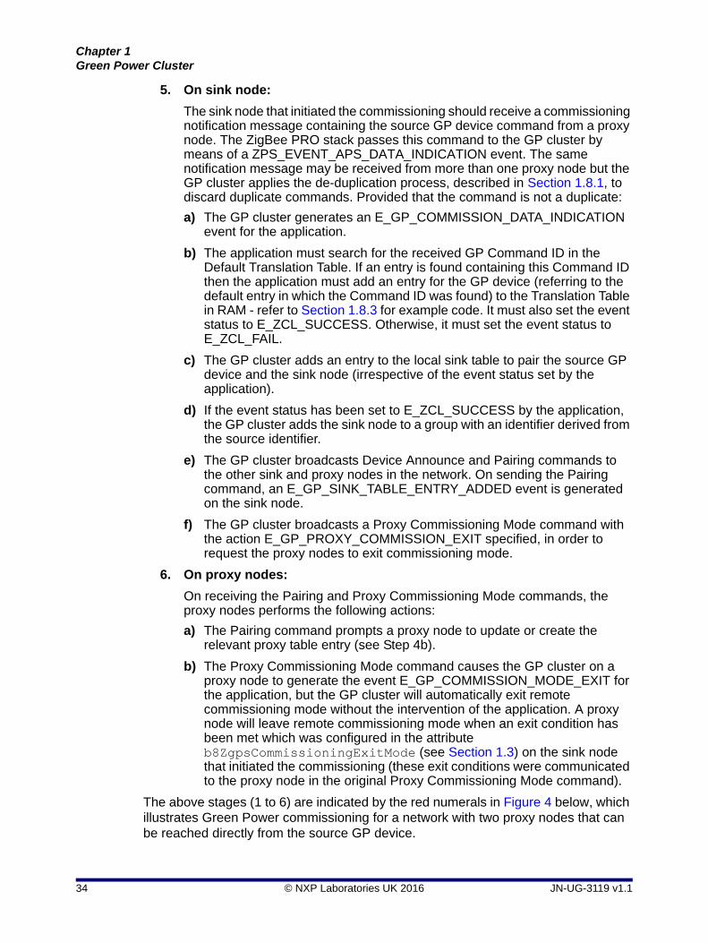
5. On sink node:
The sink node that initiated the commissioning should receive a commissioning notification message containing the source GP device command from a proxy node. The ZigBee PRO stack passes this command to the GP cluster by means of a ZPS_EVENT_APS_DATA_INDICATION event. The same notification message may be received from more than one proxy node but the GP cluster applies the de-duplication process, described in Section 1.8.1, to discard duplicate commands. Provided that the command is not a duplicate:
a) The GP cluster generates an E_GP_COMMISSION_DATA_INDICATION event for the application.
b) The application must search for the received GP Command ID in the Default Translation Table. If an entry is found containing this Command ID then the application must add an entry for the GP device (referring to the default entry in which the Command ID was found) to the Translation Table in RAM - refer to Section 1.8.3 for example code. It must also set the event status to E_ZCL_SUCCESS. Otherwise, it must set the event status to E_ZCL_FAIL.
c) The GP cluster adds an entry to the local sink table to pair the source GP device and the sink node (irrespective of the event status set by the application).
d) If the event status has been set to E_ZCL_SUCCESS by the application, the GP cluster adds the sink node to a group with an identifier derived from the source identifier.
e) The GP cluster broadcasts Device Announce and Pairing commands to the other sink and proxy nodes in the network. On sending the Pairing command, an E_GP_SINK_TABLE_ENTRY_ADDED event is generated on the sink node.
f) The GP cluster broadcasts a Proxy Commissioning Mode command with the action E_GP_PROXY_COMMISSION_EXIT specified, in order to request the proxy nodes to exit commissioning mode.
6. On proxy nodes:
On receiving the Pairing and Proxy Commissioning Mode commands, the proxy nodes performs the following actions:
a) The Pairing command prompts a proxy node to update or create the relevant proxy table entry (see Step 4b).
b) The Proxy Commissioning Mode command causes the GP cluster on a proxy node to generate the event E_GP_COMMISSION_MODE_EXIT for the application, but the GP cluster will automatically exit remote commissioning mode without the intervention of the application. A proxy node will leave remote commissioning mode when an exit condition has been met which was configured in the attribute b8ZgpsCommissioningExitMode (see Section 1.3) on the sink node that initiated the commissioning (these exit conditions were communicated to the proxy node in the original Proxy Commissioning Mode command).
The above stages (1 to 6) are indicated by the red numerals in Figure 4 below, which illustrates Green Power commissioning for a network with two proxy nodes that can be reached directly from the source GP device.
34 © NXP Laboratories UK 2016 JN-UG-3119 v1.1

ZigBee Green Power (for ZigBee 3.0)User Guide
Figure 4: Example of Green Power Auto-Commissioning Mode
Source Node
Sink Node
Proxy Node
Proxy Node
Self-commissioning
Proxy Commissioning Mode (Enter)
GP Command (Auto-commission)
Commissioning Notification
Device Announce
ZigBee PRO Network
1
2
3
4
5
6
Pairing
Proxy Commissioning Mode (Exit)
JN-UG-3119 v1.1 © NXP Laboratories UK 2016 35

Chapter 1Green Power Cluster
1.6.2 GP Device in Uni-directional Commissioning Mode
When in uni-directional commissioning mode, the source GP device is only able to transmit (and not receive). Commissioning of the node into a ZigBee network is requested by the GP device transmitting a GP Commissioning command. The channel number used by the GP device must match the channel number used by the ZigBee network (the method used to determine this channel is not prescribed by ZigBee and is application-specific).
The commissioning process for this case is detailed below and is illustrated in Figure 6. The first two steps of the process are identical to Steps 1 and 2 in Section 1.6.1.
1. On sink node: As described in Step 1 in Section 1.6.1.
2. On proxy nodes: As described in Step 2 in Section 1.6.1.
3. On source GP device:
The source GP device must transmit a GP Commissioning command (E_GP_COMMISSIONING) - this will result from a user action, such as flipping a switch on the node. In the case of an ‘energy harvesting’ GP device (and depending on the application), this command may be repeatedly transmitted for as long as the node has energy.
4. On proxy nodes:
The proxy nodes within radio range of the source GP device receive the GP Commissioning command. On each of these proxy nodes, the GP stub passes the received command in a ZPS_EVENT_APS_ZGP_DATA_INDICATION event up to the GP cluster. First the cluster determines whether it has already received and processed the command (from a previous GP device or proxy node transmission) - this ‘de-duplication’ stage is described in Section 1.8.1. Provided that the command is not a duplicate:
a) If the local node is also a sink (a combo node), the GP cluster checks the local sink table to determine whether there is an entry for the GP device that originated the command. If this is the case, it updates the entry, otherwise it creates a new entry (if a free entry exists).
b) If the local node is a proxy only (a proxy node), the GP cluster checks the local proxy table to determine whether there is an entry for the GP device that originated the command. If this is the case, it will update the entry, otherwise it will create a new entry (if a free entry exists). This update/creation is done once a Pairing command has been received from the sink node (see Step 6a).
Note 1: The commissioning process detailed in this section assumes that the sink node is out-of-range of the source GP device and therefore a proxy node is required to relay messages.
Note 2: For a GP device that employs the MicroMAC stack layer, commands are issued using the MicroMAC API, which is described in Chapter 3.
36 © NXP Laboratories UK 2016 JN-UG-3119 v1.1

ZigBee Green Power (for ZigBee 3.0)User Guide
c) The cluster initiates a broadcast of a ‘commissioning notification’ message in order to forward the command to other GP-enabled nodes in the network.
5. On sink node:
The sink node that initiated the commissioning should receive a commissioning notification message containing the source GP device command from a proxy node. The ZigBee PRO stack passes this command to the GP cluster by means of a ZPS_EVENT_APS_DATA_INDICATION event. The same notification message may be received from more than one proxy node but the GP cluster applies the de-duplication process, described in Section 1.8.1, to discard duplicate commands. Provided that the command is not a duplicate:
a) The GP cluster generates an E_GP_COMMISSION_DATA_INDICATION event for the application.
b) The application must search for the received GP Device ID (identifying the source GP device type) in the Default Translation Table. If an entry is found containing this Device ID then the application must add an entry for the GP device (referring to the default entry in which the Device ID was found) to the Translation Table in RAM - refer to Section 1.8.3 for example code. It must also set the event status to E_ZCL_SUCCESS. Otherwise, it must set the event status to E_ZCL_FAIL.
c) The GP cluster adds an entry to the local sink table to pair the source GP device and the sink node (irrespective of the event status set by the application).
d) If the event status has been set to E_ZCL_SUCCESS by the application, the GP cluster adds the sink node to a group (by calling the ZigBee PRO Stack function ZPS_eAplZdoGroupEndpointAdd()) with a group ID derived from the GP source address of the GP device or a pre-commissioned group ID.
e) The GP cluster broadcasts Device Announce and Pairing commands to the other sink and proxy nodes in the network. On sending the Pairing command, an E_GP_SINK_TABLE_ENTRY_ADDED event is generated on the sink node.
f) The GP cluster broadcasts a Proxy Commissioning Mode command with the action E_GP_PROXY_COMMISSION_EXIT specified, in order to request the proxy nodes to exit commissioning mode.
g) The sink node switches to operational mode according to the ‘exit mode’ condition which has been configured in the attribute b8ZgpsCommissioningExitMode (see Section 1.3). This causes the GP cluster on a sink node to generate the event E_GP_COMMISSION_MODE_EXIT for the application.
JN-UG-3119 v1.1 © NXP Laboratories UK 2016 37

Chapter 1Green Power Cluster
6. On proxy nodes:
On receiving the Pairing and Proxy Commissioning Mode commands, the proxy nodes performs the following actions:
a) The Pairing command prompts a proxy node to update or create the relevant proxy table entry (see Step 4b).
b) The Proxy Commissioning Mode command causes the GP cluster on a proxy node to generate the event E_GP_COMMISSION_MODE_EXIT for the application, but the GP cluster will automatically exit remote commissioning mode without the intervention of the application. A proxy node will leave remote commissioning mode when an exit condition has been met which was configured in the attribute b8ZgpsCommissioningExitMode (see Section 1.3) on the sink node that initiated the commissioning (these exit conditions were communicated to the proxy node in the original Proxy Commissioning Mode command).
The above stages (1 to 6) are indicated by the red numerals in Figure 6 below, which illustrates Green Power commissioning for a network with two proxy nodes that can be reached directly from the source GP device.
Figure 5: Example of Green Power Uni-directional Commissioning Mode
Source Node
Self-commissioning
Proxy Commissioning Mode (Enter)
GP Commissioning
Commissioning Notification
ZigBee PRO Network
1
2
3
4
5
6
Device Announce
Pairing
Proxy Commissioning Mode (Exit)
Sink Node
Proxy Node
Proxy Node
38 © NXP Laboratories UK 2016 JN-UG-3119 v1.1
ZigBee Green Power (for ZigBee 3.0)User Guide
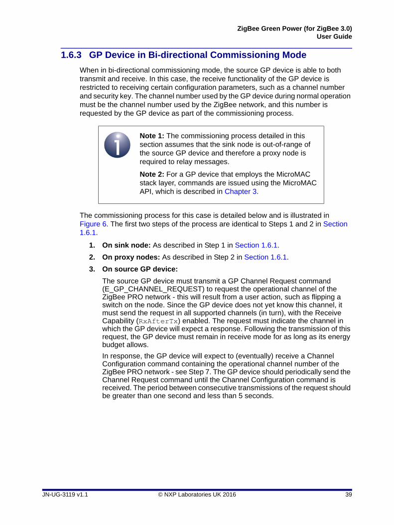
1.6.3 GP Device in Bi-directional Commissioning Mode
When in bi-directional commissioning mode, the source GP device is able to both transmit and receive. In this case, the receive functionality of the GP device is restricted to receiving certain configuration parameters, such as a channel number and security key. The channel number used by the GP device during normal operation must be the channel number used by the ZigBee network, and this number is requested by the GP device as part of the commissioning process.
The commissioning process for this case is detailed below and is illustrated in Figure 6. The first two steps of the process are identical to Steps 1 and 2 in Section 1.6.1.
1. On sink node: As described in Step 1 in Section 1.6.1.
2. On proxy nodes: As described in Step 2 in Section 1.6.1.
3. On source GP device:
The source GP device must transmit a GP Channel Request command (E_GP_CHANNEL_REQUEST) to request the operational channel of the ZigBee PRO network - this will result from a user action, such as flipping a switch on the node. Since the GP device does not yet know this channel, it must send the request in all supported channels (in turn), with the Receive Capability (RxAfterTx) enabled. The request must indicate the channel in which the GP device will expect a response. Following the transmission of this request, the GP device must remain in receive mode for as long as its energy budget allows.
In response, the GP device will expect to (eventually) receive a Channel Configuration command containing the operational channel number of the ZigBee PRO network - see Step 7. The GP device should periodically send the Channel Request command until the Channel Configuration command is received. The period between consecutive transmissions of the request should be greater than one second and less than 5 seconds.
Note 1: The commissioning process detailed in this section assumes that the sink node is out-of-range of the source GP device and therefore a proxy node is required to relay messages.
Note 2: For a GP device that employs the MicroMAC stack layer, commands are issued using the MicroMAC API, which is described in Chapter 3.
JN-UG-3119 v1.1 © NXP Laboratories UK 2016 39

Chapter 1Green Power Cluster
4. On proxy nodes:
The proxy nodes within radio range of the source GP device receive a transmitted Channel Request command in the operational channel. On each of these proxy nodes, the GP stub passes the received command in a ZPS_EVENT_APS_ZGP_DATA_INDICATION event up to the GP cluster.
a) The GP cluster will check whether the proxy table is full. If there is no free proxy table entry then it will discard the channel request (and not respond). If there is a free proxy table entry then the GP cluster will generate an E_GP_RECEIVED_CHANNEL_REQUEST event for the application.
b) The application must now decide whether it is able to respond to the request, which will require it to temporarily switch (for 5 seconds) from the operational channel of the network to the response channel specified in the request. The application must set the value of bIsActAsTempMaster to TRUE if it is able to switch channel or FALSE if it must remain on the operational channel. If the application returns FALSE, the cluster will not process the Channel Request and will not broadcast a Commissioning Notification command (see below).
c) The GP cluster will broadcast a Commissioning Notification message into the network (in the operational channel). The message uses the proxy node's own source address and sequence number.
5. On sink node:
The sink node that initiated the commissioning should receive a Commissioning Notification message containing the source GP device command from a proxy node. The ZigBee PRO stack passes this command to the GP cluster by means of a ZPS_EVENT_APS_DATA_INDICATION event. The same notification message may be received from more than one proxy node but the GP cluster applies the de-duplication process, described in Section 1.8.1, to discard duplicate commands.
Provided that the command is not a duplicate, the sink node prepares a response containing a GP Channel Configuration command in its payload. This command contains the operational channel number of the network. The sink node elects the relevant proxy node to act as the ‘temporary master’ for communication with the GP device and includes the 16-bit network address of this proxy node in the response payload. This response is then broadcast within the network.
6. On proxy nodes:
On receipt of the response containing the GP Channel Configuration command from the sink node, a proxy node checks whether its network address matches the address of the ‘temporary master’ specified in the command.
If there is no match, the proxy node discards the command and removes any previous pending commands for this GP device from its GP transmit queue.
If there is a match, the proxy node adds the Channel Configuration command (in a GP frame) to its GP transmit queue for transmission to the GP device. It then switches to the response channel (specified by the GP device), with a 5-second timeout, and enters receive mode.
In receive mode, the proxy node first waits for another Channel Request from the GP device. This is necessary to ensure that the GP device is in receive
40 © NXP Laboratories UK 2016 JN-UG-3119 v1.1
ZigBee Green Power (for ZigBee 3.0)User Guide
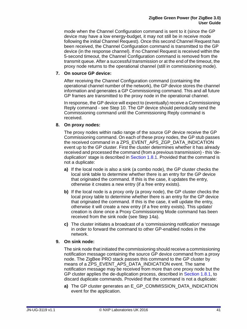
mode when the Channel Configuration command is sent to it (since the GP device may have a low energy-budget, it may not still be in receive mode following the initial Channel Request). Once this second Channel Request has been received, the Channel Configuration command is transmitted to the GP device (in the response channel). If no Channel Request is received within the 5-second timeout, the Channel Configuration command is removed from the transmit queue. After a successful transmission or at the end of the timeout, the proxy node returns to the operational channel (still in commissioning mode).
7. On source GP device:
After receiving the Channel Configuration command (containing the operational channel number of the network), the GP device stores the channel information and generates a GP Commissioning command. This and all future GP frames are transmitted to the proxy node in the operational channel.
In response, the GP device will expect to (eventually) receive a Commissioning Reply command - see Step 10. The GP device should periodically send the Commissioning command until the Commissioning Reply command is received.
8. On proxy nodes:
The proxy nodes within radio range of the source GP device receive the GP Commissioning command. On each of these proxy nodes, the GP stub passes the received command in a ZPS_EVENT_APS_ZGP_DATA_INDICATION event up to the GP cluster. First the cluster determines whether it has already received and processed the command (from a previous transmission) - this ‘de-duplication’ stage is described in Section 1.8.1. Provided that the command is not a duplicate:
a) If the local node is also a sink (a combo node), the GP cluster checks the local sink table to determine whether there is an entry for the GP device that originated the command. If this is the case, it updates the entry, otherwise it creates a new entry (if a free entry exists).
b) If the local node is a proxy only (a proxy node), the GP cluster checks the local proxy table to determine whether there is an entry for the GP device that originated the command. If this is the case, it will update the entry, otherwise it will create a new entry (if a free entry exists). This update/creation is done once a Proxy Commissioning Mode command has been received from the sink node (see Step 14a).
c) The cluster initiates a broadcast of a ‘commissioning notification’ message in order to forward the command to other GP-enabled nodes in the network.
9. On sink node:
The sink node that initiated the commissioning should receive a commissioning notification message containing the source GP device command from a proxy node. The ZigBee PRO stack passes this command to the GP cluster by means of a ZPS_EVENT_APS_DATA_INDICATION event. The same notification message may be received from more than one proxy node but the GP cluster applies the de-duplication process, described in Section 1.8.1, to discard duplicate commands. Provided that the command is not a duplicate:
a) The GP cluster generates an E_GP_COMMISSION_DATA_INDICATION event for the application.
JN-UG-3119 v1.1 © NXP Laboratories UK 2016 41

Chapter 1Green Power Cluster
b) The application must search for the received GP Device ID (identifying the GP source device type) in the Default Translation Table. If entries are found containing this Device ID then the application must add corresponding entries for the GP device (referring to the Default Translation Table entries in which the Device ID was found) to the Translation Table in RAM (refer to Section 1.8.3 for example code), and set the event status to E_ZCL_SUCCESS. Otherwise, it must set the event status to E_ZCL_FAIL.
c) If the event status has been set to E_ZCL_SUCCESS by the application, the GP cluster generates a response command with a GP Commissioning Reply in the payload, otherwise the commissioning notification is dropped. The sink node elects the relevant proxy node to act as the ‘temporary master’ for communication with the GP device and includes the 16-bit network address of this proxy node in the response payload. This response is then broadcast within the network.
10. On proxy nodes:
On receipt of the response containing the GP Commissioning Reply command from the sink node, a proxy node checks whether its network address matches the address of the ‘temporary master’ specified in the command.
If there is no match, the proxy node discards the command and removes any previous pending commands for this GP device from its GP transmit queue.
If there is a match, the proxy node adds the Commissioning Reply command (in a GP frame) to its GP transmit queue for transmission to the GP device and enters receive mode.
In receive mode, the proxy node first waits for another GP Commissioning command transmitted from the source GP device in the operational channel. This is necessary to ensure that the GP device is in receive mode when the GP Commissioning Reply command is sent to it (since the GP device may have a low energy-budget, it may not still be in receive mode following the initial Commissioning command). Once this second Commissioning command has been received, the Commissioning Reply command is transmitted to the GP device (in the operational channel).
11. On source GP device:
After receiving the Commissioning Reply command, the GP device checks whether the GP source address or IEEE address within the command matches its own and, if this is the case, stores the supplied commissioning parameters (e.g. channel, PANID, key) in non-volatile memory. It then transmits a GP Success command.
12. On proxy nodes:
The proxy nodes within radio range of the source GP device receive the GP Success command. The GP cluster initiates a broadcast of a 'commissioning notification' message in order to forward the command to other GP-enabled nodes in the network.
On those proxy nodes that are also sinks, on receiving the GP Success command an E_GP_SINK_TABLE_ENTRY_ADDED event is generated for the application to indicate that a local sink table entry has been created or modified (see Step 8a).
42 © NXP Laboratories UK 2016 JN-UG-3119 v1.1

ZigBee Green Power (for ZigBee 3.0)User Guide
13. On sink node:
The sink node that initiated the commissioning should receive a commissioning notification message containing the source GP device command from a proxy node. The ZigBee PRO stack passes this command to the GP cluster by means of a ZPS_EVENT_APS_DATA_INDICATION event. The same notification message may be received from more than one proxy node but the GP cluster applies the de-duplication process, described in Section 1.8.1, to discard duplicate commands. Provided that the command is not a duplicate:
a) The GP cluster generates an E_GP_SUCCESS_CMD_RCVD event for the application.
b) The GP cluster adds the sink node to a group (by calling the ZigBee PRO Stack function ZPS_eAplZdoGroupEndpointAdd()) with a group ID derived from the GP source address of the GP device or a pre-commissioned group ID. An E_GP_SINK_TABLE_ENTRY_ADDED event is generated to notify the application of this addition.
c) The GP cluster broadcasts Device Announce and Pairing commands to the other sink and proxy nodes in the network.
d) The GP cluster broadcasts a Proxy Commissioning Mode command with the action E_GP_PROXY_COMMISSION_EXIT specified, in order to request the proxy nodes to exit commissioning mode.
e) The sink node switches to operational mode according to the ‘exit mode’ condition which has been configured in the attribute b8ZgpsCommissioningExitMode (see Section 1.3). This causes the GP cluster on a sink node to generate the event E_GP_COMMISSION_MODE_EXIT for the application.
14. On proxy nodes:
On receiving the Proxy Commissioning Mode commands, the proxy nodes performs the following actions:
a) The Proxy Commissioning Mode command prompts a proxy node to update or create the relevant proxy table entry (see Step 8b).
b) The Proxy Commissioning Mode command causes the GP cluster on a proxy node to generate the event E_GP_COMMISSION_MODE_EXIT for the application, but the GP cluster will automatically exit remote commissioning mode without the intervention of the application. A proxy node will leave remote commissioning mode when an exit condition has been met which was configured in the attribute b8ZgpsCommissioningExitMode (see Section 1.3) on the sink node that initiated the commissioning (these exit conditions were communicated to the proxy node in the original Proxy Commissioning Mode command).
The above stages (1 to 14) are indicated by the red numerals in Figure 6 below, which illustrates Green Power commissioning for a network with two proxy nodes that can be reached directly from the source GP device.
JN-UG-3119 v1.1 © NXP Laboratories UK 2016 43

Chapter 1Green Power Cluster
Figure 6: Example of Green Power Bi-directional Commissioning Mode
Source Node
Sink Node
Proxy Node
Proxy Node
Self-commissioning
Proxy Commissioning Mode (Enter)
GP Channel Requests (in all supported channels)
Commissioning Notification
GP Channel Configuration (tunnelled in response)
ZigBee PRO Network
1
2
3
4
5
6
GP Channel Requests (in all supported channels)
GP Channel Configuration (in specified response channel)
GP Commissioning (in operational channel)
Commissioning Notification
GP Commissioning Reply (tunnelled in response)
GP Commissioning (in operational channel)
GP Commissioning Reply (in operational channel)
GP Success (in operational channel)
Commissioning Notification
Device Announce
Pairing
Proxy Commissioning Mode (Exit)
7
89
10
11
12
13
14
44 © NXP Laboratories UK 2016 JN-UG-3119 v1.1

ZigBee Green Power (for ZigBee 3.0)User Guide
1.6.4 Decommissioning
This section describes how a GP device can be decommissioned from operating with a ZigBee PRO network. A GP device can be decommissioned while in commissioning mode (see Steps 1 and 2 in Section 1.6.1) or, provided packets are secured, in operational mode.
1. On source GP device:
The GP device must transmit a Decommissioning command (E_GP_DECOMMISSIONING) - this will result from a user action, such as flipping a switch on the node. In the case of an ‘energy harvesting’ GP device (and depending on the application), this command may be repeatedly transmitted for as long as the node has energy.
2. On proxy nodes:
The proxy nodes within radio range of the source GP device receive the transmitted command. On each of these proxy nodes, the GP stub passes the received command in a ZPS_EVENT_APS_ZGP_DATA_INDICATION event up to the GP cluster. First the cluster determines whether it has already received and processed the command (from a previous GP device or proxy node transmission) - this ‘de-duplication’ stage is described in Section 1.8.1. Provided that the command is not a duplicate, the cluster initiates a broadcast of a ‘GP notification’ message (if in operational mode) or a ‘GP commissioning notification’ message (if in commissioning mode), in order to forward the command to other GP-enabled nodes in the network.
3. On sink node:
The sink node that initiated the commissioning should receive a commissioning notification message containing the source GP device command from a proxy node. The ZigBee PRO stack passes this command to the GP cluster by means of a ZPS_EVENT_APS_DATA_INDICATION event. The same notification message may be received from more than one proxy node but the GP cluster applies the de-duplication process, described in Section 1.8.1, to discard duplicate commands. Provided that the command is not a duplicate:
a) The GP cluster first searches for a sink table entry for the GP device. If none is found, the command is discarded (and the steps below are omitted).
b) The GP cluster then checks that the security level and key type specified in the received command match those contained in the sink table entry.
c) If the security checks are satisfied, the GP cluster removes the sink table entry. If the GP device has an associated group address, this is also deleted from the local group address table.
d) If the security checks are satisfied, the GP cluster also generates an E_GP_DECOMM_CMD_RCVD event for the application.
e) The application must now delete the Translation Table entries (in RAM) for the GP device.
f) If the removed sink table entry included a group address, the GP cluster broadcasts a ‘pairing configuration’ command with the ‘RemoveGPD’ bit set. The transmitted command instructs the receiving nodes that are in the relevant group to remove the GP device from their sink tables.
JN-UG-3119 v1.1 © NXP Laboratories UK 2016 45

Chapter 1Green Power Cluster
g) If the decommissioning was performed in commissioning mode, the sink node switches to operational mode according to the ‘exit mode’ condition configured in the attribute b8ZgpsCommissioningExitMode (see Section 1.3). This causes the GP cluster on a sink node to generate the event E_GP_COMMISSION_MODE_EXIT for the application.
1.7 Operation
Once nodes have been commissioned for Green Power (as described in Section 1.6), they will operate as outlined below (and illustrated in Figure 7):
1. On source GP device:
The source GP device sends a command in a Green Power frame to the network (as the result of a user action, such as pressing a button on the node).
2. On proxy nodes:
The proxy nodes within radio range receive the GP frame, which is passed to the GP cluster in a ZCL event.
If the local node is also a sink (as well as a proxy), the GP frame will be processed as described for a sink node in Step 5.
3. On proxy nodes:
The GP command is ‘tunnelled’ in a ZigBee frame and groupcast within the network.
4. On proxy nodes:
The proxy nodes receive the forwarded GP command from each other, recognise it as a duplicate (see Section 1.8.1) and discard it.
Note: The GP frame has exactly the same format as it had in commissioning mode (with the ‘auto-commissioning’ bit set), but the proxy node is now in operational mode and so treats the frame as an operational command.
Note: All proxy nodes forward the GP command in identical ZigBee frames with the same source address and APS sequence number, both derived from the GP frame. This allows ZigBee to identify duplicate broadcasts and reduce flooding within the network.
46 © NXP Laboratories UK 2016 JN-UG-3119 v1.1

ZigBee Green Power (for ZigBee 3.0)User Guide
5. On sink node(s):
A target sink node receives the tunnelled GP command from the proxy nodes (all except one command will be identified as duplicates and discarded - see Section 1.8.1). The GP cluster checks the local sink and translation tables to determine whether the command is for the local node. If it finds relevant entries in both tables, it generates an E_GP_ZGPD_COMMAND_RCVD event for the application and translates the GP command. It then directs the command to the relevant cluster command handler. The application then takes the appropriate action (such as switching on a lamp).
The above stages (1 to 5) are indicated by the red numerals in Figure 7 below, which illustrates Green Power operation for a network with two proxy nodes that can be reached directly from the source GP device.
Note: If the sink node receives the GP command directly from the source GP device (without being tunnelled) and it is also a proxy node, it must tunnel the command into the network in case other sink nodes also require the command.
Figure 7: Example of Green Power Operation
Source Node
Sink Node
Proxy Node
Proxy Node
Tunnelled Command
GP Command
ZigBee PRO Network
1 2
34
5
JN-UG-3119 v1.1 © NXP Laboratories UK 2016 47

Chapter 1Green Power Cluster
1.8 Useful Commissioning and Operational Topics
This section describes the following topics which are referenced elsewhere in the chapter:
De-duplication - see Section 1.8.1
Pairing a source GP device with multiple sink nodes - see Section 1.8.2
Creating a translation table - see Section 1.8.3
Persistent data management - see Section 1.8.4
1.8.1 De-duplication
A proxy or sink node can receive the same GP command multiple times due to consecutive re-transmissions by the source GP device and/or tunnelled re-broadcasts by proxy nodes. Duplicate commands must be identified and discarded.
The Green Power cluster therefore implements a de-duplication process on received GP commands. These commands can be received by the GP cluster via two stack routes (refer to Figure 2):
via the GP stub, for a GP command received directly from the GP device
via the ZigBee PRO stack layers, for a tunnelled command in a ZigBee frame
The cluster maintains a ‘duplicate table’, containing an entry for each GP command received, irrespective of its route. A command is identified by means of its source address and an 8-bit random sequence number generated by the GP device. Since the probability of a new command having the same sequence number as an earlier command (from the same GP device) is not insignificant, the CRC value of a GP command frame is also stored to help identify the command. Thus, when a command is received, the cluster compares all the above identifiers with those of the commands in the duplicate table:
If the new command is a duplicate of a command in the table, it is discarded
If the new command is not a duplicate, it is added to the table
Since it is possible that the GP device will eventually generate a valid new command with identical identifiers to an earlier command, an ‘ageing time’ or timeout is applied to the entries of the duplicate table - by default, this is 2 seconds. After remaining in the table for this time, a command is automatically removed from the table.
The duplicate table size is 5, by default. However, the default values for the table size and ageing time can be over-ridden in the file zcl_options.h (see Section 1.14).
48 © NXP Laboratories UK 2016 JN-UG-3119 v1.1

ZigBee Green Power (for ZigBee 3.0)User Guide
1.8.2 Pairing a GP Device with Multiple Sink Nodes
A source GP device can be paired with multiple sink nodes - for example, a single switch that controls a set of five lamps. Some of the sink nodes could also act as proxy nodes.
All of the sink nodes can be paired with the GP device in a single commissioning session (described in Section 1.6), as follows:
1. One of the sink nodes must initiate the commissioning session using the function eGP_ProxyCommissioningMode(). This will put all of the other sink/proxy nodes into remote commissioning mode.
2. The relevant sink nodes must then be put into pairing mode. This should be done on the sink nodes (except the initial sink node) by calling the function eGP_ProxyCommissioningMode() as the result of a user action - if this function is called while the host node is in remote commissioning mode then the node will enter pairing mode (and no Proxy Commissioning Mode command will be broadcast).
3. The GP device must then transmit a command initiated by a user action. This will result in commissioning notifications propagating through the network.
4. Once a commissioning notification (containing the GP device command) has been received by a sink node, this node will update its translation and sink tables to establish a pairing with the GP device.
1.8.3 Creating a Translation Table
A sink node must have a translation table, which is used to translate GP commands from the source GP device into standard ZigBee commands on the sink node. The table contains a translation for every possible command from each GP device with which the sink node is paired. Translation Tables are fully introduced in Section 1.4.1.1.
A translation table is established in RAM on a sink node during the commissioning phase of the node and its entries refer to a pre-defined ‘Default Translation Table’, which is stored by the application (for example, in Flash memory).
Note: Pairing a source GP device with multiple sink nodes is not possible when the GP device is operating in bi-directional commissioning mode (but is possible in auto-commissioning and uni-directional commissioning modes).
JN-UG-3119 v1.1 © NXP Laboratories UK 2016 49

Chapter 1Green Power Cluster
1.8.3.1 Defining a Translation Table in RAM
The application on the sink node must define a Translation Table in RAM as the following array:
tsGP_TranslationTableEntry asTranslationTable[GP_NUMBER_OF_TRANSLATION_TABLE_ENTRIES];
where each array element is a tsGP_TranslationTableEntry structure for one GP device with which the local sink node will be paired (this structure is described in Section 1.12.11):
struct tsGP_TranslationTableEntry
{
zbmap8 b8Options;
tuGP_ZgpdDeviceAddr uZgpdDeviceAddr;
uint8 u8NoOfCmdInfo;
tsGP_GpToZclCommandInfo *psGpToZclCmdInfo;
};
Once populated (see below), this structure contains the address of the GP device and points to the ‘Default Translation Table’ entries for the relevant GP device type (identified by its Device ID) and GP commands.
The above array declaration reserves RAM space for the Translation Table and the array will be populated by the application during the commissioning process. The value of GP_NUMBER_OF_TRANSLATION_TABLE_ENTRIES is defined in the compile-time options (see Section 1.14).
A pointer (memory address) to the above (empty) Translation Table must be provided in the endpoint registration function eGP_RegisterComboBasicEndPoint() during initialisation (see Section 1.5).
1.8.3.2 Defining a Default Translation Table
As described in Section 1.4.1.1, the entries of the above Translation Table in RAM refer to the ‘Default Translation Table’ entries that are pre-defined as constants and held in Flash memory. In the Default Translation Table, each entry contains a single command translation for a GP source device type (identified by its Device ID). The table contains entries for all the commands supported by all the device types with which the local sink node could potentially be paired.
The Default Translation Table must be defined as a const in the application. Example Default Translation Table entries are provided below.
const tsGP_GpToZclCommandInfo asGpToZclCmdInfo[] = {
#ifdef GP_ON_OFF_SWITCH
{0x02, 0x20, 0x00, 0x01, 0x0006, 0x00, {0}}, /* On/Off Switch, GP Off Cmd Id, ZB Cmd Id, EP, Cluster ID, ZB Payload Length, NULL data */
{0x02, 0x21, 0x01, 0x01, 0x0006, 0x00, {0}}, /* On/Off Switch, GP On Cmd Id, ZB Cmd Id, EP, Cluster ID, ZB Payload Length, NULL data */
50 © NXP Laboratories UK 2016 JN-UG-3119 v1.1

ZigBee Green Power (for ZigBee 3.0)User Guide
{0x02, 0x22, 0x02, 0x01, 0x0006, 0x00, {0}}, /* On/Off Switch, GP Toggle Cmd Id, ZB Cmd Id, EP, Cluster ID, ZB Payload Length, NULL data */
#endif
#ifdef GP_LEVEL_CONTROL_SWITCH
{0x03, 0x35, 0x05, 0x01, 0x0008, 0x02, {0x00, 0x64}}, /* On/Off L Switch, GP Move Up with On/Off Cmd Id, ZB Cmd Id, EP, Cluster ID, ZB Payload Length, NULL data */
{0x03, 0x36, 0x05, 0x01, 0x0008, 0x02, {0x01, 0x64}}, /* On/Off L Switch, GP Move Down with On/Off Cmd Id, EP, Cluster ID, ZB Payload Length, NULL data */
#endif
};
1.8.3.3 Populating the Translation Table in RAM
During the commissioning process (see Section 1.6), on receiving the event E_GP_COMMISSION_DATA_INDICATION, the application on a sink node must populate the translation table. It must search for the received GP Device ID/Command ID combination in the translation table in RAM. If an entry containing this Device ID/Command ID combination is not found then the application must add an entry (tsGP_TranslationTableEntry) for it to the Translation Table in RAM. This entry contains a pointer (psGpToZclCmdInfo) to a ‘Default Translation Table’ entry (tsGP_GpToZclCommandInfo) for the command. If an entry for this command is not present in the Default Translation Table, the application must add it. Finally, the application must populate the pointer (psGpToZclCmdInfo) in the translation table entry and also update the number of commands mapped for the particular device (u8NoOfCmdInfo).
This is illustrated in the following example code.
tsGP_TranslationTableEntry asGpTranslationTable[GP_NUMBER_OF_TRANSLATION_TABLE_ENTRIES];
tsGP_GpToZclCommandInfo asGpToZclLevelControlCmdInfo[] = {
/* On/Off Switch, GP Off Cmd Id, ZB Cmd Id, EP, Cluster ID, ZB Payload Length, NULL data */
{E_GP_ZGP_LEVEL_CONTROL_SWITCH, E_GP_OFF, 0x00, 1, GP_GENERAL_CLUSTER_ID_ONOFF, 0x00, {0}},
/* On/Off Switch, GP On Cmd Id, ZB Cmd Id, EP, Cluster ID, ZB Payload Length, NULL data */
{E_GP_ZGP_LEVEL_CONTROL_SWITCH, E_GP_ON, 0x01, 1, GP_GENERAL_CLUSTER_ID_ONOFF, 0x00, {0}},
/* On/Off Switch, GP Toggle Cmd Id, ZB Cmd Id, EP, Cluster ID, ZB Payload Length, NULL data */
{E_GP_ZGP_LEVEL_CONTROL_SWITCH, E_GP_TOGGLE, 0x02, 1, GP_GENERAL_CLUSTER_ID_ONOFF, 0x00, {0}},
/* Level control switch , Level control stop, ZB Cmd Id, EP, Cluster ID, ZB Payload Length, NULL data */
{E_GP_ZGP_LEVEL_CONTROL_SWITCH, E_GP_LEVEL_CONTROL_STOP, E_CLD_LEVELCONTROL_CMD_STOP, 1, GP_GENERAL_CLUSTER_ID_LEVEL_CONTROL, 0x00, {0}},
/* Level control switch,Move Up, ZB Cmd Id, EP, Cluster ID, ZB Payload Length, NULL data */
JN-UG-3119 v1.1 © NXP Laboratories UK 2016 51
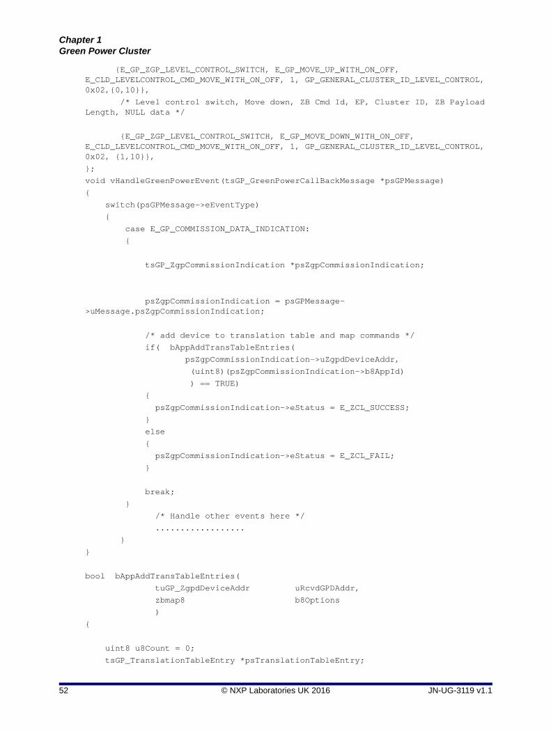
Chapter 1Green Power Cluster
{E_GP_ZGP_LEVEL_CONTROL_SWITCH, E_GP_MOVE_UP_WITH_ON_OFF, E_CLD_LEVELCONTROL_CMD_MOVE_WITH_ON_OFF, 1, GP_GENERAL_CLUSTER_ID_LEVEL_CONTROL, 0x02,{0,10}},
/* Level control switch, Move down, ZB Cmd Id, EP, Cluster ID, ZB Payload Length, NULL data */
{E_GP_ZGP_LEVEL_CONTROL_SWITCH, E_GP_MOVE_DOWN_WITH_ON_OFF, E_CLD_LEVELCONTROL_CMD_MOVE_WITH_ON_OFF, 1, GP_GENERAL_CLUSTER_ID_LEVEL_CONTROL, 0x02, {1,10}},
};
void vHandleGreenPowerEvent(tsGP_GreenPowerCallBackMessage *psGPMessage)
{
switch(psGPMessage->eEventType)
{
case E_GP_COMMISSION_DATA_INDICATION:
{
tsGP_ZgpCommissionIndication *psZgpCommissionIndication;
psZgpCommissionIndication = psGPMessage->uMessage.psZgpCommissionIndication;
/* add device to translation table and map commands */
if( bAppAddTransTableEntries(
psZgpCommissionIndication->uZgpdDeviceAddr,
(uint8)(psZgpCommissionIndication->b8AppId)
) == TRUE)
{
psZgpCommissionIndication->eStatus = E_ZCL_SUCCESS;
}
else
{
psZgpCommissionIndication->eStatus = E_ZCL_FAIL;
}
break;
}
/* Handle other events here */
..................
}
}
bool bAppAddTransTableEntries(
tuGP_ZgpdDeviceAddr uRcvdGPDAddr,
zbmap8 b8Options
)
{
uint8 u8Count = 0;
tsGP_TranslationTableEntry *psTranslationTableEntry;
52 © NXP Laboratories UK 2016 JN-UG-3119 v1.1

ZigBee Green Power (for ZigBee 3.0)User Guide
/* get free translation entry( entry with 0x00(uDummydeviceAddr) as src id )*/
psTranslationTableEntry = psApp_GPGetTranslationTable(0, &uDummydeviceAddr);
/* check pointer */
if(psTranslationTableEntry != NULL)
{
psTranslationTableEntry->b8Options =
b8Options;
psTranslationTableEntry->uZgpdDeviceAddr =
uRcvdGPDAddr;
psTranslationTableEntry->psGpToZclCmdInfo = asGpToZclLevelControlCmdInfo;
psTranslationTableEntry->u8NoOfCmdInfo = sizeof(asGpToZclLevelControlCmdInfo)/sizeof(tsGP_GpToZclCommandInfo);
return TRUE;
}
else
{
return FALSE;
}
}
PRIVATE tsGP_TranslationTableEntry* psApp_GPGetTranslationTable(
uint8 u8AppId,
tuGP_ZgpdDeviceAddr *uSrcAddr)
{
uint8 u8Count;
for(u8Count = 0; u8Count < GP_NUMBER_OF_TRANSLATION_TABLE_ENTRIES; u8Count++)
{
/* if ZGPD Src ID is zero then it is free entry */
if(bGP_CheckGPDAddressMatch(
sGP_PDM_Data.asGpTranslationTable[u8Count].b8Options,
u8AppId,
&sGP_PDM_Data.asGpTranslationTable[u8Count].uZgpdDeviceAddr,
uSrcAddr
))
{
return &(sGP_PDM_Data.asGpTranslationTable[u8Count]);
}
}
return NULL;
}
In the above example code, an entry for only one command is added to the Translation Table in RAM during the event. However, the application can add entries for other relevant commands for the GP device, based on the received Command ID. For
JN-UG-3119 v1.1 © NXP Laboratories UK 2016 53

Chapter 1Green Power Cluster
example, if the received Command ID is 20 (Off Cmd), the application can also set up entries for the related commands corresponding to Command IDs 21 and 22.
1.8.4 Persistent Data Management
The Green Power cluster requires attribute data to be preserved in non-volatile memory (e.g. Flash memory) in order to facilitate a recovery of the attribute data (such as a sink table and security key) following a device reboot. The Persistent Data Manager (PDM) module should be used to perform this data saving and recovery. The PDM module is implemented as described in the JN51xx Core Utilities User Guide (JN-UG-3116).
When the sink/proxy table on the local node has been changed, the Green Power cluster will generate the event E_GP_PERSIST_SINK_PROXY_TABLE, which will contain the data to be saved to non-volatile memory. The application should perform the data storage using the functions of the PDM module.
The following code fragment illustrates the reservation of memory space for persistent attribute data:
typedef struct
{
tsGP_PersistedData sPersistedGpData;
} tsDevice;
PUBLIC tsDevice s_sDevice;
PUBLIC PDM_tsRecordDescriptor s_GPPDDesc;
When a device is restarted, the function vGP_RestorePersistedData() should be called during application initialisation after the endpoint registration function has been called. If persisted data is available on the device, the bSetToDefault parameter in the function should be set to the appropriate bitmap, from the following:
E_GP_DEFAULT_ATTRIBUTE_VALUE to reset the attribute values
E_GP_DEFAULT_PROXY_SINK_TABLE_VALUE to reset the sink/proxy table entries
If no persisted data is available, the bSetToDefault parameter should be set to zero in order to reset the Green Power cluster attributes to their default values.
Note: A sink node may be paired with two or more source GP devices of the same GP device type (with the same Device ID). In this case, in the Translation Table in RAM, there will be separate entries for these GP devices (distinguished by their addresses), even though these entries are based on common ‘Default Translation Table’ entries for their device type.
54 © NXP Laboratories UK 2016 JN-UG-3119 v1.1

ZigBee Green Power (for ZigBee 3.0)User Guide
1.9 Green Power Events
The Green Power cluster has its own events that are handled through the callback mechanism described in the ZCL User Guide (JN-UG-3115). If a device uses the Green Power cluster then GP event handling must be included in the callback function for the GP endpoint, where this callback function is registered through the function eGP_RegisterComboBasicMinimumEndPoint() or eGP_RegisterProxyBasicEndPoint(). The registered callback function will then be invoked whenever a GP event occurs.
For a Green Power event, the eEventType field of the tsZCL_CallBackEvent structure is set to E_ZCL_CBET_CLUSTER_CUSTOM. This event structure also contains an element sClusterCustomMessage, which is itself a structure containing a field pvCustomData. This field is a pointer to the following tsGP_GreenPowerCallBackMessage structure:
typedef struct
{
teGP_GreenPowerCallBackEventType eEventType;
union
{
tsGP_ZgpsProxySinkTable *psZgpsProxySinkTable;
tsGP_ZgpCommissionIndication *psZgpCommissionIndication;
ZPS_teStatus eAddGroupTableStatus;
ZPS_teStatus eRemoveGroupTableStatus;
bool_t bIsActAsTempMaster;
tsGP_ZgpTransTableResponseCmdPayload *psZgpTransRspCmdPayload;
tsGP_ZgpsTranslationTableUpdate *psTransationTableUpdate;
tsGP_ZgpsPairingConfigCmdRcvd *psPairingConfigCmdRcvd;
tsGP_PersistedData *psPersistedData;
tsGP_ZgpDecommissionIndication *psZgpDecommissionIndication;
}uMessage;
tsGP_ProxyTableRespCmdPayload *psZgpProxyTableRespCmdPayload;
tsGP_ZgpResponseCmdPayload *psZgpResponseCmdPayload;
tsGP_ZgpNotificationCmdPayload *psZgpNotificationCmdPayload;
tsGP_ZgpCommissioningNotificationCmdPayload *psZgpCommissioningNotificationCmdPayload;
tsGP_ZgpPairingCmdPayload *psZgpPairingCmdPayload;
tsGP_ZgpPairingConfigCmdPayload *psZgpPairingConfigCmdPayload;
}tsGP_GreenPowerCallBackMessage;
JN-UG-3119 v1.1 © NXP Laboratories UK 2016 55

Chapter 1Green Power Cluster
The eEventType field of the above structure specifies the type of GP event that has been generated - these event types are enumerated in the following teGP_GreenPowerCallBackEventType structure:
typedef enum PACK{ E_GP_COMMISSION_DATA_INDICATION = 0x00, E_GP_COMMISSION_MODE_ENTER, E_GP_COMMISSION_MODE_EXIT, E_GP_CMD_UNSUPPORTED_PAYLOAD_LENGTH, E_GP_SINK_PROXY_TABLE_ENTRY_ADDED, E_GP_SINK_PROXY_TABLE_FULL, E_GP_ZGPD_COMMAND_RCVD,
E_GP_ZGPD_CMD_RCVD_WO_TRANS_ENTRY,
E_GP_ADDING_GROUP_TABLE_FAIL, E_GP_RECEIVED_CHANNEL_REQUEST, E_GP_TRANSLATION_TABLE_RESPONSE_RCVD, E_GP_TRANSLATION_TABLE_UPDATE, E_GP_SECURITY_LEVEL_MISMATCH, E_GP_SECURITY_PROCESSING_FAILED, E_GP_REMOVING_GROUP_TABLE_FAIL, E_GP_PAIRING_CONFIGURATION_CMD_RCVD, E_GP_PERSIST_SINK_PROXY_TABLE, E_GP_SUCCESS_CMD_RCVD, E_GP_DECOMM_CMD_RCVD, E_GP_SHARED_SECURITY_KEY_TYPE_IS_NOT_ENABLED, E_GP_SHARED_SECURITY_KEY_IS_NOT_ENABLED, E_GP_LINK_KEY_IS_NOT_ENABLED,
E_GP_ZGPD_SINK_TABLE_RESPONSE_RCVD,
E_GP_ZGPD_PROXY_TABLE_RESPONSE_RCVD,
E_GP_NOTIFICATION_RCVD,
E_GP_COMM_NOTIFICATION_RCVD,
E_GP_RESPONSE_RCVD,
E_GP_PAIRING_CMD_RCVD,
E_GP_PAIRING_CONFIG_CMD_RCVD,
E_GP_CBET_ENUM_END}teGP_GreenPowerCallBackEventType;
The above events are described below.
56 © NXP Laboratories UK 2016 JN-UG-3119 v1.1

ZigBee Green Power (for ZigBee 3.0)User Guide
E_GP_COMMISSION_DATA_INDICATION
The E_GP_COMMISSION_DATA_INDICATION event is generated on a Green Power cluster server on receiving a commissioning command (GP frame with auto-commissioning flag set to ‘1’) directly from a source GP device or via a proxy node, with the server in commissioning mode.
In the tsGP_GreenPowerCallBackMessage structure, the field eEventType is set to E_GP_COMMISSION_DATA_INDICATION and the field psZgpCommissionIndication of the union is used with the following structure:
typedef struct
{
teGP_CommandType eCmdType;
teGP_GreenPowerStatus eStatus;
tsGP_GpToZclCommandInfo *psGpToZclCommandInfo;
union
{
tsGP_ZgpCommissioningNotificationCmdPayload sZgpCommissioningNotificationCmdPayload;
tsGP_ZgpCommissionCmdPayload sZgpCommissionCmd;
tsGP_ZgpDataCmdWithAutoCommPayload sZgpDataCmd;
}uCommands;
}tsGP_ZgpCommissionIndication;
The eCmdType field in this event specifies whether the command arrived in a directly received GP frame or a tunnelled GP frame (commissioning notification). Based on this field, the application should access the appropriate union member in uCommands, as indicated in the table below.
On receiving this event, the application should check for the received GP command in the default Translation Table held in Flash memory. If the application finds a default table entry containing this command, it should assign a start address in RAM for a Translation Table entry for the GP device and set psGpToZclCmdInfo to point at this memory location.
If the application finds a Default Translation Table entry for the GP device, the field eStatus should be set to E_ZCL_SUCCESS, otherwise it should be set to E_ZCL_FAIL.
The application should populate the translation table as described in Section 1.8.3.
eCmdType uCommands
E_GP_COMM_CMD sZgpCommissionCmd
E_GP_DATA_CMD_AUTO_COMM sZgpDataCmd
E_GP_COMM_NOTF_CMD sZgpCommissioningNotificationCmdPayload
JN-UG-3119 v1.1 © NXP Laboratories UK 2016 57

Chapter 1Green Power Cluster
E_GP_COMMISSION_MODE_ENTER
The E_GP_COMMISSION_MODE_ENTER event is generated on the Green Power cluster on receiving a Proxy Commissioning Mode command with the ‘Enter’ action. In the tsGP_GreenPowerCallBackMessage structure, the eEventType field is set to E_GP_COMMISSION_MODE_ENTER.
No action needs to be performed by the application as a result of this event.
E_GP_COMMISSION_MODE_EXIT
The E_GP_COMMISSION_MODE_EXIT event is generated on the Green Power cluster on receiving a Proxy Commissioning Mode command with the ‘Exit’ action, or when the commissioning window timeout has expired, or when node pairing has been successfully completed. In the tsGP_GreenPowerCallBackMessage structure, the eEventType field is set to E_GP_COMMISSION_MODE_EXIT.
No action needs to be performed by the application as a result of this event.
E_GP_CMD_UNSUPPORTED_PAYLOAD_LENGTH
The E_GP_CMD_UNSUPPORTED_PAYLOAD_LENGTH event is generated on a Green Power cluster on receiving a GP frame with a payload which is longer than the maximum defined by the macro GP_MAX_ZB_CMD_PAYLOAD_LENGTH (see Section 1.14). In the tsGP_GreenPowerCallBackMessage structure, the eEventType field is set to E_GP_CMD_UNSUPPORTED_PAYLOAD_LENGTH.
E_GP_SINK_PROXY_TABLE_ENTRY_ADDED
The E_GP_SINK_PROXY_TABLE_ENTRY_ADDED event is generated on a Green Power infrastructure device when a sink/proxy table entry is created as the result of receiving a commissioning command (or a GP frame with the auto-commissioning flag set to ‘1’) from a GP device, with the server is in commissioning mode. In the tsGP_GreenPowerCallBackMessage structure, the eEventType field is set to E_GP_SINK_PROXY_TABLE_ENTRY_ADDED and the new sink/proxy table entry is passed through the psZgpsSinkProxyTable field. When the application is in pairing mode, it can use this event to create a translation entry for the GP device.
E_GP_SINK_PROXY_TABLE_FULL
The E_GP_SINK_PROXY_TABLE_FULL event is generated on a Green Power infrastructure device on receiving a commissioning command (or a GP frame with the auto-commissioning flag set to ‘1’) from a GP device, with the infrastructure device in commissioning mode, but there is no free entry remaining in the sink/proxy table. In the structure tsGP_GreenPowerCallBackMessage, the eEventType field is set to E_GP_SINK_PROXY_TABLE_FULL.
E_GP_ZGPD_COMMAND_RCVD
The E_GP_ZGPD_COMMAND_RCVD event is generated on a Green Power cluster server when a GP command has been received (either directly from the GP device or indirectly via a proxy node), and entries for the node/command have been found in the local sink and translation tables. In the tsGP_GreenPowerCallBackMessage structure, the eEventType field is set to E_GP_ZGPD_COMMAND_RCVD.
58 © NXP Laboratories UK 2016 JN-UG-3119 v1.1

ZigBee Green Power (for ZigBee 3.0)User Guide
E_GP_ZGPD_CMD_RCVD_WO_TRANS_ENTRY
The E_GP_ZGPD_CMD_RCVD_WO_TRANS_ENTRY event is generated on a Green Power cluster server when a GP command has been received (either directly from the GP device or indirectly via a proxy node) but there is no matching translation table entry for the node/command or a translation table pointer was not passed to the GP cluster through eGP_RegisterComboBasicEndPoint() during initialisation. In the tsGP_GreenPowerCallBackMessage structure, the eEventType field is set to E_GP_ZGPD_CMD_RCVD_WO_TRANS_ENTRY.
E_GP_ADDING_GROUP_TABLE_FAIL
The E_GP_ADDING_GROUP_TABLE_FAIL event is generated on a Green Power cluster server on receiving a commissioning command (or a GP frame with the auto-commissioning flag set to ‘1’), with the server in commissioning mode, but the cluster fails to add a group table entry. In the tsGP_GreenPowerCallBackMessage structure, the eEventType field is set to E_GP_ADDING_GROUP_TABLE_FAIL and the reason for failure is indicated through eAddGroupTableStatus.
E_GP_RECEIVED_CHANNEL_REQUEST
The E_GP_RECEIVED_CHANNEL_REQUEST event is generated on a Green Power cluster client on a Proxy Basic device when a Channel Request from a GP device has been received during commissioning. In the tsGP_GreenPowerCallBackMessage structure, the eEventType field is set to E_GP_RECEIVED_CHANNEL_REQUEST. The local application can set the value of bIsActAsTempMaster to TRUE if it is acceptable to switch to the transmit channel for 5 seconds and FALSE if the device must remain on the operational channel. If the application returns FALSE, the cluster will not process the Channel Request.
E_GP_TRANSLATION_TABLE_RESPONSE_RCVD
The E_GP_TRANSLATION_TABLE_RESPONSE_RCVD event is generated on a Green Power cluster client on receiving a Translation Table Response command. In the tsGP_GreenPowerCallBackMessage structure, the eEventType field is set to E_GP_TRANSLATION_TABLE_RESPONSE_RCVD and the field psZgpTransRspCmdPayload of the union can be used by the application to insert the result of the Translation Table Request command.
E_GP_TRANSLATION_TABLE_UPDATE
The E_GP_TRANSLATION_TABLE_UPDATE event is generated on a Green Power cluster server when it receives a Translation Table Update command. This event will be generated for each translation received in the command. In the tsGP_GreenPowerCallBackMessage structure, the eEventType field is set to E_GP_TRANSLATION_TABLE_UPDATE and the translation entry to update is passed through the field psTransationTableUpdate of the union. The application can take action according to the values of the eAction and u8Index fields of this union field. If the application is able to process the received translation successfully then it will set the eStatus field to E_GP_TRANSLATION_UPDATE_SUCCESS, or otherwise to E_GP_TRANSLATION_UPDATE_FAIL.
JN-UG-3119 v1.1 © NXP Laboratories UK 2016 59

Chapter 1Green Power Cluster
E_GP_SECURITY_LEVEL_MISMATCH
The E_GP_SECURITY_LEVEL_MISMATCH event is generated on a Green Power cluster server or client when a received GP frame (directly from a GP device) does not support the minimum security level required by the GP infrastructure device. In the tsGP_GreenPowerCallBackMessage structure, the eEventType field is set to E_GP_SECURITY_LEVEL_MISMATCH.
E_GP_SECURITY_PROCESSING_FAILED
The E_GP_SECURITY_PROCESSING_FAILED event is generated on a Green Power cluster server or client when a received GP frame (directly from a GP device) fails the security processing performed by the GP infrastructure device. In the tsGP_GreenPowerCallBackMessage structure, the eEventType field is set to E_GP_SECURITY_PROCESSING_FAILED.
E_GP_REMOVING_GROUP_TABLE_FAIL
The E_GP_REMOVING_GROUP_TABLE_FAIL event is generated on a Green Power cluster server on receiving a Pairing Configuration command in which the action field is one of
E_GP_PAIRING_CONFIG_REPLACE_SINK_TABLE_ENTRY E_GP_PAIRING_CONFIG_REMOVE_SINK_TABLE_ENTRY E_GP_PAIRING_CONFIG_REMOVE_GPD
but the cluster fails to remove a group table entry. In the tsGP_GreenPowerCallBackMessage structure, the eEventType field is set to E_GP_REMOVING_GROUP_TABLE_FAIL and the reason for failure is indicated through the eRemoveGroupTableStatus field of the union.
E_GP_PAIRING_CONFIGURATION_CMD_RCVD
The E_GP_PAIRING_CONFIGURATION_CMD_RCVD event is generated on a Green Power cluster server when it receives a Pairing Configuration command. In the tsGP_GreenPowerCallBackMessage structure, the eEventType field is set to E_GP_PAIRING_CONFIGURATION_CMD_RCVD and the details of the command are passed through the psPairingConfigCmdRcvd field of the union. On receiving this event, the application should add or delete the corresponding translation table entry according to the action specified in the eTranslationTableAction field of this union field.
E_GP_PERSIST_ATTRIBUTE_DATA
The E_GP_PERSIST_ATTRIBUTE_DATA event is generated on a Green Power cluster server or client to prompt the application to store attribute data in non-volatile memory. In the tsGP_GreenPowerCallBackMessage structure, the eEventType field is set to E_GP_PERSIST_ATTRIBUTE_DATA and the attribute data to be saved is passed through the field psPersistedData of the union.
60 © NXP Laboratories UK 2016 JN-UG-3119 v1.1

ZigBee Green Power (for ZigBee 3.0)User Guide
E_GP_SUCCESS_CMD_RCVD
The E_GP_SUCCESS_CMD_RCVD event is generated on a Green Power cluster server on receiving a GP frame directly from a GP device or via a proxy node, with the server in commissioning mode (as described in Section 1.6), to inform the user that commissioning has been successful. In the tsGP_GreenPowerCallBackMessage structure, the eEventType field is set to E_GP_SUCCESS_CMD_RCVD.
E_GP_DECOMM_CMD_RCVD
The E_GP_DECOMM_CMD_RCVD event is generated on a Green Power cluster server on receiving a Decommission command directly from a GP device or via a proxy node, with the server in commissioning mode. In the tsGP_GreenPowerCallBackMessage structure, the eEventType field is set to E_GP_DECOMM_CMD_RCVD and the field psZgpDecommissionIndication of the union is used to pass the identifier of the GP device to be decommissioned. When this event occurs, the application should remove translation table entries for the relevant GP device.
E_GP_SHARED_SECURITY_KEY_TYPE_IS_NOT_ENABLED
The E_GP_SHARED_SECURITY_KEY_TYPE_IS_NOT_ENABLED event is generated on a Green Power cluster server or client when it receives any secured GP frame and:
the security level is other than E_GP_NO_SECURITY
CLD_GP_ATTR_ZGP_SHARED_SECURITY_KEY_TYPE is not defined to enable the optional b8ZgpSharedSecKeyType attribute
In the tsGP_GreenPowerCallBackMessage structure, the field eEventType is set to E_GP_SHARED_SECURITY_KEY_TYPE_IS_NOT_ENABLED.
E_GP_SHARED_SECURITY_KEY_IS_NOT_ENABLED
The E_GP_SHARED_SECURITY_KEY_IS_NOT_ENABLED event is generated on a Green Power cluster server or client when it receives any secured GP frame and:
the security key type is E_GP_ZGPD_GROUP_KEY or E_GP_DERIVED_INDIVIDUAL_ZGPD_KEY
CLD_GP_ATTR_ZGP_SHARED_SECURITY_KEY is not defined to enable the optional sZgpSharedSecKey attribute
In the tsGP_GreenPowerCallBackMessage structure, the field eEventType is set to E_GP_SHARED_SECURITY_KEY_IS_NOT_ENABLED.
E_GP_LINK_KEY_IS_NOT_ENABLED
The E_GP_LINK_KEY_IS_NOT_ENABLED event is generated on a Green Power cluster server when it receives an encrypted security key in a commissioning command and CLD_GP_ATTR_ZGP_LINK_KEY is not defined to enable the optional sZgpLinkKey attribute. In the tsGP_GreenPowerCallBackMessage structure, the field eEventType is set to E_GP_LINK_KEY_IS_NOT_ENABLED.
JN-UG-3119 v1.1 © NXP Laboratories UK 2016 61

Chapter 1Green Power Cluster
E_GP_ZGPD_SINK_TABLE_RESPONSE_RCVD
The E_GP_ZGPD_SINK_TABLE_RESPONSE_RCVD event is generated on a Green Power cluster client when it receives a Sink Table Response from the server in response to a Sink Table Request command. In the tsGP_GreenPowerCallBackMessage structure, the field eEventType is set to E_GP_ZGPD_SINK_TABLE_RESPONSE_RCVD and the payload is updated in psZgpSinkTableRespCmdPayload.
E_GP_ZGPD_PROXY_TABLE_RESPONSE_RCVD
The E_GP_ZGPD_PROXY_TABLE_RESPONSE_RCVD event is generated on a Green Power cluster server when it receives a Proxy Table Response from a client in response to a Proxy Table Request command. In the tsGP_GreenPowerCallBackMessage structure, the field eEventType is set to E_GP_ZGPD_PROXY_TABLE_RESPONSE_RCVD and the payload is updated in psZgpProxyTableRespCmdPayload.
E_GP_NOTIFICATION_RCVD
The E_GP_NOTIFICATION_RCVD event is generated on a Green Power cluster server when it receives a GP Notification from a client, where this command contains a tunnelled GP message received from a source GP device. The field eEventType is set to E_GP_NOTIFICATION_RCVD and the payload is updated in psZgpNotificationCmdPayload.
E_GP_COMM_NOTIFICATION_RCVD
The E_GP_COMM_NOTIFICATION_RCVD event is generated on a Green Power cluster server when it receives a Commissioning Notification command from a client, where this command contains a tunnelled GP commissioning message received from a source GP device. In the tsGP_GreenPowerCallBackMessage structure, the field eEventType is set to E_GP_COMM_NOTIFICATION_RCVD and the payload is updated in psZgpCommissioningNotificationCmdPayload.
E_GP_RESPONSE_RCVD
The E_GP_RESPONSE_RCVD event is generated on a Green Power cluster client when it receives a GP Response command from a server, where this command contains a tunnelled response to a GP device. In the tsGP_GreenPowerCallBackMessage structure, the field eEventType is set to E_GP_RESPONSE_RCVD and the payload is updated in psZgpResponseCmdPayload.
E_GP_PAIRING_CMD_RCVD
The E_GP_PAIRING_CMD_RCVD event is generated on a Green Power cluster client when it receives a Pairing command from a server to create pairing for a GP device. In the tsGP_GreenPowerCallBackMessage structure, the field eEventType is set to E_GP_PAIRING_CMD_RCVD and the payload is updated in psZgpPairingCmdPayload.
62 © NXP Laboratories UK 2016 JN-UG-3119 v1.1
ZigBee Green Power (for ZigBee 3.0)User Guide
E_GP_PAIRING_CONFIG_CMD_RCVD
The E_GP_PAIRING_CONFIG_CMD_RCVD event is generated on a Green Power infrastructure device when it receives a Pairing Configuration command to update a pairing. In the tsGP_GreenPowerCallBackMessage structure, the field eEventType is set to E_GP_PAIRING_CONFIG_CMD_RCVD and payload is updated in psZgpPairingConfigCmdPayload.
1.10 Functions
The following Green Power functions are provided:
Function Page
eGP_RegisterComboBasicEndPoint 64
eGP_RegisterProxyBasicEndPoint 66
eGP_ProxyCommissioningMode 67
bGP_IsSinkTableEntryPresent 68
bGP_GetFreeProxySinkTableEntry 69
vGP_RemoveGPDFromProxySinkTable 70
bGP_IsProxyTableEntryPresent 71
eGP_SinkTableRequestSend 72
eGP_ProxyTableRequestSend 73
eGP_ZgpTranslationTableUpdateSend 74
eGP_ZgpTranslationTableRequestSend 75
eGP_ZgpPairingConfigSend 76
bGP_CheckGPDAddressMatch 77
vGP_RestorePersistedData 78
JN-UG-3119 v1.1 © NXP Laboratories UK 2016 63

Chapter 1Green Power Cluster
eGP_RegisterComboBasicEndPoint
Description
This function is used on a ‘Combo Basic’ device to register a Green Power endpoint. The function must be called after the profile initialisation function (such as eHA_Initialise()) and before starting the ZigBee PRO stack.
The Green Power cluster resides on a reserved endpoint, 242. However, the NXP ZCL implementation requires endpoints to be numbered consecutively starting at 1. The Green Power endpoint must therefore be mapped to an endpoint in this sequence in order to allow access to the GP cluster. This function will map the GP endpoint to the specified endpoint in the range 1 to 240 (endpoints 0 and 241 are reserved for ZigBee use). The specified number must be less than or equal to the value of the maximum number of endpoints for the application profile that is defined in the zcl_options.h file (and this value must not exceed 240).
As part of this function call, you must specify a user-defined callback function that will be invoked when an event occurs that is associated with the endpoint (events are detailed in Section 1.9). This callback function is defined according to the typedef:
typedef void (* tfpZCL_ZCLCallBackFunction)
(tsZCL_CallBackEvent *pCallBackEvent);
You must also provide a pointer to a tsGP_GreenPowerDevice structure (see Section 1.12.1) which will be used to store all variables relating to the Green Power endpoint. The sEndPoint and sClusterInstance fields of this structure are set by this function and must not be directly written to by the application.
A translation table in RAM must be provided for a sink node. This translation table will be populated by the application during node commissioning. For information on creating a translation table, refer to Section 1.8.3.
The identifier of the application profile used must also be specified to allow the translation of received GP data frames.
Parameters
u8EndPointIdentifier Identifier of endpoint to be registered - this is an endpoint number in the range 1 to 240
cbCallBack Pointer to a callback function to handle events associated with the registered endpoint
psDeviceInfo Pointer to the structure to be used to hold the Green Power device details (see Section 1.12.1)
u16ProfileId Identifier of the application profile used
teZCL_Status eGP_RegisterComboBasicEndPoint(uint8 u8EndPointIdentifier, tfpZCL_ZCLCallBackFunction cbCallBack, tsGP_GreenPowerDevice *psDeviceInfo,uint16 u16ProfileId,tsGP_TranslationTableEntry *psTranslationTable);
64 © NXP Laboratories UK 2016 JN-UG-3119 v1.1

ZigBee Green Power (for ZigBee 3.0)User Guide
psTranslationTable Pointer to an array in RAM containing the (empty) translation table for a sink node (see Section 1.8.3 and Section 1.12.11)
Returns
E_ZCL_SUCCESS
E_ZCL_FAIL
E_ZCL_ERR_PARAMETER_NULL
E_ZCL_ERR_PARAMETER_RANGE
E_ZCL_ERR_EP_RANGE
E_ZCL_ERR_CALLBACK_NULL
JN-UG-3119 v1.1 © NXP Laboratories UK 2016 65

Chapter 1Green Power Cluster
eGP_RegisterProxyBasicEndPoint
Description
This function is used on a ‘Proxy’ device to register a Green Power endpoint. The function must be called after the profile initialisation function (such as eHA_Initialise()) and before starting the ZigBee PRO stack.
The Green Power cluster resides on a reserved endpoint, 242. However, the NXP ZCL implementation requires endpoints to be numbered consecutively starting at 1. The Green Power endpoint must therefore be mapped to an endpoint in this sequence in order to allow access to the GP cluster. This function will map the GP endpoint to the specified endpoint in the range 1 to 240 (endpoints 0 and 241 are reserved for ZigBee use). The specified number must be less than or equal to the value of the maximum number of endpoints for the application profile that is defined in the zcl_options.h file (and this value must not exceed 240).
As part of this function call, you must specify a user-defined callback function that will be invoked when an event occurs that is associated with the endpoint (events are detailed in Section 1.9). This callback function is defined according to the typedef:
typedef void (* tfpZCL_ZCLCallBackFunction)
(tsZCL_CallBackEvent *pCallBackEvent);
You must also provide a pointer to a tsGP_GreenPowerDevice structure (see Section 1.12.1) which will be used to store all variables relating to the Green Power endpoint. The sEndPoint and sClusterInstance fields of this structure are set by this function and must not be directly written to by the application.
Parameters
u8EndPointIdentifier Identifier of endpoint to be registered - this is an endpoint number in the range 1 to 240
cbCallBack Pointer to a callback function to handle events associated with the registered endpoint
psDeviceInfo Pointer to the structure to be used to hold the Green Power device details (see Section 1.12.1)
Returns
E_ZCL_SUCCESS
E_ZCL_FAIL
E_ZCL_ERR_PARAMETER_NULL
E_ZCL_ERR_PARAMETER_RANGE
E_ZCL_ERR_EP_RANGE
E_ZCL_ERR_CALLBACK_NULL
teZCL_Status eGP_RegisterProxyBasicEndPoint(uint8 u8EndPointIdentifier,tfpZCL_ZCLCallBackFunction cbCallBack,tsGP_GreenPowerDevice *psDeviceInfo);
66 © NXP Laboratories UK 2016 JN-UG-3119 v1.1

ZigBee Green Power (for ZigBee 3.0)User Guide
eGP_ProxyCommissioningMode
Description
This function is used to initiate commissioning mode on a sink node, following a user trigger such as pressing a button. The function puts the (local) sink node into self-commissioning mode and puts proxy nodes into remote commissioning mode by broadcasting a ZGP Proxy Commissioning Mode command to them. The function can also be used to bring the proxy nodes out of commissioning mode.
If this function is called on a proxy node while it is in remote commissioning mode, the node will enter pairing mode which will allow it to automatically pair with a source GP device once it has received a commissioning notification containing a source GP device command.
Parameters
u8SourceEndPointId Number of the local Green Power endpoint (in the range 1 to 240)
u8DestEndPointId Number of the remote Green Power endpoint on the proxy nodes - this is the reserved GP endpoint of 242
sDestinationAddress Destination address for broadcast to proxy nodes (broadcast address must be specified)
eGreenPowerProxyCommissionMode Enumeration indicating whether proxy commissioning mode should be entered or exited - one of:E_GP_PROXY_COMMISSION_ENTERE_GP_PROXY_COMMISSION_EXIT
Returns
E_ZCL_SUCCESS
E_ZCL_ERR_PARAMETER_RANGE
E_ZCL_ERR_EP_RANGE
E_ZCL_ERR_CLUSTER_NOT_FOUND
E_ZCL_ERR_CUSTOM_DATA_NULL
E_ZCL_ERR_PARAMETER_NULL
E_ZCL_ERR_EP_UNKNOWN
E_ZCL_ERR_ZBUFFER_FAIL
E_ZCL_ERR_ZTRANSMIT_FAIL
teZCL_Status eGP_ProxyCommissioningMode(uint8 u8SourceEndPointId, uint8 u8DestEndPointId,tsZCL_Address sDestinationAddress,teGP_GreenPowerProxyCommissionMode
eGreenPowerProxyCommissionMode);
JN-UG-3119 v1.1 © NXP Laboratories UK 2016 67

Chapter 1Green Power Cluster
bGP_IsSinkTableEntryPresent
Description
This function can be used on a sink node to find out whether an entry for a particular GP device is present in the local sink/proxy table - that is, to find out whether the local sink node is paired with a particular source GP device. The GP device of interest is specified by its address and the communication mode between the source and sink nodes. The function can also be used to update the sink table entry, if it is present (see below).
A pointer to a pointer to a tsGP_ZgppProxySinkTable structure must be specified.
If a sink table entry is present for the GP device and the second pointer refers to an empty structure when the function is called, the second pointer will be set by the function to point at this table entry.
If a sink table entry is present for the GP device and the second pointer refers to a structure populated with data when the function is called, the table entry will be updated with this data.
If the required sink table entry is not found, the function will not return or update any entry data.
Parameters
u8GpEndPointId Number of the local Green Power endpoint (in the range 1 to 240)
u8ApplicationId Value indicating the type of address used to identify the GP device: 0x00 - 16-bit source address, 0x02 - 64-bit IEEE address (all other values are reserved)
puZgpdAddress Pointer to a union containing address of GP device
psSinkTableEntry Pointer to a pointer to a structure representing a sink table entry (may be empty or contain valid data, depending on the action)
eCommunicationMode Communication mode between the source GP device and sink node - enumerations are provided in Section 1.13.5
Returns
TRUE if sink table entry for GP device was found
FALSE if sink table entry for GP device was not found
bool_t bGP_IsSinkTableEntryPresent(uint8 u8GpEndPointId,uint8 u8ApplicationId,tuGP_ZgpdDeviceAddr *puZgpdAddress,tsGP_ZgppProxySinkTable **psSinkTableEntry,teGP_GreenPowerCommunicationMode
eCommunicationMode);
68 © NXP Laboratories UK 2016 JN-UG-3119 v1.1

ZigBee Green Power (for ZigBee 3.0)User Guide
bGP_GetFreeProxySinkTableEntry
Description
This function can be used on an infrastructure device to obtain a free entry in the local sink/proxy table.
A pointer to a pointer must be provided, where the first pointer will receive a pointer to the allocated sink/proxy table entry.
Parameters
u8GreenPowerEndPointId Number of the local Green Power endpoint (in the range 1 to 240)
bIsServer Type of infrastructure device on which function is called: TRUE: Combo Basic FALSE: Proxy Basic
psProxySinkTableEntry Pointer to a pointer to a tsGP_ZgppProxySinkTable structure. This pointer will receive a pointer to the allocated sink table entry, if one is free.
Returns
TRUE if a sink/proxy table entry is allocated
FALSE otherwise
bool bGP_GetFreeProxySinkTableEntry(uint8 u8GreenPowerEndPointId,bool bIsServer,tsGP_ZgppProxySinkTable **psProxySinkTableEntry);
JN-UG-3119 v1.1 © NXP Laboratories UK 2016 69

Chapter 1Green Power Cluster
vGP_RemoveGPDFromProxySinkTable
Description
This function can be used on an infrastructure device to delete the entry for a particular GP device in the local sink/proxy table.
Parameters
u8GreenPowerEndPointId Number of the local Green Power endpoint (in the range 1 to 240)
u8AppID Value indicating the type of address used to identify the GP device: 0x00 - 16-bit source address, 0x02 - 64-bit IEEE address (all other values are reserved)
puZgpdDeviceAddr Pointer to a union containing address of GP device for which the sink/proxy table is to be removed
Returns
None
void vGP_RemoveGPDFromProxySinkTable(uint8 u8EndPointNumber,uint8 u8AppID,tuGP_ZgpdDeviceAddr *puZgpdDeviceAddr);
70 © NXP Laboratories UK 2016 JN-UG-3119 v1.1

ZigBee Green Power (for ZigBee 3.0)User Guide
bGP_IsProxyTableEntryPresent
Description
This function can be used on a proxy node to find out whether an entry for a particular GP device is present in the local proxy table. The GP device of interest is specified by means of its address. The function can also be used to update the proxy table entry, if it is present (see below).
A pointer to a pointer to a tsGP_ZgppProxySinkTable structure must be specified.
If a proxy table entry is present for the GP device and the second pointer refers to an empty structure when the function is called, the second pointer will be set by the function to point at this table entry.
If a proxy table entry is present for the GP device and the second pointer refers to a structure populated with data when the function is called, the table entry will be updated with this data.
If the required proxy table entry is not found, the function will not return or update any entry data.
Parameters
u8GpEndPointId Number of the local Green Power endpoint (in the range 1 to 240)
bIsServer Type of infrastructure device on which function is called: TRUE: Combo Basic FALSE: Proxy Basic
u8ApplicationId Value indicating the type of address used to identify the GP device: 0x00 - 16-bit source address, 0x02 - 64-bit IEEE address (all other values are reserved)
puZgpdAddress Pointer to a union containing address of GP device
psProxySinkTableEntry Pointer to a pointer to a structure representing a proxy table entry (may be empty or contain valid data, depending on the action)
Returns
TRUE if proxy table entry for GP device was found
FALSE if proxy table entry for GP device was not found
bool_t bGP_IsProxyTableEntryPresent(uint8 u8GpEndPointId,bool bIsServer,uint8 u8ApplicationId,tuGP_ZgpdDeviceAddr *puZgpdAddress,tsGP_ZgppProxySinkTable **psProxySinkTableEntry);
JN-UG-3119 v1.1 © NXP Laboratories UK 2016 71

Chapter 1Green Power Cluster
eGP_SinkTableRequestSend
Description
This function can be used on a Green Power cluster client to send a Sink Table Request command to a cluster server. This command can request either of the following:
The sink table entry corresponding to a specified GP address
All sink table entries starting at the specified table index
The method of requesting sink table data is specified in the command payload.
When a Sink Table Response is received back from the server, the event E_GP_ZGPD_SINK_TABLE_RESPONSE_RCVD is generated, containing the requested sink table entry or entries.
Parameters
u8SourceEndPointId Number of the local Green Power endpoint through which the command will be sent (in the range 1 to 240)
u8DestEndPointId Number of the remote Green Power endpoint to which the command will be sent - this is the reserved GP endpoint of 242
psDestinationAddress Pointer to structure containing the destination address for a broadcast to proxy nodes
psZgpSinkTableRequestCmdPayload Pointer to a structure which contains Sink Table Request command payload (see Section 1.12.21)
Returns
E_ZCL_SUCCESS
E_ZCL_FAIL
teZCL_Status eGP_SinkTableRequestSend(uint8 u8SourceEndPointId,uint8 u8DestEndPointId,tsZCL_Address sDestinationAddress,tsGP_ZgpSinkTableRequestCmdPayload
*psZgpSinkTableRequestCmdPayload);
72 © NXP Laboratories UK 2016 JN-UG-3119 v1.1

ZigBee Green Power (for ZigBee 3.0)User Guide
eGP_ProxyTableRequestSend
Description
This function can be used on a Green Power cluster server to send a Proxy Table Request command to a cluster client. This command can request either of the following:
The proxy table entry corresponding to a specified GP address
All proxy table entries starting at the specified table index
The method of requesting proxy table data is specified in the command payload.
When a Proxy Table Response is received back from the client, the event E_GP_ZGPD_PROXY_TABLE_RESPONSE_RCVD is generated, containing the requested proxy table entry or entries.
Parameters
u8SourceEndPointId Number of the local Green Power endpoint through which the command will be sent (in the range 1 to 240)
u8DestEndPointId Number of the remote Green Power endpoint to which the command will be sent - this is the reserved GP endpoint of 242
psDestinationAddress Pointer to structure containing the destination address for a broadcast to proxy nodes
psZgpProxyTableRequestCmdPayload Pointer to a structure which contains Proxy Table Request command payload (see Section 1.12.22)
Returns
E_ZCL_SUCCESS
E_ZCL_FAIL
teZCL_Status eGP_ProxyTableRequestSend(uint8 u8SourceEndPointId,uint8 u8DestEndPointId,tsZCL_Address sDestinationAddress,tsGP_ZgpProxyTableRequestCmdPayload
*psZgpProxyTableRequestCmdPayload);
JN-UG-3119 v1.1 © NXP Laboratories UK 2016 73

Chapter 1Green Power Cluster
eGP_ZgpTranslationTableUpdateSend
Description
This function can be used on a Green Power cluster client to send a Translation Table Update command to the cluster server on a sink node in order to update the translation table on the node. This command allows a translation table entry to be remotely added, modified or removed - the required action is specified in the command payload (see Section 1.12.17).
On receiving the command, an E_GP_TRANSLATION_TABLE_UPDATE event is generated on the sink node for every translation contained in the command.
You are required to provide a pointer to a location to receive a Transaction Sequence Number (TSN) for the request. The TSN in the response will be set to match the TSN in the request, allowing an incoming response to be paired with a request. This is useful when sending more than one request to the same destination endpoint.
Parameters
u8SourceEndPointId Number of the local Green Power endpoint through which the command will be sent (in the range 1 to 240)
u8DestEndPointId Number of the remote Green Power endpoint to which the command will be sent - this is the reserved GP endpoint of 242
psDestinationAddress Pointer to structure containing the address of the sink node to which the command will be sent
pu8TransactionSequenceNumber Pointer to a location to receive the Transaction Sequence Number (TSN) of the request
psZgpTransTableUpdatePayload Pointer to a structure which contains Translation Table Update command payload (see Section 1.12.17)
Returns
E_ZCL_SUCCESS
E_ZCL_FAIL
teZCL_Status eGP_ZgpTranslationTableUpdateSend(uint8 u8SourceEndPointId,uint8 u8DestinationEndPointId,tsZCL_Address *psDestinationAddress,uint8 *pu8TransactionSequenceNumber,tsGP_ZgpTranslationUpdateCmdPayload
*psZgpTransTableUpdatePayload);
74 © NXP Laboratories UK 2016 JN-UG-3119 v1.1

ZigBee Green Power (for ZigBee 3.0)User Guide
eGP_ZgpTranslationTableRequestSend
Description
This function can be used on a Green Power cluster client to send a Translation Table Request to a cluster server on a sink node in order to obtain entries from its translation table. The index of the first entry to be read must be specified (entries are indexed from zero). As many entries as can fit in the response frame will be returned (see below). If further entries are required, the function must be called again with a different start index.
The function is non-blocking and returns immediately. As a result of this function call, a Translation Table Response will eventually be received from the sink node. On receiving this response, an E_GP_TRANSLATION_TABLE_RESPONSE_RCVD event is generated, containing the requested information.
You are required to provide a pointer to a location to receive a Transaction Sequence Number (TSN) for the request. The TSN in the response will be set to match the TSN in the request, allowing an incoming response to be paired with a request. This is useful when sending more than one request to the same destination endpoint.
Parameters
u8SourceEndPointId Number of the local Green Power endpoint through which the request will be sent (in the range 1 to 240)
u8DestEndPointId Number of the remote Green Power endpoint to which the request will be sent - this is the reserved GP endpoint of 242
psDestinationAddress Pointer to structure containing the address of the sink node to which the request will be sent
pu8TransactionSequenceNumber Pointer to a location to receive the Transaction Sequence Number (TSN) of the request
pu8StartIndex Pointer to a location containing the index of the first translation table entry to be read
Returns
E_ZCL_SUCCESS
E_ZCL_FAIL
teZCL_Status eGP_ZgpTranslationTableRequestSend(uint8 u8SourceEndPointId,uint8 u8DestinationEndPointId,tsZCL_Address *psDestinationAddress,uint8 *pu8TransactionSequenceNumber,uint8 *pu8StartIndex);
JN-UG-3119 v1.1 © NXP Laboratories UK 2016 75

Chapter 1Green Power Cluster
eGP_ZgpPairingConfigSend
Description
This function can be used on a Green Power cluster client to send a Pairing Configuration command to a cluster server on a sink node in order update its sink table. Through the sink table, the command allows a pairing with a source GP device to be created, modified, removed or replaced - the required action is specified in the command payload (see Section 1.12.20).
On receiving the command, an E_GP_PAIRING_CONFIGURATION_CMD_RCVD event is generated on the sink node.
You are required to provide a pointer to a location to receive a Transaction Sequence Number (TSN) for the request. The TSN in the response will be set to match the TSN in the request, allowing an incoming response to be paired with a request. This is useful when sending more than one request to the same destination endpoint.
Parameters
u8SourceEndPointId Number of the local Green Power endpoint through which the command will be sent (in the range 1 to 240)
u8DestEndPointId Number of the remote Green Power endpoint to which the command will be sent - this is the reserved GP endpoint of 242
psDestinationAddress Pointer to structure containing the address of the sink node to which the command will be sent
pu8TransactionSequenceNumber Pointer to a location to receive the Transaction Sequence Number (TSN) of the request
psZgpPairingConfigPayload Pointer to a structure which contains Pairing Configuration command payload (see Section 1.12.20)
Returns
E_ZCL_SUCCESS
E_ZCL_FAIL
teZCL_Status eGP_ZgpPairingConfigSend(uint8 u8SourceEndPointId,uint8 u8DestinationEndPointId,tsZCL_Address *psDestinationAddress,uint8 *pu8TransactionSequenceNumber,tsGP_ZgpPairingConfigCmdPayload
*psZgpPairingConfigPayload);
76 © NXP Laboratories UK 2016 JN-UG-3119 v1.1

ZigBee Green Power (for ZigBee 3.0)User Guide
bGP_CheckGPDAddressMatch
Description
This function can be used to check whether two GP device addresses are the same.
Each address can be specified as a 32-bit GP source address or a 64-bit IEEE/MAC address. The type of address used is indicated through the parameters u8AppIdSrc and u8AppIdDst:
0 indicates a 32-bit GP source address
2 indicates a 64-bit IEEE/MAC address
All other values are reserved.
The actual addresses are specified through tuGP_ZgpdDeviceAddr structures (see Section 1.12.6).
Parameters
u8AppIdSrc Application ID of first GP device (see above)
u8AppIdDst Application ID of second GP device (see above)
sAddrSrc Structure containing address of first GP device
sAddrDst Structure containing address of second GP device
Returns
TRUE if addresses match
FALSE if addresses do not match
bool bGP_CheckGPDAddressMatch(uint8 u8AppIdSrc,uint8 u8AppIdDst,tuGP_ZgpdDeviceAddr *sAddrSrc,tuGP_ZgpdDeviceAddr *sAddrDst);
JN-UG-3119 v1.1 © NXP Laboratories UK 2016 77

Chapter 1Green Power Cluster
vGP_RestorePersistedData
Description
This function can be used to set the Green Power attributes and sink/proxy table by restoring them from persisted data (saved in non-volatile memory using the PDM module) or by initialising them to their default values.
The data that is restored is dependent on the setting of the parameter eSetToDefault:
If set to E_GP_DEFAULT_ATTRIBUTE_VALUE, the attributes will be initialised to their default values and the sink/proxy table will be restored with its persisted values.
If set to E_GP_DEFAULT_PROXY_SINK_TABLE_VALUE, the sink/proxy table will be initialised to its default state and the attributes will be restored with their persisted values.
If set to 0x3, the attributes and sink/proxy table will be initialised to their default values. In this case, eSetToDefault can be set to: E_GP_DEFAULT_ATTRIBUTE_VALUE | E_GP_DEFAULT_PROXY_SINK_TABLE_VALUE.
If set to 0x0, the attributes and sink/proxy table will be restored with their persisted values.
For further information on persistent data management, refer to Section 1.8.4.
Parameters
psZgpsProxySinkTable Pointer to proxy/sink table to be restored or initialised
eSetToDefault Enumeration indicating which values are to be restored and which values are to be initialised (see above)
Returns
None
void vGP_RestorePersistedData(tsGP_ZgppProxySinkTable *psZgpsProxySinkTable,teGP_ResetToDefaultConfig eSetToDefault);
78 © NXP Laboratories UK 2016 JN-UG-3119 v1.1

ZigBee Green Power (for ZigBee 3.0)User Guide
1.11 Return Codes
The return codes used by the Green Power API functions are taken from the ZCL status enumerations, detailed in the ZCL User Guide (JN-UG-3115).
1.12 Green Power Structures
1.12.1 tsGP_GreenPowerDevice
The structure of type tsGP_GreenPowerDevice defines a Green Power device.
typedef struct
{
tsZCL_EndPointDefinition sEndPoint;
tsGP_GreenPowerClusterInstances sClusterInstance;
tsCLD_GreenPower sServerGreenPowerCluster;
tsCLD_GreenPower sClientGreenPowerCluster;
tsGP_GreenPowerCustomData sGreenPowerCustomDataStruct;
} tsGP_GreenPowerDevice;
where:
sEndPoint defines the endpoint on which the Green Power device resides (the structure is described in the ZCL User Guide (JN-UG-3115))
sClusterInstance specifies details of the Green Power cluster instance(s) (server and/or client) on the device (see Section 1.12.2)
sServerGreenPowerCluster holds the attributes for the Green Power cluster server (if it exists) on the device (see Section 1.3)
sClientGreenPowerCluster holds the attributes for the Green Power cluster client (if it exists) on the device (see Section 1.3)
sGreenPowerCustomDataStruct is a custom structure holding user-defined data for the Green Power device
JN-UG-3119 v1.1 © NXP Laboratories UK 2016 79

Chapter 1Green Power Cluster
1.12.2 tsGP_GreenPowerClusterInstances
The structure of type tsGP_GreenPowerClusterInstances contains details of Green Power cluster server and client instances.
typedef struct
{
tsZCL_ClusterInstance sGreenPowerServer;
tsZCL_ClusterInstance sGreenPowerClient;
} tsGP_GreenPowerClusterInstances;
where:
sGreenPowerServer contains details of the GP cluster server instance
sGreenPowerClient contains details of the GP cluster client instance
The structure tsZCL_ClusterInstance is described in the ZCL User Guide (JN-UG-3115).
1.12.3 tsGP_GreenPowerCallBackMessage
The structure of type tsGP_GreenPowerCallBackMessage contains a Green Power callback event (also refer to Section 1.9).
typedef struct
{
teGP_GreenPowerCallBackEventType eEventType;
union
{
tsGP_ZgppProxySinkTable *psZgpsProxySinkTable;
tsGP_ZgpCommissionIndication *psZgpCommissionIndication;
ZPS_teStatus eAddGroupTableStatus;
ZPS_teStatus eRemoveGroupTableStatus;
bool_t bIsActAsTempMaster;
tsGP_ZgpTransTableResponseCmdPayload *psZgpTransRspCmdPayload;
tsGP_ZgpsTranslationTableUpdate *psTransationTableUpdate;
tsGP_ZgpsPairingConfigCmdRcvd *psPairingConfigCmdRcvd;
tsGP_ZgpDecommissionIndication *psZgpDecommissionIndication;
tsGP_SinkTableRespCmdPayload *psZgpSinkTableRespCmdPayload;
tsGP_ProxyTableRespCmdPayload *psZgpProxyTableRespCmdPayload;
tsGP_ZgpResponseCmdPayload *psZgpResponseCmdPayload;
tsGP_ZgpNotificationCmdPayload *psZgpNotificationCmdPayload;
tsGP_ZgpCommissioningNotificationCmdPayload *psZgpCommissioningNotificationCmdPayload;
tsGP_ZgpPairingCmdPayload *psZgpPairingCmdPayload;
tsGP_ZgpPairingConfigCmdPayload *psZgpPairingConfigCmdPayload;
}uMessage;
80 © NXP Laboratories UK 2016 JN-UG-3119 v1.1

ZigBee Green Power (for ZigBee 3.0)User Guide
where:
eEventType specifies the type of GP event that has been generated, one of (described in Section 1.9):
E_GP_COMMISSION_DATA_INDICATION
E_GP_COMMISSION_MODE_ENTER
E_GP_COMMISSION_MODE_EXIT
E_GP_CMD_UNSUPPORTED_PAYLOAD_LENGTH
E_GP_SINK_PROXY_TABLE_ENTRY_ADDED
E_GP_SINK_PROXY_TABLE_FULL
E_GP_ZGPD_COMMAND_RCVD
E_GP_ZGPD_CMD_RCVD_WO_TRANS_ENTRY
E_GP_ADDING_GROUP_TABLE_FAIL
E_GP_RECEIVED_CHANNEL_REQUEST
E_GP_TRANSLATION_TABLE_RESPONSE_RCVD
E_GP_TRANSLATION_TABLE_UPDATE
E_GP_SECURITY_LEVEL_MISMATCH
E_GP_SECURITY_PROCESSING_FAILED
E_GP_REMOVING_GROUP_TABLE_FAIL
E_GP_PAIRING_CONFIGURATION_CMD_RCVD
E_GP_PERSIST_SINK_PROXY_TABLE
E_GP_SUCCESS_CMD_RCVD
E_GP_DECOMM_CMD_RCVD
E_GP_SHARED_SECURITY_KEY_TYPE_IS_NOT_ENABLED
E_GP_SHARED_SECURITY_KEY_IS_NOT_ENABLED
E_GP_LINK_KEY_IS_NOT_ENABLED
E_GP_ZGPD_SINK_TABLE_RESPONSE_RCVD
E_GP_ZGPD_PROXY_TABLE_RESPONSE_RCVD
E_GP_NOTIFICATION_RCVD
E_GP_COMM_NOTIFICATION_RCVD
E_GP_RESPONSE_RCVD
E_GP_PAIRING_CMD_RCVD
E_GP_PAIRING_CONFIG_CMD_RCVD
uMessage is a union containing the event data (if any) in one of the following forms:
psZgpsSinkTable is used when the event type is E_GP_SINK_TABLE_ENTRY_ADDED and is a pointer to a structure containing a new entry that has been added to the local sink table (see Section 1.12.4)
JN-UG-3119 v1.1 © NXP Laboratories UK 2016 81

Chapter 1Green Power Cluster
psZgpCommissionIndication is used when the event type is E_GP_COMMISSION_DATA_INDICATION and is a pointer to a structure containing the commissioning data for a new GP device (see Section 1.12.8)
eAddGroupTableStatus is a structure containing the status for the addition of a new GP device to the local group list
eRemoveGroupTableStatus is a structure containing the status for the removal of a GP device from the local group list
bIsActAsTempMaster is used when the event type is E_GP_RECEIVED_CHANNEL_REQUEST. The application should set the value of this field to TRUE if it is acceptable to switch to the transmit channel for 5 seconds or to FALSE if the device must remain on the operational channel. If the application returns FALSE in this field, the cluster will not process the Channel Request.
psZgpTransRspCmdPayload is used when the event type is E_GP_TRANSLATION_TABLE_RESPONSE_RCVD and is a pointer to a structure containing the payload of a Translation Table Response (see Section 1.12.18)
psTransationTableUpdate is used when the event type is E_GP_TRANSLATION_TABLE_UPDATE and is a pointer a structure containing the new data for a Translation Table entry update (see Section 1.12.19)
psPairingConfigCmdRcvd is used when the event type is E_GP_PAIRING_CONFIGURATION_CMD_RCVD and is a pointer a structure containing the payload of a Pairing Configuration command (see Section 1.12.23)
psPersistedData is used when the event type is E_GP_PERSIST_ATTRIBUTE_DATA and is a pointer to a structure which contains the persisted data that is to be stored in non-volatile memory using the JenOS PDM module on the device (see Section 1.12.24)
psZgpDecommissionIndication is used when the event type is E_GP_DECOMM_CMD_RCVD and is a pointer to a structure containing the address of the GP device that needs to be decommissioned (see Section 1.12.6)
psZgpSinkTableRespCmdPayload is used when the event type is E_GP_ZGPD_SINK_TABLE_RESPONSE_RCVD and is a pointer to a structure containing a received Sink Table Response command (see Section 1.12.25).
psZgpProxyTableRespCmdPayload is used when the event type is E_GP_ZGPD_PROXY_TABLE_RESPONSE_RCVD and is a pointer to a structure containing a received Proxy Table Response command (see Section 1.12.26).
psZgpResponseCmdPayload is used when the event type is E_GP_RESPONSE_RCVD and is a pointer to a structure containing a received GP Response command (see Section 1.12.27).
psZgpNotificationCmdPayload is used when the event type is E_GP_NOTIFICATION_RCVD and is a pointer to a structure containing a received GP Notification command (see Section 1.12.28).
82 © NXP Laboratories UK 2016 JN-UG-3119 v1.1

ZigBee Green Power (for ZigBee 3.0)User Guide
psZgpCommissioningNotificationCmdPayload is used when the event type is E_GP_COMM_NOTIFICATION_RCVD and is a pointer to a structure containing a received GP Commissioning Notification command (see Section 1.12.13).
psZgpPairingCmdPayload is used when the event type is E_GP_PAIRING_CMD_RCVD and is a pointer to a structure containing a received Pairing command (see Section 1.12.30).
psZgpPairingConfigCmdPayload is used when the event type is E_GP_PAIRING_CONFIG_CMD_RCVD and is a pointer to a structure containing a received GP Pairing Configuration command (see Section 1.12.20).
1.12.4 tsGP_ZgppProxySinkTable
The structure of type tsGP_ZgppProxySinkTable corresponds to a sink/proxy table entry, containing a pairing between a source GP device and sink node. The Proxy Basic device and Combo Basic device use this structure when forwarding a packet from the GP device. The Combo Basic device also uses this table to manage its own pairing.
typedef struct
{
#ifdef GP_COMBO_BASIC_DEVICE
/* Entries exclusive to Sink table */
bool bGPDPaired;
teGP_GreenPowerSinkTablePriority eGreenPowerSinkTablePriority;
teGP_ZgpdDeviceId eZgpdDeviceId;
zbmap16 b16SinkTableOptions;
#endif
bool_t bProxyTableEntryOccupied;
uint8 u8Endpoint;
uint8 u8SinkGroupListEntries;
uint8 u8GroupCastRadius;
uint8 u8SearchCounter;
uint8 u8NoOfUnicastSink;
zbmap8 b8SecOptions;
zbmap16 b16Options;
zbmap8 b16ExtOptions; //not used
uint16 u16ZgpdAssignedAlias;
uint32 u32ZgpdSecFrameCounter;
tuGP_ZgpdDeviceAddr uZgpdDeviceAddr;
tsGP_ZgpsGroupList asSinkGroupList[GP_MAX_SINK_GROUP_LIST];
tsZCL_Key sZgpdKey;
tsGP_ZgpsSinkAddrList sUnicastSinkAddr[GP_MAX_UNICAST_SINK];
}tsGP_ZgppProxySinkTable;
where:
JN-UG-3119 v1.1 © NXP Laboratories UK 2016 83

Chapter 1Green Power Cluster
bGPDPaired (Combo Basic device only) is a Boolean indicating whether the GP device is paired with the local Combo Basic device: TRUE for paired, FALSE for not paired
eGreenPowerSinkTablePriority is an enumeration indicating the priority of the sink table entry (for enumerations, see Section 1.13.10)
eZgpdDeviceId is the Device ID of the paired source GP device (for enumerations, see Section 1.13.6)
b16SinkTableOptions is a bitmap containing the following information:
bProxyTableEntryOccupied is a Boolean indicating whether the proxy table entry is occupied: TRUE for occupied, FALSE for not occupied
u8SinkGroupListEntries is the number of entries in the sink group list for the GP device (asSinkGroupList[] array, described below)
u8GroupCastRadius is the maximum radius (number of hops) for a groupcast communication for a command from the GP device
u8SearchCounter is currently unused and should be always set to 0
u8NoOfUnicastSink is the number of entries in the unicast sink list for the GP device (sUnicastSinkAddr[] array, described below)
Bits Sub-field
0-4 Communication mode - contains information about the accepted tunnelling modes for this GP device:
• 00: Unicast forwarding of GP notifications by (all) proxies
• 01: Groupcast forwarding of GP notifications to a 'derived' group
• 10: Groupcast forwarding of GP notifications to a 'pre-commissioned' group
• 11: Unicast forwarding of GP notifications by proxies supporting the lightweight unicast feature (without observing the tunnelling delay and without the transmission/reception of the GP Tunnelling Stop command)
Note: Currently only Groupcasts (01 and 10) are supported.
5 ‘Rx On’ capability of this GP device:
• 1: Device is receive-capable
• 0: Device is not receive-capable
6-15 Reserved
84 © NXP Laboratories UK 2016 JN-UG-3119 v1.1

ZigBee Green Power (for ZigBee 3.0)User Guide
b8SecOptions is an 8-bit bitmap containing the security options for the GP device:
b16Options is a 16-bit bitmap containing options for the GP source node, as follows (for details of these options, refer to the Green Power specification, Proxy table options parameter):
u16ZgpdAssignedAlias is an assigned 16-bit alias address for the GP device (if used)
Bits Sub-field
0-1 Security level:
• 00: No security
• 01: Reserved
• 10: Full (4-byte) frame counter and full (4-byte) MIC
• 11: Encryption, full (4-byte) frame counter and full (4-byte) MIC
2-4 Security key type:
• 000: No key
• 001: ZigBee network key
• 010: GPD group key
• 011: Network key derived from GPD group key
• 100: Individual out-of-box GPD key
• 101-110: Reserved
• 111: Individual derived GPD key
For further details, refer to the ZigBee Green Power Specification.
5-7 Reserved
Bits Use
0-2 Application ID
3 Entry Active
4 Entry Valid
5 Sequence Number Capabilities
6 Unicast GPS
7 Derived Group GPS
8 Commissioned Group GPS
9 First To Forward
10 In Range
11 GPD Fixed
12 Has All Unicast Routes
13 Assigned Alias
14 Security Use
15 Reserved
JN-UG-3119 v1.1 © NXP Laboratories UK 2016 85

Chapter 1Green Power Cluster
u32ZgpdSecFrameCounter is a 32-bit security frame counter for the GP device (if used)
uZgpdDeviceAddr is a union containing a 32-bit GP address or the 64-bit IEEE/MAC address for the GP device (see Section 1.12.6)
asSinkGroupList[] is an array of the sink group addresses for the GP device, where each array element is a structure containing a 16-bit group address and alias (see Section 1.12.9). Note that the:
maximum number of entries in the array is by default 2, but can be set to an alternative value using the compile-time option GP_MAX_SINK_GROUP_LIST (see Section 1.14)
actual number of entries in the array is as indicated in the field u8ZgpsGroupListEntries
sZgpdKey is a security key for the GP device
sUnicastSinkAddr[] is an array of the sink unicast addresses for the GP device, where each array element is a tsGP_ZgpsSinkAddrList structure containing the 16-bit network address and 64-bit IEEE/MAC address of a sink node (see Section 1.12.5). Note that the:
maximum number of entries in the array is by default 2, but can be set to an alternative value using the compile-time option GP_MAX_UNICAST_SINK (see Section 1.14)
actual number of entries in the array is as indicated in the field u8NoOfUnicastSink
1.12.5 tsGP_ZgpsSinkAddrList
This structure of type tsGP_ZgpsSinkAddrList contains the 16-bit network address and 64-bit IEEE/MAC address of a sink node.
typedef struct
{
uint16 u16SinkNWKAddress;
uint64 u64SinkIEEEAddress;
}tsGP_ZgpsSinkAddrList;
where:
u16SinkNWKAddress is the network address of the sink node
u64SinkIEEEAddress is the IEEE/MAC address of the sink node
86 © NXP Laboratories UK 2016 JN-UG-3119 v1.1

ZigBee Green Power (for ZigBee 3.0)User Guide
1.12.6 tuGP_ZgpdDeviceAddr
The union of type tuGP_ZgpdDeviceAddr contains a 32-bit GP address or the IEEE/MAC address for a GP device, depending on the Application ID.
typedef union
{
uint32 u32ZgpdSrcId;
tsGP_ZgpdDeviceAddrAppId2 sZgpdDeviceAddrAppId2;
}tuGP_ZgpdDeviceAddr;
where:
u32ZgpdSrcId is a 32-bit source address for the GP device
sZgpdDeviceAddrAppId2 is a structure containing the 64-bit IEEE/MAC address of the GP device and an endpoint (see Section 1.12.7)
1.12.7 tsGP_ZgpdDeviceAddrAppId2
This structure of type tsGP_ZgpdDeviceAddrAppId2 contains the 64-bit IEEE/MAC address of a GP device and the local endpoint used for the GP device.
typedef struct
{
uint8 u8EndPoint;
uint64 u64ZgpdIEEEAddr;
}tsGP_ZgpdDeviceAddrAppId2;
where:
u8EndPoint is the number of the local endpoint that is used for the GP device - this allows multiple GP devices (on multiple endpoints) to use the same radio channel
u64ZgpdIEEEAddr is the 64-bit IEEE/MAC address of the GP device
JN-UG-3119 v1.1 © NXP Laboratories UK 2016 87

Chapter 1Green Power Cluster
1.12.8 tsGP_ZgpCommissionIndication
The structure tsGP_ZgpCommissionIndication contains the data for an event of the type E_GP_COMMISSION_DATA_INDICATION, which is generated when a GP frame arrives (directly from a source GP device or via a proxy node) and the local node is in commissioning mode.
typedef struct
{
teGP_CommandType eCmdType;
teZCL_Status eStatus;
tsGP_GpToZclCommandInfo *psGpToZclCommandInfo;
bool bIsTunneledCmd;
zbmap8 b8AppId;
tuGP_ZgpdDeviceAddr uZgpdDeviceAddr;
union
{
tsGP_ZgpCommissionCmdPayload sZgpCommissionCmd;
tsGP_ZgpDataCmdWithAutoCommPayload sZgpDataCmd;
}uCommands;
}tsGP_ZgpCommissionIndication;
where:
eCmdType is an enumeration indicating the received commissioning command type (for the enumerations, refer to Section 1.13.8)
eStatus is a status field which should be updated to E_ZCL_SUCCESS or E_ZCL_FAIL by the application after checking the Default Translation Table entries for the relevant GP device and command
psGpToZclCommandInfo is a pointer to a Translation Table entry which may be populated by the application if it finds a default entry for the GP device (see Section 1.12.10)
bIsTunneledCmd is a Boolean that indicates whether the commissioning command was received directly from the source GP device or tunnelled via a proxy node:
TRUE: Received as a tunnelled message (via proxy)
FALSE: Received directly from GP device
b8AppId is the Application ID used by the GP device, indicating the type of address used to identify the GP device:
0x00: 32-bit GP source address
0x02: 64-bit IEEE/MAC address
uZgpdDeviceAddr contains the address of the GP device address (see Section 1.12.6) of the address type indicated in the b8AppId field.
88 © NXP Laboratories UK 2016 JN-UG-3119 v1.1

ZigBee Green Power (for ZigBee 3.0)User Guide
uCommands is a union containing the command payload in one of the following forms (depending on the commissioning command type specified by the eCmdType field):
sZgpCommissionCmd is a structure containing the payload of a GP commissioning command from a GP device (see Section 1.12.12)
sZgpDataCmd is a structure containing the payload of a GP frame (with the auto-commissioning flag set to TRUE) from a GP device (see Section 1.12.15)
1.12.9 tsGP_ZgpsGroupList
The tsGP_ZgpsGroupList structure contains a sink group list entry for groupcast communications.
typedef struct
{
uint16 u16SinkGroup;
uint16 u16Alias;
}tsGP_ZgpsGroupList;
where:
u16SinkGroup is the group address, either pre-commissioned or derived
u16Alias is the alias to be used jointly with the above group address, either pre-commissioned or derived
1.12.10 tsGP_GpToZclCommandInfo
The tsGP_GpToZclCommandInfo structure contains data for a Default Translation Table entry. This data corresponds to a particular GP source device type (identified by its Device ID) and a particular GP command (identified by its Command ID) supported by the device type.
struct tsGP_GpToZclCommandInfo
{
teGP_ZgpdDeviceId eZgpdDeviceId;
teGP_ZgpdCommandId eZgpdCommandId;
uint8 u8ZbCommandId ;
uint8 u8EndpointId;
uint16 u16ZbClusterId ;
uint8 u8ZbCmdLength ;
uint8 au8ZbCmdPayload[GP_MAX_ZB_CMD_PAYLOAD_LENGTH];
};
where:
JN-UG-3119 v1.1 © NXP Laboratories UK 2016 89
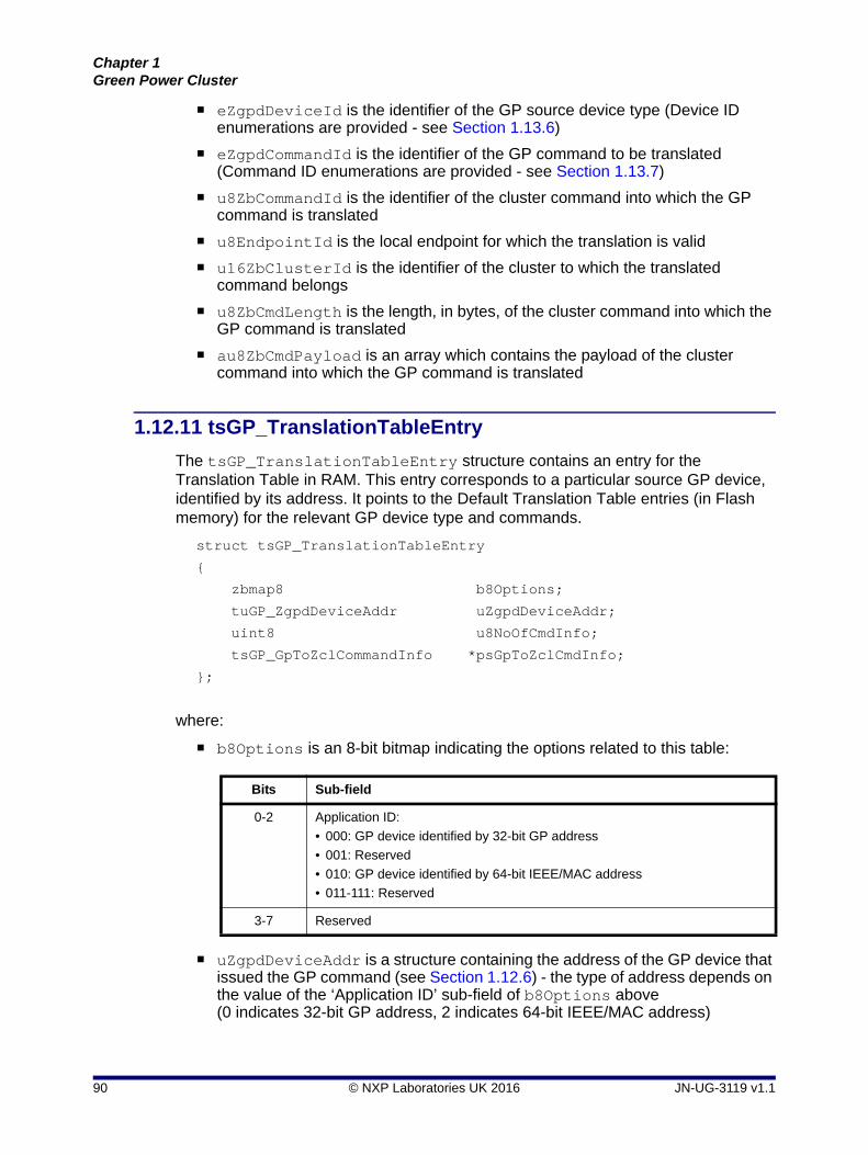
Chapter 1Green Power Cluster
eZgpdDeviceId is the identifier of the GP source device type (Device ID enumerations are provided - see Section 1.13.6)
eZgpdCommandId is the identifier of the GP command to be translated (Command ID enumerations are provided - see Section 1.13.7)
u8ZbCommandId is the identifier of the cluster command into which the GP command is translated
u8EndpointId is the local endpoint for which the translation is valid
u16ZbClusterId is the identifier of the cluster to which the translated command belongs
u8ZbCmdLength is the length, in bytes, of the cluster command into which the GP command is translated
au8ZbCmdPayload is an array which contains the payload of the cluster command into which the GP command is translated
1.12.11 tsGP_TranslationTableEntry
The tsGP_TranslationTableEntry structure contains an entry for the Translation Table in RAM. This entry corresponds to a particular source GP device, identified by its address. It points to the Default Translation Table entries (in Flash memory) for the relevant GP device type and commands.
struct tsGP_TranslationTableEntry
{
zbmap8 b8Options;
tuGP_ZgpdDeviceAddr uZgpdDeviceAddr;
uint8 u8NoOfCmdInfo;
tsGP_GpToZclCommandInfo *psGpToZclCmdInfo;
};
where:
b8Options is an 8-bit bitmap indicating the options related to this table:
uZgpdDeviceAddr is a structure containing the address of the GP device that issued the GP command (see Section 1.12.6) - the type of address depends on the value of the ‘Application ID’ sub-field of b8Options above (0 indicates 32-bit GP address, 2 indicates 64-bit IEEE/MAC address)
Bits Sub-field
0-2 Application ID:
• 000: GP device identified by 32-bit GP address
• 001: Reserved
• 010: GP device identified by 64-bit IEEE/MAC address
• 011-111: Reserved
3-7 Reserved
90 © NXP Laboratories UK 2016 JN-UG-3119 v1.1

ZigBee Green Power (for ZigBee 3.0)User Guide
u8NoOfCmdInfo is the number of commands in the Translation Table entry for this GP device (and therefore in the array pointed to by psGpToZclCmdInfo).
psGpToZclCmdInfo is a pointer to an array of Default Translation Table entries for the relevant GP device type and GP commands for this GP device (see Section 1.12.10).
1.12.12 tsGP_ZgpCommissionCmdPayload
The tsGP_ZgpCommissionCmdPayload structure contains the payload of a GP commissioning command issued by a GP device.
typedef struct
{
uint8 u8ApplicationInfo;
uint8 u8NoOfGPDCommands;
uint8 u8NoOfClusters;
teGP_ZgpdDeviceId eZgpdDeviceId;
zbmap8 b8Options;
zbmap8 b8ExtendedOptions;
uint16 u16ManufID;
uint16 u16ModelID;
uint32 u32ZgpdKeyMic;
uint32 u32ZgpdOutgoingCounter;
uint8 u8CommandList[GP_COMM_MAX_COUNT_COMMAND_ID];
uint16 u16ClusterList[GP_COMM_MAX_COUNT_CLUSTER];
tsZCL_Key sZgpdKey;
}tsGP_ZgpCommissionCmdPayload;
where:
u8ApplicationInfo is a bitmap indicating the application information fields that are contained in the GP commissioning command, as follows:
u8NoOfGPDCommands is the number of GP device commands contained in the u8CommandList[] field (if applicable).
u8NoOfClusters is the number of cluster IDs contained in the u16ClusterList[] field (if applicable).
Bit Field
0 Manufacturer ID (u16ManufID): 1 - present, 0 - not present
1 Model ID (u16ModelID): 1 - present, 0 - not present
2 GP device commands (u8CommandList[]): 1 - present, 0 - not present
3 Cluster list (u16ClusterList[]): 1 - present, 0 - not present
4-7 Reserved
JN-UG-3119 v1.1 © NXP Laboratories UK 2016 91

Chapter 1Green Power Cluster
eZgpdDeviceId is the identifier of the GP source device type (Device ID enumerations are provided - see Section 1.13.6)
b8Options is an 8-bit bitmap containing options related to this command, as follows:
b8ExtendedOptions is a 8-bit bitmap containing the extended options related to this command. This field will be present only if it is enabled in b8Options (above) and the GP device is capable of supporting security. The extended options are as follows (for further details, refer to the ZigBee Green Power Specification):
Bit Sub-field
0 Sequence number capabilities:
• 0: Uses random MAC sequence number
• 1: Uses incremental MAC sequence number
1 RxOn capability:
• 0: Receiver disabled in operational mode
• 1: Receiver enabled in operational mode
2 Reserved
3 Reserved
4 PAN ID request:
• 0: GP device is not requesting the PAN ID of the ZigBee network
• 1: GP device is requesting the PAN ID of the ZigBee network
5 GP security key request:
• 0: GP device is not requesting the GP security key
• 1: GP device is requesting the GP security key
6 Fixed location:
• 0: Node can change its position during operation of the network
• 1: Node is not expected to change its position during operation of the network
7 Extended options:
• 0: b8ExtendedOptions field (below) is not present in the structure
• 1: b8ExtendedOptions field (below) is present in the structure
Bits Use
0-1 Security level capabilities:
• 00: No security level specified in frame
• 01: 1-byte (LSB) of frame counter and short (2-byte) MIC
• 10: Full (4-byte) frame counter and full (4-byte) MIC
• 11: Encryption, full (4-byte) frame counter and full (4-byte) MIC
92 © NXP Laboratories UK 2016 JN-UG-3119 v1.1

ZigBee Green Power (for ZigBee 3.0)User Guide
u16ManufID is the manufacturer ID (if applicable) - it is typically present when the GP command list and/or cluster list are manufacturer-specific.
u16ModelID is the manufacturer-defined identifier of the product type (if applicable).
u32ZgpdKeyMic is the Message Integrity Code (MIC) for the encrypted GPD key (only present if encryption is enabled via bit 6 of b8ExtendedOptions).
u32ZgpdOutgoingCounter is the 32-bit security frame counter for the GP device (only present if enabled via bit 7 of b8ExtendedOptions).
u8CommandList[] is an array containing the GP device commands (if applicable), with one command per array element. The number of commands (and therefore array elements) is indicated in u8NoOfGPDCommands.The maximum number of commands supported is specified by GP_COMM_MAX_COUNT_COMMAND_ID (default is 4) and the application can set this value.
u16ClusterList[] is an array containing the cluster IDs (if applicable), with one cluster ID per array element. The number of clusters (and therefore array elements) is indicated in u8NoOfClusters.The maximum number of clusters supported is specified by GP_COMM_MAX_COUNT_CLUSTER (default is 4) and the application can set this value.
sZgpdKey is a GDP security key for the GP device (only present if enabled via bit 5 of b8ExtendedOptions).
2-4 Security key type:
• 000: No key
• 001: ZigBee network key
• 010: GPD group key
• 011: Network key derived from GPD group key
• 100: Individual out-of-box GPD key
• 101-110: Reserved
• 111: Individual derived GPD key
5 GPD key present:
• 0: sZgpdKey field (below) is not present
• 1: sZgpdKey field (below) is present
6 GPD key encryption:
• 0: GPD key is not encrypted
• 1: GPD key is encrypted
7 GPD outgoing counter present:
• 0: u32ZgpdOutgoingCounter field (below) is not present
• 1: u32ZgpdOutgoingCounter field (below) is present
Bits Use
JN-UG-3119 v1.1 © NXP Laboratories UK 2016 93

Chapter 1Green Power Cluster
1.12.13 tsGP_ZgpCommissioningNotificationCmdPayload
The tsGP_ZgpCommissioningNotificationCmdPayload structure contains the payload data for a commissioning notification, which is issued by a GP client to tunnel a GP command containing commissioning data.
typedef struct
{
teGP_ZgpdCommandId eZgpdCmdId;
uint8 u8GPP_GPD_Link;
uint16 u16ZgppShortAddr;
zbmap16 b16Options;
uint32 u32ZgpdSecFrameCounter;
uint32 u32Mic;
tuGP_ZgpdDeviceAddr uZgpdDeviceAddr;
tsZCL_OctetString sZgpdCommandPayload;
} tsGP_ZgpCommissioningNotificationCmdPayload;
where:
eZgpdCmdId is the identifier copied from the ‘Command ID’ field of the GP command (for the command enumerations, refer to Section 1.13.7).
u8GPP_GPD_Link indicates the ‘distance’ from the GP proxy node to the source GP device node to be used. This is a bitmap, as follows:
This is an optional field which will be valid if the ‘Rx After Tx’ sub-field of the b16Options field (see below) is set to ‘1’.
u16ZgppShortAddr is the network address of the GP proxy node to be used. This is an optional field which will be valid if the ‘Appoint Temp Master’ sub-field of the b16Options field (see below) is set to ‘1’.
b16Options is a 16-bit bitmap containing the options related to this command:
Bits Sub-field
0-5 Capped RSSI value
6-7 LQI value
Bits Sub-field
0-2 Application ID:
• 000: GP device identified by 32-bit GP address
• 001: Reserved
• 010: GP device identified by 64-bit IEEE/MAC address
• 011-111: Reserved
3 'Rx After Tx' capability of the GP device:
• 1: Receiver on after transmission
• 0: No receive capability
94 © NXP Laboratories UK 2016 JN-UG-3119 v1.1

ZigBee Green Power (for ZigBee 3.0)User Guide
u32ZgpdSecFrameCounter is the 32-bit security frame counter for the GP device
u32Mic is the Message Integrity Code (MIC) of the GP command from the GP device. This is an optional field which will be valid if the ‘Security Processing Failed’ sub-field of the b16Options field (see above) is set to ‘1’
uZgpdDeviceAddr contains the address copied from the ‘Source ID’ or ‘MAC Header Source Address’ field of the GP command from the GP device, depending on the value of the ‘Application ID’ sub-field in the GP command (0 indicates 32-bit GP address, 2 indicates 64-bit IEEE/MAC address)
sZgpdCommandPayload is a byte string containing the payload of the GP command, copied from the GP command’s ‘Payload’ field
4-5 Security Level (copied from GP frame received from GP device):
• 00: No security level specified in frame
• 01: Reserved
• 10: Full (4-byte) frame counter and full (4-byte) MIC
• 11: Encryption, full (4-byte) frame counter and full (4-byte) MIC
6-8 Security Key Type:
• 000: No key
• 001: ZigBee network key
• 010: GPD group key
• 011: Network key derived from GPD group key
• 100: Individual out-of-box GPD key
• 101-110: Reserved
• 111: Individual derived GPD key
For further details, refer to the ZigBee Green Power Specification.
9 Security Processing Failed:
• 1: Commissioning frame was secured but security check failed
• 0: Otherwise
10 Bidirectional capability of the Proxy device:
• 1: Supports bidirectional commissioning
• 0: Does not support bidirectional commissioning
11 Proxy device information present:
• 1: 16-bit network address and GPP-GPD link are present
• 0: 16-bit network address and GPP-GPD link are not present
12-15 Reserved
Bits Sub-field
JN-UG-3119 v1.1 © NXP Laboratories UK 2016 95

Chapter 1Green Power Cluster
1.12.14 tsGP_ZgpDecommissionIndication
The structure tsGP_ZgpDecommissionIndication contains the data for an event of the type E_GP_DECOMM_CMD_RCVD, which is generated when a GP decommissioning command arrives (directly from a source GP device or via a proxy node) and the local node is in commissioning mode.
typedef struct
{
uint8 u8ApplicationId;
tuGP_ZgpdDeviceAddr uZgpdDeviceAddr;
}tsGP_ZgpDecommissionIndication;
where :
u8ApplicationId is the 'Application ID' contained in the GP command, indicating the type of address used to identify the GP device:
0x00: 32-bit GP source address
0x02: 64-bit IEEE/MAC address
uZgpdDeviceAddr is a structure containing the address of the GP device that issued the GP command - see Section 1.12.6. The type of address depends on the value of u8ApplicationId above
1.12.15 tsGP_ZgpDataCmdWithAutoCommPayload
The tsGP_ZgpDataCmdWithAutoCommPayload structure contains the payload of a GP data command issued by a GP device.
typedef struct
{
teGP_ZgpdCommandId eZgpdCmdId;
uint8 u8ZgpdCmdPayloadLength;
uint8 *pu8ZgpdCmdPayload;
}tsGP_ZgpDataCmdWithAutoCommPayload;
where:
eZgpdCmdId is the identifier of GP command (for the command enumerations, refer to Section 1.13.7)
u8ZgpdCmdPayloadLength is the payload length, in bytes, of the GP command
pu8ZgpdCmdPayload is a pointer to the payload of the GP command
96 © NXP Laboratories UK 2016 JN-UG-3119 v1.1

ZigBee Green Power (for ZigBee 3.0)User Guide
1.12.16 tsGP_ZgpsTranslationUpdateEntry
The tsGP_ZgpsTranslationUpdateEntry structure contains the translation table entry data for inclusion in the payload of a Translation Update command (see Section 1.12.17).
typedef struct
{
uint8 u8Index;
teGP_ZgpdCommandId eZgpdCommandId;
uint8 u8EndpointId;
uint16 u16ProfileID;
uint16 u16ZbClusterId;
uint8 u8ZbCommandId;
uint8 u8ZbCmdLength ;
uint8 au8ZbCmdPayload[GP_MAX_ZB_CMD_PAYLOAD_LENGTH];
} tsGP_ZgpsTranslationUpdateEntry;
where:
u8Index is the index of translation table entry to be updated
u16ProfileID is the identifier of the ZigBee application profile supported on the target sink node
eZgpdCommandId is the GP command ID to be mapped (for the command enumerations, refer to Section 1.13.7)
u8EndpointId is the number of the application endpoint for which this translation valid
u16ZbClusterId is the identifier if the cluster which supports the translated command
u8ZbCommandId is the ZigBee command ID of the target command
u8ZbCmdLength is the length of the command (in bytes)
au8ZbCmdPayload is an array of bytes containing the command payload (the number of array elements is indicated in the u8ZbCmdLength field)
JN-UG-3119 v1.1 © NXP Laboratories UK 2016 97

Chapter 1Green Power Cluster
1.12.17 tsGP_ZgpTranslationUpdateCmdPayload
The tsGP_ZgpTranslationUpdateCmdPayload structure contains the payload of a Translation Update command, which is issued by a GP cluster client in order to update the translation table on a sink node.
typedef struct
{
zbmap16 b16Options;
tuGP_ZgpdDeviceAddr uZgpdDeviceAddr;
tsGP_ZgpsTranslationUpdateEntry asTranslationUpdateEntry[GP_MAX_TRANSLATION_UPDATE_ENTRY];
}tsGP_ZgpTranslationUpdateCmdPayload;
where:
b16Options is a 16-bit bitmap indicating the options related to the command:
uZgpdDeviceAddr is a structure containing the address of the GP device that issued the command (see Section 1.12.6) - the type of address depends on the value of the 'Application ID' sub-field of b16Options above (0 indicates 32-bit GP address, 2 indicates 64-bit IEEE/MAC address)
asTranslationUpdateEntry is an array of structures containing the data for the translation table entries to be updated
Bits Sub-field
0-2 Application ID:
• 000: GP device identified by 32-bit GP address
• 001: Reserved
• 010: GP device identified by 64-bit IEEE/MAC address
• 011-111: Reserved
3-4 Action:
• 00: Add translation table entry
• 01: Remove translation table entry
• 10: Replace translation table entry
• 11: Reserved
5-7 Number of translation table entries included in the command
8-15 Reserved
98 © NXP Laboratories UK 2016 JN-UG-3119 v1.1

ZigBee Green Power (for ZigBee 3.0)User Guide
1.12.18 tsGP_ZgpTransTableResponseCmdPayload
The tsGP_ZgpTransTableResponseCmdPayload structure contains the payload of a Translation Table Response, which is issued by a sink node as a result of a Translation Table Request.
typedef struct
{
uint8 u8Status;
zbmap8 b8Options;
uint8 u8TotalNumOfEntries;
uint8 u8StartIndex;
uint8 u8EntriesCount;
tsGP_ZgpsTransTblRspEntry asTransTblRspEntry[GP_MAX_TRANSLATION_RESPONSE_ENTRY];
}tsGP_ZgpTransTableResponseCmdPayload;
where:
u8Status is the status resulting from the corresponding Translation Table Request and can take the value SUCCESS or NOT_SUPPORTED
b8Options is a bitmap containing the following information:
u8TotalNumOfEntries is the total number of entries in the translation table on the sink node (from which the response originates)
u8StartIndex specifies the index in the translation table on the sink node (from which the response originates) of the first entry contained in the response
u8EntriesCount is the number of translation table entries contained in the array asTransTblRspEntry (it is the number of array elements)
asTransTblRspEntry is an array of structures containing the translation table entries reported in the response (see Section 1.12.24)
Bits Description
0-2 Application ID - Indicates the use of the GPD ID field in sTransTblRspEntry:
• 0b000 - contains Source ID of GP device
• 0b010 - contains IEEE address of GP device
All other values are reserved
3-7 Reserved
JN-UG-3119 v1.1 © NXP Laboratories UK 2016 99

Chapter 1Green Power Cluster
1.12.19 tsGP_ZgpsTranslationTableUpdate
The tsGP_ZgpsTranslationTableUpdate structure contains the data for an event of the type E_GP_TRANSLATION_TABLE_UPDATE, which is generated when a Translation Table Update command is received. This event will be generated for each translation received in the command and, therefore, this structure contains the data for one translation.
typedef struct
{
teGP_GreenPowerStatus eStatus;
teGP_TranslationTableUpdateAction eAction;
uint8 u8ApplicationId;
tuGP_ZgpdDeviceAddr uZgpdDeviceAddr;
tsGP_ZgpsTranslationUpdateEntry *psTranslationUpdateEntry;
} tsGP_ZgpsTranslationTableUpdate;;
where:
eStatus is a status field which should be updated by the application to indicate whether application is able to process the received translation successfully - the possible values are:
E_GP_TRANSLATION_UPDATE_SUCCESS
E_GP_TRANSLATION_UPDATE_FAIL
eAction specifies the action to be performed in the update, as one of:
E_GP_TRANSLATION_TABLE_ADD_ENTRY
E_GP_TRANSLATION_TABLE_REPLACE_ENTRY
E_GP_TRANSLATION_TABLE_REMOVE_ENTRY
For details of these actions, refer to Section 1.13.11.
u8ApplicationId indicates the type of address used to identify the GP device to which the translation table entry relates:
0x00: 32-bit GP source address
0x02: 64-bit IEEE/MAC address
uZgpdDeviceAddr is a union containing a 32-bit GP source address or the 64-bit IEEE/MAC address for the GP device (see Section 1.12.6), as specified by u8ApplicationId
psTranslationUpdateEntry is a pointer to the data to be used by the application to update the translation table entry (see Section 1.12.16)
100 © NXP Laboratories UK 2016 JN-UG-3119 v1.1

ZigBee Green Power (for ZigBee 3.0)User Guide
1.12.20 tsGP_ZgpPairingConfigCmdPayload
The tsGP_ZgpPairingConfigCmdPayload structure contains the payload data for a Pairing Configuration command, which is issued by a GP client in order to create/update/remove/replace a pairing entry in the sink table on a sink node.
typedef struct
{
uint8 u8Actions;
teGP_ZgpdDeviceId eZgpdDeviceId;
uint8 u8ZgpsGroupListEntries;
uint8 u8ForwardingRadius;
zbmap8 b8SecOptions;
uint8 u8NumberOfPairedEndpoints;
uint8 au8PairedEndpoints[GP_MAX_PAIRED_ENDPOINTS];
zbmap16 b16Options;
uint16 u16ZgpdAssignedAlias;
uint32 u32ZgpdSecFrameCounter;
tuGP_ZgpdDeviceAddr uZgpdDeviceAddr;
tsGP_ZgpsGroupList asZgpsGroupList[GP_MAX_SINK_GROUP_LIST];
tsZCL_Key sZgpdKey;
}tsGP_ZgpPairingConfigCmdPayload;
where:
u8Actions is an 8-bit bitmap containing the actions for the sink node to perform on receiving the Pairing Configuration command - enumerations are provided (see Section 1.13.12)
eZgpdDeviceId is the identifier of the GP source device type (Device ID enumerations are provided - see Section 1.13.6)
u8ZgpsGroupListEntries is the number of entries in the group list for the GP device
u8ForwardingRadius is the maximum radius (number of hops) for a groupcast communication of a command forwarded from the GP device
JN-UG-3119 v1.1 © NXP Laboratories UK 2016 101

Chapter 1Green Power Cluster
b8SecOptions is an 8-bit bitmap containing the security options for the GP device:
u8NumberOfPairedEndpoints is number of endpoints listed in the field au8PairedEndpoints (below)
au8PairedEndpoints is an array of the paired endpoint list for the GP device, where each array element contains the number of an endpoint with which the GP device can be paired
b16Options is a 16-bit bitmap containing options for the GP device:
Bits Sub-field
0-1 Security level:
• 00: No security
• 01: Reserved
• 10: Full (4-byte) frame counter and full (4-byte) MIC
• 11: Encryption, full (4-byte) frame counter and full (4-byte) MIC
2-4 Security key type:
• 000: No key
• 001: ZigBee network key
• 010: GPD group key
• 011: Network key derived from GPD group key
• 100: Individual out-of-box GPD key
• 101-110: Reserved
• 111: Individual derived GPD key
For further details, refer to the ZigBee Green Power Specification.
5-7 Reserved
Bits Sub-field
0-2 Application ID:
• 000: GP device identified by 32-bit GP address
• 001: Reserved
• 010: GP device identified by 64-bit IEEE/MAC address
• 011-111: Reserved
3-4 Communication mode:
• 00: Unicast forwarding of GP notifications by (all) proxies
• 01: Groupcast forwarding of GP notifications to a ‘derived’ group
• 10: Groupcast forwarding of GP notifications to a ‘pre-commissioned’ group
• 11: Unicast forwarding of GP notifications by proxies supporting the lightweight unicast feature (without observing the tunnelling delay and without the transmission/reception of the GP Tunnelling Stop command)
5 Sequence number capabilities:
• 0: Uses random MAC sequence number
• 1: Uses incremental MAC sequence number
6 RxOn capability:
• 0: Receiver disabled in operational mode
• 1: Receiver enabled in operational mode
102 © NXP Laboratories UK 2016 JN-UG-3119 v1.1

ZigBee Green Power (for ZigBee 3.0)User Guide
u16ZgpdAssignedAlias is an assigned 16-bit alias address for the GP device (if used)
u32ZgpdSecFrameCounter is a 32-bit security frame counter for the GP device (if used)
uZgpdDeviceAddr is a union containing a 32-bit GP address or the 64-bit IEEE/MAC address for the GP device (see Section 1.7.5)
asZgpsGroupList is an array of the group list for the GP device, where each array element is a structure containing a 16-bit group address and alias (see Section 1.12.9). Note that the:
The maximum number of entries in the array is 2, by default, but can be set to an alternative value using the compile-time option GP_MAX_SINK_GROUP_LIST (see Section 1.12.9)
The actual number of entries in the array is as indicated in the field u8ZgpsGroupListEntries
sZgpdKey is a security key for the GP device (not required if a common or derived key is used)
7 Fixed location:
• 0: Node can change its position during operation of the network
• 1: Node is not expected to change its position during operation of the network
8 Assigned alias:
• Uses assigned alias (specified in u16ZgpdAssignedAlias below)
• Does not use assigned alias
9 Security use:
• Uses security frame counter (specified in u32ZgpdSecFrameCounter below)
• Does not use security frame counter
10-15 Reserved
Bits Sub-field
JN-UG-3119 v1.1 © NXP Laboratories UK 2016 103

Chapter 1Green Power Cluster
1.12.21 tsGP_ZgpSinkTableRequestCmdPayload
The tsGP_ZgpPairingConfigCmdPayload structure contains the payload data for a Sink Table Request command, which requests the sink table entry corresponding to a specified GP address or all the sink table entries starting at a specified table index.
typedef struct
{
zbmap8 b8Options;
tuGP_ZgpdDeviceAddr uZgpdDeviceAddr;
uint8 u8Index;
}tsGP_ZgpSinkTableRequestCmdPayload;
where:
b8Options is a bitmap containing options concerned with the method of specifying the required sink table entry or entries:
uZgpdDeviceAddr is a structure containing the address of the GP device for which the sink table entry is required. This field is valid only if the request type specified in the b8Options bitmap is by address.
u8Index is the start index of the required sink table entries. This field is valid only if the request type specified in the b8Options bitmap is by index.
Bits Description
0-2 Application ID indicating the type of address used to identify the GP device:
• 0: 32-bit GP source address
• 2: 64-bit IEEE/MAC address
All other values are reserved.
3-4 Request type - method of identifying the relevant sink table entry or entries:
• 0: Address of source GP device
• 1: Start index in sink table
All other values are reserved.
5-7 Reserved
104 © NXP Laboratories UK 2016 JN-UG-3119 v1.1
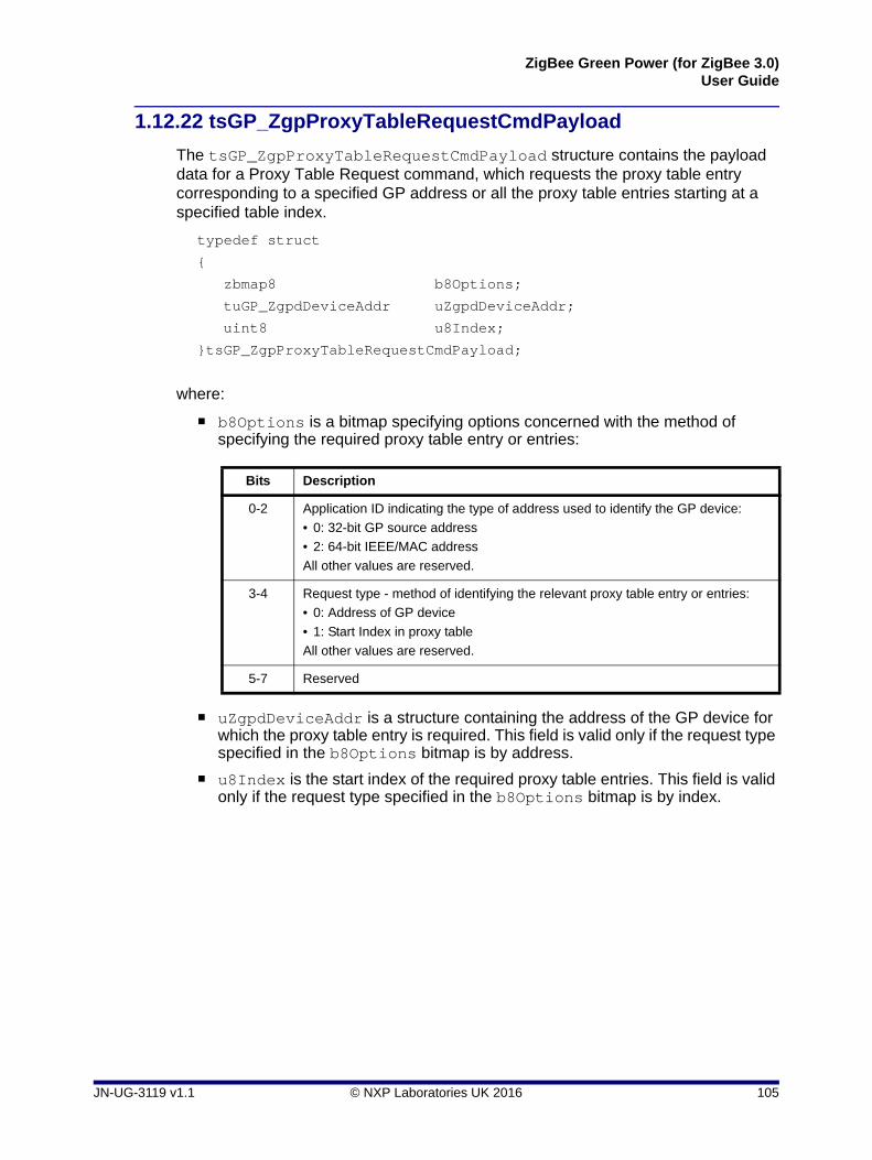
ZigBee Green Power (for ZigBee 3.0)User Guide
1.12.22 tsGP_ZgpProxyTableRequestCmdPayload
The tsGP_ZgpProxyTableRequestCmdPayload structure contains the payload data for a Proxy Table Request command, which requests the proxy table entry corresponding to a specified GP address or all the proxy table entries starting at a specified table index.
typedef struct
{
zbmap8 b8Options;
tuGP_ZgpdDeviceAddr uZgpdDeviceAddr;
uint8 u8Index;
}tsGP_ZgpProxyTableRequestCmdPayload;
where:
b8Options is a bitmap specifying options concerned with the method of specifying the required proxy table entry or entries:
uZgpdDeviceAddr is a structure containing the address of the GP device for which the proxy table entry is required. This field is valid only if the request type specified in the b8Options bitmap is by address.
u8Index is the start index of the required proxy table entries. This field is valid only if the request type specified in the b8Options bitmap is by index.
Bits Description
0-2 Application ID indicating the type of address used to identify the GP device:
• 0: 32-bit GP source address
• 2: 64-bit IEEE/MAC address
All other values are reserved.
3-4 Request type - method of identifying the relevant proxy table entry or entries:
• 0: Address of GP device
• 1: Start Index in proxy table
All other values are reserved.
5-7 Reserved
JN-UG-3119 v1.1 © NXP Laboratories UK 2016 105

Chapter 1Green Power Cluster
1.12.23 tsGP_ZgpsPairingConfigCmdRcvd
The tsGP_ZgpsPairingConfigCmdRcvd structure contains the data for an event of the type E_GP_PAIRING_CONFIGURATION_CMD_RCVD, which is generated when a Pairing Configuration command is received.
typedef struct
{
teGP_GreenPowerPairingConfigAction eAction;
teGP_PairingConfigTranslationTableAction
eTranslationTableAction;
teGP_ZgpdDeviceId eZgpdDeviceId;
teGP_GreenPowerCommunicationMode eCommunicationMode;
uint8 u8ApplicationId;
tuGP_ZgpdDeviceAddr uZgpdDeviceAddr;
uint8 u8NumberOfPairedEndpoints;
uint8 au8PairedEndpointList[GP_MAX_PAIRED_ENDPOINTS];
uint8 u8SinkGroupListEntries;
tsGP_ZgpsGroupList asSinkGroupList[GP_MAX_SINK_GROUP_LIST];
} tsGP_ZgpsPairingConfigCmdRcvd;
where:
eAction is a value indicating the action to perform as a result of the received command - enumerations are provided (see Section 1.13.12)
eTranslationTableAction is a value indicating the action to be performed in the translation table as a result of the received command - enumerations are provided (see Section 1.13.13)
eZgpdDeviceId is the identifier of the GP source device type - Device ID enumerations are provided (see Section 1.13.6)
eCommunicationMode indicates the communication mode used by the Pairing Configuration command:
00: Unicast forwarding by (all) proxies
01: Groupcast forwarding to a ‘derived’ group
10: Groupcast forwarding to a ‘pre-commissioned’ group
11: Unicast forwarding of GP notifications by proxies supporting the lightweight unicast feature (without observing the tunnelling delay and without the transmission/reception of the GP Tunnelling Stop command)
u8ApplicationId indicates the type of address used to identify the GP device in the command:
0x00: 32-bit GP source address
0x02: 64-bit IEEE/MAC address
106 © NXP Laboratories UK 2016 JN-UG-3119 v1.1
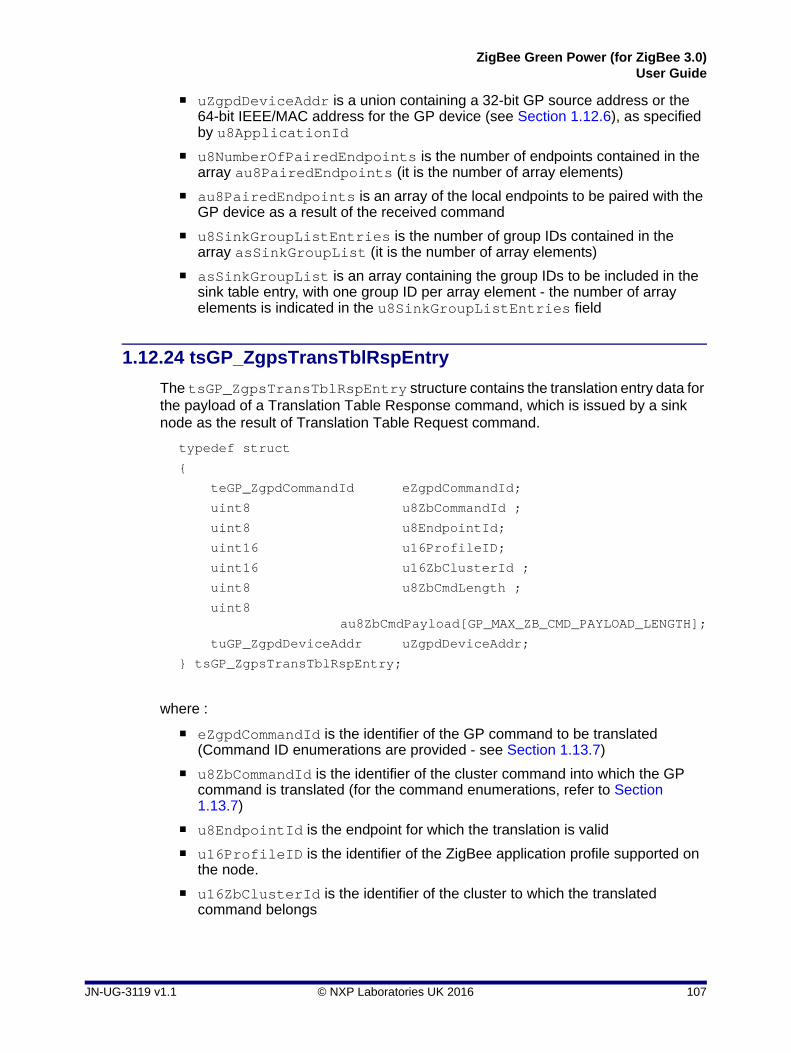
ZigBee Green Power (for ZigBee 3.0)User Guide
uZgpdDeviceAddr is a union containing a 32-bit GP source address or the 64-bit IEEE/MAC address for the GP device (see Section 1.12.6), as specified by u8ApplicationId
u8NumberOfPairedEndpoints is the number of endpoints contained in the array au8PairedEndpoints (it is the number of array elements)
au8PairedEndpoints is an array of the local endpoints to be paired with the GP device as a result of the received command
u8SinkGroupListEntries is the number of group IDs contained in the array asSinkGroupList (it is the number of array elements)
asSinkGroupList is an array containing the group IDs to be included in the sink table entry, with one group ID per array element - the number of array elements is indicated in the u8SinkGroupListEntries field
1.12.24 tsGP_ZgpsTransTblRspEntry
The tsGP_ZgpsTransTblRspEntry structure contains the translation entry data for the payload of a Translation Table Response command, which is issued by a sink node as the result of Translation Table Request command.
typedef struct
{
teGP_ZgpdCommandId eZgpdCommandId;
uint8 u8ZbCommandId ;
uint8 u8EndpointId;
uint16 u16ProfileID;
uint16 u16ZbClusterId ;
uint8 u8ZbCmdLength ;
uint8 au8ZbCmdPayload[GP_MAX_ZB_CMD_PAYLOAD_LENGTH];
tuGP_ZgpdDeviceAddr uZgpdDeviceAddr;
} tsGP_ZgpsTransTblRspEntry;
where :
eZgpdCommandId is the identifier of the GP command to be translated (Command ID enumerations are provided - see Section 1.13.7)
u8ZbCommandId is the identifier of the cluster command into which the GP command is translated (for the command enumerations, refer to Section 1.13.7)
u8EndpointId is the endpoint for which the translation is valid
u16ProfileID is the identifier of the ZigBee application profile supported on the node.
u16ZbClusterId is the identifier of the cluster to which the translated command belongs
JN-UG-3119 v1.1 © NXP Laboratories UK 2016 107

Chapter 1Green Power Cluster
u8ZbCmdLength is the length, in bytes, of the cluster command into which the GP command is translated
au8ZbCmdPayload is an array which contains the payload of the cluster command into which the GP command is translated
uZgpdDeviceAddr is a union containing a 32-bit GP address or the 64-bit IEEE/MAC address for the GP device (see Section 1.12.6)
1.12.25 tsGP_SinkTableRespCmdPayload
The structure tsGP_SinkTableRespCmdPayload contains the data for an event of the type E_GP_ZGPD_SINK_TABLE_RESPONSE_RCVD, which is generated on client when a GP Sink Table Response is received from the server in reply to a GP Sink Table Request.
typedef struct
{
uint8 u8Status;
uint8 u8TotalNoOfEntries;
uint8 u8StartIndex;
uint8 u8EntriesCount;
uint16 u16SizeOfSinkTableEntries;
uint8 *puSinkTableEntries;
}tsGP_SinkTableRespCmdPayload;
where:
u8Status is the status of Sink Table Request and can take the value E_ZCL_SUCCESS or E_ZCL_CMDS_NOT_FOUND.
u8TotalNoOfEntries is the total number of sink table entries present on the server.
u8StartIndex is the position of first sink table entry included in the response (when requested by index). The value 0 corresponds to the first non-empty entry in the sink table.
u8EntriesCount is the number of sink table entries included in the response.
puSinkTableEntries is a pointer to the returned sink table entries - the format is described in the ZigBee Green Power specification.
108 © NXP Laboratories UK 2016 JN-UG-3119 v1.1

ZigBee Green Power (for ZigBee 3.0)User Guide
1.12.26 tsGP_ ProxyTableRespCmdPayload
The structure tsGP_ ProxyTableRespCmdPayload contains the data for an event of the type E_GP_ZGPD_PROXY_TABLE_RESPONSE_RCVD, which is generated on a server/commissioning tool when a Proxy Table Response is received from a client in reply to a Proxy Table Request.
typedef struct tsGP_ProxyTableRespCmdPayload
{
uint8 u8Status;
uint8 u8TotalNoOfEntries;
uint8 u8StartIndex;
uint8 u8EntriesCount;
uint16 u16SizeOfProxyTableEntries;
uint8 *puProxyTableEntries;
}tsGP_ProxyTableRespCmdPayload;
where:
u8Status is the status of Proxy Table Request and can take the value E_ZCL_ SUCCESS or E_ZCL_CMDS_NOT_FOUND.
u8TotalNoOfEntries is the total number of proxy table entries present on the client.
u8StartIndex is the position of first proxy table entry included in the response (when requested by index). The value 0 corresponds to the first non-empty entry in the proxy table.
u8EntriesCount is the number of proxy table entries included in the response.
puProxyTableEntries is a pointer to the returned proxy table entries - the format is described in the ZigBee Green Power specification.
1.12.27 tsGP_ ZgpResponseCmdPayload
The structure tsGP_ZgpResponseCmdPayload contains the data for an event of the type E_GP_RESPONSE_RCVD, which is generated on a client when a GP Response is received (from a server) which is to be passed to a GP device.
typedef struct
{
zbmap8 b8Options;
zbmap8 b8TempMasterTxChannel;
teGP_ZgpdCommandId eZgpdCmdId;
uint16 u16TempMasterShortAddr;
tuGP_ZgpdDeviceAddr uZgpdDeviceAddr;
tsZCL_OctetString sZgpdCommandPayload;
}tsGP_ZgpResponseCmdPayload;
JN-UG-3119 v1.1 © NXP Laboratories UK 2016 109

Chapter 1Green Power Cluster
where:
b8Options is a bitmap containing the following options:
b8TempMasterTxChannel is the number of the radio channel on which the response will be sent in a GP device frame to the GP device.
eZgpdCmdId is the GP command ID (for the command enumerations, refer to Section 1.13.7).
u16TempMasterShortAddr is the address of the proxy node which will transmit the GP device frame to the GP device.
uZgpdDeviceAddr is a structure containing the target GP device address (see Section 1.12.6).
sZgpdCommandPayload is the command payload for the GP device frame.
Bits Name Description
0-2 Application ID Indicates whether bit 3 (below) is used, and deter-mines the length and meaning of the uZgpdDe-viceAddr field:
• 000 - uZgpdDeviceAddr contains the GP device’s source ID and is 4 bytes long, and Bit 3 is not used.
• 010 - uZgpdDeviceAddr contains the GP device’s IEEE/MAC address and is 8 bytes long, and Bit 3 is used.
3 Transmit on endpoint match Indicates whether a matching endpoint number is needed for GP Response delivery:
• 0 - Endpoint number is not needed
• 1 - If Application ID (bits 0-2) is 010, the GP Response will be delivered only to a GP device with a matching endpoint number
4-7 Reserved -
110 © NXP Laboratories UK 2016 JN-UG-3119 v1.1

ZigBee Green Power (for ZigBee 3.0)User Guide
1.12.28 tsGP_ZgpNotificationCmdPayload
The structure tsGP_ZgpNotificationCmdPayload contains the data for an event of the type E_GP_NOTIFICATION_RCVD, which is generated on the server when a GP Notification command is received from a client that has received a GP command.
typedef struct
{
teGP_ZgpdCommandId eZgpdCmdId;
uint8 u8GPP_GPD_Link;
uint16 u16ZgppShortAddr;
zbmap16 b16Options;
uint32 u32ZgpdSecFrameCounter;
tuGP_ZgpdDeviceAddr uZgpdDeviceAddr;
tsZCL_OctetString sZgpdCommandPayload;
}tsGP_ZgpNotificationCmdPayload;
where:
eZgpdCmdId is the command ID of the GP command (for the command enumerations, refer to Section 1.13.7).
u8GPP_GPD_Link indicates the quality of the GP device frame in which the command was received.
u16ZgppShortAddr is the 16-bit network address of the proxy node that received the GP command and sent the GP Notification command.
b16Options is a bitmap containing the following options:
Bits Name Description
0-2 Application ID Determines the length and meaning of the uZgpd-DeviceAddr field, and whether the target endpoint number is present in the GP command:
• 000 - uZgpdDeviceAddr contains the GP device’s source ID and is 4 bytes long, and endpoint number is absent
• 010 - uZgpdDeviceAddr contains the GP device’s IEEE/MAC address and is 8 bytes long, and endpoint number is present
3 Unicast If set (to 1), indicates that a sink node is paired with the GP device, requiring a unicast to the sink node.
4 Derived Group If set (to 1), indicates that a derived group of sink nodes is associated with the GP device, requiring a groupcast.
5 Commissioned Group If set (to 1), indicates that a pre-commissioned group of sink nodes is associated with the GP device, requiring a groupcast.
JN-UG-3119 v1.1 © NXP Laboratories UK 2016 111

Chapter 1Green Power Cluster
u32ZgpdSecFrameCounter is the frame counter value of the received GP command.
uZgpdDeviceAddr is a structure containing the source GP device address (see Section 1.12.6).
sZgpdCommandPayload contains the command payload of the GP device frame.
6-7 Security Level Security level of received GP command:
• 00: No security
• 01: Reserved
• 10: Full (4-byte) frame counter and full (4-byte) MIC
• 11: Encryption, full (4-byte) frame counter and full (4-byte) MIC
8-10 Security Key Type Security key type for received GP command:
• 000: No key
• 001: ZigBee network key
• 010: GPD group key
• 011: Network key derived from GPD group key
• 100: Individual out-of-box GPD key
• 101-110: Reserved
• 111: Individual derived GPD key
For further details, refer to the ZigBee Green Power Specification.
11 Rx After Tx If set (to 1), indicates that the receiver is on after a transmit on the GP device.
12 GP Tx Queue Full If set (to 1), indicates that the proxy node can still receive and store a GP Response for the GP device.
13 Bidirectional capability If set (to 1), indicates that the node that sent the GP Notification command does NOT support bi-direc-tional communication. Should always be set to 0 in the current GP version.
14 Proxy info present If set (to 1), indicates that the fields u8GPP_GPD_Link and u16ZgppShortAddr (above) are present.
15 Reserved -
Bits Name Description
112 © NXP Laboratories UK 2016 JN-UG-3119 v1.1
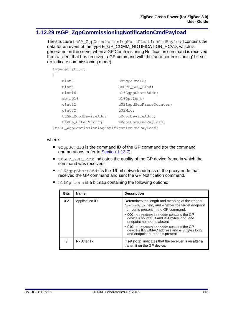
ZigBee Green Power (for ZigBee 3.0)User Guide
1.12.29 tsGP_ZgpCommissioningNotificationCmdPayload
The structure tsGP_ZgpCommissioningNotificationCmdPayload contains the data for an event of the type E_GP_COMM_NOTIFICATION_RCVD, which is generated on the server when a GP Commissioning Notification command is received from a client that has received a GP command with the ‘auto-commissioning’ bit set (to indicate commissioning mode).
typedef struct
{
uint8 u8ZgpdCmdId;
uint8 u8GPP_GPD_Link;
uint16 u16ZgppShortAddr;
zbmap16 b16Options;
uint32 u32ZgpdSecFrameCounter;
uint32 u32Mic;
tuGP_ZgpdDeviceAddr uZgpdDeviceAddr;
tsZCL_OctetString sZgpdCommandPayload;
}tsGP_ZgpCommissioningNotificationCmdPayload;
where:
eZgpdCmdId is the command ID of the GP command (for the command enumerations, refer to Section 1.13.7).
u8GPP_GPD_Link indicates the quality of the GP device frame in which the command was received.
u16ZgppShortAddr is the 16-bit network address of the proxy node that received the GP command and sent the GP Notification command.
b16Options is a bitmap containing the following options:
Bits Name Description
0-2 Application ID Determines the length and meaning of the uZgpd-DeviceAddr field, and whether the target endpoint number is present in the GP command:
• 000 - uZgpdDeviceAddr contains the GP device’s source ID and is 4 bytes long, and endpoint number is absent
• 010 - uZgpdDeviceAddr contains the GP device’s IEEE/MAC address and is 8 bytes long, and endpoint number is present
3 Rx After Tx If set (to 1), indicates that the receiver is on after a transmit on the GP device.
JN-UG-3119 v1.1 © NXP Laboratories UK 2016 113

Chapter 1Green Power Cluster
u32ZgpdSecFrameCounter is the frame counter value of the received GP command.
u32Mic contains the MIC when the security processing fails.
uZgpdDeviceAddr is a structure containing the source GP device address (see Section 1.12.6).
sZgpdCommandPayload contains the command payload of the GP device frame.
4-5 Security Level Security level of received GP command:
• 00: No security
• 01: Reserved
• 10: Full (4-byte) frame counter and full (4-byte) MIC
• 11: Encryption, full (4-byte) frame counter and full (4-byte) MIC
6-8 Security Key Type Security key type for received GP command:
• 000: No key
• 001: ZigBee network key
• 010: GPD group key
• 011: Network key derived from GPD group key
• 100: Individual out-of-box GPD key
• 101-110: Reserved
• 111: Individual derived GPD key
For further details, refer to the ZigBee Green Power Specification.
9 Security processing failed If set (to 1), indicates that the security processing of the received GP command has failed.
10 Bidirectional capability If set (to 1), indicates that the node that sent the GP Commissioning Notification command does NOT support bi-directional communication. Should always be set to 0 in the current GP version.
11 Proxy info present If set (to 1), indicates that the fields u8GPP_GPD_Link and u16ZgppShortAddr (above) are present.
12-15 Reserved -
Bits Name Description
114 © NXP Laboratories UK 2016 JN-UG-3119 v1.1

ZigBee Green Power (for ZigBee 3.0)User Guide
1.12.30 tsGP_ZgpPairingCmdPayload
The structure tsGP_ZgpPairingCmdPayload contains the data for an event of the type E_GP_PAIRING_CMD_RCVD, which is generated on a client when a GP Pairing command is received from the server.
typedef struct
{
uint8 u8DeviceId;
uint8 u8ForwardingRadius;
uint16 u16SinkGroupID;
uint16 u16AssignedAlias;
zbmap24 b24Options;
uint32 u32ZgpdSecFrameCounter;
uint16 u16SinkNwkAddress;
uint64 u64SinkIEEEAddress;
tuGP_ZgpdDeviceAddr uZgpdDeviceAddr;
tsZCL_Key sZgpdKey;
}tsGP_ZgpPairingCmdPayload;
where:
u8DeviceId is the device ID for the GP device to which the pairing relates.
u8ForwardingRadius is the radius (maximum number of hops) in the network for groupcast forwarding of the GP device frame.
u16SinkGroupID is the address of the group to which the sink node that originated the GP Pairing command belongs.
u16AssignedAlias contains the ‘assigned alias’ (pre-commissioned) network address to be used for this GP device instead of the ‘derived’ network address.
b24Options is a bitmap containing the following options:
Bits Name Description
0-2 Application ID Determines the length and meaning of the uZgpd-DeviceAddr field, and whether the target endpoint number is present in the GP command:
• 000 - uZgpdDeviceAddr contains the GP device’s source ID and is 4 bytes long, and endpoint number is absent
• 010 - uZgpdDeviceAddr contains the GP device’s IEEE/MAC address and is 8 bytes long, and endpoint number is present
3 Add Sink Indicates whether the sink node is requesting the addition or removal of a pairing for the GP device.
• 1 - Add pairing
• 0 - Remove pairing
JN-UG-3119 v1.1 © NXP Laboratories UK 2016 115

Chapter 1Green Power Cluster
4 Remove GPD Indicates whether the sink node is requesting that the GP device is removed from the network.
• 1 - Remove GP device from network
• 0 - Do not remove GP device from network
5-6 Communication mode Contains information about the accepted tunnelling modes for this GP device:
• 00: Unicast forwarding of GP notifications by (all) proxies
• 01: Groupcast forwarding of GP notifications to a 'derived' group
• 10: Groupcast forwarding of GP notifications to a 'pre-commissioned' group
• 11: Unicast forwarding of GP notifications by proxies supporting the lightweight unicast feature (without observing the tunnelling delay and without the transmission/reception of the GP Tunnelling Stop command)
7 GPD Fixed If set (to 1), indicates that the GP device is fixed.
8 GPD MAC sequence num-ber capabilities
If set (to 1), indicates that the GP device supports MAC sequence numbers.
9-10 Security Level Security level supported by the GP device:
• 00: No security
• 01: Reserved
• 10: Full (4-byte) frame counter and full (4-byte) MIC
• 11: Encryption, full (4-byte) frame counter and full (4-byte) MIC
11-13 Security Key Type Security key type supported by the GP device:
• 000: No key
• 001: ZigBee network key
• 010: GPD group key
• 011: Network key derived from GPD group key
• 100: Individual out-of-box GPD key
• 101-110: Reserved
• 111: Individual derived GPD key
For further details, refer to the ZigBee Green Power Specification.
14 GPD security Frame Coun-ter present
If set (to 1), indicates that a security frame counter is present.
15 GPD security key present If set (to 1), indicates that a security key is present.
16 Assigned Alias present If set (to 1), indicates that an ‘assigned alias’ is pre-sent.
17 Forwarding Radius present If set (to 1), indicates that a forwarding radius is pre-sent (specified in the field u8ForwardingRadius).
18-23 Reserved -
Bits Name Description
116 © NXP Laboratories UK 2016 JN-UG-3119 v1.1

ZigBee Green Power (for ZigBee 3.0)User Guide
u32ZgpdSecFrameCounter is the frame counter value for the received GP command.
u32Mic is the MIC when the security processing fails.
u16SinkNwkAddress contains the network address of the sink node - it is present if full or lightweight unicast communication mode is requested.
u64SinkIEEEAddress contains the IEEE/MAC address of the sink node - it is present if full or lightweight unicast communication mode is requested.
uZgpdDeviceAddr is a structure containing the GP device address (see Section 1.12.6).
sZgpdKey is the key to be used for securing messages exchanged with this GP device.
JN-UG-3119 v1.1 © NXP Laboratories UK 2016 117

Chapter 1Green Power Cluster
1.13 Enumerations
1.13.1 'Attribute ID' Enumerations
The following structure contains the enumerations used to identify the attributes of the Green Power cluster.
typedef enum PACK
{
/* Server Attribute IDs */
E_CLD_GP_ATTR_ZGPS_MAX_SINK_TABLE_ENTRIES = 0x0000,
E_CLD_GP_ATTR_ZGPS_SINK_TABLE,
E_CLD_GP_ATTR_ZGPS_COMMUNICATION_MODE,
E_CLD_GP_ATTR_ZGPS_COMMISSIONING_EXIT_MODE,
E_CLD_GP_ATTR_ZGPS_COMMISSIONING_WINDOW,
E_CLD_GP_ATTR_ZGPS_SECURITY_LEVEL,
E_CLD_GP_ATTR_ZGPS_FEATURES,
E_CLD_GP_ATTR_ZGPS_ACTIVE_FEATURES,
/* Client Attribute IDs */
E_CLD_GP_ATTR_ZGPP_MAX_PROXY_TABLE_ENTRIES = 0x0010,
E_CLD_GP_ATTR_ZGPP_PROXY_TABLE,
E_CLD_GP_ATTR_ZGPP_NOTIFICATION_RETRY_NUMBER,
E_CLD_GP_ATTR_ZGPP_NOTIFICATION_RETRY_TIMER,
E_CLD_GP_ATTR_ZGPP_MAX_SEARCH_COUNTER,
E_CLD_GP_ATTR_ZGPP_BLOCKED_ZGPD_ID,
E_CLD_GP_ATTR_ZGPP_FUNCTIONALITY,
E_CLD_GP_ATTR_ZGPP_ACTIVE_FUNCTIONALITY,
/* Shared Attributes between server and client */
E_CLD_GP_ATTR_ZGP_SHARED_SECURITY_KEY_TYPE = 0x0020,
E_CLD_GP_ATTR_ZGP_SHARED_SECURITY_KEY,
E_CLD_GP_ATTR_ZGP_LINK_KEY
}teGP_GreenPowerClusterAttrIds;
The attributes corresponding to the above enumerations are listed in Table 6 below. For details of these attributes, refer to Section 1.3.
118 © NXP Laboratories UK 2016 JN-UG-3119 v1.1

ZigBee Green Power (for ZigBee 3.0)User Guide
Enumeration Attribute
E_CLD_GP_ATTR_ZGPS_MAX_SINK_TABLE_ENTRIES u8ZgpsMaxSinkTableEntries
E_CLD_GP_ATTR_ZGPS_SINK_TABLE sSinkTable
E_CLD_GP_ATTR_ZGPS_COMMUNICATION_MODE b8ZgpsCommunicationMode
E_CLD_GP_ATTR_ZGPS_COMMISSIONING_EXIT_MODE b8ZgpsCommissioningExitMode
E_CLD_GP_ATTR_ZGPS_COMMISSIONING_WINDOW u16ZgpsCommissioningWindow
E_CLD_GP_ATTR_ZGPS_SECURITY_LEVEL b8ZgpsSecLevel
E_CLD_GP_ATTR_ZGPS_FEATURES b24ZgpsFeatures
E_CLD_GP_ATTR_ZGPS_ACTIVE_FEATURES b24ZgpsActiveFeatures
E_CLD_GP_ATTR_ZGPP_MAX_PROXY_TABLE_ENTRIES u8ZgppMaxProxyTableEntries
E_CLD_GP_ATTR_ZGPP_PROXY_TABLE sProxyTable
E_CLD_GP_ATTR_ZGPP_NOTIFICATION_RETRY_NUMBER u8ZgppNotificationRetryNumber
E_CLD_GP_ATTR_ZGPP_NOTIFICATION_RETRY_TIMER u8ZgppNotificationRetryTimer
E_CLD_GP_ATTR_ZGPP_MAX_SEARCH_COUNTER u8ZgppMaxSearchCounter
E_CLD_GP_ATTR_ZGPP_BLOCKED_ZGPD_ID sZgppBlockedGpdID
E_CLD_GP_ATTR_ZGPP_FUNCTIONALITY b24ZgppFunctionality
E_CLD_GP_ATTR_ZGPP_ACTIVE_FUNCTIONALITY b24ZgppActiveFunctionality
E_CLD_GP_ATTR_ZGP_SHARED_SECURITY_KEY_TYPE b8ZgpSharedSecKeyType
E_CLD_GP_ATTR_ZGP_SHARED_SECURITY_KEY sZgpSharedSecKey
E_CLD_GP_ATTR_ZGP_LINK_KEY sZgpLinkKey
Table 6: Green Power Attribute ID Enumerations
JN-UG-3119 v1.1 © NXP Laboratories UK 2016 119

Chapter 1Green Power Cluster
1.13.2 'Green Power Event' Enumerations
The event types generated by the Green Power cluster are enumerated in the teGP_GreenPowerCallBackEventType structure below.
typedef enum PACK
{
E_GP_COMMISSION_DATA_INDICATION = 0x00,
E_GP_COMMISSION_MODE_ENTER,
E_GP_COMMISSION_MODE_EXIT,
E_GP_CMD_UNSUPPORTED_PAYLOAD_LENGTH,
E_GP_SINK_PROXY_TABLE_ENTRY_ADDED,
E_GP_SINK_PROXY_TABLE_FULL,
E_GP_ZGPD_COMMAND_RCVD,
E_GP_ZGPD_CMD_RCVD_WO_TRANS_ENTRY,
E_GP_ADDING_GROUP_TABLE_FAIL,
E_GP_RECEIVED_CHANNEL_REQUEST,
E_GP_TRANSLATION_TABLE_RESPONSE_RCVD,
E_GP_TRANSLATION_TABLE_UPDATE,
E_GP_SECURITY_LEVEL_MISMATCH,
E_GP_SECURITY_PROCESSING_FAILED,
E_GP_REMOVING_GROUP_TABLE_FAIL,
E_GP_PAIRING_CONFIGURATION_CMD_RCVD,
E_GP_PERSIST_SINK_PROXY_TABLE,
E_GP_SUCCESS_CMD_RCVD,
E_GP_DECOMM_CMD_RCVD,
E_GP_SHARED_SECURITY_KEY_TYPE_IS_NOT_ENABLED,
E_GP_SHARED_SECURITY_KEY_IS_NOT_ENABLED,
E_GP_LINK_KEY_IS_NOT_ENABLED,
E_GP_ZGPD_SINK_TABLE_RESPONSE_RCVD,
E_GP_ZGPD_PROXY_TABLE_RESPONSE_RCVD,
E_GP_NOTIFICATION_RCVD,
E_GP_COMM_NOTIFICATION_RCVD,
E_GP_RESPONSE_RCVD,
E_GP_PAIRING_CMD_RCVD,
E_GP_PAIRING_CONFIG_CMD_RCVD,
E_GP_CBET_ENUM_END
}teGP_GreenPowerCallBackEventType;
120 © NXP Laboratories UK 2016 JN-UG-3119 v1.1

ZigBee Green Power (for ZigBee 3.0)User Guide
The above event types are described in Table 7 below. For further information on these events and event handling, refer to Section 1.9.
Enumeration Event Description
E_GP_COMMISSION_DATA_INDICATION Generated on a Green Power cluster server on receiving a commissioning command (GP frame with auto-commis-sioning flag set to ‘1’) directly from a GP device or via a proxy node, with the server in commissioning mode.
E_GP_COMMISSION_MODE_ENTER Generated on the Green Power cluster on receiving a Proxy Commissioning Mode command with the ‘Enter’ action.
E_GP_COMMISSION_MODE_EXIT Generated on the Green Power cluster on receiving a Proxy Commissioning Mode command with the ‘Exit’ action or when the commissioning window timeout has expired or when node pairing has been successfully com-pleted.
E_GP_CMD_UNSUPPORTED_PAYLOAD_LENGTH Generated on a Green Power cluster on receiving a GP frame with a payload which is longer than the maximum set in the zcl_options.h file (see Section 1.14).
E_GP_SINK_TABLE_ENTRY_ADDED Generated on a Green Power cluster server when a sink table entry is created as the result of receiving a commis-sioning command (GP frame with auto-commissioning flag set to ‘1’) from a GP device, with the server is in com-missioning mode.
E_GP_SINK_TABLE_FULL Generated on a Green Power cluster server on receiving a commissioning command (GP frame with auto-commis-sioning flag set to ‘1’) from a GP device, with the server is in commissioning mode, but there is no free entry remain-ing in the sink table.
E_GP_ZGPD_COMMAND_RCVD Generated on a Green Power cluster server when a GP command has been received (either directly from the GP device or indirectly via a proxy node), and entries for the node/command have been found in the local sink and translation tables.
E_GP_ZGPD_CMD_RCVD_WO_TRANS_ENTRY Generated on a Green Power cluster server when a GP command has been received (either directly from the GP device or indirectly via a proxy node) but there is no matching translation table entry for the node/command or a NULL translation table pointer was passed to the GP cluster via eGP_RegisterComboBasicEndPoint() dur-ing initialisation.
E_GP_ADDING_GROUP_TABLE_FAIL Generated on a Green Power cluster server on receiving a commissioning command (GP frame with auto-commis-sioning flag set to ‘1’), with the server in commissioning mode, but the cluster fails to add a group table entry.
E_GP_RECEIVED_CHANNEL_REQUEST Generated on a Green Power cluster client on a Proxy Basic device when a Channel Request from a GP device has been received during commissioning.
Table 7: Green Power Event Enumerations
JN-UG-3119 v1.1 © NXP Laboratories UK 2016 121

Chapter 1Green Power Cluster
E_GP_TRANSLATION_TABLE_RESPONSE_RCVD Generated on a Green Power cluster client when a Trans-lation Table Response is received.
E_GP_TRANSLATION_TABLE_UPDATE Generated on a Green Power cluster server when a Translation Table Update command is received. This event will be generated for each translation in the received command.
E_GP_SECURITY_LEVEL_MISMATCH Generated on a Green Power cluster server or client when a received GP frame (directly from a GP device) does not support the minimum security level required by the GP infrastructure device.
E_GP_SECURITY_PROCESSING_FAILED Generated on a Green Power cluster server or client when a received GP frame (directly from a GP device) fails the security processing performed by the GP infra-structure device.
E_GP_REMOVING_GROUP_TABLE_FAIL Generated on a Green Power cluster server when a Pair-ing Configuration command is received in which the action field is one of...REPLACE_SINK_TABLE_ENTRY...REMOVE_SINK_TABLE_ENTRY...CONFIG_REMOVE_GPD (each prefixed with E_GP_PAIRING_CONFIG_) but the cluster fails to remove a group table entry.
E_GP_PAIRING_CONFIGURATION_CMD_RCVD Generated on a Green Power cluster server when a Pair-ing Configuration command is received. The application should then add or delete the relevant translation table entry.
E_GP_PERSIST_ATTRIBUTE_DATA Generated on a Green Power cluster server or client to prompt the application to store attribute data in non-vola-tile memory.
E_GP_SUCCESS_CMD_RCVD Generated on a Green Power cluster server when a GP frame is received directly from a GP device or via a proxy node, with the server in commissioning mode, to inform the user that commissioning has been successful.
E_GP_DECOMM_CMD_RCVD Generated on a Green Power cluster server when a Decommission command is received directly from a GP device or via a proxy node, with the server in commission-ing mode. The application should then remove translation table entries for the relevant GP device.
E_GP_SHARED_SECURITY_KEY_TYPE_IS_NOT_ENABLED
Generated on a Green Power cluster server or client when a secured GP frame is received and security is ena-bled but there is no security key type selected on the receiving device.
E_GP_SHARED_SECURITY_KEY_IS_NOT_ENABLED
Generated on a Green Power cluster server or client when a secured GP frame is received and security is ena-bled but there is no shared security key defined on the receiving device.
Enumeration Event Description
Table 7: Green Power Event Enumerations
122 © NXP Laboratories UK 2016 JN-UG-3119 v1.1

ZigBee Green Power (for ZigBee 3.0)User Guide
E_GP_LINK_KEY_IS_NOT_ENABLED Generated on a Green Power cluster server when an encrypted security key is received and security is enabled but there is no individual link key defined on the receiving device.
E_GP_ZGPD_SINK_TABLE_RESPONSE_RCVD Generated on a Green Power cluster client when a Sink Table Response is received from a server.
E_GP_ZGPD_PROXY_TABLE_RESPONSE_RCVD Generated on a Green Power cluster server when a Proxy Table Response is received from a server.
E_GP_NOTIFICATION_RCVD Generated on a Green Power cluster server when a GP Notification command is received from a client.
E_GP_COMM_NOTIFICATION_RCVD Generated on a Green Power cluster server when a GP Commissioning Notification command is received from a client.
E_GP_RESPONSE_RCVD Generated on a Green Power cluster client when a GP Response command is received from a server.
E_GP_PAIRING_CMD_RCVD Generated on a Green Power cluster client when a GP Pairing command is received from a server.
E_GP_PAIRING_CONFIG_CMD_RCVD Generated on a Green Power cluster client when a GP Pairing Configuration command is received from a server.
Enumeration Event Description
Table 7: Green Power Event Enumerations
JN-UG-3119 v1.1 © NXP Laboratories UK 2016 123

Chapter 1Green Power Cluster
1.13.3 'Green Power Infrastructure Device' Enumerations
The Green Power ‘infrastructure devices’ (see Section 1.2.2) are enumerated in the teGP_GreenPowerDeviceType structure below:
typedef enum
{
E_GP_ZGP_PROXY_BASIC_DEVICE = 0x00,
E_GP_ZGP_PROXY_DEVICE,
E_GP_ZGP_TARGET_PLUS_DEVICE,
E_GP_ZGP_TARGET_DEVICE,
E_GP_ZGP_COMM_TOOL_DEVICE,
E_GP_ZGP_COMBO_DEVICE,
E_GP_ZGP_COMBO_BASIC_DEVICE
}teGP_GreenPowerDeviceType;
The above enumerations are described in Table 8 below.
Full details of the above GP infrastructure devices can be found in the ZigBee Green Power Specification.
The current ZigBee Green Power release from NXP supports only the Proxy Basic device (E_GP_ZGP_PROXY_BASIC_DEVICE) and Combo Basic device (E_GP_ZGP_COMBO_BASIC_DEVICE).
Enumeration Description
E_GP_ZGP_PROXY_DEVICE GP Proxy device, which supports a GP cluster server and/or client
E_GP_ZGP_PROXY_BASIC_DEVICE GP Proxy Basic device, which is a proxy device that supports only a GP cluster client
E_GP_ZGP_TARGET_PLUS_DEVICE GP Target Plus device, which is a sink device that supports a GP clus-ter server and/or client with full receive capability as a client and option-ally a transmit capability as a server
E_GP_ZGP_TARGET_DEVICE GP Target device, which is a sink device that supports a GP cluster server and/or client with restricted receive capability as a client (does not support the GP stub in the stack, so is not capable of directly receiv-ing GP frames from a GP device)
E_GP_ZGP_COMM_TOOL_DEVICE GP Commissioning Tool device, which supports only a GP cluster server with both transmit and receive capabilities
E_GP_ZGP_COMBO_DEVICE GP Combo device, which is a combined proxy/sink device that sup-ports a GP cluster server and/or client with a receive capability as a cli-ent and a transmit capability as a server
E_GP_ZGP_COMBO_BASIC_DEVICE GP Combo Basic device, which is a combined proxy/sink device that supports a GP cluster server and/or client with a receive capability as a client and optionally a transmit capability as a server
Table 8: Green Power Infrastructure Device Enumerations
124 © NXP Laboratories UK 2016 JN-UG-3119 v1.1

ZigBee Green Power (for ZigBee 3.0)User Guide
1.13.4 ‘Green Power Device Mode’ Enumerations
The GP device modes are enumerated in the teGP_GreenPowerDeviceMode structure below:
typedef enum
{
E_GP_OPERATING_MODE = 0x00,
E_GP_PAIRING_COMMISSION_MODE,
E_GP_REMOTE_COMMISSION_MODE,
}teGP_GreenPowerDeviceMode;
The above enumerations are described in Table 9 below.
Enumeration Description
E_GP_OPERATING_MODE GP device is in operating mode
E_GP_PAIRING_COMMISSION_MODE GP device is in pairing mode
E_GP_REMOTE_COMMISSION_MODE GP device is in remote pairing mode
Table 9: Green Power Device Mode Enumerations
JN-UG-3119 v1.1 © NXP Laboratories UK 2016 125

Chapter 1Green Power Cluster
1.13.5 'Communication Mode' Enumerations
The possible communication modes between the GP source and sink nodes are enumerated in the teGP_GreenPowerCommunicationMode structure below.
typedef enum PACK
{
E_GP_UNI_FORWARD_ZGP_NOTIFICATION_BY_PROXIES_BOTH = 0x00,
E_GP_GROUP_FORWARD_ZGP_NOTIFICATION_TO_DGROUP_ID,
E_GP_GROUP_FORWARD_ZGP_NOTIFICATION_TO_PRE_COMMISSION_GROUP_ID,
E_GP_UNI_FORWARD_ZGP_NOTIFICATION_BY_PROXIES_LIGHTWEIGHT
}teGP_GreenPowerCommunicationMode;
The above enumerations are described in Table 10 below.
1.13.6 'GPD Device ID' Enumerations
The GPD Device IDs are enumerated in the teGP_ZgpdDeviceId structure below. These IDs represent the types of GP device. The GPD Device ID is included in a commissioning notification and can be translated into the corresponding ZigBee Device ID from the ZigBee application profile in use.
typedef enum PACK
{
E_GP_ZGP_SIMPLE_GENERIC_ONE_STATE_SWITCH = 0x00,
E_GP_ZGP_SIMPLE_GENERIC_TWO_STATE_SWITCH,
E_GP_ZGP_ON_OFF_SWITCH,
E_GP_ZGP_LEVEL_CONTROL_SWITCH,
E_GP_ZGP_SIMPLE_SENSOR,
E_GP_ZGP_ADVANCED_GENERIC_ONE_STATE_SWITCH,
E_GP_ZGP_ADVANCED_GENERIC_TWO_STATE_SWITCH
}teGP_ZgpdDeviceId;
Enumeration Description
E_GP_UNI_FORWARD_ZGP_NOTIFICATION_BY_PROXIES_BOTH
Unicast forwarding of the GP Notification command by proxies
E_GP_GROUP_FORWARD_ZGP_NOTIFICATION_TO_DGROUP_ID
Groupcast forwarding of the GP Notification com-mand to derived Group address
E_GP_GROUP_FORWARD_ZGP_NOTIFICATION_TO_PRE_COMMISSION_GROUP_ID
Groupcast forwarding of the GP Notification com-mand to a pre-commissioned Group address
E_GP_UNI_FORWARD_ZGP_NOTIFICATION_BY_PROXIES_LIGHTWEIGHT
Unicast forwarding of the GP Notification command by proxies supporting the lightweight unicast func-tionality (without observing the tunnelling delayand without the transmission/reception of the GP Tunnelling Stop command)
Table 10: Communication Mode Enumerations
126 © NXP Laboratories UK 2016 JN-UG-3119 v1.1

ZigBee Green Power (for ZigBee 3.0)User Guide
The above enumerations are described in Table 11 below.
For more information on ‘GPD devices’, see the ZigBee Green Power Specification.
1.13.7 'GPD Command ID' Enumerations
The GPD Command IDs are enumerated in the teGP_ZgpdCommandId structure below. These IDs represent the types of GP command from the GP device. They can be translated into the corresponding ZigBee cluster command IDs from the ZigBee application profile in use.
typedef enum PACK
{
E_GP_IDENTIFY = 0x00,
E_GP_OFF = 0x20,
E_GP_ON,
E_GP_TOGGLE,
E_GP_LEVEL_CONTROL_STOP = 0x34,
E_GP_MOVE_UP_WITH_ON_OFF,
E_GP_MOVE_DOWN_WITH_ON_OFF,
E_GP_STEP_UP_WITH_ON_OFF,
E_GP_STEP_DOWN_WITH_ON_OFF,
E_GP_COMMISSIONING = 0xE0,
E_GP_DECOMMISSIONING,
E_GP_SUCCESS,
E_GP_CHANNEL_REQUEST,
E_GP_COMMISSIONING_REPLY = 0xF0,
E_GP_CHANNEL_CONFIGURATION = 0xF3,
E_GP_ATTRIBUTE_REPORTING,
E_GP_SENSOR_COMMAND,
E_GP_ZGPD_CMD_ID_ENUM_END
}teGP_ZgpdCommandId;
Enumeration GPD Device
E_GP_ZGP_SIMPLE_GENERIC_ONE_STATE_SWITCH GP Simple Generic 1-state Switch
E_GP_ZGP_SIMPLE_GENERIC_TWO_STATE_SWITCH GP Simple Generic 2-state Switch
E_GP_ZGP_ON_OFF_SWITCH GP On/Off Switch
E_GP_ZGP_LEVEL_CONTROL_SWITCH GP Level Control Switch
E_GP_ZGP_SIMPLE_SENSOR GP Simple Sensor
E_GP_ZGP_ADVANCED_GENERIC_ONE_STATE_SWITCH GP Advanced Generic 1-state Switch
E_GP_ZGP_ADVANCED_GENERIC_TWO_STATE_SWITCH GP Advanced Generic 2-state Switch
Table 11: GPD Device ID Enumerations
JN-UG-3119 v1.1 © NXP Laboratories UK 2016 127

Chapter 1Green Power Cluster
The above enumerations are described in Table 12 below.
For more information on ‘GPD commands’, see the ZigBee Green Power Specification.
1.13.8 'GPD Commissioning Command Type' Enumerations
The GPD Commissioning Command types are enumerated in the teGP_CommandType structure below. They represent the GP command types that can be issued during the commissioning phase (from a source GP device or proxy node).
typedef enum PACK
{
E_GP_COMM_CMD = 0x00,
E_GP_DATA_CMD_AUTO_COMM,
}teGP_CommandType;
Enumeration GPD Command
E_GP_IDENTIFY Identify [Payloadless, CommandID=0x00]
E_GP_OFF Off [Payloadless, CommandID=0x20]
E_GP_ON On [Payloadless, CommandID=0x21]
E_GP_TOGGLE Toggle [Payloadless, CommandID=0x22]
E_GP_LEVEL_CONTROL_STOP Level Control/Stop [Payloadless, CommandID=0x34]
E_GP_MOVE_UP_WITH_ON_OFF Move Up (with On/Off) [With payload, CommandID=0x35]
E_GP_MOVE_DOWN_WITH_ON_OFF Move Down (with On/Off) [With payload, CommandID=0x36]
E_GP_STEP_UP_WITH_ON_OFF Step Up (with On/Off) [With payload, CommandID=0x37]
E_GP_STEP_DOWN_WITH_ON_OFF Step Down (with On/Off) [With payload, CommandID=0x38]
E_GP_COMMISSIONING Commissioning [With payload, CommandID=0xE0]
E_GP_DECOMMISSIONING Decommissioning [Payloadless, CommandID=0xE1]
E_GP_SUCCESS Success [Payloadless, CommandID=0xE2]
E_GP_CHANNEL_REQUEST Channel Request [Payloadless, CommandID=0xE3]
E_GP_COMMISSIONING_REPLY Commissioning Reply [With payload, CommandID=0xF0]
E_GP_CHANNEL_CONFIGURATION Channel Configuration [With payload, CommandID=0xF3]
E_GP_ATTRIBUTE_REPORTING Attribute Report
E_GP_SENSOR_COMMAND Sensor
Table 12: GPD Command ID Enumerations
128 © NXP Laboratories UK 2016 JN-UG-3119 v1.1
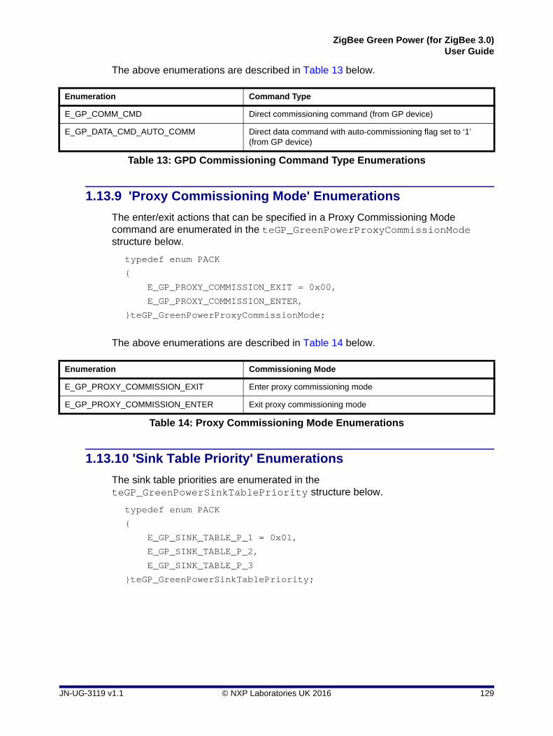
ZigBee Green Power (for ZigBee 3.0)User Guide
The above enumerations are described in Table 13 below.
1.13.9 'Proxy Commissioning Mode' Enumerations
The enter/exit actions that can be specified in a Proxy Commissioning Mode command are enumerated in the teGP_GreenPowerProxyCommissionMode structure below.
typedef enum PACK
{
E_GP_PROXY_COMMISSION_EXIT = 0x00,
E_GP_PROXY_COMMISSION_ENTER,
}teGP_GreenPowerProxyCommissionMode;
The above enumerations are described in Table 14 below.
1.13.10 'Sink Table Priority' Enumerations
The sink table priorities are enumerated in the teGP_GreenPowerSinkTablePriority structure below.
typedef enum PACK
{
E_GP_SINK_TABLE_P_1 = 0x01,
E_GP_SINK_TABLE_P_2,
E_GP_SINK_TABLE_P_3
}teGP_GreenPowerSinkTablePriority;
Enumeration Command Type
E_GP_COMM_CMD Direct commissioning command (from GP device)
E_GP_DATA_CMD_AUTO_COMM Direct data command with auto-commissioning flag set to ‘1’ (from GP device)
Table 13: GPD Commissioning Command Type Enumerations
Enumeration Commissioning Mode
E_GP_PROXY_COMMISSION_EXIT Enter proxy commissioning mode
E_GP_PROXY_COMMISSION_ENTER Exit proxy commissioning mode
Table 14: Proxy Commissioning Mode Enumerations
JN-UG-3119 v1.1 © NXP Laboratories UK 2016 129

Chapter 1Green Power Cluster
The above enumerations are described in Table 15 below.
1.13.11 ‘Translation Table Update Action’ Enumerations
The translation table update actions are enumerated in the teGP_TranslationTableUpdateAction structure below.
typedef enum PACK
{
E_GP_TRANSLATION_TABLE_ADD_ENTRY = 0x00,
E_GP_TRANSLATION_TABLE_REPLACE_ENTRY,
E_GP_TRANSLATION_TABLE_REMOVE_ENTRY
} teGP_TranslationTableUpdateAction;
The above enumerations are described in Table 16 below.
Enumeration Priority Description
E_GP_SINK_TABLE_P_1 Priority 1: Entry found in translation table
E_GP_SINK_TABLE_P_2 Priority 2: Entry not found in translation table but direct command received
E_GP_SINK_TABLE_P_3 Priority 3: Entry not found in translation table but tunnelled command received
Table 15: Sink Table Priority Enumerations
Enumeration Action
E_GP_TRANSLATION_TABLE_ADD_ENTRY Add a new translation in the table entry specified in the command. If the entry is already occupied, the action will be aborted. A specified entry index of 0xFF instructs the device to use any free entry in the translation table.
E_GP_TRANSLATION_TABLE_REPLACE_ENTRY Replace the translation in the specified table entry with the new translation.
E_GP_TRANSLATION_TABLE_REMOVE_ENTRY Delete the translation in the specified table entry.
Table 16: Translation Table Update Action Enumerations
130 © NXP Laboratories UK 2016 JN-UG-3119 v1.1

ZigBee Green Power (for ZigBee 3.0)User Guide
1.13.12 ‘Pairing Configuration Action’ Enumerations
The pairing configuration actions are enumerated in the teGP_GreenPowerPairingConfigAction structure below.
typedef enum
{
E_GP_PAIRING_CONFIG_NO_ACTION,
E_GP_PAIRING_CONFIG_EXTEND_SINK_TABLE_ENTRY,
E_GP_PAIRING_CONFIG_REPLACE_SINK_TABLE_ENTRY,
E_GP_PAIRING_CONFIG_REMOVE_SINK_TABLE_ENTRY,
E_GP_PAIRING_CONFIG_REMOVE_GPD
}teGP_GreenPowerPairingConfigAction;
The above enumerations are described in Table 16 below.
1.13.13 ‘Pairing Config Translation Table Action’ Enumerations
The pairing configuration translation table update actions are enumerated in the teGP_PairingConfigTranslationTableAction structure below.
typedef enum PACK
{
E_GP_PAIRING_CONFIG_TRANSLATION_TABLE_ADD_ENTRY = 0x00,
E_GP_PAIRING_CONFIG_TRANSLATION_TABLE_REMOVE_ENTRY,
E_GP_PAIRING_CONFIG_TRANSLATION_TABLE_EXTEND_ENTRY,
E_GP_PAIRING_CONFIG_TRANSLATION_TABLE_NO_ACTION
} teGP_PairingConfigTranslationTableAction;
Enumeration Action
E_GP_PAIRING_CONFIG_NO_ACTION None
E_GP_PAIRING_CONFIG_EXTEND_SINK_TABLE_ENTRY
Extend a sink table entry
E_GP_PAIRING_CONFIG_REPLACE_SINK_TABLE_ENTRY
Replace a sink table entry with a new pairing
E_GP_PAIRING_CONFIG_REMOVE_SINK_TABLE_ENTRY
Remove a sink table entry for a pairing
E_GP_PAIRING_CONFIG_REMOVE_GPD Remove a GP device from the sink table
Table 17: Pairing Configuration Action Enumerations
JN-UG-3119 v1.1 © NXP Laboratories UK 2016 131

Chapter 1Green Power Cluster
The above enumerations are described in Table 18 below.
1.13.14 ‘Reset-To-Default’ Enumerations
The ‘Reset-To-Default’ enumerations are used in a bitmap with the function vGP_RestorePersistedData() to indicate that whether attributes and sink/proxy tables need to be initialised to their defaults.
typedef enum
{
E_GP_DEFAULT_ATTRIBUTE_VALUE = 0x01,
E_GP_DEFAULT_PROXY_SINK_TABLE_VALUE = 0x02,
}teGP_ResetToDefaultConfig;
The above enumerations are described in Table 19 below.
Enumeration Action
E_GP_PAIRING_CONFIG_TRANSLATION_TABLE_ADD_ENTRY Add an entry to the translation table
E_GP_PAIRING_CONFIG_TRANSLATION_TABLE_REMOVE_ENTRY Remove an entry from the translation table
E_GP_PAIRING_CONFIG_TRANSLATION_TABLE_EXTEND_ENTRY Extend an existing entry in the transla-tion table
E_GP_PAIRING_CONFIG_TRANSLATION_TABLE_NO_ACTION Take no action on translation table
Table 18: Pairing Config Translation Table Action Enumerations
Enumeration Action
E_GP_DEFAULT_ATTRIBUTE_VALUE Sets bit to initialise attributes to their default values
E_GP_DEFAULT_PROXY_SINK_TABLE_VALUE Sets bit to initialise sink/proxy tables to their defaults
Table 19: Reset-To-Default Enumerations
132 © NXP Laboratories UK 2016 JN-UG-3119 v1.1

ZigBee Green Power (for ZigBee 3.0)User Guide
1.13.15 ‘Data Restore/Initialise’ Enumerations
The options for restoring from persisted data or initialising from default values are enumerated in the teGP_ResetToDefaultConfig structure below.
typedef enum
{
E_GP_DEFAULT_ATTRIBUTE_VALUE = 0x01,
E_GP_DEFAULT_PROXY_SINK_TABLE_VALUE = 0x02,
}teGP_ResetToDefaultConfig;
The above enumerations are described in Table 20 below.
Note that both the attributes and the sink/proxy table can be initialised to their default values by combining the above enumerations as follows:
E_GP_DEFAULT_ATTRIBUTE_VALUE | E_GP_DEFAULT_PROXY_SINK_TABLE_VALUE
1.13.16 ‘Security Level’ Enumerations
The security levels available for GP devices are enumerated in the teGP_GreenPowerSecLevel structure below.
typedef enum
{
E_GP_NO_SECURITY = 0x00,
E_GP_FULL_FC_FULL_MIC = 0x02,
E_GP_ENC_FULL_FC_FULL_MIC
}teGP_GreenPowerSecLevel;
The above enumerations are described in Table 21 below.
Enumeration Action
E_GP_DEFAULT_ATTRIBUTE_VALUE Attributes initialised to their default values and sink/proxy table restored with persisted values
E_GP_DEFAULT_PROXY_SINK_TABLE_VALUE Sink/proxy table initialised to default state and attributes restored with persisted values.
Table 20: Data Restore/Initialise Enumerations
Enumeration Action
E_GP_NO_SECURITY No security
E_GP_FULL_FC_FULL_MIC Full (4-byte) frame counter and full (4-byte) MIC only
E_GP_ENC_FULL_FC_FULL_MIC Encryption with full (4-byte) frame counter and full (4-byte) MIC
Table 21: Security Level Enumerations
JN-UG-3119 v1.1 © NXP Laboratories UK 2016 133

Chapter 1Green Power Cluster
1.13.17 ‘Security Key Type’ Enumerations
The security key types available for GP devices are enumerated in the teGP_GreenPowerSecKeyType structure below.
typedef enum
{
E_GP_NO_KEY = 0x00,
E_GP_ZIGBEE_NWK_KEY,
E_GP_ZGPD_GROUP_KEY,
E_GP_NWK_KEY_DERIVED_ZGPD_GROUP_KEY,
E_GP_OUT_OF_THE_BOX_ZGPD_KEY,
E_GP_DERIVED_INDIVIDUAL_ZGPD_KEY = 0x07
}teGP_GreenPowerSecKeyType;
The above enumerations are described in Table 22 below.
Enumeration Action
E_GP_NO_KEY No key
E_GP_ZIGBEE_NWK_KEY ZigBee network key
E_GP_ZGPD_GROUP_KEY Green Power group key programmed into all GP devices of group
E_GP_NWK_KEY_DERIVED_ZGPD_GROUP_KEY Green Power group key derived from network key
E_GP_OUT_OF_THE_BOX_ZGPD_KEY Individual 'out-of-the-box' GP device key
E_GP_DERIVED_INDIVIDUAL_ZGPD_KEY Individual GP device key derived from Green Power group key
Table 22: Security Key Types Enumerations
134 © NXP Laboratories UK 2016 JN-UG-3119 v1.1

ZigBee Green Power (for ZigBee 3.0)User Guide
1.14 Compile-Time Options
To incorporate the Green Power feature in the code to be built (for a sink or proxy node), it is necessary to add the following to the zcl_options.h file:
#define CLD_GREENPOWER
In addition, to include the software for a Combo Basic device or Proxy Basic device, it is necessary to add one of the following to the same file:
#define GP_COMBO_BASIC_DEVICE
#define GP_PROXY_BASIC_DEVICE
The following may also be defined in the zcl_options.h file.
Optional Attributes for Client
The optional attributes for the GP cluster client (see Section 1.3) are enabled by adding the following:
GPP Notification Retry Number attribute
#define CLD_GP_ATTR_ZGPP_NOTIFICATION_RETRY_NUMBER
GPP Notification Retry Timer attribute
#define CLD_GP_ATTR_ZGPP_NOTIFICATION_RETRY_TIMER
GPP Maximum Search Counter attribute
#define CLD_GP_ATTR_ZGPP_MAX_SEARCH_COUNTER
GPP Blocked GPD ID attribute
#define CLD_GP_ATTR_ZGPP_BLOCKED_GPD_ID
Optional Shared Attributes for Client and Server
The optional attributes that can be used on the GP cluster client and server (see Section 1.3) are enabled by adding the following:
GP Shared Security Key Type attribute
#define CLD_GP_ATTR_ZGP_SHARED_SECURITY_KEY_TYPE
GP Shared Security Key attribute
#define CLD_GP_ATTR_ZGP_SHARED_SECURITY_KEY
GP Link Key attribute
#define CLD_GP_ATTR_ZGP_LINK_KEY
JN-UG-3119 v1.1 © NXP Laboratories UK 2016 135

Chapter 1Green Power Cluster
Commissioning Window Attribute
The optional Commissioning Window attribute can be enabled as follows:
#define CLD_GP_ATTR_ZGPS_COMMISSIONING_WINDOW
Number of Sink/Proxy Table Entries
The maximum number of entries that can be stored in the sink/proxy table can be set to the value n as follows (default is 5):
#define GP_NUMBER_OF_PROXY_SINK_TABLE_ENTRIES n
Number of Unicast Sink List Entries
The maximum number of sink unicast addresses that can be stored in the proxy table entry for a GP device can be set to the value n as follows (default is 2):
#define GP_MAX_UNICAST_SINK n
Number of Sink Group List Entries
The maximum number of sink group addresses that can be stored in the proxy table entry for a GP device can be set to the value n as follows (default is 2):
#define GP_MAX_SINK_GROUP_LIST n
Number of Translation Table Entries
The maximum number of entries that can be stored in the Translation Table can be set to the value n as follows (default is 5):
#define GP_NUMBER_OF_TRANSLATION_TABLE_ENTRIES n
Number of Duplicate Table Entries
The maximum number of entries that can be stored in the duplicate table can be set to the value n as follows (default is 5):
#define GP_MAX_DUPLICATE_TABLE_ENTIRES n
Duplicate Table Entries Timeout
The maximum timeout, in seconds, of the entries stored in the duplicate table can be set to the value n as follows (default is 2):
#define GP_ZGP_DUPLICATE_TIMEOUT n
Commissioning Window Duration
The maximum duration of the commissioning window, in seconds, can be set to the value n as follows (default is 180):
#define GP_COMMISSION_WINDOW_DURATION n
136 © NXP Laboratories UK 2016 JN-UG-3119 v1.1

ZigBee Green Power (for ZigBee 3.0)User Guide
ZigBee Command Payload Length
When the Application ID is 0 (32-bit GP source address used), the maximum length of the ZigBee frame payload, in bytes, can be set to the value n as follows (default is 59):
#define GP_MAX_ZB_CMD_PAYLOAD_LENGTH n
When the Application ID is 2 (64-bit IEEE address used), the maximum length of the ZigBee frame payload, in bytes, can be set to the value n as follows (default is 27):
#define GP_MAX_ZB_CMD_PAYLOAD_LENGTH_APP_ID_2 n
Commissioning Command Payload Length
When the Application ID is 0 (32-bit GP source address used), the maximum length of a commissioning command payload, in bytes, can be set to the value n as follows (default is 55):
#define GP_MAX_ZB_COMM_CMD_PAYLOAD_LENGTH n
When the Application ID is 2 (64-bit IEEE address used), the maximum length of a commissioning command payload, in bytes, can be set to the value n as follows (default is 50):
#define GP_MAX_ZB_COMM_CMD_PAYLOAD_LENGTH_APP_ID_2 n
Maximum Number of Sink Entries in Sink Table Response
The maximum number of sink entries that can be handled in a Sink Table Response command can be set to the value n as follows (default is 70):
#define MAX_SINK_TABLE_ENTRIES_LENGTH n
Maximum Number of Proxy Entries in Proxy Table Response
The maximum number of proxy entries that can be handled in a Proxy Table Response command can be set to the value n as follows (default is 70):
#define MAX_PROXY_TABLE_ENTRIES_LENGTH n
Maximum Number of Translation Entries in Translation Table Response
The maximum number of translation entries that can be handled in a Translation Table Response command can be set to the value n as follows (default is 10):
#define GP_MAX_TRANSLATION_RESPONSE_ENTRY n
Maximum Number of Paired Endpoints
The maximum number of paired endpoints that can be handled in a Pairing Configuration command can be set to the value n as follows (default is 5):
#define GP_MAX_PAIRED_ENDPOINTS n
JN-UG-3119 v1.1 © NXP Laboratories UK 2016 137

Chapter 1Green Power Cluster
Timeout for GP Device Response
The maximum time to wait, in seconds, for a GPD Response can be set to the value n as follows (default is 5):
#define GP_MAX_PAIRED_ENDPOINTS n
Groupcast Radius
The groupcast radius for groupcast forwarding can be set to the value n as follows (default is 15):
#define GP_GROUPCAST_RADIUS n
IEEE Address Support for ZGPDs (GP devices)
IEEE address support for ZGPDs (GP devices) can be enabled as follows:
#define GP_IEEE_ADDR_SUPPORT
Disable Security for Certification/Testing
Security is enabled by default on a GP infrastructure device but can be disabled for network joining and transmitting/receiving unsecured packets during certification or testing as follows:
#define GP_DISABLE_SECURITY_FOR_CERTIFICATION
Optional Commands (Disable)
Optional commands can be disabled as follows:
Proxy Commissioning Mode command
#define GP_DISABLE_PROXY_COMMISSION_MODE_CMD
Commissioning Notification command
#define GP_DISABLE_COMMISSION_NOTIFICATION_CMD
Pairing Search command
#define GP_DISABLE_PAIRING_SEARCH_CMD
Translation Table Request command
#define GP_DISABLE_TRANSLATION_TABLE_REQ_CMD
Translation Table Response command
#define GP_DISABLE_TRANSLATION_TABLE_RSP_CMD
ZGP Response command
#define GP_DISABLE_ZGP_RESPONSE_CMD
138 © NXP Laboratories UK 2016 JN-UG-3119 v1.1

ZigBee Green Power (for ZigBee 3.0)User Guide
1.15 Green Power Terminology
The following key terminology is used in the description of ZigBee Green Power in this manual:
Term Description
Combo node A node which acts as both a sink node and proxy node.
Duplicate table A table on a sink or proxy node, containing a list of recently received GP commands, allowing duplicate received commands to be identified and discarded (see Section 1.4.1.4)
GP device A self-powered (energy harvesting or batteries) node which transmits a command in a (short) GP frame that is received by a proxy node in a ZigBee PRO network and is re-transmitted ‘tunnelled’ inside a ZigBee frame.
Proxy node A network node that can receive a GP frame from a source GP device and ‘tunnel’ this frame within a ZigBee frame, which is passed on to other network nodes.
Proxy table A table on a proxy node, containing a list of source GP devices which are in direct range and for which the local node acts as a proxy. A table entry stores pairing informa-tion about the GP device and the paired sink node.
Sink node A network node that is paired with a GP device and is the target for commands issued by the GP device.
Sink table A table on a sink or proxy node, containing the pairings of the local node with GP devices (see Section 1.4.1.2).
Translation table A table on a sink node, containing entries for GP devices and their associated GP commands, used to translate a received command into a command from the ZigBee application profile on the sink node (see Section 1.4.1.1).
Tunnelling The process of embedding a (GP) frame in the payload of a longer (ZigBee) frame.
ZGPD (ZigBee Green Power Device) A GP device (see above).
ZGPP (ZigBee Green Power Proxy) A GP proxy node (see above).
ZGPS (ZigBee Green Power Sink) A GP sink node (see above).
Table 23: Key Green Power Terms
JN-UG-3119 v1.1 © NXP Laboratories UK 2016 139

Chapter 1Green Power Cluster
140 © NXP Laboratories UK 2016 JN-UG-3119 v1.1

ZigBee Green Power (for ZigBee 3.0)User Guide
2. ZigBee PRO Stack Features for Green Power
This chapter describes the ZigBee PRO stack enhancements that support the ZigBee Green Power feature. These stack enhancements are provided in the NXP JN516x ZigBee 3.0 SDK (JN-SW-4170) and JN517x ZigBee 3.0 SDK (JN-SW-4270).
2.1 Stack Configuration
The ZigBee PRO stack must be configured to support the Green Power feature on a device that will be used as a GP proxy node or sink node. The initialisation required in the application on the node is outlined in Section 1.5 and includes enabling the GP feature in the ZigBee PRO stack, which is described in detail below.
This stack configuration is carried out in the ZPS Configuration Editor, which is described in the ZigBee 3.0 Stack User Guide (JN-UG-3113). The configuration must be done in two places in the editor:
Step 1 Enable Green Power support
a) In the ZPS Configuration Editor (within Eclipse), display the contents of the ZPS configuration file (.zpscfg file) for the application.
b) In the Properties tab in the bottom of the Eclipse window, click on Device Type and follow the path:
Device Type > Show Advanced Properties > Misc > Green Power Support
c) Set the value of Green Power Support to ‘true’.
Step 2 Create an endpoint for ZigBee Green Power
a) In the configuration tree displayed in the ZPS Configuration Editor, create the (reserved) endpoint 242 for the Green Power profile.
b) Set the Profile ID on this endpoint to 0xA1E0 (Green Power profile).
c) Save all the above changes.
2.2 Stack Events
Enabling the Green Power feature adds two stack events to those provided in the ZPS_teAfEventType structure of the ZigBee PRO stack software (detailed in the ZigBee 3.0 Stack User Guide (JN-UG-3113)). These additional stack events are as follows:
ZPS_EVENT_APS_ZGP_DATA_INDICATION
ZPS_EVENT_APS_ZGP_DATA_CONFIRM
These events are described below.
JN-UG-3119 v1.1 © NXP Laboratories UK 2016 141

Chapter 2ZigBee PRO Stack Features for Green Power
ZPS_EVENT_APS_ZGP_DATA_INDICATION
The ZPS_EVENT_APS_ZGP_DATA_INDICATION event is generated on a Green Power cluster server when a GP command has been received (either directly from the source node or indirectly via a proxy node). The event contains details of the received command in a ZPS_tsAfZgpDataIndEvent structure (see Section 2.3.1).
ZPS_EVENT_APS_ZGP_DATA_CONFIRM
The ZPS_EVENT_APS_ZGP_DATA_CONFIRM event is generated when a data confirmation command is transmitted from a GP sink node to a GP source node. This event needs to be passed into the vZCL_EventHandler() function by the application.
2.3 ZPS Structures
The structures detailed below are used for the stack events described in Section 2.2.
2.3.1 ZPS_tsAfZgpDataIndEvent
This structure is used in the ZPS_EVENT_APS_ZGP_DATA_INDICATION event, which indicates the arrival of GP command on the local node.
The ZPS_tsAfZgpDataIndEvent structure is detailed below.
typedef struct
{
ZPS_tuGpAddress uGpAddress;
PDUM_thAPduInstance hAPduInst;
uint32 u8Status :8;
uint32 u2ApplicationId :2;
uint32 u2SecurityLevel :2;
uint32 u2SecurityKeyType :2;
uint32 u8LinkQuality :8;
uint32 bAutoCommissioning :1;
uint32 bRxAfterTx :1;
uint32 u8CommandId :8;
uint32 u32Mic;
uint32 u32SecFrameCounter;
uint16 u16SrcPanId;
uint8 u8Rssi;
uint8 u8SrcAddrMode;
uint8 u8SeqNum;
uint8 u8FrameType;
uint8 u8Endpoint;
} ZPS_tsAfZgpDataIndEvent;
142 © NXP Laboratories UK 2016 JN-UG-3119 v1.1

ZigBee Green Power (for ZigBee 3.0)User Guide
The fields of the above structure are detailed in Table 1 below.
Field Type Valid Range Description
uGpAddress Unsigned 16-bit, 32-bit or 64-bit integer
16-bit, 32-bit or 64-bit value
Union containing an identifier of the GP device that sent GP command (as specified by u8SrcAddrMode) - one of:
• 64-bit IEEE/MAC address
• 16-bit network (short) address
• 32-bit source node identifier
hAPduInst -> u16Size Unsigned 8-bit integer
See description
The number of bytes in the received frame (cannot exceed aMaxMACFrameSize - 9)
hAPduInst -> au8Storage Set of bytes - The set of bytes forming the received frame
u8Status 8-bit enumeration
Any valid enumeration(see list)
Status code, returned by the GP stub. Can be any of the following:
• SECURITY_SUCCESS
• NO_SECURITY
• COUNTER_FAILURE
• AUTH_FAILURE
• UNPROCESSED
u2ApplicationId 8-bit enumeration
0x00, 0x02 Application ID, indicating the type of address used to identify the source node:
• 0x00: 32-bit GP source address
• 0x02: 64-bit IEEE/MAC address
u2SecurityLevel 8-bit enumeration
0x00 – 0x03 Security level of received GP command:
• 0x00: No security
• 0x01: 1-byte (LSB) of frame counter and short (2-byte) MIC
• 0x02: Full (4-byte) frame counter and full (4-byte) MIC
• 0x03: Encryption, full (4-byte) frame counter and full (4-byte) MIC
u2SecurityKeyType 8-bit enumeration
0x00 – 0x07 Security key type successfully used to pro-cess GP command:
• 0x00: No key
• 0x01: ZigBee network key
• 0x02: GPD group key
• 0x03: Network key derived from group key
• 0x04: Individual out-of-box GPD key
• 0x05: Reserved
• 0x06: Reserved
• 0x07: Individual derived GPD key
u8LinkQuality Unsigned 8-bit integer
0x00 – 0xFF The link quality for the received frame, as assessed by the IEEE 802.15.4 MAC layer
Table 1: ZPS_tsAfZgpDataIndEvent Fields
JN-UG-3119 v1.1 © NXP Laboratories UK 2016 143

Chapter 2ZigBee PRO Stack Features for Green Power
bAutoCommissioning Boolean 0x00, 0x01 Indicates whether the ‘auto-commissioning’ flag of the received command was set to ‘1’:
• 0x00 (FALSE): Flag not set
• 0x01 (TRUE): Flag set
bRxAfterTx Boolean 0x00, 0x01 Indicates whether the receiver on the source node (that sent the GP command) is on or off after a transmission:• 0x00 (FALSE): Receiver off after Tx• 0x01 (TRUE): Receiver on after Tx
u8CommandId Unsigned 8-bit integer
0x00 – 0xFF The identifier of the received GP command (within the GP specification) - for values, see Section 1.13.7.
u32Mic Unsigned 16-bit or 32-bit integer
2-byte or 4-byte value
Set of bytes (2 or 4, as specified in u2SecurityLevel) forming the MIC for the received GP command
u32SecFrameCounter Unsigned 32-bit Integer
1-byte or 4-byte value
A set of bytes (1 or 4, according to the value of u2SecurityLevel) containing the secu-rity frame counter value used on transmission of the GP command by the source node
u16SrcPanId 16-bit PAN ID
0x0000 – 0xFFFF
The 16-bit PAN ID of the source node entity from which the GP command was received
u8Rssi Unsigned 8-bit integer
0x00 – 0xFF RSSI (Received Signal Strength Indicator) level of received frame
u8SrcAddrMode 8-bit enumeration
0x00 – 0x03 The source addressing mode for this primitive corresponding to the received MPDU. This value can take one of the following values:0x00: No address (u16SrcPanId and uSrcAddress omitted)0x01: Reserved0x02: 16-bit short address0x03: 64-bit extended address
u8SeqNum Unsigned 8-bit integer
0x00 – 0xFF The sequence number from the MAC header of the received command
u8FrameType Unsigned 8-bit integer
0x00 – 0xFF The frame type, as follows:
• 0x00: Data frame
• 0x01: Maintenance frame
All other values are reserved.
u8Endpoint Unsigned 8-bit integer
0x00 – 0xFF Number of target endpoint for command
Table 1: ZPS_tsAfZgpDataIndEvent Fields
144 © NXP Laboratories UK 2016 JN-UG-3119 v1.1

ZigBee Green Power (for ZigBee 3.0)User Guide
2.3.2 ZPS_tsAfZgpDataConfEvent
This structure is used in the ZPS_EVENT_APS_ZGP_DATA_CONFIRM event, which indicates that a data confirmation has been returned to the GP source node (that previously sent some data).
The ZPS_tsAfZgpDataConfEvent structure is detailed below.
typedef struct {
uint8 u8Status;
uint8 u8Handle;
} ZPS_tsAfZgpDataConfEvent;
The fields of the above structure are detailed in Table 2 below.
2.3.3 ZPS_tuGpAddress
This union structure contains the address details of a GP device.
typedef union {
uint64 u64Addr;
uint32 u32SrcId;
uint16 u16Addr;
} ZPS_tuGpAddress;
where:
u64Addr is the 64-bit IEEE/MAC address of the GP device
u32SrcId is the 32-bit Source ID of the GP device
u16Addr is the 16-bit network address of the GP device
Field Type Valid Range Description
u8Status Enumeration Any valid enumeration(see list)
Status code, returned by the GP stub. Can be any of the following:
• TX_QUEUE_FULL
• ENTRY_REPLACED
• ENTRY_ADDED
• ENTRY_EXPIRED
• ENTRY_REMOVED
• GPDF_SENDING_FINALIZED
u8Handle Unsigned 8-bit integer 0x00 – 0xFF The handle used between the proxy endpoint (EPP) and the lower stack layers to match the request with the confirmation
Table 2: ZPS_tsAfZgpDataConfEvent Fields
JN-UG-3119 v1.1 © NXP Laboratories UK 2016 145

Chapter 2ZigBee PRO Stack Features for Green Power
2.3.4 ZPS_tuAfZgpGreenPowerId
This union structure contains the address details of a GP device.
typedef union
{
uint64 u64Address;
uint32 u32SrcId;
}ZPS_tuAfZgpGreenPowerId;
where:
u64Addr is the 64-bit IEEE/MAC address of the GP device
u32SrcId is the 32-bit Source ID of the GP device
2.3.5 ZPS_tsAfZgpGreenPowerReq
This structure contains the details of a GP command, such as a GP Channel Request, sent by a GP device.
typedef struct
{
ZPS_tuAfZgpGreenPowerId uGpId;
uint16 u16Panid;
uint16 u16DstAddr;
uint16 u16TxQueueEntryLifetime;
uint8 u8Handle;
uint8 u8ApplicationId;
uint8 u8SeqNum;
uint8 u8TxOptions;
uint8 u8Endpoint;
// bool_t bDataFrame;
}ZPS_tsAfZgpGreenPowerReq;
where:
uGpId is a union containing an identifier of the source GP device of the command (see Section 2.3.3) - the type of identifier is specified in u8ApplicationId.
u16Panid is the PAN ID of the target network for the command.
u16DstAddr is the 16-bit network address of the target sink node.
u16TxQueueEntryLifetime is the maximum length of time, in milliseconds, that the command should remain in the transmit queue on the GP device. The value 0x0000 indicates that the transmission must be immediate and 0xFFFF indicates an indefinite queuing time.
u8Handle is a handle for the command.
146 © NXP Laboratories UK 2016 JN-UG-3119 v1.1

ZigBee Green Power (for ZigBee 3.0)User Guide
u8ApplicationId is a value indicating the type of identifier used in uGpId to specify the source GP device:
0x00: Source ID
0x02: IEEE/MAC address
u8SeqNum is the sequence number used to match the response with the request.
u8TxOptions is a bitmap indicating the transmission options for the request:
u8Endpoint is the number of the target endpoint (on the target sink node) for the request
2.3.6 ZPS_tsAfZgpTxGpQueue
This structure contains the transmit queue on a GP device.
typedef struct
{
ZPS_tsAfZgpTxGpQueueEntry* psTxQTable;
uint8 u8Size;
}ZPS_tsAfZgpTxGpQueue;
where:
psTxQTable is a pointer to the set of transmit queue entries, where each entry is a ZPS_tsAfZgpTxGpQueueEntry structure (see Section 2.3.7).
u8Size is the number of entries in the transmit queue.
Bits Description
0 Enables/disables use of the transmit queue on the source GP device:1: Use transmit queue0: Do not use transmit queue
1 Enables/disables use of CSMA/CA during transmission:1: Use CSMA/CA 0: Do not use CSMA/CA
2 Enables/disables use of IEEE802.15.4 MAC acknowledgements:1: Use MAC acks0: Do not use MAC acks
3-4 Indicates the type of frame used:00: Data frame01: Maintenance frameOther values are reserved.
5-7 Reserved
JN-UG-3119 v1.1 © NXP Laboratories UK 2016 147

Chapter 2ZigBee PRO Stack Features for Green Power
2.3.7 ZPS_tsAfZgpTxGpQueueEntry
This structure contains an entry for a GP command in the transmit queue on a GP device.
typedef struct
{
ZPS_tsAfZgpGreenPowerReq sReq;
PDUM_thNPdu hNPdu;
bool_t bValid;
}ZPS_tsAfZgpTxGpQueueEntry;
where:
sReq is a structure containing the details of the GP command contained in the entry, as described in Section 2.3.5.
hNPdu is the handle of the NPDU allocated to the queue entry.
bValid is a Boolean indicating whether the entry is valid (TRUE) or invalid (FALSE).
2.3.8 ZPS_tsAfZgpGpst
This structure contains the security table of a GP device.
typedef struct
{
ZPS_tsAfZgpGpstEntry* psGpSecTable;
uint8 u8Size;
}ZPS_tsAfZgpGpst;
where:
psGpSecTable is a pointer to a set of security table entries, where each entry is a ZPS_tsAfZgpGpstEntry structure (see Section 2.3.9).
u8Size is the number of entries in the security table.
148 © NXP Laboratories UK 2016 JN-UG-3119 v1.1

ZigBee Green Power (for ZigBee 3.0)User Guide
2.3.9 ZPS_tsAfZgpGpstEntry
This structure contains an entry of the security table of a GP device.
typedef struct
{
AESSW_Block_u uSecurityKey;
ZPS_tuAfZgpGreenPowerId uGpId;
uint32 u32Counter;
uint8 u8SecurityLevel;
uint8 u8KeyType;
bool_t bValid;
} ZPS_tsAfZgpGpstEntry;
where:
uSecurityKey is the AES encryption key used by the GP device.
uGpId is a union containing an identifier of the GP device (see Section 2.3.3).
u32Counter is a 32-bit security frame counter for the GP device (if used).
u8SecurityLevel is the security level used by the GP device:
0x00: No security
0x01: Reserved
0x02: Full (4-byte) frame counter and full (4-byte) MIC only
0x03: Encryption with full (4-byte) frame counter and full (4-byte) MIC
0x04-0x07: Reserved
u8KeyType is the security key type used by the GP device:
0x00: No key
0x01: ZigBee network key
0x02: GPD group key
0x03: Network key derived from GPD group key
0x04: Individual out-of-box GPD key
0x05-0x06: Reserved
0x07: Individual derived GPD key
bValid is a Boolean indicating whether the entry is used:
TRUE: Used
FALSE: Unused
JN-UG-3119 v1.1 © NXP Laboratories UK 2016 149

Chapter 2ZigBee PRO Stack Features for Green Power
2.3.10 ZPS_tsAfZgpSecReq
This structure contains the security details of the GP device.
typedef struct
{
ZPS_tuAfZgpGreenPowerId uGpId;
uint32 u32FrameCounter;
uint32 u32Mic;
uint8 u8SecurityLevel;
uint8 u8KeyType;
uint8 u8ApplicationId;
uint8 u8Endpoint;
}ZPS_tsAfZgpSecReq;
where:
uGpId is a union containing an identifier of the GP device (see Section 2.3.3).
u32FrameCounter is a 32-bit security frame counter for the GP device (if used).
u32Mic is a set of four bytes forming the MIC.
u8SecurityLevel is the security level used by the GP device:
0x00: No security
0x01: Reserved
0x02: Full (4-byte) frame counter and full (4-byte) MIC only
0x03: Encryption with full (4-byte) frame counter and full (4-byte) MIC
0x04-0x07: Reserved
u8KeyType is the security key type used by the GP device:
0x00: No key
0x01: ZigBee network key
0x02: GPD group key
0x03: Network key derived from GPD group key
0x04: Individual out-of-box GPD key
0x05-0x06: Reserved
0x07: Individual derived GPD key
u8ApplicationId is a value indicating the type of identifier used in uGpId to specify the source GP device:
0x00: Source ID
0x02: IEEE/MAC address
u8Endpoint is the number of the endpoint on the corresponding sink node.
150 © NXP Laboratories UK 2016 JN-UG-3119 v1.1

ZigBee Green Power (for ZigBee 3.0)User Guide
2.3.11 ZPS_tsAfZgpGreenPowerContext
This structure contains the context data that is saved to non-volatile memory on a GP device.
typedef struct
{
ZPS_tsAfZgpGpst *psGpst;
ZPS_tsAfZgpTxGpQueue *psTxQueue;
ZPS_tsTsvTimer *psTxAgingTimer;
TSV_Timer_s *psTxBiDirTimer;
uint16 u16MsecInterval;
uint8 u8TxPoint;
}ZPS_tsAfZgpGreenPowerContext;
where:
psGpst is a pointer to the security table of the GP device, contained in a ZPS_tsAfZgpGpst structure (see Section 2.3.8).
psTxQueue is a pointer to the transmit queue, contained in a ZPS_tsAfZgpTxGpQueue structure (see Section 2.3.6).
psTxAgingTimer is a pointer to a structure containing details of a software timer used for aging entries in the transmit queue.
psTxBiDirTimer is a pointer to a structure containing details of a software timer used in bi-directional commissioning mode.
u16MsecInterval is the time-interval, in milliseconds, with which the device will periodically attempt to age data.
u8TxPoint is the location in the transmit queue of the next frame to be transmitted.
JN-UG-3119 v1.1 © NXP Laboratories UK 2016 151

Chapter 2ZigBee PRO Stack Features for Green Power
152 © NXP Laboratories UK 2016 JN-UG-3119 v1.1

ZigBee Green Power (for ZigBee 3.0)User Guide
3. MicroMAC Stack for Green Power
A Green Power source node does not require any ZigBee software components, as the Green Power frames that it transmits are simple IEEE 802.15.4 frames (rather than ZigBee-format frames). Therefore, the software required by a source node is an application and the IEEE 802.15.4 stack.
A special version of the IEEE 802.15.4 stack can be employed in which the MAC layer is replaced with an NXP-adapted ‘MicroMAC’ layer in order to minimise the energy required for frame transmissions (particularly useful for energy-harvesting nodes) and to reduce application code size.
This chapter describes the NXP MicroMAC software, which comprises the MicroMAC stack and the MicroMAC Application Programming Interface (API) containing C functions for use in application development. This software is provided in the JN516x ZigBee 3.0 SDK (JN-SW-4170) and JN517x ZigBee 3.0 SDK (JN-SW-4270).
3.1 Enabling the MicroMAC
In order to use the MicroMAC stack, it must be enabled for the application on the source node as follows:
In the application’s makefile, add the MicroMAC library in the ‘Additional libraries’ section, as shown below:
# Application libraries
# Specify additional Component libraries
APPLIBS += MMAC
Also in the makefile, set the stack parameter as follows:
JENNIC_STACK = None
In the application code, reference the header file MMAC.h, as shown below:
#include "MMAC.h"
In the application code, call vMMAC_Enable() as the first MicroMAC API function (see Section 3.2.1 and Section 3.3.1)
3.2 Application Coding for the MicroMAC
This section describes the function calls that are required in an application in order to use the MicroMAC to transmit and receive frames. The descriptions are organised in the following sub-sections:
Initialisation - see Section 3.2.1
Transmitting frames - see Section 3.2.2
Receiving frames - see Section 3.3.3
The referenced MicroMAC API functions are fully detailed in Section 3.3.
JN-UG-3119 v1.1 © NXP Laboratories UK 2016 153

Chapter 3MicroMAC Stack for Green Power
3.2.1 Initialisation
In order to initialise the MicroMAC, the first function that must be called is vMMAC_Enable(). This function enables the MAC hardware block on the JN516x/7x device.
Next, MicroMAC interrupts should be enabled using the function vMMAC_EnableInterrupts(). This will allow interrupts to be generated to inform the application when frames have been transmitted and/or received. The above function requires a user-defined interrupt handler function to be specified, which will be automatically invoked when a MicroMAC interrupt occurs. For the prototype of this interrupt handler, refer to the description of vMMAC_EnableInterrupts() on page 159.
The radio transceiver of the JN516x/7x device must then be set up by calling two functions:
vMMAC_ConfigureRadio() must first be called to configure and calibrate the radio transceiver
vMMAC_SetChannel() must then be called to select the IEEE 802.15.4 2.4-GHz channel on which the transceiver will operate (in the range 11-26)
The JN516x/7x device is then ready to transmit and receive frames, as described in Section 3.2.2 and Section 3.2.3.
The above functions are fully detailed in Section 3.3.1.
3.2.2 Transmitting Frames
A frame can be transmitted using the function vMMAC_StartMacTransmit(). When calling this function, a number of options are available and all these options require pre-configuration (before the above transmit function is called).
The transmit options and the necessary pre-configuration are as follows:
Delayed transmission
This option allows the transmission to be delayed until a certain ‘time’. This time is represented by a value of the free-running 62500-Hz internal clock. Use of this feature requires the following pre-configuration:
a) The timing function u32MMAC_GetTime() must first be called to obtain the current value of the internal clock.
b) The function vMMAC_SetTxStartTime() must then be immediately called to specify the ‘time’ at which the next transmission should occur. This ‘time’ should be calculated by adding the ‘current time’ (obtained above) to the required delay (as a number of clock cycles).
Automatic acknowledgements
This option requests the transmitted frame to be acknowledged by the recipient. If no acknowledgement is received, the frame will be re-transmitted. Use of this feature requires pre-configuration by calling the vMMAC_SetTxParameters() function, in which the number of attempts to transmit a frame without an acknowledgement must be specified.
154 © NXP Laboratories UK 2016 JN-UG-3119 v1.1
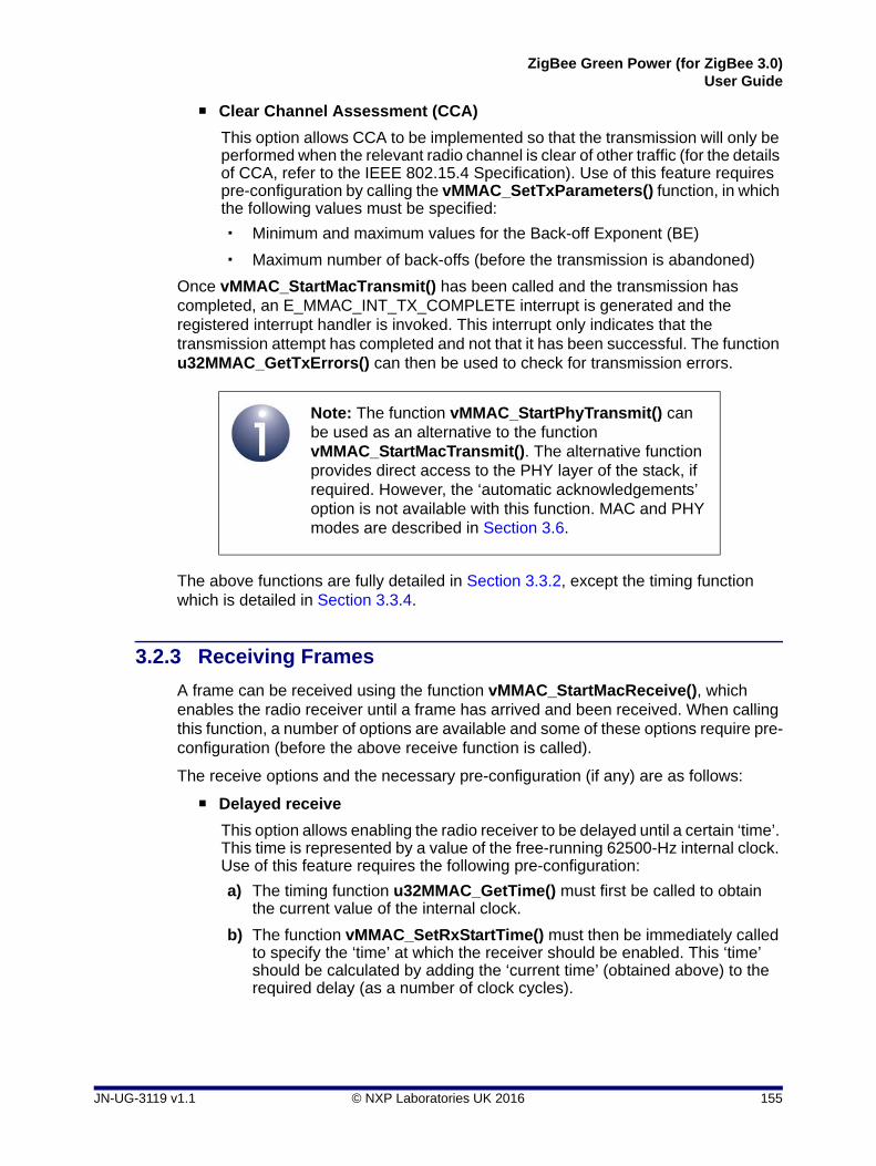
ZigBee Green Power (for ZigBee 3.0)User Guide
Clear Channel Assessment (CCA)
This option allows CCA to be implemented so that the transmission will only be performed when the relevant radio channel is clear of other traffic (for the details of CCA, refer to the IEEE 802.15.4 Specification). Use of this feature requires pre-configuration by calling the vMMAC_SetTxParameters() function, in which the following values must be specified:
Minimum and maximum values for the Back-off Exponent (BE)
Maximum number of back-offs (before the transmission is abandoned)
Once vMMAC_StartMacTransmit() has been called and the transmission has completed, an E_MMAC_INT_TX_COMPLETE interrupt is generated and the registered interrupt handler is invoked. This interrupt only indicates that the transmission attempt has completed and not that it has been successful. The function u32MMAC_GetTxErrors() can then be used to check for transmission errors.
The above functions are fully detailed in Section 3.3.2, except the timing function which is detailed in Section 3.3.4.
3.2.3 Receiving Frames
A frame can be received using the function vMMAC_StartMacReceive(), which enables the radio receiver until a frame has arrived and been received. When calling this function, a number of options are available and some of these options require pre-configuration (before the above receive function is called).
The receive options and the necessary pre-configuration (if any) are as follows:
Delayed receive
This option allows enabling the radio receiver to be delayed until a certain ‘time’. This time is represented by a value of the free-running 62500-Hz internal clock. Use of this feature requires the following pre-configuration:
a) The timing function u32MMAC_GetTime() must first be called to obtain the current value of the internal clock.
b) The function vMMAC_SetRxStartTime() must then be immediately called to specify the ‘time’ at which the receiver should be enabled. This ‘time’ should be calculated by adding the ‘current time’ (obtained above) to the required delay (as a number of clock cycles).
Note: The function vMMAC_StartPhyTransmit() can be used as an alternative to the function vMMAC_StartMacTransmit(). The alternative function provides direct access to the PHY layer of the stack, if required. However, the ‘automatic acknowledgements’ option is not available with this function. MAC and PHY modes are described in Section 3.6.
JN-UG-3119 v1.1 © NXP Laboratories UK 2016 155

Chapter 3MicroMAC Stack for Green Power
Automatic acknowledgements
This option allows automatic acknowledgements to be sent. If this option is enabled and an acknowledgement has been requested for a received frame, the stack will automatically return an acknowledgement to the sender of the frame.
Malformed frames
This option allows the rejection of received frames that appear to be malformed.
Frame Check Sequence (FCS) errors
This option allows the rejection of received frames that have FCS errors.
Address matching
This option allows the rejection of frames that do not contain the destination identifer values of the local node. These local node identifers must be pre-configured using the function vMMAC_SetRxAddress() and are as follows:
PAN ID of the network to which the local node belongs
16-bit short address of the local node
64-bit IEEE/MAC (extended) address of the local node
Once vMMAC_StartMacReceive() has been called and the receive has completed, the receiver is disabled and two interrupts are generated, with the registered interrupt handler invoked separately for each one:
E_MMAC_INT_RX_HEADER signals the reception of the MAC header of the frame (but the interrupt is generated after receiving the whole frame)
E_MMAC_INT_RX_COMPLETE signals the reception of the whole frame (but is generated after an acknowedgement has been sent, if requested/enabled)
These interrupts only indicate that the receive attempt has completed and not that it has been successful. The function u32MMAC_GetRxErrors() can then be used to check for receive errors.
The above functions are fully detailed in Section 3.3.3, except the timing function which is detailed in Section 3.3.4.
Note: The function vMMAC_StartPhyReceive() can be used as an alternative to the function vMMAC_StartMacReceive(). The alternative function provides direct access to the PHY layer of the stack, if required. However, the ‘automatic acknowledgements’, ‘malformed frames’ and ‘address matching’ options are not available with this function. MAC and PHY modes are described in Section 3.6.
156 © NXP Laboratories UK 2016 JN-UG-3119 v1.1

ZigBee Green Power (for ZigBee 3.0)User Guide
3.3 MicroMAC API
The MicroMAC library includes an API, comprising C functions for use by the application. These functions are divided into the following categories and detailed in the referenced sub-sections:
Initialisation functions - see Section 3.3.1
Transmit functions - see Section 3.3.2
Receive functions - see Section 3.3.3
Timing function - see Section 3.3.4
Note that the MicroMAC API is intentionally small and simple, in order to minimise the application size and also to minimise the run-time when used in energy-harvesting applications. Hence, the API functions do not carry out error checking or range checking on the values passed to them.
3.3.1 Initialisation Functions
The following Initialisation functions are provided in the MicroMAC API.
Function Page
vMMAC_Enable 158
vMMAC_EnableInterrupts 159
vMMAC_ConfigureRadio 160
vMMAC_SetChannel 161
All of the above functions must be called by the application, starting with the function vMMAC_Enable(). They should be called in the order that they are listed above.
JN-UG-3119 v1.1 © NXP Laboratories UK 2016 157

Chapter 3MicroMAC Stack for Green Power
vMMAC_Enable
Description
This function enables the MAC hardware block and must be called before using any other MicroMAC functions.
After calling this function, the other MicroMAC Intialisation functions (described in this section) should be called.
Parameters
None
Returns
None
void vMMAC_Enable(void);
158 © NXP Laboratories UK 2016 JN-UG-3119 v1.1

ZigBee Green Power (for ZigBee 3.0)User Guide
vMMAC_EnableInterrupts
Description
This function enables transmit and receive interrupts, and allows the application to register a user-defined callback function that will be invoked when a MicroMAC interrupt is generated.
The uint32 value returned to the interrupt handler is a bitmap that indicates the nature of the MicroMAC interrupt. This value can be logical-ORed with the following enumerated values from teIntStatus to determine the type of interrupt:
E_MMAC_INT_TX_COMPLETE (0x01)
E_MMAC_INT_RX_HEADER (0x02)
E_MMAC_INT_RX_COMPLETE (0x04)
For more information on these interrupt types, refer to Section 3.5.5.
Parameters
prHandler Pointer to the MicroMAC interrupt handler callback function
Returns
None
void vMMAC_EnableInterrupts(void (*prHandler)(uint32));
JN-UG-3119 v1.1 © NXP Laboratories UK 2016 159

Chapter 3MicroMAC Stack for Green Power
vMMAC_ConfigureRadio
Description
This function configures and calibrates the radio transceiver on the JN516x/7x device. It must be called before setting the channel (using vMMAC_SetChannel()) and before attempting to transmit or receive (using the functions detailed in Section 3.3.2 and Section 3.3.3).
Parameters
None
Returns
None
void vMMAC_ConfigureRadio(void);
160 © NXP Laboratories UK 2016 JN-UG-3119 v1.1

ZigBee Green Power (for ZigBee 3.0)User Guide
vMMAC_SetChannel
Description
This function sets the radio channel to be used by the radio transceiver. The required 2.4-GHz channel number in the range 11 to 26 must be specified.
The function must be called after the radio transceiver has been configured (using vMMAC_ConfigureRadio()).
Parameters
u8Channel Required channel number in the range 11 to 26 (other values are not valid)
Returns
None
void vMMAC_SetChannel(uint8 u8Channel);
JN-UG-3119 v1.1 © NXP Laboratories UK 2016 161
Chapter 3MicroMAC Stack for Green Power
3.3.2 Transmit Functions
The following Transmit functions are provided in the MicroMAC API.
Function Page
vMMAC_SetTxParameters 163
vMMAC_SetTxStartTime 164
vMMAC_StartMacTransmit 165
vMMAC_StartPhyTransmit 166
u32MMAC_GetTxErrors 167
162 © NXP Laboratories UK 2016 JN-UG-3119 v1.1

ZigBee Green Power (for ZigBee 3.0)User Guide
vMMAC_SetTxParameters
Description
This function sets a number of transmit parameters in connection with ‘automatic acknowledgements’ and Clear Channel Assessment (CCA). These two features can be enabled for an individual ‘MAC mode’ transmission when the transmit function vMMAC_StartMacTransmit() is called. CCA can also be enabled for a ‘PHY mode’ transmission when the transmit function vMMAC_StartPhyTransmit() is called.
When transmitting with automatic acknowledgements enabled, the transmitted frame must be acknowledged by the recipient. If no acknowledgement is received, the frame will be re-transmitted. The number of attempts to transmit a frame without an acknowledgement can be specified through the parameter u8Attempts.
The other three parameters are related to CCA (when enabled):
Minimum and maximum values for the Back-off Exponent (BE) are specified through the parameters u8MinBE and u8MaxBE, respectively
The maximum number of back-offs (before the transmission is abandoned) is specified through the parameter u8MaxBackoffs
For the details of CCA, refer to the IEEE 802.15.4 Specification. The above three function parameters correspond to the PIB attributes macMinBE, macMaxBE and macMaxCSMABackoffs, respectively, in the specification.
Parameters
u8Attempts Maximum number of transmission attempts without receiving an acknowledgement
u8MinBE Minimum value of Back-off Exponent to be used in CCA
u8MaxBE Maximum value of Back-off Exponent to be used in CCA
u8MaxBackoffs Maximum number of back-offs in CCA
Returns
None
void vMMAC_SetTxParameters(uint8 u8Attempts, uint8 u8MinBE, uint8 u8MaxBE, uint8 u8MaxBackoffs);
Note 1: The vMMAC_SetTxParameters function only needs to be called once on every cold or warm start - it does not need to be called for each transmit operation.
Note 2: The function does not need to be called if you are not going to use CCA or automatic acknowledgements (selected as options when calling the relevant transmit function).
JN-UG-3119 v1.1 © NXP Laboratories UK 2016 163

Chapter 3MicroMAC Stack for Green Power
vMMAC_SetTxStartTime
Description
This function sets the ‘time’ at which a transmission should begin. This time is specified as a value of the free-running 62500-Hz internal clock.
Before calling this function, the u32MMAC_GetTime() function should be called to obtain the current value of the clock. The application should then determine the required clock value to be specified in vMMAC_SetTxStartTime() in order to start the next transmission at the desired time.
If used, this function must be called before the relevant transmit function (vMMAC_StartMacTransmit() or vMMAC_StartPhyTransmit()), and a ‘delayed transmission’ must be enabled in the options specified in the transmit function. The transmitter will then be enabled and the transmission will be performed when the internal clock value matches the value specified in this function.
Parameters
u32Time Internal clock value at which transmission should begin
Returns
None
void vMMAC_SetTxStartTime(uint32 u32Time);
Note: This function only needs to be called if you are going to use the ‘delayed transmission’ feature (selected as an option when calling the relevant transmit function).
164 © NXP Laboratories UK 2016 JN-UG-3119 v1.1

ZigBee Green Power (for ZigBee 3.0)User Guide
vMMAC_StartMacTransmit
Description
This function starts the transmitter in ‘MAC mode’, with the specified options, in order to transmit a frame. A pointer must be provided to the frame to be transmitted.
The MAC mode options relate to three features and are specified as enumerations:
Enumerations for the three features must be combined in a logical-OR operation.
Note the following:
If the ‘delayed transmission’ option is enabled, this feature should be pre-configured using the function vMMAC_SetTxStartTime().
If the automatic acknowledgements and/or CCA options are enabled, these features should be pre-configured using the function vMMAC_SetTxParameters().
If interrupts have been enabled using vMMAC_EnableInterrupts(), an interrupt (E_MMAC_INT_TX_COMPLETE) will be generated once the transmission attempt has completed.
Parameters
psFrame Pointer to a pre-filled structure containing the frame to be transmitted (see Section 3.4.1)
eOptions Value indicating the required features for this transmission (see above and Section 3.5.1)
Returns
None
void vMMAC_StartMacTransmit(tsMacFrame *psFrame, teTxOption eOptions);
Feature Enumeration Description
Delayed transmission E_MMAC_TX_START_NOW Start transmission as soon as this function is called
E_MMAC_TX_DELAY_START Start transmission at the time specified beforehand using vMMAC_SetTxStartTime()
Automatic acknowledgements and re-try
E_MMAC_TX_NO_AUTO_ACK Do not enable automatic acknowledgements and re-try
E_MMAC_TX_USE_AUTO_ACK Enable automatic acknowl-edgements and re-try
Clear Channel Assessment (CCA)
E_MMAC_TX_NO_CCA Do not enable CCA
E_MMAC_TX_USE_CCA Enable CCA
JN-UG-3119 v1.1 © NXP Laboratories UK 2016 165

Chapter 3MicroMAC Stack for Green Power
vMMAC_StartPhyTransmit
Description
This function starts the transmitter in ‘PHY mode’, with the specified options, in order to transmit a frame. A pointer must be provided to the frame to be transmitted.
The PHY mode options relate to two features and are specified as enumerations:
Enumerations for the two features must be combined in a logical-OR operation.
Note the following:
If the ‘delayed transmission’ option is enabled, this feature should be pre-configured using the function vMMAC_SetTxStartTime().
If the CCA option is enabled, this feature should be pre-configured using the function vMMAC_SetTxParameters().
If interrupts have been enabled using vMMAC_EnableInterrupts(), an interrupt (E_MMAC_INT_TX_COMPLETE) will be generated once the transmission attempt has completed.
Parameters
psFrame Pointer to a pre-filled structure containing the frame to be transmitted (see Section 3.4.2)
eOptions Value indicating the required features for this transmission (see above and Section 3.5.1)
Returns
None
void vMMAC_StartPhyTransmit(tsPhyFrame *psFrame, teTxOption eOptions);
Note: This function provides direct access to the PHY layer of the stack. If you do not need this access, you should use the function vMMAC_StartMacTransmit() to transmit a frame.
Feature Enumeration Description
Delayed transmission E_MMAC_TX_START_NOW Start transmission as soon as this function is called
E_MMAC_TX_DELAY_START Start transmission at the time specified beforehand using vMMAC_SetTxStartTime()
Clear Channel Assessment (CCA)
E_MMAC_TX_NO_CCA Do not enable CCA
E_MMAC_TX_USE_CCA Enable CCA
166 © NXP Laboratories UK 2016 JN-UG-3119 v1.1

ZigBee Green Power (for ZigBee 3.0)User Guide
u32MMAC_GetTxErrors
Description
This function can be used to report any errors that have occurred during a frame transmission. It should only be called after the transmission has completed (indicated by an interrupt, if enabled).
The returned value is a bitmap that can be logical-ORed with the following enumerated values from teTxStatus to determine the error condition(s):
E_MMAC_TXSTAT_CCA_BUSY (0x01)
E_MMAC_TXSTAT_NO_ACK (0x02)
E_MMAC_TXSTAT_ABORTED (0x04)
A returned value of 0 indicates no error.
For more information on the above error conditions, refer to Section 3.5.2.
Parameters
None
Returns
32-bit bitmap indicating the errors that have occurred (see above)
uint32 u32MMAC_GetTxErrors(void);
JN-UG-3119 v1.1 © NXP Laboratories UK 2016 167

Chapter 3MicroMAC Stack for Green Power
3.3.3 Receive Functions
The following Receive functions are provided in the MicroMAC API.
Function Page
vMMAC_SetRxAddress 169
vMMAC_SetRxStartTime 170
vMMAC_StartMacReceive 171
vMMAC_StartPhyReceive 173
u32MMAC_GetRxErrors 174
168 © NXP Laboratories UK 2016 JN-UG-3119 v1.1

ZigBee Green Power (for ZigBee 3.0)User Guide
vMMAC_SetRxAddress
Description
This function configures settings for receiving frames when ‘address matching’ is enabled. Address matching can be enabled for ‘MAC mode’ when the receive function vMMAC_StartMacReceive() is called, but is not available for ‘PHY mode’.
The function specifies the following values for this purpose:
PAN ID of the network to which the local node belongs
16-bit short address of the local node
64-bit IEEE/MAC (extended) address of the local node
Only received frames with destination parameters that match the values supplied to this function will be accepted.
Parameters
u16PanId 16-bit PAN ID of network to which local node belongs
u16Short 16-bit short address of local node
psMacAddr Pointer to a structure containing 64-bit IEEE/MAC address of local node (see Section 3.4.4)
Returns
None
void vMMAC_SetRxAddress(uint16 u16PanId, uint16 u16Short, MAC_ExtAddr_s *psMacAddr);
Note 1: The vMMAC_SetRxAddress() function only needs to be called once on every cold or warm start - it does not need to be called for each receive operation.
Note 2: If receiving with address matching disabled or using ‘PHY mode’, the supplied values are ignored and so this function call is unnecessary.
JN-UG-3119 v1.1 © NXP Laboratories UK 2016 169

Chapter 3MicroMAC Stack for Green Power
vMMAC_SetRxStartTime
Description
This function sets the ‘time’ at which the receiver should be enabled. This time is specified as a value of the free-running 62500-Hz internal clock.
Before calling this function, the u32MMAC_GetTime() function should be called to obtain the current value of the clock. The application should then determine the required clock value to be specified in vMMAC_SetRxStartTime() in order to start the receiver at the desired time.
If used, this function must be called before the relevant receive function (vMMAC_StartMacReceive() or vMMAC_StartPhyReceive()), and a ‘delayed receive’ must be enabled in the options specified in the receive function. The receiver will then be enabled when the internal clock value matches the value specified in this function.
Parameters
u32Time Internal clock value at which receiver should be enabled
Returns
None
void vMMAC_SetRxStartTime(uint32 u32Time);
Note: This function only needs to be called if you are going to use the ‘delayed receive’ feature (selected as an option when calling the relevant receive function).
170 © NXP Laboratories UK 2016 JN-UG-3119 v1.1

ZigBee Green Power (for ZigBee 3.0)User Guide
vMMAC_StartMacReceive
Description
This function starts the receiver in ‘MAC mode’, with the specified options, in order to receive a frame. A pointer must be provided to a structure to which the received frame will be written.
The MAC mode options relate to five features and are specified as enumerations:
Enumerations for the five features must be combined in a logical-OR operation.
void vMMAC_StartMacReceive(tsMacFrame *psFrame, teRxOption eOptions);
Feature Enumeration Description
Delayed receive E_MMAC_RX_START_NOW Start receiver as soon as this function is called
E_MMAC_RX_DELAY_START Start receiver at the time specified beforehand using vMMAC_SetRxStartTime()
Automaticacknowledgements
E_MMAC_RX_NO_AUTO_ACK Do not enable automatic acknowledgements
E_MMAC_RX_USE_AUTO_ACK Enable automatic acknowl-edgements
Malformed frames E_MMAC_RX_NO_MALFORMED Reject frames that appear to be malformed
E_MMAC_RX_ALLOW_MALFORMED Accept frames that appear to be malformed
Frame Check Sequence (FCS) errors
E_MMAC_RX_NO_FCS_ERROR Reject frames with FCS errors
E_MMAC_RX_ALLOW_FCS_ERROR Accept frames with FCS errors
Address matching E_MMAC_RX_NO_ADDRESS_MATCH Reject frames that do not match the node’s identifiers previously set with vMMAC_SetRxAddress()
E_MMAC_RX_ADDRESS_MATCH Accept frames that do not match the node’s identifiers previously set with vMMAC_SetRxAddress()
JN-UG-3119 v1.1 © NXP Laboratories UK 2016 171

Chapter 3MicroMAC Stack for Green Power
Note the following:
If the ‘delayed receive’ option is enabled, this feature should be pre-configured using the function vMMAC_SetRxStartTime().
If the ‘address matching’ option is enabled, this feature should be pre-configured using the function vMMAC_SetRxAddress().
If the ‘automatic acknowledgements’ option is enabled, on receiving a frame the device will automatically send an acknowledgement frame.
Once a frame has been received, the receiver will be disabled and, if interrupts have been enabled using vMMAC_EnableInterrupts(), two successive interrupts (E_MMAC_INT_RX_HEADER and E_MMAC_INT_RX_COMPLETE) will be generated.
Parameters
psFrame Pointer to a structure to receive the frame (see Section 3.4.1)
eOptions Value indicating the required receive features (see above and Section 3.5.3)
Returns
None
172 © NXP Laboratories UK 2016 JN-UG-3119 v1.1

ZigBee Green Power (for ZigBee 3.0)User Guide
vMMAC_StartPhyReceive
Description
This function starts the receiver in ‘PHY mode’, with the specified options, in order to receive a frame. A pointer must be provided to a structure to which the received frame will be written.
The PHY mode options relate to two features and are specified as enumerations:
Enumerations for the two features must be combined in a logical-OR operation.
If the ‘delayed receive’ option is enabled, this feature should be pre-configured using the function vMMAC_SetRxStartTime().
Once a frame has been received, the receiver will be disabled and, if interrupts have been enabled using vMMAC_EnableInterrupts(), two successive interrupts (E_MMAC_INT_RX_HEADER and E_MMAC_INT_RX_COMPLETE) will be generated.
Parameters
psFrame Pointer to a structure to receive the frame (see Section 3.4.1)
eOptions Value indicating the required receive features (see above and Section 3.5.3)
Returns
None
void vMMAC_StartPhyReceive(tsPhyFrame *psFrame, teRxOption eOptions);
Note: This function provides direct access to the PHY layer of the stack. If you do not need this access, you should use the function vMMAC_StartMacReceive() to receive a frame.
Feature Enumeration Description
Delayed receive E_MMAC_RX_START_NOW Start receiver as soon as this function is called
E_MMAC_RX_DELAY_START Start receiver at the time specified beforehand using vMMAC_SetRxStartTime()
Frame Check Sequence (FCS) errors
E_MMAC_RX_NO_FCS_ERROR Reject frames with FCS errors
E_MMAC_RX_ALLOW_FCS_ERROR Accept frames with FCS errors
JN-UG-3119 v1.1 © NXP Laboratories UK 2016 173

Chapter 3MicroMAC Stack for Green Power
u32MMAC_GetRxErrors
Description
This function can be used to report any errors that have occurred while receiving a frame. It should only be called after the frame has been received (indicated by an interrupt, if enabled).
The returned value is a bitmap that can be logical-ORed with the following enumerated values from teRxStatus to determine the error condition(s):
E_MMAC_RXSTAT_ERROR (0x01)
E_MMAC_RXSTAT_ABORTED (0x02)
E_MMAC_RXSTAT_MALFORMED (0x20)
A returned value of 0 indicates no error.
For more information on the above error conditions, refer to Section 3.5.4.
Parameters
None
Returns
32-bit bitmap indicating the errors that have occurred (see above)
uint32 u32MMAC_GetRxErrors(void);
174 © NXP Laboratories UK 2016 JN-UG-3119 v1.1

ZigBee Green Power (for ZigBee 3.0)User Guide
3.3.4 Timing Function
The following Timing function is provided in the MicroMAC API.
Function Page
u32MMAC_GetTime 176
JN-UG-3119 v1.1 © NXP Laboratories UK 2016 175

Chapter 3MicroMAC Stack for Green Power
u32MMAC_GetTime
Description
This function can be used to obtain the current ‘time’, based on the value of an internal clock which runs at 62500 Hz. The function is only useful when a ‘delayed transmission’ or ‘delayed receive’ is to be performed. The returned clock value can be used to determine the value to be specified in the function vMMAC_SetTxStartTime() or vMMAC_SetRxStartTime(), in order to start a transmission or receive at a certain time.
Parameters
None
Returns
Current value of 62500-Hz internal clock
uint32 u32MMAC_GetTime(void);
176 © NXP Laboratories UK 2016 JN-UG-3119 v1.1

ZigBee Green Power (for ZigBee 3.0)User Guide
3.4 Structures
3.4.1 tsMacFrame
The tsMacFrame structure contains the frame for a ‘MAC mode’ operation.
typedef struct
{
uint8 u8PayloadLength;
uint8 u8SequenceNum;
uint16 u16FCF;
uint16 u16DestPAN;
uint16 u16SrcPAN;
MAC_Addr_u uDestAddr;
MAC_Addr_u uSrcAddr;
uint16 u16FCS;
uint16 u16Unused;
union
{
uint8 au8Byte[127];
uint32 au32Word[32];
} uPayload;
} tsMacFrame;
where:
u8PayloadLength is the payload data length, in bytes
u8SequenceNum is the sequence number for the frame
u16FCF is the value of the Frame Control Field (FCF)
u16DestPAN is the PAN ID of the destination network
u16SrcPAN is the PAN ID of the source network
uDestAddr is the address of the destination node (see Section 3.4.3)
uSrcAddr is the address of the source node (see Section 3.4.3)
u16FCS is the value of the Frame Check Sequence (FCS), filled in by the stack for a transmitted frame and provided as information for a received frame
u16Unused is the number of bytes of padding to be added to the payload data to make the frame payload 32-bit word-aligned
uPayload is a union containing the payload data as either a byte-array or word-array:
au8Byte[127] is the payload data as an array of bytes
au32Word[32] is the payload data as an array of words
For details of the FCF and FCS values, refer to the IEEE 802.15.4 Specification.
JN-UG-3119 v1.1 © NXP Laboratories UK 2016 177

Chapter 3MicroMAC Stack for Green Power
3.4.2 tsPhyFrame
The tsPhyFrame structure contains the frame for a ‘PHY mode’ operation.
typedef struct
{
uint8 u8PayloadLength;
uint8 au8Padding[3];
union
{
uint8 au8Byte[127];
uint32 au32Word[32];
} uPayload;
} tsPhyFrame;
where:
u8PayloadLength is the payload data length, in bytes
au8Padding[3] is an array containing the bytes of padding to be added to the payload data to make the frame payload 32-bit word-aligned
uPayload is a union containing the payload data as either a byte-array or word-array:
au8Byte[127] is the payload data as an array of bytes
au32Word[32] is the payload data as an array of words
3.4.3 MAC_Addr_u
The MAC_Addr_u union structure contains a node address as a 16-bit short address (ZigBee ‘network’ address) or a 64-bit extended address (IEEE/MAC address).
typedef union
{
uint16 u16Short;
MAC_ExtAddr_s sExt;
} MAC_Addr_u;
where:
u16Short is a 16-bit short address
sExt is a structure containing a 64-bit extended address (see Section 3.4.4)
178 © NXP Laboratories UK 2016 JN-UG-3119 v1.1

ZigBee Green Power (for ZigBee 3.0)User Guide
3.4.4 MAC_ExtAddr_s
The MAC_ExtAddr_s structure contains a 64-bit extended (IEEE/MAC) address.
typedef struct
{
uint32 u32L;
uint32 u32H;
} MAC_ExtAddr_s;
where:
u32L is the ‘low word’ (least significant 32-bit word) of the address
u32H is the ‘high word’ (most significant 32-bit word) of the address
3.5 Enumerations
3.5.1 ‘Transmit Options’ Enumerations
The teTxOption structure contains the enumerations used to specify the required options for transmitting a frame.
typedef enum
{
/* Transmit start time: now or delayed */
E_MMAC_TX_START_NOW = 0x02,
E_MMAC_TX_DELAY_START = 0x03,
/* Wait for auto ack and retry: don't use or use */
E_MMAC_TX_NO_AUTO_ACK = 0x00,
E_MMAC_TX_USE_AUTO_ACK = 0x08,
/* Clear channel assessment: don't use or use */
E_MMAC_TX_NO_CCA = 0x00,
E_MMAC_TX_USE_CCA = 0x10
} teTxOption;
The above enumerations are described in Table 1 below.
JN-UG-3119 v1.1 © NXP Laboratories UK 2016 179

Chapter 3MicroMAC Stack for Green Power
3.5.2 ‘Transmit Status’ Enumerations
The teTxStatus structure contains the enumerations used to indicate the status on transmitting a frame.
typedef enum
{
E_MMAC_TXSTAT_CCA_BUSY = 0x01,
E_MMAC_TXSTAT_NO_ACK = 0x02,
E_MMAC_TXSTAT_ABORTED = 0x04
} teTxStatus;
The above enumerations are described in Table 2 below.
Feature Enumeration Description
Delayed transmission E_MMAC_TX_START_NOW Start transmission as soon as this function is called
E_MMAC_TX_DELAY_START Start transmission at the time specified beforehand using vMMAC_SetTxStartTime()
Automatic acknowledgements and re-try
E_MMAC_TX_NO_AUTO_ACK Do not enable automatic acknowledgements and re-try
E_MMAC_TX_USE_AUTO_ACK Enable automatic acknowl-edgements and re-try
Clear Channel Assessment (CCA)
E_MMAC_TX_NO_CCA Do not enable CCA
E_MMAC_TX_USE_CCA Enable CCA
Table 1: ‘Transmit Options’ Enumerations
Enumeration Description
E_MMAC_TXSTAT_CCA_BUSY Radio channel was not free
E_MMAC_TXSTAT_NO_ACK Acknowledgement was requested but not received
E_MMAC_TXSTAT_ABORTED Transmission was aborted by the user
Table 2: ‘Transmit Status’ Enumerations
180 © NXP Laboratories UK 2016 JN-UG-3119 v1.1

ZigBee Green Power (for ZigBee 3.0)User Guide
3.5.3 ‘Receive Options’ Enumerations
The teRxOption structure contains the enumerations used to specify the required options for receiving a frame.
typedef enum
{
/* Receive start time: now or delayed */
E_MMAC_RX_START_NOW = 0x0002,
E_MMAC_RX_DELAY_START = 0x0003,
/* Wait for auto ack and retry: don't use or use */
E_MMAC_RX_NO_AUTO_ACK = 0x0000,
E_MMAC_RX_USE_AUTO_ACK = 0x0008,
/* Malformed packets: reject or accept */
E_MMAC_RX_NO_MALFORMED = 0x0000,
E_MMAC_RX_ALLOW_MALFORMED = 0x0400,
/* Frame Check Sequence errors: reject or accept */
E_MMAC_RX_NO_FCS_ERROR = 0x0000,
E_MMAC_RX_ALLOW_FCS_ERROR = 0x0200,
/* Address matching: enable or disable */
E_MMAC_RX_NO_ADDRESS_MATCH = 0x0000,
E_MMAC_RX_ADDRESS_MATCH = 0x0100
} teRxOption;
The above enumerations are described in Table 3 below.
JN-UG-3119 v1.1 © NXP Laboratories UK 2016 181

Chapter 3MicroMAC Stack for Green Power
3.5.4 ‘Receive Status’ Enumerations
The teRxStatus structure contains the enumerations used to indicate the status on receiving a frame.
typedef enum
{
E_MMAC_RXSTAT_ERROR = 0x01,
E_MMAC_RXSTAT_ABORTED = 0x02,
E_MMAC_RXSTAT_MALFORMED = 0x20
} teRxStatus;
The above enumerations are described in Table 4 below.
Feature Enumeration Description
Delayed receive E_MMAC_RX_START_NOW Start receiver as soon as this function is called
E_MMAC_RX_DELAY_START Start receiver at the time specified beforehand using vMMAC_SetRxStartTime()
Automaticacknowledgements
E_MMAC_RX_NO_AUTO_ACK Do not enable automatic acknowledgements
E_MMAC_RX_USE_AUTO_ACK Enable automatic acknowl-edgements
Malformed frames E_MMAC_RX_NO_MALFORMED Reject frames that appear to be malformed
E_MMAC_RX_ALLOW_MALFORMED Accept frames that appear to be malformed
Frame Check Sequence (FCS) errors
E_MMAC_RX_NO_FCS_ERROR Reject frames with FCS errors
E_MMAC_RX_ALLOW_FCS_ERROR Accept frames with FCS errors
Address matching E_MMAC_RX_NO_ADDRESS_MATCH Reject frames that do not match the node’s identifiers previously set with vMMAC_SetRxAddress()
E_MMAC_RX_ADDRESS_MATCH Accept frames that do not match the node’s identifiers previously set with vMMAC_SetRxAddress()
Table 3: ‘Receive Options’ Enumerations
182 © NXP Laboratories UK 2016 JN-UG-3119 v1.1

ZigBee Green Power (for ZigBee 3.0)User Guide
3.5.5 ‘Interrupt Status’ Enumerations
The teIntStatus structure contains the enumerations used to indicate the nature of a MicroMAC interrupt.
typedef enum
{
E_MMAC_INT_TX_COMPLETE = 0x01,
E_MMAC_INT_RX_HEADER = 0x02,
E_MMAC_INT_RX_COMPLETE = 0x04
} teIntStatus;
The above enumerations are described in Table 5 below.
Enumeration Description
E_MMAC_RXSTAT_ERROR Frame Check Sequence (FCS) error occurred
E_MMAC_RXSTAT_ABORTED Reception was aborted by the user
E_MMAC_RXSTAT_MALFORMED Frame was malformed
Table 4: ‘Receive Status’ Enumerations
Enumeration Description
E_MMAC_INT_TX_COMPLETE Transmission attempt has finished
E_MMAC_INT_RX_HEADER MAC header has been received (interrupt generated after the whole frame has been received)
E_MMAC_INT_RX_COMPLETE Complete frame has been received (interrupt generated after an acknowledgement has been sent, if requested/enabled)
Table 5: ‘Interrupt Status’ Enumerations
JN-UG-3119 v1.1 © NXP Laboratories UK 2016 183

Chapter 3MicroMAC Stack for Green Power
3.6 MAC and PHY Transceiver Modes
Functions are provided in the MicroMAC API to transmit and receive IEEE 802.15.4 frames in ‘MAC mode’ and in ‘PHY mode’. This section describes these two modes.
3.6.1 MAC Mode
The following MicroMAC API functions allow IEEE 802.15.4 frames to be transmitted and received in MAC mode:
vMMAC_StartMacTransmit() described in Section 3.3.2
vMMAC_StartMacReceive() described in Section 3.3.3
The JN516x/7x MAC hardware is able to assemble IEEE 802.15.4 frame headers automatically. This avoids the need for the software to concatenate the addressing fields and payload data into a continuous block of memory for transmission, which would require numerous byte-by-byte copy operations. Instead, the tsMacFrame structure (see Section 3.4.1) allows the parts of the frame header to be stored in naturally-aligned elements, and the MAC hardware then assembles the continuous block of bytes for transmission itself based on the setting in the Frame Control Field (FCF). Similarly, for received frames, the MAC hardware interprets the FCF value and places each part of the frame header into the appropriate place in the tsMacFrame structure. Since the hardware is able to interpret the FCF and address fields, it is also able to perform actions such as automatic acknowledgements in both the transmit and receive directions, as well as address matching for received frames.
3.6.2 PHY Mode
The following MicroMAC API functions allow IEEE 802.15.4 frames to be transmitted and received in PHY mode:
vMMAC_StartPhyTransmit() described in Section 3.3.2
vMMAC_StartPhyReceive() described in Section 3.3.3
In PHY mode, the MAC hardware does not attempt to interpret the Frame Control Field and treats the entire frame as a stream of bytes. This has the disadvantage that address matching and automatic acknowledgement are disabled, but this mode is of value if non-standard frame formats are desired. Note that in this mode, the Frame Check Sequence is not calculated by the hardware - if required, it must be calculated and included in the payload by the application.
Note: Developers should normally use MAC mode unless access to the PHY layer of the stack is specifically required - for example, to support non-standard frame formats.
184 © NXP Laboratories UK 2016 JN-UG-3119 v1.1

ZigBee Green Power (for ZigBee 3.0)User Guide
Revision History
Version Date Comments
1.0 11-Mar-2016 First release
1.1 6-July-2016 Updated for JN517x devices
JN-UG-3119 v1.1 © NXP Laboratories UK 2016 185

ZigBee Green Power (for ZigBee 3.0)User Guide
Important Notice
Limited warranty and liability - Information in this document is believed to be accurate and reliable. However, NXP Semiconductors does not give any representations or warranties, expressed or implied, as to the accuracy or completeness of such information and shall have no liability for the consequences of use of such information. NXP Semiconductors takes no responsibility for the content in this document if provided by an information source outside of NXP Semiconductors.
In no event shall NXP Semiconductors be liable for any indirect, incidental, punitive, special or consequential damages (including - without limitation - lost profits, lost savings, business interruption, costs related to the removal or replacement of any products or rework charges) whether or not such damages are based on tort (including negligence), warranty, breach of contract or any other legal theory.
Notwithstanding any damages that customer might incur for any reason whatsoever, NXP Semiconductors' aggregate and cumulative liability towards customer for the products described herein shall be limited in accordance with the Terms and conditions of commercial sale of NXP Semiconductors.
Right to make changes - NXP Semiconductors reserves the right to make changes to information published in this document, including without limitation specifications and product descriptions, at any time and without notice. This document supersedes and replaces all information supplied prior to the publication hereof.
Suitability for use - NXP Semiconductors products are not designed, authorized or warranted to be suitable for use in life support, life-critical or safety-critical systems or equipment, nor in applications where failure or malfunction of an NXP Semiconductors product can reasonably be expected to result in personal injury, death or severe property or environmental damage. NXP Semiconductors and its suppliers accept no liability for inclusion and/or use of NXP Semiconductors products in such equipment or applications and therefore such inclusion and/or use is at the customer's own risk.
Applications - Applications that are described herein for any of these products are for illustrative purposes only. NXP Semiconductors makes no representation or warranty that such applications will be suitable for the specified use without further testing or modification.
Customers are responsible for the design and operation of their applications and products using NXP Semiconductors products, and NXP Semiconductors accepts no liability for any assistance with applications or customer product design. It is customer's sole responsibility to determine whether the NXP Semiconductors product is suitable and fit for the customer's applications and products planned, as well as for the planned application and use of customer's third party customer(s). Customers should provide appropriate design and operating safeguards to minimize the risks associated with their applications and products.
NXP Semiconductors does not accept any liability related to any default, damage, costs or problem which is based on any weakness or default in the customer's applications or products, or the application or use by customer's third party customer(s). Customer is responsible for doing all necessary testing for the customer's applications and products using NXP Semiconductors products in order to avoid a default of the applications and the products or of the application or use by customer's third party customer(s). NXP does not accept any liability in this respect.
Export control - This document as well as the item(s) described herein may be subject to export control regulations. Export might require a prior authorization from competent authorities.
NXP Semiconductors
For online support resources and contact details of your local NXP office or distributor, refer to:
www.nxp.com
186 © NXP Laboratories UK 2016 JN-UG-3119 v1.1