z266 - virginia department of transportation - home for both bridge spans and bridge abutments iii...
TRANSCRIPT
z266
ESTHETIC ENHANCEMENT OF CONCRETE STRUCTURES USING FERRO-CEMENT PANELS
by
William Zuk Faculty Research Engineer
Virginia Highway Research Council (A Cooperative Organization Sponsored Jointly by the Virginia
Department of Highways and the University of Virginia)
Charlottesville, Virginia
May 1974 VHRC 73=R46

SUMMARY z267
An investigation of ferro-cement indicates that when used in colored panels, such panels can be used to enhance the appearance of concrete structures. The panels are simply made, light in weight, and easily attached to either old or new structures° When the panels are used as accent colors, relatively few are required, and the.cost isthereby minimized° A number of possible panel arrange- ments are illustrated, for both bridge spans and bridge abutments°
iii

ESTHETIC ENHANCEMENT OF CONCRETE STRUCTURES USING FERRO-CEMENT PANELS
by
William Zuk Faculty Research Engineer
268
INTRO DU CTION
As described in the report "Public Response to Bridge Colors", (1) today,s public appears to favor bridges possessing a degree of color° The coloring of steel bridges can be easily achieved by painting; however, the successful coloring of con- crete structures is more d.iffieulto
In normal practice, concrete is colored in one of two ways- by painting or by adding coloring additives into the wet mix° The disadvantages of painting concrete include added first cost as well as added maintenance cost for periodic repaintingo The disadvantages of adding coloring additives into the wet mix include added first cost and nonuniformity of color° In adding coloring to the mix, the entire mass of concrete has to be colored (even though only the surface is seen), which adds to the cost° Since a large mass of concrete is generally involved• the shade of color tends to be different from batch to batch (caused by aggregate variations)°
To avoid these prevailing problems• this study investigated a new approach to the coloring of concrete structures (as bridges• abutments, and retaining walls) by using thin preeast colored concrete panels which can be overlaid and bolted to the surface of concrete struetureso Such panels cannot only be colored, but textured or sculptured as well for additional esthetic enhancement° These panels can be applied •o new structures as well as to old, with no change in the engineering aspects of these structures° Plain concrete sur.faees are particularly vulnerable to gr•fi•i disfigurement and it is believed that the addition of attractive panels would m:•nimize such graffittio On structures already displaying graffitti•. overlay panels would conceal such vandalism° On new structures• less attention need•be paid to surface finishing of the concrete as the colored panels would be the features that attract the eye° Construction costs could conceivably be lowered as a result°
The panels can be ,fabricated economically in a variety of shapes, sizes and colors and applied to structures in a variety of patterns to make each structure uniquely attrac- tive. Several architectural preeasting firms in Virginia could manufacture such panels. Although colored panels of other materials as plastic and metal could conceivably be used, concrete panels would be the ones most compatible esthe•:ieally with the n£ture of the basic concrete structure itself; and concrete is• therefore, the. only material con- sidered in this study°
z269
The requirements for the concrete panels include ease of fabrication, ease of installation, durability, attractiveness, lightness in weight, low cost and adapt- ability to a variety of sites.
It is believed that all these conditions can be met using a relatively new re- inforced concrete material called "ferro-cement"o The use of ferro-cement for thin panels (fiat or curved) was first popularized about 30 years ago by the Italian engineer Pier Luigi Nervio The idea lay dormant until a few years ago when it became a widely used material for boat hull construction. Thousands of ferro-cement boats have now been built with hull thicknesses of only ½" to 1½", and. many of these boats have crossed the oceans of the world. (2, 3) Scientific tests have been performed on this material( 4, 5, 6) which have proved out the highly resilient nature of this substance° Reference 7 describes its economy., adaptability, and ease of fabrication. Basically, ferro-cement is a thin com- posite of several layers of welded wire fabric, coated on both sides with sand-cement mortar° The stiff mortar is usually troweled on, penetrating the mesh. The high strength and ductility is achieved by virtue of the multiple layers of wire mesh. As ferro-cement panels are usually thin, galvanized wire mesh is recommended for the inhibition of corrosion°
PANEL DESCRIPTION
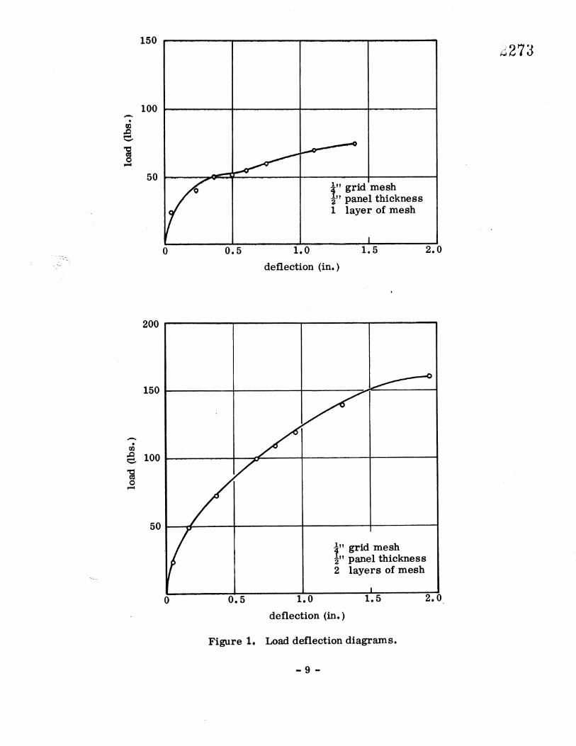
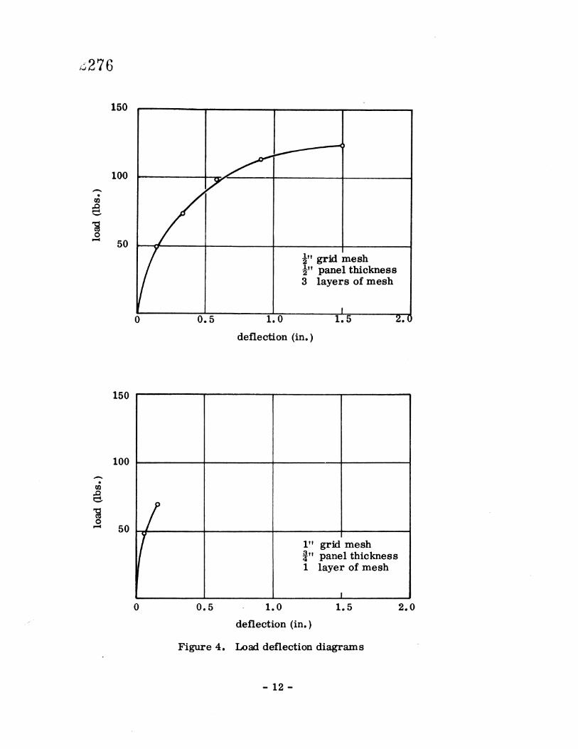
To make a determination of the strength, ductility, and durability of thin ferro- cement panels, 12 test sections, 6" wide and 36" long were cast for testing at the Virginia Highway Research Councilo Variables included the panel thickness (½" ,•,•,'•*•'4 3__,,),4 size of galvanized wire mesh openings (sometimes called hardward cloth) (¼" and ½',) and number of layers of mesh (I, 2, and 3)• After curing, these panels were tested as simply supported beams (lying fiat) loaded, at the center with a concentrated force imposed by a hydraulic testing machine. Plots of the load-deflection behavior are shown in Figures 1-6 (all figures attached)°
In addition, a few "vandalism" tests were conducted in which an 8-pound steel weight was dropped onto the panel from a height of 4•o Such impact was intended to simulate an object as a rock thrown at a panel. Only after repeated blows at the same location did spalling occur in the panel.
Uncracked portions of the test panel were then cut into 3" by 4" blocks for re- peated freeze-thaw action in a freeze-thaw machine° Unfortunately, due to a breakdown of the freeze-thaw equipment at the Research Council, final results of these tests are not available at this time°
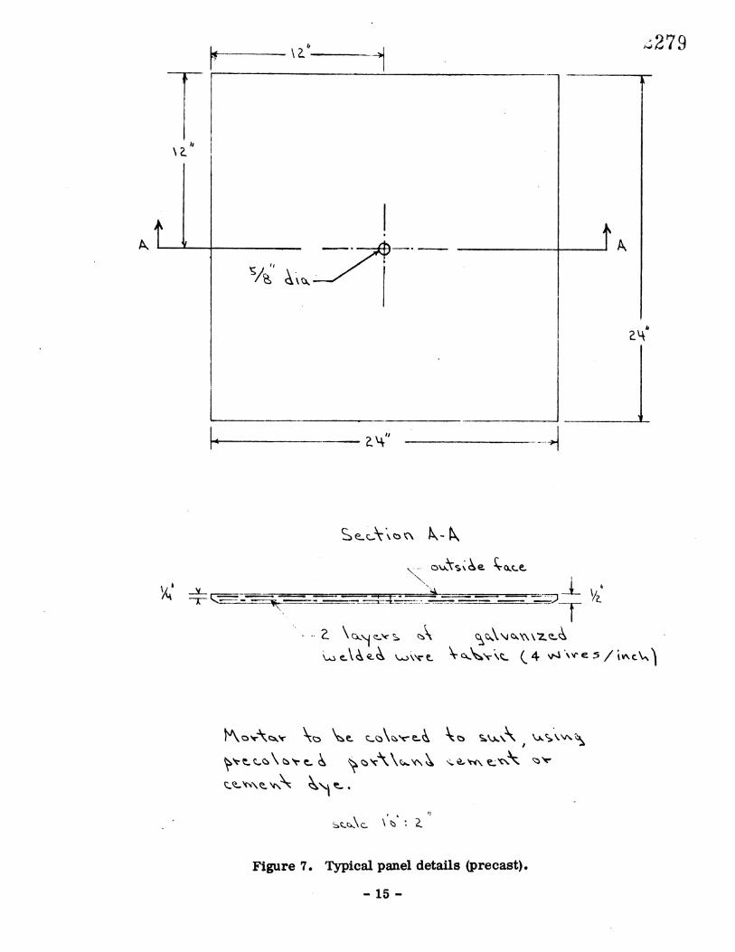
After evaluating the data, a judgement was made to use a ½" thick panel with 2 layers of ¼" galvanized welded wire mesh for the prototype panel° Details of typical prototype panels are shown in Figures 7 and 8o Coloring may be achieved through the addition of coloring dye t• the mortar m•x or through use of precolored cement which can be obtained in as many as 144 different hues. (8) In either case, the mortar mix must be exactly the same for each panel used on a given structure to maintain uniformity of color.
Figure 9 illustrates the manner of attachment of the panel to the concrete surface° The use of a stainless steel bolt will insure a maintenance free installation. A double nut on the bolt is recommended to prevent accidental loosening of the panel. By putting a little pressure on the panel through tightening of the nut, the panel will grip the concrete surface and prevent further movement. Note that the edges of the panel are beveled so as to deflect any water drip and thus prevent streaking or staining of the panel. The panel units shown in Figures 1 and 2 weigh about 25 pounds, making installation easy, and adding little extra dead weight to the structure.
Should the panels ever have to be removed, the anchor bolt arrangement shown in Figure 9 will allow such to be done without damage to the panels.
The estimated cost to produce the panel in Figure 7 is approximately $6.00, and $10o 00 for the panel in Figure 8. The estimated cost for a single fabricated stain- less steel bar with washer and nuts is about $4.00. Installation costs on existing structures is estimated to be between $5.00 and $8.00 per panel, depending on site and location. The installation for new construction would be only about $1.00 as embeddment of the bolt would be merely a matter of presetting the bolt in place prior to casting of the concrete. The total cost per panel would therefore lie between $11.00 and $22.00 A 100'-long bridge would use between 50 and 100 such panels. For new construction, architectural grooving and finishing could be minimized, thereby offsetting the cost of the panels.
If these panels were made by Highway Department maintenance personnel during "slow" periods (as in winter months), costs may be reduced even further.
SAMPLE APPLICATIONS
By varying the size, shape or color of the panels, their application on almost any sort of concrete structure is possible. Two types of highway related concrete structures appear to be most conspicuously in need of esthetic enhancement. These are overpass bridges and retaining walls, particularly those of high visibility.
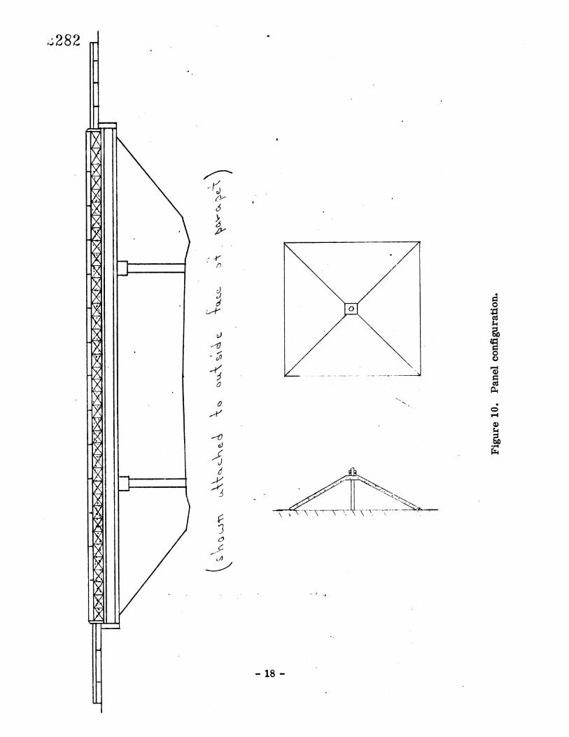
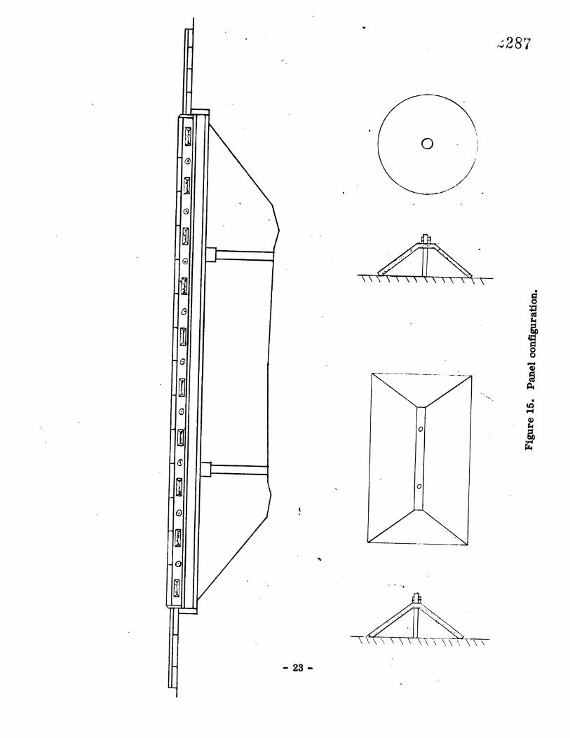
Figures 10-15 show a typical concrete bridge (actually patterned after an existing one near Charlottesville, Virginia) in which ferro-cement panels are attached to the ex- terior face of the parapet wall in various ways. The panels are used here as accent colors, which is believed to be all that is necessary to relieve the drabness of bare concrete. Coloring of all surfaces is not necessary as is generally done by painting. Obviously, many other shapes and patterns are possible with such panels. Opportunity is thus given to treat each structure uniquely if desired by using but one basic method.
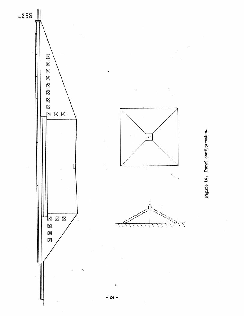
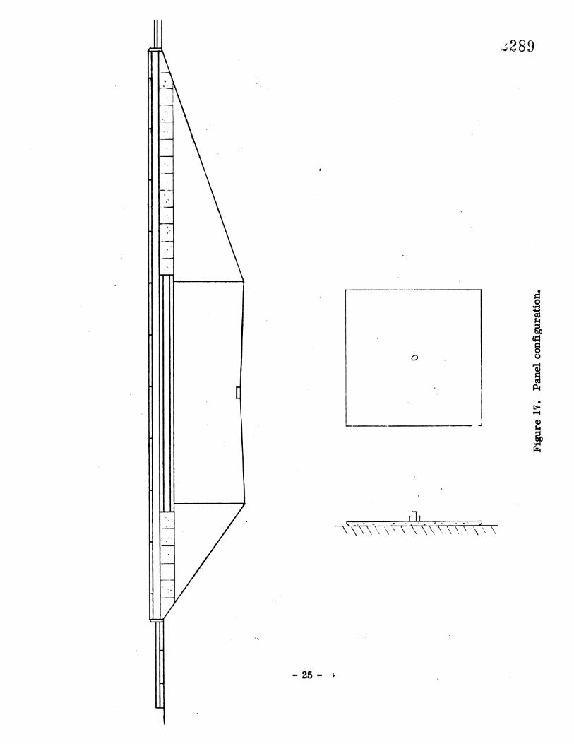
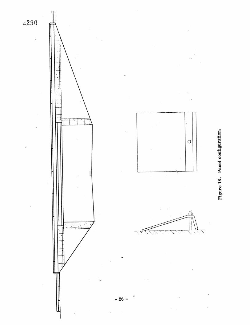
Figures 16-21 show various applications of colored panels on a bridge retaining wall (also patterned after one existing near Charlottesville). Here again, the panels are used only for accent and do not have to cover the entire wall. While covering an entire wall is possible with this method, it would be obviously much more expensive to do. The designs shown in the figures are but samples of what might be done, and in no way restrict other possibilities.
-3-

A CKNOW LE DGE MENTS
In addition to acknowledging the general support for this study provided by the Virginia Highway Research Council, the author wishes to express particular appre- ciation to Wayne D. Tucker, student assistant, who performed the physical tests on the ferro-cement panels described°
-5-

lo
REFERENCES
Zuk, Wo-, "Public Response to Bridge Colors 'r, Virginia Highway Research Council Report, August 1973.
2o Ferro-cement Boats, C•o•n_c_re_t_e, U. K., September 1973, ppo 30-32°
z272
Samson, J., and G. Wellens, How to Build a Ferro-cement Boat, Samson Marine Design, Ltdo, Lochner•-Bo Co• Canada, 1972o
Shah, S. Po, '•Ferro-Cement as a New Engineering Material", Research Report 70-11, Department of Materials Engineering, University of Illinois, Chicago, Ill.
Naaman• A E and S P Shah, "Tensile Tests on Ferro-Cement" Journal A C. Io, September 197 2o
"Impact Resistance of Ferro-Cement", Journal Shah, So P andWo Ho Key, Jr., A. S. Co E., ST-I• Paper Noo 8640, January 1972.
F__e•ro-cement_App_l__igatio•sin Devel0Pin_g Cpu_ntries_•. National Academy of Science, February 19730
"Spec-Data Sheet for Flamingo Colored Portland Cement '•, Riverton Corporation, 1973

150
100
5O
• panel thickness 1 layer of mesh
0 0.5 1.0 1.5 2.0
deflection (in.)
273
200
100
5O
','
grid mesh -' panel thickness 2 layers of mesh
0.5 1.0 1.5
deflection (in.)
Figure 1. Load deflection diagrams.
-9-
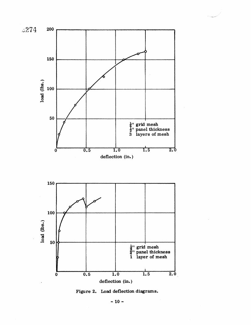
150
• 100
5O ¼" grid mesh z,, panel thickness 3 layers of mesh
deflection (in.)
150
100
0.5 z.o
" grid mesh " panel thickness
1 layer of mesh
deflection (in.)
Figure 2. Load deflection diagrams.
-10-
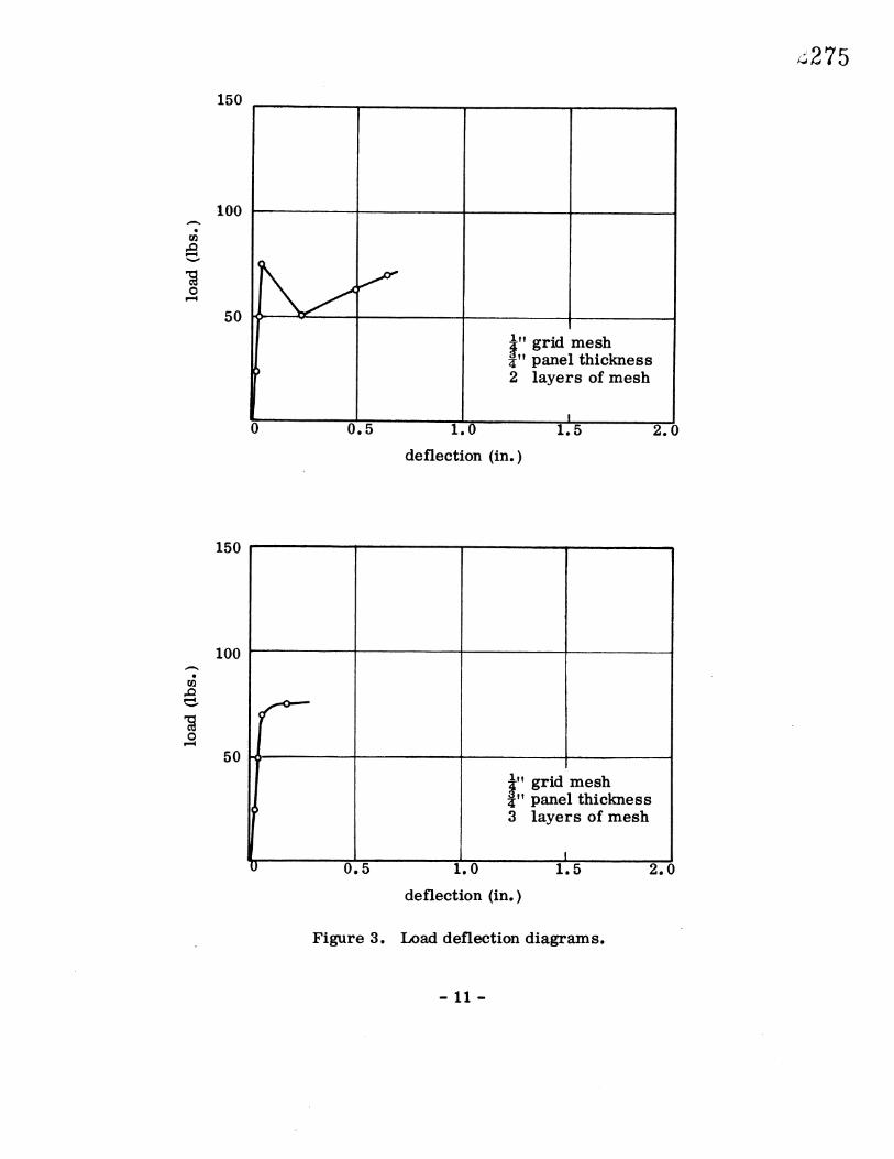
150
100
5O
'• grid mesh '• panel thickness
2 layers of mesh
1.0 1.5 2.0
deflection (in.)
150
100
5O
grid mesh panel thickness layers of mesh
0.5 1.0 1.5 2.0
deflection (in.)
Figure 3. Load deflection diagrams.
-11-
276
150
100
½" grid mesh -•'• panel thickness 2 3 layers of mesh
0 0.5 1.0 1.5
deflection (in.)
150
100
5o/
Figure 4.
1" grid mesh •" panel thickness 1 layer of mesh
1.0 1.5
deflection (in.)
Load deflection diagrams
-12-
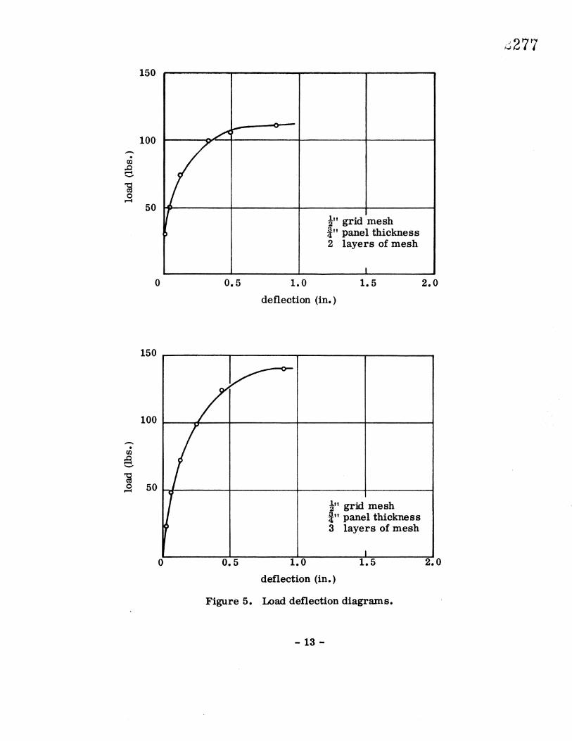
150
100
50 -•'•. grid mesh 3•! • panel thickness 2 layers of mesh
0.5 1.0 1.5
deflection (in.)
150
100
5O
-•"•. grid mesh •" panel thickness 3 layers of mesh
0.5 1.0 1.5
deflection (in.)
Figure 5. Load deflection diagrams.
13-
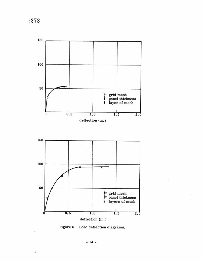
z278
150
100
o o.•
-•"•. grid mesh 1" panel thickness 1 layer of mesh
1.0 1.5 2.0
deflection (in.)
100
5O
0 5
-•"• grid mesh ½" panel thickness 2 layers of mesh
1 0 1o'5 2.•
deflection (in.)
Figure 6. Load deflection diagrams.
14-
•279
Figure 7. Typical panel details (precast).
15-
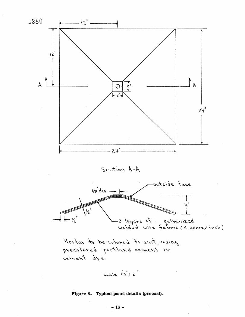
Figure 8. Typical pauel details (precast).
16-

Figure 9. Attachment of ferro-cement panels to a concrete surface.
17-
18-
19
2(}
21-
o
•286
22-
23-.
v287
"7.
25
o
•290
26
27
•291
z292
28
29