yuken hydraulic equipment - 油研工業株式会社 logic valves model no. max. operating pressure...
TRANSCRIPT
647
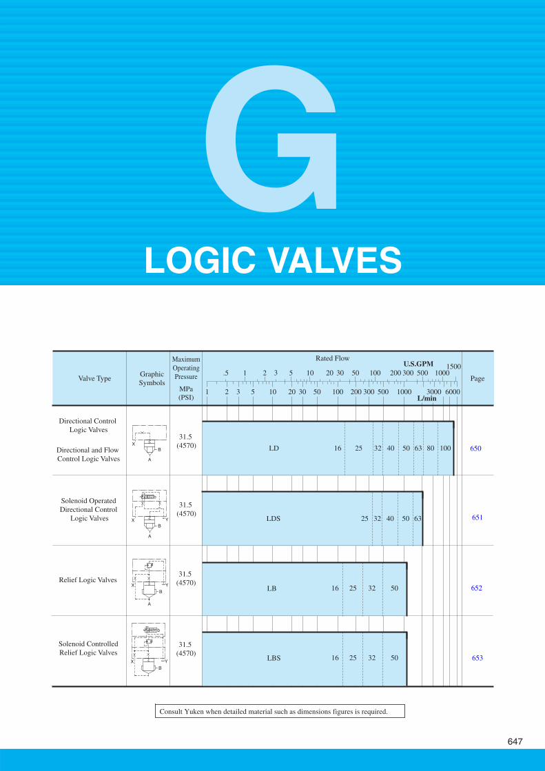
Rated Flow
Valve Type Page
651
652
653
650
31.5 (4570)
31.5 (4570)
31.5 (4570)
31.5 (4570)
Solenoid Operated Directional Control
Logic Valves
Relief Logic Valves
Solenoid Controlled Relief Logic Valves
Directional and Flow Control Logic Valves
Directional Control Logic Valves
1 2 3 5 10 20 30 50 100 200 300 500 1000 3000 6000L/min
U.S.GPM1 00555. 100 200 3005010 20 30 1000
15002 3
Maximum Operating Pressure
MPa (PSI)
Graphic Symbols
X
A
B
X
A
B
b
Y
X Y
B
A
X Y
B
b
LD 10080635040322516
LDS 6350403225
LB 50322516
LBS 50322516
Consult Yuken when detailed material such as dimensions figures is required.
GLOGIC VALVES
Logic Valves648
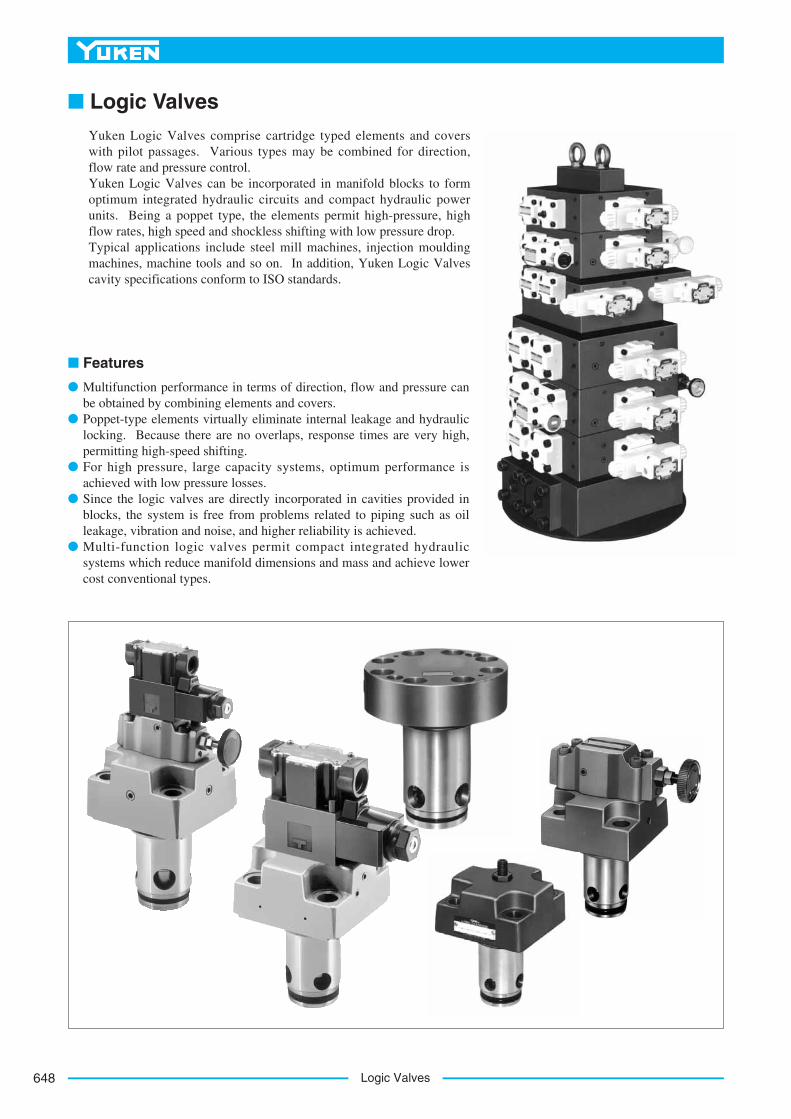
■ Logic ValvesYuken Logic Valves comprise cartridge typed elements and coverswith pilot passages. Various types may be combined for direction,flow rate and pressure control. Yuken Logic Valves can be incorporated in manifold blocks to formoptimum integrated hydraulic circuits and compact hydraulic powerunits. Being a poppet type, the elements permit high-pressure, highflow rates, high speed and shockless shifting with low pressure drop. Typical applications include steel mill machines, injection mouldingmachines, machine tools and so on. In addition, Yuken Logic Valvescavity specifications conform to ISO standards.
■ Features
● Multifunction performance in terms of direction, flow and pressure canbe obtained by combining elements and covers.
● Poppet-type elements virtually eliminate internal leakage and hydrauliclocking. Because there are no overlaps, response times are very high,permitting high-speed shifting.
● For high pressure, large capacity systems, optimum performance isachieved with low pressure losses.
● Since the logic valves are directly incorporated in cavities provided inblocks, the system is free from problems related to piping such as oilleakage, vibration and noise, and higher reliability is achieved.
● Multi-function logic valves permit compact integrated hydraulicsystems which reduce manifold dimensions and mass and achieve lowercost conventional types.
649
LOGIC VALVES
Lo
gic
Val
ves
X
A
B
G
Logic Valves
XB
A
A
XB
A
X YB
Function Graphic Symbols Working area ratio (AA : AB) Features
Poppet shape
No leakage between port A and B
Flow A to B and B to A are possible
Response time and shock can be adjusted by orifice selection.
Poppet shape With cushion (LD- - -S-1/2/3): flow control.
No leakage between port A and B
Flow A to B only is possible.
Response time and shock can be adjusted by orifice selection.
Remote and unloading control is possible with vent circuit (LB- - ).
Two or three pressure controls are possible in combination of solenoidoperated directional valve and pilot relief valve (LBS- - ).
2 : 1
24 : 1
Direction
Directionand Flow
Relief
Without cushion (LD/LDS- - ): high-speed shiftWith cushion (LD/LDS- - -S): Shockless shift
Functions, working area ratios and features
AA(100%)
AB
AX
B
BA
A
X
B
A
XX Y
BB
B
AAA
X YX
X
Y
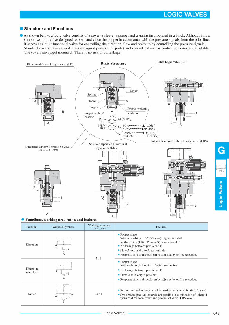
50%…………LD・LDS4.2%…………LB・LBS150%…………LD・LDS104.2%…………LB・LBS
))
((
Solenoid Operated Directional Logic Valve (LDS)
Relief Logic Valve (LB)Directional Control Logic Valve (LD) Basic Structure
CoverSpring
Sleeve
Poppet
Poppet withcushion
Ratioof
poppetarea
Directional & Flow Control Logic Valve (LD- - -S-1/2/3)
Poppet without
cushion
Solenoid Controlled Relief Logic Valve (LBS)
■ Structure and Functions
● As shown below, a logic valve consists of a cover, a sleeve, a poppet and a spring incorporated in a block. Although it is asimple two-port valve designed to open and close the poppet in accordance with the pressure signals from the pilot line,it serves as a multifunctional valve for controlling the direction, flow and pressure by controlling the pressure signals. Standard covers have several pressure signal ports (pilot ports) and control valves for control purposes are available.The covers are spigot mounted. There is no risk of oil leakage.
Logic Valves650
ModelNo.
Max.OperatingPressure
MPa (PSI)
Approx.Mass
kg(lbs.)
LD-16
LD-25
LD-32
LD-40
LD-50
LD-63
LD-80
LD-100
Rated Flow L/min
(U.S.GPM)
CrackingPressure
MPa (PSI)
Ratio of PoppetArea
130 (34.3)
350 (92.5)
500 (132)
850 (225)
1400 (370)
2100 (555)
3400 (898)
5500 (1453)
Refer to Model No.
Designation
2 : 1 (Annular
area50%)
1.6 (3.5)
3.0 (6.6)
5.3 (11.7)
9.1 (20.1)
14.8 (32.6)
29.8 (65.7)
48 (106)
86 (190)
31.5 (4570)
10080635040322516Cover Type Designation
GraphicSymbols
Valve Size
Standard(None)
WithCheckValve
(4)
WithShuttleValve
(5)
WithStroke
Adjuster(1)
WithCheck
Valve & Stroke
Adjuster(2)
WithShuttle
Valve & Stroke
Adjuster(3)
Direc-tional
&Flow
Control
Direc-tional
Control
X
B
A
X
B
A
Z1
S
X
B
A
Z1 Z2
X
B
A
X
B
A
Z1
S
X
B
A
Z1 Z2
Specifications
Model Number Designation
LD - 32 - 05 - S - 1 - X 05 - 12
Design numberLD-16, 25, 32, 40, 50, 63...12LD-80, 100...11
Designation of orifice
Location of orifice(see the table right)
no orificeNone:Pilot port XX:
Pilot port ZZ1: 1
S: Port leading to springCover type (See the table right)
None, 1, 2, 3, 4, 5Poppet shape
Without cushionNone:With cushionS:
Cracking pressure (A B)
No SpringNone:0.05 MPa (7 PSI)05:0.2 MPa (29 PSI)20:
Valve Size: 16, 25, 32, 40, 50, 63, 80, 100Directional control logic valvesDirectional & flow control logic valves
Poppet shapesThe type without a cushion and the type with a cushion are both suitable for high-speed shifting and shockless shifting respectively. For directional and flow control logic valves, be sure to specify "poppet with cushions".
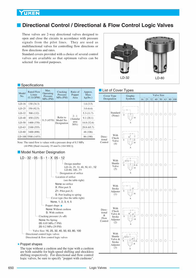
LD-32 LD-80
List of Cover Types
Note: The rated flow is values with a pressure drop of 0.3 MPa (44 PSI) [fluid viscosity 35 mm2/s (164 SSU)].
■ Directional Control / Directional & Flow Control Logic Valves
These valves are 2-way directional valves designed toopen and close the circuits in accordance with pressuresignals from the pilot lines. They are used asmultifunctional valves for controlling flow directions orflow directions and rates. Standard covers provided with a choice of several controlvalves are available so that optimum valves can beselected for control purposes.
651
LOGIC VALVES
Lo
gic
Val
ves
X
A
B
G
Logic Valves
ModelNo.
Max.OperatingPressure
MPa (PSI)
Approx.Mass
kg(lbs.)
CrackingPressure
MPa (PSI)
Rated Flow L/min
(U.S.GPM)
Ratio of PoppetArea
LDS-25
LDS-32
LDS-40
LDS-50
LDS-63
350 (92.5)
500 (132)
850 (225)
1400 (370)
2100 (555)
31.5 (4570)Refer to
Model No. Designation
2 : 1 (Annular
area50%)
4.2 (9.3)
6.5 (14.3)
10.3 (22.7)
18.6 (41.0)
33.6 (74.1)
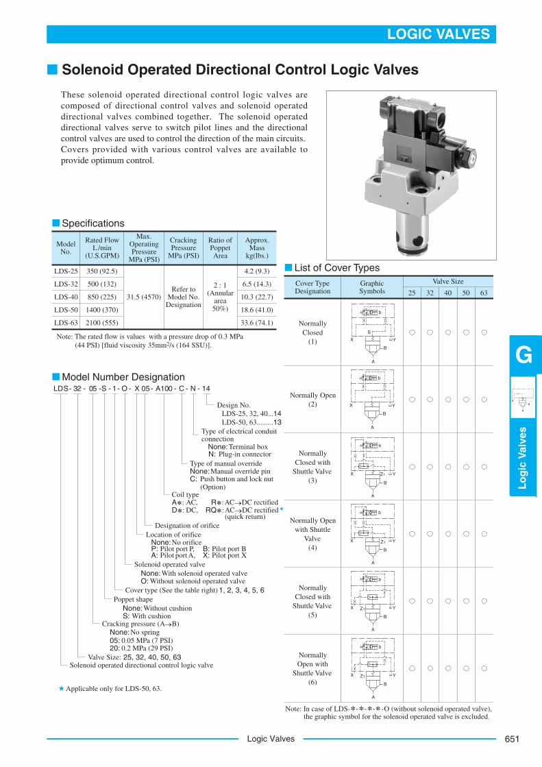
Cover Type Designation
GraphicSymbols
Valve Size
25 32 40 50 63
NormallyClosed
(1)
Normally Open (2)
NormallyClosed with
Shuttle Valve (3)
Normally Open with Shuttle
Valve(4)
NormallyClosed with
Shuttle Valve (5)
NormallyOpen with
Shuttle Valve (6)
Specifications
List of Cover Types
Model Number DesignationLDS- 32 - S- A100 C N 1405 - 1- O - - - - -X 05
Design No.LDS-25, 32, 40...14LDS-50, 63.........13
Type of electrical conduitconnection
Terminal boxPlug-in connector
None:N:
Type of manual overrideManual override pin
Push button and lock nut (Option)
None:C:
Coil typeAC,A :
D :R :
DC,AC DC rectified
RQ :AC DC rectified(quick return)
Designation of orificeLocation of orifice
No orificeNone:Pilot port P,P:
A: Pilot port A,Pilot port BB:
X: Pilot port XSolenoid operated valve
With solenoid operated valveNone:Without solenoid operated valveO:
Cover type (See the table right) 1, 2, 3, 4, 5, 6Poppet shape
Without cushionNone:With cushionS:
Cracking pressure (A B)No springNone:
0.05 MPa (7 PSI)05:0.2 MPa (29 PSI)20:
Valve Size: 25, 32, 40, 50, 63Solenoid operated directional control logic valve
Note: In case of LDS- -O (without solenoid operated valve), the graphic symbol for the solenoid operated valve is excluded.
Applicable only for LDS-50, 63.
X
B
A
S
Y
b
X
B
A
Y
b
X
B
A
Z1 Y
b
X
B
A
Z1 Y
b
X
B
A
Z1 Y
b
X
B
A
Z1 Y
b
Note: The rated flow is values with a pressure drop of 0.3 MPa (44 PSI) [fluid viscosity 35mm2/s (164 SSU)].
■ Solenoid Operated Directional Control Logic Valves
These solenoid operated directional control logic valves arecomposed of directional control valves and solenoid operateddirectional valves combined together. The solenoid operateddirectional valves serve to switch pilot lines and the directionalcontrol valves are used to control the direction of the main circuits.Covers provided with various control valves are available toprovide optimum control.
Logic Valves652
X Y
B
A
X Y
B
A
Z1
X Y
B
A
Z2
ModelNumbers
Max. Operating Pressure
MPa (PSI)
Approx.Mass
kg(lbs.)
Pres. Adj. Range
MPa (PSI)
31.5 (4570)
Max. Flow L/min
(U.S.GPM)
LB-16- - -10
LB-25- - -10
LB-32- - -11
LB-50- - -11
0.4 - 31.5 (60 - 4570)
125 (33)
250 (66)
500 (132)
1200 (317)
3.6 (7.9)
4.5 (9.9)
6.7 (14.8)
16.1 (35.5)
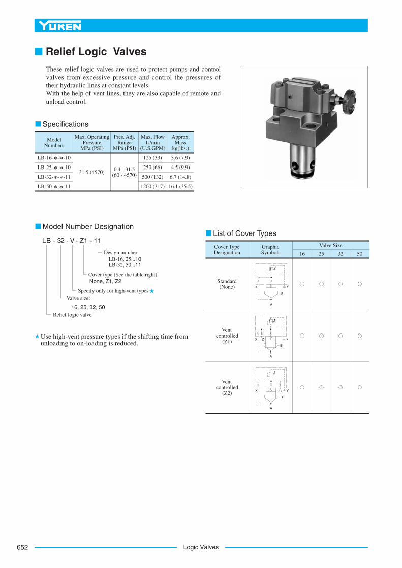
50322516Cover Type Designation
GraphicSymbols
Valve Size
Standard(None)
Ventcontrolled
(Z1)
Ventcontrolled
(Z2)
Specifications
Model Number Designation
Use high-vent pressure types if the shifting time from unloading to on-loading is reduced.
List of Cover TypesLB - 32 Z1V- - - 11
Design numberLB-16, 25...10LB-32, 50...11
Cover type (See the table right)None, Z1, Z2
Specify only for high-vent types
Valve size:
16, 25, 32, 50Relief logic valve
■ Relief Logic Valves
These relief logic valves are used to protect pumps and controlvalves from excessive pressure and control the pressures oftheir hydraulic lines at constant levels.With the help of vent lines, they are also capable of remote andunload control.
653
LOGIC VALVES
Lo
gic
Val
ves
X
A
B
G
Logic Valves
ModelNumbers
Max.OperatingPressure
MPa (PSI)
Pres. Adj. Range
MPa (PSI)
Max. Flow L/min
(U.S.GPM)
Approx. Masskg(lbs.)
31.5(4570)
0.4 - 31.5 (60 - 4570)
125 (33)
250 (66)
500 (132)
1200 (317)
7.2 (15.9)
8.1 (17.9)
10.3 (22.7)
19.7 (43.4)
8.6 (19.0)
9.5 (20.9)
11.7 (25.8)
21.1 (46.5)
LBS-16- - - -14
LBS-25- - - -14
LBS-32- - - -14
LBS-50- - - -14
Specifications
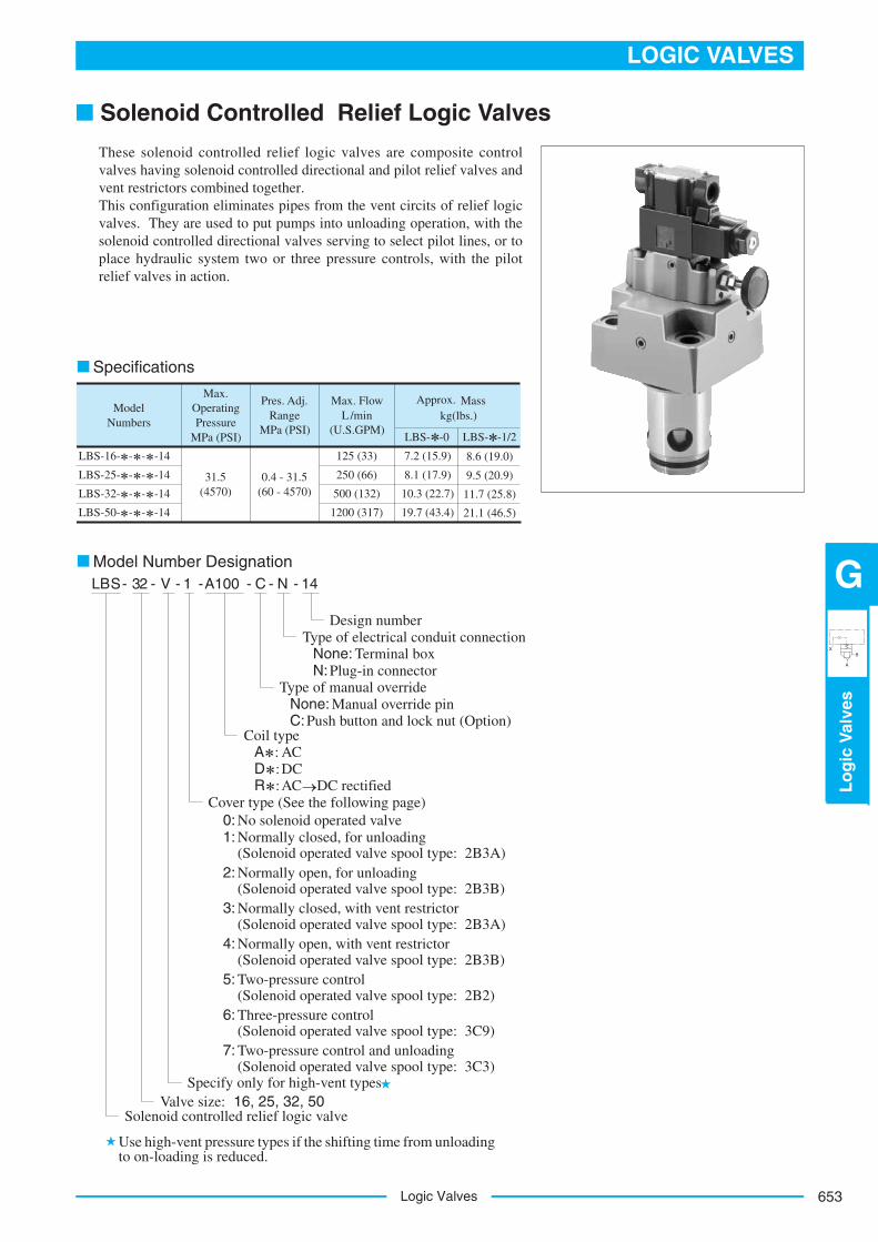
Model Number DesignationLBS- 32 - V - 1 A100- - C - N - 14
Design numberType of electrical conduit connection
Terminal boxPlug-in connector
None:N:
Type of manual overrideManual override pin
Push button and lock nut (Option)None:C:
Coil typeACA :
D :R :
DCAC DC rectified
Cover type (See the following page)0: No solenoid operated valve1: Normally closed, for unloading
(Solenoid operated valve spool type: 2B3A)2: Normally open, for unloading
(Solenoid operated valve spool type: 2B3B)3: Normally closed, with vent restrictor
(Solenoid operated valve spool type: 2B3A)4: Normally open, with vent restrictor
(Solenoid operated valve spool type: 2B3B)5:
6: Three-pressure control (Solenoid operated valve spool type: 3C9)
7: Two-pressure control and unloading (Solenoid operated valve spool type: 3C3)
Two-pressure control (Solenoid operated valve spool type: 2B2)
Specify only for high-vent typesValve size: 16, 25, 32, 50
Solenoid controlled relief logic valve
Use high-vent pressure types if the shifting time from unloading to on-loading is reduced.
LBS- -0 LBS- -1/2
■ Solenoid Controlled Relief Logic Valves
These solenoid controlled relief logic valves are composite controlvalves having solenoid controlled directional and pilot relief valves andvent restrictors combined together.This configuration eliminates pipes from the vent circits of relief logicvalves. They are used to put pumps into unloading operation, with thesolenoid controlled directional valves serving to select pilot lines, or toplace hydraulic system two or three pressure controls, with the pilotrelief valves in action.
Logic Valves654
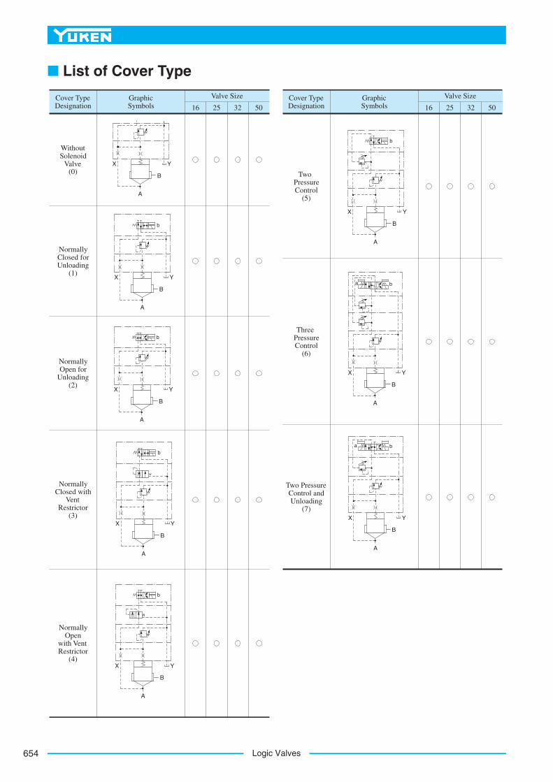
50322516Cover Type Designation
GraphicSymbols
Valve Size
50322516Cover Type Designation
GraphicSymbols
Valve Size
WithoutSolenoid
Valve(0)
NormallyClosed for Unloading
(1)
NormallyOpen for
Unloading(2)
NormallyOpen
with Vent Restrictor
(4)
NormallyClosed with
VentRestrictor
(3)
TwoPressureControl
(5)
ThreePressureControl
(6)
Two PressureControl and Unloading
(7)
X Y
B
A
b
X Y
B
A
X Y
B
A
b
X Y
B
A
b
X Y
B
A
b
X Y
B
A
b
X Y
B
A
ba
X Y
B
A
ba
■ List of Cover Type