yarway throttling valves hy-drop model 5817/ 5827 · 2 yarway throttling valves hy-drop® model...
TRANSCRIPT
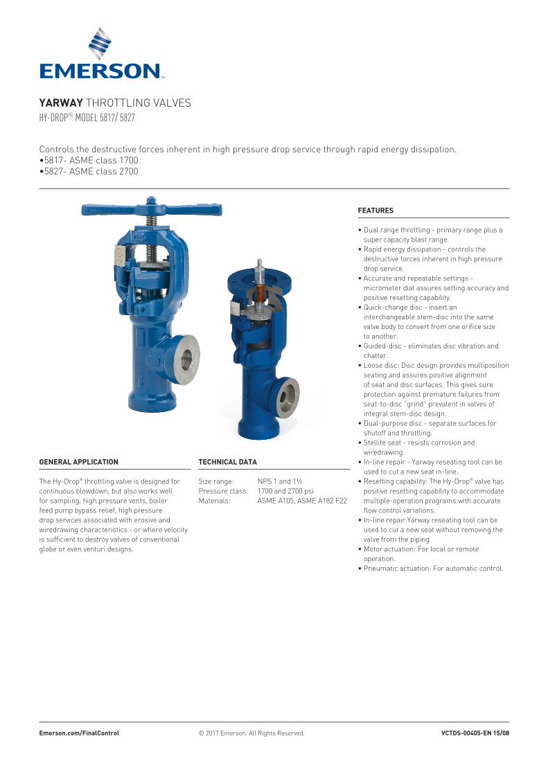
Controls the destructive forces inherent in high pressure drop service through rapid energy dissipation.•5817- ASME class 1700•5827- ASME class 2700
FEATURES
• Dual range throttling - primary range plus a super capacity blast range.
• Rapid energy dissipation - controls the destructive forces inherent in high pressure drop service.
• Accurate and repeatable settings - micrometer dial assures setting accuracy and positive resetting capability.
• Quick-change disc - insert an interchangeable stem-disc into the same valve body to convert from one orifice size to another.
• Guided-disc - eliminates disc vibration and chatter.
• Loose disc: Disc design provides multiposition seating and assures positive alignment of seat and disc surfaces. This gives sure protection against premature failures from seat-to-disc “grind” prevalent in valves of integral stem-disc design.
• Dual-purpose disc - separate surfaces for shutoff and throttling.
• Stellite seat - resists corrosion and wiredrawing.
• In-line repair - Yarway reseating tool can be used to cut a new seat in-line.
• Resetting capability: The Hy-Drop® valve has positive resetting capability to accommodate multiple-operation programs with accurate flow control variations.
• In-line repair:Yarway reseating tool can be used to cut a new seat without removing the valve from the piping.
• Motor actuation: For local or remote operation.
• Pneumatic actuation: For automatic control.
TECHNICAL DATA
Size range: NPS 1 and 1½Pressure class: 1700 and 2700 psiMaterials: ASME A105, ASME A182 F22
GENERAL APPLICATION
The Hy-Drop® throttling valve is designed for continuous blowdown, but also works well for sampling, high pressure vents, boiler feed pump bypass relief, high pressure drop services associated with erosive and wiredrawing characteristics - or where velocity is sufficient to destroy valves of conventional globe or even venturi designs.
YARWAY THROTTLING VALVESHY-DROP® MODEL 5817/ 5827
Emerson.com/FinalControl © 2017 Emerson. All Rights Reserved. VCTDS-00405-EN 15/08
2
YARWAY THROTTLING VALVESHY-DROP® MODEL 5817/ 5827
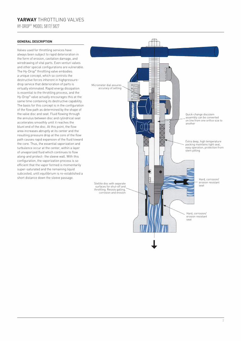
Micrometer dial assures accuracy of setting
Stellite disc with separate surfaces for shut-off and
throttling. Resists galling, corrosion and erosion
Quick-change discstem assembly can be converted on line from one orifice size to another
Extra deep, high temperature packing maintains tight seal, easy operation, protection from stem pitting
Hard, corrosion/erosion resistant seat
GENERAL DESCRIPTION
Valves used for throttling services have always been subject to rapid deterioration in the form of erosion, cavitation damage, and wiredrawing of vital parts. Even venturi valves and other special configurations are vulnerable. The Hy-Drop® throttling valve embodies a unique concept, which so controls the destructive forces inherent in highpressure-drop service that deterioration of parts is virtually eliminated. Rapid energy dissipation is essential to the throttling process, and the Hy-Drop® valve actually encourages this at the same time containing its destructive capability. The basis for this concept is in the configuration of the flow path as determined by the shape of the valve disc and seat. Fluid flowing through the annulus between disc and cylindrical seat accelerates smoothly until it reaches the blunt end of the disc. At this point, the flow area increases abruptly at its center and the resulting pressure drop at the core of the flow path causes rapid expansion of the fluid toward the core. Thus, the essential vaporization and turbulence occur at the center, within a layer of unvaporized fluid which continues to flow along-and protect- the sleeve wall. With this configuration, the vaporization process is so efficient that the vapor formed is momentarily super-saturated and the remaining liquid subcooled, until equilibrium is re-established a short distance down the sleeve passage.
Hard, corrosion/erosion resistant seat
3
3000
2000
1000900800700600
500
400
300
200
100
80
60
40
20
⅛” (3)
3/16” (5)
¼” (6)
5/16” (8)
⅜” (10)
7/16” (11)¾” (20)½” (15)
⅞” (22)
⅝” - 1”(16 - 25)
2 3 4 5 6 7 8
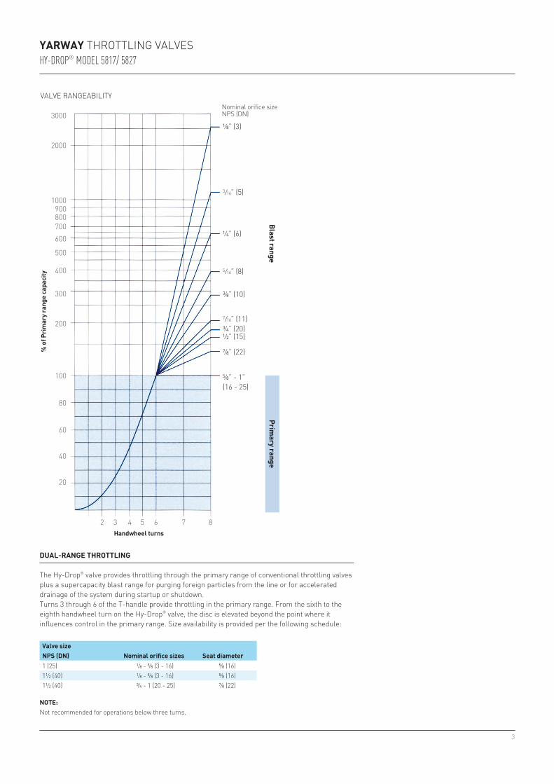
1 (25) ⅛ - ⅝ (3 - 16) ⅝ (16)1½ (40) ⅛ - ⅝ (3 - 16) ⅝ (16)1½ (40) ¾ - 1 (20 - 25) ⅞ (22)
YARWAY THROTTLING VALVESHY-DROP® MODEL 5817/ 5827
Handwheel turns
% o
f Prim
ary r
ange
capa
city
Blast rangePrim
ary range
VALVE RANGEABILITYNominal orifice size NPS (DN)
DUAL-RANGE THROTTLING
The Hy-Drop® valve provides throttling through the primary range of conventional throttling valves plus a supercapacity blast range for purging foreign particles from the line or for accelerated drainage of the system during startup or shutdown.Turns 3 through 6 of the T-handle provide throttling in the primary range. From the sixth to the eighth handwheel turn on the Hy-Drop® valve, the disc is elevated beyond the point where it influences control in the primary range. Size availability is provided per the following schedule:
NOTE:Not recommended for operations below three turns.
Valve size NPS (DN) Nominal orifice sizes Seat diameter
4
200,000 (90,719)
100,000 (45,359)
30,000 (13,608)
10,000 (4536)
3000 (1361)
1000 (454)
300 (136)
100 (45)
100
(6.9
)
200
(13.
8)
300
(20.
7)
400
(27.
6)
500
(34.
5)
600
(41.
4)
700
(48.
3)80
0 (5
3.2)
900
(62.
1)10
00 (6
9.0)
2000
(138
.0)
1”
⅞”
¾”
⅝”
½”7/16”
⅜”
5/16”
¼”
3/16”
⅛”
YARWAY THROTTLING VALVESHY-DROP® MODEL 5817/ 5827
Nominal orifice size
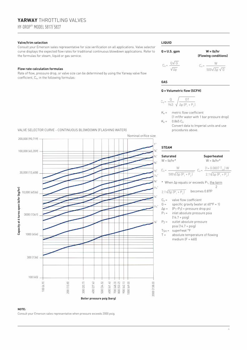
VALVE SELECTOR CURVE - CONTINUOUS BLOWDOWN (FLASHING WATER)
Boiler pressure psig (barg)
Capa
city
at 6
turn
s op
en lb
/hr (
kg/h
r)
NOTE:Consult your Emerson sales representative when pressure exceeds 2000 psig.
Valve/trim selectionConsult your Emerson sales representative for size verification on all applications. Valve selector curve displays the expected flow rates for traditional continuous blowdown applications. Refer to the formulas for steam, liquid or gas service.
Flow rate calculation formulasRate of flow, pressure drop, or valve size can be determined by using the Yarway valve flow coefficient, Cv, in the following formulas:
LIQUID
Q = U.S. gpm W = lb/hr (Flowing conditions)
GAS
Q = Volumetric flow (SCFH)
Kv = metric flow coefficient (1 m³/hr water with 1 bar pressure drop)Kv = 0.865 Cv Convert data to Imperial units and use
procedures above.
STEAM
Saturated SuperheatedW = lb/hr* W = lb/hr*
* When Δp equals or exceeds P1, the term 2 becomes 0.87P
Cv = valve flow coefficientG = specific gravity (water at 60°F = 1)Δp = (P1-P2) = pressure drop psiP1 = inlet absolute pressure psia (14.7 + psig)P2 = outlet absolute pressure
psia (14.7 + psig)TSH = superheat °FT = absolute temperature of flowing
medium (F + 460)
Cv =
Cv =
Cv =
Cv = Cv =
Q
Q GT963 ∆p (P1 + P2 )
G
G
W
W (1+ 0.0007 TSH) W
∆p ∆p
∆p (P1 + P2 ) ∆p (P1 + P2 )
500
500 2.1
∆p (P1 + P2 )2.1
Cv =
Cv =
Cv =
Cv = Cv =
Q
Q GT963 ∆p (P1 + P2 )
G
G
W
W (1+ 0.0007 TSH) W
∆p ∆p
∆p (P1 + P2 ) ∆p (P1 + P2 )
500
500 2.1
∆p (P1 + P2 )2.1
Cv =
Cv =
Cv =
Cv = Cv =
Q
Q GT963 ∆p (P1 + P2 )
G
G
W
W (1+ 0.0007 TSH) W
∆p ∆p
∆p (P1 + P2 ) ∆p (P1 + P2 )
500
500 2.1
∆p (P1 + P2 )2.1
Cv =
Cv =
Cv =
Cv = Cv =
Q
Q GT963 ∆p (P1 + P2 )
G
G
W
W (1+ 0.0007 TSH) W
∆p ∆p
∆p (P1 + P2 ) ∆p (P1 + P2 )
500
500 2.1
∆p (P1 + P2 )2.1
Cv =
Cv =
Cv =
Cv = Cv =
Q
Q GT963 ∆p (P1 + P2 )
G
G
W
W (1+ 0.0007 TSH) W
∆p ∆p
∆p (P1 + P2 ) ∆p (P1 + P2 )
500
500 2.1
∆p (P1 + P2 )2.1
Cv =
Cv =
Cv =
Cv = Cv =
Q
Q GT963 ∆p (P1 + P2 )
G
G
W
W (1+ 0.0007 TSH) W
∆p ∆p
∆p (P1 + P2 ) ∆p (P1 + P2 )
500
500 2.1
∆p (P1 + P2 )2.1
5
13111217152
102051
162122
973864
18
14
B
A
F
F
E
E D
D
P1
P2
A
D
E
F
F
P2
P1 E D
B
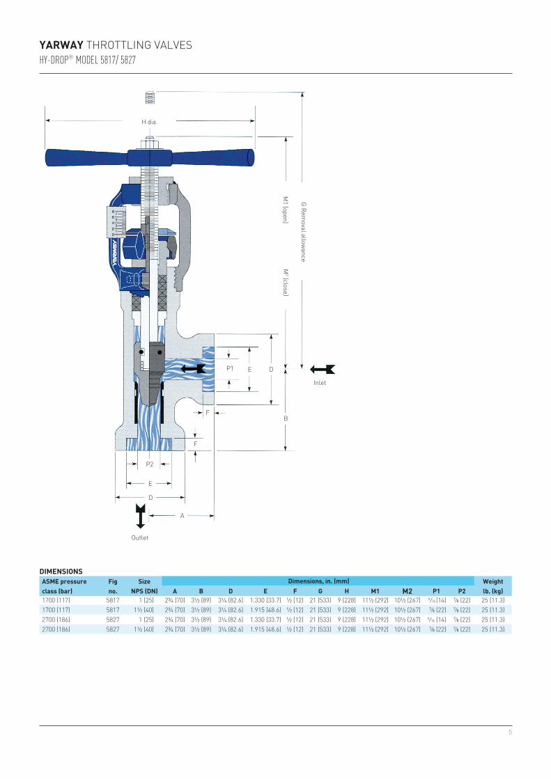
1700 (117) 5817 1 (25) 2¾ (70) 3½ (89) 3¼ (82.6) 1.330 (33.7) ½ (12) 21 (533) 9 (228) 11½ (292) 10½ (267) 9/16 (14) ⅞ (22) 25 (11.3)1700 (117) 5817 1½ (40) 2¾ (70) 3½ (89) 3¼ (82.6) 1.915 (48.6) ½ (12) 21 (533) 9 (228) 11½ (292) 10½ (267) ⅞ (22) ⅞ (22) 25 (11.3)2700 (186) 5827 1 (25) 2¾ (70) 3½ (89) 3¼ (82.6) 1.330 (33.7) ½ (12) 21 (533) 9 (228) 11½ (292) 10½ (267) 9/16 (14) ⅞ (22) 25 (11.3)2700 (186) 5827 1½ (40) 2¾ (70) 3½ (89) 3¼ (82.6) 1.915 (48.6) ½ (12) 21 (533) 9 (228) 11½ (292) 10½ (267) ⅞ (22) ⅞ (22) 25 (11.3)
YARWAY THROTTLING VALVESHY-DROP® MODEL 5817/ 5827
DIMENSIONSASME pressure class (bar)
Figno.
SizeNPS (DN)
Dimensions, in. (mm) Weightlb. (kg)A B D E F G H M1 M2 P1 P2
H dia.
G Removal allow
ance
M2 (close)
Inlet
M1 (open)
Outlet
6
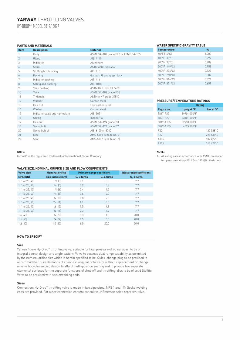
60°F (16°C) 1.000100°F (38°C) 0.997200°F (93°C) 0.982300°F (149°C) 0.958400°F (204°C) 0.927500°F (260°C) 0.887600°F (316°C) 0.824700°F (371°C) 0.659
5817-F22 1990 1000°F5827-F22 3310 1000°F5817-A105 2910 800°F5827-A105 4625 800°FF22 137 538°CF22 228 538°CA105 137 427°CA105 319 427°C
1, 1½ (25, 40) ⅛ (3) 0.1 0.3 7.71, 1½ (25, 40) 3/16 (5) 0.2 0.7 7.71, 1½ (25, 40) ¼ (6) 0.4 1.2 7.71, 1½ (25, 40) 5/16 (8) 0.6 2.0 7.71, 1½ (25, 40) ⅜ (10) 0.8 2.8 7.71, 1½ (25, 40) 7/16 (11) 1.1 3.8 7.71, 1½ (25, 40) ½ (15) 1.5 4.9 7.71, 1½ (25, 40) ⅝ (16) 2.3 7.7 7.71½ (40) ¾ (20) 3.3 11.0 20.01½ (40) ⅞ (22) 4.5 15.0 20.01½ (40) 1.0 (25) 6.0 20.0 20.0
YARWAY THROTTLING VALVESHY-DROP® MODEL 5817/ 5827
PARTS AND MATERIALSItem Description Material1 Body ASME SA-182 grade F22 or ASME SA-1052 Gland AISI 41403 Indicator Aluminum4 Stem ASTM A582 type 4165 Stuffing box bushing AISI 4106 Packing Garlock 98 and graph lock7 Indicator bushing AISI 4168 Split gland bushing AISI 10189 Yoke bushing ASTM B21 UNS C4 640010 Yoke ASME SA-182 grade F2211 T-Handle ASTM A-47 grade 3251012 Washer Carbon steel13 Hex Nut Low carbon steel14 Washer Carbon steel15 Indicator scale and nameplate AISI 30216 Spring Inconel® X17 Hex nut ASME SA-194 grade 2H18 Swing bolt ASME SA-193 grade B720 Swing bolt pin AISI 6150 or 874021 Disc AMS-5385 (stellite no. 21)22 Seat AMS-5387 (stellite no. 6)
VALVE SIZE, NOMINAL ORIFICE SIZE AND FLOW COEFFICIENTSValve size NPS (DN)
Nominal orifice size inches (mm)
Primary range coefficient Blast range coefficientCv 3 turns Cv 6 turns Cv 8 turns
WATER SPECIFIC GRAVITY TABLETemperature √G
PRESSURE/TEMPERATURE RATINGS
Figure no.Rating
psig at °F bar at °C
HOW TO SPECIFY
SizeYarway figure Hy-Drop® throttling valve, suitable for high pressure-drop services; to be of integral bonnet design and angle pattern. Valve to possess dual range capability as permitted by the nominal orifice size which is herein specified to be. Quick-change plug to be provided to accommodate future demands of change in original orifice size without replacement or change in valve body; loose disc design to afford multi-position seating and to provide two separate elemental surfaces for the separate functions of shut-off and throttling; disc to be of solid Stellite. Valve to be provided with socketwelding ends.
SizesConnection: Hy-Drop® throttling valve is made in two pipe sizes, NPS 1 and 1½. Socketwelding ends are provided. For other connection content consult your Emerson sales representative.
NOTE:1. All ratings are in accordance with ASME pressure/
temperature ratings (B16.34 - 1996) limited class.
NOTE:Inconel® is the registered trademark of International Nickel Company.
7
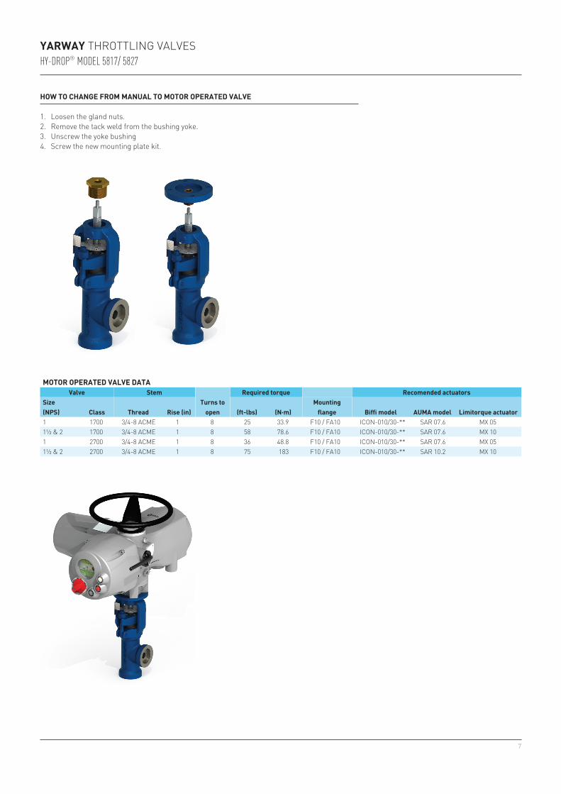
1 1700 3/4-8 ACME 1 8 25 33.9 F10 / FA10 ICON-010/30-** SAR 07.6 MX 051½ & 2 1700 3/4-8 ACME 1 8 58 78.6 F10 / FA10 ICON-010/30-** SAR 07.6 MX 101 2700 3/4-8 ACME 1 8 36 48.8 F10 / FA10 ICON-010/30-** SAR 07.6 MX 051½ & 2 2700 3/4-8 ACME 1 8 75 183 F10 / FA10 ICON-010/30-** SAR 10.2 MX 10
YARWAY THROTTLING VALVESHY-DROP® MODEL 5817/ 5827
HOW TO CHANGE FROM MANUAL TO MOTOR OPERATED VALVE
1. Loosen the gland nuts. 2. Remove the tack weld from the bushing yoke. 3. Unscrew the yoke bushing 4. Screw the new mounting plate kit.
MOTOR OPERATED VALVE DATAValve Stem Required torque Recomended actuators
Size (NPS) Class Thread Rise (in)
Turns to open (ft-lbs) (N·m)
Mounting flange Biffi model AUMA model Limitorque actuator
8
YARWAY THROTTLING VALVESHY-DROP® MODEL 5817/ 5827
Neither Emerson, Emerson Automation Solutions, nor any of their affiliated entities assumes responsibility for the selection, use or maintenance of any product. Responsibility for proper selection, use, and maintenance of any product remains solely with the purchaser and end user.
Yarway is a mark owned by one of the companies in the Emerson Automation Solutions business unit of Emerson Electric Co. Emerson Automation Solutions, Emerson and the Emerson logo are trademarks and service marks of Emerson Electric Co. All other marks are the property of their respective owners.
The contents of this publication are presented for informational purposes only, and while every effort has been made to ensure their accuracy, they are not to be construed as warranties or guarantees, express or implied, regarding the products or services described herein or their use or applicability. All sales are governed by our terms and conditions, which are available upon request. We reserve the right to modify or improve the designs or specifications of such products at any time without notice.
Emerson.com/FinalControl
OTHER PRODUCTS
Yarway blow-off valvesBasic requirements for the design and use of blow-off valves are established by the ASME power boiler code, section 1. The general form of a valve, the materials of its construction, allowable boiler pressures, and the installation of the valve are all determined by the code. Yarway blow-off valves are designed in conformance with code requirements per ASME section 1, ASME B31.1, and ASME B16.34.Yarway valves are especially designed for the punishment of blow-off service in boiler systems with pressures up to 3206 psig.The rugged construction of these valves can successfully withstand the combination of problems inherent in the service - a service in which high pressures result in high velocities which can cause wiredrawing and cavitation of metal services.Two broad categories of Yarway blow-off valves are available - those that operate on a sliding principle and those that operate on a seat-and-disc principle. They are summarized below.
Seatless valves for pressures to 935 psig (Class 250 to 600)The seatless blow-off valve is a sliding plunger type, opened and closed by means of a handwheel and nonrising stem, and sealed against leakage by packing rings above and below the ports.Ample flow area is provided in the hollow plunger; absence of projections or pockets prevents accumulation of scale and sediment that can impede flow and shorten the life of the valve. Annular space in the body permits pressure to surround the plunger, making the valve a fully balanced unit easy to operate at high pressures.This valve is available in angle or straightway styles, cast iron or steel construction, and flanged ends. Pressure classes are 250, 300 and 600.
Hardseat valves for pressures to 2455 psig (Class 600 and 1500)The hardseat valve has a seat and disc design with flow entering under the seat. It is opened and closed by means of a handwheel and threaded rising stem. The stuffing box bushing and threaded yoke bushing provide a simple, sturdy guide for the stem. This valve has been designed with thick stellite facings on the disc and seat to provide the hard wearing, anti-galling surfaces characteristic of stellite.Usual installation of this valve allows the flow to enter below the seat. As the valve is opened, the lip on the end of the disc restricts flow until the beveled edge or seating surface of the disc is well away from the seat. This minimizes wiredrawing and protects the sealing faces. The valve should be opened rapidly and fully to help increase the life of the internal parts.Hardseat valves are available in angle or straightway styles, socketweld or flanged end connections with manual or electric motor actuation. Class ratings are 600 and 1500.
Unit tandem valves for pressures to 3206 psig (Class 300 to 2500)The Yarway unit tandem valve features a one-piece steel block which serves as a common body for both blowing and sealing valves. This construction eliminates interconnecting welds, or bolts and gaskets where flanged valves are required, and makes the unit tandem a compact design.For valves with basic pressure rating to 600 psi (medium pressure unit tandem) the inlet valve is a hardseat type and the discharge valve is of the seatless type. For basic pressure ratings above 600 to 2500 psi, both inlet and discharge valves are hardseat type.All features of the Yarway single valves are contained in the unit tandem design with the additional advantage of a one-piece, heavy duty construction.