yarway process thermodynamic steam traps series … · yarway process thermodynamic steam traps...
TRANSCRIPT

YARWAY PROCESS THERMODYNAMIC STEAM TRAPS
SERIES 40/40D AND C250/260
Designed for a variety of high pressure and high capacity applications found in utility, industrial and marine service.
© 2017 Emerson. All Rights Reserved.Emerson.com/FinalControl VCTDS-02343-EN 19/05
FEATURES
• Designed to fail open.• Designed for superheat steam.• Unaffected by corrosive condensate,
freezing and steam lock.• In-line maintenance.• Designed to response to load charges.• Excellent air handling.• Small lightweight design.• Performance testing per ASME PTC-39.1,
ISO 7841 and 7842.
GENERAL APPLICATION
For condensate removal in high pressure industrial and steam systems.The C250 is typically smaller than other mechanical traps for high pressure applications.
TECHNICAL DATA
TECHNOLOGY: THERMODYNAMIC PISTON AND LEVER
Size: NPS ½, ¾, 1, 1½, 2, 3DN 15, 20, 25, 40, 50, 80
Temperature Max. design 750°F [400°C]Pressure rating: 2 to 1500 psig
[0.14 to 103 bar]Capacity: Up to 80,000 lb/hr
[36,000 kg/hr]Connections: Socket weld, Threaded,
FlangedMaterials: Chrome moly

2
A
YARWAY PROCESS THERMODYNAMIC STEAM TRAPS
PROFILE OF A PROCESS APPLICATION - GRAVITY DRAINAGE, SHELL AND TUBE HEAT EXCHANGER
Tubes, coils or jackets are used with heat exchangers, tanks or vats for heating liquids in either batch or continuous operation, typical of shell and tube heaters. Equipment is generally protected from the weather and typically features a single coil.
Heavy startup loads, followed by smaller running loads are to be expected, but without the extreme swings of weather-exposed equipment.
Adequate air venting is most important as the equipment is often run on daily or weekly schedules. Tendency is for total shutdown of equipment following completion of run or batch. Air in a heating system significantly reduces its efficiency. Air is a very poor conductor of heat and air filming on pipes and heat exchanger tubes reduces the heat transfer rate through their metal walls.
Shell and tube heater
GUIDELINES FOR TYPICAL PROCESS APPLICATIONS
Depending on the application, a process steam trap will probably have to handle heavy startup loads, often followed by smaller running loads. The trap’s function is to drain the process equipment and thus ensure that effective heat transfer is achieved (through latent heat). A few guidelines for optimum results include:• Provide an adequate size process connection
from equipment.• Locate trap below the equipment (water
runs downhill).• Use good piping practice to ensure that
clean condensate is presented to the trap.• Include air vents and vacuum breakers as
necessary for effective equipment operation.
Rotating cylinder dryer (syphon drained)
PROFILE OF A PROCESS APPLICATION - SYPHON/LIFT DRAINAGE ROTARY DRIER (USING LEVER TRAPS)
In this application, continuous drying of materials is being performed by exposure to the heated surfaces of rotating cylinders or drums. Commonly used in the manufacture of felt, rubber, textiles, paper and other sheet or fibrous materials, including foods and slurries of chemicals.
Higher start-up loads and moderate running loads are typical. When several dryers are in series, the first will have the highest load while those toward the end have progressively smaller loads. Each dryer should be trapped individually to prevent flooding. Syphon drainage is standard practice. CAUTION! Condensate moving up the syphon from the outer rim to the center of the drum is subject to reheating and flashing. Flashed condensate can break the siphon (steam binding). Therefore, steam traps must have hot discharge and fast response with the ability to handle flash steam by means of a small bleed passage. Air venting capability is an important requirement during start-up when drums or cylinders contain large amounts of air.
Steam
Steam lineAuxiliary air vent
Autoclave
Trap
Also, steam mixed with air contains fewer BTUs at a given pressure than steam alone. It is the function of a steam trap to aid in venting air from a steam system, but auxiliary thermostatic air vents are often required. Open to cooler air and closed to hotter steam they greatly speed up the air purging process. When frequent startups and shutdowns are the rule, rapid air purging is a significant factor. Yarway lever style thermodynamic traps are often favored for their excellent air handling characteristics on startup.

3
YARWAY PROCESS THERMODYNAMIC STEAM TRAPSTHE RIGHT TRAP FOR THE RIGHT APPLICATION
Why choose a thermodynamic steam trap?Thermodynamic traps are phase detectors in that they can discriminate between condensate and steam. The working principle is simple and, with only one moving part, these devices are small and rugged. There are three basic types of thermodynamic traps which differ from one another by the configuration of the valve they use to open and close a port. Each is well-adapted to a particular set of service conditions. The main thermodynamic feature that is desirable in process applications is the hot-running design and responsiveness to load changes. Thermodynamic traps also handle air very well, which is essential to an efficient heat transfer rate. This requires an understanding that steam mixed with air contains fewer BTUs at a given pressure than pure steam.
Variable orifice trapsThese traps are designed for a variety of high pressure applications found in utility, industrial and marine service. Typical applications include: fuel oil heaters, air heaters, reboilers, soot blower drains, steam separators, and shell and tube heat exchangers.
The small lightweight design and broad range of operating pressures are among the many advantages when compared to mechanical traps of the same pressure rating. Yarway variable orifice traps offer the following advantages:• Moderate capacity• Excellent air handling• Designed to fail open• Designed for superheat• In-line renewable• Long life materials• Broad range of pressure class• Integral screen• Compact and lightweight• Factory set and assembled internals• Optional blow-off valve connection• End connections - socketwelding standard• Seaworthy - shock and vibration tested
How it works - variable orifice designVariable orifice traps differentiate between the energy in cool condensate and flashing condensate as well as gases. Cool condensate opens the valve because the pressure in the chamber above the valve is low. The cool condensate readily drains through the control orifice from the chamber. Hot flashing condensate chokes the flow in the orifice and raises the chamber pressure. The increased chamber pressure closes the valve. When the valve is closed, a small amount of condensate continuously drains through the control orifice, making the trap responsive to changes in condensate load.
Lever style trapsThese traps are especially suited for outdoor service and freezing environment, and where the equipment has siphon or lift drainage. The built-in control orifice prevents steam binding as well as promoting excellent air handling. Among the typical applications are air blast heating coils, batch stills, autoclaves, reboilers, rotating cylinder dryers, and shell and tube heaters. All Yarway lever valve traps deliver consistent features such as:• High capacity - replaces traps of larger
physical size• Excellent air handling• Fail-safe in the open position to help
maintain production• Lever valve is only moving part• Stainless steel internals• Unaffected by corrosive condensate,
freezing, and water hammer• In-line maintenance - factory matched repair
kit installed in minutes• Full range operation - without adjustment• High temperature discharge
How it works - lever style designOn startup, air is handled through a control orifice. Only cool condensate or a mixture of condensate and air, will open the valve lever. As steam temperature condensate reaches the trap, flashing begins in the outlet orifice, building up pressure in the chamber above the lever. The lever closes as the chamber pressure increases. A small “control flow” permits quick response to inlet conditions. A slight drop in condensate temperature, for instance, reduces the chamber pressure, quickly opening the lever. Lever traps are designed for applications having large condensate loads and where rapid discharge of condensate is a requirement.
Chamber
Valve
Control orificeStrainer
Upper chamber
Control orifice
Lever valve
Outlet orificeInlet valve
4
4000
3500
3000
2500
2000
1500
1000
500
00 100 200 300 400 500 600 700 800 900 1000 1100
15,000
10,000
1,000
4 250
3
2
87654
3
2
5 6 7 89 100 2 3 4 5 6 7 89 1,000 2 3 4 5
500
800
1100
14001700200025003000350040004500
5000
5500
6000
300100 200706050403020
260250/260
10
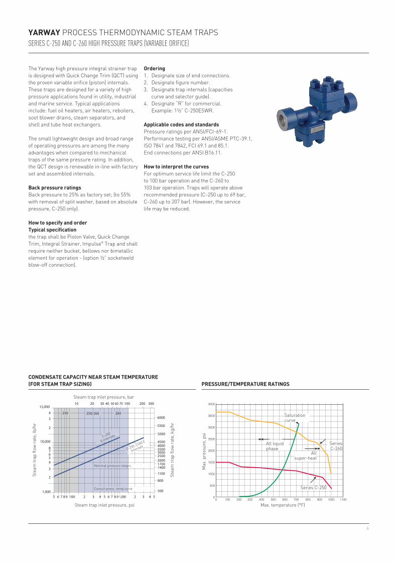
YARWAY PROCESS THERMODYNAMIC STEAM TRAPSSERIES C-250 AND C-260 HIGH PRESSURE TRAPS (VARIABLE ORIFICE)
CONDENSATE CAPACITY NEAR STEAM TEMPERATURE (FOR STEAM TRAP SIZING)
The Yarway high pressure integral strainer trap is designed with Quick Change Trim (QCT) using the proven variable orifice (piston) internals. These traps are designed for a variety of high pressure applications found in utility, industrial and marine service. Typical applications include: fuel oil heaters, air heaters, reboilers, soot blower drains, steam separators, and shell and tube heat exchangers.
The small lightweight design and broad range of operating pressures are among the many advantages when compared to mechanical traps of the same pressure rating. In addition, the QCT design is renewable in-line with factory set and assembled internals.
Back pressure ratingsBack pressure to 25% as factory set; (to 55% with removal of split washer, based on absolute pressure, C-250 only).
How to specify and orderTypical specificationthe trap shall be Piston Valve, Quick Change Trim, Integral Strainer, Impulse® Trap and shall require neither bucket, bellows nor bimetallic element for operation - (option ½” socketweld blow-off connection).
Steam trap inlet pressure, bar
Stea
m tr
ap fl
ow ra
te, l
b/hr
Stea
m tr
ap fl
ow ra
te, k
g/hr
PRESSURE/TEMPERATURE RATINGS
Max. temperature (°F)
Max
. pre
ssur
e, p
si
Saturationcurve
All liquid phase
Allsuper-heat
Series C-260
Series C-250
C-250, C260 E
Internals
C-250
G internals
Nominal pressure ranges
Consult press.-temp.curve
Steam trap inlet pressure, psi
Ordering1. Designate size of end connections.2. Designate figure number.3. Designate trap internals (capacities
curve and selector guide).4. Designate “R” for commercial. Example: 1½” C-250ESWR.
Applicable codes and standardsPressure ratings per ANSI/FCI-69-1. Performance testing per ANSI/ASME PTC-39.1, ISO 7841 and 7842, FCI 69.1 and 85.1. End connections per ANSI B16.11.
How to interpret the curvesFor optimum service life limit the C-250 to 100 bar operation and the C-260 to 103 bar operation. Traps will operate above recommended pressure (C-250 up to 69 bar, C-260 up to 207 bar). However, the service life may be reduced.

5
D
E A
C
B
4 914
15
122
11
1865781
17
16
1013
3
G H
C-250 1 (25) 11½ (292) 5 (127) 5 (127) 7½ (190) 4⅛ (105) 1.335 (34) ½ (15) 39 (18)C-250 1½ (40) 11½ (292) 5 (127) 5 (127) 7½ (190) 4⅛ (105) 1.915 (48) ½ (15) 39 (18)C-260 1 (25) 14⅜ (365) 5½ (140) 5⅛ (130) 7½ (190) 5¼ (133) 1.335 (34) ½ (15) 62 (28)C-260 1½ (40) 14⅜ (365) 5½ (140) 5⅛ (130) 7½ (190) 5¼ (133) 1.915 (48) ½ (15) 62 (28)C-260 2 (50) 14⅜ (365) 5½ (140) 5⅛ (130) 7½ (190) 5¼ (133) 2.406 (61) ⅝ (16) 62 (28)
YARWAY PROCESS THERMODYNAMIC STEAM TRAPSSERIES C-250/C-260
DIMENSIONS/WEIGHTS
Series SizeDimensions, in. (mm) Weight,
A B C D E G H lb. (kg)
MATERIALS AND SPECIFICATIONSItem Part Material1 Body Cast chrome moly ASTM A-217 Gr. WC6 .15 Max C (body)2 Trap bonnet Cast chrome moly ASTM A-217 Gr. WC6 .15 Max C (body)3 Strainer bonnet Cast chrome moly ASTM A-217 Gr. WC6 .15 Max C (body)4* Lock nut Stainless steel AISI Series 4005* Control cylinder Stainless steel AISI Series 400 mod6* Control cylinder adapter Stainless steel AISI Series 4007* Seat Steel AISI Series 400 heat treated8* Valve piece Stainless steel AISI Series 400 heat treated9* Lock pin Brass (C-250)
Monel® (C-260)10* Screen Stainless steel AISI Series 300 (0.020” perf.)11* Bonnet gasket (trap) Inconel® spiral wound non-asbestos12* Seat gasket Inconel® spiral wound non-asbestos13 Bonnet gasket (strainer) Inconel® spiral wound non-asbestos14 Stud (trap bonnet) Steel ASTM A-193 B-1615 Nut (trap bonnet) Steel ASTM A-194 Gr. 716 Stud (strainer bonnet) Steel ASTM A-193 B-1617 Nut (strainer bonnet) Steel ASTM A-194 Gr. 718* Split washer Brass (C-250 only)
* Supplied in a renewal kit

6
40D ½, ¾ 2 - 600 750 •(15, 20) (0.14 - 42) (400) •
40D 1 5 - 600 750 •(25) (0.34 - 42) (400) •
40 1-½, 2, 3 20 - 600 750 •(40, 50, 80) (1.38 - 42) (400) •
YARWAY PROCESS THERMODYNAMIC STEAM TRAPSSERIES 40/40D LEVER VALVE TRAPS
CONDENSATE CAPACITY (FOR STEAM TRAP SIZING)
RATINGS (DESIGN - FCI CLASS 600)
Series Size, in. (DN)Pressure range,
psig (bar)Max. temperature,
F° (C°)Back pressure,
psig (bar)
The Series 40/40D is designed for use in industrial process applications for pressures up to 100 bar and condensate loads to 36.300 kg/hr.
Applicable codes and standardsPressure ratings per ANSI/FCI-69-1. Performance testing per ANSI/ASME PTC-39.1. End connections per ANSI B1.20.1. for threaded ends, per ANSI B16.11 for socketwelding ends, and per ANSI B16.5 for flanged ends.
How to sizeRequired steam trap flow rate = maximum expected condensate load (lb/hr) x Safety load factor. A safety load factor of 2-4 is usually recommended. Then select a trap from the condensate capacity chart. Do not size based on end connection.
Steam trap inlet pressure, psi
Steam trap inlet pressure, bar
Stea
m fl
ow ra
te, l
b/hr
Stea
m fl
ow ra
te, b
ar
NOTE• Operates against back pressure at trap outlet up
to 40% of pressure at trap inlet. Based on absolute pressure when trap is discharging.
How to specify, order and installTypical specificationThe trap shall be thermodynamic lever valve type requiring neither bucket, float, bellows, nor bimetallic element, with stainless steel internals and chrome moly body and bonnet.
OrderingSpecify trap size and series. Threaded end connections are standard; socketwelding or flanged ends are available. Repair kits are supplied as sets of matched parts (lever valve, seat, gaskets). Order by size and series.
Installationnstall trap bonnet up in a horizontal position. Pitch lines to and from trap for gravity drainage.

7
½ 3-⅛ 2 3/16 1 9/16 2 1 3/16** 2(15) (79) (56) (40) (51) (48) (0.91)¾ 4 2 13/16 2 1/16 2⅝ 1½** 3¾(20) (102) (71) (52) (67) (38) (1.71)1 5 3 9/16 2 11/16 3½ 1¾** 8(25) (127) (90) (68) (89) (44) (3.6)
1-½ 7 4⅞ 3 9/16 4⅜ Ø 2⅝ 14(40) (178) (124) (90) (111) (67) (6.4)2 7⅝ 5⅞ 4 5/16 5⅛ Ø 3⅛ 22(50) (194) (149) (110) (130) (79) (10.0)3 10⅝ 8 3/16 6 1/16 7⅜ Ø 4⅝ 65(80) (270) (213) (154) (187) (117) (29.5)
MATERIALS AND SPECIFICATIONS SERIES 40DItem Part Material1 Body Forged Cr-Moly steel ASTM A182 F222* Bonnet Forged Cr-Moly steel ASTM A182 F113* Lever valve Stainless steel Type 410, heat treated4* Seat Stainless steel Type 410, heat treated5* Inlet valve Stainless steel Type 410, heat treated6* Bonnet gasket Monel®
7* Body gasket Monel®
8* Outlet port gasket (1” size only) Monel®
9 Cap screw Alloy steel heat treated10 Nameplate Stainless steel11 Drive screw Stainless steel12* Inlet valve rivet Stainless steel Type 41013 Spring pin Stainless steel Type 303
YARWAY PROCESS THERMODYNAMIC STEAM TRAPSSERIES 40D / SERIES 40
* NPT Standard. Socketwelding or flanged end connections also available. Consult Yarway.** Hex.
DIMENSIONS/WEIGHTS SERIES 40DSize* Dimensions, in. (mm) Weight,(DN) A B C D E lb. (kg)
DIMENSIONS/WEIGHTS SERIES 40Size* Dimensions, in. (mm) Weight,(DN) A B C D E lb. (kg)
* NPT Standard. Socketwelding or flanged end connections also available. Consult Yarway.
MATERIALS AND SPECIFICATIONS SERIES 40Item Part Material1 Body Cast Cr-Moly steel ASTM A182-F22
(size 1½” and 2”) A217-WC9 (size 3”)2 Bonnet Cast Cr-Moly steel ASTM A182-F11
(size 1½” and 2”) A217-WC6 (size 3”)3* Lever valve Stainless steel Type 4104* Seat Stainless steel Type 410, heat treated5* Inlet valve Stainless steel Type 410, heat treated6* Outlet valve Stainless steel Type 410, heat treated7* Body gasket Stainless steel spiral wound (non-asbestos)8* Bonnet gasket Stainless steel spiral wound (non-asbestos)9* Outlet port gasket Stainless steel spiral wound (non-asbestos)10 Outlet port bushing Stainless steel Type 30411 Cap screw Alloy steel heat treated12 Drive screw Stainless steel13 Nameplate Stainless steel
* Denotes available repair kit
* Denotes available repair kit
Series 40D
Series 40

8
Neither Emerson, Emerson Automation Solutions, nor any of their affiliated entities assumes responsibility for the selection, use or maintenance of any product. Responsibility for proper selection, use, and maintenance of any product remains solely with the purchaser and end user.
Yarway is a mark owned by one of the companies in the Emerson Automation Solutions business unit of Emerson Electric Co. Emerson Automation Solutions, Emerson and the Emerson logo are trademarks and service marks of Emerson Electric Co. All other marks are the property of their respective owners.
The contents of this publication are presented for informational purposes only, and while every effort has been made to ensure their accuracy, they are not to be construed as warranties or guarantees, express or implied, regarding the products or services described herein or their use or applicability. All sales are governed by our terms and conditions, which are available upon request. We reserve the right to modify or improve the designs or specifications of such products at any time without notice.
Emerson.com/FinalControl