yamada engineering handbook 2014 - double diaphragm high pressure air pumps | yamada pump · ·...
TRANSCRIPT
I
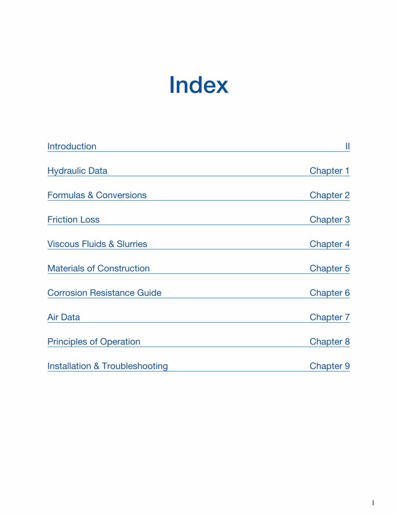
Index
Introduction II
Hydraulic Data Chapter 1
Formulas & Conversions Chapter 2
Friction Loss Chapter 3
Viscous Fluids & Slurries Chapter 4
Materials of Construction Chapter 5
Corrosion Resistance Guide Chapter 6
Air Data Chapter 7
Principles of Operation Chapter 8
Installation & Troubleshooting Chapter 9
II
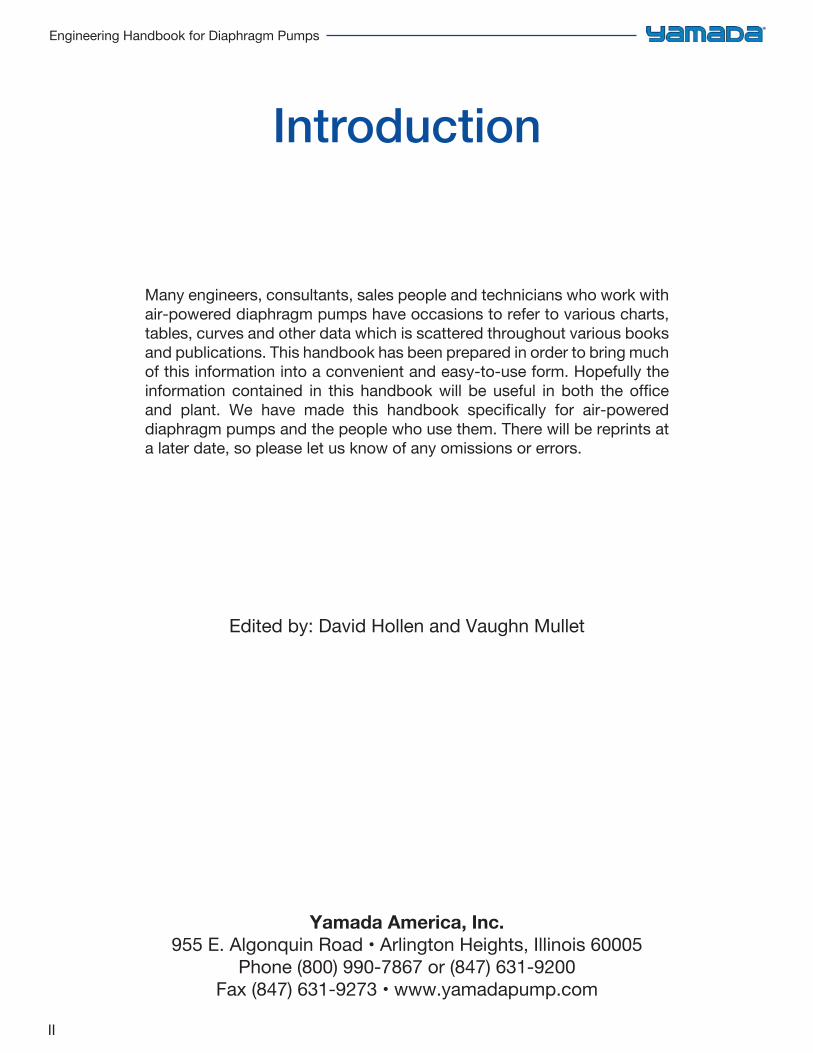
Engineering Handbook for Diaphragm Pumps
Introduction
Many engineers, consultants, sales people and technicians who work with air-powered diaphragm pumps have occasions to refer to various charts, tables, curves and other data which is scattered throughout various books and publications. This handbook has been prepared in order to bring much of this information into a convenient and easy-to-use form. Hopefully the information contained in this handbook will be useful in both the office and plant. We have made this handbook specifically for air-powered diaphragm pumps and the people who use them. There will be reprints at a later date, so please let us know of any omissions or errors.
Edited by: David Hollen and Vaughn Mullet
Yamada America, Inc.955 E. Algonquin Road • Arlington Heights, Illinois 60005
Phone (800) 990-7867 or (847) 631-9200Fax (847) 631-9273 • www.yamadapump.com
1
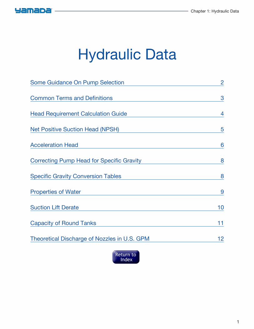
Chapter 1: Hydraulic Data
Hydraulic DataSome Guidance On Pump Selection 2
Common Terms and Definitions 3
Head Requirement Calculation Guide 4
Net Positive Suction Head (NPSH) 5
Acceleration Head 6
Correcting Pump Head for Specific Gravity 8
Specific Gravity Conversion Tables 8
Properties of Water 9
Suction Lift Derate 10
Capacity of Round Tanks 11
Theoretical Discharge of Nozzles in U.S. GPM 12
2
Engineering Handbook for Diaphragm Pumps
Some Guidance On Pump Selection
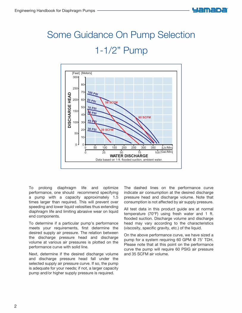
1-1/2” Pump
To prolong diaphragm life and optimize performance, one should recommend specifying a pump with a capacity approximately 1.5 times larger than required. This will prevent over speeding and lower liquid velosities thus extending diaphragm life and limiting abrasive wear on liquid end components.To determine if a particular pump’s performance meets your requirements, first determine the desired supply air pressure. The relation between the discharge pressure head and discharge volume at various air pressures is plotted on the performance curve with solid line.Next, determine if the desired discharge volume and discharge pressure head fall under the selected supply air pressure curve. If so, the pump is adequate for your needs; if not, a larger capacity pump and/or higher supply pressure is required.
The dashed lines on the performance curve indicate air consumption at the desired discharge pressure head and discharge volume. Note that consumption is not affected by air supply pressure.All test data in this product guide are at normal temperature (70°F) using fresh water and 1 ft. flooded suction. Discharge volume and discharge head may vary according to the characteristics (viscosity, specific gravity, etc.) of the liquid.On the above performance curve, we have sized a pump for a system requiring 60 GPM @ 75’ TDH. Please note that at this point on the performance curve the pump will require 60 PSIG air pressure and 35 SCFM air volume.
3
Chapter 1: Hydraulic Data
Common Terms and DefinitionsThe term “head’ by itself is rather misleading. It is commonly taken to mean the difference in elevation between the suction level and the discharge level of the liquid being pumped. Although this is partially correct, it does not include all of the conditions that should be included to give an accurate description.
FRICTION HEAD– is the pressure expressed in feet of liquid or lbs./sq. in. needed to overcome the resistance to the flow in the pipe and fittings.SUCTION LIFT– exists when the source of supply is below thecenter of the pump.SUCTION HEAD/FLOODED SUCTION– exists when the source of supply is above thecenter line of the pump. Also referred to as positive suction.STATIC SUCTION LIFT– is the vertical distance from the center line of thepump down to the free level of the liquid source.STATIC SUCTION HEAD– is the vertical distance from the center line of thepump up to the free level of the liquid source.STATIC DISCHARGE HEAD– is the vertical elevation from the center line of thepump to the point of free discharge.
DYNAMIC SUCTION LIFT– includes static suction lift, friction head loss, andvelocity head.DYNAMIC SUCTION HEAD– includes static suction head minus friction headminus velocity head.DYNAMIC DISCHARGE HEAD– includes static discharge head plus friction headplus velocity head.TOTAL DYNAMIC HEAD– includes the dynamic discharge head plusdynamic suction lift or minus dynamic suction head.VELOCITY HEAD– is the head needed to accelerate the liquid.Knowing the velocity of the liquid, the velocity head loss can be calculated by a simple formula Head=V2/2g in which g is acceleration due to gravity or 32.16 ft/sec2.
SPECIFIC GRAVITYDirect ratio of any liquid’s weight to the weight of water at 62°F. Water at 62°F weighs 8.33# per gallon and is designated 1.0 sp. gr.VISCOSITYProperty of a liquid that resists any force tending to produce flow. It is the evidence of cohesion between the particles of a fluid which causes a
liquid to offer resistance analogous to friction. An increase in the temperature usually reduces the viscosity; conversely, a temperature reduction usually increases the viscosity. Pipe friction loss increases as viscosity increases.EFFECTS OF VISCOSITYViscous liquids tend to reduce pump efficiency, reduce capacity and increase pipe friction.
4
Engineering Handbook for Diaphragm Pumps
Head Requirement Calculation Guide
Required Head = Pipe Friction Loss ± Altitude Change ± Static Pressure Change
Static head change is found by multiplying the gauge difference by 2.31
Specific Gravity
Pumping Head Required for a given capacity in gallons per minute is determined as follows:1. List all pipe fittings in separate groups according to pipe size. Save any special components (such
as heat exchanges or filters) having manufacturer’s head loss data for Step 6.2. Convert fittings to equivalent lengths of pipe for each pipe size.3. Add actual pipe length to equivalent pipe lengths of each pipe size.4. Convert total equivalent pipe length (result of Step 3) to head loss for each pipe size according to
the following formula:
Head loss = Friction loss per 100 feet of pipe
100 x total equivalent pipe length
5. Add friction losses for all pipe sizes together.6. Add head loss of special components.7. Add altitude change.8. Convert static pressure change to feet (static head change) according to following formula:
Static head change = Static pressure change (PSIG) x2.31
Specific Gravity
9. Add static head change (Step 8) to head total (thru Step 7). The resulting figure is the requiredpumping head or total dynamic head.
Pipe Friction Loss is always positive and is the head loss in feet due to friction resistance between the pipe walls and the moving liquid.Altitude Change is the elevation difference in feet between the free liquid levels of the supply source and the pump. If the receiver level is higher than the supply level, altitude change is positive. If the pump level is lower than the supply, altitude change is negative.
Static Pressure Change is the difference in PSIG between gauge pressures of the supply vessel and the receiver. If the receiver gauge pressure is higher than that of the supply vessel, the static pressure change is positive. If the receiver gauge pressure is lower than that of the supply vessel, the static pressure change is negative.
5
Chapter 1: Hydraulic Data
Net Positive Suction Head (NPSH)
Determining NPSH Available
NPSHA = (Barometer + Gauge – Vapor Pressure) x 2.31
Specific Gravity ± Static Height – Pipe
Loss
NPSH combines all the factors limiting the suction side of a pump; internal pump losses, static suction lift, friction losses, vapor pressure and atmospheric conditions. It is important to differentiate between NPSH REQUIRED and NPSH AVAILABLE.REQUIRED NPSH is a factor designed into a pump and measurable in the test laboratory by the manufacturer.AVAILABLE NPSH is the term for providing sufficient pressure on the pump suction, at the inlet port centerline, to prevent “boiling.” It is a function
of the pumping system and consists of: pressure on the liquid at its source, the elevation of the liquid with respect to the inlet centerline, losses in the suction piping and vapor pressure of the liquid.If the available NPSH is not equal to, or greater than, that required by the pump, it must be increased. This may be accomplished by increasing the static head, increasing pressure on the liquid supply surface, decreasing friction loss, or decreasing liquid temperature.
BAROMETER valve in pounds per square inch absolute (PSIA) should be the lowest likely reading for the area where the pump will be installed. (Use table, page 9, to convert barometer reading in inches of mercury to PSIA.)GAUGE PRESSURE (PSIG) is the pressure in pounds per square inch ABOVE atmospheric pressure on the surface of the liquid in the supply vessel.VAPOR PRESSURE is the value in pounds per square inch absolute (PSIA) at which the liquid will boil at a given temperature.STATIC HEIGHT is the distance in feet between the pump suction centerline and the surface level of the liquid in the supply vessel. If the surface level of the liquid is higher than the pump suction, static height is positive. If the surface level of the liquid is lower than the pump suction, static height is negative.PIPE LOSS is the friction loss in feet between the supply vessel and the pump.The NPSH information provided here is for
general use will all pumps. However, when using a diaphragm pump (reciprocating pump) some additional allowances must be made. This additional requirement is “Acceleration Head.” This is the head required to accelerate the liquid column on each suction stroke so that there will be no separation of this column in the pump or suction line.If this minimum condition is not met, the pump may experience a fluid knock caused when the liquid column, which has a vapor space between it and the diaphragm, overtakes the receding diaphragm. This knock occurs approximately two-thirds of the way through the suction stroke. If sufficient acceleration is provided for the liquid to completely follow the motion of the receding face of the diaphragm, this knock will disappear. If there is insufficient head to meet minimum acceleration requirement of NPSH, the pump will experience cavitation resulting in loss of volumetric efficiency; also, damage may occur due to the forces in collapsing the gas or vapor bubbles.
6
Engineering Handbook for Diaphragm Pumps
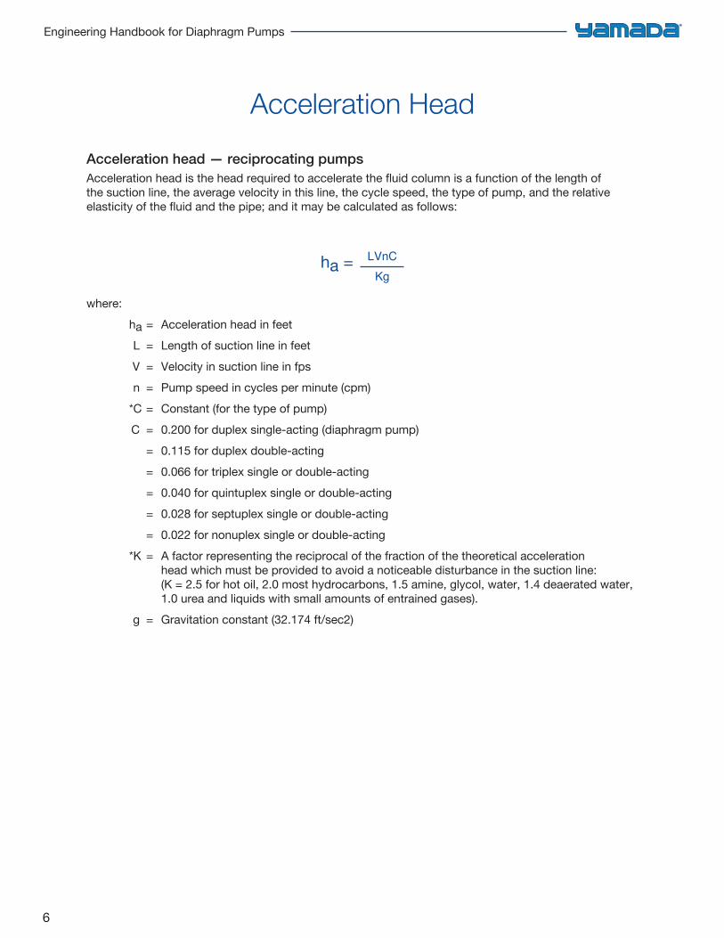
Acceleration head — reciprocating pumpsAcceleration head is the head required to accelerate the fluid column is a function of the length of the suction line, the average velocity in this line, the cycle speed, the type of pump, and the relative elasticity of the fluid and the pipe; and it may be calculated as follows:
ha = LVnC
Kg
where: ha = Acceleration head in feet L = Length of suction line in feet V = Velocity in suction line in fps n = Pump speed in cycles per minute (cpm) *C = Constant (for the type of pump) C = 0.200 for duplex single-acting (diaphragm pump)
= 0.115 for duplex double-acting= 0.066 for triplex single or double-acting= 0.040 for quintuplex single or double-acting= 0.028 for septuplex single or double-acting= 0.022 for nonuplex single or double-acting
*K = A factor representing the reciprocal of the fraction of the theoretical accelerationhead which must be provided to avoid a noticeable disturbance in the suction line: (K = 2.5 for hot oil, 2.0 most hydrocarbons, 1.5 amine, glycol, water, 1.4 deaerated water, 1.0 urea and liquids with small amounts of entrained gases).
g = Gravitation constant (32.174 ft/sec2)
Acceleration Head
7
Chapter 1: Hydraulic Data
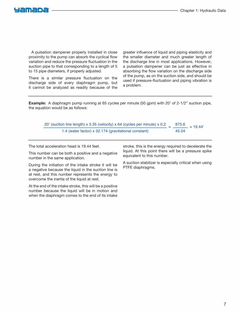
Example: A diaphragm pump running at 65 cycles per minute (50 gpm) with 20’ of 2-1/2” suction pipe, the equation would be as follows:
20’ (suction line length) x 3.35 (velocity) x 64 (cycles per minute) x 0.2
1.4 (water factor) x 32.174 (gravitational constant) =
875.6
45.04 = 19.44’
A pulsation dampener properly installed in close proximity to the pump can absorb the cyclical flow variation and reduce the pressure fluctuation in the suction pipe to that corresponding to a length of 5 to 15 pipe diameters, if properly adjusted.There is a similar pressure fluctuation on the discharge side of every diaphragm pump, but it cannot be analyzed as readily because of the
greater influence of liquid and piping elasticity and the smaller diameter and much greater length of the discharge line in most applications. However, a pulsation dampener can be just as effective in absorbing the flow variation on the discharge side of the pump, as on the suction side, and should be used if pressure-fluctuation and piping vibration is a problem.
The total acceleration head is 19.44 feet.This number can be both a positive and a negative number in the same application.During the initiation of the intake stroke it will be a negative because the liquid in the suction line is at rest, and this number represents the energy to overcome the inertia of the liquid at rest.At the end of the intake stroke, this will be a positive number because the liquid will be in motion and when the diaphragm comes to the end of its intake
stroke, this is the energy required to decelerate the liquid. At this point there will be a pressure spike equivalent to this number.A suction stabilizer is especially critical when using PTFE diaphragms.
8
Engineering Handbook for Diaphragm Pumps
Correcting Pump Head for Specific Gravity
Specific Gravity Conversion Tables
1. Pump requirement must be expressed in feet of head. If requirement is given in pounds per square inch (PSI), it may be converted to feet using this formula:
Ft. of Water = PSI x 2.31
Specific Gravity
2. Select pump from performance curve.3. Note pump air requirements.
To convert degrees API to specific gravity (liquids lighter than water)
Sp. Gr. = 141.5
131.5 + Degrees API
To convert degrees Baumé to specific gravity (liquids heavier than water)
Sp. Gr. = 145
145 – Degrees Baumé
Baumé0123456789
SpecificGravity1.0001.0061.0141.0211.0281.0351.0431.0501.0581.066
Wght.per Gal.
8.338.388.458.518.578.628.698.758.828.88
Baumé10111213141516171819
SpecificGravity1.0741.0821.0901.0981.1061.1151.1251.1321.1411.150
Wght.per Gal.
8.959.029.289.159.229.299.379.439.519.58
Baumé20212223242526272829
SpecificGravity1.1601.1691.1781.1881.1981.2081.2181.2281.2391.250
Wght.per Gal.
9.679.749.829.909.9810.0710.1510.2310.3210.42
Baumé30313233343536373839
SpecificGravity1.2601.2711.2831.2941.3061.3181.3301.3421.3551.367
Wght.per Gal.10.5010.5910.6910.7810.8810.9811.0811.1811.2911.39
Baumé40455055606570–––
SpecificGravity1.3811.4501.5261.6111.7051.8121.933
–––
Wght.per Gal.11.5112.0812.7213.4214.2115.1016.11
–––
CONVERSION TABLE BAUMÉSpecific Gravity — Weight per Gallon for liquids HEAVIER than water
API10
1112131415161718192021222324252627282930
SpecificGravity
1.0000.9930.9860.9790.9730.9660.9590.9530.9460.9400.9340.9280.9210.9160.9100.9040.8980.8930.8870.8820.876
Wght.per Gal.
8.338.278.218.168.108.047.997.947.887.837.787.737.687.637.587.537.487.437.397.347.30
API
313233343536373839404142434445464748495051
SpecificGravity
0.8710.8650.8600.8550.8500.8450.8400.8350.8300.8250.8200.8160.8110.8060.8020.7970.7930.7880.7840.7800.775
Wght.per Gal.
7.257.217.167.127.087.036.996.956.916.876.836.796.756.716.686.646.606.566.536.496.46
API
525354555657585960616263646566676869707172
SpecificGravity
0.77120.76700.76370.75970.75560.75160.74760.74370.73980.73590.73100.72830.72460.72090.71720.71360.70900.70650.70200.69950.6950
Wght.per Gal.
6.426.396.356.326.286.286.226.186.156.126.096.066.035.995.965.935.905.875.855.825.79
API
737475767778798081828384858687888990–––
SpecificGravity
0.69260.68930.68590.68260.67930.67500.67280.66960.6665.066340.66030.65720.65410.6511.064810.64520.64220.6393
–––
Wght.per Gal.
5.765.735.705.685.655.625.605.575.545.525.495.475.445.425.395.375.345.32
–––
API
919293949596979899100
–––––––––––
SpecificGravity
.36.633.630.628.625.622.619.617.614.611
–––––––––––
Wght.per Gal.
5.295.275.255.225.205.185.155.135.115.09
–––––––––––
CONVERSION TABLE APISpecific Gravity — Weight per Gallon for liquids LIGHTER than water
9
Chapter 1: Hydraulic Data
6070808590100110120130140150151152153154155156157158159160161162163164165166167168169170171172173174175176177178179180181182183184185186187188189190191192193194195196197198199200201202203204
0.260.360.510.600.700.951.271.692.222.893.723.813.904.004.104.204.314.414.524.634.744.854.975.095.215.335.465.595.725.855.996.136.276.426.566.716.877.027.187.347.517.687.858.028.208.388.578.768.959.149.349.549.759.96
10.1710.3810.6010.8311.0611.2911.5311.7712.0112.2612.51
0.590.891.21.41.62.23.03.95.06.88.89.09.29.49.79.9
10.110.410.710.911.211.511.712.012.312.612.913.313.613.914.214.514.915.215.615.916.316.717.117.417.818.318.719.119.520.020.420.921.421.822.322.823.323.824.324.925.425.926.627.127.628.228.829.430.0
0.9990.9980.9970.9960.9950.9930.9910.9890.9860.9830.9810.9810.9800.9800.9790.9790.9790.9780.9780.9780.9770.9770.9770.9760.9760.9760.9750.9750.9740.9740.9740.9730.9730.9730.9720.9720.9720.9710.9710.9710.9700.9700.9700.9690.9690.9690.9680.9680.9670.9670.9660.9660.9650.9650.9650.9640.9640.9630.9630.9630.9630.9620.9620.9620.961
205206207208209210211212213214215216217218219220221222223224225226227228229230231232233234235236237238239240241242243244245250260270280290300310320330340350360380400420440460480500520540
12.7713.0313.3013.5713.8414.1214.4114.7014.9915.2915.5915.9016.2216.5416.8617.1917.5217.8618.2118.5618.9219.2819.6520.0220.0420.7821.1721.5721.9722.3822.8023.2223.6524.0924.5324.9725.4325.8926.3626.7327.3129.8335.4441.8749.2257.5767.077.789.7103.0118.0134.6153.0195.8247.3308.8381.6466.9566.1580.8812.4962.5
30.631.232.032.633.233.934.635.436.237.037.738.439.240.040.841.642.543.344.245.045.946.847.748.649.550.551.452.553.554.555.556.657.858.859.861.062.163.364.565.666.873.287.4103.6122.8144.0168.6197.0228.4264.0305.0349.0399.2517.7663.9842.41058.51318.01630.52000.12445.52980.4
0.9610.9600.9600.9600.9590.9590.9580.9580.9570.9570.9570.9560.9560.9560.9550.9550.9550.9540.9540.9530.9530.9530.9520.9520.9510.9510.9510.9500.9500.9500.9490.9490.9480.9480.9480.9470.9470.9460.9460.9460.9450.9430.9380.9330.9270.9230.9180.9130.9080.9020.8960.8910.8860.8740.8610.8470.8330.8180.8020.7860.7670.746
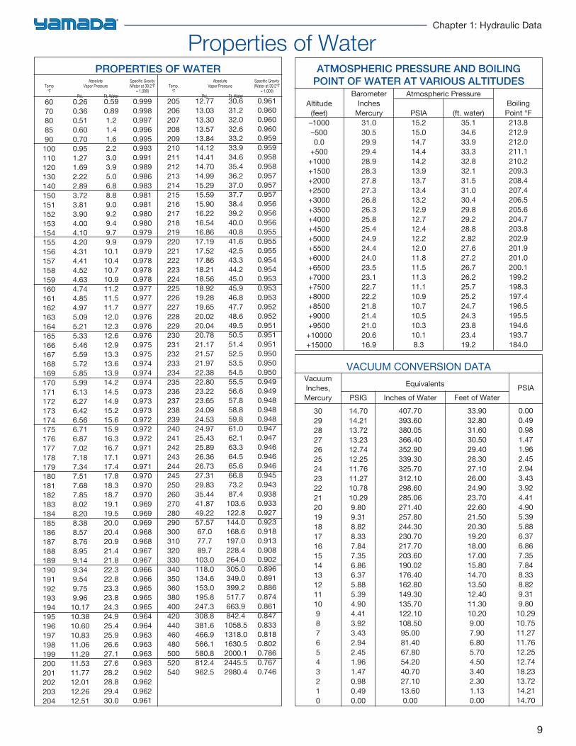
PROPERTIES OF WATERAbsolute Specific Gravity Absolute Specific Gravity
Temp Vapor Pressure (Water at 39.2°F Temp. Vapor Pressure (Water at 39.2°F°F = 1.000) °F = 1.000)
Psi. Ft. Water Psi. Ft. Water
Altitude(feet)–1000–5000.0
+500+1000+1500+2000+2500+3000+3500+4000+4500+5000+5500+6000+6500+7000+7500+8000+8500+9000+9500+10000+15000
BarometerInches
Mercury31.030.529.929.428.928.327.827.326.826.325.825.424.924.424.023.523.122.722.221.821.421.020.616.9
PSIA15.215.014.714.414.213.913.713.413.212.912.712.412.212.011.811.511.311.110.910.710.510.310.18.3
(ft. water)35.134.633.933.332.832.131.531.030.429.829.228.82.8227.627.226.726.225.725.224.724.323.823.419.2
BoilingPoint °F213.8212.9212.0211.1210.2209.3208.4207.4206.5205.6204.7203.8202.9201.9201.0200.1199.2198.3197.4196.5195.5194.6193.7184.0
ATMOSPHERIC PRESSURE AND BOILINGPOINT OF WATER AT VARIOUS ALTITUDES
Atmospheric Pressure
VACUUM CONVERSION DATAVacuumInches,Mercury
3029282726252423222120191817161514131211109876543210
PSIG14.7014.2113.7213.2312.7412.2511.7611.2710.7810.299.809.318.828.337.847.356.866.375.885.394.904.413.923.432.942.451.961.470.980.490.00
Inches of Water407.70393.60380.05366.40352.90339.30325.70312.10298.60285.06271.40257.80244.30230.70217.70203.60190.02176.40162.80149.30135.70122.10108.5095.0081.4067.8054.2040.7027.1013.600.00
Feet of Water33.9032.8031.6030.5029.4028.3027.1026.0024.9023.7022.6021.5020.3019.2018.0017.0015.8014.7013.5012.4011.3010.209.007.906.805.704.503.402.301.130.00
PSIA
0.000.490.981.471.962.452.943.433.924.414.905.395.886.376.867.357.848.338.829.319.8010.2910.7511.2711.7612.2512.7418.2313.7214.2114.70
Equivalents
Properties of Water
10
Engineering Handbook for Diaphragm Pumps
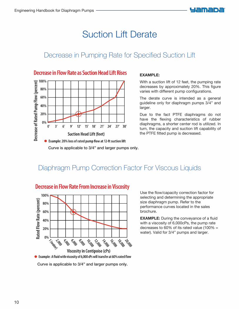
Decrease in Pumping Rate for Specified Suction Lift
EXAMPLE:
With a suction lift of 12 feet, the pumping rate decreases by approximately 20%. This figure varies with different pump configurations.The derate curve is intended as a general guideline only for diaphragm pumps 3/4” and larger.Due to the fact PTFE diaphragms do not have the flexing characteristics of rubber diaphragms, a shorter center rod is utilized. In turn, the capacity and suction lift capability of the PTFE fitted pump is decreased.
Use the flow/capacity correction factor for selecting and determining the appropriate size diaphragm pump. Refer to the performance curves located in the sales brochure.EXAMPLE: During the conveyance of a fluid with a viscosity of 6,000cPs, the pump rate decreases to 60% of its rated value (100% = water). Valid for 3/4” pumps and larger.
Diaphragm Pump Correction Factor For Viscous Liquids
Suction Lift Derate
Curve is applicable to 3/4” and larger pumps only.
Curve is applicable to 3/4” and larger pumps only.
11
Chapter 1: Hydraulic Data
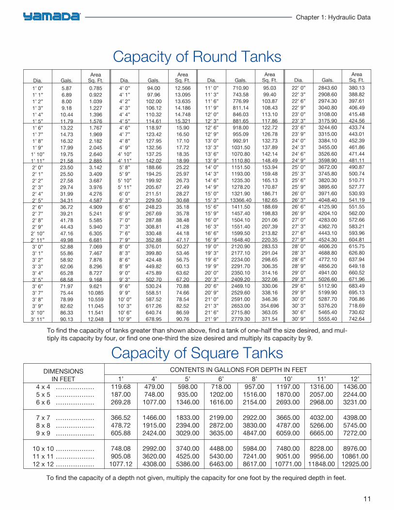
Capacity of Square Tanks
Dia.1’ 0”1’ 1”1’ 2”1’ 3”1’ 4”1’ 5”1’ 6”1’ 7”1’ 8”1’ 9”1’ 10”1’ 11”2’ 0”2’ 1”2’ 2”2’ 3”2’ 4”2’ 5”2’ 6”2’ 7”2’ 8”2’ 9”2’ 10”2’ 11”3’ 0”3’ 1”3’ 2”3’ 3”3’ 4”3’ 5”3’ 6”3’ 7”3’ 8”3’ 9”3’ 10”3’ 11”
Gals.5.876.898.009.1810.4411.7913.2214.7316.3217.9919.7521.5823.5025.5027.5829.7431.9934.3136.7239.2141.7844.4347.1649.9852.8855.8658.9262.0665.2868.5871.9775.4478.9982.6286.3390.13
AreaSq. Ft.0.7850.9221.0391.2271.3961.5761.7671.9692.1822.0452.6402.8853.1423.4093.6873.9764.2764.5874.9095.2415.5855.9406.3056.6817.0697.4677.8768.2968.7279.1689.62110.08510.55911.04511.54112.048
Dia.4’ 0”4’ 1”4’ 2”4’ 3”4’ 4”4’ 5”4’ 6”4’ 7”4’ 8”4’ 9”4’ 10”4’ 11”5’ 8”5’ 9”5’ 10”5’ 11”6’ 0”6’ 3”6’ 6”6’ 9”7’ 0”7’ 3”7’ 6”7’ 9”8’ 0”8’ 3”8’ 6”8’ 9”9’ 0”9’ 3”9’ 6”9’ 9”10’ 0”10’ 3”10’ 6”10’ 9”
Gals.94.0097.96102.00106.12110.32114.61118.97123.42127.95132.56137.25142.02188.66194.25199.92205.67211.51229.50248.23267.69287.88308.81330.48352.88376.01399.80424.48449.82475.89502.70530.24558.51587.52617.26640.74678.95
AreaSq. Ft.12.56613.09513.63514.18614.74815.32115.9016.5017.1017.7218.3518.9925.2225.9726.7327.4928.2730.6835.1835.7838.4841.2844.1847.1750.2753.4656.7560.1363.6267.2070.8874.6678.5482.5286.5990.76
Dia.11’ 0”11’ 3”11’ 6”11’ 9”12’ 0”12’ 3”12’ 6”12’ 9”13’ 0”13’ 3”13’ 6”13’ 9”14’ 0”14’ 3”14’ 6”14’ 9”15’ 0”15’ 3”15’ 6”15’ 9”16’ 0”16’ 3”16’ 6”16’ 9”19’ 0”19’ 3”19’ 6”19’ 9”20’ 0”20’ 3”20’ 6”20’ 9”21’ 0”21’ 3”21’ 6”21’ 9”
Gals.710.90743.58776.99811.14846.03881.65918.00955.09992.911031.501070.801110.801151.501193.001235.301278.201321.9013366.401411.501457.401504.101551.401599.501648.402120.902177.102234.002291.702350.102409.202469.102529.602591.002653.002715.802779.30
AreaSq. Ft.95.0399.40103.87108.43113.10117.86122.72126.78132.73137.89142.14148.49153.94159.48165.13170.87186.71182.65188.69198.83201.06207.39213.82220.35283.53291.04298.65306.35314.16322.06330.06338.16346.36354.696363.05371.54
Dia.22’ 0”22’ 3”22’ 6”22’ 9”23’ 0”23’ 3”23’ 6”23’ 9”24’ 0”24’ 3”24’ 6”24’ 9”25’ 0”25’ 3”25’ 6”25’ 9”26’ 0”26’ 3”26’ 6”26’ 9”27’ 0”27’ 3”27’ 6”27’ 9”28’ 0”28’ 3”28’ 6”28’ 9”29’ 0”29’ 3”29’ 6”29’ 9”30’ 0”30’ 3”30’ 6”30’ 9”
Gals.2843.602908.602974.303040.803108.003175.903244.603315.003384.103455.003526.603598.903672.003745.803820.303895.603971.604048.404125.904204.104283.004362.704443.104524.304606.204688.804772.104856.204941.005026.605112.905199.905287.705376.205465.405555.40
AreaSq. Ft.380.13388.82397.61406.49415.48424.56433.74443.01452.39461.86471.44481.11490.87500.74510.71527.77530.93541.19551.55562.00572.66583.21593.96604.81615.75626.80637.94649.18660.52671.96683.49695.13706.86718.69730.62742.64
Capacity of Round Tanks
To find the capacity of tanks greater than shown above, find a tank of one-half the size desired, and mul-tiply its capacity by four, or find one one-third the size desired and multiply its capacity by 9.
DIMENSIONS IN FEET
4 x 4 ………………5 x 5 ………………6 x 6 ………………
7 x 7 ………………8 x 8 ………………9 x 9 ………………
10 x 10 ………………11 x 11 ………………12 x 12 ………………
1’119.68187.00269.28
366.52478.72605.88
748.08905.081077.12
4’479.00748.001077.00
1466.001915.002424.00
2992.003620.004308.00
5’598.00935.001346.00
1833.002394.003029.00
3740.004525.005386.00
6’718.001202.001616.00
2199.002872.003635.00
4488.005430.006463.00
8’957.001516.002154.00
2922.003830.004847.00
5984.007241.008617.00
10’1197.001870.002693.00
3665.004787.006059.00
7480.009051.0010771.00
11’1316.002057.002968.00
4032.005266.006665.00
8228.009956.0011848.00
12’1436.002244.003231.00
4398.005745.007272.00
8976.0010861.0012925.00
To find the capacity of a depth not given, multiply the capacity for one foot by the required depth in feet.
CONTENTS IN GALLONS FOR DEPTH IN FEET
12
Engineering Handbook for Diaphragm Pumps
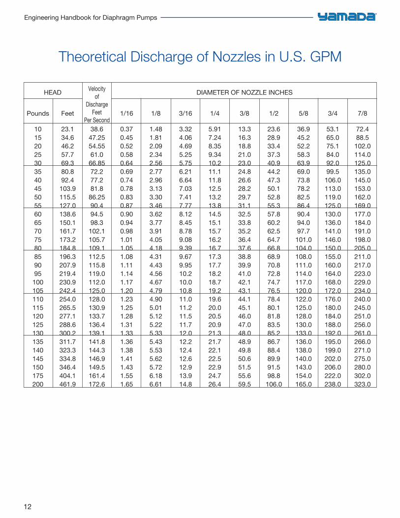
HEAD DIAMETER OF NOZZLE INCHES
Pounds Feet 1/16 1/8 3/16 1/4 3/8 1/2 5/8 3/4 7/8
10 23.1 38.6 0.37 1.48 3.32 5.91 13.3 23.6 36.9 53.1 72.4 15 34.6 47.25 0.45 1.81 4.06 7.24 16.3 28.9 45.2 65.0 88.5 20 46.2 54.55 0.52 2.09 4.69 8.35 18.8 33.4 52.2 75.1 102.0 25 57.7 61.0 0.58 2.34 5.25 9.34 21.0 37.3 58.3 84.0 114.0 30 69.3 66.85 0.64 2.56 5.75 10.2 23.0 40.9 63.9 92.0 125.0 35 80.8 72.2 0.69 2.77 6.21 11.1 24.8 44.2 69.0 99.5 135.0 40 92.4 77.2 0.74 2.96 6.64 11.8 26.6 47.3 73.8 106.0 145.0 45 103.9 81.8 0.78 3.13 7.03 12.5 28.2 50.1 78.2 113.0 153.0 50 115.5 86.25 0.83 3.30 7.41 13.2 29.7 52.8 82.5 119.0 162.0 55 127.0 90.4 0.87 3.46 7.77 13.8 31.1 55.3 86.4 125.0 169.0 60 138.6 94.5 0.90 3.62 8.12 14.5 32.5 57.8 90.4 130.0 177.0 65 150.1 98.3 0.94 3.77 8.45 15.1 33.8 60.2 94.0 136.0 184.0 70 161.7 102.1 0.98 3.91 8.78 15.7 35.2 62.5 97.7 141.0 191.0 75 173.2 105.7 1.01 4.05 9.08 16.2 36.4 64.7 101.0 146.0 198.0 80 184.8 109.1 1.05 4.18 9.39 16.7 37.6 66.8 104.0 150.0 205.0 85 196.3 112.5 1.08 4.31 9.67 17.3 38.8 68.9 108.0 155.0 211.0 90 207.9 115.8 1.11 4.43 9.95 17.7 39.9 70.8 111.0 160.0 217.0 95 219.4 119.0 1.14 4.56 10.2 18.2 41.0 72.8 114.0 164.0 223.0 100 230.9 112.0 1.17 4.67 10.0 18.7 42.1 74.7 117.0 168.0 229.0 105 242.4 125.0 1.20 4.79 10.8 19.2 43.1 76.5 120.0 172.0 234.0 110 254.0 128.0 1.23 4.90 11.0 19.6 44.1 78.4 122.0 176.0 240.0 115 265.5 130.9 1.25 5.01 11.2 20.0 45.1 80.1 125.0 180.0 245.0 120 277.1 133.7 1.28 5.12 11.5 20.5 46.0 81.8 128.0 184.0 251.0 125 288.6 136.4 1.31 5.22 11.7 20.9 47.0 83.5 130.0 188.0 256.0 130 300.2 139.1 1.33 5.33 12.0 21.3 48.0 85.2 133.0 192.0 261.0 135 311.7 141.8 1.36 5.43 12.2 21.7 48.9 86.7 136.0 195.0 266.0 140 323.3 144.3 1.38 5.53 12.4 22.1 49.8 88.4 138.0 199.0 271.0 145 334.8 146.9 1.41 5.62 12.6 22.5 50.6 89.9 140.0 202.0 275.0 150 346.4 149.5 1.43 5.72 12.9 22.9 51.5 91.5 143.0 206.0 280.0 175 404.1 161.4 1.55 6.18 13.9 24.7 55.6 98.8 154.0 222.0 302.0 200 461.9 172.6 1.65 6.61 14.8 26.4 59.5 106.0 165.0 238.0 323.0
Velocityof
DischargeFeet
Per Second
Theoretical Discharge of Nozzles in U.S. GPM
13
Chapter 2: Formulas & Conversions
English Standard to Metric 14
Metric Flow Formulas 15
Symbols 15
United States Standard Baume Scales 16
Relation Between Specific Gravity and Degree API at 60°F 17
Relation Between Specific Gravity and Degrees Brix 18
Conversion Factors-Water Analysis 19
Pounds Per Cubic Foot at Various Specific Gravities 19
Fahrenheit/Celsius Graph 20
Temperature Conversion Chart 21
Decimal and Metric Equivalents 22
Formulas & Conversions
14
Engineering Handbook for Diaphragm Pumps
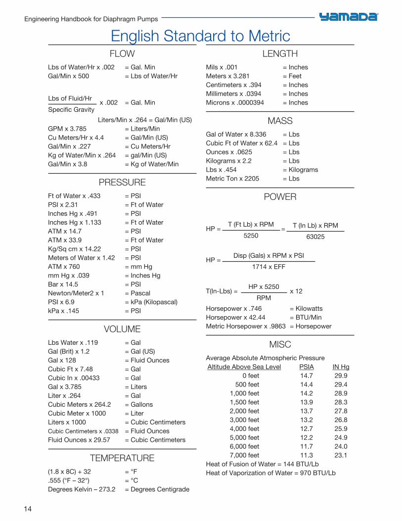
FLOWLbs of Water/Hr x .002 = Gal. MinGal/Min x 500 = Lbs of Water/Hr
Lbs of Fluid/HrSpecific Gravity
x .002 = Gal. Min
Liters/Min x .264 = Gal/Min (US)GPM x 3.785 = Liters/MinCu Meters/Hr x 4.4 = Gal/Min (US)Gal/Min x .227 = Cu Meters/HrKg of Water/Min x .264 = gal/Min (US)Gal/Min x 3.8 = Kg of Water/Min
PRESSUREFt of Water x .433 = PSIPSI x 2.31 = Ft of WaterInches Hg x .491 = PSIInches Hg x 1.133 = Ft of WaterATM x 14.7 = PSIATM x 33.9 = Ft of WaterKg/Sq cm x 14.22 = PSIMeters of Water x 1.42 = PSIATM x 760 = mm Hgmm Hg x .039 = Inches HgBar x 14.5 = PSINewton/Meter2 x 1 = PascalPSI x 6.9 = kPa (Kilopascal)kPa x .145 = PSI
VOLUMELbs Water x .119 = GalGal (Brit) x 1.2 = Gal (US)Gal x 128 = Fluid OuncesCubic Ft x 7.48 = GalCubic In x .00433 = GalGal x 3.785 = LitersLiter x .264 = GalCubic Meters x 264.2 = GallonsCubic Meter x 1000 = LiterLiters x 1000 = Cubic CentimetersCubic Centimeters x .0338 = Fluid OuncesFluid Ounces x 29.57 = Cubic Centimeters
TEMPERATURE(1.8 x 8C) + 32 = °F.555 (°F – 32°) = °CDegrees Kelvin – 273.2 = Degrees Centigrade
LENGTHMils x .001 = InchesMeters x 3.281 = FeetCentimeters x .394 = InchesMillimeters x .0394 = InchesMicrons x .0000394 = Inches
MASSGal of Water x 8.336 = LbsCubic Ft of Water x 62.4 = LbsOunces x .0625 = LbsKilograms x 2.2 = LbsLbs x .454 = KilogramsMetric Ton x 2205 = Lbs
POWER
HP = T (Ft Lb) x RPM5250
=
HP = Disp (Gals) x RPM x PSI1714 x EFF
T(In-Lbs) = HP x 5250RPM
x 12
Horsepower x .746 = KilowattsHorsepower x 42.44 = BTU/MinMetric Horsepower x .9863 = Horsepower
MISCAverage Absolute Atmospheric Pressure Altitude Above Sea Level PSIA IN Hg
0 feet 14.7 29.9 500 feet 14.4 29.4 1,000 feet 14.2 28.9 1,500 feet 13.9 28.3 2,000 feet 13.7 27.8 3,000 feet 13.2 26.8 4,000 feet 12.7 25.9 5,000 feet 12.2 24.9 6,000 feet 11.7 24.0 7,000 feet 11.3 23.1Heat of Fusion of Water = 144 BTU/LbHeat of Vaporization of Water = 970 BTU/Lb
English Standard to Metric
T (In Lb) x RPM63025
15
Chapter 2: Formulas & Conversions
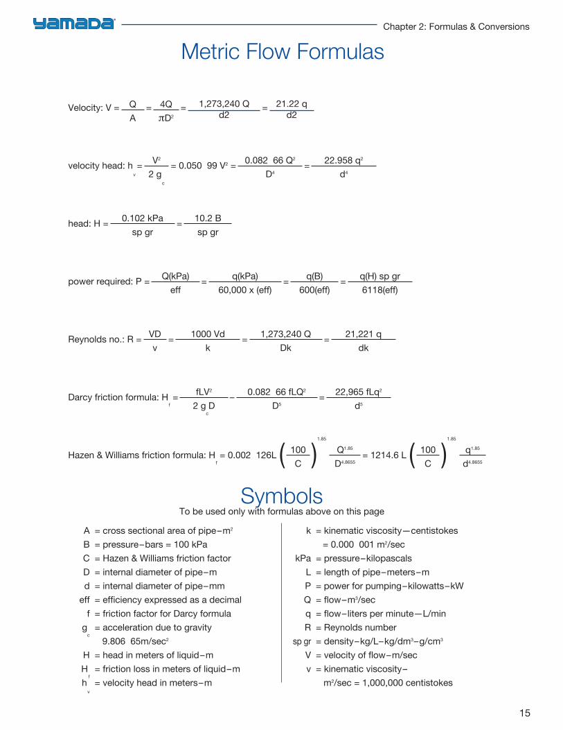
Velocity: V = QA
= 4QπD2
= 1,273,240 Qd2
= 21.22 qd2
velocity head: hv = V2
2 gc
= 0.050 99 V2 = 0.082 66 Q2
D4= 22.958 q2
d4
head: H = 0.102 kPasp gr
= 10.2 Bsp gr
power required: P = Q(kPa)eff
= q(kPa)60,000 x (eff)
= q(B)600(eff)
= q(H) sp gr6118(eff)
Reynolds no.: R = VDv
= 1000 Vdk
= 1,273,240 QDk
= 21,221 qdk
Darcy friction formula: Hf = fLV2
2 gcD
– 0.082 66 fLQ2
D5= 22,965 fLq2
d5
Hazen & Williams friction formula: Hf = 0.002 126L ( 100
C )1.85
Q1.85
D4.8655= 1214.6 L ( 100
C )1.85
q1.85
d4.8655
A = cross sectional area of pipe–m2
B = pressure–bars = 100 kPa C = Hazen & Williams friction factor D = internal diameter of pipe–m d = internal diameter of pipe–mm eff = efficiency expressed as a decimal f = friction factor for Darcy formula g
c = acceleration due to gravity
9.806 65m/sec2
H = head in meters of liquid–m H
f = friction loss in meters of liquid–m
hv = velocity head in meters–m
k = kinematic viscosity—centistokes = 0.000 001 m2/sec kPa = pressure–kilopascals L = length of pipe–meters–m P = power for pumping–kilowatts–kW Q = flow–m3/sec q = flow–liters per minute—L/min R = Reynolds number sp gr = density–kg/L–kg/dm3–g/cm3
V = velocity of flow–m/sec v = kinematic viscosity– m2/sec = 1,000,000 centistokes
SymbolsTo be used only with formulas above on this page
Metric Flow Formulas
16
Engineering Handbook for Diaphragm Pumps
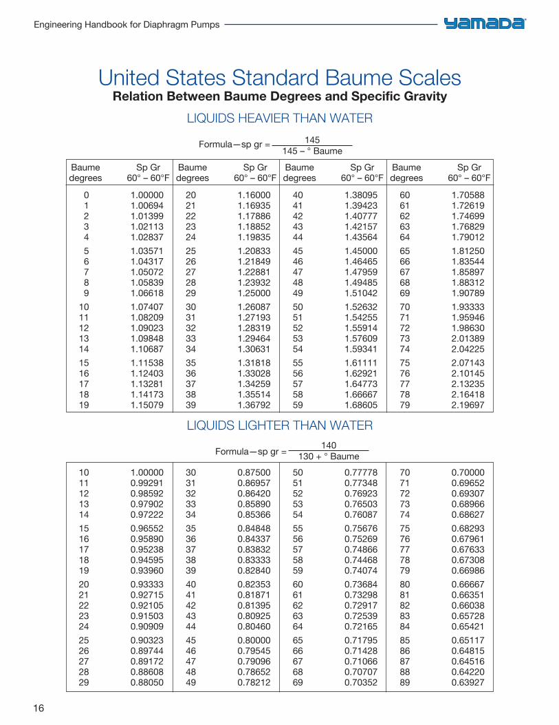
United States Standard Baume ScalesRelation Between Baume Degrees and Specific Gravity
LIQUIDS HEAVIER THAN WATER
Formula—sp gr = 145145 – ° Baume
LIQUIDS LIGHTER THAN WATER
Formula—sp gr = 140130 + ° Baume
Baume Sp Gr degrees 60° – 60°F
0 1.00000 1 1.00694 2 1.01399 3 1.02113 4 1.02837 5 1.03571 6 1.04317 7 1.05072 8 1.05839 9 1.06618 10 1.07407 11 1.08209 12 1.09023 13 1.09848 14 1.10687 15 1.11538 16 1.12403 17 1.13281 18 1.14173 19 1.15079
Baume Sp Gr degrees 60° – 60°F
20 1.16000 21 1.16935 22 1.17886 23 1.18852 24 1.19835 25 1.20833 26 1.21849 27 1.22881 28 1.23932 29 1.25000 30 1.26087 31 1.27193 32 1.28319 33 1.29464 34 1.30631 35 1.31818 36 1.33028 37 1.34259 38 1.35514 39 1.36792
Baume Sp Gr degrees 60° – 60°F
40 1.38095 41 1.39423 42 1.40777 43 1.42157 44 1.43564 45 1.45000 46 1.46465 47 1.47959 48 1.49485 49 1.51042 50 1.52632 51 1.54255 52 1.55914 53 1.57609 54 1.59341 55 1.61111 56 1.62921 57 1.64773 58 1.66667 59 1.68605
Baume Sp Gr degrees 60° – 60°F
60 1.70588 61 1.72619 62 1.74699 63 1.76829 64 1.79012 65 1.81250 66 1.83544 67 1.85897 68 1.88312 69 1.90789 70 1.93333 71 1.95946 72 1.98630 73 2.01389 74 2.04225 75 2.07143 76 2.10145 77 2.13235 78 2.16418 79 2.19697
10 1.00000 11 0.99291 12 0.98592 13 0.97902 14 0.97222 15 0.96552 16 0.95890 17 0.95238 18 0.94595 19 0.93960 20 0.93333 21 0.92715 22 0.92105 23 0.91503 24 0.90909 25 0.90323 26 0.89744 27 0.89172 28 0.88608 29 0.88050
30 0.87500 31 0.86957 32 0.86420 33 0.85890 34 0.85366 35 0.84848 36 0.84337 37 0.83832 38 0.83333 39 0.82840 40 0.82353 41 0.81871 42 0.81395 43 0.80925 44 0.80460 45 0.80000 46 0.79545 47 0.79096 48 0.78652 49 0.78212
50 0.77778 51 0.77348 52 0.76923 53 0.76503 54 0.76087 55 0.75676 56 0.75269 57 0.74866 58 0.74468 59 0.74074 60 0.73684 61 0.73298 62 0.72917 63 0.72539 64 0.72165 65 0.71795 66 0.71428 67 0.71066 68 0.70707 69 0.70352
70 0.70000 71 0.69652 72 0.69307 73 0.68966 74 0.68627 75 0.68293 76 0.67961 77 0.67633 78 0.67308 79 0.66986 80 0.66667 81 0.66351 82 0.66038 83 0.65728 84 0.65421 85 0.65117 86 0.64815 87 0.64516 88 0.64220 89 0.63927
17
Chapter 2: Formulas & Conversions
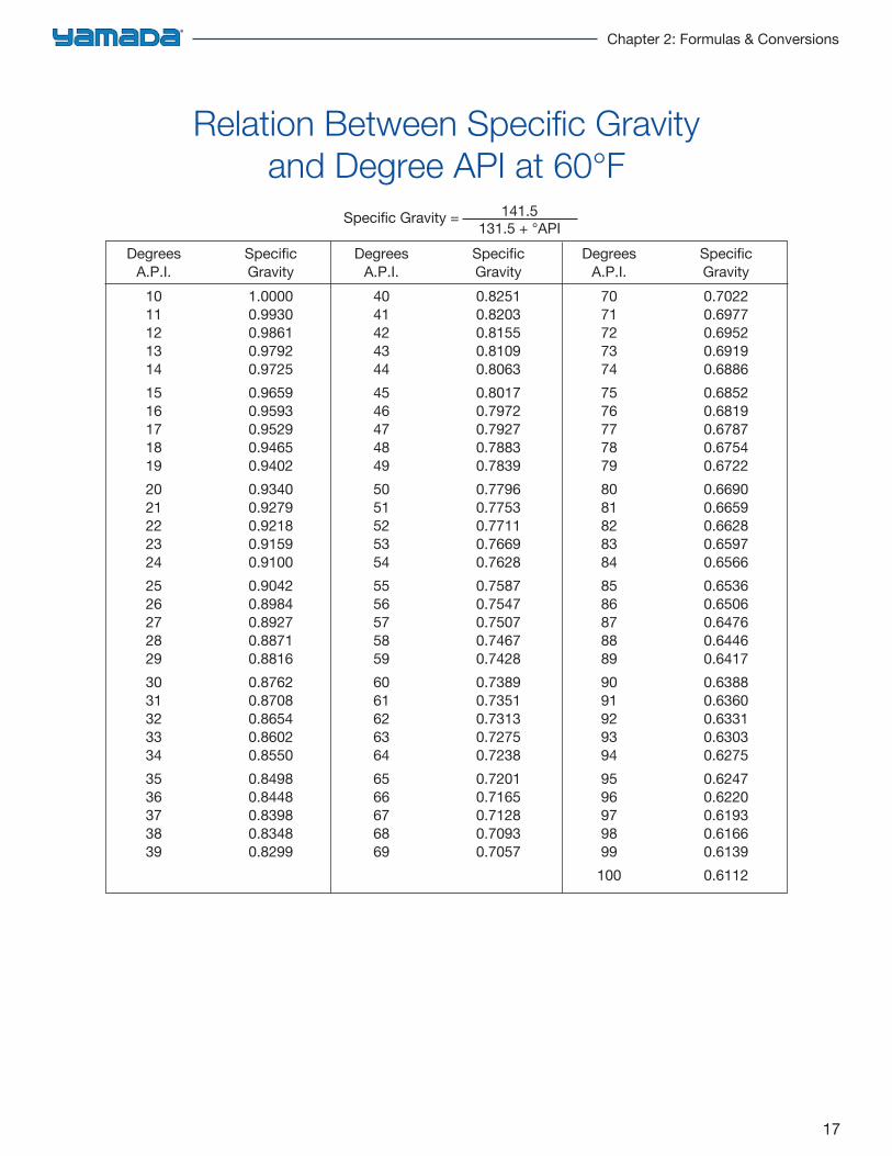
Relation Between Specific Gravity and Degree API at 60°F
Specific Gravity = 141.5131.5 + °API
Degrees Specific A.P.I. Gravity 10 1.0000 11 0.9930 12 0.9861 13 0.9792 14 0.9725 15 0.9659 16 0.9593 17 0.9529 18 0.9465 19 0.9402 20 0.9340 21 0.9279 22 0.9218 23 0.9159 24 0.9100 25 0.9042 26 0.8984 27 0.8927 28 0.8871 29 0.8816 30 0.8762 31 0.8708 32 0.8654 33 0.8602 34 0.8550 35 0.8498 36 0.8448 37 0.8398 38 0.8348 39 0.8299
Degrees Specific A.P.I. Gravity 40 0.8251 41 0.8203 42 0.8155 43 0.8109 44 0.8063 45 0.8017 46 0.7972 47 0.7927 48 0.7883 49 0.7839 50 0.7796 51 0.7753 52 0.7711 53 0.7669 54 0.7628 55 0.7587 56 0.7547 57 0.7507 58 0.7467 59 0.7428 60 0.7389 61 0.7351 62 0.7313 63 0.7275 64 0.7238 65 0.7201 66 0.7165 67 0.7128 68 0.7093 69 0.7057
Degrees Specific A.P.I. Gravity 70 0.7022 71 0.6977 72 0.6952 73 0.6919 74 0.6886 75 0.6852 76 0.6819 77 0.6787 78 0.6754 79 0.6722 80 0.6690 81 0.6659 82 0.6628 83 0.6597 84 0.6566 85 0.6536 86 0.6506 87 0.6476 88 0.6446 89 0.6417 90 0.6388 91 0.6360 92 0.6331 93 0.6303 94 0.6275 95 0.6247 96 0.6220 97 0.6193 98 0.6166 99 0.6139 100 0.6112
18
Engineering Handbook for Diaphragm Pumps
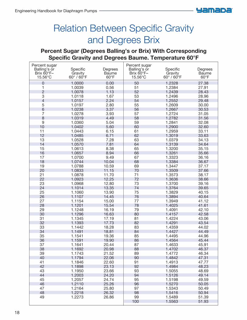
Relation Between Specific Gravity and Degrees Brix
Percent Sugar (Degrees Balling’s or Brix) With CorrespondingSpecific Gravity and Degrees Baume. Temperature 60°F
Percent sugar Balling’s or Specific Degrees Brix 60°F– Gravity Baume 15.56°C 60° / 60°F 60°F 0 1.0000 0.00 1 1.0039 0.56 2 1.0078 1.13 3 1.0118 1.67 4 1.0157 2.24 5 1.0197 2.80 6 1.0238 3.37 7 1.0278 3.93 8 1.0319 4.49 9 1.0360 5.04 10 1.0402 5.60 11 1.0443 6.15 12 1.0485 6.71 13 1.0528 7.28 14 1.0570 7.81 15 1.0613 8.38 16 1.0657 8.94 17 1.0700 9.49 18 1.0744 10.04 19 1.0788 10.59 20 1.0833 11.15 21 1.0878 11.70 22 1.0923 12.25 23 1.0968 12.80 24 1.1014 13.35 25 1.1060 13.90 26 1.1107 14.45 27 1.1154 15.00 28 1.1201 15.54 29 1.1248 16.19 30 1.1296 16.63 31 1.1345 17.19 32 1.1393 17.73 33 1.1442 18.28 34 1.1491 18.81 35 1.1541 19.36 36 1.1591 19.90 37 1.1641 20.44 38 1.1692 20.98 39 1.1743 21.52 40 1.1794 22.06 41 1.1846 22.60 42 1.1898 23.13 43 1.1950 23.66 44 1.2003 24.20 45 1.2057 24.74 46 1.2110 25.26 47 1.2164 25.80 48 1.2218 26.32 49 1.2273 26.86
Percent sugar Balling’s or Specific Degrees Brix 60°F– Gravity Baume 15.56°C 60° / 60°F 60°F 50 1.2328 27.38 51 1.2384 27.91 52 1.2439 28.43 53 1.2496 28.96 54 1.2552 29.48 55 1.2609 30.00 56 1.2667 30.53 57 1.2724 31.05 58 1.2782 31.56 59 1.2841 32.08 60 1.2900 32.60 61 1.2959 33.11 62 1.3019 33.63 63 1.0379 34.13 64 1.3139 34.64 65 1.3200 35.15 66 1.3261 35.66 67 1.3323 36.16 68 1.3384 36.67 69 1.3447 37.17 70 1.3509 37.66 71 1.3573 38.17 72 1.3636 38.66 73 1.3700 39.16 74 1.3764 39.65 75 1.3829 40.15 76 1.3894 40.64 77 1.3949 41.12 78 1.4025 41.61 79 1.4091 42.10 80 1.4157 42.58 81 1.4224 43.06 82 1.4291 43.54 83 1.4359 44.02 84 1.4427 44.49 85 1.4495 44.96 86 1.4564 45.44 87 1.4633 45.91 88 1.4702 46.37 89 1.4772 46.34 90 1.4842 47.31 91 1.4913 47.77 92 1.4984 48.23 93 1.5055 48.69 94 1.5126 49.14 95 1.5198 49.59 96 1.5270 50.05 97 1.5343 50.49 98 1.5416 50.94 99 1.5489 51.39 100 1.5563 51.93
19
Chapter 2: Formulas & Conversions
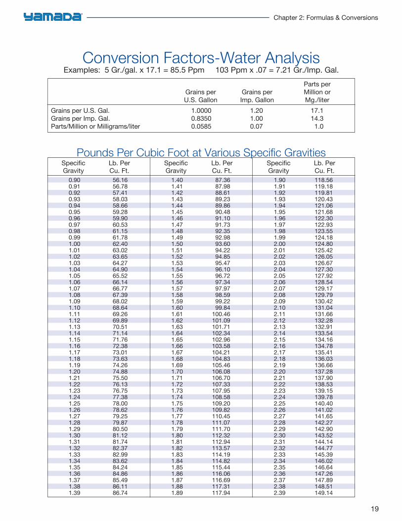
Conversion Factors-Water AnalysisExamples: 5 Gr./gal. x 17.1 = 85.5 Ppm 103 Ppm x .07 = 7.21 Gr./Imp. Gal.
Parts perGrains per Grains per Million orU.S. Gallon Imp. Gallon Mg./liter
Grains per U.S. Gal. 1.0000 1.20 17.1Grains per Imp. Gal. 0.8350 1.00 14.3Parts/Million or Milligrams/liter 0.0585 0.07 1.0
19
Specific Lb. Per Gravity Cu. Ft.
0.90 56.16 0.91 56.78 0.92 57.41 0.93 58.03 0.94 58.66 0.95 59.28 0.96 59.90 0.97 60.53 0.98 61.15 0.99 61.78 1.00 62.40 1.01 63.02 1.02 63.65 1.03 64.27 1.04 64.90 1.05 65.52 1.06 66.14 1.07 66.77 1.08 67.39 1.09 68.02 1.10 68.64 1.11 69.26 1.12 69.89 1.13 70.51 1.14 71.14 1.15 71.76 1.16 72.38 1.17 73.01 1.18 73.63 1.19 74.26 1.20 74.88 1.21 75.50 1.22 76.13 1.23 76.75 1.24 77.38 1.25 78.00 1.26 78.62 1.27 79.25 1.28 79.87 1.29 80.50 1.30 81.12 1.31 81.74 1.32 82.37 1.33 82.99 1.34 83.62 1.35 84.24 1.36 84.86 1.37 85.49 1.38 86.11 1.39 86.74
Specific Lb. Per Gravity Cu. Ft.
1.40 87.36 1.41 87.98 1.42 88.61 1.43 89.23 1.44 89.86 1.45 90.48 1.46 91.10 1.47 91.73 1.48 92.35 1.49 92.98 1.50 93.60 1.51 94.22 1.52 94.85 1.53 95.47 1.54 96.10 1.55 96.72 1.56 97.34 1.57 97.97 1.58 98.59 1.59 99.22 1.60 99.84 1.61 100.46 1.62 101.09 1.63 101.71 1.64 102.34 1.65 102.96 1.66 103.58 1.67 104.21 1.68 104.83 1.69 105.46 1.70 106.08 1.71 106.70 1.72 107.33 1.73 107.95 1.74 108.58 1.75 109.20 1.76 109.82 1.77 110.45 1.78 111.07 1.79 111.70 1.80 112.32 1.81 112.94 1.82 113.57 1.83 114.19 1.84 114.82 1.85 115.44 1.86 116.06 1.87 116.69 1.88 117.31 1.89 117.94
Specific Lb. Per Gravity Cu. Ft. 1.90 118.56 1.91 119.18 1.92 119.81 1.93 120.43 1.94 121.06 1.95 121.68 1.96 122.30 1.97 122.93 1.98 123.55 1.99 124.18 2.00 124.80 2.01 125.42 2.02 126.05 2.03 126.67 2.04 127.30 2.05 127.92 2.06 128.54 2.07 129.17 2.08 129.79 2.09 130.42 2.10 131.04 2.11 131.66 2.12 132.28 2.13 132.91 2.14 133.54 2.15 134.16 2.16 134.78 2.17 135.41 2.18 136.03 2.19 136.66 2.20 137.28 2.21 137.90 2.22 138.53 2.23 139.15 2.24 139.78 2.25 140.40 2.26 141.02 2.27 141.65 2.28 142.27 2.29 142.90 2.30 143.52 2.31 144.14 2.32 144.77 2.33 145.39 2.34 146.02 2.35 146.64 2.36 147.26 2.37 147.89 2.38 148.51 2.39 149.14
Pounds Per Cubic Foot at Various Specific Gravities
20
Engineering Handbook for Diaphragm Pumps
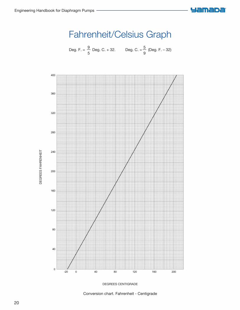
Fahrenheit/Celsius GraphDeg. F. = 9
5 Deg. C. + 32. Deg. C. = 5
9 (Deg. F. – 32)
DEG
REES
FAH
REN
HEI
T
DEGREES CENTIGRADE
Conversion chart. Fahrenheit - Centigrade
21
Chapter 2: Formulas & Conversions
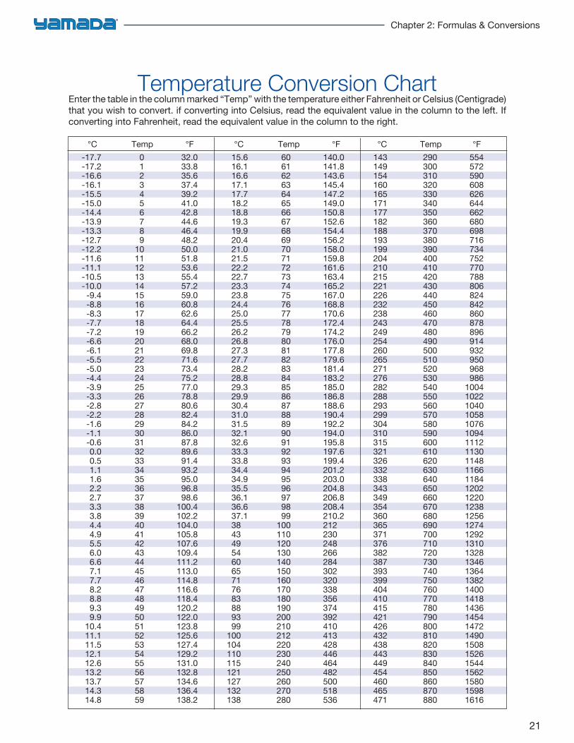
Temperature Conversion ChartEnter the table in the column marked “Temp” with the temperature either Fahrenheit or Celsius (Centigrade) that you wish to convert. if converting into Celsius, read the equivalent value in the column to the left. If converting into Fahrenheit, read the equivalent value in the column to the right.
°C Temp °F -17.7 0 32.0 -17.2 1 33.8 -16.6 2 35.6 -16.1 3 37.4 -15.5 4 39.2 -15.0 5 41.0 -14.4 6 42.8 -13.9 7 44.6 -13.3 8 46.4 -12.7 9 48.2 -12.2 10 50.0 -11.6 11 51.8 -11.1 12 53.6 -10.5 13 55.4 -10.0 14 57.2 -9.4 15 59.0 -8.8 16 60.8 -8.3 17 62.6 -7.7 18 64.4 -7.2 19 66.2 -6.6 20 68.0 -6.1 21 69.8 -5.5 22 71.6 -5.0 23 73.4 -4.4 24 75.2 -3.9 25 77.0 -3.3 26 78.8 -2.8 27 80.6 -2.2 28 82.4 -1.6 29 84.2 -1.1 30 86.0 -0.6 31 87.8 0.0 32 89.6 0.5 33 91.4 1.1 34 93.2 1.6 35 95.0 2.2 36 96.8 2.7 37 98.6 3.3 38 100.4 3.8 39 102.2 4.4 40 104.0 4.9 41 105.8 5.5 42 107.6 6.0 43 109.4 6.6 44 111.2 7.1 45 113.0 7.7 46 114.8 8.2 47 116.6 8.8 48 118.4 9.3 49 120.2 9.9 50 122.0 10.4 51 123.8 11.1 52 125.6 11.5 53 127.4 12.1 54 129.2 12.6 55 131.0 13.2 56 132.8 13.7 57 134.6 14.3 58 136.4 14.8 59 138.2
°C Temp °F 15.6 60 140.0 16.1 61 141.8 16.6 62 143.6 17.1 63 145.4 17.7 64 147.2 18.2 65 149.0 18.8 66 150.8 19.3 67 152.6 19.9 68 154.4 20.4 69 156.2 21.0 70 158.0 21.5 71 159.8 22.2 72 161.6 22.7 73 163.4 23.3 74 165.2 23.8 75 167.0 24.4 76 168.8 25.0 77 170.6 25.5 78 172.4 26.2 79 174.2 26.8 80 176.0 27.3 81 177.8 27.7 82 179.6 28.2 83 181.4 28.8 84 183.2 29.3 85 185.0 29.9 86 186.8 30.4 87 188.6 31.0 88 190.4 31.5 89 192.2 32.1 90 194.0 32.6 91 195.8 33.3 92 197.6 33.8 93 199.4 34.4 94 201.2 34.9 95 203.0 35.5 96 204.8 36.1 97 206.8 36.6 98 208.4 37.1 99 210.2 38 100 212 43 110 230 49 120 248 54 130 266 60 140 284 65 150 302 71 160 320 76 170 338 83 180 356 88 190 374 93 200 392 99 210 410 100 212 413 104 220 428 110 230 446 115 240 464 121 250 482 127 260 500 132 270 518 138 280 536
°C Temp °F 143 290 554 149 300 572 154 310 590 160 320 608 165 330 626 171 340 644 177 350 662 182 360 680 188 370 698 193 380 716 199 390 734 204 400 752 210 410 770 215 420 788 221 430 806 226 440 824 232 450 842 238 460 860 243 470 878 249 480 896 254 490 914 260 500 932 265 510 950 271 520 968 276 530 986 282 540 1004 288 550 1022 293 560 1040 299 570 1058 304 580 1076 310 590 1094 315 600 1112 321 610 1130 326 620 1148 332 630 1166 338 640 1184 343 650 1202 349 660 1220 354 670 1238 360 680 1256 365 690 1274 371 700 1292 376 710 1310 382 720 1328 387 730 1346 393 740 1364 399 750 1382 404 760 1400 410 770 1418 415 780 1436 421 790 1454 426 800 1472 432 810 1490 438 820 1508 443 830 1526 449 840 1544 454 850 1562 460 860 1580 465 870 1598 471 880 1616
22
Engineering Handbook for Diaphragm Pumps
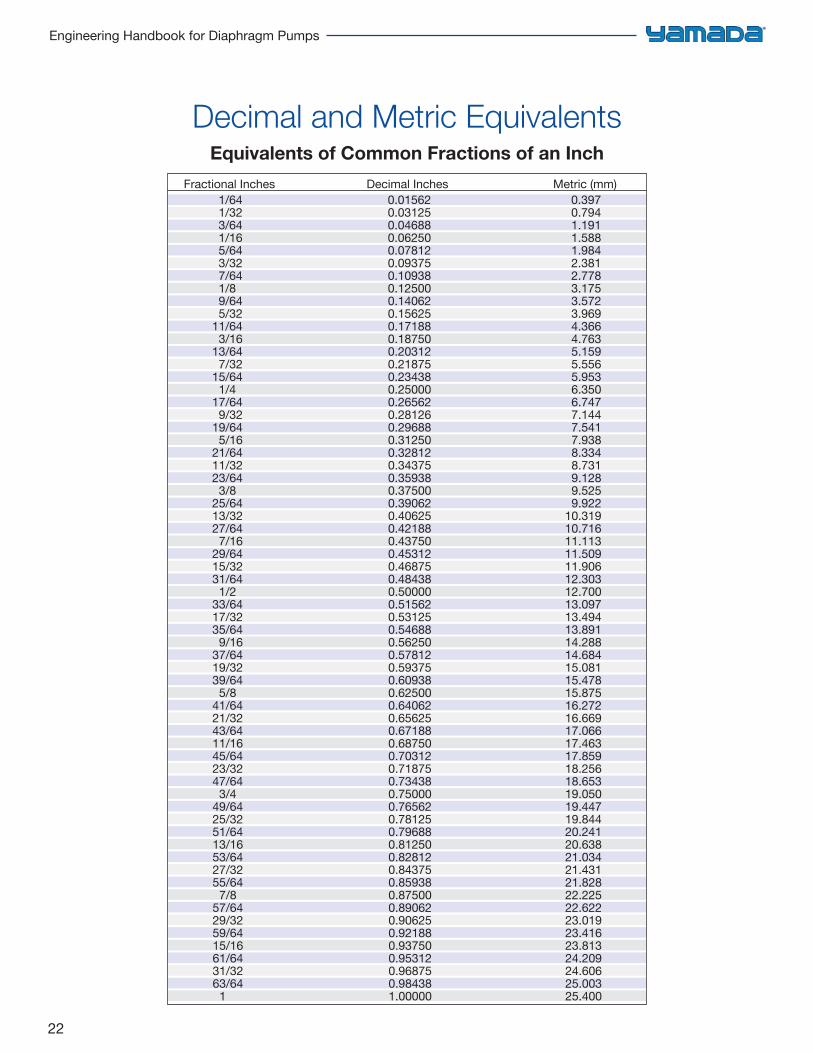
Decimal and Metric EquivalentsEquivalents of Common Fractions of an Inch
Fractional Inches Decimal Inches Metric (mm) 1/64 0.01562 0.397 1/32 0.03125 0.794 3/64 0.04688 1.191 1/16 0.06250 1.588 5/64 0.07812 1.984 3/32 0.09375 2.381 7/64 0.10938 2.778 1/8 0.12500 3.175 9/64 0.14062 3.572 5/32 0.15625 3.969 11/64 0.17188 4.366 3/16 0.18750 4.763 13/64 0.20312 5.159 7/32 0.21875 5.556 15/64 0.23438 5.953 1/4 0.25000 6.350 17/64 0.26562 6.747 9/32 0.28126 7.144 19/64 0.29688 7.541 5/16 0.31250 7.938 21/64 0.32812 8.334 11/32 0.34375 8.731 23/64 0.35938 9.128 3/8 0.37500 9.525 25/64 0.39062 9.922 13/32 0.40625 10.319 27/64 0.42188 10.716 7/16 0.43750 11.113 29/64 0.45312 11.509 15/32 0.46875 11.906 31/64 0.48438 12.303 1/2 0.50000 12.700 33/64 0.51562 13.097 17/32 0.53125 13.494 35/64 0.54688 13.891 9/16 0.56250 14.288 37/64 0.57812 14.684 19/32 0.59375 15.081 39/64 0.60938 15.478 5/8 0.62500 15.875 41/64 0.64062 16.272 21/32 0.65625 16.669 43/64 0.67188 17.066 11/16 0.68750 17.463 45/64 0.70312 17.859 23/32 0.71875 18.256 47/64 0.73438 18.653 3/4 0.75000 19.050 49/64 0.76562 19.447 25/32 0.78125 19.844 51/64 0.79688 20.241 13/16 0.81250 20.638 53/64 0.82812 21.034 27/32 0.84375 21.431 55/64 0.85938 21.828 7/8 0.87500 22.225 57/64 0.89062 22.622 29/32 0.90625 23.019 59/64 0.92188 23.416 15/16 0.93750 23.813 61/64 0.95312 24.209 31/32 0.96875 24.606 63/64 0.98438 25.003 1 1.00000 25.400
23
Chapter 3: Friction Loss
Friction Loss in Iron Pipe 24
Friction Loss Correction For Fittings 28
Friction in Other Types of Pipe 29
Relative Roughness Factors for New Clean Pipes 30
Friction Loss as Affected by Aging of Pipe 31
Friction Loss of Water Per 100 Feet of Flexible Pipe 32
Friction Loss
24
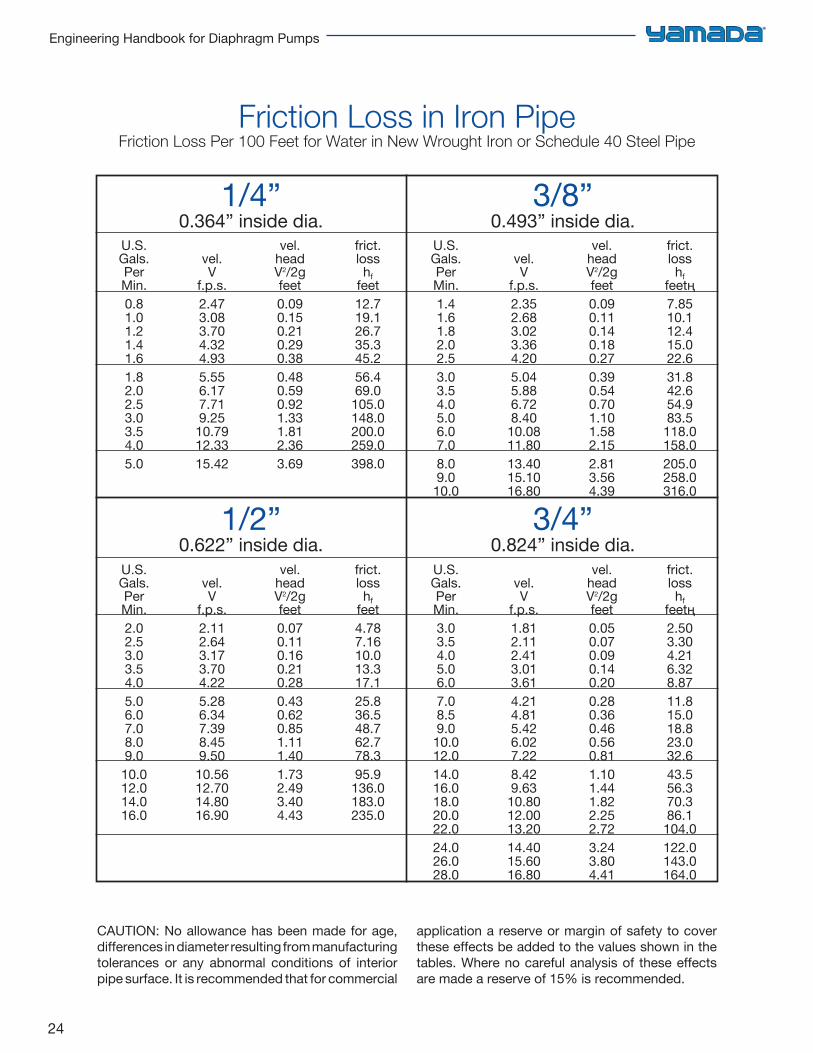
Engineering Handbook for Diaphragm Pumps
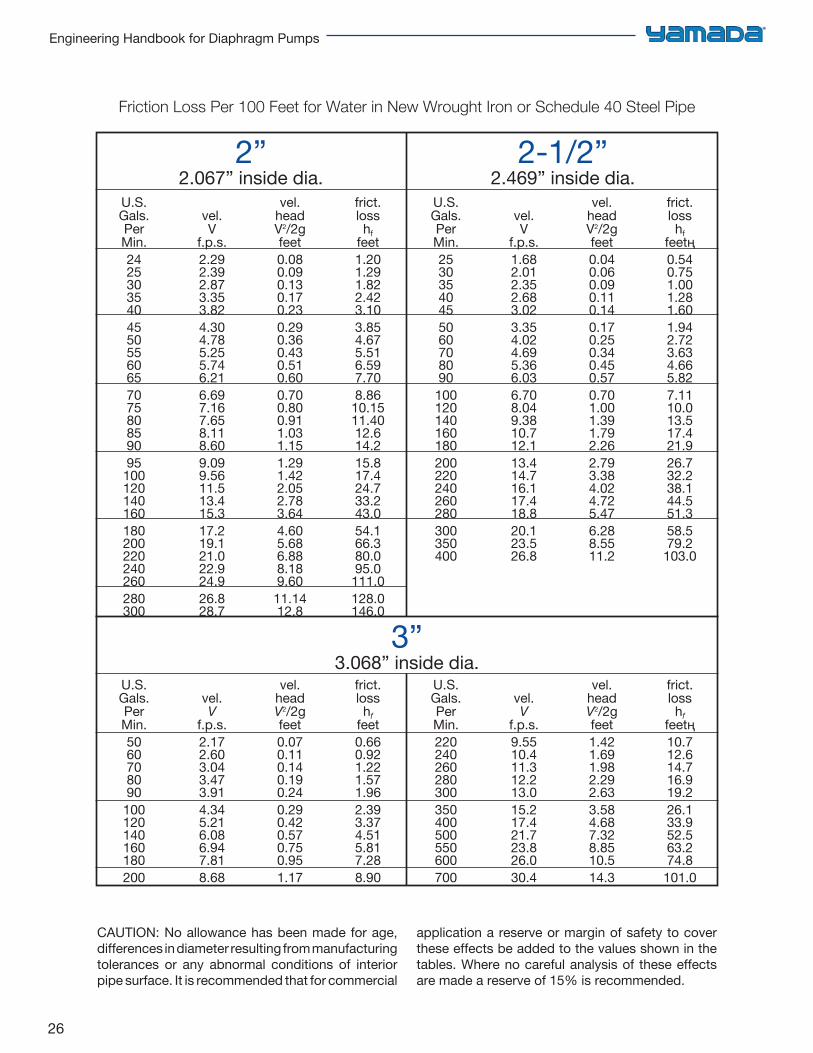
Friction Loss in Iron PipeFriction Loss Per 100 Feet for Water in New Wrought Iron or Schedule 40 Steel Pipe
CAUTION: No allowance has been made for age, differences in diameter resulting from manufacturing tolerances or any abnormal conditions of interior pipe surface. It is recommended that for commercial
application a reserve or margin of safety to cover these effects be added to the values shown in the tables. Where no careful analysis of these effects are made a reserve of 15% is recommended.
1/4”0.364” inside dia.
3/8”0.493” inside dia.
1/2”0.622” inside dia.
3/4”0.824” inside dia.
U.S.Gals.PerMin.0.81.01.21.41.61.82.02.53.03.54.05.0
vel.V
f.p.s.2.473.083.704.324.935.556.177.719.2510.7912.3315.42
vel.headV2/2gfeet0.090.150.210.290.380.480.590.921.331.812.363.69
frict.losshf
feet12.719.126.735.345.256.469.0105.0148.0200.0259.0398.0
U.S.Gals.PerMin.1.41.61.82.02.53.03.54.05.06.07.08.09.010.0
vel.V
f.p.s.2.352.683.023.364.205.045.886.728.4010.0811.8013.4015.1016.80
vel.headV2/2gfeet0.090.110.140.180.270.390.540.701.101.582.152.813.564.39
frict.losshf
feetң7.8510.112.415.022.631.842.654.983.5118.0158.0205.0258.0316.0
U.S.Gals.PerMin.2.02.53.03.54.05.06.07.08.09.010.012.014.016.0
vel.V
f.p.s.2.112.643.173.704.225.286.347.398.459.5010.5612.7014.8016.90
vel.headV2/2gfeet0.070.110.160.210.280.430.620.851.111.401.732.493.404.43
frict.losshf
feet4.787.1610.013.317.125.836.548.762.778.395.9136.0183.0235.0
U.S.Gals.PerMin.3.03.54.05.06.07.08.59.010.012.014.016.018.020.022.024.026.028.0
vel.V
f.p.s.1.812.112.413.013.614.214.815.426.027.228.429.6310.8012.0013.2014.4015.6016.80
vel.headV2/2gfeet0.050.070.090.140.200.280.360.460.560.811.101.441.822.252.723.243.804.41
frict.losshf
feetң2.503.304.216.328.8711.815.018.823.032.643.556.370.386.1104.0122.0143.0164.0
25
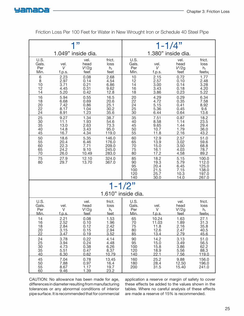
Chapter 3: Friction Loss
Friction Loss Per 100 Feet for Water in New Wrought Iron or Schedule 40 Steel Pipe
CAUTION: No allowance has been made for age, differences in diameter resulting from manufacturing tolerances or any abnormal conditions of interior pipe surface. It is recommended that for commercial
application a reserve or margin of safety to cover these effects be added to the values shown in the tables. Where no careful analysis of these effects are made a reserve of 15% is recommended.
1”1.049” inside dia.
1-1/4”1.380” inside dia.
U.S.Gals.PerMin.
681012141618202224253035404550556065707580
vel.V
f.p.s.2.232.973.714.455.205.946.687.428.178.919.2711.113.014.816.718.620.422.324.226.027.929.7
vel.headV2/2gfeet0.080.140.210.310.420.550.690.861.041.231.341.932.633.434.345.356.467.719.1010.4912.1013.70
frict.losshf
feet2.684.546.869.6212.816.520.625.130.235.638.754.673.395.0119.0146.0176.0209.0245.0283.0324.0367.0
U.S.Gals.PerMin.1012141618202224253035404550556065707580859095100120140
vel.V
f.p.s.2.152.573.003.433.864.294.725.155.366.447.518.589.6510.711.812.913.915.016.117.218.219.320.421.525.730.0
vel.headV2/2gfeet0.720.100.140.180.230.290.350.410.450.640.871.141.441.792.162.573.023.504.034.585.155.796.457.1510.314.0
frict.losshf
feetң1.772.483.284.205.226.347.588.929.613.618.223.529.436.043.251.059.668.878.789.2100.0112.0125.0138.0197.0267.0
U.S.Gals.PerMin.1416182022242530354045505560
vel.V
f.p.s.2.212.522.843.153.473.783.944.735.516.307.047.888.679.46
vel.headV2/2gfeet0.080.100.120.150.190.220.240.380.470.620.780.971.171.39
frict.losshf
feet1.531.962.422.943.524.144.486.268.3710.7913.4516.419.723.2
U.S.Gals.PerMin.65707580859095100120140160180200
vel.V
f.p.s.10.2411.0311.812.613.414.215.015.818.922.125.228.431.5
vel.headV2/2gfeet1.631.892.162.472.793.133.493.865.567.569.8812.5015.40
frict.losshf
feetң27.131.335.840.545.651.056.562.288.3119.0156.0196.0241.0
1-1/2”1.610” inside dia.
26
Engineering Handbook for Diaphragm Pumps
Friction Loss Per 100 Feet for Water in New Wrought Iron or Schedule 40 Steel Pipe
CAUTION: No allowance has been made for age, differences in diameter resulting from manufacturing tolerances or any abnormal conditions of interior pipe surface. It is recommended that for commercial
application a reserve or margin of safety to cover these effects be added to the values shown in the tables. Where no careful analysis of these effects are made a reserve of 15% is recommended.
2”2.067” inside dia.
2-1/2”2.469” inside dia.
U.S.Gals.PerMin.24253035404550556065707580859095100120140160180200220240260280300
vel.V
f.p.s.2.292.392.873.353.824.304.785.255.746.216.697.167.658.118.609.099.5611.513.415.317.219.121.022.924.926.828.7
vel.headV2/2gfeet0.080.090.130.170.230.290.360.430.510.600.700.800.911.031.151.291.422.052.783.644.605.686.888.189.6011.1412.8
frict.losshf
feet1.201.291.822.423.103.854.675.516.597.708.8610.1511.4012.614.215.817.424.733.243.054.166.380.095.0111.0128.0146.0
U.S.Gals.PerMin.25303540455060708090100120140160180200220240260280300350400
vel.V
f.p.s.1.682.012.352.683.023.354.024.695.366.036.708.049.3810.712.113.414.716.117.418.820.123.526.8
vel.headV2/2gfeet0.040.060.090.110.140.170.250.340.450.570.701.001.391.792.262.793.384.024.725.476.288.5511.2
frict.losshf
feetң0.540.751.001.281.601.942.723.634.665.827.1110.013.517.421.926.732.238.144.551.358.579.2103.0
U.S.Gals.PerMin.5060708090100120140160180200
vel.V
f.p.s.2.172.603.043.473.914.345.216.086.947.818.68
vel.headV2/2gfeet0.070.110.140.190.240.290.420.570.750.951.17
frict.losshf
feet0.660.921.221.571.962.393.374.515.817.288.90
U.S.Gals.PerMin.220240260280300350400500550600700
vel.V
f.p.s.9.5510.411.312.213.015.217.421.723.826.030.4
vel.headV2/2gfeet1.421.691.982.292.633.584.687.328.8510.514.3
frict.losshf
feetң10.712.614.716.919.226.133.952.563.274.8101.0
3”3.068” inside dia.
27
Chapter 3: Friction Loss
Friction Loss Per 100 Feet for Water in New Wrought Iron or Schedule 40 Steel Pipe
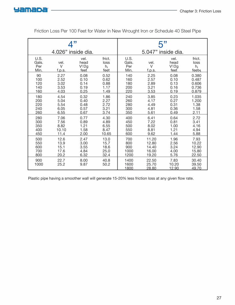
Plastic pipe having a smoother wall will generate 15-20% less friction loss at any given flow rate.
4”4.026” inside dia.
5”5.047” inside dia.
U.S.Gals.PerMin.901001201401601802002202402602803003504004505005506007008009001000
vel.V
f.p.s.2.272.523.023.534.034.545.045.546.056.557.067.568.8210.1011.412.613.915.117.620.222.725.2
vel.headV2/2gfeet0.080.100.140.190.250.320.400.480.570.670.770.891.211.582.002.473.003.554.846.328.009.87
frict.losshf
feet0.520.620.881.171.491.862.272.723.213.744.304.896.558.4710.6513.015.718.625.032.440.850.2
U.S.Gals.PerMin.14016018020022024026028030035040045050055060070080090010001200140016001800
vel.V
f.p.s.2.252.572.893.213.533.854.174.494.815.616.417.228.028.819.6211.2012.8014.4016.0019.2022.5025.7028.80
vel.headV2/2gfeet0.080.100.130.160.190.230.270.310.360.490.640.811.001.211.441.962.563.244.005.767.8310.2012.90
frict.losshf
feetң0.3800.4870.6060.7360.8791.0351.2001.381.582.112.723.414.164.945.887.9310.2212.9015.8022.5030.4039.5049.70
28
Engineering Handbook for Diaphragm Pumps
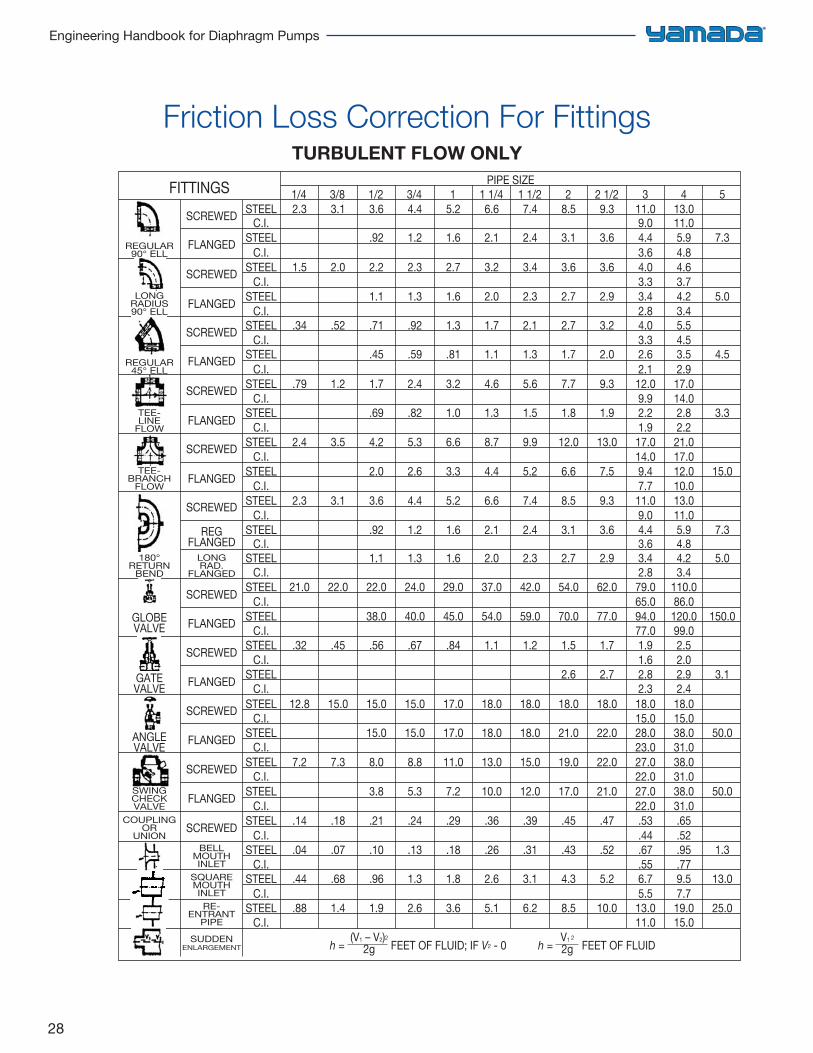
Friction Loss Correction For Fittings TURBULENT FLOW ONLY
PIPE SIZE1/4 3/8 1/2 3/4 1 1 1/4 1 1/2 2 2 1/2 3 4 5
STEEL 2.3 3.1 3.6 4.4 5.2 6.6 7.4 8.5 9.3 11.0 13.0C.I. 9.0 11.0
C.I. 3.6 4.8
C.I. 3.3 3.7
C.I. 2.8 3.4
C.I. 3.3 4.5
C.I. 2.1 2.9
C.I. 9.9 14.0
C.I. 1.9 2.2
C.I. 14.0 17.0
C.I. 7.7 10.0
C.I. 9.0 11.0
C.I. 3.6 4.8
C.I. 2.8 3.4
C.I. 65.0 86.0
C.I. 77.0 99.0
C.I. 1.6 2.0
C.I. 2.3 2.4
C.I. 15.0 15.0
C.I. 23.0 31.0
C.I. 22.0 31.0
C.I. 22.0 31.0
C.I. .44 .52
C.I. .55 .77
C.I. 5.5 7.7
C.I. 11.0 15.0
STEEL .92 1.2 1.6 2.1 2.4 3.1 3.6 4.4 5.9 7.3
STEEL 1.5 2.0 2.2 2.3 2.7 3.2 3.4 3.6 3.6 4.0 4.6
STEEL 1.1 1.3 1.6 2.0 2.3 2.7 2.9 3.4 4.2 5.0
STEEL .34 .52 .71 .92 1.3 1.7 2.1 2.7 3.2 4.0 5.5
STEEL .69 .82 1.0 1.3 1.5 1.8 1.9 2.2 2.8 3.3
STEEL 2.4 3.5 4.2 5.3 6.6 8.7 9.9 12.0 13.0 17.0 21.0
STEEL 2.0 2.6 3.3 4.4 5.2 6.6 7.5 9.4 12.0 15.0
STEEL 2.3 3.1 3.6 4.4 5.2 6.6 7.4 8.5 9.3 11.0 13.0
STEEL .92 1.2 1.6 2.1 2.4 3.1 3.6 4.4 5.9 7.3
STEEL 1.1 1.3 1.6 2.0 2.3 2.7 2.9 3.4 4.2 5.0
STEEL 21.0 22.0 22.0 24.0 29.0 37.0 42.0 54.0 62.0 79.0 110.0
STEEL 38.0 40.0 45.0 54.0 59.0 70.0 77.0 94.0 120.0 150.0
STEEL .32 .45 .56 .67 .84 1.1 1.2 1.5 1.7 1.9 2.5
STEEL 2.6 2.7 2.8 2.9 3.1
STEEL 12.8 15.0 15.0 15.0 17.0 18.0 18.0 18.0 18.0 18.0 18.0
STEEL 15.0 15.0 17.0 18.0 18.0 21.0 22.0 28.0 38.0 50.0
STEEL 7.2 7.3 8.0 8.8 11.0 13.0 15.0 19.0 22.0 27.0 38.0
STEEL 3.8 5.3 7.2 10.0 12.0 17.0 21.0 27.0 38.0 50.0
STEEL .14 .18 .21 .24 .29 .36 .39 .45 .47 .53 .65
STEEL .04 .07 .10 .13 .18 .26 .31 .43 .52 .67 .95 1.3
STEEL .44 .68 .96 1.3 1.8 2.6 3.1 4.3 5.2 6.7 9.5 13.0
STEEL .88 1.4 1.9 2.6 3.6 5.1 6.2 8.5 10.0 13.0 19.0 25.0
STEEL .79 1.2 1.7 2.4 3.2 4.6 5.6 7.7 9.3 12.0 17.0
STEEL .45 .59 .81 1.1 1.3 1.7 2.0 2.6 3.5 4.5
SCREWED
FITTINGS
SCREWED
SCREWED
SCREWED
SCREWED
SCREWED
SCREWED
SCREWED
SCREWED
SCREWED
SCREWED
REGFLANGED
ANGLEVALVE
h = FEET OF FLUID; IF V2 - 0 h = FEET OF FLUID
GATEVALVE
GLOBEVALVE
FLANGED
FLANGED
FLANGED
FLANGED
FLANGED
FLANGED
FLANGED
FLANGED
FLANGED
LONGRAD.
FLANGED
BELLMOUTHINLET
COUPLINGOR
UNION
SWINGCHECKVALVE
SQUAREMOUTHINLETRE-
ENTRANTPIPE
SUDDENENLARGEMENT
180°RETURN
BEND
TEE-BRANCH
FLOW
TEE-LINE
FLOW
LONGRADIUS90° ELL
REGULAR45° ELL
REGULAR90° ELL
(V1 – V2)2
2gV1 2
2g
29
Chapter 3: Friction Loss
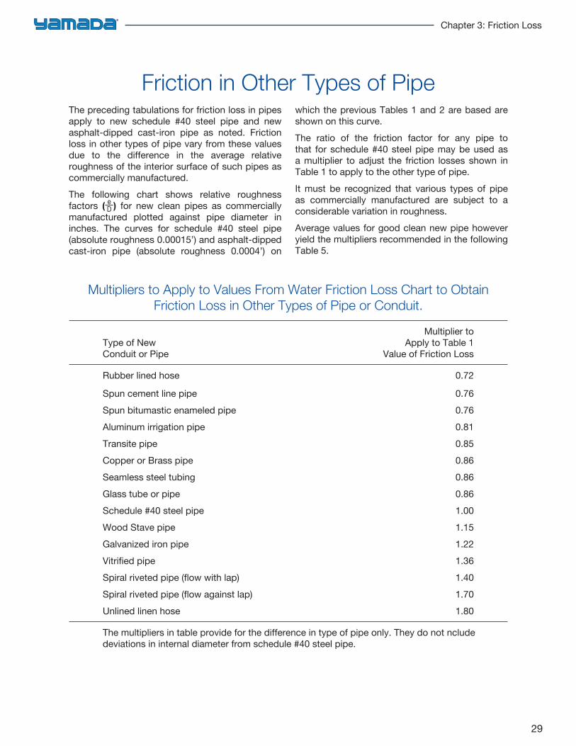
Friction in Other Types of Pipe
Multipliers to Apply to Values From Water Friction Loss Chart to Obtain Friction Loss in Other Types of Pipe or Conduit.
Multiplier toType of New Apply to Table 1Conduit or Pipe Value of Friction Loss
Rubber lined hose 0.72
Spun cement line pipe 0.76Spun bitumastic enameled pipe 0.76Aluminum irrigation pipe 0.81Transite pipe 0.85Copper or Brass pipe 0.86Seamless steel tubing 0.86Glass tube or pipe 0.86Schedule #40 steel pipe 1.00Wood Stave pipe 1.15Galvanized iron pipe 1.22Vitrified pipe 1.36Spiral riveted pipe (flow with lap) 1.40Spiral riveted pipe (flow against lap) 1.70Unlined linen hose 1.80
The multipliers in table provide for the difference in type of pipe only. They do not nclude deviations in internal diameter from schedule #40 steel pipe.
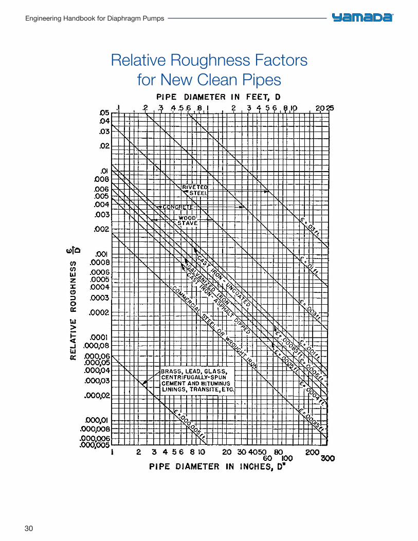
The preceding tabulations for friction loss in pipes apply to new schedule #40 steel pipe and new asphalt-dipped cast-iron pipe as noted. Friction loss in other types of pipe vary from these values due to the difference in the average relative roughness of the interior surface of such pipes as commercially manufactured.The following chart shows relative roughness factors ( ) for new clean pipes as commercially manufactured plotted against pipe diameter in inches. The curves for schedule #40 steel pipe (absolute roughness 0.00015’) and asphalt-dipped cast-iron pipe (absolute roughness 0.0004’) on
which the previous Tables 1 and 2 are based are shown on this curve.The ratio of the friction factor for any pipe to that for schedule #40 steel pipe may be used as a multiplier to adjust the friction losses shown in Table 1 to apply to the other type of pipe.It must be recognized that various types of pipe as commercially manufactured are subject to a considerable variation in roughness.Average values for good clean new pipe however yield the multipliers recommended in the following Table 5.
eD
30
Engineering Handbook for Diaphragm Pumps
Relative Roughness Factors for New Clean Pipes
31
Chapter 3: Friction Loss
Friction Loss as Affected by Aging of Pipe
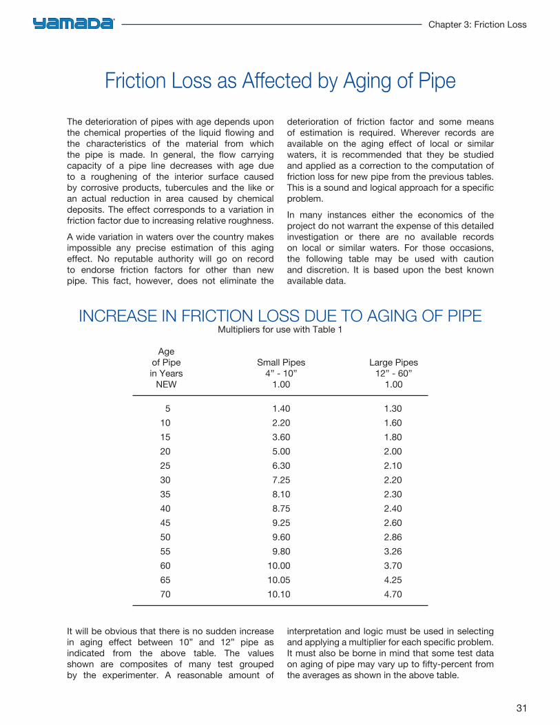
INCREASE IN FRICTION LOSS DUE TO AGING OF PIPEMultipliers for use with Table 1
Ageof Pipe Small Pipes Large Pipesin Years 4” - 10” 12” - 60”
NEW 1.00 1.00
5 1.40 1.3010 2.20 1.6015 3.60 1.8020 5.00 2.0025 6.30 2.1030 7.25 2.2035 8.10 2.3040 8.75 2.4045 9.25 2.6050 9.60 2.8655 9.80 3.2660 10.00 3.7065 10.05 4.2570 10.10 4.70
The deterioration of pipes with age depends upon the chemical properties of the liquid flowing and the characteristics of the material from which the pipe is made. In general, the flow carrying capacity of a pipe line decreases with age due to a roughening of the interior surface caused by corrosive products, tubercules and the like or an actual reduction in area caused by chemical deposits. The effect corresponds to a variation in friction factor due to increasing relative roughness.A wide variation in waters over the country makes impossible any precise estimation of this aging effect. No reputable authority will go on record to endorse friction factors for other than new pipe. This fact, however, does not eliminate the
deterioration of friction factor and some means of estimation is required. Wherever records are available on the aging effect of local or similar waters, it is recommended that they be studied and applied as a correction to the computation of friction loss for new pipe from the previous tables. This is a sound and logical approach for a specific problem.In many instances either the economics of the project do not warrant the expense of this detailed investigation or there are no available records on local or similar waters. For those occasions, the following table may be used with caution and discretion. It is based upon the best known available data.
It will be obvious that there is no sudden increase in aging effect between 10” and 12” pipe as indicated from the above table. The values shown are composites of many test grouped by the experimenter. A reasonable amount of
interpretation and logic must be used in selecting and applying a multiplier for each specific problem. It must also be borne in mind that some test data on aging of pipe may vary up to fifty-percent from the averages as shown in the above table.
32
Engineering Handbook for Diaphragm Pumps
SIZ
E 1/
2”
3/4”
1”
1
1/4”
1
1/2”
2”
3”
4”
GPM 1 2 3 4 5 6 8 10 15 20 25 30 35 40 45 50 60 70 80 90 10
0
Hea
din Feet
1.50
5.08
10.5
1
17.8
1
26.0
1
36.0
1
61.0
0
92.1
5
PSI
.65
2.20
4.55
7.71
11.2
6
15.5
9
26.4
1
39.8
9
Hea
din Feet
.32
1.13
2.40
3.81
5.61
7.51
12.0
1
18.3
2
38.8
3
PSI
.14
.49
1.04
1.65
2.43
3.25
5.20
7.93
16.8
1
Hea
din Feet
.09
.30
.60
1.02
1.43
1.94
3.19
4.90
10.1
2
16.5
2
PSI
.04
.13
.26
.44
.62
.84
1.38
2.12
4.38
7.15
Hea
din Feet
.09
.18
.32
.46
.65
1.04
1.59
3.30
5.50
8.11
10.8
1
14.0
2
PSI
.04
.08
.14
.20
.28
.45
.69
1.43
2.38
3.51
4.68
6.07
Hea
din Feet
.09
.16
.23
.30
.51
.76
1.55
2.54
3.81
5.20
6.61
8.92
10.1
2
11.9
2
PSI
.04
.07
.10
.13
.22
.33
.67
1.10
1.65
2.25
2.86
3.86
4.38
5.16
Hea
din Feet
.09
.14
.23
.49
.83
1.22
1.69
2.19
2.80
3.40
4.09
5.71
7.30
9.22
11.2
0
13.9
1
PSI
.04
.06
.10
.21
.36
.53
.73
.95
1.21
1.47
1.77
2.47
3.16
3.99
4.85
6.02
Hea
din Feet
.12
.18
.25
.32
.42
.53
.85
1.11
1.41
1.80
2.19
3.30
PSI
.05
.08
.11
.14
.18
.23
.37
.48
.61
.78
.95
1.43
Hea
din Feet
.09
.12
.14
.16
.23
.30
.37
.46
.55
.88
PSI
.04
.05
.06
.07
.10
.13
.16
.20
.24
.38
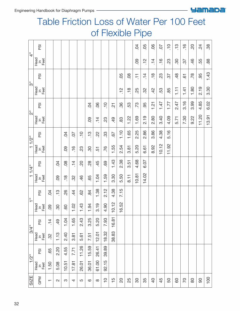
Table Friction Loss of Water Per 100 Feet of Flexible Pipe
33
Chapter 4: Viscous Fluids & Slurries
Viscous Fluid Behavior 34
Shear Rate Information 35
Viscosity Derate/Limitation 36
Viscosity & Specific Gravity of Common Liquids 37
Pump Applications Guide 40
Viscosity Conversion Table 47
Friction Loss in Head For Viscous Liquids 48
Pumping Slurry 50
Mesh Chart 51
Handling Abrasives 51
Specific Gravity 52
Viscous Fluids
34
Engineering Handbook for Diaphragm Pumps
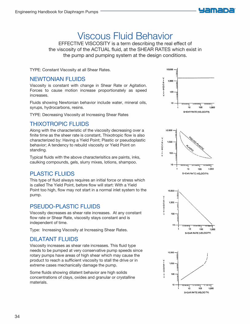
Viscous Fluid BehaviorEFFECTIVE VISCOSITY is a term describing the real effect of
the viscosity of the ACTUAL fluid, at the SHEAR RATES which exist in the pump and pumping system at the design conditions.
TYPE: Constant Viscosity at all Shear Rates.
NEWTONIAN FLUIDSViscosity is constant with change in Shear Rate or Agitation. Forces to cause motion increase proportionately as speed increases. Fluids showing Newtonian behavior include water, mineral oils, syrups, hydrocarbons, resins.TYPE: Decreasing Viscosity at Increasing Shear Rates
THIXOTROPIC FLUIDSAlong with the characteristic of the viscosity decreasing over a finite time as the sheer rate is constant, Thixotropic flow is also characterized by: Having a Yield Point; Plastic or pseudoplastic behavior; A tendency to rebuild viscosity or Yield Point on standing.Typical fluids with the above characterisitics are paints, inks, caulking compounds, gels, slurry mixes, lotions, shampoo.
PLASTIC FLUIDSThis type of fluid always requires an initial force or stress which is called The Yield Point, before flow will start: With a Yield Point too high, flow may not start in a normal inlet system to the pump.
PSEUDO-PLASTIC FLUIDSViscosity decreases as shear rate increases. At any constant flow rate or Shear Rate, viscosity stays constant and is independent of time.Type: Increasing Viscosity at Increasing Shear Rates.
DILATANT FLUIDSViscosity increases as shear rate increases. This fluid type needs to be pumped at very conservative pump speeds since rotary pumps have areas of high shear which may cause the product to reach a sufficient viscosity to stall the drive or in extreme cases mechanically damage the pump.Some fluids showing dilatent behavior are high solids concentrations of clays, oxides and granular or crystalline materials.
35
Chapter 4: Viscous Fluids & Slurries
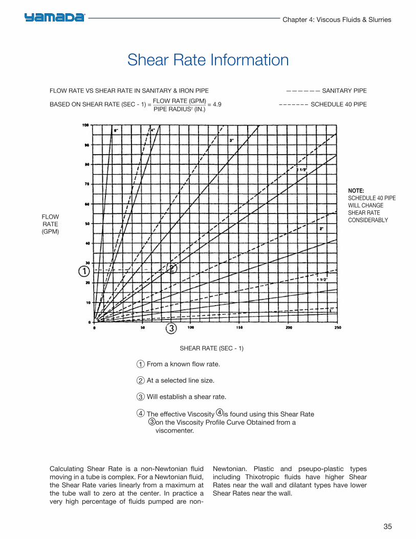
Calculating Shear Rate is a non-Newtonian fluid moving in a tube is complex. For a Newtonian fluid, the Shear Rate varies linearly from a maximum at the tube wall to zero at the center. In practice a very high percentage of fluids pumped are non-
Newtonian. Plastic and pseupo-plastic types including Thixotropic fluids have higher Shear Rates near the wall and dilatant types have lower Shear Rates near the wall.
4
3
2
1
FLOW RATE VS SHEAR RATE IN SANITARY & IRON PIPE —————— SANITARY PIPE
BASED ON SHEAR RATE (SEC - 1) = = 4.9 – – – – – – – SCHEDULE 40 PIPEFLOW RATE (GPM)PIPE RADIUS2 (IN.)
FLOWRATE(GPM)
SHEAR RATE (SEC - 1)
NOTE:SCHEDULE 40 PIPE WILL CHANGE SHEAR RATECONSIDERABLY
Shear Rate Information
From a known fl ow rate.
At a selected line size.
Will establish a shear rate.
The eff ective Viscosity is found using this Shear Rate on the Viscosity Profi le Curve Obtained from a viscomenter.
4
3
36
Engineering Handbook for Diaphragm Pumps
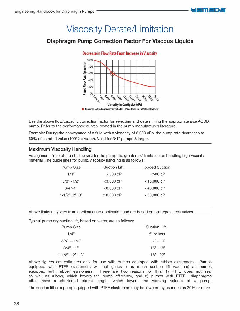
Diaphragm Pump Correction Factor For Viscous Liquids
Viscosity Derate/Limitation
Use the above flow/capacity correction factor for selecting and determining the appropriate size AODD pump. Refer to the performance curves located in the pump manufactures literature.Example: During the conveyance of a fluid with a viscosity of 6,000 cPs, the pump rate decreases to 60% of its rated value (100% = water). Valid for 3/4” pumps & larger.
Maximum Viscosity HandlingAs a general “rule of thumb” the smaller the pump the greater its’ limitation on handling high vicosity material. The guide lines for pump/viscosity handling is as follows:
Pump Size Suction Lift Flooded Suction1/4” <500 cP <500 cP
3/8” -1/2” <3,000 cP <15,000 cP3/4”-1” <8,000 cP <40,000 cP
1-1/2”, 2”, 3” <10,000 cP <50,000 cP
Above limits may vary from application to application and are based on ball type check valves.
Typical pump dry suction lift, based on water, are as follows:Pump Size Suction Lift
1/4” 5’ or less3/8” —1/2” 7’ - 10’
3/4”—1” 15’ - 18’ 1-1/2”—2”—3” 18’ - 22’
Above figures are estimates only for use with pumps equipped with rubber elastomers. Pumps equipped with PTFE elastomers will not generate as much suction lift (vacuum) as pumps equipped with rubber elastomers. There are two reasons for this; 1) PTFE does not seal as well as rubber, which lowers the pump efficiency, and 2) pumps with PTFE diaphragms often have a shortened stroke length, which lowers the working volume of a pump. The suction lift of a pump equipped with PTFE elastomers may be lowered by as much as 20% or more.
37
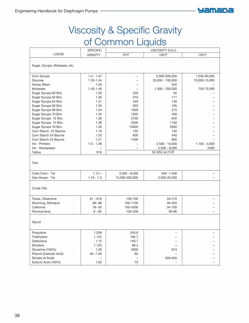
Chapter 4: Viscous Fluids & Slurries
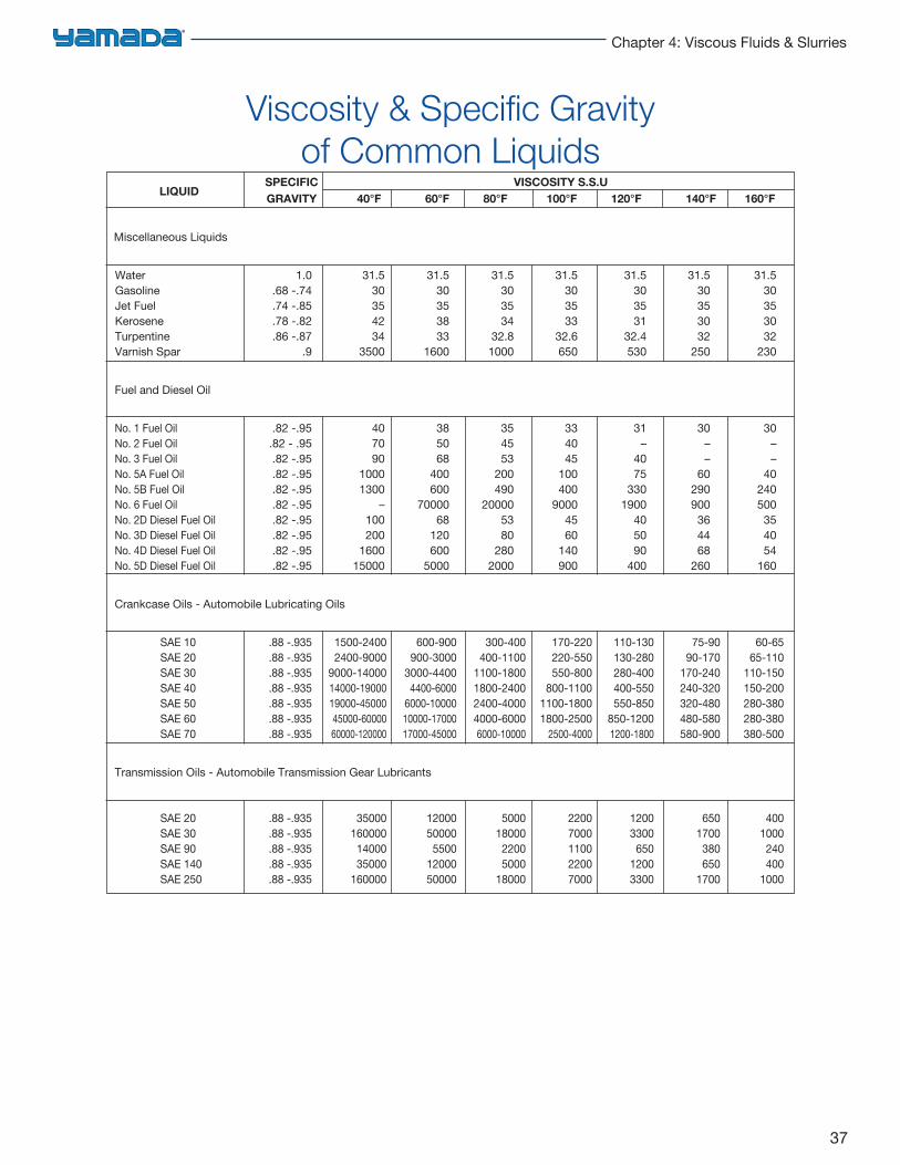
SPECIFIC VISCOSITY S.S.ULIQUID
GRAVITY 40°F 60°F 80°F 100°F 120°F 140°F 160°F
Miscellaneous Liquids
Water 1.0 31.5 31.5 31.5 31.5 31.5 31.5 31.5Gasoline .68 -.74 30 30 30 30 30 30 30Jet Fuel .74 -.85 35 35 35 35 35 35 35Kerosene .78 -.82 42 38 34 33 31 30 30Turpentine .86 -.87 34 33 32.8 32.6 32.4 32 32Varnish Spar .9 3500 1600 1000 650 530 250 230
Fuel and Diesel Oil
No. 1 Fuel Oil .82 -.95 40 38 35 33 31 30 30No. 2 Fuel Oil .82 - .95 70 50 45 40 – – –No. 3 Fuel Oil .82 -.95 90 68 53 45 40 – –No. 5A Fuel Oil .82 -.95 1000 400 200 100 75 60 40No. 5B Fuel Oil .82 -.95 1300 600 490 400 330 290 240No. 6 Fuel Oil .82 -.95 – 70000 20000 9000 1900 900 500No. 2D Diesel Fuel Oil .82 -.95 100 68 53 45 40 36 35No. 3D Diesel Fuel Oil .82 -.95 200 120 80 60 50 44 40No. 4D Diesel Fuel Oil .82 -.95 1600 600 280 140 90 68 54No. 5D Diesel Fuel Oil .82 -.95 15000 5000 2000 900 400 260 160
Crankcase Oils - Automobile Lubricating Oils
SAE 10 .88 -.935 1500-2400 600-900 300-400 170-220 110-130 75-90 60-65SAE 20 .88 -.935 2400-9000 900-3000 400-1100 220-550 130-280 90-170 65-110SAE 30 .88 -.935 9000-14000 3000-4400 1100-1800 550-800 280-400 170-240 110-150SAE 40 .88 -.935 14000-19000 4400-6000 1800-2400 800-1100 400-550 240-320 150-200SAE 50 .88 -.935 19000-45000 6000-10000 2400-4000 1100-1800 550-850 320-480 280-380 SAE 60 .88 -.935 45000-60000 10000-17000 4000-6000 1800-2500 850-1200 480-580 280-380SAE 70 .88 -.935 60000-120000 17000-45000 6000-10000 2500-4000 1200-1800 580-900 380-500
Transmission Oils - Automobile Transmission Gear Lubricants
SAE 20 .88 -.935 35000 12000 5000 2200 1200 650 400SAE 30 .88 -.935 160000 50000 18000 7000 3300 1700 1000SAE 90 .88 -.935 14000 5500 2200 1100 650 380 240SAE 140 .88 -.935 35000 12000 5000 2200 1200 650 400SAE 250 .88 -.935 160000 50000 18000 7000 3300 1700 1000
Viscosity & Specific Gravity of Common Liquids
38
Engineering Handbook for Diaphragm Pumps
SPECIFIC VISCOSITY S.S.U.LIQUID GRAVITY 70°F 100°F 130°F
Sugar, Syrups, Molasses, etc.
Corn Syrups 1.4 - 1.47 – 5,000-500,000 1,500-60,000Glucose 1.35-1.44 – 35,000 - 100,000 10,000-13,000Honey (Raw) 1.20 – 340 –Molasses 1.40-1.49 – 1,300 - 250,000 700-75,000Sugar Syrups 60 Brix 1.29 230 92 –Sugar Syrups 62 Brix 1.30 310 111 –Sugar Syrups 64 Brix 1.31 440 148 –Sugar Syrups 66 Brix 1.33 650 195 –Sugar Syrups 68 Brix 1.34 1000 275 –Sugar Syrups 70 Brix 1.35 1650 400 –Sugar Syrups 72 Brix 1.36 2700 640 –Sugar Syrups 74 Brix 1.38 5500 1100 –Sugar Syrups 76 Brix 1.39 10000 2000 –Corn Starch 22 Baume 1.18 150 130 –Corn Starch 24 Baume 1.20 600 440 –Corn Starch 25 Baume 1.21 1400 800 –Ink - Printers 1.0 - 1.38 – 2,500 - 10,000 1,100 - 3,000Ink - Newspaper – – 5,500 - 8,000 2400Tallow . 918 56 SSU at 212F
Tars
Coke Oven - Tar 1.12 + 3,000 - 8,000 650 -1,400 –Gas House - Tar 1.16 - 1.3 15,000-300,000 2,000-20,000 –
Crude Oils
Texas, Oklahoma . 81 -.916 100-700 34-210 –Wyoming, Montana . 86-.88 100-1100 46-320 –California . 78-.92 100-4500 34-700 –Pennsylvania . 8 -.85 100-200 38-86 –
Glycol
Propylene 1.038 240.6 – –Triethylene 1.125 185.7 – –Diethylene 1.12 149.7 – –Ethylene 1.125 88.4 – –Glycerine (100%) 1.26 2900 813 –Phenol (Carbolic Acid) . 95 -1.00 60 – –Silciate of Soda – – 356-640 –Sulfuric Acid (100%) 1.83 75 – –
Viscosity & Specific Gravity of Common Liquids
39
Chapter 4: Viscous Fluids & Slurries
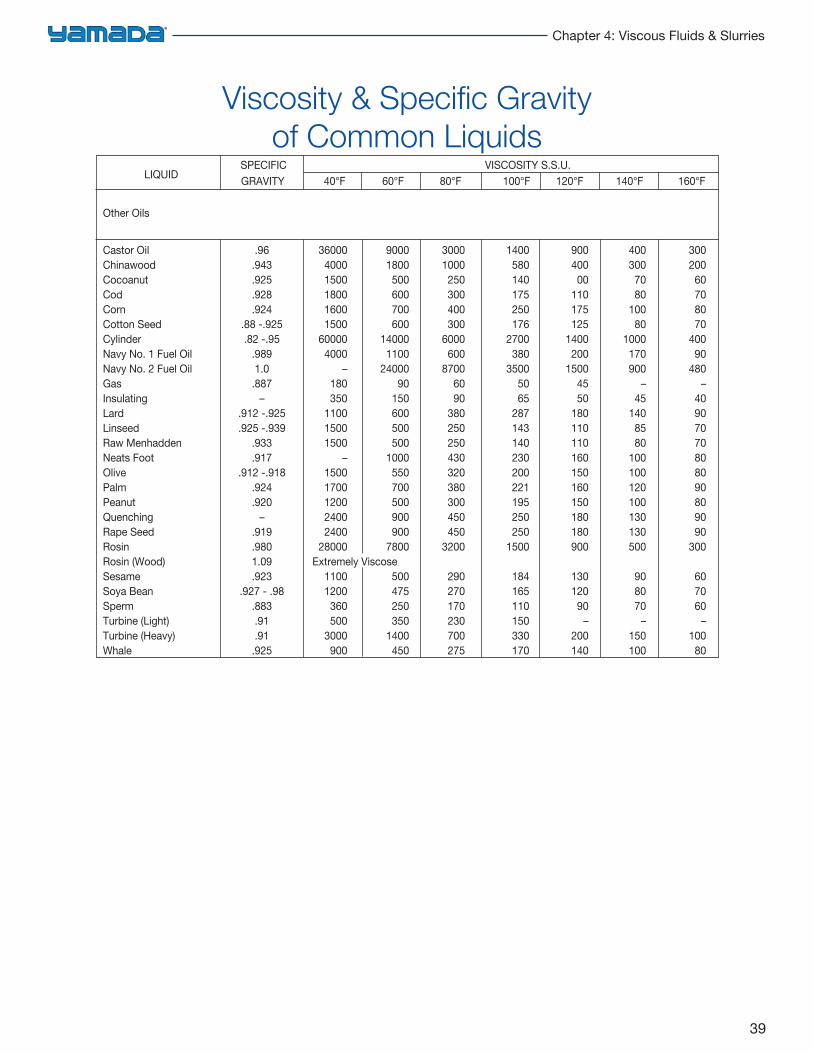
SPECIFIC VISCOSITY S.S.U.LIQUID GRAVITY 40°F 60°F 80°F 100°F 120°F 140°F 160°F
Other Oils
Castor Oil .96 36000 9000 3000 1400 900 400 300Chinawood .943 4000 1800 1000 580 400 300 200Cocoanut .925 1500 500 250 140 00 70 60Cod .928 1800 600 300 175 110 80 70Corn .924 1600 700 400 250 175 100 80Cotton Seed .88 -.925 1500 600 300 176 125 80 70Cylinder .82 -.95 60000 14000 6000 2700 1400 1000 400Navy No. 1 Fuel Oil .989 4000 1100 600 380 200 170 90Navy No. 2 Fuel Oil 1.0 – 24000 8700 3500 1500 900 480Gas .887 180 90 60 50 45 – –Insulating – 350 150 90 65 50 45 40Lard .912 -.925 1100 600 380 287 180 140 90Linseed .925 -.939 1500 500 250 143 110 85 70Raw Menhadden .933 1500 500 250 140 110 80 70Neats Foot .917 – 1000 430 230 160 100 80Olive .912 -.918 1500 550 320 200 150 100 80Palm .924 1700 700 380 221 160 120 90Peanut .920 1200 500 300 195 150 100 80Quenching – 2400 900 450 250 180 130 90Rape Seed .919 2400 900 450 250 180 130 90Rosin .980 28000 7800 3200 1500 900 500 300Rosin (Wood) 1.09 Extremely ViscoseSesame .923 1100 500 290 184 130 90 60Soya Bean .927 - .98 1200 475 270 165 120 80 70Sperm .883 360 250 170 110 90 70 60Turbine (Light) .91 500 350 230 150 – – –Turbine (Heavy) .91 3000 1400 700 330 200 150 100Whale .925 900 450 275 170 140 100 80
Viscosity & Specific Gravity of Common Liquids
40
Engineering Handbook for Diaphragm Pumps
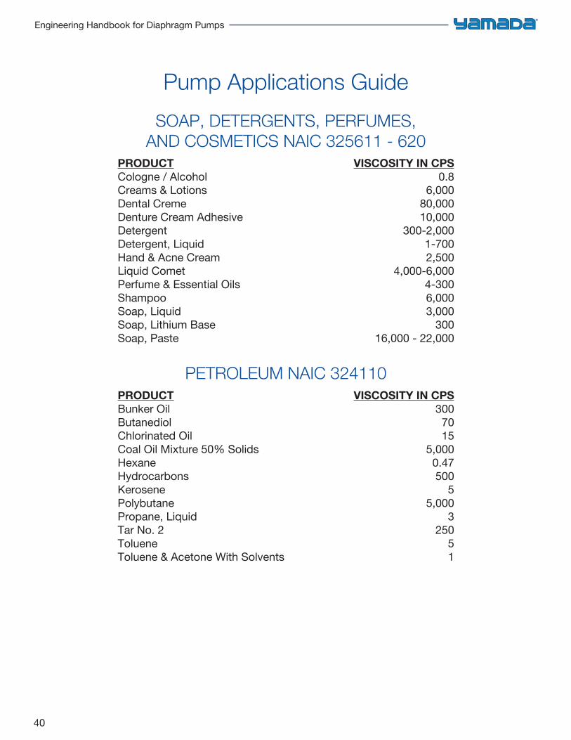
Pump Applications Guide
SOAP, DETERGENTS, PERFUMES, AND COSMETICS NAIC 325611 - 620
PRODUCT VISCOSITY IN CPSCologne / Alcohol 0.8Creams & Lotions 6,000Dental Creme 80,000Denture Cream Adhesive 10,000Detergent 300-2,000Detergent, Liquid 1-700Hand & Acne Cream 2,500Liquid Comet 4,000-6,000Perfume & Essential Oils 4-300Shampoo 6,000Soap, Liquid 3,000Soap, Lithium Base 300Soap, Paste 16,000 - 22,000
PETROLEUM NAIC 324110PRODUCT VISCOSITY IN CPSBunker Oil 300Butanediol 70Chlorinated Oil 15Coal Oil Mixture 50% Solids 5,000Hexane 0.47Hydrocarbons 500Kerosene 5Polybutane 5,000Propane, Liquid 3Tar No. 2 250Toluene 5Toluene & Acetone With Solvents 1
41
Chapter 4: Viscous Fluids & Slurries
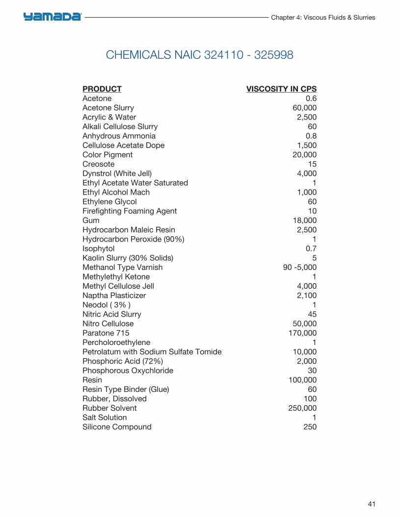
CHEMICALS NAIC 324110 - 325998
PRODUCT VISCOSITY IN CPSAcetone 0.6Acetone Slurry 60,000Acrylic & Water 2,500Alkali Cellulose Slurry 60Anhydrous Ammonia 0.8Cellulose Acetate Dope 1,500Color Pigment 20,000Creosote 15Dynstrol (White Jell) 4,000Ethyl Acetate Water Saturated 1Ethyl Alcohol Mach 1,000Ethylene Glycol 60Firefighting Foaming Agent 10Gum 18,000Hydrocarbon Maleic Resin 2,500Hydrocarbon Peroxide (90%) 1Isophytol 0.7Kaolin Slurry (30% Solids) 5Methanol Type Varnish 90 -5,000Methylethyl Ketone 1Methyl Cellulose Jell 4,000Naptha Plasticizer 2,100Neodol ( 3% ) 1Nitric Acid Slurry 45Nitro Cellulose 50,000Paratone 715 170,000Percholoroethylene 1Petrolatum with Sodium Sulfate Tomide 10,000Phosphoric Acid (72%) 2,000Phosphorous Oxychloride 30Resin 100,000Resin Type Binder (Glue) 60Rubber, Dissolved 100Rubber Solvent 250,000Salt Solution 1Silicone Compound 250
42
Engineering Handbook for Diaphragm Pumps
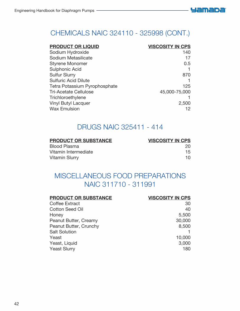
CHEMICALS NAIC 324110 - 325998 (CONT.)
PRODUCT OR LIQUID VISCOSITY IN CPSSodium Hydroxide 140Sodium Metasilicate 17Styrene Monomer 0.5Sulphonic Acid 1Sulfur Slurry 870Sulfuric Acid Dilute 1Tetra Potassium Pyrophosphate 125Tri-Acetate Cellulose 45,000-75,000Trichloroethylene 1Vinyl Butyl Lacquer 2,500Wax Emulsion 12
DRUGS NAIC 325411 - 414
PRODUCT OR SUBSTANCE VISCOSITY IN CPSBlood Plasma 20Vitamin Intermediate 15Vitamin Slurry 10
MISCELLANEOUS FOOD PREPARATIONS NAIC 311710 - 311991
PRODUCT OR SUBSTANCE VISCOSITY IN CPSCoffee Extract 30Cotton Seed Oil 40Honey 5,500Peanut Butter, Creamy 30,000Peanut Butter, Crunchy 8,500Salt Solution 1Yeast 10,000Yeast, Liquid 3,000Yeast Slurry 180
43
Chapter 4: Viscous Fluids & Slurries
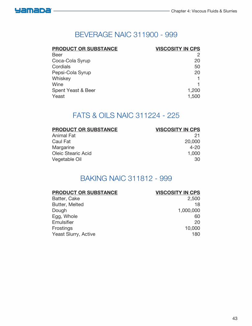
BEVERAGE NAIC 311900 - 999
PRODUCT OR SUBSTANCE VISCOSITY IN CPSBeer 2Coca-Cola Syrup 20Cordials 50Pepsi-Cola Syrup 20Whiskey 1Wine 1Spent Yeast & Beer 1,200Yeast 1,500
FATS & OILS NAIC 311224 - 225
PRODUCT OR SUBSTANCE VISCOSITY IN CPSAnimal Fat 21Caul Fat 20,000Margarine 4-20Oleic Stearic Acid 1,000Vegetable Oil 30
BAKING NAIC 311812 - 999
PRODUCT OR SUBSTANCE VISCOSITY IN CPSBatter, Cake 2,500Butter, Melted 18Dough 1,000,000Egg, Whole 60Emulsifier 20Frostings 10,000Yeast Slurry, Active 180
44
Engineering Handbook for Diaphragm Pumps
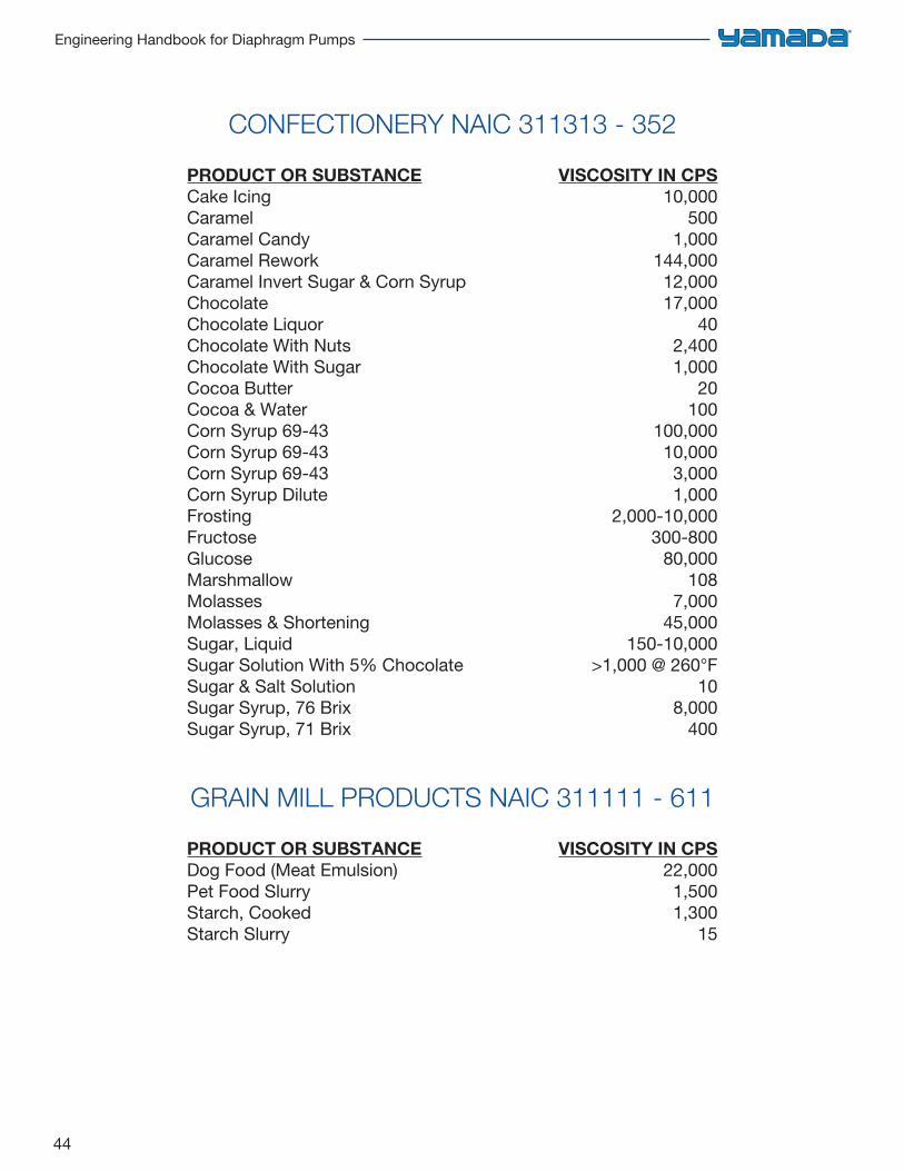
CONFECTIONERY NAIC 311313 - 352
PRODUCT OR SUBSTANCE VISCOSITY IN CPSCake Icing 10,000Caramel 500Caramel Candy 1,000Caramel Rework 144,000Caramel Invert Sugar & Corn Syrup 12,000Chocolate 17,000Chocolate Liquor 40Chocolate With Nuts 2,400Chocolate With Sugar 1,000Cocoa Butter 20Cocoa & Water 100Corn Syrup 69-43 100,000Corn Syrup 69-43 10,000Corn Syrup 69-43 3,000Corn Syrup Dilute 1,000Frosting 2,000-10,000Fructose 300-800Glucose 80,000Marshmallow 108Molasses 7,000Molasses & Shortening 45,000Sugar, Liquid 150-10,000Sugar Solution With 5% Chocolate >1,000 @ 260°FSugar & Salt Solution 10Sugar Syrup, 76 Brix 8,000Sugar Syrup, 71 Brix 400
GRAIN MILL PRODUCTS NAIC 311111 - 611
PRODUCT OR SUBSTANCE VISCOSITY IN CPSDog Food (Meat Emulsion) 22,000Pet Food Slurry 1,500Starch, Cooked 1,300Starch Slurry 15
45
Chapter 4: Viscous Fluids & Slurries
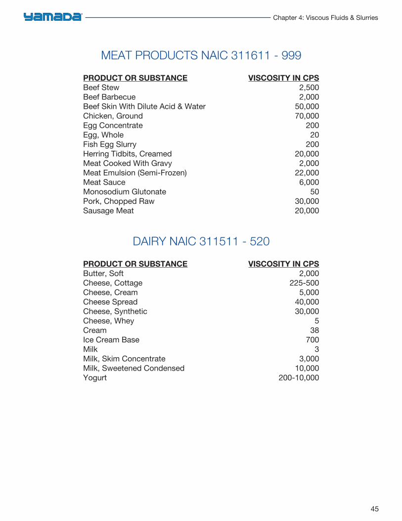
MEAT PRODUCTS NAIC 311611 - 999
PRODUCT OR SUBSTANCE VISCOSITY IN CPSBeef Stew 2,500Beef Barbecue 2,000Beef Skin With Dilute Acid & Water 50,000Chicken, Ground 70,000Egg Concentrate 200Egg, Whole 20Fish Egg Slurry 200Herring Tidbits, Creamed 20,000Meat Cooked With Gravy 2,000Meat Emulsion (Semi-Frozen) 22,000Meat Sauce 6,000Monosodium Glutonate 50Pork, Chopped Raw 30,000Sausage Meat 20,000
DAIRY NAIC 311511 - 520
PRODUCT OR SUBSTANCE VISCOSITY IN CPSButter, Soft 2,000Cheese, Cottage 225-500Cheese, Cream 5,000Cheese Spread 40,000Cheese, Synthetic 30,000Cheese, Whey 5Cream 38Ice Cream Base 700Milk 3Milk, Skim Concentrate 3,000Milk, Sweetened Condensed 10,000Yogurt 200-10,000
46
Engineering Handbook for Diaphragm Pumps
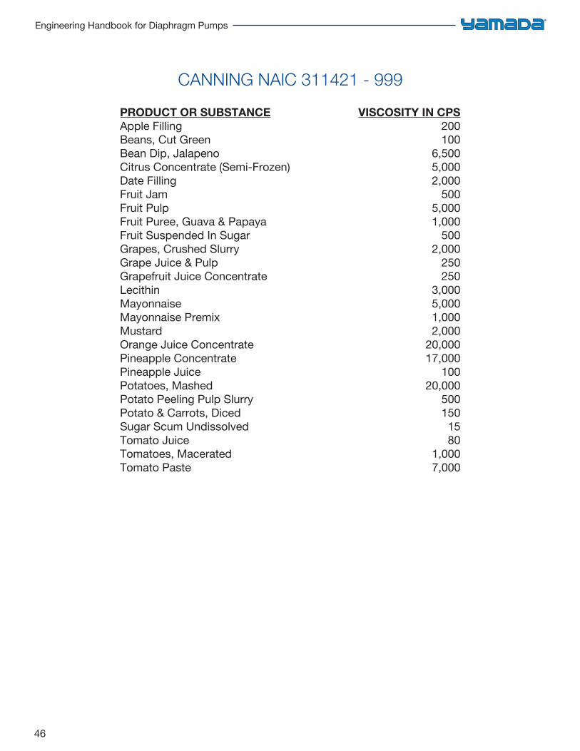
CANNING NAIC 311421 - 999
PRODUCT OR SUBSTANCE VISCOSITY IN CPSApple Filling 200Beans, Cut Green 100Bean Dip, Jalapeno 6,500Citrus Concentrate (Semi-Frozen) 5,000Date Filling 2,000Fruit Jam 500Fruit Pulp 5,000Fruit Puree, Guava & Papaya 1,000Fruit Suspended In Sugar 500Grapes, Crushed Slurry 2,000Grape Juice & Pulp 250Grapefruit Juice Concentrate 250Lecithin 3,000Mayonnaise 5,000Mayonnaise Premix 1,000Mustard 2,000Orange Juice Concentrate 20,000Pineapple Concentrate 17,000Pineapple Juice 100Potatoes, Mashed 20,000Potato Peeling Pulp Slurry 500Potato & Carrots, Diced 150Sugar Scum Undissolved 15Tomato Juice 80Tomatoes, Macerated 1,000Tomato Paste 7,000
47
Chapter 4: Viscous Fluids & Slurries
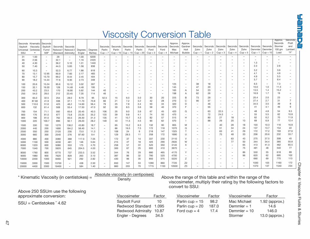
Viscosity Conversion TableSecondsSaybolt
UniversalSSU31354050
60708090
100150200250
300400500600
7008009001000
1500200025003000
4000500060007000
8000900010000
1500020000
KinematicViscosityCentistokes
*1.002.564.307.40
10.313.115.718.2
20.632.143.254.0
65.087.60110.0132
154176198220
330440550660
880110013201540
176019802200
33004400
SecondsSayboltFurrolSSF
––––
–12.9513.7014.44
15.2419.3023.528.0
32.541.951.661.4
71.181.091.0100.7
150200250300
400500600700
8009001000
15002000
SecondsRedwood 1(Standard)
2932.136.244.3
52.360.969.277.6
85.6128170212
254338423508
592677762896
1270169021202540
3380423050805920
677076208460
1370018400
SecondsRedwood 2(Admirelty)
––
5.105.83
6.777.608.449.30
10.1214.4818.9023.45
28.037.146.255.4
65.673.883.092.1
138.2184.2230276
368461553645
737829921
––
DegreesEngler1.001.161.311.58
1.882.172.452.73
3.024.485.927.35
8.7911.7014.6017.50
20.4523.3526.3029.20
43.8058.4073.087.60
117.0146175
204.5
233.5263292
438584
Degrees Barbay620024201440838
618483404348
307195144114
9570.856.447.0
40.335.231.328.2
18.714.111.39.4
7.055.644.704.03
3.523.132.82
2.501.40
SecondsParlin
Cup = 7––––
––––
––
4046
52.5667992
106120135149
––––
––––
–––
––
SecondsParlin
Cup = 10––––
––––
––––
15212530
35394143
6586108129
172215258300
344387430
650860
SecondsParlin
Cup = 15––––
––––
––––
6.07.27.88.5
9.09.810.711.5
15.219.524
28.5
37475767
768696
147203
SecondsParlin
Cup = 20––––
––––
––––
3.03.23.43.6
3.94.14.34.5
6.37.5911
14182225
293235
5370
SecondsFord
Cup = 3––––
––––
––––
30425058
67748290
132172218258
337425520600
680780850
12801715
SecondsFord
Cup = 4––––
––––
––––
20283440
45505762
90118147172
230290350410
465520575
8601150
Approx.Seconds
MacMichael
––––
––––
125145165198
225270320370
420470515570
805107013251690
2110263531453670
417047005220
772010500
Approx.Gardner
HoltBubble
––––
––––
––AA
BCDF
G–HI
MQTU
VWX–
Y–Z
Z2Z3
SecondsZohn
Cup = 1––––
––––
38475462
7390––
––––
––––
––––
–––
––
SecondsZohn
Cup = 2––––
––––
18202326
29374655
63728088
––––
––––
–––
––
SecondsZohn
Cup = 3––––
––––
––––
––––
22.524.52729
40516375
––––
–––
––
SecondsZohn
Cup = 4––––
––––
––––
––––
––
1820
28344148
6377––
–––
––
SecondsZohn
Cup = 5––––
––––
––––
––––
–––
13
18242933
43506575
8696–
––
SecondsDemmlerCup = 1
––
1.32.3
3.24.14.95.7
6.510.013.516.9
20.427.434.541
48556269
103137172206
275344413481
550620690
10301370
SecondsDemmlerCup = 10
––––
––––
–1.01.41.7
2.02.73.54.1
4.85.56.26.9
10.313.717.220.6
27.534.441.348
556269
103137
Approx.SecondsStormer100 gmLoad
–––
2.6
3.64.65.56.4
7.311.315.219
23313946
54627077
116154193232
308385462540
618695770
11601540
SecondsPrattand
Lambert“F”––––
––––
––––
–789
9.510.811.912.4
16.822
27.633.7
4555.865.577
89102113
172234
* Kinematic Viscosity (in centistokes) = Above the range of this table and within the range of theviscosimeter, multiply their rating by the following factors toconvert to SSU:
Above 250 SSUm use the followingapproximate conversion:SSU = Centistokes ˘ 4.62
Absolute viscosity (in centipoises)Density
Viscosimeter Factor Viscosimeter Factor Viscosimeter FactorSaybolt Furol 10 Parlin cup = 15 98.2 Mac Michael 1.92 (approx.)Redwood Standard 1.095 Parlin cup = 20 187.0 Demmler = 1 14.6Redwood Admiralty 10.87 Ford cup = 4 17.4 Demmler = 10 146.0Engler - Degrees 34.5 Stormer 13.0 (approx.)
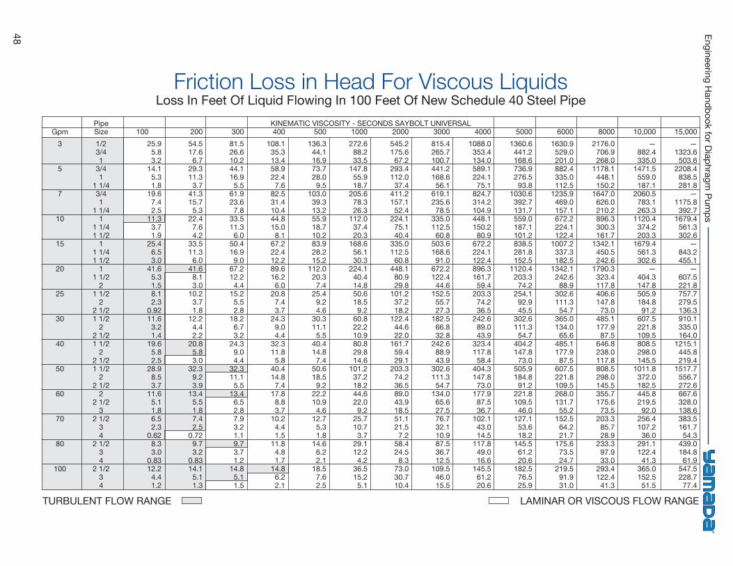
48 Engineering Handbook for Diaphragm
Pumps
Friction Loss in Head For Viscous LiquidsLoss In Feet Of Liquid Flowing In 100 Feet Of New Schedule 40 Steel Pipe
Gpm3
5
7
10
15
20
25
30
40
50
60
70
80
100
PipeSize1/23/41
3/41
1 1/43/41
1 1/41
1 1/41 1/2
11 1/41 1/2
11 1/2
21 1/2
22 1/21 1/2
22 1/21 1/2
22 1/21 1/2
22 1/2
22 1/2
32 1/2
34
2 1/234
2 1/234
10025.95.83.2
14.15.31.8
19.67.42.5
11.33.71.9
25.46.53.0
41.65.31.58.12.3
0.9211.63.21.4
19.65.82.5
28.98.53.7
11.65.11.86.52.3
0.628.33.0
0.8312.24.41.2
20054.517.66.7
29.311.33.7
41.315.75.3
22.47.64.2
33.511.36.0
41.68.13.0
10.23.71.8
12.24.42.2
20.85.83.0
32.39.23.9
13.45.51.87.42.5
0.729.73.2
0.8314.15.11.3
30081.526.610.244.116.95.5
61.923.67.8
33.511.36.0
50.416.99.0
67.212.24.4
15.25.52.8
18.26.73.2
24.39.04.4
32.311.15.5
13.46.52.87.93.21.19.73.71.2
14.85.11.5
400108.135.313.458.922.47.6
82.531.410.444.815.08.1
67.222.412.289.616.26.0
20.87.43.7
24.39.04.4
32.311.85.8
40.414.87.4
17.88.83.7
10.24.41.5
11.84.81.7
14.86.22.1
500136.344.116.973.728.09.5
103.039.313.255.918.710.283.928.215.2
112.020.37.4
25.49.24.6
30.311.15.5
40.414.87.4
50.618.59.2
22.210.94.6
12.75.31.8
14.66.22.1
18.57.62.5
1000272.688.233.5
147.855.918.7
205.678.326.3
112.037.420.3
168.656.130.3
224.140.414.850.618.59.2
60.822.210.980.829.814.6
101.237.218.244.622.09.2
25.710.73.7
29.112.24.2
36.515.25.1
2000545.2175.667.2
293.4112.037.4
411.2157.152.4
224.175.140.4
335.0112.560.8
448.180.929.8
101.237.218.2
122.444.622.0
161.759.429.1
203.374.236.589.043.918.551.121.57.2
58.424.58.3
73.030.710.4
3000815.4265.7100.7441.2168.656.1
619.1235.678.5
335.0112.560.8
503.6168.691.0
672.2122.444.6
152.555.727.3
182.566.832.8
242.688.943.9
302.6111.354.7
134.065.627.576.732.110.987.536.712.5
109.546.015.5
40001088.0353.4134.0589.1224.175.1
824.7314.2104.9448.1150.280.9
672.2224.1122.4896.3161.759.4
203.374.236.5
242.689.043.9
323.4117.858.4
404.3147.873.0
177.987.536.7
102.143.014.5
117.849.016.6
145.561.220.6
50001360.6441.2168.6736.9276.593.8
1030.6392.7131.7559.0187.1101.2838.5281.8152.5
1120.4203.374.2
254.192.945.5
302.6111.354.7
404.2147.873.0
505.9184.891.2
221.8109.546.0
127.153.618.2
145.561.220.6
182.576.525.9
60001630.9529.0201.0882.4335.0112.5
1235.9469.0157.1672.2224.1122.4
1007.2337.3182.5
1342.1242.688.9
302.6111.354.7
365.0134.065.6
485.1177.987.5
607.5221.8109.5268.0131.755.2
152.564.221.7
175.673.524.7
219.591.931.0
80002176.0706.9268.0
1178.1448.1150.2
1647.0626.0210.2896.3300.3161.7
1342.1450.5242.6
1790.3323.4117.8406.6147.873.0
485.1177.987.5
646.8238.0117.8808.5298.0145.5355.7175.673.5
203.385.728.9
233.397.933.0
293.4122.441.3
10,000—
882.4335.0
1471.5559.0187.1
2060.5783.1263.3
1120.4374.2203.3
1679.4561.3302.6
—404.3147.8505.9184.891.2
607.5221.8109.5808.5298.0145.5
1011.8372.0182.5445.8219.592.0
256.4107.236.0
291.1122.441.3
365.0152.551.5
15,000—
1323.6503.6
2208.4838.5281.8
—1175.8392.7
1679.4561.3302.6
—843.2455.1
—607.5221.8757.7279.5136.3910.1335.0164.0
1215.1445.8219.4
1517.7556.7272.6667.6328.0138.6383.5161.754.3
439.0184.861.9
547.5228.777.4
KINEMATIC VISCOSITY - SECONDS SAYBOLT UNIVERSAL
TURBULENT FLOW RANGE LAMINAR OR VISCOUS FLOW RANGE
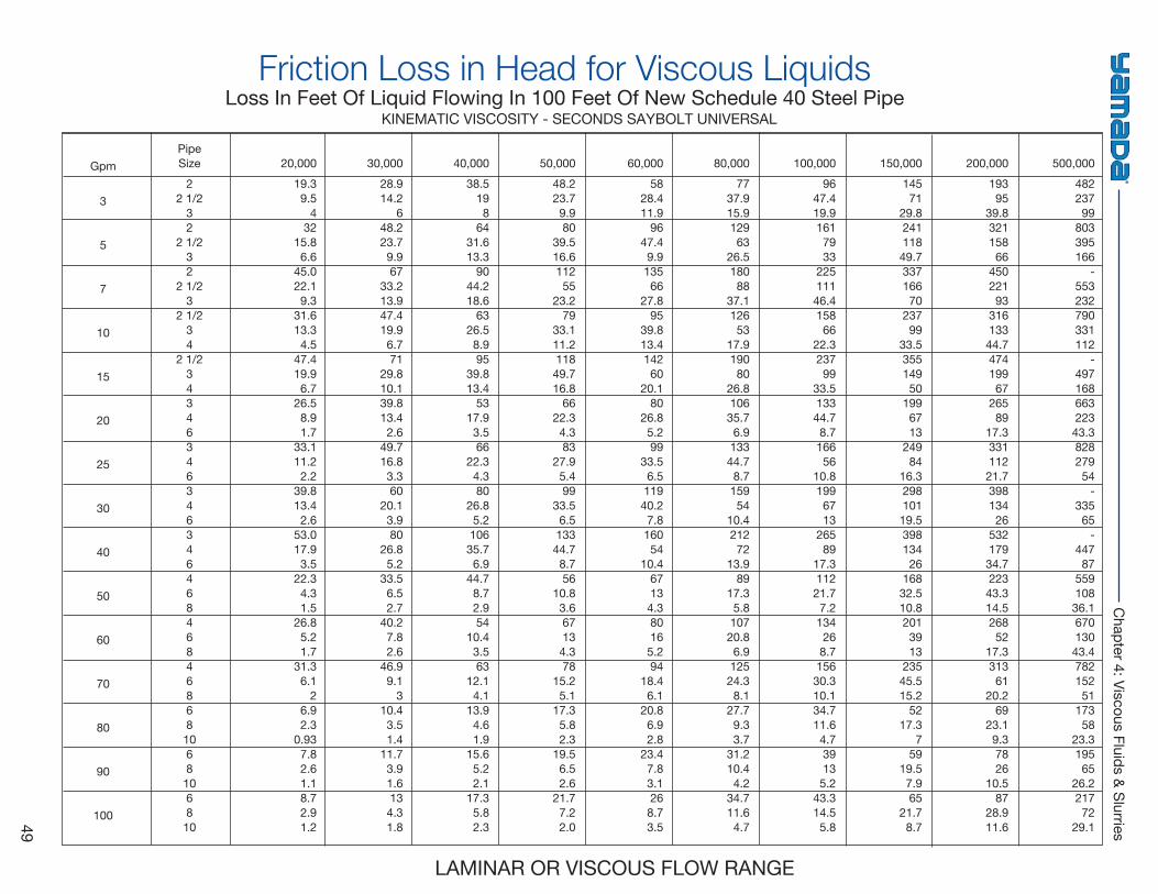
49
Chapter 4: Viscous Fluids & Slurries
Friction Loss in Head for Viscous LiquidsLoss In Feet Of Liquid Flowing In 100 Feet Of New Schedule 40 Steel Pipe
Gpm
3
5
7
10
15
20
25
30
40
50
60
70
80
90
100
PipeSize
22 1/2
32
2 1/232
2 1/23
2 1/234
2 1/234346346346346468468468681068106810
20,00019.39.5
432
15.86.6
45.022.19.3
31.613.34.5
47.419.96.7
26.58.91.7
33.111.22.2
39.813.42.6
53.017.93.5
22.34.31.5
26.85.21.7
31.36.1
26.92.3
0.937.82.61.18.72.91.2
30,00028.914.2
648.223.79.967
33.213.947.419.96.771
29.810.139.813.42.6
49.716.83.360
20.13.980
26.85.2
33.56.52.7
40.27.82.6
46.99.1
310.43.51.4
11.73.91.6134.31.8
40,00038.5
198
6431.613.3
9044.218.6
6326.58.995
39.813.4
5317.93.566
22.34.380
26.85.210635.76.9
44.78.72.954
10.43.563
12.14.1
13.94.61.9
15.65.22.1
17.35.82.3
50,00048.223.79.980
39.516.611255
23.279
33.111.211849.716.8
6622.34.383
27.95.499
33.56.513344.78.756
10.83.667134.378
15.25.1
17.35.82.3
19.56.52.6
21.77.22.0
60,00058
28.411.9
9647.49.913566
27.895
39.813.414260
20.180
26.85.299
33.56.511940.27.816054
10.467134.380165.294
18.46.1
20.86.92.8
23.47.83.1268.73.5
80,00077
37.915.912963
26.518088
37.112653
17.919080
26.810635.76.913344.78.715954
10.421272
13.989
17.35.810720.86.912524.38.1
27.79.33.7
31.210.44.2
34.711.64.7
100,00096
47.419.91617933
22511146.415866
22.323799
33.513344.78.716656
10.81996713
26589
17.311221.77.2134268.715630.310.134.711.64.739135.2
43.314.55.8
150,00014571
29.824111849.733716670
23799
33.535514950
1996713
24984
16.329810119.539813426
16832.510.82013913
23545.515.2
5217.3
759
19.57.965
21.78.7
200,00019395
39.832115866
45022193
31613344.747419967
26589
17.333111221.739813426
53217934.722343.314.526852
17.331361
20.269
23.19.37826
10.587
28.911.6
500,00048223799
803395166
-553232790331112
-49716866322343.382827954
-33565
-44787
55910836.167013043.478215251
17358
23.319565
26.221772
29.1
LAMINAR OR VISCOUS FLOW RANGE
KINEMATIC VISCOSITY - SECONDS SAYBOLT UNIVERSAL
50
Engineering Handbook for Diaphragm Pumps
Pumping SlurrySOLIDS HANDLING CAPABILITIES, SUCTION PRESSURE LIMITATIONS
Pumping Slurry
Normally when a metal casing and a rubber diaphragm are utilized, slurry of about 30 - 40% can be pumped, though care must be taken to the size of slurry particles. When pumping slurry of a high sedimentation rate, pay attention to the following points:1. Secure a minimum flow velocity of 1.1 Ft/Sec(20 m/min)Please note that 1.1 Ft/Sec is a minimum velocity. A velocity of 3 Ft/Sec (55 m/min) to 7 Ft/Sec (130 m/min) may be required to keep solids in suspension, although it is ideal to keep velocities as slow as possible to minimize abrasion.2. Always consider inlet pressure. Inversion of thediaphragm can occur if over 20 PSI (1.4 Bars) inlet pressure on rubber diaphragms and 4.3 PSI (0.3 Bars) for PTFE diaphragms.3. When the pump is at a standstill, attemptcleaning. Don’t let the slurry set up in the pump.
4. If utilizing plastic pump casing, take extraprecaution when pumping highly abrasive slurry. The content shall be kept below 10Wt%.
Weight concentration (Wt%) = SW + S
(X) 100
Where, W = water (kg) S = Solid matter (kg)
5. If slurry particles are uneven, install a strainer on the suction side of the pump so large foreign matter will not enter.
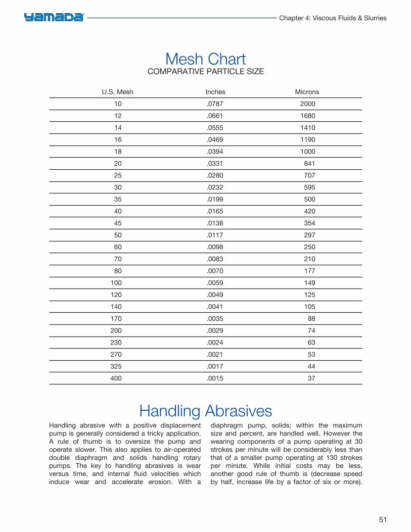
51
Chapter 4: Viscous Fluids & Slurries
Handling abrasive with a positive displacement pump is generally considered a tricky application. A rule of thumb is to oversize the pump and operate slower. This also applies to air-operated double diaphragm and solids handling rotary pumps. The key to handling abrasives is wear versus time, and internal fluid velocities which induce wear and accelerate erosion. With a
diaphragm pump, solids; within the maximum size and percent, are handled well. However the wearing components of a pump operating at 30 strokes per minute will be considerably less than that of a smaller pump operating at 130 strokes per minute. While initial costs may be less, another good rule of thumb is (decrease speed by half, increase life by a factor of six or more).
Mesh ChartCOMPARATIVE PARTICLE SIZE
U.S. Mesh Inches Microns10 .0787 200012 .0661 168014 .0555 141016 .0469 119018 .0394 100020 .0331 84125 .0280 70730 .0232 59535 .0199 50040 .0165 42045 .0138 35450 .0117 29760 .0098 25070 .0083 21080 .0070 177
100 .0059 149120 .0049 125140 .0041 105170 .0035 88200 .0029 74230 .0024 63270 .0021 53325 .0017 44400 .0015 37
Handling Abrasives
52
Engineering Handbook for Diaphragm Pumps
The typical pump performance curve is based on water which has a specific gravity of 1.0. Pumping a liquid with a specific gravity other than 1.0 will affect the pump’s performance. Fluids with a specific gravity higher than 1.0SG will require more energy to pump the same volume of liquid as water. Likewise, if the fluid has a lower specific gravity than 1.0SG, it will require less energy to move the same volume of liquid than water.As is the case with power pumps, often the discharge conditions are given in pounds per square inch gauge (PSIG).To convert this to feet of head, multiply PSIG by 2.31.To illustrate specific gravity correction, we will use the pump curve on page 2 which shows a design
point of 60 GPM @ 75’ TDH with a specific gravity of 1.0.Using a specific gravity of 1.85, the corrected total dynamic head would be 40.5’ TDH.However, you would still need to read the air requirements for the 75’ TDH mark which is 60 PSIG @ 35 SCFM.If on the other hand, if someone wants 60 GPM @ 75’ TDH and tells you that the specific gravity is 1.85, you would multiply the ‘TDH x S.G.75’ TDH x 1.85 S.G. = 138.75’138.75’ TDH would be the point on the curve you would read for your air requirements, which would be 95PSIG @ 48 SCFM.
Specific Gravity
53
Chapter 5: Materials of Construction
Typical Wetted Materials of Construction 54
Diaphragm Pressure Limits 55
Typical Diaphragm Materials 55
Pressure vs. Temperature 56
Estimated Diaphragm Life Calculation 57
Effective Diaphragm Area (AEFF) 58
Special Surface Finishes 59
RA Surface Finish 60
Materials of Construction
54
Engineering Handbook for Diaphragm Pumps
Typical Wetted Materials of Construction
POLYPROPYLENE (PP/PPG)
Temperature range: 30° to 180°FGood chemical resistanceLightweightLimited temperature / pressure capabilitiesNot compatible with petroleum based solventsCan be glass filled for added mechanical strength
KYNAR® (PVDF)
Temperature range: 0° to 212°FExcellent chemical resistanceGood strength / higher temperature capabilityCan be carbon filled for electrical conductivity (groundability)
ALUMINUM (356-T6)
Used in many non-corrosive, non-abrasive applicationsLightweight
CAST IRON (FC)
Used with a variety of non-corrosive servicesGood for slurry applications
STAINLESS STEEL (316SS)
Used with more chemically active fluidsHigh abrasion resistance
PTFE
Temperature range: 32° to 176°FInert to most chemicals100% Virgin PTFE
Plastic pumps in general are recommended for strong acids and caustics and not recommended for high temperatures or slurries.Metal pumps in general are good for abrasion resistance, solvents, hydrocarbons, and high temperature applications.We do not show the temperature limits on metal pumps because body material temperature limits will exceed elastomer temperature limits.
55
Chapter 5: Materials of Construction
Typical Diaphragm MaterialsRUBBER COMPOUNDS
BUNA N (NBR)
Temperature range: 10°F to 180°FExcellent for oil / petroleum based fluidsIdentification: Red or pink dot / Diaphragm is black
NEOPRENE™ (CR)
Temperature range: 0°F to 180°FExcellent elastomer for use in non-aggressive applicationsGood for abrasive materialsIdentification: No dot / Diaphragm is dull black
NORDEL® (EPDM)
Temperature range: -40°F to 210°FGood for extremely cold applicationsGood resistance to acids and causticsIdentification: Green or blue dot / Diaphragm is black
VITON® (FPM)
Temperature range: -20°F to 248°FExcellent for aggressive fluids such as aromatic or chlorinated hydrocarbons and acidsGood for high temperature applicationsIdentification: Silver dot / Diaphragm is black
NOTE: For estimated diaphragm cycle life, consult pump manufacturer.
Rubber diaphragms can handle a maximum positive inlet pressure of 20 PSIG dependent upon pump size, pump design and diaphragm material.PTFE diaphragms are limited to 4.3 PSIG (10’) positive inlet pressure due to their poor flexibility and low tolerances for mechanical stress.
Back up diaphragms may be used in connection with PTFE diaphragms to help extend teflon diaphragm life in severe applications.Typically rubber diaphragms can operate under any amount of vacuum, however teflon diaphragms are generally limited to 16” HG.
Diaphragm Pressure Limits
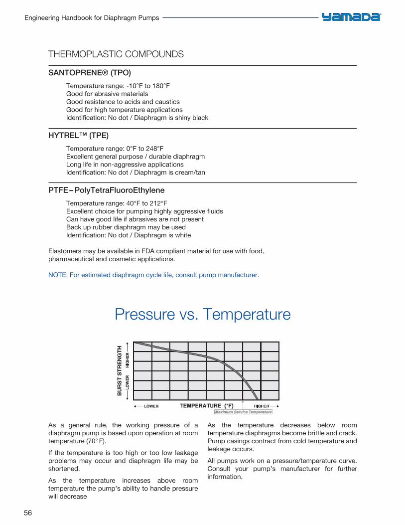
56
Engineering Handbook for Diaphragm Pumps
THERMOPLASTIC COMPOUNDS
SANTOPRENE® (TPO)
Temperature range: -10°F to 180°FGood for abrasive materialsGood resistance to acids and causticsGood for high temperature applicationsIdentification: No dot / Diaphragm is shiny black
HYTREL™ (TPE)
Temperature range: 0°F to 248°FExcellent general purpose / durable diaphragmLong life in non-aggressive applicationsIdentification: No dot / Diaphragm is cream/tan
PTFE – PolyTetraFluoroEthylene
Temperature range: 40°F to 212°FExcellent choice for pumping highly aggressive fluidsCan have good life if abrasives are not presentBack up rubber diaphragm may be usedIdentification: No dot / Diaphragm is white
Elastomers may be available in FDA compliant material for use with food, pharmaceutical and cosmetic applications.
NOTE: For estimated diaphragm cycle life, consult pump manufacturer.
As a general rule, the working pressure of a diaphragm pump is based upon operation at room temperature (70° F).If the temperature is too high or too low leakage problems may occur and diaphragm life may be shortened.As the temperature increases above room temperature the pump’s ability to handle pressure will decrease
As the temperature decreases below room temperature diaphragms become brittle and crack. Pump casings contract from cold temperature and leakage occurs.All pumps work on a pressure/temperature curve. Consult your pump’s manufacturer for further information.
Pressure vs. Temperature
57
Chapter 5: Materials of Construction
Estimated Diaphragm Life Calculation
Formula for Calculation:
1. GPMA ÷ GPMM = % Max Flow Rate2. % Max Flow Rate x MSPM = SPMA3. SPMA x T = SPD4. EDL ÷ SPD = AEL
NOTE:
GPMA = Gallons Per Minute Actual OutputGPMM = Gallons Per Minute Max. OutputMSPM = Maximum Strokes Per MinuteSPMA = Strokes Per Minute Actual
T = Time, in minutes, pump runs per daySPD = Strokes Per DayEDL = Estimated Diaphragm LifeAEL = Actual Estimated Life
EXAMPLE: NDP-20BST, @ 10GPM, 4 hrs. per day operation
1. 10 GPM ÷ 21 = .4762. .476 x 195 = 92.823. 92.82 x 240 = 22,2774. 8,000,000 ÷ 22,277 = 359 Estimated life in days
NOTE: There are many variables which will affect diaphragm life and thus this calculation is just an estimation and should be regarded as such.
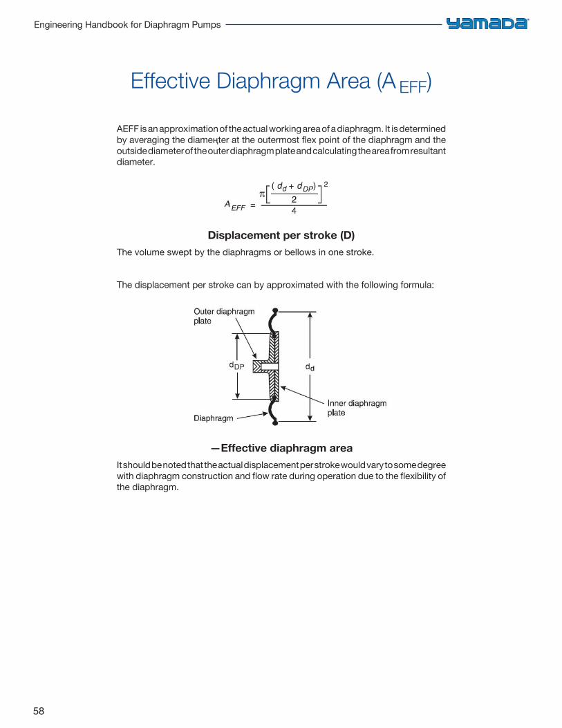
58
Engineering Handbook for Diaphragm Pumps
Effective Diaphragm Area (A EFF)
AEFF is an approximation of the actual working area of a diaphragm. It is determined by averaging the diameңter at the outermost flex point of the diaphragm and the outside diameter of the outer diaphragm plate and calculating the area from resultant diameter.
Displacement per stroke (D)The volume swept by the diaphragms or bellows in one stroke.
The displacement per stroke can by approximated with the following formula:
—Effective diaphragm areaIt should be noted that the actual displacement per stroke would vary to some degree with diaphragm construction and flow rate during operation due to the flexibility of the diaphragm.
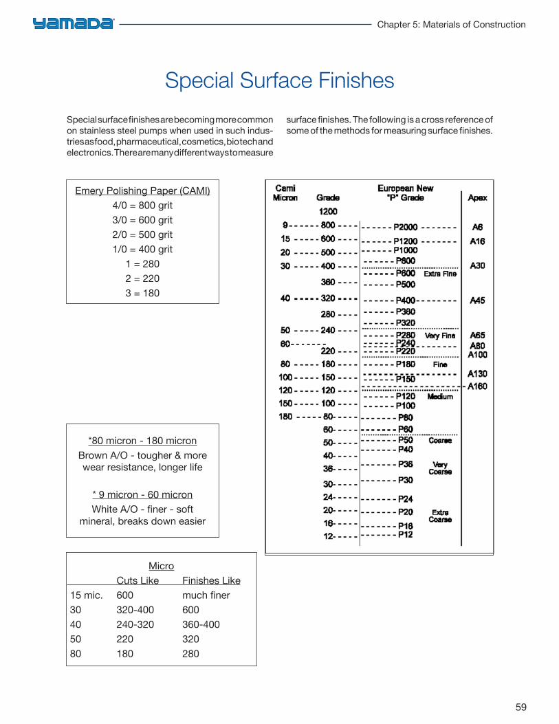
59
Chapter 5: Materials of Construction
Special surface finishes are becoming more common on stainless steel pumps when used in such indus-tries as food, pharmaceutical, cosmetics, bio tech and electronics. There are many different ways to measure
surface finishes. The following is a cross reference of some of the methods for measuring surface finishes.
Special Surface Finishes
Emery Polishing Paper (CAMI)4/0 = 800 grit3/0 = 600 grit2/0 = 500 grit1/0 = 400 grit
1 = 2802 = 2203 = 180
*80 micron - 180 micronBrown A/O - tougher & morewear resistance, longer life
* 9 micron - 60 micronWhite A/O - finer - soft
mineral, breaks down easier
Micro Cuts Like Finishes Like 15 mic. 600 much finer 30 320-400 600 40 240-320 360-400 50 220 320 80 180 280
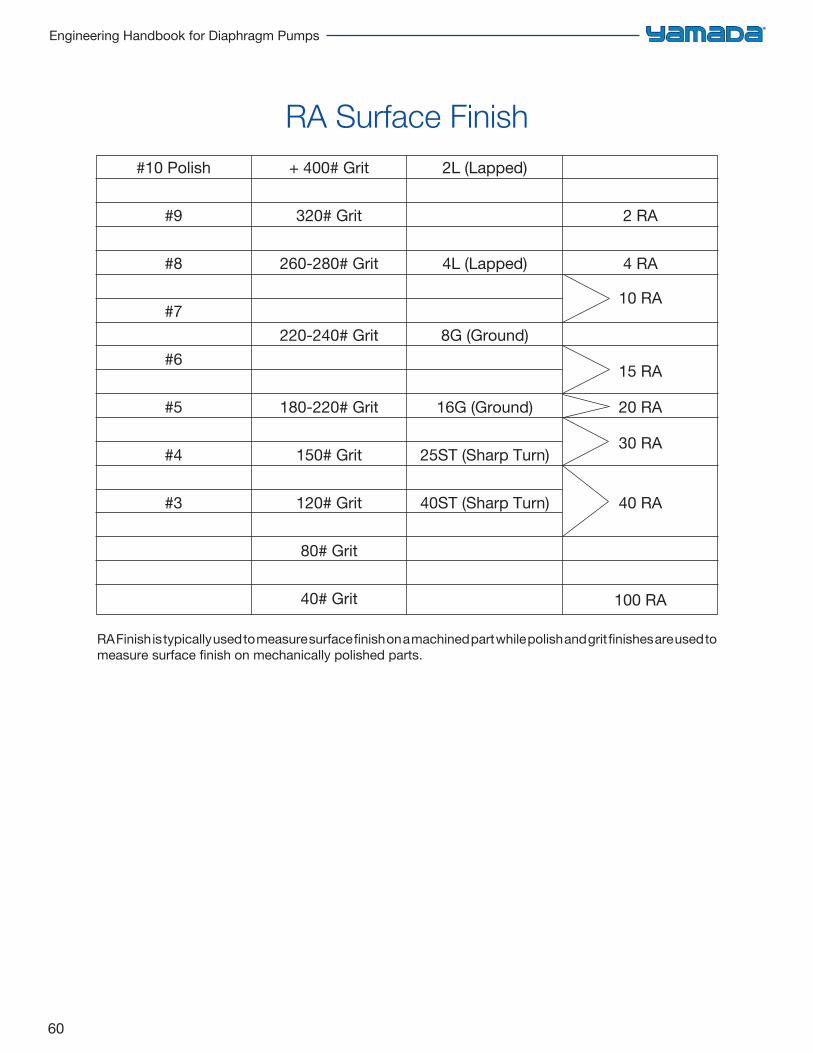
60
Engineering Handbook for Diaphragm Pumps
RA Surface Finish#10 Polish
#9
#8
#7
#6
#5
#4
#3
+ 400# Grit
320# Grit
260-280# Grit
220-240# Grit
180-220# Grit
150# Grit
120# Grit
80# Grit
40# Grit
2L (Lapped)
4L (Lapped)
8G (Ground)
16G (Ground)
25ST (Sharp Turn)
40ST (Sharp Turn)
2 RA
4 RA
10 RA
15 RA
20 RA
30 RA
40 RA
100 RA
RA Finish is typically used to measure surface finish on a machined part while polish and grit finishes are used to measure surface finish on mechanically polished parts.
61
Chapter 6: Corrosion Resistance Guide
Introduction 62
Halogenated Solvents Warning 63
Index of Chemicals 64
Chemical Synonyms/Alternate Listings 95
Manufacturer/Product Reference 99
Corrosion Resistance Guide
Choosing the Right Pump 104
62
Engineering Handbook for Diaphragm Pumps
Introduction
KEY TO RATINGS: A = ExcellentB = GoodC = Fair to PoorX = Not Recommended— = No Data Available
Data limited to % concentration and/or temperature (°F) shown; where not shown, temperature is 70°F.
Nordel®, Viton®, and Hytrel® are registered trade marks of Du Pont Dow Elastomers.Kynar® is a registered trademark of Pennwalt Corporation.Santoprene® is a registered trademark of Monsanto.Ryton® is a registered trademark of Philips Chemical.
This chapter is intended as a general guide in the selection of proper pump construction materials. This listing includes the most common liquids used in industrial and processing applications. In using this guide, please take note of the following:1. The chart data has been compiled from many
sources believed to be reliable. NO GUARANTEE IS IMPLIED OR EXPRESSLY STATED HEREIN.
2. Because of the extensive scope of this fieldthe tabulation is not complete nor conclusive.Corrosion rates may vary widely withconcentration, temperature and the presenceof abrasives. Impurities or other trace elementscommon in industrial liquids may inhibit oraccelerate the reaction of the material beingpumped and the effect on pump materials.
3. Chemicals or liquids may independently becompatible with a type of pump construction,the combination of several liquids may changethe chemical compatibility with a given metal/plastic and elastomer. It is important that thisis remembered when selecting acceptablematerials of construction for a pump.
4. In the case of uncertainty regardingcorrosion resistance, testing the materialsof construction under conditions as closeto actual as possible is recommended.
63
Chapter 6: Corrosion Resistance Guide
Halogenated Solvents Warning
WARNING!HALOGENATED HYDROCARBON SOLVENTS, SUCH AS 1, 1, 1 TRICHLOROETHANE AND METHYLENE CHLORIDE, SHOULD NOT BE USED IN ALUMINUM EQUIPMENT. A VIOLENT EXPLOSION COULD RESULT.
• Carbon Tetrachloride
• Chloroform
• Dichlorethylene
• Methyl Chloride
• Methylene Chloride
• Trichlorethylene
64
Engineering Handbook for Diaphragm Pumps
AAcetaldehydeAcetamideAcetic AcidAcetic AnhydrideAcetoneAcetone CyanohydrinAcetonitrileAcetophenoneAcetyl AcetoneAcetyl ChlorideAcetyleneAcetyl Salicyclic AcidAcetylene TetrabromideAcroleinAdipic AcidAlcohols
Allyl AlcoholAmylBenzylButylDecyl AlcoholDenatured AlcoholDiacetoneEthylEthyl Butyl AlcoholHexylIsoamyl AlcoholIsobutylIsopropylLauryl AlcoholMethyl Amyl AlcoholMethylOctylPropylTridecyl Alcohol
Allyl BromideAllyl ChlorideAlkazeneAlumAluminum AcetateAluminum Ammonium
SulfateAluminum BromideAluminum ChlorideAluminum FluorideAluminum HydroxideAluminum NitrateAluminum PhosphateAluminum Potassium
SulfateAluminum Sodium SulfateAluminum SulfateAmines
Ammonia Anhydrous, Liquid
Ammonia Gas - ColdAmmonia Gas - HotAmmonia LiquorsAmmonia Cupric SulfateAmmonium AcetateAmmonium BicarbonateAmmonium Bifluoride -
10%Ammonium CarbonateAmmonium CaseniteAmmonium ChlorideAmmonium DichromateAmmonium FluorideAmmonium HydroxideAmmonium
MetaphosphateAmmonium NitrateAmmonium NitriteAmmonium OxalateAmmonium PersulfateAmmonium PhosphateMonobasicAmmonium Phosphate, Di
BasicAmmonium Phosphate,
Tri-BasicAmmonium SulfateAmmonium SulfideAmmonium SulfiteAmmonium ThiocyanateAmmonium Thiosulfaten-Amyl AmineAmyl BorateAmyl ChlorideAmyl ChloronaphthaleneAmyl NaphtaleneAmyl PhenolAnileneAnilene DyesAnilene HydrochlorideAnimal GelatinAnisoleAnsul EtherAnthraquinoneAnti-Freeze - Alcohol BaseAnti-Freeze - Glycol BaseAntimony PentachlorideAntimony TrichlorideAqua RegiaAroclorAromatic HydrocarbonsAromatic SolventsArsenic AcidArsenic TrichlorideAbsorbic Acid
AskarelAsphaltAsphalt ToppingASTM - Ref Motor Fuel
A (Aliphatic)B (30% Aromatic)C (50% Aromatic)
ASTM - Ref OilAviation Gasoline
BBarbeque SauceBarium CarbonateBarium Chloloride
DihydrateBarium CyanideBarium HydroxideBarium NitrateBarium SulfateBarium SulfideBeef ExtractBeerBeet Sugar LiquorsBenzaldehydeBenzeneBenzene Sulfonic AcidBenzoic AcidBenzoyl ChlorideBenzyl AcetateBenzyl BenzoateBenzyl ChlorideBenzyl DichlorideBenzolBiphenylBismuth SubcarbonateBlack Sulfate LiquorBlast Furnace GasBleach SolutionsBoraxBordeaux MixtureBoric AcidBrake FluidBrewery SlopBrineBromine - AnhydrousBromine TrifluorideBromine WaterBromobenzeneBromochloromethaneBromotolueneBronzing LiquidButadieneButaneButterButtermilkButyl Acetaten-Butyl Acetate
Butyl Acetyl RicinoleateButyl AcrylateButyl AmineButyl Benzoate Butyl ButyrateButyl CarbitolButyl CellosolveButyl ChlorideButyl EtherButyl OleateButyl StearateButyleneButyraldehydeButyric AcidButyric AnhydrideButyronitrile
CCalcium Acetate HydrateCalcium BisulfiteCalcium CarbonateCalcium ChlorateCalcium ChlorideCalcium HydrosulfideCalcium HydroxideCalcium Hypochlorite 20%Calcium NitrateCalcium OxideCalcium SilicateCalcium SulfateCalcium SulfideCalcium SulfiteCalgonCane JuiceCane Sugar LiquorsCapryl AlcoholCaprylic AcidCarbamateCarbitolCarbolic AcidCarbon DioxideCarbon SidulfideCarbon MonoxideCarbon TetrachlorideCarbonated BeveragesCarbonic AcidCaseinCatsupCellosolveCellulose
AcetateCellelube Hydraulic
FluidsChlorinated Lime - 35%
BleachChlorinated WaterChlorine
Index of Chemicals
65
Chapter 6: Corrosion Resistance Guide
Index of Chemicals (continued)
Chlorine DioxideChlorine TrifluorideChloroacetic AcidChloroacetoneChlorobenzeneChlorobutadieneChlorobromomethaneChloroform1-ChloronaphthaleneChlorosulfonic Acido-ChlorophenolChlorotheneChlorotrifluoroethyleneChloroxChocolate SyrupChromic Acid - to 25%Chromic Acid - Over 25%CiderCitric AcidCitrus Pectin LiquorCobalt ChlorideCoffeeCoke Oven GasCopper AcetateCopper ChlorideCopper CyanideCopper FluoroborateCopper Nitrate
HexahydrateCopper SulfateCopper SulfideCreamCreosote, Wood-TarCresylic AcidCrotonaldehydeCumemeCyclohexaneCyclohexanolCyclohexanoneCyclopentaneCymene
DDecahdronaphthaleneDecanalDecaneDetergent SolutionsDeveloping Fluids &
SolutionsDextroseDibenzyl EtherDibenzyl SebecateDibutyl AmineDibutyl Phthalate
Dibutyl SebecateDichloroacetic Acido-DichlorobenzeneDichlorobutaneDichchloroethyl EtherDichloro Isopropyl EtherDichclohexylamineDiethanol AmineDiethyl AmineDiethyl BenzeneDiethyl CarbonateDiethyl EtherDiethyl PhthalateDiethyl SebecateDiethylene EtherDiethylene GlycolDiethylene TriamineDilsobutyl KetoneDiisobutyleneDiisodecyl AdipateDiisodecyl PhthalateDiisooctyl AdipateDiisooctyl PhthalateDiisooctyl SebecateDiisopropyl AmineDiisopropyl BenzeneDiisopropyl KetoneN, N-DimethylanilineDimethyl EtherN, N-Dimethyl FormamideDimethyl PhthalateDimethyl SulfateDimethyl SulfideDinitrotolueneDioctyl PhtahalateDioctyl SebecateDioxolanesDipenteneDiphenyl OxidesDipropylamineDipropylene GlycolDipropyl KetoneDivinyl BenzeneDodecyl BenzeneDow CorningDowthermDry Cleaning FluidsDyes
EEpichlorohydrinEpsom SaltsEthaneEthanolamineEthyl AcetateEthyl Acetoacetate
Ethyl AcrylateEthyl Aluminum
DichlorideEthyl AmineEthyl BenzeneEthyl BenzoateEthyl BromideEthyl Butyl AcetateEthyl Butyl KetoneEthyl ButyraldehydeEthyl ButyrateEthyl CaprylateEthyl CellosolveEthyl CelluloseEthyl ChlorideEthyl ChlorocarbonateEthyl CyanideEthyl FormateEthylexyl AcetateEthylhexyl AlcoholEthyl IodideEthyl IsobutyrateEthyl MercaptanEthyl OxalateEthyl PentachlorobenzeneEthyl PropionateEthyl SilicateEthyl SulfateEthyleneEthylene ChlorohydrinEthylene DiamineEthylene DibromideEthylene GlycolEthylene Glycol Monobutyl
EtherEthylene Glycol MonobutylEther AcetateEthylene Glycol
MonomethylEthylene OxideEthylene TrichlorideEthylidene Chloride
FFatty AcidsFerric ChlorideFerric HydroxideFerric NitrateFerric SulfateFerrous ChlorideFerrous SulfateFluoboric Acid FluorineFluorobenzeneFluosilicic AcidFormaldehyde
FormamideFormic AcidFreon 11Freon 12Freon 13Freon 13B1Freon 14Freon 21Freon 22Freon 113Freon 114Freon 114B2Freon 115Fruit JuicesFumaric AcidFuranFurfuryl Alcohol
GGallic AcidGasoline - unleadedGasoline - PetrolGelatinGlauber’s SaltGluconic AcidGlucoseGlueGlycerolGlycolic AcidGlycolsGold MonocyanideGrape JuiceGreaseGreen Sulfate Liquor
HHalowaxHeptanalHeptaneHexanalHexalinn-Hexanen-Hexane 1Hexylene GlycolHoneyHydrazineHydrobromic AcidHydrochloric AcidHydrocyanic AcidHydrofluoric AcidHydrogen FluorideHydrogen PeroxideHydrogen Sulfide (Wet)HydroquinoneHydroxyacetic Acid -
10%
(continued)C
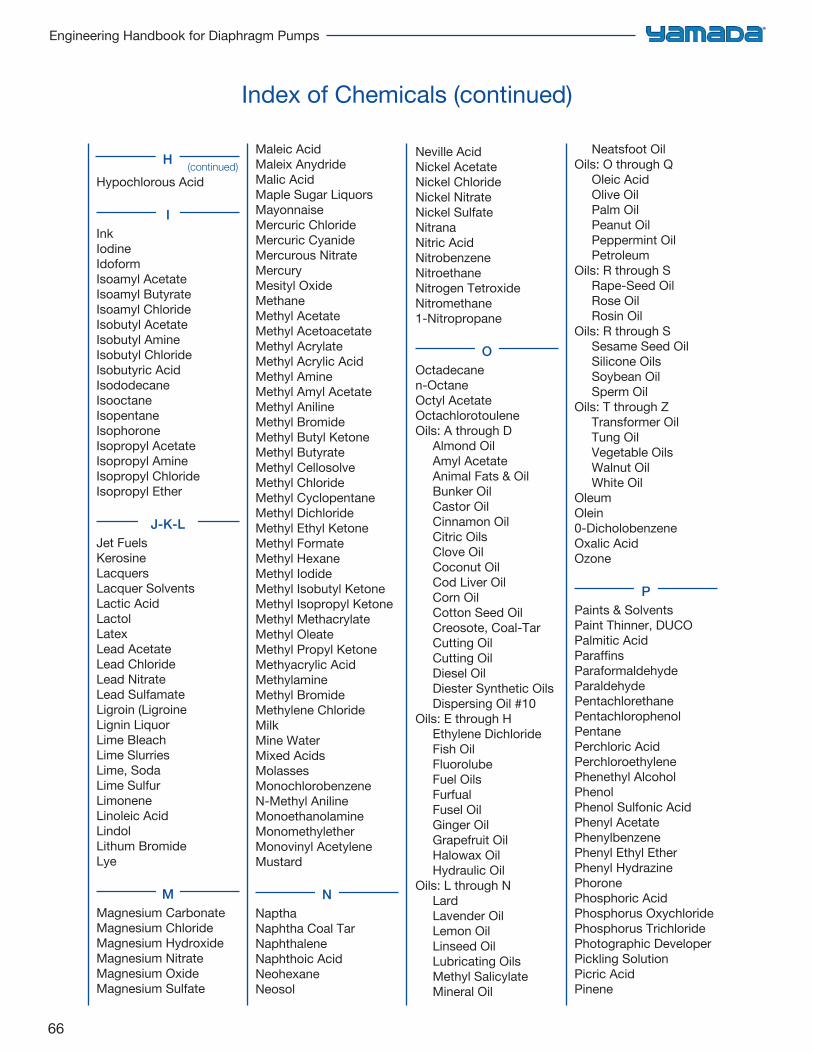
66
Engineering Handbook for Diaphragm Pumps
Index of Chemicals (continued)
Hypochlorous Acid
IInkIodineIdoformIsoamyl AcetateIsoamyl ButyrateIsoamyl ChlorideIsobutyl AcetateIsobutyl AmineIsobutyl ChlorideIsobutyric AcidIsododecaneIsooctaneIsopentaneIsophoroneIsopropyl AcetateIsopropyl AmineIsopropyl ChlorideIsopropyl Ether
J-K-LJet Fuels KerosineLacquersLacquer SolventsLactic AcidLactolLatexLead AcetateLead ChlorideLead NitrateLead SulfamateLigroin (LigroineLignin LiquorLime BleachLime SlurriesLime, SodaLime SulfurLimoneneLinoleic AcidLindolLithum BromideLye
MMagnesium CarbonateMagnesium ChlorideMagnesium HydroxideMagnesium NitrateMagnesium OxideMagnesium Sulfate
Maleic AcidMaleix AnydrideMalic AcidMaple Sugar LiquorsMayonnaiseMercuric ChlorideMercuric CyanideMercurous NitrateMercuryMesityl OxideMethaneMethyl AcetateMethyl AcetoacetateMethyl AcrylateMethyl Acrylic AcidMethyl AmineMethyl Amyl AcetateMethyl AnilineMethyl BromideMethyl Butyl KetoneMethyl ButyrateMethyl CellosolveMethyl ChlorideMethyl CyclopentaneMethyl DichlorideMethyl Ethyl KetoneMethyl FormateMethyl HexaneMethyl IodideMethyl Isobutyl KetoneMethyl Isopropyl KetoneMethyl MethacrylateMethyl OleateMethyl Propyl KetoneMethyacrylic AcidMethylamineMethyl BromideMethylene ChlorideMilkMine WaterMixed AcidsMolassesMonochlorobenzeneN-Methyl AnilineMonoethanolamineMonomethyletherMonovinyl AcetyleneMustard
NNapthaNaphtha Coal TarNaphthaleneNaphthoic AcidNeohexaneNeosol
Neville AcidNickel AcetateNickel ChlorideNickel NitrateNickel SulfateNitranaNitric AcidNitrobenzeneNitroethaneNitrogen TetroxideNitromethane1-Nitropropane
OOctadecanen-OctaneOctyl AcetateOctachlorotouleneOils: A through D
Almond OilAmyl AcetateAnimal Fats & OilBunker OilCastor OilCinnamon OilCitric OilsClove OilCoconut OilCod Liver OilCorn OilCotton Seed OilCreosote, Coal-TarCutting OilCutting OilDiesel OilDiester Synthetic OilsDispersing Oil #10
Oils: E through HEthylene DichlorideFish OilFluorolubeFuel OilsFurfualFusel OilGinger OilGrapefruit OilHalowax OilHydraulic Oil
Oils: L through NLardLavender OilLemon Oil Linseed OilLubricating OilsMethyl SalicylateMineral Oil
Neatsfoot OilOils: O through Q
Oleic AcidOlive OilPalm OilPeanut OilPeppermint OilPetroleum
Oils: R through SRape-Seed OilRose OilRosin Oil
Oils: R through SSesame Seed OilSilicone OilsSoybean OilSperm Oil
Oils: T through ZTransformer OilTung OilVegetable OilsWalnut OilWhite Oil
OleumOlein0-DicholobenzeneOxalic AcidOzone
PPaints & SolventsPaint Thinner, DUCOPalmitic AcidParaffinsParaformaldehydeParaldehydePentachlorethanePentachlorophenolPentanePerchloric AcidPerchloroethylenePhenethyl AlcoholPhenolPhenol Sulfonic AcidPhenyl AcetatePhenylbenzenePhenyl Ethyl EtherPhenyl HydrazinePhoronePhosphoric AcidPhosphorus OxychloridePhosphorus TrichloridePhotographic DeveloperPickling SolutionPicric AcidPinene
(continued)H
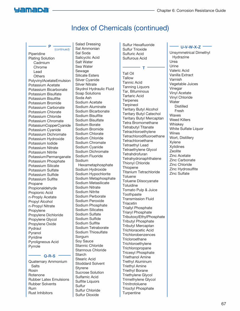
67
Chapter 6: Corrosion Resistance Guide
Index of Chemicals (continued)
PiperidinePlating Solution
CadmiumChromeLeadOthers
Polyvinyl Acetate EmulsionPotassium AcetatePotassium BicarbonatePotassium BisulfatePotassium BisulfitePotassium BromidePotassium CarbonatePotassium ChloratePotassium ChloridePotassium ChromatePotassium Copper CyanidePotassium CyanidePotassium DichromatePotassium HydroxidePotassium IodidePotassium NitratePotassium NitritePotassium PermanganatePotassium PhosphatePotassium SilicatePotassium SulfatePotassium SulfidePotassium SulfitePropanePropionaldehydePropionic Acidn-Proply AcetatePropyl Alcoholn-Propyl NitratePropylenePropylene DichloridePropylene GlycolPropylene OxidePydraulPyranolPyridinePyroligneous AcidPyrrole
Q-R-SQuaternary Ammonium
SaltsRosinRotenoneRubber Latex EmulsionsRubber SolventsRumRust Inhibitors
Salad DressingSal AmmonianSal SodaSalicyclic AcidSalt WaterSea WaterSewageSilicate EstersSilver CyanideSilver NitrateSkydrol Hydraulic FluidSoap SolutionsSoda AshSodium AcetateSodium AluminateSodium BicarbonateSodium BisulfiteSodium BisulfateSodium BorateSodium BromideSodium ChlorateSodium ChlorideSodium ChromateSodium CyanideSodium DichromateSodium FluorideSodium
HexametaphosphateSodium HydroxideSodium HypochloriteSodium MetaphosphateSodium MetasilicateSodium NitrateSodium NitriteSodium PerborateSodium PeroxideSodium PhosphateSodium SilicatesSodium SulfateSodium SulfideSodium SulfiteSodium TetraborateSodium ThiosulfateSorgumSoy SauceStannic ChlorideStannous ChlorideStarchStearic AcidStoddard SolventStyreneSucrose SolutionSulfamic AcidSulfite LiquorsSulfurSulfur ChlorideSulfur Dioxide
Sulfur HexafluorideSulfur TrioxideSulfuric AcidSulfurous Acid
TTall OilTallowTannic AcidTanning LiquorsTar, BituminousTartaric AcidTerpenesTerpineolTeritary Butyl AlcoholTeritary Butyl CatecholTeritary Butyl MercaptanTetra BromomethaneTetrabutyl TitanateTetrachloroethyleneTetrachlorodifluoroethaneTetrachloroethaneTetraethyl LeadTetraethylene GlycolTetrahdrofuranTetrahydronaphthaleneThionyl ChlorideThiopeneTitanium TetrachlorideTolueneToluene DiisocyanateToluidineTomato Pulp & JuiceToothpasteTransmission FluidTriacetinTriallyl PhosphateTriaryl PhosphateTributoxyl Ethyl PhosphateTributyl PhosphateTributyl MercaptanTrichloracetic AcidTrichlorobenzencesTricloroethaneTrichloroethyleneTrichloropropaneTricesyl PhosphateTriethanol AmineTrethyl AluminumTriethyl AmineTriethyl BoraneTriethylene GlycolTrimethylene GlycolTrinitrotolueneTrioctyl PhosphateTurpentine
U-V-W-X-ZUnsymmetrical Dimethyl
HydrazineUreaUrineValeric AcidVanilla ExtractVarnishVegetable JuicesVinegarVinyl AcetateVinyl ChlorideWater
DistilledFresh
WaxesWeed KillersWhiskeyWhite Sulfate LiquorWinesWort, DistilleryXyleneXylidinesZeoliteZinc AcetateZinc CarbonateZinc ChlorideZinc HydrosulfiteZinc Sulfate
(continued)P
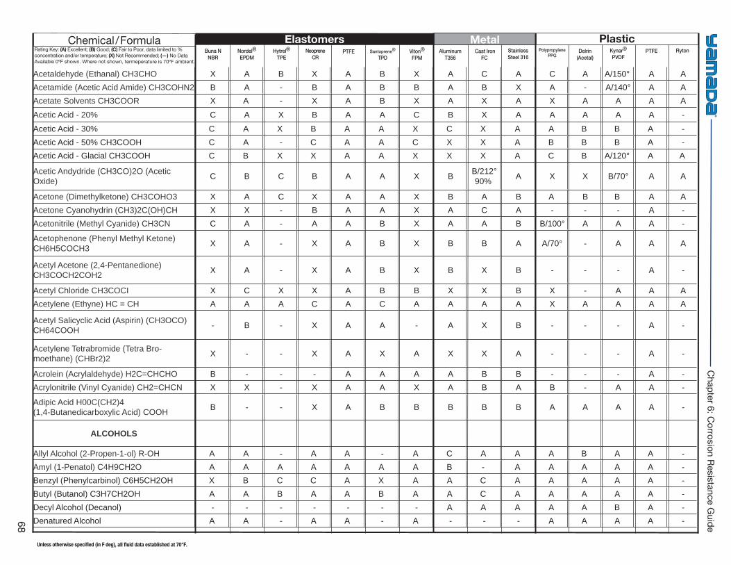
Buna NNBR
Hytrel®
TPE PTFE Viton®
FPM Cast Iron
FC Delrin
(Acetal)PTFENordel®
EPDMNeoprene
CRSantoprene®
TPOAluminum
T356StainlessSteel 316
PolypropylenePPG
Kynar®
PVDFRyton
Elastomers Metal PlasticChemical/FormulaRating Key: (A) Excellent; (B) Good; (C) Fair to Poor, data limited to % concentration and/or temperature; (X) Not Recommended; (—) No Data Available 0ºF shown. Where not shown, termeperature is 70ºF ambient.
Unless otherwise specified (in F deg), all fluid data established at 70°F.
68
Chapter 6: C
orrosion Resistance Guide
Acetaldehyde (Ethanal) CH3CHO X A B X A B X A C A C A A/150° A A Acetamide (Acetic Acid Amide) CH3COHN2 B A - B A B B A B X A - A/140° A A Acetate Solvents CH3COOR X A - X A B X A X A X A A A A
Acetic Acid - 20% C A X B A A C B X A A A A A -
Acetic Acid - 30% C A X B A A X C X A A B B A - Acetic Acid - 50% CH3COOH C A - C A A C X X A B B B A - Acetic Acid - Glacial CH3COOH C B X X A A X X X A C B A/120° A A
Acetic Andydride (CH3CO)2O (Acetic Oxide) C B C B A A X B B/212°
90% A X X B/70° A A
Acetone (Dimethylketone) CH3COHO3 X A C X A A X B A B A B B A A Acetone Cyanohydrin (CH3)2C(OH)CH X X - B A A X A C A - - - A - Acetonitrile (Methyl Cyanide) CH3CN C A - A A B X A A B B/100° A A A -
Acetophenone (Phenyl Methyl Ketone) CH6H5COCH3 X A - X A B X B B A A/70° - A A A
Acetyl Acetone (2,4-Pentanedione) CH3COCH2COH2 X A - X A B X B X B - - - A -
Acetyl Chloride CH3COCI X C X X A B B X X B X - A A A Acetylene (Ethyne) HC = CH A A A C A C A A A A X A A A A
Acetyl Salicyclic Acid (Aspirin) (CH3OCO) CH64COOH - B - X A A - A X B - - - A -
Acetylene Tetrabromide (Tetra Bro-moethane) (CHBr2)2 X - - X A X A X X A - - - A -
Acrolein (Acrylaldehyde) H2C=CHCHO B - - - A A A A B B - - - A - Acrylonitrile (Vinyl Cyanide) CH2=CHCN X X - X A A X A B A B - A A -
Adipic Acid H00C(CH2)4 (1,4-Butanedicarboxylic Acid) COOH B - - X A B B B B B A A A A -
ALCOHOLS
Allyl Alcohol (2-Propen-1-ol) R-OH A A - A A - A C A A A B A A -Amyl (1-Penatol) C4H9CH2O A A A A A A A B - A A A A A -Benzyl (Phenylcarbinol) C6H5CH2OH X B C C A X A A C A A A A A -Butyl (Butanol) C3H7CH2OH A A B A A B A A C A A A A A -Decyl Alcohol (Decanol) - - - - - - - A A A A A B A -Denatured Alcohol A A - A A - A - - - A A A A -
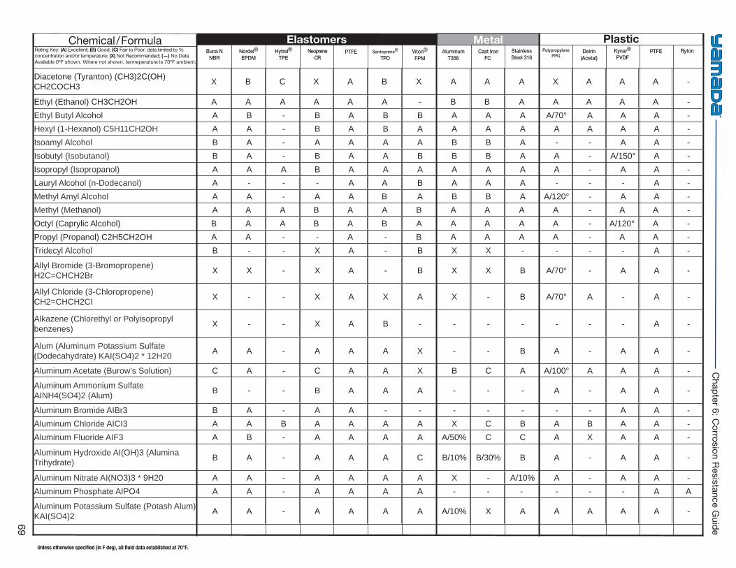
Buna NNBR
Hytrel®
TPE PTFE Viton®
FPM Cast Iron
FC Delrin
(Acetal)PTFENordel®
EPDMNeoprene
CRSantoprene®
TPOAluminum
T356StainlessSteel 316
PolypropylenePPG
Kynar®
PVDFRyton
Elastomers Metal PlasticChemical/FormulaRating Key: (A) Excellent; (B) Good; (C) Fair to Poor, data limited to % concentration and/or temperature; (X) Not Recommended; (—) No Data Available 0ºF shown. Where not shown, termeperature is 70ºF ambient.
Unless otherwise specified (in F deg), all fluid data established at 70°F.
69
Chapter 6: C
orrosion Resistance Guide
Diacetone (Tyranton) (CH3)2C(OH) CH2COCH3 X B C X A B X A A A X A A A -
Ethyl (Ethanol) CH3CH2OH A A A A A A - B B A A A A A -Ethyl Butyl Alcohol A B - B A B B A A A A/70° A A A - Hexyl (1-Hexanol) C5H11CH2OH A A - B A B A A A A A A A A - Isoamyl Alcohol B A - A A A A B B A - - A A - Isobutyl (Isobutanol) B A - B A A B B B A A - A/150° A - Isopropyl (Isopropanol) A A A B A A A A A A A - A A - Lauryl Alcohol (n-Dodecanol) A - - - A A B A A A - - - A - Methyl Amyl Alcohol A A - A A B A B B A A/120° - A A - Methyl (Methanol) A A A B A A B A A A A - A A -Octyl (Caprylic Alcohol) B A A B A B A A A A A - A/120° A - Propyl (Propanol) C2H5CH2OH A A - - A - B A A A A - A A - Tridecyl Alcohol B - - X A - B X X - - - - A -
Allyl Bromide (3-Bromopropene) H2C=CHCH2Br X X - X A - B X X B A/70° - A A -
Allyl Chloride (3-Chloropropene) CH2=CHCH2CI X - - X A X A X - B A/70° A - A -
Alkazene (Chlorethyl or Polyisopropyl benzenes) X - - X A B - - - - - - - A -
Alum (Aluminum Potassium Sulfate (Dodecahydrate) KAI(SO4)2 * 12H20 A A - A A A X - - B A - A A -
Aluminum Acetate (Burow’s Solution) C A - C A A X B C A A/100° A A A -
Aluminum Ammonium Sulfate AINH4(SO4)2 (Alum) B - - B A A A - - - A - A A -
Aluminum Bromide AIBr3 B A - A A - - - - - - - A A - Aluminum Chloride AICI3 A A B A A A A X C B A B A A - Aluminum Fluoride AIF3 A B - A A A A A/50% C C A X A A -
Aluminum Hydroxide AI(OH)3 (Alumina Trihydrate) B A - A A A C B/10% B/30% B A - A A -
Aluminum Nitrate AI(NO3)3 * 9H20 A A - A A A A X - A/10% A - A A - Aluminum Phosphate AIPO4 A A - A A A A - - - - - - A A
Aluminum Potassium Sulfate (Potash Alum) KAI(SO4)2 A A - A A A A A/10% X A A A A A -
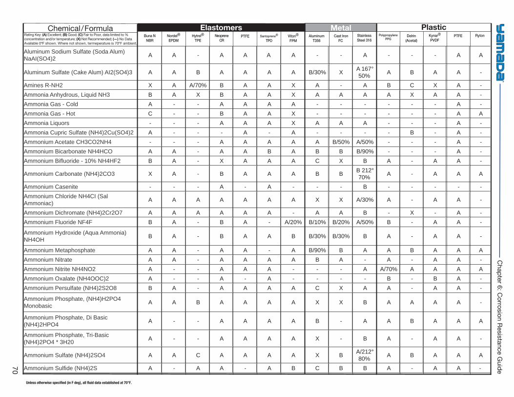
Buna NNBR
Hytrel®
TPE PTFE Viton®
FPM Cast Iron
FC Delrin
(Acetal)PTFENordel®
EPDMNeoprene
CRSantoprene®
TPOAluminum
T356StainlessSteel 316
PolypropylenePPG
Kynar®
PVDFRyton
Elastomers Metal PlasticChemical/FormulaRating Key: (A) Excellent; (B) Good; (C) Fair to Poor, data limited to % concentration and/or temperature; (X) Not Recommended; (—) No Data Available 0ºF shown. Where not shown, termeperature is 70ºF ambient.
Unless otherwise specified (in F deg), all fluid data established at 70°F.
70
Chapter 6: C
orrosion Resistance Guide
Aluminum Sodium Sulfate (Soda Alum) NaAI(SO4)2 A A - A A A A - - A - - - A A
Aluminum Sulfate (Cake Alum) AI2(SO4)3 A A B A A A A B/30% X A 167° 50% A B A A -
Amines R-NH2 X A A/70% B A A X A - A B C X A - Ammonia Anhydrous, Liquid NH3 B A X B A A X A A A A X A A - Ammonia Gas - Cold A - - A A A A - - - - - - A - Ammonia Gas - Hot C - - B A A X - - - - - - A A Ammonia Liquors - - - A A A X A A A - - - A - Ammonia Cupric Sulfate (NH4)2Cu(SO4)2 A - - - A - A - - - - B - A - Ammonium Acetate CH3CO2NH4 - - - A A A A A B/50% A/50% - - - A - Ammonium Bicarbonate NH4HCO A A - A A B A B B B/90% - - - A - Ammonium Bifl uoride - 10% NH4HF2 B A - X A A A C X B A - A A -
Ammonium Carbonate (NH4)2CO3 X A - B A A A B B B 212° 70% A - A A A
Ammonium Casenite - - - A - A - - - B - - - - - Ammonium Chloride NH4CI (Sal Ammoniac) A A A A A A A X X A/30% A - A A -
Ammonium Dichromate (NH4)2Cr2O7 A A A A A A - A A B - X - A - Ammonium Fluoride NF4F B A - B A - A/20% B/10% B/20% A/50% B - A A -
Ammonium Hydroxide (Aqua Ammonia) NH4OH B A - B A A B B/30% B/30% B A - A A -
Ammonium Metaphosphate A A - A A - A B/90% B A A B A A A Ammonium Nitrate A A - A A A A B A - A - A A - Ammonium Nitrite NH4NO2 A - - A A A - - - A A/70% A A A A Ammonium Oxalate (NH4OOC)2 A - - A - A - - - - B - B A - Ammonium Persulfate (NH4)2S2O8 B A - A A A A C X A A - A A -
Ammonium Phosphate, (NH4)H2PO4 Monobasic A A B A A A A X X B A A A A -
Ammonium Phosphate, Di Basic (NH4)2HPO4 A - - A A A A B - A A B A A A
Ammonium Phosphate, Tri-Basic (NH4)2PO4 * 3H20 A - - A A A A X - B A - A A -
Ammonium Sulfate (NH4)2SO4 A A C A A A A X B A/212° 80% A B A A A
Ammonium Sulfi de (NH4)2S A - A A - A B C B B A - A A -
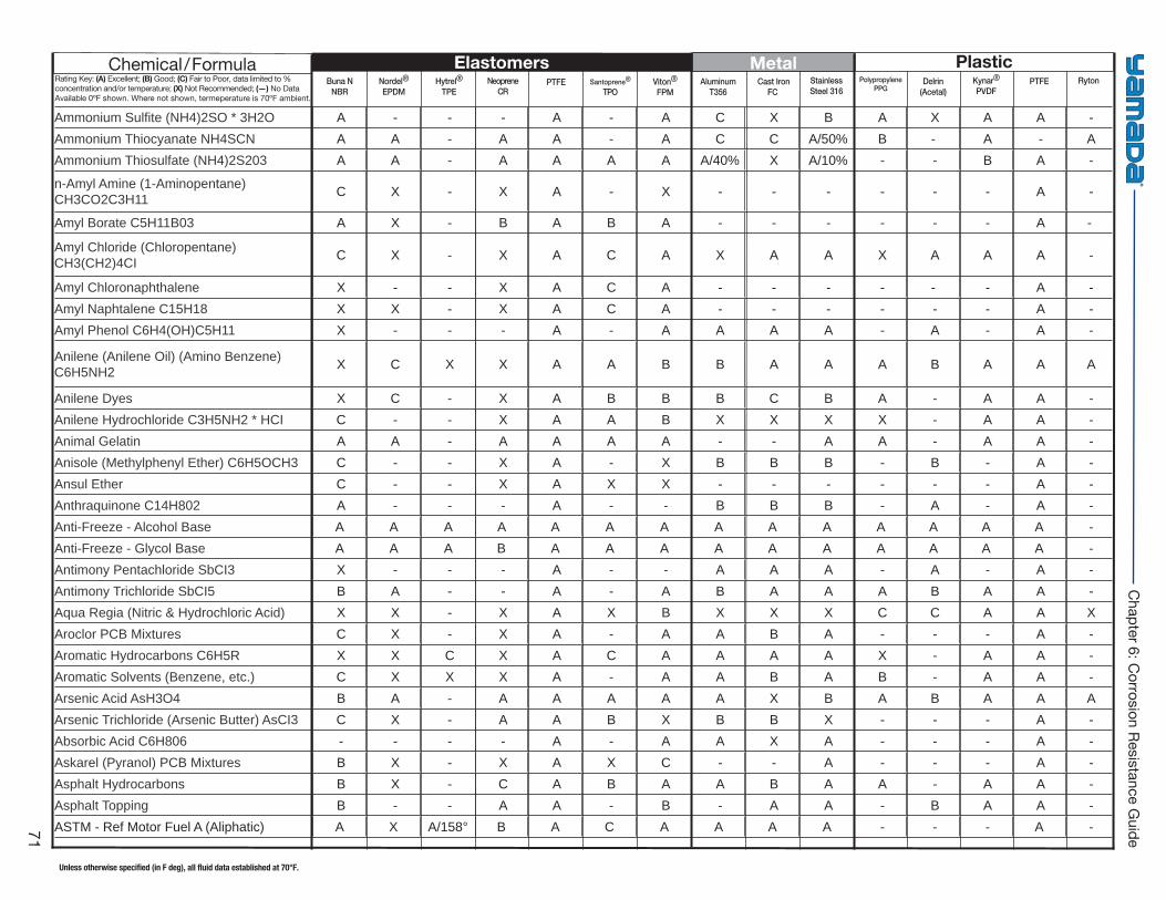
Buna NNBR
Hytrel®
TPE PTFE Viton®
FPM Cast Iron
FC Delrin
(Acetal)PTFENordel®
EPDMNeoprene
CRSantoprene®
TPOAluminum
T356StainlessSteel 316
PolypropylenePPG
Kynar®
PVDFRyton
Elastomers Metal PlasticChemical/FormulaRating Key: (A) Excellent; (B) Good; (C) Fair to Poor, data limited to % concentration and/or temperature; (X) Not Recommended; (—) No Data Available 0ºF shown. Where not shown, termeperature is 70ºF ambient.
Unless otherwise specified (in F deg), all fluid data established at 70°F.
71
Chapter 6: C
orrosion Resistance Guide
Ammonium Sulfi te (NH4)2SO * 3H2O A - - - A - A C X B A X A A - Ammonium Thiocyanate NH4SCN A A - A A - A C C A/50% B - A - A Ammonium Thiosulfate (NH4)2S203 A A - A A A A A/40% X A/10% - - B A -
n-Amyl Amine (1-Aminopentane) CH3CO2C3H11 C X - X A - X - - - - - - A -
Amyl Borate C5H11B03 A X - B A B A - - - - - - A -
Amyl Chloride (Chloropentane) CH3(CH2)4CI C X - X A C A X A A X A A A -
Amyl Chloronaphthalene X - - X A C A - - - - - - A - Amyl Naphtalene C15H18 X X - X A C A - - - - - - A - Amyl Phenol C6H4(OH)C5H11 X - - - A - A A A A - A - A -
Anilene (Anilene Oil) (Amino Benzene) C6H5NH2 X C X X A A B B A A A B A A A
Anilene Dyes X C - X A B B B C B A - A A - Anilene Hydrochloride C3H5NH2 * HCI C - - X A A B X X X X - A A - Animal Gelatin A A - A A A A - - A A - A A - Anisole (Methylphenyl Ether) C6H5OCH3 C - - X A - X B B B - B - A - Ansul Ether C - - X A X X - - - - - - A - Anthraquinone C14H802 A - - - A - - B B B - A - A - Anti-Freeze - Alcohol Base A A A A A A A A A A A A A A - Anti-Freeze - Glycol Base A A A B A A A A A A A A A A -Antimony Pentachloride SbCI3 X - - - A - - A A A - A - A - Antimony Trichloride SbCI5 B A - - A - A B A A A B A A - Aqua Regia (Nitric & Hydrochloric Acid) X X - X A X B X X X C C A A X Aroclor PCB Mixtures C X - X A - A A B A - - - A - Aromatic Hydrocarbons C6H5R X X C X A C A A A A X - A A - Aromatic Solvents (Benzene, etc.) C X X X A - A A B A B - A A - Arsenic Acid AsH3O4 B A - A A A A A X B A B A A A Arsenic Trichloride (Arsenic Butter) AsCI3 C X - A A B X B B X - - - A - Absorbic Acid C6H806 - - - - A - A A X A - - - A - Askarel (Pyranol) PCB Mixtures B X - X A X C - - A - - - A - Asphalt Hydrocarbons B X - C A B A A B A A - A A - Asphalt Topping B - - A A - B - A A - B A A - ASTM - Ref Motor Fuel A (Aliphatic) A X A/158° B A C A A A A - - - A -
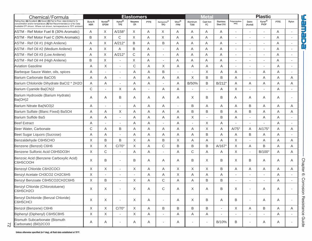
Buna NNBR
Hytrel®
TPE PTFE Viton®
FPM Cast Iron
FC Delrin
(Acetal)PTFENordel®
EPDMNeoprene
CRSantoprene®
TPOAluminum
T356StainlessSteel 316
PolypropylenePPG
Kynar®
PVDFRyton
Elastomers Metal PlasticChemical/FormulaRating Key: (A) Excellent; (B) Good; (C) Fair to Poor, data limited to % concentration and/or temperature; (X) Not Recommended; (—) No Data Available 0ºF shown. Where not shown, termeperature is 70ºF ambient.
Unless otherwise specified (in F deg), all fluid data established at 70°F.
72
Chapter 6: C
orrosion Resistance Guide
ASTM - Ref Motor Fuel B (30% Aromatic) A X A/158° X A X A A A A - - - A - ASTM - Ref Motor Fuel C (50% Aromatic) B X C X A X A A A A - - - A - ASTM - Ref Oil #1 (High Anilene) A X A/212° B A B A A A A - - - A -ASTM - Ref Oil #2 (Medium Anilene) A X A B A - A A A A - - - A - ASTM - Ref Oil #3 (Low Anilene) A X A/212° C A - A A A A - - - A - ASTM - Ref Oil #4 (High Anilene) B X - X A - A A A A - - - A - Aviation Gasoline A X - C A X A A A A - - - A - Barbeque Sauce Water, oils, spices A - - A A B - - X A A - A A - Barium Carbonate BaCO5 A A - A A A A X B B A - A A A Barium Chloloride Dihydrate BaCI2 * 2H2O A A - A A - A B/50% B B/212° A A A A A Barium Cyanide Ba(CN)2 C - X A - A A - - A X - - A -
Barium Hydroxide (Barium Hydrate) Ba(OH)2 A A B A A A A X B B A A A A -
Barium Nitrate Ba(NO3)2 A - - A A A - B A A A B A A A Barium Sulfate (Blanc Fixed) BaSO4 A A X A A A A B B B A B A A A Barium Sulfi de BaS A A - A A A A X - B A - A A - Beef Extract A - - A A - A - X A - - - A - Beer Water, Carbonate C A B A A A A A X A A/75° A A/175° A A Beet Sugar Liquors (Sucrose) A A - A A A A A B A A B A A - Benzaldehyde C6H5CHO X B B X A B X A A A X - A A A Benzene (Benzol) C6H6 X X C/70° X A C B B B A/167° X A B A A Benzene Sulfonic Acid C6H5DO3H X C - A A - A C A A X - B/100° A A
Benzoic Acid (Benzene Carboxylic Acid) C6H5COOH X B - B A A A B X B X B A A A
Benzoyl Chloride C6H2COCI X X - X A A X X X B A A A A A Benzyl Acetate CH3CO2 CH2C6H5 X - - - A A X A A A - - - A - Benzyl Benzoate C6H5CO2CH2C6H5 X B - X A C A A B B - - - A -
Benzyl Chloride (Chlorotoluene) C6H5CH2CI X X - X A C A X A B X - A A -
Benzyl Dichloride (Benzal Chloride) C6H5CHCI X X - X A - A X B A B - A A -
Benzol (Benzene) C6H6 X X C/70° X A B B B B - X A B A A Biphenyl (Diphenyl) C6H5C8H5 X X - X A - A A A - - - - A - Bismuth Subcarbonate (Bismuth Carbonate) (Bi0)2CO3 A A - A A - A - - B/10% B - A A -
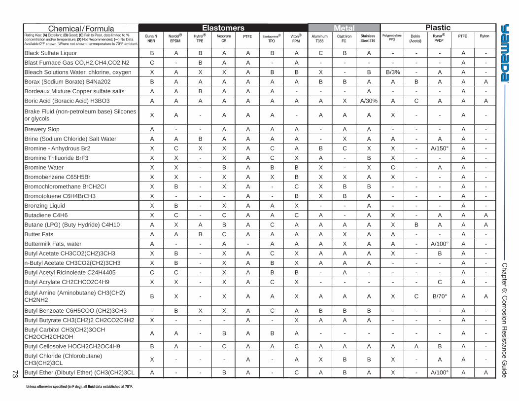
Buna NNBR
Hytrel®
TPE PTFE Viton®
FPM Cast Iron
FC Delrin
(Acetal)PTFENordel®
EPDMNeoprene
CRSantoprene®
TPOAluminum
T356StainlessSteel 316
PolypropylenePPG
Kynar®
PVDFRyton
Elastomers Metal PlasticChemical/FormulaRating Key: (A) Excellent; (B) Good; (C) Fair to Poor, data limited to % concentration and/or temperature; (X) Not Recommended; (—) No Data Available 0ºF shown. Where not shown, termeperature is 70ºF ambient.
Unless otherwise specified (in F deg), all fluid data established at 70°F.
73
Chapter 6: C
orrosion Resistance Guide
Black Sulfate Liquor B A B A A B A C B A - - - A - Blast Furnace Gas CO,H2,CH4,CO2,N2 C - B A A - A - - - - - - A - Bleach Solutions Water, chlorine, oxygen X A X X A B B X - B B/3% - A A - Borax (Sodium Borate) B4Na202 B A A A A A A B B A A B A A A Bordeaux Mixture Copper sulfate salts A A B A A A - - - A - - - A - Boric Acid (Boracic Acid) H3BO3 A A A A A A A A X A/30% A C A A A
Brake Fluid (non-petroleum base) Silcones or glycols X A - A A A - A A A X - - A -
Brewery Slop A - - A A A A - A A - - - A - Brine (Sodium Chloride) Salt Water A A B A A A A - X A A - A A - Bromine - Anhydrous Br2 X C X X A C A B C X X - A/150° A - Bromine Trifl uoride BrF3 X X - X A C X A - B X - - A - Bromine Water X X - B A B B X - X C - A A - Bromobenzene C65H5Br X X - X A X B X X A X - - A - Bromochloromethane BrCH2CI X B - X A - C X B B - - - A - Bromotoluene C6H4BrCH3 X - - - A - B X B A - - - A - Bronzing Liquid X B - X A A X - - A - - - A - Butadiene C4H6 X C - C A A C A - A X - A A A Butane (LPG) (Buty Hydride) C4H10 A X A B A C A A A A X B A A A Butter Fats A A B C A A A A X A A - - A - Buttermilk Fats, water A - - A - A A A X A A - A/100° A - Butyl Acetate CH3CO2(CH2)3CH3 X B - X A C X A A A X - B A - n-Butyl Acetate CH3CO2(CH2)3CH3 X B - X A B X A A A - - - A - Butyl Acetyl Ricinoleate C24H4405 C C - X A B B - A - - - - A - Butyl Acrylate CH2CHCO2C4H9 X X - X A C X - - - - - C A -
Butyl Amine (Aminobutane) CH3(CH2)CH2NH2 B X - X A A X A A A X C B/70° A A
Butyl Benzoate C6H5COO (CH2)3CH3 - B X X A C A B B B - - - A - Butyl Butyrate CH3(CH2)2 CH2CO2C4H2 X - - - A - X A A A - - - A - Butyl Carbitol CH3(CH2)3OCH CH2OCH2CH2OH A A - B A B A - - - - - - A -
Butyl Cellosolve HOCH2CH2OC4H9 B A - C A A C A A A A A B A - Butyl Chloride (Chlorobutane) CH3(CH2)3CL X - - - A - A X B B X - A A -
Butyl Ether (Dibutyl Ether) (CH3(CH2)3CL A - - B A - C A B A X - A/100° A A
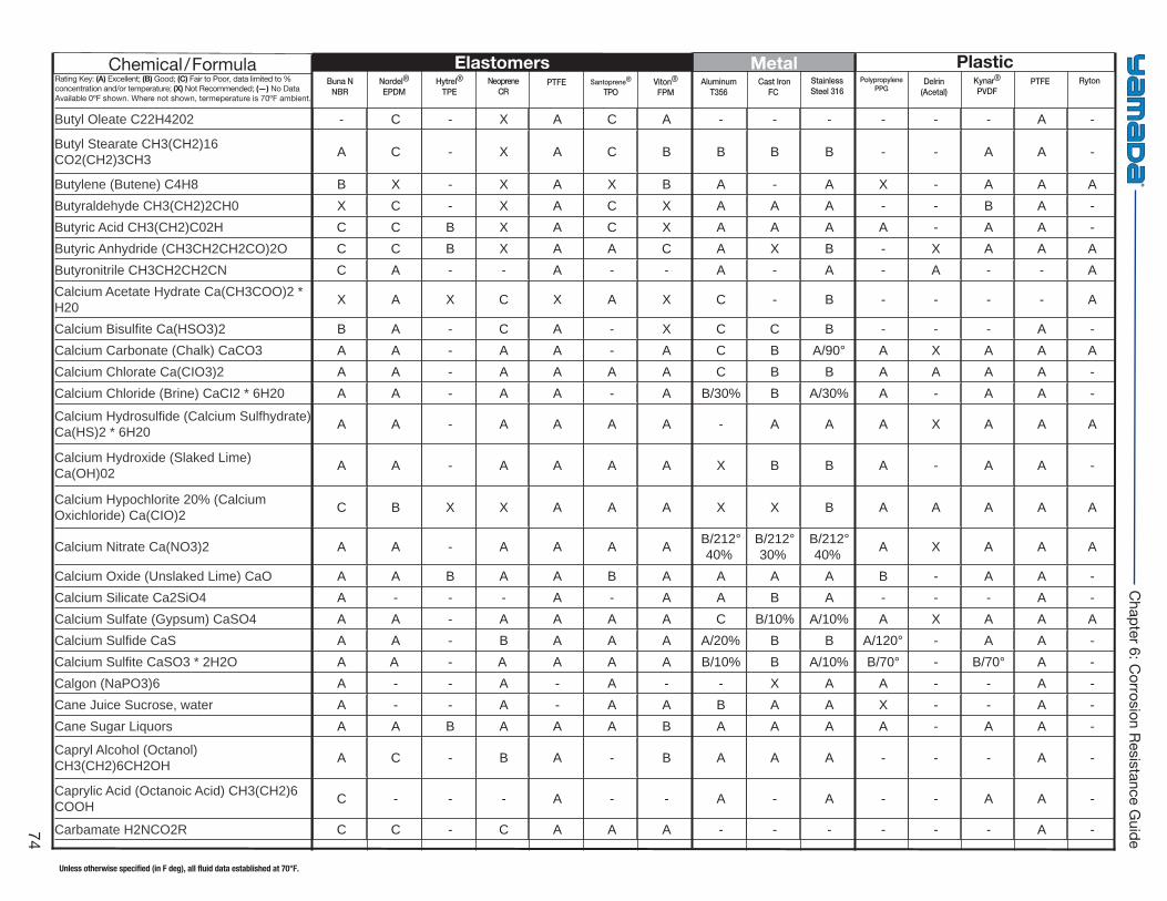
Buna NNBR
Hytrel®
TPE PTFE Viton®
FPM Cast Iron
FC Delrin
(Acetal)PTFENordel®
EPDMNeoprene
CRSantoprene®
TPOAluminum
T356StainlessSteel 316
PolypropylenePPG
Kynar®
PVDFRyton
Elastomers Metal PlasticChemical/FormulaRating Key: (A) Excellent; (B) Good; (C) Fair to Poor, data limited to % concentration and/or temperature; (X) Not Recommended; (—) No Data Available 0ºF shown. Where not shown, termeperature is 70ºF ambient.
Unless otherwise specified (in F deg), all fluid data established at 70°F.
74
Chapter 6: C
orrosion Resistance Guide
Butyl Oleate C22H4202 - C - X A C A - - - - - - A -
Butyl Stearate CH3(CH2)16 CO2(CH2)3CH3 A C - X A C B B B B - - A A -
Butylene (Butene) C4H8 B X - X A X B A - A X - A A A Butyraldehyde CH3(CH2)2CH0 X C - X A C X A A A - - B A - Butyric Acid CH3(CH2)C02H C C B X A C X A A A A - A A - Butyric Anhydride (CH3CH2CH2CO)2O C C B X A A C A X B - X A A A Butyronitrile CH3CH2CH2CN C A - - A - - A - A - A - - A Calcium Acetate Hydrate Ca(CH3COO)2 * H20 X A X C X A X C - B - - - - A
Calcium Bisulfi te Ca(HSO3)2 B A - C A - X C C B - - - A - Calcium Carbonate (Chalk) CaCO3 A A - A A - A C B A/90° A X A A A Calcium Chlorate Ca(CIO3)2 A A - A A A A C B B A A A A - Calcium Chloride (Brine) CaCI2 * 6H20 A A - A A - A B/30% B A/30% A - A A -
Calcium Hydrosulfi de (Calcium Sulfhydrate) Ca(HS)2 * 6H20 A A - A A A A - A A A X A A A
Calcium Hydroxide (Slaked Lime) Ca(OH)02 A A - A A A A X B B A - A A -
Calcium Hypochlorite 20% (Calcium Oxichloride) Ca(CIO)2 C B X X A A A X X B A A A A A
Calcium Nitrate Ca(NO3)2 A A - A A A A B/212° 40%
B/212° 30%
B/212° 40% A X A A A
Calcium Oxide (Unslaked Lime) CaO A A B A A B A A A A B - A A - Calcium Silicate Ca2SiO4 A - - - A - A A B A - - - A - Calcium Sulfate (Gypsum) CaSO4 A A - A A A A C B/10% A/10% A X A A A Calcium Sulfi de CaS A A - B A A A A/20% B B A/120° - A A - Calcium Sulfi te CaSO3 * 2H2O A A - A A A A B/10% B A/10% B/70° - B/70° A - Calgon (NaPO3)6 A - - A - A - - X A A - - A - Cane Juice Sucrose, water A - - A - A A B A A X - - A - Cane Sugar Liquors A A B A A A B A A A A - A A -
Capryl Alcohol (Octanol) CH3(CH2)6CH2OH A C - B A - B A A A - - - A -
Caprylic Acid (Octanoic Acid) CH3(CH2)6 COOH C - - - A - - A - A - - A A -
Carbamate H2NCO2R C C - C A A A - - - - - - A -
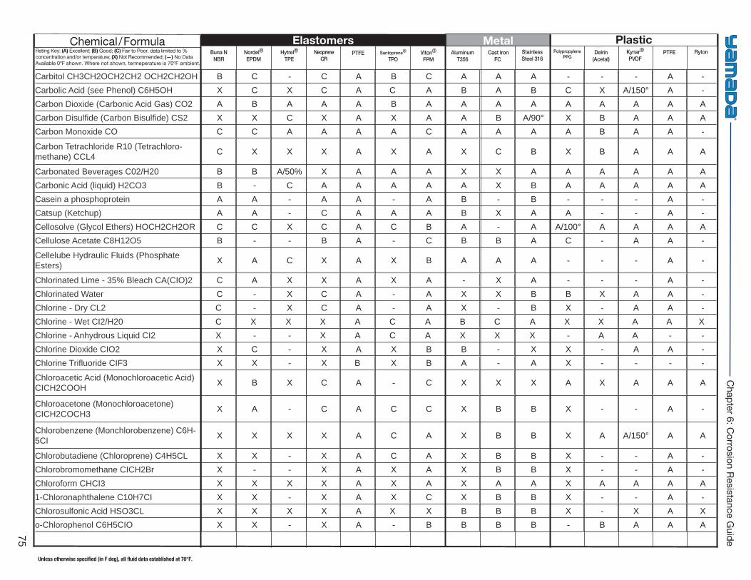
Buna NNBR
Hytrel®
TPE PTFE Viton®
FPM Cast Iron
FC Delrin
(Acetal)PTFENordel®
EPDMNeoprene
CRSantoprene®
TPOAluminum
T356StainlessSteel 316
PolypropylenePPG
Kynar®
PVDFRyton
Elastomers Metal PlasticChemical/FormulaRating Key: (A) Excellent; (B) Good; (C) Fair to Poor, data limited to % concentration and/or temperature; (X) Not Recommended; (—) No Data Available 0ºF shown. Where not shown, termeperature is 70ºF ambient.
Unless otherwise specified (in F deg), all fluid data established at 70°F.
75
Chapter 6: C
orrosion Resistance Guide
Carbitol CH3CH2OCH2CH2 OCH2CH2OH B C - C A B C A A A - - - A - Carbolic Acid (see Phenol) C6H5OH X C X C A C A B A B C X A/150° A - Carbon Dioxide (Carbonic Acid Gas) CO2 A B A A A B A A A A A A A A A Carbon Disulfi de (Carbon Bisulfi de) CS2 X X C X A X A A B A/90° X B A A A Carbon Monoxide CO C C A A A A C A A A A B A A -
Carbon Tetrachloride R10 (Tetrachloro-methane) CCL4 C X X X A X A X C B X B A A A
Carbonated Beverages C02/H20 B B A/50% X A A A X X A A A A A A Carbonic Acid (liquid) H2CO3 B - C A A A A A X B A A A A A Casein a phosphoprotein A A - A A - A B - B - - - A - Catsup (Ketchup) A A - C A A A B X A A - - A - Cellosolve (Glycol Ethers) HOCH2CH2OR C C X C A C B A - A A/100° A A A A Cellulose Acetate C8H12O5 B - - B A - C B B A C - A A -
Cellelube Hydraulic Fluids (Phosphate Esters) X A C X A X B A A A - - - A -
Chlorinated Lime - 35% Bleach CA(CIO)2 C A X X A X A - X A - - - A - Chlorinated Water C - X C A - A X X B B X A A - Chlorine - Dry CL2 C - X C A - A X - B X - A A - Chlorine - Wet CI2/H20 C X X X A C A B C A X X A A XChlorine - Anhydrous Liquid CI2 X - - X A C A X X X - A A - - Chlorine Dioxide CIO2 X C - X A X B B - X X - A A - Chlorine Trifl uoride CIF3 X X - X B X B A - A X - - - -
Chloroacetic Acid (Monochloroacetic Acid) CICH2COOH X B X C A - C X X X A X A A A
Chloroacetone (Monochloroacetone) CICH2COCH3 X A - C A C C X B B X - - A -
Chlorobenzene (Monchlorobenzene) C6H-5CI X X X X A C A X B B X A A/150° A A
Chlorobutadiene (Chloroprene) C4H5CL X X - X A C A X B B X - - A - Chlorobromomethane CICH2Br X - - X A X A X B B X - - A - Chloroform CHCI3 X X X X A X A X A A X A A A A 1-Chloronaphthalene C10H7CI X X - X A X C X B B X - - A - Chlorosulfonic Acid HSO3CL X X X X A X X B B B X - X A X o-Chlorophenol C6H5CIO X X - X A - B B B B - B A A A
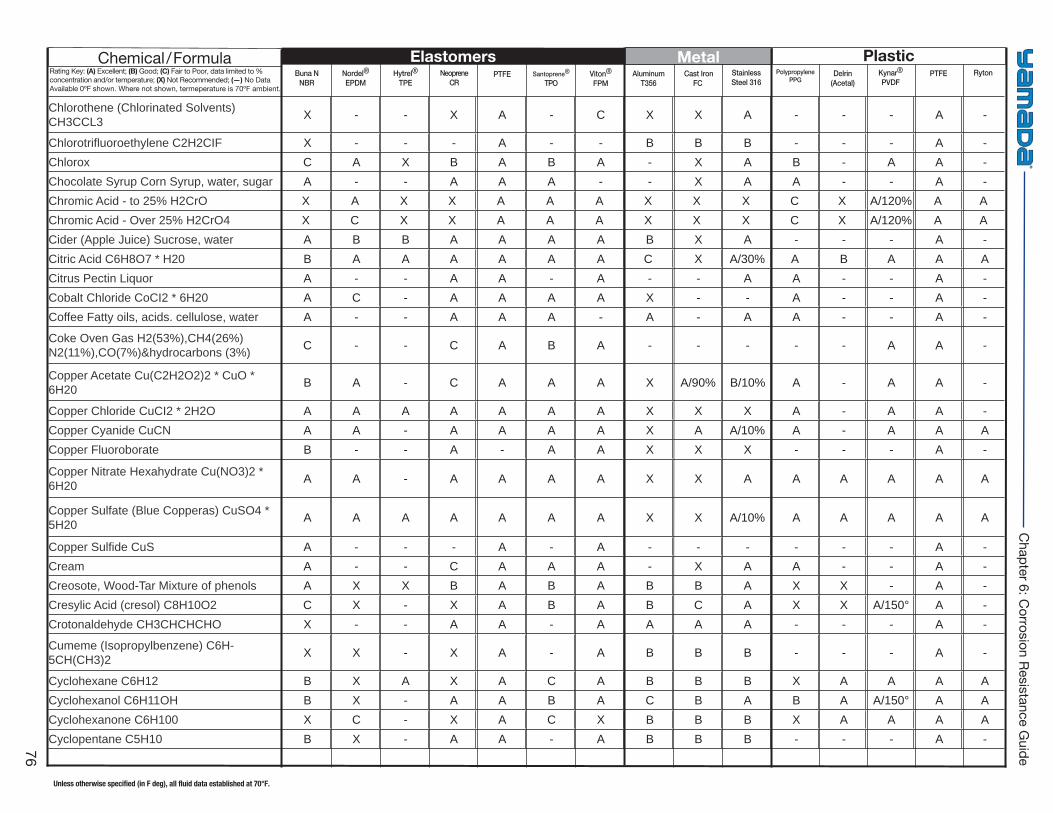
Buna NNBR
Hytrel®
TPE PTFE Viton®
FPM Cast Iron
FC Delrin
(Acetal)PTFENordel®
EPDMNeoprene
CRSantoprene®
TPOAluminum
T356StainlessSteel 316
PolypropylenePPG
Kynar®
PVDFRyton
Elastomers Metal PlasticChemical/FormulaRating Key: (A) Excellent; (B) Good; (C) Fair to Poor, data limited to % concentration and/or temperature; (X) Not Recommended; (—) No Data Available 0ºF shown. Where not shown, termeperature is 70ºF ambient.
Unless otherwise specified (in F deg), all fluid data established at 70°F.
76
Chapter 6: C
orrosion Resistance Guide
Chlorothene (Chlorinated Solvents) CH3CCL3 X - - X A - C X X A - - - A -
Chlorotrifl uoroethylene C2H2CIF X - - - A - - B B B - - - A - Chlorox C A X B A B A - X A B - A A - Chocolate Syrup Corn Syrup, water, sugar A - - A A A - - X A A - - A - Chromic Acid - to 25% H2CrO X A X X A A A X X X C X A/120% A AChromic Acid - Over 25% H2CrO4 X C X X A A A X X X C X A/120% A ACider (Apple Juice) Sucrose, water A B B A A A A B X A - - - A - Citric Acid C6H8O7 * H20 B A A A A A A C X A/30% A B A A A Citrus Pectin Liquor A - - A A - A - - A A - - A - Cobalt Chloride CoCI2 * 6H20 A C - A A A A X - - A - - A - Coffee Fatty oils, acids. cellulose, water A - - A A A - A - A A - - A -
Coke Oven Gas H2(53%),CH4(26%)N2(11%),CO(7%)&hydrocarbons (3%) C - - C A B A - - - - - A A -
Copper Acetate Cu(C2H2O2)2 * CuO * 6H20 B A - C A A A X A/90% B/10% A - A A -
Copper Chloride CuCI2 * 2H2O A A A A A A A X X X A - A A - Copper Cyanide CuCN A A - A A A A X A A/10% A - A A A Copper Fluoroborate B - - A - A A X X X - - - A -
Copper Nitrate Hexahydrate Cu(NO3)2 * 6H20 A A - A A A A X X A A A A A A
Copper Sulfate (Blue Copperas) CuSO4 * 5H20 A A A A A A A X X A/10% A A A A A
Copper Sulfi de CuS A - - - A - A - - - - - - A - Cream A - - C A A A - X A A - - A - Creosote, Wood-Tar Mixture of phenols A X X B A B A B B A X X - A - Cresylic Acid (cresol) C8H10O2 C X - X A B A B C A X X A/150° A - Crotonaldehyde CH3CHCHCHO X - - A A - A A A A - - - A -
Cumeme (Isopropylbenzene) C6H-5CH(CH3)2 X X - X A - A B B B - - - A -
Cyclohexane C6H12 B X A X A C A B B B X A A A A Cyclohexanol C6H11OH B X - A A B A C B A B A A/150° A A Cyclohexanone C6H100 X C - X A C X B B B X A A A A Cyclopentane C5H10 B X - A A - A B B B - - - A -
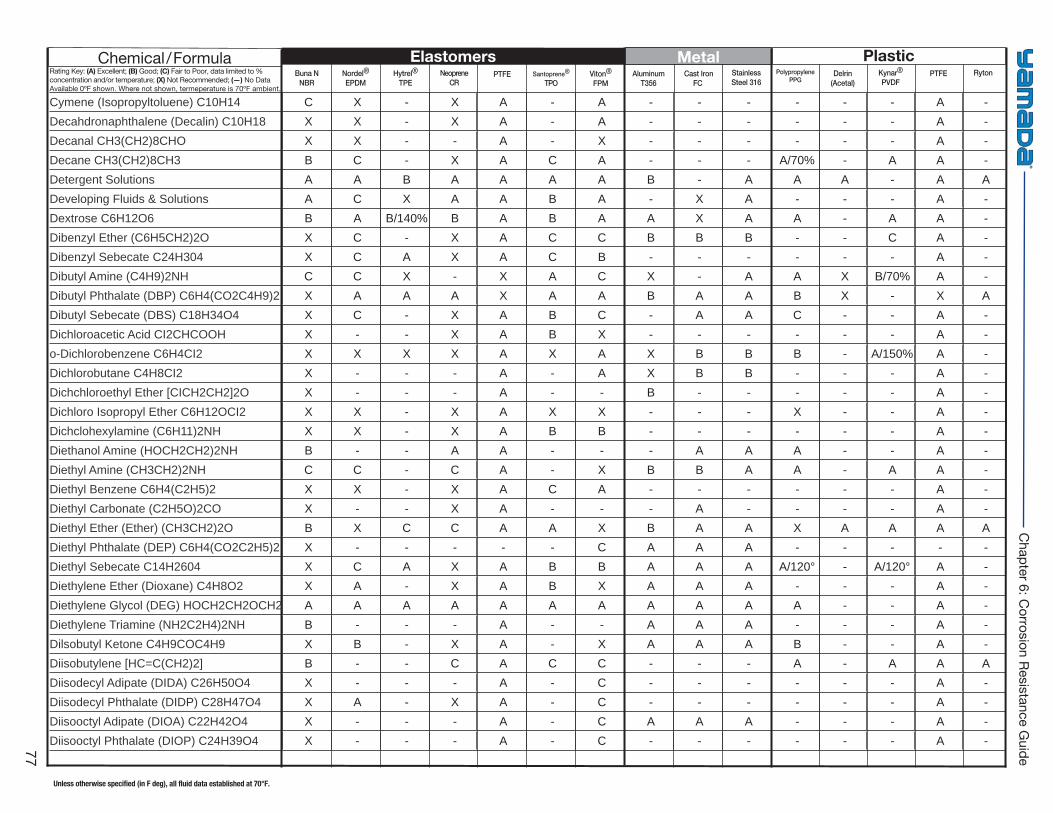
Buna NNBR
Hytrel®
TPE PTFE Viton®
FPM Cast Iron
FC Delrin
(Acetal)PTFENordel®
EPDMNeoprene
CRSantoprene®
TPOAluminum
T356StainlessSteel 316
PolypropylenePPG
Kynar®
PVDFRyton
Elastomers Metal PlasticChemical/FormulaRating Key: (A) Excellent; (B) Good; (C) Fair to Poor, data limited to % concentration and/or temperature; (X) Not Recommended; (—) No Data Available 0ºF shown. Where not shown, termeperature is 70ºF ambient.
Unless otherwise specified (in F deg), all fluid data established at 70°F.
77
Chapter 6: C
orrosion Resistance Guide
Cymene (Isopropyltoluene) C10H14 C X - X A - A - - - - - - A - Decahdronaphthalene (Decalin) C10H18 X X - X A - A - - - - - - A - Decanal CH3(CH2)8CHO X X - - A - X - - - - - - A - Decane CH3(CH2)8CH3 B C - X A C A - - - A/70% - A A - Detergent Solutions A A B A A A A B - A A A - A A Developing Fluids & Solutions A C X A A B A - X A - - - A - Dextrose C6H12O6 B A B/140% B A B A A X A A - A A - Dibenzyl Ether (C6H5CH2)2O X C - X A C C B B B - - C A - Dibenzyl Sebecate C24H304 X C A X A C B - - - - - - A - Dibutyl Amine (C4H9)2NH C C X - X A C X - A A X B/70% A - Dibutyl Phthalate (DBP) C6H4(CO2C4H9)2 X A A A X A A B A A B X - X A Dibutyl Sebecate (DBS) C18H34O4 X C - X A B C - A A C - - A - Dichloroacetic Acid CI2CHCOOH X - - X A B X - - - - - - A - o-Dichlorobenzene C6H4CI2 X X X X A X A X B B B - A/150% A - Dichlorobutane C4H8CI2 X - - - A - A X B B - - - A - Dichchloroethyl Ether [CICH2CH2]2O X - - - A - - B - - - - - A - Dichloro Isopropyl Ether C6H12OCI2 X X - X A X X - - - X - - A - Dichclohexylamine (C6H11)2NH X X - X A B B - - - - - - A - Diethanol Amine (HOCH2CH2)2NH B - - A A - - - A A A - - A - Diethyl Amine (CH3CH2)2NH C C - C A - X B B A A - A A - Diethyl Benzene C6H4(C2H5)2 X X - X A C A - - - - - - A - Diethyl Carbonate (C2H5O)2CO X - - X A - - - A - - - - A - Diethyl Ether (Ether) (CH3CH2)2O B X C C A A X B A A X A A A A Diethyl Phthalate (DEP) C6H4(CO2C2H5)2 X - - - - - C A A A - - - - - Diethyl Sebecate C14H2604 X C A X A B B A A A A/120° - A/120° A - Diethylene Ether (Dioxane) C4H8O2 X A - X A B X A A A - - - A - Diethylene Glycol (DEG) HOCH2CH2OCH2 A A A A A A A A A A A - - A - Diethylene Triamine (NH2C2H4)2NH B - - - A - - A A A - - - A - Dilsobutyl Ketone C4H9COC4H9 X B - X A - X A A A B - - A - Diisobutylene [HC=C(CH2)2] B - - C A C C - - - A - A A A Diisodecyl Adipate (DIDA) C26H50O4 X - - - A - C - - - - - - A - Diisodecyl Phthalate (DIDP) C28H47O4 X A - X A - C - - - - - - A - Diisooctyl Adipate (DIOA) C22H42O4 X - - - A - C A A A - - - A - Diisooctyl Phthalate (DIOP) C24H39O4 X - - - A - C - - - - - - A -
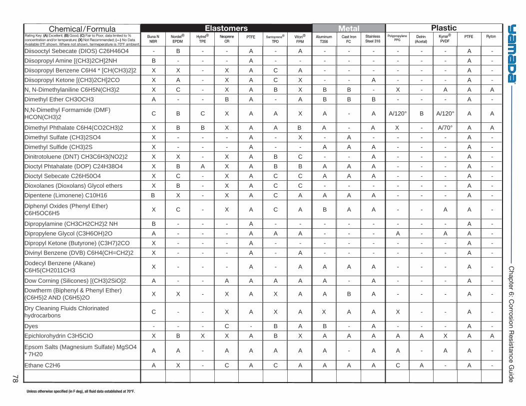
Buna NNBR
Hytrel®
TPE PTFE Viton®
FPM Cast Iron
FC Delrin
(Acetal)PTFENordel®
EPDMNeoprene
CRSantoprene®
TPOAluminum
T356StainlessSteel 316
PolypropylenePPG
Kynar®
PVDFRyton
Elastomers Metal PlasticChemical/FormulaRating Key: (A) Excellent; (B) Good; (C) Fair to Poor, data limited to % concentration and/or temperature; (X) Not Recommended; (—) No Data Available 0ºF shown. Where not shown, termeperature is 70ºF ambient.
Unless otherwise specified (in F deg), all fluid data established at 70°F.
78
Chapter 6: C
orrosion Resistance Guide
Diisooctyl Sebecate (DIOS) C26H46O4 - B - - A - A - - - - - - A - Diisopropyl Amine [(CH3)2CH]2NH B - - - A - - - - - - - - A - Diisopropyl Benzene C6H4 * [CH(CH3)2]2 X X - X A C A - - - - - - A - Diisopropyl Ketone [(CH3)2CH]2CO X A - X A C X - - A - - - A - N, N-Dimethylaniline C6H5N(CH3)2 X C - X A B X B B - X - A A A Dimethyl Ether CH3OCH3 A - - B A - A B B B - - - A -
N,N-Dimethyl Formamide (DMF) HCON(CH3)2 C B C X A A X A - A A/120° B A/120° A A
Dimethyl Phthalate C6H4(CO2CH3)2 X B B X A A B A - A X - A/70° A A Dimethyl Sulfate (CH3)2SO4 X - - - A - X - A - - - - A - Dimethyl Sulfi de (CH3)2S X - - - A - - A A A - - - A - Dinitrotoluene (DNT) CH3C6H3(NO2)2 X X - X A B C - - A - - - A - Dioctyl Phtahalate (DOP) C24H38O4 X B A X A B B A A A - - - A - Dioctyl Sebecate C26H50O4 X C - X A C C A A A - - - A - Dioxolanes (Dioxolans) Glycol ethers X B - X A C C - - - - - - A - Dipentene (Limonene) C10H16 B X - X A C A A A A - - - A -
Diphenyl Oxides (Phenyl Ether) C6H5OC6H5 X C - X A C A B A A - - A A -
Dipropylamine (CH3CH2CH2)2 NH B - - - A - - - - - - - - A - Dipropylene Glycol (C3H6OH)2O A - - - A A A - - - A - A A - Dipropyl Ketone (Butyrone) (C3H7)2CO X - - - A - - - - - - - - A - Divinyl Benzene (DVB) C6H4(CH=CH2)2 X - - - A - A - - - - - - A -
Dodecyl Benzene (Alkane) C6H5(CH2011CH3 X - - - A - A A A A - - - A -
Dow Corning (Silicones) [(CH3)2SiO]2 A - - A A A A A - A - - - A - Dowtherm (Biphenyl & Phenyl Ether) (C6H5)2 AND (C6H5)2O X X - X A X A A B A - - - A -
Dry Cleaning Fluids Chlorinated hydrocarbons C - - X A X A X A A X - - A -
Dyes - - - C - B A B - A - - - A - Epichlorohydrin C3H5CIO X B X X A B X A A A A A X A A
Epsom Salts (Magnesium Sulfate) MgSO4 * 7H20 A A - A A A A A - A A - A A -
Ethane C2H6 A X - C A C A A A A C A - A -
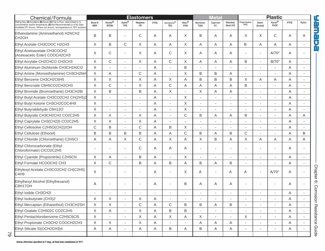
Buna NNBR
Hytrel®
TPE PTFE Viton®
FPM Cast Iron
FC Delrin
(Acetal)PTFENordel®
EPDMNeoprene
CRSantoprene®
TPOAluminum
T356StainlessSteel 316
PolypropylenePPG
Kynar®
PVDFRyton
Elastomers Metal PlasticChemical/FormulaRating Key: (A) Excellent; (B) Good; (C) Fair to Poor, data limited to % concentration and/or temperature; (X) Not Recommended; (—) No Data Available 0ºF shown. Where not shown, termeperature is 70ºF ambient.
Unless otherwise specified (in F deg), all fluid data established at 70°F.
79
Chapter 6: C
orrosion Resistance Guide
Ethanolamine (Aminoethanol) H2NCH2 CH2OH B B - C A A X B A A X X C A A
Ethyl Acetate CH3COOC H2CH3 X B C X A A X A A A B A A A -
Ethyl Acetoacetate CH3COCH2 (Acetoacetic Ester) COOCH2CH3 X C - X A C X A A A - - A/70° A -
Ethyl Acrylate CH2CHCO CH2CH3 X C - X A C X A A A B - B/70° A - Ethyl Aluminum Dichloride CH3CH2AICI2 X - - - A - B - - - - - - A - Ethyl Amine (Monoethylamine) CH3CH2NH X A - C A - X B B A - - - A - Ethyl Benzene CH3CH2C6H5 X X - X A X A B B B X A A A - Ethyl Benzoate C6H5CO2CH2CH3 X C - X A C A A A A B - - A - Ethyl Bromide (Bromoethane) CH3CH2Br X B - B A X - X A A - - - A - Ethyl Butyl Acetate CH3CO2CH2 CH(2H5)2 X - - - A - X - - - - - - A - Ethyl Butyl Ketone CH3CH2COC4H9 X - - - A - X - - - - - - A - Ethyl Butyraldehyde C6H12O X - - - A - X - - - - - - A - Ethyl Butyrate CH3CH2CH2 CO2C2H5 X X - X A - C B A A B - - A A Ethyl Caprylate CH3(CH2)5 CO2C2H5 X X - X A - - - - - - - - A - Ethyl Cellosolve C2H5O(CH2)2OH C B - C A B X - - - - - - A - Ethyl Cellulose (Ethocel) B B B B A A C B A B C - - A B Ethyl Chloride (Chloroethane) C2H5CI A A X C A X A X B A X A A A A
Ethyl Chlorocarbonate (Ethyl Chloroformate) CICO2C2H5 - - - C A A A - - - - - - A -
Ethyl Cyanide (Propionitrile) C2H5CN X A - B A - X - - - - - - A - Ethyl Formate HCOOCH2 CH3 X C - B A B A B A B - - - A -
Ethylexyl Acetate CH3CO2CH2 CH(C2H5)C4H9 X - - - A - X A - A A - A/70° A -
Ethylhexyl Alcohol (Ethylhexanol) C8H17OH A - - - A - B A A A - - - A -
Ethyl Iodide CH3CH2I - - - - - - - - - - - - - A - Ethyl Isobutyrate (CH3)2 X X - X A - - - - - - - - A - Ethyl Mercaptan (Ethanethiol) CH3CH2SH X X - C A C B B A B - - - A - Ethyl Oxalate C2H502C CO2C2H5 X A - X A B B - - - - - - A - Ethyl Pentachlorobenzene C2H5C6CI5 X - - X A X A X - - X - - A - Ethyl Propionate CH3CH2 COOCH2CH3 X X - X A - - A A A - - - A - Ethyl Silicate Si(OCH2CH3)4 A A - A A B A B A A - - - A -
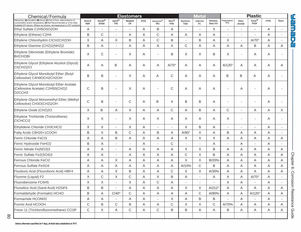
Buna NNBR
Hytrel®
TPE PTFE Viton®
FPM Cast Iron
FC Delrin
(Acetal)PTFENordel®
EPDMNeoprene
CRSantoprene®
TPOAluminum
T356StainlessSteel 316
PolypropylenePPG
Kynar®
PVDFRyton
Elastomers Metal PlasticChemical/FormulaRating Key: (A) Excellent; (B) Good; (C) Fair to Poor, data limited to % concentration and/or temperature; (X) Not Recommended; (—) No Data Available 0ºF shown. Where not shown, termeperature is 70ºF ambient.
Unless otherwise specified (in F deg), all fluid data established at 70°F.
80
Chapter 6: C
orrosion Resistance Guide
Ethyl Sulfate C2H5OSO2OH A - - - A B A - - X - - - A - Ethylene (Ethene) C2H4 B C - A A C A A A A - - - A - Ethylene Chlorohydrin CICH2CH2OH X A X B A C B - B A X - A/70° A - Ethylene Diamine (CH2)2(NH2)2 B A - A A A X C A A A A B A A
Ethylene Dibromide (Ethylene Bromide) Br(CH2)Br X C - X A - B X X B X - A A -
Ethylene Glycol (Ethylene Alcohol (Glycol) CI(CH2)2CI A A B A A A A/70° A A A A/120° A A A A
Ethylene Glycol Monobutyl Ether (Butyl Cellosolve) C4H9OCH2CH2OH B B - X A A C A A A B B A A -
Ethylene Glycol Monobutyl Ether Acetate (Cellosolve Acetate) C2H50(CH2)2 O2CCH3
C B - X A - C A A A - A - A -
Ethylene Glycol Monomethyl Ether (Methyl Cellosolve) CH3O(CH2)2OH C B - C A B X B B A - - - A -
Ethylene Oxide (CH2)2O X B A X A A C A B A C - A A X
Ethylene Trichloride (Triclorothene) CICHCCI2 X X - X A X A X A A X - - A -
Ethylidene Chloride CH3CHCI2 X X - X A - - X B A - - - A - Fatty Acids C8H20+1COOH B X B C A B A A/90° X A B A A A - Ferric Chloride FeCI3 A A B A A A A X X X A A A A A Ferric Hydroxide FeHO2 B A - - A - C - - A - A - A - Ferric Nitrate Fe(NO3)3 A A - A A A A X X B A A A A A Ferric Sulfate Fe2(SO4)3 A A - A A A A C X B A A A A A Ferrous Chloride FeCI2 A A X A A A A X X B/20% A A A A A Ferrous Sulfate FeSO4 A A A A A A A A/10% C B A A A A A Fluoboric Acid (Flouroboric Acid) HBF4 A A X B A A C X X A/30% A A A A A Fluorine (Liquid) F2 X C X C A X B A - A X A A/70° A - Fluorobenzene FC6H5 X X - X A C A - - - X A - A - Fluosilicic Acid (Sand Acid) H2SiF6 B B - A A A A X X A/212° A A A A A Formaldehyde (Formalin) HCHO B A C/40° C A A A A C A/90% A A A/120° A A Formamide HCONH2 A A - A A - X A B B - A - A - Formic Acid HCOOH C B C B A A C X X C A/70% A A A A Freon 11 (Trichlorofl uoromethane) CCI3F C X A C A C B B A A B A A A A
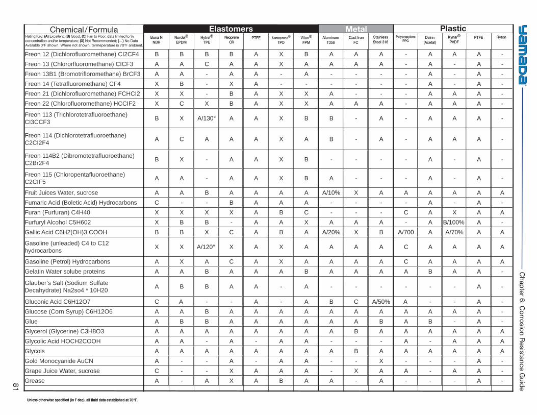
Buna NNBR
Hytrel®
TPE PTFE Viton®
FPM Cast Iron
FC Delrin
(Acetal)PTFENordel®
EPDMNeoprene
CRSantoprene®
TPOAluminum
T356StainlessSteel 316
PolypropylenePPG
Kynar®
PVDFRyton
Elastomers Metal PlasticChemical/FormulaRating Key: (A) Excellent; (B) Good; (C) Fair to Poor, data limited to % concentration and/or temperature; (X) Not Recommended; (—) No Data Available 0ºF shown. Where not shown, termeperature is 70ºF ambient.
Unless otherwise specified (in F deg), all fluid data established at 70°F.
81
Chapter 6: C
orrosion Resistance Guide
Freon 12 (Dichlorofl uoromethane) CI2CF4 B B B B A X B A A A - A A A - Freon 13 (Chlororfl uoromethane) CICF3 A A C A A X A A A A - A - A - Freon 13B1 (Bromotrifl oromethane) BrCF3 A A - A A - A - - - - A - A - Freon 14 (Tetrafl uoromethane) CF4 X B - X A - - - - - - A - A - Freon 21 (Dichlorofl uoromethane) FCHCI2 X X - B A X X A - - - A A A - Freon 22 (Chlorofl uoromethane) HCCIF2 X C X B A X X A A A - A A A -
Freon 113 (Trichlorotetrafl uoroethane) CI3CCF3 B X A/130° A A X B B - A - A A A -
Freon 114 (Dichlorotetrafl uoroethane) C2CI2F4 A C A A A X A B - A - A A A -
Freon 114B2 (Dibromotetrafl uoroethane) C2Br2F4 B X - A A X B - - - - A - A -
Freon 115 (Chloropentafl uoroethane) C2CIF5 A A - A A X B A - - - A - A -
Fruit Juices Water, sucrose A A B A A A A A/10% X A A A A A A Fumaric Acid (Boletic Acid) Hydrocarbons C - - B A A A - - - - A - A - Furan (Furfuran) C4H40 X X X X A B C - - - C A X A A Furfuryl Alcohol C5H602 X B B - A A X A A A - A B/100% A - Gallic Acid C6H2(OH)3 COOH B B X C A B A A/20% X B A/700 A A/70% A A
Gasoline (unleaded) C4 to C12 hydrocarbons X X A/120° X A X A A A A C A A A A
Gasoline (Petrol) Hydrocarbons A X A C A X A A A A C A A A A Gelatin Water solube proteins A A B A A A B A A A A B A A -
Glauber’s Salt (Sodium Sulfate Decahydrate) Na2so4 * 10H20 A B B A A - A - - - - - - A -
Gluconic Acid C6H12O7 C A - - A - A B C A/50% A - - A - Glucose (Corn Syrup) C6H12O6 A A B A A A A A A A A A A A - Glue A B B A A A A A A B A B - A - Glycerol (Glycerine) C3H8O3 A A A A A A A A B A A A A A A Glycolic Acid HOCH2COOH A A - A - A A - - - A - A A A Glycols A A A A A A A A B A A A A A A Gold Monocyanide AuCN A - - A - A A - - X - - - A - Grape Juice Water, sucrose C - - X A A A - X A A - A A - Grease A - A X A B A A - A - - - A -
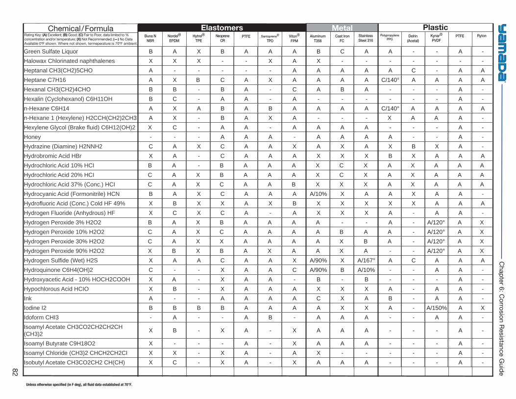
Buna NNBR
Hytrel®
TPE PTFE Viton®
FPM Cast Iron
FC Delrin
(Acetal)PTFENordel®
EPDMNeoprene
CRSantoprene®
TPOAluminum
T356StainlessSteel 316
PolypropylenePPG
Kynar®
PVDFRyton
Elastomers Metal PlasticChemical/FormulaRating Key: (A) Excellent; (B) Good; (C) Fair to Poor, data limited to % concentration and/or temperature; (X) Not Recommended; (—) No Data Available 0ºF shown. Where not shown, termeperature is 70ºF ambient.
Unless otherwise specified (in F deg), all fluid data established at 70°F.
82
Chapter 6: C
orrosion Resistance Guide
Green Sulfate Liquor B A X B A A A B C A A - - A - Halowax Chlorinated naphthalenes X X X - - X A X - - - - - - - Heptanal CH3(CH2)5CHO A - - - - - A A A A A C - A A Heptane C7H16 A X B C A X A A A A C/140° A A A A Hexanal CH3(CH2)4CHO B B - B A - C A B A - - - A - Hexalin (Cyclohexanol) C6H11OH B C - A A - A - - - - - - A - n-Hexane C6H14 A X A B A B A A A A C/140° A A A A n-Hexane 1 (Hexylene) H2CCH(CH2)2CH3 A X - B A X A - - - X A A A - Hexylene Glycol (Brake fl uid) C6H12(OH)2 X C - A A - A A A A - - - A - Honey - - - A A A - A A A A - - A - Hydrazine (Diamine) H2NNH2 C A X C A A X A X A X B X A - Hydrobromic Acid HBr X A - C A A A X X X B X A A A Hydrochloric Acid 10% HCI B A - B A A A X C X A X A A AHydrochloric Acid 20% HCI C A X B A A A X C X A X A A AHydrochloric Acid 37% (Conc.) HCI C A X C A A B X X X A X A A AHydrocyanic Acid (Formonitrile) HCN B A X C A A A A/10% X A A X A A - Hydrofl uoric Acid (Conc.) Cold HF 49% X B X X A X B X X X X X A A A Hydrogen Fluoride (Anhydrous) HF X C X C A - A X X X A - A A - Hydrogen Peroxide 3% H2O2 B A X B A A A A - - A - A/120° A XHydrogen Peroxide 10% H2O2 C A X C A A A A B A A - A/120° A XHydrogen Peroxide 30% H2O2 C A X X A A A A X B A - A/120° A XHydrogen Peroxide 90% H2O2 X B X B A X A A X A - - A/120° A XHydrogen Sulfi de (Wet) H2S X A A C A A X A/90% X A/167° A C A A A Hydroquinone C6H4(OH)2 C - - X A A C A/90% B A/10% - - A A - Hydroxyacetic Acid - 10% HOCH2COOH X A - X A A - B - B - - - A - Hypochlorous Acid HCIO X B - X A A A X X X A - A A - Ink A - - A A A A C X A B - A A - Iodine I2 B B B B A A A A X X A - A/150% A X Idoform CHI3 - A - - A B - A A A - - A A - Isoamyl Acetate CH3CO2CH2CH2CH (CH3)2 X B - X A - X A A A - - - A -
Isoamyl Butyrate C9H18O2 X - - - A - X A A A - - - A - Isoamyl Chloride (CH3)2 CHCH2CH2CI X X - X A - A X - - - - - A - Isobutyl Acetate CH3CO2CH2 CH(CH) X C - X A - X A A A - - - A -
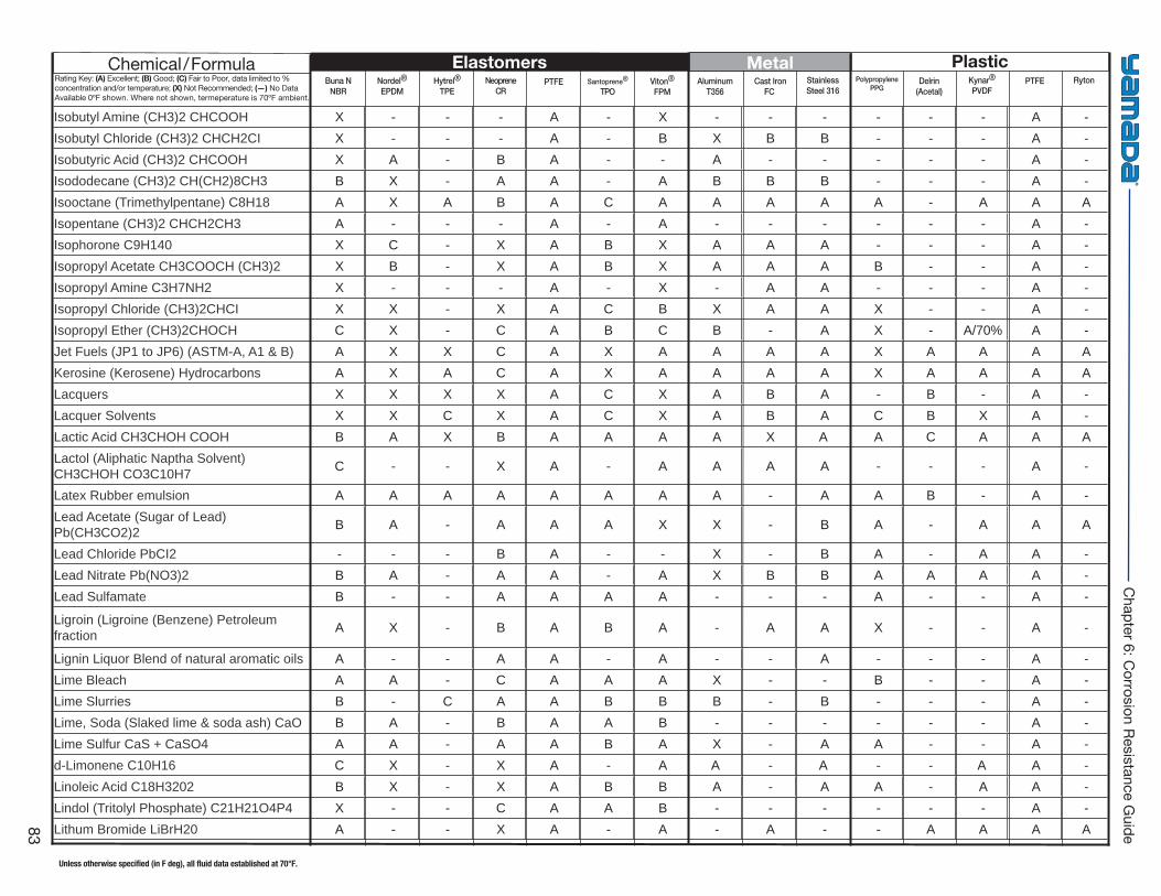
Buna NNBR
Hytrel®
TPE PTFE Viton®
FPM Cast Iron
FC Delrin
(Acetal)PTFENordel®
EPDMNeoprene
CRSantoprene®
TPOAluminum
T356StainlessSteel 316
PolypropylenePPG
Kynar®
PVDFRyton
Elastomers Metal PlasticChemical/FormulaRating Key: (A) Excellent; (B) Good; (C) Fair to Poor, data limited to % concentration and/or temperature; (X) Not Recommended; (—) No Data Available 0ºF shown. Where not shown, termeperature is 70ºF ambient.
Unless otherwise specified (in F deg), all fluid data established at 70°F.
83
Chapter 6: C
orrosion Resistance Guide
Isobutyl Amine (CH3)2 CHCOOH X - - - A - X - - - - - - A - Isobutyl Chloride (CH3)2 CHCH2CI X - - - A - B X B B - - - A - Isobutyric Acid (CH3)2 CHCOOH X A - B A - - A - - - - - A - Isododecane (CH3)2 CH(CH2)8CH3 B X - A A - A B B B - - - A - Isooctane (Trimethylpentane) C8H18 A X A B A C A A A A A - A A A Isopentane (CH3)2 CHCH2CH3 A - - - A - A - - - - - - A - Isophorone C9H140 X C - X A B X A A A - - - A - Isopropyl Acetate CH3COOCH (CH3)2 X B - X A B X A A A B - - A - Isopropyl Amine C3H7NH2 X - - - A - X - A A - - - A - Isopropyl Chloride (CH3)2CHCI X X - X A C B X A A X - - A - Isopropyl Ether (CH3)2CHOCH C X - C A B C B - A X - A/70% A - Jet Fuels (JP1 to JP6) (ASTM-A, A1 & B) A X X C A X A A A A X A A A A Kerosine (Kerosene) Hydrocarbons A X A C A X A A A A X A A A A Lacquers X X X X A C X A B A - B - A - Lacquer Solvents X X C X A C X A B A C B X A - Lactic Acid CH3CHOH COOH B A X B A A A A X A A C A A A Lactol (Aliphatic Naptha Solvent) CH3CHOH CO3C10H7 C - - X A - A A A A - - - A -
Latex Rubber emulsion A A A A A A A A - A A B - A - Lead Acetate (Sugar of Lead) Pb(CH3CO2)2 B A - A A A X X - B A - A A A
Lead Chloride PbCI2 - - - B A - - X - B A - A A - Lead Nitrate Pb(NO3)2 B A - A A - A X B B A A A A - Lead Sulfamate B - - A A A A - - - A - - A -
Ligroin (Ligroine (Benzene) Petroleum fraction A X - B A B A - A A X - - A -
Lignin Liquor Blend of natural aromatic oils A - - A A - A - - A - - - A - Lime Bleach A A - C A A A X - - B - - A - Lime Slurries B - C A A B B B - B - - - A - Lime, Soda (Slaked lime & soda ash) CaO B A - B A A B - - - - - - A - Lime Sulfur CaS + CaSO4 A A - A A B A X - A A - - A - d-Limonene C10H16 C X - X A - A A - A - - A A - Linoleic Acid C18H3202 B X - X A B B A - A A - A A - Lindol (Tritolyl Phosphate) C21H21O4P4 X - - C A A B - - - - - - A - Lithum Bromide LiBrH20 A - - X A - A - A - - A A A A
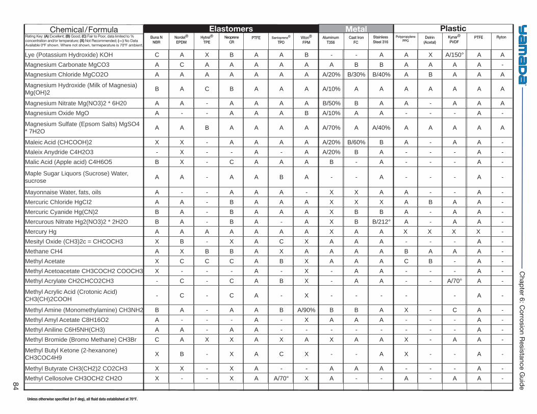
Buna NNBR
Hytrel®
TPE PTFE Viton®
FPM Cast Iron
FC Delrin
(Acetal)PTFENordel®
EPDMNeoprene
CRSantoprene®
TPOAluminum
T356StainlessSteel 316
PolypropylenePPG
Kynar®
PVDFRyton
Elastomers Metal PlasticChemical/FormulaRating Key: (A) Excellent; (B) Good; (C) Fair to Poor, data limited to % concentration and/or temperature; (X) Not Recommended; (—) No Data Available 0ºF shown. Where not shown, termeperature is 70ºF ambient.
Unless otherwise specified (in F deg), all fluid data established at 70°F.
84
Chapter 6: C
orrosion Resistance Guide
Lye (Potassium Hydroxide) KOH C A X B A A B - - A A X A/150° A A Magnesium Carbonate MgCO3 A C A A A A A A B B A A A A - Magnesium Chloride MgCO2O A A A A A A A A/20% B/30% B/40% A B A A A
Magnesium Hydroxide (Milk of Magnesia) Mg(OH)2 B A C B A A A A/10% A A A A A A A
Magnesium Nitrate Mg(NO3)2 * 6H20 A A - A A A A B/50% B A A - A A A Magnesium Oxide MgO A - - A A A B A/10% A A - - - A -
Magnesium Sulfate (Epsom Salts) MgSO4 * 7H2O A A B A A A A A/70% A A/40% A A A A A
Maleic Acid (CHCOOH)2 X X - A A A A A/20% B/60% B A - A A - Maleix Anydride C4H2O3 - X - - A - A A/20% B A - - - A - Malic Acid (Apple acid) C4H6O5 B X - C A A A B - A - - - A -
Maple Sugar Liquors (Sucrose) Water, sucrose A A - A A B A - - A - - - A -
Mayonnaise Water, fats, oils A - - A A A - X X A A - - A - Mercuric Chloride HgCI2 A A - B A A A X X X A B A A - Mercuric Cyanide Hg(CN)2 B A - B A A A X B B A - A A - Mercurous Nitrate Hg2(NO3)2 * 2H2O B A - B A - A X B B/212° A - A A - Mercury Hg A A A A A A A X A A X X X X - Mesityl Oxide (CH3)2c = CHCOCH3 X B - X A C X A A A - - - A - Methane CH4 A X B B A X A A A A B A A A - Methyl Acetate X C C C A B X A A A C B - A - Methyl Acetoacetate CH3COCH2 COOCH3 X - - - A - X - A A - - - A - Methyl Acrylate CH2CHCO2CH3 - C - C A B X - A A - - A/70° A -
Methyl Acrylic Acid (Crotonic Acid) CH3(CH)2COOH - C - C A - X - - - - - A -
Methyl Amine (Monomethylamine) CH3NH2 B A - A A B A/90% B B A X - C A - Methyl Amyl Acetate C8H16O2 A - - - A - X A A A - - - A - Methyl Aniline C6H5NH(CH3) A A - A A - - - - - - - - A - Methyl Bromide (Bromo Methane) CH3Br C A X X A X A X A A X - A A -
Methyl Butyl Ketone (2-hexanone) CH3COC4H9 X B - X A C X - - A X - - A -
Methyl Butyrate CH3(CH2)2 CO2CH3 X X - X A - - A A A - - - A - Methyl Cellosolve CH3OCH2 CH2O X - - X A A/70° X A - - A - A A -
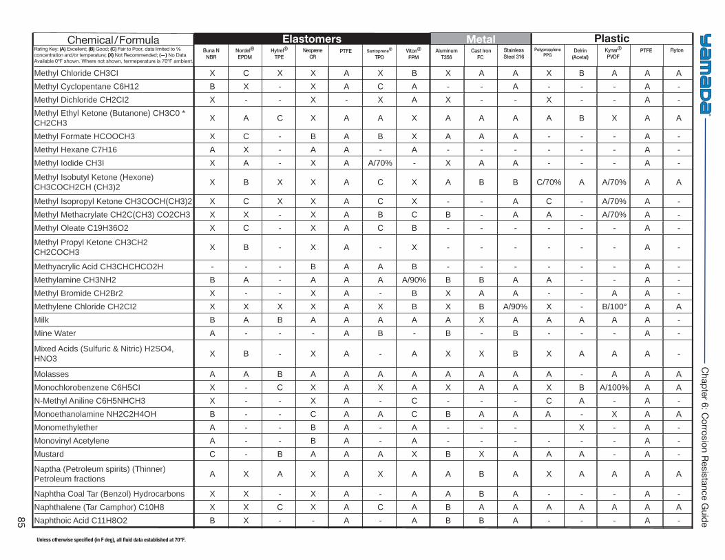
Buna NNBR
Hytrel®
TPE PTFE Viton®
FPM Cast Iron
FC Delrin
(Acetal)PTFENordel®
EPDMNeoprene
CRSantoprene®
TPOAluminum
T356StainlessSteel 316
PolypropylenePPG
Kynar®
PVDFRyton
Elastomers Metal PlasticChemical/FormulaRating Key: (A) Excellent; (B) Good; (C) Fair to Poor, data limited to % concentration and/or temperature; (X) Not Recommended; (—) No Data Available 0ºF shown. Where not shown, termeperature is 70ºF ambient.
Unless otherwise specified (in F deg), all fluid data established at 70°F.
85
Chapter 6: C
orrosion Resistance Guide
Methyl Chloride CH3CI X C X X A X B X A A X B A A A Methyl Cyclopentane C6H12 B X - X A C A - - A - - - A - Methyl Dichloride CH2CI2 X - - X - X A X - - X - - A - Methyl Ethyl Ketone (Butanone) CH3C0 * CH2CH3 X A C X A A X A A A A B X A A
Methyl Formate HCOOCH3 X C - B A B X A A A - - - A - Methyl Hexane C7H16 A X - A A - A - - - - - - A - Methyl Iodide CH3I X A - X A A/70% - X A A - - - A -
Methyl Isobutyl Ketone (Hexone) CH3COCH2CH (CH3)2 X B X X A C X A B B C/70% A A/70% A A
Methyl Isopropyl Ketone CH3COCH(CH3)2 X C X X A C X - - A C - A/70% A - Methyl Methacrylate CH2C(CH3) CO2CH3 X X - X A B C B - A A - A/70% A - Methyl Oleate C19H36O2 X C - X A C B - - - - - - A -
Methyl Propyl Ketone CH3CH2 CH2COCH3 X B - X A - X - - - - - - A -
Methyacrylic Acid CH3CHCHCO2H - - - B A A B - - - - - - A - Methylamine CH3NH2 B A - A A A A/90% B B A A - - A - Methyl Bromide CH2Br2 X - - X A - B X A A - - A A - Methylene Chloride CH2CI2 X X X X A X B X B A/90% X - B/100° A A Milk B A B A A A A A X A A A A A - Mine Water A - - - A B - B - B - - - A -
Mixed Acids (Sulfuric & Nitric) H2SO4, HNO3 X B - X A - A X X B X A A A -
Molasses A A B A A A A A A A A - A A A Monochlorobenzene C6H5CI X - C X A X A X A A X B A/100% A A N-Methyl Aniline C6H5NHCH3 X - - X A - C - - - C A - A - Monoethanolamine NH2C2H4OH B - - C A A C B A A A - X A A Monomethylether A - - B A - A - - - X - A - Monovinyl Acetylene A - - B A - A - - - - - - A - Mustard C - B A A A X B X A A A - A -
Naptha (Petroleum spirits) (Thinner) Petroleum fractions A X A X A X A A B A X A A A A
Naphtha Coal Tar (Benzol) Hydrocarbons X X - X A - A A B A - - - A - Naphthalene (Tar Camphor) C10H8 X X C X A C A B A A A A A A A Naphthoic Acid C11H8O2 B X - - A - A B B A - - - A -
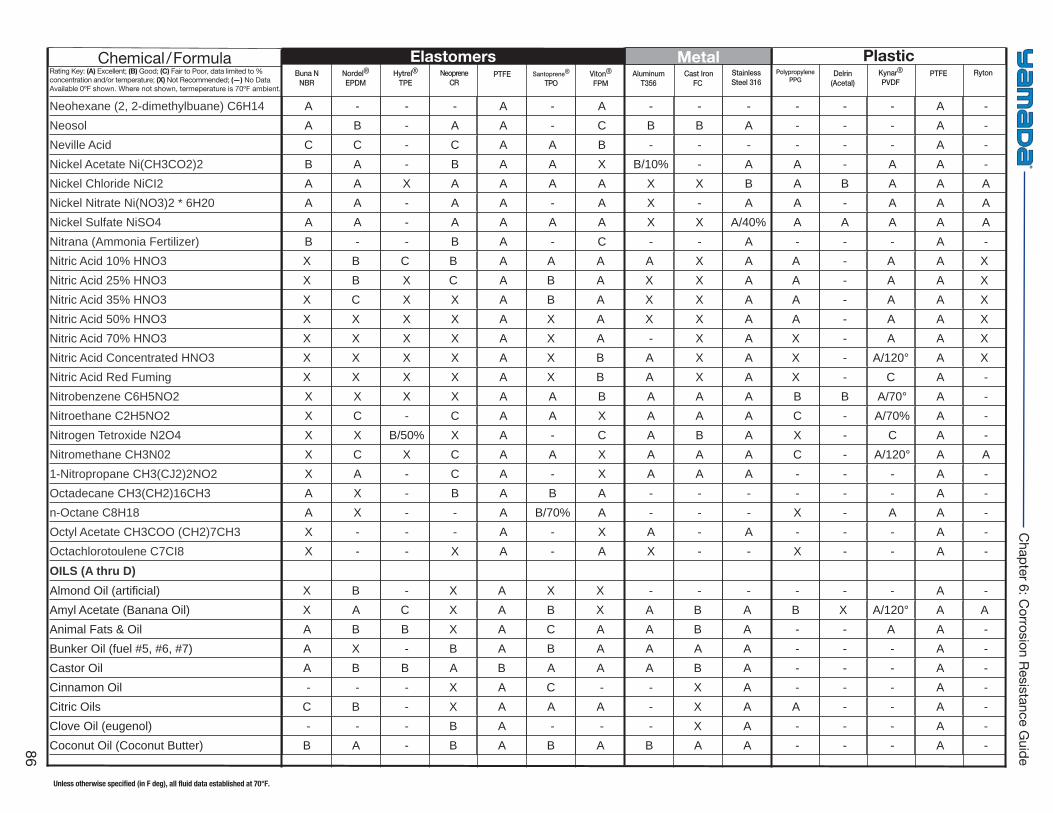
Buna NNBR
Hytrel®
TPE PTFE Viton®
FPM Cast Iron
FC Delrin
(Acetal)PTFENordel®
EPDMNeoprene
CRSantoprene®
TPOAluminum
T356StainlessSteel 316
PolypropylenePPG
Kynar®
PVDFRyton
Elastomers Metal PlasticChemical/FormulaRating Key: (A) Excellent; (B) Good; (C) Fair to Poor, data limited to % concentration and/or temperature; (X) Not Recommended; (—) No Data Available 0ºF shown. Where not shown, termeperature is 70ºF ambient.
Unless otherwise specified (in F deg), all fluid data established at 70°F.
86
Chapter 6: C
orrosion Resistance Guide
Neohexane (2, 2-dimethylbuane) C6H14 A - - - A - A - - - - - - A - Neosol A B - A A - C B B A - - - A - Neville Acid C C - C A A B - - - - - - A - Nickel Acetate Ni(CH3CO2)2 B A - B A A X B/10% - A A - A A - Nickel Chloride NiCI2 A A X A A A A X X B A B A A A Nickel Nitrate Ni(NO3)2 * 6H20 A A - A A - A X - A A - A A A Nickel Sulfate NiSO4 A A - A A A A X X A/40% A A A A A Nitrana (Ammonia Fertilizer) B - - B A - C - - A - - - A - Nitric Acid 10% HNO3 X B C B A A A A X A A - A A XNitric Acid 25% HNO3 X B X C A B A X X A A - A A XNitric Acid 35% HNO3 X C X X A B A X X A A - A A XNitric Acid 50% HNO3 X X X X A X A X X A A - A A XNitric Acid 70% HNO3 X X X X A X A - X A X - A A XNitric Acid Concentrated HNO3 X X X X A X B A X A X - A/120° A XNitric Acid Red Fuming X X X X A X B A X A X - C A - Nitrobenzene C6H5NO2 X X X X A A B A A A B B A/70° A - Nitroethane C2H5NO2 X C - C A A X A A A C - A/70% A - Nitrogen Tetroxide N2O4 X X B/50% X A - C A B A X - C A - Nitromethane CH3N02 X C X C A A X A A A C - A/120° A A 1-Nitropropane CH3(CJ2)2NO2 X A - C A - X A A A - - - A - Octadecane CH3(CH2)16CH3 A X - B A B A - - - - - - A - n-Octane C8H18 A X - - A B/70% A - - - X - A A - Octyl Acetate CH3COO (CH2)7CH3 X - - - A - X A - A - - - A - Octachlorotoulene C7CI8 X - - X A - A X - - X - - A - OILS (A thru D)Almond Oil (artifi cial) X B - X A X X - - - - - - A - Amyl Acetate (Banana Oil) X A C X A B X A B A B X A/120° A AAnimal Fats & Oil A B B X A C A A B A - - A A - Bunker Oil (fuel #5, #6, #7) A X - B A B A A A A - - - A - Castor Oil A B B A B A A A B A - - - A - Cinnamon Oil - - - X A C - - X A - - - A - Citric Oils C B - X A A A - X A A - - A - Clove Oil (eugenol) - - - B A - - - X A - - - A - Coconut Oil (Coconut Butter) B A - B A B A B A A - - - A -
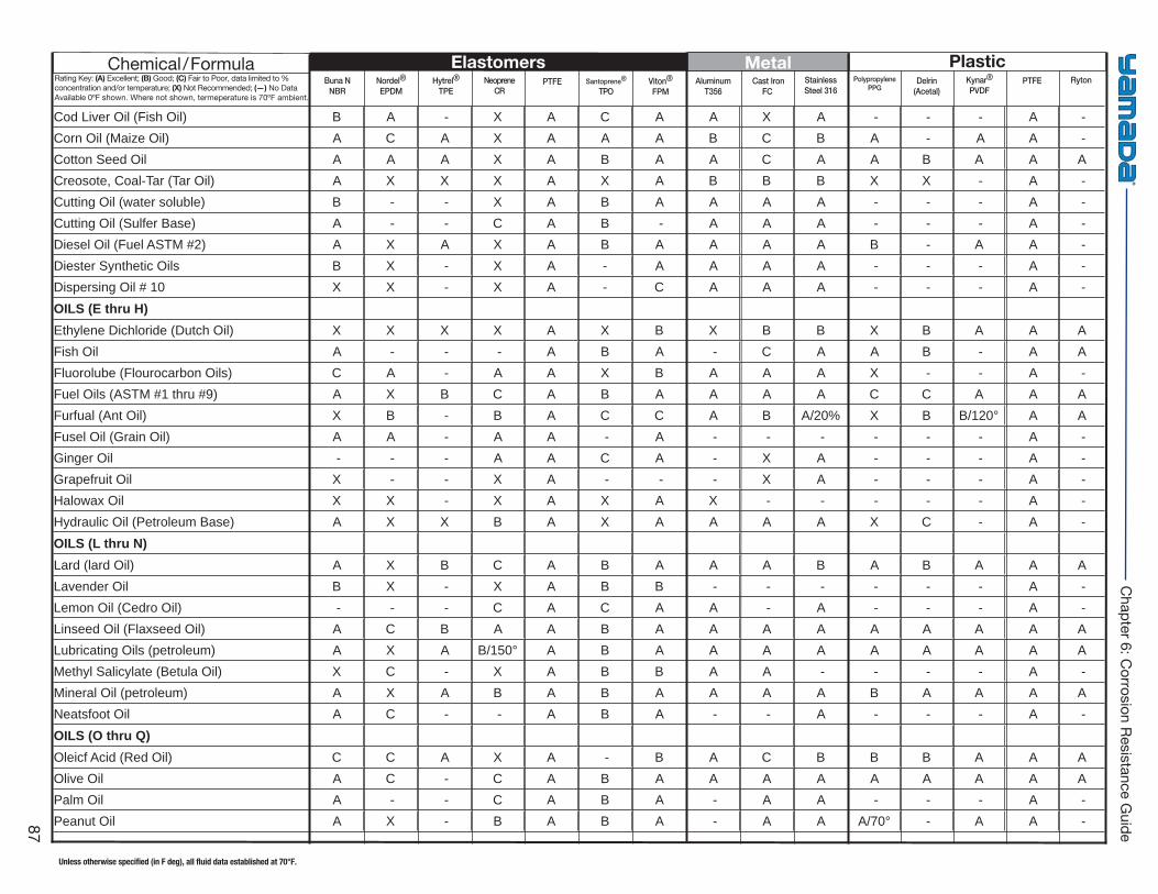
Buna NNBR
Hytrel®
TPE PTFE Viton®
FPM Cast Iron
FC Delrin
(Acetal)PTFENordel®
EPDMNeoprene
CRSantoprene®
TPOAluminum
T356StainlessSteel 316
PolypropylenePPG
Kynar®
PVDFRyton
Elastomers Metal PlasticChemical/FormulaRating Key: (A) Excellent; (B) Good; (C) Fair to Poor, data limited to % concentration and/or temperature; (X) Not Recommended; (—) No Data Available 0ºF shown. Where not shown, termeperature is 70ºF ambient.
Unless otherwise specified (in F deg), all fluid data established at 70°F.
87
Chapter 6: C
orrosion Resistance Guide
Cod Liver Oil (Fish Oil) B A - X A C A A X A - - - A - Corn Oil (Maize Oil) A C A X A A A B C B A - A A - Cotton Seed Oil A A A X A B A A C A A B A A ACreosote, Coal-Tar (Tar Oil) A X X X A X A B B B X X - A - Cutting Oil (water soluble) B - - X A B A A A A - - - A - Cutting Oil (Sulfer Base) A - - C A B - A A A - - - A - Diesel Oil (Fuel ASTM #2) A X A X A B A A A A B - A A - Diester Synthetic Oils B X - X A - A A A A - - - A - Dispersing Oil # 10 X X - X A - C A A A - - - A - OILS (E thru H)Ethylene Dichloride (Dutch Oil) X X X X A X B X B B X B A A AFish Oil A - - - A B A - C A A B - A AFluorolube (Flourocarbon Oils) C A - A A X B A A A X - - A - Fuel Oils (ASTM #1 thru #9) A X B C A B A A A A C C A A AFurfual (Ant Oil) X B - B A C C A B A/20% X B B/120° A AFusel Oil (Grain Oil) A A - A A - A - - - - - - A - Ginger Oil - - - A A C A - X A - - - A - Grapefruit Oil X - - X A - - - X A - - - A - Halowax Oil X X - X A X A X - - - - - A - Hydraulic Oil (Petroleum Base) A X X B A X A A A A X C - A - OILS (L thru N)Lard (lard Oil) A X B C A B A A A B A B A A ALavender Oil B X - X A B B - - - - - - A -Lemon Oil (Cedro Oil) - - - C A C A A - A - - - A -Linseed Oil (Flaxseed Oil) A C B A A B A A A A A A A A ALubricating Oils (petroleum) A X A B/150° A B A A A A A A A A AMethyl Salicylate (Betula Oil) X C - X A B B A A - - - - A -Mineral Oil (petroleum) A X A B A B A A A A B A A A ANeatsfoot Oil A C - - A B A - - A - - - A -OILS (O thru Q)Oleicf Acid (Red Oil) C C A X A - B A C B B B A A AOlive Oil A C - C A B A A A A A A A A APalm Oil A - - C A B A - A A - - - A -Peanut Oil A X - B A B A - A A A/70° - A A -
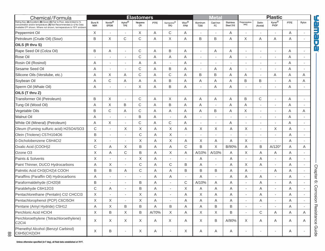
Buna NNBR
Hytrel®
TPE PTFE Viton®
FPM Cast Iron
FC Delrin
(Acetal)PTFENordel®
EPDMNeoprene
CRSantoprene®
TPOAluminum
T356StainlessSteel 316
PolypropylenePPG
Kynar®
PVDFRyton
Elastomers Metal PlasticChemical/FormulaRating Key: (A) Excellent; (B) Good; (C) Fair to Poor, data limited to % concentration and/or temperature; (X) Not Recommended; (—) No Data Available 0ºF shown. Where not shown, termeperature is 70ºF ambient.
Unless otherwise specified (in F deg), all fluid data established at 70°F.
88
Chapter 6: C
orrosion Resistance Guide
Peppermint Oil X - - X A C A - - A - - - A -Petroleum (Crude Oil) (Sour) B X C C A X A B B A X A A A -OILS (R thru S)Rape Seed Oil (Colza Oil) B A - C A B A - A A - - - A -Rose Oil - - - C A A A - - A - - - A -Rosin Oil (Rosinol) A - - A A - A - - - - - - A -Sesame Seed Oil A - - C A B A - A A - - - A -Silicone Oils (Versilube, etc.) A X A C A C A B B A A - A A ASoybean Oil A C A A A B A A A A B B - A ASperm Oil (Whale Oil) A - - X A B A - A A - - - A -OILS (T thru Z)Transformer Oil (Petroleum) B X - C A X A A A A B C - A -Tung Oil (Wood Oil) A X B C A B A A - A A - - A - Vegetable Oils B C A C A A A A B A X - - A AWalnut Oil A - - B A - A - - - - - - A -White Oil (Mineral) (Petroleum) A X - C A C A - - A - - - A -Oleum (Fuming sulfuric acid) H2SO4/SO3 C - X X A X A X X A X - X A - Olein (Triolene) C57H104O6 B - - C A X - - - - - - - A - 0-Dicholobenzene C6H4CI2 X - - X A X A X A A X - - A - Oxalic Acid (COOH)2 C A X B A A C B X B/90% A B A/120° A A Ozone O3 X A C B A X A A/10% A/10% A X A A A - Paints & Solvents X - - X A - - A - A - A - A - Paint Thinner, DUCO Hydrocarbons A X - C A C B A - A X A - A - Palmitic Acid CH3(CH2)4 COOH B B A C A A B B B A A - A A - Paraffi ns (Paraffi n Oil) Hydrocarbons A - - - A A - A - A A A - A - Paraformaldehyde (CH20)8 B - - B A - C A/10% A A - A - A - Paraldehyde C6H12O3 C A - B A - X A A A - A - A - Pentachlorethane (Pentalin) CI2 CHCCI3 X - - X A - A X A A - A - A - Pentachlorophenol (PCP) C6CI5OH X X - X A - A A A A - A - A - Pentane (Amyl Hydride) C5H12 A X B B A B A A B B - - - A - Perchloric Acid HCIO4 X B X B A/70% X A X X B - C A A A Perchloroethylene (Tetrachloroethylene) C2CI4 X X X X A X A X B A/90% X A A A A
Phenethyl Alcohol (Benzyl Carbinol) C6H5(CH2)OH X B - X A - X A A A - - - A -
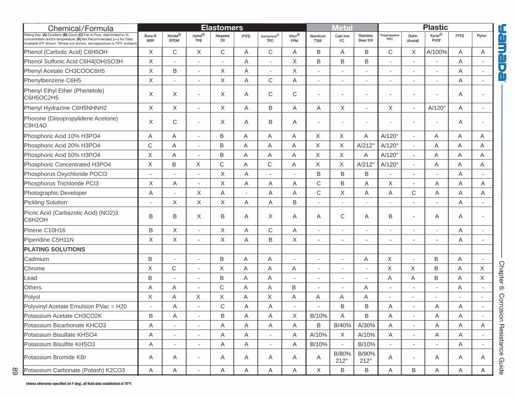
Buna NNBR
Hytrel®
TPE PTFE Viton®
FPM Cast Iron
FC Delrin
(Acetal)PTFENordel®
EPDMNeoprene
CRSantoprene®
TPOAluminum
T356StainlessSteel 316
PolypropylenePPG
Kynar®
PVDFRyton
Elastomers Metal PlasticChemical/FormulaRating Key: (A) Excellent; (B) Good; (C) Fair to Poor, data limited to % concentration and/or temperature; (X) Not Recommended; (—) No Data Available 0ºF shown. Where not shown, termeperature is 70ºF ambient.
Unless otherwise specified (in F deg), all fluid data established at 70°F.
89
Chapter 6: C
orrosion Resistance Guide
Phenol (Carbolic Acid) C6H5OH X C X C A C A B A B C X A/100% A A Phenol Sulfonic Acid C6H4(OH)SO3H X - - - A - X B B B - - - A - Phenyl Acetate CH3COOC6H5 X B - X A - X - - - - - - A - Phenylbenzene C6H5 X - - X A C A - - - - - - A -
Phenyl Ethyl Ether (Phenetole) C6H5OC2H5 X X - X A C C - - - - - - A -
Phenyl Hydrazine C6H5NHNH2 X X - X A B A A X - X - A/120° A -
Phorone (Diisopropylidene Acetone) C9H14O X C - X A B A - - - - - - A -
Phosphoric Acid 10% H3PO4 A A - B A A A X X A A/120° - A A APhosphoric Acid 20% H3PO4 C A - B A A A X X A/212° A/120° - A A APhosphoric Acid 50% H3PO4 X A - B A A A X X A A/120° - A A APhosphoric Concentrated H3PO4 X B X C A C A X X A/212° A/120° - A A APhosphorus Oxychloride POCI3 - - - X A - - B B B - - - A - Phosphorus Trichloride PCI3 X A - X A A A C B A X - A A A Photographic Developer A - X A - A A C X A A C A A A Pickling Solution - X X X A A B - - - - - - A -
Picric Acid (Carbazotic Acid) (NO2)3 C6H2OH B B X B A X A A C A B - A A -
Pinene C10H16 B X - X A C A - - - - - - A - Piperidine C5H11N X X - X A B X - - - - - - A - PLATING SOLUTIONSCadmium B - - B A A - - - A X - B A -Chrome X C - X A A A - - - X X B A XLead B - - B A A - - - - A A B A XOthers A A - C A A B - - A - - - A -Polyol X A X X A X A A A A - - - - -Polyvinyl Acetate Emulsion PVac = H20 - A - C A A - - B B A - A A - Potassium Acetate CH3CO2K B A - B A A X B/10% A B A - A A - Potassium Bicarbonate KHCO3 A - - A A A A B B/40% A/30% A - A A A Potassium Bisulfate KHSO4 A - - A A - A A/10% X A/10% A - A A - Potassium Bisulfi te KHSO3 A - - A A - A B/10% - B/10% - - - A -
Potassium Bromide KBr A A - A A A A A B/80% 212°
B/90% 212° A - A A A
Potassium Carbonate (Potash) K2CO3 A A - A A A A X B B A B A A A
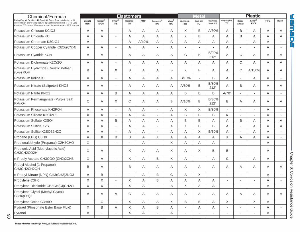
Buna NNBR
Hytrel®
TPE PTFE Viton®
FPM Cast Iron
FC Delrin
(Acetal)PTFENordel®
EPDMNeoprene
CRSantoprene®
TPOAluminum
T356StainlessSteel 316
PolypropylenePPG
Kynar®
PVDFRyton
Elastomers Metal PlasticChemical/FormulaRating Key: (A) Excellent; (B) Good; (C) Fair to Poor, data limited to % concentration and/or temperature; (X) Not Recommended; (—) No Data Available 0ºF shown. Where not shown, termeperature is 70ºF ambient.
Unless otherwise specified (in F deg), all fluid data established at 70°F.
90
Chapter 6: C
orrosion Resistance Guide
Potassium Chlorate KCIO3 A A - A A A A X B A/60% A B A A A Potassium Chloride KCI A A - A A A A X B A A B A A A Potassium Chromate K2CrO4 A - - A A/40% A A A A A A - A A - Potassium Copper Cyanide K3[Cu(CN)4] A A - A A - A - - - A - - A -
Potassium Cyanide KCN A A - A A A A C B B/90% 212° A C A A A
Potassium Dichromate K2Cr2O A A - A A A A A A A A C A A A
Potassium Hydroxide (Caustic Potash) (Lye) KOH B A X B A A B X B A A C A/150% A A
Potassium Iodide KI A A - A A A A B/10% - B A - A A -
Potassium Nitrate (Saltpeter) KNO3 A A - A A A A A/80% B B/80% 212° A B A A A
Potassium Nitrite KNO2 A A B A A A A B B B A/70° - - A -
Potassium Permanganate (Purple Salt) KMnO4 C A X C A A B A/10% B B/30%
212° B A A A A
Potassium Phosphate KH2PO4 A A - A A - A X X B/30% - - - A - Potassium Silicate K2Sii2O5 A A - A A - A B B B A - - A - Potassium Sulfate K2SO4 A A B A A A A B B A A B A A A Potassium Sulfi de K2S A A - A A - A X B B A - A A A Potassium Sulfi te K2SO32H2O A A - A A - A A X B/50% A - A A - Propane (LPG) C3H8 A X B B A X A A A A X A A A - Propionaldehyde (Propanal) C2H5CHO X - - - A - X A A A - - - A -
Propionic Acid (Methylacetic Acid) CH3CH2CO2H X A - X A A X A X B B - - A -
n-Proply Acetate CH3COO (CH2)2CH3 X A - X A B X A - A C - A A -
Propyl Alcohol (1-Propanol) CH3CH2CH2OH B A - B A A A A A A A A A A A
n-Propyl Nitrate (NPN) CH3(CH2)2NO3 A B - - A B C A X - - - - A - Propylene C3H6 X X - X A B A A A A - - - A - Propylene Dichloride CH3CH(CI)CH2CI X X - X A - B X A A - - - A -
Propylene Glycol (Methyl Glycol) C3H6(OH)2 A A A C A A A A A A A A A A A
Propylene Oxide C3H6O - C - X A A X B B A X - X A - Pydraul (Phosphate Ester Base Fluid) X B A X A B A - A A - - - A - Pyranol A - - X A - A - - - - - - A -
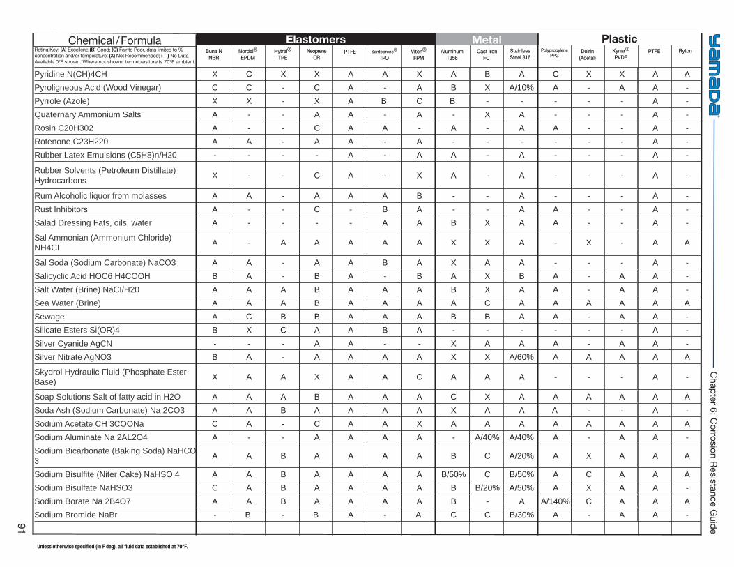
Buna NNBR
Hytrel®
TPE PTFE Viton®
FPM Cast Iron
FC Delrin
(Acetal)PTFENordel®
EPDMNeoprene
CRSantoprene®
TPOAluminum
T356StainlessSteel 316
PolypropylenePPG
Kynar®
PVDFRyton
Elastomers Metal PlasticChemical/FormulaRating Key: (A) Excellent; (B) Good; (C) Fair to Poor, data limited to % concentration and/or temperature; (X) Not Recommended; (—) No Data Available 0ºF shown. Where not shown, termeperature is 70ºF ambient.
Unless otherwise specified (in F deg), all fluid data established at 70°F.
91
Chapter 6: C
orrosion Resistance Guide
Pyridine N(CH)4CH X C X X A A X A B A C X X A A Pyroligneous Acid (Wood Vinegar) C C - C A - A B X A/10% A - A A - Pyrrole (Azole) X X - X A B C B - - - - - A - Quaternary Ammonium Salts A - - A A - A - X A - - - A - Rosin C20H302 A - - C A A - A - A A - - A - Rotenone C23H220 A A - A A - A - - - - - - A - Rubber Latex Emulsions (C5H8)n/H20 - - - - A - A A - A - - - A -
Rubber Solvents (Petroleum Distillate) Hydrocarbons X - - C A - X A - A - - - A -
Rum Alcoholic liquor from molasses A A - A A A B - - A - - - A - Rust Inhibitors A - - C - B A - - A A - - A - Salad Dressing Fats, oils, water A - - - - A A B X A A - - A -
Sal Ammonian (Ammonium Chloride) NH4CI A - A A A A A X X A - X - A A
Sal Soda (Sodium Carbonate) NaCO3 A A - A A B A X A A - - - A - Salicyclic Acid HOC6 H4COOH B A - B A - B A X B A - A A - Salt Water (Brine) NaCI/H20 A A A B A A A B X A A - A A - Sea Water (Brine) A A A B A A A A C A A A A A A Sewage A C B B A A A B B A A - A A - Silicate Esters Si(OR)4 B X C A A B A - - - - - - A - Silver Cyanide AgCN - - - A A - - X A A A - A A - Silver Nitrate AgNO3 B A - A A A A X X A/60% A A A A A
Skydrol Hydraulic Fluid (Phosphate Ester Base) X A A X A A C A A A - - - A -
Soap Solutions Salt of fatty acid in H2O A A A B A A A C X A A A A A A Soda Ash (Sodium Carbonate) Na 2CO3 A A B A A A A X A A A - - A - Sodium Acetate CH 3COONa C A - C A A X A A A A A A A A Sodium Aluminate Na 2AL2O4 A - - A A A A - A/40% A/40% A - A A - Sodium Bicarbonate (Baking Soda) NaHCO 3 A A B A A A A B C A/20% A X A A A
Sodium Bisulfi te (Niter Cake) NaHSO 4 A A B A A A A B/50% C B/50% A C A A A Sodium Bisulfate NaHSO3 C A B A A A A B B/20% A/50% A X A A - Sodium Borate Na 2B4O7 A A B A A A A B - A A/140% C A A A Sodium Bromide NaBr - B - B A - A C C B/30% A - A A -
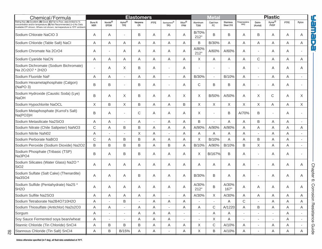
Buna NNBR
Hytrel®
TPE PTFE Viton®
FPM Cast Iron
FC Delrin
(Acetal)PTFENordel®
EPDMNeoprene
CRSantoprene®
TPOAluminum
T356StainlessSteel 316
PolypropylenePPG
Kynar®
PVDFRyton
Elastomers Metal PlasticChemical/FormulaRating Key: (A) Excellent; (B) Good; (C) Fair to Poor, data limited to % concentration and/or temperature; (X) Not Recommended; (—) No Data Available 0ºF shown. Where not shown, termeperature is 70ºF ambient.
Unless otherwise specified (in F deg), all fluid data established at 70°F.
92
Chapter 6: C
orrosion Resistance Guide
Sodium Chlorate NaCIO 3 A A - B A A A B/70% 212° B B A B A A A
Sodium Chloride (Table Salt) NaCI A A A A A A A B B/30% A A A A A A
Sodium Chromate Na 2CrO4 A - A A A A A A/80% 212° A/60% A/60% A - A A -
Sodium Cyanide NaCN A A A A A A A X A A A C A A A
Sodium Dichromate (Sodium Bichromate) Na 2Cr2O7 * 2H2O - A X B A - A - - - A - A A A
Sodium Fluoride NaF A A - A A - A B/30% - B/10% A - A A - Sodium Hexametaphosphate (Calgon) (NaPO 3) B B - B A - A C B B A - A A -
Sodium Hydroxide (Caustic Soda) (Lye) NaOH B A X B A A X X B/50% A/50% A X C A X
Sodium Hypochlorite NaOCL X B X B A A B X X X X X A A X
Sodium Metaphosphate (Kurrol’s Salt) Na(PO3)H B A - C A A A X - B A/70% B - A -
Sodium Metasilicate Na2SiO3 A A - A - A A B - A A B A A - Sodium Nitrate (Chile Saltpeter) NaNO3 C A B B A A A A/90% A/90% A/90% A A A A A Sodium Nitrite NaN02 A - - X A - A A A A A - A A - Sodium Perborate NaBO3 C A B B A A A X B/10% A A B A A - Sodium Peroxide (Sodium Dioxide) Na2O2 B B B B A B A B/10% A/90% B/10% B X A A -
Sodium Phosphate (Tribasic (TSP) Na3PO4 B A B B A A A X B/167% B A - A A -
Sodium Silicates (Water Glass) Na2O * SiO2 A A A A A A A A A A A - A A A
Sodium Sulfate (Salt Cake) (Thenardite) Na3SO4 A A A B A A A B/30% B A A - A A A
Sodium Sulfi de (Pentahydrate) Na2S * 5H2O A A A A A A A A/30%
212° B A/30% 167° A A A A A
Sodium Sulfi te Na2SO3 A A A A A - A A/30% X A/30% A A A A A Sodium Tetraborate Na2B4O710H2O A - B - A A A - - A C - A A A Sodium Thiosulfate (Antichlor) Na2s2O3 A A - A A - A A C A/1220 A B A A A Sorgum A - - A A A - - A A - - - A - Soy Sauce Fermented soya bean/wheat A - - A A A - - X A - - - A - Stannic Chloride (Tin Chloride) SnCI4 A B B B A A A X C A/10% A - A A - Stannous Chloride (Tin Salt) SnCI4 A B B/15% A A - A X B A/10% A - A A A
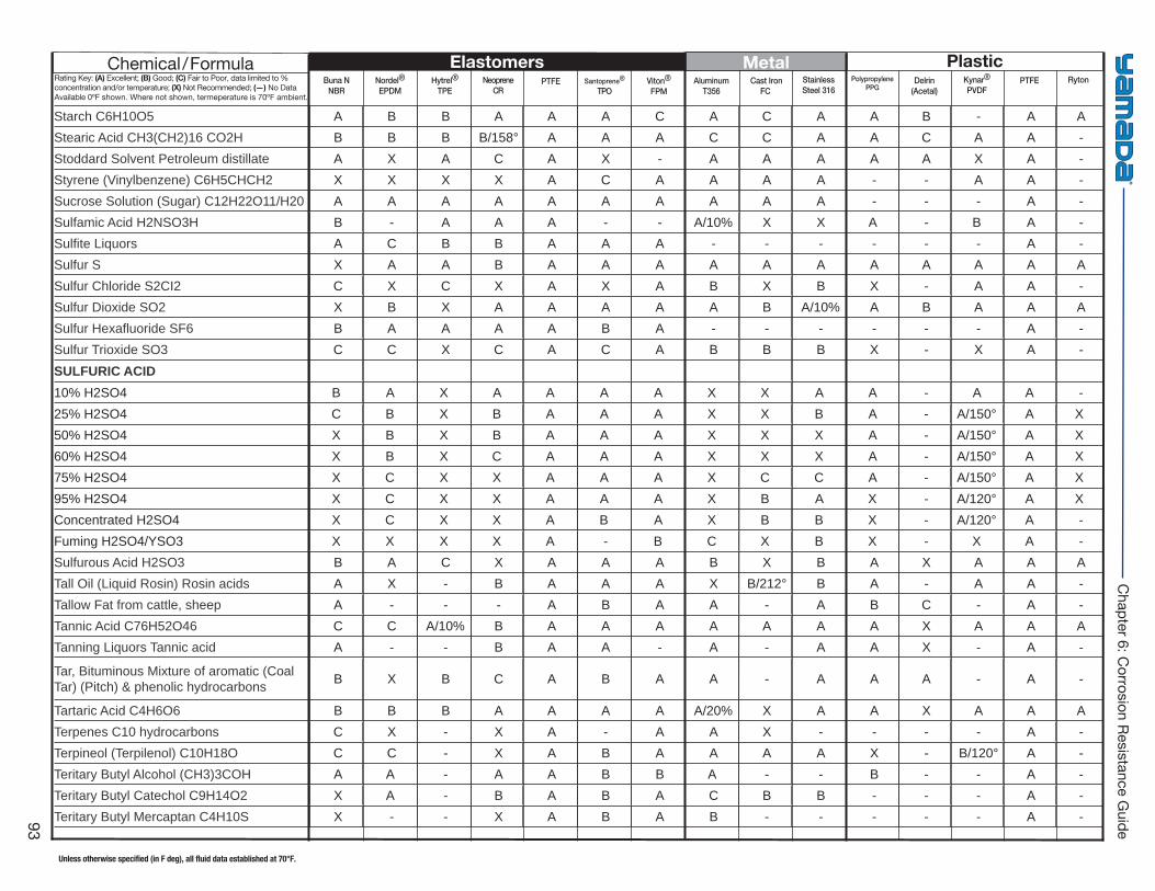
Buna NNBR
Hytrel®
TPE PTFE Viton®
FPM Cast Iron
FC Delrin
(Acetal)PTFENordel®
EPDMNeoprene
CRSantoprene®
TPOAluminum
T356StainlessSteel 316
PolypropylenePPG
Kynar®
PVDFRyton
Elastomers Metal PlasticChemical/FormulaRating Key: (A) Excellent; (B) Good; (C) Fair to Poor, data limited to % concentration and/or temperature; (X) Not Recommended; (—) No Data Available 0ºF shown. Where not shown, termeperature is 70ºF ambient.
Unless otherwise specified (in F deg), all fluid data established at 70°F.
93
Chapter 6: C
orrosion Resistance Guide
Starch C6H10O5 A B B A A A C A C A A B - A A Stearic Acid CH3(CH2)16 CO2H B B B B/158° A A A C C A A C A A - Stoddard Solvent Petroleum distillate A X A C A X - A A A A A X A - Styrene (Vinylbenzene) C6H5CHCH2 X X X X A C A A A A - - A A - Sucrose Solution (Sugar) C12H22O11/H20 A A A A A A A A A A - - - A - Sulfamic Acid H2NSO3H B - A A A - - A/10% X X A - B A - Sulfi te Liquors A C B B A A A - - - - - - A - Sulfur S X A A B A A A A A A A A A A A Sulfur Chloride S2CI2 C X C X A X A B X B X - A A - Sulfur Dioxide SO2 X B X A A A A A B A/10% A B A A A Sulfur Hexafl uoride SF6 B A A A A B A - - - - - - A - Sulfur Trioxide SO3 C C X C A C A B B B X - X A - SULFURIC ACID10% H2SO4 B A X A A A A X X A A - A A -25% H2SO4 C B X B A A A X X B A - A/150° A X50% H2SO4 X B X B A A A X X X A - A/150° A X60% H2SO4 X B X C A A A X X X A - A/150° A X75% H2SO4 X C X X A A A X C C A - A/150° A X95% H2SO4 X C X X A A A X B A X - A/120° A XConcentrated H2SO4 X C X X A B A X B B X - A/120° A -Fuming H2SO4/YSO3 X X X X A - B C X B X - X A -Sulfurous Acid H2SO3 B A C X A A A B X B A X A A A Tall Oil (Liquid Rosin) Rosin acids A X - B A A A X B/212° B A - A A - Tallow Fat from cattle, sheep A - - - A B A A - A B C - A - Tannic Acid C76H52O46 C C A/10% B A A A A A A A X A A A Tanning Liquors Tannic acid A - - B A A - A - A A X - A -
Tar, Bituminous Mixture of aromatic (Coal Tar) (Pitch) & phenolic hydrocarbons B X B C A B A A - A A A - A -
Tartaric Acid C4H6O6 B B B A A A A A/20% X A A X A A A Terpenes C10 hydrocarbons C X - X A - A A X - - - - A - Terpineol (Terpilenol) C10H18O C C - X A B A A A A X - B/120° A - Teritary Butyl Alcohol (CH3)3COH A A - A A B B A - - B - - A - Teritary Butyl Catechol C9H14O2 X A - B A B A C B B - - - A - Teritary Butyl Mercaptan C4H10S X - - X A B A B - - - - - A -
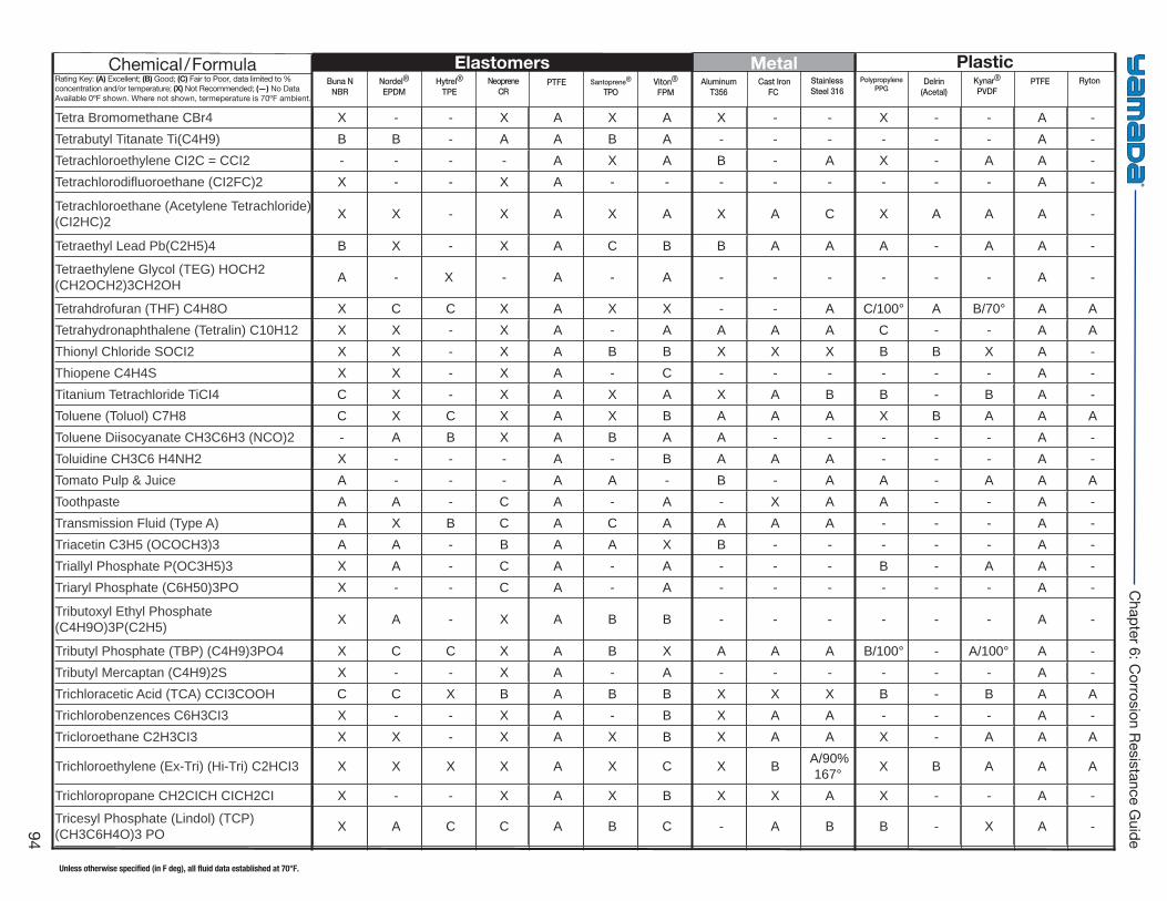
Buna NNBR
Hytrel®
TPE PTFE Viton®
FPM Cast Iron
FC Delrin
(Acetal)PTFENordel®
EPDMNeoprene
CRSantoprene®
TPOAluminum
T356StainlessSteel 316
PolypropylenePPG
Kynar®
PVDFRyton
Elastomers Metal PlasticChemical/FormulaRating Key: (A) Excellent; (B) Good; (C) Fair to Poor, data limited to % concentration and/or temperature; (X) Not Recommended; (—) No Data Available 0ºF shown. Where not shown, termeperature is 70ºF ambient.
Unless otherwise specified (in F deg), all fluid data established at 70°F.
94
Chapter 6: C
orrosion Resistance Guide
Tetra Bromomethane CBr4 X - - X A X A X - - X - - A - Tetrabutyl Titanate Ti(C4H9) B B - A A B A - - - - - - A - Tetrachloroethylene CI2C = CCI2 - - - - A X A B - A X - A A - Tetrachlorodifl uoroethane (CI2FC)2 X - - X A - - - - - - - - A -
Tetrachloroethane (Acetylene Tetrachloride) (CI2HC)2 X X - X A X A X A C X A A A -
Tetraethyl Lead Pb(C2H5)4 B X - X A C B B A A A - A A -
Tetraethylene Glycol (TEG) HOCH2 (CH2OCH2)3CH2OH A - X - A - A - - - - - - A -
Tetrahdrofuran (THF) C4H8O X C C X A X X - - A C/100° A B/70° A A Tetrahydronaphthalene (Tetralin) C10H12 X X - X A - A A A A C - - A A Thionyl Chloride SOCI2 X X - X A B B X X X B B X A - Thiopene C4H4S X X - X A - C - - - - - - A - Titanium Tetrachloride TiCI4 C X - X A X A X A B B - B A - Toluene (Toluol) C7H8 C X C X A X B A A A X B A A A Toluene Diisocyanate CH3C6H3 (NCO)2 - A B X A B A A - - - - - A - Toluidine CH3C6 H4NH2 X - - - A - B A A A - - - A - Tomato Pulp & Juice A - - - A A - B - A A - A A A Toothpaste A A - C A - A - X A A - - A - Transmission Fluid (Type A) A X B C A C A A A A - - - A - Triacetin C3H5 (OCOCH3)3 A A - B A A X B - - - - - A - Triallyl Phosphate P(OC3H5)3 X A - C A - A - - - B - A A - Triaryl Phosphate (C6H50)3PO X - - C A - A - - - - - - A -
Tributoxyl Ethyl Phosphate (C4H9O)3P(C2H5) X A - X A B B - - - - - - A -
Tributyl Phosphate (TBP) (C4H9)3PO4 X C C X A B X A A A B/100° - A/100° A - Tributyl Mercaptan (C4H9)2S X - - X A - A - - - - - - A - Trichloracetic Acid (TCA) CCI3COOH C C X B A B B X X X B - B A A Trichlorobenzences C6H3CI3 X - - X A - B X A A - - - A - Tricloroethane C2H3CI3 X X - X A X B X A A X - A A A
Trichloroethylene (Ex-Tri) (Hi-Tri) C2HCI3 X X X X A X C X B A/90% 167° X B A A A
Trichloropropane CH2CICH CICH2CI X - - X A X B X X A X - - A -
Tricesyl Phosphate (Lindol) (TCP) (CH3C6H4O)3 PO X A C C A B C - A B B - X A -
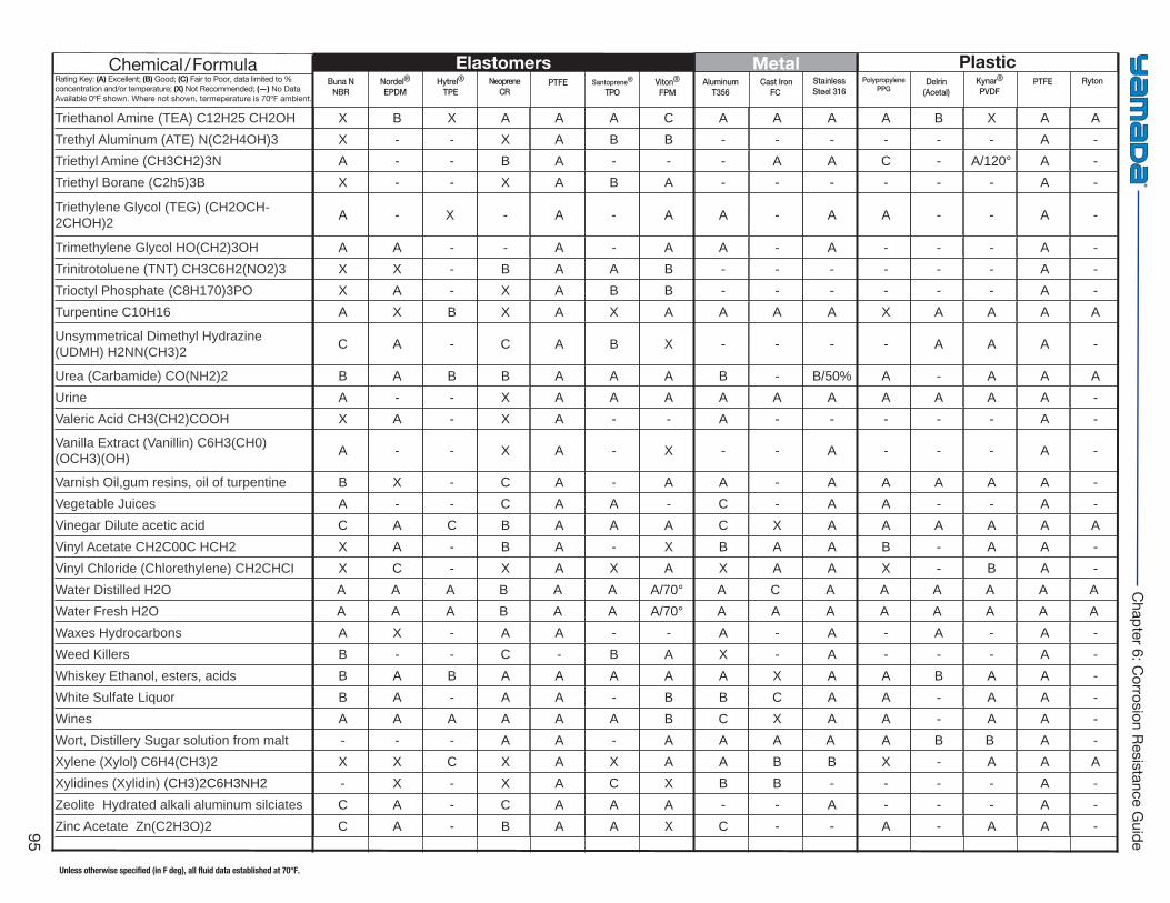
Buna NNBR
Hytrel®
TPE PTFE Viton®
FPM Cast Iron
FC Delrin
(Acetal)PTFENordel®
EPDMNeoprene
CRSantoprene®
TPOAluminum
T356StainlessSteel 316
PolypropylenePPG
Kynar®
PVDFRyton
Elastomers Metal PlasticChemical/FormulaRating Key: (A) Excellent; (B) Good; (C) Fair to Poor, data limited to % concentration and/or temperature; (X) Not Recommended; (—) No Data Available 0ºF shown. Where not shown, termeperature is 70ºF ambient.
Unless otherwise specified (in F deg), all fluid data established at 70°F.
95
Chapter 6: C
orrosion Resistance Guide
Triethanol Amine (TEA) C12H25 CH2OH X B X A A A C A A A A B X A A Trethyl Aluminum (ATE) N(C2H4OH)3 X - - X A B B - - - - - - A - Triethyl Amine (CH3CH2)3N A - - B A - - - A A C - A/120° A - Triethyl Borane (C2h5)3B X - - X A B A - - - - - - A -
Triethylene Glycol (TEG) (CH2OCH-2CHOH)2 A - X - A - A A - A A - - A -
Trimethylene Glycol HO(CH2)3OH A A - - A - A A - A - - - A - Trinitrotoluene (TNT) CH3C6H2(NO2)3 X X - B A A B - - - - - - A - Trioctyl Phosphate (C8H170)3PO X A - X A B B - - - - - - A - Turpentine C10H16 A X B X A X A A A A X A A A A
Unsymmetrical Dimethyl Hydrazine (UDMH) H2NN(CH3)2 C A - C A B X - - - - A A A -
Urea (Carbamide) CO(NH2)2 B A B B A A A B - B/50% A - A A A Urine A - - X A A A A A A A A A A - Valeric Acid CH3(CH2)COOH X A - X A - - A - - - - - A -
Vanilla Extract (Vanillin) C6H3(CH0) (OCH3)(OH) A - - X A - X - - A - - - A -
Varnish Oil,gum resins, oil of turpentine B X - C A - A A - A A A A A - Vegetable Juices A - - C A A - C - A A - - A - Vinegar Dilute acetic acid C A C B A A A C X A A A A A A Vinyl Acetate CH2C00C HCH2 X A - B A - X B A A B - A A - Vinyl Chloride (Chlorethylene) CH2CHCI X C - X A X A X A A X - B A - Water Distilled H2O A A A B A A A/70° A C A A A A A AWater Fresh H2O A A A B A A A/70° A A A A A A A AWaxes Hydrocarbons A X - A A - - A - A - A - A - Weed Killers B - - C - B A X - A - - - A - Whiskey Ethanol, esters, acids B A B A A A A A X A A B A A - White Sulfate Liquor B A - A A - B B C A A - A A - Wines A A A A A A B C X A A - A A - Wort, Distillery Sugar solution from malt - - - A A - A A A A A B B A - Xylene (Xylol) C6H4(CH3)2 X X C X A X A A B B X - A A A Xylidines (Xylidin) (CH3)2C6H3NH2 - X - X A C X B B - - - - A - Zeolite Hydrated alkali aluminum silciates C A - C A A A - - A - - - A - Zinc Acetate Zn(C2H3O)2 C A - B A A X C - - A - A A -
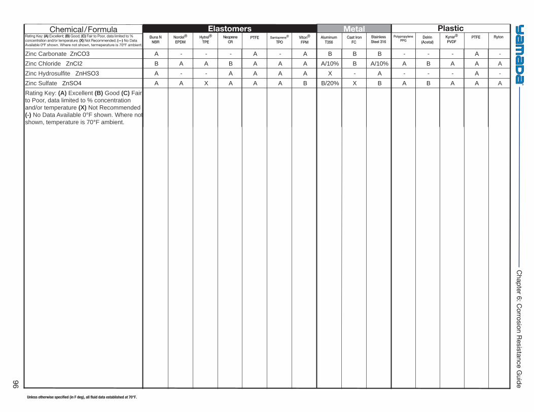
Buna NNBR
Hytrel®
TPE PTFE Viton®
FPM Cast Iron
FC Delrin
(Acetal)PTFENordel®
EPDMNeoprene
CRSantoprene®
TPOAluminum
T356StainlessSteel 316
PolypropylenePPG
Kynar®
PVDFRyton
Elastomers Metal PlasticChemical/FormulaRating Key: (A) Excellent; (B) Good; (C) Fair to Poor, data limited to % concentration and/or temperature; (X) Not Recommended; (—) No Data Available 0ºF shown. Where not shown, termeperature is 70ºF ambient.
Unless otherwise specified (in F deg), all fluid data established at 70°F.
96
Chapter 6: C
orrosion Resistance Guide
Zinc Carbonate ZnCO3 A - - - A - A B B B - - - A - Zinc Chloride ZnCI2 B A A B A A A A/10% B A/10% A B A A A Zinc Hydrosulfi te ZnHSO3 A - - A A A A X - A - - - A - Zinc Sulfate ZnSO4 A A X A A A B B/20% X B A B A A A Rating Key: (A) Excellent (B) Good (C) Fair to Poor, data limited to % concentration and/or temperature (X) Not Recommended (-) No Data Available 0°F shown. Where not shown, temperature is 70°F ambient.
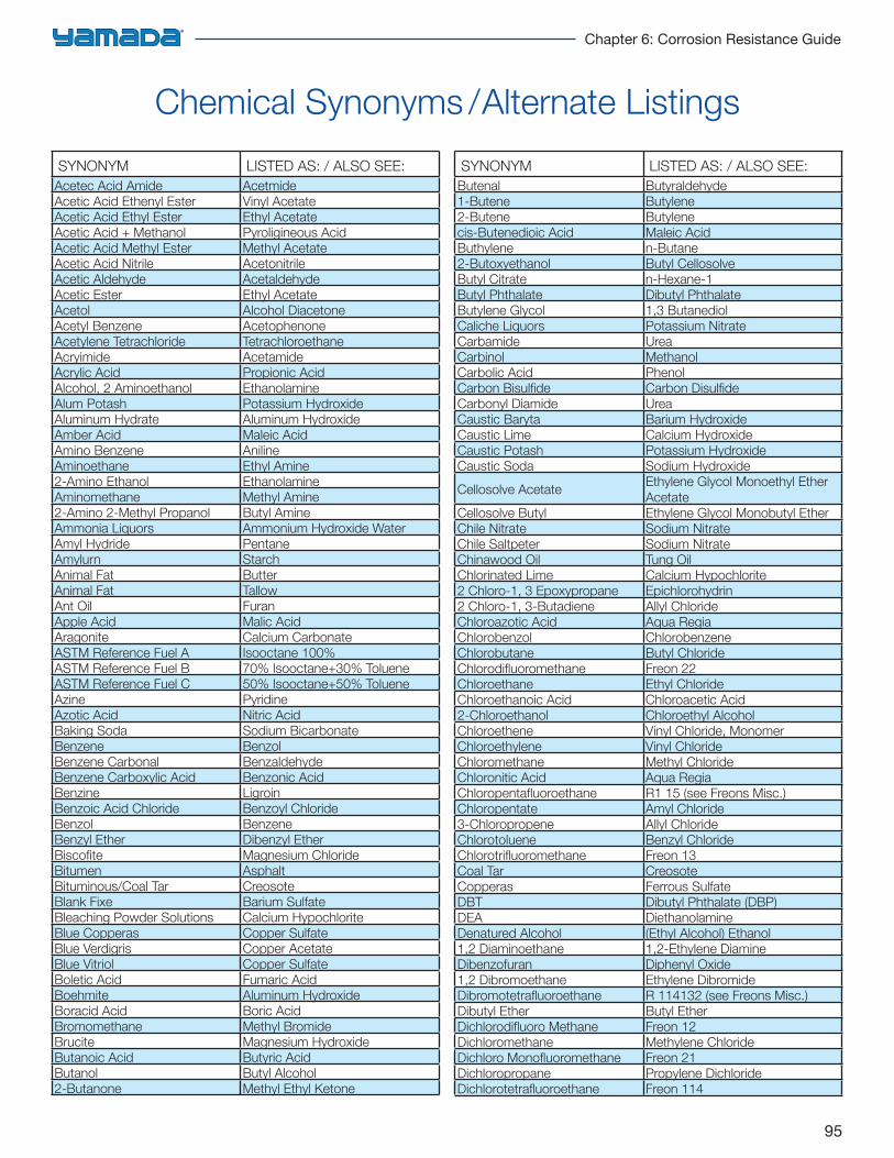
95
Chapter 6: Corrosion Resistance Guide
Chemical Synonyms /Alternate Listings
SYNONYM LISTED AS: / ALSO SEE:Acetec Acid Amide AcetmideAcetic Acid Ethenyl Ester Vinyl AcetateAcetic Acid Ethyl Ester Ethyl AcetateAcetic Acid + Methanol Pyroligineous AcidAcetic Acid Methyl Ester Methyl AcetateAcetic Acid Nitrile AcetonitrileAcetic Aldehyde AcetaldehydeAcetic Ester Ethyl AcetateAcetol Alcohol DiacetoneAcetyl Benzene AcetophenoneAcetylene Tetrachloride TetrachloroethaneAcryimide AcetamideAcrylic Acid Propionic AcidAlcohol, 2 Aminoethanol EthanolamineAlum Potash Potassium HydroxideAluminum Hydrate Aluminum HydroxideAmber Acid Maleic AcidAmino Benzene AnilineAminoethane Ethyl Amine2-Amino Ethanol EthanolamineAminomethane Methyl Amine2-Amino 2-Methyl Propanol Butyl AmineAmmonia Liquors Ammonium Hydroxide WaterAmyl Hydride PentaneAmylurn StarchAnimal Fat ButterAnimal Fat TallowAnt Oil FuranApple Acid Malic AcidAragonite Calcium CarbonateASTM Reference Fuel A Isooctane 100%ASTM Reference Fuel B 70% Isooctane+30% TolueneASTM Reference Fuel C 50% Isooctane+50% TolueneAzine PyridineAzotic Acid Nitric AcidBaking Soda Sodium BicarbonateBenzene BenzolBenzene Carbonal BenzaldehydeBenzene Carboxylic Acid Benzonic AcidBenzine LigroinBenzoic Acid Chloride Benzoyl ChlorideBenzol BenzeneBenzyl Ether Dibenzyl EtherBiscofi te Magnesium ChlorideBitumen AsphaltBituminous/Coal Tar CreosoteBlank Fixe Barium SulfateBleaching Powder Solutions Calcium HypochloriteBlue Copperas Copper SulfateBlue Verdigris Copper AcetateBlue Vitriol Copper SulfateBoletic Acid Fumaric AcidBoehmite Aluminum HydroxideBoracid Acid Boric AcidBromomethane Methyl BromideBrucite Magnesium HydroxideButanoic Acid Butyric AcidButanol Butyl Alcohol2-Butanone Methyl Ethyl Ketone
SYNONYM LISTED AS: / ALSO SEE:Butenal Butyraldehyde1-Butene Butylene2-Butene Butylenecis-Butenedioic Acid Maleic AcidButhylene n-Butane2-Butoxyethanol Butyl CellosolveButyl Citrate n-Hexane-1Butyl Phthalate Dibutyl PhthalateButylene Glycol 1,3 ButanediolCaliche Liquors Potassium NitrateCarbamide UreaCarbinol MethanolCarbolic Acid PhenolCarbon Bisulfi de Carbon Disulfi deCarbonyl Diamide UreaCaustic Baryta Barium HydroxideCaustic Lime Calcium HydroxideCaustic Potash Potassium HydroxideCaustic Soda Sodium Hydroxide
Cellosolve AcetateEthylene Glycol Monoethyl Ether Acetate
Cellosolve Butyl Ethylene Glycol Monobutyl Ether Chile Nitrate Sodium NitrateChile Saltpeter Sodium NitrateChinawood Oil Tung OilChlorinated Lime Calcium Hypochlorite2 Chloro-1, 3 Epoxypropane Epichlorohydrin2 Chloro-1, 3-Butadiene Allyl ChlorideChloroazotic Acid Aqua RegiaChlorobenzol ChlorobenzeneChlorobutane Butyl ChlorideChlorodifl uoromethane Freon 22Chloroethane Ethyl ChlorideChloroethanoic Acid Chloroacetic Acid2-Chloroethanol Chloroethyl AlcoholChloroethene Vinyl Chloride, MonomerChloroethylene Vinyl ChlorideChloromethane Methyl ChlorideChloronitic Acid Aqua RegiaChloropentafl uoroethane R1 15 (see Freons Misc.)Chloropentate Amyl Chloride3-Chloropropene Allyl ChlorideChlorotoluene Benzyl ChlorideChlorotrifl uoromethane Freon 13Coal Tar CreosoteCopperas Ferrous SulfateDBT Dibutyl Phthalate (DBP)DEA DiethanolamineDenatured Alcohol (Ethyl Alcohol) Ethanol1,2 Diaminoethane 1,2-Ethylene DiamineDibenzofuran Diphenyl Oxide1,2 Dibromoethane Ethylene DibromideDibromotetrafl uoroethane R 114132 (see Freons Misc.)Dibutyl Ether Butyl EtherDichlorodifl uoro Methane Freon 12Dichloromethane Methylene ChlorideDichloro Monofl uoromethane Freon 21Dichloropropane Propylene DichlorideDichlorotetrafl uoroethane Freon 114
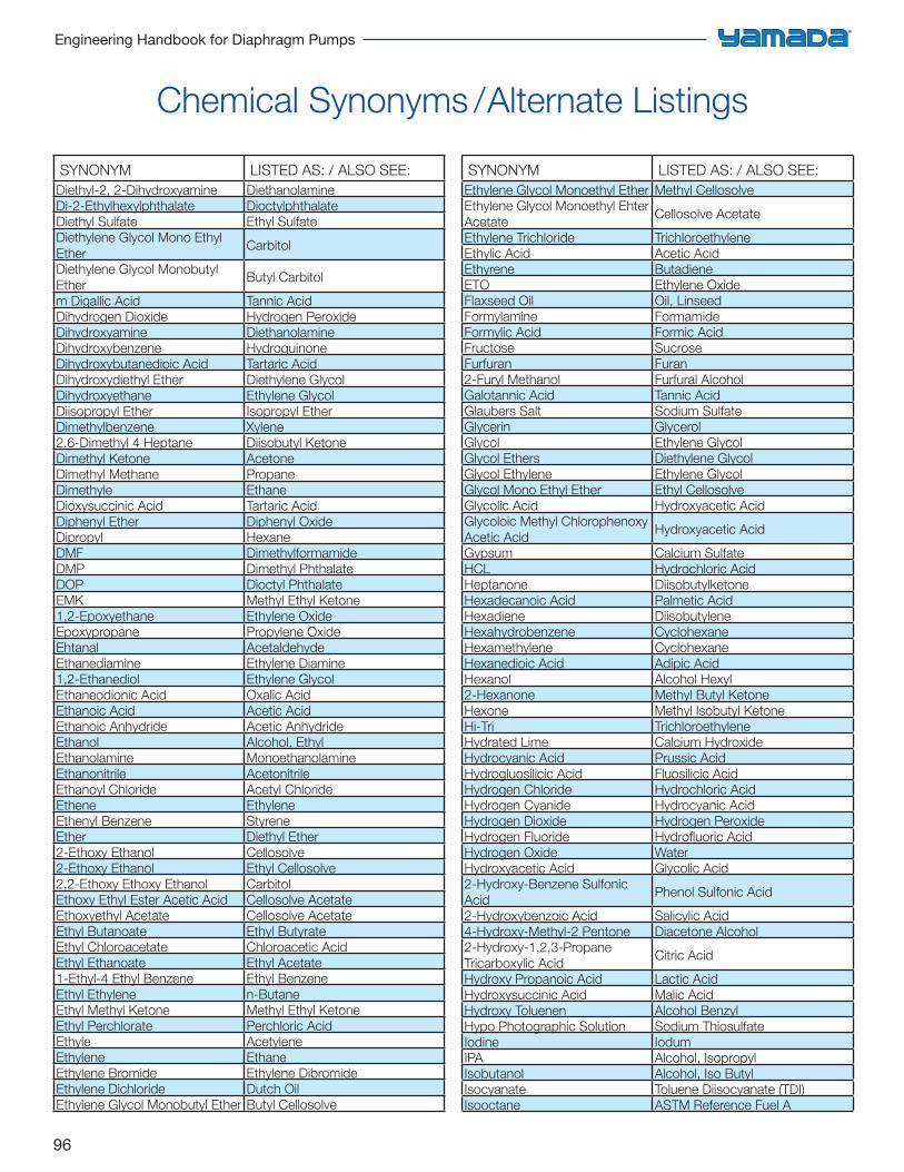
96
Engineering Handbook for Diaphragm Pumps
Chemical Synonyms /Alternate Listings
SYNONYM LISTED AS: / ALSO SEE:Diethyl-2, 2-Dihydroxyamine DiethanolamineDi-2-Ethylhexylphthalate DioctylphthalateDiethyl Sulfate Ethyl SulfateDiethylene Glycol Mono Ethyl Ether
Carbitol
Diethylene Glycol Monobutyl Ether
Butyl Carbitol
m Digallic Acid Tannic AcidDihydrogen Dioxide Hydrogen PeroxideDihydroxyamine DiethanolamineDihydroxybenzene HydroquinoneDihydroxybutanedioic Acid Tartaric AcidDihydroxydiethyl Ether Diethylene GlycolDihydroxyethane Ethylene GlycolDiisopropyl Ether Isopropyl EtherDimethylbenzene Xylene2.6-Dimethyl 4 Heptane Diisobutyl KetoneDimethyl Ketone AcetoneDimethyl Methane PropaneDimethyle EthaneDioxysuccinic Acid Tartaric AcidDiphenyl Ether Diphenyl OxideDipropyl HexaneDMF DimethylformamideDMP Dimethyl PhthalateDOP Dioctyl PhthalateEMK Methyl Ethyl Ketone1,2-Epoxyethane Ethylene OxideEpoxypropane Propylene OxideEhtanal AcetaldehydeEthanediamine Ethylene Diamine1,2-Ethanediol Ethylene GlycolEthaneodionic Acid Oxalic AcidEthanoic Acid Acetic AcidEthanoic Anhydride Acetic AnhydrideEthanol Alcohol, EthylEthanolamine MonoethanolamineEthanonitrile AcetonitrileEthanoyl Chloride Acetyl ChlorideEthene EthyleneEthenyl Benzene StyreneEther Diethyl Ether2-Ethoxy Ethanol Cellosolve2-Ethoxy Ethanol Ethyl Cellosolve2,2-Ethoxy Ethoxy Ethanol CarbitolEthoxy Ethyl Ester Acetic Acid Cellosolve AcetateEthoxyethyl Acetate Cellosolve AcetateEthyl Butanoate Ethyl ButyrateEthyl Chloroacetate Chloroacetic AcidEthyl Ethanoate Ethyl Acetate1-Ethyl-4 Ethyl Benzene Ethyl BenzeneEthyl Ethylene n-ButaneEthyl Methyl Ketone Methyl Ethyl KetoneEthyl Perchlorate Perchloric AcidEthyle AcetyleneEthylene EthaneEthylene Bromide Ethylene DibromideEthylene Dichloride Dutch OilEthylene Glycol Monobutyl Ether Butyl Cellosolve
SYNONYM LISTED AS: / ALSO SEE:Ethylene Glycol Monoethyl Ether Methyl CellosolveEthylene Glycol Monoethyl Ehter Acetate
Cellosolve Acetate
Ethylene Trichloride TrichloroethyleneEthylic Acid Acetic AcidEthyrene ButadieneETO Ethylene OxideFlaxseed Oil Oil, LinseedFormylamine FormamideFormylic Acid Formic AcidFructose SucroseFurfuran Furan2-Furyl Methanol Furfural AlcoholGalotannic Acid Tannic AcidGlaubers Salt Sodium SulfateGlycerin GlycerolGlycol Ethylene GlycolGlycol Ethers Diethylene GlycolGlycol Ethylene Ethylene GlycolGlycol Mono Ethyl Ether Ethyl CellosolveGlycolic Acid Hydroxyacetic AcidGlycoloic Methyl Chlorophenoxy Acetic Acid
Hydroxyacetic Acid
Gypsum Calcium SulfateHCL Hydrochloric AcidHeptanone DiisobutylketoneHexadecanoic Acid Palmetic AcidHexadiene DiisobutyleneHexahydrobenzene CyclohexaneHexamethylene CyclohexaneHexanedioic Acid Adipic AcidHexanol Alcohol Hexyl2-Hexanone Methyl Butyl KetoneHexone Methyl Isobutyl KetoneHi-Tri TrichloroethyleneHydrated Lime Calcium HydroxideHydrocyanic Acid Prussic AcidHydrogluosilicic Acid Fluosilicic AcidHydrogen Chloride Hydrochloric AcidHydrogen Cyanide Hydrocyanic AcidHydrogen Dioxide Hydrogen PeroxideHydrogen Fluoride Hydrofl uoric AcidHydrogen Oxide WaterHydroxyacetic Acid Glycolic Acid2-Hydroxy-Benzene Sulfonic Acid
Phenol Sulfonic Acid
2-Hydroxybenzoic Acid Salicylic Acid4-Hydroxy-Methyl-2 Pentone Diacetone Alcohol2-Hydroxy-1,2,3-Propane Tricarboxylic Acid
Citric Acid
Hydroxy Propanoic Acid Lactic AcidHydroxysuccinic Acid Malic AcidHydroxy Toluenen Alcohol BenzylHypo Photographic Solution Sodium ThiosulfateIodine IodumIPA Alcohol, IsopropylIsobutanol Alcohol, Iso ButylIsocyanate Toluene Diisocyanate (TDI)Isooctane ASTM Reference Fuel A
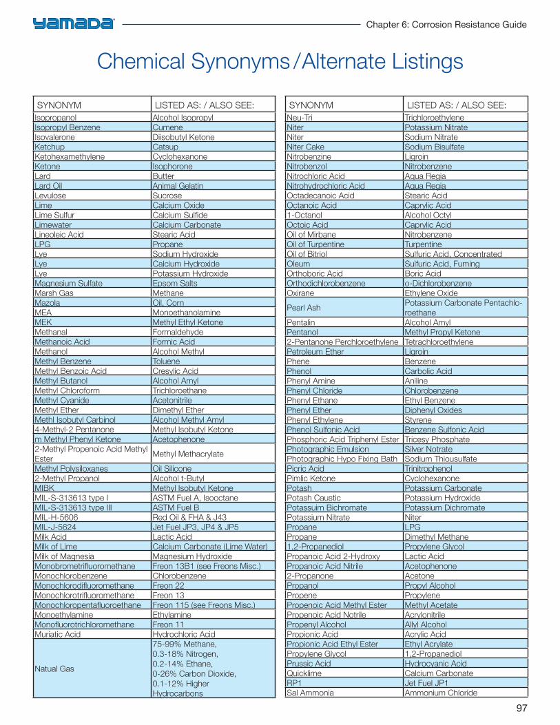
97
Chapter 6: Corrosion Resistance Guide
Chemical Synonyms /Alternate Listings
SYNONYM LISTED AS: / ALSO SEE:Isopropanol Alcohol IsopropylIsopropyl Benzene CumeneIsovalerone Diisobutyl KetoneKetchup CatsupKetohexamethylene CyclohexanoneKetone IsophoroneLard ButterLard Oil Animal GelatinLevulose SucroseLime Calcium OxideLime Sulfur Calcium Sulfi deLimewater Calcium CarbonateLineoleic Acid Stearic AcidLPG PropaneLye Sodium HydroxideLye Calcium HydroxideLye Potassium HydroxideMagnesium Sulfate Epsom SaltsMarsh Gas MethaneMazola Oil, CornMEA MonoethanolamineMEK Methyl Ethyl KetoneMethanal FormaldehydeMethanoic Acid Formic AcidMethanol Alcohol MethylMethyl Benzene TolueneMethyl Benzoic Acid Cresylic AcidMethyl Butanol Alcohol AmylMethyl Chloroform TrichloroethaneMethyl Cyanide AcetonitrileMethyl Ether Dimethyl EtherMethl Isobutyl Carbinol Alcohol Methyl Amyl4-Methyl-2 Pentanone Methyl Isobutyl Ketonem Methyl Phenyl Ketone Acetophenone2-Methyl Propenoic Acid Methyl Ester
Methyl Methacrylate
Methyl Polysiloxanes Oil Silicone2-Methyl Propanol Alcohol t-ButylMIBK Methyl Isobutyl KetoneMIL-S-313613 type I ASTM Fuel A, IsooctaneMIL-S-313613 type III ASTM Fuel BMIL-H-5606 Red Oil & FHA & J43MIL-J-5624 Jet Fuel JP3, JP4 & JP5Milk Acid Lactic AcidMilk of Lime Calcium Carbonate (Lime Water)Milk of Magnesia Magnesium HydroxideMonobrometrifl uoromethane Freon 13B1 (see Freons Misc.)Monochlorobenzene ChlorobenzeneMonochlorodifl uoromethane Freon 22Monochlorotrifl uoromethane Freon 13Monochloropentafl uoroethane Freon 115 (see Freons Misc.)Monoethylamine EthylamineMonofl uorotrichloromethane Freon 11Muriatic Acid Hydrochloric Acid
Natual Gas
75-99% Methane,0.3-18% Nitrogen,0.2-14% Ethane,0-26% Carbon Dioxide,0.1-12% HigherHydrocarbons
SYNONYM LISTED AS: / ALSO SEE:Neu-Tri TrichloroethyleneNiter Potassium NitrateNiter Sodium NitrateNiter Cake Sodium BisulfateNitrobenzine LigroinNitrobenzol NitrobenzeneNitrochloric Acid Aqua RegiaNitrohydrochloric Acid Aqua RegiaOctadecanoic Acid Stearic AcidOctanoic Acid Caprylic Acid1-Octanol Alcohol OctylOctoic Acid Caprylic AcidOil of Mirbane NitrobenzeneOil of Turpentine TurpentineOil of Bitriol Sulfuric Acid, ConcentratedOleum Sulfuric Acid, FumingOrthoboric Acid Boric AcidOrthodichlorobenzene o-DichlorobenzeneOxirane Ethylene Oxide
Pearl AshPotassium Carbonate Pentachlo-roethane
Pentalin Alcohol AmylPentanol Methyl Propyl Ketone2-Pentanone Perchloroethylene TetrachloroethylenePetroleum Ether LigroinPhene BenzenePhenol Carbolic AcidPhenyl Amine AnilinePhenyl Chloride ChlorobenzenePhenyl Ethane Ethyl BenzenePhenyl Ether Diphenyl OxidesPhenyl Ethylene StyrenePhenol Sulfonic Acid Benzene Sulfonic AcidPhosphoric Acid Triphenyl Ester Tricesy PhosphatePhotographic Emulsion Silver NotratePhotographic Hypo Fixing Bath Sodium ThiousulfatePicric Acid TrinitrophenolPimlic Ketone CyclohexanonePotash Potassium CarbonatePotash Caustic Potassium HydroxidePotassuim Bichromate Potassium DichromatePotassium Nitrate NiterPropane LPGPropane Dimethyl Methane1,2-Propanediol Propylene GlycolPropanoic Acid 2-Hydroxy Lactic AcidPropanoic Acid Nitrile Acetophenone2-Propanone AcetonePropanol Propyl AlcoholPropene PropylenePropenoic Acid Methyl Ester Methyl AcetatePropenoic Acid Notrile AcrylonitrilePropenyl Alcohol Allyl AlcoholPropionic Acid Acrylic AcidPropionic Acid Ethyl Ester Ethyl AcrylatePropylene Glycol 1,2-PropanediolPrussic Acid Hydrocyanic AcidQuicklime Calcium CarbonateRP1 Jet Fuel JP1Sal Ammonia Ammonium Chloride
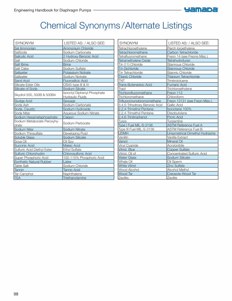
98
Engineering Handbook for Diaphragm Pumps
Chemical Synonyms /Alternate Listings
SYNONYM LISTED AS: / ALSO SEE:Sal Ammonian Ammonium ChlorideSalSoda Sodium CarbonateSalicylic Acid 2 Hydroxy Benzoic AcidSalt Sodium ChlorideSalt Brine BrineSalt Cake Sodium SulfateSaltpeter Potassium NotrateSaltpeter Sodium NotrateSand Acid Fluorosilicic AcidSilicate Ester Oils OS45 type III & IVSilicate of Soda Sodium Silcate
Skydrol 500, 500B & 500B4Isooctyl Diphenyl Phosphate Hydraulic Fluids
Sludge Acid SewageSoda Ash Sodium CarbonateSoda, Caustic Sodium HydroxideSoda Niter Aqueous Sodium NitrateSodium Hexametaphosphate CalgonSodium Metaborate Peroxyhy-drate
Sodium Perborate
Sodium Niter Sodium NitrateSodium Thiosulfate Developing FluidSoluble Glass Sodium SilicateSoya Oil Oil SoySuccinic Acid Maleic AcidSulfuric Acid Diethyl Ester Ethyl SulfateSulfuric Chlorohydrin Chlorosulfonic AcidSuper Phosphoric Acid 100-115% Phosphoric AcidSynthetic Natural Rubber LatexTable Salt Sodium ChlorideTannin Tannic AcidTar Camphor NaphthaleneTEA Triethanolamine
SYNONYM LISTED AS: / ALSO SEE:Tetrachloroethylene Perch IoroethyleneTetrachloromethane Carbon TetrachlorideTetrafl uoromethane Freon 14 (see Freons Misc.)Tetramethylene Oxide TetrahydrofuranTin (11) Chloride Stannous ChlorideTin Dichloride Stannous ChlorideTin Tetrachloride Stannic ChlorideTitanic Chloride Titanium TetrachlorideTNT TrinitrotolueneTrans-Butenedoic Acid Fumaric AcidTraid TrichloroethyleneTrichlorofl uoromethane Freon 113Trichloromethane ChloroformTrifl uoromonobromomethane Freon 13131 (see Freon Misc.)3,4,5-Trihydroxy Benzoic Acid Gallic Acid2,2,4-Trimethyl Pentane Isooctane 100%2,2,4-Trimethyl Pentane Diisobutylene2,4,6-Trinitrophenol Picric AcidTurps TurpentineType I Fuel MIL-S-3136 ASTM Reference Fuel AType III Fuel MIL-S-3136 ASTM Reference Fuel BUDMH Unsymetrical Dimethyl HydrazineVanillin Vanilla ExtractVarsol Mineral OilVinyl Cyanide AcrylonitrileVitriol, Blue Copper SulfateVitriol, Oil of Concentrated Sulfuric AcidWater Glass Sodium SilicateWhale Oil Oil SpermWhite Vitriol Zinc SulfateWood Alcohol Alcohol MethylWood Tar Creosote-Wood TarZeolitic Zeolite
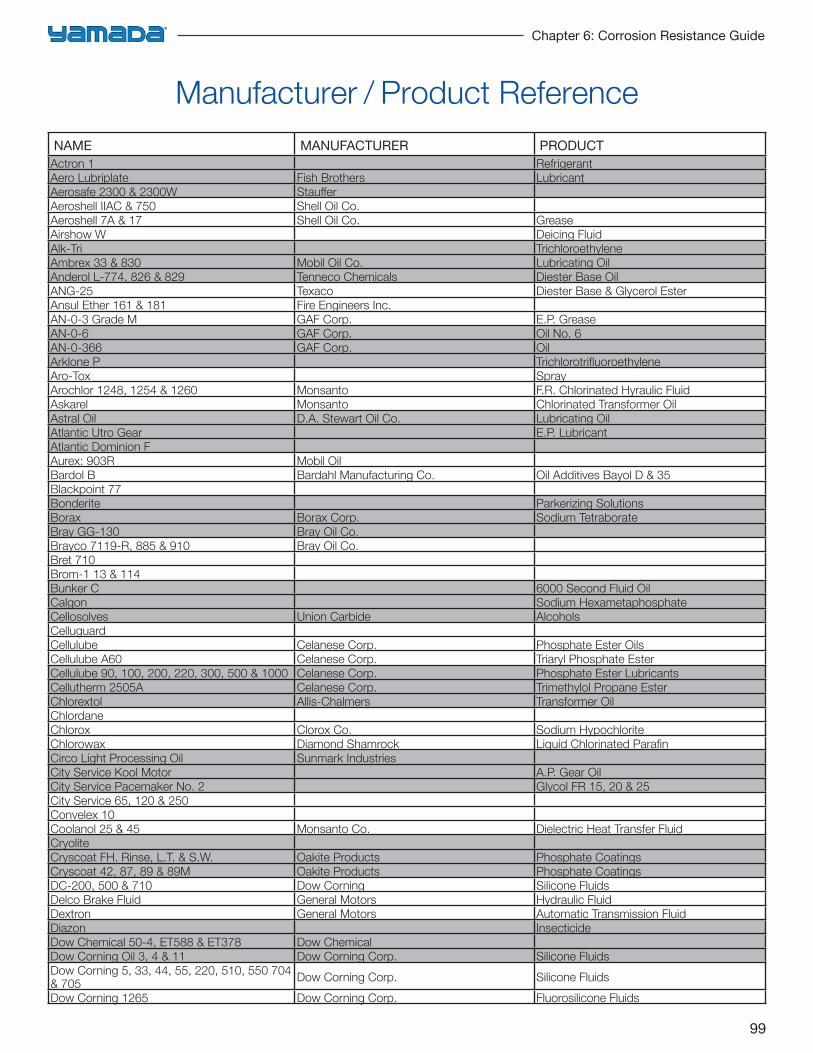
99
Chapter 6: Corrosion Resistance Guide
Manufacturer / Product ReferenceNAME MANUFACTURER PRODUCT
Actron 1 RefrigerantAero Lubriplate Fish Brothers LubricantAerosafe 2300 & 2300W Stauff erAeroshell IIAC & 750 Shell Oil Co.Aeroshell 7A & 17 Shell Oil Co. GreaseAirshow W Deicing FluidAlk-Tri TrichloroethyleneAmbrex 33 & 830 Mobil Oil Co. Lubricating OilAnderol L-774, 826 & 829 Tenneco Chemicals Diester Base OilANG-25 Texaco Diester Base & Glycerol EsterAnsul Ether 161 & 181 Fire Engineers Inc.AN-0-3 Grade M GAF Corp. E.P. GreaseAN-0-6 GAF Corp. Oil No. 6AN-0-366 GAF Corp. OilArklone P Trichlorotrifl uoroethyleneAro-Tox SprayArochlor 1248, 1254 & 1260 Monsanto F.R. Chlorinated Hyraulic FluidAskarel Monsanto Chlorinated Transformer OilAstral Oil D.A. Stewart Oil Co. Lubricating OilAtlantic Utro Gear E.P. LubricantAtlantic Dominion FAurex: 903R Mobil OilBardol B Bardahl Manufacturing Co. Oil Additives Bayol D & 35Blackpoint 77Bonderite Parkerizing SolutionsBorax Borax Corp. Sodium TetraborateBray GG-130 Bray Oil Co.Brayco 7119-R, 885 & 910 Bray Oil Co.Bret 710Brom-1 13 & 114Bunker C 6000 Second Fluid OilCalgon Sodium HexametaphosphateCellosolves Union Carbide AlcoholsCelluguardCellulube Celanese Corp. Phosphate Ester OilsCellulube A60 Celanese Corp. Triaryl Phosphate EsterCellulube 90, 100, 200, 220, 300, 500 & 1000 Celanese Corp. Phosphate Ester LubricantsCellutherm 2505A Celanese Corp. Trimethylol Propane EsterChlorextol Allis-Chalmers Transformer OilChlordaneChlorox Clorox Co. Sodium HypochloriteChlorowax Diamond Shamrock Liquid Chlorinated Parafi nCirco Light Processing Oil Sunmark IndustriesCity Service Kool Motor A.P. Gear OilCity Service Pacemaker No. 2 Glycol FR 15, 20 & 25City Service 65, 120 & 250Convelex 10Coolanol 25 & 45 Monsanto Co. Dielectric Heat Transfer FluidCryoliteCryscoat FH. Rinse, L.T. & S.W. Oakite Products Phosphate CoatingsCryscoat 42, 87, 89 & 89M Oakite Products Phosphate CoatingsDC-200, 500 & 710 Dow Corning Silicone FluidsDelco Brake Fluid General Motors Hydraulic FluidDextron General Motors Automatic Transmission FluidDiazon InsecticideDow Chemical 50-4, ET588 & ET378 Dow ChemicalDow Corning Oil 3, 4 & 11 Dow Corning Corp. Silicone FluidsDow Corning 5, 33, 44, 55, 220, 510, 550 704 & 705 Dow Corning Corp. Silicone Fluids
Dow Corning 1265 Dow Corning Corp. Fluorosilicone Fluids

100
Engineering Handbook for Diaphragm Pumps
Manufacturer / Product ReferenceNAME MANUFACTURER PRODUCT
Dow Corning 1208, 4050, 6620, F-60 & XF-60 Dow Corning Corp. Chlorinated Silicone FluidDow Corning F-61 Dow Corning Corp.Dow General Weed Killer Dow Chemical Phenol & Water Base Weed KillerDow Gage Fluid R-200 Pressure Gage FluidDow Per Dow Chemical Co. Dry Cleaning FluidDow Purifl oc C-31 Dow Chemical Co.Dowanols Dow Chemical Co. Glycol Ethers
Dowtherm A Dow Chemical Co. Heat Transfer Fluid 26.5% Diphenyl, 73.5% Diphenyl Oxid
Dowtherm B Dow Chemical Co.Dowtherm E & 209 Dow Chemical Co. Heat Transfer FluidDowtherm S.R. I Dow Chemical Co. Heat Transfer FluidDrinox Morton Chemical Co.DTE 23-26 & 950 Mobil Oil Light, Medium & Heavy Hydraulic OilsDTE Light Oil Mobil Oil Lubricating OilDuco, Paint Thinner Dupont Co. Paint ThinnerElco 28 Detrex Chemical Industries E.P. LubricantEsso Fuel 208 Exxon Corp.Esso Golden Gasoline Exxon Corp. GasolineEsso Transmission Fluid Exxon Corp. Automatic Transmission FluidEsso WS2812 Exxon Corp. MIL-L-7808AEsso XP90 Exxon Corp. E.P. LubricantEsso Turbo Oil Exxon Corp. Turbine Oil Esstic 42 & 43Ex-Tri Exxon Corp. Ethylene TrichlorideExxon 2380 Turbo Oil Dow Corning Turbine Oil F-60 & 61FC-43 Heptacosofl ourotributylamineFC75 3M Co. FluorocarbonFluorolube Hooker Chemical Co.Freon E.I. Du Pont Co. Fluorocarbon RefrigerantsFyrquel 90, 100, 150, 220, 300, 500, 550 & A60 Stauff er Chemical F.R. Hydraulic Fluids
Genesolve D Allied Signal Trichlorotrifl uoroethaneGenesolve 2000 Allied Signal Solvent HCFC 141 BGenklene IcI Chlorinated (1,1,1-Trichloroethane)Girling Brake Fluid Lucas Service Brake FluidGulf Endurance Oils Gulf Refi ning Lubricating OilGulf FR Fluids Gulf Refi ning F.R. FluidsGulf FR G-Fluids G100, 150, 200 & 250 Gulf Refi ning F.R. FluidsGulf FIR P-Fluids P37, 40, 43, 45 & 47 Gulf Refi ning F.R. FluidsGulf Harmony Oils Gulf Refi ning OilsGulf High Temeprature Grease Gulf Refi ning H.T. GreaseGulf Legion Oils Gulf Refi ning OilsGulf Paramont Oils Gulf Refi ning OilsGulf Security Oils Gulf Refi ning OilsGulfcrown Grease Gulf Refi ning GreaseHannifi n Lube A Paker Hannifi nHi-Lo MS No. 1Hi-Tri Ethylene TrichlorideHollingshead H-2 E.F. Houghton & Co. Water & Ethylene GlycolHoughto-Safe 271 & 600 E.F. Houghton & Co. MIL-H-27072 Water & Glycol BaseHoughto-Safe 271 & 600 E.F. Houghton & Co. Water & Glycol Based MIL-H-27072Houghto-Safe 416 & 500 E.F. Houghton & Co.Houghto-Safe 1010, 1120 E.F. Houghton & Co. MIL-H-19547 Phosphate Ester BaseHoughto-Safe 5040 E.F. Houghton & Co. Water & Oil EmulsionHoughto-Safe 5040 E.F. Houghton & Co. Petroleum BaseHydro-Drive MIH50 & MIH10 E.F. Houghton & Co. Petroleum BaseHydrolube Water & Ethylene GlycolHypoid Lubes Hypoid Gear E.P. LubesHy Kil No. 6Hyjet Chevron Phosphate EsterIgepal Gaf Surfactant
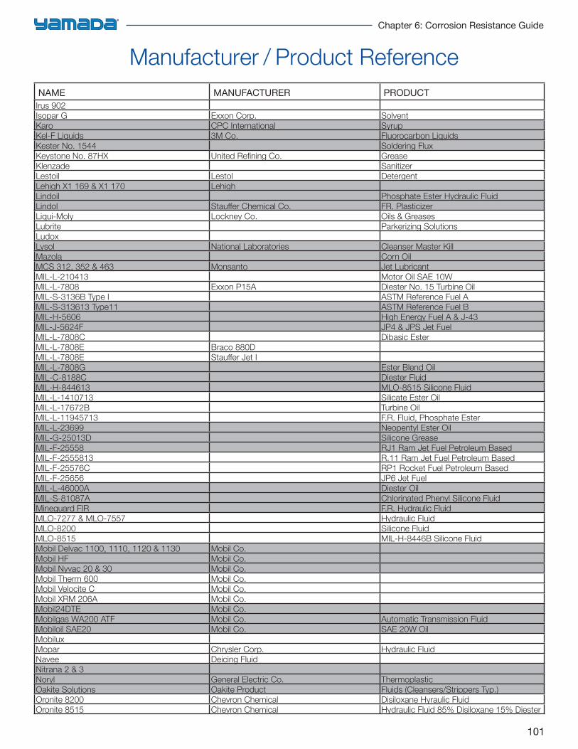
101
Chapter 6: Corrosion Resistance Guide
Manufacturer / Product ReferenceNAME MANUFACTURER PRODUCT
Irus 902Isopar G Exxon Corp. SolventKaro CPC International SyrupKel-F Liquids 3M Co. Fluorocarbon LiquidsKester No. 1544 Soldering FluxKeystone No. 87HX United Refi ning Co. GreaseKlenzade SanitizerLestoil Lestol DetergentLehigh X1 169 & X1 170 LehighLindoil Phosphate Ester Hydraulic FluidLindol Stauff er Chemical Co. FR. PlasticizerLiqui-Moly Lockney Co. Oils & GreasesLubrite Parkerizing SolutionsLudoxLysol National Laboratories Cleanser Master KillMazola Corn OilMCS 312, 352 & 463 Monsanto Jet LubricantMIL-L-210413 Motor Oil SAE 10WMIL-L-7808 Exxon P15A Diester No. 15 Turbine OilMIL-S-3136B Type I ASTM Reference Fuel AMIL-S-313613 Type11 ASTM Reference Fuel BMIL-H-5606 High Energy Fuel A & J-43MIL-J-5624F JP4 & JPS Jet FuelMIL-L-7808C Dibasic EsterMIL-L-7808E Braco 880DMIL-L-7808E Stauff er Jet IMIL-L-7808G Ester Blend OilMIL-C-8188C Diester FluidMIL-H-844613 MLO-8515 Silicone FluidMIL-L-1410713 Silicate Ester OilMIL-L-17672B Turbine OilMIL-L-11945713 F.R. Fluid, Phosphate EsterMIL-L-23699 Neopentyl Ester OilMIL-G-25013D Silicone GreaseMIL-F-25558 RJ1 Ram Jet Fuel Petroleum BasedMIL-F-2555813 R.11 Ram Jet Fuel Petroleum BasedMIL-F-25576C RP1 Rocket Fuel Petroleum BasedMIL-F-25656 JP6 Jet FuelMIL-L-46000A Diester OilMIL-S-81087A Chlorinated Phenyl Silicone FluidMineguard FIR F.R. Hydraulic FluidMLO-7277 & MLO-7557 Hydraulic FluidMLO-8200 Silicone FluidMLO-8515 MIL-H-8446B Silicone FluidMobil Delvac 1100, 1110, 1120 & 1130 Mobil Co.Mobil HF Mobil Co.Mobil Nyvac 20 & 30 Mobil Co.Mobil Therm 600 Mobil Co.Mobil Velocite C Mobil Co.Mobil XRM 206A Mobil Co.Mobil24DTE Mobil Co.Mobilgas WA200 ATF Mobil Co. Automatic Transmission FluidMobiloil SAE20 Mobil Co. SAE 20W OilMobiluxMopar Chrysler Corp. Hydraulic FluidNavee Deicing FluidNitrana 2 & 3Noryl General Electric Co. ThermoplasticOakite Solutions Oakite Product Fluids (Cleansers/Strippers Typ.)Oronite 8200 Chevron Chemical Disiloxane Hyraulic FluidOronite 8515 Chevron Chemical Hydraulic Fluid 85% Disiloxane 15% Diester
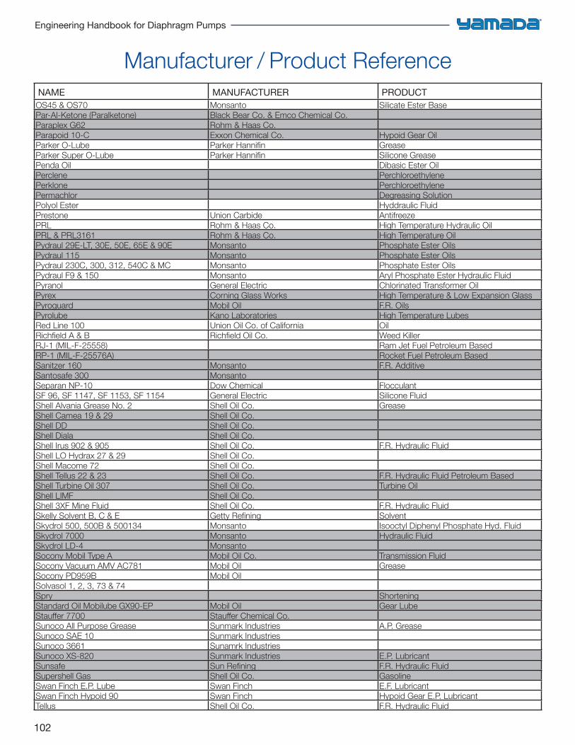
102
Engineering Handbook for Diaphragm Pumps
NAME MANUFACTURER PRODUCTOS45 & OS70 Monsanto Silicate Ester BasePar-Al-Ketone (Paralketone) Black Bear Co. & Emco Chemical Co.Paraplex G62 Rohm & Haas Co.Parapoid 10-C Exxon Chemical Co. Hypoid Gear OilParker O-Lube Parker Hannifi n GreaseParker Super O-Lube Parker Hannifi n Silicone GreasePenda Oil Dibasic Ester OilPerclene PerchloroethylenePerklone PerchloroethylenePermachlor Degreasing SolutionPolyol Ester Hyddraulic FluidPrestone Union Carbide AntifreezePRL Rohm & Haas Co. High Temperature Hydraulic OilPRL & PRL3161 Rohm & Haas Co. High Temperature OilPydraul 29E-LT, 30E, 50E, 65E & 90E Monsanto Phosphate Ester OilsPydraul 115 Monsanto Phosphate Ester OilsPydraul 230C, 300, 312, 540C & MC Monsanto Phosphate Ester OilsPydraul F9 & 150 Monsanto Aryl Phosphate Ester Hydraulic FluidPyranol General Electric Chlorinated Transformer OilPyrex Corning Glass Works High Temperature & Low Expansion GlassPyroguard Mobil Oil F.R. OilsPyrolube Kano Laboratories High Temperature LubesRed Line 100 Union Oil Co. of California OilRichfi eld A & B Richfi eld Oil Co. Weed KillerRJ-1 (MIL-F-25558) Ram Jet Fuel Petroleum BasedRP-1 (MIL-F-25576A) Rocket Fuel Petroleum BasedSanitzer 160 Monsanto F.R. AdditiveSantosafe 300 MonsantoSeparan NP-10 Dow Chemical FlocculantSF 96, SF 1147, SF 1153, SF 1154 General Electric Silicone FluidShell Alvania Grease No. 2 Shell Oil Co. GreaseShell Camea 19 & 29 Shell Oil Co.Shell DD Shell Oil Co.Shell Diala Shell Oil Co.Shell Irus 902 & 905 Shell Oil Co. F.R. Hydraulic FluidShell LO Hydrax 27 & 29 Shell Oil Co.Shell Macome 72 Shell Oil Co.Shell Tellus 22 & 23 Shell Oil Co. F.R. Hydraulic Fluid Petroleum BasedShell Turbine Oil 307 Shell Oil Co. Turbine OilShell LIMF Shell Oil Co.Shell 3XF Mine Fluid Shell Oil Co. F.R. Hydraulic FluidSkelly Solvent B, C & E Getty Refi ning SolventSkydrol 500, 500B & 500134 Monsanto Isooctyl Diphenyl Phosphate Hyd. FluidSkydrol 7000 Monsanto Hydraulic FluidSkydrol LD-4 MonsantoSocony Mobil Type A Mobil Oil Co. Transmission FluidSocony Vacuum AMV AC781 Mobil Oil GreaseSocony PD959B Mobil OilSolvasol 1, 2, 3, 73 & 74Spry ShorteningStandard Oil Mobilube GX90-EP Mobil Oil Gear LubeStauff er 7700 Stauff er Chemical Co.Sunoco All Purpose Grease Sunmark Industries A.P. GreaseSunoco SAE 10 Sunmark IndustriesSunoco 3661 Sunamrk IndustriesSunoco XS-820 Sunmark Industries E.P. LubricantSunsafe Sun Refi ning F.R. Hydraulic FluidSupershell Gas Shell Oil Co. GasolineSwan Finch E.P. Lube Swan Finch E.F. LubricantSwan Finch Hypoid 90 Swan Finch Hypoid Gear E.P. LubricantTellus Shell Oil Co. F.R. Hydraulic Fluid
Manufacturer / Product Reference
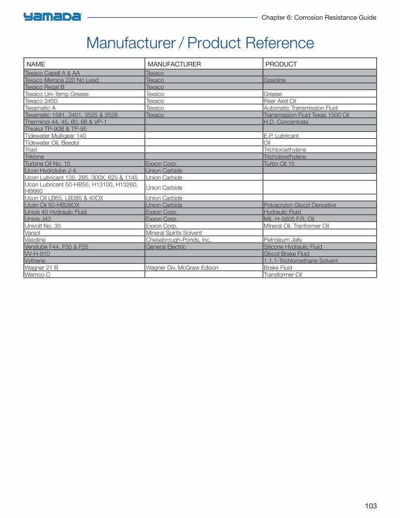
103
Chapter 6: Corrosion Resistance Guide
NAME MANUFACTURER PRODUCTTexaco Capell A & AA TexacoTexaco Meropa 220 No Lead Texaco GasolineTexaco Regal B TexacoTexaco Uni-Temp Grease Texaco GreaseTexaco 3450 Texaco Rear Axel OilTexamatic A Texaco Automatic Transmission FluidTexamatic 1581, 3401, 3525 & 3528 Texaco Transmission Fluid Texas 1500 OilTherminol 44, 45, 60, 66 & VP-1 H.D. ConcentrateThiokol TP-90B & TP-95Tidewater Multigear 140 E.P. LubricantTidewater Oil, Beedol OilTriad TrichloroethyleneTriklone TricholorethyleneTurbine Oil No. 15 Exxon Corp. Turbo Oil 15Ucon Hydrolube J-4 Union CarbideUcon Lubricant 135, 285, 300X, 625 & 1145 Union CarbideUcon Lubricant 50-HB55, H13100, H13260, HB660 Union Carbide
Ucon Oil LB65, LB385 & 40OX Union CarbideUcon Oil 50-HB28OX Union Carbide Polyacrylon Glycol DerivativeUnivis 40 Hydraulic Fluid Exxon Corp. Hydraulic FluidUnivis J43 Exxon Corp. MIL-H-5605 F.R. OilUnivolt No. 35 Exxon Corp. Mineral Oil, Tranformer OilVarsol Mineral Spirits SolventVasoline Chesebrough-Ponds, Inc. Petroleum JellyVersilube F44, F50 & F55 General Electric Silicone Hydraulic FluidVV-H-910 Glycol Brake FluidVythene 1,1,1-Trichloroethane SolventWagner 21 B Wagner Div. McGraw Edison Brake FluidWemco C Transformer Oil
Manufacturer / Product Reference
104
Engineering Handbook for Diaphragm Pumps
Choosing a pump for long, trouble free service not only requires selecting the correct pump size for capacity and head conditions; but proper wetted and non-wetted components must be taken into consideration.Pump components are subject to wear simply through everyday use. However, a majority of pump failures can be attributed to improper wetted components due to abrasive wear and chemical attack. The selection of wetted and non-wetted components requires knowing how to properly handle abrasive, non-lubricating fluids. Additional attention must be given to the correct materials of construction for corrosive handling of the product and the atmospheric conditions where the pump will be installed.
Compatibility
The use of chemical compatibility charts can help in the proper selection of components for the pump’s construction. These charts are meant as a guideline and not intended as a guarantee of performance. In many cases, practical experience and past history can dictate the materials of construction.In using chemical compatibility charts, it is best to select the material with an A or B rating. However, with fluids that are slightly aggressive, it may be advantageous, from a service life/dollar viewpoint, to choose a material that will provide compatibility (possibly a B rating) at a lower cost with satisfactory results.As an example, a diaphragm pump customer handling Amyl-Alcohol, referring to chemical resistance chart, with select PTFE because of the “A” rating for compatibility. However, PTFE has a lower flex life compared to Neoprene, which has a “B” rating for this product. Though a “B” rating may indicate Neoprene has a “good” rating, it does imply there may be some lower flex life, or compatibility issues, also. When comparing the cost of PTFE vs. Neoprene, the Neoprene material may reach its mean flex life as that of the PTFE material. The cost replacement factor would dictate this would be a better choice. When a lesser rated material offers the same life expectancy as the “preferred” materials, it may be a viable alternative for the investment. In this case, the price of PTFE would be quadruple that of Neoprene.
Erosion and Abrasives
In selecting pump components subject to corrosive fluids at high velocities, erosion will occur faster than lower velocities. Erosion is accelerated by corrosion.
When faced with choosing a “B” rated material versus an “A”, the effects of erosion, as related to specific pump components, should be taken into consideration.A common misconception when handling abrasives and suspended solids is the sharpness, or ability to cut. When selecting diaphragm and ball valve materials, sharp particulates can have a tendency to cut the PTFE diaphragm, and embed into the PTFE ball valves. Incorporating metallic valve seats with PTFE balls, embedded solids can quickly wear valve seat and ball retainers. However, elastomeric ball valves and seats are more resilient and will permit the sharp particulates to “bounce” or reflect off the surface. This can greatly reduce wear.The hardness of the ball valve and seat arrangement can greatly affect the pump’s ability to pull a vacuum. A hard ball valve with a hard (PTFE or metallic) valve seat can be noisy and will greatly reduce the pump’s ability to pull a vacuum compared to a softer elastomeric combination. The application should dictate the choice of the materials of construction. On high static lifts, location of the pump is essential to avoid cavitation.
Pump Sizing Selection
A commonly used statement with positive displacement pumps is, “oversize, operate slower”. While there is some merit to this, there must be some degree of knowledge of the application and equipment being used. There is no doubt that a larger pump operating at lower speeds (while meeting all application criteria) will provide longer service than a smaller pump running at higher speeds. However, considering the competitive marketplace, which the user and manufacturer face, it is not practical, or financially beneficial, to substitute a larger pump for smaller. But, when the service life versus investment ration becomes too high, the purchase of a larger pump can be justified. Unfortunately, due to the consideration of losing business or exceeding a budgetary plan, many pumps are specified and sold based solely on the initial investment portion of the equation. These scenarios are typical when selecting materials of construction. But, decisions should be based on the material’s estimated life expectancy, downtime, complexity of repair, and cost. Performance and longevity should not be sacrificed for economics when specifying and selecting the right pump for the application.
Choosing the Right Pump
105
Chapter 7: Air Data
Horsepower Requirements 106
The Gas Laws 107
Compressed Air Quality and Hints on Installation 109
Moisture/Dewpoint 110
Air Line Pipe Sizes 111
Air Pressure Loss 111
Estimating Air Flow Loss Through Pipes 112
Air Friction Loss 60–80lb Gauge 113
Air Friction Loss 100–125lb Gauge 114
Air Flow Through Orifices 115
Vacuum Flow Through Orifices 115
CV Information 116
Air Data
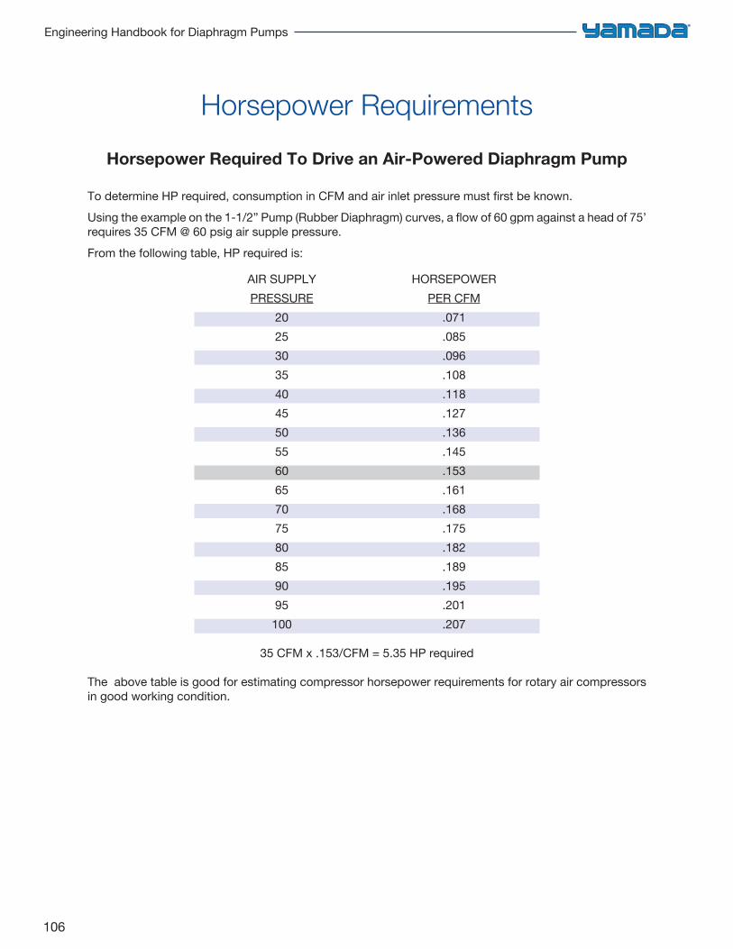
106
Engineering Handbook for Diaphragm Pumps
Horsepower Required To Drive an Air-Powered Diaphragm Pump
To determine HP required, consumption in CFM and air inlet pressure must first be known.Using the example on the 1-1/2” Pump (Rubber Diaphragm) curves, a flow of 60 gpm against a head of 75’ requires 35 CFM @ 60 psig air supple pressure.From the following table, HP required is:
AIR SUPPLY HORSEPOWERPRESSURE PER CFM
20 .07125 .08530 .09635 .10840 .11845 .12750 .13655 .14560 .15365 .16170 .16875 .17580 .18285 .18990 .19595 .201100 .207
35 CFM x .153/CFM = 5.35 HP required
The above table is good for estimating compressor horsepower requirements for rotary air compressors in good working condition.
Horsepower Requirements
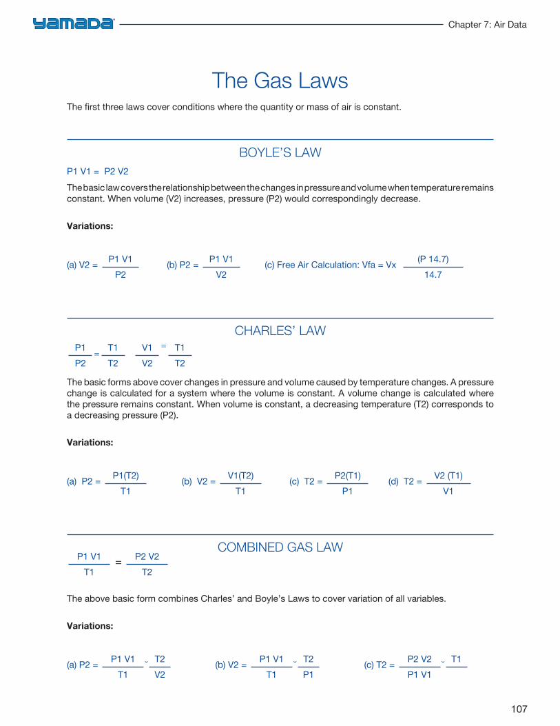
107
Chapter 7: Air Data
The Gas LawsThe first three laws cover conditions where the quantity or mass of air is constant.
BOYLE’S LAWP1 V1 = P2 V2The basic law covers the relationship between the changes in pressure and volume when temperature remains constant. When volume (V2) increases, pressure (P2) would correspondingly decrease.
Variations:
(a) V2 = P1 V1P2
(b) P2 = P1 V1V2
(c) Free Air Calculation: Vfa = Vx (P 14.7)14.7
CHARLES’ LAW
The basic forms above cover changes in pressure and volume caused by temperature changes. A pressure change is calculated for a system where the volume is constant. A volume change is calculated where the pressure remains constant. When volume is constant, a decreasing temperature (T2) corresponds to a decreasing pressure (P2).
Variations:
(a) P2 = P1(T2)T1
(b) V2 = V1(T2)T1
(c) T2 = P2(T1)P1
(d) T2 = V2 (T1)V1
COMBINED GAS LAW
The above basic form combines Charles’ and Boyle’s Laws to cover variation of all variables.
Variations:
(a) P2 = P1 V1T1
˘ T2V2
(b) V2 = P1 V1T1
˘ T2P1
(c) T2 = P2 V2P1 V1
˘ T1--
P1 V1T1
= P2 V2T2
P1P2
=T1T2
V1V2
= T1T2
108
Engineering Handbook for Diaphragm Pumps
NOMENCLATUREP1 = inlet absolute pressureP2 = discharge absolute pressureV1 = inlet volumeV2 = discharge volumeT1 = inlet absolute temperatureT2 = discharge absolute temperaturem = mass
FLOW MEASUREMENTSThe volume of air delivered by a compressor or removed by a vacuum pump is given in either cubic feet of free air per minute (cfm) or in standard cubic feet of air per minute (scfm). SCFM is under standard conditions which is used on most air operated pump curves.
FREE AIRThis is air at atmospheric pressure and ambient temperature. Free air volume (cfm) is obtained by using the gas laws to convert volume at atmospheric pressure and ambient temperature.
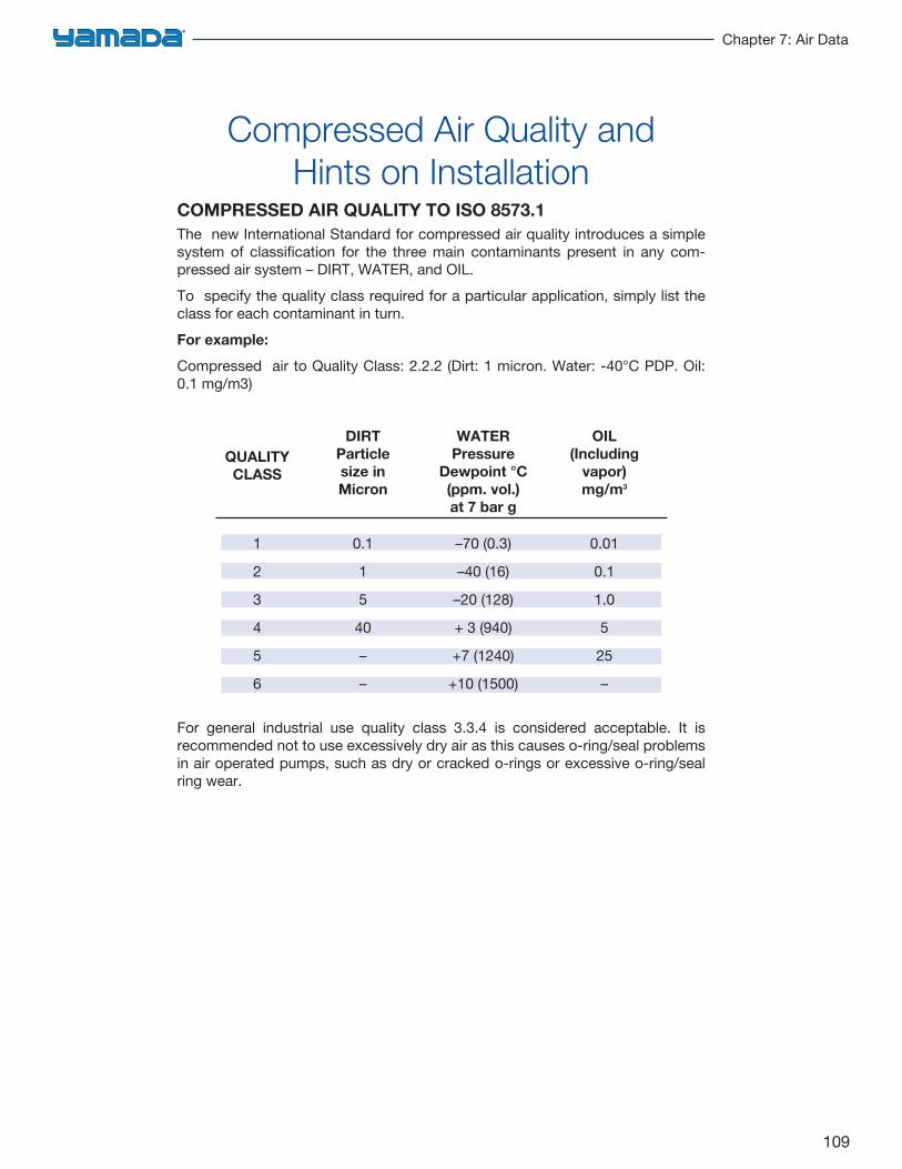
109
Chapter 7: Air Data
Compressed Air Quality and Hints on Installation
COMPRESSED AIR QUALITY TO ISO 8573.1The new International Standard for compressed air quality introduces a simple system of classification for the three main contaminants present in any com-pressed air system – DIRT, WATER, and OIL.To specify the quality class required for a particular application, simply list the class for each contaminant in turn.For example:
Compressed air to Quality Class: 2.2.2 (Dirt: 1 micron. Water: -40°C PDP. Oil: 0.1 mg/m3)
QUALITYDIRT WATER OIL
CLASS Particle Pressure (Including
size in Dewpoint °C vapor)Micron (ppm. vol.) mg/m3
at 7 bar g
1 0.1 –70 (0.3) 0.01
2 1 –40 (16) 0.1
3 5 –20 (128) 1.0
4 40 + 3 (940) 5
5 – +7 (1240) 25
6 – +10 (1500) –
For general industrial use quality class 3.3.4 is considered acceptable. It is recommended not to use excessively dry air as this causes o-ring/seal problems in air operated pumps, such as dry or cracked o-rings or excessive o-ring/seal ring wear.
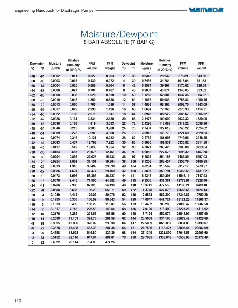
110
Engineering Handbook for Diaphragm Pumps
Moisture/Dewpoint8 BAR ABSOLUTE (7 BAR G)
Dewpoint °C °F
-70 -94 -68 -90 -66 -87 -64 -83 -62 -80 -60 -76 -58 -72 -56 -69 -54 -65 -52 -62 -50 -58 -48 -54 -46 -51 -44 -47 -42 -44 -40 -40 -38 -36 -36 -33 -34 -29 -32 -26 -30 -22 -28 -18 -26 -15 -24 -11 -22 -8 -20 -4 -18 0 -16 3 -14 7 -12 10 -10 14 -8 18 -6 21 -4 25 -2 28 0 32
Moisture(g/m3)
0.00020.00030.00040.00060.00080.00100.00130.00170.00220.00280.00360.00460.00590.00740.00930.01170.01640.02040.02540.03130.03860.04730.05790.07060.08580.10390.12550.15130.18170.21760.25980.30950.36780.43580.51520.6022
RelativeHumidity
at 20°C; %0.0110.0150.0200.0270.0350.0460.0600.0790.1020.1310.168.02150.2730.3460.4370.5490.6870.8561.0621.3161.6241.9962.4452.9863.6354.4125.3366.4397.7439.286
11.10312.85615.49818.69222.11626.114
PPMvolume
0.3270.4390.5860.7841.0281.3501.7662.2982.9753.8344.9196.2837.991
10.12112.76316.03820.07525.02631.10138.48947.47758.36671.50587.320106.29129.02156.02188.29226.43271.57324.73376.02453.33546.80647.04764.08
PPMweight
0.2030.2720.3640.4870.6380.8381.0961.4261.8472.3803.0533.9004.9606.2827.9229.954
12.46115.53319.30423.89029.46936.22744.38254.19965.97180.07996.843116.87140.54168.56201.56233.38281.38339.39401.61474.26
Dewpoint °C °F
2 36 4 39 6 42 8 46 10 50 12 54 14 57 16 60 18 64 20 68 22 72 24 75 26 79 28 82 30 86 32 90 34 93 36 97 38 100 40 104 42 108 44 111 46 115 48 118 50 122 52 126 54 129 56 133 58 136 60 140 62 144 64 147 66 151 68 154 70 158
Moisture(g/m
3
)
0.64150.74560.85740.98371.12601.28671.46681.66911.89462.14772.42962.74313.09193.47893.90804.38214.90595.48356.12066.82047.58978.43469.3556
10.371111.474512.685314.004715.443217.012018.712420.565822.583924.759627.134929.7035
RelativeHumidity
at 20°C; %29.93234.78439.99145.87452.50159.98368.36377.76888.243
100.000113.083127.619143.779161.693181.531203.420227.576254.168283.454315.562350.791389.397431.381477.555527.576582.300641.727706.285776.400852.074934.160
1023.0871118.4271221.8901333.048
PPMvolume
875.891018.041170.621343.051537.361756.832002.752278.932586.672932.323317.223745.224221.504749.965335.825983.086698.327486.898356.769312.17
10362.5311516.1112773.6114160.2115666.6617319.8719121.2621085.4223227.2625548.9928079.4230834.8533805.4437048.5640555.66
PPMweight
543.66631.88726.59833.62954.22
1090.451243.091414.511605.521820.062058.962324.622620.242948.253311.893713.644157.585657.035186.955779.976431.927147.937928.468789.109724.13
10750.2611868.3713087.5014416.9215857.9917428.6019138.8720982.6922995.6625172.48
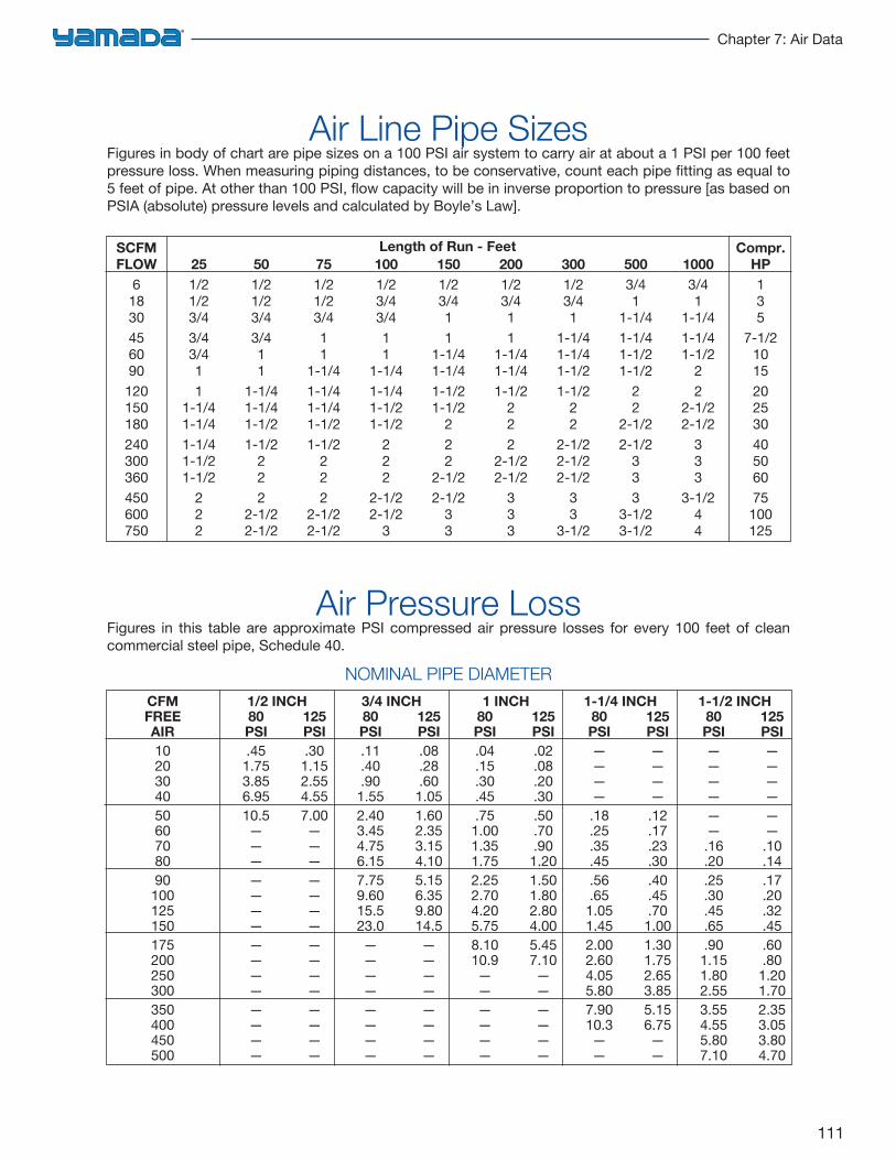
111
Chapter 7: Air Data
Air Line Pipe SizesFigures in body of chart are pipe sizes on a 100 PSI air system to carry air at about a 1 PSI per 100 feet pressure loss. When measuring piping distances, to be conservative, count each pipe fitting as equal to 5 feet of pipe. At other than 100 PSI, flow capacity will be in inverse proportion to pressure [as based on PSIA (absolute) pressure levels and calculated by Boyle’s Law].
SCFMFLOW
61830456090120150180240300360450600750
251/21/23/43/43/411
1-1/41-1/41-1/41-1/21-1/2
222
501/21/23/43/411
1-1/41-1/41-1/21-1/2
222
2-1/22-1/2
751/21/23/411
1-1/41-1/41-1/41-1/21-1/2
222
2-1/22-1/2
1001/23/43/411
1-1/41-1/41-1/21-1/2
222
2-1/22-1/2
3
1501/23/411
1-1/41-1/41-1/21-1/2
222
2-1/22-1/2
33
2001/23/411
1-1/41-1/41-1/2
222
2-1/22-1/2
333
3001/23/41
1-1/41-1/41-1/21-1/2
22
2-1/22-1/22-1/2
33
3-1/2
5003/41
1-1/41-1/41-1/21-1/2
22
2-1/22-1/2
333
3-1/23-1/2
10003/41
1-1/41-1/41-1/2
22
2-1/22-1/2
333
3-1/244
Compr.HP135
7-1/2101520253040506075100125
Length of Run - Feet
Air Pressure LossFigures in this table are approximate PSI compressed air pressure losses for every 100 feet of clean commercial steel pipe, Schedule 40.
NOMINAL PIPE DIAMETER
CFMFREEAIR102030405060708090
100125150175200250300350400450500
1/2 INCH 80 125 PSI PSI .45 .30 1.75 1.15 3.85 2.55 6.95 4.55 10.5 7.00 — — — — — — — — — — — — — — — — — — — — — — — — — — — — — —
3/4 INCH 80 125 PSI PSI .11 .08 .40 .28 .90 .60 1.55 1.05 2.40 1.60 3.45 2.35 4.75 3.15 6.15 4.10 7.75 5.15 9.60 6.35 15.5 9.80 23.0 14.5 — — — — — — — — — — — — — — — —
1 INCH 80 125 PSI PSI .04 .02 .15 .08 .30 .20 .45 .30 .75 .50 1.00 .70 1.35 .90 1.75 1.20 2.25 1.50 2.70 1.80 4.20 2.80 5.75 4.00 8.10 5.45 10.9 7.10 — — — — — — — — — — — —
1-1/4 INCH 80 125 PSI PSI — — — — — — — — .18 .12 .25 .17 .35 .23 .45 .30 .56 .40 .65 .45 1.05 .70 1.45 1.00 2.00 1.30 2.60 1.75 4.05 2.65 5.80 3.85 7.90 5.15 10.3 6.75 — — — —
1-1/2 INCH 80 125 PSI PSI — — — — — — — — — — — — .16 .10 .20 .14 .25 .17 .30 .20 .45 .32 .65 .45 .90 .60 1.15 .80 1.80 1.20 2.55 1.70 3.55 2.35 4.55 3.05 5.80 3.80 7.10 4.70
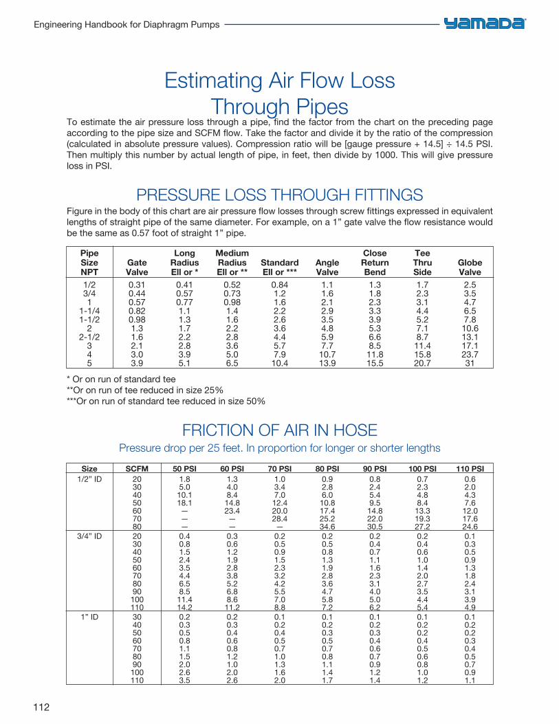
112
Engineering Handbook for Diaphragm Pumps
Estimating Air Flow Loss Through Pipes
To estimate the air pressure loss through a pipe, find the factor from the chart on the preceding page according to the pipe size and SCFM flow. Take the factor and divide it by the ratio of the compression (calculated in absolute pressure values). Compression ratio will be [gauge pressure + 14.5] ÷ 14.5 PSI. Then multiply this number by actual length of pipe, in feet, then divide by 1000. This will give pressure loss in PSI.
PRESSURE LOSS THROUGH FITTINGSFigure in the body of this chart are air pressure flow losses through screw fittings expressed in equivalent lengths of straight pipe of the same diameter. For example, on a 1” gate valve the flow resistance would be the same as 0.57 foot of straight 1” pipe.
* Or on run of standard tee**Or on run of tee reduced in size 25%***Or on run of standard tee reduced in size 50%
FRICTION OF AIR IN HOSEPressure drop per 25 feet. In proportion for longer or shorter lengths
PipeSizeNPT1/23/41
1-1/41-1/2
22-1/2
345
GateValve0.310.440.570.820.981.31.62.13.03.9
LongRadiusEll or *
0.410.570.771.11.31.72.22.83.95.1
MediumRadiusEll or **
0.520.730.981.41.62.22.83.65.06.5
StandardEll or ***
0.841.21.62.22.63.64.45.77.910.4
AngleValve
1.11.62.12.93.54.85.97.710.713.9
CloseReturnBend1.31.82.33.33.95.36.68.511.815.5
TeeThruSide1.72.33.14.45.27.18.711.415.820.7
GlobeValve
2.53.54.76.57.810.613.117.123.731
Size1/2” ID
3/4” ID
1” ID
SCFM20304050607080203040506070809010011030405060708090100110
50 PSI1.85.010.118.1———0.40.81.52.43.54.46.58.511.414.20.20.30.50.81.11.52.02.63.5
60 PSI1.34.08.414.823.4——0.30.61.21.92.83.85.26.88.611.20.20.30.40.60.81.21.02.02.6
70 PSI1.03.47.0
12.420.028.4—0.20.50.91.52.33.24.25.57.08.80.10.20.40.50.71.01.31.62.0
80 PSI0.92.86.0
10.817.425.234.60.20.50.81.31.92.83.64.75.87.20.10.20.30.50.70.81.11.41.7
90 PSI0.82.45.49.5
14.822.030.50.20.40.71.11.62.33.14.05.06.20.10.20.30.40.60.70.91.21.4
100 PSI0.72.34.88.4
13.319.327.20.20.40.61.01.42.02.73.54.45.40.10.20.20.40.50.60.81.01.2
110 PSI0.62.04.37.6
12.017.624.60.10.30.50.91.31.82.43.13.94.90.10.20.20.30.40.50.70.91.1
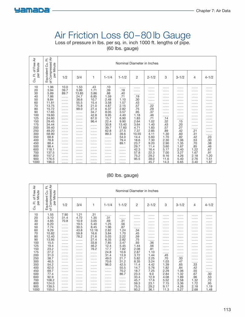
113
Chapter 7: Air Data
Air Friction Loss 60–80 lb GaugeLoss of pressure in lbs. per sq. in. inch 1000 ft. lengths of pipe.
(60 lbs. gauge)
1020304050607080901001251501752002503003504004505006007008009001000
1.963.945.897.869.8411.8113.7515.7217.6519.6024.6029.4534.4439.4049.2058.9068.878.888.498.4118.1137.5157.2176.5196.0
10.039.789.7……………………………………………………………………………………………………………………
1.535.9913.8524.738.655.575.899.0…………………………………………………………………………………………
.431.713.866.8510.715.421.027.434.742.867.096.4……………………………………………………………………
.10
.39
.881.592.483.584.876.378.059.9515.722.430.839.762.889.3………………………………………………
…….18.40.711.101.572.152.823.574.406.909.90
13.4017.6027.539.654.079.489.1………………………………
……………….19.30.43.57.75.95
1.181.832.643.644.717.37
10.5514.418.623.729.742.357.875.295.5……
……………………………….22.29.37.46.71
1.021.401.832.854.115.607.309.2011.416.422.329.239.045.7
…………………………………………………….14.32.43.57.89
1.301.702.302.903.605.177.009.1611.614.3
………………………………………………………….15.20.27.42.60.82
1.061.351.672.403.274.265.406.65
………………………………………………………………………….21.31.42.53.70.85
1.221.672.182.763.40
…………………………………………………………………………………….23.30.38.46.67.911.201.511.87
Cu.
Ft.
of F
ree
Air
per M
inut
e
Equi
vale
nt C
u. F
t.of
Com
pres
sed
Air
per M
inut
e Nominal Diameter in Inches
1/2 3/4 1 1-1/4 1-1/2 2 2-1/2 3 3-1/2 4 4-1/2
1020304050607080901001251501752002503003504004505006007008009001000
1.553.104.656.207.749.2910.8212.4013.9515.519.423.227.231.038.746.554.262.069.777.492.9108.2124.0139.5155.0
7.9031.470.8……………………………………………………………………………………………………………………
1.214.7210.919.530.543.859.878.2…………………………………………………………………………………………
.311.353.055.408.4512.1616.621.627.433.846.276.2……………………………………………………………………
…….31.69
1.251.962.823.845.036.357.8512.417.724.831.449.070.696.0…………………………………………
………….31.56.871.241.702.222.823.475.457.8210.613.921.731.242.555.570.286.7…………………………
………………………….34.45.59.75.93
1.442.082.873.725.828.3511.414.718.723.333.445.759.375.593.2
……………………………………………….36.56.81
1.101.442.253.244.425.767.259.0
12.917.623.129.236.1
…………………………………………………………………….45.70
1.031.391.822.292.844.085.527.159.1711.3
………………………………………………………………………….33.47.65.84
1.061.321.892.583.364.265.27
…………………………………………………………………………………….33.42.55.67.96
1.321.722.182.68
…………………………………………………………………………………………………….30.53.72.951.191.48
Cu.
Ft.
of F
ree
Air
per M
inut
e
Equi
vale
nt C
u. F
t.of
Com
pres
sed
Air
per M
inut
e Nominal Diameter in Inches
1/2 3/4 1 1-1/4 1-1/2 2 2-1/2 3 3-1/2 4 4-1/2
(80 lbs. gauge)
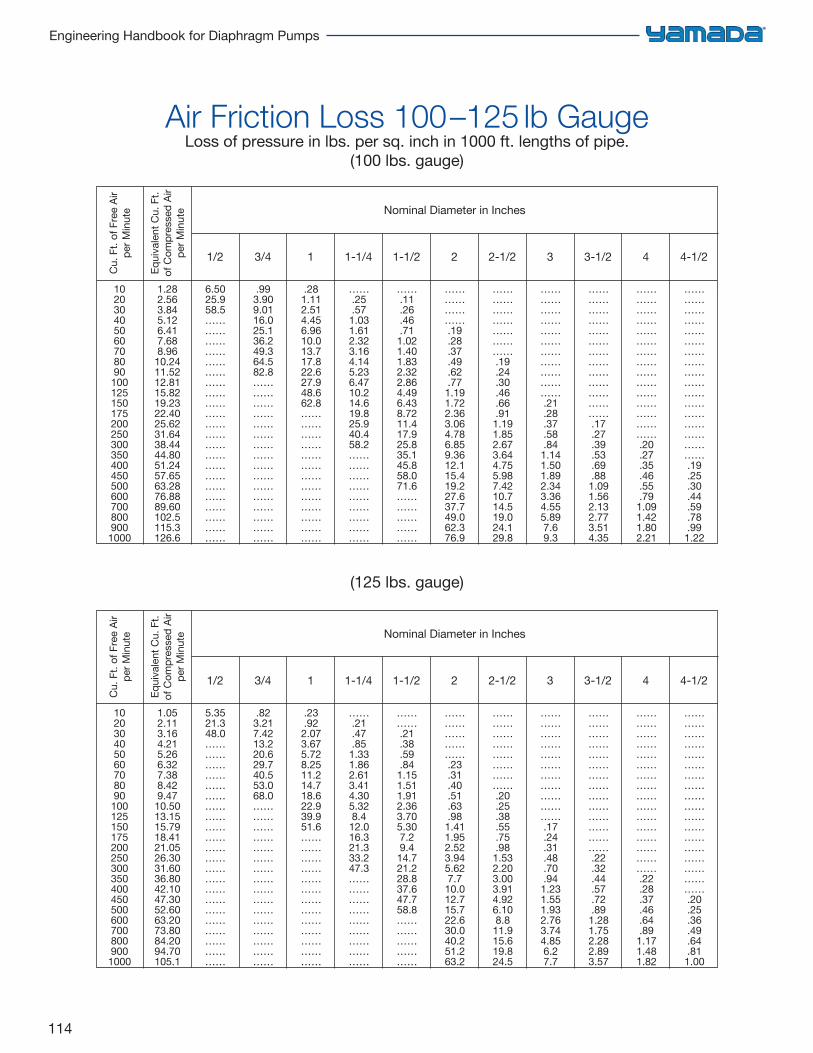
114
Engineering Handbook for Diaphragm Pumps
Air Friction Loss 100–125 lb GaugeLoss of pressure in lbs. per sq. inch in 1000 ft. lengths of pipe.
(100 lbs. gauge)
1020304050607080901001251501752002503003504004505006007008009001000
1.282.563.845.126.417.688.9610.2411.5212.8115.8219.2322.4025.6231.6438.4444.8051.2457.6563.2876.8889.60102.5115.3126.6
6.5025.958.5……………………………………………………………………………………………………………………
.993.909.0116.025.136.249.364.582.8……………………………………………………………………………………
.281.112.514.456.9610.013.717.822.627.948.662.8……………………………………………………………………
…….25.57
1.031.612.323.164.145.236.4710.214.619.825.940.458.2………………………………………………
…….11.26.46.711.021.401.832.322.864.496.438.7211.417.925.835.145.858.071.6…………………………
…………………….19.28.37.49.62.77
1.191.722.363.064.786.859.3612.115.419.227.637.749.062.376.9
…………………………………….19.24.30.46.66.91
1.191.852.673.644.755.987.4210.714.519.024.129.8
………………………………………………………….21.28.37.58.84
1.141.501.892.343.364.555.897.69.3
…………………………………………………………………….17.27.39.53.69.88
1.091.562.132.773.514.35
……………………………………………………………………………….20.27.35.46.55.79
1.091.421.802.21
………………………………………………………………………………………….19.25.30.44.59.78.991.22
Cu.
Ft.
of F
ree
Air
per M
inut
e
Equi
vale
nt C
u. F
t.of
Com
pres
sed
Air
per M
inut
e Nominal Diameter in Inches
1/2 3/4 1 1-1/4 1-1/2 2 2-1/2 3 3-1/2 4 4-1/2
1020304050607080901001251501752002503003504004505006007008009001000
1.052.113.164.215.266.327.388.429.4710.5013.1515.7918.4121.0526.3031.6036.8042.1047.3052.6063.2073.8084.2094.70105.1
5.3521.348.0……………………………………………………………………………………………………………………
.823.217.4213.220.629.740.553.068.0……………………………………………………………………………………
.23
.922.073.675.728.2511.214.718.622.939.951.6……………………………………………………………………
…….21.47.85
1.331.862.613.414.305.328.4
12.016.321.333.247.3………………………………………………
………….21.38.59.841.151.511.912.363.705.307.29.414.721.228.837.647.758.8…………………………
………………………….23.31.40.51.63.98
1.411.952.523.945.627.7
10.012.715.722.630.040.251.263.2
………………………………………….20.25.38.55.75.98
1.532.203.003.914.926.108.8
11.915.619.824.5
………………………………………………………….17.24.31.48.70.94
1.231.551.932.763.744.856.27.7
………………………………………………………………………….22.32.44.57.72.89
1.281.752.282.893.57
…………………………………………………………………………………….22.28.37.46.64.89
1.171.481.82
……………………………………………………………………………………………….20.25.36.49.64.811.00
Cu.
Ft.
of F
ree
Air
per M
inut
e
Equi
vale
nt C
u. F
t.of
Com
pres
sed
Air
per M
inut
e Nominal Diameter in Inches
1/2 3/4 1 1-1/4 1-1/2 2 2-1/2 3 3-1/2 4 4-1/2
(125 lbs. gauge)
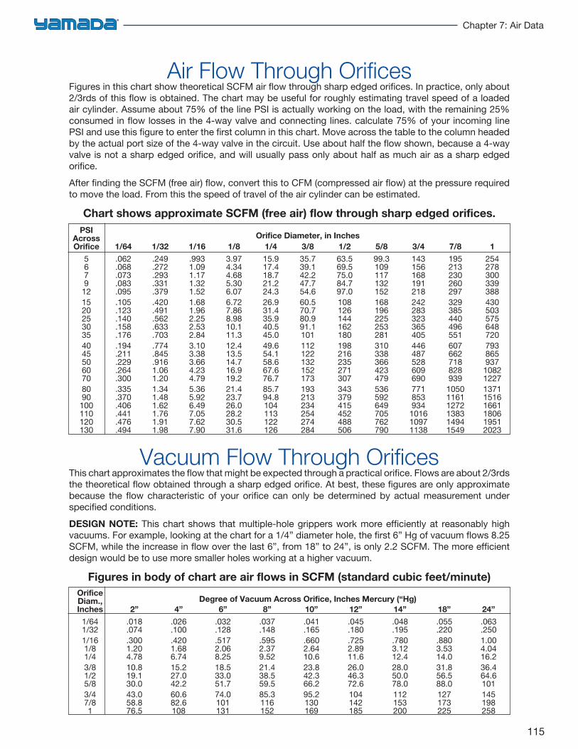
115
Chapter 7: Air Data
Air Flow Through OrificesFigures in this chart show theoretical SCFM air flow through sharp edged orifices. In practice, only about 2/3rds of this flow is obtained. The chart may be useful for roughly estimating travel speed of a loaded air cylinder. Assume about 75% of the line PSI is actually working on the load, with the remaining 25% consumed in flow losses in the 4-way valve and connecting lines. calculate 75% of your incoming line PSI and use this figure to enter the first column in this chart. Move across the table to the column headed by the actual port size of the 4-way valve in the circuit. Use about half the flow shown, because a 4-way valve is not a sharp edged orifice, and will usually pass only about half as much air as a sharp edged orifice.After finding the SCFM (free air) flow, convert this to CFM (compressed air flow) at the pressure required to move the load. From this the speed of travel of the air cylinder can be estimated.
Chart shows approximate SCFM (free air) flow through sharp edged orifices.
Vacuum Flow Through OrificesThis chart approximates the flow that might be expected through a practical orifice. Flows are about 2/3rds the theoretical flow obtained through a sharp edged orifice. At best, these figures are only approximate because the flow characteristic of your orifice can only be determined by actual measurement under specified conditions.DESIGN NOTE: This chart shows that multiple-hole grippers work more efficiently at reasonably high vacuums. For example, looking at the chart for a 1/4” diameter hole, the first 6” Hg of vacuum flows 8.25 SCFM, while the increase in flow over the last 6”, from 18” to 24”, is only 2.2 SCFM. The more efficient design would be to use more smaller holes working at a higher vacuum.
Figures in body of chart are air flows in SCFM (standard cubic feet/minute)
PSIAcrossOrifice
5679
12152025303540455060708090
100110120130
1/64
.062
.068
.073
.083
.095
.105
.123
.140
.158
.176
.194
.211
.229
.264
.300
.335
.370
.406
.441
.476
.494
1/32
.249
.272
.293
.331
.379
.420
.491
.562
.633
.703
.774
.845
.9161.061.201.341.481.621.761.911.98
1/16
.9931.091.171.321.521.681.962.252.532.843.103.383.664.234.795.365.926.497.057.627.90
1/8
3.974.344.685.306.076.727.868.9810.111.312.413.514.716.919.221.423.726.028.230.531.6
1/4
15.917.418.721.224.326.931.435.940.545.049.654.158.667.676.785.794.8104113122126
3/8
35.739.142.247.754.660.570.780.991.1101112122132152173193213234254274284
1/2
63.569.575.084.797.0108126144162180198216235271307343379415452488506
5/8
99.3109117132152168196225253281310338366423479536592649705762790
3/4
143156168191218242283323365405446487528609690771853934101610971138
7/8
195213230260297329385440496551607662718828939105011611272138314941549
1
25427830033938843050357564872079386593710821227137115161661180619512023
Orifice Diameter, in Inches
OrificeDiam.,Inches
1/641/321/161/81/43/81/25/83/47/81
2”
.018
.074
.3001.204.7810.819.130.043.058.876.5
4”
.026
.100
.4201.686.7415.227.042.260.682.6108
6”
.032
.128
.5172.068.2518.533.051.774.0101131
8”
.037
.148
.5952.379.5221.438.559.585.3116152
10”
.041
.165
.6602.6410.623.842.366.295.2130169
12”
.045
.180
.7252.8911.626.046.372.6104142185
14”
.048
.195
.7803.1212.428.050.078.0112153200
18”
.055
.220
.8803.5314.031.856.588.0127173225
24”
.063
.2501.004.0416.236.464.6101145198258
Degree of Vacuum Across Orifice, Inches Mercury (“Hg)
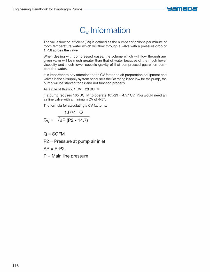
116
Engineering Handbook for Diaphragm Pumps
CV InformationThe value flow co-efficient (CV) is defined as the number of gallons per minute of room temperature water which will flow through a valve with a pressure drop of 1 PSI across the valve.When dealing with compressed gases, the volume which will flow through any given valve will be much greater than that of water because of the much lower viscosity and much lower specific gravity of that compressed gas when com-pared to water.It is important to pay attention to the CV factor on air preparation equipment and valves in the air supply system because if the CV rating is too low for the pump, the pump will be starved for air and not function properly.As a rule of thumb, 1 CV = 23 SCFM.If a pump requires 105 SCFM to operate 105/23 = 4.57 CV. You would need an air line valve with a minimum CV of 4-57.The formula for calculating a CV factor is:
CV =
Q = SCFMP2 = Pressure at pump air inlet∆P = P-P2P = Main line pressure
1.024 ˘ QP (P2 - 14.7)
117
Chapter 8: Principles of Operation
Principles of Operation
Diaphragm Pump Fundamentals 118
Check Valve Types 118
Pulsation Dampeners 120
Pulsation Dampeners–Manual 121
Pulsation Dampeners–Automatic 122
Air Pressure Regulators 123
118
Engineering Handbook for Diaphragm Pumps
BALL TYPE CHECK VALVE
• This is the most common type of check valve,made from a wide variety of material includingsuch materials as all common elastomers, PTFEand stainless steel
• Good for high viscosity materials• Good for high concentrations of solids but limited on
solids size• Available in almost all size pumps
There are two diaphragms fixed to the center rod, one at each end. When compressed air is supplied to air chamber B (right side, see Fig. 1.1), the center rod moves to the right, the material in liquid chamber B is pushed out, and at the same material is drawn into liquid chamber A. When the center rod is moved full-stroke to the right, the air switch valve is switched, compressed air is sent to air chamber A (left side, see Fig. 1.2), and the center rod moves to the left. The material in liquid chamber A is pushed out, and at the same time material is drawn into liquid chamber
B. The reciprocating motion of the diaphragms along with the action of the check valves placed at the inlet and outlet of each liquid chamber enable the pump to move liquid in a continuous flow.There are virtually no diaphragm pumps made that do not use check valves to direct the flow of liquid through the pump. There are several common types of check valves, each with it’s own unique design for a specific type of application.
Check Valve Types
Diaphragm Pump Fundamentals
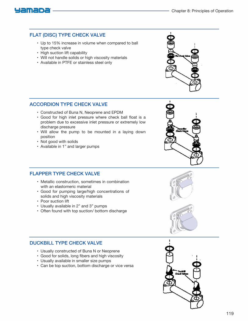
119
Chapter 8: Principles of Operation
FLAT (DISC) TYPE CHECK VALVE
• Up to 15% increase in volume when compared to balltype check valve
• High suction lift capability• Will not handle solids or high viscosity materials• Available in PTFE or stainless steel only
ACCORDION TYPE CHECK VALVE
• Constructed of Buna N, Neoprene and EPDM• Good for high inlet pressure where check ball float is a
problem due to excessive inlet pressure or extremely lowdischarge pressure
• Will allow the pump to be mounted in a laying downposition
• Not good with solids• Available in 1” and larger pumps
FLAPPER TYPE CHECK VALVE
• Metallic construction, sometimes in combinationwith an elastomeric material
• Good for pumping large/high concentrations ofsolids and high viscosity materials
• Poor suction lift• Usually available in 2” and 3” pumps• Often found with top suction/ bottom discharge
DUCKBILL TYPE CHECK VALVE
• Usually constructed of Buna N or Neoprene• Good for solids, long fibers and high viscosity• Usually available in smaller size pumps• Can be top suction, bottom discharge or vice versa
120
Engineering Handbook for Diaphragm Pumps
Pulsation DampenersManual vs. Automatic Type
ManualThis model is designed for use on constant pressure systems and allows the user to fine-tune the dampener by adjusting the air pressure into the unit manually. For proper system dampening regulation, the supply air pressure requires a 10–20% lower differential pressure than the system liquid pressure going into the dampener. The self-relieving regulator will maintain approximately 90% of the system liquid pressure.
AutomaticThis model is designed for varying system pressures, for example, a filter press application where the pressure continuously builds and than reverts back to the original pressure. A constant air supply is required to automatically compensate for additional higher pressures when required. The air supply pressure must be higher than the maximum system liquid pressure for the automatic dampener to operate within the liquid systems range.
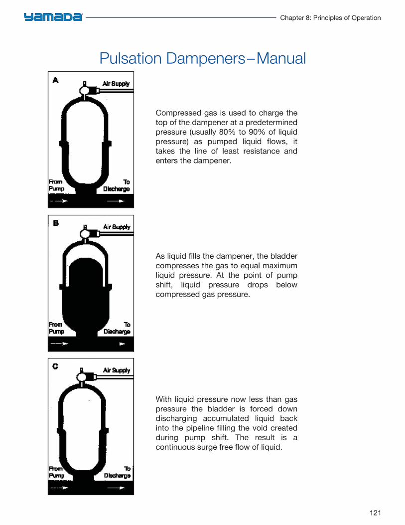
121
Chapter 8: Principles of Operation
Compressed gas is used to charge the top of the dampener at a predetermined pressure (usually 80% to 90% of liquid pressure) as pumped liquid flows, it takes the line of least resistance and enters the dampener.
As liquid fills the dampener, the bladder compresses the gas to equal maximum liquid pressure. At the point of pump shift, liquid pressure drops below compressed gas pressure.
With liquid pressure now less than gas pressure the bladder is forced down discharging accumulated liquid back into the pipeline filling the void created during pump shift. The result is a continuous surge free flow of liquid.
Pulsation Dampeners–Manual
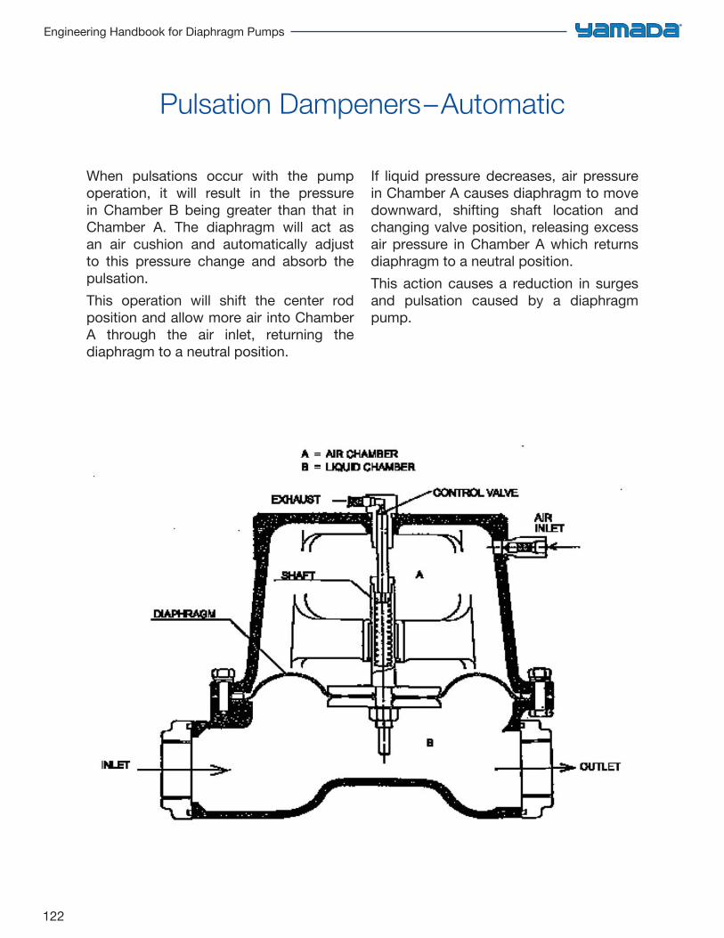
122
Engineering Handbook for Diaphragm Pumps
Pulsation Dampeners–Automatic
When pulsations occur with the pump operation, it will result in the pressure in Chamber B being greater than that in Chamber A. The diaphragm will act as an air cushion and automatically adjust to this pressure change and absorb the pulsation. This operation will shift the center rod position and allow more air into Chamber A through the air inlet, returning the diaphragm to a neutral position.
If liquid pressure decreases, air pressure in Chamber A causes diaphragm to move downward, shifting shaft location and changing valve position, releasing excess air pressure in Chamber A which returns diaphragm to a neutral position.This action causes a reduction in surges and pulsation caused by a diaphragm pump.
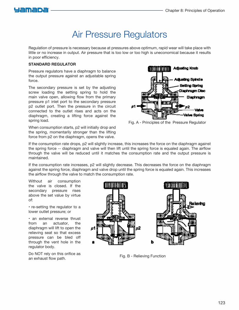
123
Chapter 8: Principles of Operation
Air Pressure RegulatorsRegulation of pressure is necessary because at pressures above optimum, rapid wear will take place with little or no increase in output. Air pressure that is too low or too high is uneconomical because it results in poor efficiency.STANDARD REGULATOR
Pressure regulators have a diaphragm to balance the output pressure against an adjustable spring force.The secondary pressure is set by the adjusting screw loading the setting spring to hold the main valve open, allowing flow from the primary pressure p1 inlet port to the secondary pressure p2 outlet port. Then the pressure in the circuit connected to the outlet rises and acts on the diaphragm, creating a lifting force against the spring load.When consumption starts, p2 will initially drop and the spring, momentarily stronger than the lifting force from p2 on the diaphragm, opens the valve.If the consumption rate drops, p2 will slightly increase, this increases the force on the diaphragm against the spring force -- diaphragm and valve will then lift until the spring force is equaled again. The airflow through the valve will be reduced until it matches the consumption rate and the output pressure is maintained.If the consumption rate increases, p2 will slightly decrease. This decreases the force on the diaphragm against the spring force, diaphragm and valve drop until the spring force is equaled again. This increases the airflow through the valve to match the consumption rate.Without air consumption the valve is closed. If the secondary pressure rises above the set value by virtue of:• re-setting the regulator to alower outlet pressure; or• an external reverse thrustfrom an actuator, the diaphragm will lift to open the relieving seat so that excess pressure can be bled off through the vent hole in the regulator body.Do NOT rely on this orifice as an exhaust flow path.
Fig. A - Principles of the Pressure Regulator
Fig. B - Relieving Function
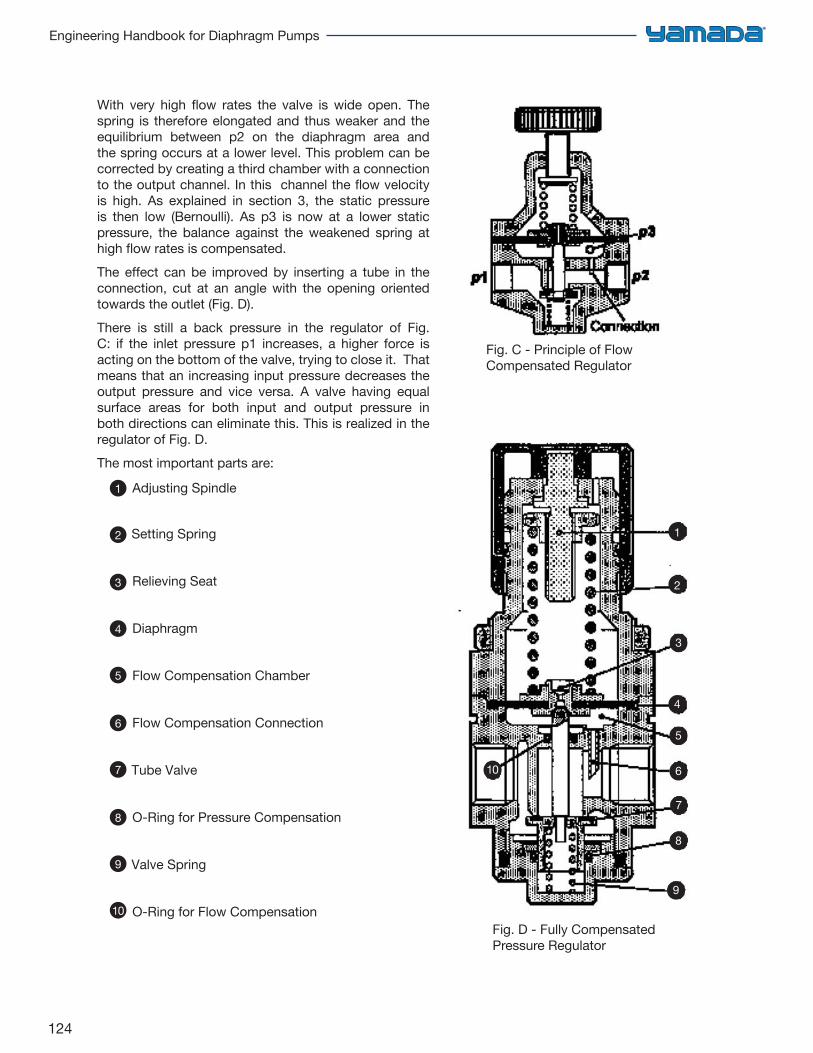
124
Engineering Handbook for Diaphragm Pumps
With very high flow rates the valve is wide open. The spring is therefore elongated and thus weaker and the equilibrium between p2 on the diaphragm area and the spring occurs at a lower level. This problem can be corrected by creating a third chamber with a connection to the output channel. In this channel the flow velocity is high. As explained in section 3, the static pressure is then low (Bernoulli). As p3 is now at a lower static pressure, the balance against the weakened spring at high flow rates is compensated.The effect can be improved by inserting a tube in the connection, cut at an angle with the opening oriented towards the outlet (Fig. D).There is still a back pressure in the regulator of Fig. C: if the inlet pressure p1 increases, a higher force is acting on the bottom of the valve, trying to close it. That means that an increasing input pressure decreases the output pressure and vice versa. A valve having equal surface areas for both input and output pressure in both directions can eliminate this. This is realized in the regulator of Fig. D.The most important parts are:
Adjusting Spindle
Setting Spring
Relieving Seat
Diaphragm
Flow Compensation Chamber
Flow Compensation Connection
Tube Valve
O-Ring for Pressure Compensation
Valve Spring
O-Ring for Flow Compensation10
9
8
7
6
5
4
3
2
1
1
2
3
4
5
6
7
8
9
10
Fig. D - Fully Compensated Pressure Regulator
Fig. C - Principle of Flow Compensated Regulator
125
Chapter 9: Installation & Troubleshooting
Pipe Tightening, Flange Loading,& Discharge Piping Procedures 126
Pump Flange Connections 127
Suction Pipe Installation 128
Discharge Piping 129
Air Supply 130
Other Pump Operation Tips 131
Recommended Installation 132
Troubleshooting Guide 133
Acknowledgements 135
Installation & Troubleshooting
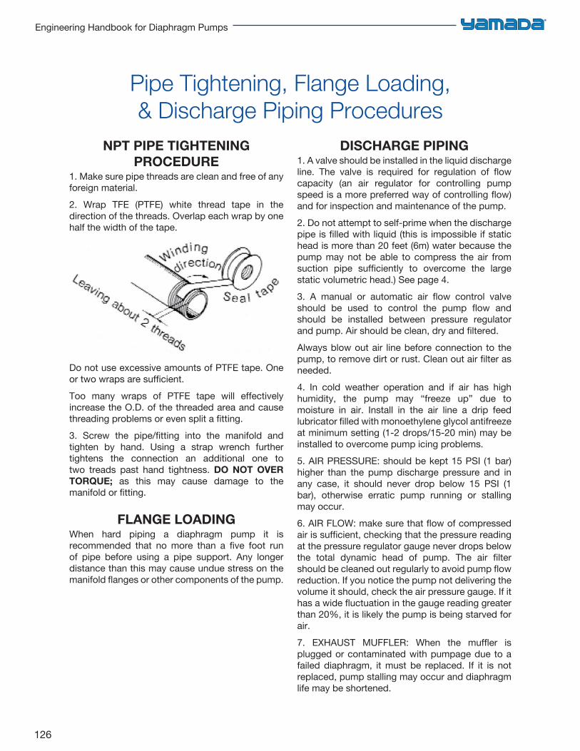
126
Engineering Handbook for Diaphragm Pumps
Pipe Tightening, Flange Loading,& Discharge Piping Procedures
NPT PIPE TIGHTENING PROCEDURE
1. Make sure pipe threads are clean and free of anyforeign material.2. Wrap TFE (PTFE) white thread tape in thedirection of the threads. Overlap each wrap by one half the width of the tape.
Do not use excessive amounts of PTFE tape. One or two wraps are sufficient.Too many wraps of PTFE tape will effectively increase the O.D. of the threaded area and cause threading problems or even split a fitting.3. Screw the pipe/fitting into the manifold andtighten by hand. Using a strap wrench further tightens the connection an additional one to two treads past hand tightness. DO NOT OVERTORQUE; as this may cause damage to the manifold or fitting.
FLANGE LOADINGWhen hard piping a diaphragm pump it is recommended that no more than a five foot run of pipe before using a pipe support. Any longer distance than this may cause undue stress on the manifold flanges or other components of the pump.
DISCHARGE PIPING1. A valve should be installed in the liquid dischargeline. The valve is required for regulation of flow capacity (an air regulator for controlling pump speed is a more preferred way of controlling flow) and for inspection and maintenance of the pump.2. Do not attempt to self-prime when the dischargepipe is filled with liquid (this is impossible if static head is more than 20 feet (6m) water because the pump may not be able to compress the air from suction pipe sufficiently to overcome the large static volumetric head.) See page 4.3. A manual or automatic air flow control valveshould be used to control the pump flow and should be installed between pressure regulator and pump. Air should be clean, dry and filtered.Always blow out air line before connection to the pump, to remove dirt or rust. Clean out air filter as needed.4. In cold weather operation and if air has highhumidity, the pump may “freeze up” due to moisture in air. Install in the air line a drip feed lubricator filled with monoethylene glycol antifreeze at minimum setting (1-2 drops/15-20 min) may be installed to overcome pump icing problems.5. AIR PRESSURE: should be kept 15 PSI (1 bar)higher than the pump discharge pressure and in any case, it should never drop below 15 PSI (1 bar), otherwise erratic pump running or stalling may occur.6. AIR FLOW: make sure that flow of compressedair is sufficient, checking that the pressure reading at the pressure regulator gauge never drops below the total dynamic head of pump. The air filter should be cleaned out regularly to avoid pump flow reduction. If you notice the pump not delivering the volume it should, check the air pressure gauge. If it has a wide fluctuation in the gauge reading greater than 20%, it is likely the pump is being starved for air.7. EXHAUST MUFFLER: When the muffler isplugged or contaminated with pumpage due to a failed diaphragm, it must be replaced. If it is not replaced, pump stalling may occur and diaphragm life may be shortened.
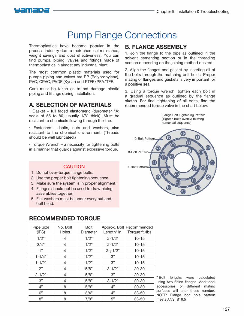
127
Chapter 9: Installation & Troubleshooting
Pump Flange ConnectionsThermoplastics have become popular in the process industry due to their chemical resistance, weight savings and cost effectiveness. You can find pumps, piping, valves and fittings made of thermoplastics in almost any industrial plant.The most common plastic materials used for pumps piping and valves are PP (Polypropylene), PVC, CPVC, PVDF (Kynar) and PTFE/PFA/TFE.Care must be taken as to not damage plastic piping and fittings during installation.
A. SELECTION OF MATERIALS• Gasket – full faced elastomeric (durometer “A:scale of 55 to 80, usually 1/8” thick). Must be resistant to chemicals flowing through the line.• Fasteners – bolts, nuts and washers, alsoresistant to the chemical environment. (Threads should be well lubricated.)• Torque Wrench – a necessity for tightening boltsin a manner that guards against excessive torque.
B. FLANGE ASSEMBLY1. Join the flange to the pipe as outlined in thesolvent cementing section or in the threading section depending on the joining method desired.2. Align the flanges and gasket by inserting all ofthe bolts through the matching bolt holes. Proper mating of flanges and gaskets is very important for a positive seal.3. Using a torque wrench, tighten each bolt ina gradual sequence as outlined by the flange sketch. For final tightening of all bolts, find the recommended torque valve in the chart below.
Pipe Size (IPS)
No. BoltHoles
BoltDiameter
Approx. Bolt Length* in.
RecommendedTorque ft./lbs
1/2” 4 1/2” 2-1/2” 10-153/4” 4 1/2” 2-1/2” 10-151” 4 1/2” 2ң-1/2” 10-15
1-1/4” 4 1/2” 3” 10-151-1/2” 4 1/2” 3” 10-15
2” 4 5/8” 3-1/2” 20-302-1/2” 4 5/8” 3” 20-30
3” 4 5/8” 3-1/2” 20-304” 8 5/8” 4” 20-306” 8 3/4” 4” 33-508” 8 7/8” 5” 33-50
CAUTION1. Do not over-torque flange bolts.2. Use the proper bolt tightening sequence.3. Make sure the system is in proper alignment.4. Flanges should not be used to draw piping
assemblies together.5. Flat washers must be under every nut and
bolt head.
RECOMMENDED TORQUE
* Bolt lengths were calculatedusing two Eslon flanges. Additional accessories or different mating surfaces will alter these number. NOTE: Flange bolt hole pattern meets ANSI B16.5
Flange Bolt Tightening Pattern(Tighten bolts evenly; follwing numerical sequence)
12-Bolt Pattern
8-Bolt Pattern
4-Bolt Pattern
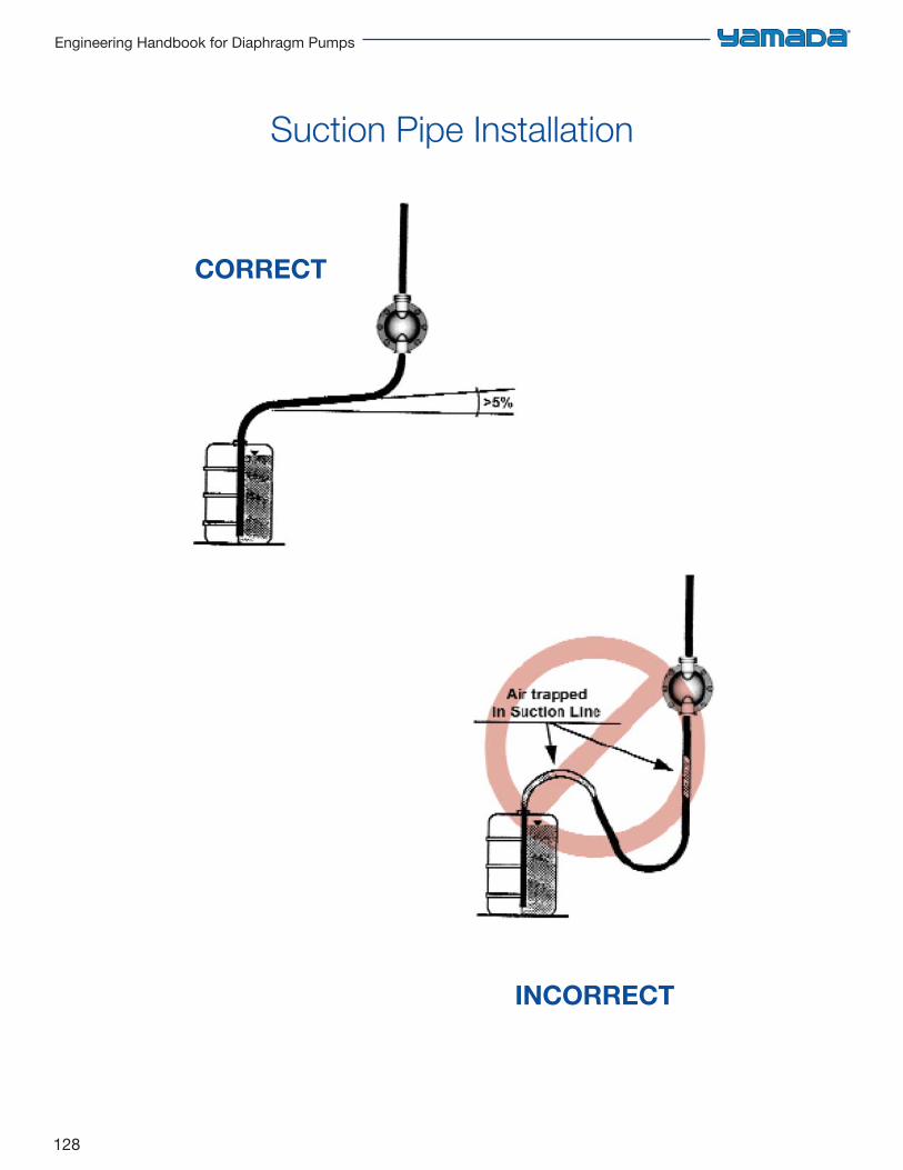
128
Engineering Handbook for Diaphragm Pumps
Suction Pipe Installation
CORRECT
INCORRECT
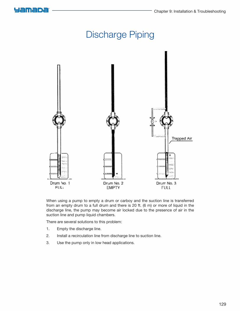
129
Chapter 9: Installation & Troubleshooting
When using a pump to empty a drum or carboy and the suction line is transferred from an empty drum to a full drum and there is 20 ft. (6 m) or more of liquid in the discharge line, the pump may become air locked due to the presence of air in the suction line and pump liquid chambers.There are several solutions to this problem:1. Empty the discharge line.2. Install a recirculation line from discharge line to suction line.3. Use the pump only in low head applications.
Discharge Piping
130
Engineering Handbook for Diaphragm Pumps
Air SupplyMake sure air supply is adequate to run the pump. The air should be clean and dry.- Air should be filtered with a 5 micron filter- Air should be dried to a dew point of -40°F to prevent unwanted pump icing.When possible, control the pump flow rate by controlling the air supply as opposed to controlling the flow rate by using a valve on this pump discharge.Controlling the air supply is the most efficient way to control an air operated pump since it requires less energy to overcome a lower discharge pressure, although a certain amount of discharge pressure is required to prevent the check valve balls from floating.It is highly recommended that a combination Filter/Regulator be installed with each pump.
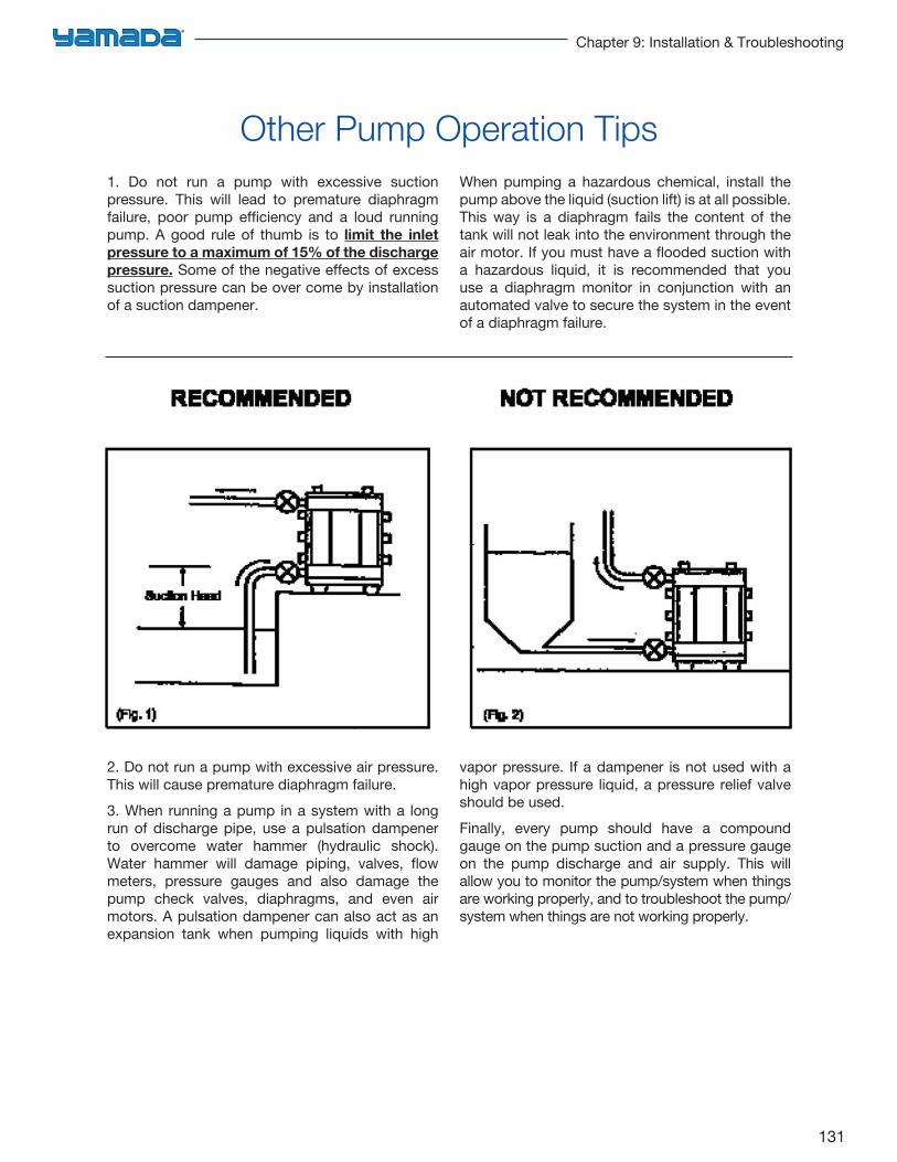
131
Chapter 9: Installation & Troubleshooting
2. Do not run a pump with excessive air pressure.This will cause premature diaphragm failure.3. When running a pump in a system with a longrun of discharge pipe, use a pulsation dampener to overcome water hammer (hydraulic shock). Water hammer will damage piping, valves, flow meters, pressure gauges and also damage the pump check valves, diaphragms, and even air motors. A pulsation dampener can also act as an expansion tank when pumping liquids with high
vapor pressure. If a dampener is not used with a high vapor pressure liquid, a pressure relief valve should be used. Finally, every pump should have a compound gauge on the pump suction and a pressure gauge on the pump discharge and air supply. This will allow you to monitor the pump/system when things are working properly, and to troubleshoot the pump/system when things are not working properly.
1. Do not run a pump with excessive suctionpressure. This will lead to premature diaphragm failure, poor pump efficiency and a loud running pump. A good rule of thumb is to limit the inletpressure to a maximum of 15% of the discharge pressure. Some of the negative effects of excess suction pressure can be over come by installation of a suction dampener.
When pumping a hazardous chemical, install the pump above the liquid (suction lift) is at all possible. This way is a diaphragm fails the content of the tank will not leak into the environment through the air motor. If you must have a flooded suction with a hazardous liquid, it is recommended that you use a diaphragm monitor in conjunction with an automated valve to secure the system in the event of a diaphragm failure.
Other Pump Operation Tips
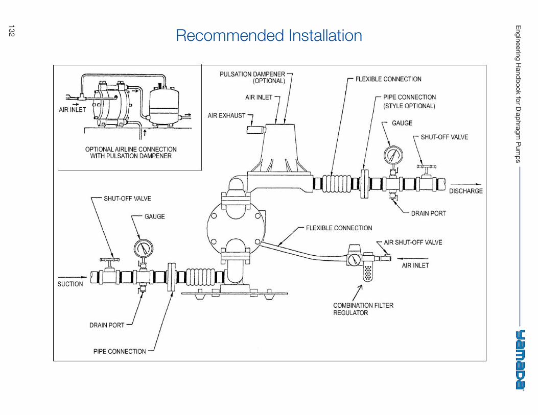
132
Engineering Handbook for Diaphragm
Pumps
Recommended Installation
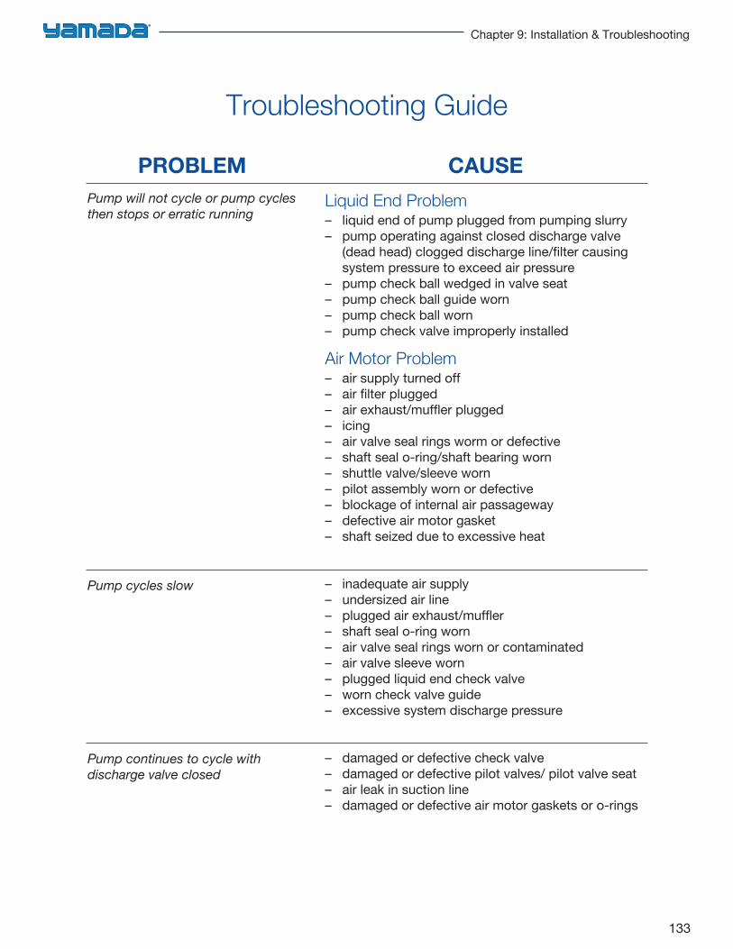
133
Chapter 9: Installation & Troubleshooting
Troubleshooting Guide
PROBLEMPump will not cycle or pump cycles then stops or erratic running
Pump cycles slow
Pump continues to cycle with discharge valve closed
Liquid End Problem– liquid end of pump plugged from pumping slurry– pump operating against closed discharge valve
(dead head) clogged discharge line/filter causingsystem pressure to exceed air pressure
– pump check ball wedged in valve seat– pump check ball guide worn– pump check ball worn– pump check valve improperly installed
Air Motor Problem– air supply turned off– air filter plugged– air exhaust/muffler plugged– icing– air valve seal rings worm or defective– shaft seal o-ring/shaft bearing worn– shuttle valve/sleeve worn– pilot assembly worn or defective– blockage of internal air passageway– defective air motor gasket– shaft seized due to excessive heat
– inadequate air supply– undersized air line– plugged air exhaust/muffler– shaft seal o-ring worn– air valve seal rings worn or contaminated– air valve sleeve worn– plugged liquid end check valve– worn check valve guide– excessive system discharge pressure
– damaged or defective check valve– damaged or defective pilot valves/ pilot valve seat– air leak in suction line– damaged or defective air motor gaskets or o-rings
CAUSE
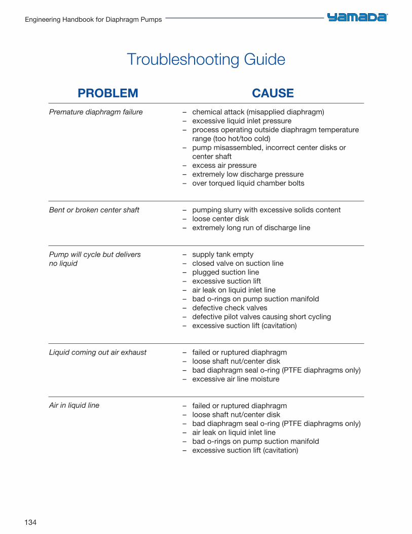
134
Engineering Handbook for Diaphragm Pumps
– chemical attack (misapplied diaphragm)– excessive liquid inlet pressure– process operating outside diaphragm temperature
range (too hot/too cold)– pump misassembled, incorrect center disks or
center shaft– excess air pressure– extremely low discharge pressure– over torqued liquid chamber bolts
– pumping slurry with excessive solids content– loose center disk– extremely long run of discharge line
– supply tank empty– closed valve on suction line– plugged suction line– excessive suction lift– air leak on liquid inlet line– bad o-rings on pump suction manifold– defective check valves– defective pilot valves causing short cycling– excessive suction lift (cavitation)
– failed or ruptured diaphragm– loose shaft nut/center disk– bad diaphragm seal o-ring (PTFE diaphragms only)– excessive air line moisture
– failed or ruptured diaphragm– loose shaft nut/center disk– bad diaphragm seal o-ring (PTFE diaphragms only)– air leak on liquid inlet line– bad o-rings on pump suction manifold– excessive suction lift (cavitation)
Troubleshooting Guide
PROBLEM CAUSEPremature diaphragm failure
Bent or broken center shaft
Pump will cycle but delivers no liquid
Liquid coming out air exhaust
Air in liquid line
135
Chapter 9: Installation & Troubleshooting
Acknowledgements
When compiling the Air-Powered Double Diaphragm Pump Engineering Handbook, we used data from various sources which include:
• Hydraulic Institute Engineering Data Book
• Cameron Hydraulic Data Book, Ingersoll Rand Co.
• Hydraulic Handbook, Fairbanks Morse Pump
• Basic Pneumatics Manual, SMC Pneumatics, Inc.
• Fluid Power Data Book, Hedland Division of Racine Federated, Inc.
• Compressed Air Pocket Guide, Domnick Hunter, Ltd.
• Chemical Resistance Guide, Compass Publications
• Blacoh Fluid Control Data Book
Yamada America, Inc.955 East Algonquin RoadArlington Heights, IL 60005800 990-7867 Toll-Free
847 631-9200 Phone847 631-9273 [email protected]: www.yamadapump.com
YOUR LOCAL DISTRIBUTOR:
Designed and printed in the U.S.A.
Form #EH0214