“yamabico” autonomous mobile robotsusers.cecs.anu.edu.au/~rsl/yamidoc1_5.pdf · “yamabico”...
TRANSCRIPT

“Yamabico” Autonomous Mobile Robots
User Programming GuideHardware & Software Implementation Notes
Reference
Version 1.5
Last modified 10/7/96

Yamabico Autonomous Mobile Robot Documentation 1
CONTENTS
1. Hardware................................................................................ 5
1.1 Architecture Overview.......................................................................................... 5
1.2 Modules ................................................................................................................. 6
1.2.1 68000 Master Module mm-KEI.................................................................... 61.2.1.1 CPU................................................................................................. 6
1.2.1.1.1 Reset Signal.................................................................................................. 61.2.1.2 Control............................................................................................. 71.2.1.3 PIA — Parallel Interface Adaptor..................................................... 71.2.1.4 Memory........................................................................................... 81.2.1.5 Reset................................................................................................ 81.2.1.6 ACIA — Asynchronous Communications Interface Adaptor............. 81.2.1.7 PTM/RTC/LED ............................................................................. 101.2.1.8 Bus Buffer...................................................................................... 111.2.1.9 Yamabico Bus II............................................................................ 111.2.1.10 Not on any diagram...................................................................... 11
1.2.2 Transputer Locomotion Module ................................................................. 111.2.2.1 Introduction ................................................................................... 111.2.2.2 MPU .............................................................................................. 121.2.2.3 Address Decoder............................................................................ 131.2.2.4 Memory......................................................................................... 131.2.2.5 Dual Port Memory (DPM).............................................................. 131.2.2.6 Yamabico Bus Interface................................................................. 141.2.2.7 PWM and Counter ......................................................................... 141.2.2.8 LED............................................................................................... 141.2.2.9 Second Floor Interface (2F-I/F)...................................................... 14
1.2.3 Ultrasonic Sensor Module........................................................................... 151.2.3.1 CPU............................................................................................... 151.2.3.2 Address Decoder............................................................................ 161.2.3.3 Memory......................................................................................... 161.2.3.4 DPM .............................................................................................. 161.2.3.5 PTM .............................................................................................. 161.2.3.6 ACIA ............................................................................................. 161.2.3.7 Transmit......................................................................................... 171.2.3.8 Receive.......................................................................................... 171.2.3.9 Connectors..................................................................................... 17
2. Software................................................................................ 19
2.1 Architecture Overview........................................................................................ 19
2.1.1 Directory Tree............................................................................................ 20
2.2 MOSRA............................................................................................................... 21
2.2.1 Features...................................................................................................... 21

Yamabico Autonomous Mobile Robot Documentation 2
2.2.2 MOSRA API.............................................................................................. 222.2.2.1 Memory Allocation......................................................................... 222.2.2.2 Memory Modules........................................................................... 232.2.2.3 Process Control.............................................................................. 272.2.2.4 Interprocess Communication (IPC)................................................. 322.2.2.5 Interrupt & Exception Handling...................................................... 352.2.2.6 Semaphores.................................................................................... 38
2.2.3 MOSRA Implementation............................................................................ 422.2.3.1 System Initialisation & the Global System Table............................. 422.2.3.2 Memory Allocation......................................................................... 432.2.3.3 Memory Modules........................................................................... 432.2.3.4 Process........................................................................................... 452.2.3.5 Messages........................................................................................ 462.2.3.6 Interrupts & Exceptions ................................................................. 472.2.3.7 System Calls & Register Usage....................................................... 47
2.2.4 The MOSRA directory............................................................................... 49
2.3 Function Modules ............................................................................................... 50
2.3.1 Ultrasonic sensor module............................................................................ 502.3.1.1 API ................................................................................................ 502.3.1.2 Implementation............................................................................... 512.3.1.3 Directory........................................................................................ 52
2.3.2 ISeye Software United Environment (ISSUE)............................................. 532.3.2.1 Directory........................................................................................ 53
2.3.3 Spur (Locomotion module)......................................................................... 542.3.3.1 API ................................................................................................ 552.3.3.2 Implementation............................................................................... 652.3.3.3 Directory........................................................................................ 69
2.3.4 Voice generator module.............................................................................. 702.3.4.1 API ................................................................................................ 702.3.4.2 Implementation............................................................................... 742.3.4.3 Directory........................................................................................ 75
2.3.5 Timer functions.......................................................................................... 762.3.5.1 API ................................................................................................ 762.3.5.2 Implementation............................................................................... 77
2.3.6 Whisker functions....................................................................................... 782.3.6.1 API ................................................................................................ 782.3.6.2 Implementation............................................................................... 82
2.3.7 ROMANCE & RADNET console functions............................................... 832.3.7.1 ROMANCE API ............................................................................ 832.3.7.2 RADNET Console API .................................................................. 842.3.7.3 ROMANCE Implementation.......................................................... 852.3.7.4 Directory........................................................................................ 86
2.4 Networking.......................................................................................................... 87
2.4.1 Architecture................................................................................................ 87
2.4.2 Network User Utility Programs.................................................................. 88

Yamabico Autonomous Mobile Robot Documentation 3
2.4.2.1 Remote .......................................................................................... 892.4.2.2 Radcon (RADNET Console) .......................................................... 902.4.2.3 DLoad............................................................................................ 90
2.4.3 The RADNET link server........................................................................... 90
2.4.4 Client API - Robot side............................................................................... 91
2.4.5 Client API - UNIX side.............................................................................. 982.4.5.1 Communication.............................................................................. 982.4.5.2 NetShell........................................................................................103
2.5 Inter-module Communication and the Yamabico Bus.....................................110
2.5.1 Case study - The Locomotion Module .......................................................112
2.6 Software Development.......................................................................................116
2.6.1 User program development........................................................................1162.6.1.1 Compilation...................................................................................116
2.6.1.1.1 Example programs.................................................................................... 1172.6.1.1.2 Robocc & mcc........................................................................................... 117
2.6.1.2 Romance.......................................................................................1172.6.1.3 Simulation.....................................................................................118
2.6.1.3.1 AMROS.................................................................................................... 1182.6.1.3.2 Marvin...................................................................................................... 119
2.6.1.4 Tools.............................................................................................1202.6.1.4.1 Robocon.................................................................................................... 1202.6.1.4.2 Roboemon................................................................................................. 1202.6.1.4.3 Robotra..................................................................................................... 120
2.6.1.5 Environment..................................................................................120
2.6.2 Building the Yamabico software................................................................1212.6.2.1 Compiling the MOSRA Kernel......................................................1212.6.2.2 Making a Master Module ROM image...........................................1212.6.2.3 Compiling function module code...................................................1222.6.2.4 Changing robot library code..........................................................122
2.7 Implementation of a Robot Simulator...............................................................124
2.7.1 Overview of Yamabico architecture...........................................................124
2.7.2 AMROS Implementation...........................................................................1252.7.2.1 Implementation of user calls..........................................................126
2.7.2.1.1 The UltraSonic module API calls .............................................................. 1272.7.2.1.2 The Locomotion module Spur API calls.................................................... 127
2.7.3 Marvin Implementation..............................................................................1292.7.3.1 Implementation of user calls..........................................................129
2.7.3.1.1 The UltraSonic module API calls .............................................................. 1302.7.3.1.2 The Locomotion module Spur API calls.................................................... 130
2.7.3.2 Marvin multi-robot synchronisation scheme...................................132
3. Appendices.......................................................................... 135
3.1 Appendix A - API Prototype Reference............................................................135
3.1.1 MOSRA....................................................................................................135
3.1.2 Miscellaneous............................................................................................136

Yamabico Autonomous Mobile Robot Documentation 4
3.1.3 Function Modules......................................................................................136
3.2 Appendix B - AMROS Map file format ............................................................139
3.3 Additional Information......................................................................................139
3.3.1 Contacts ....................................................................................................139
3.3.2 World Wide Web (WWW).........................................................................139
3.4 Bibliography.......................................................................................................140
3.5 Document History ..............................................................................................141

Yamabico Autonomous Mobile Robot Documentation 5
1. Hardware
The Yamabico robot is designed primarily for research and experimentation. Therefore, the
software and hardware details are available to the user, for modification and revision at any time
as required to suit the current purpose. With this in mind, the robot has been designed so as to
simplify development, at the expense of power conservation, size, and overall cost.
The standard body of the robot is designed to be small to allow experimentation in a
crowded laboratory, and to make handling easier. The purpose of the small robot is for the
investigation and validation of navigational and sensing strategies. Hence, it uses wheels, and is
designed for an indoor environment. This greatly simplifies research.
It is intended that the Hardware section of this document be read in conjunction with the
circuit diagrams and the manufacturers data sheets for each individual IC. This information is
gathered together into the Yamabico Hardware Manual [Yam95], a mix of English and Japanese
documentation.
The aim of this documentation is to provide an understanding of how the hardware is
designed to be used. Further information for programming can be found by inspection of the data
sheets.
1.1 Architecture Overview
The robot’s architecture is broken down into functional modules, according to function, to
simplify research and development on individual components. For example, there is one module
to control the ultrasonic sensing, and another module to control the motor drive system. All
decision making is centralised, and is executed on a master module which is in control of the
entire system. This is the behaviour level. This simplifies the process of upgrading and
modifying individual function modules, because their operation and interactions are very clearly
defined.

Yamabico Autonomous Mobile Robot Documentation 6
1.2 Modules
1.2.1 68000 Master Module mm-KEI
The following descriptions are arranged according to which sheet of the circuit diagram
they appear on.
1.2.1.1 CPU
The CPU is a 10MHz 68000, using a 16 bit data bus and a 24 bit address bus.
1.2.1.1.1 Reset Signal
The reset signal is activated by several sources:
• The reset switch, SW1
• Power-on reset circuit
• Power low condition, monitored by a MAX695
• Yamabico Bus reset line
serial port 1 (Romance)
serial port 2
parallel port 1
parallel port 2
reset switch
reset indicator
debugging lights
JP8
JP7
JP2, JP1, JP4, JP3
U3
1U
30
U5
3U
54
U2
9
AC
IA
U2
8
AC
IAU
38 U5
CPU
SW
3S
W2
BT1
SW4 (RAM battery backup)
U1
6
U1
7
U9
E
PR
OM
1
U1
0
EP
RO
M 2
SP
1
JP6, JP5 Yamabico Bus Connector
The 68000 master module board, showing the jumper leads and major chip positions.

Yamabico Autonomous Mobile Robot Documentation 7
1.2.1.2 Control
This diagram includes the memory address decoding, which is performed by two PALs,
U16 & U17. The programming equations for the PALs are contained in the Yamabico Hardware
Manual.
The 74HC161 counter, U18, re-maps the ROM to 0x000000 during the first four clock
cycles after a reset. After that, it returns to its normal position in the memory space
(0xF80000~0xFBFFFF ). After startup, the binary outputs of U18 count to 4, which then
disables the ENT and ENP inputs, thereby disabling further counting.
RAM is at the beginning of memory. The IO area is at the top of memory, with the ROM
area just below it. Note that the VPA signal covers the whole IO range. This signal is designed to
be returned to the 68000 CPU, to tell it that 6800 peripheral ICs are being used. This changes the
bus mode of the CPU to emulate a 6800. Please see 68000 documentation for further
information.
Note that the operating system is usually stored in ROM1, and that romance usually uses
ACIA1. ROM2 may be used to store user programs if desired, but this is usually performed by
battery backed RAM. Please see the MOSRA documentation for further details.
Device Address Range
RAM1 0x000000 ~ 0x03FFFF
RAM2 0x040000 ~ 0x07FFFF
ROM1 0xF80000 ~ 0xF9FFFF
ROM2 0xFA0000 ~ 0xFBFFFF
VPA 0xFC0000 ~ 0xFFFFFF
ACIA1 0xFC0000 ~ 0xFC00FF
ACIA2 0xFC0100 ~ 0xFC01FF
PTM 0xFC0200 ~ 0xFC02FF
RTC 0xFC0300 ~ 0xFC03FF
PIA 0xFC0400 ~ 0xFC04FF
LED 0xFC0500 ~ 0xFC05FF
YBSEL 0xFE0000 ~ 0xFFFFFF
IOSEL 0xFFFC00 ~ 0xFFFDFF
1.2.1.3 PIA — Parallel Interface Adaptor
The function of the parallel ports is controlled by the 6321 on this diagram. The two
parallel ports can be operated on one direction each, which is selected by jumpers JP1-JP4. The
table below shows how to select the position of the jumpers:
port 1 connect: port 2 connect:
input JP1 input JP3
output JP2 output JP4

Yamabico Autonomous Mobile Robot Documentation 8
The ports are buffered for protection during experimentation. Port pinouts are shown
below.
1 D0
3 D2
5 D4
7 D6
2 D1
4 D3
6 D5
8 D7
9 CA1
11 GND
10 CA2
12 GND
13 VCC
14 VCC
Connections for each of the parallel ports on the mm-KEI master module.
1.2.1.4 Memory
The 68000 master module supports 512kb of RAM, and 256kb of ROM. The CMOS
RAM has a battery back up, so that when the robot is switched off the installed programs are
retained.
The MOSRA operating system is contained in ROM. This contains the ROMANCE
program, so when the board is first powered up it is possible to communicate with it via serial
port 1.
1.2.1.5 Reset
This circuit incorporates a MAX695, which monitors the +5V supply voltage and the
battery backup voltage. When the +5V supply drops below specification, the RAM is powered
from the backup battery, and the CPU is reset. The watchdog feature of the MAX695 is not used.
Please refer to the MAX695 data in the Yamabico Hardware Manual for more information about
this device.
The switch SW4 connects and disconnects the battery backup for the RAM. If the contents
of the RAM are to be erased, or battery power is to be conserved (where the RAM contents are
not important), this switch may be operated to the 0 position (as marked on the PCB). For normal
operation, leave in the 1 position.
1.2.1.6 ACIA — Asynchronous Communications Interface Adaptor
There are two ACIA or serial ports on the master module mm-KEI. They can be used in
either full RS-232 specification ±12V mode, or they can be configured for TTL levels only.

Yamabico Autonomous Mobile Robot Documentation 9
ACIA / ±12V version:
2TX
4RTS
6NC
8NC
10NC
GND1
RX3
CTS5
GND7
NC9
Connections for the RS-232 port in ±12V mode
This table shows the parts which must be installed on the PCB for ±12V operation. The
part numbers for ports 1 and 2 are shown in the notation port1/port2.
Port 1 Port 2
U31 MAX232 Present U31 MAX232 Present
U53 74HC240 Absent U53 74HC240 Absent
JP8 Disconnected JP8 Disconnected
The connections which must be made in the cable to connect to the ROMANCE port:
Yamabico Connector Computer Connector
1 GND GND
2 Tx Rx
3 Rx Tx
4 RTS CTS
5 CTS RTS
7 GND GND
TTL / 0V-5V version:
It is suggested that this mode should be used if a radio modem in installed. This is because
radio modems usually have TTL level I/O.
2NC
4NC
6RX
8CTS
10RTS
GND1
NC3
VCC5
GND7
TX9
Connections for the serial port in TTL mode

Yamabico Autonomous Mobile Robot Documentation 10
Port 1 Port 2
U30 MAX232 Absent U31 MAX232 Absent
U54 74HC240 Present U53 74HC240 Present
JP7 Linked JP8 Linked
In this case, it is not necessary to install the capacitors supporting the MAX232 chip.
If the port is to be used with the SEPCO (System Equipment Products) Wireless Modem,
then a 74HC244 should be used instead of the 74HC240. This is because all the signal
connections on the Wireless Modem are active low. A suitable cable is described in the table
below:
Yamabico Connector Wireless Modem Connector
1 GND 2 GND
5 VCC 1 VCC
6 *Rx 6 *RxD
7 GND 8 GND
8 *CTS 5 *CTS
9 *Tx 3 *TxD
10 *RTS 4 *RTS
In both cases, the ROMANCE program uses serial port 1.
Baud Rate Selection
This is performed by SW2 and SW3 for serial ports 1 and 2 respectively.
Switch Pattern
1 2 3 4 5 6
Speed (bps)
0 0 0 0 0 0 9600
0 0 0 1 0 0 4800
0 0 0 0 1 0 2400
0 0 0 1 1 0 1200
0 0 0 0 0 1 600
0 0 0 1 0 1 300
1.2.1.7 PTM/RTC/LED
PTM stands for Programmable Timer Module. It is connected to the interrupt line of the
CPU. With suitable software, it can be used to generate a timer tick.
RTC stands for Real Time Clock. This chip is optional. It fits into the socket at U38.
The debugging LEDs are also on this diagram. They are written to for debugging purposes,
mostly to give an indication of whether the CPU is running or not. They are switched off and on
by JP5 and JP6:
Debug LEDs Connect:

Yamabico Autonomous Mobile Robot Documentation 11
On JP6
Off JP5
1.2.1.8 Bus Buffer
At first glance, the function of the buffer appears to be superfluous. However, it is
included to prevent total destruction of the module in the case of a mishap with the bus.
1.2.1.9 Yamabico Bus II
Details of this bus are in a document in the Yamabico Hardware Manual [Yam95]. The
original Japanese document is ‘“Yamabico” no 68000 kanitsuite’, by Iida.
1.2.1.10 Not on any diagram
SP1: This position is a spare, for inserting a single IC during design revision and
experimentation. None of the pins are connected to any other part of the pattern, except to the
adjacent pads for patch wiring.
1.2.2 Transputer Locomotion Module
1.2.2.1 Introduction
The Locomotion module is designed to follow a given trajectory, using feedback based
upon the shaft encoders. The general operation of the SPUR command language is documented in
a paper by Shigeki Iida and Shin’ichi Yuta [Iida91].
The board operates as a digital PID controller for the motion of the robot. Please refer to
[Iida91A] for further information on the control theory of the system.

Yamabico Autonomous Mobile Robot Documentation 12
Yamabico Bus Connector
reset switch
debug port (link 0)
transputer link 1
transputer link 3
transputer link 2
to right motor driver
to left motor driver
reset indicator (D2)
debugging lights
U25 Second Floor socket
U4
3 P
WM U
27
U3
4
MPU1
U1
2
EP
RO
M
U1
3
EP
RO
M
U18 DPM
U17 DPM
BT1
SW
2
SW1 (RAM battery backup)
JP1 clock selector
SW4TP3TP4TP1
TP2
1.2.2.2 MPU
The MPU in this module is an Inmos T805 Transputer. For more information on this
processor, please refer to the manufacturer's documentation.
This diagram includes the reset button (SW3), and the reset indicator LED, D2. Note that
this LED is positioned alongside the debugging LEDs.
The switches in SW4 are for configuring the CPU. Switches 1 to 3 control the speed of the
transputer serial links. Switch 4 sets the boot from ROM or transputer link option. The effects of
the switches are outlined in the following table:
Switch
Number
CPU Pin label Purpose Action when On Action when Off
1 Link Special Select non-standard
speed
non-standard speed =
20Mbits/sec
non-standard speed =
5Mbits/sec
2 Link0 Special sets Link0 to non-
standard speed.
non-standard speed 10Mbits/sec
3 Link123 Special sets links 1 to 3 to non-
standard speed.
non-standard speed 10Mbits/sec
4 Boot From ROM Boot from external ROM
or from Link
Boot from ROM Boot from any link
The transputer link connections are also on this diagram. Link 0 is specially wired as a
debug port. It includes the CPU status and control lines for hardware debugging. Please refer to
the circuit diagrams for the pinout.
The other links are not used, and may be allocated as required.

Yamabico Autonomous Mobile Robot Documentation 13
1.2.2.3 Address Decoder
The address decoding is performed by two EP610 PALs. The address mapping is:
Signal Name Address Purpose
DPM 0xFC0000 Dual Port Memory
F2IO 0xFC4000 Second floor interface (using DTACK)
F2VPA 0xFC8000 Second floor interface (using Eclock)
ACIA 0xFCC000 ACIA device 6350
PTM 0xFCC100 PTM device 6340
PWM 0xFCC200 PWM generator
MODE_R 0xFCC300 right motor mode control register
MODE_L 0xFCC400 left motor mode control register
CNT_R 0xFCC500 right counter
CNT_L 0xFCC600 left counter
LED 0xFCC700 led
ADCON 0xFC8000 A/D converter
Note that F2IO and F2VPA have different purposes. If the peripheral being addressed is a
68000 class peripheral, then it should be selected by using DTACK. If it is a 6800 class
peripheral, it should be addressed using F2VPA. In this way, the bus interfacing requirements are
automatically taken care of.
1.2.2.4 Memory
The memory is battery-backed, so that programs may be stored while the robot is switched
off, and cards can be removed from the robot frame.
1.2.2.5 Dual Port Memory (DPM)
The dual port memory is for communication with the master module, although this may be
revised in future. It is proposed that transputer links may be used for this purpose.
The dual port memory consists of two chips, the IDT7130PLCC and IDT7140PLCC.
Typically, the circuit is constructed using only the IDT7130 for both functions. The address of
the DPM from the YBUS II side is selected by SW2, by using a comparator (U16) to detect when
the upper address lines match the address selected with the switch. The usual position for the
switches is:
123456
011101
On the TLOCO board, full 16 bit communication via Dual Port Memory is implemented.

Yamabico Autonomous Mobile Robot Documentation 14
1.2.2.6 Yamabico Bus Interface
The bus interface consists mostly of buffering for the signals which are used. The only
exception is an interrupt line (VI5) used by the DPM to inform the master module that data is
waiting to be read from the DPM. However, the current software implementation does not require
this interrupt, and a common debugging technique in the Tsukuba University laboratory is to cut
this interrupt line.
The buffering acts as an electrical firewall to guard against bus problems destroying the
board.
1.2.2.7 PWM and Counter
This section contains the hardware which controls the motors, and monitors the shaft
encoders.
The motor currents are controlled independently by two M66240 PWM generator chips.
These operate under software control by the SPUR program. The feedback is provided by shaft
encoders, whose outputs are monitored and counted by a pair of uPD4702/uPD4704 ICs per
motor.
Header JP1 selects the input reference frequency to the PWM chip. The jumper should
only be placed between one pair of pins at a time. The following table shows the frequency
selected at each position:
Position Frequency
1 10 MHz
2 5 MHz
3 2.5 MHz
4 1.25 MHz
If the jumper position is changed, then the software must be re-compiled.
1.2.2.8 LED
The LEDs are only used for debugging purposes. SPUR periodically writes to the LED
register, which gives the user an indication that the board is running. This is most useful while
performing hardware debugging.
1.2.2.9 Second Floor Interface (2F-I/F)
This is primarily designed for adding extra functionality to the TLOCO module. For
example, the inverse pendulum control problem is solved by adding an extra part here, that
interfaces the gyroscopic accelerometer to the TLOCO board, providing the extra feedback
parameters required to control the posture angle of the robot.

Yamabico Autonomous Mobile Robot Documentation 15
The interface includes de-multiplexed address lines (2-16), select lines and clock, and
multiplexed address-data lines (0-15). This allows extra hardware to be added.
1.2.3 Ultrasonic Sensor Module
Yamabico Bus Connector
Serial port (Romance)
Ultra-Sonic transducer connector
Reset switch
Debugging lights
Debugging connector
Baud rate selector switch SW1Board select switch SW2
U25 U34 U38 U43
U29
U39
E
PR
OM
1
U35
U44
E
PR
OM
2
U22 CPU
U9
Layout of the ultrasonic sensor module
The ultrasonic sensor module is designed to be used in conjunction with an ultrasonic
driver circuit, such as HiSonic. It generates a transmit command signal, and measures the time
until the ‘receive’ command is received from the ultrasonic driver circuit. The mode of operation
is designed only for pulse-echo with threshold detection of the first echo. Further echoes are
ignored. The method of determining the first echo is implemented in the ultrasonic driver circuit.
Note that when the HiSonic ultrasonic driver circuit is used, there is a modification to this
module.1
1.2.3.1 CPU
The ultrasonic board uses a 10MHz 68000 CPU. The design is very similar to that for the
mm-KEI master module.
1The modification is to cut the wire from U11 pin 13 (MASK signal), and connect it to GND at pin 12 of U48.

Yamabico Autonomous Mobile Robot Documentation 16
1.2.3.2 Address Decoder
This diagram includes some simple address decoding, using binary decoding chips.
Also of interest is the ROM re-mapping circuitry, comprised of U54 and U16D. The ROM
is at the beginning of memory (0x000000 ) just after system reset, but after the first four clock
cycles, it is re-mapped to its normal position.
1.2.3.3 Memory
This board includes some RAM, which is not battery-backed, so it does not retain
programs after switch-off. All necessary software is stored in ROM.
1.2.3.4 DPM
This is used for communication with the master module. This module only uses 8 bits for
communication. The operation is very similar to the DPM in the TLOCO board in other respects.
Board selection is performed by decoding the upper address lines of the Yamabico bus.
The decoding is simply a comparison with the outputs of a DIP switch, SW2. (The circuit
diagram and the screen pattern on the board are different.)
The DPM can only be accessed from one side at an one time. The protocol which has been
chosen is to allow the Yamabico bus to access the DPM while the E clock (on the Y-II bus) is
high, and for the CPU on the peripheral module to access the DPM while the E clock is low. This
is achieved by delaying acknowledgment of the memory access until the E clock is low.
1.2.3.5 PTM
The first PTM (Programmable Timer Module) is only used for software timing. This is
because its only hardware connections are to the data bus, address bus, control lines and an
interrupt line. The other PTMs are connected to the receive part of the circuitry. They count the
time interval from the transmission of the pulse to the detection of the echo.
1.2.3.6 ACIA
This is for serial communication with a host computer, for debugging purposes. The baud
rate is adjustable, as per the DIP switches in SW1. (Again, the circuit diagram and the screen
pattern on the board is different.) For the allowable speeds, please refer to the data given in the
68000 Master module section.
The ACIA port is fully RS-232 compatible, having an on-board voltage converter chip to
allow +/-10V signals to be generated and received.

Yamabico Autonomous Mobile Robot Documentation 17
1.2.3.7 Transmit
This section of the circuit sends out the signal to transmit to one of 12 ultrasonic modules.
The board was designed for flexibility in the number of transmit/receive pairs to be used, so the
same board can be used for both a standard 4 transducer set design and for a ring transducer set.
The transmitters to be used are directly selected by writing into the hardware register at
TXPLUS. The bits are high to transmit, low to remain silent. The transmit pulse length is
controlled by U7, a pre-settable counter. This counter counts from the set value to 0xFF before
the transmit pulse is terminated. A one-shot timer, U11, ensures that the register at TXPLUS is
cleared before the next transmit pulse.
The transmit pulse length, as discussed previously, is controlled by a pre-settable counter
U7. This counter has double latches, the first of which store the count preset value. Hence, the
starting count value only needs to be loaded once. All subsequent writes to TXPLUS cause the
starting value to be loaded into the counting latches. The transmit pulse starts, and ends after
0xFF-start value clock pulses.
The transmit section also produces PR CONTROL signals for the receive section. These
are used to prime flip-flops in the receive section.
1.2.3.8 Receive
This diagram includes not only the receive circuitry, but also the register for the debug
port, which is essentially a parallel port with LEDs and no handshaking.
The receive circuit consists firstly of two buffer ICs, U42 and U47. These are to guard
against electrical malfunctions destroying the entire board.
The receive signals then pass to a bank of flip-flops, which are set to trigger or not trigger
depending upon which channels transmitted. The output of each flip-flop is then OR’d with that
of an adjacent channel, to reduce the total number of input channels to 6. These lines are then
used to halt the associated PTM. The output is also directly readable to the CPU through address
3SB.
1.2.3.9 Connectors
The pinouts for the ultrasonic transducer connector are shown below. The connector is a
50 pin 0.1” spacing IDC type.

Ya
ma
bico
Au
ton
om
ou
s Mo
bile
Ro
bo
t Do
cum
en
tatio
n1
8
1 TRS.1TRS.2 23 TRS.3TRS.4 4567 GNDGND 89 REC.1REC.2 1011 REC.3REC.4 1213 GNDGND 1415 VCC
TRS.6 18 17 TRS.5VCC 16
19 TRS.7TRS.8 20212223 GNDGND 2425 REC.5REC.6 2627 REC.7REC.8 28
29 GNDGND 3031 VCCVCC 3233 TRS.9TRS.10 3435 TRS.11TRS.12 36373839 GNDGND 40
41 REC.9REC.10 4243 REC.11REC.12 4445 GNDGND 46
47 VCCVCC 484950
Ultra
sonic tra
nsd
uce
r connecto
r
The connections for the A
CIA
connector are show
n below. N
ote that the connections a
re
the sam
e as for the seria
l ports on the 6
80
00
ma
ster module, so the sa
me ca
ble m
ay b
e used to
connect the card to a host computer.
1 GNDTxD 23 RxDRTS 45 CTS6
7 GND89 10
AC
IA co
nn
ecto
r
The connections for the debug connector a
re shown below
. Note tha
t this port is not
normally used.
1 DB.D0DB.D1 2
3 DB.D2DB.D3 4
5 DB.D4DB.D5 67 DB.D6DB.D7 89 VCC GND 10
Debug co
nnecto
r

Yamabico Autonomous Mobile Robot Documentation 19
2. Software
2.1 Architecture Overview
The architecture of the software system mirrors that of the current hardware architecture
of the robots. See the hardware section for the hardware architecture. The software functional
architecture is as follows.
Main/MasterModule
LocomotionFunctionModule
UltrasonicSensor
FunctionModule
VoiceGenerationFunctionModule
etc…
Communication
Software Architecture
The master module and each of the function modules executes a simple uni-processor
operating system developed specifically for the Yamabico robots called MOSRA. The user
program for high level control of the robot executes on the master module and conceptually
initiates all communication over the Yamabico Bus (YBus) with the function modules. From the
user's viewpoint the application programming interface (API) can be divided into MOSRA
operating system calls, and calls specific to particular function modules. Each of the API's is
detailed below.
Currently there are two implementations of the master module and of some of the function
modules. The original designs employing a Motorola 68000 main processor and the newer
INMOS T800 Transputer based boards. The following section on the Mosra operating system
concerns only the 68000 based boards. From a software communications viewpoint the
Transputer and 68000 function module boards are identical, as the communication protocol over
the Yamabico Bus hides the specific hardware implementation.

Yamabico Autonomous Mobile Robot Documentation 20
2.1.1 Directory Tree
Below is a partial directory tree of the entire Yamabico project, with the exception of the
Transputer software.
|-doc----|-romance | | |-compiler |-ground-|-install | |-lib | |-robol0 | | |-DPM | |-HiSonic ys-kit-| |-ISSUE | |-SONic | |-Spur |-module-|-Spur-16 | |-Spur-telop | |-US12 | |-US_ring | |-USwithPL | |-Voice | |-mosra
The directory contents are as follows:
• doc - Documentation2
• ground - The ground software - Compilers, Simulators, etc.
• module - Directories for each function module developed
• mosra - The MOSRA OS
GroundThe ground directory contains:
• compiler - The mcc compiler driver and ml68 linker source
• install - Scripts for making OS/9 libs and includes
• lib - Template headers and makefiles
• robol0 - roboc - old driver for Robol/0 compilation
ModuleThe module directory contains a subdirectory for the software of each of the developed
function module boards. These function modules are:
• HiSonic - The HiSonic UltraSonic module (Newer than SONic)
• ISSUE - ISeye Software United Environment
• SONic - The UltraSonic module
• Spur - The Spur locomotion module (8 bit integer version)
2Documentation is not available for most software
Yamabico Autonomous Mobile Robot Documentation 21
• Spur-16 - The Spur locomotion module (16 bit integer version)
• Spur-telop - A version of Spur for TeleOperation
• US12 - US eye (for Yamabico type 10)
• US_ring - UltraSonic ring software
• Voice - The Voice Synthesiser/Generator software (Japanese)
• DPM3 - Source for Dual Port Memory and SIP4 functions
2.2 MOSRA
MOSRA5 is a simple operating system designed specifically to execute on Yamabico
robots. It has been designed to be object module compatible with the OS-9 operating system so
that existing OS-9 targeted compilers may be utilised.
2.2.1 Features
The major features of MOSRA are:
• Process management - cooperative multitasking
• Interrupt handling
• Exception handling
• Memory module management (single address space for all processes)
• Memory allocation management
• Interprocess communication (using shared memory)
The MOSRA API calls will be detailed in terms of these functional divisions.
3Refer to the “Yamabico Bus II” section in the Yamabico Hardware Folder for a detailed description of the DPM
hardware and protocol used for communication over the Yamabico Bus II.
4SIP - State Information Panel (data structure for exchange of information between modules via DPM). Sometimes
also referred to as State Information Monitoring Panel (SIMP)
5MOSRA - The cooperative multitasking Operating System that runs on Yamabico robots.

Yamabico Autonomous Mobile Robot Documentation 22
2.2.2 MOSRA API
2.2.2.1 Memory Allocation
Low level memory allocation in MOSRA is managed using these memory allocation calls.
Each allocation should be matched by a corresponding deallocation (mfree ) to return the
memory back to the free memory pool once it is no longer required. Memory is allocated from a
global free memory pool.
API Calls
char* malloc(int size)
Description:
Allocates some memory of at least the requested size if enough memory is available.
Parameters:
size The size in bytes of the memory required.
Return:
The address of at least size bytes of memory, or 0 if not enough memory is free.
mfree(char* address)
Description:
Frees the specified pre-allocated memory, releasing it back into the free memory
pool. No check is made to ensure memory has been allocated at the address. DO NOT
free unallocated memory. This call cannot be used to directly free MOSRA memory
modules.
Parameters:
address The address of previously allocated memory.
Return:
void

Yamabico Autonomous Mobile Robot Documentation 23
Example
main(){
char *Mem_for_integers;
Mem_for_integers = malloc(100*sizeof(int)); // allocate memory for 100int’s
if (Mem_for_integers == 0) {write_cons(“Not enough memory.”);death(); // kill this process
}
// Use the memory...
mfree(Mem_for_integers);}
2.2.2.2 Memory Modules
MOSRA handles the main CPU memory in terms of Memory Modules. A memory module
is a region of memory delimited by a special header section that identifies memory modules and
provide information such as a name. The memory module format matches that of OS-9. The
format is detailed in the MOSRA Implementation section below. Memory modules can be further
divided into execution modules and data modules. Both share common header information. The
modules are generated by the OS-9 targeted Microware C compiler.
API Calls
int ismod(MOD_DATA* m_adr)
Description:
Tests if the supplied address points to a memory module.
Parameters:
m_adr Address of memory module structure
Return:
Returns TRUE6 if the supplied address points to a memory module, FALSE
otherwise.
6FALSE == 0, TRUE == non zero (usually 1)

Yamabico Autonomous Mobile Robot Documentation 24
MOD_DATA* make_mod(char* mname, int size)
Description:
Request the creation of a new memory module of the specified size and with the
given name. Uses malloc() , see memory allocation API. You should call crcgen()
after this to calculate the CRC check. MOSRA will not recognise the memory module by
name in any memory module calls that take a name parameter until you register the module
in the directory by calling regmod() .
Parameters:
mname C character string name for the new module
msize The requested size in bytes
Return:
Returns the address of the new module, or 0 if an error occurred. An error can be
caused by lack of memory.
crcgen(MOD_DATA* m_addr)
Description:
Calculates and fills in the CRC (Cyclic Redundancy Check) field of the specified
memory module. MOSRA will only recognise memory modules with correct CRC’s for
some memory module operations.
Parameters:
m_addr Address of a pre-allocated memory module
(created with make_mod() ).
Return:
void

Yamabico Autonomous Mobile Robot Documentation 25
MOD_DATA* get_mod(char* mname)
Description:
Finds the address of a memory module by name, if a module with the specified name
exists.
Parameters:
mname C string name of module to find the address of.
Return:
The address of a module with the given name, 0 if no such named module exists.
int regmod(MOD_DATA* m_addr)
Description:
Registers the specified module with MOSRA.
Parameters:
m_addr Address of pre-allocated and CRC checked memory module.
Return:
TRUE if registered OK, FALSE otherwise.
int delmod(MOD_DATA* m_addr)
Description:
Unregister the specified memory module with MOSRA and delete it, hence freeing
it’s memory for use.
Parameters:
m_addr Address of memory module to unregister and deallocate.
Return:
TRUE if OK, FALSE if error.

Yamabico Autonomous Mobile Robot Documentation 26
Example
#include <mosra/system.h>#include <mosra/data.h>
main(){
int b;
// Duplicate the startup module (standard module executed on MOSRAboot)
// First find the “startup” module// NB: Actually the startup module is an executable module
(EXEC_MOD),// but we can just treat it as a DATA_MOD for copying it. The// memory module functions are also prototyped as returning
MOD_DATA// so we save casting.
MOD_DATA* newmod;MOD_DATA* startmod = get_mod(“startup”);if (startmod == NIL) {
write_cons(“No startup module! - oops”);death();
}
// Create new module in memorynewmod = make_mod(“start_copy”, startmod->mh_size); // same size
if (newmod == NIL) {write_cons(“no memory for new module”);death();
}
// Copy the startup module’s data into the new module’s data// (see implementation section for the MOD_DATA structure definition)for(b = 0; b < startmod->mh_dsize; b++)
*(newmod + newmod->mh_data + b) = *(startmod + startmod->mh_data +b);
// Update new module’s CRCcrcgen(newmod);
// And register it in the module directoryif ( regmod(newmod) == FALSE) {
write_cons(“error registering module”);death();
}
// Now we could use fork() to start executing our new module if wewished.
...
// Done with it, now unregister and delete the moduledelmod(newmod); // This also unregisterd the module in the
directory}

Yamabico Autonomous Mobile Robot Documentation 27
2.2.2.3 Process Control
MOSRA process management is very simple. Multitasking is cooperative so processes
must voluntarily relinquish the processor to other processes. A process can be in any of three
states, RUN, WAIT or MESW. A process in the RUN state is ready to run and may be executing.
A process in the WAIT state is blocked waiting for some event, like a wakeup() call from
another process. A process in the MESW state is waiting for an IPC7 message from either a
specific source or from any source. Once such a message has been received the process will go
into the RUN state.
API Calls
int mfork(char* mname, int pid, int priority)
Description:
Creates a new process that executes the code in the execution memory module
specified by name. The process will have the PID (Process Identifier) that was supplied,
unless it was already in use. If 0 is supplied as a PID, MOSRA chooses a PID.
Parameters:
mname C String name specifying the execution module for the process.
pid PID to use, or 0 if MOSRA may choose a PID.
priority The required priority of the process in the range 1-256. The larger the
number the higher the priority. Default is 9.
Return:
The PID of the created process. This is as supplied or in the case 0 was supplied
the PID MOSRA has chosen. If the PID supplied was already in use, the call fails and 0 is
returned. Returns the named module doesn’t exist in the module directory.
int pcreate(MOD_EXEC* mod_address, int pid,int priority)
Description:
Creates a new process that executes the code in the execution memory module
specified by mod_address . The process will have the PID (Process Identifier) that was
supplied, unless it was already in use. If 0 is supplied as a PID, MOSRA chooses a PID.
7IPC - Inter Process Communication

Yamabico Autonomous Mobile Robot Documentation 28
The function is identical to mfork() except the executable module is supplied by address
rather than by name.
Parameters:
mod_address Address specifying the execution module for the process.
pid PID to use, or 0 if MOSRA may choose a PID.
priority The required priority of the process in the range 1-256. The larger the
number the higher the priority. Default is 9.
Return:
The PID of the created process. This is as supplied or in the case 0 was supplied
the PID MOSRA has chosen. If the PID supplied was already in use, 0 is returned.
int tfork(void* start_pc, int pid, int priority) 8
Description:
Creates a new thread that shares the same code and data as the parent thread or
process. A thread is just a process that shares it’s module and data area. Execution will
start at the address specified, usually a C function that must never return, but should end
with death() . The thread will have the PID (Process Identifier) that was supplied,
unless it was already in use. If 0 is supplied as a PID, MOSRA chooses a PID.
Note that only the first process started for a given code module (the parent) will
deallocate the static data area upon exit. Hence all child threads should terminate before
their parent.
Parameters:
start_pc Address of the execution entry point (e.g. a C function - which is a
pointer to it’s code).
pid PID to use, or 0 if MOSRA may choose a PID.
priority The required priority of the process in the range 1-256. The larger the
number the higher the priority. Default is 9.
Return:
The PID of the created process. This is as supplied or in the case 0 was supplied
the PID MOSRA has chosen. If the PID supplied was already in use, the call fails and 0 is
returned. Returns the named module doesn’t exist in the module directory.
8 Threads are only available in some versions of the MOSRA kernel. They were added at Wollongong University.

Yamabico Autonomous Mobile Robot Documentation 29
death()
Description:
This function kills the calling process. Hence it never returns, since the calling
function will never be re-scheduled. The calling process’s process descriptor is unlinked
from the active process list and the static data and stack is deallocated9.
Parameters:
None.
Return:
Never returns.
sleep()
Description:
This function causes the calling process to switch into the WAIT state, hence
relinquishing the CPU to the next process in the RUN state. If no other processes are
ready to execute (in the RUN state) the CPU will halt until a process becomes ready to run.
Interrupts will continue to be processed. The process will remain in the WAIT state until
explicitly put into the RUN state by a call to wakeup() . The sleep() and
wakeup() functions together allow a user defined scheduling to be imposed on
processes10.
Parameters:
None.
Return:
void.
9 Only parent processes deallocate the static data area, not child threads. Hence all children should terminate
before their ultimate parent process.
10 This is mostly useful when using processes executing in cooperative scheduled mode of MOSRA. Later versions
of MOSRA have the option of executing processes under a pre-emptive multitasking schedular.

Yamabico Autonomous Mobile Robot Documentation 30
int wakeup(int pid)
Description:
Changes the state of the process with PID pid to RUN, and immediately transfers
control to this process. The process must have been previously in the WAIT state (it must
have called sleep() ), or the RUN state (in which case control is just passed).
Parameters:
pid The Process ID (PID) of the process to begin execution.
Return:
TRUE if OK, FALSE if error (e.g. no process with the given PID exists), in which
case the call has no effect.
int getpid()
Description:
Get the Process ID (PID) of the current process (the caller).
Parameters:
None.
Return:
The PID of the caller.
char* get_work()
Description:
This call is not normally required by user/application code. It gives the address of
the static data area. The data area is location of the static variables and C stack11.
Parameters:
None.
Return:
Address of the data area of the caller process.
11 In later versions of MOSRA that support Threads, the static area and stack are no longer allocated together.
This is because threads share the same data area but each have their own stack.

Yamabico Autonomous Mobile Robot Documentation 31
Example
#include <mosra/system.h>#include <mosra/data.h>
// proc1 mainmain(){
// Assume we have an executable memory module in memory called// “proc2”. Start this as a new process.
int proc2pid;proc2pid = mfork(“proc2”, 0, 9);
while (more_work_to_do) {// do some work
// relinquish control of CPU (to proc2)sleep();
}death(); // no more work to do so kill ourself!
}
// proc2 mainmain(){
int proc1pid; // must find out proc1’s PID. proc1 will need to sendus a
// message containing it’s PID...while (more work to do) {
// do some work
// Throw control back to proc1wakeup(proc1pid);
}death(); // no more work to do so kill ourself!
}

Yamabico Autonomous Mobile Robot Documentation 32
2.2.2.4 Interprocess Communication (IPC)
Interprocess communication in MOSRA is modelled on message passing. The current
implementation is very efficient because it uses pointer passing, possible since all processes share
a common address space.
Types
This type should be included as the first member of a user defined message type, or the
user can define message structure that duplicates these fields as the first three. The user is
responsible for allocation of the message. The usual convention is for the sender to allocate the
message space and the receiver deallocates it. For this reason it is not advisable to use
static ally declared message structures.
/* * data structure for message */typedef struct _messt { struct _messt *ms_next; /* pointer to the next message */ int ms_leng; /* message length */ SHORT ms_scid; /* message source ID */
/* user/application message data goes here */
} MESST;
Example
// User defined message for commands
typedef struct _mymessg {MESST messg;int command;int x,y,th;
} COMMAND_MESG;

Yamabico Autonomous Mobile Robot Documentation 33
API Calls
int send_mess(int pid, char* mes_p)
Description:
Send a message to a specified process. By convention the sender allocates memory
for a message and the receiver deallocates the memory. Hence do not free the memory for
messages you send and do not declare a message as a static or stack variable (or it will be
deallocated by the program automatically).
Parameters:
pid The Process ID of the destination process.
mes_p The address of the message to send.
Return:
TRUE if message sent OK, FALSE if error (e.g. invalid PID)
void* recv_mess(int pid)
Description:
Receive a message from the specified source process, or from any process. The
process will sleep() until a message is available. By convention the receiver always
deallocates any received messages.
Parameters:
pid The Process ID of the source process, or 0 to specify any source.
Return:
The address of the received message structure.

Yamabico Autonomous Mobile Robot Documentation 34
int test_mess(int pid)
Description:
Because a process may block (state MESW - Message Wait) if no messages are
available when using recv_mess() , this function allows the caller to test if any
messages are waiting to be received. The parameter has the same meaning as for
recv_mess() . If a message is waiting, the next call to recv_mess() with the same
argument is guaranteed to return a message without blocking.
Parameters:
pid The Process ID of the source process, or 0 to specify any source.
Return:
TRUE if at least one message is waiting, FALSE otherwise.
Example
#include <mosra/system.h>#include <mosra/data.h>
main(){
// Assume message definition in example above, and a process existswith PID
// childpid....
COMMAND_MESG *mycommand, *reply;MESST *m;
// Construct a command message and send it to the child processmycommand = malloc(sizeof(COMMAND_MESG)); // child will mfreemycommand->command = COMMAND_CODE_1;mycommand->x = 0;mycommand->y = 50;mycommand->th = 90;send_mess(childpid, mycommand); // send message to child process
// Now wait for a replyreply = recv_mess(childpid);
// Now loop and process any messages we get from any other processfor(;;) {
if ( test_mess(0) == TRUE ) { // if a message is waitingm = recv_mess(0); // get the message... process incoming message ...mfree(m); // as reciever it’s our responsibility to mfree
the msg}
... do work ...
}}

Yamabico Autonomous Mobile Robot Documentation 35
2.2.2.5 Interrupt & Exception Handling
MOSRA implements a set of system calls for managing interrupt handlers (service
routines) for CPU interrupts and for locking out interrupts during critical code sections.
MOSRA maintains a separate handler chain for each CPU interrupt level. Some of the calls
described below take parameters of the following Interrupt Request Table type.
/* * interrupt table structure */typedef struct _irqtbl{ char *iq_poll; /* polling device address */ char iq_mask; /* mask byte */ char iq_flip; /* flip byte */ LONG (*iq_serv)(), /* interrupt service address */ iq_static; /* static storage address */ SHORT iq_prio; /* interrupt priority */ struct _irqtbl *iq_next; /* pointer for nextt irq table */} IRQTBL;
This structure is used when installing a new interrupt handler for a specific CPU interrupt
level. The interrupt handling routine is entered into the iq_serv field. As there may be several
devices that trigger the same level interrupt to the CPU, MOSRA will only activate the service
routine if the byte at the address specified by iq_poll AND’ed with the mask iq_mask and
exclusive OR’ed with iq_flip is non-zero. That is, if
(*iq_poll & (iq_mask ^ iq_flip)) & $FF != $00
Before the interrupt routine is activated, register A6 is loaded with the value in
iq_static which points to the process’s static data area. The code generated by the OS/9
compiler uses indirect addressing via the A6 register for access to static data. The iq_prio
specifies the required priority of the handler. This determines the order in which handlers in the
chain are called. The iq_next field is used by MOSRA internally for chaining and should not
be used by user code. Note that the functions that install and remove interrupts modify the
interrupt handler chain for the specified level, so you should ensure that interrupts to the CPU of
this level do not occur during the function call (i.e. disable them).

Yamabico Autonomous Mobile Robot Documentation 36
API Calls
int irqtbl(int level, IRQTBL* table)
Description:
This function installs a new interrupt service routine (handler) as specified by the
table structure as described above, into the interrupt level level chain.
Parameters:
level The CPU interrupt level [0..7]
table The IRQTBL pointer as described above.
Return:
TRUE for success, FALSE for failure (level was > 7).
int irqdel(int level, IRQTBL* table)
Description:
This routine removes the specified IRQ table from the chain. The table must be
the same pointer as passed to irqtbl() for this level .
Parameters:
level The CPU interrupt level [0..7]
table The IRQTBL pointer as passed to irqtbl() .
Return:
TRUE is removed successfully, FALSE if not found in the level chain.

Yamabico Autonomous Mobile Robot Documentation 37
int irqctl(int pid, int level)
Description:
This functions sets the CPU interrupt priority mask of the specified process as
defined in the Status Register (SR) bits 10-12.
Parameters:
pid Process IDentifier of process whose priority mask is to be modified. If
pid is 0 the priority mask of all processes will be changed.
level The new mask level.
Return:
TRUE is successful, FALSE if the process is not found.
exsect()
Description:
This function masks all interrupts while the current process is executing. It also
retains the current interrupt mask for the process so it may be restored by exend() . The
exsect() ...exend() pair can be used when an exclusion section is required in code.
Parameters:
None.
Return:
Void.
exend()
Description:
This function returns the current process interrupt mask to the value previous to the
exsect() call. exend() must only be called after exsect() . It may be used to end
a critical section of code.
Parameters:
None.
Return:
Void.

Yamabico Autonomous Mobile Robot Documentation 38
irqset(int level)
Description:
This function sets the CPU interrupt priority mask of the current process as defined
in the Status Register (SR) bits 10-12. The current level is retained for restoration upon a
call to irqrst() .
Parameters:
level The new interrupt priority mask.
Return:
Void.
irqrst()
Description:
This function restores the CPU interrupt priority mask of the current process to the
value previous to the last call to irqset() .
Parameters:
None.
Return:
Void.
2.2.2.6 Semaphores
Semaphores are a synchronisation primitive commonly used to manage mutual exclusion
of resources shared between multiple processes. They can also be used as a convenient and
efficient signalling mechanism. The semaphores implemented MOSRA12 are binary semaphores,
not counting semaphores. The API, as described here, is very similar to the VxWorks OS
semaphore API.
Semaphores can be used to protect access to data shared between multiple threads or
processes. Note that if processes are only being scheduled cooperatively, semaphores need not be
used to protect shared data since no pre-emption can take place unless explicitly programmed
12 Semaphores were developed for a version of MOSRA at the University of Wollongong. They are most useful
when using pre-emptive scheduling as developed jointly by the Tsukuba and Wollongong Laboratories.

Yamabico Autonomous Mobile Robot Documentation 39
(via calls that relinquish the CPU, like sleep() , send_mess() , etc.). They may be useful,
however, for sharing data between processes and interrupt routines.
Semaphore semcreate()
Description:
This function creates a new semaphore for use and returns it’s semaphore ID. The
ID is subsequently used by all other semaphore API calls for identification. Every call to
semcreate() should be matched with a call to semdelete() to free the semaphore
when no longer needed. There are only a finite number of semaphores in the system.
Parameters: None.
Return:
The new semaphore ID, or -1 in case of error (semaphore table is full).
int semdelete(Semaphore sem)
Description:
This deallocates the specified semaphore so it may be reused by new calls to
semcreate() . It is safe to call this with a semaphore that has already been deleted, but
is bad practice, since the semaphore may have been re-cycled in another call to
semcreate() . It is also good practice for the calling process to own the semaphore
being deleted, in case another process is blocked waiting for it, in which case it will block
forever. It is not necessary that the caller be the same process that created the semaphore.
Parameters:
sem The semaphore ID of the semaphore to delete, as returned by
semcreate() .
Return:
TRUE if the semaphore had been created and was successfully deleted, FALSE if
the semaphore had not been previously created, in which case the call has no effect.

Yamabico Autonomous Mobile Robot Documentation 40
int semtake(Semaphore sem, int blockingmode)
Description:
Attempt to take (own) the semaphore specified (e.g. own the resource represented by
the semaphore).
Parameters:
sem The semaphore ID of the semaphore to attempt to take. Must be a
valid ID as returned by semcreate() .
blockingmode One of BLOCKING or NONBLOCKING. If BLOCKING, the calling
process will block (in state SEMW) until the semaphore becomes
available (the owner calls semgive() ). If NONBLOCKING the call
will return immediately and the return code will indicate if the
semaphore could be owned or not.
Return:
FALSE if the semaphore was not available (already taken or not valid), TRUE if
taken successfully. If BLOCKING mode, always returns TRUE after taking (unless
invalid).
int semgive(Semaphore sem)
Description:
Attempt to give back (disown13) the semaphore specified (e.g. disown the resource
represented by the semaphore). The semaphore must have already been taken (by any
process) or the call has no effect. If one or more other processes (or threads) are blocked
waiting to take the semaphore, execution control of the CPU will immediately be passed to
one of the waiting processes (which will be unblocked as it’s blocking call to semtake()
returns).
Parameters:
sem The semaphore ID of the semaphore to give. Must be a valid ID as
returned by semcreate() .
13 Semaphores are not actually owned by any particular thread. If used for mutual exclusion it is usually best to
conceptually think of them in this way (as being owned by the thread that calls semtake() ). Hence calls to
semtake() are usually matched with corresponding calls to semgive() by the same thread (although this is
not necessary). If used for signalling purposes this is usually not the case.
Yamabico Autonomous Mobile Robot Documentation 41
Return:
TRUE if given successfully (the CPU may have been lost to another thread before
the call returns), or FALSE if the semaphore was not taken or not valid.
Example
#include <mosra/system.h>#include <mosra/data.h>
// shared dataLinkedList list;
// semaphore to protect access to listSemaphore listsem;
thread_proc(){ while (my_work_do_do) { … do work …
// access list semtake(listsem, BLOCKING); … manipluate list … semgive(listsem);
… do more work … }
death(); // no more work to do so kill ourself!
}
main(){ listsem = semcreate(); // create this before starting thread_proc() // because tfork() (and mfork()) transfer // execution immediately to the new process, // hence it may try to semtake() on an // invalid semaphore.
// start a new thread for this module (main is the parent process) int childPID = tfork(thread_proc, 0, 0x70);
while (work_to_do) { … do work …
// need to access list semtake(listsem, BLOCKING); // wait until thread_proc() isn’t // using list (if it was) … manipluate list … semgive(listsem);
… do more work … } semtake(listsem, BLOCKING); // don’t just destroy it // from under thread_proc()’s nose! semdelete(listsem);
death(); // no more work to do so kill ourself!}

Yamabico Autonomous Mobile Robot Documentation 42
2.2.3 MOSRA Implementation
This section assumes familiarity with the MOSRA API. All type definitions listed in the
Types sections to follow are from the header file ys-kit/mosra/defs/mosra/data.h .
2.2.3.1 System Initialisation & the Global System Table
MOSRA is activated by a boot program.(boot.c/boot.a ) As the power is supplied
or a reset button is pushed, the boot program activates, and searches for the MOSRA kernel in
RAM and ROM. After MOSRA is found, MOSRA can control the system.
Order of Initialisation (main.c ):
1. Initialisation of 68000 vector table
2. Initialisation of MOSRA system table
3. Search and registration of memory modules
4. Drawing up free memory links
5. Registration of MOSRA as process
6. Activating startup module
Only startup is activated by MOSRA. All other necessary processes are activated by
startup.
Types
This structure is the global system table. It is always located at address 0.
typedef struct _sysglob { LONG (*D_VECT[VCTSIZE])(); /* exception vectors */ IRQTBL *D_IRQT[IRQTSIZE]; /* irq managemant table link top */ PDSC *D_APROC; /* active process link top */ FMEM *D_FREEM; /* free memory link top (size = 0) */ LONG D_RAMTOP, /* RAM area top ( lowest addr ) */ D_RAMEND, /* RAM area end ( highest addr ) */ D_ROMTOP, /* ROM area top ( lowest addr ) */ D_ROMEND, /* ROM area end ( highest addr ) */ D_MODE; /* Round robin mode or cooperative */ PDSC *D_RRLIST; /* circular list of processes for round robin */ SEMTBL *D_SEMT; /* Table of active semaphores */ LONG D_free[47]; /* free area ( unused ) */ PDSC *D_PTBL[PTBLSIZE]; /* process descriptor directory */ MOD_EXEC *D_MDIR[MDIRSIZE]; /* module directory */ LONG _sp_svc[STACKSIZE], /* stack area for system servicecall */ _sp_irq[STACKSIZE]; /* stack area for interrupt */} SYSGLOB;
The fields in this structure are mostly self explanatory. As SYSGLOB is always located at
address 0, the D_VECT array maps directly onto the 68000’s exception vector area, and hence
provides a convenient method for accessing it. The D_IRQT is an array of linked lists of
interrupt handlers, one for each processor interrupt level. All processes that are currently active
are linked in priority order from D_APROC as well as being accessible from the array D_PTBL
indexed by process ID. The D_RAMTOP/END and D_ROMTOP/END fields give the address

Yamabico Autonomous Mobile Robot Documentation 43
range of RAM and ROM respectively. D_MDIR is an array of pointers to memory modules,
_sp_svc and _sp_irq are stack areas used during kernel and interrupt execution
respectively. In versions of MOSRA that support pre-emptive multitask scheduling, the
D_MODE and D_RRLIST flag the scheduling mode and store the list of processes being
round-robin scheduled respectively (the remaining processes not on this list are scheduled
cooperatively as in older versions). The D_SEMT points to a semaphore table for managing
semaphores.
2.2.3.2 Memory Allocation
Types
/* * data structure for free memory link */typedef struct _fmem{ int fm_size; /* memory block size */ struct _fmem *fm_next; /* memory link */} FMEM;
This is the node type of a linked list of free areas of memory starting at the address of the
node and extending for fm_size bytes. When memory is freed using mfree() , adjacent
areas of free memory are coalesced into a contiguous area.
2.2.3.3 Memory Modules
Types
A Memory Module (MM) consists of :
• Common header
• Header for execution module / Header for data module
• Machine word code
• Initialising information
• CRC code
The size of the data area and stack area, offset to initialising information of the data area
and text area, are recorded in the header for the execution module. MOSRA initialises processes
when created with fork() on the basis of this information.
Yamabico Autonomous Mobile Robot Documentation 44
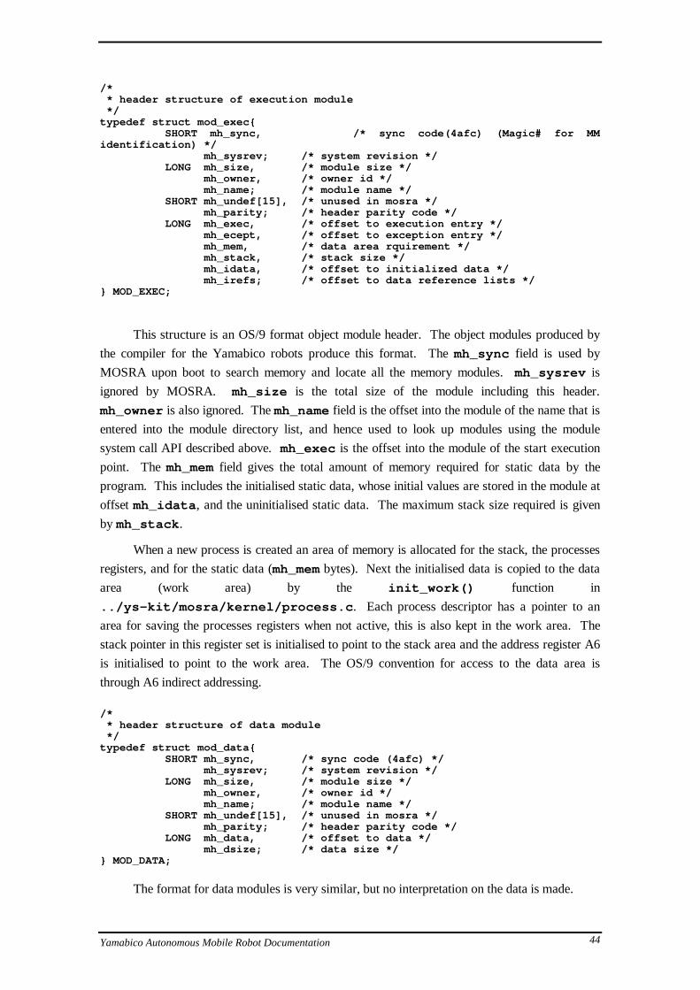
/* * header structure of execution module */typedef struct mod_exec{ SHORT mh_sync, /* sync code(4afc) (Magic# for MMidentification) */ mh_sysrev; /* system revision */ LONG mh_size, /* module size */ mh_owner, /* owner id */ mh_name; /* module name */ SHORT mh_undef[15], /* unused in mosra */ mh_parity; /* header parity code */ LONG mh_exec, /* offset to execution entry */ mh_ecept, /* offset to exception entry */ mh_mem, /* data area rquirement */ mh_stack, /* stack size */ mh_idata, /* offset to initialized data */ mh_irefs; /* offset to data reference lists */} MOD_EXEC;
This structure is an OS/9 format object module header. The object modules produced by
the compiler for the Yamabico robots produce this format. The mh_sync field is used by
MOSRA upon boot to search memory and locate all the memory modules. mh_sysrev is
ignored by MOSRA. mh_size is the total size of the module including this header.
mh_owner is also ignored. The mh_name field is the offset into the module of the name that is
entered into the module directory list, and hence used to look up modules using the module
system call API described above. mh_exec is the offset into the module of the start execution
point. The mh_mem field gives the total amount of memory required for static data by the
program. This includes the initialised static data, whose initial values are stored in the module at
offset mh_idata , and the uninitialised static data. The maximum stack size required is given
by mh_stack .
When a new process is created an area of memory is allocated for the stack, the processes
registers, and for the static data (mh_mem bytes). Next the initialised data is copied to the data
area (work area) by the init_work() function in
../ys-kit/mosra/kernel/process.c . Each process descriptor has a pointer to an
area for saving the processes registers when not active, this is also kept in the work area. The
stack pointer in this register set is initialised to point to the stack area and the address register A6
is initialised to point to the work area. The OS/9 convention for access to the data area is
through A6 indirect addressing.
/* * header structure of data module */typedef struct mod_data{ SHORT mh_sync, /* sync code (4afc) */ mh_sysrev; /* system revision */ LONG mh_size, /* module size */ mh_owner, /* owner id */ mh_name; /* module name */ SHORT mh_undef[15], /* unused in mosra */ mh_parity; /* header parity code */ LONG mh_data, /* offset to data */ mh_dsize; /* data size */} MOD_DATA;
The format for data modules is very similar, but no interpretation on the data is made.
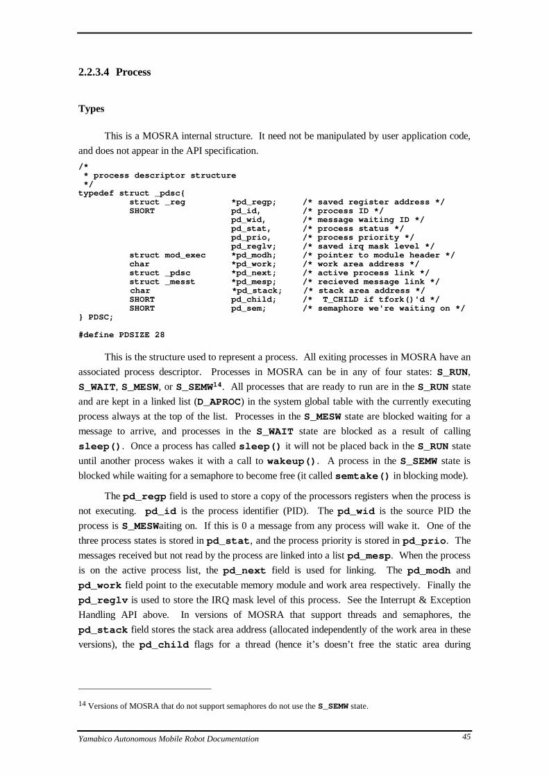
Yamabico Autonomous Mobile Robot Documentation 45
2.2.3.4 Process
Types
This is a MOSRA internal structure. It need not be manipulated by user application code,
and does not appear in the API specification.
/* * process descriptor structure */typedef struct _pdsc{ struct _reg *pd_regp; /* saved register address */ SHORT pd_id, /* process ID */ pd_wid, /* message waiting ID */ pd_stat, /* process status */ pd_prio, /* process priority */ pd_reglv; /* saved irq mask level */ struct mod_exec *pd_modh; /* pointer to module header */ char *pd_work; /* work area address */ struct _pdsc *pd_next; /* active process link */ struct _messt *pd_mesp; /* recieved message link */
char *pd_stack; /* stack area address */ SHORT pd_child; /* T_CHILD if tfork()'d */ SHORT pd_sem; /* semaphore we're waiting on */} PDSC;
#define PDSIZE 28
This is the structure used to represent a process. All exiting processes in MOSRA have an
associated process descriptor. Processes in MOSRA can be in any of four states: S_RUN,
S_WAIT, S_MESW, or S_SEMW14. All processes that are ready to run are in the S_RUN state
and are kept in a linked list (D_APROC) in the system global table with the currently executing
process always at the top of the list. Processes in the S_MESW state are blocked waiting for a
message to arrive, and processes in the S_WAIT state are blocked as a result of calling
sleep() . Once a process has called sleep() it will not be placed back in the S_RUN state
until another process wakes it with a call to wakeup() . A process in the S_SEMW state is
blocked while waiting for a semaphore to become free (it called semtake() in blocking mode).
The pd_regp field is used to store a copy of the processors registers when the process is
not executing. pd_id is the process identifier (PID). The pd_wid is the source PID the
process is S_MESWaiting on. If this is 0 a message from any process will wake it. One of the
three process states is stored in pd_stat , and the process priority is stored in pd_prio . The
messages received but not read by the process are linked into a list pd_mesp . When the process
is on the active process list, the pd_next field is used for linking. The pd_modh and
pd_work field point to the executable memory module and work area respectively. Finally the
pd_reglv is used to store the IRQ mask level of this process. See the Interrupt & Exception
Handling API above. In versions of MOSRA that support threads and semaphores, the
pd_stack field stores the stack area address (allocated independently of the work area in these
versions), the pd_child flags for a thread (hence it’s doesn’t free the static area during
14 Versions of MOSRA that do not support semaphores do not use the S_SEMW state.

Yamabico Autonomous Mobile Robot Documentation 46
death()), and the pd_sem gives the semaphore ID if the thread is blocked waiting for a
semaphore.
The source code for the MOSRA process API is located in the
../ys-kit/mosra/kernel/process.c file.
2.2.3.5 Messages
Types
/* * data structure for message */typedef struct _messt{ struct _messt *ms_next; /* pointer to the next message */ int ms_leng; /* message lengs */ SHORT ms_scid; /* message source ID */ char ms_body[2]; /* message bady */} MESST;
#define MSSIZE 12
/* * data structure for wake up message( message without message body ) */
typedef struct __messt{ struct __messt *ms_next; /* pointer to the next message */ int ms_leng; /* message lengs */ SHORT ms_scid; /* message source ID */} _MESST;
These structures are used as the header to a MOSRA type message. The data following
this header is not interpreted by MOSRA and may contain pointers, as messages are exchanged
between processes simply by pointer passing. The ms_scid is the process PID of the sender,
the ms_next field is used for linking the message into a list and the ms_leng field is the
total length of the message in bytes - header and any user data. The source code for the message
API is located in the ../ys-kit/mosra/kernel/message.c file. The
recv_mess() call will return a message from the queue pd_mesp in the callers process
descriptor, that matches the source PID (0 matches any message). If there are no matching
messages, the process is placed in the S_MESW state. The send_mess() call either places
the message on the destination processes message queue, or if the destination process was in a
S_MESW state and the message matches it’s pd_wid , then the process is placed directly in the
S_RUN state and the message pointer placed in the D0 register. This simulates a return from a
system call (since the process is in S_MESW it must have blocked on a call to recv_mess()
which never returned due to no messages being available).

Yamabico Autonomous Mobile Robot Documentation 47
2.2.3.6 Interrupts & Exceptions
Types
/* * interrupt table structure */typedef struct _irqtbl{ char *iq_poll; /* polling device address */ char iq_mask; /* mask byte */ char iq_flip; /* flip byte */ LONG (*iq_serv)(), /* interrupt service address */ iq_static; /* static storage address */ SHORT iq_prio; /* interrupt priority */ struct _irqtbl *iq_next; /* pointer for nextt irq table */} IRQTBL;
#define IQSIZE 22
/* * data structure for stacked registor at exception */typedef struct _reg{ LONG d[8], /* data register d0 to d7 */ a[7]; /* address register a0 to a6 */ SHORT sr; /* status register */ LONG pc; /* program counter */} REG;
The MOSRA interrupt mechanism is explained in the API section above. The source code
is located in the file ../ys-kit/mosra/kernel/exception.c .
2.2.3.7 System Calls & Register Usage
The mechanism for MOSRA system calls from user programs utilises the TRAP
instruction to activate a software interrupt. Specifically a TRAP #0 . Each MOSRA system call
has a system call code that is defined in the header file:
../ys-kit/mosra/defs/mosra/syscall_No.h
This call code is placed in the instruction word following the TRAP #0 instruction in the
user code. The MOSRA kernel TRAP handler then obtains the PC location of the TRAP
instruction and hence the call code from the stack. The appropriate kernel function is then
dispatched. The user program actually calls a system call stub function that performs this
process. These system call stub functions are in a user link library whose source is located in the
../ys-kit/mosra/lib/syscall directory. For example the implementation of the
mfree() stub looks as follows.

Yamabico Autonomous Mobile Robot Documentation 48
/* * mfree( adrs ) * SHORT *adrs; */
#include <mosra/syscall_No.h>
#asmmfree: trap #0 dc.w F$MFREE rts#endasm
The ../yskit/mosra/kernel/mosra68000.a file contains the _syscall
TRAP #0 handler that obtains the call code and calls the C function
syscall(fnum, arg1, arg2) in the file:
../ks-kit/mosra/kernel/exception.c
which dispatches the call. Upon return the _syscall assembly function executes the top
process on the process list - the process that was interrupted, and then does an rte instruction
(return from interrupt).
OS/9 Register Conventions
The convention for OS/9 function calling if for parameters to be placed in registers and on
the stack, and the return code is returned in register d0 . Before the call the first argument is
placed into register d0 and the second argument in register d1 . Any further arguments are
placed onto the stack in standard C convention.
The a6 register is used for the static storage address pointer15. There may be other
registers used by convention by OS/9 but no documentation was available when this was written.
15 For reasons I do not understand the value in a6 is always set to the static data address + $8000. See the
set_a6 routine in mosra68000.a and also the line p->pd_regp->a[6] = (LONG)p->pd_work +
0x8000 from pcreate() in process.c .

Yamabico Autonomous Mobile Robot Documentation 49
2.2.4 The MOSRA directory
The MOSRA directory ../ys-kit/mosra has the following structure.
|-config | |-defs----|-mosra | | |-backup |-kernel--|-objs | |-rels | | |-cstart |-lib-----|-rels | |-syscall | | |-common | |-Xterminal-|-bt-----|-get | | |-put | | |-work | | mosra-| |-lib-------|-rels | |-os9 | | | | |-backup | | | |-romance-| | |-common | |-target----| |-doc | | |-unixft-|-get | | |-put | | |-work | | | | |-common | |-unix------|-bt-----|-get | |-put | |-work |-startup

Yamabico Autonomous Mobile Robot Documentation 50
2.3 Function Modules
2.3.1 Ultrasonic sensor module
There are two implementations of the ultrasonic sensor hardware. The original Sonic
hardware and the new HiSonic hardware [Ohno95]. The interface is identical for both, however
if using the HiSonic hardware on a robot the user must define HISONIC before including the
ymbc_usr.h file.
#define HISONIC#include <ymbc_usr.h>
Both hardware versions have four US sensors, facing left, right, toward the front and
toward the back of the robot. The interface is very simple. There is a function to get the range
distance from a particular directional sensor, and a function to enable/disable some or all of the
sensors.
2.3.1.1 API
int us_dist(int dir)
Description:
This function gets the range of a detected object from the specified sensor. The
units are cm.
Parameters:
dir The direction, one of US_FRONT, US_BACK, US_LEFT or
US_RIGHT. If using the new 16 sensor ring16, you may also pass an
integer [0..15] for the sensor number to read.
Return:
The distance in cm or if no echo was detected by the sensor, the value
US_NOECHO.
16 This is the 16 sensor ring developed at Wollongong not the 12 sensor ring developed at Tsukuba.

Yamabico Autonomous Mobile Robot Documentation 51
us_mask(int mask_pattern)
Description:
The function allows the selective enabling or disabling of any of the sensors.
Parameters:
mask_pattern One of US_NOMASK, US_MASKALL or any logical AND of
US_FMASK, US_BMASK, US_LMASK, or US_RMASK to disable
selected sensors.17 Only use US_NOMASK or US_MASKALL for the
16 sensor ring.
Return:
Void.
Examples
#define HISONIC#include <ymbc_usr.h>
main(){
// Turn off all sensorsus_mask(US_MASKALL);
...
// Turn off just left and right sensorsus_mask(US_RMASK & US_LMASK);
...
// Turn on all sensors againus_mask(US_NOMASK);
}
2.3.1.2 Implementation
The implementation of the HiSonic function module software is not discussed in this
document.
17Some implementations contain a bug that causes the left and right sensors to be confused. This only affects
us_mask() . So us_mask(US_LMASK) may physically disable the right sensor, but the software will still
return US_NOECHO for the distance on the left sensor - hence both left and right will be unusable.

Yamabico Autonomous Mobile Robot Documentation 52
2.3.1.3 Directory
|-defs |-hard |-lib | HiSonic-|-master-|-rels |-mmacro | |-module-|-rels |-rom
|-SON----|-rels |-defs |-lib | SONic---|-master-|-rels |-mmacro | |-module-|-rels |-rom

Yamabico Autonomous Mobile Robot Documentation 53
2.3.2 ISeye Software United Environment (ISSUE)
The ISSUE module includes the Adjustment and Interactive Drawing Tool (AID), Path
Search Sensor (PaSS) and IASensor yoked (AIS) systems in an integrated environment. The
ISSUE API is currently undocumented18.
2.3.2.1 Directory
|-defs | |-lib----|-rels | |-master-|-rels | | |-AID------|-rels | | | | |-objs | |-IAS------|-params ISSUE-|-module-| |-rels | | | |-IScommon-|-rels | | | |-PaSS-----|-objs | | |-rels | | | |-eye_bank-|-rels |-rom |-sample
18ISSUE is not used in the Wollongong laboratory.

Yamabico Autonomous Mobile Robot Documentation 54
2.3.3 Spur (Locomotion module)
The vehicle command subsystem, or locomotion module is responsible for accepting hight
level motion commands from the master module and controlling the wheel motors appropriately.
It also uses the wheel shaft encoders to count wheel rotations and maintain odometry information.
The software is named Spur. For a detailed description of Spur see “Vehicle Command System
and Trajectory Control for Autonomous Mobile Robots” [Iida91]19.
Spur maintains three independent coordinate systems in (x,y,q). Global coordinates (GL)
which are initially (0,0,0) when the robot is powered-on. These coordinates are typically used for
mapping. The Local coordinates (LC) are an independent coordinate set that can be set relative
to the GL coordinates, for example for negotiating an obstacle before returning to the previous
tracked path. Lastly, the Front Side (FS) coordinate system is always relative to the robot. The
(0,0,0) position is at the centre of the robot looking forward. See the diagram below.
θLC
θGL
OGL
YGL
XGL
OLC
YLC
XLCOFS
YFS
XFS
The relationship between Spur coordinate systems.
The Spur commands can be divided into the following categories:
• Line and Arc Tracking
• Coordinate system setting
• Locomotion error adjustment
• Velocity and Acceleration control
• Other - Stopping, Spinning, Retrieving coordinates
Unless otherwise indicated all distance units are in millimetres (mm), and angles are
measured in degrees. Note that many Spur commands have an alternate version suffixed with
_cm. These use distance units of centimetres (cm) instead of millimetres. Velocity is always
measured in cm.s-1.
19This paper can be located in the English version of the Yamabico Hardware documentation folder [Yam95].

Yamabico Autonomous Mobile Robot Documentation 55
2.3.3.1 API
Spur_line_GL(int x,int y,int th)
Spur_line_LC(int x,int y,int th)
Spur_line_FS(int x,int y,int th)
Spur_line_GL_cm(int x,int y,int th)
Spur_line_LC_cm(int x,int y,int th)
Spur_line_FS_cm(int x,int y,int th)
Description:
These commands instruct Spur to track along the line passing through the point
(x,y) in the direction th in the designated coordinate system until further notice. See
[Iida91] for a diagram.
Parameters:
x,y Cartesian Coordinate position that tracking line passes through.
th Angle tracking lines makes with the coordinate system 0o line.
Return:
Void.
Example
In this example the robot will track along a line at 45o to the Global X coordinate axis. If
it is at it’s starting location it will track along a line 45o to the right of the robot looking forward.
Note that the robot will not rotate to 45o then track forward, but rather will start moving forward
immediately at 0o, then veer right until it reaches the specified line.
#include <ymbc_usr.h>
main(){
Spur_line_GL(0,0,45);}

Yamabico Autonomous Mobile Robot Documentation 56
Spur_arc_c_GL(int x,int y,int r)
Spur_arc_c_LC(int x,int y,int r)
Spur_arc_c_FS(int x,int y,int r)
Spur_arc_c_GL_cm(int x,int y,int r)
Spur_arc_c_LC_cm(int x,int y,int r)
Spur_arc_c_FS_cm(int x,int y,int r)
Description:
These commands instruct Spur to track along an arc with centre (x,y) and radius |r|.
The rotational direction is counter-clockwise for positive r and clockwise for negative r.
See [Iida91] for a diagram.
Parameters:
x,y Cartesian Coordinate position that tracking arc is centred on.
r Radius of tracking arc. Sign determines direction of rotation.
Return:
Void.
Spur_arc_t_GL(int x,int y,int th, int r)
Spur_arc_t_LC(int x,int y,int th, int r)
Spur_arc_t_FS(int x,int y,int th, int r)
Spur_arc_t_GL_cm(int x,int y,int th, int r)
Spur_arc_t_LC_cm(int x,int y,int th, int r)
Spur_arc_t_FS_cm(int x,int y,int th, int r)
Description:
These commands instruct Spur to track along an arc which touches the tangent
through the point (x,y) with direction th and arc radius r. The rotational direction is
counter-clockwise for positive r and clockwise for negative r. See [Iida91] for a diagram.
Parameters:
x,y Cartesian Coordinate position that tracking arc tangent is centred on.
th Angle of tangent line.
r Radius of tracking arc. Sign determines direction of rotation.

Yamabico Autonomous Mobile Robot Documentation 57
Return:
Void.
Spur_stop_GL(int x,int y,int th)
Spur_stop_LC(int x,int y,int th)
Spur_stop_FS(int x,int y,int th)
Spur_stop_GL_cm(int x,int y,int th)
Spur_stop_LC_cm(int x,int y,int th)
Spur_stop_FS_cm(int x,int y,int th)
Description:
These commands instruct Spur to stop the robot when it gets close to the position
(x,y) and angle th. Because of non-holonomic constraints the actual stoping position may
no be exactly (x,y,th).
Parameters:
x,y,th Stopping position and angle.
Return:
Void.
Spur_stop_q()
Spur_stop_Q()
Description:
These two identical commands stop the robot with maximum acceleration. The
preferred command to use is Spur_stop_q() .
Parameters:
None.
Return:
Void.

Yamabico Autonomous Mobile Robot Documentation 58
Spur_spin_GL(int th)
Spur_spin_LC(int th)
Spur_spin_FS(int th)
Description:
These commands instruct Spur to spin the robot on the spot to the angle th. This
command will cause the robot to stop after the turn is completed.
Parameters:
th Angle to turn to.
Return:
Void.
Spur_adjust_pos_GL(int x,int y,int th)
Spur_adjust_pos_LC(int x,int y,int th)
Spur_adjust_pos_FS(int x,int y,int th)
Spur_adjust_pos_GL_cm(int x,int y,int th)
Spur_adjust_pos_LC_cm(int x,int y,int th)
Spur_adjust_pos_FS_cm(int x,int y,int th)
Description:
These commands adjust the current coordinates of the robot in the specified
coordinate system to the values supplied. This does not change the absolute values of
coordinates used in the current tracking command being executed. Hence the effect is to
modify the robot’s notion of where it is in the coordinate space. This is typically used to
correct accumulated odometry errors when other sources of position information are
available, for example sensed landmarks.
Parameters:
x,y,th The new values of the coordinates in the specified coordinate system.
Return:
Void.
Yamabico Autonomous Mobile Robot Documentation 59
Example
In this example the robot is tracking along a straight line directly forward. Then the
coordinate system is adjusted so as to translate it to the robot’s left. The effect of this will be that
the robot veers right to track back onto the specified line through (0,0) at 0o which is now to it’s
right in the coordinate space.
#include <ymbc_usr.h>
main(){
Spur_line_LC(0,0,0); // Track straight forward
set_timer(5*SEC); // let the robot go forward for 5 secondstimer_wait();
Spur_adjust_pos_LC(0, 300, 0); // This actually translates thecoordinate
// system left 30cm and back by the// amount the robot has already
traveled// in the X direction, but as the
line// command specifies an infinite
line, it// makes no difference to x.
}
Spur_set_LC_on_GL(int x,int y,int th)
Spur_set_LC_on_LC(int x,int y,int th)
Spur_set_GL_on_GL(int x,int y,int th)
Spur_set_LC_on_GL_cm(int x,int y,int th)
Spur_set_LC_on_LC_cm(int x,int y,int th)
Description:
These commands change the current coordinates of the first specified coordinate
system to the values supplied relative to the second specified coordinate system. This is
not a motion command but just changes Spur's coordinate values. It also changes the
absolute coordinate values used in the current tracking state. Hence the motion of the
robot will not be effected.
Parameters:
x,y,th Values of the new coordinates relative to the second specified
coordinate system.
Return:
Void.

Yamabico Autonomous Mobile Robot Documentation 60
Spur_set_pos_GL(int x,int y,int th)
Spur_set_pos_LC(int x,int y,int th)
Spur_set_pos_GL_cm(int x,int y,int th)
Spur_set_pos_LC_cm(int x,int y,int th)
Description:
These commands change the coordinates of the specified coordinate system to the
values supplied. This is not a motion command but just changes Spur's coordinate values.
It also changes the absolute coordinate values used in the current tracking state. Hence the
motion of the robot will not be effected.
Parameters:
x,y,th Values of the specified coordinate system relative to it's current values.
Return:
Void.
Spur_set_vel(int vel)
Spur_set_vel_cm(int vel)
Description:
This command instructs Spur to change the current maximum velocity (reference
velocity) of the robot. If tracking the robot will accelerate until the desired velocity is
reached.
Parameters:
vel The new reference velocity.
Return:
Void.

Yamabico Autonomous Mobile Robot Documentation 61
Spur_set_ang_vel(int angv)
Description:
This command instructs Spur to change the current maximum angular velocity of
the robot.
Parameters:
angv The new reference angular velocity.
Return:
Void.
Spur_set_accel(int acc)
Spur_set_accel_cm(int acc)
Description:
This command instructs Spur to change the current maximum acceleration of the
robot.
Parameters:
acc The new maximum acceleration.
Return:
Void.
Spur_set_ang_accel(int alpha)
Description:
This command instructs Spur to change the current maximum angular acceleration
of the robot.
Parameters:
alpha The new maximum angular acceleration.
Return:
Void.

Yamabico Autonomous Mobile Robot Documentation 62
Spur_servo()
Description:
This command instructs Spur to engage the motor servoing if it is not already
engaged. The robot will not be free-wheeling once it has been engaged. Any attempt to
move the robot manually will cause the robot to attempt to accelerate and move back to it's
current global coordinates.
Parameters:
None.
Return:
Void.
Spur_servo_free()
Description:
This command instructs Spur to free the motor servoing. The robot will then be
free-wheeling and may be manually pushed. Note that Spur still keeps odometry
information up-to-date. Hence the robot will still know it's current global position after
being manually pushed.
Parameters:
None.
Return:
Void.
Spur_get_pos_GL(int *x0,int *y0,int *th0)
Spur_get_pos_LC(int *x0,int *y0,int *th0)
Spur_get_pos_GL_cm(int *x0,int *y0,int *th0)
Spur_get_pos_LC_cm(int *x0,int *y0,int *th0)
Description:
These commands obtain the current coordinate values in the specified coordinate
system.

Yamabico Autonomous Mobile Robot Documentation 63
Parameters:
x0,y0,th0 The current coordinates in the specified coordinate system. Note that
the address of variables of int type must be supplied to receive the
values.
Return:
Void.
Spur_get_vel(int *vel,int *angv)
Spur_get_vel_cm(int *vel,int *angv)
Description:
These commands obtain the current linear and angular velocities. Note that the
address of variables of int type must be supplied to receive the values. These are the
reference maximum velocities not the actual current velocity of the robot. Use
Spur_near_vel() or Spur_near_ang_vel() to test the current robot velocities.
Parameters:
vel The current linear velocity.
angv The current angular velocity.
Return:
Void.
int Spur_near_pos_GL(int xx, int yy, int r)
int Spur_near_pos_LC(int xx, int yy, int r)
int Spur_near_pos_GL_cm(int xx, int yy, int r)
int Spur_near_pos_LC_cm(int xx, int yy, int r)
Description:
This call determines if the robot is near the specified position (x,y) within a
tolerance radius r.
Parameters:
xx,yy Cartesian coordinate position the robot may be near.
r The tolerance radius.
Return:
TRUE if near the specified coordinates within the tolerance, FALSE if not.

Yamabico Autonomous Mobile Robot Documentation 64
int Spur_near_ang_GL(int ang,int error)
int Spur_near_ang_LC(int ang,int error)
Description:
This call determines if the robot's angle is near the specified angle ang within an
error angle error .
Parameters:
ang Angle the robot may be near.
error The error tolerance angle.
Return:
TRUE if near the specified angle within the tolerance, FALSE if not.
int Spur_near_vel(int vel,int error)
int Spur_near_vel_cm(int vel,int error)
Description:
This call determines if the robot's current velocity is near the specified velocity vel
within an error tolerance error .
Parameters:
vel The velocity the robot may be near.
error The error tolerance velocity.
Return:
TRUE if near the specified velocity within the tolerance, FALSE if not.

Yamabico Autonomous Mobile Robot Documentation 65
int Spur_near_ang_vel(int angv,int error)
Description:
This call determines if the robot's current angular velocity is near the specified
angular velocity angv within an error tolerance error .
Parameters:
angv The angular velocity the robot may be near.
error The error tolerance angular velocity.
Return:
TRUE if near the specified angular velocity within the tolerance, FALSE if not.
Spur_over_line_GL(int xx,int yy,int th)
Spur_over_line_LC(int xx,int yy,int th)
Spur_over_line_GL_cm(int xx,int yy,int th)
Spur_over_line_LC_cm(int xx,int yy,int th)
Description:
This call determines if the robot is over the line through (xx,yy) at angle th.
Parameters:
xx,yy Point which line passes through.
th Angle of the line.
Return:
TRUE if the current position is over the specified line20, FALSE otherwise.
2.3.3.2 Implementation
The Spur locomotion system is currently implemented as an independent function module
on a Yamabico CPU bus card. The source for this implementation can be located in the directory
../ys-kit/module/Spur-16/module . The implementation at the algorithmic level is
not discussed in this document, but is discussed in [Iida91A, Iida91]. What follows is a brief
overview of the function of the source code. A description of the locomotion software in the
20Need to clarify exactly what 'over the line' means.

Yamabico Autonomous Mobile Robot Documentation 66
context of communication with the master module is also given in the case study of Section 2.4
Inter-module Communication and the Yamabico Bus.
The Spur software is interrupt driven. The startup module
(../module/startup.c ) that is loaded onto the locomotion board starts romance as usual,
then mfork() ’s the spur module. The Spur main function from spur.c , calls
_spur_init() then busy-wait’s in an infinite loop. The _spur_init() function carries
out the following steps in sequence .
Initialises the hardware pointers - _hwinit()
The Spur software access three types of Yamabico hardware. The communication of
locomotion commands from the master module and state information to the master module is
via Dual Port Memory (DPM). A description of this mechanism and the DPM is in section
2.4. The Programmable Timer Module (PTM) is used to deliver periodic interrupts to the
CPU and activate the interrupt routine which ultimately does the work of the locomotion
software. The 4 Channel Pulse Width Modulator Signal Generator (PWM) is used to control
the motor currents independently.
This function initialises the pointer variables ptm , dpm, pwm, mode, and cnt to point
to the respective hardware addresses. The cnt and mode variables are for wheel shaft
encoder feedback.
Initialises the software state variables - _swinit()
This function initialises the variables that represent the dynamic state of Spur. This
includes resetting the coordinate system, setting the initial acceleration and velocity to 0,
calculating initial gains for the motors from the velocity and setting the current mode to stop.
The current mode of Spur is represented by the cmode variable. This is a C
structure/union with substructures that look as follows (from ../Spur-
16/defs/mode_ctl.h )
/* for mode control structure */struct mode_ctl_str { char mode; /* Control mode */ union mode_para para;};
union mode_para { struct line_para_str line_para; struct accel_para_str accel_para; struct stop_para_str stop_para; struct circle_para_str circle_para;};
/* for line trace mode parameters */struct line_para_str { int x_org; int y_org; int th_org;};
/* for acceleration mode */struct accel_para_str { int vel;};

Yamabico Autonomous Mobile Robot Documentation 67
/* for stop mode parameters */struct stop_para_str { int x_stop; int y_stop; int th_stop; int sumx; int sumth;};
struct circle_para_str { int x_cent; int y_cent; int radi;};
The major modes are STOP, LINE , CIRCLE, FREE, and ACCEL. The modes and
their associated parameters are self explanatory.
Sets up the table data - _tblinit()
This function initialises a table tbl[] for 2D current control. The data for the table is
different for each robot body and is included from a file in the ../table/tdata directory.
Registers an interrupt routine for the PTM - _reg_ptm()
This function registers an interrupt routine for the PTM. The routine is timirq()
from ../module/timirq.c . This will be called every 5ms.
Registers an interrupt routine for the DPM - _reg_pdm()
This function registers an interrupt routine for the DPM. The routine is dpmirq()
from ../module/dpmirq() . This will be called when the master module writes a Spur
command into the SIMP. See section 2.4 for details.
Initialises the PWM hardware - _initpwm()
This function simply initialises the PWM hardware.
Initialises the DPM hardware - _initpdm()
This function clears the DPM SIMP and command areas.
Initialises the PTM hardware - _initptm()
This function initialises the PTM to interrupt the CPU at 5 millisecond (ms) intervals.
Once initialisation is complete the main program busy waits in an infinite loop. The work
is then carried out by the timirq() and dpmirq() routines. The dpmirq() routine is
activated when the master module writes a new command into the DPM. This invokes the
appropriate command function which just modifies the current state of Spur (cmode) to reflect
the requested command action. This is explained in section 2.4.
The timirq() function calls read_cnt() to read the current wheel encoder counter
values, then calls the feedback control routine fb_ctl() (timirq.c ). The fb_ctl()

Yamabico Autonomous Mobile Robot Documentation 68
function calls on other functions to calculate various values, such as the robot velocity
(cal_r_vel() ), depending on the current mode. It implements the feedback control as
described in the paper [Iida91A]. The cal_r_vel() function also updates the DPM SIMP
information making it available to the master module. Hence the SIMP is updated every 5ms.
To summarise, the architecture looks as follows.
Interrupt
Yamabico Bus II
Master Module
Locomotion Module
User program linked with lib_source...Spur_line_GL(0,0,0)
send_com16()
dpm = command & srgs...
Spur_get_pos_GL(&x,&y,&th)
rd_SIP()
x = dpm...
dpm_irq()
D P M
com_ana()
cmode = dpm
Timer chip Motor hardware
Every 5msInterrupts
tim_irq()
fb_ctl()
cal_r_vel()
wt_SIP()
dpm = Spur state
mode_ctl()
switch (cmode.mode)
do_ line_track ()
pwm-> ... = ...count = cnt[M_ xx ]
Control Motors
Encoder counters
Spur locomotion software and Master module architecture

Yamabico Autonomous Mobile Robot Documentation 69
2.3.3.3 Directory
|-DPM |-defs |-doc |-exp |-lib | |-lib_source--|-rels | |-line_tr_sim-|-data | |-setup | |-master------|-obj | |-rels | |-module------|-obj | |-rels Spur-|-obavo |-rom |-rr1 |-rr2 |-rr_avo |-sample |-simlib |-simulator | | |-mktable |-table-------|-setup | |-tdata | |-tempdir |-tosim

Yamabico Autonomous Mobile Robot Documentation 70
2.3.4 Voice generator module
The voice generation function module has the ability to say numbers in decimal and
hexadecimal21, string of romanji characters, and pre-recorded sample modules. All requests for
speech are queued and the function returns to the caller immediately. See the document ys-
kit/module/Voice/doc/library_func.txt for Japanese documentation.
A description of the available functions is given below22.
2.3.4.1 API
voice_init()
Description:
This function initialises the voice function module and must be called prior to usage
of any other voice module functions.
Parameters:
None.
Return:
Void.
voice_set(int amp, int rate)
Description:
Set the amplitude and rate of spoken voice.
Parameters:
amp Amplitude.
rate Rate.
Return:
Void.
21Only in Japanese
22The Voice module is not used at the Wollongong laboratory, hence the documentation is incomplete.

Yamabico Autonomous Mobile Robot Documentation 71
v_boadCHK(int boad)
Description:
Check the existence of the specified Board and if detected plays a recorded message
indicating the board is OK. The check is done by checking the accessibility of the board’s
DPM. The recorded message data is read from a data memory module of sampled data
with pre-defined names for each board. The pre-defined sample module names are:
sonic_ok , eye_ok , spur_ok and voice_ok .
Parameters:
boad The board to check23. This is actually the address of the board’s
DPM. These are defined in vusr.h .
Return:
Void.
Example
#include <ymbc_usr.h>#include <vusr.h>
main(){
/* Check sonic, ISeye, and Spur boards. Voice will announce OK messageif the board is OK */
v_boadCHK(SON);v_boadCHK(ISe);v_boadCHK(SPR);
}
sayd(int num)
Description:
Say the specified decimal.
Parameters:
num Number to say.
Return:
Void.
23Note boad is just a Japanese misspelling of Board.
Yamabico Autonomous Mobile Robot Documentation 72
sayx(int num)
Description:
Say the specified hexadecimal number.
Parameters:
num The number to say.
Return:
Void.
says(int num)
Description:
Say the pre-defined sentence stored on the voice module with index number num.
All the pre-defined sentences are currently in Japanese.
Parameters:
num Index of pre-defined sentence to say.
Return:
Void.
sayw(char *str)
Description:
Say the romanji string specified24.
Parameters:
str The romanji string to say.
Return:
Void.
24Note that the current implementation is intended to speak Japanese, hence some characters are converted.
Specifically ‘l’ -> ‘r’, ‘v’ -> ‘b’, ‘j’ -> ‘z’ and ‘c’ -> ‘s’.

Yamabico Autonomous Mobile Robot Documentation 73
speakf(char *fmt, int ag1, int ag2,...,int ag9)
Description:
Say a C printf style formatted string.
Parameters:
fmt The format string. This parameter is similar to, but more restricted
than, C’s printf() format function. The allowable format specifiers are:
• %c character
• %d integer (decimal)
• %x integer (hexadecimal)
• %a set amplitude to arg and rate to default
• %r set rate to arg and amplitude to default
agN N = [1..9], the arguments
Return:
Void.
sayp(char *str)
Description:
Play the pre-recorded sounds memory module with the specified name.
Parameters:
str The name of an existing MOSRA memory module containing the
sample data.
Return:
Void.

Yamabico Autonomous Mobile Robot Documentation 74
say_flush(int thre)
Description:
This function is for flushing the queued say requests. If the number of queued
requests is greater than thre then the oldest requests are aborted/dequeued leaving only the
newest thre requests.
Parameters:
thre The thresh-hold number of requests to leave queued.
Return:
Void.
int say_ended(int rest)
Description:
This function returns TRUE if the number of queued voice requests on the voice
module is equal to rest , FALSE otherwise.
Parameters:
rest Test number of remaining requests.
Return:
TRUE if remaining requests queued is rest , FALSE otherwise.
2.3.4.2 Implementation
The implementation of the voice module is not discussed in the document.

Yamabico Autonomous Mobile Robot Documentation 75
2.3.4.3 Directory
|-defs |-doc |-hard |-lib |-lib_source |-master | | |-etc | | | |-j50--|-j50 | |-datae7--|-num | | |-sent | | |-wd | | | | |-etc | | |-j50 Voice-|-mkv--------|-datae9--|-num | | |-sent | | |-wd | | | | |-etc | | | | | |-j50--|-j50 | |-dataea--|-num | |-sent | |-wd | |-module-----|-objs | |-rels |-pcmdata1 |-pcmdata2 | |-rom--------|-startup |-test

Yamabico Autonomous Mobile Robot Documentation 76
2.3.5 Timer functions
The timer functions are not implemented in a separate function module, but as an
independent process that executes on the master module. The set_timer() and
timer_wait() function interact with the TIMER process, hence blocking the process that
calls timer_wait() until the time expires. The read_SRTKEI() and compSRTKEI()
function simply read the global system timer.
2.3.5.1 API
set_timer(int count)
Description:
This function is used in conjunction with the timer_wait() function to delay
execution for a specific amount of time. Other program code may execute between the
set_timer() ...timer_wait() pair provided it does not take longer than count
1/100Th
of a second to execute. Note that the definition SEC==100 is available.
Parameters:
count Number of 1/100Th
of a second to delay.
Return:
Void.
timer_wait()
Description:
This function is used in conjunction with the set_timer() function to delay
execution for a specific amount of time. Once called the execution is delayed until the
count time has expired from when set_timer() was called.
Parameters:
None.
Return:
Void.

Yamabico Autonomous Mobile Robot Documentation 77
int readSRTKEI()
Description:
This function returns the current value of the quasi-real time clock. The units are
10 msec.
Parameters:
None.
Return:
Current time in units 10 msec.
int compSRTKEI(int t0,int time)
Description:
This function compares the value of the specified times. If time represents a time
greater that of equal to t0 TRUE is returned.
Parameters:
t0 Initial time to compare. Units are 10 msec.
time time to compare with t0 .
Return:
TRUE if time > t0 , FALSE otherwise.
2.3.5.2 Implementation
The set_timer() and timer_wait() functions can be found in the file
../ys-kit/module/mmKEI/lib/timer6340.c 25. The set_timer() function
allocates and sends a struct timess message to the TIMER process (PID TIMEMON). The
TIMER process is implemented in ../ys-kit/module/mmKEI/iomon/timer.c . The
main loop wait for incoming messages, and retains a list of timer requests. As each timer request
expires a message is sent back to the sending process. The TIMER process uses interrupts from
the timer device to efficiently wait for times to expire without busy waiting. When a process
makes a call to wait_timer() , wait_timer() just blocks waiting for a message from the
TIMER process.
25 For other Master Module versions the directory will be other than mmKEI. For example the Wollongong version
of the master module source is in the mmW directory.

Yamabico Autonomous Mobile Robot Documentation 78
The readSRTKEI() and compSRTKEI() functions are implemented in the file
../ys-kit/module/mmKEI/lib/srt_KEI.c . They simply read and compare against
the free running system timer.
2.3.6 Whisker functions
Some Yamabico robots have a number proportional passive whisker sensors26. These are
accessed by the whisker library API. This whiskers are accessed by an integer index [0..7] or by
the PCB socket numbers WJ_3 … WJ_10. Some synonyms also exist (WLeftFront ,
WLeftBack , WFrontRight and WFrontLeft ).
2.3.6.1 API
ReInitWhiskers()
Description:
This function initialises or re-initialises the whisker software. It must be called prior
to calling any other whisker functions. The whisker module will not access the whisker
hardware or execute until this function is called. Hence it is acceptable to have the whisker
module in ROM and running on a robot that has no whiskers connected, as it will do
nothing until this function is called.
Parameters: None.
Return: None.
26 Currently only Flo at the Wollongong laboratory. The implementation currently connects the hardware to the
master module, and hence the whisker module is an executable module on the master module ROM.

Yamabico Autonomous Mobile Robot Documentation 79
CalibrateWhisker(int whisker)
Description:
This function calibrates the centre position of the specified whisker to it’s current
physical position. This is called to set the current physical position (usually the rest
position) to the 0 point. The readings will then be positive or negative depending on the
direction of deflection.
Parameters:
whisker The whisker number to calibrate.
Return: None.
int ReadWhisker(int whisker)
Description:
This is the main function used to read whisker values. The values returned have
been adjusted to the calibrated centre (and hence are signed values), possibly reversed in
sense and are averaged over a number of samples (set using SetNoSampAverage() ).
Parameters:
whisker The whisker number to read the current averaged value of.
Return:
The whisker sensor value.
int ReadRawWhisker(int whisker)
Description:
This function returns the raw value of a whisker sensor reading as obtained from the
hardware A/D converter. It is not averaged or centre calibrated.
Parameters:
whisker The whisker number to read the current raw value of.
Return:
The whisker sensor value.

Yamabico Autonomous Mobile Robot Documentation 80
int SetSampleFreq(int FreqHz)
Description:
The whisker module samples each whisker at a fixed sampling rate (all whiskers at
the same rate). This call is used to change the default rate or to disable sampling. The
default is 20Hz and the valid range is 1Hz…60Hz. A value of 0 will turn off sampling
and the whisker module will no longer use the CPU until the frequency is reset (or
ReInitWhiskers() is called).
Parameters:
FreqHz The whisker sampling frequency in Hz or 0.
Return:
The old sampling frequency (current previous to the call).
int SetNoSampAverage(int NoSamples)
Description:
This function is sets the number of sample over which the read whisker values are
averaged. The default is 5 and the valid range is [1..50]. If the value 0 is passed the
whisker module will not do averaging at all. In this case the result of calling
ReadWhisker() will be meaningless, but the raw un-averaged values may be read
using ReadRawWhisker() .
Parameters:
NoSamples The number of samples to average over, or 0 to disable calculation of
average values.
Return: Undefined.
Yamabico Autonomous Mobile Robot Documentation 81
SetDebug(int Channel)
Description:
The whisker module can send debugging output to either the ROMANCE or
RADNET consoles. This is useful to display a continuous readings of whisker values
when calibrating hardware etc. If averaging has been disabled, only raw values will be
displayed.
Parameters:
Channel One of CON, NET or -1. To disable debugging pass -1 (the default),
to enable display of whiskers every one second specify which console.
Return: None.
SetSense(int whisker, int Sense)
Description:
It is sometimes desirable to reverse the numeric range of the sensor readings, for
example if the whisker connector was wired backwards.
Parameters:
whisker The whisker number to set the sense of.
Sense Either 1 or -1. If 1 the sense is as read from the hardware, if -1 the
sense is reversed
Return: None.
QuitWhiskers()
Description:
Calling this function causes the whisker module to exit. (Calls death() , and
hence can be unlinked or restarted with execute). Issuing whisker calls after this will cause
the caller to block forever. Even if the whisker module is restarted, client programs must
call ReInitWhiskers() again.
Parameters: None.
Return: None.

Yamabico Autonomous Mobile Robot Documentation 82
2.3.6.2 Implementation
The current implementation is just an executable module that runs on the master module.
The library calls communicate with it via message passing, with the exception of
ReadWhisker() and ReadRawWhisker() , which just read from an array of values shared
between the whisker module and the clients. The address of this array is passed from the whisker
module to a client when ReInitWhiskers() is called. The whisker module accesses a
multiplexed Analogue to Digital (A/D) converter via the master module parallel port. The
whiskers themselves are currently just variable rotary potentiometers. The sampling rate is
achieved just by using the timer module functions, and hence two messages are exchanged every
sampling period. For this reason the sampling period should not be set too high or the CPU will
be loaded with message passing between the whisker module and the timer module27. This timing
method may change in the future.
27 There seems to be a bug in the timer module software where by occasionally it doesn’t reply to a timer request
(wait_timer() never returns). This seems only to show up when messages are sent at a high rate as with the
whisker module.

Yamabico Autonomous Mobile Robot Documentation 83
2.3.7 ROMANCE & RADNET console functions
The ROMANCE and RADNET console functions are used to do Input/Output through
one of the serial ports on each CPU board. The ROMANCE functions are used for the first port
(which is usually connected using a cable to a UNIX host executing the romanceu program).
The RADNET network functions use the second port and communicate with a UNIX host
running the RADNET software. Ultimately the output goes to the radcon console utility. The
RADNET Host software is documented in a later section.
2.3.7.1 ROMANCE API
write_cons(char *form_str)
write_cons(char *form_str, int data)
write_cons(char *form_str, char *data)
Description:
This function is for output to the romance console. The function is similar to, but
more restricted than, C’s printf() function. The allowable format specifiers are:
• %c character
• %s C string
• %d integer (decimal)
• %x integer (hexadecimal)
• %b integer (binary)
Parameters:
form_str A format string in the printf() style, but write_cons() only
allows 0 or 1 format specifiers in the string.
Return:
Void.
char *read_cons(char *form_str, char *data, int *count)
Description:
This function is for input from the romance console. The function is similar to,
but more restricted than, C’s scanf() function. The allowable format specifiers are:
• %c character
• %s C string
• %d integer (decimal)

Yamabico Autonomous Mobile Robot Documentation 84
• %x integer (hexadecimal)
• %b integer (binary)
Parameters:
form_str A format string in the scanf() style. The format specifiers are
limited to those listed above.
data The address of an appropriate type of variable at which the input will
be stored.
count The address of an integer into which the number of bytes read from the
console will be stored.
Return:
Unknown.
2.3.7.2 RADNET Console API
RADNET provides two functions that closely mimic the behaviour of the ROMANCE
functions above. These functions, however, interact with the user via the radcon console utility
which may run on any UNIX machine. The radcon utility connects to the RADNET link
server, and hence the robot, via the Internet. For more details see the RADNET documentation
later in this document.
write_port(int Channel, char *form_str)
write_port(int Channel, char *form_str, int data)
Description:
This function is for output to the romance or RADNET console. The parameters
are similar to write_cons() .
Parameters:
Channel One of CON or NET. If CON the output will go to the romance console,
if NET the output will go to the RADNET console.
form_str As for write_cons() .
Return:
Void.
Yamabico Autonomous Mobile Robot Documentation 85
read_port(int Channel, char *form_str, char *data, int *count)
Description:
This function is for input from the romance or RADNET console. The
parameters are similar to read_cons() .
Parameters:
Channel One of CON or NET. If CON the input will come from the romance
console, if NET the input will come from the RADNET console.
form_str, data, count As for read_cons() .
Return:
Void.
2.3.7.3 ROMANCE Implementation
The console functions use ROMANCE to do I/O through the serial port (using the ACIA
device). ROMANCE is implemented as an independent MOSRA process. One function of
ROMANCE is to provide a menu interface via the serial port to the host computer to allow
program upload/download, memory module manipulation and other services. The other function
is to provide the console I/O described here.
The ROMANCE source code is located in the ../ys-kit/mosra/romance
directory. Communication with the user program process is via the MOSRA message passing
facility (see MOSRA API section). The console functions described above just send a MOSRA
message to the ROMANCE process, which has a pre-defined process ID. The receipt of a
message wakes the main loop in the ROMANCE process and it carries out the I/O via the serial
port. The actual serial I/O is interrupt driven. The ROMANCE process installs an interrupt
handler for the serial port when first started by the startup module.
The write_cons() and read_cons() function are available to user programs by
linking with the romancelib.l library, hence are implemented in the ../romance/lib
directory (write_cons.c and read_cons.c ). These functions simply call the read/write
routines provided in the writefunc.c and readfunc.c source files. For example,
_cwritech() creates a message of type MESST (standard MOSRA message header type) and
sends it to ROMANCE.

Yamabico Autonomous Mobile Robot Documentation 86
_cwritech(dir,str,count)char dir;char *str;int count;{ MESST *m; int i,l,head;
... m=(MESST *)malloc(10+l); m->ms_scid=getpid(); m->ms_leng=l; m->ms_body[0]=STX; m->ms_body[1]='W'; for (i=0;i<count;i++) m->ms_body[head+i]=str[i]; m->ms_body[l-1]=NULL; /* STX W < data > NULL */ if (dir==STDOUT){ m->ms_body[2]=SI; /* STX W SI <data> SO NULL */ m->ms_body[l-2]=SO; } if (send_mess(ROMANCE,m)) return(1); /* send to ROMANCE */ else return(0);}
The ROMANCE process source is located in the directory ../romance/target .
When ROMANCE receives this message in it’s main loop in the wait() function (main.c ),
it calls the message() function to process the message. If, for example, the message indicated
a write (body[1] == ‘W’ ), then message() calls writestr() which actually outputs
the string to the ACIA’s serial port (using writech() ).
2.3.7.4 Directory
|-lib------------|-rels |-os9 | | |-backup | |romance----| | |-doc |-target---------| |-common | |-unixft---|-get | |-put | |-work | | |-common |-unix-----------|-get |-put |-work

Yamabico Autonomous Mobile Robot Documentation 87
2.4 Networking
The Yamabico Radio Network RADNET28 is a software system that enables two-way
communication between any number of Yamabico's and host computers. It consists of software
components for both the Robot and host machines on a network. The current implementation
executes the robot software on the master module and communicates over point-to-point radio
modem links connected via the master module serial port. The host side of the link is a UNIX
workstation with the radio modem also connected via a serial port.
The Network API on the robot side provides user programs, currently under MOSRA,
with services for sending and receiving unreliable datagrams. Datagrams are addressed using IP
numbers, where the robots have special numbers starting at zero, and a port number. Using ports
it is possible to have a large number of independent channels of communication with another
robot or host machine. The API on the host machine is provided by a client link library. This
provides a similar datagram API as available on the robot in addition to functions for directly
accessing Spur locomotion functions remotely and up/downloading OS/9 modules over the link.
User utility programs are provided for convenient interaction and control of the robots
(downloading programs and executing them, etc.). These programs rely on the client library for
communication with the robots.
The following sections document the general RADNET architecture, the user programs,
and the robot and host side client API’s.
2.4.1 Architecture
The RADNET software supports multiple robots each with a point-to-point link between
the robot and a UNIX host. The host need not be the same machine for each robot, although if
the host supports multiple serial ports it is possible to connect multiple radio modems. The host
end of each robot link runs a copy of the RADNET program in the background. This is called
the RADNET link server. It manages the raw communication with it’s robot over the modem link
and also routes packets between RADNET Clients, other RADNET link servers and the robot.
As shown in the figure below there can be any number of RADNET clients running on the
UNIX hosts or PC’s. A client may connect to any RADNET link server and will be able to
communicate with any robot or other client. The link servers manage routing of packets to the
appropriate host for sending to a robot or a client. Note that the client’s IP address is the IP
address of the machine on which it is executing. All communication between RADNET link
servers and clients uses BSD UNIX Sockets.
28Note that RADNET was developed at Wollongong University and is an independent and unrelated system to the
CARNET networking system developed at Tsukuba University that employs broadcast technology with token
passing.

Yamabico Autonomous Mobile Robot Documentation 88
SerialLink
Radio Modem
SerialLink
Radio Modem
UNIX Host UNIX Host PC
Ethernet
RADNET
Client Client Client Client
RADNET
Client
Client
Client
NETSHELL
NETWORK
NETLINK
ClientClient
NETSHELL
NETWORK
NETLINK
RADNET Architecture
All the RADNET source code is located in the …/ys-kit/module/mmW/network
directory. Subdirectories exist for the robot and UNIX sides of the code, and beneath them,
subdirectories for library code, and the different OSI layers, etc.
2.4.2 Network User Utility Programs
This section describes the user utility programs available for interacting with the robots
over the network. These programs are for conveniently uploading, downloading and executing
robot programs from the UNIX host development environment. They also provide other facilities
as described below. Each program uses the UNIX client library for communication with the
robots, and hence when run each program must connect to a RADNET link server. Command
line options allow the server host and robot to be selected.

Yamabico Autonomous Mobile Robot Documentation 89
2.4.2.1 Remote
The remote program is a menu driven program for interacting remotely with a robot
over the network. The program can be run on any machine on the Internet, provided an
appropriate RADNET server host is specified and the network latency is not too high29.
Command line usage is as follows:
remote [-r <robot> -s <RADNET server host> -dk]
-r RobotNumber (default 0 = FLO)
-s LinkServer_Machine_Host_Name (default terumi)
-dk Don't Spur_servo_free() or us_mask(MASK_ALL) at startup
Pressing ‘h’ for help after the program is running will display the help menu. Facilities are
available for module manipulation, checking memory, module and process status, and for driving
the robot using the numeric keypad.
If the message “Remote: Can't connect to NetShell ” is display when the
program is started it means that the NetShell module on the robot could not be contacted.
This indicates either that the robot is turned off, rebooting, the master module CPU is so heavily
loaded it can’t reply, or a problem exists with the robot’s networking software or the modem link.
The RADNET link server, however, is operating correctly. Should the message
“OpenConnection(): Can't connect to server. ” Be displayed instead, this
indicates that either the specified host has no RADNET link server, or that the server is not
running. In this case it must be started - see the documentation for RADNET below.
If the program started correctly, and ‘h’ for help is pressed, the menu looks as follows:
** Remote v1.60 **
(Q)uit [ESC] (H)elp
COMMAND: Help
(D)ownload module from UNIX (A)re you there?Upload module to U(N)IX (C)hange robots(R)eset robot Sensors (O)ff(U)nlink module (S)ensors On(Z)ero local coords (M)emory Status(K)ill (ServoFree&SensorsOff)
(P)rocess list (L)ist modulesE(X)ecute module (!) UNIX command
Robot control: 7 8 9 + \ ^ / ^ Direction 4< 5 >6 Velocity 0 / v \ v 1 2 3 -
(Q)uit [ESC] (H)elp
COMMAND:
29 For example, executing remote on a machine located in Japan and connecting to a robot server in Australia
doesn’t work because the network latency is too high and the NetShell commands timeout.

Yamabico Autonomous Mobile Robot Documentation 90
2.4.2.2 Radcon (RADNET Console)
The RADNET Console utility is for standard I/O with the robot. All output written with
the robot API function write_port(NET, … ) will appear on the RADNET console. Also
any keyboard input to radcon can be read via the robot command read_port(NET, … ) .
The console also displays upload/download progress indicators and robot status messages. The
status of the robot link is also display when it is lost or re-established. Usage:
radcon [ -r RobotNumber (default 0 = FLO)
-s LinkServer_Machine_Host_Name (default terumi) ]
2.4.2.3 DLoad
dload (Download) is a simple utility for downloading an OS/9 module from the host to
the robot, just as the remote ‘d’ command. It will overwrite any existing module with the same
name. It’s just a convenience utility to save starting and exiting remote just to download a
module. Usage:
dload [-r <robot> -s <RADNET server host> ] <module file>
2.4.3 The RADNET link server
The RADNET link server is the component of the network system that manages the link
layer and network layer on the UNIX host side. One RADNET link server (the RADNET
program) must be executing for each robot link. It executes on a host that is physically
connected to a radio modem via the host serial port. Only one server may execute on any single
UNIX host30. The server listens in a pre-defined socket for connections from RADNET clients
(on UNIX, Windows ’95 or VxWorks). Once a client has established a connection to a server it
may send datagrams to the server and the server will route them to either it’s robot, another
server or another client. Clients are able to nominate a number of port numbers on which they
wish to listen. If a datagram packet is received by a server destined for a particular host, a client
executing on the specific host and listening on the appropriate port number will be send the
datagram. If no clients are listening on the specified port on the addressed machine, the packet is
simply discarded. Hence on any one host there should be only a single client listening on any
particular port number. Datagrams are addressed by an IP number, Port number pair. Client
applications need not worry about the interface to a RADNET link server directly as a client API
library is available that abstracts the interaction and it is documented below.
30 This is because the server uses a pre-defined socket on which to listen for client connections. If two servers
were executing on the same host, one would be unable to use the socket.

Yamabico Autonomous Mobile Robot Documentation 91
The radnet program is invoked from the UNIX command line as follows:
radnet [-p port] [-d] [-b baud]
The options are:
• -p The serial tty on which the radio modem is connected. (default /dev/ttyb )
• -b The baud rate. (default 9600)
• -d Show debugging information. (default off) - This shows a hex dump of
incoming and outgoing packets.
The radnet program will usually be set to run permanently in the background, and only
need be restarted if the machine is rebooted or it crashes. This can be accomplished by the
following command:
nohup radnet &
In this case all output will be directed to a file (for zsh ‘nohup.out ’).
2.4.4 Client API - Robot side
The API can be divided into two parts. These correspond to the two layers of the protocol
stack - the network layer (network module) and the link layer (netlink module). The
datagram services are provided by the network layer. This API provides a facility to send and
receive unreliable datagram packets between any two clients addressed using an IP number and a
Port number. The network layer uses the services provided by the link layer, which are also
directly available via the RawDatagram API which can be used to inject or extract raw packets at
the link layer level. This is usually used only for debugging the networking software.

Yamabico Autonomous Mobile Robot Documentation 92
int SendDatagram(int Dest, int Port, char *Data, int Length,int BlockingMode)
Description:
This is called to send a datagram packet specified by the Data and Length
parameters, to a destination client specified by the Dest IP address and Port31 number.
Parameters:
Dest The IP Address of the machine on which the receiving client is
executing. Other robots have special addresses denoted by:
ADDR_ROBOT1, ADDR_ROBOT2, etc.32 for robots.
ADDR_VISION - for the vision system.
ADDR_HOST - for the host the robot is directly connected to.
The type is an unsigned 4 byte integer, each byte represents a
component of the standard 4 component IP address a.b.c.d .
Port The Port number you wish to send the datagram to, in the range
[1..216-1]. Do not use and special port numbers defined in the
net_usr.h header.
Data A pointer to a buffer containing the packet data to be sent.
Length A count of the number of bytes in the buffer to be sent. All packets
much be of even length.
BlockingMode One of the values BLOCKING or NONBLOCKING. If a packet is send
in blocking mode the call will not return until the packet has been
queued. This does not guarantee delivery. If the send buffer is full the
call will not return until it has emptied enough to queue the packet. In
nonblocking mode the call will return immediately but the packet may
be discarded if the send buffer is full.
Return:
If NONBLOCKING mode returns 0, in BLOCKING mode return 0 for success.
31 Note that although RADNET uses IP addresses for host addressing, the Ports are NOT TCP/IP port numbers.
32 These have synonyms for the Wollongong robots which are ADDR_FLO and ADDR_JOH.

Yamabico Autonomous Mobile Robot Documentation 93
int ReceiveDatagram(int *Src, int Port, char *Data,
int *Length, int BlockingMode)
Description:
This function receives a datagram from the specified Port and returns the IP address
of the machine on which the sending client is executing in Src . The received data
packet’s length in bytes is returned.
Parameters:
Src A pointer to a variable that upon return will contain the IP address of
the machine on which the sending client is executing.
Port The Port number you wish to receive the datagram from, in the range
[1..216-1].
Data A pointer to a buffer large enough to contain the packet data to be
received. The length of the buffer should be specified as the initial
value of the variable Length. The packet will be truncated if it is too
large for the buffer.
Length A pointer to a variable into which the received packet byte count will
be placed. All packets are of even length. The variable should initially
contain the buffer size. The packet will be truncated to this size if it is
too large. The buffer size should also be even. NB: Failure to
initialise this variable is a common error and often results in
unpredictable behaviour.
BlockingMode One of the values BLOCKING or NONBLOCKING. If in BLOCKING
mode the call will not return until a packet has been received from the
specified Port and read into the buffer. If in NONBLOCKING mode
the call will return immediately. If a packet was available for the port
it will be returned in the buffer, if no packet was available an empty
packet is returned (Length is set to 0 and the buffer is not written).
Return:
On Success returns 0.

Yamabico Autonomous Mobile Robot Documentation 94
int PeekDatagram(int *Src, int Port, char *Data, int *Length,int BlockingMode)
Description:
This function is identical to RecieveDatagram() except that the read packet is
not removed from the network receive queue. Hence it may be repeatedly Peek’d or
subsequently Receive’d.
Parameters: As above.
Return: As above.
int SelectPort(int NoPorts, pt_set *PortSet, int TimeOut) 33
Description:
This function allows a process or thread to block while waiting for input from a number of
ports simultaneously. It is similar in concept to the UNIX select() call but only for input. It
uses a datatype pt_set which represents a set of port numbers on which your process wishes to
block. A pt_set is large and so should be used sparingly and always allocated from the heap.
See PT_ZERO() , PT_SET() , PT_CLR() and PT_ISSET() below34.
Parameters:
NoPorts The maximum port number used in the PortSet.
PortSet A pointer to a pt_set which contains a set of port numbers on which
the caller wishes to wait. On return the set will contain only those
ports on which data is ready to read using ReceiveDatagram() ,
hence the set must be reset on each call.
Timeout The number of 100ths of a second after which the call will return if no
ports have data ready for reading. In this case the port set will be
empty and 0 will be returned.
Return:
The number of ports ready for reading (number of elements in the port set upon
return). If a timeout occurred 0 is returned. A return of -1 indicates an error.
33 As of July/1996 the SelectPort() function was not fully implemented. Use PeekDatagram() on the
relevant ports instead. Use a delay to ensure your thread does not busy-wait poll and tie up the CPU.
34 Note that while PT_ZERO() is a function, PT_SET() , PT_CLR() and PT_ISSET() are C Macro’s defined
in the net_usr.h header file.

Yamabico Autonomous Mobile Robot Documentation 95
PT_ZERO(pt_set *PortSet)
Description:
Assigns PortSet to the empty set. That is, clears all elements from the set leaving
it empty.
Parameters:
PortSet A pointer to the port set to be cleared. Note that this call doesn’t
allocate storage - you much do this before calling this function.
Return:
None.
PT_SET(int Port, pt_set *PortSet)
Description:
Adds a port to the port set.
Parameters:
PortSet A pointer to the port set.
Port The port number to add to the set.
Return:
None.
PT_CLR(int Port, pt_set *PortSet)
Description:
Removes a port from the port set.
Parameters:
PortSet A pointer to the port set.
Port The port number to remove from the set.
Return:
None.
Yamabico Autonomous Mobile Robot Documentation 96
int PT_ISSET(int Port, pt_set *PortSet)
Description:
Determines if a port is in the port set.
Parameters:
PortSet A pointer to the port set.
Port The port number in which to test membership of the port set.
Return:
Returns a boolean value, TRUE if the Port was in the PortSet, FALSE if not.
int PutRawPacket(SHORT protocol, char *Data, int Length,int BlockingMode)
Description:
This call will insert the specified data packet into the link layer hence bypassing the
network layer. It may be used for testing or for sending packets using a different protocol
than used by the network layer.35
Parameters:
protocol Currently one of PRAW_DGRAM, PSOCK_DGRAM - used for normal
packets by the link layer, PSOCK_STREAM - for future
implementation of stream connections, PKEEP_ALIVE - used by the
link layer to periodically check the modem connection is still available
or a user specified value. See the net_usr.h header file.
Data The address of data buffer containing Length bytes to be sent.
Length The number of bytes from the buffer to send.
BlockingMode As above for SendDatagram() .
Return:
Returns 0 for Success, or a non-zero error code.
35 The current implementation of the UNIX host end software will display a hex dump of the any received packet
who’s protocol is unknown.

Yamabico Autonomous Mobile Robot Documentation 97
int GetRawPacket(SHORT *protocol, char *Data, int *Length,int BlockingMode)
Description:
This call will read the next available packet from the link layer receive queue. Note
that if the network layer is running you will not be able to obtain all incoming packets over
the link with this call because you will be competing with the network layer which also
uses this service.
Parameters:
protocol Upon return this will contain the protocol of the read packet as
described above.
Data The address of a buffer large enough to store the incoming packet.
Length The address of an integer into which the number of bytes read from the
link will be stored (the packet size). Initially this must contain the size
of the buffer. If the packet is larger that this specified size it will be
truncated.
BlockingMode As above for GetDatagram() .
Return:
Returns 0 for Success, or a non-zero error code.
int PeekRawPacket(SHORT *protocol, char *Data, int *Length,int BlockingMode)
Description:
This function is identical to RecieveRawPacket() except that the read packet
is not removed from the link layer receive queue. Hence it may be repeatedly Peek’d or
subsequently Receive’d.
Parameters: As Above.
Return: As Above.

Yamabico Autonomous Mobile Robot Documentation 98
2.4.5 Client API - UNIX side
The UNIX side Client API is a set of functions to allow UNIX programs to communicate
among themselves and client programs executing on a number of Yamabico robots connected into
the RADNET network via radio modems. The API is divided into two portions, the
Communication API and the NetShell API. The Communication API provides an unreliable
datagram service and is similar to it’s corresponding robot side client API documented above.
The NetShell API provides additional functions for managing robot software development. The
client API is available to C or C++ UNIX programs as a link library. Simply include the
client.h header file and link to the client.o object file.
2.4.5.1 Communication
The API available to UNIX programs for communication with robots and other RADNET
clients is similar, but not identical, to the API available on the robot side36.
int OpenConnection(LONG ServerAddr, char *ServerName,
LONG Port)
Description:
Before using the SendDatagram() or ReceiveDatagram() functions a
client must open a connection to a RADNET link server and establish the Port(s) on which
it wishes to receive datagrams. OpenConnection() may be called a multiple times to
open connections for receiving datagrams on multiple ports. Each call should be matched
with a corresponding CloseConnection() before the client terminates (or when it no
longer wishes to receive datagrams on the given port). Note that at least one port
connection must be open before calling SendDatagram() - although the port number is
irrelevant. Note also that any given client can only have connections to one RADNET link
server, so all calls to OpenConnection() must specify the same server.
Parameters:
ServerAddr This parameter is used to specify the IP number of the RADNET link
server this client will connect to. If the IP number is unknown, set this
parameter to 0 and specify the string host name in ServerName
instead.
ServerName This parameter specifies the host name of the RADNET link server this
client will connect to. This should be set to NULL if the IP address
was specified in ServerAddr instead.
36 The Communication portion of the client API is also available under the VxWorks operating system (used in the
Fujitsu Vision system at the ANU Canberra).

Yamabico Autonomous Mobile Robot Documentation 99
Port The Port number on which you wish to receive datagrams, in the range
[1..216-1]. Do not use and special port numbers defined in the
net_usr.h header.
Return:
-1 on error, else the UNIX file descriptor (socket number) associated with this
connection.
int CloseConnection(int Port)
Description:
This is called to close a connection opened with OpenConnection() .
Parameters:
Port The Port number that was passed to the matching
OpenConnection() call.
Return:
0 for success, or -1 if the specified Port was never opened (or already closed).

Yamabico Autonomous Mobile Robot Documentation 100
int SendDatagram(LONG Dest, LONG Port, void *Data, int Length)
Description:
This is called to send a datagram packet specified by the Data and Length
parameters, to a destination client specified by the Dest IP address and Port number.
Parameters:
Dest The IP Address of the machine on which the receiving client is
executing. Robots have special addresses denoted by:
ADDR_ROBOT1, ADDR_ROBOT2, etc. for robots.
ADDR_VISION - for the vision system.
ADDR_HOST - for the host the robot is directly connected to.
The type is an unsigned 4 byte integer, each byte represents a
component of the standard 4 component IP address a.b.c.d .
Port The Port number you wish to send the datagram to, in the range
[1..216-1]. Do not use and special port numbers defined in the
net_usr.h header.
Data A pointer to a buffer containing the packet data to be sent.
Length A count of the number of bytes in the buffer to be sent. All packets
much be of even length.
Return:
-1 on error, or 0 for success.
int ReceiveDatagram(LONG *Src, LONG Port, void *Data,
int *Length, long timeout_sec=0,
long timeout_usec=0)
Description:
This function receives a datagram from the specified Port and returns the IP address
of the machine on which the sending client is executing in Src . The received data
packet’s length in bytes is returned. It is not possible to receive data on a Port that has not
been previously opened with OpenConnection() . This call will block until data on
the specified port is available or the timeout period elapses (if non-zero).
Parameters:
Src A pointer to a variable that upon return will contain the IP address of
the machine on which the sending client is executing.

Yamabico Autonomous Mobile Robot Documentation 101
Port The Port number you wish to receive the datagram from, in the range
[1..216-1].
Data A pointer to a buffer large enough to contain the packet data to be
received. The length of the buffer should be specified as the initial
value of the variable Length. The packet will be truncated if it is too
large for the buffer.
Length A pointer to a variable into which the received packet byte count will
be placed. All packets are of even length. The variable should initially
contain the buffer size. The packet will be truncated to this size if it is
too large. The buffer size should also be even. NB: Failure to
initialise this variable is a common error and often results in
unpredictable behaviour.
timeout_sec 37 A timeout period in seconds, upon which the call will return if no data
is available. If both timeout_sec and timeout_usec are 0 the
call will block indefinitely or until data becomes available.
timeout_usec A timeout period in micro-seconds. The call will return after the
specified seconds and micro-seconds if no data is available. If both
timeout_sec and timeout_usec are 0 the call will block
indefinitely or until data becomes available.
Return:
0 for success, -1 on error or 1 if a timeout occurred.
37 The timeout parameters are optional under C++ on UNIX, but the C version of the API under VxWorks requires
0’s be supplied if no timeout period is required.

Yamabico Autonomous Mobile Robot Documentation 102
int PortFd(LONG Port)
Description:
This function can be used to obtain the UNIX file descriptor (socket number)
associated with the specified Port. Since the current implementation of the API provides
no SelectPort() call, the client can use this function if waiting on multiple ports is
required. The UNIX select() system call can be used on the file descriptors returned as an
alternative to polling the ports with ReceiveDatagram() and a timeout. The
OpenConnection() function also returns such a file descriptor.
Parameters:
Port The Port number already opened using OpenConnection() .
Return:
-1 on error (if the Port was not open), or the UNIX file descriptor of the associated
socket.

Yamabico Autonomous Mobile Robot Documentation 103
2.4.5.2 NetShell
This portion of the API provides services that are ultimately carried out by the NetShell
module on the Yamabico. Services such as upload and download of executable and data
modules, execution and unlinking of modules. A list of modules in the robot’s memory as well as
memory status and the process table can be output to standard output. It also provides the ability
to execute any Spur locomotion command or ultrasonic sensor command directly from the client
program. These services are also used by the user utility programs remote , radcon and
dload , which are documented above.
int SetCurrentRobot(int Address)
Description:
This function must be called before any NetShell commands are issued to specify
which robot subsequent commands will be addressed to. It may be called any number of
times to change the currently addressed robot. Before client termination,
CloseConnection() should be called (only once even if SetCurrentRobot() is
called multiple times). Pass CloseConnection() the port number returned by this
function.
Parameters:
Address The (special) IP address of the robot (e.g. ADDR_ROBOT1 or
ADDR_FLO, ADDR_JOH etc.). Note that if the address specified is
not a robot, the NetShell commands will block for ever awaiting a reply
(other clients usually don’t listen for NetShell commands on the
NetShell port).
Return:
-1 if a connection to the RADNET link server could not be established, or the
NetShell port number otherwise. This port number should be passed to
CloseConnection() .

Yamabico Autonomous Mobile Robot Documentation 104
SetServer(char *ServerHostName)
Description:
This function can be used to change the default RADNET link server host38. It may
be called before a call to SetCurrentRobot() .
Parameters:
ServerHostName A C string containing the UNIX host name of the machine which
is executing a RADNET link server.
Return: None.
FlushInputQueue()
Description:
This is used to discard any packets received back from NetShell. Some times, due
to fact that datagrams are unreliable, or if the robot CPU is heavily loaded, the NetShell
commands issued from the client timeout. If after the timeout a reply is finally sent, it will
be stay in the input queue and will cause the communication to be out of synchronisation.
If strange behaviour results when using the NetShell API - try using this call, and check for
robot CPU overload or other factors that could cause large network latency.
Parameters: None.
Return: None.
38 Please Note: The current default is the Wollongong machine “terumi.cs.uow.edu.au”. If you are at a geographic
location other than Wollongong and forget to call SetServer() before SetCurrentRobot() , the software
will quite happily connect to terumi and issue commands to the Wollongong robots (if they happen to be powered
on). If this is not what was intended you may be left wondering where the commands are going!

Yamabico Autonomous Mobile Robot Documentation 105
int NetShellAreYouThere(char *RobotName)
Description:
Check if the NetShell module on the robot can be contacted, hence if the link is
operational and all networking software is running. This function can also be used just to
retrieve the ASCII string name of the robot.
Parameters:
RobotName A pointer to a string buffer that will hold the name of the robot on
return if NetShell could be contacted. The buffer should be at least 32
characters.
Return:
The IP address of the robot, or 0 if not contacted (ADDR_NONE).
int MOSRA_Execute(char *ModuleName, int pid=0,
int priority=0x70)
Description:
Starts the execution of a MOSRA executable module on the robot.
Parameters:
ModuleName The module name on the robot to execute.
pid Preferred Process ID (PID), or 0 for any. (omit under C++ for any)
priority The preferred process priority, 0x70 is normal (omit under C++ for the
default 0x70).
Return:
The PID of the started module, or 0 if not found.

Yamabico Autonomous Mobile Robot Documentation 106
int MOSRA_Upload(char *FileName)
Description:
Uploads an OS/9 robot module from the robot to the host on which the client is
executing. The module will be placed in a file in the current directory with the same name
as the robot module.
Parameters:
FileName The module name of an OS/9 executable or data module currently on
the robot. The upload progress will be displayed on standard output
(and sent to radcon ).
Return:
The size of the module in bytes, or 0 if the module was not found or a network error
occurred during the upload (which causes an abort).
MOSRA_Download(char *FileName)
Description:
Downloads an OS/9 robot module from the host on which the client is executing to
the robot. The module file should be in the current directory.
Parameters:
FileName The UNIX file name of a valid OS/9 robot module. This should NOT
include the path name (change directory first if necessary). This name
will be the module name on the robot after a successful download. The
download progress will be displayed on standard output (and sent to
radcon ).
Return: None.

Yamabico Autonomous Mobile Robot Documentation 107
MOSRA_Reset()
Description:
This function causes a software reset of the master module on the robot. After
issuing this command the network connection to the robot will be lost until it finishes
rebooting.
Parameters: None.
Return: None.
int MOSRA_Unlink(char *ModuleName, int ModNum)
Description:
This removes the specified robot module from the robot’s memory. The module
may be specified by name or number.
Parameters:
ModuleName The module name of an OS/9 executable or data module currently on
the robot. Set this to NULL if specifying by module number instead.
ModNum The module number of an OS/9 executable or data module currently on
the robot. Set this to 0 if specifying by module name instead.
Return:
TRUE if module found and unlinked or FALSE if not found.
MOSRA_ModuleList()
Description:
Display the list of OS/9 memory modules currently in the robots memory. The list
is displayed as a formatted output on standard output.
Parameters: None.
Return: None.
Yamabico Autonomous Mobile Robot Documentation 108
MOSRA_ProcessList()
Description:
Display the list of currently executing processes or threads on the robot. The list is
displayed as a formatted output on standard output. The output also shows PID numbers,
process status and the message source process or semaphore a process is waiting on.
Parameters: None.
Return: None.
MOSRA_MemStats()
Description:
Display the robot memory status (free memory and number of fragments). The
status is displayed as a formatted output on standard output.
Parameters: None.
Return: None.
int us_dist(int dir, USDistData *DistData = NULL)
Description:
Obtains the current distance reading of one or all of the ultrasonic sensors.
Supports the old 4 sensor HiSonic Yamabico’s and the new 16 sensor HiSonic ring
Yamabico’s39.
Parameters:
dir One of US_FRONT, US_BACK, US_LEFT, or US_RIGHT for the 16
and 4 sensor cases, or an integer sensor number [0…15] for the 16
sensor ring.
DistData If a pointer to a pre-allocated USDistData struct is supplied, the
current distance reading from all 16 sensors is returned in the structure.
This only applies to the 16 sensor ring, pass NULL for the 4 sensor
case or if the data is not required. The USDistData struct is defined
in the client.h header file.
Return:
US_NOECHO if no obstacle was detected in front of the nominated sensor, or the
range reading in cm.
39 Currently only the 16 sensor ring developed at Wollongong is supported, the 12 sensor ring developed at
Tsukuba is not (sorry).

Yamabico Autonomous Mobile Robot Documentation 109
us_mask(int mask_pattern)
Description:
Sets the ultrasonic mask pattern. For a 4 sensor HiSonic Yamabico the sensors can
be selectively enabled. If using a 16 sensor ring, only turn all the sensors on or off.
Parameters:
mask_pattern One of US_FMASK, US_BMASK, US_LMASK, or US_RMASK for the
4 sensor case, or US_NOMASK to enable all or US_MASKALL to
diable all for the 4 or 16 sensor case.
Return: None.
Spur locomotion commands
Description:
All Spur locomotion commands that are available to robot programs via the
spurlib.l library are also available to UNIX clients. Refer to the Spur documentation,
since all function prototypes and behaviour are identical. Note that issuing a Spur
command from the client is significantly slower than directly from the robot. Hence this
facility should only be used to issue interactive commands, for rapid prototyping of
programs, or for testing.
Parameters:
Identical to those described in the Spur documentation.
Return:
Identical to those described in the Spur documentation.

Yamabico Autonomous Mobile Robot Documentation 110
2.5 Inter-module Communication and the Yamabico Bus
The Yamabico Bus is a back plane bus that serves as the communication medium between
modules. The architecture is shown in the figure in section 2.1. Communication is between the
Master and function modules, never between function modules. The Yamabico Bus hardware is
explained in detail in the hardware section and also in [Yam95].
Each of the function modules contains a small amount (1Kbyte) of Dual Port
Memory (DPM) that can be addressed directly by the local CPU, and independently by the
Master Module CPU over the Yamabico Bus. This shared memory is the basis for
communication between the master and function modules. The philosophy of the Yamabico
architecture is that the master module directs the function modules by issuing commands and then
monitors their progress or state. In accordance with this there are two mechanisms for
communication via the DPM. The first mechanism is for sending a command from the master
module to the function module with arguments (upto 128 bytes). The second mechanism involves
the concept of a State Information Monitoring Panel (SIMP). The function modules periodically
update a representation of their current state in their respective SIMP’s. The user program
executing on the master module is then free to interrogate the current state of any function
module asynchronously.
Each of the function modules is memory mapped to a specified fixed address in the
master module. The address is configurable using DIP switches on the function module boards.
The addresses of the standard function modules in the master's address space is defined in the file
../ys-kit/module/DPM/DPM.h and also in [Yam95]. The DPM hardware and protocol
is explained in the Hardware documentation folder [Yam95]. The software protocol is reiterated
below for completeness. The DPM has two sides, left and right. If data is written into the status
register on one side an interrupt signal is generated on the other side. The interrupt is not cleared
until the status register on the other side is read. The left side is the function module side and the
right side is the master module side. Currently interrupts to the master module are ignored. The
DPM is organised as follows:
DPM Address
Offset Usage
$000-$1FF LtoR SIMP - wt_SIP16() and rd_SIP16()
$200-$2FF Not used (RtoL SIMP)
$300-$37F RtoL Data area for command communication - send_com16()
$380-$3FD LtoR Data for command reply - send_reply16() (rarely used)
$3FE RtoL Status register (interrupt occurs on left side)
$3FF LtoR Status register (interrupt occurs on right side)
Dual Port Memory Usage Map

Yamabico Autonomous Mobile Robot Documentation 111
The DPM has two sides, Left and Right. If data is written into the status register on one
side an interrupt signal is generated on the other side. The interrupt is not cleared until the status
register on the other side is read. The left side is the function module side and the right side is the
master module side. Currently interrupts to the master module are ignored. The most significant
bit (MSB) of the last two addresses in the DPM ($3FE and $3FF) are interrupt flags for the
Right-to-Left and Left-to-Right sides respectively. The lower 7 bits of these registers is used as a
byte count for the command communication, since no interrupts are required for the SIMP
communication model.
INT Byte Count
D7 D0D6$3FE or $3FF
Interrupt Flag
Command Length
Structure of the status register
If the master module wishes to send a command to a function module it uses the
send_com16(module,argc,argv) function. This function and the other functions
discussed below are implemented in the source directory ../ys-kit/module/DPM . The
protocol used by this function is as follows:
START
read RtoL-SR
write RtoL-DR
write RtoL-SR =(IRQ-flag = 1 & Byte count)
IRQ-flag == 0?
Yes
No
Protocol for Master to Function module command send.
The writing into the RtoL status register triggers an interrupt on the function module,
which is vectored to an interrupt routine that reads the command and clears the status register
before processing the command.
read RtoL-SR
copy RtoL-DR to command buf.
write RtoL-SR = 0
END
START
Protocol for Function module interrupt routine.

Yamabico Autonomous Mobile Robot Documentation 112
If function module code wishes to write into it’s SIMP it uses the wt_SIP16() function.
This may trigger an interrupt on the master module CPU, but it is usually ignored40. The master
module may examine the current state of a function module at any time by reading the DPM
using the rd_SIP16() function.
2.5.1 Case study - The Locomotion Module
This section describes the implementation of communication between the master module
and the locomotion module specifically. Some background knowledge from the locomotion
module implementation is assumed.
The software that executes on the locomotion module is names Spur. User programs
executing on the master module make calls to a number of available Spur commands. Refer to
the Spur API section for a list of these calls. For the remainder of this discussion just two Spur
commands will be considered. Namely the Spur_line_GL() and Spur_get_pos_GL()
functions. These are representative of Spur commands because they represent to two
communication mechanisms discussed above. The Spur_line_GL command sends a command to
the locomotion module but returns no information to the user program, while the Spur_get_pos
command requests information from the SIMP without effecting Spur’s current state.
The Spur source code is located in the directory ../ys-kit/module/Spur-16 .
When a user program on the master module calls the Spur_line_GL() function it is calling a
stub function that is statically linked with the user program at compile time. The implementation
is in the Spurlib.l library. The source for this stub function is in the lib_source
directory and looks as follows:
_line_GL(x,y,th)int x,y,th;{ comma[0] = Spur_LINE_GL; comma[1] = x<<8; comma[2] = y<<8; comma[3] = th*IN_DEGREE; send_com16(DPM_ADDR,16,comma); count_msec(10);}
Each of the Spur command has an associated numeric command code. These are defined
in the ../defs/command.h header file. In this case the code is placing the command code
and required arguments into an array comma[] . The code then invokes the send_com16()
function discussed above to write the 16 bytes of data (4 long words) into the locomotion DPM,
hence causing an interrupt on the locomotion module board. The header file defines DPM_ADDR
as the base address for the locomotion module’s DPM. This is typical of the implementation of
command type Spur functions.
Next, the interrupt on the locomotion module is vectored to the following interrupt service
routine (../module/dpmirq.c ).
40On some Yamabico Robots this interrupt line on the Yamabico Bus II has been cut.

Yamabico Autonomous Mobile Robot Documentation 113
dpmirq(){ int leng; char c;
c = dpm->mast_csr; leng = c; leng &= 0X007F; rd_dr(leng);
com_ana();}
In this case the dpm variable is an instance of the structure dpm_str defined in
../DPM/DPM.h . This structure has members corresponding to the address usage map in the
table above. The mast_csr member is the master to function module status register. The code
extracts the number of bytes in the sent command and then calls rd_dr() with the length. The
rd_dr() function read the specified number of data bytes from the DPM into the command[]
array. Next, dpmirq() calls com_ana() (command analyse). The com_ana() source
looks as follows:
com_ana(){ switch(command[0]) {
..... case Spur_LINE_GL: line_GL_com(); break; case Spur_LINE_LC: line_LC_com(); break; case Spur_LINE_FS: line_FS_com(); break;
case Spur_ARC_C_GL: arc_c_GL_com(); break; case Spur_ARC_C_LC: arc_c_LC_com(); break;
..... case Spur_SET_GL_ON_GL: set_GL_on_GL_com(); break;
default: break; } clear_sr();}
Which clearly calls the line_GL_com() function in the case of the Spur_LINE_GL
command. This function processes the new trajectory command and then returns. Next the
com_ana() function calls clear_sr() , which simply clears the status register. This clears
the interrupt and also indicates to the master module’s send_com16() function that the DPM
is no longer busy and may be written into again.
The Spur software maintains a current state or mode at all times. The commands from the
master module simply modify this mode hence changing the tracking behaviour. The mode is
maintained in the cmode variable. The implementation of line_GL_com() is as follows
(../module/command_line.c ):

Yamabico Autonomous Mobile Robot Documentation 114
line_GL_com(){ int temp,xl,yl,thl;
temp = command[3] - lo_th_org_in; thl = mul444(temp,DELTA_T); xl = command[1] - lo_x_org; yl = command[2] - lo_y_org; trans_cood(xl,yl,lo_th_org,&xl,&yl); cmode.para.line_para.x_org = xl; cmode.para.line_para.y_org = yl; cmode.para.line_para.th_org = cal_ang(thl); cmode.mode = LINE_MODE;
}
The main thing to notice here is that the function uses the arguments supplied in the
command[] array and changes the current mode (cmode) variable. This concludes the
processing that occurs as a result of the DPM interrupt.
The main loop of the Spur software uses the current mode to adjust the tracking and
control the motor hardware using feedback from the wheel shaft encoders. The Spur software is
driven by hardware interrupts every 5ms which are vectored to the timirq() service routine in
../module/timirq.c . This in turn calls fb_ctl() which calls cal_r_vel() to
calculate the robot velocity and also the mode_ctl() function which does a switch statement
based on the current mode (mode_ctl.c ):
mode_ctl(){ if(cmode.mode == EXP_MODE) do_exp(); if(cmode.mode == LINE_MODE) do_line_track(); if(cmode.mode == STOP_MODE) do_stop(); if(cmode.mode == ACCEL_MODE) do_accel(); if(cmode.mode == CIRCLE_MODE) do_circle_track();}
Which in the case of line tracking mode calls do_line_track() which implements
the line tracking algorithm. Looking back to fb_ctl() which, as mentioned, calls
cal_r_vel() which calculates the robot’s velocity:
cal_r_vel(){ register int temp; short *data_ptr; w_vel[M_RT] = cnt_var[M_RT]*INV_VELOCITY; w_vel[M_LT] = cnt_var[M_LT]*INV_VELOCITY;
.... gl_th = cal_ang(lo_th_org + lo_th);
if(w_flag == 0) { wt_SIP16((int)(dpm)+0x00,4,&r_vel); /* write to SIP */ wt_SIP16((int)(dpm)+0x10,4,&r_angv); } else if(w_flag == 1) { wt_SIP16((int)(dpm)+0x20,4,&lo_x); wt_SIP16((int)(dpm)+0x30,4,&lo_y); wt_SIP16((int)(dpm)+0x40,4,&lo_th); } else if(w_flag == 2) { wt_SIP16((int)(dpm)+0x50,4,&gl_x); wt_SIP16((int)(dpm)+0x60,4,&gl_y); wt_SIP16((int)(dpm)+0x70,4,&gl_th); } if(++w_flag == 3) w_flag = 0;}

Yamabico Autonomous Mobile Robot Documentation 115
This clearly calls the wt_SIP16() function to write the current state of the position and
velocity variable into the DPM. This data will then become available to the master module to
read. Hence the SIMP is updated every 5ms.
Turning back to the master module, if we look at the implementation of the library stub for
the Spur_get_pos_GL() function we find it simply uses the rd_SIP16() function to read
the current values from the DPM.
_get_pos_GL(x,y,th)int *x,*y,*th;{ int xx,yy,thth;
rd_SIP16(DPM_ADDR+0x50,4,&xx); rd_SIP16(DPM_ADDR+0x60,4,&yy); rd_SIP16(DPM_ADDR+0x70,4,&thth);
*x = xx>>8; *y = yy>>8; *th = thth/DEGREE;}
In conclusion, this model of communication between the locomotion and master module is
typical of other functions modules. For example the HiSonic ultrasonic module uses rd_SIP()
to retrieve the latest ultrasonic distance reading and uses send_com() to send the mask
commands to the HiSonic module.

Yamabico Autonomous Mobile Robot Documentation 116
2.6 Software Development
Section 2.5.1 describes how to develop user programs on a UNIX host, compile them,
debug them, and download them to a Yamabico robot. The robot simulators are also described.
Section 2.5.2 describes how to compile MOSRA and function module implementation code and
create ROM files for use with an EPROM programmer.
2.6.1 User program development
The sections to follow are:
• Compilation - Compiling Robol/0 and C programs
• Romance - Downloading and executing code on a robot
• Simulation - Using the (M)AMROS and Marvin robot simulators
• Tools - Other tools and utilities for program development
• Environment - The required UNIX host environment for the development
software
2.6.1.1 Compilation
To compile a Robol/0 or C program type the following from the directory containing the
source file. This will use the MicroWare 68000 C Cross compiler, hence you will need to
execute robocc from a Sun3 UNIX machine41.
robocc -ymbc myprg .rb0
or
mcc myprg.c
This will produce a file called myprg . This file can then be downloaded to the robot
using the romanceu program described below.
41In the Wollongong Laboratory use the ‘Kanako’ machine.

Yamabico Autonomous Mobile Robot Documentation 117
2.6.1.1.1 Example programs
Example source code in Robol/0 and C can be found in the directory:
../ys-kit/ydemo
Some of the examples are:
• square.c - a naive program that drives the robot in a square (almost42)
• square.rb0 - a Robol/0 program to drive the robot in a square.
• avoid.rb0 - A very simple obstacle avoidance demo.
Can avoid a cardboard box for example.
• UScheck.c - Displays the ultrasonic sensor distances every second.
2.6.1.1.2 Robocc & mcc
Robocc is a Robol/0 to C source translator and compiler driver. After translating your
myprg.rb0 file into C (myprg.c ) it invokes mcc. The mcc driver invokes the following
programs to compile and link the code.
• cc68- Compiler driver (compile only - no linking)
• cpp - C preprocessor
• c68 - C compiler
• o68 - Optimiser
• r68 - Produces OS/9 relocatable object files (.r files)
• ml68 - Linker (Produces the final OS/9 object for the robot)
2.6.1.2 Romance
The romance software (RObot and MAN’s communicating environment) is used to
interface the UNIX host with the robot. Hence romance consists of two parts - the UNIX side
and the MOSRA (robot) side. The standard startup module started by MOSRA on robot
power-on automatically starts the romance module on the robot. The UNIX side can be started
as follows.
romanceu -p serialdevice
Where serialdevice is the UNIX serial port device that is plugged into the robot’s serial
port. For example:
romanceu -p /dev/ttya
42The program waits until the robot has traversed the full distance of one side of the square before changing the
tracking to a line at 90o for the next side. Hence the robot will overshoot on the corners.
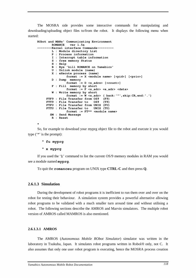
Yamabico Autonomous Mobile Robot Documentation 118
The MOSRA side provides some interactive commands for manipulating and
downloading/uploading object files to/from the robot. It displays the following menu when
started:
RObot and MANs' Communicating Environment ROMANCE ver 1.5a--------Kernel interface Commands--------- L : Module directory List P : Process information I : Interrupt table information S : free memory Status H : Help B : Bye 'kill ROMANCE on Yamabico' U : Unlink module (name) X : eXecute process (name) format := X <module name> [<pid>] [<prio>] D : Dump memory format := D <s_adrs> [<count>] F : Fill memory by short format := F <s_adr> <e_adr> <data> W : Write memory by short format := W <s_adr> ( back:'^',skip:CR,end:'.') FTF9 : File Transfer from OS9 (F9) FTT9 : File Transfer to OS9 (T9) FTFU : File Transfer from UNIX (FU) FTTU : File Transfer to UNIX (TU) format := FT** <module name> SM : Send Massage R : Reset
*
So, for example to download your myprg object file to the robot and execute it you would
type (‘*’ is the prompt):
* fu myprg
* x myprg
If you used the ‘l ’ command to list the current OS/9 memory modules in RAM you would
see a module named myprg .
To quit the romanceu program on UNIX type CTRL-C and then press Q.
2.6.1.3 Simulation
During the development of robot programs it is inefficient to run them over and over on the
robot for testing their behaviour. A simulation system provides a powerful alternative allowing
robot programs to be validated with a much smaller turn around time and without utilising a
robot. The following sections describe the AMROS and Marvin simulators. The multiple robot
version of AMROS called MAMROS is also mentioned.
2.6.1.3.1 AMROS
The AMROS (Autonomous Mobile RObot Simulator) simulator was written in the
laboratory in Tsukuba, Japan. It simulates robot programs written in Robol/0 only, not C. It
also assumes that only one user robot program is executing, hence the MOSRA process creation

Yamabico Autonomous Mobile Robot Documentation 119
calls cannot be used. It also assumes a Robol/0 WAIT loop executes every 50ms. The robot
program is compiled to run as a native process on the UNIX host. So the simulation is not quite
realistic. AMROS still provides a good idea of a robot program's behaviour. If your program
fails on AMROS it will surely fail on the real robot, but if it performs correctly on AMROS it
may perform correctly on the robot.
AMROS has also been extended to simulate Multiple robots. For information on Multiple
AMROS (MAMROS) refer to [Naum93].
Compiling
To compile your Robol/0 program for use with AMROS you need to use a UNIX host that
has the GNU gcc compiler installed43. Type the following:
robocc -sim myprg .rb0
This will compile the source program and produce an executable in your directory called
a.out . This executable includes the AMROS program and your robot program linked together.
Ensure your X Windows DISPLAY variable is set and execute a.out to run the simulation.
The simulator also has the ability to read in map files to represent the environment around the
robot. These are .vm files and are described in the following section. For example:
a.out -vm roboken91.vm
Would start AMROS with a map of Tsukuba's Roboken Laboratory as it was in 1991.
This assumes the map file is in the current directory. A full path may be specified.
Map files
The map files represent the environment as a simple 2D line drawing. The map can also
store information about the surface reflectivity for the ultrasonic sensors. The 2D line drawings
can be converted from the Interviews 3.1 IDraw drawing program files into map files using the
utility id2vm . The format of vm map files is detailed in an appendix.
2.6.1.3.2 Marvin
The Marvin (Multiple Autonomous Robot VIrtual eNvironment) simulator allows the
simulation of multiple Yamabico robot in realistic simulation time. It is modular in construction
so that sensor and actuator simulation can be added incrementally.
Marvin is still under development in the Wollongong Laboratory. Refer to Marvin
documentation.
43In the Wollongong laboratory use the 'Terumi' machine.

Yamabico Autonomous Mobile Robot Documentation 120
2.6.1.4 Tools
2.6.1.4.1 Robocon
Robocon is a utility to allow the graphical editing of Robol/0 programs. It displays a
graphical representation of the Robol/0 action states and allows them to be manipulated using the
mouse and menu’s.
It is invoked as follows44:
robocon myprg.rb0
Note that robocon works by embedding information as comments into the Robol/0 source
code. Hence you should not edit these comments directly. Also the Robol/0 program must have
been initially created with robocon, otherwise the existing action modes will all be placed at the
same default location on the robocon display when robocon is used for the first time.
2.6.1.4.2 Roboemon
To be completed.
2.6.1.4.3 Robotra
To be completed.
2.6.1.5 Environment
This section details the environment that must be present on the UNIX host for the
software development tools to work correctly. This includes the appropriate installation
directories, necessary symbolic links, and environment variables.
To be completed.
44In the Wollongong laboratory use the ‘Terumi’ machine.

Yamabico Autonomous Mobile Robot Documentation 121
2.6.2 Building the Yamabico software
2.6.2.1 Compiling the MOSRA Kernel
To compile the MOSRA kernel for the master module or a function module follow these
steps:
1) Edit both the files Config.h and Config.a in the
../ys-kit/mosra/config directory. Just un-comment the line for the module
you wish to build.
2) Change to the ../ys-kit/mosra/kernel directory and type:
make -f Makefile.sun all
This produces a file called mosra.rom in the ../kernel/objs directory. It consists
of some boot code to get the board started and an OS/9 format object module called mosra68k
which is the kernel code. Since the 68000 CPU requires the start of execution vector to in low
memory and the Yamabico ROM’s typically map into higher memory, the boards contain a
circuit that temporarily maps the ROM to address 0 upon reset. So the boot code contains the
initial execution address. The mosra.rom file is the minimum required to make a ROM to
execute MOSRA. When started MOSRA will look for a module named startup , and if found
will mfork() it. Typically startup will fork any required modules and then exit (with
death() ).
2.6.2.2 Making a Master Module ROM image
A simple master module ROM image would consist of the MOSRA kernel image, a startup
module which mfork() ’s TIMER and ROMANCE, the timer module and the romance
module. Other modules may be included in the ROM image as desired. Because MOSRA
locates the memory module’s by searching memory for them (they begin with a special magic
number $4afc), modules may be added to the ROM by simple concatenation. There are a number
of different master module configurations represented by subdirectories of
../ys-kit/module beginning with mm. Suppose we wish to build mmW45. Follow these
steps:
1) Build the MOSRA kernel as described in the last section, remembering to configure for
the required master module.
2) Change to the ../ys-kit/module/mmW directory and type:
make -f Makefile.sun all
45 The standard master module used by the typical Yamabico is mmKEI. mmW is a modification of mmKEI used
in Wollongong that adds the Radio Modem Network (RAD NET) and some minor kernel modifications.

Yamabico Autonomous Mobile Robot Documentation 122
3) Change to the ../ys-kit/module/mmW/rom directory and type: cp.mosra
This copies the MOSRA kernel image built in step 1 and the romance module into the
file mosra.mmW
4) Type make.rom
This copies the mosra.mmW, startup module, network module, and timer
module into the final ROM image file rom.mmW.
Next the ROM image rom.mmW can be programmed using a ROM programmer. Note
that since the ROM is built for a 68000 CPU which has a 16Bit data bus, the ROM will be
16bits wide. This means that the computer driving a ROM programmer must interpret the image
as a stream of 16bit words (pairs of bytes). So the CPU of the computer driving the ROM
programmer must be of the same endian as the 68000 or the ROM image file must have the
endian reversed by swapping byte pairs (for example if the ROM programmer was connected to
an Intel 80x86 based computer).
2.6.2.3 Compiling function module code
To be completed. Similar to above, but build an appropriate MOSRA kernel first, then
compile the function module code and build a ROM image.
2.6.2.4 Changing robot library code
All functions available to user robot programs come from a set of link libraries that are
linked with the final OS/9 executable module after compilation. In many cases these are simple
stubs that communicate with a function module via DPM or cause a TRAP to the kernel (for
system calls). The link libraries can be found in the ../local/os9/yamabico/lib
directory. Some of these libraries are concatenations of smaller libraries for specific parts of the
API. OS/9 library modules may be simply concatenated to form larger libraries (using the UNIX
cat command for example).
The procedure for updating or modifying a library function is best illustrated with an
example. The example will show how to modify the us_dist() command that obtains a
distance range reading from an ultrasonic sensor.
The implementation of the HiSonic library code can be found in the directory ../ys-
kit/module/HiSonic/lib . The function we wish to modify is in the file us_dist.c .
Suppose we have modified the function, now from the directory re-compile to generate the new
libSONic.l link library by using the command make -f Makefile.sun . Once this is
complete change into the directory ../ys-kit/ground/install and type makelib to
execute the makelib script file. This script concatenates all the link libraries from the various
module directories into the ymbclib.l link library that is linked into user programs from the
lib directory. If you wish to actually add another link library to this, modify the script. This is

Yamabico Autonomous Mobile Robot Documentation 123
not necessary for this example. This takes care of the modification to the us_dist()
implementation, and may be all you wished to do.
If in addition to change the implementation you also wished to add some extra definitions
or declarations that the user programs will require, you will also need to update the
HiSonic_usr.h header file that is included into user programs from the defs directory
(../local/os9/yamabico/defs/ymbc ). You should not edit this file directly as there
are two copies of these header files. The original source is usually kept in the module defs
directory. Change into the directory ../ys-kit/module/HiSonic/defs where you will
find the correct HiSonic_usr.h header to edit. Now this modified header should be updated
into the OS/9 defs directory. This is also achieved using a script from the
../ys-kit/ground/install directory as with updating the library. Change to this
directory and execute the makedefs script. This will copy all the header files from their
respective module defs directories into the OS/9 defs directory. That completes necessary the
changes. Of course user programs will need to be re-compiled and re-linked to use the updated
version of the library function.

Yamabico Autonomous Mobile Robot Documentation 124
2.7 Implementation of a Robot Simulator
This section discusses the implementation of the AMROS and Marvin robot simulators.
Specifically what follows is a brief overview and comparison of how the robot function module
and master module code interacts in three contexts: a Yamabico robot, the AMROS simulator and
the Marvin simulator. Then some aspects of the implementation of AMROS and Marvin are
discussed.
2.7.1 Overview of Yamabico architecture
The Yamabico robots consist of a collection of single board computers interconnected by a
bus (the Yamabico II bus). One of the CPU boards is named the master module and it
conceptually directs the functions of the remaining function modules. The function modules
typically implement the function of a particular sensor or actuator system, while the master
module executes user level code to implement the higher level behaviour of the robot.
On the Yamabico robots, each of the module boards runs an operating system called
MOSRA. The user programs that run on the master module have an number of API sets available
to them. Specifically, the MOSRA system call API, which is implemented by linking stub
routines with the user code, which cause a software TRAP #0 which is then vectored to the
MOSRA system call dispatch code. The API sets for accessing each of the function modules are
implemented using a set of stub routines which read and write a Dual Port Memory (DPM) on
the appropriate function module. A write causes an interrupt on the function module CPU board
which then triggers the appropriate action. If the user function being called only requires current
state information, often the DPM is asynchronously read from the master module without the
intervention of the function module, which is just required to periodically update the state
information in the DPM. This concept is called a State Information Monitoring Panel (SIMP).
As is the case with the Spur locomotion module, function module code is often largely
interrupt driven, being tied closely with the robot hardware. See section 2.5 for a detailed
explanation of the communication between Spur and the master module. The locomotion
algorithms implemented on the Spur locomotion module are driven by interrupts from the
hardware and from a timer device that delivers interrupts every 5ms. The algorithms use
feedback from the motors and wheel encoders to adjust the motor currents based on the current
tracking mode. The tracking mode is only modified by master module commands as issued from
user program code. The mode is modified when an interrupt is received from the DPM in
response to a write from the master module.
The are a number of ways to implement the simulation of these hardware and software
components of a robot.

Yamabico Autonomous Mobile Robot Documentation 125
Execute the module software on the host operating system
The software that is normally compiled for the robot CPU target can be re-compiled to
run directly on the simulation host system. This is the approach taken by AMROS. The user
program is run directly under UNIX. A link library is provided that matches the API of the
library of routines available under the robot environment. These routines call functions in the
simulator that interact with a representation of the robot’s simulated environment.
Simulate the robot module at a hardware level
The CPU and hardware of the robot can be simulated on the host. The code compiled
for the robot target can then be interpreted and any memory accesses to hardware trapped and
simulated. The interaction with the simulated environment is then via the simulated sensor
and actuator hardware.
A hybrid of the above two approaches
Alternatively a combination of these approaches can be taken. This is the approach
taken by the Marvin simulator. Marvin interprets the user code targeted for the robot. The
MOSRA operating system, however, is not simulated in the current version. Any user code
system calls or function module commands can be caught by intercepting TRAP #0
instructions, or accesses to the DPM addresses. The code that normally executes on the Spur
locomotion module is executed directly on the UNIX host as in AMROS. The code that
normally executes on the ultrasonic function module is not executed at all, but the
functionality is simulated directly.
2.7.2 AMROS Implementation
The source code for AMROS is located in the ../ams-kit directory. Under this
directory you will find ys-amros which a duplication of the robot source code from ../ys-
kit that will now run directly on the UNIX host. Also there is an amros directory that
contains source code for simulation of the robot’s environment and gluing the user code with the
simulator. AMROS imposes a few restrictions on user robot code to be simulated. Specifically,
it assumes that only one user process is executed on the robot and that many MOSRA system
calls are not used. The only MOSRA system calls implemented for simulation are the
malloc() and mfree() memory management calls and the death() call. No process,
interrupt, memory module management46 or interprocess communication calls may be used. This
is typical of user robot code.
46 AMROS does construct a module directory and implements the MOSRA module API calls by maintaining
created modules as standard UNIX files. This facility may not be properly supported in the current version and is
rarely used in practice. See the ../ams-kit/amros/mosra.c file.

Yamabico Autonomous Mobile Robot Documentation 126
2.7.2.1 Implementation of user calls
The next few sections detail how particular user functions available in the robot target
environment are implemented when user code is executing on the UNIX host environment linked
with AMROS.
The malloc() and mfree() MOSRA calls
In the robot environment the function stubs that are linked with the user code for these two
functions cause a TRAP #0 with the appropriate code so that MOSRA will dispatch to it’s
implementation the functions. When the user code is instead linked with AMROS the functions
are implemented to simply call the equivalent UNIX malloc() and free() functions47. This
means that the simulation places no restrictions on memory usage by user robot code, as it is
allocated from the UNIX process’s heap space.
The readSRTKEI() and compSRTKEI() calls
These functions are implemented on the robot by simply reading the current value of the
free running timer chip hardware. AMROS implements them in ../ams-kit/ys-
amros/ymbclib/srt.c by accessing the global function get_timer6840() which
returns a 10ms interval count by accessing the global variable t2 which is incremented by the
environment simulation. See the ../ams-kit/amros/main.c file.
The set_timer() and timer_wait() calls
These are implemented on the robot by using the MOSRA inter-process communication
calls to send a message to the TIMER module process. AMROS implements them by again
accessing the global simulation time counter (global variable t ) via the CLKget_time()
function. The implementation is contained in the file
../ams-kit/amros/ymbcfuncs.c.
The death() function
This is the only process management MOSRA system call implemented. On the robot is
terminates the current process and frees it’s static data area and process descriptor. Under
AMROS the implementation ends the simulation.
47 Since the UNIX memory allocation function has the same name as the MOSRA one (malloc() ), the function
is not redefined by AMROS. AMROS only implements mfree() to call the UNIX free() function.

Yamabico Autonomous Mobile Robot Documentation 127
The write_cons() and read_cons() ROMANCE functions
These two functions are implemented on the robot with link library stubs that use inter-
process communication to communicate with the ROMANCE module process. This process in
turn uses the serial interface to communicate with the user on the UNIX host. Under AMROS
these functions simply call C standard library printf() and scanf() .
2.7.2.1.1 The UltraSonic module API calls
The HiSonic ultrasonic module is more difficult to simulate. AMROS has adopted a ray
line model, where for each firing of the simulated sensor, a fan of rays within -10o - +10o of the
sensor direction are traced out until they intersect a surface in the 2D map. The 2D map files
contain reflectance and diffusivity data for each surface, which is used to calculate the reflected
rays. If the rays eventually reflect back into the sensor, the length of the traced ray is used as the
measure of the distance the sensor detects.
The user program on the robot calls the us_dist() and us_mask() functions to
obtain range data and select the sensors. These functions just read and write the DPM on the
HiSonic board. The AMROS implementation for the functions is located in the ../ams-
kit/amros/sensor.c file. It directly implements the ray algorithm by accessing the map
data structures.
2.7.2.1.2 The Locomotion module Spur API calls
Rather than simulating the locomotion of the robot at a high level as was the case with the
ultrasonic sensor simulation, the approach taken is to execute the code that normally executes on
the robot’s locomotion function module board directly on the UNIX host. The motor and wheel
encoder hardware is then simulated and interacts with the Spur locomotion software. Please refer
back to the diagram at the end of the Spur implementation section for a summary of how Spur
works in the robot environment (section 2.3.3.2). The diagram below shows how Spur is
executed in AMROS. Compare it with the robot case.

Yamabico Autonomous Mobile Robot Documentation 128
AMROS
Call
User Robol/0 program linked with AMROS...Spur_line_GL(0,0,0)
send_com16()
dpm = command & srgs
...
Spur_get_pos_GL(&x,&y,&th)
rd_SIP()
x = dpm *...
dpm_irq()
com_ana()
cmode = dpm *tim_irq()
fb_ctl()
cal_r_vel()
wt_SIP()
dpm* = Spur state
mode_ctl()
switch (cmode.mode)
do_ line_track ()
pwm* -> ... = ...count = cnt * [M_xx ]
dpm_irq()
Robol0_main()
main()
amros_simulate()
LOCOsim(50ms)
robot_motion()
*shared global variables
... = pwm* ; cnt * [] = ...
AMROS software implementation

Yamabico Autonomous Mobile Robot Documentation 129
2.7.3 Marvin Implementation
The Marvin simulator is designed to simulate multiple robots more realistically that
AMROS. It removes some of the restrictions such as only simulating Robol/0, and only allowing
a single user process per robot48. Marvin uses an interpreter to execute the Motorola 68000
machine code that executed on the robot itself. Hence it is binary compatible with the robot. A
single UNIX process is created for each robot being simulated. These each run a copy of the
interpreter an communicate with the main Marvin process using Sockets. The main process
manages the user interface, represents the environment and manages the communications between
robots. The environment representation is object-oriented and is 3D. This will allow extra
sensor simulations to be added in a modular fashion in the future49. Marvin uses some of the
locomotion and ultrasonic sensor simulation code from AMROS.
2.7.3.1 Implementation of user calls
The next few sections detail how particular user functions available in the robot target
environment are implemented when user code is executing under the Marvin interpreter. In the
current version of Marvin any MOSRA system calls have to be caught by intercepting the TRAP
#0 instruction and simulated. In a future version the operating system executing on the robot
master module (MOSRA) will execute under the interpreter.
The malloc() and mfree() MOSRA calls
In Marvin the malloc() and mfree() system calls are caught through TRAP #0 and
implemented on the simulated memory array using the MOSRA algorithms.
The readSRTKEI() and compSRTKEI() calls
These functions are implemented under Marvin by catching memory read/write accesses to
the address of the timer chip hardware. The appropriate time it returned based in the number of
clock cycles elapsed, which is counted by the interpreter.
The set_timer() and timer_wait() calls
Marvin intercepts these calls by intercepting the MOSRA send_mess() system call.
It then checks the destination process ID (pid). If the pid is that of the TIMER process then the
calls are simulated.
48The first implementation of Marvin will only allow a single user process per robot, and will not run MOSRA.
Hence not all the MOSRA system calls are available.
49It is hoped that vision simulation will be added in the next year.

Yamabico Autonomous Mobile Robot Documentation 130
The death() function
The death() function sends a terminate message to the main process and ends the
interpreter.
The write_cons() and read_cons() ROMANCE functions
The console I/O calls are handled in a similar way to the timer calls. The user program
sends I/O requests to the ROMANCE process using the MOSRA send_mess() system call. It
is intercepted and if the process ID is that of romance then a message is sent to the main Marvin
process to input or output to either standard I/O or a robot window.
2.7.3.1.1 The UltraSonic module API calls
Marvin uses the AMROS ray model to simulate the ultrasonic sensors. The difference is
that the environment is represented in 3D in Marvin. The user program on the robot calls the
us_dist() and us_mask() functions to obtain range data and select the sensors. These
functions just read and write the DPM on the HiSonic board. Under Marvin the interpreter can
detect and intercept memory accesses to the HiSonic DPM area. It then sends the appropriate
messages to the main process where the ray model algorithm is implemented with the environment
representation.
2.7.3.1.2 The Locomotion module Spur API calls
Again, Marvin uses the code from AMROS to simulate the locomotion. Both the Spur
software that normally executes on the locomotion board and the environment simulation of
motors and wheel encoders execute on the main Marvin process. User program Spur calls just
read and write to the locomotion DPM, which is intercepted by the interpreter and the command,
arguments and results are communicated with the main process via the sockets. The diagram
below shows the architecture of Marvin executing a single robot’s code.
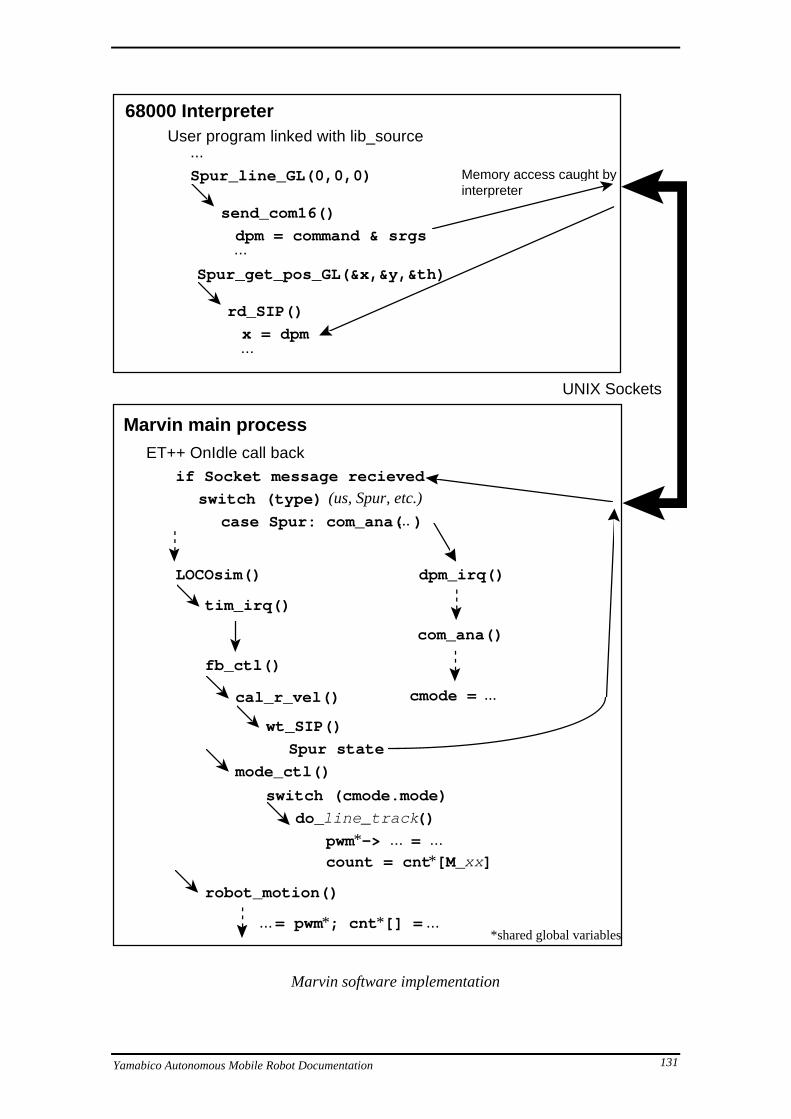
Yamabico Autonomous Mobile Robot Documentation 131
UNIX Sockets
68000 Interpreter
Marvin main process
User program linked with lib_source...Spur_line_GL(0,0,0)
send_com16()
dpm = command & srgs...
Spur_get_pos_GL(&x,&y,&th)
rd_SIP()
x = dpm...
dpm_irq()
com_ana()
cmode = ...
Memory access caught by interpreter
ET++ OnIdle call backif Socket message recieved
switch (type) (us, Spur, etc.)
case Spur: com_ana( ... )
tim_irq()
fb_ctl()
cal_r_vel()
wt_SIP()
Spur state
mode_ctl()
switch (cmode.mode)
do_ line_track ()
pwm* -> ... = ...count = cnt * [M_xx ]
LOCOsim()
robot_motion()
*shared global variables... = pwm* ; cnt * [] = ...
Marvin software implementation

Yamabico Autonomous Mobile Robot Documentation 132
2.7.3.2 Marvin multi-robot synchronisation scheme
This section briefly describes the protocol by which Marvin manages the simulation-time
synchronisation of multiple robot interpreter processes. As the user code on each robot is
simulated independently of the others and of the environment by an interpreter, we need to have a
mechanism to manage the synchronisation of their interaction. Consider the following example.
Suppose robot 1 runs it’s user program for 10 seconds with no interaction with the
environment. Then at 10 seconds it decides to read an ultrasonic sensor. At this point the
blackboard needs to simulate the environment up to the 10 second mark before calculating the
ultrasonic distance. This involves simulating the locomotion etc. of all of the robots up to 10
seconds. If this were not done, another robot may not be in the correct place when the distance
reading is taken (it could be in front of robot 1’s sensor, for example). Unfortunately it is not as
simple as just advancing the environment simulation up to 10 seconds, because is may be that
another robot, say robot 2, will take a sensor reading at 5 seconds, but the interpreter for it is
running so slow it’s only currently up to 3 seconds and hence has not requested the reading from
the blackboard yet. If when it gets to 3 seconds and requests a reading from the blackboard and
the environment had already been advanced to 10 seconds the reading would be incorrectly from
the robot’s future.
The solution to this problem used by Marvin is to use the protocol described here, briefly
at first and then in more detail with pseudo code. Basically the simulation is started with all of
the robots executing and keeping their own independent simulation time count. When a robot
wishes to perform a sensor or actuator command it sends a message to the blackboard process. If
results are to be returned, the interpreter is halted, only monitoring messages from the
blackboard. If no results are needed the interpreter continues on. The blackboard maintains a
sorted queue of requests for ‘sensor/actuator commands’ received from the robots. Upon
receiving a command message the blackboard adds it to the queue sorted on the time the
command was issued. It then sends requests to each robot except the originator of the command
message, requesting that they ‘simulate up-to’ at least the time the originator’s command was
issued. It also stores an indication that each robot has replied to the requests. Only after all
robots have replied to the ‘simulate up-to’ request can the environment be simulated up to this
time. However, as a result of the other robot processes simulating up-to the requested time, if
they were not past it already, they may have sent further ‘sensor/actuator command’ requests to
the blackboard of an earlier time. In this case the same procedure is followed when these are
received. When all replied have been received for the message on the queue with the earliest time
(since earlier ‘sensor/actuator command’ requests may have been received), the environment may
be advanced to this time and the command removed from the queue.
The robot processes only have to keep a sorted list of the ‘simulate up-to’ request times
they have been requested to simulate up to by the blackboard, so they can reply to each as their
simulation time advances past them. The robot processes always continue to simulate unless
waiting for data to be returned from a sensor command.
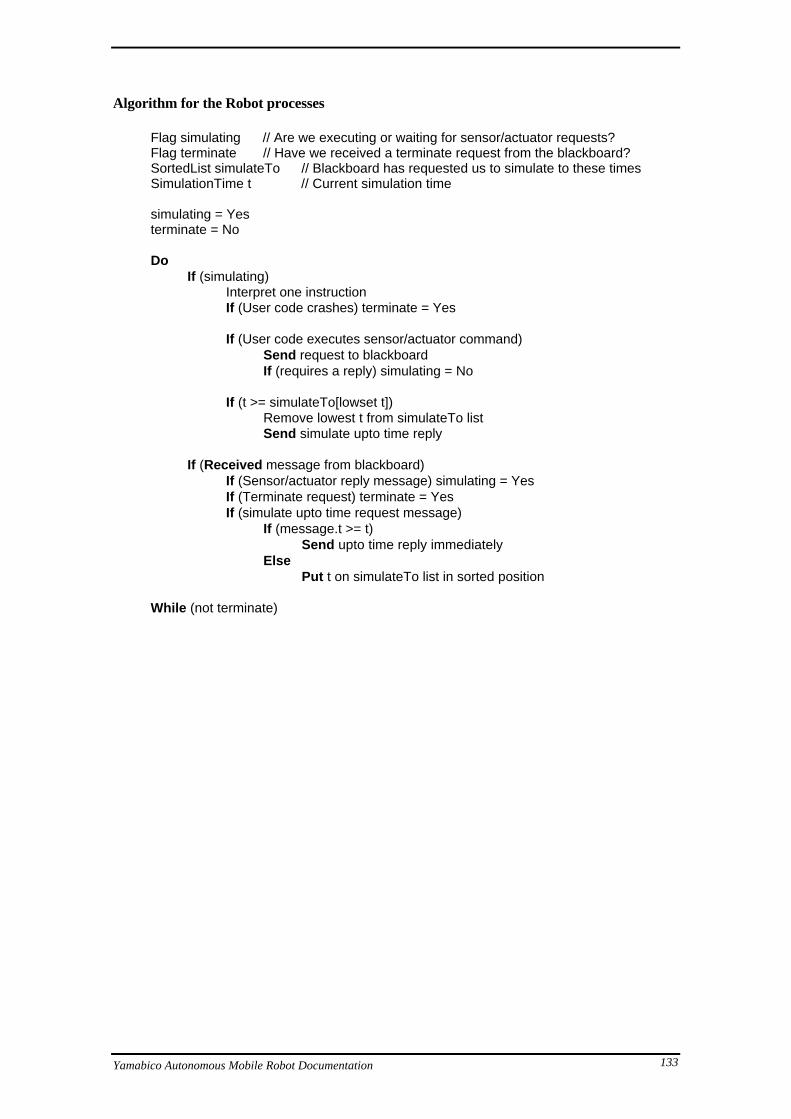
Yamabico Autonomous Mobile Robot Documentation 133
Algorithm for the Robot processes
Flag simulating // Are we executing or waiting for sensor/actuator requests?Flag terminate // Have we received a terminate request from the blackboard?SortedList simulateTo // Blackboard has requested us to simulate to these timesSimulationTime t // Current simulation time
simulating = Yesterminate = No
DoIf (simulating)
Interpret one instructionIf (User code crashes) terminate = Yes
If (User code executes sensor/actuator command)Send request to blackboardIf (requires a reply) simulating = No
If (t >= simulateTo[lowset t])Remove lowest t from simulateTo listSend simulate upto time reply
If (Received message from blackboard)If (Sensor/actuator reply message) simulating = YesIf (Terminate request) terminate = YesIf (simulate upto time request message)
If (message.t >= t)Send upto time reply immediately
ElsePut t on simulateTo list in sorted position
While (not terminate)

Yamabico Autonomous Mobile Robot Documentation 134
Algorithm for Main Process (Blackboard)
The main Marvin process is also responsible for implementing the Graphical User
Interface (GUI). The GUI is implemented using the ET++ framework. The socket
communications between the main and robot processes was implemented with the socket++
framework. In order to integrate the input models of ET++ and socket++ it was necessary to
implement the main processing of the blackboard inside the ET++ OnIdle call-back.
Type CommandType is {CommandMessage messageTime timeRobot fromRobotArray of Flags uptoTimeReplied[1..NoRobots]
}
SortedList of CommandType commands // Queue of commands to be processedSimulationTime t // Current simulation time
OnIdle:If (Robot message received)
switch (message type)case (sensor/actuator command):
Add message to commands[] in sorted order by message.timeSend simulate uptoTime request messages to all robots*command.uptoTimeReplied[1..NoRobots] = No*
(*except SendingRobot, and except if a robot alreadyreplied to a future uptoTime request)
case (simulate uptoTime reply FromRobot):commands[].uptoTimeReplied[FromRobot] = Yes
If (commands[lowest time].uptoTimeReplied[1..NoRobots] all Yes)Simulate environment
(for 100ms or up to commands[lowest time].time,whichever is sooner)
If (t >= commands[lowest time].time)Process sensor/actuator command commands[lowest time].messageRemove commands[lowest time] command from list

Yamabico Autonomous Mobile Robot Documentation 135
3. Appendices
3.1 Appendix A - API Prototype Reference
This appendix summarises the API’s of MOSRA and some function modules. The
function call prototypes are listed below.
3.1.1 MOSRA
Process Control functions int mfork(char *mname,int pid,int priority); int pcreate(MOD_EXEC *mod_address,int pid,int priority); int death(); int sleep(); int wakeup(int pid); int getpid(); char *get_work();
Interrupt Handling & Exception functions int irqtbl(int level,IRQTBL *table); int irqdel(int level,IRQTBL *table); int irqctl(int pid,int level); int exsect(); int exend(); int irqset(int level); int irqrst();
Interprocess Communication functions int send_mess(int pid,char *mes_p); void *recv_mess(int pid); int test_mess(int pid);
Memory Allocation functions void *malloc(int size); int mfree(void *address);
Memory Module functions int ismod(void *m_adr); MOD_DATA *make_mod(char *mname,int size); int crcgen(MOD_DATA *m_adr); MOD_DATA *get_mod(char *mname); int regmod(MOD_DATA *m_adr); int delmod(MOD_DATA *m_adr);

Yamabico Autonomous Mobile Robot Documentation 136
3.1.2 Miscellaneous
ROMANCE console functions void write_cons(char *form_str,...); char *read_cons(char *form_str, char *data, int *count);
robocc option function void _report_am_name(char *name);
Simulator void amros_simulate(); void robol0_main();
3.1.3 Function Modules
US Sensor functions int us_dist(int dir); void us_mask(int mask_pattern);
Optical Sensor functions
IS eye functions void ISSUE_FORK(int p_name);
IS eye IAS process functions void IAS_thdist(int thdist[256]); void IAS_dist_cm(int i); void IAS_change_mode(int mode); int IAS_active_mode(); void IAS_ld_control(int ld_mode);
IS eye PaSS process functions PaSS_index PaSS_can_pass(PaSS_degree,PaSS_index); PaSS_index PaSS_free_pass(PaSS_degree,PaSS_index,PaSS_index); PaSS_degree PaSS_find_patchCL(PaSS_degree,PaSS_degree,PaSS_index,int); PaSS_degree PaSS_find_patchL(PaSS_degree,PaSS_degree,PaSS_index,int); PaSS_degree PaSS_find_patchCR(PaSS_degree,PaSS_degree,PaSS_index,int); PaSS_degree PaSS_find_patchR(PaSS_degree,PaSS_degree,PaSS_index,int); int PaSS_get_dy(PaSS_index,PaSS_degree); int PaSS_get_x(PaSS_index);
Spur functions void Spur_stop_q(); void Spur_stop_Q(); void Spur_spin_GL(int th); void Spur_spin_LC(int th); void Spur_spin_FS(int th); void Spur_set_ang_vel(int angv); void Spur_set_ang_accel(int alpha); void Spur_servo(); void Spur_servo_free(); int Spur_near_ang_GL(int ang,int error); int Spur_near_ang_LC(int ang,int error); int Spur_near_ang_vel(int angv,int error); void Spur_line_GL(int x,int y,int th); void Spur_line_LC(int x,int y,int th); void Spur_line_FS(int x,int y,int th);
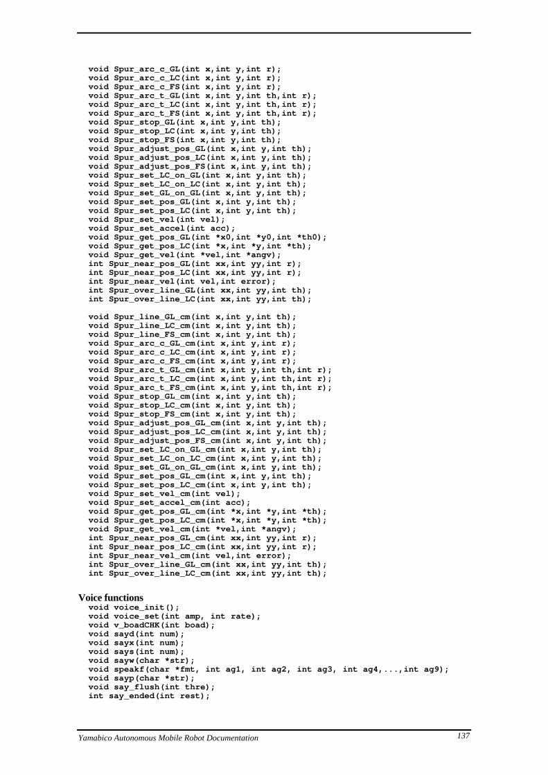
Yamabico Autonomous Mobile Robot Documentation 137
void Spur_arc_c_GL(int x,int y,int r); void Spur_arc_c_LC(int x,int y,int r); void Spur_arc_c_FS(int x,int y,int r); void Spur_arc_t_GL(int x,int y,int th,int r); void Spur_arc_t_LC(int x,int y,int th,int r); void Spur_arc_t_FS(int x,int y,int th,int r); void Spur_stop_GL(int x,int y,int th); void Spur_stop_LC(int x,int y,int th); void Spur_stop_FS(int x,int y,int th); void Spur_adjust_pos_GL(int x,int y,int th); void Spur_adjust_pos_LC(int x,int y,int th); void Spur_adjust_pos_FS(int x,int y,int th); void Spur_set_LC_on_GL(int x,int y,int th); void Spur_set_LC_on_LC(int x,int y,int th); void Spur_set_GL_on_GL(int x,int y,int th); void Spur_set_pos_GL(int x,int y,int th); void Spur_set_pos_LC(int x,int y,int th); void Spur_set_vel(int vel); void Spur_set_accel(int acc); void Spur_get_pos_GL(int *x0,int *y0,int *th0); void Spur_get_pos_LC(int *x,int *y,int *th); void Spur_get_vel(int *vel,int *angv); int Spur_near_pos_GL(int xx,int yy,int r); int Spur_near_pos_LC(int xx,int yy,int r); int Spur_near_vel(int vel,int error); int Spur_over_line_GL(int xx,int yy,int th); int Spur_over_line_LC(int xx,int yy,int th);
void Spur_line_GL_cm(int x,int y,int th); void Spur_line_LC_cm(int x,int y,int th); void Spur_line_FS_cm(int x,int y,int th); void Spur_arc_c_GL_cm(int x,int y,int r); void Spur_arc_c_LC_cm(int x,int y,int r); void Spur_arc_c_FS_cm(int x,int y,int r); void Spur_arc_t_GL_cm(int x,int y,int th,int r); void Spur_arc_t_LC_cm(int x,int y,int th,int r); void Spur_arc_t_FS_cm(int x,int y,int th,int r); void Spur_stop_GL_cm(int x,int y,int th); void Spur_stop_LC_cm(int x,int y,int th); void Spur_stop_FS_cm(int x,int y,int th); void Spur_adjust_pos_GL_cm(int x,int y,int th); void Spur_adjust_pos_LC_cm(int x,int y,int th); void Spur_adjust_pos_FS_cm(int x,int y,int th); void Spur_set_LC_on_GL_cm(int x,int y,int th); void Spur_set_LC_on_LC_cm(int x,int y,int th); void Spur_set_GL_on_GL_cm(int x,int y,int th); void Spur_set_pos_GL_cm(int x,int y,int th); void Spur_set_pos_LC_cm(int x,int y,int th); void Spur_set_vel_cm(int vel); void Spur_set_accel_cm(int acc); void Spur_get_pos_GL_cm(int *x,int *y,int *th); void Spur_get_pos_LC_cm(int *x,int *y,int *th); void Spur_get_vel_cm(int *vel,int *angv); int Spur_near_pos_GL_cm(int xx,int yy,int r); int Spur_near_pos_LC_cm(int xx,int yy,int r); int Spur_near_vel_cm(int vel,int error); int Spur_over_line_GL_cm(int xx,int yy,int th); int Spur_over_line_LC_cm(int xx,int yy,int th);
Voice functions void voice_init(); void voice_set(int amp, int rate); void v_boadCHK(int boad); void sayd(int num); void sayx(int num); void says(int num); void sayw(char *str); void speakf(char *fmt, int ag1, int ag2, int ag3, int ag4,...,int ag9); void sayp(char *str); void say_flush(int thre); int say_ended(int rest);

Yamabico Autonomous Mobile Robot Documentation 138
Timer functions void set_timer(int count); void timer_wait(); int readSRTKEI(); int compSRTKEI(int t0,int time);

Yamabico Autonomous Mobile Robot Documentation 139
3.2 Appendix B - AMROS Map file format
To be written.
3.3 Additional Information
3.3.1 Contacts
The authors of this document can be reached by e-mail at:
David Jung [email protected]
Ben Stanley [email protected]
Please contact us if you have any comments, find errors or have suggestions on content.
Also, Prof. Shin’ichi Yuta of the Tsukuba laboratory and Dr. Alex Zelinsky of the
Wollongong laboratory may be contacted at:
Prof. Shin’ichi Yuta [email protected]
Dr. Alex Zelinsky [email protected]
3.3.2 World Wide Web (WWW)
The Wollongong laboratory home page has the URL:
http://terumi.cs.uow.edu.au/
The Tsukuba Roboken laboratory home page is:
http://roboken.is.tsukuba.ac.jp/
or
http://130.158.125.241/
Yamabico Autonomous Mobile Robot Documentation 140
3.4 Bibliography
[Yam95] Yamabico Hardware documentation folder. Intelligent Robotics Laboratory,
1995. Mostly a direct translation from the Japanese version maintained by the
Tsukuba Laboratory.
[Iida91] Iida, Shigeki and Yuta, Shin’ichi “Vehicle Command System and Trajectory
Control for Autonomous Mobile Robots”, IROS 91, Nov. 3-5 1991, Osaka,
Japan. IEEE Cat. No. 91TH0375-6.
[Iida91A] Iida, Shigeki and Yuta Shin’ichi “Control of Vehicle with Power Wheeled
Steerings Using Feedforward Dynamics Compensation”, Proceedings IECON
91, pp 2264.
[Naum93] Naumovski, Jim, “MAMROS - A Multiple Autonomous Mobile Robot
Simulator”, Masters of Computer Science Thesis, University of Wollongong.
[Ohno95] Ohno, Takayuki, Ohya, Akihisa and Yuta, Shin’ichi, “An Improved Sensory
Circuit of an Ultrasonic Range Finder for Mobile Robot’s Obstacle Detection”,
Proceedings of the 1995 National Conference of the Australian Robot Association,
Melbourne, 5-7 July. pp 178.

Yamabico Autonomous Mobile Robot Documentation 141
3.5 Document History
Date Author Comment
10/2/95 David Jung Created initial document, version 0.x
Documented Software Section
19/5/95 Ben Stanley Re-format to MS-Word 6.0 for Windows, added some parts
on hardware.
Ben Stanley Converted back to Word for the Mac.
27/6/95 David Jung Fixed formatting lost in conversion.
28/6/95 David Jung Documented more API calls.
10/7/95 Ben Stanley Split document into Hardware and Software files.
10/7/95 David Jung More format fixes. Filled out section on Software
Development.
11/7/95 David Jung Described directory structure. Added MAMROS section.
12/7/95 Ben Stanley Accidentally deleted software documentation!
13/7/95 David Jung Re-wrote section on Software development and Simulation.
14/7/95 David Jung Re-wrote and finished Spur API.
2/8/95 David Jung Added MOSRA Examples.
8/8/95 David Jung Added more Examples. Corrections.
26/8/95 David Jung Described MOSRA system calls.
28/8/95 David Jung Added section 2.4 Inter-module communication.
5/9/95 David Jung Added Spur examples/diagrams.
12/9/95 David Jung Documented ROMANCE console implementation, voice
API, and locomotion implementation.
13/9/95 David Jung Documented MOSRA interrupt API, cleaned up Hardware
section styles.
13/9/95 Ben Stanley Cleaned up and added to Hardware section.
14/9/95 Release 1.0
1/10/95 David Jung Added AMROS and Marvin implementation notes.
6/10/95 David Jung Converted to Word 6.0 and made master document, cleaned
up styles, headers, footers etc.
6/10/95 David Jung Filled out building ROM’s section.
7/10/95 David Jung Finished MOSRA & timer function implementation notes.
8/10/95 Release 1.1
10/5/96 David Jung Corrections to module API and sleep() , wakeup() .
2/7/96 David Jung Documented RADNET Networking.
6/7/96 David Jung Documented Threads, Semaphores and Whiskers API’s.
10/7/96 Release 1.5