y. kadi cern, switzerland 16 march 2011, isolde seminar, cern accident at fukushima daiichi nuclear...
TRANSCRIPT

Y. KadiCERN, Switzerland
16 March 2011, ISOLDE Seminar, CERN
Accident at Fukushima Daiichi Nuclear Power Station

Y. Kadi 2
CHALLENGE FOR THE MANKIND!
Mar.16 2011, ISOLDE Seminar

Y. Kadi 3
A NEW PRIMARY ENERGY SOURCE
By 2050, the world’s consumption (+ 2%/y) should reach 34 TW, of which 20 TW should come from new energy sources: A major innovation is needed in order to replace the expected “decay” of the traditional energy sources!
This implies a strong R&D effort, which is the only hope to solve the energy problem on the long term. This R&D should not exclude any direction a priori!* Renewables* Nuclear (fission and fusion)* Use of hydrogen
Can nuclear energy play a major role?
Nuclear energy has the potential to satisfy the demand for a long time (at least 15 centuries for fission, essentially infinite for fusion if it ever works), and is obviously appealing from the point of view of atmospheric emissions.
Mar.16 2011, ISOLDE Seminar

Y. Kadi 4
NUCLEAR FLEET WORLDWIDE
34 units are under construction
Mar.16 2011, ISOLDE Seminar
Y. Kadi 5
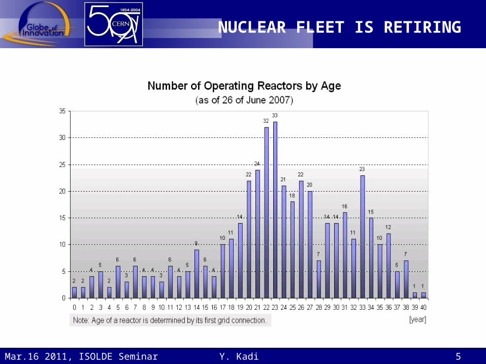
NUCLEAR FLEET IS RETIRING
Mar.16 2011, ISOLDE Seminar

Y. Kadi 6
DEVELOPMENT IS TIME- CONSUMING
Mar.16 2011, ISOLDE Seminar
Y. Kadi 7
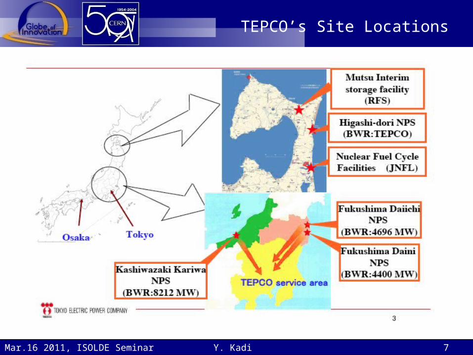
TEPCO’s Site Locations
Mar.16 2011, ISOLDE Seminar

Y. Kadi 8
Fukushima Daiichi NPP
Mar.16 2011, ISOLDE Seminar

Y. Kadi 9
Fukushima Daiichi NPP
Mar.16 2011, ISOLDE Seminar
Y. Kadi 10
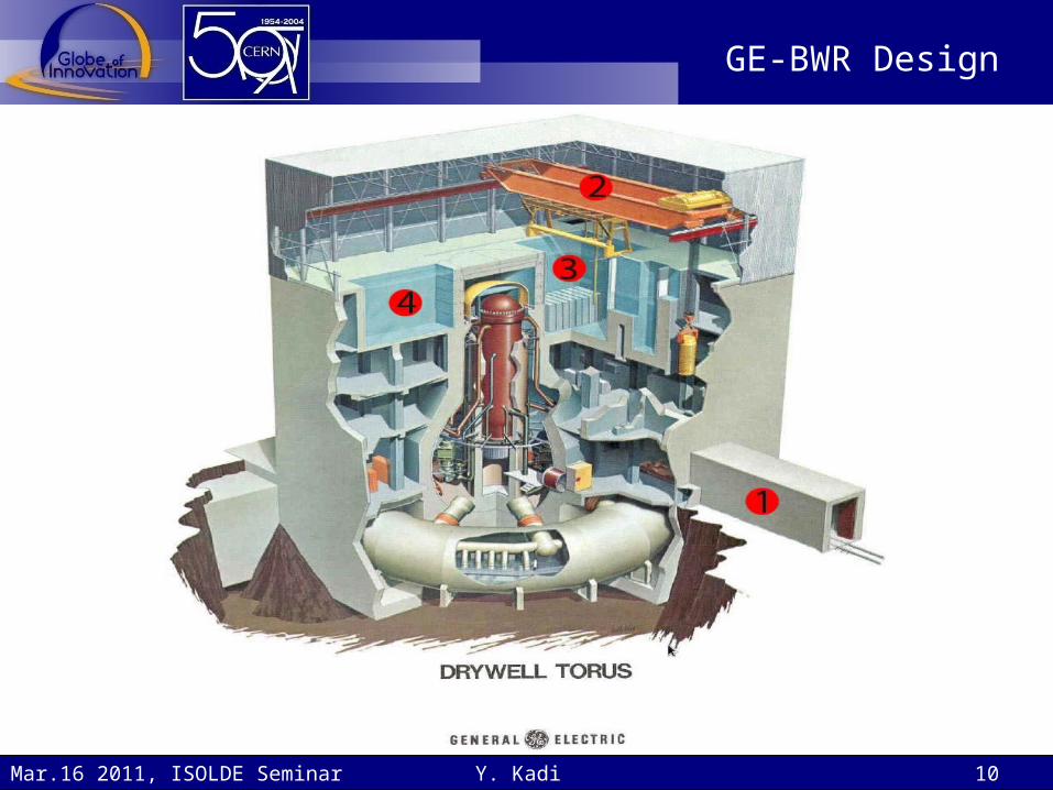
GE-BWR Design
Mar.16 2011, ISOLDE Seminar

Y. Kadi 11
GE-BWR Principle
Mar.16 2011, ISOLDE Seminar

Y. Kadi 12
GE/Hitachi current fleet of BWRs
BWRs are ideally suited for peaceful uses like power generation, process/industrial/district heating, and desalinization, due to low cost, simplicity, and safety focus, which come at the expense of larger size and slightly lower thermal efficiency.
• Sweden is standardized mainly on BWRs.
• Germany has a large number of BWRs, most of which are to
be decommissioned after the Fukushima accident.
• Mexico's only two reactors are BWRs.
• Japan experimented with both PWRs and BWRs, but most
builds as of late have been of BWRs, specifically ABWRs.
Mar.16 2011, ISOLDE Seminar

Physical Barriers / Levels of Protection
Y. Kadi 13Mar.16 2011, ISOLDE Seminar
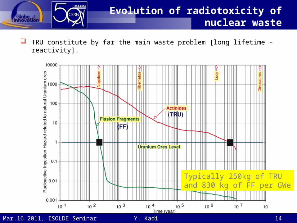
Evolution of radiotoxicity of nuclear waste
TRU constitute by far the main waste problem [long lifetime – reactivity].
Typically 250kg of TRU and 830 kg of FF per GWe
Y. Kadi 14Mar.16 2011, ISOLDE Seminar

Radioactive Decay of Fission Products (1)
Y. Kadi 15Mar.16 2011, ISOLDE Seminar

Radioactive Decay of Fission Products (2)
Y. Kadi 16
• Approximate reactor decay heat vs. time. The curves begin after the SCRAM of the reactors (complete and rapid control rod insertion) that occurred immediately after the earthquake.
• If the decay heat is not removed then the reactor fuel begins to heat up and undesirable consequences begin as the temperature rises such as rapid oxidation of the zircaloy cladding (~1200C), melting of the cladding (~1850C), and then the fuel (~2400-2860C).
Mar.16 2011, ISOLDE Seminar

Y. Kadi 17Mar.16 2011, ISOLDE Seminar
Explanation of Hydrogen Explosions at Units 1 and 3
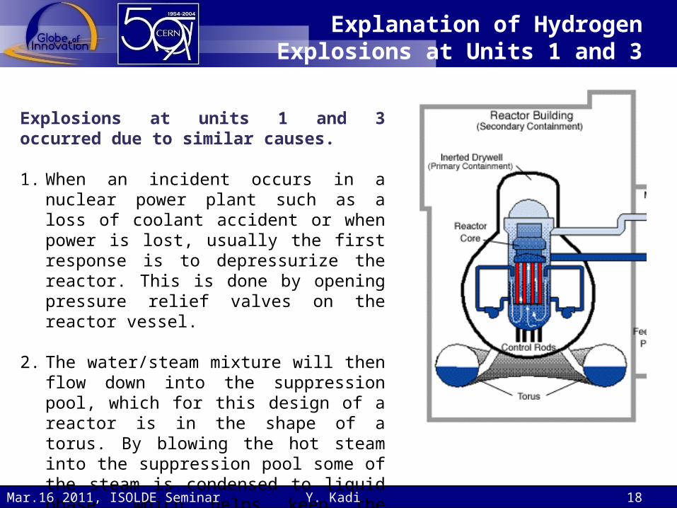
Explosions at units 1 and 3 occurred due to similar causes.
1. When an incident occurs in a nuclear power plant such as a loss of coolant accident or when power is lost, usually the first response is to depressurize the reactor. This is done by opening pressure relief valves on the reactor vessel.
2. The water/steam mixture will then flow down into the suppression pool, which for this design of a reactor is in the shape of a torus. By blowing the hot steam into the suppression pool some of the steam is condensed to liquid phase, which helps keep the pressure low in the containment.
Y. Kadi 18Mar.16 2011, ISOLDE Seminar

Explanation of Hydrogen Explosions at Units 1 and 3
3. The pressure in the reactor vessel is reduced by venting the water/steam mixture. It is much easier to pump water into the vessel when it is at a reduced pressure, thus making it easier to keep the fuel cooled.
4. This procedure was well underway after the earthquake. Unfortunately, because of the enormous magnitude of the earthquake, an equally large tsunami was created.
5. This tsunami disabled the onsite diesel generators as well as the electrical switchyard. Without power to run pumps and remove heat, the temperature of the water in the reactor vessel began to rise.
Y. Kadi 19Mar.16 2011, ISOLDE Seminar
Explanation of Hydrogen Explosions at Units 1 and 3
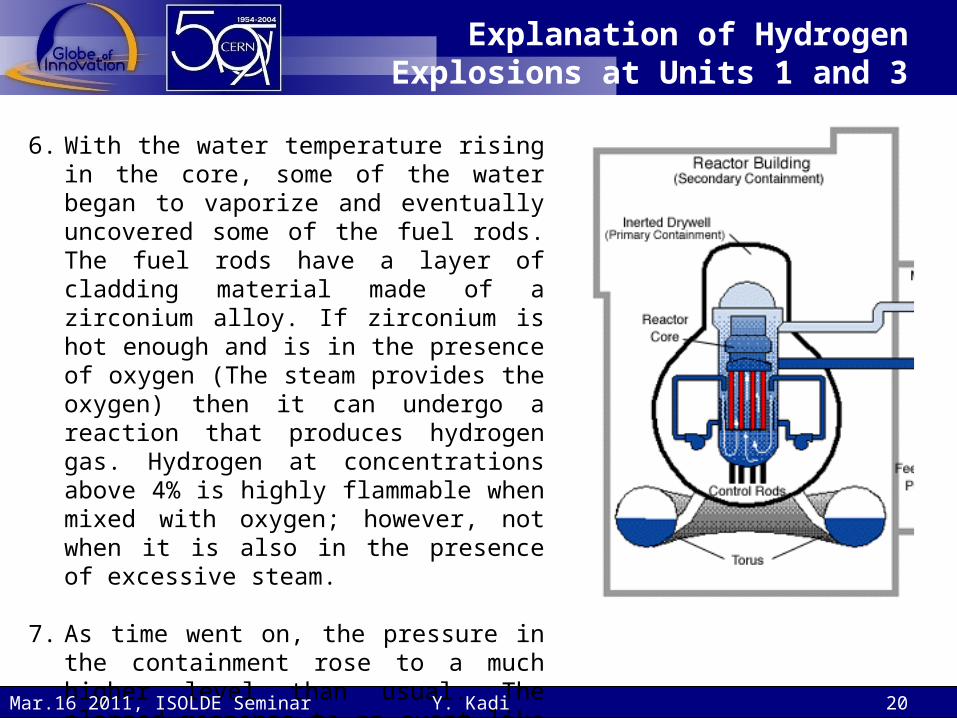
6. With the water temperature rising in the core, some of the water began to vaporize and eventually uncovered some of the fuel rods. The fuel rods have a layer of cladding material made of a zirconium alloy. If zirconium is hot enough and is in the presence of oxygen (The steam provides the oxygen) then it can undergo a reaction that produces hydrogen gas. Hydrogen at concentrations above 4% is highly flammable when mixed with oxygen; however, not when it is also in the presence of excessive steam.
7. As time went on, the pressure in the containment rose to a much higher level than usual. The planned response to an event like this is to vent some of the steam to the atmosphere, just to keep the pressure under control.
Y. Kadi 20Mar.16 2011, ISOLDE Seminar

Explanation of Hydrogen Explosions at Units 1 and 3
8. It was decided to vent the steam through some piping that led to a space above and outside containment, but inside the reactor building. At this point, the steam and hydrogen gas were mixed with the air in the top of the reactor building.
9. This was still not an explosive mixture because large amounts of steam were mixed with the hydrogen and oxygen (from the air). However, the top of this building is significantly colder than inside the containment due to the weather outside. This situation would lead to some of the steam condensing to water, thereby concentrating the hydrogen and air mixture.
10.This likely went on for an extended period of time, and at some point an ignition source (such as a spark from powered equipment) set off the explosion that was seen in units 1 and 3. The top of the reactor building was severely damaged; however, the containment structure showed no signs of damage.
Y. Kadi 21Mar.16 2011, ISOLDE Seminar

Unit 2 Explosion
The explosion at Unit 2 of the Fukushima Daiichi plant damaged the suppression chamber.
1. Hydrogen gas from the cladding oxidation with steam collected in the suppression pool and ignited.
2. This scenario differs from those of units 1 and 3 where the explosion occurred outside the primary containment in the upper part of the reactor building.
3. This breach of primary containment is certainly more serious than the situation in units 1 and 3.
4. Pressure relief of unit 2 was complicated by a faulty pressure relief valve, which complicated the injection of sea water and the evacuation of the steam and hydrogen. It is reported that the fuel rods were completely exposed twice.
Y. Kadi 22Mar.16 2011, ISOLDE Seminar

Unit 4 Explosion
An explosion—thought to have been caused by hydrogen accumulating near the spent fuel pond—damaged the 4th floor rooftop area of the Unit 4 reactor as well as part of the adjacent Unit 3.
1. The Unit 4 spent fuel pool caught fire, likely releasing radioactive contamination from the fuel stored there.
2. It was reported that water in the spent fuel pool might be boiling, and if so the exposed rods could reach criticality.
3. Planning to import about 150 tons of boric acid, a neutron poison, from South Korea and France to counter the threat of criticality.
Y. Kadi 23Mar.16 2011, ISOLDE Seminar

Y. Kadi 24
Spent Fuel Pools
Mar.16 2011, ISOLDE Seminar

Y. Kadi 25
Summary of the Situation (1)
Mar.16 2011, ISOLDE Seminar

Y. Kadi 26
Summary of the Situation (2)
Mar.16 2011, ISOLDE Seminar

Y. Kadi 27
Solutions Considered
Mar.16 2011, ISOLDE Seminar

Y. Kadi 28
Liquid Heavy Metal Cooled Systems
Reactor Vessel Air Cooling System (RVACS) for the 80 MW ADS
Mar.16 2011, ISOLDE Seminar

Y. Kadi 29
Protected Loss of Heat Sink
Reactor Vessel Air Cooling System (RVACS) capability to reject the decay heat to the atmosphere.
Argon gas injection into the risers stops at time zero.
Secondary system instantaneously and completely lost at time zero.
Proton beam shut off on high core outlet temperature
Mar.16 2011, ISOLDE Seminar

OVERVIEW OF GENERATION IV SYSTEMS (source GIF 2007 annual report)
SystemNeutronspectrum
Coolant Temp. °CFuelcycle
Size (MWe)
GFR (Gas-cooled Fast Reactor)
fast helium 850 closed 1200
LFR (Lead-cooled Fast Reactor)
fast lead 480 - 800 closed20 - 180,300 - 1200,600 - 1000
MSR (Molten Salt Reactor)
epithermalfluoride salts
700 - 800 closed 1000
SCWR (Super Critical Water-cooled Reactor)
thermal /fast
water 510 - 550open /closed
300 - 7001000 - 1500
SFR (Sodium-cooled Fast Reactor)
fast sodium 550 closed30 - 150,300 - 1500,1000 - 2000
VHTR(Very High Temperature gas Reactor)
thermal helium 900 - 1000 open 250 - 300
Y. Kadi 30Mar.16 2011, ISOLDE Seminar

GENERATION IV REACTORS (1)
GFR – The main characteristics of the Gas-cooled Fast Reactor are self-generating cores with fast neutron spectrum, robust refractory fuel, high operating temperature, high efficiency electricity production, energy conversion with a gas turbine, and full actinide recycling possibly associated with an integrated on-site fuel reprocessing facility. A technology demonstration reactor needed to qualify key technologies could be put into operation by 2020.
Y. Kadi 31Mar.16 2011, ISOLDE Seminar

GENERATION IV REACTORS (2)LFR – The Lead-cooled Fast Reactor system is characterized by a fast-neutron spectrum and a closed fuel cycle with full actinide recycling, possibly in central or regional fuel cycle facilities. The coolant could be either lead (most likely option), or lead/bismuth eutectic. The LFR can be operated as: a breeder; or a burner of actinides from spent fuel, using inert matrix fuel; or a burner/breeder using thorium matrices. Two size options are considered: a small transportable system of 50 to 150 MWe with a very long core life; and a large system of 300 to 600 MWe. In the long term, a very large system of 1200 MWe could be envisaged. The LFR system could be deployable by 2025.
Y. Kadi 32Mar.16 2011, ISOLDE Seminar

GENERATION IV REACTORS (3)MSR – The Molten Salt Reactor systems present the very special feature of a liquid fuel. MSR concepts, which can be used as efficient burners of transuranic elements (TRU) from spent LWR fuel, have also a breeding capability in any kind of neutron spectrum (from thermal to fast), when using the thorium or fast spectrum U-Pu fuel cycle. In both options, they have a very interesting potential for the minimization of radiotoxic nuclear waste.
Transuranic Elements (TRU) are elements with atomic numbers greater than uranium.
Y. Kadi 33Mar.16 2011, ISOLDE Seminar

GENERATION IV REACTORS (4)SCWR – Supercritical Water-Cooled Reactors are a class of high temperature, high pressure water-cooled reactors operating with a direct cycle and above the thermodynamic critical point of water (374C, 22.1 MPa). The higher thermodynamic efficiency and plant simplification opportunities afforded by a high-temperature, single‑phase coolant translate into improved economics. A wide variety of options are currently considered: both thermal-neutron and fast-neutron spectra are envisaged, and both pressure vessel and pressure tube are considered. The operation of a 30 to 150 MWe prototype is targeted for 2022.Y. Kadi 34Mar.16 2011, ISOLDE Seminar

GENERATION IV REACTORS (5)
SFR – The Sodium-cooled Fast Reactor systems use liquid sodium as the reactor coolant, allowing high power density with low coolant volume fraction. The reactor unit can be arranged in a pool layout or a compact loop layout. Plant size options under consideration range from small (50 to 300 MWe) modular reactors to larger plants (up to 1500 MWe). The two primary fuel recycle technology options are advanced aqueous and pyrometallurgical processing. A variety of fuel options are being considered for the SFR, with mixed oxide for advanced aqueous recycle and mixed metal alloy for pyrometallurgical processing. Owing to the significant past experience accumulated in several countries, the deployment of SFR systems is targeted for 2020.
Y. Kadi 35Mar.16 2011, ISOLDE Seminar

36
GENERATION IV REACTORS (6)VHTR – The Very-High Temperature Reactor is a next step in the evolutionary development of high-temperature reactors. The VHTR technology addresses advanced concepts for helium gas-cooled, graphite moderated, thermal neutron spectrum reactor with a core outlet temperature greater than 900°C, and a goal of 1000°C, specified to support production of hydrogen by thermo-chemical processes. The reference reactor thermal power is set at a level which allows completely passive decay heat removal, currently estimated to be about 600 MWth. The VHTR is primarily dedicated to the cogeneration of electricity and hydrogen, as well as to other process heat applications. It can produce hydrogen from water by using thermo-chemical, electro-chemical or hybrid processes with reduced emission of CO2
gases. At first, a once-through LEU (<20 wt% U-235) fuel cycle will be adopted, but a closed fuel cycle will be assessed, as well as potential symbiotic fuel cycles with other types of reactors (especially light-water reactors) for waste reduction.
Y. Kadi 36Mar.16 2011, ISOLDE Seminar

Y. Kadi 37
Sodium vs Lead
Scketchs of SFR and LFR in the Generation IV Roadmap (December 2002)
Mar.16 2011, ISOLDE Seminar

GENERATION IV REACTORS (7)
The level of the GIF activities for the different systems is quite heterogeneous. For the time being, the SFR and the VHTR are the most active systems while the LFR and MSR are the less active. Moreover, at this stage, in the GIF framework, none of the Generation IV reactors is specifically designed or studied for the use of thorium; however the MSR explicitly considers the use of thorium.
Y. Kadi 38Mar.16 2011, ISOLDE Seminar

General Features of Energy Amplifier Systems
Subcritical system driven by a proton accelerator:* Fast neutrons (to fission all
transuranic elements)* Fuel cycle based on thorium
(minimisation of nuclear waste)* Lead as target to produce neutrons
through spallation, as neutron moderator and as heat carrier
* Deterministic safety with passive safety elements (protection against core melt down and beam window failure)
Y. Kadi 39Mar.16 2011, ISOLDE Seminar

DETAILED FEATURES OF ENERGY AMPLIFIER SYSTEMS
Y. Kadi 40Mar.16 2011, ISOLDE Seminar

CLOSING THE FUEL CYCLE WITH THE ENERGY AMPLIFIER
Y. Kadi 41Mar.16 2011, ISOLDE Seminar

Y. Kadi
RADIOTOXICITY
The radiotoxicity of spent fuel reaches the level of coal ashes after only 500 years, and is similar to what is predicted for future hypothetical fusion systems
Mar.26 2009, Florence, ItalyMar.24 2011, RP Seminar Y. Kadi 42

WORLDWIDE PROGRAMS
Project Neutron Source Core Purpose
FEAT(CERN)
Proton (0.6 to 2.75 GeV)
(~1010p/s)
Thermal (≈ 1 W)
Reactor physics of thermal subcritical system (k≈0.9) with spallation source - done
TARC(CERN)
Proton (0.6 to 2.75 GeV)
(~1010p/s)
Fast(≈ 1 W)
Lead slowing down spectrometry and transmutation of LLFP - done
MUSE (France)
DT (~1010n/s)Fast (< 1 kW)
Reactor physics of fast subcritical system - done
YALINA(Belorus)
DT (~1010n/s)Fast (< 1 kW)
Reactor physics of thermal & fast subcritical system - done
MEGAPIE (Switzerland)
Proton (600 Me)
+ Pb-Bi (1MW)----- Demonstration of 1MW target for short period - done
TRADE (Italy)
Proton (140 MeV)
+ Ta (40 kW)
Thermal(200 kW)
Demonstration of ADS with thermal feedback - cancelled
TEF-P(Japan)
Proton (600 MeV)
+ Pb-Bi (10W, ~1012n/s)
Fast(< 1 kW)
Coupling of fast subcritical system with spallation source including MA fuelled configuration - postponed
SAD(Russia)
Proton (660 MeV)
+ Pb-Bi (1 kW)
Fast(20 kW)
Coupling of fast subcritical system with spallation source - cancelled
TEF-T(Japan)
Proton (600 MeV)
+ Pb-Bi (200 kW)-----
Dedicated facility for demonstration and accumulation of material data base for long term - postponed
MYRRHA(Belgium)
Proton (350 MeV)
+ Pb-Bi (1.5 MW)
Fast(60 MW)
Experimental ADS - under study FP6 EUROTRANS
XT-ADS(Europe)
Proton (600 MeV)
+ Pb-Bi or He (4-5 MW)
Fast(50-100 MW)
Prototype ADS - under study FP6 EUROTRANS
EFIT(Europe)
Proton ( ≈ 1 GeV)
+ Pb-Bi or He (≈ 10 MW)
Fast(200-300 MW)
Transmutation of MA and LLFP - under study FP6 EUROTRANS
Y. Kadi 43Mar.16 2011, ISOLDE Seminar
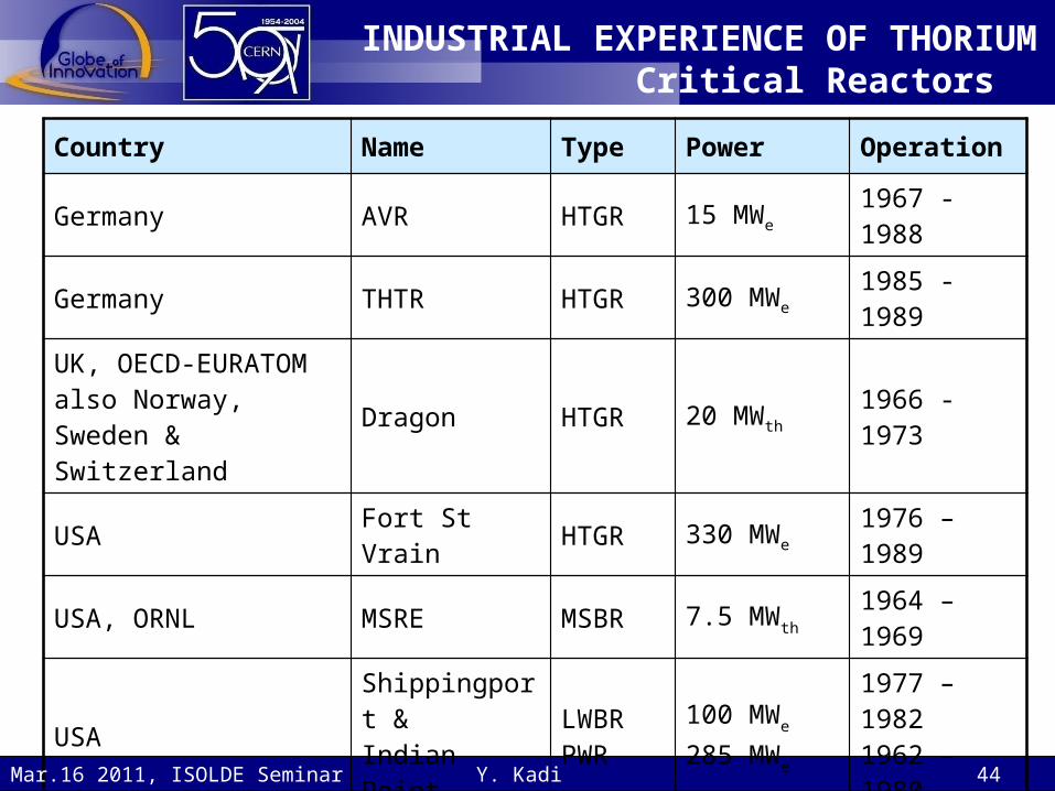
INDUSTRIAL EXPERIENCE OF THORIUMCritical Reactors
Country Name Type Power Operation
Germany AVR HTGR 15 MWe 1967 - 1988
Germany THTR HTGR 300 MWe 1985 - 1989
UK, OECD-EURATOM also Norway, Sweden & Switzerland
Dragon HTGR 20 MWth 1966 -1973
USA Fort St Vrain HTGR 330 MWe 1976 – 1989
USA, ORNL MSRE MSBR 7.5 MWth 1964 – 1969
USAShippingport &
Indian Point
LWBR PWR
100 MWe
285 MWe
1977 – 19821962 – 1980
IndiaKAMINI,CIRUS &DHRUVA
MTR
30 kWth
40 MWth
100 MWth In operation
Y. Kadi 44Mar.16 2011, ISOLDE Seminar

MOST PROJECTS USING THORIUM WERE TERMINATED BY THE 1980s
Main Reasons:The thorium fuel cycle could not compete
economically with the well-known uranium cycle
Lack of political support for the development of nuclear technology after the Chernobyl accident
Increased worldwide concern regarding the proliferation risk associated with reprocessing of spent fuel
Except for India:That utilize thorium for its long term energy
security Y. Kadi 45Mar.16 2011, ISOLDE Seminar

THORIUM AS SUSTAINABLE NUCLEAR ENERGY SOURCE FOR THE FUTURE
Y. Kadi 46Mar.16 2011, ISOLDE Seminar

THORIUM BASED FUELS ARE ATTRACTIVE FOR BOTH THERMAL &
FAST REACTORS
Y. Kadi 47Mar.16 2011, ISOLDE Seminar

ATTRIBUTES OF THORIUM
Y. Kadi 48Mar.16 2011, ISOLDE Seminar

ATTRIBUTES OF THORIUM
Y. Kadi 49Mar.16 2011, ISOLDE Seminar
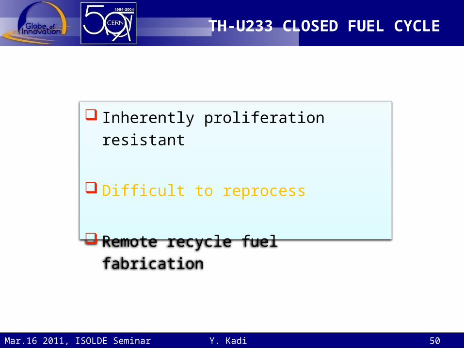
TH-U233 CLOSED FUEL CYCLE
Inherently proliferation resistant
Difficult to reprocess
Remote recycle fuel fabrication
Y. Kadi 50Mar.16 2011, ISOLDE Seminar

TH-U233 CLOSED FUEL CYCLE
Y. Kadi 51Mar.16 2011, ISOLDE Seminar