xtreme/psu-ups user manual - connect tech inc. · connect tech xtreme xtreme/psu-ups user manual...
TRANSCRIPT
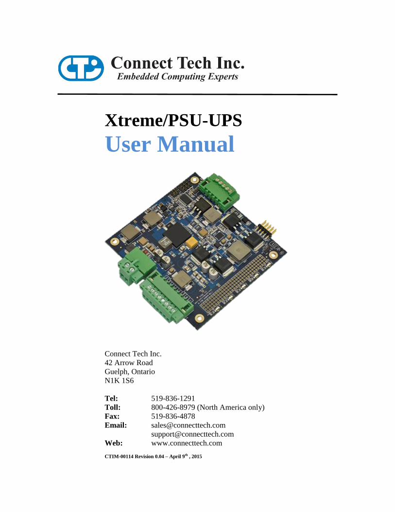
Xtreme/PSU-UPS
User Manual
Connect Tech Inc.
42 Arrow Road
Guelph, Ontario
N1K 1S6
Tel: 519-836-1291
Toll: 800-426-8979 (North America only)
Fax: 519-836-4878
Email: [email protected]
Web: www.connecttech.com
CTIM-00114 Revision 0.04 – April 9th , 2015
Connect Tech Xtreme/PSU-UPS User Manual
Revision 0.04 2
Limited Lifetime Warranty
Connect Tech Inc. provides a lifetime warranty for all of our products. Should this product, in
Connect Tech Inc.’s opinion, fail to be in good working order during the warranty period,
Connect Tech Inc. will, at its option, repair or replace this product at no charge, provided that the
product has not been subjected to abuse, misuse, accident, disaster or non Connect Tech Inc.
authorized modification or repair.
You may obtain warranty service by delivering this product to an authorized Connect Tech Inc.
business partner or directly to Connect Tech Inc. along with proof of purchase. Product returned
to Connect Tech Inc. must be pre-authorized by Connect Tech Inc. with an RMA (Return
Material Authorization) number marked on the outside of the package and sent prepaid, insured
and packaged for safe shipment. Connect Tech Inc. will return this product by prepaid ground
shipment service.
The Connect Tech Inc. lifetime warranty is defined as the serviceable life of the product. This is
defined as the period during which all components are available. Should the product prove to be
irreparable, Connect Tech Inc. reserves the right to substitute an equivalent product if available
or to retract lifetime warranty if no replacement is available.
The above warranty is the only warranty authorized by Connect Tech Inc. Under no
circumstances will Connect Tech Inc. be liable in any way for any damages, including any lost
profits, lost savings or other incidental or consequential damages arising out of the use of, or
inability to use, such product.
Copyright Notice
The information contained in this document is subject to change without notice. Connect Tech
Inc. shall not be liable for errors contained herein or for incidental consequential damages in
connection with the furnishing, performance, or use of this material. This document contains
proprietary information that is protected by copyright. All rights are reserved. No part of this
document may be photocopied, reproduced, or translated to another language without the prior
written consent of Connect Tech Inc.
Copyright 2015 by Connect Tech Inc.
Trademark Acknowledgment
Connect Tech Inc. acknowledges all trademarks, registered trademarks and/or copyrights
referred to in this document as the property of their respective owners.
Not listing all possible trademarks or copyright acknowledgments does not constitute a lack of
acknowledgment to the rightful owners of the trademarks and copyrights mentioned in this
document.
Connect Tech Xtreme Xtreme/PSU-UPS User Manual
Revision 0.04 3
Table of Contents Limited Lifetime Warranty ............................................................................................................................................... 2 Copyright Notice............................................................................................................................................................... 2 Trademark Acknowledgment ............................................................................................................................................ 2 Table of Contents .............................................................................................................................................................. 3 Revision History ............................................................................................................................................................... 3 Customer Support Overview ............................................................................................................................................. 4 Contact Information .......................................................................................................................................................... 4 Introduction....................................................................................................................................................................... 5 Detailed Technical Specifications ..................................................................................................................................... 6 Board Diagram .................................................................................................................................................................. 7 Functional Block Diagram ................................................................................................................................................ 7 Example Usage Block Diagram ........................................................................................................................................ 7 Part Number Information .................................................................................................................................................. 8 Hardware Installation ........................................................................................................................................................ 9 Input Power ......................................................................................................................................................................10
Input Power Circuit Diagram .............................................................................................................. 10 Technical Specifications...................................................................................................................... 10 Input Power Connector Pinout ............................................................................................................ 10
Output Power ...................................................................................................................................................................11 Technical Specifications...................................................................................................................... 11 Output Power Connector Pinout .......................................................................................................... 11
Battery Connector ............................................................................................................................................................12 Battery Connector Pinout .................................................................................................................... 12
Battery Support ................................................................................................................................................................12 To find a custom or off the shelf battery to meet your exact specifications please email [email protected] and we
can find the best solution to fit your needs. Configuration Jumpers ................................................................................12 J1-J4: Data configuration registers ...................................................................................................... 13 J7: SMBus Pullup Enable Jumper ........................................................................................................ 13 J8-J9: Charge configuration registers .................................................................................................. 13 PCI-104 Connector Pinout .................................................................................................................. 15
Remote ON/OFF Functionality ........................................................................................................................................16 Turn Supply ON ................................................................................................................................. 16 Turn Supply OFF ............................................................................................................................... 17
Software Interface ............................................................................................................................................................18 RS-232 .............................................................................................................................................. 18 SMBus Interface ................................................................................................................................. 18 USB .................................................................................................................................................. 19
Windows 8 / Windows 7 / Windows XP ............................................................................................19 Linux ................................................................................................................................................20
Power Sequencing Details ...............................................................................................................................................21 Detailed Specifications and Derating Graphs ..................................................................................................................23
Revision History Revision Date Author(s) Change(s)
0.00 2013-05-01 RC Initial Manual Revision Created
0.01 2013-06-13 RC Added Thermal, Power Sequencing Data.
0.02 2013-07-25 RC Added USB software information.
0.03 2015-04-02 RC Modified Jumper Table
0.04 2015-04-09 RC Added jumper info
Connect Tech Xtreme/PSU-UPS User Manual
Revision 0.04 4
Customer Support Overview
If you experience difficulties after reading the manual and/or using the product, contact the
Connect Tech Inc. reseller from which you purchased the product. In most cases the reseller can
help you with product installation and difficulties.
In the event that the reseller is unable to resolve your problem, our highly qualified support staff
can assist you. Our support section is available 24 hours a day, 7 days a week on our website at:
www.connecttech.com/sub/support/support.asp. See the contact information section below for
more information on how to contact us directly. Our technical support is always free.
Contact Information
We offer three ways for you to contact us:
Mail/Courier You may contact us by letter at: Connect Tech Inc.
Technical Support
42 Arrow Road, Guelph, ON
Canada N1K 1S6
Email/Internet
You may contact us through the Internet. Our email and URL addresses on the Internet are:
www.connecttech.com
Note:
Please go to the Download Zone or the Knowledge Database in the Support Center on the
Connect Tech Inc. website for product manuals, installation guides, device driver software and
technical tips. Submit your technical support questions to our customer support engineers via
the Support Center on the Connect Tech Inc. website.
Telephone/Facsimile Technical Support representatives are ready to answer your call Monday through Friday, from
8:30 a.m. to 5:00 p.m. Eastern Standard Time. Our numbers for calls are: Telephone: 800-426-8979 (North America only)
Telephone: 519-836-1291 (Live assistance available 8:30 a.m. to 5:00 p.m. EST, Monday to
Friday)
Facsimile: 519-836-4878 (online 24 hours)
Connect Tech Xtreme Xtreme/PSU-UPS User Manual
Revision 0.04 5
Introduction
Connect Tech’s Xtreme/PSU-UPS is a high efficiency, high powered PC/104 form factor power supply with extended
temperature capabilities. Xtreme/PSU-UPS is a highly reliable power supply which provides 154W of total output
power with +5V, +3.3V, +12V, -12V and +5V-Standby output voltages. It can be used as a stand-alone power supply
to power any other embedded system, or used directly to power any PCI-104 stack or single board computer (SBC).
The Xtreme/PSU-UPS has a wide input voltage range that accepts +9V to +36V DC and is specifically designed for use
in a broad range of rugged applications including military, industrial, and air and ground vehicles. Xtreme/PSU-UPS
can be used in combination with Connect Tech’s stackable CPU and expansion boards for a total design solution.
In addition to the power supply capabilities, the Xtreme/PSU-UPS also has the ability to charge, monitor and switch
from main supply to a backup SMART battery, providing transparent backup power to all voltage outputs. The
Xtreme/PSU-UPS is a Level 2 SMART battery charger and works with all SMART batteries, supporting charge
voltages up to +16V and charging current up to 4A.
ESD Warning Electronic components and circuits are sensitive to
ElectroStatic Discharge (ESD). When handling any circuit
board assemblies including Connect Tech COM Express
carrier assemblies, it is recommended that ESD safety
precautions be observed. ESD safe best practices include,
but are not limited to:
Leaving circuit boards in their antistatic packaging
until they are ready to be installed.
Using a grounded wrist strap when handling circuit
boards, at a minimum you should touch a grounded
metal object to dissipate any static charge that may
be present on you.
Only handling circuit boards in ESD safe areas,
which may include ESD floor and table mats, wrist
strap stations and ESD safe lab coats.
Avoiding handling circuit boards in carpeted areas.
Try to handle the board by the edges, avoiding
contact with components.
Connect Tech Xtreme/PSU-UPS User Manual
Revision 0.04 6
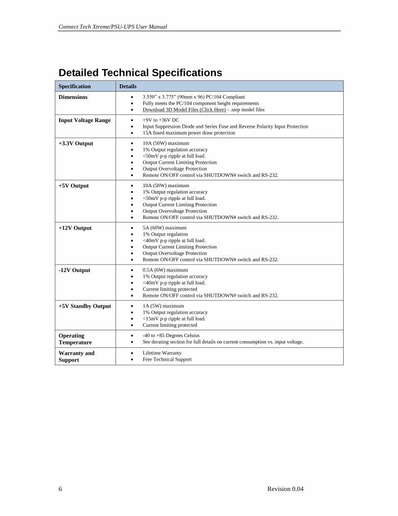
Detailed Technical Specifications Specification Details
Dimensions 3.550” x 3.775” (90mm x 96) PC/104 Compliant
Fully meets the PC/104 component height requirements
Download 3D Model Files (Click Here) - .step model files
Input Voltage Range +9V to +36V DC
Input Suppression Diode and Series Fuse and Reverse Polarity Input Protection
15A fused maximum power draw protection
+3.3V Output 10A (50W) maximum
1% Output regulation accuracy
<50mV p-p ripple at full load.
Output Current Limiting Protection
Output Overvoltage Protection
Remote ON/OFF control via SHUTDOWN# switch and RS-232.
+5V Output 10A (50W) maximum
1% Output regulation accuracy
<50mV p-p ripple at full load.
Output Current Limiting Protection
Output Overvoltage Protection
Remote ON/OFF control via SHUTDOWN# switch and RS-232.
+12V Output 5A (60W) maximum
1% Output regulation
<40mV p-p ripple at full load.
Output Current Limiting Protection
Output Overvoltage Protection
Remote ON/OFF control via SHUTDOWN# switch and RS-232.
-12V Output 0.5A (6W) maximum
1% Output regulation accuracy
<40mV p-p ripple at full load.
Current limiting protected
Remote ON/OFF control via SHUTDOWN# switch and RS-232.
+5V Standby Output 1A (5W) maximum
1% Output regulation accuracy
<15mV p-p ripple at full load.
Current limiting protected
Operating
Temperature
-40 to +85 Degrees Celsius
See derating section for full details on current consumption vs. input voltage.
Warranty and
Support
Lifetime Warranty
Free Technical Support
Connect Tech Xtreme Xtreme/PSU-UPS User Manual
Revision 0.04 7
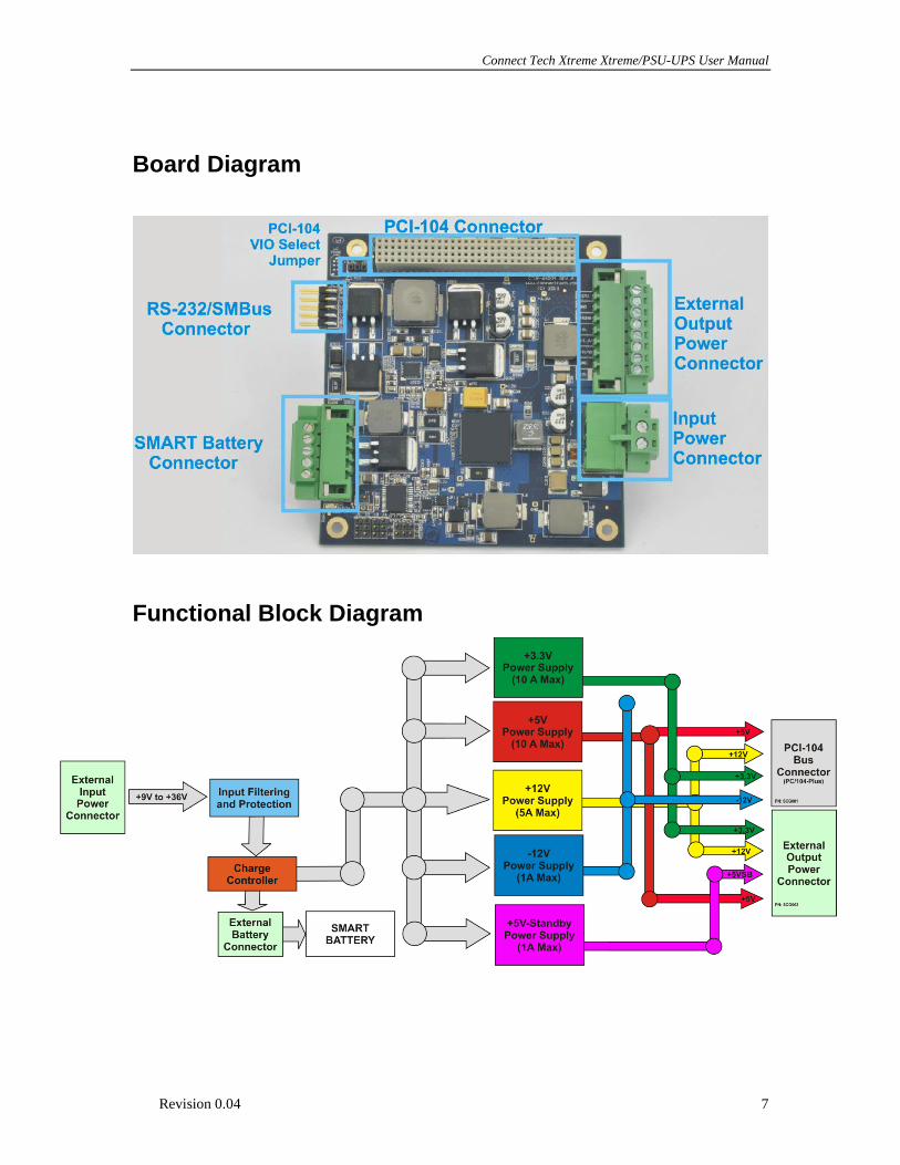
Board Diagram
Functional Block Diagram
Connect Tech Xtreme/PSU-UPS User Manual
Revision 0.04 8
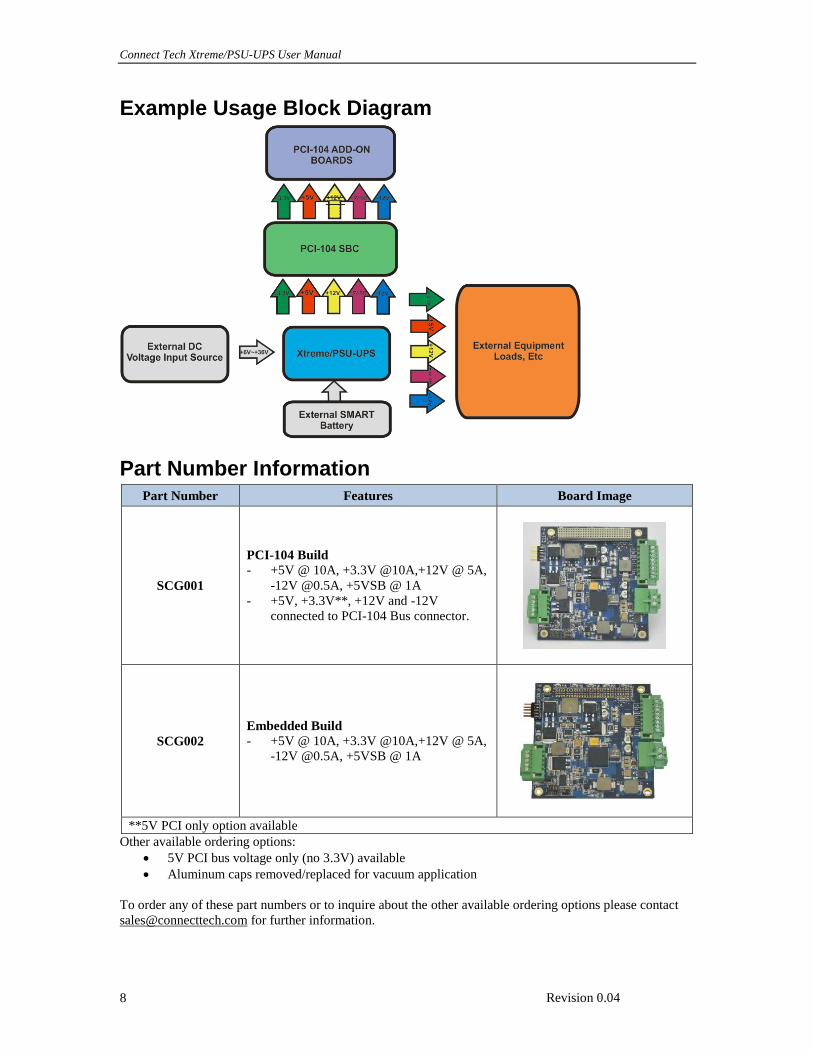
Example Usage Block Diagram
Part Number Information Part Number Features Board Image
SCG001
PCI-104 Build
- +5V @ 10A, +3.3V @10A,+12V @ 5A,
-12V @0.5A, +5VSB @ 1A
- +5V, +3.3V**, +12V and -12V
connected to PCI-104 Bus connector.
SCG002
Embedded Build
- +5V @ 10A, +3.3V @10A,+12V @ 5A,
-12V @0.5A, +5VSB @ 1A
**5V PCI only option available
Other available ordering options:
5V PCI bus voltage only (no 3.3V) available
Aluminum caps removed/replaced for vacuum application
To order any of these part numbers or to inquire about the other available ordering options please contact
[email protected] for further information.
Connect Tech Xtreme Xtreme/PSU-UPS User Manual
Revision 0.04 9
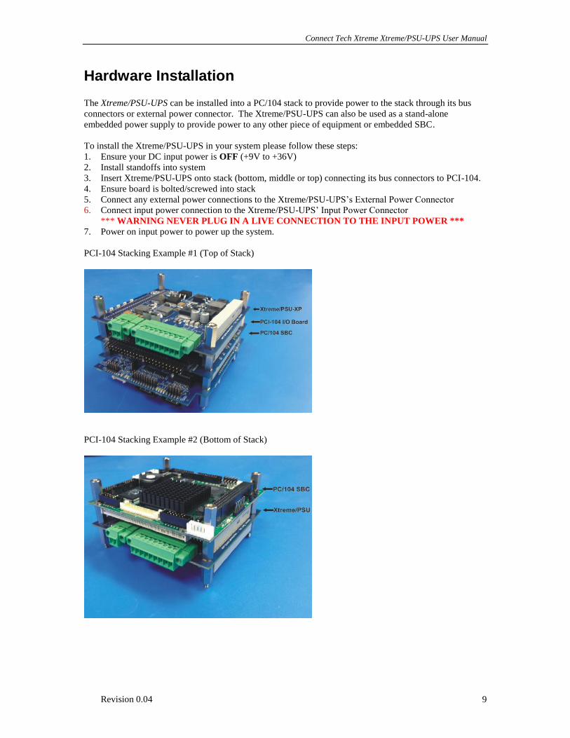
Hardware Installation
The Xtreme/PSU-UPS can be installed into a PC/104 stack to provide power to the stack through its bus
connectors or external power connector. The Xtreme/PSU-UPS can also be used as a stand-alone
embedded power supply to provide power to any other piece of equipment or embedded SBC.
To install the Xtreme/PSU-UPS in your system please follow these steps:
1. Ensure your DC input power is OFF (+9V to +36V)
2. Install standoffs into system
3. Insert Xtreme/PSU-UPS onto stack (bottom, middle or top) connecting its bus connectors to PCI-104.
4. Ensure board is bolted/screwed into stack
5. Connect any external power connections to the Xtreme/PSU-UPS’s External Power Connector
6. Connect input power connection to the Xtreme/PSU-UPS’ Input Power Connector
*** WARNING NEVER PLUG IN A LIVE CONNECTION TO THE INPUT POWER ***
7. Power on input power to power up the system.
PCI-104 Stacking Example #1 (Top of Stack)
PCI-104 Stacking Example #2 (Bottom of Stack)
Connect Tech Xtreme/PSU-UPS User Manual
Revision 0.04 10
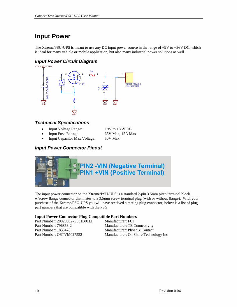
Input Power
The Xtreme/PSU-UPS is meant to use any DC input power source in the range of +9V to +36V DC, which
is ideal for many vehicle or mobile application, but also many industrial power solutions as well.
Input Power Circuit Diagram
Technical Specifications
Input Voltage Range: +9V to +36V DC
Input Fuse Rating: 65V Max, 15A Max
Input Capacitor Max Voltage: 50V Max
Input Power Connector Pinout
The input power connector on the Xtreme/PSU-UPS is a standard 2-pin 3.5mm pitch terminal block
w/screw flange connector that mates to a 3.5mm screw terminal plug (with or without flange). With your
purchase of the Xtreme/PSU-UPS you will have received a mating plug connector, below is a list of plug
part numbers that are compatible with the PSG.
Input Power Connector Plug Compatible Part Numbers
Part Number: 20020002-G031B01LF Manufacturer: FCI
Part Number: 796858-2 Manufacturer: TE Connectivity
Part Number: 1835478 Manufacturer: Phoenix Contact
Part Number: OSTVM027552 Manufacturer: On Shore Technology Inc
Connect Tech Xtreme Xtreme/PSU-UPS User Manual
Revision 0.04 11
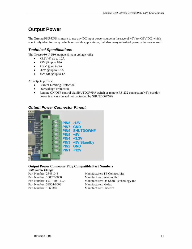
Output Power
The Xtreme/PSU-UPS is meant to use any DC input power source in the rage of +9V to +36V DC, which
is not only ideal for many vehicle or mobile applications, but also many industrial power solutions as well.
Technical Specifications
The Xtreme/PSU-UPS outputs 5 main voltage rails:
+3.3V @ up to 10A
+5V @ up to 10A
+12V @ up to 5A
-12V @ up to 0.5A
+5V-SB @ up to 1A
All outputs provide:
Current Limiting Protection
Overvoltage Protection
Remote ON/OFF control via SHUTDOWN# switch or remote RS-232 connection(+5V standby
power is always on and not controlled by SHUTDOWN#)
Output Power Connector Pinout
Output Power Connector Plug Compatible Part Numbers With Screw Flange
Part Number: 284510-8 Manufacturer: TE Connectivity
Part Number: 1606700000 Manufacturer: Weidmuller
Part Number: OSTTJ0811520 Manufacturer: On Shore Technology Inc
Part Number: 39504-0008 Manufacturer: Molex
Part Number: 1863369 Manufacturer: Phoenix
Connect Tech Xtreme/PSU-UPS User Manual
Revision 0.04 12
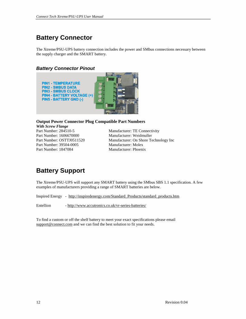
Battery Connector
The Xtreme/PSU-UPS battery connection includes the power and SMbus connections necessary between
the supply charger and the SMART battery.
Battery Connector Pinout
Output Power Connector Plug Compatible Part Numbers With Screw Flange
Part Number: 284510-5 Manufacturer: TE Connectivity
Part Number: 1606670000 Manufacturer: Weidmuller
Part Number: OSTTJ0511520 Manufacturer: On Shore Technology Inc
Part Number: 39504-0005 Manufacturer: Molex
Part Number: 1847084 Manufacturer: Phoenix
Battery Support
The Xtreme/PSU-UPS will support any SMART battery using the SMbus SBS 1.1 specification. A few
examples of manufacturers providing a range of SMART batteries are below.
Inspired Energy - http://inspiredenergy.com/Standard_Products/standard_products.htm
Entellion - http://www.accutronics.co.uk/vr-series-batteries/
To find a custom or off the shelf battery to meet your exact specifications please email
[email protected] and we can find the best solution to fit your needs.
Connect Tech Xtreme Xtreme/PSU-UPS User Manual
Revision 0.04 13
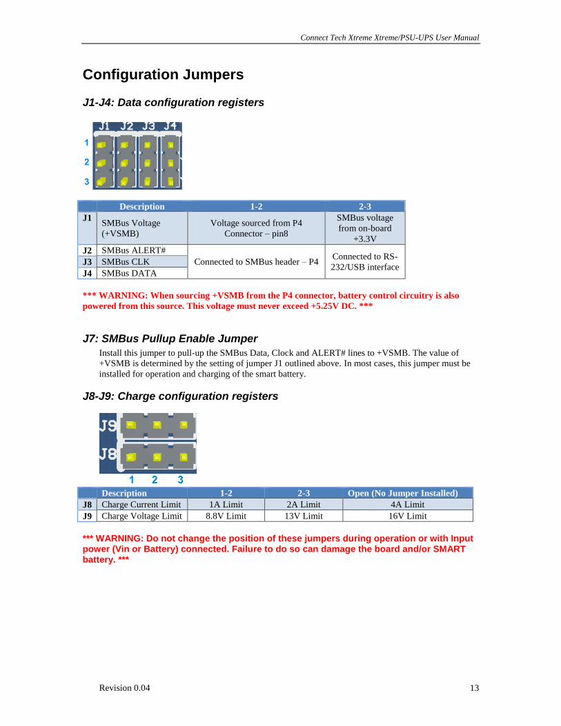
Configuration Jumpers
J1-J4: Data configuration registers
Description 1-2 2-3
J1 SMBus Voltage
(+VSMB)
Voltage sourced from P4
Connector – pin8
SMBus voltage
from on-board
+3.3V
J2 SMBus ALERT#
Connected to SMBus header – P4 Connected to RS-
232/USB interface J3 SMBus CLK
J4 SMBus DATA
*** WARNING: When sourcing +VSMB from the P4 connector, battery control circuitry is also
powered from this source. This voltage must never exceed +5.25V DC. ***
J7: SMBus Pullup Enable Jumper
Install this jumper to pull-up the SMBus Data, Clock and ALERT# lines to +VSMB. The value of
+VSMB is determined by the setting of jumper J1 outlined above. In most cases, this jumper must be
installed for operation and charging of the smart battery.
J8-J9: Charge configuration registers
Description 1-2 2-3 Open (No Jumper Installed)
J8 Charge Current Limit 1A Limit 2A Limit 4A Limit
J9 Charge Voltage Limit 8.8V Limit 13V Limit 16V Limit
*** WARNING: Do not change the position of these jumpers during operation or with Input power (Vin or Battery) connected. Failure to do so can damage the board and/or SMART battery. ***
Connect Tech Xtreme/PSU-UPS User Manual
Revision 0.04 14
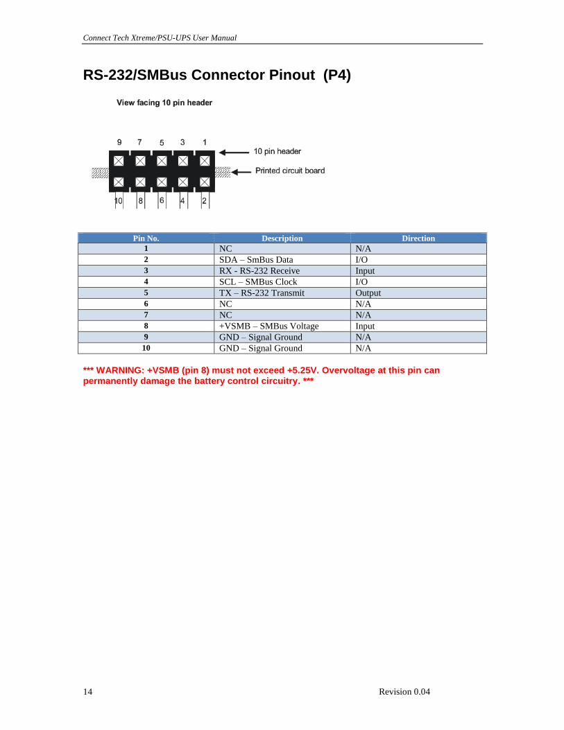
RS-232/SMBus Connector Pinout (P4)
Pin No. Description Direction
1 NC N/A
2 SDA – SmBus Data I/O
3 RX - RS-232 Receive Input
4 SCL – SMBus Clock I/O
5 TX – RS-232 Transmit Output
6 NC N/A
7 NC N/A
8 +VSMB – SMBus Voltage Input
9 GND – Signal Ground N/A
10 GND – Signal Ground N/A
*** WARNING: +VSMB (pin 8) must not exceed +5.25V. Overvoltage at this pin can permanently damage the battery control circuitry. ***
Connect Tech Xtreme Xtreme/PSU-UPS User Manual
Revision 0.04 15
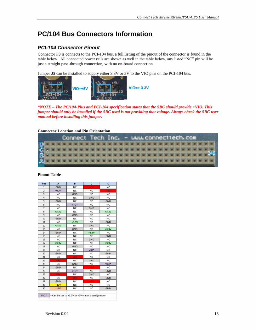
PC/104 Bus Connectors Information PCI-104 Connector Pinout
Connector P3 is connects to the PCI-104 bus, a full listing of the pinout of the connector is found in the
table below. All connected power rails are shown as well in the table below, any listed “NC” pin will be
just a straight pass-through connection, with no on-board connection.
Jumper J5 can be installed to supply either 3.3V or 5V to the VIO pins on the PCI-104 bus.
*NOTE – The PC/104-Plus and PCI-104 specification states that the SBC should provide +VIO. This
jumper should only be installed if the SBC used is not providing that voltage. Always check the SBC user
manual before installing this jumper.
Connector Location and Pin Orientation
Pinout Table
Pin A B C D
1 GND NC +5V NC
2 VIO* NC NC +5V
3 NC GND NC NC
4 NC NC GND NC
5 GND NC NC GND
6 NC VIO* NC NC
7 NC NC GND NC
8 +3.3V NC NC +3.3V
9 NC GND NC NC
10 GND NC NC NC
11 NC +3.3V NC GND
12 +3.3V NC GND NC
13 NC GND NC +3.3V
14 GND NC +3.3V NC
15 NC NC NC GND
16 NC NC GND NC
17 +3.3V NC NC +3.3V
18 NC GND NC NC
19 NC NC VIO* NC
20 GND NC NC GND
21 NC +5V NC NC
22 +5V NC GND NC
23 NC GND NC VIO*
24 GND NC +5V NC
25 NC VIO* NC GND
26 +5V NC GND NC
27 NC +5V NC GND
28 GND NC +5V NC
29 +12V NC NC NC
30 -12V NC NC GND
VIO* = Can be set to +3.3V or +5V via on board jumper
Connect Tech Xtreme/PSU-UPS User Manual
Revision 0.04 16
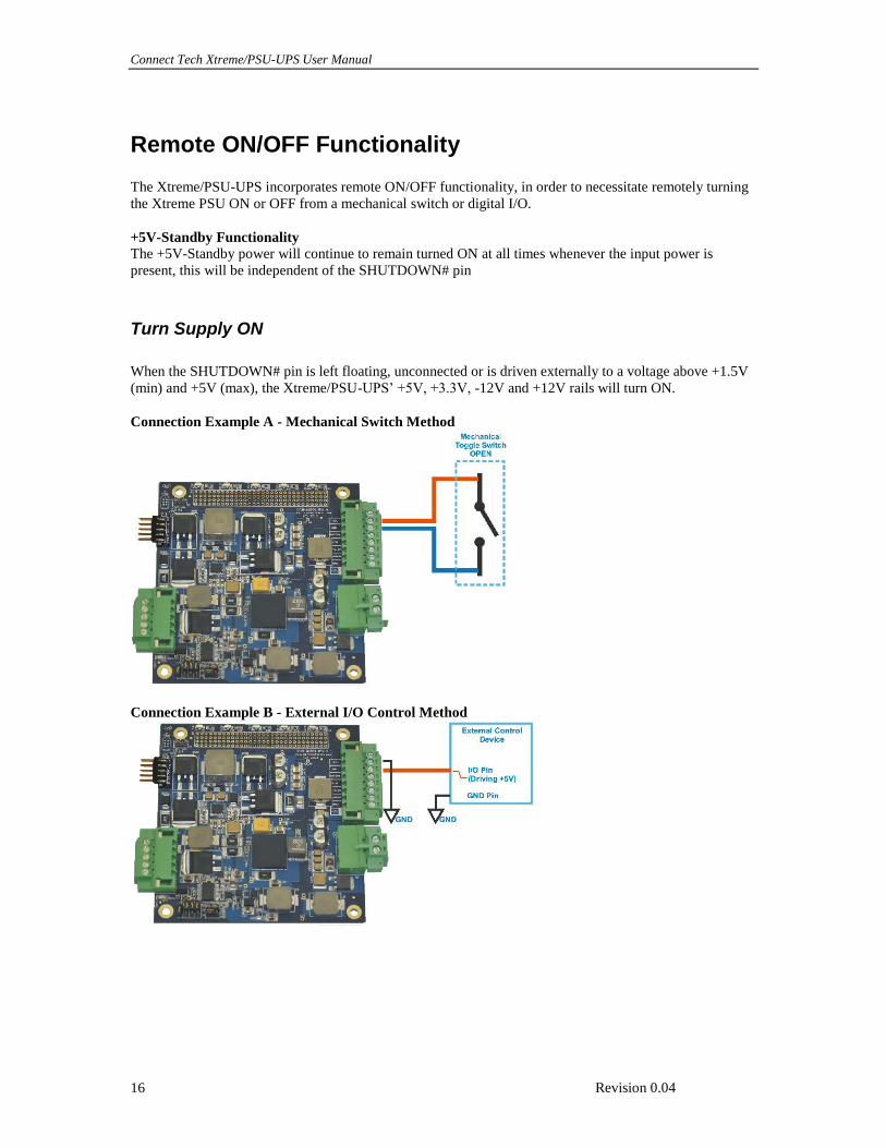
Remote ON/OFF Functionality
The Xtreme/PSU-UPS incorporates remote ON/OFF functionality, in order to necessitate remotely turning
the Xtreme PSU ON or OFF from a mechanical switch or digital I/O.
+5V-Standby Functionality
The +5V-Standby power will continue to remain turned ON at all times whenever the input power is
present, this will be independent of the SHUTDOWN# pin
Turn Supply ON
When the SHUTDOWN# pin is left floating, unconnected or is driven externally to a voltage above +1.5V
(min) and +5V (max), the Xtreme/PSU-UPS’ +5V, +3.3V, -12V and +12V rails will turn ON.
Connection Example A - Mechanical Switch Method
Connection Example B - External I/O Control Method
Connect Tech Xtreme Xtreme/PSU-UPS User Manual
Revision 0.04 17
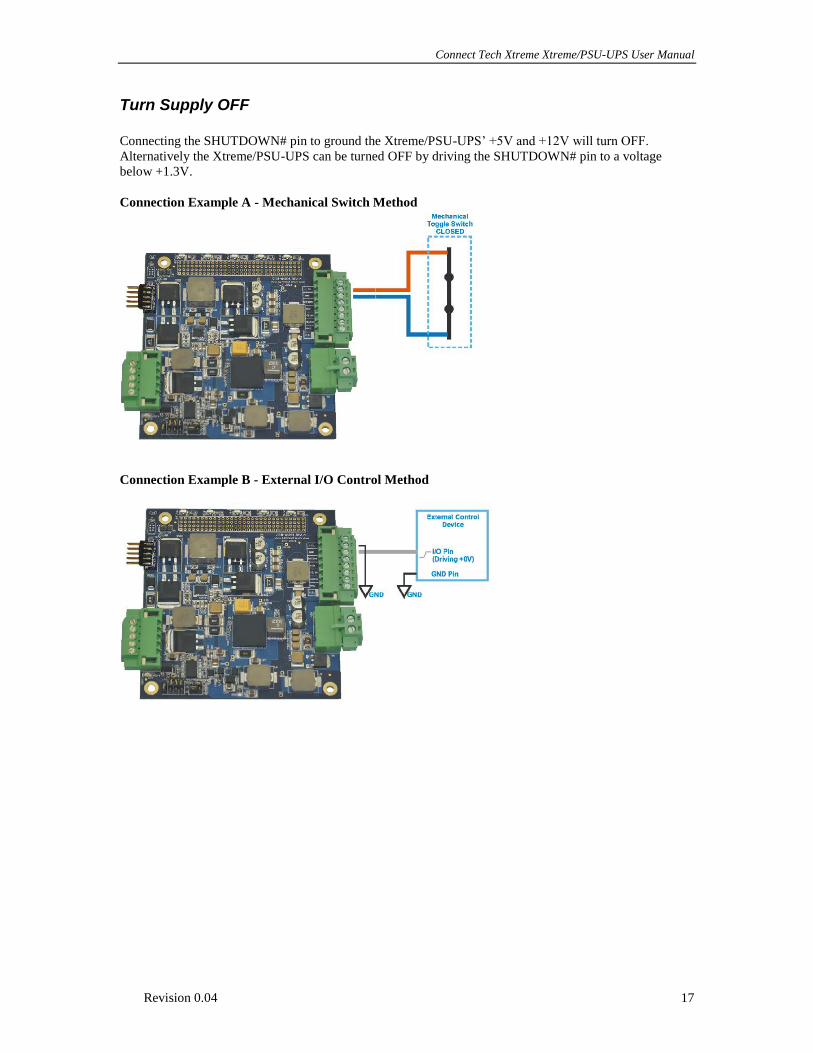
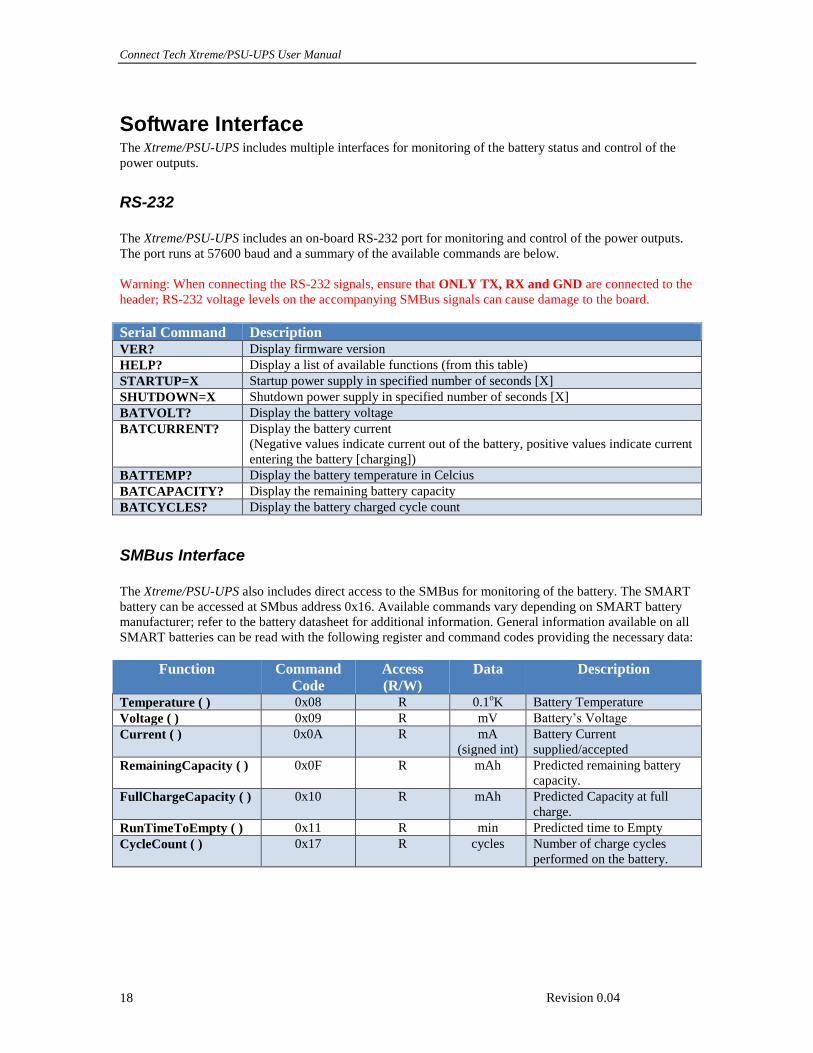
Turn Supply OFF
Connecting the SHUTDOWN# pin to ground the Xtreme/PSU-UPS’ +5V and +12V will turn OFF.
Alternatively the Xtreme/PSU-UPS can be turned OFF by driving the SHUTDOWN# pin to a voltage
below +1.3V.
Connection Example A - Mechanical Switch Method
Connection Example B - External I/O Control Method
Connect Tech Xtreme/PSU-UPS User Manual
Revision 0.04 18
Software Interface The Xtreme/PSU-UPS includes multiple interfaces for monitoring of the battery status and control of the
power outputs.
RS-232
The Xtreme/PSU-UPS includes an on-board RS-232 port for monitoring and control of the power outputs.
The port runs at 57600 baud and a summary of the available commands are below.
Warning: When connecting the RS-232 signals, ensure that ONLY TX, RX and GND are connected to the
header; RS-232 voltage levels on the accompanying SMBus signals can cause damage to the board.
Serial Command Description VER? Display firmware version
HELP? Display a list of available functions (from this table)
STARTUP=X Startup power supply in specified number of seconds [X]
SHUTDOWN=X Shutdown power supply in specified number of seconds [X]
BATVOLT? Display the battery voltage
BATCURRENT? Display the battery current
(Negative values indicate current out of the battery, positive values indicate current
entering the battery [charging])
BATTEMP? Display the battery temperature in Celcius
BATCAPACITY? Display the remaining battery capacity
BATCYCLES? Display the battery charged cycle count
SMBus Interface
The Xtreme/PSU-UPS also includes direct access to the SMBus for monitoring of the battery. The SMART
battery can be accessed at SMbus address 0x16. Available commands vary depending on SMART battery
manufacturer; refer to the battery datasheet for additional information. General information available on all
SMART batteries can be read with the following register and command codes providing the necessary data:
Function Command
Code
Access
(R/W)
Data Description
Temperature ( ) 0x08 R 0.1oK Battery Temperature
Voltage ( ) 0x09 R mV Battery’s Voltage
Current ( ) 0x0A R mA
(signed int)
Battery Current
supplied/accepted
RemainingCapacity ( ) 0x0F R mAh Predicted remaining battery
capacity.
FullChargeCapacity ( ) 0x10 R mAh Predicted Capacity at full
charge.
RunTimeToEmpty ( ) 0x11 R min Predicted time to Empty
CycleCount ( ) 0x17 R cycles Number of charge cycles
performed on the battery.
Connect Tech Xtreme Xtreme/PSU-UPS User Manual
Revision 0.04 19
USB
The Xtreme/PSU-UPS includes an on-board micro USB port for monitoring of battery state, power status
and other critical power management information. The interface adheres to the USB-HID Battery standard
and is supported natively in Windows and using the Network UPS Driver (NUT) in Linux distributions.
Windows 8 / Windows 7 / Windows XP
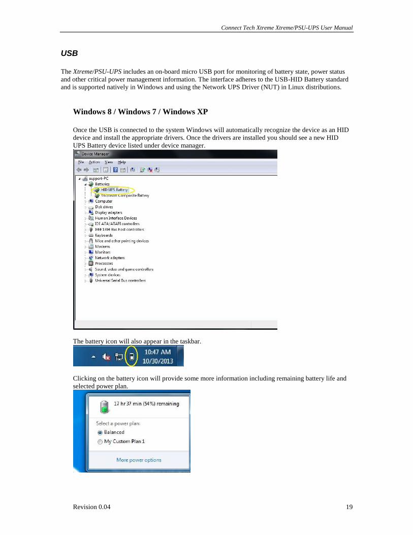
Once the USB is connected to the system Windows will automatically recognize the device as an HID
device and install the appropriate drivers. Once the drivers are installed you should see a new HID
UPS Battery device listed under device manager.
The battery icon will also appear in the taskbar.
Clicking on the battery icon will provide some more information including remaining battery life and
selected power plan.
Connect Tech Xtreme/PSU-UPS User Manual
Revision 0.04 20
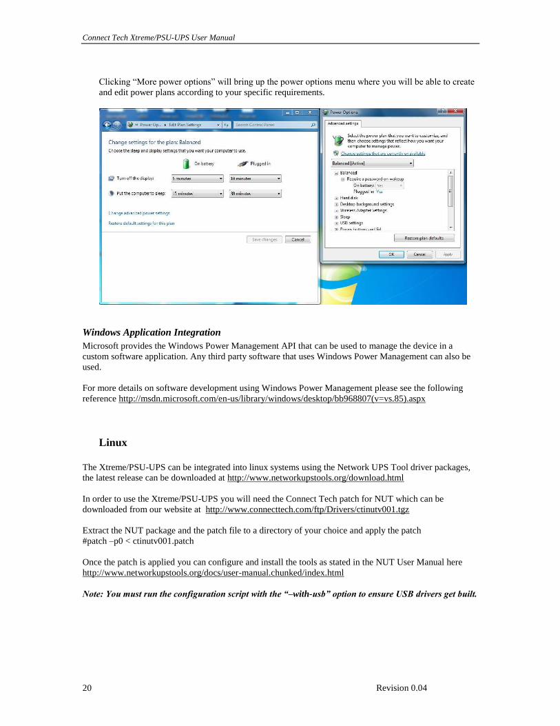
Clicking “More power options” will bring up the power options menu where you will be able to create
and edit power plans according to your specific requirements.
Windows Application Integration
Microsoft provides the Windows Power Management API that can be used to manage the device in a
custom software application. Any third party software that uses Windows Power Management can also be
used.
For more details on software development using Windows Power Management please see the following
reference http://msdn.microsoft.com/en-us/library/windows/desktop/bb968807(v=vs.85).aspx
Linux
The Xtreme/PSU-UPS can be integrated into linux systems using the Network UPS Tool driver packages,
the latest release can be downloaded at http://www.networkupstools.org/download.html
In order to use the Xtreme/PSU-UPS you will need the Connect Tech patch for NUT which can be
downloaded from our website at http://www.connecttech.com/ftp/Drivers/ctinutv001.tgz
Extract the NUT package and the patch file to a directory of your choice and apply the patch
#patch –p0 < ctinutv001.patch
Once the patch is applied you can configure and install the tools as stated in the NUT User Manual here
http://www.networkupstools.org/docs/user-manual.chunked/index.html
Note: You must run the configuration script with the “–with-usb” option to ensure USB drivers get built.
Connect Tech Xtreme Xtreme/PSU-UPS User Manual
Revision 0.04 21
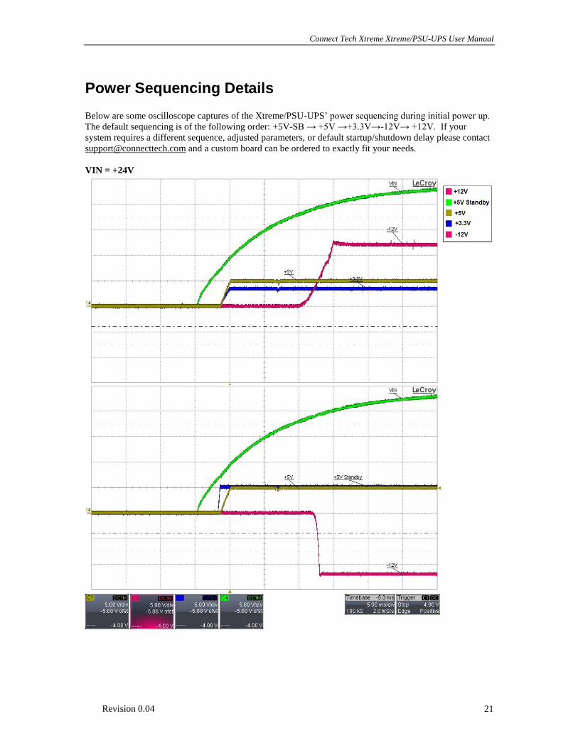
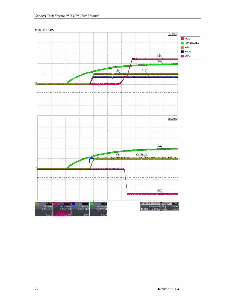
Power Sequencing Details
Below are some oscilloscope captures of the Xtreme/PSU-UPS’ power sequencing during initial power up.
The default sequencing is of the following order: +5V-SB → +5V →+3.3V→-12V→ +12V. If your
system requires a different sequence, adjusted parameters, or default startup/shutdown delay please contact
[email protected] and a custom board can be ordered to exactly fit your needs.
VIN = +24V
Connect Tech Xtreme/PSU-UPS User Manual
Revision 0.04 22
VIN = +10V
Connect Tech Xtreme Xtreme/PSU-UPS User Manual
Revision 0.04 23
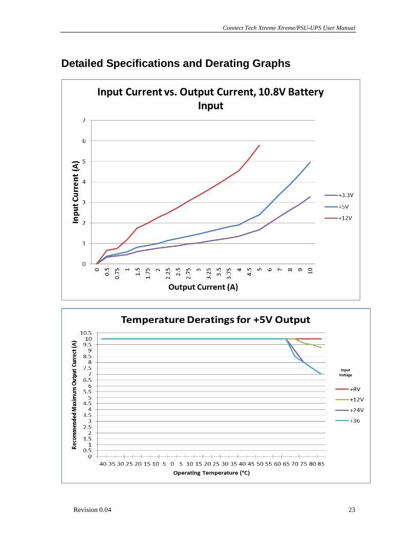
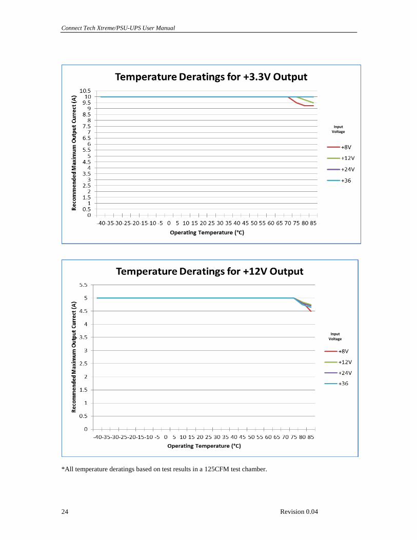
Detailed Specifications and Derating Graphs
Input Voltage
Connect Tech Xtreme/PSU-UPS User Manual
Revision 0.04 24
*All temperature deratings based on test results in a 125CFM test chamber.
Input Voltage
Input Voltage