wsrc-im-91-116-0 · wsrc-im-91-116-0 revision page page 1 of 10 date: 9/18 revision 12 dwpf waste...
TRANSCRIPT


WSRC-IM-91-116-0
Revision Page
Page 1 of 10
Date: 9/18
Revision 12
DWPF WASTE FORM COMPLIANCE PLAN
REVISION PAGE
The following is a summary of the major changes made to the Waste Form
Compliance Plan.
Revision 12, September 2018
Part Item Revisions
2
100
Updated discussion and Figure 2.100.1 to be inclusive of
glycolic acid flowsheet.
3
3
3
3
5
App
200
400
500
800
850
1.200.1
Updated the listed WCP sections (including figures) to
reflect that, beginning with Sludge Batch 9, DWPF glass
pour stream samples will be collected and archived at SRNL
but no longer routinely analyzed for inclusion in the
Production Records.
Additionally, in WCP Section 3/Part 400 and Appendix
1.200.1, clarified that for macrobatches analyzed after
2015, the initial index year for radionuclide reporting
will be the year of radionuclide analysis and not 2015.
Added new reference SRR-WSE-218-00020.
Also, in WCP Section 3/Part 500, updated discussion to
remove glass fabrication and performance of the PCT on the
sludge batch qualification sample.
5 400 Corrected smear pad surface area and updated Figure
5.400.1.

WSRC-IM-91-116-0
Revision Page
Page 2 of 10
Date: 9/18
Revision 12
Revision 11, June 2016 (Incorporated X-DCF-S-00199 and M-DCF-S-02907)
Part Item Revisions
2
100
Added discussion related to double stacking canisters in
GWSB#1. Also, clarified discussion that natural
convection is relied upon in both GWSBs for canister
cooling. Updated Figures 2.100.1 and 2.100.2.
3
600
Added discussion related to double stacking canisters in
GWSB#1 in relation to the 400°C temperature limit. Also,
clarified discussion that natural convection is relied
upon in both GWSBs for canister cooling per X-DCF-S-00199.
Added ASTM E1356 standard.
4 100 Incorporated M-DCF-S-02907 (Canister Nozzle Forging ASTM
Standard).
5
650
Added discussion related to double stacking canisters and
its non-impact on the subcriticality specification.
Revision 10, March 2014
Part Item Revisions
4
4
100
400
Clarified that canisters with material specifications out
of range will be identified as nonconforming vs. not
acceptable for use.
Clarified that canisters with dimensions out of range will
be identified as nonconforming vs. not acceptable for use.
Revision 9, June 2012
Part Item Revisions
3
200
Removed specificity of sampling feed material with
Hydragard valve.

WSRC-IM-91-116-0
Revision Page
Page 3 of 10
Date: 9/18
Revision 12
Revision 8, March 2006 (Incorporated X-DCF-S-00191 and X-DCF-S-00193)
Part Item Revisions
1
2
3
3
3
3
3
3
5
5
5
300
100
100
200
300
400
500
600
450
550
650
General: In each Item and Part listed, references to
precipitate batches and PHA were replaced with salt
effluent batches, where applicable.
General: Updated references to canister storage facilities
to include multiple Glass Waste Storage Buildings. Also
incorporated X-DCF-S-00191 and X-DCF-S-00193.
App 1.200.1
App 1.200.2
App 1.200.3

WSRC-IM-91-116-0
Revision Page
Page 4 of 10
Date: 9/18
Revision 12
Revision 7, May 2003
Part Item Revisions
1
3
3
3
3
4
5
300
200
400
500
800
200
850
Removed reference to sampling MFT for reporting purposes.
Removed references to MFT sampling and clarified frequency
of pour stream sampling.
Removed discussion concerning direct measurement of
radionuclides at DWPF for reporting purposes and clarified
frequency of pour stream sampling.
Clarified frequency of pour stream sampling.
Removed discussion concerning direct measurement of
radionuclides at DWPF for reporting purposes and clarified
frequency of pour stream sampling.
Removed discussion of final weld inspection.
Clarified frequency of pour stream sampling.
App 1.200.1 Clarified frequency of pour stream sampling.

WSRC-IM-91-116-0
Revision Page
Page 5 of 10
Date: 9/18
Revision 12
Revision 6, September 1999 (Incorporated M-DCF-S-01535)
Part Item Revisions
1
1
1
2
3
3
3
3
3
3
3
3
4
100
200
300
100
100
200
300
400
500
600
700
800
100
Revised organization titles and references.
Deleted FA-20 write-up.
Deleted “QAPD” acronym and “DWPF Batches” figure. Revised
definitions to reflect current status of sludge and
precipitate processing.
Updated description to reflect state of precipitate
processing. Modified “canister filling” write-up.
Deleted reference to New Production Reactor. Added Part
2/Item 100 flag for precipitate processing status.
Revised the sampling and analytical sections to include
the lab insert and alternate analytical methods. Removed
unnecessary detail (including one table and two figures).
Deleted term “periodically” from glass sampling
discussion. Added Part 2/Item 100 flag for precipitate
processing status.
Removed reference to outdated organization. Added Part
2/Item 100 flag for precipitate processing status.
Deleted unnecessary detail (including two tables). Deleted
term “periodically” from glass sampling discussion. Added
Part 2/Item 100 flag for precipitate processing status.
Revised the GPCP section to include the use of the lab
insert method. Removed unnecessary detail (including two
figures). Deleted term “periodically” from glass sampling
discussion. Added Part 2/Item 100 flag for precipitate
processing status.
Clarified determination of “end of initial cooldown”.
Incorporated revised WAPS requirement.
Added new section to address WAPS 1.6 (new).
Corrected table numbering. Clarified information in
tables. Modified text to state that canister procurement
specification is referenced, not included, in WQR.

WSRC-IM-91-116-0
Revision Page
Page 6 of 10
Date: 9/18
Revision 12
4
4
4
5
5
5
5
5
5
5
5
5
5
5
5
6
6
6
200
300
400
100
150
250
400
450
500
550
650
700
750
800
850
100
200
300
Incorporated revised WAPS req. Revised text to reflect
reduction of testing and inspections in the DWPF canister
procurement spec as well as revised fabrication method.
Removed tolerances and weld plug dimensions from figure.
Removed tolerances in Figure 4.300.3.
Incorporated revised WAPS requirement.
Removed unnecessary detail. Corrected joint leak rate to
be consistent with canister procurement specification.
Incorporated revised WAPS requirement.
Incorporated revised WAPS requirement.
Incorporated revised WAPS requirement (relaxation of the
specification for removable contamination). Generalized
smear paper to smear pad. Removed unnecessary detail
(including one figure).
Added Part 2/Item 100 flag for prec. processing status.
Deleted discussion related to calorimetric experiments.
Incorporated revised WAPS requirement. Added Part 2/Item
100 flag for precipitate processing status.
Incorporated revised WAPS requirement. Added Part 2/Item
100 flag for precipitate processing status.
Incorporated revised WAPS requirement.
Incorporated revised WAPS requirement.
Incorporated revised WAPS requirement. Updated drawing
number for canister lifting flange. Removed tolerances
from lifting flange geometry figure. Removed unnecessary
detail (including a table and a figure).
Added new section to address WAPS 3.14 (new).
Incorporated revised WAPS requirement. Revised
organization titles and references. Deleted QAPD.
Revised references (deleted QAPD).
Revised references (deleted QAPD).

WSRC-IM-91-116-0
Revision Page
Page 7 of 10
Date: 9/18
Revision 12
App. 1.100.1
App. 1.200.1
App. 1.200.2
App. 1.200.3
Added WAPS 1.6 and 3.14 to WQR Volume 4.
Incorporated new IAEA WAPS requirements (1.6, 3.14) into
the Production Records. Updated organization titles.
Modified macro-batch definition and timing of delivery of
Production Records. Revised strategy associated with
documenting glass sample analyses.
Revised description of monitoring of temperature in GWSB.
Revised removable contamination levels. Modified timing
of delivery of Storage and Shipping Records.
Deleted FA-20 startup test footnote. Revised GWSB
temperature monitoring discussion.

WSRC-IM-91-116-0
Revision Page
Page 8 of 10
Date: 9/18
Revision 12
Revision 5, November 1995
Part Item Revisions
1
1
2
3
3
3
3
3
3
4
4
5
5
5
5
5
5
6
100
200
100
100
200
400
500
600
700
100
200
100
150
200
300
350
400
300
Updated DOE organization title.
Deleted drain valve testing in WP-15 and WP-16. Deleted
reference to surface thermocouples. Deleted ref. to weld
repair cap. Deleted WP-23. Updated WP-17 description.
Deleted reference to surface thermocouples. Deleted
reference to weld repair cap.
Changed MnO2 to MnO.
Clarified Figure 3.200.1. Updated analytical methods.
Updated analytical methods.
Updated figure of glass pour stream sampler.
Deleted reference to WP-23.
Updated specification.
Updated specification. Added text addressing secondary
canister.
Deleted discussion of measuring plug displacement and
visual observation of final weld. Deleted reference to
welding canisters for ASME qualification testing.
Updated leak rate sensitivity.
Updated specification.
Updated specification.
Updated specification.
Clarified glass level reporting. Deleted reference to
surface thermocouples. Modified target fill level to 96
inches.
Updated specification. Clarified smear test Operations.
Updated specification.

WSRC-IM-91-116-0
Revision Page
Page 9 of 10
Date: 9/18
Revision 12
App. 1.100.1
App. 1.200.1
App. 1.200.2
App. 1.200.3
Updated revision number and date.
Deleted reference to surface thermocouples.
Updated revision number and date.
Deleted reference to WP-23 and updated strategies for GWSB
evaluations. Clarified description of Waste Qualification
Runs.
Revision 4, December 1994 (Incorporated M-DCF-S-00332 and G-DCF-S-00012)
Part
Item
Revisions
1
2
3
3
5
5
5
200
100
200
500
350
400
800
Modified description of testing of glass level detection
method.
Modified description of glass level detection method.
Modified Figure 3.200.4 to reflect sampler modification.
Deleted reference to Fe2+/Fe(total) for redox
determination.
Modified compliance method for glass level detection.
Added detail to logic diagram.
Changed figure of canister grapple to reflect
modifications.
App. 1.200.1
App. 1.200.3
Modified method for reporting glass fill level.
Added detail on testing to be performed during
Qualification Runs.

WSRC-IM-91-116-0
Revision Page
Page 10 of 10
Date: 9/18
Revision 12
Revision 3, April 1994
Part Item Revisions
1
1
1
2
3
3
4
5
5
5
5
5
6
6
6
6
100
200
300
100
200
500
200
100
150
200
250
350
100
200
300
400
Clarified documentation requirements.
Clarified test plan listing. Added reference to Waste
Form Qualification Coordinating Plan.
Added more detail to glossary.
Minor changes to process description.
Added pointer to WQR Volume 2.
Clarified text describing information to be reported for
demonstration of control.
Added statement that welder will be qualified.
Clarified use of temporary cover.
Added statement that DWPF process cannot pressurize the
canistered waste form.
Grammatical correction.
Grammatical correction.
Added text on disposition of underfilled canistered waste
forms.
Clarified implementation of quality assurance requirements
and organizational responsibilities.
Added statement that WCP is basis for waste acceptance
process items and activities.
Added “action” plan.
New section.
App. 1.100.1
App. 1.200.1
App. 1.200.2
Deleted WAPS and added WQR volume listing.
Clarified information to be reported in the Production
Records.
Changed shipment date of “2008” to “2015”.

WSRC-IM-91-116-0
Table of Contents
Page 1 of 3
Date: 9/18
Revision 12
DWPF WASTE FORM COMPLIANCE PLAN
TABLE OF CONTENTS
Part Item
INTRODUCTION
Waste Acceptance Process
Overview of the Waste Form Compliance Plan
Glossary and List of Acronyms
1
1
1
1
100
200
300
DWPF PROCESS DESCRIPTION
Overview of DWPF Process
2
2
100
WASTE FORM SPECIFICATIONS
1.1 Chemical Specification
1.1.1 Chemical Composition Projections
1.1.2 Chemical Composition during Production
1.2 Radionuclide Inventory Specification
1.2.1 Radionuclide Inventory Projections
1.2.2 Radionuclide Inventory during Production
1.3 Specification for Product Consistency
1.4 Specification for Phase Stability
1.5 Hazardous Waste Specification
1.6 IAEA Safeguards Reporting for HLW Specification
3
3
3
3
3
3
3
3
3
100
200
300
400
500
600
700
800
CANISTER SPECIFICATIONS
2.1 Material Specification
2.2 Fabrication and Closure Specification
4
4
4
100
200

WSRC-IM-91-116-0
Table of Contents
Page 2 of 3
Date: 9/18
Revision 12
2.3 Identification and Labeling Specification
2.4 Specification for Canister Length and Diameter
4
4
300
400
Part
Item
CANISTERED WASTE FORM SPECIFICATIONS
3.1 Free Liquid Specification
3.2 Gas Specifications
3.3 Specification for Explosiveness, Pyrophoricity,
and Combustibility
3.4 Organic Materials Specification
3.5 Chemical Compatibility Specification
3.6 Fill Height Specification
3.7 Specification for Removable Radioactive
Contamination on External Surfaces
3.8 Heat Generation Specification
3.8.1 Heat Generation Projections
3.8.2 Heat Generation at Year of Shipment
3.9 Specification for Maximum Dose Rates
3.9.1 Projections of Dose Rates
3.9.2 Dose Rates at Time of Shipment
3.10 Subcriticality Specification
3.11 Specifications for Weight and Overall
Dimensions
3.12 Drop Test Specification
3.13 Handling Features Specification
3.14 Concentration of Plutonium in each Canister
Specification
5
5
5
5
5
5
5
5
5
5
5
5
5
5
5
5
5
100
150
200
250
300
350
400
450
500
550
600
650
700
750
800
850

WSRC-IM-91-116-0
Table of Contents
Page 3 of 3
Date: 9/18
Revision 12
QUALITY ASSURANCE
Quality Assurance Specification
Changes Relating to Waste Acceptance Process
Activities
Disposition of Nonconforming Canistered Waste Forms
6
6
6
6
100
200
300
APPENDICES
1.100.1 Contents of DWPF Waste Form Qualification Report
1.200.1 Description of the Production Records for DWPF Canistered Waste
Forms
1.200.2 Description of the Storage and Shipping Records for DWPF Canistered
Waste Forms
1.200.3 Summary of DWPF Qualification Runs Activities

WSRC-IM-91-116-0
Part 1
Item 100
Page 1 of 3
Date: 9/99
Revision 6
PART TITLE: INTRODUCTION
ITEM TITLE: WASTE ACCEPTANCE PROCESS
The Department of Energy currently has approximately 130 million liters of
high-level radioactive waste in storage at the Savannah River Site (SRS).
These wastes, which were generated during the production of nuclear materials
for defense needs, have been stored as alkaline slurries in large carbon-steel
tanks. This mode of storage, begun in the mid-1950's, has proven to be a safe
and effective way of isolating the hazardous radionuclides from the
environment.
However, while storage of liquid waste has been safe and effective, it has
required continuous monitoring and periodic retirement and replacement of
waste tanks. In the late 1970's, the Department of Energy recognized that
there were significant safety and cost advantages associated with immobilizing
the high-level waste in a stable solid form. Several alternative waste forms
were evaluated in terms of product quality and reliability of fabrication.
This evaluation led to a decision to build the Defense Waste Processing
Facility (DWPF) at SRS to immobilize the easily dispersed liquid waste in
borosilicate glass. In accordance with the NEPA (National Environmental
Policy Act) process, an Environmental Impact Statement was prepared for the
facility, as well as an Environmental Assessment of the alternative waste
forms, and issuance of a Record of Decision (in December 1982) on the waste
form. This Record of Decision was endorsed by the Environmental Protection
Agency and several independent review groups. The Nuclear Regulatory
Commission (NRC) also reviewed the document and had no objection to the
decision.
The Nuclear Waste Policy Act of 1982 mandated that all high-level waste would
be sent to a federal repository for disposal. In 1985, the President ratified
a decision made by the Secretary of Energy to send defense high-level waste,
including the canistered waste forms from the DWPF, to a civilian repository.
The Department of Energy, recognizing that start-up of the DWPF would
considerably precede licensing of a repository, instituted a Waste Acceptance
Process to ensure that these canistered waste forms could be accepted for
eventual disposal at a federal repository.
As part of the Waste Acceptance Process, the Department of Energy's Office of
Civilian Radioactive Waste Management (OCRWM) created the Waste Acceptance
Committee (WAC) which was responsible for defining the requirements which
canistered waste forms would have to meet to be accepted for eventual disposal
at a federal repository. The WAC, with representatives from the repository
projects and the waste form producers, developed preliminary waste acceptance
specifications which identified these requirements.
In the early 1990s the Waste Acceptance Process underwent a fundamental
change. OCRWM used the preliminary specifications as one of the bases for the
Waste Acceptance System Requirements Document. This document required that
the Department of Energy’s Office of Environmental Management (the cognizant
function within the Department for all of the waste form producers) develop
waste form production specifications. The Department of Energy’s Office of
Environmental Management has responded to this requirement by producing the
Waste Acceptance Product Specifications for Vitrified High-Level Waste Forms
(WAPS). These now are the basis for waste form acceptance activities at the
DWPF.
WSRC-IM-91-116-0
Part 1
Item 100
Page 2 of 3
Date: 9/99
Revision 6
PART TITLE: INTRODUCTION
ITEM TITLE: WASTE ACCEPTANCE PROCESS
The Waste Acceptance Product Specifications for Vitrified High-Level Waste
Forms are divided into five sections dealing with the waste form (borosilicate
glass), the canister, the canistered waste form, quality assurance of Waste
Acceptance Process activities, and documentation and other requirements. The
DWPF is required to document its compliance with the WAPS in the Waste Form
Compliance Plan (WCP), the Waste Form Qualification Report (WQR), the
Production Records, and the Storage and Shipping Records. These documents
shall be maintained as permanent records and provided to OCRWM in accordance
with Specification 5.1 of the EM-WAPS.
The Waste Form Compliance Plan (WCP) provides general information about the
DWPF process and product, and a detailed description of the methods and
programs by which the DWPF will demonstrate compliance with each specification
in the WAPS (except WAPS 5.2-5.14). This description includes tests,
analysis, and process controls to be performed and records that will be
provided as evidence.
The Waste Form Qualification Report (WQR) (see Appendix 1.100.1) is a
compilation of the results of those testing and analysis programs identified
in the WCP. The common objective of those programs is to confirm the DWPF's
ability to produce a product which meets specifications. Parts of the WQR
will be used to gain approval for startup of the DWPF, and may be used in
licensing of a repository containing DWPF canistered waste forms.
The WQR is being prepared in a phased manner. Initial draft sections,
primarily those summarizing research and development activities performed for
the DWPF by the Savannah River Technology Center (SRTC), are being issued for
review and comment as soon as they are prepared. Before the initiation of
radioactive operations, the DWPF will issue a preliminary WQR summarizing all
of the information available, including the information from the non-
radioactive testing in the DWPF. However, it is anticipated that some parts
of the WQR (for example, a report on radionuclide analyses of melter feed)
will not be completed until after the start of radioactive operations. Thus,
work on the WQR will continue even after facility startup.
The Production Records, and the Storage and Shipping Records, are documents
that describe the contents and characteristics of specific individual
canistered waste forms and are prepared and maintained by the DWPF. The
Production Records will summarize the entire production history of each
canistered waste form, including canister fabrication, canister filling with
glass, and sealing of the filled canister. The Storage and Shipping Records
cover storage of the canistered waste form at SRS, loading into a shipping
cask and will include identification of any abnormal events such as thermal
excursions which have occurred during storage at SRS. Thus, these two sets of
records will be the primary documentary evidence that individual canistered
waste forms have satisfied the specifications.
References
1. Office of Civilian Radioactive Waste Management, Waste Acceptance System Requirements Document, USDOE Document RW-0351P.

WSRC-IM-91-116-0
Part 1
Item 100
Page 3 of 3
Date: 9/99
Revision 6
PART TITLE: INTRODUCTION
ITEM TITLE: WASTE ACCEPTANCE PROCESS
2. Office of Environmental Management, Waste Acceptance Product Specifications for Vitrified High-Level Waste Forms, Revision 2, USDOE Document DOE/EM-0093, December 1996.

WSRC-IM-91-116-0
Part 1
Item 200
Page 1 of 8
Date: 9/99
Revision 6
PART TITLE: INTRODUCTION
ITEM TITLE: OVERVIEW OF THE WASTE FORM COMPLIANCE PLAN
According to the Waste Acceptance Product Specifications, this document, the
DWPF Waste Form Compliance Plan (WCP), is to provide a detailed description of
the methods by which the DWPF will comply with each specification in the WAPS
(except 5.2-5.14). This description includes tests, analysis and process
controls to be performed and records that will be provided as evidence. Since
the WAPS states that the WCP shall describe the Producer’s plan for
demonstrating compliance, the compliance actions in the WCP will be discussed
in the future tense even though the required waste form testing, analysis,
etc. may have already been completed and documented in the Waste Form
Qualification Report (WQR).
The overall strategy for complying with the WAPS is to assure the quality of
the product by a combination of component specifications (e.g., canister
procurement specifications), process controls and programs to identify and
disposition nonconforming items. Many of the specifications in the WAPS
require that the canister and waste form be well characterized before the DWPF
begins production of actual waste forms. The research and development
activities related to characterization of the waste form and the canister are
described in the WCP. Other specifications address canistered waste forms
produced during radioactive operations. The strategy for compliance with
these specifications is to demonstrate that the DWPF product will be
acceptable over the range of anticipated chemical compositions and operating
conditions.
The WCP details the compliance actions which will be carried out by the
operating contractor for the Savannah River Site - Westinghouse Savannah River
Company. The WCP has been prepared by the DWPF with the assistance of the
Savannah River Technology Center (SRTC). The WCP is reviewed and accepted by
the DWPF before issue. The WCP is issued and maintained by the DWPF and
revised as necessary. The first version of the WCP was prepared in 1986 and
has been updated periodically since that time. Since 1990, the WCP has
undergone independent technical review by DOE’s Waste Acceptance Technical
Review Group (TRG). This group, with joint sponsorship and participation by
DOE’s Offices of Civilian Radioactive Waste Management, and Environmental
Management, is responsible for independently assessing the technical adequacy
of the WCP and other Waste Acceptance Process documents.
Following this Introduction, Part 2 briefly describes the DWPF process. The
remaining parts are organized around four of the sections of the Waste
Acceptance Product Specifications: waste form, canister, canistered waste
form, and quality assurance. The documentation section of the WAPS is
addressed throughout the WCP. Within each part, each specification is
addressed as a separate item. For each specification, the statement of
requirements from the WAPS is presented first in bold-face type, verbatim.
This is followed by sections detailing the compliance strategy, implementation
of that strategy, and required documentation.
The compliance strategy section is a general description of the strategy, or
management plan, to demonstrate compliance with the particular specification.
This is supplemented by a logic diagram which depicts the plan of action to
satisfy the specification. The set of activities depicted in the diagrams
constitutes the set of Waste Acceptance Process activities for that
specification. The intended mode of documentation of the planned activities

WSRC-IM-91-116-0
Part 1
Item 200
Page 2 of 8
Date: 9/99
Revision 6
PART TITLE: INTRODUCTION
ITEM TITLE: OVERVIEW OF THE WASTE FORM COMPLIANCE PLAN
is indicated on the diagram by the symbols used. A key is provided in Figure
1.200.1. The organization assigned responsibility for completing each task on
the diagram is also indicated. The DWPF has overall responsibility for the
implementation of the Waste Form Compliance Plan.
The documentation section briefly summarizes how compliance with the
specification will be documented. The collection of these documentation
sections constitutes a definition of the content of the WQR, the Production
Records, and the Storage and Shipping Records. Appendix 1.200.1 contains a
description of the content of the Production Records, and Appendix 1.200.2
contains a description of the content of the Storage and Shipping Records.
A plan for a comprehensive test program has been developed, covering all
aspects of facility startup. One of the primary objectives of the plan is to
demonstrate that the facility will be able to satisfy the WAPS. The testing
program, called the DWPF Startup Test Program, requires development of
detailed test plans and procedures for each of the activities. The test plans
and procedures are reviewed and approved by a Joint Test Group (JTG), who
ensure that the tests to be performed will meet requirements, in a technically
defensible manner. The Joint Test Group has representatives from the
facility’s startup, engineering, quality, and production, organizations, as
well as SRTC (technical bases).
After performance of each test, the JTG reviews the test results for technical
correctness. The tests to be carried out as part of the DWPF Startup Test
Program are identified by test plan number in Table 1.200.1. The table
highlights and includes a description of those tests which will provide the
detailed evidence of the DWPF's ability to comply with the WAPS. These
results will be included in the Waste Form Qualification Report.
Those portions of the DWPF Startup Test Program which will be carried out
before radioactive operations begin, and which will demonstrate integrated
operation of the facility to produce an acceptable product are called the DWPF
Qualification Runs. The Qualification Runs will be of great importance for
demonstrating compliance, because during this period the control strategies
and methods for DWPF operation will be implemented and tested. A summary of
DWPF Qualification Runs activities relevant to the Waste Acceptance Process is
included as Appendix 1.200.3.
In general, precise identification of some of the activities necessary to
demonstrate compliance with a given specification will depend on the results
of previous actions. It will be the responsibility of the organization
assigned to carry out any task in the WCP to identify further actions for each
specification, and to determine whether the results of the task necessitate
changes in the compliance strategy (see Part 6, Item 200). DWPF (with SRTC's
assistance) will assign responsibilities for these new tasks as they are
identified.
Some individual canistered waste forms may not comply with the specifications
in every respect. For these cases, DWPF will identify WAPS non-conformances
and propose a course of action to allow final disposal. This proposed course
of action will be submitted to DOE-Savannah River Field Office (DOE-SR) for
review, as outlined in Part 6, Item 300. DOE-SR is responsible for

WSRC-IM-91-116-0
Part 1
Item 200
Page 3 of 8
Date: 9/99
Revision 6
PART TITLE: INTRODUCTION
ITEM TITLE: OVERVIEW OF THE WASTE FORM COMPLIANCE PLAN
development of procedures governing communications with, and review by, other
organizations in DOE and/or other government organizations. They will gain
the consent of other affected organizations (such as the Office of Civilian
Radioactive Waste Management) before approving proposed dispositions of
nonconforming canistered waste forms.
It is also anticipated that the WCP may require revision after approval by
DOE-SR, for example when the specifications become finalized, or when
significant DWPF process changes are made. Revisions will be made as
necessary to the appropriate Item of the WCP and submitted to DOE-SR for
review, as outlined in Part 6, Item 200. DOE-SR is responsible for
development of procedures governing communications with, and review by, other
organizations within DOE, and/or other government organizations.
References
1. S.L. Marra, “Waste Form Qualification Coordinating Plan”, WSRC-RP-93-1556,
Revision 2, June 1995.
WSRC-IM-91-116-0
Part 1
Item 200
Page 4 of 8
Date: 9/99
Revision 6
PART TITLE: INTRODUCTION
ITEM TITLE: OVERVIEW OF THE WASTE FORM COMPLIANCE PLAN
Table 1.200.1 DWPF Startup Test Program - Test Index Tests which have
significant Waste Acceptance Process components are indicated
in boldface.
Test Plan Test Title
Number
DWPF-FA-01 Shielding Integrity
DWPF-FA-02 HVAC Testing
DWPF-FA-03 Emergency Power Supply Testing
DWPF-FA-04 Process Vessels Erosion/Corrosion Studies
DWPF-FA-05 Melter Erosion Study
DWPF-FA-07 Integrated Distributed Control System Test
DWPF-FA-08 Integrated Operation with Water
DWPF-FA-09 HEME/HEPA Dissolution Test
DWPF-FA-10 Melter Feed Start-up with Simulated Feed
DWPF-FA-11 Melter Start-up and Drain Valve Testing
DWPF-FA-12 Inner Canister Closure, Repair, & Leak Testing During this test, the Inner Canister Closure process will be
demonstrated, including formation of the seal, testing of the
seal, and the process for forming a repair seal.
DWPF-FA-13 Melter Characterization with Composite Feed The primary purpose of this test is to flush the melter, in
preparation for the start of the Qualification Runs. This
test also provides an opportunity to collect data to begin
characterization of melter performance.
DWPF-WP-14 Melter Characterization with Doped Feed This test, the first of the Qualification Runs, will
accomplish two purposes. First, it will provide data which
will allow the DWPF to characterize the flow of material
through the melter for normal small changes in feed
composition. A non-radioactive dopant will be added to the
feed and its in-growth in the glass product followed. Second,
the results of this test will demonstrate the DWPF’s ability
to maintain a consistent product during normal small changes
in feed composition. This test will also provide canisters
for the testing required to meet specifications 2.2, and 3.1-
3.6 of the WAPS.
DWPF-WP-15 Melter Characterization with Low Viscosity Feed

WSRC-IM-91-116-0
Part 1
Item 200
Page 5 of 8
Date: 9/99
Revision 6
PART TITLE: INTRODUCTION
ITEM TITLE: OVERVIEW OF THE WASTE FORM COMPLIANCE PLAN
This Qualification Runs test will accomplish two purposes.
First, it will provide data which will allow the DWPF to
characterize the flow of material through the melter for large
changes in feed composition, which lead to low glass viscosity
and high glass density. A simulated Purex waste will be used
as the feed and its in-growth in the glass product followed.
Second, the results of this test will demonstrate the DWPF’s
ability to maintain a consistent product during large changes
in feed composition, which lead to low glass viscosity and
high glass density. This test will also provide canisters for
the testing required to meet specifications 2.2, and 3.1-3.6
of the WAPS.
DWPF-WP-16 Melter Characterization with High Viscosity Feed This Qualification Runs test will accomplish two purposes.
First, it will provide data which will allow the DWPF to
characterize the flow of material through the melter for large
changes in feed composition, which lead to high glass
viscosity and low glass density. A simulated HM waste will be
used as the feed and its in-growth in the glass product
followed. Second, the results of this test will demonstrate
the DWPF’s ability to maintain a consistent product during
large changes in feed composition, which lead to high glass
viscosity and low glass density. This test will also provide
canisters for the testing required to meet specifications 2.2,
and 3.1-3.6 of the WAPS. Also during this test, canister
cooling temperatures will be measured for two canisters filled
on the melter pour turntable.
DWPF-WP-17 Melter Characterization with Mercury in Initial Feed This test, the last of the Qualification Runs, will accomplish
the following purposes. It will provide data which will allow
the DWPF to characterize the flow of material through the
melter for large changes in feed composition, going from high
glass viscosity and low glass density back to a composite type
feed. The results of this test will also demonstrate the
DWPF’s ability to maintain a consistent product during large
changes in feed composition, going from high glass viscosity
and low glass density back to a composite type feed. The
ability to generate the Production Records will also be
demonstrated.
DWPF-WP-19 Remote Process Sampling Test During this test, the precision and accuracy of the DWPF
sampling and analytical systems for determination of the
chemical composition will be characterized.
DWPF-WP-21 Canister Free Volume
During this test the infrared level detection system will be
tested to demonstrate that the glass fill height can be
monitored and controlled.

WSRC-IM-91-116-0
Part 1
Item 200
Page 6 of 8
Date: 9/99
Revision 6
PART TITLE: INTRODUCTION
ITEM TITLE: OVERVIEW OF THE WASTE FORM COMPLIANCE PLAN
DWPF-WP-22 Canister Free Liquid and Pressure Canisters filled throughout the Qualification Runs will be
sampled to determine whether they contain any foreign
materials (e.g. liquids, explosives, organics) and to
determine the internal pressure after canister closure.
DWPF-WP-24 Canister Welding Parametric Study
The purpose of this test is to develop the envelope of
operating parameters (force, current, time) for the DWPF
welder which will produce acceptable welds. A statistical
experimental design approach will be used to define an
operating window. Welds will be characterized according to
their leak rates, burst strengths, and microstructures. This
test will also qualify the welding system’s ability to
routinely produce acceptable welds by operating within the
envelope of acceptable operating parameters.
DWPF-VN-25 Canister Handling & Decontamination Systems The amount of material removed by the decontamination process
will be determined as part of this test. Use of the canister
grapple will also be demonstrated.
DWPF-VN-26 Main Process Cell Crane & Controls
DWPF-VN-27 DWTT & Waste Transfer Facilities
DWPF-VN-28 Chemical Waste Treatment & Catch Tanks
DWPF-FA-29 Cold Chemical Feeds
DWPF-FA-30 Process Vessel Vent System
DWPF-VN-31 Canister Transport & Storage
As part of this test, measurements of weights and overall
dimensions of filled canisters from several of the
Qualification Runs will be performed.
DWPF-VN-32 Melter Electrical Systems
DWPF-FA-33 Welder Systems This test will demonstrate the operability of the DWPF welder
system for normal welds.
DWPF-VN-34 Compressed Air Systems
DWPF-FA-35 SRAT Operation
DWPF-FA-36 SME Operation As part of this test, the operability of the SME process will
be demonstrated.
DWPF-FA-37 Precipitate Process Operation

WSRC-IM-91-116-0
Part 1
Item 200
Page 7 of 8
Date: 9/99
Revision 6
PART TITLE: INTRODUCTION
ITEM TITLE: OVERVIEW OF THE WASTE FORM COMPLIANCE PLAN
DWPF-FA-38 Off-Gas System Operation
DWPF-WP-39 Glass Sampling Test The melter runs (FA-13, WP-14 through WP-17) will demonstrate
the ability of the DWPF to routinely take glass samples from
the stream of molten glass entering the canister. The ability
of SRTC to characterize those samples for the DWPF will also
be demonstrated. A test results report will be written
summarizing these activities.
DWPF-VN-40 Process Information Management System
DWPF-VN-41 Fire Detection and Protection Systems
DWPF-FA-42 Glass Removal from Canister This test will demonstrate the ability of the DWPF to remove
any glass adhering to the outside of the canister after
filling.
DWPF-FA-44 HVAC - FOS, Control, Analytical Facilities and Computer Rooms
DWPF-VN-45 Electrical System Distribution Test
DWPF-FA-46 Interarea Transfer Facilities
DWPF-FA-47 Hydrogen and Ammonia Mitigation Modifications
DWPF-FA-48 S-4620 Fire Protection System
DWPF-VN-49 Radiation Monitoring Systems
DWPF-VN-50 Canyon Equipment Remotability Verification Program
DWPF-FA-63 DWPF Safety Basis Upgrades for DWPF Purge Systems

WSRC-IM-91-116-0
Part 1
Item 200
Page 8 of 8
Date: 9/99
Revision 6
PART TITLE: INTRODUCTION
ITEM TITLE: OVERVIEW OF THE WASTE FORM COMPLIANCE PLAN
Figure 1.200.1 Symbol key for logic diagrams
A l l o t h e r W a s t e A c c e p t a n c e t a s k s .
T a s k s t o b e d o c u m e n t e d i n P r o d u c t i o n R e c o r d s .
T a s k s t o b e d o c u m e n t e d i n F o r m Q u a l i f i c a t i o n R e p o r t .
S t a r t o f R a d i o a c t i v e O p e r a t h e D W P F .
T a s k s t o b e d o c u m e n t e d i n S t o r a g e a n d S h i p p i n g R e c o r

WSRC-IM-91-116-0
Part 1
Item 300
Page 1 of 7
Date: 3/06
Revision 8
PART TITLE: INTRODUCTION
ITEM TITLE: GLOSSARY AND LIST OF ACRONYMS
Accuracy
As used in the Waste Form Compliance Plan (WCP), accuracy refers to the
ability of a measurement system to reproduce the value of a known standard.
The difference between the mean of a number of measurements of a standard, and
the accepted value of the measurement for that standard is a measure of the
accuracy.
Batches
Process Batch
A portion of the macro-batch that passes through each process vessel;
its composition changes because of heels in the tanks. The vitrification
process is controlled at the process batch level.
Macro-batch
In the SRS Tank Farm, the feed to the DWPF will remain relatively
constant for extended periods of time. The sludge portion of the waste
will change every several years, while it has not yet been defined how
often the soluble waste will change. The relatively constant feed to
the DWPF constitutes a macro-batch.
MFT (Melter Feed Tank) Batch
The contents of the Melter Feed Tank constitute an MFT batch. This
includes the material transferred from the SME and the heel that was
already in the MFT. Therefore, the composition of the MFT batch may
differ slightly from the SME batch and it has a variable volume. One MFT
batch will yield an average of six canisters.
Salt Effluent Batch
Salt effluent batches will be a combination of monosodium titanate
(MST)/sludge and cesium strip effluent. These batches are expected to
remain fairly constant in composition from batch to batch.
Sludge Batch
The sludge is prepared in the Tank Farm for delivery to the DWPF in
approximately 400,000-700,000 gallon (1,500,000-2,700,000 L) batches.
This sludge batch will supply the DWPF with material for several years.
SME (Slurry Mix Evaporator) Batch
The contents of the Slurry Mix Evaporator (SME) constitute a SME batch.
This includes the material transferred from the SRAT as well as the heel
remaining in the SME. The SME is the point where DWPF will exercise
primary control of the glass product.
WSRC-IM-91-116-0
Part 1
Item 300
Page 2 of 7
Date: 3/06
Revision 8
PART TITLE: INTRODUCTION
ITEM TITLE: GLOSSARY AND LIST OF ACRONYMS
Canister Bowing
Canister bowing is the deviation of the canister from a perfect right
cylinder. It is expressed as the variation in the distance from the canister
cylinder to a fixed vertical reference line.
Canister Ovality (or cylindricality)
Canister ovality (or cylindricality) is the difference between the maximum
diameter and the minimum diameter at a particular canister height.
Control Charting
Control charting is the plotting of data on a continuous basis so that it can
be monitored for statistical control purposes.
Defense Waste Processing Facility (DWPF)
The Defense Waste Processing Facility is the facility where waste from the
Savannah River Site's Tank Farms is immobilized in borosilicate glass, in
preparation for shipment to the repository.
Design-Basis glass
The Design-Basis glass for the DWPF refers to the glass composition assumed
for design of the DWPF facility. This composition was used to develop
physical, radiochemical and chemical data for design of the DWPF. The Design-
Basis glass composition and its set of properties are exemplars of the types
of data which will be used to satisfy specifications requiring projections of
DWPF glass compositions and properties.
The chemical composition of the Design-Basis glass is based on a nominal
mixture of frit, sludge, and PHA. The frit used is the current frit
composition. The sludge composition used is a blend of all of the sludges in
the SRS Tank Farm; the PHA composition is based on a blend of all of the salt
in the Tank Farm. Thus, the Design-Basis glass is often designated as the
“Blend” composition.
The radionuclide inventory of the Design-Basis glass is based on a
hypothetical scenario for waste generation at SRS. It provides an upper bound
for radiogenic properties, such as dose rate and heat generation.
As the DWPF process has developed, the composition and proportions of the
frit, sludge, and PHA have changed. These changes have lead to changes in the
chemical composition of the Design-Basis glass. For purposes of compliance
with the WAPS, the term “Design-Basis glass” will only be used to refer to the
composition given in Table 3.100.1.

WSRC-IM-91-116-0
Part 1
Item 300
Page 3 of 7
Date: 3/06
Revision 8
PART TITLE: INTRODUCTION
ITEM TITLE: GLOSSARY AND LIST OF ACRONYMS
DWPF Startup Test Program
The DWPF will carry out a comprehensive program to test all systems in the
DWPF which are important to health, safety, environmental protection, and
product quality. This program is called the DWPF Startup Test Program. It
includes all of the non-radioactive testing in the facility, as well as
testing which occurs after the start of radioactive operations. A summary of
the DWPF Startup Test Program is included in Table 1.200.1. Those parts of
the program most relevant to acceptance of the DWPF product are tested during
the Qualification Runs and are summarized in Appendix 1.200.3.
End of canister cooling after filling
Decontamination of the canistered waste form in the Canister Decontamination
Cell is not allowed until the canister temperature is below 100°C. This limit
is to prevent generation of steam during decontamination using an aqueous frit
slurry and provides a convenient definition of the end of cooling after
filling.
Environmental Assessment (EA glass)
The EA glass is the typical waste glass composition described in Table 3.1 of
Environmental Assessment, Waste Form Selection for SRP High-Level Waste,
DOE/EA-0179, July 1982. This document assessed the consequences of using
borosilicate glass as the waste form for the DWPF. The EA glass is specified
in the WAPS (specification 1.3) as the benchmark for borosilicate waste glass
production.
Frit
Glass-forming chemicals will be added to SRS waste in the DWPF in the form of
a pre-melted granular glass product. This material, called frit, makes up
about 64% of the DWPF glass composition.
Glass Waste Storage Buildings (GWSBs)
After canisters are filled, decontaminated, and welded closed, they will be
stored in either GWSB#1 or GWSB#2 until shipment to a repository.
Heel
Whenever a process batch is transferred from one DWPF vessel to another (e.g.,
from the SME to the MFT), a portion of the process batch remains behind. This
remaining portion of the process batch is referred to as a heel.

WSRC-IM-91-116-0
Part 1
Item 300
Page 4 of 7
Date: 3/06
Revision 8
PART TITLE: INTRODUCTION
ITEM TITLE: GLOSSARY AND LIST OF ACRONYMS
HM glass
HM glass for the DWPF refers to the glass composition based on HM or high
aluminum waste at SRS. It is a hypothetical glass composition which
represents one extreme of the compositions expected to be produced at the
DWPF. The HM glass composition represents the upper design limit for glass
viscosity.
Inner Canister Closure (ICC)
After the canister is filled with glass, it revolves away (on a turntable)
from the melter pour spout, and is temporarily sealed. This temporary seal,
which is shrink-fit into the top of the canister, is called the inner canister
closure. Its purpose is to prevent water (or other foreign materials) from
entering the canister between the filling operation and the time when the
canister is welded closed, particularly during decontamination.
Precision
As used in the WCP, precision refers to the ability of a measurement system to
reproduce a measurement repeatedly. The standard deviation (or relative
standard deviation) is a measure of the precision of a measurement system.
Production Records (PR)
The Production Records are documents that describe the contents and important
characteristics of DWPF canistered waste forms. They are specific to
individual canistered waste forms. They are not the detailed records of the
production of each canistered waste form, but summarize those records and
provide the means to retrieve them, if necessary.
Projected glasses
The Waste Acceptance Product Specifications require that the DWPF project the
range of glass compositions, and other properties, to be produced in the DWPF.
The projected glasses represent both extreme points in that range of
compositions (based on possible variations in waste composition, processing
equipment performance, and process instrumentation and analysis), and more
central points (compositions expected to be actually produced). The projected
glasses will be used for qualification testing of the DWPF product.
Purex glass
Purex glass for the DWPF refers to the glass composition based on Purex or
high iron waste at SRS. It is a hypothetical glass composition which
represents the lower design limit for glass viscosity. It is a possible
worst-case composition.

WSRC-IM-91-116-0
Part 1
Item 300
Page 5 of 7
Date: 3/06
Revision 8
PART TITLE: INTRODUCTION
ITEM TITLE: GLOSSARY AND LIST OF ACRONYMS
Qualification Runs (QR)
Before the DWPF begins radioactive operations, the integrated operation of the
processing equipment will be extensively tested as part of the DWPF Startup
Test Program. During the Qualification Runs portion of the Startup Test
Program, the ability of the DWPF process and facility to comply with the Waste
Acceptance Product Specifications will be demonstrated. The Qualification
Runs are summarized in Appendix 1.200.3.
Rheological Properties
For most fluids, the viscosity of the fluid is the primary rheological
property, i.e., is the primary property characterizing fluid flow. These
fluids are called Newtonian fluids. However, DWPF melter feed slurries
generally act as non-Newtonian, pseudo-plastic (Bingham) fluids. Thus, their
flow is characterized by two properties - yield stress and consistency. The
yield stress represents the minimum applied force necessary to initiate fluid
flow. The consistency is the ratio of the shear stress to the rate of shear.
Storage and Shipping Records
The Storage and Shipping Records are documents which describe the physical
attributes of the canistered waste forms. These records summarize the storage
history of DWPF canistered waste forms after production, and contain
information necessary for shipment. They are specific to individual
canistered waste forms.
Sludge
The insoluble portion of SRS waste is referred to as sludge. The sludge
consists primarily of hydroxides and hydrous oxides of iron, aluminum, and
manganese, and contains essentially all of the long-lived radionuclides in the
waste.
Supplier Surveillance Representative
As part of procurement of important items, such as the canister, inspections
will be made at the manufacturer's location, to verify that specifications are
being met during fabrication. Supplier Surveillance Representatives are the
individuals who perform this service for the DWPF.
Tank Farm
Currently, SRS high-level radioactive waste is stored in large (up to
5,000,000 L) carbon-steel tanks on site. The areas containing these tanks are
known as the Tank Farms. In addition to storage, the Tank Farms are also used
to concentrate and pre-treat the waste prior to transfer of the waste to DWPF.

WSRC-IM-91-116-0
Part 1
Item 300
Page 6 of 7
Date: 3/06
Revision 8
PART TITLE: INTRODUCTION
ITEM TITLE: GLOSSARY AND LIST OF ACRONYMS
Waste Acceptance Process activities
Waste Acceptance Process activities are those activities which will be
performed by or for the DWPF to establish the acceptability of DWPF canistered
waste forms. The Waste Acceptance Process activities are identified and
described in the Waste Form Compliance Plan as part of DWPF’s compliance
strategy.
Waste type
Several of the specifications require information to be reported on the basis
of waste types. For those specifications requiring projections (e.g., WAPS
1.1.1), each sludge batch has been defined to be a waste type. Thus,
reporting of projections is done in terms of sludge batches. For those
specifications requiring reporting of production information (e.g., WAPS 1.3),
each macro-batch has been defined to be a waste type.

WSRC-IM-91-116-0
Part 1
Item 300
Page 7 of 7
Date: 3/06
Revision 8
PART TITLE: INTRODUCTION
ITEM TITLE: GLOSSARY AND LIST OF ACRONYMS
List of Acronyms
CDC Canister Decontamination
Chamber (or Cell)
DOE Department of Energy
DOE-SR DOE-Savannah River
Operations; provides
oversight of the DWPF
DTT Drain Turntable
DWPF Defense Waste Processing
Facility
EA Environmental Assessment
EM DOE-Office of Environmental
Management
GPCP Glass Product Control Program
GWSB Glass Waste Storage Building
ICC Inner Canister Closure
ICCS Inner Canister Closure Station
MFT Melter Feed Tank
OCRWM DOE-Office of Civilian
Radioactive Waste Management
PCCS Product Composition Control
System
PTT Pour Turntable
PCT Product Consistency Test
PHA Precipitate Hydrolysis Aqueous
SME Slurry Mix Evaporator
SRAT Sludge Receipt Adjustment Tank
SRS Savannah River Site
SRNL Savannah River National Laboratory; provides research
and development support, WSRC
staff of DWPF provides
oversight of those SRNL
activities affecting product
quality
SSR Supplier Surveillance
Representative
TCLP Toxicity Characteristic Leaching Procedure
TRG Technical Review Group;
provided independent review of
waste acceptance documentation
for DOE
WAPS Waste Acceptance Product
Specifications
WARM Waste Acceptance Reference
Manual
WASRD Waste Acceptance System
Requirements Document
WCP Waste Form Compliance Plan
WQR Waste Form Qualification Report
WSRC Westinghouse Savannah River
Company; operating contractor
for the DWPF
WTC Weld Test Cell

WSRC-IM-91-116-0
Part 2
Item 100
Page 1 of 6
Date: 9/18
Revision 12
PART TITLE: DWPF PROCESS DESCRIPTION
ITEM TITLE: OVERVIEW OF DWPF PROCESS
Introduction
At the Savannah River Site (SRS) in Aiken, South Carolina, the residue of over
thirty years of reprocessing of irradiated nuclear fuels for national defense
purposes is currently stored in carbon steel tanks. In the Defense Waste
Processing Facility (DWPF), the SRS high-level radioactive waste (HLW) will be
converted from an alkaline slurry to a durable borosilicate glass.
Descriptions of the DWPF and its mission have appeared in the open technical
literature (see references at the end of this section). An overview of the
DWPF process is presented here, with emphasis on the production of canistered
waste forms. A diagram of the baseline waste immobilization process is shown
in Figure 2.100.1.
Waste Processing
Waste Processing in Tank Farms
The SRS waste is currently stored on site in carbon steel tanks and exists in
three forms: sludge, salt solution, and saltcake (formed through concentration
of salt solution). The sludge, comprising approximately 10 vol % of the
stored waste, consists primarily of precipitated hydroxides of iron, aluminum,
and manganese. The salt (saltcake and salt solution) is largely sodium
nitrate, sodium nitrite, sodium aluminate, and sodium hydroxide. The sludge
contains most of the radioactivity in the waste, including small amounts of
actinides not recovered in the reprocessing plants, and most of the fission
products, except for cesium-135 and cesium-137. The salt fraction contains
most (ca. 95%) of the radioactive cesium.
The salt effluent that will be sent to the DWPF will include monosodium
titanate (MST)/sludge solids as well as cesium strip effluent. The MST/sludge
solids are separated via crossflow filtration in an actinide removal process.
The resultant soluble cesium-rich salt stream from the filtration is processed
using caustic side solvent extraction which generates the cesium strip
effluent. After further processing, the concentrated radionuclides are sent
to the DWPF to be immobilized in borosilicate glass (see below). The
decontaminated salt solution is blended with Portland cement, slag, and flyash
in a separate facility for disposal as low-level waste (saltstone process).
Sludge waste is also pretreated in existing waste storage tanks. The object
is to dissolve soluble, nonradioactive, ingredients, such as aluminum, so that
they may be processed with the salt solution into low-level waste rather than
into the more costly high-level waste glass. High-aluminum sludges are
leached with excess caustic to dissolve about 75% of the hydrated alumina and
reduce the volume of this type of sludge by about 50%. All types of sludge
are washed with water to reduce the soluble salt content of the sludge slurry.
Current plans are to accumulate about 2500 m3 of washed sludge slurry, and
then to use the batch of sludge slurry as feed to the DWPF. Each batch of
sludge, which will be blends of the sludges currently stored in the SRS Tank
Farm, will supply the DWPF for two to three years of operation.

WSRC-IM-91-116-0
Part 2
Item 100
Page 2 of 6
Date: 9/18
Revision 12
PART TITLE: DWPF PROCESS DESCRIPTION
ITEM TITLE: OVERVIEW OF DWPF PROCESS
Salt Effluent Processing
Current plans for treating saltcake and salt solution from the tank farm will
involve the DWPF to process MST/sludge solids and cesium-rich strip effluent.
These waste streams will be combined with the sludge stream in the DWPF and
become immobilized in borosilicate glass.
Sludge Processing and Adjustment
In the DWPF the washed sludge slurry is transferred to the Sludge Receipt and
Adjustment Tank (SRAT) where the sludge is treated with nitric acid to
neutralize the alkaline waste. Formic acid (or glycolic acid upon replacement
of formic acid with glycolic acid) is added to reduce mercury (a minor
component of the sludge) to its elemental state. The mercury is steam
distilled from the slurry and eventually recovered in reusable, metallic form.
Waste Form Production
Melter Feed Preparation
The slurry is then transferred to the Slurry Mix Evaporator (SME) where
premelted and sized borosilicate glass frit is added. Approximately 2/3 of
the necessary frit is pumped directly to the SME. The remaining 1/3 of the
frit is first used for canister decontamination (frit blasting), and then is
added to the SME. The frit-sludge-salt effluent slurry is then concentrated
to about 45 wt% total solids by boiling. This mixture is transferred to the
Melter Feed Tank (MFT), which delivers feed to the melter.
Melter Operation
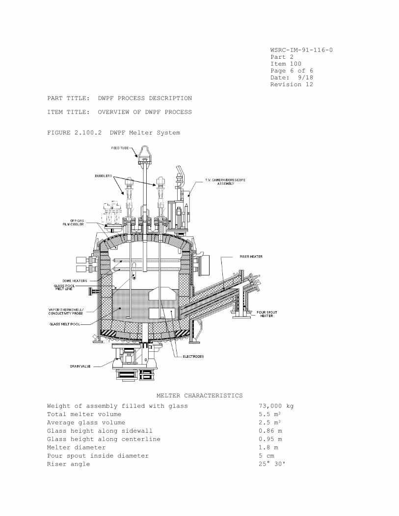
Vitrification of SRS waste is accomplished in a slurry-fed, Joule-heated
melter (Figure 2.100.2). The feed slurry is introduced from the top of the
melter. It forms a crust, or cold cap, on the surface of the melt pool as the
water evaporates from the feed slurry, and is removed via the off-gas system.
Two pairs of diametrically-opposed electrodes supply electric power directly
to the melt. The nominal glass temperature beneath the cold cap is 1150°C,
but varies throughout the melter. The cold cap melts from the bottom and
forms the borosilicate waste glass matrix. For a nominal pour rate of 100
kg/hr, and a nominal glass melt weight of 6500 kg in the melter, the average
residence time in the melter is about 65 hours. The dome of the melter
contains four pairs of metal resistance lid heaters that are used to provide
the heat for startup, as well as supplemental heat during glass production.
Canister Filling
Glass is normally removed from near the bottom of the DWPF melter through a
riser and pour spout (Figure 2.100.2). The canister, on the pour turntable,
is connected to the melter by a bellows assembly, which seals the canister-

WSRC-IM-91-116-0
Part 2
Item 100
Page 3 of 6
Date: 9/18
Revision 12
PART TITLE: DWPF PROCESS DESCRIPTION
ITEM TITLE: OVERVIEW OF DWPF PROCESS
pour spout connection. Pouring is accomplished by drawing a vacuum on the
pour spout relative to the melter. Canister filling is monitored by an
infrared level detection system. When the desired level of fill in the
canister is achieved, pouring is stopped by equalization of the pressure
between the melter and the pour spout. After pouring is stopped, venting of
the canister to the off-gas system is continued. The canister is then rotated
from beneath the pour spout. The canister is then temporarily sealed (ICC)
with a tapered plug that shrink-seals as cooling continues, creating a
leaktight seal of better than 2 x 10⁻⁴ atm-cc He/sec.
Canister Decontamination
Frit slurry blasting is used to remove contamination and metal oxides from the
canister surface. As the canister rotates through a helical path in an
enclosed chamber, jets blast all exposed surfaces with an aqueous slurry of
glass frit. After canister decontamination, the used frit slurry (containing
the contamination from the canister surface) is sent to the SME for melter
feed preparation.
Final Canister Closure
The canister is sealed by upset resistance welding a nominal 12.89 cm diameter
plug into the canister nozzle. After canister decontamination and drying, the
temporary seal is pushed down in the canister neck, exposing clean metal for a
permanent plug weld. The plug, which is slightly larger in diameter than the
nozzle bore and has a tapered edge, is centered in the nozzle. The canister
is supported by its flange on the welder bottom electrode, then the upper
electrode is lowered onto the plug. As a force of 90,000 lbs (400,000
newtons) is applied to the plug, a current of 250,000 amperes is passed
through the plug and nozzle. The 40 cm line of contact is heated (but not
melted), the plug is forced into the nozzle, and a 1-cm thick, solid state
weld is made in 1.5 seconds. The weld produced is sufficiently leaktight to
meet specification 2.2 (based on experimental evidence the weld is leaktight
to approximately 1 x 10⁻⁹ atm-cc He/sec, and of comparable strength to the
base metal).
Interim Storage
The filled, decontaminated, and sealed canisters are moved by a shielded
transport vehicle and stored in the Glass Waste Storage Buildings (GWSBs). In
both GWSBs, air is circulated across the canisters' surfaces by natural
convection to prevent overheating of the building and to keep the canisters
cool. Current plans include the double stacking of canisters in GWSB#1 to
allow for additional canister storage.
References

WSRC-IM-91-116-0
Part 2
Item 100
Page 4 of 6
Date: 9/18
Revision 12
PART TITLE: DWPF PROCESS DESCRIPTION
ITEM TITLE: OVERVIEW OF DWPF PROCESS
1. R. Maher, L. F. Shafranek, J. A. Kelley, and R. W. Zeyfang,
"Solidification of the Savannah River Plant High-Level Waste", American
Nuclear Society Trans., 39, p. 228, 1981.
2. M. D. Boersma, "Process Technology for the Vitrification of Defense High-
Level Waste at the Savannah River Plant", American Nuclear Society - Fuel
Reprocessing and Waste Management proceedings, 1, p. 131-47, 1984.
3. R. G. Baxter, "Design and Construction of the Defense Waste Processing
Facility Project at the Savannah River Plant", Waste Management '86, 2, High-
Level Waste, p. 449, 1986.
4. R. G. Baxter, Defense Waste Processing Facility Wasteform and Canister
Description, USDOE Report DP-1606, Revision 2, E. I. DuPont de Nemours and
Co., Inc., Savannah River Plant, Aiken, SC 19808 (1988).
5. A. F. Weisman, L. M. Papouchado, J. R. Knight, D. L. McIntosh, "High Level
Waste Vitrification at the Savannah River Plant," Waste Management 88, 2, Roy
G. Post (ed.), 203-10 (1988).

WSRC-IM-91-116-0
Part 2
Item 100
Page 6 of 6
Date: 9/18
Revision 12
PART TITLE: DWPF PROCESS DESCRIPTION
ITEM TITLE: OVERVIEW OF DWPF PROCESS
FIGURE 2.100.2 DWPF Melter System
MELTER CHARACTERISTICS
Weight of assembly filled with glass 73,000 kg
Total melter volume 5.5 m3
Average glass volume 2.5 m3
Glass height along sidewall 0.86 m
Glass height along centerline 0.95 m
Melter diameter 1.8 m
Pour spout inside diameter 5 cm
Riser angle 25° 30'

WSRC-IM-91-116-0
Part 3
Item 100
Page 1 of 8
Date: 3/06
Revision 8
PART TITLE: WASTE FORM SPECIFICATIONS
ITEM TITLE: 1.1.1 CHEMICAL COMPOSITION PROJECTIONS
1.1 CHEMICAL SPECIFICATION The waste form is borosilicate waste glass.
1.1.1 Chemical Composition Projections In the WQR, the Producer shall project the chemical composition, identify crystalline phases expected to be present, and project the amount of each crystalline phase, for each waste type. The method to obtain the required data shall be described by the producer in the WCP. The data shall be provided in the WQR. Waste form compositions not available for reporting in the initial WQR shall be included in an addendum to the WQR.
Compliance Strategy
A set of projected glass compositions will be defined, which will span the
range of properties of glasses expected to be produced in the DWPF. The
projected compositions will be defined based on the compositions of wastes
currently stored in the Tank Farms at SRS, anticipated blending schemes for
the wastes in the Tank Farm, hypothetical waste compositions, and the expected
composition(s) of the glass frit to be used. Among these compositions, a
credible "worst case" will also be included. Each sludge batch from the Tank
Farm will constitute a waste type for compliance with this specification.
The range of glass compositions will be of a broad nature because of the
uncertainties in the assumptions needed to develop the specified projections.
These estimates will take into account all of the information available at the
time they are made, but will not necessarily reflect the composition of any
particular waste forms subsequently produced. However, it is anticipated that
the range of properties (processing properties, durability as measured by the
Product Consistency Test, crystallization behavior, and waste solubility) of
compositions projected as above will encompass those of all glasses produced
in the DWPF. If future site processes significantly change so that the
composition of the waste would produce a glass whose properties might fall
outside the range spanned by the projected compositions, then the composition
(and properties) of glass to be made from the new waste will be projected in
the same manner as for current waste compositions. The qualification of new
compositions is discussed further in Part 3, Items 500 and 600.
Glasses representing each of the projected compositions will be exposed to the
range of thermal conditions expected during filling and cooling of the DWPF
canister. For each projected composition, the crystalline phases formed will
be identified, and their content determined.
Implementation
The plan being followed to satisfy this specification is outlined in Figure
3.100.1. The plan includes the following elements:
WSRC-IM-91-116-0
Part 3
Item 100
Page 3 of 8
Date: 3/06
Revision 8
PART TITLE: WASTE FORM SPECIFICATIONS
ITEM TITLE: 1.1.1 CHEMICAL COMPOSITION PROJECTIONS
Waste Blending
Feed to the DWPF will be prepared in the SRS Tank Farms, by SRS Waste
Management Operations. The feed preparation steps include sludge washing and
aluminum removal. Waste Management Operations has developed a waste blending
strategy which is intended to:
• Minimize dose rate in the DWPF, and in the process for disposal of
decontaminated salt.
• Empty the oldest tanks as soon as possible.
• Balance waste types in the DWPF feed, to dampen changes in composition.
The waste blending strategy is further constrained by the connections among
the waste tanks.
Each sludge batch is assumed to be a "waste type" for purposes of compliance
with this specification. Each sludge batch will provide feed to the DWPF for
two to three years. The associated salt compositions which will be processed
at the same time are used to define the projected glass compositions. In this
way, the blending strategy has been used to develop the projected glass
compositions.
Hypothetical Waste Compositions
Accurate projection of the chemical composition of future waste is difficult
because of possible SRS nuclear materials production processing changes which
could affect waste generation. The compositions of wastes to be generated in
the future have been estimated based on historical usage of process chemicals,
but modified to reflect current practices in the waste generating processes.
The extremes of HM sludges and Purex sludges have been used as hypothetical
compositions which may represent future waste generation. Three waste
compositions have been generated to serve as input for initial composition
projections. They are:
• A blend of HM wastes. This waste reflects current reprocessing practices.
• A blend of Purex wastes. This waste reflects current reprocessing
practices.
• The DWPF Design-Basis waste (see Part 1, Item 300), designated "Blend."
Each of these is assumed to be a "waste type" for purposes of compliance with
the specification.
Frit
On a weight basis, DWPF glass will nominally consist of 64 wt% borosilicate
glass frit and 36 wt% oxides from sludge/salt effluents (see Part 2, Item
100). The glass-former composition for the DWPF has been developed so that
DWPF waste glass will have similar properties to simulated waste glasses

WSRC-IM-91-116-0
Part 3
Item 100
Page 4 of 8
Date: 3/06
Revision 8
PART TITLE: WASTE FORM SPECIFICATIONS
ITEM TITLE: 1.1.1 CHEMICAL COMPOSITION PROJECTIONS
previously developed for sludge-only processing. This has been achieved by
modifying the glass frit composition to take into account changes in waste
processing. Properties which are controlled through modification of frit
composition are chemical durability of the glass, solubility of waste in the
glass-former, thermal stability of the glass, and reliability of processing
behavior and product properties.
Flowsheet Model
An integrated flowsheet computer model was used to develop the material
balance for design of the DWPF at SRS. This computer model has been
modified to incorporate recent modifications of both the DWPF process, and of
SRS processes which produce high-level waste. This model has been used to
estimate the nominal average compositions of waste glass that will be produced
in the DWPF, based on projections of both current and future waste. The model
takes into account
• Sludge and salt effluent compositions which are fed to the DWPF.
• The Tank Farm waste blending strategy.
• Reactions in the DWPF which alter the chemistry of the feed streams.
• Available lead time for adjustments to the feed.
• Frit composition.
The reaction chemistry used in the model is based on data obtained in tests
using non-radioactive waste simulants. Data from both laboratory and
engineering-scale equipment have been incorporated in the model. When
possible, these tests have been augmented by laboratory experiments using
radioactive waste from the existing inventory.
The model has been used to generate the projected chemical compositions of
four waste glasses to be produced from existing high-level waste inventory.
These glasses represent the expected compositions to be produced in the DWPF
through at least the first ten years of operation. The compositions of these
four glasses (Batches 1-4) are shown in Table 3.100.1. Also represented in
this table are three hypothetical glass compositions produced from:
• A glass based on the Design-Basis waste (see Part 1, Item 300), designated
"Blend."
• A glass based on HM wastes that represents the upper design limit of glass
viscosity that will be produced at DWPF.
• A glass based on Purex wastes that represents the lower design limit of
glass viscosity that will be processed at DWPF. This glass composition is
based on the following assumptions: maximum salt feed rate to the DWPF,
minimum sludge feed rate, minimal removal of soluble salts during sludge
processing in the Tank Farm, and use of a frit higher in alkali than the frit
which will be used initially in the DWPF. Thus, it represents a possible,
though unlikely, worst-case composition.

WSRC-IM-91-116-0
Part 3
Item 100
Page 5 of 8
Date: 3/06
Revision 8
PART TITLE: WASTE FORM SPECIFICATIONS
ITEM TITLE: 1.1.1 CHEMICAL COMPOSITION PROJECTIONS
Crystalline Phases
Prototypic DWPF canisters have been instrumented with thermocouples and filled
under both expected conditions and likely process upset conditions. The
thermal profile during filling and cooling was recorded. Several canisters
were filled to determine the variability in the thermal profile.
Samples of simulated waste glass of each of the projected compositions will be
subjected to the thermal conditions determined from the prototypic canisters,
both at the surface of the canister (approximating quenched conditions) and
along the centerline (probable worst-case conditions). Crystalline phases
generated from these heat treatments will be identified, and the amount of
each quantified, using scanning electron microscopy and x-ray diffraction.
Qualification of Future Waste Glass Compositions
When future waste compositions are identified, glasses will be formulated for
those compositions which will satisfy all of the production-related
specifications (e.g., the criterion in Part 3, Item 500). These glasses will
also be subjected to the thermal conditions determined from the prototypic
canisters as is currently being done for the projected compositions in Table
3.100.1. The results of these studies will be submitted to the repository
program as an addendum to the WQR.
Documentation
The Waste Form Qualification Report will detail the development of the
projected glass compositions, and the compositions themselves. The expected
temperature profiles of canisters during filling and cooling will be provided.
The results of exposing samples representative of each projected glass to the
expected thermal profile will be reported, including the identity and amount
of any crystalline phases formed.
References
1. J. A. Stone, J. A. Kelley, and T. S. McMillan, Sampling and Analysis of Savannah River Plant High-Level Waste Sludges, USERDA Report DP-1399, E. I. DuPont de Nemours and Co., Inc., Savannah River Plant, Aiken, SC 29808 (1976).
2. J. A. Stone, Separation of SRP Waste Sludges and Supernates, USERDA Report DP-1441, Revision 1, E. I. DuPont de Nemours and Co., Inc., Savannah River
Plant, Aiken, SC 29808 (1976).
3. R. S. Ondrejcin, Chemical Composition of Supernates Stored in SRP High-Level Waste Tanks, USAEC Report DP-1347, Revision 1, E. I. DuPont de Nemours and Co., Inc., Savannah River Plant, Aiken, SC 29808 (1974).
4. L. W. Gray, M. Y. Donnan, B. Y. Okamoto, Chemical Characterization of SRP Waste Tank Sludges and Supernates, USDOE Report DP-1483, E. I. DuPont de Nemours and Co., Inc., Savannah River Plant, Aiken, SC 29808 (1979).

WSRC-IM-91-116-0
Part 3
Item 100
Page 6 of 8
Date: 3/06
Revision 8
PART TITLE: WASTE FORM SPECIFICATIONS
ITEM TITLE: 1.1.1 CHEMICAL COMPOSITION PROJECTIONS
5. R. G. Baxter, Description of Defense Waste Processing Facility Reference Waste Form and Canister, USDOE Report DP-1606, Revision 1, E. I. DuPont de Nemours and Co., Inc., Savannah River Plant, Aiken, SC 29808 (1983).
6. P. D. Soper, D. D. Walker, M. J. Plodinec, G. J. Roberts, and L. F.
Lightner, "Optimization of Glass Composition for the Vitrification of Nuclear
Waste at the Savannah River Plant," Bull. Am. Cer. Soc., 62, 1013-8 (1983).
7. M. J. Plodinec, "Vitrification Chemistry and Nuclear Waste," J. Non-Cryst. Solids, 84, 206-14 (1986).
8. C. M. Jantzen, "Systems Approach to Nuclear Waste Glass Development," J. Non-Cryst. Solids, 84, 215-25 (1986).
9. J. R. Fowler, et al., "Large-Scale Process Simulation - A Case Study,
Integrated Waste Processing Flowsheet for the Savannah River Site," USDOE
Report WSRC-RP-89-1018, Westinghouse Savannah River Co., Aiken, SC 29802
(1989).
10. Basic Data Report for the Defense Waste Processing Facility, Revision 139, USDOE Report WSRC-RP-92-1186 (1992).

WSRC-IM-91-116-0
Part 3
Item 100
Page 7 of 8
Date: 3/06
Revision 8
PART TITLE: WASTE FORM SPECIFICATIONS
ITEM TITLE: 1.1.1 CHEMICAL COMPOSITION PROJECTIONS
TABLE 3 . 100 . 1 Pr o j e c t e d DWPF Wa s t e Gl a s s Compos i t i ons .
GLASS CONSTITUENT SLUDGE TYPE COMPOSITION
(weight %) Blendd Batch 1 Batch 2 Batch 3 Batch 4 HM Purexw
Al2O3 3.97 4.85 4.44 3.24 3.30 7.06 2.88
B2O3 7.98 7.66 7.68 7.68 8.07 6.92 10.17
BaSO4 0.27 0.22 0.24 0.26 0.38 0.18 0.29
CaO 0.96 1.16 0.99 0.92 0.82 1.00 1.01
CaSO4 0.08 0.12 0.11 0.10 0.0034 trace 0.12
Cr2O3 0.12 0.10 0.12 0.13 0.14 0.085 0.14
Cs2O 0.12 0.079 0.081 0.079 0.14 0.073 0.080
CuO 0.44 0.40 0.41 0.40 0.46 0.25 0.42
Fe2O3 10.37 12.47 10.57 11.12 11.28 7.36 12.69
Group Aa 0.14 0.10 0.14 0.10 0.20 0.20 0.077
Group Bb 0.36 0.22 0.44 0.25 0.60 0.89 0.083
K2O 3.85 3.47 3.49 3.46 3.98 2.13 3.57
Li2O 4.38 4.40 4.40 4.40 4.31 4.61 3.10
MgO 1.35 1.36 1.35 1.35 1.38 1.45 1.33
MnO 2.02 2.05 1.62 1.81 3.06 2.07 1.98Na2O 8.70 8.58 8.58 8.48 8.85 8.15 12.09
Na2SO4 0.10 0.10 0.12 0.095 0.13 0.14 0.12
NaCl 0.19 0.31 0.23 0.22 0.089 0.092 0.26
NiO 0.88 0.74 0.89 1.06 1.08 0.40 1.21
SiO2 50.01 49.61 50.00 49.81 49.09 54.26 44.39
ThO2 0.19 0.36 0.62 0.76 0.24 0.55 0.011
TiO2 0.89 0.65 0.66 0.65 1.01 0.55 0.64
U3O8 2.13 0.53 2.29 3.14 0.78 1.01 2.88
TOTALz
99.50 99.54 99.47 99.52 99.39 99.43 99.54
a Group A: isotopes of Tc, Se, Te, Rb, Mo.
b Group B: isotopes of Ag, Cd, Cr, Pd, Tl, La, Ce, Pr, Pm, Nd, Sm, Tb, Sn, Sb, Co, Zr, Nb, Eu, Np, Am, Cm.
d The "Blend" is the current DWPF Design-Basis glass (see the Glossary - Part 1, Item 300).
w The "Purex" glass is a possible "worst-case" composition.
z The Minor components constitute the difference between indicated total and 100%.


WSRC-IM-91-116-0
Part 3
Item 200
Page 1 of 8
Date: 9/18
Revision 12
PART TITLE: WASTE FORM SPECIFICATIONS
ITEM TITLE: 1.1.2 CHEMICAL COMPOSITION DURING PRODUCTION
1.1.2 Chemical Composition During Production
In the Production Records, the Producer shall report the oxide composition of
the waste form. The reported composition shall include all elements,
excluding oxygen, present in concentrations greater than 0.5 percent by weight
of the glass, for each waste type. The Producer shall describe the method to
be used for compliance in the WCP. An estimate of the error of the reported
composition and the basis for the estimate shall be reported in the WQR.
Compliance Strategy
The DWPF’s strategy for determining the chemical composition of DWPF glass
during production (shown in Figure 3.200.1) is based on the relatively
constant nature of the sludge feed to the DWPF over the life of each Tank Farm
sludge batch, and of the salt effluent feed to the DWPF over the life of each
Tank Farm salt effluent batch. Thus, for purposes of compliance with the
specification, a macro-batch (see Part 1, Item 300) constitutes a waste type.
Samples from each Tank Farm sludge and salt batch (which together constitute
the macro-batch) will be analyzed by SRNL to identify the elements which must
be reported for compliance purposes (those present in the glass at > 0.5 wt%).
This will be done by identifying all elements present in either the sludge or
the salt effluent at greater than 1 wt% which would survive vitrification (see
Table 3.200.1). While the representativeness of individual Tank Farm samples
cannot be demonstrated, SRS's experience with analyses of samples from the
Tank Farm indicates that the range of analytical results for samples from a
single tank is less than 30% for major elements. Thus, by choosing a
conservative value based on Tank Farm sample analyses, the DWPF is assured of
reporting all major species.
During processing of each macro-batch in the DWPF, the DWPF laboratory will
analyze samples from each process batch in the SME (see Part 1, Item 300) to
determine the actual content of the reportable elements identified from the
Tank Farm samples. These results will then be used by the DWPF to calculate
the chemical composition of the glass, which will be reported in the
Production Records. The composition for each of the canistered waste forms
produced by a macro-batch will be reported as average values for each
component for the entire macro-batch. Standard deviations will also be
appropriately calculated and reported for each component for each macro-batch,
based on the entire set of analyses performed on process batches.
The errors associated with this strategy will be characterized during the DWPF
Startup Test Program, when feed and glass samples will be routinely taken and
analyzed in the DWPF. The precision and accuracy of the determination of the
glass composition will be calculated based on the results of the DWPF Startup
Test Program, and will be reported in the Waste Form Qualification Report.
Preliminary estimates based on SRNL experience with similar equipment are also
provided in the WQR.

WSRC-IM-91-116-0
Part 3
Item 200
Page 2 of 8
Date: 9/18
Revision 12
PART TITLE: WASTE FORM SPECIFICATIONS
ITEM TITLE: 1.1.2 CHEMICAL COMPOSITION DURING PRODUCTION
During each sludge batch at least one glass sample will be taken from the
glass pour stream as it enters the canister and archived at the SRNL Shielded
Cells Facility per standard procedure. Analysis of the sample will be
performed at the request of DWPF.
Implementation
The tasks planned to satisfy this specification are outlined in Figure
3.200.2. They are:
• Development of equipment and methods to sample the slurry feed material in the DWPF process vessels.1
• Development of methods for analyses of the major components in each process batch.2-6 This includes demonstration of these methods in the laboratory
with non-radioactive simulants, and in remote facilities with actual
radioactive waste.
• Conversion of the analytical methods into procedures for use in the DWPF itself.
• Development of a relationship between feed composition and glass composition.
• Estimation of the error in the reported composition. This activity will be performed as part of the Startup Test Program, and will be based on analyses
of the components of the error, and on comparisons of the reported
composition (based on analyses of feed material) to the actual composition
of the glass.
• Development of analytical methods for samples of production glass.
Sampling of Feed Material from Process Vessels
In the DWPF, feed material will be pumped out of each process vessel, through
a recirculating sample loop, and back into the process vessel. This
recirculating loop carries feed material from the process vessel in the canyon
cell to the DWPF laboratory. The recirculating loop limits the amount of
radioactive material in the laboratory, while still providing a sample which
is representative of the contents of the process vessel.
To take a sample, a portion of the feed from the recirculating loop is
diverted into a sampling container in the laboratory. The sampling container
is then removed, and the contents prepared for analysis.

WSRC-IM-91-116-0
Part 3
Item 200
Page 3 of 8
Date: 9/18
Revision 12
PART TITLE: WASTE FORM SPECIFICATIONS
ITEM TITLE: 1.1.2 CHEMICAL COMPOSITION DURING PRODUCTION
Analysis of Feed Material
Samples of melter feed slurry can be prepared for analysis using one of two
methods. The samples will either be converted to glass and then analyzed or
the slurry will be directly analyzed without vitrification. After
vitrification of the melter feed slurry, the vitrified sample is dissolved for
analyses. For samples analyzed without vitrification (i.e., direct analysis
method), the slurries are dissolved and then analyzed. For these analyses a
vitrification factor for conversion to a glass basis will be utilized. The
primary analysis technique to be used is Inductively Coupled Plasma – Atomic
Emission Spectroscopy (ICP-AES).
Waste Form Qualification Report (WQR) Volume 2 will contain descriptions of
each of the analytical methods. Demonstrations of their application on non-
radioactive simulants, and in remote facilities on actual radioactive waste
slurries and glasses, by SRNL, will also be reported. Simulant and
radioactive testing of the direct analysis method will also be reported.
Additionally, a level of confidence will be established that the two
analytical methods provide comparable results under production conditions
(i.e., side-by-side testing). The DWPF will continually evaluate (and modify,
as necessary) each of the methods used in the DWPF laboratory.
Because of the importance of glass composition, the DWPF laboratory has
instituted a rigorous quality assurance and control program for slurry
sampling and analyses. This is described in more detail in the glass product
control program description (see Part 3, Item 500). The objectives of the
program are to ensure the accuracy of the analytical values reported, and to
control the precision so that it is within expected values.
Glass standards will be frequently analyzed. Calibration standards for
analytical methods will be materials which are traceable to the National
Institute of Science and Technology (NIST) or to other nationally recognized
sources.
Feed to Glass Correlation
The DWPF will report the chemical composition of the glass based on analyses
of melter feed samples from the SME. Because the feed samples are vitrified
prior to analysis or converted to a vitrified basis using a vitrification
factor, analyses of feed samples are actually analyses of equivalent glass
samples. Thus, the DWPF assumes that analysis of feed samples is equivalent
to analysis of glass leaving the melter.
During production, the composition of canistered waste forms produced during
processing of a macro-batch will be reported as the average of the analyses of
vitrified feed samples from all the process batches produced from that macro-
batch. This introduces an error by neglecting the heels from previous batches
left in process vessels. The magnitude of this error will be determined
during the Startup Test Program.

WSRC-IM-91-116-0
Part 3
Item 200
Page 4 of 8
Date: 9/18
Revision 12
PART TITLE: WASTE FORM SPECIFICATIONS
ITEM TITLE: 1.1.2 CHEMICAL COMPOSITION DURING PRODUCTION
During the Startup Test Program, the DWPF will attempt to reliably predict the
composition of the glass in individual canisters from feed analyses. The SME,
MFT, and melter are each expected to act as well-stirred vessels for normal
operating conditions. However, when large changes in feed composition occur
(e.g., changing from Purex to HM feed), material flow through the melter may
change to plug flow.
Estimates of Error of Reported Composition
During production, the DWPF will report the chemical composition of the glass
from a macro-batch based on analyses of melter feed samples from the SME
batches produced from that macro-batch. This introduces an error by neglecting
the heels from previous batches left in process vessels. This source of error
along with other sources of error will be characterized during the Startup
Test Program and reported in Volume 2 of the WQR.
The reported composition will be subject to the following sources of error:
• Feed non-uniformity
• Sampling variability
• Variability due to the analytical system
• Error in calculation of macro-batch composition
• Process variability
Glass Sampling
At least one glass pour stream sample will be taken by DWPF during the
processing of each sludge batch, analyzed as necessary and archived at the
SRNL Shielded Cells Facility. These samples may be characterized at the
request of DWPF should additional testing requirements be identified in the
future but are no longer required for batch sampling confirmation.
Startup Test Program
During the Startup Test Program (see Appendix 1.200.3), statistically designed
tests will be performed to estimate the error in the reported composition. A
major goal of the tests will be to determine quantitatively how well the
macro-batch average for each element (determined from feed samples) represents
the contents of actual canisters of glass. The reported glass composition,
based on analyses of feed material, will also be compared to analyses of
samples of glass taken from canisters. Long-term and short-term variability
will be characterized in a statistically defensible manner and the results
reported in Volume 2 of the WQR.
WSRC-IM-91-116-0
Part 3
Item 200
Page 5 of 8
Date: 9/18
Revision 12
PART TITLE: WASTE FORM SPECIFICATIONS
ITEM TITLE: 1.1.2 CHEMICAL COMPOSITION DURING PRODUCTION
Documentation
The Waste Form Qualification Report Volume 2 will describe the slurry sampling
system and the analytical methods for determining the glass composition during
production. Reports of the results of experimental tests of the methods will
also be included. Estimates of the errors due to process batch non-
uniformity, sampling, analyses, and process variability will be provided from
pilot plant testing, testing with simulated feeds in the laboratory and remote
testing using radioactive materials. Determinations of the precision and
accuracy of the DWPF laboratory procedures will also be reported.
The Production Record for each canistered waste form will include the
elemental composition of the glass. The values reported will be based on the
numerical averages of the individual elemental analyses for all of the process
batches corresponding to the macro-batch, expressed as oxides in the glass.
The number of samples averaged, and the standard deviations, appropriately
calculated, of the analytical values for each element, will also be reported.
The reported chemical composition will be the same for all canistered waste
forms produced from a given macro-batch of feed.
References
1. D. E. Snyder and D. L. Gunnels, "Remote Operation of Defense Waste
Processing Facility Sampling Stations," Proceedings, 33rd Conference on Remote
Systems Technology, American Nuclear Society, 90-93 (1985).
2. C. J. Coleman, R. A. Dewberry, A. J. Lethco, C. D. Dennard, "Analytical
Methods and Laboratory Facility for the Defense Waste Processing Facility,"
Proceedings - 28th Oak Ridge National Laboratory Conference on Analytical
Chemistry, W. R. Laing (ed.), Lewis Publishers, Chelsea, MI, 337-43 (1986).
3. C. J. Coleman, "Analyses of Nuclear Fuel and High-Level Waste by
Inductively Coupled Plasma-emission Spectroscopy," Analytical Spectroscopy, W.
S. Lyon (ed.), Elsevier, New York, 195-99 (1986).
4. C. J. Coleman, E. W. Bauman, N. E. Bibler, R. A. Dewberry and E. F.
Sturcken, Analysis of Radioactive Waste and Glass for a Defense Waste
Solidification Plant, USDOE Report DP-MS-87-23, E. I. DuPont de Nemours & Co.,
Savannah River Laboratory, Aiken, SC 29808 (1987).
5. C. J. Coleman, N. E. Bibler, R. A. Dewberry, "Analysis of High Level
Radioactive Glasses and Sludges for the Savannah River Site," Waste
Management 90, 2, Roy G. Post (ed.), 651-7 (1990).
6. R.S. Beck, et al., Results of Scoping Work for Insert Use at DWPF, USDOE
Report WSRC-TR-97-0076, Westinghouse Savannah River Company, Aiken, SC 29808
(1997).

WSRC-IM-91-116-0
Part 3
Item 200
Page 6 of 8
Date: 9/18
Revision 12
PART TITLE: WASTE FORM SPECIFICATIONS
ITEM TITLE: 1.1.2 CHEMICAL COMPOSITION DURING PRODUCTION
TABLE 3.200.1 Major Elements (> 0.5 wt % of the glass) and Source of those
Elements
Component Source
Al Sludge
B Frit
Ca Sludge
Fe Sludge
Li Frit
Mg Frit, sludge
Mn Sludge
Na Frit, MST, sludge
Ni Sludge
Si Frit, sludge
Ti MST
U Sludge
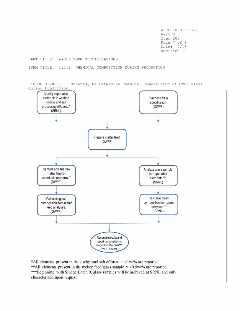
WSRC-IM-91-116-0
Part 3
Item 200
Page 7 of 8
Date: 9/18
Revision 12
PART TITLE: WASTE FORM SPECIFICATIONS
ITEM TITLE: 1.1.2 CHEMICAL COMPOSITION DURING PRODUCTION
FIGURE 3.200.1 Strategy to Determine Chemical Composition of DWPF Glass
during Production.
Identify reportable
elements in washed
sludge and salt
processing effluents.*
(SRNL)
Purchase frit to
specification
(DWPF)
Reconcile results and
report composition in
Production Records***.
(DWPF & SRNL)
*All elements present in the sludge and salt effluent at >1wt% are reported
**All elements present in the melter feed/glass sample at >0.5wt% are reported.
***Beginning with Sludge Batch 9, glass samples will be archived at SRNL and only
characterized upon request.
Prepare melter feed.
(DWPF)
Sample and analyze
melter feed for
reportable elements.**
(DWPF)
Analyze glass sample
for reportable
elements.***
(SRNL)
Calculate glass
composition from melter
feed analyses.
(DWPF)
Calculate glass
composition from glass
analyses.***
(SRNL)

WSRC-IM-91-116-0
Part 3
Item 200
Page 8 of 8
Date: 9/18
Revision 12
PART TITLE: WASTE FORM SPECIFICATIONS
ITEM TITLE: 1.1.2 CHEMICAL COMPOSITION DURING PRODUCTION
FIGURE 3.200.2 Tasks planned to satisfy Specification 1.1.2, Chemical
Composition during Production.
Develop feed sampling
techniques.
(SRNL)
Determine analytical
methods for feed
(SRNL)
Determine procedures
to determine DWPF glass
composition
(SRNL)
Estimate errors in
reported composition
from Startup Test
Programs. (DWPF)
Develop relationship
between feed and glass
composition.
(SRNL)
DWPF
Hot
Startup
Report glass
composition
based on melter
feed. (DWPF)
Confirm report glass
composition using melter
samples.* (SRNL)
*Beginning with Sludge Batch 9, glass samples will be archived at SRNL and
only characterized upon request.

WSRC-IM-91-116-0
Part 3
Item 300
Page 1 of 8
Date: 3/06
Revision 8
PART TITLE: WASTE FORM SPECIFICATIONS
ITEM TITLE: 1.2.1 RADIONUCLIDE INVENTORY PROJECTIONS
1.2 RADIONUCLIDE INVENTORY SPECIFICATION The Producer shall report the inventory of radionuclides (in Curies) that have half-lives longer than 10 years and that are, or will be, present in concentrations greater than 0.05 percent of the total radioactive inventory for each waste type, indexed to the years 2015 and 3115. 1.2.1 Radionuclide Inventory Projections The Producer shall provide in the WQR estimates of the total quantities of individual radionuclides to be shipped to the repository, for each waste type. The Producer shall also report the upper limit of these radionuclides for any canistered waste form, and an average calculated radionuclide inventory per canister for each waste type. The method to be used to obtain the required data shall be described by the Producer in the WDP. The data shall be provided in the WQR. Radionuclide inventory estimates not available for reporting in the initial WQR shall be included in an addendum to the WQR.
Compliance Strategy
The DWPF Design-Basis waste glass will be used to identify the set of
radionuclides to be reported. Each sludge batch from the Tank Farm will
constitute a waste type for compliance with this specification. Estimates of
both the total concentrations of individual radionuclides and the average
concentration per canister will be developed for each of the waste types which
will actually be vitrified in the DWPF. Estimates of the total quantities of
individual radionuclides in DWPF glass will be based on the sum of the
inventories of individual radionuclides currently stored in the waste tanks,
and on anticipated future waste generation at SRS. For the latter, the
radionuclide inventory of the Design-Basis glass will be assumed. For each
radionuclide, the highest value of the concentration per canister for any
waste type will be reported as the upper limit for any canistered waste form.
Each estimated value will be indexed to both 2015 and 3115.
Implementation
The tasks planned to satisfy this specification are outlined in Figure
3.300.1. These tasks are:
Development of the radionuclide inventory for the Design-Basis glass. The
Design-Basis glass represents an upper bound in terms of the dose rate, and
heat generation rate, expected from DWPF canistered waste forms.
Use of the radionuclide inventory of the Design-Basis glass to identify the
set of radionuclides whose inventory must be reported.

WSRC-IM-91-116-0
Part 3
Item 300
Page 2 of 8
Date: 3/06
Revision 8
PART TITLE: WASTE FORM SPECIFICATIONS
ITEM TITLE: 1.2.1 RADIONUCLIDE INVENTORY PROJECTIONS
Identification of the amounts of individual radionuclides in waste
currently stored in the Tank Farm. As of December 31, 1991, it was estimated
that the high-level waste (HLW) tanks at SRS contained 34,784,000 gallons of
waste. The estimated curie content of the current waste inventory is listed
in Table 3.300.1.
Identification of the waste types for waste currently stored at SRS. As
discussed in Part 3, Item 100, these waste types correspond to the sludge
batches in the Tank Farm, and their associated batches of salt.
Estimation of the number of canisters produced in the future by SRS. This
estimate will include future waste generation from nuclear materials
production at SRS, as well as aqueous wastes from DWPF operations.
Estimation of the total amount of radionuclides for each waste type. For
future waste, the Design-Basis composition will be used. The total quantity
to be shipped to the repository will be assumed to be the sum of the totals
for each waste type.
Determination of an upper bound for the concentration of each radionuclide
in DWPF canistered waste forms.
Design-Basis Radionuclide Inventory
Using the radionuclide inventory of the Design-Basis waste (Part 1, Item 300),
and the integrated flowsheet model for the DWPF (Part 3, Item 100), the
radionuclide inventory of the Design-Basis glass has been developed. This
inventory has been used as the basis for biological shielding, process
cooling, and environmental release requirements for the DWPF. Several
assumptions were made in developing the design basis radionuclide inventory.
A standard blend of waste streams containing various radionuclides was
developed, and assumed to be the constant input to the DWPF.
Insoluble waste (sludge) is aged five years to decay short-lived isotopes.
Soluble waste (feed for precipitation process) is aged 15 years, primarily
to assure low concentrations of Ru-106.
The Design-Basis glass does not necessarily represent an upper bound for the
concentration of any specific radionuclide. However, it is expected that it
will provide an upper bound for many of the radionuclides because actual waste
types in the SRS Tank Farm have been aged for longer periods (10 – 35 years)
than the Design-Basis glass. Thus, concentrations of radionuclides with
intermediate half-lives (Cs-137, Sr-90) in the Design-Basis glass should be
higher. In addition, since the Design-Basis glass is the basis for design of
the shielding for the DWPF, higher total concentrations of radionuclides
emitting penetrating radiation are precluded by administrative controls.
Unfortunately, there is very little data about the concentrations of many of
the radionuclides in Table 3.300.2 in actual waste. However, any other

WSRC-IM-91-116-0
Part 3
Item 300
Page 3 of 8
Date: 3/06
Revision 8
PART TITLE: WASTE FORM SPECIFICATIONS
ITEM TITLE: 1.2.1 RADIONUCLIDE INVENTORY PROJECTIONS
assumption about the upper bound would require speculation about the nature of
future waste types, or divulgence of classified information. If the
projections of the radionuclide inventories indicate that the concentrations
of specific radionuclides in some specific waste type exceed those in the
Design-Basis glass, then the maximum concentrations for that waste type will
be reported in Volume 3 of the Waste Form Qualification Report (WQR) as the
upper limit.
Radionuclides to be Reported
The radionuclide inventory of the Design-Basis glass includes projections of
the amounts of individual radionuclides as a function of time after production
of the glass. Table 3.300.2 lists all of the radionuclides, with a half-life
greater than ten years, which comprise at least 0.01% of the radionuclide
inventory (in curies) of the Design-Basis glass at any time up to 1100 years
after production. This is the set of radionuclides which will be reported
under this specification. The selection of the 0.01% limit is discussed in
more detail in Part 3, Item 400. Use of this more inclusive limit ensures
that all required radionuclides are reported for compliance with this
specification.
It is not possible to predict when DWPF canistered waste forms will be shipped
to a repository. The DWPF has elected to use the year 2015 as an assumed time
of shipment. Thus, the projections indexed to the year 2015 will be
considered to be those at time of shipment.
Radionuclide Inventory of Current Waste
The waste types designated Batches 1 – 4 in Part 3, Item 100, will be assumed
to be the waste types comprising current waste, for purposes of compliance
with this specification. For each waste type, the total radionuclide
inventory for that waste type will depend on the amounts of individual
radionuclides per unit mass of each waste type, and the total amount of each
waste type in the SRS Tank Farm.
The information sources which will be used to identify the amounts of
individual radionuclides for each waste type will include the results
generated by computer codes based on radionuclide production, analytical data
from waste samples, and results from the DWPF flowsheet calculations (see Part
3, Item 100). Available data from all of the radionuclide inventory sources
will be compared to assure that the most reasonable values are used for each
individual radionuclide. If a good technical basis for choosing one value
over another cannot be established, the most conservative value will be
chosen. As discussed in Part 3, Item 100, waste blending schemes developed by
SRS Tank Farm personnel will be used to develop radionuclide inventory
estimates for current waste.
The total amount of each radionuclide in each waste type will be estimated
based on the volume of the sludge, and a factor to convert from waste volume
to mass. The mass of each waste type will then be used to determine the total
number of canisters to be produced from each waste type.

WSRC-IM-91-116-0
Part 3
Item 300
Page 4 of 8
Date: 3/06
Revision 8
PART TITLE: WASTE FORM SPECIFICATIONS
ITEM TITLE: 1.2.1 RADIONUCLIDE INVENTORY PROJECTIONS
When samples are taken of waste and glass from the initial feed to the DWPF
(Batch 1), the concentration of the radionuclides listed in Table 3.300.2 for
the waste and glass samples will be compared to the projections. These will
provide confirmation of the projected radionuclide inventories.
Future Waste
The radionuclide inventory of the Design-Basis glass will also be used to
project the radionuclide content of waste to be generated in the future. SRS
production forecasts will be used to project the amount of waste to be
generated in the future (and thus the number of canistered waste forms to be
produced in the DWPF). Since the composition of waste to be generated in the
future is not known, the Design-Basis radionuclide inventory will be assumed
for future waste.
Total Amount of Individual Radionuclides in DWPF Glass
The total amount of individual radionuclides in projected DWPF glasses will be
calculated by adding the amount of each radionuclide in all of the canisters
of each waste type for current waste to the amount of that radionuclide
assumed to be produced in the future.
Determination of Upper Limit for each Radionuclide
The specification requires that the DWPF determine an upper limit for each
radionuclide in any canistered waste form. For each radionuclide, the average
radionuclide inventory per canistered waste form for each waste type will be
compared to determine a maximum concentration. This will then be reported as
the upper limit in WQR Volume 3.
Qualification of Future Waste Glass Compositions
Because the radionuclide inventory of the Design-Basis glass was the basis for
design of biological shielding for the DWPF, and for designs of the cooling
systems for the Glass Waste Storage Buildings, it represents an upper bound
expected for all DWPF canistered waste forms. If future wastes would produce
glasses which exceed these properties, or would exceed the upper limit of any
of the radionuclides, the DWPF proposes to apply Part 6, Item 200, in the
following manner.
A determination will be made of whether the new waste composition will
produce a glass with different properties (radionuclide inventory, dose rate,
or heat generation rate) than represented by the set of projected
compositions. The repository program will be notified in writing of the
results of that determination. If the properties of the new glass are bounded
by the set of projected compositions (from above), the DWPF will propose to
update the WQR to include the new composition, but will propose that no
further action be taken. If the waste will produce a glass with properties
outside the range of those already projected, then the DWPF will propose
activities to ensure that the waste produces a glass which complies with
specifications.

WSRC-IM-91-116-0
Part 3
Item 300
Page 5 of 8
Date: 3/06
Revision 8
PART TITLE: WASTE FORM SPECIFICATIONS
ITEM TITLE: 1.2.1 RADIONUCLIDE INVENTORY PROJECTIONS
Once agreement is reached with the repository program on appropriate
actions, they will be carried out and the WQR revised to reflect their
results.
Documentation
Volume 3 of the Waste Form Qualification Report (WQR) will provide estimates
of the total quantities of radionuclides expected to be made into borosilicate
waste glass at DWPF, as well as estimates of the quantities of individual
radionuclides expected to be present in the canistered waste forms to be
produced from each waste type. For each radionuclide, an upper limit will
also be provided in WQR Volume 3. These projections will be indexed to both
2015 and 3115. A comparison of the projected values to values measured for
the initial feed to the DWPF (Batch 1) will also be reported.
References
1. Oak Ridge National Laboratory, Integrated Data Base for 1991: Spent Fuel and Radioactive Waste Inventories, Projections, and Characteristics, USDOE Report RW-0006, Revision 7, U. S. Department of Energy, Washington, DC (1991).

WSRC-IM-91-116-0
Part 3
Item 300
Page 6 of 8
Date: 3/06
Revision 8
PART TITLE: WASTE FORM SPECIFICATIONS
ITEM TITLE: 1.2.1 RADIONUCLIDE INVENTORY PROJECTIONS
TABLE 3.300.1 SRS High-Level Waste Fission Product Inventory as of December
31, 1991.*
Total Volume of waste, m (gals): 132,000
(34,800,000)
Total Activity, 10 Ci: 562
Total fission product activity in Tank Farm 559
(Major species are Sr-90/Y-90, and
Cs-137/Ba-137m, each 46% of curie content)
Total actinide activity in Tank Farm 3
(Major species are Pu-238, 53% of curies; and
Pu-241, 46% of curies)
Total heat output, kW: 1566
Total heat from fission products 1512
Total heat from actinides 54
*Values based on estimates from SRS Tank Farm personnel.

WSRC-IM-91-116-0
Part 3
Item 300
Page 7 of 8
Date: 3/06
Revision 8
PART TITLE: WASTE FORM SPECIFICATIONS
ITEM TITLE: 1.2.1 RADIONUCLIDE INVENTORY PROJECTIONS
TABLE 3.300.2 Radionuclides to be included in projected radionuclide
inventories.*
RADIONUCLIDE REASON FOR REPORTING
Ni-59 > 0.01%, for all t > 400 years
Ni-63 > 0.01%, for 200 years < t < 900 years
Se-79 > 0.01%, for all t > 200 years
Sr-90 > 0.01%, for all t < 500 years
Zr-93/Nb-93m > 0.01%, for all t > 200 years
Tc-99 > 0.01%, for all t > 80 years
Pd-107 > 0.01%, for all t > 500 years
Sn-126 > 0.01%, for all t > 200 years
Cs-135 > 0.01%, for all t > 300 years
Cs-137 > 0.01%, for all t < 700 years
Sm-151 > 0.01%, for all t
Th-230 > 0.01%, for all t > 1000 years
U-234 > 0.01%, for all t > 200 years
U-238 > 0.01%, for all t > 500 years
Np-237 > 0.01%, for all t > 500 years
Pu-238 > 0.01%, for all t
Pu-239 > 0.01%, for all t > 45 years
Pu-240 > 0.01%, for all t > 45 years
Pu-241 > 0.01%, for all t < 200 years
Pu-242 > 0.01%, for all t > 500 years
Am-241 > 0.01%, for all t > 45 years
Am-243 > 0.01%, for all t > 800 years
Cm-244 > 0.01%, for all t < 100 years
* > 10 years, concentration > 0.01% of the total curie
inventory of the design-basis glass at any time up to 1100
years.


WSRC-IM-91-116-0
Part 3
Item 400
Page 1 of 5
Date: 9/18
Revision 12
PART TITLE: WASTE FORM SPECIFICATIONS
ITEM TITLE: 1.2.2 RADIONUCLIDE INVENTORY DURING PRODUCTION
1.2.2 Radionuclide Inventory During Production
The Producer shall provide in the Production Records estimates of the
inventories of individual reportable radionuclides for each canister and for
each waste type. The Producer shall also report the estimated error of these
estimates in the WQR.
Compliance Strategy
The strategy for determining the radionuclide inventory of DWPF glass (shown
in Figure 3.400.1) is similar to that for the chemical composition during
production (Part 3, Item 200). It is based on the relatively constant nature
of the sludge feed to the DWPF over the life of each Tank Farm sludge batch,
and of the salt effluent feed over the life of each Tank Farm salt effluent
batch. Thus, for purposes of compliance, a macro-batch constitutes a waste
type.
The DWPF will report the contents of all radionuclides having a half-life > 10
years and making up at least 0.01% (on a curie basis) of the radionuclide
inventory of the Design-Basis glass at some time between the time of
production of the glass and 1100 years after production. The DWPF has chosen
to report this fixed set of species because of the difficulty of determining
which radionuclides will constitute 0.05% at some time up to 1100 years after
production, for a specific macro-batch. By choosing a more stringent limit
(0.01%), the DWPF ensures that all radionuclides which might be included are
reported. NOTE: For macrobatches analyzed after 2015, the initial index year
will be the year of radionuclide analysis (e.g., 2017) and the final index
year will continue as 3115(see Volume 4 of the Waste Form Qualification
Report). Decay calculations will be made for 2115, 2215, 2315 and every 100
years up to the final index year of 3115.
Samples of the waste in the Tank Farm will be taken from each sludge and salt
batch which constitute the macro-batch. The concentrations of the specified
radionuclides in the individual waste streams will then be determined. These
analyses will be used to develop correlations between these radionuclides and
species which can be measured directly in the DWPF laboratory using process
batch samples from the SME. Analyses of samples of waste from the Tank Farms
will also be used to establish estimates of the errors of the calculational
methods, which will be reported in the Waste Form Qualification Report.
The average concentration of each measured radionuclide in each canister for
the macro-batch will be reported in the Production Records, as well as the
total inventory of each radionuclide in the macro-batch. If a radionuclide
cannot be detected in either the feed to the melter, or in samples from the
Tank Farm, then its content will be reported as "Below Detection Limits."

WSRC-IM-91-116-0
Part 3
Item 400
Page 2 of 5
Date: 9/18
Revision 12
PART TITLE: WASTE FORM SPECIFICATIONS
ITEM TITLE: 1.2.2 RADIONUCLIDE INVENTORY DURING PRODUCTION
The analytical methods will be demonstrated in SRNL's Shielded Cells Facility
before radioactive operations begin in the DWPF. Initial estimates of the
errors of the methods, and their detection limits, will be made based on these
demonstrations, and reported in Volume 4 of the Waste Form Qualification
Report. Glass sample(s) taken from the molten glass stream will be archived
and may be characterized as requested by DWPF for future additional data
purposes.
Implementation
The tasks planned to satisfy this specification are outlined in Figure
3.400.2. These are:
• Development of methods to calculate the concentration of those
radionuclides which cannot be measured directly in the DWPF.
• Development of correlation between glass and feed.
• Estimation of the errors in the reported radionuclide inventory.
Analysis of Feed Material in the DWPF
In Volume 4 of the Waste Form Qualification Report, the analytical methods of
radionuclide inventory determination will be described. Fundamentally, DWPF
will indirectly measure radionuclides by establishing a correlation between
the composition of feed from the Tank Farms and the composition of melter feed
slurry. Demonstrations of their application to synthetic radioactive samples
and actual radioactive waste samples will also be reported. The latter
studies will establish the minimum error which can be expected from
application of these methods to DWPF feed materials, in practice.
Estimates of Error of Reported Radionuclide Inventory
During production, the radionuclide inventory of canistered waste forms
produced during processing of a macro-batch will be reported as the average of
the analyses of all the process batches produced from that macro-batch. This
introduces an error by neglecting the heels from previous batches left in
process vessels. The magnitude of this error will be determined during
radioactive operations and reported in Volume 4 of the Waste Form
Qualification Report.
The reported radionuclide inventory will be subject to each of the sources of
error identified in Part 3, Item 200, for determination of the chemical
composition of the glass. Each of these sources of error (listed below) will
be characterized during the Startup Test Program or during initial DWPF
operation.
WSRC-IM-91-116-0
Part 3
Item 400
Page 3 of 5
Date: 9/18
Revision 12
PART TITLE: WASTE FORM SPECIFICATIONS
ITEM TITLE: 1.2.2 RADIONUCLIDE INVENTORY DURING PRODUCTION
• Feed and sampling variability
• Variability due to the analytical system
• Errors in calculation of macro-batch radionuclide inventory
• Errors in correlation functions
• Process variability – The amount of glass in each canister is an additional
source of error that is not applicable to the reported chemical composition.
Glass Sampling
At least one glass pour stream sample will be taken by DWPF during the
processing of each sludge batch, analyzed as necessary and archived at the
SRNL Shielded Cells Facility. These samples may be characterized at the
request of DWPF should additional testing requirements be identified in the
future but are no longer required for batch sampling confirmation.
Documentation
Volume 4 of the Waste Form Qualification Report will include a report on the
methods to be used to determine the radionuclide inventory during production.
The precision and accuracy of the methods used, based upon demonstrations in
SRNL's Shielded Cell Facility, and analyses of samples from the Tank Farm,
will also be reported. The Waste Form Qualification Report will also contain
estimates of the errors of calculational algorithms used.
The Production Record for each canistered waste form will include estimates of
the content of each reportable radionuclide. For all radionuclides, the
reported inventory for each will be expressed as the average curies per
canister for the macro-batch, and will be reported as a single value for each
canister in the entire macro-batch. A total inventory for the entire macro-
batch will also be reported.
References
1. J. W. Ray, “Defense Waste Processing Facility (DWPF) Path Forward on
DOE-EM Waste Acceptance Product Specifications (WAPS) 2015 Index Year for
Radionuclide Reporting,” SRR-WSE-2018-00020, Revision 0, Savannah River Site,
Aiken, SC (2018).


WSRC-IM-91-116-0
Part 3
Item 400
Page 5 of 5
Date: 9/18
Revision 12
PART TITLE: WASTE FORM SPECIFICATIONS
ITEM TITLE: 1.2.2 RADIONUCLIDE INVENTORY DURING PRODUCTION
FIGURE 3.400.2 Tasks planned to satisfy Specification 1.2.2, Radionuclide
Inventory During Production.
Develop methods of
calculation needed for
other radionuclides
(SRNL)
DWPF
Hot
Startup
Develop correlation
between feed and glass
(SRNL)
Estimate errors in
reported radionuclide
inventory
(SRNL)
Report radionuclide
Inventory during actual
DWPF operation
(DWPF)
Confirm reported
radionuclide inventory
using glass samples*
(SRNL)
*Beginning with Sludge Batch 9, glass samples will be archived at SRNL and
only characterized upon request.

WSRC-IM-91-116-0
Part 3
Item 500
Page 1 of 15
Date: 9/18
Revision 12
PART TITLE: WASTE FORM SPECIFICATIONS
ITEM TITLE: 1.3 SPECIFICATION FOR PRODUCT CONSISTENCY
1.3 SPECIFICATION FOR PRODUCT CONSISTENCY
The Producer shall demonstrate control of waste form production by comparing,
either directly or indirectly, production samples to the Environmental
Assessment (EA) benchmark glass^. The Producer shall describe the method for demonstrating compliance in the WCP and shall provide verification in the
Production Records. The Producer shall demonstrate the ability to comply with
the specification in the WQR.
1.3.1 Acceptance Criterion
The consistency of the waste form shall be demonstrated using the Product
Consistency Test (PCT)**. For acceptance, the mean concentrations of lithium, sodium and boron in the leachate, after normalizing for the concentrations in
the glass, shall each be less than those of the benchmark glass described in
the Environmental Assessment for selection of the DWPF waste form***. The measured or projected mean PCT results for lithium, sodium and boron shall be
provided in the Production Records. The Producer shall define the statistical
significance of the reported data in the WQR. One acceptable method of
demonstrating that the acceptance criterion is met would be to ensure that the
mean PCT results for each waste type are at least two standard deviations
below the mean PCT results of the EA glass.
1.3.2 Method of Compliance
The capability of the waste form to meet this specification shall be derived
from production glass samples and/or process control information.
Production Records shall contain data derived from production samples, or
process control information used for verification, separately or in
combination. When using process control information to project PCT results,
the Producer shall demonstrate in the WQR that the method used will provide
information equivalent to the testing of samples of actual production glass.
^ C.M. Jantzen, Characterization of the Defense Waste Processing Facility (DWPF) Environmental Assessment Glass Standard Reference Material, WSRC-TR-92-
346, Westinghouse Savannah River Company, Aiken, SC (September 1992). ** C. M. Jantzen, Nuclear Waste Product Consistency Test Method, Version 5.0,
WSRC-TR-90-539, Westinghouse Savannah River Company (January 1992). (Method A
is used for radioactive production glass samples.) *** U. S. Department of Energy, Environmental Assessment — Waste Form Selection
for SRP High-Level Waste, USDOE Report DOE/EA 0179, Washington, D.C. (1982).

WSRC-IM-91-116-0
Part 3
Item 500
Page 2 of 15
Date: 9/18
Revision 12
PART TITLE: WASTE FORM SPECIFICATIONS
ITEM TITLE: 1.3 SPECIFICATION FOR PRODUCT CONSISTENCY
Compliance Strategy
The product consistency specification requires comparison of the PCT results
of production glass to those of the benchmark glass in the DWPF Environmental
Assessment (EA). The DWPF will develop and characterize an EA Glass Reference
Standard Material for this purpose. This glass will be based on the
composition in Table 3-1 of the DWPF EA. The DWPF will procure the material,
characterize its composition and variability, and determine mean values for
Na, Li, and B releases on the PCT. These mean values will then become the
reference for determining whether production glasses meet the specification.
The DWPF must control the glass composition to comply with the product
consistency specification. The only parameters which the DWPF can directly
control which affect the PCT results are the glass composition and the
uniformity of the feed to the melter. The relative magnitude of the effects
observed implies that the GPCP must concentrate on controlling the composition
of the glass in order to satisfy the product consistency specification. The
DWPF will develop a correlation between glass composition and PCT results for
use in control of the vitrification process. For each of the projected waste
types, the DWPF will demonstrate that an acceptable glass can be produced from
that waste type before processing begins,and will demonstrate that the
composition/PCT correlation can be applied.
The DWPF will also develop a Glass Product Control Program (GPCP) for control
and verification of the consistency of the glass product during production.
The GPCP will cover all facets of glass production, including qualification of
waste for DWPF processing, process batch monitoring, process batch remediation
(if necessary), glass pouring, and verification of product consistency in the
Production Records. The chemical composition of the glass will be controlled
by ensuring that each process batch of feed in the last feed preparation
vessel, the Slurry Mix Evaporator (SME), will make acceptable glass. The
glass composition/PCT correlation will be used to determine process batch
acceptability. The correlation will be embedded in the Product Composition
Control System (PCCS), which will take into account the uniformity of material
in process vessels, errors in the sampling and measurement systems, and errors
in the composition/PCT correlation itself. SME batches will be transferred
forward for delivery to the melter only after there is confidence that they
will produce acceptable glass.
Each macrobatch will constitute a "waste type" for purposes of compliance with
the reporting requirements of this specification. The DWPF will provide
verification of the consistency of the glass products for each macrobatch in
the Production Records. This will include: the average PCT results predicted
by the PCCS, and PCT results calculated using the average composition of the
macrobatch (see Part 3, Item 200).
Studies demonstrating control of the results of the PCT through control of
composition will be performed. These studies will range in scale from
WSRC-IM-91-116-0
Part 3
Item 500
Page 3 of 15
Date: 9/18
Revision 12
PART TITLE: WASTE FORM SPECIFICATIONS
ITEM TITLE: 1.3 SPECIFICATION FOR PRODUCT CONSISTENCY
laboratory tests with actual waste in the SRNL Shielded Cells Facility, to
engineering-scale (1/9-scale) testing with simulated waste, and, most
importantly, to full-scale testing in the DWPF with the actual process
equipment during the Startup Test Program.
Implementation
The tasks planned to satisfy this specification are outlined in Figure
3.500.1. They are
• Identification of the variables to be controlled. As will be discussed
below, the DWPF must concentrate on controlling the chemical composition of
the glass to comply with the specification.
• Development and characterization of an EA glass Reference Standard
Material.
• Development of a correlation between the chemical composition of the feed
and the results of the PCT. This task includes determination of the error
associated with the correlation.
• Demonstration that each of the projected compositions in Part 3, Item 100,
is acceptable.
• Development of a Glass Product Control Program (GPCP), for control of glass
product consistency during production. The GPCP includes the following
elements:
— Qualification of waste for DWPF processing.
— Sampling and analyses of process batches in the SME.
— Determination of the acceptability of process batches in the SME.
— Adjustment of process batches in the SME, if necessary.
— Confirmation that an acceptable glass has been produced.
— Verification that a consistent glass product has been produced, in
the Production Records.
• Characterization of the uniformity of material in process vessels
(primarily the Slurry Mix Evaporator and the Melter Feed Tank), and the errors
associated with the DWPF's sampling and analytical measurement systems. This
task is discussed in Part 3, Item 200. The results of this task will be
incorporated in the portions of the Product Composition Control System which
are used by the Glass Product Control Program.
• Development of the Product Composition Control System (PCCS) for use as
part of the Glass Product Control Program.
• Development of a glass sampler suitable for use in the DWPF, as part of the
Glass Product Control Program.

WSRC-IM-91-116-0
Part 3
Item 500
Page 4 of 15
Date: 9/18
Revision 12
PART TITLE: WASTE FORM SPECIFICATIONS
ITEM TITLE: 1.3 SPECIFICATION FOR PRODUCT CONSISTENCY
• Demonstrations of the effectiveness of the Glass Product Control Program
and its parts including
— Testing of the correlation between the chemical composition and the
results of the PCT in both pilot-scale tests with simulated waste, and
small-scale tests with actual waste.
— Testing of the control of composition in both pilot-scale tests with
simulated waste, and small-scale tests with actual waste.
— Testing of the glass sampler during the Qualification Runs portion of
the Startup Test Program.
— Demonstration of the use of the GPCP during the Qualification Runs
portion of the Startup Test Program.
Identification of Important Variables
The properties affecting the performance of DWPF waste glasses on various
leach tests have been extensively investigated over the last 15 years.1-7 As
part of this scrutiny, two in-depth studies of the mechanisms of reactions
between waste glasses and aqueous solutions have been performed.1,2
Under the leadership of the Materials Characterization Center (MCC), the
Leaching Mechanisms Program investigated the mechanisms by which repository
groundwater and DWPF glass interact. This study, which involved university,
industrial and DOE laboratories, concluded that the reaction mechanisms depend
on the composition of the glass, the repository's environmental conditions
(groundwater composition, pH and Eh, temperature, flow rate of water and
amount of water), and the time of contact between glass and leachant.1
As part of its program to gain acceptance of DWPF glass, Savannah River
National Laboratory has also carried out extensive investigations2-7
of the
mechanisms of reactions between glass and aqueous solutions. The first of
these, which summarized the technical basis for the selection of borosilicate
glass as the waste form for the DWPF, concluded that the performance of glass
was governed by exactly the same factors identified in the MCC study.2
Subsequent studies3-7 have shown that the reactivity of glasses typical of
those which will be produced in the DWPF are affected very little by
variations in parameters such as melter residence time,3 the size of the
melter,4 or crystalline content of the glass2,5-7. (It has also been shown that
DWPF-type glasses do not adversely affect either the Eh or the pH of
groundwaters representative of candidate repository environments.8-12) Thus,
the reactivity of the DWPF product toward aqueous solutions can best be
controlled by controlling the chemical composition of the glass.
This position can also be justified on a theoretical basis. The hydration
thermodynamic approach,13-15 originally developed to explain differences in
durability of ancient glasses, leads to the prediction that the performance of
glass should depend most strongly on the chemical composition of the glass,
and very little on other process parameters.

WSRC-IM-91-116-0
Part 3
Item 500
Page 5 of 15
Date: 9/18
Revision 12
PART TITLE: WASTE FORM SPECIFICATIONS
ITEM TITLE: 1.3 SPECIFICATION FOR PRODUCT CONSISTENCY
The DWPF has chosen to control glass composition through control of the
composition of the feed in the last feed preparation vessel, the Slurry Mix
Evaporator (SME).16 Direct control of the glass composition is not possible
because of the continuous nature of the DWPF process, and the virtual
impossibility of collecting and recycling unacceptable glass. Consequently,
the glass composition must be controlled through control of the feed
composition. The SME has been selected as the control point because it is the
last process vessel through which direct chemical additions are routinely
made. Thus, it can be used to adjust feed batches which might otherwise make
unacceptable product. Because no further chemical additions are routinely
made downstream, the controls applied to material in the SME are highly
unlikely to be overridden by actions downstream.
Implicit in the free energy of hydration approach is the assumption that a
glass (a single-phase amorphous material) has been made. The glass must not
contain second phases (either crystalline phases or as the result of amorphous
phase separation). An important facet of the Glass Product Control Program is
demonstration that this assumption is valid for each sludge batch. The DWPF
will also ensure that the melter feed has reached sufficient temperatures to
produce a glass product which meets the specification before the molten glass
is poured into a canister. Based on the results in reference 3, the minimum
temperature is 750°C.
As a result of carrying out the programs described in this Item, other
phenomena may be identified as important to compliance with this
specification. If this occurs, the phenomena and their potential impacts on
compliance with this specification will be described in Volume 5 of the Waste
Form Qualification Report. The controls imposed to avoid adverse impacts from
these phenomena will be described in Volume 6 (the Glass Product Control
Program).
EA Glass Standard Reference Material
The product consistency specification requires extensive use of the EA glass
for comparison purposes. The DWPF will procure and characterize a large
amount of an EA Glass Standard Reference Material for its use, and that of
other waste producers.
The specified composition of the glass is given in Table 3.500.1. It is based
on the composition of the glass called "Typical" in Table 3-1 of the DWPF EA.
The "Other" constituents listed in Table 3-1 included components such as
NaNO3, zeolite, and coal which break down during vitrification. It also
included components such as uranium which would hinder free distribution of
the Standard Reference Material. The target composition was thus derived by
converting the components which would break down during vitrification to glass
oxides (e.g., NaNO3 to Na2O), excluding uranium (work at SRNL has previously
shown that uranium does not affect the durability of SRS waste glasses), and
then normalizing the resulting all-oxide composition to 100%.

WSRC-IM-91-116-0
Part 3
Item 500
Page 6 of 15
Date: 9/18
Revision 12
PART TITLE: WASTE FORM SPECIFICATIONS
ITEM TITLE: 1.3 SPECIFICATION FOR PRODUCT CONSISTENCY
This material will be characterized as follows:
• The chemical composition (including the iron redox ratio) of this material
will be determined and uncertainties established.
• An internal (to SRNL) "round robin" PCT will be performed using this
material. The purpose of this activity is to provide values of the mean PCT
results for use in qualifying PCT data measured prior to the availability of
this material.
• All future testing involving the PCT will use this glass as an internal
control, which will facilitate direct demonstrations of compliance with the
product consistency specification.
Correlation Between Chemical Composition and PCT Results
Relationships will be developed between composite functions of the glass
composition and the results of the PCT, in the following manner:
1) A set of glasses will be prepared which includes the range of expected
DWPF compositions. These will contain a range of waste types, and waste
loadings. This set of compositions will be selected to defensibly develop a
correlation between the chemical composition of the glass and the PCT results.
2) DWPF analytical methods will be used to characterize each glass.
3) The PCT protocol will be strictly followed, and each of the species
specified in the WAPS monitored.
4) The ability of three types of composite functions of composition to
represent the PCT results will be determined. These include the free energy
of hydration approach, a modified version of the free energy of hydration
approach, and a strictly empirical relationship. The free energy approach
will be tested because of its successful application to a wide variety of test
conditions and glass compositions.17 Currently, SRNL is performing
experiments to demonstrate the use of the free energy of hydration, calculated
from the chemical composition of the glass, as a method of pooling the effects
of each of the chemical components into a single value representing the entire
composition. This method appears to be satisfactory for DWPF use. However,
it is known that addition of a kinetic parameter to the thermodynamic free
energy approach (e.g., one reflecting the effects of composition on the
ultimate pH of the leachant) can better represent experimental results. 14 In
addition, a strictly empirical fit of glass composition to PCT data in
principle should provide a relationship with the least error (at the cost of
having unknown predictive value outside the range of compositions over which
it was generated).

WSRC-IM-91-116-0
Part 3
Item 500
Page 7 of 15
Date: 9/18
Revision 12
PART TITLE: WASTE FORM SPECIFICATIONS
ITEM TITLE: 1.3 SPECIFICATION FOR PRODUCT CONSISTENCY
5) One of the correlations tested above will be selected for deployment in
the facility. This selection will take into consideration the following
criteria:
Reliability. The DWPF has no method of reworking unacceptable
glass. Thus, the correlation selected must have a high
probability of detecting an unacceptable composition. Conversely,
the correlation selected must also minimize false indications of
poor quality to ensure that the process is not held up
unnecessarily. The error of each correlation between composition
and PCT results will be used as the measure of the reliability of
the correlation.
Ease of application. The correlation selected must be applied in
a production setting, by engineers who will not have an in-depth
knowledge of glass science. Thus, the correlation must be simple
to understand and to implement. In addition, it is desirable that
the correlation selected agree with known principles of glass
durability (e.g., the correlation should be consistent with such
concepts as glasses higher in silica being more durable than
glasses high in fluxes such as boron or alkali metals).
Waste variability. Waste generation through production of nuclear
materials will continue at Savannah River for the foreseeable
future. The correlation selected must be reliable not only for
the varied wastes currently stored but for new kinds of wastes, as
they are generated in future SRS processes.
Trace components. The correlation selected must take into account
potential effects of trace components in a consistent manner, and
weight their importance appropriately.
Glass performance. Though not required, it is desirable that the
correlation be consistent with published results on the effects of
glass composition on the reactions between glass and water.
Characterization of Projected Glass Compositions
In Part 3, Item 100, several projected glass compositions are provided. These
include projected compositions for glasses which will be produced over the
first ten years of production, the composition of the Design-Basis glass, and
the composition of two hypothetical glass compositions. The Design-Basis
glass composition and each of the projected glass compositions have been
formulated to produce an acceptable glass product. The two hypothetical glass
compositions were formulated as bounding cases for the DWPF product. The HM
composition in Part 3, Item 100, is based on the SRS sludge highest in
aluminum. The HM composition also assumes minimal addition of PHA (see Part
1, Item 300) to the facility, and thus is low in Na, K, and B. Thus, the HM

WSRC-IM-91-116-0
Part 3
Item 500
Page 8 of 15
Date: 9/18
Revision 12
PART TITLE: WASTE FORM SPECIFICATIONS
ITEM TITLE: 1.3 SPECIFICATION FOR PRODUCT CONSISTENCY
composition should release the lowest amounts of Li, Na, and B to solution on
the PCT (based on the free energy approach). Conversely, the Purex
composition should release the most to solution on the PCT, since the sludge
composition used has the lowest aluminum content, and the maximum possible
addition of PHA has been assumed.
Before production begins, samples of each of these glasses will be subjected
to the PCT, and compared to the EA glass. This will demonstrate that the
projected glass compositions are capable of meeting the specification, and
that even the worst case DWPF glass will be better than the EA glass.
Glass Product Control Program
The elements of the Glass Product Control Program for glass chemical
composition include qualification of macrobatches for DWPF processing,
specification of a SME sampling regimen (number of samples, number of analyses
per sample), SME sampling and sample analyses, determination of feed
acceptability, adjustment of feed composition (if necessary), reporting and
glass sampling.
Qualification of macrobatches for DWPF processing. Before a macrobatch
of waste is processed in the DWPF, samples of the sludge batch and salt
effluent batch (i.e., samples of actual waste) will be analyzed for
chemical composition and radionuclide content. The samples will then be
processed through the Shielded Cells Facility. In addition, for each
sludge batch, a variability study will be performed, which establishes
the applicability of the correlation between the PCT results and the
chemical composition for that sludge batch. If the relationship does
not apply over the entire range of compositions, then the DWPF will
either constrain the process to operate only within the region over
which the relationship does apply, or will develop a new relationship
for that sludge batch.
SME sampling and analyses. Samples of each process batch of feed in the
SME will be taken and analyzed (see Part 3, Item 200). The number of
samples initially will be determined during the Qualification Runs,
based on the number of measurements necessary to satisfy the product
consistency specification. The analytical techniques will be the same
as those discussed in Part 3 / Item 200.
Determination of acceptability. For each process batch, the chemical
composition of the samples of feed from the SME will be used to
determine acceptability. If it is determined that the process batch
would produce a glass product which would not satisfy the product
consistency specification, the process batch will be held in the SME,
and its composition adjusted and re-analyzed. If it determined that the
process batch will produce glass which satisfies the specification, the
WSRC-IM-91-116-0
Part 3
Item 500
Page 9 of 15
Date: 9/18
Revision 12
PART TITLE: WASTE FORM SPECIFICATIONS
ITEM TITLE: 1.3 SPECIFICATION FOR PRODUCT CONSISTENCY
process batch will be transferred to the Melter Feed Tank, and then to
the melter.
Feed adjustment. If necessary, the feed will be adjusted with frit,
additional sludge, or other trim chemicals. The process batch in the SME
will be re-sampled and analyzed again after adjustment to confirm that
it has been successfully remediated. Transfer of the process batch to
the Melter Feed Tank will only be allowed when it has been determined
that the process batch will produce glass which satisfies the
specification.
Reporting. The DWPF has elected to report on a macrobatch basis, and
thus has identified the macrobatch as the waste type in the
specification. In the Production Records, the DWPF will verify that the
glass product satisfies the product consistency specification through
two forms of evidence. The set of predicted PCT results (calculated as
part of the determination of SME batch acceptability) from all SME
batches in the macrobatch will be used to calculate an average and
standard deviation which will be included in the Production Records.
The average chemical composition of the macrobatch will also be used to
develop a separate prediction of the PCT results for inclusion in the
Production Records. As requested by the Department of Energy's Office
of Environmental Management (DOE-EM), the DWPF will also include the
predicted PCT results for each SME batch in the Production Records.
Glass sampling. A glass sampler has been developed and tested to
support archival of glass samples.
Product Composition Control System (PCCS)
The DWPF has developed a software system, the PCCS, for control of the
chemical composition of process batches of feed throughout the process. The
PCCS contains composition/property correlations for important processing
characteristics (e.g., viscosity), as well as for glass durability. The PCCS
also takes into account the uncertainties associated with the analytical
system and the composition/PCT correlation itself. The composition/PCT
correlation (described earlier in this Item) will also be embedded in the
PCCS.
The PCCS will be an important tool in the GPCP to ensure that each process
batch of feed produces glass which satisfies the specification by controlling
its chemical composition. The PCCS will be tested during the Qualification
Runs portion of the Startup Test Program. The predicted performance of the
glass on the PCT (from the PCCS) will be compared to the PCT results of glass
samples taken during pouring, and from samples of the glass taken from each
canister. The Qualification Runs are discussed more fully in Appendix
1.200.3.

WSRC-IM-91-116-0
Part 3
Item 500
Page 10 of 15
Date: 9/18
Revision 12
PART TITLE: WASTE FORM SPECIFICATIONS
ITEM TITLE: 1.3 SPECIFICATION FOR PRODUCT CONSISTENCY
Glass Sampler
A glass sampler suitable for routine DWPF use has been developed and tested.
Approximately 30 g of glass will be taken from the flowing stream of molten
glass as it is poured from the melter into the canister. During the
Qualification Runs (see Appendix 1.200.3), glass samples taken with the
reference sampler from the pouring glass streams will be compared to samples
taken from the canisters directly. Both the chemical composition and the
performance of the glass on the PCT will be compared. This test is intended
to establish that the glass sample is representative of the contents of the
canister.
Demonstrations of Control of Composition
SRNL will demonstrate the effectiveness of the GPCP approach in both
engineering-scale tests with simulated waste, and small-scale tests with
actual waste. For both sets of tests, the composition/PCT correlation will be
used to formulate glasses which should be acceptable, even including errors
based on melter feed non-uniformity, sampling, analyses, and the
composition/PCT correlation. Processing of the feed, including feed
preparation, feed adjustment, and vitrification, will then be performed in a
manner representative of the DWPF process. The glass product will then be
characterized using the PCT. The predicted PCT results will then be compared
to the actual performance of the glass to determine the effectiveness of the
control actions in producing an acceptable product.
The ability of the GPCP to effectively control production of the glass product
will be demonstrated during the Qualification Runs (see Appendix 1.200.3).
The results of these runs will be reported in the Waste Form Qualification
Report (WQR).
Documentation
Volume 5 of the Waste Form Qualification Report (WQR) will detail the
development of the correlation between the chemical composition of the glass
to the PCT results. The Product Composition Control System, or a functionally
equivalent method, will be described in detail, as well as the testing of the
PCCS which will be performed during the Qualification Runs. The results of
the effort to demonstrate the acceptability of each of the projected glass
compositions will also be included in this volume.
The accuracy and precision of the methods of control will also be reported in
WQR Volume 5. This volume will also report on the use of the glass sampler,
and the comparison of the samples taken from the pouring stream with samples
taken from the canister itself. The methods of calculation which will be used
in the Production Records will be presented. If any other phenomena are
identified which could affect the ability of the DWPF glass to comply with
this specification, they will also be described in Volume 5.

WSRC-IM-91-116-0
Part 3
Item 500
Page 11 of 15
Date: 9/18
Revision 12
PART TITLE: WASTE FORM SPECIFICATIONS
ITEM TITLE: 1.3 SPECIFICATION FOR PRODUCT CONSISTENCY
The Glass Product Control Program will also be described in the WQR (Volume
6). This part of the WQR will
(1) Provide a description of the product and process.
(2) Identify the requirements for the product (primarily product
consistency).
(3) Identify the process variables which affect the ability of the glass
product to meet the requirements (chemical composition of the feed, and any
other variables which have been identified).
(4) Describe those actions which will be taken to control the chemical
composition, and glass pouring, and to verify through reporting in the
Production Records that it has been controlled.
(5) Identify the organizations taking those actions.
(6) Describe the method of reporting those actions.
The Production Record for each canistered waste form will contain the chemical
composition of the glass (see Part 3, Item 200), the average of the predicted
PCT results (from the PCCS) for each process batch in the macrobatch, and a
prediction of the PCT results calculated from the chemical composition. The
standard deviation of the average of the PCCS predictions will also be
calculated and reported. In addition, the PCT projections for the individual
process batches will also be included in the Production Records. Each of
these will be compared to the mean PCT results of the EA glass.
References
1. J. E. Mendel (ed.), Final Report of the Defense High-Level Waste Leaching
Mechanisms Program, USDOE Report PNL-5157, Battelle-Pacific Northwest
Laboratory, Richland, WA (1984).
2. M. J. Plodinec, G. G. Wicks, and N. E. Bibler, An Assessment of Savannah
River Borosilicate Glass in the Repository Environment, USDOE Report DP-1629,
Savannah River Laboratory, Aiken, SC (1982).
3. D. F. Bickford, P. Hrma, B. W. Bowan, III, "Control of Radioactive Waste
Glass Melters: II, Residence Time and Melt Rate Limitations," J. Am. Cer.
Soc., 73, 2903-15 (1990).
4. M. J. Plodinec, "Characterization of Savannah River Plant Waste Glass,"
Waste Management 85, 1, R. G. Post (ed.), 441-5 (1985).

WSRC-IM-91-116-0
Part 3
Item 500
Page 12 of 15
Date: 9/18
Revision 12
PART TITLE: WASTE FORM SPECIFICATIONS
ITEM TITLE: 1.3 SPECIFICATION FOR PRODUCT CONSISTENCY
5. C. M. Jantzen, D. F. Bickford, D. G. Karraker and G. G. Wicks, "Time-
temperature-transformation kinetics in SRTC glass," Advances in Ceramics -
Nuclear Waste Management, 8, W. A. Ross and G. G. Wicks (eds.), 30-38 (1984).
6. D. F. Bickford and C. M. Jantzen, "Devitrification Behavior of SRTC
Defense Waste Glass," Scientific Basis for Nuclear Waste Management, VII, G.
L. McVay (ed.), Elsevier, NY, 557-66, (1984).
7. C. M. Jantzen and D. F. Bickford, "Leaching of Devitrified Glass
Containing Simulated SRP Nuclear Waste," Scientific Basis for Nuclear Waste
Management, VIII, C. M. Jantzen, et al. (ed), Materials Research Society,
Pittsburgh, PA, 135-46 (1985).
8. N. E. Bibler and C. M. Jantzen, "Materials Interactions Relating to Long-
Term Geologic Disposal of Nuclear Waste Glass," Scientific Basis for Nuclear
Waste Management, X, J. K. Bates (ed), 47-66 (1987).
9. C. M. Jantzen and N. E. Bibler, "The Role of Groundwater Oxidation
Potential and Radiolysis on Waste Glass Performance in Crystalline Repository
Environments," Scientific Basis for Nuclear Waste Management, IX, L.O. Werme
(ed.), Materials Research Society, Pittsburgh, PA 219-229 (1986).
10. N. E. Bibler, "Leaching Fully Radioactive SRP Nuclear Waste Glass in Tuff
Ground-Water in Stainless Steel Vessels," Advances in Ceramics - Nuclear Waste
Management, 20, D. E. Clark, et al.(ed), 619-626 (1986).
11. N. E. Bibler, G. G. Wicks and V. O. Oversby, "Leaching of SRP Nuclear
Waste Glass in a Saturated Tuff Environment," Scientific Basis for Nuclear
Waste Management, VIII, C. M. Jantzen, J. A. Stone and R. C. Ewing (eds.),
247-56 (1985).
12. G. G. Wicks, "Nuclear Waste Vitrification - The Geology Connection," J.
Non-Cryst. Solids, 84, 241-50 (1986).
13. M. J. Plodinec, C. M. Jantzen, G. G. Wicks, "Thermodynamic approach to
prediction of the stability of proposed radwaste glasses," Advances in
Ceramics - Nuclear Waste Management, 8, W. A. Ross and G. G. Wicks (eds.),
491-95 (1984).
14. C. M. Jantzen and M. J. Plodinec, "Thermodynamic Model of Natural,
Medieval and Nuclear Waste Glass Durability," J. Non-Cryst. Solids, 67, 207-23
(1984).
15. M. J. Plodinec, C. M. Jantzen and G. G. Wicks, "Stability of Radioactive
Waste Glasses Assessed from Hydration Thermodynamics," Scientific Basis for
Nuclear Waste Management, VII, G. L. McVay (ed.), 755-62 (1985).

WSRC-IM-91-116-0
Part 3
Item 500
Page 13 of 15
Date: 9/18
Revision 12
PART TITLE: WASTE FORM SPECIFICATIONS
ITEM TITLE: 1.3 SPECIFICATION FOR PRODUCT CONSISTENCY
16. J. T. Carter, K. G. Brown, and D. F. Bickford, "DWPF Glass Composition
Control Based on Glass Properties," Proceedings - First International
Conference on Advances in the Fusion of Glass, D. F. Bickford, et al. (ed.),
American Ceramic Society, Westerville, OH, chapter 20 (1988).
17. C. M. Jantzen, "Prediction of Glass Durability as a Function of Glass
Composition and Test Conditions: Thermodynamics and Kinetics," Proceedings -
First International Conference on Advances in the Fusion of Glass, D. F.
Bickford, et al. (ed.), American Ceramic Society, Westerville, OH, chapter 24
(1988).

WSRC-IM-91-116-0
Part 3
Item 500
Page 14 of 15
Date: 9/18
Revision 12
PART TITLE: WASTE FORM SPECIFICATIONS
ITEM TITLE: 1.3 SPECIFICATION FOR PRODUCT CONSISTENCY
TABLE 3.500.1 Specified composition for procurement of EA glass standard.*
Component Target amount Allowed variation
(wt %) (% Rel. Std. Dev.)
Al2O3 3.67 5
B2O3 11.12 5
CaO 1.13 5
Fe2O3 8.08 See redox ratio**
FeO 0.89 See redox ratio**
K2O 0.04 10
La2O3 0.41 10
Li2O 4.28 5
MgO 1.66 5
MnO 1.34 5
Na2O 16.71 5
NiO 0.61 10
SiO2 48.95 5
TiO2 0.71 10
ZrO2 0.41 10
* The specific target composition is based on that of Table 3-1 of the DWPF
EA. See the text.
** Fe2+/Fe3+ = 0.1 to 0.3 (Fe2+/Fe(total) = 0.09 to 0.23).

WSRC-IM-91-116-0
Part 3
Item 500
Page 15 of 15
Date: 9/18
Revision 12
PART TITLE: WASTE FORM SPECIFICATIONS
ITEM TITLE: 1.3 SPECIFICATION FOR PRODUCT CONSISTENCY
FIGURE 3.500.1 Tasks planned to satisfy Specification 1.3, Specification for
Product Consistency.
Develop algorithm
relating composition and
PCT results.
[SRNL]
Demonstrate projected
glasses are acceptable
[SRNL]
Demonstrate control of
composition in pilot plant.
[SRNL]
DWPF
Hot
Startup
Report glass
sample and PCT
results.* [SRNL]
Demonstrate control of
composition with actual
waste. [SRNL]
Develop Product
Composition Control
System (PCCS).
[SRNL]
Characterize errors due
to sampling, analyses,
feed uniformity (see Part
3, Item 200). [DWPF]
Develop sampler for
DWPF glass.
[SRNL]
Develop Glass Product
Control Program (GPCP).
[DWPF]
Demonstrate use of
PCCS during Waste
Qualification Runs.
[DWPF]
Demonstrate use of glass
sampler during Waste
Qualification Runs.
[DWPF]
Use GPCP during
Waste Qualification
Runs.
[DWPF]
Sample and
characterize glass
during production.*
[SRNL]
Report predicted
PCT results.
[DWPF]
Identify variables to be
controlled.
[SRNL]
Project glass
compositions
(see Part 3, Item 100).
[SRNL]
Procure and characterize
EA glass standard.
[SRNL]
*Beginning with Sludge Batch 9, glass samples will be archived at SRNL and only characterized
upon request.
WSRC-IM-91-116-0 Part 3 Item 600 Page 1 of 9 Date: 6/16 Revision 11 PART TITLE: WASTE FORM SPECIFICATIONS ITEM TITLE: 1.4 SPECIFICATION FOR PHASE STABILITY
1.4 SPECIFICATION FOR PHASE STABILITY 1.4.1 Phase Stability Information The Producer shall provide the following data for each projected waste type: (a) The glass transition temperature; and (b) A time-temperature-transformation (TTT) diagram that identifies the duration of exposure at any temperature that causes significant changes in either the phase structure or the phase compositions. The method to be used to obtain the required data shall be described in the WCP. The data shall be provided in the WQR. 1.4.2 Control of Temperature for Phase Stability At the time of shipment, the Producer shall certify that after the initial cool-down, the waste form temperature has not exceeded 400°C. The Producer shall describe the method of compliance in the WCP. Compliance Strategy The transition temperatures and time-temperature transformation (TTT) diagrams will be determined for the set of projected glass compositions developed as described in Part 3, Item 100 (Thus, each sludge batch from the Tank Farm will constitute a waste type for compliance with this specification). Standard dilatometric methods (ASTM C3361) will be used to determine transition temperatures. Time-temperature-transformation (TTT) diagrams will be developed using methods previously employed by researchers at SRNL.2-4 SRNL will then perform the DWPF Product Consistency Test on the heat-treated glasses. As DWPF canistered waste forms move through the vitrification facility, no active measures are needed to assure that the specification is met, due to the low heat generation rate of the canistered waste forms.5 During interim storage in the DWPF's Glass Waste Storage Buildings, the heat generation rate of DWPF canistered waste forms will not be great enough to exceed the specified temperature. In both GWSBs, air is circulated across the canisters’ surfaces by natural convection to further ensure that the canisters do not exceed the specified temperature. The maximum temperature at time of shipment cannot be determined, since it is not known when shipment will occur. However, this temperature will be less than that during storage, due to radioactive decay. Any high temperature events which occur after initial cooldown will be documented in the Storage and Shipping Records.

WSRC-IM-91-116-0 Part 3 Item 600 Page 2 of 9 Date: 6/16 Revision 11 PART TITLE: WASTE FORM SPECIFICATIONS ITEM TITLE: 1.4 SPECIFICATION FOR PHASE STABILITY
Implementation The tasks planned to satisfy this specification are outlined in Figure 3.600.1. They are: • Projection of glass compositions. This task is described in Part 3, Item 100. • Determination of glass transition temperatures for each of the projected glasses. • Documentation that the design of the DWPF's storage facility will maintain the maximum glass temperature below 400°C. • Development of time-temperature-transformation diagrams for the projected glasses, and performance of the PCT on the heat-treated glasses. Glass Transition Temperatures As the projected glass compositions in Part 3, Item 100, are defined, the glass transition temperature, Tg, of each of the projected glasses will be determined, using the ASTM C3361 standard test method. An example of a dilatometric curve for Design-Basis DWPF glass is shown in Figure 3.600.2. As can be seen in Table 3.600.1, the glass transition temperatures do not depend very strongly on composition. If, as is currently believed, the glasses listed in Table 3.600.1 are representative of the range of compositions of the DWPF canistered waste forms, then the transition temperatures of DWPF glasses will be in the range 440-460°C. Glass transition temperature measurements will also be made using ASTM E13569, which uses differential scanning calorimetry to monitor the heat flow into and out of the glass sample. Design of Glass Waste Storage Buildings After filling, the temperatures of the canistered waste forms will not be routinely monitored in the DWPF. However, the canister surface temperature must be below 100°C before it is inserted in the Canister Decontamination Chamber (CDC). This prevents steam generation and provides a convenient operational definition of the end of initial cooldown. Calculations have been performed5,6 (using the HEATING5 finite element heat transfer code) which show that free-standing DWPF canistered waste forms will not exceed the specified temperature even at heat loadings 2-3 times higher (for GWSB#1 only) than that expected for DWPF glass (425 watts - see Table 3.600.2; the current Design-Basis heat loading is 710 watts). Thus, it is not possible to exceed the specified temperature (400°C) in the vitrification building after cooldown is completed because the canisters are essentially free-standing in ambient air.

WSRC-IM-91-116-0 Part 3 Item 600 Page 3 of 9 Date: 6/16 Revision 11 PART TITLE: WASTE FORM SPECIFICATIONS ITEM TITLE: 1.4 SPECIFICATION FOR PHASE STABILITY
Calculations have been made for the GWSB#1 canister double stack option (i.e., doubles the number of canisters stored in GWSB#1) that show with a bounding 500 watts (upper) / 500 watts (lower) canister loading configuration, the maximum centerline glass temperatures are well below 400°C.10 A canister handling strategy plan will be followed to ensure this bounding condition is not exceeded. Canisters currently planned to be double stacked in GWSB#1 do not exceed this 500 watts power loading. Calculations and experimental data will be provided in Volume 7 of the Waste Form Qualification Report (WQR) to show that at a surface temperature of 100°C, the centerline temperature of the glass is well below the specified temperature limit. The canisters will be transported from the vitrification building to the interim storage facilities, called the Glass Waste Storage Buildings (GWSBs). Here, they can no longer be considered as free-standing objects in ambient air. However, the GWSBs have been designed so that the maximum temperature of the canistered waste forms cannot exceed the specified temperature under normal conditions. Calculations to establish this will be provided in the WQR. Centerline temperatures will be measured during the Startup Test Program which will validate the values of the heat transfer properties used in the calculations. As previously discussed for the GWSB#1 canister double stack option, the specified 400°C glass temperature limit will not be exceeded with the bounding 500 watts (upper) / 500 watts (lower) canister loading configuration. It is not possible to determine a maximum temperature at time of shipment, since it is not known when shipment will occur. However, the maximum temperature canistered waste forms will experience is at the time of initial storage, due to radioactive decay. Thus, these maximum temperatures will be provided as conservative estimates of the temperature at time of shipment. An analysis of the design of the GWSBs will be performed to establish that the glass cannot reach or exceed the specified temperature of 400°C under normal conditions. Initial estimates of the temperature during storage indicate that canister heat loads of greater than 3 kilowatts (> 4X the maximum projected heat generation rate of DWPF canistered waste forms) would be necessary to exceed 400°C during storage. Any actions that are necessary to ensure that the glass temperature remains below 400°C under accident conditions will also be described. Time-Temperature-Transformation Diagrams and PCT Testing Time-temperature transformation diagrams for each of the projected glasses will be developed. The effects of changes of phase composition on the results of the Product Consistency Test (PCT) will be determined by testing all heat-treated samples. TTT diagrams of glasses with specific frit and waste compositions have already been developed. In general, it has been found7,8 that the durability of DWPF glass depends more strongly on the glass-former composition, than on the sludge composition. Over the range of expected glass compositions and canister cooling conditions, these studies also indicate little effect of crystalline content on glass durability.

WSRC-IM-91-116-0 Part 3 Item 600 Page 4 of 9 Date: 6/16 Revision 11 PART TITLE: WASTE FORM SPECIFICATIONS ITEM TITLE: 1.4 SPECIFICATION FOR PHASE STABILITY
Qualification of Future Glass Compositions When future waste compositions are identified, glasses will be formulated for them which will satisfy the criterion in Part 3, Item 500. These glasses will be subjected to the same testing (glass transition temperature, TTT determinations, PCT results) as is currently being done for projected compositions developed as described in Part 3, Item 100. The results of these studies will be submitted as an addendum to the WQR. The heat generation rate of future waste compositions will also be calculated from the projected radionuclide inventory. If the heat generation rate could cause the maximum glass temperature to exceed the specified storage temperature, the WQR addendum will also detail those actions which will be taken to prevent this from happening. Documentation The Waste Form Qualification Report (WQR) Volume 7 will include the glass transition temperatures of the projected glasses. The WQR will also include time-temperature-transformation diagrams for each of the projected glasses, and PCT results for all heat-treated samples. The Storage and Shipping Record for each canistered waste form will certify, if true, that the maximum waste glass temperature experienced during storage of each canistered waste form has been below 400°C. If true, the Storage and Shipping Record for each canistered waste form will also certify that after initial cooldown, no unusual events occurred which would cause the maximum temperature of the canistered waste form to exceed 400°C, during handling and storage at the DWPF. If any such non-conforming condition has occurred, the Production Records or Storage and Shipping Records (depending on when the event occurred) will document the occurrence, and identify the canister as a potential non-conformance. In this case, the procedure in Part 6, Item 300, will be followed. References 1. Annual Book of ASTM Standards, 15.02, “Annealing Point and Strain Point of Glass by Fiber Elongation,” American Society for Testing and Materials (1991). 2. C. M. Jantzen, D. F. Bickford, D. G. Karraker and G. G. Wicks, "Time-temperature-transformation kinetics in SRL waste glass," Advances in Ceramics -Nuclear Waste Management, 8, W. A. Ross and G. G. Wicks (eds.), 30-38 (1984). 3. D. F. Bickford and C. M. Jantzen, "Devitrification Behavior of SRL Defense Waste Glass," Scientific Basis for Nuclear Waste Management, VII, G. L. McVay (ed.), Elsevier, NY, 557-66, (1984). 4. D. F. Bickford and C. M. Jantzen, "Devitrif. of Defense Nuclear Waste Glasses: Role of Melt Insolubles," J. Non-Cryst. Solids, 84, 299-307 (1986).

WSRC-IM-91-116-0 Part 3 Item 600 Page 5 of 9 Date: 6/16 Revision 11 PART TITLE: WASTE FORM SPECIFICATIONS ITEM TITLE: 1.4 SPECIFICATION FOR PHASE STABILITY
5. R. G. Baxter, Defense Waste Processing Facility Wasteform and Canister Description, USDOE Report DP-1606, Revision 2, E. I. DuPont de Nemours and Co., Inc., Savannah River Plant, Aiken, SC 29808 (1990). 6. M. H. Tennant, "Temperatures Generated by Underground Storage of Defense Waste Canisters," Scientific Basis for Nuclear Waste Management, II, C. J. M. Northrup (ed.), 825-32 (1980). 7. C. M. Jantzen and D. F. Bickford, "Leaching of Devitrified Glass Containing Simulated SRP Nuclear Waste," Scientific Basis for Nuclear Waste Management, VIII, C. M. Jantzen, et al. (ed), Materials Research Society, Pittsburgh, PA, 135-46 (1985). 8. N. E. Bibler, "Characterization of borosilicate glass containing Savannah River Plant radioactive waste," Glastekn. Ber., 56K, 736-41 (1983). 9. ASTM Standard E1356, “Standard Test Method for Assignment of the Glass Transition Temperatures by Differential Scanning Calorimetry,” American Society for Testing and Materials (2003). 10. J. E. McAllister, Jr., P. A. LaVigne, “Double Stacking of Canisters in the Glass Waste Storage Building #1,” M-CLC-S-00819, Revision 0, Savannah River Site, Aiken, SC (2015).
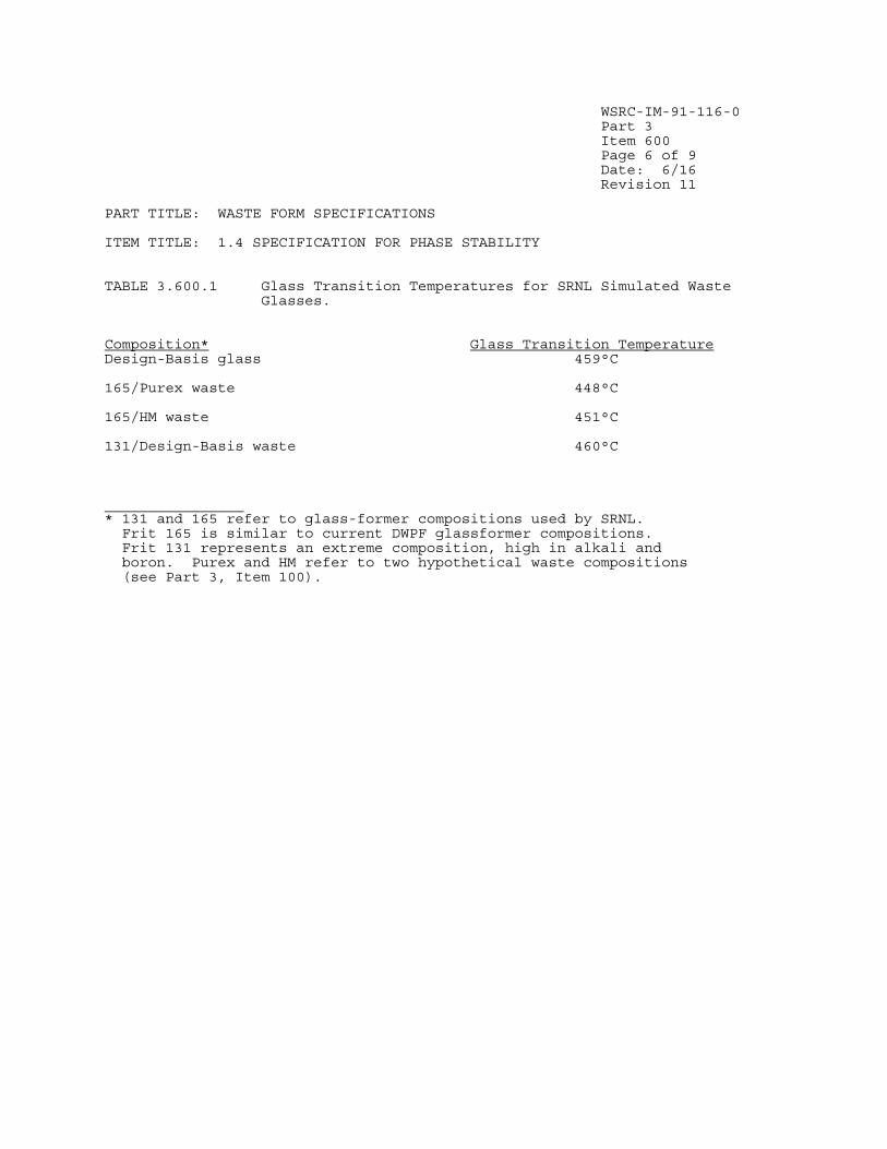
WSRC-IM-91-116-0 Part 3 Item 600 Page 6 of 9 Date: 6/16 Revision 11 PART TITLE: WASTE FORM SPECIFICATIONS ITEM TITLE: 1.4 SPECIFICATION FOR PHASE STABILITY
TABLE 3.600.1 Glass Transition Temperatures for SRNL Simulated Waste Glasses.
Composition* Glass Transition Temperature Design-Basis glass 459°C 165/Purex waste 448°C 165/HM waste 451°C 131/Design-Basis waste 460°C ________________ * 131 and 165 refer to glass-former compositions used by SRNL. Frit 165 is similar to current DWPF glassformer compositions. Frit 131 represents an extreme composition, high in alkali and boron. Purex and HM refer to two hypothetical waste compositions (see Part 3, Item 100).

WSRC-IM-91-116-0 Part 3 Item 600 Page 7 of 9 Date: 6/16 Revision 11 PART TITLE: WASTE FORM SPECIFICATIONS ITEM TITLE: 1.4 SPECIFICATION FOR PHASE STABILITY
TABLE 3.600.2 Temperatures of Free-Standing Canistered Waste Forms. Surface Centerline Surrounding Watts Temp.(°C) Temp.(°C) Air Temp.(°C) 425*,** 34 50 20 510** 54 71 38 690** 58 89 38 1000 66 120 38 ________________ * Expected average value for DWPF canistered waste forms. ** Earlier values used for design purposes.

WSRC-IM-91-116-0 Part 3 Item 600 Page 8 of 9 Date: 6/16 Revision 11 PART TITLE: WASTE FORM SPECIFICATIONS ITEM TITLE: 1.4 SPECIFICATION FOR PHASE STABILITY
FIGURE 3.600.1 Tasks planned to satisfy Specification 1.4, Specification for Phase Stability.
Project glass compositions
(see Part 3, Item 100). [SRNL]
Measure transition temperatures of
projected glasses. [SRNL]
DWPF Hot Startup
Develop TTT diagrams for projected
glasses. [SRNL]
Document design of storage facility
meets specification. [DWPF]
Test glass samples from TTT
diagrams using PCT. [SRNL]
Certify temperature has been below 400°C during
storage. [DWPF]


WSRC-IM-91-116-0
Part 3
Item 700
Page 1 of 4
Date: 9/99
Revision 6
PART TITLE: WASTE FORM SPECIFICATIONS
ITEM TITLE: 1.5 HAZARDOUS WASTE SPECIFICATION
1.5 HAZARDOUS WASTE SPECIFICATION The Producer shall determine and report to DOE/RW the presence or absence of any hazardous waste listed in 40CFR261.31 through 40CFR261.33 , in the waste or in any feed stream proposed for storage and disposal. Any RCRA-listed component in the waste shall require the Producer to petition EPA and receive exemption to delist the waste.
The Producer shall perform the appropriate tests and procedures, described in 40CFR261.20 through 40CFR261.24 , using samples from production runs or prototypical to determine if the waste that will be received by DOE/RW, for transportation and disposal, has hazardous characteristics. Any waste that is shown to have hazardous characteristics shall be treated to remove such characteristics. The Producer shall report and certify in the WQR that the waste is not hazardous, including the absence of any listed components. The characteristic testing methods to be used shall be described in the WCP and the results documented in the WQR. Any modification to these methods needs prior approval from DOE/RW.
Compliance Strategy
The DWPF glass waste form is not hazardous listed waste based on a review that
was conducted to determine if listed hazardous wastes have been discarded in
the high-level waste tanks. To demonstrate that the glass waste form is not
characteristic hazardous waste, the DWPF will perform the Toxic Characteristic
Leaching Procedure (TCLP) on the set of projected glass compositions
described in Part 3, Item 100 and on the Environmental Assessment (EA) glass,
each doped with hazardous metals. This set of projected glasses should bound
the performance of any glass produced in the DWPF while the EA glass
represents an extreme composition.
Implementation
The tasks planned to satisfy this specification are outlined in Figure
3.700.1. They are:
• Projection of glass compositions. This task is described in Part 3, Item
100.
• Documentation that the DWPF waste form is not hazardous listed waste.
• Demonstration that the DWPF waste form is not characteristic hazardous
waste by performing the Toxicity Characteristic Leaching Procedure (TCLP).
Code of Federal Regulations, Protection of Environment, 40 Parts 260 to 299,
40CFR261.31 through 40CFR261.33.
Code of Federal Regulations, Protection of Environment, 40 Parts 260 to 299,
40CFR261.20 through 40CFR261.24.

WSRC-IM-91-116-0
Part 3
Item 700
Page 2 of 4
Date: 9/99
Revision 6
PART TITLE: WASTE FORM SPECIFICATIONS
ITEM TITLE: 1.5 HAZARDOUS WASTE SPECIFICATION
DWPF Waste Stream
The high level waste tanks at SRS primarily contain wastes from reprocessing
irradiated nuclear fuels. These tanks also contain small quantities of waste
generated by two laboratories. A review of practices and procedures for waste
disposal to the high-level waste tanks has been conducted. Each category of
listed waste was considered; hazardous waste from non-specific sources,
hazardous wastes from specific sources, and discarded commercial chemical
products, off-specification species, container residues, and other spill
residues of these commercial chemical products. The review concluded that the
SRS high-level waste tanks do not contain listed wastes. Thus, the DWPF glass
waste form is not hazardous listed waste. This review will be provided in WQR
Volume 13.
Toxicity Characteristic Leaching Procedure
The Toxicity Characteristic Leaching Procedure (TCLP) is an EPA-mandated test
for determining whether a waste form retards the release of hazardous metals
(i.e. arsenic, barium, cadmium, lead, mercury, nickel, selenium, and silver)
from a waste form. In order to demonstrate that the DWPF product is not
characteristic hazardous waste, samples of the projected glass compositions
described in Part 3, Item 100, along with samples of the Environmental
Assessment glass , will be doped with two different levels of hazardous metals
of interest (e.g. silver, barium, lead, cadmium, chromium, and selenium).
Samples of the projected compositions must be doped with hazardous metals
since they were not included during the fabrication of the simulated waste
glasses. Arsenic and mercury will not be considered since arsenic is not
found in SRS waste streams and mercury is removed during chemical processing.
Any residual mercury remaining in the melter feed will be volatilized into the
melter offgas system during melting. The dopant levels will simulate the
amount of metal expected to be found in the actual waste as well as an extreme
case of approximately 3 times the expected level. The glass will be melted
and quenched in order to provide a sample for TCLP. The TCLP will be
performed by a certified laboratory. The TCLP results must be less than the
RCRA limits for leaching of hazardous metals as listed in 40CFR261.24(b) Table
1 in order to verify that DWPF waste glass is not a characteristic hazardous
waste. The organic materials listed in this table will not be considered
since organic materials will not survive the vitrification process (see Part
5, Item 250).
SRTC will ensure that the levels of hazardous metals in the actual waste do
not exceed those levels tested. This will be accomplished during the
qualification of waste portion of the Glass Product Control Program described
in Volume 6 of the Waste Form Qualification Report.
Documentation
Volume 13 of the Waste Form Qualification Report (WQR) will provide the
documentation to show that the SRS high-level waste tanks do not contain
listed waste and thus the DWPF waste form is not hazardous listed waste. The
WQR will also include the results of the TCLP testing of the doped simulated
samples.

WSRC-IM-91-116-0
Part 3
Item 700
Page 3 of 4
Date: 9/99
Revision 6
PART TITLE: WASTE FORM SPECIFICATIONS
ITEM TITLE: 1.5 HAZARDOUS WASTE SPECIFICATION
References
1. Federal Register Rules and Regulations, “Toxicity Characteristic Leaching
Procedure,” Appendix 1, Part 268, Vol. 51, No. 216, November 11, 1986.
2. U.S. Department of Energy, Environmental Assessment Waste Form Selection for SRP High-Level Waste, USDOE Report DOE-EA-0179, July 1982.

WSRC-IM-91-116-0
Part 3
Item 700
Page 4 of 4
Date: 9/99
Revision 6
PART TITLE: WASTE FORM SPECIFICATIONS
ITEM TITLE: 1.5 HAZARDOUS WASTE SPECIFICATION
FIGURE 3.700.1 Tasks planned to satisfy Specification 1.5, Hazardous Waste
Specification.
Project glass
compositions
(see Part 3, Item 100).
[SRTC]
Document DWPF
waste form does not
contain hazardous
listed waste. [DWPF]
Test doped samples
using TCLP. [SRTC]
DWPF
Hot Startup

WSRC-IM-91-116-0
Part 3
Item 800
Page 1 of 3
Date: 9/18
Revision 12
PART TITLE: WASTE FORM SPECIFICATIONS
ITEM TITLE: 1.6 IAEA SAFEGUARDS REPORTING FOR HLW SPECIFICATION
The Producer shall report the following in the Production Records:
(1) The total and fissile uranium and plutonium content of each canister in
grams.
(2) The concentration of plutonium in grams per cubic meter for each
canister.
(3) The ratio by weight of the total element of the following isotopes: U-
233, U-234, U-235, U-236, U-238, Pu-238, Pu-239, Pu-240, Pu-241, and Pu-242.
Compliance Strategy
The strategy for determining the uranium and plutonium isotopes of DWPF glass
is similar to that for the radionuclide inventory during production (Part 3,
Item 400). It uses the same approach of reporting the required information on
a macrobatch basis. The only difference in the strategy is the units used to
report the concentrations. The DWPF will determine the average concentrations
of the uranium and plutonium isotopes by a feed-to-glass correlation (see Part
3, Item 400).
Implementation
The tasks planned to satisfy this specification are outlined in Figure 3.800.1
and are the same as those used to satisfy specification 1.2.2 (see Part 3,
Item 400). These are:
• Development of methods to calculate the concentration of radionuclides by
feed-to-glass correlation.
• Estimation of the errors in the reported radionuclide inventory.
Determining Concentration of Plutonium and Uranium Isotopes
Most of the uranium and plutonium isotopes are present in the SRS waste in
small quantities. Thus, these isotopes cannot be measured in the DWPF
analytical laboratory. The measurements of these isotopes will be based on
analyses of Tank Farm Samples in the same manner described in Part 3, Item
400. Some of the minor isotopes are not reportable based on specification
1.2.2. However, the same methods as described in Part 3, Item 400 will be
used for these minor isotopes.
In order to report the isotopes with the required units, the following
approach will be used. A detailed description of the calculations will be
presented in Volume 4 of the Waste Form Qualification Report.
• Total Uranium and Plutonium Contents. The total uranium and plutonium
contents, determined from the analyses of Tank Farm samples, will be averaged

WSRC-IM-91-116-0
Part 3
Item 800
Page 2 of 3
Date: 9/18
Revision 12
PART TITLE: WASTE FORM SPECIFICATIONS
ITEM TITLE: 1.6 IAEA SAFEGUARDS REPORTING FOR HLW SPECIFICATION
to obtain an average wt% value for the macrobatch. The wt% value will be
multiplied by an average glass weight per canister to obtain the total uranium
and plutonium contents per canister. The total plutonium content will be
divided by an average glass volume to obtain the plutonium content per
canister in grams/m3.
• Ratio by weight of uranium and plutonium isotopes. The individual uranium
and plutonium isotopes will be determined from the DWPF measurements or
analyses of Tank Farm samples. These values will be divided by the total
uranium or plutonium content described above to obtain the ratio by weight.
Estimates of Error
The sources of error for the IAEA reporting requirements are the same as those
described in Part 3, Item 400 for reporting radionuclide inventory. Each of
these sources of error will be characterized and the results reported in
Volume 4 of the Waste Form Qualification Report.
Glass Sampling
At least one glass pour stream sample will be taken by DWPF during the
processing of each sludge batch, analyzed as necessary and archived at the
SRNL Shielded Cells Facility. These samples may be characterized should
additional testing requirements be identified in the future but are no longer
required for batch sampling confirmation.
Documentation
Volume 4 of the Waste Form Qualification Report will include a report on the
methods to be used to determine the uranium and plutonium isotopes during
production. The precision and accuracy of the methods used, based upon
demonstrations in the SRNL Shielded Cells Facility, and analyses of samples
from the Tank Farm, will also be reported. The Waste Form Qualification
Report will also contain estimates of the errors of calculational algorithms
used.
The Production Record for each canistered waste form will include the
following:
• Total uranium and plutonium content per canister in grams
• Mass ratios of the required uranium and plutonium isotopes
• Total plutonium content per canister expressed as grams/m3
This information will be reported as a single value for each canister in the
entire macrobatch.

WSRC-IM-91-116-0
Part 3
Item 800
Page 3 of 3
Date: 9/18
Revision 12
PART TITLE: WASTE FORM SPECIFICATIONS
ITEM TITLE: 1.6 IAEA SAFEGUARDS REPORTING FOR HLW SPECIFICATION
FIGURE 3.800.1 Tasks planned to satisfy Specification 1.6, IAEA Safeguards
Reporting for HLW Specification.
DWPF
Hot
Startup
Supplement radionuclide
inventory strategy (see
Part 3, Item 400)
[DWPF]
Estimate errors in
reported isotopes
[SRNL]
Report U and Pu
isotopes during actual
DWPF operations
[DWPF]
Confirm reported
radionuclide inventory
using glass samples*
[SRNL]
*Beginning with Sludge Batch 9, glass samples will be archived at SRNL and
only characterized upon request.

WSRC-IM-91-116-0
Part 4
Item 100
Page 1 of 7
Date: 6/16
Revision 11
PART TITLE: CANISTER SPECIFICATIONS
ITEM TITLE: 2.1 MATERIAL SPECIFICATION
2.1 MATERIAL SPECIFICATION The waste form canister, the canister label, and any secondary canister applied by the producer shall be fabricated from austenitic stainless steel. Applicable ASTM or other nationally recognized alloy specifications and the compositions of the canister materials, the canister label materials, any secondary canister material, and any filler materials used in welding shall be
included in the WCP. Documentation of compliance shall be included in the Production Records.
Compliance Strategy
The DWPF will ensure that the materials in the procured canister assembly meet
the specification through a combination of component specifications, and
inspections to ensure that these component specifications are met.
Procurement documents for the DWPF canisters, including canister labels,
require that all material used in fabrication of the canisters shall meet the
compositional requirements of the appropriate ASTM or ASME designations (or
equivalent). All of these materials are austenitic stainless steel in nature.
The procurement documents also require that material certifications be
provided to DWPF for the metal heat used for fabrication of each component.
The canisters are to be inspected by a Supplier Surveillance Representative
(SSR) prior to shipment to DWPF. This inspection includes verification of
documentation on the compositions of canister materials.
At the present time, the DWPF has reserved space in the welding cell for
equipment to package a faulty glass-filled canister in a secondary canister.
Equipment and process development have been suspended because of the very
unlikely nature of the need for such equipment. If, at a later date, it is
determined that a secondary canister is needed, equipment and process
development will be re-initiated. Information on the secondary canister would
then be supplied in a revision to the WQR. The material composition would be
reported in the WCP. Any secondary canister would require use of the same
materials specified above.
Implementation
The tasks planned to satisfy this specification are outlined in
Figure 4.100.1. These are:
• Specification of only austenitic stainless steel materials in the canister
procurement documents.
• Delivery to the DWPF of documented certification that these material
specifications have been met, by the vendor.
• Verification that only austenitic materials have been used.
Annual Book of ASTM Standards, American Society of Testing and Materials,
Easton, MD (1987)

WSRC-IM-91-116-0
Part 4
Item 100
Page 2 of 7
Date: 6/16
Revision 11
PART TITLE: CANISTER SPECIFICATIONS
ITEM TITLE: 2.1 MATERIAL SPECIFICATION
Specification of Canister Materials
The current procurement specifications for the canisters require that the
various parts of the canister assembly be fabricated from the following
materials.
Cylinder ASTM A240 Type 304L stainless steel
Nozzle and Flange ASTM A965 Type F304L stainless steel (formerly A336)
Tapered Plug ASTM A240 Type 304L stainless steel
Neck Sleeve ASTM A479 Type S21800 stainless steel (Nitronic 60)
Heads ASTM A240 Type 304L stainless steel
Weld Plug ASTM A240 Type 304L stainless steel
Repair Plug ASTM A479 Type S21800 stainless steel (Nitronic 60)
Repair Cap ASTM A240 Type 304L stainless steel
Weld Filler Metal ANSI/AWS A5.9 ER308L or ASME SFA5.9
(also used for label) ER308L stainless steel
The alloy compositions corresponding to these specifications are given in
Tables 4.100.1 to 4.100.4. Canisters used in non-radioactive equipment
development and testing at SRTC have been procured to these specifications.
Documented Certification and Verification
The canister procurement specifications require that the vendor of the
canister assembly supply material certifications to DWPF for each heat of
metal used. An SRS representative at the vendor's location will perform
verification activities to ensure that only specified materials were used.
These activities will be described in Volume 8 of the Waste Form Qualification
Report.
Documentation
The WAPS require that the DWPF certify that the canisters are fabricated from
the materials identified in the Waste Form Compliance Plan. The Waste Form
Qualification Report will reference the canister procurement specifications,
and will describe the verification activities which will be performed. The
Production Records will reference the procurement documents for each canister.
The detailed procurement documents will include the actual specifications,
purchase orders, vendor and heat identification records, certificates of
analyses, and inspection records. If these values are outside the specified
ranges, the canister will be identified as a nonconforming item. Its
disposition will be in accordance with the procedure outlined in Part 6, Item
300.

WSRC-IM-91-116-0
Part 4
Item 100
Page 3 of 7
Date: 6/16
Revision 11
PART TITLE: CANISTER SPECIFICATIONS
ITEM TITLE: 2.1 MATERIAL SPECIFICATION
TABLE 4.100.1 Required chemical composition of ASTM A240 Type 304L stainless
steel.
Component Amount (wt%)
Carbon 0.030 maximum
Manganese 2.00 maximum
Phosphorus 0.045 maximum
Sulfur 0.030 maximum
Silicon 0.75 maximum
Chromium 18.00 - 20.00
Nickel 8.00 - 12.00
Other elements Nitrogen - 0.10 maximum
Reference: Annual Book of ASTM Standards, 1.03, American Society for
Testing and Materials, Easton, MD, 62 (1990).
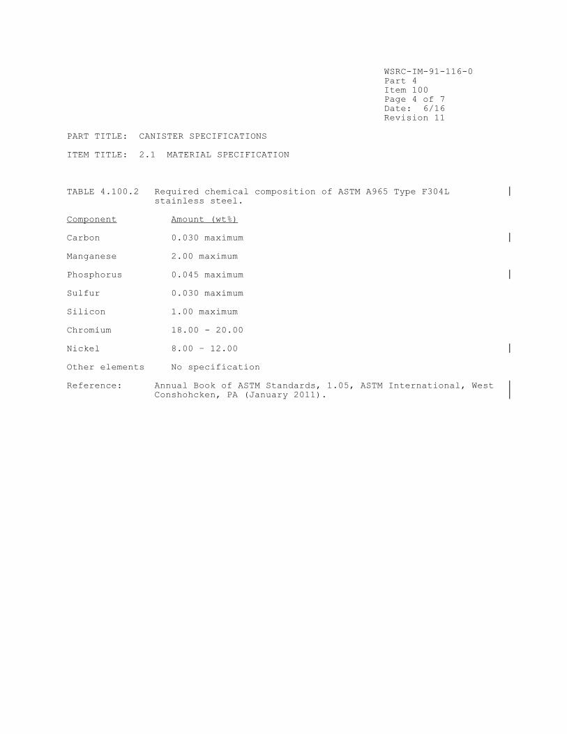
WSRC-IM-91-116-0
Part 4
Item 100
Page 4 of 7
Date: 6/16
Revision 11
PART TITLE: CANISTER SPECIFICATIONS
ITEM TITLE: 2.1 MATERIAL SPECIFICATION
TABLE 4.100.2 Required chemical composition of ASTM A965 Type F304L
stainless steel.
Component Amount (wt%)
Carbon 0.030 maximum
Manganese 2.00 maximum
Phosphorus 0.045 maximum
Sulfur 0.030 maximum
Silicon 1.00 maximum
Chromium 18.00 - 20.00
Nickel 8.00 – 12.00
Other elements No specification
Reference: Annual Book of ASTM Standards, 1.05, ASTM International, West
Conshohcken, PA (January 2011).

WSRC-IM-91-116-0
Part 4
Item 100
Page 5 of 7
Date: 6/16
Revision 11
PART TITLE: CANISTER SPECIFICATIONS
ITEM TITLE: 2.1 MATERIAL SPECIFICATION
TABLE 4.100.3 Required chemical composition of ASTM A479 Type S21800
stainless steel (Nitronic 60).
Component Amount (wt%)
Carbon 0.10 maximum
Manganese 7.00 - 9.00
Phosphorus 0.060 maximum
Sulfur 0.030 maximum
Silicon 3.50 - 4.50
Chromium 16.00 - 18.00
Nickel 8.00 - 9.00
Other elements Nitrogen 0.08 - 0.18
Reference: Annual Book of ASTM Standards, 1.05, American Society for
Testing and Materials, Easton, MD, 361 (1990).

WSRC-IM-91-116-0
Part 4
Item 100
Page 6 of 7
Date: 6/16
Revision 11
PART TITLE: CANISTER SPECIFICATIONS
ITEM TITLE: 2.1 MATERIAL SPECIFICATION
TABLE 4.100.4 Required Chemical Composition of ASME SFA5.9
ER308L and ANSI/AWS A5.9 ER308L Stainless Steel.
Amount (wt%)*
Component ANSI/AWS A5.9 ASME SFA5.90
Carbon 0.03 maximum 0.03 maximum
Manganese 1.0 - 2.5 1.0 - 2.5
Phosphorus 0.03 maximum 0.03 maximum
Sulfur 0.03 maximum 0.03 maximum
Silicon 0.30 - 0.65 0.30 - 0.65
Chromium 19.5 - 22.0 19.5 - 22.0
Nickel 9.0 - 11.0 9.0 - 11.0
Molybdenum 0.75 maximum 0.75 maximum
Copper 0.75 maximum 0.75 maximum
Other elements No specification
* Additional constraint on weld filler material composition (per
procurement specification):
1.40 < (Cr)eq/(Ni)eq < 1.67
where (Cr)eq = %Cr + 1.5% Si + %Mo + 0.5% Nb
and (Ni)eq = %Ni + 0.5%Mn + 30%C + 30%N
References: 1. American National Standards Institute/American Welding Standard, Section A5.9.
2. ASME Boiler and Pressure Vessel Code, Section II, Part C, American Society of Mechanical Engineers, United Engineering
Center, 345 East 47th St., New York, NY 10017, (1989).

WSRC-IM-91-116-0
Part 4
Item 100
Page 7 of 7
Date: 6/16
Revision 11
PART TITLE: CANISTER SPECIFICATIONS
ITEM TITLE: 2.1 MATERIAL SPECIFICATION
FIGURE 4.100.1 Tasks planned to satisfy Specification 2.1, Material
Specification.
Specify materials in
canister procurement
documents. [DWPF]
DWPF
Hot Startup
Vendor provides
material certifications to
DWPF for each heat.
[DWPF]
Authenticate
certifications that vendor
used austenitic stainless
steel.[DWPF]


WSRC-IM-91-116-0
Part 4
Item 200
Page 4 of 6
Date: 6/03
Revision 7
PART TITLE: CANISTER SPECIFICATIONS
ITEM TITLE: 2.2 FABRICATION AND CLOSURE SPECIFICATION
Documentation
Volume 8 of the Waste Form Qualification Report will reference the canister
procurement specifications. Volume 8 will also include a report on the
parametric testing of weld conditions and associated leak rates, and
validation of the parametric testing during the Startup Test Program.
The Production Record (Appendix 1.200.1) for each canistered waste form will
certify that the canister components and the entire canister assembly were
fabricated according to approved drawings and procedures, and meet the
procurement specifications.
The Production Record will also certify the integrity of the final closure
weld made in the DWPF. The Production Records will report the force, current,
and duration of application of the current as recorded by the computer
collecting the data from the DWPF welder. If these values are outside the
range of parameters which have been shown to produce a leaktight weld, the
canister weld will be identified as a nonconforming item. Its disposition
will be in accordance with the procedure outlined in Part 6, Item 300.
References
1. ASME Boiler and Pressure Vessel Code, Section IX, Part QW, American Society of Mechanical Engineers, United Engineering Center, 345 East 47th St.,
New York, NY 10017, (1989).
2. ASME Boiler and Pressure Vessel Code, Section V, American Society of Mechanical Engineers, United Engineering Center, 345 East 47th St., New York,
NY 10017, (1989).
3. ASME Boiler and Pressure Vessel Code, Section VIII, American Society of Mechanical Engineers, United Engineering Center, 345 East 47th St., New York,
NY 10017, (1989).
4. R. E. Erickson to R. Schepens memorandum, “Defense Waste Processing
Facility Canister Specification Changes,” (1998).
5. B. J. Eberhard, and J. W. Kelker, "High Current Resistance Welding of
Nuclear Waste Canisters," Welding Journal, 61(6), 15-9 (1982).

WSRC-IM-91-116-0
Part 4
Item 200
Page 5 of 6
Date: 6/03
Revision 7
PART TITLE: CANISTER SPECIFICATIONS
ITEM TITLE: 2.2 FABRICATION AND CLOSURE SPECIFICATION
FIGURE 4.200.1 Tasks planned to satisfy Specification 2.2, Fabrication and
Closure Specification.
Verify canister
fabrication methods prior
to shipment. [DWPF]
Specify fabrication
methods in canister
procurement
documents. [DWPF]
Verify weld
leaktightness in
DWPF Startup Test
Program [DWPF]
DWPF
Hot Startup
Document final
closure method for
canisters.
[SRTC]
Parametric study to
determine acceptable
weld conditions.
[DWPF]
Record actual weld
paremeters used.
[DWPF]

WSRC-IM-91-116-0
Part 4
Item 200
Page 6 of 6
Date: 6/03
Revision 7
PART TITLE: CANISTER SPECIFICATIONS
ITEM TITLE: 2.2 FABRICATION AND CLOSURE SPECIFICATION
FIGURE 4.200.2 Components and overall nominal dimensions of the DWPF
canister.
We l d 1
Di s he d bo t t om
He a d
We l d 2
We l d 3
Noz z l e a nd f l a nge
Ove r a l l l e ng t h 118 . 0 i n ( 299 . 72 c m)
Out s i de d i a me t e r 24 . 0 i n ( 60 . 96 c m)
Nomi na l wa l l t h i c kne s s :
Be t we e n We l d 1 a nd 2 0 . 63 i n ( 1 . 59 c m)Be t we e n We l d 2 a nd 3 0 . 37 i n
( 0 . 95 c m)Be l ow We l d 3 0 . 50 i n
( 1 . 27 c m)
Se a mwe l d

WSRC-IM-91-116-0
Part 4
Item 300
Page 1 of 6
Date: 9/99
Revision 6
PART TITLE: CANISTER SPECIFICATIONS
ITEM TITLE: 2.3 IDENTIFICATION AND LABELING SPECIFICATIONS
2.3 IDENTIFICATION AND LABELING SPECIFICATION 2.3.1 Identification The Producer shall assign a unique alphanumeric identifier to label each outermost canister that is produced. This label shall appear on the canistered waste form and on all documentation pertinent to that particular
canistered waste form. 2.3.2 Labeling Each canister shall be labeled in two locations: one visible from the top and one from the side of the canister. The identification code shall be printed in a type size of at least 92 points using a sans serif type face. A proposed layout shall be provided in the WCP. Labels shall be applied to the exterior of the outermost canister and shall not cause the dimensional limits (Specification 3.11) to be exceeded. The label shall be designed to be legible after filling and storage at the Producer’s facility and shipment to the repository. The label shall be an integral part of the canister (e.g. embossed) and shall not impair the integrity of the canister.
Compliance Strategy
The identification code planned for the canistered waste forms is a six digit
alphanumeric code consisting of the letter "S" followed by five numbers. The
label lettering will conform to the specification.
The DWPF canister label is made of welding rod bead-welded directly to the
canister surface. The welding rod is the same austenitic stainless steel
composition used for canister assembly, to assure compatibility with the
canister. This labeling technique has been shown suitable by fabricating
sample labels, frit blasting them in a manner similar to that in the DWPF, and
then establishing that they are still easily visible under process viewing
conditions.
Implementation
The tasks being performed to satisfy this specification are outlined in
Figure 4.300.1. As noted in the Compliance Strategy, the alphanumeric code
for DWPF canisters has been selected. The other actions performed to satisfy
this specification are:
• Development of a labeling method. This includes performing studies of
various labels and labeling methods to choose a reference process, selecting a
lettering shape and style, fabricating test labels, and confirming the
visibility of the labeling scheme even after frit blasting.
• Inclusion of the labeling method in the canister procurement
specifications.

WSRC-IM-91-116-0
Part 4
Item 300
Page 2 of 6
Date: 9/99
Revision 6
PART TITLE: CANISTER SPECIFICATIONS
ITEM TITLE: 2.3 IDENTIFICATION AND LABELING SPECIFICATIONS
• Estimation of the service life of the label.
Development of Labeling Method
The reference labeling technique was chosen based on tests of the visibility
of labels applied by various techniques, both before and after decontamination
of the canister by frit blasting (see Part 5, Item 400). The label made by
the reference technique was best able to maintain its legibility after
decontamination. Tests through an aged shielding window showed that the label
could be viewed remotely up to 10 feet away without magnification, and could
be easily read at least 30 feet away with a 10X magnification lens attached to
a video camera. The label was most visible under indirect light which
produced a profile shadow. Intense direct lighting tended to reduce the
contrast between the label and the canister, making it more difficult to read.
Given proper lighting, viewing angle was found to have little effect on label
legibility.
Labeling Requirements in Canister Procurement Specification
The canister labeling method selected by the DWPF is to bead-weld characters
(using Type 308L welding rod) on the canister surface. The type face is sans
serif style Megaron Medium. Letters are to be 5 cm high and 3.8 cm between
centers. The canister vendor may use any method to provide uniform
characters, subject to prior approval by DWPF. The alphanumeric code for
identifying the DWPF canistered waste forms is a six digit alphanumeric string
consisting of the letter "S" followed by five numbers. A label is placed on
the top head and cylinder of each canister at the locations shown in Figures
4.300.2 and 4.300.3. After completion of labeling, characters are to have a
profile height of about 0.16 cm. The label will be inspected with the rest of
the canister, and any imperfections which could trap contamination will be
removed before acceptance of the canister. This is included in the canister
procurement specifications for the DWPF canister, which will be referenced in
the Volume 8 of the WQR.
Estimation of Service Life
The DWPF will estimate the service life of the DWPF canister labels to provide
assurance that the labels will remain legible throughout the specified period.
The welding rod used as the bead-welded label characters on the canister
surface will be Type 308L austenitic stainless steel. This is the same
material used to assemble the canister (see Part 4, Item 100). The service
life of the label should be comparable to that of the welds which hold the
canister together, because the label will be made from the same material as
the canister fabrication welds and should experience the same thermal
treatment during filling. The service life of the label will be estimated.
It will be shown that for reasonable estimates of the time of shipment, the
service life is not exceeded. Thus, after filling the canister, the DWPF
should not need to take any special precautions to protect the canister label.
During the Startup Test Program, the microstructures of the label and the
canister welds will be characterized, and related to one another.
Since the conditions of storage at the repository are not known the DWPF will
assume that these will be similar to storage conditions at SRS. The DWPF
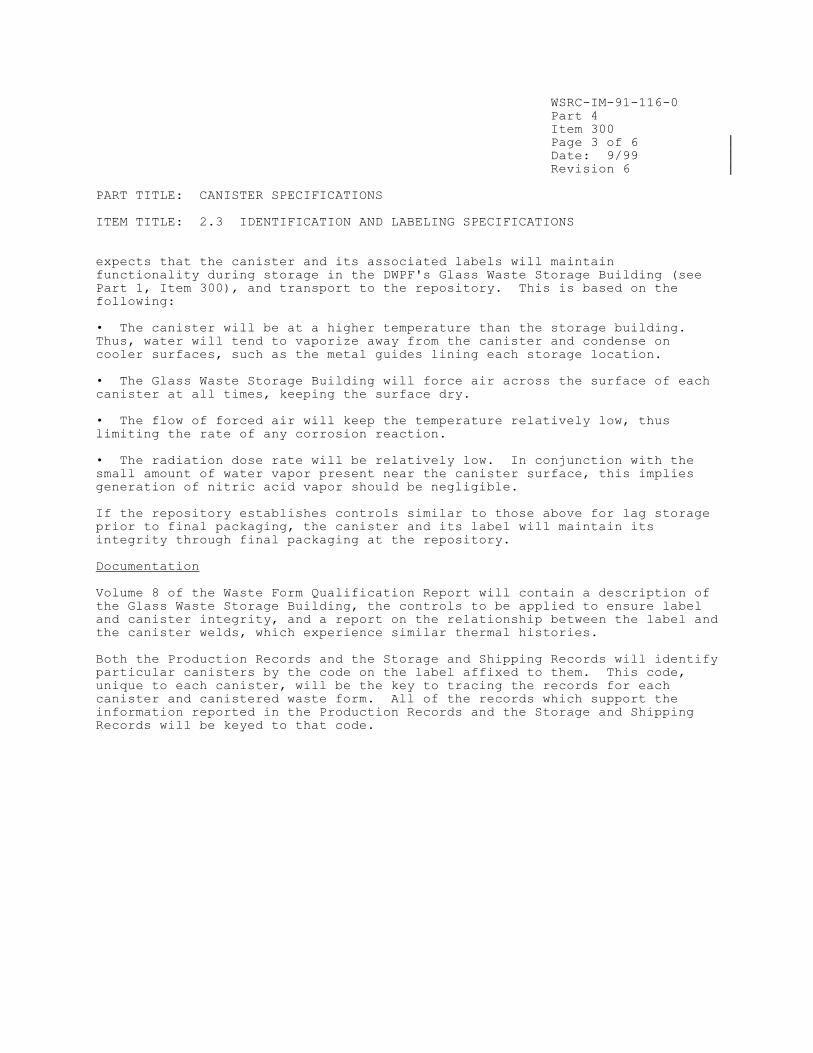
WSRC-IM-91-116-0
Part 4
Item 300
Page 3 of 6
Date: 9/99
Revision 6
PART TITLE: CANISTER SPECIFICATIONS
ITEM TITLE: 2.3 IDENTIFICATION AND LABELING SPECIFICATIONS
expects that the canister and its associated labels will maintain
functionality during storage in the DWPF's Glass Waste Storage Building (see
Part 1, Item 300), and transport to the repository. This is based on the
following:
• The canister will be at a higher temperature than the storage building.
Thus, water will tend to vaporize away from the canister and condense on
cooler surfaces, such as the metal guides lining each storage location.
• The Glass Waste Storage Building will force air across the surface of each
canister at all times, keeping the surface dry.
• The flow of forced air will keep the temperature relatively low, thus
limiting the rate of any corrosion reaction.
• The radiation dose rate will be relatively low. In conjunction with the
small amount of water vapor present near the canister surface, this implies
generation of nitric acid vapor should be negligible.
If the repository establishes controls similar to those above for lag storage
prior to final packaging, the canister and its label will maintain its
integrity through final packaging at the repository.
Documentation
Volume 8 of the Waste Form Qualification Report will contain a description of
the Glass Waste Storage Building, the controls to be applied to ensure label
and canister integrity, and a report on the relationship between the label and
the canister welds, which experience similar thermal histories.
Both the Production Records and the Storage and Shipping Records will identify
particular canisters by the code on the label affixed to them. This code,
unique to each canister, will be the key to tracing the records for each
canister and canistered waste form. All of the records which support the
information reported in the Production Records and the Storage and Shipping
Records will be keyed to that code.
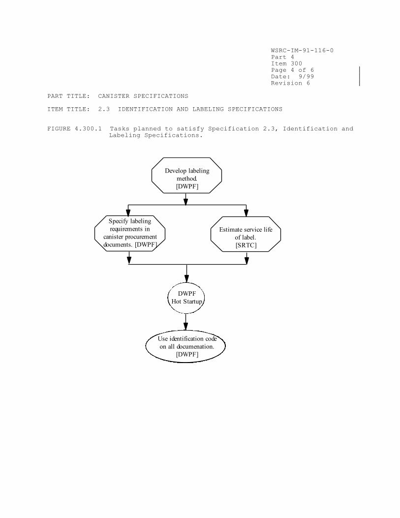
WSRC-IM-91-116-0
Part 4
Item 300
Page 4 of 6
Date: 9/99
Revision 6
PART TITLE: CANISTER SPECIFICATIONS
ITEM TITLE: 2.3 IDENTIFICATION AND LABELING SPECIFICATIONS
FIGURE 4.300.1 Tasks planned to satisfy Specification 2.3, Identification and
Labeling Specifications.
Specify labeling
requirements in
canister procurement
documents. [DWPF]
DWPF
Hot Startup
Estimate service life
of label.
[SRTC]
Develop labeling
method.
[DWPF]
Use identification code
on all documenation.
[DWPF]


WSRC-IM-91-116-0
Part 4
Item 300
Page 6 of 6
Date: 9/99
Revision 6
PART TITLE: CANISTER SPECIFICATIONS
ITEM TITLE: 2.3 IDENTIFICATION AND LABELING SPECIFICATIONS
FIGURE 4.300.3 Placement of side label on DWPF canister (nominal dimensions
shown).
WSRC-IM-91-116-0
Part 4
Item 400
Page 1 of 5
Date: 3/14
Revision 10
PART TITLE: CANISTER SPECIFICATIONS
ITEM TITLE: 2.4 SPECIFICATION FOR CANISTER LENGTH AND DIAMETER
2.4 SPECIFICATION FOR CANISTER LENGTH AND DIAMETER The Producer must describe in the WCP that the strategy for meeting these specifications will meet the requirements of the WA-SRD. 2.4.1 Length Specification
The overall length of the unfilled canister, after accounting for the closure method, shall be 3.000 m (+ 0.005 m, - 0.020 m), including the neck and handling flange. The measured length of the unfilled canister shall be reported in the Production Records. 2.4.2 Diameter Specification The outer diameter of the unfilled canister shall be 61.0 cm (+ 1.5 cm, - 1.0 cm). The measured diameter of the unfilled canister shall be reported in the Production Records.
Compliance Strategy
The DWPF will ensure that the canister dimensions are within the specified
limits by controlling the canister procurement process. This control will be
accomplished through the canister procurement specifications which include
inspections to ensure that the canister is acceptable before it leaves the
vendor’s shop. The length and diameter of the unfilled canisters will be
measured by the canister supplier prior to shipment to the DWPF. Measurements
of non-radioactive canistered waste forms produced under conditions
representing the range of those expected in the DWPF show that the
vitrification process does not significantly affect the dimensions of the
canistered waste form. Thus, the filled DWPF canisters (canistered waste
forms) will also meet the dimensional requirements and the DWPF’s strategy for
controlling dimensions is acceptable. The weld plug will extend approximately
0.002 m above the nominal 3 m of canister length.
Implementation
The tasks planned to satisfy this specification are outlined in Figure
4.400.1. These are:
• Development of requirements for the canister length and diameter, which
have been included in the canister procurement specifications. This also
includes identification of canister inspection requirements to ensure that the
specifications are met at the vendor's shop.
• Determination of the change in canister dimensions during glass pouring at
the pilot plant facilities.
• Determination of the additional length due to the weld plug.

WSRC-IM-91-116-0
Part 4
Item 400
Page 2 of 5
Date: 3/14
Revision 10
PART TITLE: CANISTER SPECIFICATIONS
ITEM TITLE: 2.4 SPECIFICATION FOR CANISTER LENGTH AND DIAMETER
Canister Procurement Specifications
The DWPF has developed detailed canister procurement specifications which
specify the length and diameter of canisters. In addition, inspection
requirements are being defined, to ensure that the purchased canisters
actually meet specifications before they leave the vendor's shop.
Change in Dimension During Pouring
Seven prototypical DWPF canisters were carefully measured and then filled with
glass at the SRS pilot plant facility under both design basis (continuous
filling) and the most likely upset (pouring rapidly in short bursts)
conditions. The data for these tests can be found in Volume 8 of the Waste
Form Qualification Report. Seven canisters were used so that estimates of
uncertainties for each condition could be developed (however, the two data
sets proved to be indistinguishable in terms of this specification).
These canisters were then re-measured to determine the effects of canister
filling on canister dimensions. Figure 4.400.2 contains a canister diagram
indicating measurement locations, and the means and standard deviations of the
measured dimensions. The diameter of the canisters was measured at five
different elevations: top end, top, middle, bottom, bottom end. The reported
diameter value, 24.00 ± 0.12 inches (60.96 ± 0.30 cm), was calculated using
measurements from all of the canisters at all elevations. The diameter is
well within the specification even after filling (maximum deformation: 0.161
inches (0.409 cm). Based on the small process-induced dimensional changes, it
appears that compliance with the dimensional specifications can best be
established through strict adherence to the canister procurement
specifications. Volume 8 of the WQR will provide the technical basis for this
conclusion, and the details of the measurements and calculations. The
conclusions drawn from canisters filled at the SRS pilot facility will be
confirmed during the DWPF Startup Test Program and these results also reported
in Volume 8.
Canister Weld Plug Height
The final weld plug increases the overall length of the canistered waste form
slightly. This is due to the fact that the weld plug protrudes above the top
of the nozzle flange after upset resistance welding (see Part 4, Item 200).
For the seven prototypically filled canisters used in the drop tests (see Part
5, Item 700), the values for this protrusion ranged from 0.032 to 0.038 inches
(less than 0.001 m). The canister procurement specification limit on canister
length is tighter than the WAPS requirement and thus this small increase in
length due to the weld plug will not affect the DWPF’s ability to comply with
the WAPS. The increase in canister length due to the weld plug will be
further evaluated during the weld parametric study (see Part 4, Item 200).

WSRC-IM-91-116-0
Part 4
Item 400
Page 3 of 5
Date: 3/14
Revision 10
PART TITLE: CANISTER SPECIFICATIONS
ITEM TITLE: 2.4 SPECIFICATION FOR CANISTER LENGTH AND DIAMETER
Documentation
Volume 8 of the Waste Form Qualification Report (WQR) will reference the
canister procurement specifications, and inspection procedures. The WQR will
also include a report on the effect of the vitrification process on the
canistered waste form dimensions, including the additional length due to the
weld plug.
The Production Record for each canistered waste form shall contain the as-
purchased diameter and length of the canister. If these values are outside
the range for canister diameter and length, the canister will be identified as
a nonconforming item. Its disposition will be in accordance with the
procedure outlined in Part 6, Item 300.

WSRC-IM-91-116-0
Part 4
Item 400
Page 4 of 5
Date: 3/14
Revision 10
PART TITLE: CANISTER SPECIFICATIONS
ITEM TITLE: 2.4 SPECIFICATION FOR CANISTER LENGTH AND DIAMETER
FIGURE 4.400.1 Tasks planned to satisfy Specification 2.4, Specification for
Canister Length and Diameter.
Specify length and
diameter in canister
procurement
documents. [DWPF]
DWPF
Hot Startup
Determine additional
length due to weld
plug or repair cap
weld. [DWPF]
Determine change in
dimensions during
pouring. [SRTC]
Report length and
diameter.
[DWPF]

WSRC-IM-91-116-0
Part 4
Item 400
Page 5 of 5
Date: 3/14
Revision 10
PART TITLE: CANISTER SPECIFICATIONS
ITEM TITLE: 2.4 SPECIFICATION FOR CANISTER LENGTH AND DIAMETER
FIGURE 4.400.2 Components and dimensions of the seven DWPF canisters filled
under design-basis and possible upset conditions in pilot
plant tests (calculated for all canisters)*.

WSRC-IM-91-116-0
Part 5
Item 100
Page 1 of 7
Date: 9/99
Revision 6
PART TITLE: CANISTERED WASTE FORM SPECIFICATIONS
ITEM TITLE: 3.1 FREE LIQUID SPECIFICATION
3.1 FREE LIQUID SPECIFICATION The Producer shall ensure that the canistered waste form does not contain detectable amounts of free liquids. The Producer shall describe the method of compliance in the WCP and provide documentation of the ability to comply, and of the detection limits, in the WQR.
Compliance Strategy
The vitrification process, operating at 1150°C, with a nominal melter
residence time of 65 hours, will evaporate all free liquids from the waste
feed stream as the waste is converted into molten glass. The glass pouring
into the canister will be at a temperature of about 1000°C, and the canister
under a slight vacuum. Thus, free liquids will not enter the canister with
the molten glass stream, and any liquids present in the canister prior to
pouring are unlikely to remain due to the heat of the molten glass and the
reduced pressure.
The most likely source of free liquids in the canister is the water/frit
slurry used to decontaminate the canister. A shrink-fit seal has been
developed to ensure that this slurry does not enter the canister. This
temporary seal called the Inner Canister Closure (ICC) will be inserted into
the canister neck after filling, and before canister decontamination, to
prevent inleakage of the decontamination slurry. Every ICC will be tested to
ensure it is watertight. Administrative controls will be used to prevent the
introduction of any free liquids into the canisters before or after glass
filling. Tests will be performed in the facility to demonstrate the
effectiveness of the controls.
Implementation
The tasks planned to satisfy this specification are outlined in Figure
5.100.1. They are
Identification of the sources of liquids in the canistered waste form.
Demonstration that borosilicate glass does not contain free liquids, and
that they cannot enter the canister with the molten glass stream.
Development of controls to prevent the introduction of free liquids into
the canister, either before or after filling.
Development of a leaktight temporary seal to be used during canister
decontamination.
Demonstration of the effectiveness of the controls as part of the Startup
Test Program.

WSRC-IM-91-116-0
Part 5
Item 100
Page 2 of 7
Date: 9/99
Revision 6
PART TITLE: CANISTERED WASTE FORM SPECIFICATIONS
ITEM TITLE: 3.1 FREE LIQUID SPECIFICATION
Identification of the Sources of Liquids
SRTC will conduct a review of the entire process to identify all of the
possible sources of free liquids and other foreign materials in the canistered
waste form. This review will begin at the canister vendor’s shop and proceed
through application of the final closure weld at the DWPF. These results will
be documented in Volume 9 of the Waste Form Qualification Report (WQR).
It is assumed that water vapor will be present inside the canistered waste
form from the ambient cell air. Worst case dew point calculations, based on a
185°C sealing temperature and the most humid credible atmospheric conditions
(which produce a dew point temperature of 35°C due to waste heat loading),
indicate a maximum of 4.6 grams of water vapor will be trapped in the vapor
space within DWPF canistered waste forms. The somewhat elevated steady-state
temperatures expected during interim storage at the DWPF will prevent this
water vapor from condensing.
Absence of Free Liquids in DWPF Glass
As noted in the Compliance Strategy, the high temperatures of the DWPF
vitrification process make it very unlikely that process liquids will survive
to enter the canister with the pouring glass stream. In addition,
borosilicate waste glass itself contains no free liquids. The WQR will
document that borosilicate waste glass will contain no detectable free
liquids, and that free liquids cannot enter the canister with the molten waste
glass.
Development of Controls to Prevent Ingress of Free Liquids
Based on the identification of the sources of free liquids, the DWPF will
establish controls to prevent the introduction of free liquids into the
canister, both before and after filling. These will be primarily procedural
(e.g., inspections) but will also include the temporary seal (described below)
and final closure weld (described in Part 4, Item 200). These controls will
be described in the WQR.
Development of Temporary Seal Process
After filling with glass, the canister is decontaminated by blasting a slurry
of glass frit at the canister surface. This is the most likely method of
ingress of free liquids. The DWPF has developed a watertight temporary seal
to prevent water (or other liquids) from entering the canister after filling
before the final closure weld is made. A shrink-fit seal technique was
selected because it uses the heat from the glass filling operation to make the
seal. It is a simple, reliable process because it requires no additional
equipment in the hot cell.
The temporary shrink-fit seal, called the Inner Canister Closure (ICC), is
made at the top of the canister nozzle after the canister has been filled with
glass and vented to the off-gas system for to remove volatile species. Figure
5.100.2 outlines this process. The seal is made by placing the cold seal plug
in the hot canister sleeve (emplaced in canister during fabrication – see Part

WSRC-IM-91-116-0
Part 5
Item 100
Page 5 of 7
Date: 9/99
Revision 6
PART TITLE: CANISTERED WASTE FORM SPECIFICATIONS
ITEM TITLE: 3.1 FREE LIQUID SPECIFICATION
FIGURE 5.100.1 Tasks planned to satisfy Specification 3.1, Free Liquid
Specification.
Identify sources of free
liquids in the DWPF
waste form.
[SRTC]
Demonstrate waste
glass does not contain
free liquids.
[DWPF]
Develop leaktight
temporary seal to be used
during decontamination.
[SRTC]
Develop controls to
keep liquids out of
canister.
[DWPF]
Demonstrate
effectiveness of
controls during Startup
Test Program. [DWPF]
DWPF
Hot
Startup
Record leak rate of
temporary seal.
[DWPF]


WSRC-IM-91-116-0
Part 5
Item 150
Page 1 of 4
Date: 9/99
Revision 6
PART TITLE: CANISTERED WASTE FORM SPECIFICATIONS
ITEM TITLE: 3.2 GAS SPECIFICATION
3.2 GAS SPECIFICATION The Producer shall ensure that the canistered waste form does not contain detectable amounts of free gas other than air, the residuals of air, inert cover, and radiogenic gases. The internal gas pressure immediately after closure shall not exceed 150 kPa (22 psia) at 25°C. The Producer shall describe the method of compliance in the WCP and provide documentation of the
ability to comply with this specification, and of the detection limits, in the WQR. The Producer shall also document in the WQR the quantities and compositions of any gases that might accumulate inside the canister from radiogenic decay in the event that the canistered waste form temperature exceeds 400°C. If a canistered waste form exceeds 400°C, it is nonconforming and shall be resolved in accordance with Section 4.0. Data/information reporting in the WQR, during the qualification process, shall be limited to temperatures up to 500°C.
Compliance Strategy
The DWPF will exclude free gases (other than air, the residuals of air, inert
cover and radiogenic gases) from the canistered waste form through a
combination of physical and administrative control measures. Administrative
controls will be used to prevent the introduction of any gases into the
canisters after filling and sealing. Physical barriers will be used to
prevent the ingress of extraneous (non-radiogenic) gases. The amounts of
gases generated due to radioactive decay will be calculated.
Implementation
The tasks planned to satisfy this specification are outlined in
Figure 5.150.1. These are:
• Identification of the sources of free gas.
• Demonstration that borosilicate glass does not contain free gas, and that
it cannot enter the canister with the molten glass stream.
• Demonstration that exposure of the glass to 500°C will not release free
gas. The limit of 500°C is conservative since the limit for canister exposure
after cooldown is 400°C (see Part 3, Item 600).
• Calculation of the amount of gas generated radiogenically.
• Development and demonstration of controls to ensure that free gases are not
introduced into the canister.
During processing, there is no process step which can pressurize the DWPF
canistered waste form. Thus, the ability to meet the internal pressure
specification need only be confirmed during the Startup Test Program.

WSRC-IM-91-116-0
Part 5
Item 150
Page 2 of 4
Date: 9/99
Revision 6
PART TITLE: CANISTERED WASTE FORM SPECIFICATIONS
ITEM TITLE: 3.2 GAS SPECIFICATION
Identification of Sources of Free Gas
The canister is filled with glass, and the inner canister closure (ICC) is
emplaced, in the air atmosphere in the DWPF melt cell. No cover gas is used
for welding. The only sources of gas are the waste glass itself, the ambient
cell atmosphere, and the helium used in leak testing of the ICC.
Absence of Free Gas in DWPF Glass
Borosilicate waste glass itself contains no free gas, due to the nature of the
vitrification process. Volume 9 of the Waste Form Qualification Report (WQR)
will document that borosilicate waste glass will contain no free gas, and that
free gas cannot enter the canister with the molten waste glass.
Effects of Exposure to Temperature of 500°C
The gases that might be generated at temperatures up to 500°C will be
determined from both the technical literature, and new experimental evidence.
All available evidence indicates that the canistered waste form does not
contain free gas. DWPF glass may release small amounts of volatile materials
upon exposure to 500°C, which will re-condense when the canistered waste form
cools. The composition and amounts of such materials will be reported in
response to Specification 3.5 (Part 5, Item 300).
Radiogenic Gas Generation
During long-term storage the canistered waste form will be continuously
irradiated by beta-gamma emissions from fission products and by alpha
emissions from transuranic nuclides. Calculations indicate that
approximately 2 x 10 years of storage are required to produce enough helium
to increase the gas pressure to 7 psig. Any helium that enters the canister
during leak testing would not contribute substantially to this amount. These
results will be documented in the WQR.
Controls to Exclude Free Gas
Administrative controls will be used to prevent prohibited gases from entering
the canister prior to sealing. The leaktight temporary seal described in Part
5, Item 100, and the final closure weld described in Part 4, Item 200, will
prevent gases from entering the canister after closure. As indicated in Part
5, Item 100, during the Startup Test Program, several filled canisters will be
tested for the presence of free gas, and other foreign materials. The purpose
of the examination is to demonstrate the effectiveness of the controls
established by the DWPF.
Documentation
Volume 9 of the Waste Form Qualification Report (WQR) will include a report on
the absence of free gas in borosilicate waste glass, gas generation due to
exposure to the glass transition temperature, and gas generation due to
radioactive decay. The WQR will include the detection limit of the
instruments used for testing. The WQR will also include a report on the
WSRC-IM-91-116-0
Part 5
Item 150
Page 3 of 4
Date: 9/99
Revision 6
PART TITLE: CANISTERED WASTE FORM SPECIFICATIONS
ITEM TITLE: 3.2 GAS SPECIFICATION
controls to be used to prevent introduction of other gases into the canistered
waste form.
References
1. R. G. Baxter, Description of Defense Waste Processing Facility Reference Waste Form and Canister, USDOE Report DP-1606, Revision 2, E. I. DuPont de
Nemours and Co., Inc., Savannah River Plant, Aiken, SC (1988).

WSRC-IM-91-116-0
Part 5
Item 150
Page 4 of 4
Date: 9/99
Revision 6
PART TITLE: CANISTERED WASTE FORM SPECIFICATIONS
ITEM TITLE: 3.2 GAS SPECIFICATION
FIGURE 5.150.1 Tasks planned to satisfy Specification 3.2, Free Gas
Specification.
Identify sources of gas in
DWPF canistered waste
form.
[SRTC]
Calculate gases
generated as a result of
radioactive decay.
[SRTC]
Develop controls to
keep gases out of
canister after filling.
[DWPF]
DWPF
Hot Startup
Demonstrate canistered
waste form does not
contain free gas.
[SRTC]
Determine effects of
exposure to 500°C on
gas content of canistered
waste form. [SRTC]

WSRC-IM-91-116-0
Part 5
Item 200
Page 1 of 4
Date: 9/99
Revision 6
PART TITLE: CANISTERED WASTE FORM SPECIFICATIONS
ITEM TITLE: 3.3 SPECIFICATION FOR EXPLOSIVENESS, PYROPHORICITY, AND
COMBUSTIBILITY
3.3 SPECIFICATION FOR EXPLOSIVENESS, PYROPHORICITY, AND COMBUSTIBILITY The Producer shall ensure that the canistered waste form does not contain detectable amounts of explosive, pyrophoric, or combustible materials. The Producer shall describe the method of compliance in the WCP and provide documentation of, the detection limits, and the ability to comply with this specification for the range of waste types, in the WQR. The Producer shall document in the WQR that the canistered waste forms remain nonexplosive, nonpyrophoric, and noncombustible in the event that the temperature exceeds 400°C. If a canistered waste form exceeds 400°C, it is nonconforming and shall be resolved in accordance with Section 4.0. Data/information reporting in the WQR, during the qualification process, shall be limited to temperatures up to 500°C.
Compliance Strategy
The DWPF will prevent the presence of explosive, pyrophoric, or combustible
materials in the canistered waste form through a combination of physical and
administrative control measures. These include procedures to control
procurement, the nature of the vitrification process, and physical barriers to
prevent the ingress of prohibited materials into the DWPF canister. The DWPF
will demonstrate that waste glass remains free of explosive, pyrophoric, or
combustible materials, even if exposed to temperatures up to 500°C.
Implementation
The tasks planned to satisfy this specification are outlined in Figure
5.200.1. They are
Identification of the sources of explosive, pyrophoric, or combustible
materials.
Demonstration of the absence of explosive, pyrophoric, or combustible
materials in borosilicate waste glass.
Demonstration that exposure of the waste glass to temperatures up to 500°C
does not lead to the formation of explosive, pyrophoric, or combustible
materials.
Development of controls to prevent the introduction of explosive,
pyrophoric, or combustible materials.
Sources of Explosive, Pyrophoric, or Combustible Materials
SRTC will conduct a review of the entire process to identify any possible
sources of explosive, pyrophoric, or combustible materials, and other foreign
materials, in the canistered waste form. This review will begin at the
canister vendor’s shop, and proceed through application of the final closure
weld at the DWPF.


WSRC-IM-91-116-0
Part 5
Item 200
Page 3 of 4
Date: 9/99
Revision 6
PART TITLE: CANISTERED WASTE FORM SPECIFICATIONS
ITEM TITLE: 3.3 SPECIFICATION FOR EXPLOSIVENESS, PYROPHORICITY, AND
COMBUSTIBILITY
explosives, pyrophorics, and combustibles out of the canistered waste form,
and on the effects of exposure of the glass to temperatures up to 500°C.
References
1. C. M. Jantzen, D. F. Bickford, D. G. Karraker and G. C. Wicks, “Time-temperature-transformation kinetics in SRL waste glass, “Advances in Ceramics – Nuclear Waste Management, 8, W. A. Ross and G. G. Wicks (eds.), 30-38
(1984).
2. D. F. Bickford and C. M. Jantzen, “Devitrification Behavior of SRL Defense Waste Glass,” Scientific Basis for Nuclear Waste Management, VII, G. L. McVay (ed.), Elsevier, NY, 557-66, (1984).
3. D. F. Bickford and C. M. Jantzen, “Devitrification of Defense Nuclear Waste Glasses: Role of Melt Insolubles,” J. Non-Cryst. Solids, 84, 299-307 (1986).
4. D. B. Spilman, L. L. Hench and D. E. Clark, “Devitrification and Subsequent Effects on the Leach Behavior of a Simulated Borosilicate Nuclear Waste
Glass,” Nuclear and Chemical Waste Management, 6, 107-19 (1986).

WSRC-IM-91-116-0
Part 5
Item 200
Page 4 of 4
Date: 9/99
Revision 6
PART TITLE: CANISTERED WASTE FORM SPECIFICATIONS
ITEM TITLE: 3.3 SPECIFICATION FOR EXPLOSIVENESS, PYROPHORICITY, AND
COMBUSTIBILITY
FIGURE 5.200.1 Tasks planned to satisfy Specification 3.3, Specification
for Explosiveness, Pyrophoricity, and Combustibility.
Demonstrate
waste form controls
apply for
T < 500°C. [DWPF]
Identify sources of
explosives, pyrophorics,
combustibles in DWPF
waste form. [SRTC]
DWPF
Hot
Startup
Document that
borosilicate waste
glass does not contain
explosives . . .[SRTC]
Develop controls to keep
out explosives,
pyrophorics,
combustibles. [DWPF]

WSRC-IM-91-116-0
Part 5
Item 250
Page 1 of 3
Date: 9/99
Revision 6
PART TITLE: CANISTERED WASTE FORM SPECIFICATIONS
ITEM TITLE: 3.4 ORGANIC MATERIALS SPECIFICATION
3.4 ORGANIC MATERIALS SPECIFICATION The Producer shall ensure that after closure, the canistered waste form does not contain detectable amounts of organic materials. The Producer shall describe the method for complying with this specification in the WCP and provide documentation of the ability to comply, and of the detection limits, in the WQR.
Compliance Strategy
It is important to prevent organic materials from entering the canister,
because they could potentially mobilize the radionuclides by the formation of
complexes or by generation of radiolytic gases. Borosilicate waste glass is
an inorganic material and, thus, introduces no organic materials into the
canister. The canisters themselves will be degreased by the manufacturer,
using materials specified in the canister purchase specification, prior to
receipt at SRS. The vitrification process, operating at about 1150°C, will
volatilize the organics that are present in the waste feed stream, such as the
phenyl groups from the tetraphenylborate salt and formic acid (see Part 2,
Item 100). Administrative controls will be used to prevent the introduction
of organics into the canisters both before and after filling the canister with
glass.
Implementation
The tasks planned to satisfy this specification are outlined in
Figure 5.250.1. They are
• Identification of possible sources of organic materials.
• Development of controls to prevent the introduction of organic materials.
• Demonstration of the effectiveness of the controls during the Startup Test
Program.
Sources of Organic Materials
SRTC will conduct a review of the entire process to identify all possible
sources of free liquids, and other foreign materials, in the canistered waste
form. This review will begin at the canister vendor's shop, and proceed
through application of the final closure weld at the DWPF.
Temperatures of 575°C and 775°C are used to decompose organic molecules in the
standard tests ASTM D482-801 and ASTM E830-812 (tests used to assess the
amount of ash from organic materials). The DWPF waste glass will be vitrified
at 1150°C. Organics present in the waste feed streams will be volatilized and
become part of the melter off-gas system; they will not be incorporated into
the waste glass. Organics present in the canister prior to filling will
volatize when the molten glass is poured into the canister. Organics which
could enter the canister after glass filling are therefore of primary concern
in establishing compliance with this specification.

WSRC-IM-91-116-0
Part 5
Item 250
Page 2 of 3
Date: 9/99
Revision 6
PART TITLE: CANISTERED WASTE FORM SPECIFICATIONS
ITEM TITLE: 3.4 ORGANIC MATERIALS SPECIFICATION
Controls to Prevent Introduction of Organic Materials
There are two main types of organic materials which could be present in the
canistered waste form: greases from canister fabrication and hydraulic fluid
from the welding press. Controls are being developed to prevent the
introduction of these, and any other, organic materials into the canistered
waste form.
• Canister degreasing agents.
Each component of the canisters is degreased by the manufacturer prior to
final assembly. This is currently specified in the canister procurement
specification, which will be referenced in Volume 8 of the Waste Form
Qualification Report.
• Hydraulic fluid from the canister welding process.
During press down of the temporary seal, it is possible that hydraulic fluid
from the press could drip into the canister. However, the press is equipped
with a drip pan designed to ensure that any dripped fluid will not enter the
canister; also, the hydraulic fluid is a bright red color that is easily
detected on the canister surface. The performance of the drip pan design will
be reviewed, and, if necessary the drip pan will be redesigned to ensure its
effectiveness.
Demonstration of Effectiveness of Controls
As part of the Startup Test Program (see Appendix 1.200.3), several filled
canisters will be tested for the presence of organic materials. The purpose
of the examination is to demonstrate the effectiveness of the controls
established by the DWPF. The results of these tests will be reported in
Volume 9 of the Waste Form Qualification Report (WQR).
Documentation
The WQR will identify the possible sources of organics in the canistered waste
form, and the controls used to exclude each from the canistered waste form.
The amount of organic material found in simulated canistered waste forms
produced as part of the Startup Test Program will also be reported, as well as
the detection limits of the instruments used for testing.
References
1. ASTM D482-80, Test Method for Ash from Petroleum Products.
2. ASTM E830-81, Test Method for Ash and the Analysis Samples of Refuse
Derived Fuel.

WSRC-IM-91-116-0
Part 5
Item 250
Page 3 of 3
Date: 9/99
Revision 6
PART TITLE: CANISTERED WASTE FORM SPECIFICATIONS
ITEM TITLE: 3.4 ORGANIC MATERIALS SPECIFICATION
FIGURE 5.250.1 Tasks planned to satisfy Specification 3.4, Organic Materials
Specification.
Identify sources of organic
material in canistered
waste form.
[SRTC]
Develop controls to
keep out organics.
[DWPF]
Determine effectiveness
of controls during
Startup Test Program.
[DWPF]
DWPF
Hot Startup

WSRC-IM-91-116-0
Part 5
Item 300
Page 1 of 5
Date: 9/99
Revision 6
PART TITLE: CANISTERED WASTE FORM SPECIFICATIONS
ITEM TITLE: 3.5 CHEMICAL COMPATIBILITY SPECIFICATION
3.5 CHEMICAL COMPATIBILITY SPECIFICATION The Producer shall ensure that the contents of the canistered waste form do not cause internal corrosion of the canister which could adversely affect normal handling, during storage, or during an abnormal occurrence such as a canister drop accident. The Producer shall describe the method of demonstrating compliance in the WCP. Interactions between the canister and its contents, including any reaction products generated within the canistered waste form in the event that the temperature exceeds 400°C, shall be discussed in the WQR. If a canistered waste form exceeds 400°C, it is nonconforming and shall be resolved in accordance with Section 4.0. Data/information reporting in the WQR, during the qualification process, shall be limited to temperatures up to 500°C.
Compliance Strategy
The extent of chemical reactivity among the borosilicate waste glass, the
canister, the gas in the void space, and the volatiles from the waste glass
will be determined from either available technical literature or new
experimental evidence, as necessary. Long-term testing indicates that the
canistered waste form will not experience significant internal corrosion of
the canister, as long as liquid water is excluded. Controls are being
implemented to prevent liquid water from entering the canistered waste form,
as described in Part 5, Item 100.
Implementation
The tasks planned to satisfy this specification are outlined in Figure
5.300.1. These include:
Identification of all of the materials expected to be present within the
canistered waste form.
Review of the literature as to the extent of reactions between the contents
of the canister and the canister itself. Preliminary indications are that
exclusion of liquid water from the canistered waste form will be necessary to
avoid internal corrosion. The effects of chemical reactions on normal
canister handling and abnormal occurrences will be identified and evaluated.
Development of controls to exclude liquid water from the canistered waste
forms, as described in Part 5, Item 100.
If required by the literature review, an experimental evaluation of the
extent of reactions between the contents of the canister and the canister
itself.
Determination of the effects of exposure of the canistered waste form to
temperatures up to 500°C, on the compatibility of the canister and its
contents.

WSRC-IM-91-116-0
Part 5
Item 300
Page 2 of 5
Date: 9/99
Revision 6
PART TITLE: CANISTERED WASTE FORM SPECIFICATIONS
ITEM TITLE: 3.5 CHEMICAL COMPATIBILITY SPECIFICATION
Materials Present in the Canistered Waste Form
Borosilicate waste glass will not be the only material inside canistered waste
forms from the DWPF. In particular, salts (primarily borates, halides, and
sulfates) will volatilize from the stream of molten glass as it pours into the
canister, and condense on the cooler canister wall. Experiments will be
performed to identify all materials, besides waste glass, which will be
present in the canistered waste form. These experiments will include
examination of prototypic canisters filled under simulated production
conditions and during the Startup Test Program, and sampling and analysis of
any non-vitreous materials found.
Corrosion Reactions between the Canister and its Contents
The available literature is being reviewed to determine what is already known
concerning the chemical reactivity of the borosilicate waste glass, any void
space gases, and waste glass volatiles, with the stainless steel canister.
This information will be supplemented with new experimental evidence to
further investigate the chemical compatibility of the canister and its
contents and include in Volume 9 of the Waste Form Qualification Report (WQR).
Studies investigating the effects of the internal canister environment on
canister corrosion have concluded that no significant corrosion of the DWPF
canister will occur during interim storage provided liquid water is prevented
from entering the canister. Dew point calculations supported by dew point
measurements show that even in the most humid conditions expected during
canister sealing, vapor phase water will not condense inside the canister as
it cools. The most humid credible conditions will produce a dew point of
31°C; however, a reference DWPF canister will maintain a surface temperature
of 35°C due to waste heat loading, preventing condensation of the small amount
of trapped water vapor.
Existing experimental information indicates that, as long as water has been
excluded from the canistered waste form, DWPF processing will not
significantly affect the ability of the 304L stainless steel canister to act
as a container for the waste glass during interim storage at SRS, during
transport to the repository, or during the retrievability period.
Tests have been performed in which sensitized 304L coupons were exposed to
molten glass for durations of up to 10,000 hours. Figure 5.300.2 shows the
test design. After testing, the metal specimens were mounted in resin, ground
and polished, and examined microscopically. The depth of intergranular
penetration was determined, as well as the amount of material loss. It was
concluded that the glass did not significantly interact with the 304L.
Material penetration and loss rates were less than 3% of the maximum
permissible rates (the maximum permissible rates are based on canister
integrity during interim storage at SRS and the retrievability period at a
repository (the combined total of which is assumed to be 100 years). The
results of these tests will be included in Volume 9 of the WQR.

WSRC-IM-91-116-0
Part 5
Item 300
Page 3 of 5
Date: 9/99
Revision 6
PART TITLE: CANISTERED WASTE FORM SPECIFICATIONS
ITEM TITLE: 3.5 CHEMICAL COMPATIBILITY SPECIFICATION
Stress corrosion of the canister material during transportation and handling
will not be a hazard, as long as a halide/liquid mixture does not contact the
canister surface (a very unlikely scenario).
If the literature review is inconclusive, an experimental program will be
undertaken to better establish the extent of reaction between the canister and
its contents. The nature of this program, if needed, will be based on the
results of the review.
In addition, the effects of chemical reactions on normal handling and abnormal
occurrences will be discussed in the WQR Volume 9.
Development of Controls to Exclude Liquid Water
In order to prevent internal canister corrosion, it is necessary to exclude
liquid water from the canistered waste form. Administrative controls and
canister closure techniques will be used to prevent the introduction of liquid
water into the canistered waste form, as described in Part 5, Item 100.
Effects of Exposure to Temperature of 500°C
Simulated canistered waste forms (nonradioactive samples containing all
materials expected to be present in actual DWPF products – including water
vapor) will be exposed to temperatures up to 500°C. After the canistered
waste form is exposed to 500°C, any corrosion or reaction products will be
identified, and the extent of any reactions quantified.
Documentation
Volume 9 of the Waste Form Qualification Report will include a report on the
extent of corrosiveness and chemical reactivity among the borosilicate waste
glass, the canister, and any other materials which may be present within the
sealed canister. Volume 9 will also include a report on the controls to be
used to keep liquid water out of the canistered waste form.
References
1. W. N. Rankin, Compatibility Testing of Vitrified Waste Forms, USDOE Report DP-MS-77-115, E. I. Du Point de Nemours & Company, Inc., Savannah River
Laboratory, Aiken, SC (1978).

WSRC-IM-91-116-0
Part 5
Item 300
Page 4 of 5
Date: 9/99
Revision 6
PART TITLE: CANISTERED WASTE FORM SPECIFICATIONS
ITEM TITLE: 3.5 CHEMICAL COMPATIBILITY SPECIFICATION
FIGURE 5.300.1 Tasks planned to satisfy Specification 3.5, Chemical
Compatibility Specification.
Review literature on
extent of internal
chemical reactivity.
[SRTC]
Identify materials
present in canistered
waste form. [SRTC]
Experimentally evaluate
chemical compatibility.
[SRTC]
Develop controls to
keep liquid water out
of canister after filling.
[DWPF]
Evaluate reactions and
reaction products after
exposure to 500C.
[SRTC]
DWPF
Hot
Startup


WSRC-IM-91-116-0
Part 5
Item 350
Page 1 of 3
Date: 9/99
Revision 6
PART TITLE: CANISTERED WASTE FORM SPECIFICATIONS
ITEM TITLE: 3.6 FILL HEIGHT SPECIFICATION
3.6 Fill Height Specification The Producer shall fill the canister to a height equivalent to at least 80% of the volume of the empty canister. The Producer shall report this height in the Production Records and describe the method of compliance in the WCP. Documentation supporting the selected method of compliance shall be provided in the WQR.
Compliance Strategy
The DWPF canister has a total internal volume of 26.0 ft (735 L). The fill
height corresponding to 80% of the volume of the empty canister is
approximately 86 in (218 cm). The DWPF will comply with the specification by
typically filling canisters with approximately 23.4 ft or 175 gal of glass
(660 L) to a fill height of 96 in (244 cm). This corresponds to about 90% of
the available canister volume. The DWPF will use independent means for
monitoring glass fill height. Infrared level detection is the technique to be
used to ensure that the glass fill level reaches at least 86 inches.
Implementation
The tasks planned to satisfy this specification are outlined in Figure
5.350.1. They are
Development of method(s) to control glass level in the canister.
Demonstration of the infrared level detection system during the non-
radioactive portion of the Startup Test Program (i.e., Qualification Runs).
Glass Level Control Method
Infrared level detection will be used to monitor glass level and to ensure
that a fill height of at least 86 inches (218 cm) is reached during the
canister filling operation in the DWPF melt cell. Neutron transmission and
gamma emission were the initial methods developed for glass level monitoring.
However, during initial testing these methods for monitoring glass level were
determined to be unsatisfactory.
Infrared Level Detection
Infrared level detection will be used on the pour turntable and the drain
turntable. An infrared camera, protected from radiation, will be installed in
the melt cell so that both turntables can be viewed. The camera will view the
upper half of the canister. The image will be viewed on color monitors
outside the melt cell and in the control room. Based on the image the
canister fill level will be manually controlled.
Demonstration of the Glass Level Monitoring System
During the non-radioactive portion of the Startup Test Program, the infrared
level detection will be used on the melter pour turntable. Results of the

WSRC-IM-91-116-0
Part 5
Item 350
Page 2 of 3
Date: 9/99
Revision 6
PART TITLE: CANISTERED WASTE FORM SPECIFICATIONS
ITEM TITLE: 3.6 FILL HEIGHT SPECIFICATION
demonstration of control will be reported in Volume 10 of the Waste Form
Qualification Report (WQR).
Documentation
Volume 10 of the Waste Form Qualification Report will include reports on
development of the method of controlling the glass level in a canister during
filling. Volume 10 will also contain the results of testing performed during
the Startup Test Program to determine how well the glass pouring system can be
controlled and to demonstrate the glass level monitoring system. The
uncertainty associated with the reported fill height (see below) will also be
described in Volume 10.
The Production Record for each canistered waste form will include the fill
height, determined from the infrared level detection system, of that
canistered waste form.
If a particular canistered waste form is not filled to a height equivalent to
80% of the canister volume, the Production Record for that canister will
clearly indicate this underfilled condition. It is anticipated that an
underfilled canister will be a rare occurrence. However, an underfilled
canister will probably be produced during melter draining since the melter
holds approximately 4.5 canister volumes of glass. The life expectancy of the
melter is at least 2 years. Thus, melter draining should occur only once
every 2 years (~ 820 canistered waste forms at design production rate). The
DWPF will also notify DOE-SR that the canister is underfilled and therefore
non-conforming. However, the DWPF will normally not take any further action
(e.g., attempting to reinitiate filling after the canister has been removed
from the turntable) to remedy the non-conforming condition if this is the only
specification violated. The DWPF considers this use-as-is disposition to be
acceptable based on the following:
Free volume is not a safety or waste isolation issue for the repository.
Hence, reliability of processing in the DWPF and compliance with
specifications in the WAPS which are related to safety or waste isolation
should take precedence.
Although it might be possible to fill some underfilled canisters, there
will be some cases (especially when the canister is only slightly under-
filled) when this cannot be done without risking overfill of the canister and
consequent harm to processing equipment.
Even in those cases where filling is possible, it could compromise the
DWPF's ability to comply with other specifications which are important for
safety and waste isolation such as preventing foreign materials from entering
the canister and decontamination.

WSRC-IM-91-116-0
Part 5
Item 350
Page 3 of 3
Date: 9/99
Revision 6
PART TITLE: CANISTERED WASTE FORM SPECIFICATIONS
ITEM TITLE: 3.6 FILL HEIGHT SPECIFICATION
FIGURE 5.350.1 Tasks planned to satisfy Specification 3.6, Fill Height
Specification.
Demonstrate infrared level
detection system during
Startup Test program.
[DWPF]
DWPF
Hot
Startup
Report fill height
for each canister.
[DWPF]

WSRC-IM-91-116-0
Part 5
Item 400
Page 1 of 5
Date: 9/18
Revision 12
PART TITLE: CANISTERED WASTE FORM SPECIFICATIONS
ITEM TITLE: 3.7 SPECIFICATION FOR REMOVABLE RADIOACTIVE CONTAMINATION ON
EXTERNAL SURFACES
3.7 SPECIFICATION FOR REMOVABLE RADIOACTIVE CONTAMINATION ON EXTERNAL
SURFACES
The level of non-fixed (removable) radioactive contamination on the exterior
surface of each canistered waste form may be determined by wiping an area of
300 cm2 of the surface concerned with an absorbent material, using moderate
pressure, and measuring the activity on the wiping material. At the time of
shipment, the radioactive contamination on the wiping material shall not
exceed 22,000 dpm/l00 cm2 of canister surface wiped for beta and gamma
emitting radionuclides and 2,200 dpm/100 cm2 of canister surface wiped for
alpha emitting radionuclides. Sufficient measurements shall be taken in the
most appropriate locations to yield a representative assessment of the non-
fixed contamination levels.
In addition, the Producer shall visually inspect each canistered waste form
and remove visible waste glass from the exterior before shipment.
The Producer shall describe the method of compliance in the WCP. The Producer
shall provide the non-fixed contamination level results in the Storage and
Shipping Records.
Compliance Strategy
After filling, canistered waste forms will be visually inspected for waste
glass on the external surfaces of the canister. Any visible waste glass
observed on the exterior of the canistered waste form will be removed by means
of a needle gun or other demonstrated technique. The canistered waste form
will be decontaminated by frit slurry blasting.1-3 The DWPF will comply with
the specification by smear testing the canister in the shipping facility prior
to shipment. (It must be noted that this facility does not yet exist).
Additional assurance that the canistered waste forms do not exceed the
specified contamination levels will be provided by smear tests of the
canister's external surfaces in the DWPF during production.
Implementation
The tasks planned to satisfy this specification are outlined in Figure
5.400.1. They are
• Development and testing of a method to remove any visible waste glass from
the canister exterior, before it leaves the vitrification building.
• Development of a method to decontaminate the canistered waste form.
• Development of the technical bases for smear procedures in the DWPF, and
design of a smearing system in a shipping facility.
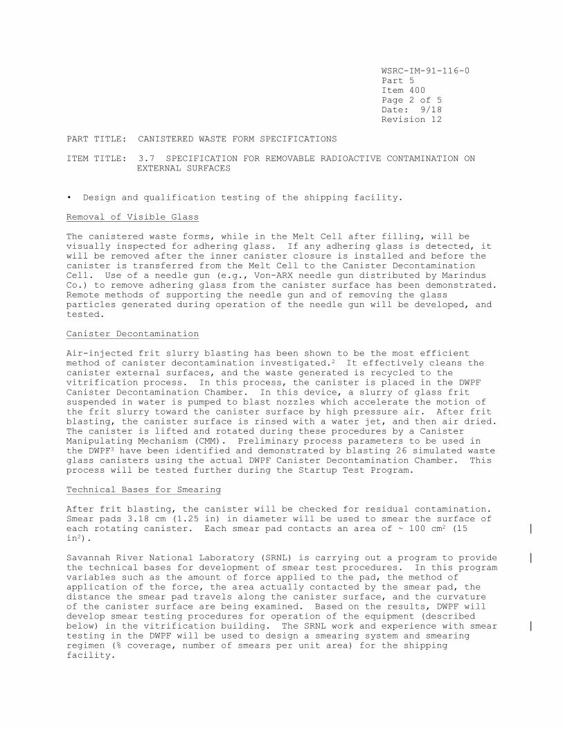
WSRC-IM-91-116-0
Part 5
Item 400
Page 2 of 5
Date: 9/18
Revision 12
PART TITLE: CANISTERED WASTE FORM SPECIFICATIONS
ITEM TITLE: 3.7 SPECIFICATION FOR REMOVABLE RADIOACTIVE CONTAMINATION ON
EXTERNAL SURFACES
• Design and qualification testing of the shipping facility.
Removal of Visible Glass
The canistered waste forms, while in the Melt Cell after filling, will be
visually inspected for adhering glass. If any adhering glass is detected, it
will be removed after the inner canister closure is installed and before the
canister is transferred from the Melt Cell to the Canister Decontamination
Cell. Use of a needle gun (e.g., Von-ARX needle gun distributed by Marindus
Co.) to remove adhering glass from the canister surface has been demonstrated.
Remote methods of supporting the needle gun and of removing the glass
particles generated during operation of the needle gun will be developed, and
tested.
Canister Decontamination
Air-injected frit slurry blasting has been shown to be the most efficient
method of canister decontamination investigated.2 It effectively cleans the
canister external surfaces, and the waste generated is recycled to the
vitrification process. In this process, the canister is placed in the DWPF
Canister Decontamination Chamber. In this device, a slurry of glass frit
suspended in water is pumped to blast nozzles which accelerate the motion of
the frit slurry toward the canister surface by high pressure air. After frit
blasting, the canister surface is rinsed with a water jet, and then air dried.
The canister is lifted and rotated during these procedures by a Canister
Manipulating Mechanism (CMM). Preliminary process parameters to be used in
the DWPF3 have been identified and demonstrated by blasting 26 simulated waste
glass canisters using the actual DWPF Canister Decontamination Chamber. This
process will be tested further during the Startup Test Program.
Technical Bases for Smearing
After frit blasting, the canister will be checked for residual contamination.
Smear pads 3.18 cm (1.25 in) in diameter will be used to smear the surface of
each rotating canister. Each smear pad contacts an area of ~ 100 cm2 (15
in2).
Savannah River National Laboratory (SRNL) is carrying out a program to provide
the technical bases for development of smear test procedures. In this program
variables such as the amount of force applied to the pad, the method of
application of the force, the area actually contacted by the smear pad, the
distance the smear pad travels along the canister surface, and the curvature
of the canister surface are being examined. Based on the results, DWPF will
develop smear testing procedures for operation of the equipment (described
below) in the vitrification building. The SRNL work and experience with smear
testing in the DWPF will be used to design a smearing system and smearing
regimen (% coverage, number of smears per unit area) for the shipping
facility.

WSRC-IM-91-116-0
Part 5
Item 400
Page 3 of 5
Date: 9/18
Revision 12
PART TITLE: CANISTERED WASTE FORM SPECIFICATIONS
ITEM TITLE: 3.7 SPECIFICATION FOR REMOVABLE RADIOACTIVE CONTAMINATION ON
EXTERNAL SURFACES
The canister will be transferred to the Weld Test Cell for final closure only
after all smear test results are within the specified limits. If any smear
exceeds specified limits, the canister will be decontaminated again by slurry-
blasting until the contamination level is within the specified limits.
(During production, DWPF will use the tighter limits of 2,200 dpm/100 cm2
beta/gamma and 220 dpm/100 cm2 alpha.) A confirmatory smear test will also be
made in the Weld Test Cell prior to transfer to interim storage in the DWPF's
Glass Waste Storage Building. A pneumatic transfer system is used to transfer
smear samples out of the shielded cells. The smear test is performed remotely
using manipulators with the aid of CCTV cameras and by direct observation
through shield windows. The control stations and the radio bench hood for
smear sample counting are located outside the cell in close proximity to
shield windows.
Canister Shipping Facility
Sometime in the future, a canister shipping facility will be designed and
built. The technical bases for smearing described above, as well as the
experience with the smear testing systems in the DWPF, will be used as design
input for the facility. Once built, it is anticipated that a qualification
program will be carried out, to ensure that the Shipping Facility's procedures
and equipment will satisfy the specification.
Documentation
Volume 11 of the Waste Form Qualification Report (WQR) will include a report
on the decontamination method, and the technique for removing visible waste
glass from the canister exterior. The WQR will also include the results of
the program to develop the technical bases for the smear test procedures.
The DWPF will report, in the Storage and Shipping Records, all smear test
results for each canister. If the canister contamination level cannot be
brought down to the DOE specified values, then the canistered waste form will
be identified as a nonconforming item, and dispositioned according to the
procedure outlined in Part 6, Item 300.
References
1. W. N. Rankin, "Decontamination Processes for Waste Glass Canisters,"
Nuclear Technology, 59, 314-20 (1982).
2. C. R. Ward, Selection and Development of Air-Injected Frit Slurry Blasting
for Decontamination of DWPF Canisters, USDOE Report DP-1692, E. I. Du Pont de
Nemours, Inc., Savannah River Laboratory, Aiken, SC 29808 (1984).

WSRC-IM-91-116-0
Part 5
Item 400
Page 4 of 5
Date: 9/18
Revision 12
PART TITLE: CANISTERED WASTE FORM SPECIFICATIONS
ITEM TITLE: 3.7 SPECIFICATION FOR REMOVABLE RADIOACTIVE CONTAMINATION ON
EXTERNAL SURFACES
3. A. H. Harris and C. R. Ward, Development and Demonstration of the DWPF
Canister Decontamination Process Using Frit Slurry Blasting, USDOE Report DP-
MS-86-128, E. I. Du Pont de Nemours, Inc., Savannah River Laboratory, Aiken,
SC 29808 (1986).

WSRC-IM-91-116-0
Part 5
Item 400
Page 5 of 5
Date: 9/18
Revision 12
PART TITLE: CANISTERED WASTE FORM SPECIFICATIONS
ITEM TITLE: 3.7 SPECIFICATION FOR REMOVABLE RADIOACTIVE CONTAMINATION ON
EXTERNAL SURFACES
FIGURE 5.400.1 Tasks planned to satisfy Specification 3.7, Specification for
Removable Radioactive Contamination on External Surfaces.
DWPF
Hot
Startup
Document development
of decontamination
method.
[SRNL]
Certify no visible glass
on canister exterior.
[DWPF]
Develop technique to
remove visible glass from
canister.
[SRNL]
Provide technical bases
for smear test
procedures.
[SRNL]
Demonstrate
functionality of
decontamination method.
[DWPF]
Demonstrate smear
testing.
[DWPF]
Design and qualify
canistered waste form
shipping facility
[DWPF]
Provide results of final
smear test before
shipment.
[DWPF]
WSRC-IM-91-116-0
Part 5
Item 450
Page 1 of 3
Date: 3/06
Revision 8
PART TITLE: CANISTERED WASTE FORM SPECIFICATIONS
ITEM TITLE: 3.8.1 HEAT GENERATION PROJECTIONS
3.8 HEAT GENERATION SPECIFICATION The heat generation rate for each canistered waste form shall not exceed 1500 watts per canister at the year of shipment.
3.8.1 Heat Generation Projections The Producer shall document in the WQR the expected thermal output of the canistered waste forms and the range of expected variation for each waste type, indexed to the year 2015. The method to be used for demonstrating compliance shall be described by the producer in the WCP. Projections for compositions not available for reporting in the initial WQR shall be included in an addendum to the WQR. Compliance Strategy
The expected thermal output and the range of expected variations for the
canistered waste forms will be calculated based on the radionuclide inventory
projections described in Part 3, Item 300.
Implementation
As shown in Figure 5.450.1, this specification will be satisfied by
• Providing the radionuclide inventory projections as described in Part 3,
Item 300.
• Converting the radionuclide inventory projections into projections of heat
generation rates for each waste type. This will be done by multiplying the
amount of each radionuclide by its specific thermal output, using standard
values.
• Estimating the range of values for each waste type by bounding
calculations.
Calculation of Heat Generation Rates
For each of the waste types identified in Part 3, Item 300, the heat
generation rate will be calculated from the radionuclide inventory of the
glass, using standard values of the thermal output per unit activity for each
radionuclide. The radionuclides which will be included in performing this
calculation will be all of those radionuclides to be reported to the
repository as part of the radionuclide inventory (see Part 3, Item 400), and
any other short-lived radionuclides in the Design-Basis waste which
significantly contribute to the heat generation rate. Preliminary
Those with half-lives greater than 10 years and which constitute at least
0.01% of the radionuclide inventory at any time up to 1100 years after
production.

WSRC-IM-91-116-0
Part 5
Item 450
Page 2 of 3
Date: 3/06
Revision 8
PART TITLE: CANISTERED WASTE FORM SPECIFICATIONS
ITEM TITLE: 3.8.1 HEAT GENERATION PROJECTIONS
calculations indicate that the latter will be of importance only for waste
which is 10 years old or less.
Estimation of Ranges of Heat Generation Rates
The range of the heat generation rates for each waste type will be provided
through simple bounding calculations. The lower bound for each waste type is
assumed to be glass which contains no radionuclides, either due to melter
startup (when actual waste glass is displacing simulated waste glass), or due
to flushing operations (e.g., when a melter is about to be taken out of
service). The upper bound will be estimated by assuming a 90% fill of a
glass which contains the maximum amount of waste which will produce an
acceptable glass (based on the algorithms described in Part 3, Item 500).
Documentation
Volume 3 of the Waste Form Qualification Report will detail the expected
thermal output and the range of expected variations for the canistered waste
forms.
References
1. Integrated Data Base for 1991: Spent Fuel and Radioactive Waste Inventories, Projections, and Characteristics, USDOE Report RW-0006, Revision 7.

WSRC-IM-91-116-0
Part 5
Item 450
Page 3 of 3
Date: 3/06
Revision 8
PART TITLE: CANISTERED WASTE FORM SPECIFICATIONS
ITEM TITLE: 3.8.1 HEAT GENERATION PROJECTIONS
FIGURE 5.450.1 Tasks planned to satisfy Specification 3.8.1, Heat Generation
Projections.
Estimate range of
thermal output for
each waste
type.[SRNL]
DWPF
Hot Startup
Estimate thermal
output for each waste
type. [SRNL]
Estimate radionuclide
inventory (see Part 3,
Item 300)
[SRNL]

WSRC-IM-91-116-0
Part 5
Item 500
Page 1 of 3
Date: 4/99
Revision 6
PART TITLE: CANISTERED WASTE FORM SPECIFICATIONS
ITEM TITLE: 3.8.2 HEAT GENERATION AT YEAR OF SHIPMENT
3.8 HEAT GENERATION SPECIFICATION 3.8.2 Heat Generation at Year of Shipment The Producer shall report in the Storage and Shipping Records the estimated heat generation rate for each canistered waste form. The Producer shall describe the method for compliance in the WCP.
Compliance Strategy
The heat generation rate of each canistered waste form will be calculated
based on the radionuclide inventory described in Part 3, Item 400, augmented
by analytical results for short-lived radionuclides (measured for process
safety reasons). Thus, in the Storage and Shipping Records, the DWPF will
report the average heat generation rate, and the standard deviation, for all
the canisters produced from a given macro-batch. If, at time of proposed
shipment, a canistered waste form has a heat generation rate greater than 1500
watts, the canistered waste form will be identified as a nonconforming item,
and dispositioned as outlined in Part 6, Item 300.
Implementation
The tasks planned to satisfy this specification are outlined in
Figure 5.500.1. They are to calculate the heat generation rate from the
radionuclide inventory, and to estimate the error in the method of
calculation.
Calculation of Heat Generation Rate
The heat generation rate will be calculated from the radionuclide inventory of
the glass, using standard values of the thermal output per unit activity for
each radionuclide. The radionuclides which will be included in performing
this calculation will be all of those radionuclides to be reported to the
repository as part of the radionuclide inventory (see Part 3, Item 400), and
any other radionuclides analyzed for process safety purposes in the DWPF (e.g.
Pr-144, Eu-154, or Eu-155). Preliminary calculations indicate that the latter
will be of importance only for waste which is 10 years old or less.
Because the radionuclide inventory is reported on a macro-batch basis, the
heat generation rate will also be reported in that manner. Each radionuclide
inventory value estimated from process batches for a given macro-batch will be
used to generate a heat generation rate. These heat generation rates will
then be averaged, and a standard deviation calculated. This average heat
generation rate and standard deviation will then be reported for each canister
of the macro-batch.
If the heat generation rate exceeds 1500 watts (taking into account the
uncertainty in the calculated value) at time of shipment of the canister from
* Those with half-lives greater than 10 years and which constitute at least 0.01% of the radionuclide inventory at any time up to 1100 years after
production.

WSRC-IM-91-116-0
Part 5
Item 500
Page 2 of 3
Date: 4/99
Revision 6
PART TITLE: CANISTERED WASTE FORM SPECIFICATIONS
ITEM TITLE: 3.8.2 HEAT GENERATION AT YEAR OF SHIPMENT
the DWPF, the canister will be identified as a nonconforming item, and then
dispositioned according to the procedure outlined in Part 6, Item 300.
Estimates of Error
Preliminary calculations have already been performed for the Design-Basis
glass. At time of production, the heat generation rate of the glass is
calculated to be 710 watts/canistered waste form. The dominant source of
error in the calculation is the radionuclide inventory. The current estimates
of uncertainties in the radionuclide inventory in Part 3, Item 400, indicate
that the calculated heat generation rate will be within 10% of the actual
value (There will be a slight bias in the reported values; less than about 15
watts for the worst case).
Documentation
Volume 12 of the Waste Form Qualification Report will include a description of
the heat generation rate calculation, the results of tests to determine the
error in the reported values, and an estimation of the error.
The Storage and Shipping Record for each canistered waste form will include
the heat generation rate as calculated from the radionuclide inventory of the
glass.
References
1. Integrated Data Base for 1991: Spent Fuel and Radioactive Waste Inventories, Projections, and Characteristics, USDOE Report RW-0006, Revision 7 (1992).


WSRC-IM-91-116-0
Part 5
Item 550
Page 1 of 4
Date: 3/06
Revision 8
PART TITLE: CANISTERED WASTE FORM SPECIFICATIONS
ITEM TITLE: 3.9.1 PROJECTIONS OF DOSE RATES
3.9 SPECIFICATION FOR MAXIMUM DOSE RATES The canistered waste form shall not exceed a maximum surface (on contact) gamma dose rate of 10 rem/hr and a maximum neutron dose rate of 10 rem/hr, at
the time of shipment. 3.9.1 Projections of Dose Rates The Producer shall report in the WQR the expected values and the range of expected variation for both gamma and neutron dose rates indexed to the year 2015. The Producer shall describe the method for demonstrating compliance in the WCP.
Compliance Strategy
The expected dose rates and the range of expected variation will be calculated
based on the radionuclide inventory projections described in Part 3, Item 300.
Implementation
As shown in Figure 5.500.1, this specification will be satisfied by
• Providing the radionuclide inventory projections for each waste type as
described in Part 3, Item 300.
• Converting the radionuclide inventory projections into projections of dose
rates for each waste type.
• Estimating the range of values for the canistered waste forms of each waste
type by bounding calculations.
Calculation of Dose Rates
The values required by this specification will be determined by converting the
radionuclide inventory projections described in Part 3, Item 300, into
corresponding projections of neutron and gamma dose rates. This will be done
by multiplying the amount of each radionuclide by its dose rate per curie.
Self-shielding and shielding by the canister will also be taken into account.
Preliminary estimates of the maximum dose rates of DWPF canistered waste forms
have already been made. These have been calculated from the composition and
radionuclide inventory of the Design-Basis waste glass. These calculations
are summarized in Table 5.550.1.

WSRC-IM-91-116-0
Part 5
Item 550
Page 2 of 4
Date: 3/06
Revision 8
PART TITLE: CANISTERED WASTE FORM SPECIFICATIONS
ITEM TITLE: 3.9.1 PROJECTIONS OF DOSE RATES
Estimation of Ranges of Dose Rates
The range of the dose rates for the canistered waste forms of each waste type
will be provided through simple bounding calculations. The lower bound will
be estimated by assuming that the glass contains virtually no waste (e.g.,
melter changeout). The upper bound will be estimated by assuming a 90% fill
of a glass which contains the maximum amount of waste which will produce an
acceptable glass.
Documentation
Volume 3 of the Waste Form Qualification Report will include a report on the
projections of gamma and neutron dose rates, and their expected variations.
Results of tests of the calculational methods will also be reported, including
the experimental verification of the SRS neutron dose rate calculations.

WSRC-IM-91-116-0
Part 5
Item 550
Page 3 of 4
Date: 3/06
Revision 8
PART TITLE: CANISTERED WASTE FORM SPECIFICATIONS
ITEM TITLE: 3.9.1 PROJECTIONS OF DOSE RATES
TABLE 5.550.1 Calculated maximum gamma and neutron dose rates of DWPF
canistered waste forms (based on Design-Basis Glass).
Distance (ft) Gamma(R/hr) Neutrons(mrem/hr) Total (R/hr)
Surface 5570 420. 5570
1 2190 97. 2190
3 900 42. 900
5 470 23. 470
10 160 7.5 160
20 44 2.5 44
30 20 1.0 20
50 7 0.5 7
75 3 --- 3
100 2 --- 2

WSRC-IM-91-116-0
Part 5
Item 550
Page 4 of 4
Date: 3/06
Revision 8
PART TITLE: CANISTERED WASTE FORM SPECIFICATIONS
ITEM TITLE: 3.9.1 PROJECTIONS OF DOSE RATES
FIGURE 5.550.1 Tasks planned to satisfy Specification 3.9.1, Projections of
Dose Rates.
Estimate radionuclide
inventory
(see Part 3, Item 300).
[SRNL]
Estimate dose rate
for each waste type.
[SRNL]
Estimate range of
dose rates for
canistered waste
forms. [SRNL]
DWPF
Hot Startup

WSRC-IM-91-116-0
Part 5
Item 600
Page 1 of 3
Date: 9/99
Revision 6
PART TITLE: CANISTERED WASTE FORM SPECIFICATIONS
ITEM TITLE: 3.9.2 DOSE RATES AT TIME OF SHIPMENT
3.9 SPECIFICATION FOR MAXIMUM DOSE RATES 3.9.2 Dose Rates at Time of Shipment
The Producer shall provide in the Storage and Shipping Records either the calculated or measured values for both gamma and neutron dose rates at the time of shipment for each canistered waste form. The Producer shall describe the method of compliance in the WCP.
Compliance Strategy
The DWPF will comply with the specification be measuring the dose rates from
canistered waste forms in the shipping facility prior to shipment. (It must
be noted that this facility does not yet exist.) Additional assurance that
the canistered waste forms do not exceed the specified dose rates will be
provided by dose rate measurements in the DWPF.
Implementation
The tasks planned to satisfy this specification are outlined in Figure
5.600.1. They are
Identification of methods to measure the neutron and gamma dose rates of
the canistered waste form.
Design, construction, and qualification testing of the shipping facility.
Measurement of Gamma and Neutron Dose Rates
Prior to the initiation of production, methods for measuring the gamma and
neutron dose rates of the canistered waste forms will be identified. Standard
techniques and instruments will be adapted to this task. Appropriate
technologies will be described in the Waste Form Qualification Report, to
establish the existence of methods which could be successfully deployed in a
Shipping Facility.
Design and Qualification Testing of the Shipping Facility
Sometime in the future, a canister shipping facility will be designed and
built. The instruments used at SRS to measure gamma and neutron dose rates,
as well as the operating experience with those instruments, will be used as
design input for the facility. Once built, it is anticipated that the
procedures and equipment will satisfy the specification.
Documentation
Volume 12 of the Waste Form Qualification Report will include a description of
instruments which could be used to measure the gamma and neutron dose rates of
DWPF canistered waste forms. Eventually, the results of qualification testing
of a Shipping Facility will be added to Volume 12.

WSRC-IM-91-116-0
Part 5
Item 600
Page 2 of 3
Date: 9/99
Revision 6
PART TITLE: CANISTERED WASTE FORM SPECIFICATIONS
ITEM TITLE: 3.9.2 DOSE RATES AT TIME OF SHIPMENT
The Storage and Shipping Record for each canistered waste form will include
the gamma and neutron dose rates of the canistered waste form as determined in
the DWPF shipping facility.
If the measured dose rates exceed 10 R/hr surface gamma dose rate, or 10
rem/hr neutron dose rate, then the canistered waste form will be identified as
a nonconforming item, and dispositioned according to the procedure outlined in
Part 6, Item 300.

WSRC-IM-91-116-0
Part 5
Item 600
Page 3 of 3
Date: 9/99
Revision 6
PART TITLE: CANISTERED WASTE FORM SPECIFICATIONS
ITEM TITLE: 3.9.2 DOSE RATES AT TIME OF SHIPMENT
FIGURE 5.600.1 Tasks planned to satisfy Specification 3.9.2, Dose Rates at
Time of Shipment.
DWPF
Hot
Startup
Identify methods to
determine dose rates.
[DWPF]
Design and qualify
canistered waste form
shipping facility.
[DWPF]
Report gamma and neutron
dose rates.
[DWPF]

WSRC-IM-91-116-0
Part 5
Item 650
Page 1 of 3
Date: 6/16
Revision 11
PART TITLE: CANISTERED WASTE FORM SPECIFICATIONS
ITEM TITLE: 3.10 SUBCRITICALITY SPECIFICATION
3.10 SUBCRITICALITY SPECIFICATION The Producer shall design a waste form to ensure that, under normal and accident conditions, a nuclear criticality accident is not possible unless at least two unlikely, independent, and concurrent or sequential changes have occurred in the conditions essential to nuclear criticality safety. The calculated effective multiplication factor, k , shall be sufficiently below
unity to show at least a 5% margin after allowing for bias in the method of calculation and the uncertainty in the experiments used to validate the method of calculation. The Producer shall describe the method of demonstrating compliance in the WCP and provide supporting documentation in the WQR. The WQR shall also include sufficient information on the nuclear characteristics, such as fissile density, of the canistered waste form to enable subcriticality to be confirmed under transportation, storage and disposal conditions.
Compliance Strategy
The DWPF will comply with the specification by performing bounding
calculations to show that the effective multiplication factor for a canistered
waste form will be much less than 1.
Implementation
The tasks sufficient to satisfy this specification are outlined in Figure
5.650.1. They include
• Development of the radionuclide inventory projections, as described in Part
3, Item 300.
• A determination of the nuclear characteristics of DWPF canistered waste
forms, based on the projected radionuclide inventories. This includes
identification of bounding case(s).
• Calculation of k for the bounding case(s).
Bounding Cases for DWPF Canistered Waste Forms
A k calculation was included in the DWPF facility's nuclear safety analysis
prior to finalization of the DWPF design. The calculation was made on both
Design-Basis glass, and on a glass containing twice as much fissionable
material as the Design-Basis glass. An infinite array of canisters was
assumed in the calculations which would bound any finite array of canisters in
any arrangement including double stacking of canisters, and flooding was
considered. These would constitute at least two unlikely, independent, and
concurrent or sequential changes in the conditions essential to nuclear
criticality safety.
In all cases the calculated neutron multiplication factor was quite low, k
< 0.15. Doubling the plutonium and the U concentrations (with the other
constituents reduced proportionately for normality), increased k to 0.273,
but this value is low enough to provide an ample safety margin.

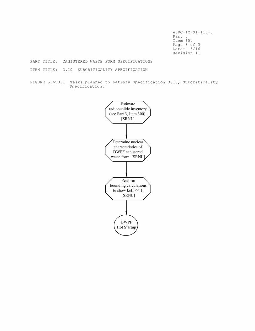
WSRC-IM-91-116-0
Part 5
Item 650
Page 3 of 3
Date: 6/16
Revision 11
PART TITLE: CANISTERED WASTE FORM SPECIFICATIONS
ITEM TITLE: 3.10 SUBCRITICALITY SPECIFICATION
FIGURE 5.650.1 Tasks planned to satisfy Specification 3.10, Subcriticality
Specification.
Determine nuclear
characteristics of
DWPF canistered
waste form. [SRNL]
Perform
bounding calculations
to show keff << 1.
[SRNL]
DWPF
Hot Startup
Estimate
radionuclide inventory
(see Part 3, Item 300).
[SRNL]

WSRC-IM-91-116-0
Part 5
Item 700
Page 1 of 4
Date: 9/99
Revision 6
PART TITLE: CANISTERED WASTE FORM SPECIFICATIONS
ITEM TITLE: 3.11 SPECIFICATIONS FOR WEIGHT AND OVERALL DIMENSIONS
3.11 SPECIFICATIONS FOR WEIGHT AND OVERALL DIMENSIONS The configuration, dimensions, and weight of the canistered waste form shall not exceed the maximum size and weight which can be received, handled, and emplaced in the repository. These parameters shall be controlled as indicated below and shall be documented at the time of shipment. The Producer shall describe the method of compliance in the WCP and the basis for compliance in
the WQR. 3.11.1 Weight Specification The weight of the canistered waste form shall not exceed 2,500 kg. The measured weight and estimated error shall be reported in the Storage and Shipping Records. 3.11.2 Specification for Overall Dimensions The dimensions of the canistered waste form shall be such that, at the time of delivery, the canistered waste form will stand upright without support on a flat horizontal surface and will fit completely without forcing when lowered vertically into a right-circular, cylindrical cavity, 64.0 cm in diameter and 3.01 m in length. The Producer shall estimate in the WQR the minimum canister wall thickness of the filled, decontaminated canister. The Producer shall also provide in the WQR an estimate of the amount of canister material that is removed during surface decontamination and the basis for that estimate. The Producer shall document the unfilled canister wall thickness in the Production Records. Compliance Strategy
The final weight of each DWPF canistered waste form will be measured in a
shipping facility, prior to shipment from the DWPF to a repository.
Measurements of non-radioactive canistered waste forms produced under
conditions representing the range of those expected in the DWPF show that the
vitrification process does not significantly affect the dimensions of the
canistered waste form (see Part 4, Item 400). Thus, the DWPF will ensure that
the overall dimensions of the canistered waste form are within the specified
limits by controlling the dimensions of the purchased canister. The minimum
wall thickness is 0.340 inches (0.86 cm), based on the canister procurement
specifications and the fact that the vitrification process does not reduce
canister wall thickness.
Implementation
The tasks planned to satisfy this specification are outlined in Figure
5.700.1. These are
• Development of a requirement for the canister wall thickness, which has
been included in the canister procurement specifications. This also includes
identification of canister inspection requirements to ensure that the
specification is met at the vendor's shop.

WSRC-IM-91-116-0
Part 5
Item 700
Page 2 of 4
Date: 9/99
Revision 6
PART TITLE: CANISTERED WASTE FORM SPECIFICATIONS
ITEM TITLE: 3.11 SPECIFICATIONS FOR WEIGHT AND OVERALL DIMENSIONS
• Determination of the amount of material removed from the canister wall.
• Determination of the change in canister wall thickness and overall
dimensions during glass pouring at the pilot plant facilities.
• Design and qualification testing of a shipping facility.
Canister Procurement Specifications
The DWPF has developed detailed canister procurement specifications which
specify the wall thickness and overall dimensions of canisters. In addition,
inspection requirements are being defined, to ensure that the purchased
canisters actually meet specifications before they leave the vendor's shop.
Change in Dimension During Pouring
As discussed in Part 4, Item 400, seven prototypical canisters were carefully
measured and then filled under both design basis (continuously filling) and
the most likely upset (pouring rapidly in short bursts) conditions. The
calculated diameter of a cylinder large enough to contain the canister, taking
into account ovality and bow was determined to be 24.21 inches (61.49 cm).
This maximum cylinder diameter is within the specified limit of specification
3.11.2. The WQR will provide the technical basis for this conclusion, and the
details of the measurements and calculations.
The weights of the prototypical canistered waste forms were also measured.
The average weight of the glass was ~1680 kg. The average weight of the
canister was ~500 kg. Thus, the total weight of each simulated canistered
waste form was ~2180 kg, indicating that the DWPF should have little
difficulty in meeting the weight specification.
If it was necessary to use a repair cap for the final canister weld (see Part
4, Item 200) the canistered waste form would not fit within the specified
right circular cylinder. This canistered waste form would then be identified
as a nonconforming item, and dispositioned according to the procedure outlined
in Part 6, Item 300.
Metal Removal During Decontamination
Based on process development work at SRTC, a single slurry frit blasting cycle
will remove 70 g of canister material (metal and contaminated oxides), or
approximately 2 mg/cm of canister surface area (This corresponds to a
penetration of ~0.2 µm.). It has been shown that a conservative estimate of
the minimum metal removal required to achieve the specified level of
decontamination is 1 mg/cm .
Design, and Qualification Testing of the Shipping Facility
The weight of the canistered waste form will be determined in a canister
shipping facility prior to shipment to a repository. In addition, the overall
dimensions of the canistered waste form will also be verified in the shipping
facility prior to shipment. This will be done either through use of a

WSRC-IM-91-116-0
Part 5
Item 700
Page 3 of 4
Date: 9/99
Revision 6
PART TITLE: CANISTERED WASTE FORM SPECIFICATIONS
ITEM TITLE: 3.11 SPECIFICATIONS FOR WEIGHT AND OVERALL DIMENSIONS
template to ensure the right cylindricality and proper diameter and length of
the canister, or through measurements. No dimensional changes in the
canistered waste form are expected between the time of shipment from DWPF and
the time of delivery at the repository. It is anticipated that a
qualification program of the systems to measure canister weight and the
overall dimensions of the canister will be carried out, to ensure that the
procedures and equipment will satisfy the specification.
Documentation
Volume 8 of the Waste Form Qualification Report will reference the canister
procurement specifications, and inspection procedures. The WQR will also
include a report on the effect of the vitrification process on the canistered
waste form dimensions. A report on the amount of material removed during
decontamination will also be included.
The Production Record for each canistered waste form shall contain the as-
purchased wall thickness of the canister.
The Storage and Shipping Record for each canistered waste form will include
the weight and a determination of the ability of the canister to fit without
forcing into the specified cylinder. The weight will be obtained by weighing
in the shipping facility. The ability of the glass-filled canisters to fit
without forcing into the specified cylinder will be certified at time of
shipment either based on the ability of the canister to fit, without forcing,
into a template of the specified cylinder, or based on calculation of the
minimum cylinder which can contain the canister.
If the canister weight exceeds the specified amount or the canister cannot fit
in the specified cylinder, then the canistered waste form will be identified
as a nonconforming item, and dispositioned according to the procedure outlined
in Part 6, Item 300.

WSRC-IM-91-116-0
Part 5
Item 700
Page 4 of 4
Date: 9/99
Revision 6
PART TITLE: CANISTERED WASTE FORM SPECIFICATIONS
ITEM TITLE: 3.11 SPECIFICATIONS FOR WEIGHT AND OVERALL DIMENSIONS
FIGURE 5.700.1 Tasks planned to satisfy Specification 3.11, Specifications
for Weight and Overall Dimensions.
Specify wall
thickness in canister
procurement
documents. [DWPF]
Report as purchased
wall thickness.
[DWPF]
DWPF
Hot Startup
Determine amount
of canister material removed
during decontamination.
[SRTC]
Determine change
in dimensions during
pouring (see Part 4,
Item 400). [SRTC]
Design and qualify
canistered waste form
shipping facility.
[DWPF]
Report weight, errors, and
certification of ability to
fit within specified
cylinder. [DWPF]


WSRC-IM-91-116-0
Part 5
Item 750
Page 2 of 3
Date: 9/99
Revision 6
PART TITLE: CANISTERED WASTE FORM SPECIFICATIONS
ITEM TITLE: 3.12 DROP TEST SPECIFICATION
decontamination process, and sealed in the same manner as in the DWPF (in some
cases, with actual DWPF equipment).
Testing of Canisters and Effects of Impacts
Strain circles were applied to the canister surface to indicate the magnitude
of the strains exerted on the canisters during impact. These canisters were
dropped from 7 m, in two orientations:
• The most likely - on the bottom.
• The most severe - on the head at an angle.
Each canister was tested by dye penetrant methods. Helium leak rate
measurements were also made. All of the canisters survived the impacts
without breaching.
Documentation
Volume 8 of the Waste Form Qualification Report (WQR) will include a report on
the bases of the drop tests, the results of the drop tests, and the effects of
the impacts on the canister's leaktightness, dimensions, and integrity.
References
1. J. W. Kelker, SRL Canister Impact Tests, USDOE Report DP-1716, E. I. DuPont de Nemours, Inc., Savannah River Laboratory, Aiken SC (1986).
2. K. M. Olson, J. M. Alzheimer, Defense Waste Processing Facility Canister Impact Testing, Pacific Northwest Laboratory, Richland, WA (1989).

WSRC-IM-91-116-0
Part 5
Item 750
Page 3 of 3
Date: 9/99
Revision 6
PART TITLE: CANISTERED WASTE FORM SPECIFICATIONS
ITEM TITLE: 3.12 DROP TEST SPECIFICATION
FIGURE 5.750.1 Tasks planned to satisfy Specification 3.12, Drop Test
Specification.
Control canister
procurement (See Part 4,
Items 100, 200, 400;
Part5, Item 700). [DWPF]
Produce prototypic
filled canisters.
[SRTC]
Measure leak rates
and canister
deformation after drop
tests. [SRTC]
DWPF
Hot Startup
Perform required
drop test on
prototypic canisters.
[SRTC]
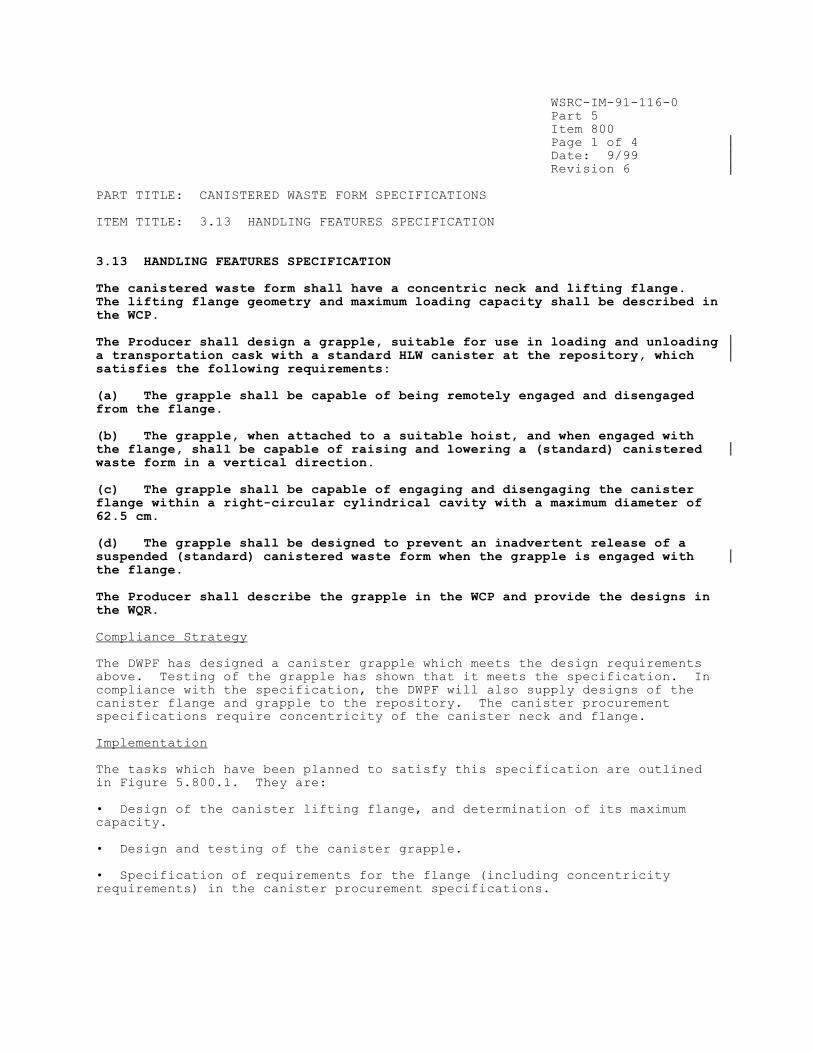
WSRC-IM-91-116-0
Part 5
Item 800
Page 1 of 4
Date: 9/99
Revision 6
PART TITLE: CANISTERED WASTE FORM SPECIFICATIONS
ITEM TITLE: 3.13 HANDLING FEATURES SPECIFICATION
3.13 HANDLING FEATURES SPECIFICATION The canistered waste form shall have a concentric neck and lifting flange. The lifting flange geometry and maximum loading capacity shall be described in the WCP. The Producer shall design a grapple, suitable for use in loading and unloading
a transportation cask with a standard HLW canister at the repository, which satisfies the following requirements: (a) The grapple shall be capable of being remotely engaged and disengaged from the flange. (b) The grapple, when attached to a suitable hoist, and when engaged with the flange, shall be capable of raising and lowering a (standard) canistered waste form in a vertical direction. (c) The grapple shall be capable of engaging and disengaging the canister flange within a right-circular cylindrical cavity with a maximum diameter of 62.5 cm. (d) The grapple shall be designed to prevent an inadvertent release of a suspended (standard) canistered waste form when the grapple is engaged with the flange. The Producer shall describe the grapple in the WCP and provide the designs in the WQR.
Compliance Strategy
The DWPF has designed a canister grapple which meets the design requirements
above. Testing of the grapple has shown that it meets the specification. In
compliance with the specification, the DWPF will also supply designs of the
canister flange and grapple to the repository. The canister procurement
specifications require concentricity of the canister neck and flange.
Implementation
The tasks which have been planned to satisfy this specification are outlined
in Figure 5.800.1. They are:
• Design of the canister lifting flange, and determination of its maximum
capacity.
• Design and testing of the canister grapple.
• Specification of requirements for the flange (including concentricity
requirements) in the canister procurement specifications.

WSRC-IM-91-116-0
Part 5
Item 800
Page 2 of 4
Date: 9/99
Revision 6
PART TITLE: CANISTERED WASTE FORM SPECIFICATIONS
ITEM TITLE: 3.13 HANDLING FEATURES SPECIFICATION
Canister Lifting Flange
The lifting flange geometry for the DWPF canister is shown in Figure 5.800.2;
more detail is available from DWPF drawing #W832094, including method of
attachment to the canister. This drawing is referenced in the canister
procurement specifications, which require that the canister neck and lifting
flange be concentric. Calculations estimate its maximum loading capacity as
15,000 lbs. These calculations will be included in the Waste Form
Qualification Report.
Design and Testing of Canister Grapple
The canister lifting grapple is specific for the DWPF canister and was
developed by Remote Technology Corp. (REMOTEC) of Oak Ridge, TN. The
canister grapple is capable of remotely picking up a canister, transporting it
to a new location and releasing. The grapple lifting lug configuration and
operation is designed to minimize canister damage which could affect the
welding ground path during final canister closure operations. The grapple is
designed without any electrical power source and uses a mechanical linkage to
positively secure the canister. A more detailed description of the grapple's
design features, and of the testing of the grapple, will be provided in the
Waste Form Qualification Report.
Documentation
Volume 8 of the Waste Form Qualification Report will include descriptions and
detailed drawings of the designs of the lifting flange and grapple. Test data
from development and operability testing of the grapple will be included as
well. A report detailing the calculation of the loading capacity of the
canister neck and lifting flange will also be provided.
References
1. K. L. Walker, J. R. White, K. A. Farnstrom, R. E. Eversole, "Canister
Grapple for the Defense Waste Processing Facility," Proceedings, 34th Conference on Remote Systems Technology, American Nuclear Society, 75-9 (1986).

WSRC-IM-91-116-0
Part 5
Item 800
Page 3 of 4
Date: 9/99
Revision 6
PART TITLE: CANISTERED WASTE FORM SPECIFICATIONS
ITEM TITLE: 3.13 HANDLING FEATURES SPECIFICATION
FIGURE 5.800.1 Tasks planned to satisfy Specification 3.13, Handling Features
Specification.
Design canister lifting
flange and determine
maximum load capacity.
[DWPF]
Design grapple
for lifting canisters.
[DWPF]
Specify lifting
flange requirements in
canister procurement
documents. [DWPF]
DWPF
Hot Startup
Test grapple.
[DWPF]


WSRC-IM-91-116-0
Part 6
Item 100
Page 1 of 6
Date: 9/99
Revision 6
PART TITLE: QUALITY ASSURANCE SPECIFICATIONS
ITEM TITLE: 4. QUALITY ASSURANCE SPECIFICATION
4. QUALITY ASSURANCE SPECIFICATION The Producer shall establish, maintain and execute a quality assurance (QA) program that applies to the testing and analysis activities that demonstrate compliance with these EM-WAPS during waste form qualification, production, acceptance, handling, storage, and preparation for shipment. The Producer shall impose a QA program consistent with the QA requirements that govern HLW
as identified in the RW Quality Assurance Requirements and Description (QARD) and the Civilian Radioactive Waste Management System’s Waste Acceptance Systems Requirements Document (WA-SRD) .
Compliance Strategy
The DWPF will comply with the specification by developing a QA program which
implements the requirements passed down by the Department of Energy’s Office
of Environmental Management line organization. Organizational interfaces and
departmental responsibilities are implemented through procedures.
The Waste Form Compliance Plan will be used to determine which items and
activities are included in the program. Since some of the data relevant to
compliance with the WAPS were collected prior to imposition of controls by the
Civilian Radioactive Waste Management System, an important part of the program
is to identify methods for qualification of existing data. Given the
likelihood of further changes in the quality assurance requirements, these
same controls will be used to qualify data generated under previous quality
assurance programs.
Implementation
The plan being followed to satisfy this specification is outlined in Figure
6.100.1. The plan includes the following elements:
• Preparation of the Waste Form Compliance Plan.
• Identification of items and activities which are important to compliance
with the WAPS. These are called Waste Acceptance Process items and
activities.
• Development and implementation of a Quality Assurance program which
satisfies the specification.
• Preparation of the Waste Form Qualification Report.
• Development of a plan for qualification of data collected prior to
initiation of the current QA program.
• Performance of a readiness review prior to radioactive waste form
production.
* U.S. Department of Energy, Office of Civilian Radioactive Waste Management, Quality Assurance Requirements and Description of the Civilian Radioactive Waste Management Program, U.S. DOE Document Number DOE/RW-0333P. **
U.S. Department of Energy, Office of Civilian Radioactive Waste Management, Waste Acceptance System Requirements Document, U.S. DOE Document Number DOE/RW-0351P.

WSRC-IM-91-116-0
Part 5
Item 850
Page 1 of 3
Date: 9/18
Revision 12
PART TITLE: CANISTERED WASTE FORM SPECIFICATIONS
ITEM TITLE: 3.14 CONCENTRATION OF PLUTONIUM IN EACH CANISTER SPECIFICATION
3.14 CONCENTRATION OF PLUTONIUM IN EACH CANISTER SPECIFICATION
The concentration of plutonium in each HLW standard canister shall be less
than 2,500 grams/cubic meter.
Compliance Strategy
The plutonium concentration limit specification requires the comparison of the
canister’s concentration of plutonium in grams per cubic meter to the
International Atomic Energy Agency (IAEA) limit of 2,500 grams/cubic meter.
The DWPF will determine the plutonium concentration in each DWPF canister as
described in Part 3, Item 800. The comparison with 2,500 grams/cubic meter
will validate that the DWPF canisters meet the IAEA requirement for plutonium
content.
Implementation
The tasks planned to satisfy this specification are outlined in Figure
5.850.1. Prior to satisfying specification 3.14, the tasks required to
satisfy specification 1.6 (specifically, the reporting of the plutonium
concentration per canister) must be completed (see Part 3, Item 800).
Determining the Total Plutonium Concentration Per Canister
Part 3, Item 800 provides a discussion of the methods that the DWPF uses to
determine the plutonium content in grams/cubic meter.
Glass Sampling
At least one glass pour stream sample will be taken by DWPF during the
processing of each sludge batch, analyzed as necessary and archived at the
SRNL Shielded Cells Facility. These samples may be characterized should
additional testing requirements be identified in the future but are no longer
required for batch sampling confirmation.
Documentation
Volume 4 of the Waste Form Qualification Report will contain a discussion of
the IAEA requirement limiting the total Pu concentration per canister to less
than 2,500 grams/cubic meter.
The Production Record for each canistered waste form will include the
following:
• total plutonium content per canister expressed as grams/m3
• comparison with the IAEA limit of 2,500 grams/m3

WSRC-IM-91-116-0
Part 5
Item 850
Page 2 of 3
Date: 9/18
Revision 12
PART TITLE: CANISTERED WASTE FORM SPECIFICATIONS
ITEM TITLE: 3.14 CONCENTRATION OF PLUTONIUM IN EACH CANISTER SPECIFICATION
The plutonium concentration used in the comparison will be reported as a
single value for each canister in the entire macro-batch.

WSRC-IM-91-116-0
Part 5
Item 850
Page 3 of 3
Date: 9/18
Revision 12
PART TITLE: CANISTERED WASTE FORM SPECIFICATIONS
ITEM TITLE: 3.14 CONCENTRATION OF PLUTONIUM IN EACH CANISTER SPECIFICATION
FIGURE 5.850.1 Tasks planned to satisfy Specification 3.14, Concentration of
Plutonium in each Canister Specification.
DWPF
Hot
Startup
Supplement radionuclide
inventory strategy (see
Part 3, Item 400)
[DWPF]
Confirm reported
Pu concentration is less
than 2,500g/m3
[DWPF]
Confirm reported
radionuclide inventory
using glass samples*
[SRNL]
*Beginning with Sludge Batch 9, glass samples will be archived at SRNL and
only characterized upon request.
WSRC-IM-91-116-0
Part 6
Item 100
Page 2 of 6
Date: 9/99
Revision 6
PART TITLE: QUALITY ASSURANCE SPECIFICATIONS
ITEM TITLE: 4. QUALITY ASSURANCE SPECIFICATION
Preparation of the Waste Form Compliance Plan
The WCP is an essential first step for implementation of the Quality Assurance
program related to waste form production. As the plan for compliance with the
WAPS, it defines the scope to which the Quality Assurance program applies. The
WCP has been prepared by the DWPF with the assistance of the Savannah River
Technology Center (SRTC). The WCP is issued and maintained by the DWPF, and
revised as necessary. The first version of the WCP was prepared in 1986, and
has been updated periodically since that time. Since 1990, major revisions of
the WCP have undergone independent technical review by DOE’s Waste Acceptance
Technical Review Group (TRG). This group, with joint sponsorship and
participation by DOE’s Offices of Civilian Radioactive Waste Management (RW),
and Environmental Management, is responsible for independently assessing the
technical adequacy of the WCP, and other Waste Acceptance Process documents.
Identification of Waste Acceptance Process Items and Activities
The purpose of identifying items and activities is to signify their importance
to Waste Acceptance Process objectives, so that appropriate mechanisms can be
established for their control. The DWPF has used the WCP to identify Waste
Acceptance Process items and activities (i.e., to identify the scope of the QA
program designed to meet the specification). Included in this set of items
and activities are
• All activities described in the Waste Form Compliance Plan which are
important for compliance with the WAPS.
• Other actions which directly support these Waste Acceptance Process
activities, for example: the DWPF Startup Test Program, calibration of
measuring and test equipment, control of procurement, and control of
documents. All support activities which affect the ability of the canistered
waste form to comply with the WAPS will be subject to this quality assurance
program.
• All pieces of equipment, systems, and other items described in the WCP
which are important for compliance with the WAPS.
• Other activities or items which support the use of Waste Acceptance Process
items, for example: operating procedures for the Inner Canister Closure,
operating procedures for the canister welder, training of personnel to use the
Product Composition Control System.
The listing of Waste Acceptance Process items and activities is maintained in
the Waste Acceptance Reference Manual .
Development of Quality Assurance Program
The Office of Civilian Radioactive Waste Management’s (RW’s) quality assurance
requirements are imposed on the DWPF through the issuance of Contractor
Administrator Notices (CANs) by DOE-SR. These CANs are intended to specify
what quality assurance program/DOE Directive is to be implemented (i.e., the
RW Quality Assurance Requirements and Description [QARD]/RW-0333P) along with
the applicable revision. The requirements of the QA program along with DWPF’s
compliance with the requirements are illustrated in tables in the WSRC

WSRC-IM-91-116-0
Part 6
Item 100
Page 3 of 6
Date: 9/99
Revision 6
PART TITLE: QUALITY ASSURANCE SPECIFICATIONS
ITEM TITLE: 4. QUALITY ASSURANCE SPECIFICATION
Standards/Requirements Identification Document (S/RID), functional Area 2,
Quality Assurance. The requirements that apply to the DWPF are baselined in
Table 1 of the S/RID which is approved by DOE-SR. Compliance with the
requirements is illustrated in Table 3-1 of the S/RID. Table 3-1 is approved
by DOE-SR, initially through document review, with subsequent revisions being
accepted through audits and surveillances.
All organizations providing support to DWPF in performance of Waste Acceptance
Process activities (in particular, SRTC) have established quality assurance
programs which conform with the requirements. DWPF is responsible for
acceptance oversight of these programs to ensure the conformance of the
supporting organizations.
The quality assurance program describes the actions and responsibilities for:
• Defining technical requirements.
• Planning programs to meet those requirements.
• Preparing procedures to implement the program plans.
• Assuring that activities have been performed according to prepared and
approved plans and procedures.
• Reviewing results to ensure that technical requirements have been met.
• Initiating, approving, and documenting changes to plans, programs or
procedures.
• Reviewing the quality assurance program itself, and evaluating its
effectiveness.
Work performed under this quality assurance program is periodically reviewed
by the line organization responsible for the activity. These reviews are
augmented by periodic independent surveillances, audits, and other oversight
activities. The quality assurance program recognizes that these independent
oversight activities are merely supplements to the review of Waste Acceptance
Process activities by the line organization, and cannot be used as a
substitute for demonstrable control.
Implementing procedures have been developed, reviewed, and approved for
carrying out this program. These are currently being utilized for activities
supporting qualification of the DWPF canistered waste form, and the associated
production processes.
Preparation of the Waste Form Qualification Report (WQR)
The WQR will be prepared by the DWPF with the assistance of the Savannah River
Technology Center (SRTC). The WQR is reviewed and accepted by the DWPF,
before issue. The WQR will include work performed by SRTC in support of
facility and equipment design and the results of the Qualification Runs. The
Qualification Runs will demonstrate the DWPF’s ability to comply with the
WAPS. The WQR is reviewed by the Waste Acceptance Technical Review Group
(TRG) and/or the Department of Energy in order to independently assess the

WSRC-IM-91-116-0
Part 6
Item 100
Page 4 of 6
Date: 9/99
Revision 6
PART TITLE: QUALITY ASSURANCE SPECIFICATIONS
ITEM TITLE: 4. QUALITY ASSURANCE SPECIFICATION
technical adequacy of the document and to ensure that the DWPF has
demonstrated its ability to comply with the WAPS.
Qualification of Existing Data
Research and development in support of the DWPF began during the 1970's at the
Savannah River Technology Center (formerly the Savannah River Laboratory).
Some of the data relevant to compliance with the WAPS was generated in support
of facility and equipment design. Facility and equipment design, much of the
construction, and fabrication of some of the major equipment systems (e.g.,
the canister welder) were completed prior to the preparation and issue of the
WAPS and the WCP. Prudent stewardship of public monies demands that this data
not be discarded unnecessarily.
These data collection efforts were initiated under the quality assurance
programs and accepted practices of the Department of Energy (and its
predecessors) and the operating contractor. These quality assurance programs
were developed and implemented in the early 1980's in response to DOE Order
5700.6A and its referenced American National Standard on Quality Assurance
Program Requirements for Nuclear Facilities, ANSI/ASME N45.2. These
requirements were further extended to the major subcontractors designing and
constructing the DWPF, and to the suppliers of equipment and services involved
in the design, fabrication, and installation of the process and equipment.
These requirements were also applied to the work of the Savannah River
operating contractor organization at the DWPF as they provided overview and
operations support to the design, construction, and testing activities. In
general, these research and development programs were subdivided and planned
as subprograms and tasks assigned to a principal investigator.
During the early research and development work, the Savannah River Technology
Center developed a quality assurance program to implement DOE Order 5700.6A
and its referenced American National Standard on Quality Assurance Program
Requirements for Nuclear Facilities ANSI/ASME NQA-1, as well as its
predecessor standard ANSI/ASME N45.2. A comprehensive quality assurance plan
was developed and issued for the site, and a set of site-wide implementing
procedures were prepared, issued, and implemented on the work performed prior
to work initiated under the WCP.
To avoid needless duplication of effort, DWPF will review all data relevant to
compliance with the WAPS collected prior to the application of the current QA
program, and determine which may be qualified for use. As part of the review,
a plan for qualification of these data sets will be developed. The
qualification methods identified in NUREG-1298 (determination of equivalent
controls, use of corroborating data, use of confirmatory testing, peer review)
to be used to qualify each existing data set will be documented. Any data
which must be included in the WQR (i.e., essential to compliance with the
WAPS) that was completed prior to implementation of the quality assurance
program described here will be qualified in accordance with NUREG-1298.
References
1. DWPF Waste Acceptance Reference Manual, Westinghouse Savannah River Company, WSRC-IM-93-45, Aiken, SC.

WSRC-IM-91-116-0
Part 6
Item 100
Page 5 of 6
Date: 9/99
Revision 6
PART TITLE: QUALITY ASSURANCE SPECIFICATIONS
ITEM TITLE: 4. QUALITY ASSURANCE SPECIFICATION
2. U. S. Nuclear Regulatory Commission, Qualification of Existing Data for High-Level Waste Repositories, USNRC Document NUREG-1298, Washington, DC (1988).

WSRC-IM-91-116-0
Part 6
Item 100
Page 6 of 6
Date: 9/99
Revision 6
PART TITLE: QUALITY ASSURANCE SPECIFICATIONS
ITEM TITLE: 4. QUALITY ASSURANCE SPECIFICATION
FIGURE 6.100.1 Tasks planned to satisfy Specification 4, Quality Assurance
Specification.
Prepare DWPF Waste
Form Compliance Plan.
[DWPF/SRTC]
Identify Waste
Acceptance Process items
and activities.
[DWPF]
Develop QA program for
Waste Acceptance Process
items and activities.
[DWPF]
Develop plan for
qualification of existing
data.
[DWPF/SRTC]
Prepare DWPF Waste
Form Qualification
Report.
[DWPF/SRTC]

WSRC-IM-91-116-0
Part 6
Item 200
Page 1 of 2
Date: 9/99
Revision 6
PART TITLE: QUALITY ASSURANCE
ITEM TITLE: CHANGES RELATING TO WASTE ACCEPTANCE PROCESS ACTIVITIES
The Waste Form Compliance Plan (WCP) describes the actions and methods the
DWPF will use to comply with the specifications. The WCP is used as the basis
for the controlled list of items and activities important to compliance.
Thus, the DWPF uses the WCP to identify necessary activities for management
purposes (e.g., staffing, scheduling, and funding). However, the WCP is
likely to be used for other purposes by other organizations within DOE. (For
example, the Waste Acceptance System Requirements Document indicates that
OCRWM must be notified of proposed changes in the document, and given the
chance to comment on those changes). The purpose of this item is to describe
how the operating contractor for the DWPF will notify organizations within DOE
of the need for change in the document, and of the actions it will take to
gain approval of those changes.
Under certain circumstances, changes in the activities described in the Waste
Form Compliance Plan may be desirable. These circumstances include, but are
not limited to, the following:
• Unexpected results of performing a Waste Acceptance Process activity could
indicate a need to significantly change the course of the subsequent actions.
• Changes in the DWPF process could require different, or additional, Waste
Acceptance Process activities.
• Improved technology, not foreseen when the WCP was formulated, could
significantly enhance the quality of Waste Acceptance Process activities.
To allow such beneficial changes, the following procedure will be followed.
This procedure will take effect as soon as DOE-SR concurs with the DWPF Waste
Form Compliance Plan.
1. DWPF will identify a need for a change in the Waste Acceptance Process
activities identified in the Waste Form Compliance Plan, and notify DOE-SR of
this need, in writing. Within the DWPF, this identification and documentation
of the need for a change will be processed in accordance with the DWPF Quality
Assurance Program.
2. DWPF will develop a justification for the proposed change. This
justification will describe the proposed change, the reasons for making the
change and the expected impact of the change on other Waste Acceptance Process
activities.
3. DWPF will transmit the proposed change and its justification to DOE-SR,
for review and comment. DOE-SR will be responsible for transmittal of the
proposed change and its justification to any other affected organizations, and
for transmitting comments back to DWPF.
4. DWPF will disposition any comments received, and transmit the disposition
to the DOE-SR for approval.
5. After approval is received from DOE-SR, DWPF will implement the change,
and maintain the WCP as a controlled document in accordance with the DWPF
Quality Assurance Program.

WSRC-IM-91-116-0
Part 6
Item 200
Page 2 of 2
Date: 9/99
Revision 6
PART TITLE: QUALITY ASSURANCE
ITEM TITLE: CHANGES RELATING TO WASTE ACCEPTANCE PROCESS ACTIVITIES
References
1. Office of Civilian Radioactive Waste Management, Waste Acceptance System Requirements Document, USDOE Document RW-0351P.

WSRC-IM-91-116-0
Part 6
Item 300
Page 1 of 1
Date: 9/99
Revision 6
PART TITLE: QUALITY ASSURANCE
ITEM TITLE: DISPOSITION OF NONCONFORMING CANISTERED WASTE FORMS
4. QUALITY ASSURANCE SPECIFICATION
The Producer shall submit an action plan, signed by authorized personnel, through EM to DOE-RW for correction or disposition of nonconforming waste forms for verification and documented approval from RW. The action plan must identify and describe the nonconformance and any action to change or correct the existing nonconformance.
Implementation
As is recognized in the Introduction to the WAPS, and in Part 1, Item 200 of
this document, some individual canistered waste forms may not comply in every
respect with the specifications. Within the DWPF, these nonconformances to
the WAPS will be identified, and documented, in accordance with the DWPF
Quality Assurance Program. However, disposition of a WAPS nonconformance by
the DWPF without the knowledge or concurrence of other affected organizations
within DOE may inadvertently compromise either the shipment or the disposal of
the nonconforming canistered waste form. The purpose of this item is to
describe how the operating contractor for the DWPF will notify organizations
within DOE of the existence of a nonconformance, and of any the actions it
will take to gain approval of proposed dispositions.
The following procedure will be used. This procedure is intended to allow
expeditious and consistent disposition of these items.
1. The DWPF will identify the nonconforming canistered waste form, and notify
DOE-SR, in writing, of the possible existence of a nonconforming canistered
waste form, its identification, and the specifications with which it may not
comply.
2. DOE-SR will notify the appropriate offices in DOE.
3. DWPF will prepare an action plan containing the following information: the
WAPS requirement violated, the Nonconformance Report (NCR) number, a
description of the nonconformance, the recommended or proposed disposition of
the NCR and the actions to be taken.
4. DWPF will transmit the action plan to DOE-SR, for review and comment.
DOE-SR will be responsible for transmittal of the proposed disposition plan to
other affected DOE offices including DOE-EM and DOE-RW.
5. DWPF will revise the action plan, in response to any comments received.
6. After approval is received from DOE-SR, DOE-EM and DOE-RW, DWPF will
proceed to carry out the action plan.
7. DWPF will certify compliance with the action plan in an addendum to the
Production Record (or Storage and Shipping Record) for the nonconforming
canistered waste form. The nonconforming canistered waste form and its
Production Record will then be processed by the procedures established for
disposal of conforming waste forms, as amended by the approved action plan.

WSRC-IM-91-116-0
APPENDIX 1.100.1
Page 1 of 3
Date: 9/99
Revision 6
CONTENTS OF DWPF WASTE FORM QUALIFICATION REPORT

WSRC-IM-91-116-0
APPENDIX 1.100.1
Page 2 of 3
Date: 9/99
Revision 6
DWPF Waste Form Qualification Report
Volume 1: Chemical Composition Projections for the DWPF Product WAPS 1.1.1 Chemical Composition Projections
Volume 2: Reporting the Chemical Composition of the DWPF Product WAPS 1.1.2 Chemical Composition During Production
Volume 3: Projected Radionuclide Inventories and Radiogenic Properties of the DWPF Product
WAPS 1.2.1 Radionuclide Inventory Projections
WAPS 3.8.1 Heat Generation Projections
WAPS 3.9.1 Projections of Dose Rates
WAPS 3.10 Subcriticality Specification
Volume 4: Radionuclide Inventory During Production WAPS 1.2.2 Radionuclide Inventory During Production
WAPS 1.6 International Atomic Energy Agency (IAEA) Safeguards
Reporting for HLW Specification
WAPS 3.14 Concentration of Plutonium in Each Canister
Specification
Volume 5: Technical Bases for Glass Product Control Program WAPS 1.3 Specification for Product Consistency
Volume 6: DWPF Glass Product Control Program WAPS 1.3 Specification for Product Consistency
Volume 7: Phase Stability and Control of the Temperature of the DWPF Product WAPS 1.4 Specification for Phase Stability
Volume 8: DWPF Canister Procurement, Control, Drop Test, and Closure WAPS 2.1 Material Specification
WAPS 2.2 Fabrication and Closure Specification
WAPS 2.3 Identification and Labeling Specification
WAPS 2.4 Specification for Canister Length and Diameter
WAPS 3.11 Specification for Weight and Overall Dimensions
WAPS 3.12 Drop Test Specification
WAPS 3.13 Handling Features Specification
Volume 9: Exclusion of Foreign Materials and Prevention of Internal Corrosion of DWPF Canistered Waste Forms
WAPS 3.1 Free Liquid Specification
WAPS 3.2 Gas Specification
WAPS 3.3 Specification for Explosiveness, Pyrophoricity and
Combustibility
WAPS 3.4 Organic Materials Specification
WAPS 3.5 Chemical Compatibility
Volume 10: Controlling the Glass Fill Height of the DWPF Product WAPS 3.6 Fill Height Specification
Volume 11: Control of Surface Contamination WAPS 3.7 Specification for Removable Radioactive Contamination on
External Surfaces
Volume 12: Reporting Dose and Heat Generation Rates of the DWPF Product WAPS 3.8.2 Heat Generation at Year of Shipment
WAPS 3.9.2 Dose Rates at Time of Shipment
WSRC-IM-91-116-0
APPENDIX 1.100.1
Page 3 of 3
Date: 9/99
Revision 6
Volume 13 Hazardous Waste Determination of the DWPF Product WAPS 1.5 Hazardous Waste Specification

WSRC-IM-91-116-0
APPENDIX 1.200.1
Page 1 of 8
Date: 9/18
Revision 12
DESCRIPTION
OF THE PRODUCTION RECORDS FOR
DWPF CANISTERED WASTE FORMS

WSRC-IM-91-116-0
APPENDIX 1.200.1
Page 2 of 8
Date: 9/18
Revision 12
APPENDIX 1.200.1 Description of the DWPF Production Records
INTRODUCTION
The Department of Energy's Office of Environmental Management (EM) has
established specifications the DWPF product must meet. These Waste Acceptance
Product Specifications (WAPS) require that the DWPF provide evidence of
compliance with the WAPS during production. This evidence is to be documented
and sent to the Office of Civilian Radioactive Waste Management (RW) in the
form of Production Records for DWPF canistered waste forms. In this Appendix,
the content of the Production Records is detailed, based on the WAPS and the
Waste Acceptance Process activities described in the DWPF Waste Form
Compliance Plan. Other quality assurance records, such as training records
and audit reports, will be collected, maintained, and dispositioned in
accordance with DWPF implementing procedures developed under the Quality
Assurance Program described in Part 6, Item 100.
CONTENT
The Production Records summarize the detailed records of DWPF canistered waste
form production. The Production Record will provide references to these
detailed records (primarily through canister and batch identifications) so
that more detailed information can be retrieved, if necessary. The
information provided in the Production Records will demonstrate that each DWPF
canistered waste form complies with the specifications. The program to gather
this information will be tested during Waste Qualification Runs. Other
records generated during production that contain information on the
characteristics of the canistered waste form may be included in the Production
Records as determined by the Waste Acceptance Technical Review Group and
approved by the DOE-Headquarters DWPF Program Manager. It is anticipated that
the Waste Qualification Runs will provide an opportunity for the Waste
Acceptance Technical Review Group to identify additional data as candidates
for inclusion in the Production Records. If the need for further Production
Records is identified following Waste Qualification Runs, the WCP and the DWPF
programs will be revised. The DWPF will provide the Production Records to RW
in accordance with the Memorandum of Agreement for Acceptance of Department of
Energy Spent Nuclear Fuel and High-Level Radioactive Waste between the
Assistant Secretary for EM and the RW Director.1 The information to be
reported is summarized in Table 1.200.1.1. Any actions to be taken based on
the information are identified below.
Macro-batches
The "macro-batch" is a key concept for compliance with the Chemical
Composition During Production Specification (1.1.2), the Radionuclide
Inventory During Production Specification (1.2.2), the Product Consistency
Specification (1.3) and the IAEA Reporting Specification (1.6). The feed to
the DWPF will remain relatively constant for extended periods of time. The
sludge will be prepared in 200,000 to 1,000,000 gallon batches. The salt
effluent feed will also be prepared in similar batches. The periods of
relatively constant feed constitute macro-batches, which the DWPF will treat
as the "waste types" referred to in the above mentioned specifications.

WSRC-IM-91-116-0
APPENDIX 1.200.1
Page 3 of 8
Date: 9/18
Revision 12
Identification and Labeling
The Production Records will identify particular canisters by the code on the
label affixed to them. This code, unique to each canister, will be the key to
tracing the records for each canistered waste form. All of the records which
support the information reported in the Production Records will be keyed to
that code.
Timing
The DWPF will provide the original Production Records (or copies in accordance
with requirements for QA records packages) to RW at the time of acceptance of
the canistered waste forms.1 Copies of the Production Records will be made
available for RW review and approval at least 12 months prior to the scheduled
acceptance. RW should review the Production Records for completeness and
accuracy in accordance with appropriate QA requirements. The Production
Records will be treated as lifetime quality records by the DWPF.
Use of Glass Sample(s)
During each sludge batch at least one sample of production glass will be taken
from the Melt Cell (see Part 3, Items 200, 400, 500 and 800 and Part 5, Item
850) and sent to SRNL to be archived in the SRNL Shielded Cells Facility. If
requested SRNL will provide characterization of the archived samples and will
report these results to the DWPF as summary reports, keyed to the number of
the canister being filled during sampling. DWPF will accept each SRNL summary
report with a memorandum, and both documents will be included in the
Production Record for the canistered waste form, where applicable.
Chemical Composition During Production (WAPS 1.1.2)
The WAPS require that the DWPF report the content of all elements, excluding
oxygen, which are present in concentrations greater than 0.5 wt% of the glass,
expressed as oxides. This information will be calculated from analyses of
samples from each process batch.
The individual elemental analyses for the macro-batch will be determined by
analyses of each process batch in the SME. The values to be reported in the
Production Records will be the numerical average and standard deviation
calculated from these analyses for an entire macro-batch, expressed as oxides.
Thus, the reported chemical composition will be the same for all canisters
produced from a given macro-batch of feed. In addition, the results of
performing chemical analyses on production sample(s) of glass will also be
reported, where applicable.
For compliance with WAPS 1.1.2, the Production Records will contain the
following information:
• The canister number.
• The macro-batch number.

WSRC-IM-91-116-0
APPENDIX 1.200.1
Page 4 of 8
Date: 9/18
Revision 12
• The process batch number(s).
• Each major (present at greater than 0.5 wt%) element, expressed as its oxide, and the content of the oxide, the calculated standard deviation for
the analysis, and the number of analyses performed for a given macro-batch
of feed. Each major (present at greater than 0.5 wt%) element, expressed
as its oxide, and the content of the oxide for the production glass
sample(s) taken for a given macro-batch, where applicable.
Radionuclide Inventory During Production and International Atomic Energy
Agency (IAEA) Safeguards Reporting (WAPS 1.2.2, 1.6 and 3.14)
The WAPS require that the DWPF report estimates of the inventory of all
radionuclides with half-lives greater than 10 years, and present in the glass
at greater than 0.05% of the total radionuclide inventory indexed to the years
2015 and 3115. NOTE: For macrobatches analyzed after 2015, the initial index
year will be the year of radionuclide analysis (e.g., 2017) and the final
index year will continue as 3115(see WQR Volume 4). Decay calculations will
be made for 2115, 2215, 2315 and every 100 years up to the final index year of
3115. Additionally, the WAPS require that the DWPF report the uranium and
plutonium content of each canister and verify that the plutonium concentration
is less than 2,500 grams/cubic meter. This information will be calculated
from analyses of samples from each process batch in the SME and analyses of
Tank Farm samples of DWPF feed. In addition, the results of performing
radiochemical analyses on production samples of glass will also be reported,
where applicable.
The values to be reported in the Production Records will depend on the
particular radionuclide (see Part 3, Items 400 and 800). For all
radionuclides, the reported inventory is the same for all canisters in the
macro-batch.
For compliance with WAPS 1.2.2, 1.6 and 3.14, the Production Records will
contain the following information:
• The canister number.
• The macro-batch number.
• The process batch number(s).
• Each reportable radionuclide, and its calculated content for a given macro-batch of feed.
• The total uranium and plutonium content per canister and the mass ratios of the required uranium and plutonium isotopes.
• The total plutonium content per canister expressed as grams/m3 and comparison with the IAEA limit of 2,500 grams/m3.

WSRC-IM-91-116-0
APPENDIX 1.200.1
Page 5 of 8
Date: 9/18
Revision 12
The results of performing radionuclide analysis on the production glass
sample(s) for a given macro-batch, where applicable.
Aside from the plutonium concentration limit (WAPS 3.14), there are no
specific limits on the radionuclide inventory itself. However, as discussed
below, the values will be used to calculate the heat generation rate, which
has a specified limit. Thus, the limit on heat generation rate constitutes an
implied limit on the allowed radionuclide inventory.
Product Consistency (WAPS 1.3)
The DWPF will report the average of the PCT projections (normalized lithium,
sodium and boron concentrations) for each process batch in the macro-batch.
This will include the standard deviation of the prediction. The DWPF will
also report the normalized boron, lithium and sodium concentrations on the PCT
predicted from the average composition of each macro-batch (see Production
Records for compliance with WAPS 1.1.2). Thus, the predicted PCT results will
be the same for every canistered waste form in the macro-batch. The DWPF will
also certify that these values are at least two standard deviations below the
mean of the PCT results for the benchmark glass of specification 1.3. The PCT
projections for the individual process batches will also be reported to verify
that each process batch has been controlled to comply with specification 1.3.
In addition, the results of performing the PCT on production sample(s) of
glass will also be reported, where applicable, to confirm that the DWPF-
produced glass is more durable than the Environmental Assessment (EA) glass.
For compliance with WAPS 1.3 the Production Records will contain the following
information:
• The average and standard deviation of the normalized concentrations of boron, lithium and sodium predicted by the PCCS for each macro-batch. The
PCT projections for each process batch in the macro-batch will also be
included.
• The normalized concentrations of lithium, sodium and boron, predicted from the chemical composition of the macro-batch.
The results of performing the PCT on actual production glass sample(s) for a
given macro-batch, where applicable.
Hazardous Waste (WAPS 1.5)
The WAPS require that the Producer report and certify in the WQR that the
waste is not hazardous, including the absence of any listed components.
Canister Material, Fabrication and Closure, and Dimensions (WAPS 2.1, 2.2,
2.4, and 3.11)
The WAPS require that the DWPF document in the Production Records the
compliance with the materials specification, certify that the closed canister
is leaktight, and report the unfilled canister diameter, length, and wall
thickness. The Production Records will reference the procurement documents
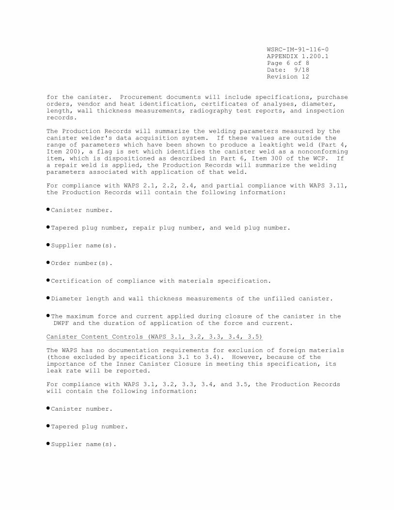
WSRC-IM-91-116-0
APPENDIX 1.200.1
Page 6 of 8
Date: 9/18
Revision 12
for the canister. Procurement documents will include specifications, purchase
orders, vendor and heat identification, certificates of analyses, diameter,
length, wall thickness measurements, radiography test reports, and inspection
records.
The Production Records will summarize the welding parameters measured by the
canister welder's data acquisition system. If these values are outside the
range of parameters which have been shown to produce a leaktight weld (Part 4,
Item 200), a flag is set which identifies the canister weld as a nonconforming
item, which is dispositioned as described in Part 6, Item 300 of the WCP. If
a repair weld is applied, the Production Records will summarize the welding
parameters associated with application of that weld.
For compliance with WAPS 2.1, 2.2, 2.4, and partial compliance with WAPS 3.11,
the Production Records will contain the following information:
• Canister number.
• Tapered plug number, repair plug number, and weld plug number.
• Supplier name(s).
• Order number(s).
• Certification of compliance with materials specification.
• Diameter length and wall thickness measurements of the unfilled canister.
• The maximum force and current applied during closure of the canister in the DWPF and the duration of application of the force and current.
Canister Content Controls (WAPS 3.1, 3.2, 3.3, 3.4, 3.5)
The WAPS has no documentation requirements for exclusion of foreign materials
(those excluded by specifications 3.1 to 3.4). However, because of the
importance of the Inner Canister Closure in meeting this specification, its
leak rate will be reported.
For compliance with WAPS 3.1, 3.2, 3.3, 3.4, and 3.5, the Production Records
will contain the following information:
• Canister number.
• Tapered plug number.
• Supplier name(s).

WSRC-IM-91-116-0
APPENDIX 1.200.1
Page 7 of 8
Date: 9/18
Revision 12
• Order number(s).
• Certification that all in-process inspections were performed to ensure the exclusion of foreign materials.
• Leak rate of the inner canister closure (ICC).
• Identification of an ICC as a repair ICC, and the parameters associated with it (e.g., leak rate, repair plug number).
Canister Fill Level (WAPS 3.6)
The WAPS require that the DWPF report, in the Production Records, the fill
level within each canister. This information will be obtained from the
infrared level detection system.
The Production Records for each canister which has less than 80% fill height
will clearly indicate this, but the DWPF proposes to take no further action
(i.e., attempting to perform another pour into the canister) if the 80% fill
height is not achieved.
The form for this record contains:
• The canister number.
• The glass height determined from the infrared level detection system.
• The date the canister was filled.
References
1. U.S. Department of Energy Memorandum of Agreement for Acceptance of
Department of Energy Spent Nuclear Fuel and High-Level Radioactive Waste,
between the Assistant Secretary for Environmental Management (EM), and the
Director, Office of Civilian Radioactive Waste Management (RW), Washington,
D.C.
2. J. W. Ray, “Defense Waste Processing Facility (DWPF) Path Forward on DOE-
EM Waste Acceptance Product Specifications (WAPS) 2015 Index Year for
Radionuclide Reporting,” SRR-WSE-2018-00020, Revision 0, Savannah River Site,
Aiken, SC (2018).
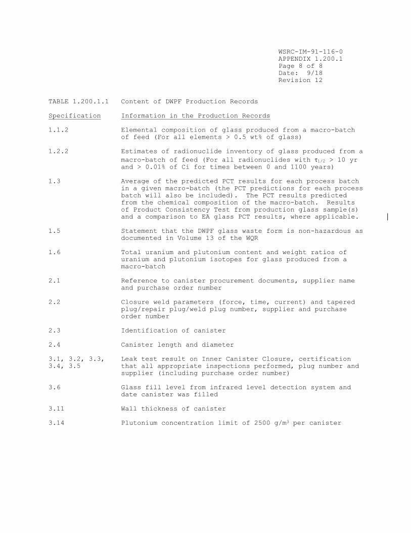
WSRC-IM-91-116-0
APPENDIX 1.200.1
Page 8 of 8
Date: 9/18
Revision 12
TABLE 1.200.1.1 Content of DWPF Production Records
Specification Information in the Production Records
1.1.2 Elemental composition of glass produced from a macro-batch
of feed (For all elements > 0.5 wt% of glass)
1.2.2 Estimates of radionuclide inventory of glass produced from a
macro-batch of feed (For all radionuclides with 1/2 > 10 yr and > 0.01% of Ci for times between 0 and 1100 years)
1.3 Average of the predicted PCT results for each process batch
in a given macro-batch (the PCT predictions for each process
batch will also be included). The PCT results predicted
from the chemical composition of the macro-batch. Results
of Product Consistency Test from production glass sample(s)
and a comparison to EA glass PCT results, where applicable.
1.5 Statement that the DWPF glass waste form is non-hazardous as
documented in Volume 13 of the WQR
1.6 Total uranium and plutonium content and weight ratios of
uranium and plutonium isotopes for glass produced from a
macro-batch
2.1 Reference to canister procurement documents, supplier name
and purchase order number
2.2 Closure weld parameters (force, time, current) and tapered
plug/repair plug/weld plug number, supplier and purchase
order number
2.3 Identification of canister
2.4 Canister length and diameter
3.1, 3.2, 3.3, Leak test result on Inner Canister Closure, certification
3.4, 3.5 that all appropriate inspections performed, plug number and
supplier (including purchase order number)
3.6 Glass fill level from infrared level detection system and
date canister was filled
3.11 Wall thickness of canister
3.14 Plutonium concentration limit of 2500 g/m3 per canister

WSRC-IM-91-116-0
APPENDIX 1.200.2
Page 1 of 6
Date: 3/06
Revision 8
DESCRIPTION
OF THE STORAGE AND SHIPPING RECORDS FOR
DWPF CANISTERED WASTE FORMS

WSRC-IM-91-116-0
APPENDIX 1.200.2
Page 2 of 6
Date: 3/06
Revision 8
APPENDIX 1.200.2 Description of the DWPF Storage and Shipping Records
INTRODUCTION
The Department of Energy's Office of Environmental Management (EM) has
established specifications the DWPF product must meet. These Waste Acceptance
Product Specifications (WAPS) require that the DWPF provide evidence of
compliance with the WAPS during production. This evidence is to be documented
and sent to the Office of Civilian Radioactive Waste Management (RW) in the
form of Storage and Shipping Records for DWPF canistered waste forms. In this
Appendix the content of the Storage and Shipping Records is detailed, based on
the WAPS and the Waste Acceptance Process activities described in the DWPF
Waste Form Compliance Plan.
CONTENT
The Storage and Shipping Records summarize the storage history of DWPF
canistered waste form after production and contain information necessary for
shipment. The DWPF will provide the Storage and Shipping Records to the
Office of Civilian Radioactive Waste Management at time of shipment of the
canistered waste forms. Because it is unlikely that this will occur before
the year 2015, a shipping facility to accomplish many of the actions described
in this Appendix has not yet been designed. Such a facility will undoubtedly
contain a smear test station, equipment to measure the weight and dimensions
of canistered waste forms, instruments to measure the dose rate from the
canistered waste form, and other equipment necessary to satisfy whatever
specifications are in existence at that time.
The information to be reported is summarized in Table 1.200.2.1. Any actions
to be taken based on the information are also identified.
Identification and Labeling
The Storage and Shipping Records will identify particular canisters by the
code on the label affixed to the canister. This code, unique to each
canister, will be the key to tracing the records for each canistered waste
form.
Timing
The DWPF will provide the original Storage and Shipping Records (or copies in
accordance with requirements for QA records packages) to RW at the time of
acceptance of the canistered waste forms. Copies of the Storage and Shipping
Records will be made available for RW review and approval at least 12 months
prior to the scheduled acceptance. RW should review the Storage and Shipping
Records for completeness and accuracy in accordance with appropriate QA
requirements. The Storage and Shipping Records will be treated by the DWPF as
lifetime quality records.
WSRC-IM-91-116-0
APPENDIX 1.200.2
Page 3 of 6
Date: 3/06
Revision 8
Phase Stability
The Storage and Shipping Record for each canistered waste form will certify
that the maximum waste glass temperature experienced during storage of each
canistered waste form is at least 100°C below the transition temperature. The
Storage and Shipping Record for each canistered waste form will also certify
that after initial cooldown, no unusual events occurred which would cause the
maximum temperature of the canistered waste form to exceed the specified
temperature (400°C), during handling and storage at the DWPF. After filling,
the canister will be held in the Melt Cell until it cools below 100°C (thus,
unless some thermal excursion occurs, the canister temperature must be less
than 100°C at time of shipment). After the canister is transferred to the
Canister Decontamination Cell, it can exceed the specified temperature (400°C)
in only two ways:
The heat generation rate of the glass is too high, so that heat buildup
occurs during storage. The heat generation rate of the glass will be
calculated from the radionuclide inventory (see below). Calculations using
the design of the interim Glass Waste Storage Buildings (GWSBs) and the
projected heat generation rates will be used to show that the specified
temperature (400°C) will not be exceeded. Although detailed calculations have
not yet been performed, they are expected to show that canisters of waste
glass which comply with the heat generation rate specification also comply
with this specification. These detailed calculations will be included in the
Waste Form Qualification Report.
An unexpected high temperature event, such as a fire in the interim GWSBs,
has exposed the glass to high temperatures. Temperature sensing devices in
the GWSBs may be used to evaluate the impact of such an event on the
canistered waste forms stored in the GWSBs. If the sensors are
damaged/inoperable or the temperature excursion data are not available, other
means, such as calculations will be used to assess the impact on the
temperature of the glass.
If a high temperature is detected in the GWSBs or a high temperature is
calculated, a written record will be generated which includes:
Date(s) and duration of excursion.
The maximum temperature reached.
The canisters contained in the GWSBs during the excursion.
A statement that these canisters are potentially nonconforming items.
This record will be included in the Storage and Shipping Records.
If such a condition occurs, an investigation of the incident will be
documented, and the canisters will be dispositioned as described in Part 6,
Item 300 of the WCP. The disposition will also be included in the Storage and
Shipping Records.
Removal of Canister Contamination
The WAPS require that the DWPF provide evidence of removal of contamination in
the Storage and Shipping Records. The DWPF will report the smear test results

WSRC-IM-91-116-0
APPENDIX 1.200.2
Page 4 of 6
Date: 3/06
Revision 8
for each canister. If the level of contamination exceeds 2,200 alpha dpm/100
cm , or 22,000 beta or gamma dpm/100 cm , the canister will be decontaminated
again before it is placed in the cask. In this case, the results of a
confirmatory smear test will also be reported.
If the canister contamination level cannot be brought down to the DOE
specified values discussed above, then the canister will be identified as a
nonconforming item, and dispositioned according to the procedure outlined in
Part 6, Item 300 of the Waste Form Compliance Plan.
The record will include the results of smear tests from the shipping facility,
and identification of tester(s).
Heat Generation Rate
The WAPS require that the DWPF report, in the Storage and Shipping Records,
the heat generation rate for the canistered waste forms at year of shipment.
The heat generation rate will be calculated from the radionuclide content of
the glass shortly before shipment of the canistered waste forms, using
standard values of the thermal output per unit activity for each
radionuclide. The radionuclides which will be included in performing this
calculation will be those which significantly contribute to the heat
generation. The radionuclides to be reported to the repository as part of the
radionuclide inventory, as well as radionuclides analyzed for process control
purposes in the DWPF will be considered.
Gamma and Neutron Dose Rates
The WAPS require that the DWPF report, in the Storage and Shipping Records,
the gamma and neutron dose rates for the canistered waste forms, at time of
shipment. At time of shipment, these will be measured in the DWPF shipping
facility.
If the measured dose rates exceed 10 rem/hr surface gamma dose rate, or 10
rem/hr neutron dose rate, then the canister will be identified as a
nonconforming item, and dispositioned according to the procedure outlined in
Part 6, Item 300 of the Waste Form Compliance Plan.
Weight and Overall Dimensions
The WAPS require that the DWPF report the weight of each glass-filled canister
in the Storage and Shipping Records. The DWPF must also certify that the
canister will fit without forcing into a right circular cylinder. The weight
will be measured prior to shipment, and the weight and the estimated error of
the measurement reported. Methods to certify the canister will fit without
forcing into a cask have not yet been developed but will probably involve use
of a ring gauge.
If the canister weight exceeds the specified amount or the canister cannot fit
in the specified cylinder, then the canistered waste form will be identified
as a nonconforming item, and dispositioned according to the procedure outlined
in Part 6, Item 300 of the Waste Form Compliance Plan.

WSRC-IM-91-116-0
APPENDIX 1.200.2
Page 5 of 6
Date: 3/06
Revision 8
References
1. U.S. Department of Energy Memorandum of Agreement for Acceptance of Department of Energy Spent Nuclear Fuel and High-Level Radioactive Waste, between the Assistant Secretary for Environmental Management (EM), and the
Director, Office of Civilian Radioactive Waste Management (RW), Washington,
D.C.
2. Integrated Data Base for 1990: Spent Fuel and Radioactive Waste Inventories, Projections, and Characteristics, USDOE Report RW-0006, Revision 6.

WSRC-IM-91-116-0
APPENDIX 1.200.2
Page 6 of 6
Date: 3/06
Revision 8
TABLE 1.200.2.1 Content of DWPF Storage and Shipping Records
Specification Information in the Storage and Shipping Records
1.4 Certification that the maximum waste form
temperature has always been below 400°C
3.7 Results of smear tests performed in the shipping facility
3.8.2 Heat generation rate
3.9.2 Gamma and neutron dose rates
3.11 Weight of filled canister, and estimated error
3.11 Certify that canister fits without forcing into the
specified cylinder

WSRC-IM-91-116-0
APPENDIX 1.200.3
Page 1 of 7
Date: 3/06
Revision 8
SUMMARY
DWPF QUALIFICATION RUNS ACTIVITIES

WSRC-IM-91-116-0
APPENDIX 1.200.3
Page 2 of 7
Date: 3/06
Revision 8
APPENDIX 1.200.3 Summary of DWPF Qualification Runs Activities Relevant to
the Waste Acceptance Process
OBJECTIVES
The objectives of the DWPF Startup Test Program are to accomplish the
following:
To demonstrate the overall functionality of the DWPF process and its
auxiliary facilities using synthetic feeds so that operating conditions and
procedural requirements can be adequately demonstrated prior to beginning
radioactive operations.
To perform tests required by the Waste Form Compliance Plan (WCP) which
demonstrate that the DWPF process and product control are adequate to satisfy
the requirements of the Waste Acceptance Product Specifications (WAPS).
A major portion of the Startup Test Program deals with production of simulated
canistered waste forms in prototypic manner, to demonstrate, in particular,
control of the vitrification process. The campaigns in the facility during
which this will be accomplished are called the Qualification Runs. The
activities which will be performed as part of the Qualification Runs are
described in the Appendix. This appendix does not address those tests that
will be performed during initial Radioactive Operations (e.g., reporting of
radionuclide inventory and smear testing). These tests are discussed in the
specific sections of the Waste Form Compliance Plan. The results of all
testing will be reported in the Waste Form Qualification Report.
QUALIFICATION RUNS
The sections below describe specific tests which will be performed during the
Startup Test Program for inclusion in the Waste Form Qualification Report to
demonstrate compliance with the WAPS. In addition, most of the routine
measurements and procedures which will be performed during radioactive
operations and included in the Production Records will also be performed
during this time.
The initial charge to the melter will be glass frit specially formulated for
melter startup. After building the melter level to the operating level and
achieving stable melter operation, the Qualification Runs will begin. These
campaigns will be sludge/precipitate runs with (in order of performance):
a) a nonradioactive doped composition to simulate variations around the
composite feed (approximately 7 canisters containing 26,000 lbs of glass
produced, corresponding to almost 2 melter turnovers),
b) a nonradioactive low viscosity (high iron) composition to simulate another
extreme change in feed composition (approximately 20 canisters containing
75,000 pounds of glass produced, corresponding to 5 melter turnovers), and

WSRC-IM-91-116-0
APPENDIX 1.200.3
Page 3 of 7
Date: 3/06
Revision 8
c) a nonradioactive high viscosity (high aluminum) composition to simulate an
extreme change in feed composition (approximately 20 canisters containing
75,000 pounds of glass produced, corresponding to 5 melter turnovers),
d) a nonradioactive composite feed to simulate return to standard operation
from high viscosity (approximately 10 canisters containing 37,000 pounds of
glass produced, corresponding to 2.5 melter turnovers).
To obtain glass samples for characterization, approximately twenty-one glass
filled canisters (three from the beginning and three from the end of each
campaign, except WP-17 which will have three from the beginning only) will be
sliced into 4 horizontal sections using a band saw. One of the slices will be
made at the approximate height corresponding to the level of the glass in the
canister when the glass pour stream sample was taken. The remaining glass
filled canisters will have a 12” wide section of the canister wall removed
using arc-air cutting.
Chemical Composition Projections (Specification 1.1.1)
Cooldown profiles for the canisters obtained during pilot-scale testing will
be verified during Qualification Runs under typical production conditions.
Special instrumented canisters will be designed and procured to perform these
tests. The temperature profiles will then be combined with expected heat
generation from radioactive decay to demonstrate that the glass product will
comply with the WAPS.
There are no specific acceptance requirements for this testing; however, the
objective discussed above must be met.
Chemical Composition During Production (Specification 1.1.2)
The DWPF will demonstrate, during Qualification Runs, its strategy for
reporting the chemical composition. This will be accomplished by the
following objectives:
Confirm the compliance strategy for predicting the glass product
composition from the macro-batch chemical composition based on process batch
analyses. Compare the chemical composition of Slurry Mix Evaporator (SME)
samples and Melter Feed Tank (MFT) samples to the glass samples taken from
sectioned canisters, those with the wall removed, and those taken from the
pour stream.
Provide an estimate of the error of the composition.
Determine crystalline content (type and amount), if any, in the glass
samples taken from the canisters.
There are no specific acceptance requirements for this testing; however, the
above objectives must be met
Product Consistency (Specification 1.3)
The DWPF must demonstrate that it can consistently produce a glass product
that meets the Product Consistency Specification, WAPS 1.3. This will involve
operating the melter with a range of feed compositions with various
rheological properties (as discussed earlier) and using the Glass Product
Control Program (GPCP) to control the glass composition. The GPCP states that
WSRC-IM-91-116-0
APPENDIX 1.200.3
Page 4 of 7
Date: 3/06
Revision 8
no material can be transferred from the Slurry Mix Evaporator to the Melter
Feed Tank until it is determined to be acceptable (see Part 3, Item 500). As
discussed earlier glass samples will be taken from sectioned and wall removal
canisters for analysis. The demonstration of product consistency includes the
following objectives:
Demonstrate that DWPF can obtain glass pour stream samples during
Qualification Runs.
Verify that the glass pour stream sample is representative of canister
contents. The objective is to show that both the chemical composition results
and the PCT results are the same within the applicable uncertainty.
Verify canister glass homogeneity by demonstrating that the results of the
analyses of glass samples taken from the canisters do not indicate that the
position of the glass sample is a significant source of variance.
Demonstrate the effectiveness of the Glass Product Control Program by
verifying that the PCT results (Na, Li, B) of all the glass samples analyzed
are at least 2 standard deviations below the mean PCT results of the EA glass
(compliance with WAPS 1.3). The acceptability of each individual glass sample
will be determined using the standard deviation of the PCT for that glass
sample. The acceptability of the collection of glass samples from each melter
run will be determined using a standard deviation that includes all sources of
composition and PCT variation.
Compare predicted Product Consistency Test results from the Product
Composition Control System (PCCS) to actual PCT results from the glass samples
taken from the last three sectioned canisters for first three melter campaigns
to validate the Product Composition Control System’s ability to determine the
acceptability of melter feed material. The objective is to show that the mean
predicted PCT results from the PCCS and the mean results for actual glass
samples from the sectioned canisters, over each melter run, are not different
at the 5% significance level.
Confirm the compliance strategy and determine the error for reporting the
glass PCT results from the predicted PCT results from each process batch over
the macro-batch. For each melter run, compare the predicted PCT results of
Slurry Mix Evaporator (SME) samples to the PCT results of the glass samples
taken from sectioned canisters, those with the wall removed, and those taken
from the pour stream. The goal of this comparison is to show that the results
are within 30% of each other. A goal of 30% was set for Qualification Runs
because the DWPF will only be processing a few process batches (3-5) during
each melter run. Thus, this difference is much larger than expected during
Radioactive Operations. A secondary objective is to try to establish the
mixing behavior of the melter.
The only specific acceptance requirement for this testing is that the PCT
results (Na, Li, B) of all the glass samples analyzed be at least 2 standard
deviations below the mean PCT results of the EA glass (compliance with WAPS
1.3). In addition, all of the above objectives must be met.
Chemical and Phase Stability (Specification 1.4)
Calculations will be performed to determine if the canistered waste form can
ever exceed 400°C even under upset conditions. The Glass Waste Storage


WSRC-IM-91-116-0
APPENDIX 1.200.3
Page 6 of 7
Date: 3/06
Revision 8
dewpoint measurements and mass spectrometric data must indicate no
detectable foreign materials
Fill Height (Specification 3.6)
Confirmation of an operable level detection system is required to demonstrate
control of the fill level in the canister (desired minimum fill is the height
corresponding to 80% of the free volume of the canister). The objectives for
compliance with this specification are as follows:
Demonstrate that the canister fill height can be monitored and controlled
using the infrared level detection system.
The acceptance requirement for this testing is that the glass fill level can
be monitored so that the canister can be filled to a height equivalent to at
least 80% (by volume).
Canister Decontamination (Specification 3.7)
The DWPF must specify in the Storage and Shipping Records that external
radioactive contamination on the canistered waste forms is below the limits
specified by the WAPS. The method of decontamination of the canistered waste
forms must be demonstrated during the Qualification Runs. This will be
accomplished as follows:
Visually examine selected canisters and evaluate whether the heat tint has
been removed.
Demonstrate remote glass removal by ensuring that the needle gun can reach
the outside surface of the canister except the bottom. There is no identified
method for glass adhesion to the canister bottom.
Evaluate canister damage using the needle gun. The needle gun should not
cause gouges or dents that are greater the 1/32” deep.
There are no specific acceptance requirements for this testing; however, the
above objectives must be met.
Canister Dimensions (Specifications 2.4 and 3.11)
The DWPF must demonstrate that controlling the as-purchased canister
dimensions will ensure that the canistered waste forms comply with the WAPS.
This will be accomplished with the following objectives:
Verify that canister processing does not cause damage to the canister which
could affect its ability to comply with the WAPS.
Confirm that canister glass filling has no significant effect on canister
dimensions and that the final canister dimensions (including weight) comply
with the WAPS. This includes ensuring that the canister stands upright
without support on a flat horizontal surface.

WSRC-IM-91-116-0
APPENDIX 1.200.3
Page 7 of 7
Date: 3/06
Revision 8
The acceptance requirement for this testing is that the canister dimensions
must meet the WAPS after filling as stated below:
canister length - 3.000 m (+0.005 m, -0.20 m)
canister diameter - 61 cm (+1.5 cm, -1.0 cm)
canistered waste form weight - less than or equal to 2500 kg
overall dimensions - the canistered waste form must fit into a right
circular cylinder, 64.0 cm in diameter and 3.01 m in length
The canister must also stand upright without support on a flat
horizontal surface.
Reporting - Production Records
The WAPS require reporting of production data in the Production Records.
During Qualification Runs, the DWPF will confirm that the DWPF is capable of
collecting the necessary information to produce the Production Records as
required by the WAPS. This includes using the operating procedures and
administrative controls expected to be used during Radioactive Operations.
There is no specific acceptance requirement; however, the objective discussed
above must be met.

WSRC-IM-91-116-0 Rev. 12
Page 1 of 3

WSRC-IM-91-116-0 Rev. 12
Page 2 of 3

WSRC-IM-91-116-0 Rev. 12
Page 3 of 3