wrexham arts hub, wrexham - structural engineering stage …€¦ · wrexham arts hub, wrexham...
TRANSCRIPT

Wrexham Arts Hub, Wrexham
Structural Engineering Stage 3 Report
November 2015

Contents
1. Introduction ............................................................................................................................................................................................................................... 1
2. Structural Design Philosophy ......................................................................................................................................................................................... 2
2.1. Introduction .................................................................................................................................................................................................................. 2
2.2. Existing Structure ...................................................................................................................................................................................................... 2
2.3. South Elevation and Demolition of Mezzanine Structure ..................................................................................................................... 2
2.4. East Elevation, Removal of Floor Units and Cuts through Floor Units ............................................................................................ 3
2.5. Provision of Bridge over New Voids................................................................................................................................................................... 4
2.6. Lift Tower Viewing Platform (Optional Future Enhancement) ........................................................................................................... 4
2.7. Future Work – Detailed and Final Design Stage.......................................................................................................................................... 4
2.8. Existing Structural Defects (Outside Scope of Report) ........................................................................................................................... 5
3. Loading (Actions) .................................................................................................................................................................................................................. 6
3.1. Lateral Loading ........................................................................................................................................................................................................... 6
3.2. Gravity Loading ........................................................................................................................................................................................................... 6
4. Design Specifications .......................................................................................................................................................................................................... 6
4.1. Deflections ..................................................................................................................................................................................................................... 6
4.2. Tolerances ..................................................................................................................................................................................................................... 6
5. CDM – Significant Residual Hazards to Health and Safety ................................................................................................................................7
6. Appendices ...............................................................................................................................................................................................................................7

1
1. Introduction Civic Engineers were appointed to prepare a structural design for the proposed redevelopment of the Wrexham People’s Market in Wrexham. The existing building use of Wrexham People’s Market is of market stalls at ground level and 4 split-level storeys of car parking above.
The site is located approximately 0.5km from the town centre. The address is Peoples Market Multi Storey Car Park, Wrexham, LL13 8BG.
Figure 1: Location Plan
The project architects are Featherstone Young, structural engineers are Civic Engineers and building services engineers are Michael Popper Associates.
The proposals for the redevelopment of the Wrexham People’s Market is to incorporate an art and cultural centre for Oriel Wrexham and will require several structural interventions to the existing structure including: forming of voids on the south elevation and demolition of the mezzanine, forming voids on the east elevation and removing floor units at first floor level, and forming slots through second floor slabs.
Other structural works are noted but are beyond the scope of this report. A proposed viewing platform is highlighted as a possible future addition whilst structural repairs are noted but are to be included in a separate maintenance budget.
Figure 2: Site Plan

2
2. Structural Design Philosophy
2.1. Introduction
The required structural alterations and additions to the existing building structure are outlined in this report. The existing structure is summarised, then the proposed alterations and the structural interventions required are defined.
The structural arrangement of the existing People’s Market building is summarised below.
2.2. Existing Structure
The People’s Market, completed in 1990, consists of a Market Hall at ground floor level with four stories of split level car parking provided over. Supplementary shop units are provided in two wings extending west towards Chester Street from the north and south sides of the Market Hall.
The structure comprises an insitu reinforced concrete frame and four vertical shear cores located at the corners of the car parking structure. Vehicular access to the upper level car parking is provided via a concrete ramp from Market Street entering on the southern elevation of the structure. Internal floors comprise precast, prestressed reinforced concrete ‘double Tee’ and ‘single Tee’ units with an insitu reinforced concrete topping. A mezzanine level is located at ground floor at the south end of the Market Hall. The mezzanine structure is steel beams and columns with precast reinforced concrete planks spanning between beams. The building envelope is cavity wall construction from ground to first floor with external brickwork cladding and internal blockwork walls. From first floor upwards the building envelope is single leaf brick and decorative blockwork cladding with openings in the elevations infilled with metal grilles at parking levels and windows to stores, circulation cores and the market hall at ground floor level.
Our understanding of the existing structure is based on the information available to date, which primarily comprises a structural report by Bingham Rawlings Partnership Ltd (BRP) dated June 2015, and a Life-care Plan on behalf of Wrexham County Borough Council. It has been discovered that a near holistic set of drawings do exist for the structure, and progress is being made into locating and obtaining the as-built engineering information. Civic Engineers have carried out a site walkover inspection to verify and supplement the information currently available. This understanding of the existing structure is summarised on Civic Engineers drawings (SK)007 – (SK)010 appended to this report.
The three primary structural interventions are described below:
2.3. South Elevation and Demolition of Mezzanine Structure
The proposals for the south elevation include the removal of the mezzanine structure that currently accommodates plant for the ventilation and heating of the Market Hall. In addition, the brickwork façade directly adjacent to the mezzanine is to be removed.
The extent and exact configuration of the mezzanine structure is subject to further survey. Visual inspection suggests the mezzanine structure to be independent of the primary structure of the building and could therefore be removed with no influence on the structural stability of the main structure. The proposals are for the plant equipment to be rehoused in a newly formed plant room space at ground floor level.
The brickwork façade adjacent to the mezzanine on the south elevation is to be removed. To avoid the requirement of a new lintel, the brickwork is to be removed up to the level at which the brickwork above is currently supported – refer to Figure 4.
Figure 3: First Floor Plan showing approximate location and arrangement of mezzanine structure below
3
Figure 4: Part South Elevation indicating mezzanine and primary structure
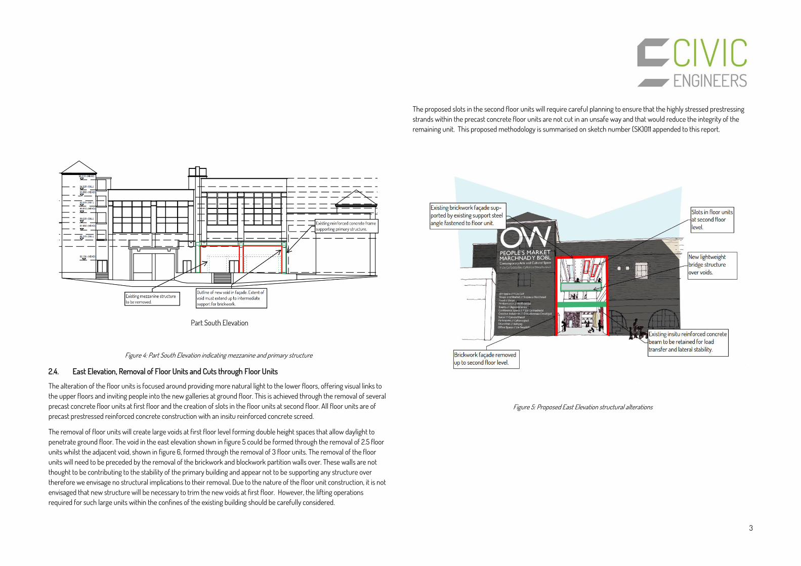
2.4. East Elevation, Removal of Floor Units and Cuts through Floor Units
The alteration of the floor units is focused around providing more natural light to the lower floors, offering visual links to the upper floors and inviting people into the new galleries at ground floor. This is achieved through the removal of several precast concrete floor units at first floor and the creation of slots in the floor units at second floor. All floor units are of precast prestressed reinforced concrete construction with an insitu reinforced concrete screed.
The removal of floor units will create large voids at first floor level forming double height spaces that allow daylight to penetrate ground floor. The void in the east elevation shown in figure 5 could be formed through the removal of 2.5 floor units whilst the adjacent void, shown in figure 6, formed through the removal of 3 floor units. The removal of the floor units will need to be preceded by the removal of the brickwork and blockwork partition walls over. These walls are not thought to be contributing to the stability of the primary building and appear not to be supporting any structure over therefore we envisage no structural implications to their removal. Due to the nature of the floor unit construction, it is not envisaged that new structure will be necessary to trim the new voids at first floor. However, the lifting operations required for such large units within the confines of the existing building should be carefully considered.
The proposed slots in the second floor units will require careful planning to ensure that the highly stressed prestressing strands within the precast concrete floor units are not cut in an unsafe way and that would reduce the integrity of the remaining unit. This proposed methodology is summarised on sketch number (SK)011 appended to this report.
Figure 5: Proposed East Elevation structural alterations

4
2.5. Provision of Bridge over New Voids
The new first floor voids will create a segregation of the floor space and limit horizontal circulation within the building. This is addressed with the addition of a new lightweight bridge structures spanning over the new voids. The new bridge will span approximately 7.2 m across the void and will be supported off the adjacent existing precast floor units.
Figure 6: Proposed First Floor Plan Indicating Location of New Bridge Structures
Assessment of the existing precast floor units will be carried out in the next stage to determine the support details for the bridge bearings. Should localised strengthening be required then trimming steelwork running parallel to the precast floor units could be provided supplement the precast units in supporting the bridge bearings.
A lightweight steel bridge is proposed that will be designed for crowd loading, should the bridge be used as a viewing platform of the exhibition space below, as well as dynamic loading due to footfall associated with the circulation route created.
2.6. Lift Tower Viewing Platform (Optional Future Enhancement)
A viewing platform is proposed to be constructed in the north-east shear/lift core to provide a view point of the city for visitors. The proposed platform is a cantilevered steel frame, anchored back to the existing reinforced concrete frame.
Access to the viewing platform will be provided by a continuous ramp running through the lift/plant room and independent to the existing floor levels. New openings will be required within the existing reinforced concrete walls forming the lift/plant room to allow access onto the new viewing platform.
2.7. Future Work – Detailed and Final Design Stage
Existing as-built engineering drawings are believed to be held by Wrexham County Council and progress is being made to obtain these for reference. The information will be reviewed in detail and will help inform a strategy for intrusive works that will further the understanding of the existing structure. The structural alterations outlined above are based on the information gathered thus far and a walkover survey. Intrusive investigation works are required to prove any assumptions and substantiate our understanding of the existing structure in the next stage of design. A drainage survey will also be required in the next design stage.
Figure 7: Proposed Lift Tower Platform

5
2.8. Existing Structural Defects (Outside Scope of Report)
A review of the structural report by Bingham Rawlings Partnership (BRP) Limited dated March 2015 highlight a number of repair items associated with the existing structure. The items in the table below are outside the scope of this report and the works it describes. The items are noted below only as acknowledgement of their existence and are to be included in a separate maintenance budget.
Defect Location Recommended Remedial Action
Displaced Brickwork Holt Street Elevation (North Face) Re-bed in mortar
Sheared Edge of Shelf Support Car Park Level 3 Provide propriety concrete repair, i.e, Sika or similar approved.
Original Lifting Bracket Car Park Level 3 Coat exposed stub sections of rebar with rust inhibitor
Exposed Tendons at end of Tee Beam Car Park Level 3 & 3A Coat with a bitumastic paint
Beam/Wall Interface Car Park Level 3 Expose defect for further examination
Wall Interface with End Tee Beam (Spalling of Concrete)
Car Park Level 1 & 1A Clean up joint for further inspection
Defective Gulley and Concrete Shelf Support
Car Park Level 1 & 1A Repair and replace drainage gulley from Level 2A roof car park
Clean up concrete shelf support and carefully remove spalled concrete to shelf. Provide temporary support to underside of tee beam and provide proprietary concrete repair by Sika or similar approved.

6
3. Loading (Actions) The building structure Stage 3 design has been developed to suit the following loads (actions):
Lateral loads as described in Section 3.1 Self-weight of primary structure and superimposed dead loads as described in Section 3.2 Imposed loads as described in Section 3.2
3.1. Lateral Loading No change to the applied lateral loading of the building is envisaged with the proposed structural alterations described in this report.
3.2. Gravity Loading A change in use of the building results in a change in applied loading on the existing structure. New super-imposed dead loads and occupancy loads appropriate to the new exhibition space use of the building have been reviewed against previous occupancy loads for car parking.
The following minimum imposed loads are applicable to the building superstructure and have been used to inform the Stage 3 design:
Type of Use Uniformly distributed load kN/m2
Concentrated load kN
Existing – Car Park 2.5 9.0 Proposed – Exhibition Space 4.0 4.5
The above minimum imposed design loads are in accordance with the following guides:
British Standard 6399 Loading for buildings – Part 1: Code of practice for dead and imposed loads
Superimposed loads are not available at this stage. Floor build-up, finishes and services are yet to be finalised therefore superimposed load of 1.5kN/m2 has been assumed.
4. Design Specifications
4.1. Deflections Overall deflection limits and other serviceability performance limits are to be accordance with current recognised good practise, to include limits defined by relevant applicable Eurocodes and British Standards. The following limiting criteria are to be applied:
Criteria Limiting Value Vertical deflection – under imposed load Span/360 Total vertical deflection Span/250 Sway of each storey of multi storey columns Span/300 Limiting crack width – thermal and shrinkage movement 0.3mm
The design of the substructure is to be in accordance with current recognised good practice.
4.2. Tolerances Tolerances will be in accordance with the following current recognised good practice, guidance documents and regulations:
BS 5606 - Guide to Accuracy in building BS EN 13670 – Execution of concrete structures National Structural Concrete Specification for Building Structures National Structural Steelwork Specification for Building Structures

7
5. CDM – Significant Residual Hazards to Health and Safety
The following is a summary of the Significant Residual Hazards we have identified in relation to the construction works at Wrexham People’s Market. All construction activities involve risk and it is not possible to eliminate all hazards in the design. We consider buildability and maintenance of a design assuming that the Contractor will use methods of construction and procedures that are generally accepted as safe within the industry. We do not dictate what these methods and procedures must be, as they have to be chosen by the Contractor in relation to his management, available skills and abilities. We aim to identify areas where our engineering design may require special consideration as to how it is built or maintained. This summary is not intended to be comprehensive, but aims to highlight the significant hazards associated with this project, which it has not been possible to eliminate during the design process.
Residual Hazard Response in Design Action by Contractor
Risk of cutting through prestressing tendons within existing precast concrete floor units during alterations
Restrictions on extents and locations of cutting of existing prestressed units placed on the design proposals
Provide method statement for undertaking cutting works to existing prestressed units
Removal of existing large precast concrete slab units with confines of existing building to form new openings at first floor level
Number and extent of slab units to be removed minimised
Provide method statement and lifting plan for removal of existing precast concrete elements
6. Appendices (SK)013 – Proposed Ground Floor Structural Alterations
(SK)014 – Proposed First Floor Structural Alterations – Rev B
(SK)015 – Proposed Second Floor Structural Alterations – Rev B

status
revisions
002
job
address
dwg title
scale date
drawing numberjob reference revision
Refurbishment: Art & Culture Centre
Existing GF Plan1:500 09/15
PEP
Chester St, Wrexham, LL13 8BY
Draft ARCHITECTS
25 Links Yard. Spelman St. London E1 5LXtel 020 7539 3686fax 020 7539 3687
mail@featherstoneyoung .comwww.featherstoneyoung .com
Notes:1. Do not scale from this drawing.2. All dimensions to be checked on site by contractor and such dimensions to be his responsibility.3. Report all drawing errors and omissions to the architect.
A dd.mm.yy RevisionX XXXXX


(The
Cro
ft Pea
ce
El
Gard
en)
Gard
d Hed
d y C
rofft
Sub S
ta
TCB
El S
ub Sta
Cour
tyard
The
S
A
PH
PH
El S
ub Sta
rooflights
rooflights
CAR PARK(level 2A)
CAR PARK(level 2B)
CAR PARK on roof(level 2B)
status
revisions
102
job
address
dwg title
scale date
drawing numberjob reference revision
Refurbishment: Art & Culture Centre
Proposed 2F Plan1:500 09/15
PEP
Chester St, Wrexham, LL13 8BY
For Information ARCHITECTS
25 Links Yard. Spelman St. London E1 5LXtel 020 7539 3686fax 020 7539 3687
mail@featherstoneyoung .comwww.featherstoneyoung .com
Notes:1. Do not scale from this drawing.2. All dimensions to be checked on site by contractor and such dimensions to be his responsibility.3. Report all drawing errors and omissions to the architect.
A dd.mm.yy Revision- 06.11.2015 First Issue
A 25.11.2015 Minor Amendments

8
Prepared by DS
Reviewed by JBr
Issued: 26th November 2015
This report is the copyright of Civic Engineers and is for the sole use of the person/organisation to whom it is addressed. It may not be used or referred to in whole or in part by anyone else without the express agreement of Civic Engineers. Civic Engineers do not accept liability for any loss or damage arising from any unauthorised use of this report. Civic Engineers is a trading name of Civic Engineers Limited (registered number 06824088), which is a limited company registered in England, registered address Carver's Warehouse, 77 Dale Street, Manchester M1 2HG.
© Civic Engineers 2015