world trade center: construction, destruction, and ... web/tenth buchanan... · world trade center:...
TRANSCRIPT
1
World Trade Center: Construction, Destruction, and
Reconstruction
By Arnold Aronowitz, Fellow ASCE
Retired Chief Geotechnical Engineer, The Port Authority of N.Y & N.J
On September 11, 2001, terrorists destroyed the World Trade Center. They crashed
a Boeing 767 into the North Tower at 8:45AM and eighteen minutes later, another Boeing
767 into the South Tower. The towers did not collapse. The North Tower remained
standing for 104 minutes and the South Tower remained standing for 62 minutes before
they collapsed. The structures fell into the World Trade Center’s basement, which had
seventy-foot high walls, which remained standing. As part of the recovery effort new
anchors were installed to support the walls.
INTRODUCTION
The work to construct the World Trade Center’s foundations was an engineering
endeavor that even today is not fully appreciated. This paper will deal mostly, with the
Geotechnical effort associated with its construction. The foundations were designed and
constructed by the Port Authority. John M. Kyle was the Chief Engineer. Martin S. Kapp
(Marty) was the head of the Soils Division (Chief Foundation Engineer). He was later
promoted to Chief Engineer. I was the head of the Soils Division’s Design Section.
The financial, political, and sociological reasons of why and how the World Trade
Center was constructed are fascinating but will not be dealt with in this paper. What will
be discussed are the Geotechnical contributions that resulted in solving engineering and
construction problems and in altering the scope and magnitude of the entire project. The
concepts dealing with innovation, creativity and the research required to accomplish these
tasks will be explored.
2
THE SITE
The Port Authority constructed the World Trade Center on twelve city blocks, very
close to the Hudson River, in downtown Manhattan. Four blocks were in the north south
direction and three bocks were in the east west direction. In colonial times most of the site
was below water. Filling the site with twenty to thirty feet of debris, garbage, ships ballast,
and other materials, raised the ground surface above the water level. Below the fill, twenty
to thirty feet of very soft clays existed on the western side of the site. The bottom of the
clay increased in elevation and gradually disappeared approximately one block east of
West Street, the western boundary of the site. Other soils, found below the fill or clay
soils, generally ranged from silt to sand with different percentage of each in a given
sample. Below these other soils, there was from zero to twenty feet of a very dense
conglomerate of variable permeability that overlaid the Mica Schist rock. The elevation of
the top of rock ranged from fifty to sixty five feet below the Mean High Water elevation in
the Hudson River (MHW). The rock had mica and schist stratifications that were close to
vertical. The rock was also randomly jointed in all directions.
Two blocks from the western boundary, at Greenwich Street, is an IRT transit
tunnel tha t traverses in a north south direction. Beneath the IRT structure existed two
active PATH commuter tunnels. They started in New Jersey and continued in an easterly
direction below the Hudson River to New York. The tunnels continued increasing in
elevation so that they could reach the elevation of the station on the easterly side of the
IRT subway. The PATH trains were on rock at the westerly side of the site, then on soft
clay and then on silt and sand soils, as they continued in an easterly direction.
PLANNING AND CONCEPTUAL DESIGNS
Many schemes were studied to accommodate the square footage required for
potential tenants of the World trade Center. We made cost estimates to construct the
foundations and underground parking garages associated with these schemes. The garages
were estimated to be very costly because the high water table, at the site, required that the

3
garages be constructed with thick concrete base slabs or the utilization of vertical tie down
anchors. The sheeted excavations and dewatering, close to existing structures, through fill,
soft clay and other soils added significantly to the estimated cost. Possible damage to
adjacent streets, utilities, and structures could also have added to that cost.
Port Authority Geotechnical engineers proposed a cost effective alternative. We
proposed to construct a hollow concrete rectangular structure consisting of horizontal cut-
off walls, without a base slab, that would be imbedded into rock. The top of the walls
would be above the water level. A drainage system would be constructed above the rock,
to collect and discharge minor water seepage that would flow into the structure. This
concept eliminated the need for a thick base slab or vertical tie down anchors and
facilitated the placement of footings directly upon the rock. These footings could support
the garages and the other structures. This concept also provided much more revenue
producing space in the proposed seventy-foot deep basement area. Port Authority Planners
adopted this concept. However, they enhanced our proposal by relocating the PATH
Station to the bottom floor of the new enlarged basement area. This final scheme, a
basement with six floors, that extended four blocks in a north-south direction and two
blocks in an east-west direction, provided many geotechnical challenges.
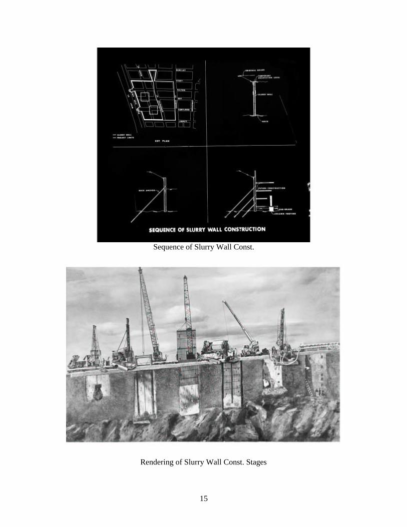
THE SLURRY WALL
The first major challenge was to determine the kind of cut-off wall and how it
should be constructed. Marty proposed that slurry wall panels should be used. He was
instrumental in convincing European contractors along with the only contractor, in New
York, who was able to do the work to submit bids on this unusual type of construction.
The increased competition lowered the cost of the wall. A slurry wall had never been
constructed that was as long and posed as many challenges as the one we proposed to
build.
A wall panel was constructed by excavating a three-foot wide trench approximately
twenty-two feet long that was continuously backfilled with slurry. The slurry was a
mixture of Bentonite clay and water and had the consistency of pea soup. The slurry kept
the walls of the trench from caving in. This process also minimized the movement of the
4
adjacent pavements, utilities and structures including the adjacent IRT tunnel. The wid th
of the trench was sufficiently wide to allow the removal of most obstructions and to utilize
equipment required to chop out the rock socket. After an excavation was completed, a
steel reinforcing cage with inserts for anchors was lowered into the trench. Tremi concrete
was then deposited starting at the bottom of the trench. As the concrete filled the trench, it
pushed the slurry out, forming a reinforced concrete wall.
The entire site was not available when the construction of the wall was started.
Streets had to be kept open. Some utilities had not been relocated and the demolition work
had not been completed. However, since each panel could be constructed independently
from one another, many rigs worked at the same time in different areas of the site, thereby,
expediting the completion of construction.
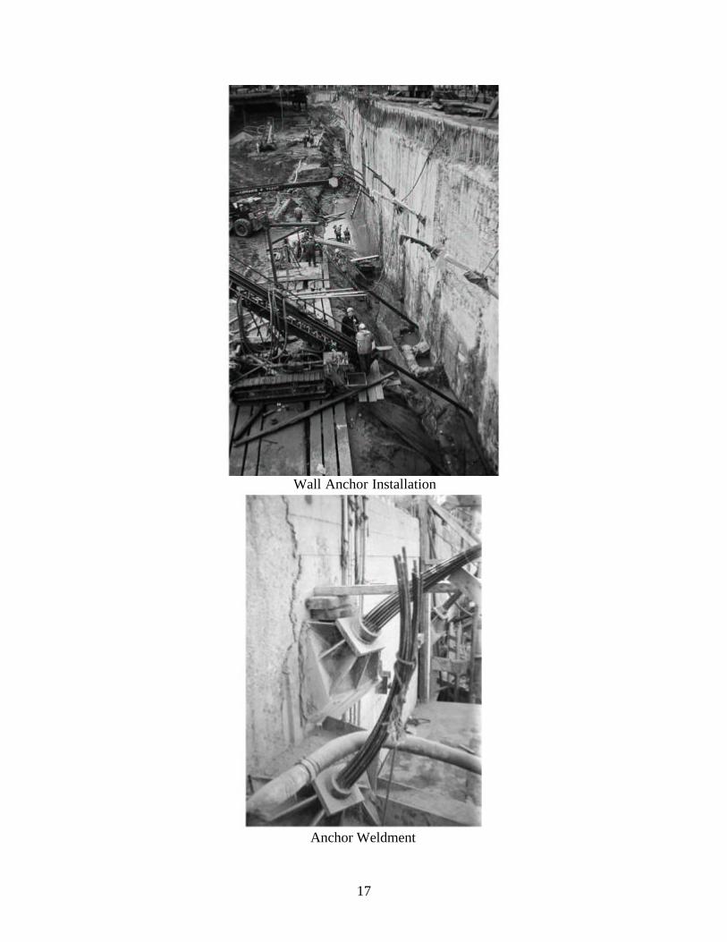
Pre-stressed “tie-back tendons” imbedded into rock with a maximum design capacity of six
hundred thousand pounds were selected to tie back the walls. Four to six rows of
anchors were installed as the soil in front of the wall was removed. The required
number depended on localized site conditions. Some anchors were de-stressed
after anchors at lower elevations were installed. This process was required to
minimize the magnitude of the bending moments that developed in the wall.
Concrete buttresses were installed near the bottom of the wall if the sound rock
elevation was too low for the lowest floor to brace the wall after the rock anchors
were removed. Vertical, “tie-back tendons”, rock anchors were installed, in front
of a buttress to intercept inclined joints in the rock.
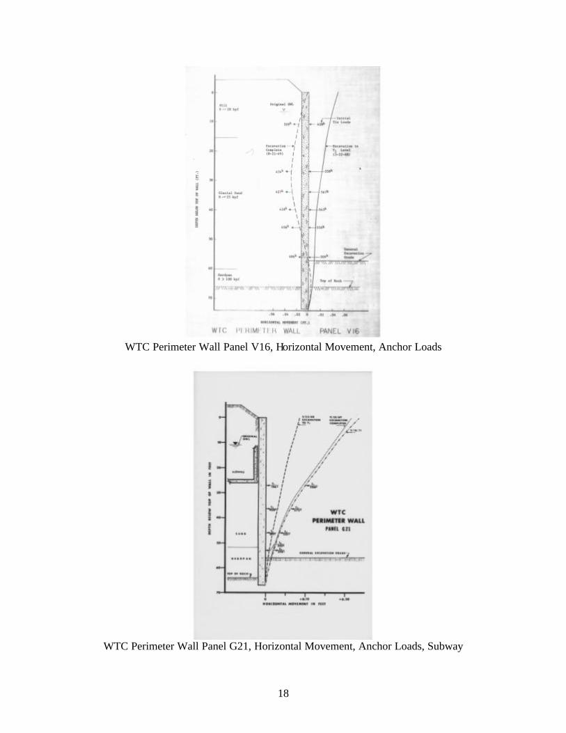
A design procedure was developed by Donald York, Marty’s assistant, to determine the
magnitude of stress in each anchor and the bending moment in the wall at each
stage of excavation. Carlson strain meters and slope inclinometer casings were
installed inside selected slurry wall panels to facilitate the determination of the
bending moments in the wall. Load cells were used to measure anchor loads in test
panels. The measured Tie-Back Loads in all the test panels decreased from their
“final” pre-stressed values. The data obtained from the strain meters, inclinometers
and load cells was used to evaluate the condition of the walls.
The top of a test panel on West Street moved approximately three inches into the soil
behind the wall. The measured Tie-Back Loads decreased as the wall moved away

5
from the excavation. They were approximately equal to the “Elastic” Tie-Back
Loads that were computed from the wall deflections. The wall movement and the
resulting decrease in length of the “tie-back tendons” was most likely due to the
yielding of the twenty-five feet of soft clay (called Organic Silt) behind the wall.
The top of a test panel on Greenwich Street moved approximately three inches away from
the soil behind the excavation. The measured Tie-Back Loads also decreased but
the wall moved toward the excavation. Here the top anchors had to be installed at
greater depths than anchors installed in other streets because the bottom of the IRT
subway was approximately twenty-six feet below the top of the slurry wall. The
panels adjacent to Greenwich Street were temporarily braced at higher elevations,
until the top anchors were installed. The most likely reason that the Tie-Back
Loads decreased was due to “slippage” since the movement of the wall was toward
the excavation. The “apparent” increase in the length of the “tie-back tendons” did
not result in an increase in the Tie-Back Load. The soil behind the wall was sand.
The top of a test panel on Vesey Street, the northerly section of the wall, did not move
significantly. The maximum movement, thirty feet below the top of the wall, was
approximately three eights of an inch away from the excavation. The reason the
loads decreased, but with very little movement, could have resulted from a
combination of the wall moving into the soil behind the wall and “slippage”, to
allow the wall to move towards the excavation. The soil behind the wall was sand.
UNDERPINNING THE PATH TUNNELS
The second major challenge was how to structurally support the PATH tunnels
during and after the soils around them were being removed because train traffic could not
be significantly interrupted throughout the construction period. If too much soil, from
above a tunnel, was removed before the water pressure was reduced, the tunnel could have
popped out of the ground. If the water pressure was reduced too much the tunnel could
have settled. Calibrated Carlson pore pressure (electric) cells were installed thru the
bottom of each tunnel, and Casagrande, double tube piezometers were installed outside the
tunnels. The instruments were read at critical times, to make sure that the proper exterior

6
dewatering was performed. Long electrical cables were required to read the cells,
remotely, because there was no room in the tunnel for a technician to read them, when a
train passed through. The PATH tunnels were continuously supported, as the soil was
removed, by utilizing the following procedure. Two rows of caissons, adjacent to each
tunnel, were first drilled in-to the rock. Steel trusses were next constructed and supported
on the caissons. When the adjacent ground reached the mid height of the tunnel, steel
flexible straps were installed thru narrow excavated trenches, to underpin the tunnel. The
straps were attached to the trusses. Structural saddles were next installed from each side in
two pieces and connected beneath the tunnel. The saddles were constructed between
adjacent straps and were also supported by the trusses. When a tunnel was supported, the
soil below it was removed.
SOIL EXCAVATION
The third major challenge was how to stage the excavation. Critical Path studies
indicated that the foundations for the Towers should be completed as quickly as possible.
However, in order to construct the foundations soil had to be excavated. However, the soil
supported the PATH tunnels, the slurry walls, other structures as well as pavements and
utilities. There were two serious soil problems. The clay soils had relatively low shear
strengths and also “creeped” under sustained loading. The “creep” behavior could have
resulted in a loss of support or an increased loading on the PATH tunnels even if the
adjacent slopes had conventionally adequate factors of safety. Local contractors called the
sand-silt type soils below the ground water table “bulls liver” because they did not drain
well and had the appearance of raw liver. Conventional dewatering was not effective.
Excess pore pressures developed when the material was excavated or disturbed by even
foot traffic. It was easy to sink into the material immediately after it was excavated. The
design slopes for the “bulls liver” and clay soils were based on the assumption that these
unexcavated materials remained saturated even after the adjacent soil and water had been
removed.
Strain controlled Consolidated Undrained Triaxial tests with pore pressure
measurements were performed on “bulls liver” “undisturbed” samples. A Mohr plot of

7
effective stresses vs. shear strength indicated that the “effective” angle of shearing
resistance, of the “bulls liver” was greater than thirty-six degrees. However, in the analysis
a value of thirty-two degrees was used.
Conventional strain controlled Unconsolidated-Undrained (UU) triaxial tests were
performed on “undisturbed” clay samples. However, to asses the issue of “creep” stress
controlled Consolidated Undrained (CU) triaxial tests with pore pressure measurements
were also performed. The UU, shear strength test results were plotted vs. the field
“effective” overburden pressure on each test sample. The calculations to determine the
“effective” overburden pressure were based upon site conditions at each boring location
that existed before excavation was started. A slope of a straight line through the data
indicated that the shear strength was 0.3 times the initial “effective” overburden pressure.
The design slopes for the clay soil was based on the assumption that the “conventional”
peak shear strength should be reduced by forty percent to compensate for time dependent
effects such as “creep”. Piezometers were installed at critical locations throughout the site
to monitor pore pressures. Slope Inclinometer casings were also installed on both sides of
each PATH tunnel. The Inclinometer readings were obtained and transmitted to a
technician who determined the horizontal movement of the casings. If there was
movement, the contractor was notified and excavation modifications were made.
ROCK EXCAVATION
The fourth major challenge was the excavation of the rock. The surface of the rock
ranged from fifty to sixty-four feet below MHW. A minimum of ten to twenty feet of rock
excavation was required to reach the typical bottom elevation of the tower footings and as
much as ten feet of excavation was generally required to reach the “general excavation
grade”. The least expensive way of excavating the rock was by blasting. However,
blasting posed significant problems. We were concerned that structures inside and outside
the “bathtub” could be damaged if the blasting was not done properly.
In order to better understand what allowable weights of charges per delay and
related distances from a structure should be to prevent it from being damaged, field
measurements were made. Seismographs, that measured ground motions, were placed at

8
different distances from test blasts. The weight of charge per delay was also varied. In
addition to the measurements obtained during the test blasting, measurements were taken
during the production blasting. The data obtained from these measurements, the maximum
particle velocity, the distance from the blast and the weight of the charge per delay for each
blast was plotted to determine a relationship between these variables, for the World Trade
Center site. However, seismograph measurements were still made until the blasting was
completed. The relationship was used to facilitate the blasting plans so that the specified
particle velocities were not exceeded.
COMPRESSIBILITY AND PERMEABILITY OF THE ROCK-MASS
The fifth major challenge was to determine the “field” compressibility and
permeability properties of the rock-mass. Since the rock quality and the joint and
stratification patterns varied in all directions within the rock-mass, the examination and
laboratory testing of rock core samples were not sufficient in determining the engineering
properties of the rock-mass. Samples of the poorest rock could-not be obtained and the
effect of joints and stratifications could not be determined by conventional means. The
Port Authority retained Don Deere and Skip Hendron from the University of Illinois,
pioneers in the discipline of rock engineering, to assist us with these mass-rock behavior
problems. They recommended procedures that had previously never been applied to the
construction of deep foundation walls and buildings of this magnitude. They
recommended that the RQD (Rock Quality Designation) of each rock sample be
determined. The RQD designation is a modified core recovery percentage in which only
the pieces of core 4- inches or longer of sound rock are counted as “recovery”. Shorter
pieces and non-recovered rock are indicative of the quality of the in-situ rock. A high
RQD (RQD Number of 93 to 100) indicates that the quality of the rock mass is
“Excellent”. A low RQD (RQD Number of 0 to 25) indicates that the quality is “Very
Poor”. Compression and seismic tests were performed, in the laboratory and in the field.
Modulus of Elasticity (E) values were obtained in the laboratory by mounting strain gages
on rock samples that were compressively loaded and seismically on samples, that were
loaded axially to 800psi. Tests were also performed on the “mass” rock in the field. The

9
lab tests indicated an E value that was approximately 12 million psi. The field seismic E
value was approximately 9 million psi and the full-scale load test indicated an approximate
value of 0.2 million psi. The high lab value reflected that the tests were performed on
intact samples. The seismic lower field value reflected some joints in the rock mass. The
very low value of 0.2 million psi reflected joints beneath the footing that were closed when
the test loads were applied. This low value, in many cases, would not have been able to be
determined by only examining the surface of the rock or by only drilling a limited amount
of depth into the rock. Obtaining samples from adequate depths and RQD designations of
the samples can be important because frequently adequate rock can overlay poor rock. The
elevation of the bottom of each footing was indicated on the contract drawings. However,
the actual elevation was determined in the field, based upon an inspection of the rock.
Field water pressure tests in the rock were performed with packers in order to
isolate designated rock zones. Estimates of the permeability of the rock-mass were
determined from these tests. The test results were utilized to design the drainage system,
which was installed below the lowest basement floor.
HUDSON RIVER LANDFILL AREA
The sixth major challenge was to construct a twenty-four-acre Landfill Area in to
the Hudson River, with the one million cubic yards of material that was to be excavated
from the World Trade Center site. Initially it was developed into a storage and staging
area for the construction of the World Trade Center. Later the area became the first part of
Battery Park City to be constructed.
The site was below water and had many abandoned piers. A deposit of soft clay,
whose surface elevation ranged from ten to thirty feet below MHW, was above the rock.
The surface of rock, Mica Schist, extended from forty to sixty feet below MHW.
The design required that the abandoned piers had to be removed and that a cellular
cofferdam wall be constructed to retain the material that was going to be placed on the site.
Very large trucks transported the excavated material and was end dumped, on top of the
soft clay.
10
Stability considerations and the construction of the cells required that the soft clay
in the vicinity of the cofferdam area had to be removed before the wall could be
constructed. However, we felt that it would be difficult to remove the soft clay with a
bucket, because the bottom of the clay was on top of the rock. On most jobs, after most of
the clay has been removed, the bucket can be made to penetrate into the stronger soil
below the clay. The bucket then removes the remaining thin layer of clay by excavating
some of the stronger soil below it. Here the bucket could not penetrate into the rock. The
excavation problems were resolved by employing appropriate construction procedures and
by judiciously selecting the appropriate excavating equipment. Each trench was
expeditiously backfilled with a ten-foot blanket of sand, right after closely spaced
soundings and probings confirmed that the clay had been removed.
DESTRUCTION AND RECONSTRUCTION
All the studies associated with the collapse of the World Trade Center have not been
completed. However many articles and reports have been written and there have
been television programs that dealt with the causes of the collapse. Preliminary
plans have also been made of how to redevelop the site. I will discuss my ideas,
regarding some of the engineering issues.
The towers withstood the impact forces from the aircrafts, without collapsing. The cause
of the collapse appears to have been due to fires that were started by burning
aircraft fuel. The heat generated by the fires was instrumental in collapsing the
floor structures. After a floor collapsed, the adjacent columns were no longer
braced and they buckled. The impact of the falling floors then collapsed the floors
below them. This mechanism, I think, resulted in a progressive failure that was
instrumental in the collapse of both towers.
Structures can be designed to resist very large forces. However, they are not
conventionally designed to resist the maximum possible earthquake, wind, flood, or
other hazard forces. Waterfront structures are not designed to withstand collisions
with the maximum possible size vessel that travels at the maximum possible speed.
Even though many people are killed in automobile accidents each year, states do

11
not restrict poor drivers from driving, nor, do they require that people drive in
tanks. Society accepts risks.
Let us assume that an attempt will be made to design a conventional structure to survive an
attack from terrorists. It could be assumed that an aircraft similar to the one that hit
the World Trade Center will impact the structure. Is it possible that there may be a
bomb on the aircraft that will explode shortly after impact? How big could that
bomb be? Could a larger bomb be developed? Is it possible that a larger aircraft
may be used? Is it possible that a guided nuclear missile is made to crash into the
structure? There is a problem. The design load cannot be readily defined.
How should the structure be designed? Should a strong rigid structure be constructed?
That could also be a problem. When a structure is designed to resist a dynamic
event, the resulting force is also a function of the rigidity and mass of the structure.
If the structure is made more rigid and more massive, the impact forces will be
greater. Should the structure be flexible? How far will the aircraft penetrate into
the structure? Will the aircraft break up after impact? Can the structure be
designed to allow the aircraft to pass through? What are the consequences? There
are many more unanswered questions.
More stairways are better but how many should there be? The issues may be more clearly
defined if one considers that the structure is a private residence. Would the owner
be willing to sacrifice room space for additional stairways? If the owner were sure
that the additional stairways were necessary, he would have them built, if he could
afford them. Will most owners think that their homes will be attacked and that they
have insufficient stairways? People will form different conclusions.
I think conventional structures will generally not be designed to deal with the worst
possible terrorist scenario that can occur nor the scenarios that are presently
inconceivable? Eventually codes and standards as well as design and construction
procedures will be developed, that are similar to the ones that are now being
employed to deal with other hazards such as earthquakes, winds and floods. As a
result of "September 11”, there will be changes. Unfortunately, these changes will
not make us significantly less vulnerable. The most practical way of dealing with
the problem is to become more effective in preventing terrorist acts.
12
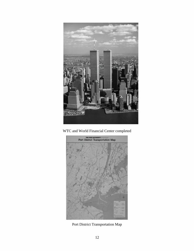
WTC and World Financial Center completed
Port District Transportation Map

13
Geologic Section Thru Dey Street
Pre- Construction Utility Excavation

14
Garage Structure Estimate
Garage Slurry Wall Alternate Estimate
15
Sequence of Slurry Wall Const.
Rendering of Slurry Wall Const. Stages

16
Pre-Excavation Basement Site (Motorola)
Slurry Wall Reinforcing Cage being lowered
17
Wall Anchor Installation
Anchor Weldment
18
WTC Perimeter Wall Panel V16, Horizontal Movement, Anchor Loads
WTC Perimeter Wall Panel G21, Horizontal Movement, Anchor Loads, Subway

19
WTC Perimeter Wall, Horizontal Movement, Anchor Loads, (W35, West Street)
Tie Back Load vs Time, Panel W35, WTC, (dates of stressing 1/29/68 to 6/21/68)

20
Tie Back Load vs Time, Panel W35 Tie T1, WTC, (Measured and Computed Tie Loads)
PATH Tube Section thru un-excavated Basement Rendering

21
Steel Strap Supporting Path Tube
Truss Supporting North PATH Tube, berm, anchor installation

22
Construction Bridge, Truss, Caissons, Piez., Slope Incl Casings, Earth slopes
PATH Tube Saddles supported by truss, steel straps between saddles

23
Caisson Supporting PATH truss
Basement excavation, construction bridges under construction, berms & earth slopes, north
PATH tube supported

24
Supported PATH tube at West Street Slurry Wall
Supported PATH Tube at Greenwich Street Slurry Wall, beneath BMT Subway

25
Completed Greenwich Slurry Wall & supported PATH Tube
Drawing - Site of Hudson River Land Fill Project, 24 Acres, (Future Battery Park City
Site)

26
Basement excavation, construction bridges, north PATH tube, AT&T building
Cofferdam Construction ( Cofferdam being filled with Sand)

27
Cofferdams, piers to be demolished, (South West area at different stages of construction)
Site of future Battery Park City (Cofferdams mostly completed, filling with WTC materials
started)

28
Basement excavation, both tubes exposed, considerable fill placed in Land Fill site, two
interior construction bridges
Land Fill site (essentially completed, installing Pump Station sheeting)

29
Steel grillages being constructed for North Tower adjacent to supported North PATH Tube
Drawing - Field Measurements of Maximum Radial Particle Velocity versus Scaled Range

30
Load Cells utilized for full scale footing load test on Manhattan Schist Rock, (E =
200,000psi, 1/100 of intact rock)
Tower Footing Construction, PATH Tube structurally supported

31
North and South towers erected with cranes, interior towers in core area supporting four
cranes are shown, decking
Lifting prefabricated outside wall section

32
Steel erection utilizing Kangaroo cranes
Construction of basement floors (they will laterally support Slurry Walls after anchors are
cut

33
DUPLICATE of 48
North and South towers, Land Fill area, partial demolition completed East of Greenwich Street, (BMT tunnel not exposed)

34
Towers construction observed from basement
Towers completed, Battery Park construction

35
Wp1010052
WTC Destr.

36
Unbraced columns
Wall & Excav Equip, Demol. Looking at Winter Garden, Earth Ramp

37
Arnold, John, Liberty Wall, PATH Proj Bracing
Anchor Installation SE corner
38
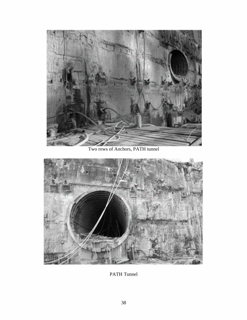
Two rows of Anchors, PATH tunnel
PATH Tunnel

39
Ray, Arnold and Peter
Statue of liberty in front of completed WTC and World Financ ial Center