workshop manual gp 1 gp series atlantis - piaggio …piaggio.co.rs/files/piaggiofreemanual.pdf ·...
TRANSCRIPT
73
WORKSHOP MANUAL
GP 1GP SERIESATLANTIS
* 50 C.C. ENGINE PIAGGIO
3

74
SPECIAL TOOLS
Description Reference
1 - Bearing extractor..............................................................................................004499Y2 - Heat gun...........................................................................................................020151Y3 - Needle bearing punch......................................................................................020080Y4 - Magneto extractor ............................................................................................020162Y5 - Heat gun holder................................................................................................020150Y 6 - Crankcase separator........................................................................................020163Y7 - Semi-pulley assembly sleeve...........................................................................020164Y8 - Water-pump impeller retaining tool ..................................................................020167Y 9 - Starter crown wheel retaining tool....................................................................020165Y10 - Crankcase-half water-seal assembly punch....................................................020168Y

75
SPECIAL TOOLS
Description Reference
11 - Spring clip assembly tool .................................................................................020166Y12 - Water-pump drive shaft (dis)assembly wrench ................................................020169Y13 - Mixer drive gear extractor tool..........................................................................020361Y14 - Starter spring assembly tool.............................................................................020261Y15 - Comparator and holder ....................................................................................020335Y 16 - Crankshaft support...........................................................................................020163Y17 - Crankshaft seal punch .....................................................................................020340Y18 - Valve separation tool........................................................................................020341Y 19 - Piston ring assembly tool .................................................................................020344Y

76
SPECIAL TOOLS
Description Reference
20 - Compressor crankshaft pulley retaining tool ....................................................020342Y21 - Magneto retaining tool......................................................................................020346Y22 - Starter crown wheel retainer ............................................................................020343Y23 - Crown wheel retainer .......................................................................................020565Y24 - Engine support .................................................................................................005095Y 25 - Extractor tool ....................................................................................................001467Y

77
Km 1000 2500 5000 10000 15000 20000 25000
Months 2 6 12 24 36
Reduction gear or crankcase oil Replace Check Check Replace Check Replace Check
Check cylinder air Clean
Suspensions Check Check Check Check Check
Tighten fastenings Check Check Check Check Check Check Check
Electrical Connections Check Check Check Check Check Check Check
Spark plug Clean Adjust Replace Replace Replace Replace Replace
Battery Check Check Check Check Check Check
Carburettor Adjust / Clean Adjust / Clean Adjust / Clean Adjust / Clean Adjust / Clean Adjust / Clean Adjust / Clean
Oil pump / Fuel valve Adjust Adjust Adjust Adjust Adjust Adjust AdjustVariable speed rollers /
Transmission belt Check Replace
Oil Filter Check Replace Check Replace Check
Air Filter Clean Clean Clean Clean Clean
Secondary Air Filter Clean Clean Clean Clean Clean
Brakes / Pads Check Check Check Check Check
Brake equipment Check Check
Brake fluid EVERY 2 YEARS EVERY 2 YEARS
Tyres Check Check Check Check Check
Tyre pressures Check Check Check Check Check Check Check
Fuel or oil hoses Check Replace Check Replace Check
Transmission Lubricate Lubricate Lubricate Lubricate Lubricate
Starter gears to pedal Clean Clean Clean Clean Clean
and grease and grease and grease and grease and grease
REGULAR MAINTENANCE CHART
GP1 - GP Series O2 - ATLANTIS
Period: this period canbe calculated by kilometresrun or by time in months

78
DESCRIPTION TORQUE SETTINGNw x m
CALIPER ROTATION SHAFT 8M125 17 - 19 LOCTITE
CYLINDER STUD 6M100 STUD 10 - 12
CRANKCASE HALVES JOINT 6M100 SCREW 12 - 13
CYLINDER HEAD 6M100 NUT 10 - 11
INLET MANIFOLD VALVE SUPPORT SCREW 1 - 2 LOCTITE
CRANKCASE INLET MANIFOLD SCREW 9 - 10 LOCTITE
OIL PUMP 5M80 SCREW 3 - 4
COIL TO BASE PLATE SCREW 8 - 10
BASE PLATE TO CRANKCASE SCREW 8 - 10
MAGNETO NUT 40 - 44 LOCTITE
PICK-UP SCREW SCREW 4 - 5
STARTER MOTOR 6M100 SCREW 12 - 13
FAN TO MAGNETO SCREW 3 - 4
LEFT-HAND CRANKCASE HALF NUT 40 - 44
REDUCTION GEAR COVER 6M100 SCREW 12 - 13
PULLEY SHAFT NUT 40 - 44 LOCTITE
CLUTCH NUT 50 - 60
PLASTIC OIL FILLER CAP CAP 3 - 5
LEFT-HAND CRANKCASE COVER 6M100 SCREW 12 - 13
OIL DRAIN PLUG 8M125 SCREW 17 - 19
CYLINDER SLEEVE COVER 6M100 SCREW 4 - 5
FRONT WHEEL 12M150 NUT 35 - 50
REAR RIM SECURING NUT NUT 17 - 19
HUB TO REAR WHEEL AXLE 16M150 NUT 115 - 125
ENGINE SUPPORT TO FRAME 10M150 NUT 30 - 40
SHOCK ABSORBER UP/ DOWN 10M150 NUT 30 - 40
HANDLEBAR 8M125 SCREW 15 - 19
EXHAUST PIPE TO CYLINDER 6M100 SCREW 9 - 12
EXHAUST PIPE TO CRANKCASE 10M150 SCREW 15 - 19
FORK LEG SECURING NUT 6M100 NUT 8 - 10
STEERING 25M100 NUT 90 - 130
FRONT BRAKE CALIPER 8M125 SCREW 17 - 19
BRAKE CALIPER TO CRANKCASE 8M125 SCREW 17 - 19
STARTER PEDAL 6M100 SCREW 8 - 12
SILENCER PROTECTOR 4M70 SCREW 1 - 2 LOCTITE
HANDLEBAR COUNTERWEIGHT SCREW 4 - 5 LOCTITE
ENGINE TO SUPPORT 10M150 SCREW 30 - 40
BRAKE DISC FRONT / REAR 8M125 SCREW 17 - 19 LOCTITE
CENTRE STAND TO CRANKCASE SCREW 17 - 19
TORQUE SETTINGS

79
FOR PROPER MAINTENANCE AND REPAIR OFTHE PAIOLI FORKS, IT IS RECOMMENDEDTHAT THEY SHOULD BE REMOVED FROM THEFRAME.
TO REMOVE THE FORKS FROM THE FRAME:
- Remove the fairing.
- Loosen off the screws in the upper casing.
- Disconnect the connections in the instrumentpanel, Speedometer sleeve, instrument connec-tors, grip lighting switch connectors, stop light,indicators, and cut the rear brake clip,
- Remove upper casing.
- Remove the shield backing plate.
- Loosen and remove the 2 handlebar screws.
- Loosen the front forks nut.
- Loosen and remove the 4 mudguard screws.
- Loosen the wheel shaft nut, remove the washer,
- Loosen the 2 front brake caliper screws.
- Loosen the locking screw, remove the wheelshaft, the wheel spacer, and leave the speedome-ter cable hanging free.
- Remove the forks.
STRIPPING THE LEFT / RIGHT FORK LEG
PAIOLI FRONT FORKS
80
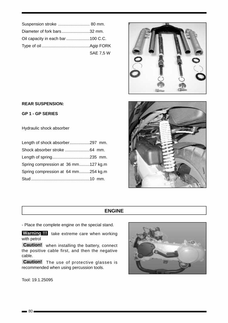
Suspension stroke ........................... 80 mm.
Diameter of fork bars........................32 mm.
Oil capacity in each bar ....................100 C.C.
Type of oil .........................................Agip FORK
SAE 7,5 W
REAR SUSPENSION:
GP 1 - GP SERIES
Hydraulic shock absorber
Length of shock absorber.................297 mm.
Shock absorber stroke .....................64 mm.
Length of spring................................235 mm.
Spring compression at 36 mm.........127 kg.m
Spring compression at 64 mm.........254 kg.m
Stud ..................................................10 mm.
ENGINE
- Place the complete engine on the special stand.
take extreme care when workingwith petrol
when installing the battery, connectthe positive cable first, and then the negativecable.
The use of protective glasses isrecommended when using percussion tools.
Tool: 19.1.25095
Warning !!!
Caution!
Caution!
81
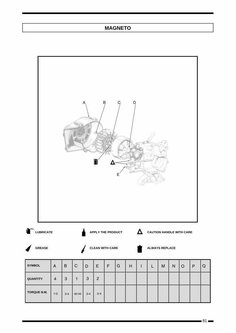
÷ ÷ ÷ ÷ ÷
LUBRICATE
GREASE
APPLY THE PRODUCT
CLEAN WITH CARE
CAUTION HANDLE WITH CARE
ALWAYS REPLACE
SYMBOL
QUANTITY
TORQUE N.M.
MAGNETO

82
Starter motor
- The securing nuts are the one indicated in thedrawing and the one diametrically opposite.
Flying cover
- Remove the four screws covers steering wheel.
- Models cooled by liquid.
Fan Cover
- Remove the four screws and disengage the twolugs inserted in the cylinder cooling jacket.
- If the vehicle is used for off-road duty, it is advisa-ble to remove the outer part of the cover andclean the silencer element with compressed airand/or water.
Magneto
Extractor: 19.1.20162
Magneto securing nut
- During this operation, secure the magneto usingthe special tool for this purpose.
Special tool: 19.1.20565
83
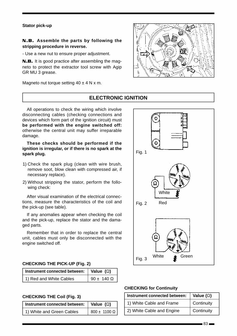
Stator pick-up
N.B. Assemble the parts by following thestripping procedure in reverse.
- Use a new nut to ensure proper adjustment.
N.B. It is good practice after assembling the mag-neto to protect the extractor tool screw with AgipGR MU 3 grease.
Magneto nut torque setting 40 ± 4 N x m.
All operations to check the wiring which involvedisconnecting cables (checking connections anddevices which form part of the ignition circuit) mustbe performed with the engine switched off:otherwise the central unit may suffer irreparabledamage.
These checks should be performed if theignition is irregular, or if there is no spark at thespark plug.
1) Check the spark plug (clean with wire brush,remove soot, blow clean with compressed air, ifnecessary replace).
2) Without stripping the stator, perform the follo-wing check:
After visual examination of the electrical connec-tions, measure the characteristics of the coil andthe pick-up (see table).
If any anomalies appear when checking the coiland the pick-up, replace the stator and the dama-ged parts.
Remember that in order to replace the centralunit, cables must only be disconnected with theengine switched off.
ELECTRONIC IGNITION
White
Fig. 2
Fig. 3
Fig. 1
Red
White Green
CHECKING THE PICK-UP (Fig. 2)
Instrument connected between: Value (Ω)
1) Red and White Cables 90 ± 140 Ω
CHECKING THE Coil (Fig. 3)
Instrument connected between: Value (Ω)
1) White and Green Cables 800 ± 1100 Ω
CHECKING for Continuity
Instrument connected between: Value (Ω)
1) White Cable and Frame Continuity
2) White Cable and Engine Continuity

84
TRANSMISSION - MIXER
÷ ÷ ÷ ÷ ÷ ÷ ÷÷
LUBRICATE
GREASE
APPLY THE PRODUCT
CLEAN WITH CARE
CAUTION HANDLE WITH CARE
ALWAYS REPLACE
SYMBOL
QUANTITY
TORQUE N.M.
85
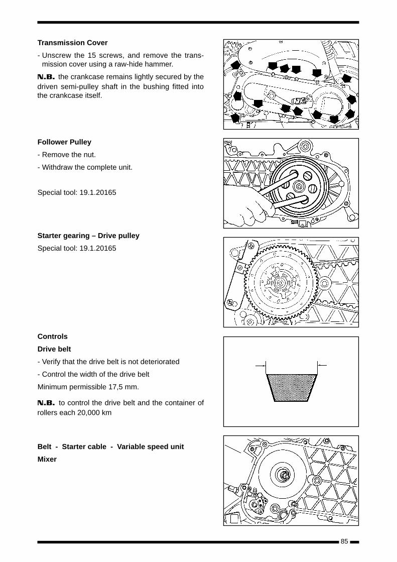
Transmission Cover
- Unscrew the 15 screws, and remove the trans-mission cover using a raw-hide hammer.
N.B. the crankcase remains lightly secured by thedriven semi-pulley shaft in the bushing fitted intothe crankcase itself.
Follower Pulley
- Remove the nut.
- Withdraw the complete unit.
Special tool: 19.1.20165
Starter gearing – Drive pulley
Special tool: 19.1.20165
Controls
Drive belt
- Verify that the drive belt is not deteriorated
- Control the width of the drive belt
Minimum permissible 17,5 mm.
N.B. to control the drive belt and the container ofrollers each 20,000 km
Belt - Starter cable - Variable speed unit
Mixer

86
Movil semi pulley
- Remove the three screws and the cover.
Variable speed plate
- Remove the O-ring and the variable speed plate.
Rollers
- Withdraw the rollers. Lift out the rollers, markingthem with a felt pen to ensure correct re-assembly.
Rollers
- Check that the rollers are not damaged or worn.
Limit of wear 18.5 mm minimum diameter.
Transmission - mixer variable speed unit
- Check that the interior bushing shows no sign ofunusual wear and measure the interior diameter.
Maximum permitted diameter 20.12 mm max.
N.B. Do not lubricate or clean the anti-frictionbushing.

87
Pulley displacement bush
- Measure the external diameter of the slidingpulley bush.
Minimum permissible diameter 19.95 mm
Variable Speed unit roller ramps
- Grease the working surfaces of the rollers usingAgip GR MU 3 grease, and re-assemble therollers.
N.B. For correct assembly, if the rollers are notbeing replaced, re-fit them into their original sea-tings.
Variador guide
- Assemble the roller cover, the oil plate, and thecover, securing with the three screws.
- Assemble the roller backing plate, the oil seal,and the cover, securing with the three screws.
Follower Pulley
- Check that the clutch casing is not worn or dama-ged.
- Measure the internal diameter of the clutchcasing. Maximum diameter value 107.5 mm.
N.B. Mount it on the appropriate shaft and checkfor eccentricity: maximum value 0.20 mm.
88
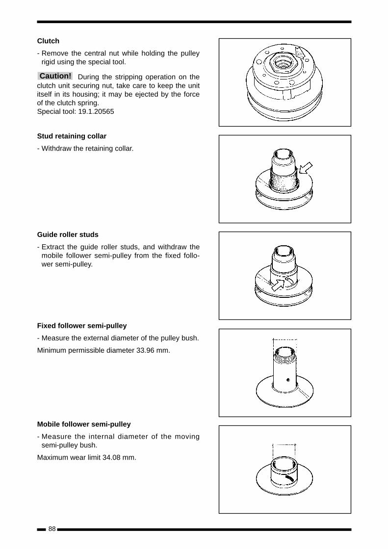
Clutch
- Remove the central nut while holding the pulleyrigid using the special tool.
During the stripping operation on theclutch unit securing nut, take care to keep the unititself in its housing; it may be ejected by the forceof the clutch spring.Special tool: 19.1.20565
Stud retaining collar
- Withdraw the retaining collar.
Guide roller studs
- Extract the guide roller studs, and withdraw themobile follower semi-pulley from the fixed follo-wer semi-pulley.
Fixed follower semi-pulley
- Measure the external diameter of the pulley bush.
Minimum permissible diameter 33.96 mm.
Mobile follower semi-pulley
- Measure the internal diameter of the movingsemi-pulley bush.
Maximum wear limit 34.08 mm.
Caution!

89
Spring
- Measure the length of the moving follower semi-pulley spring.
Minimum permissible length limit 110 mm.
Fixed follower semi-pulley bushing
- Extract the old bushings and insert new replace-ments, using a piece of tubing of the right diame-ter as a punch.
Checking the Clutch
- The clutch assembly should be replaced whenthe joint is less than 1 mm at its thinnest part.
- This assembly should be replaced as a completeunit, because it is balanced after assembly of theclutch weights.
Re-assembly of the semi-pulley
- Insert the mobile semi-pulley into the fixed semi-pulley using the protective sleeve, after replacingthe sealing rings and the O-rings, fit the studswith their respective rollers using a small quantityof Agip GR MU 3 grease.
- After completing this operation it is necessary toapply, using a curved point syringe, a sufficientquantity of grease such that when it is injectedthrough one of the holes situated in the interior ofthe bushing, it squeezes out of the opposite hole.
Special tool: 19.1.20164

90
Re-assembly of the clutch
- Refit the stud retaining collar, the spring, theclutch assembly, and lock the clutch nut.
During the stripping operation on theclutch unit securing nut, take care to keep the unititself in its housing; it may be ejected by the forceof the clutch spring.
Special tool: 19.1.20565
Torque setting: 40 ÷ 44 N x m
Loctite 242 Nut sealing paste
Mixer drive gear and belt
- Withdraw the gear and the belt.
Do not twist or fold the belt duringassembly.
During assembly, carefully lubricatethe mixer drive stud and bush, using only CONS-TANT GLY 21000 oil, and make sure that it is freeto move.
N.B. Replace the belt every 20,000 kilometres.
Follower pulley, clutch, belt
- Assemble the follower pulley - clutch - beltassembly.
Clutch hub
- Assemble the clutch hub and tighten the nut whileholding the hub itself rigid by means of the spe-cial tool.
N.B. On assembly, use new nuts and applyLoctite “Super Fast” type 242 E.Special tool 19.1.20565
Torque setting 40 ÷ 44 N x m
Caution!
Caution!
Caution!

91
Bushing and mobile semi-pulley
- Fit the assembly while taking care not to damagethe transmission belt.
- It is essential to open out the rear pulley in orderto fit the belt. It is vitally important when tighte-ning the front pulley assembly to ensure that thebelt is free to move inside it, otherwise the semi-pulley may not be tightened correctly.
Mixer - Starter cable - Belt Fixed semi-pulley- Handle with care so as to avoid twisting the belt.
Fan - Fan securing disc - Washer - Nut
- Apply recommended thread sealer
use only nuts supplied as originalspare parts.
N.B. When assembling use new nuts in order toensure correct engagement.
Torque setting: 40 ÷ 44 N x m
Special tool: 19.1.20165
Loctite 242 E
Reduction gear cover
- Before carrying out this operation, drain the oilfrom the reduction gear by means of the drainplug.
Caution!
92
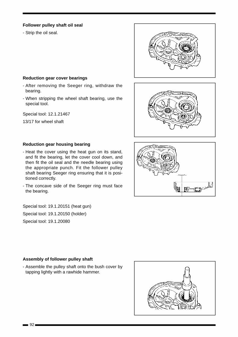
Follower pulley shaft oil seal
- Strip the oil seal.
Reduction gear cover bearings
- After removing the Seeger ring, withdraw thebearing.
- When stripping the wheel shaft bearing, use thespecial tool.
Special tool: 12.1.21467
13/17 for wheel shaft
Reduction gear housing bearing
- Heat the cover using the heat gun on its stand,and fit the bearing, let the cover cool down, andthen fit the oil seal and the needle bearing usingthe appropriate punch. Fit the follower pulleyshaft bearing Seeger ring ensuring that it is posi-tioned correctly.
- The concave side of the Seeger ring must facethe bearing.
Special tool: 19.1.20151 (heat gun)
Special tool: 19.1.20150 (holder)
Special tool: 19.1.20080
Assembly of follower pulley shaft
- Assemble the pulley shaft onto the bush cover bytapping lightly with a rawhide hammer.

93
Reduction gearing
N.B. If necessary when withdrawing the reductiongearing, use a plastic hammer, tapping lightly onthe opposite side to that shown in the figure.
Crankcase bearings
- Wheel shaft bushing:
- Withdraw the oil seal and the Seeger ring, extractthe bushing.
- Follower pulley shaft bushing.
- Use the special tool.
N.B. Perform the same operations on the bea-rings in the crankcase cover.
Extractor tool 19.1.21467/21/17
Crankcase bearings
- Heat up the crankcase halves to approximately80ºC, and then assemble the bearings.
Support 19.1.20150
Heat gun 19.1.20151
Crankcase bearings
place the stop washers correctly onthe intermediate shaft.Caution!

94
Mating the crankcase halves
- Apply Loctite 510 to the mating surfaces.
- Tighten the screws to the prescribed torque set-ting.
N.B. Always check that the compensator ring iscorrectly in place and well-greased.
Torque settings 12 ÷ 13 N x m
Replacing the starter pedal
- Remove the screw as shown in the figure andwithdraw the starter pedal.
- For re-assembly follow the same operation inreverse, and tighten to the specified torque set-ting.
Torque setting: 12-13 N·m
Replacement of the toothed segment and star-ter-crankshaft gearing
- Remove the Seeger ring situated on the outsideof the crankcase.
- Strip the starter gearing from its housing, relaxingthe pressure exerted by the toothed segmentthrough the spring; in order to do this, it is neces-sary to rotate the toothed segment slightly (seefigure).
During the stripping operation on thetoothed segment, take extreme care over the ten-sion exerted by the spring: this could injure theoperator.
Assembling the toothed segment and startergearing into the crankcase
- When assembling, apply Agip GR MU to thebush, to the spring, and along the toothed seg-ment.
- To load the spring, use the special tool as shownin the figure.
- Fit the Seeger ring after checking that it is in per-fect condition.
Special tool: 19.1.20261
Replacing the reduction gear cover bearing
- In order to replace the bearing in the reductiongear cover, heat up the crankcase and extract thebearing by tapping with gentle blows from a raw-hide hammer.
Special tool: 19.1.20150
Special tool: 19.1.20151
Caution!

95
CYLINDER HEAD - CYLINDER - PISTON
LUBRICATE
GREASE
APPLY THE PRODUCT
CLEAN WITH CARE
CAUTION HANDLE WITH CARE
ALWAYS REPLACE
SYMBOL
QUANTITY
TORQUE N.M.÷ ÷ ÷ ÷ ÷
Liquid cooled models

96
Thermostat - cylinder head - by-pass tube
Detail of the thermostat
Cylinder head - Cylinder
Every time the cylinder head is strip-ped down, replace the two seals and the cylinderhead gasket.
Cylinder
Caution!
97
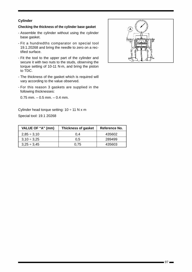
Cylinder
Checking the thickness of the cylinder base gasket
- Assemble the cylinder without using the cylinderbase gasket.
- Fit a hundredths comparator on special tool19.1.20268 and bring the needle to zero on a rec-tified surface.
- Fit the tool to the upper part of the cylinder andsecure it with two nuts to the studs, observing thetorque setting of 10-11 N·m, and bring the pistonto TDC.
- The thickness of the gasket which is required willvary according to the value observed.
- For this reason 3 gaskets are supplied in thefollowing thicknesses:
0.75 mm. – 0.5 mm. – 0.4 mm.
Cylinder head torque setting: 10 ÷ 11 N x m
Special tool: 19.1 20268
VALUE OF “A” (mm) Thickness of gasket Reference No.
2,85 ÷ 3,10 0,4 4356023,10 ÷ 3,25 0,5 2894993,25 ÷ 3,45 0,75 435603

98
CRANKCASE HALVES - CRANKSHAFT
÷ ÷
LUBRICATE
GREASE
APPLY THE PRODUCT
CLEAN WITH CARE
CAUTION HANDLE WITH CARE
ALWAYS REPLACE
SYMBOL
QUANTITY
TORQUE N.M.
99
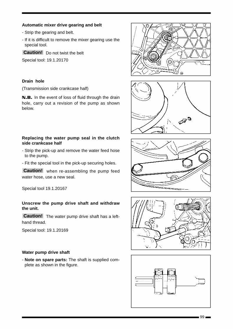
Automatic mixer drive gearing and belt
- Strip the gearing and belt.
- If it is difficult to remove the mixer gearing use thespecial tool.
Do not twist the belt
Special tool: 19.1.20170
Drain hole
(Transmission side crankcase half)
N.B. In the event of loss of fluid through the drainhole, carry out a revision of the pump as shownbelow.
Replacing the water pump seal in the clutchside crankcase half
- Strip the pick-up and remove the water feed hoseto the pump.
- Fit the special tool in the pick-up securing holes.
when re-assembling the pump feedwater hose, use a new seal.
Special tool 19.1.20167
Unscrew the pump drive shaft and withdrawthe unit.
The water pump drive shaft has a left-hand thread.
Special tool: 19.1.20169
Water pump drive shaft
- Note on spare parts: The shaft is supplied com-plete as shown in the figure.
Caution!
Caution!
Caution!
100
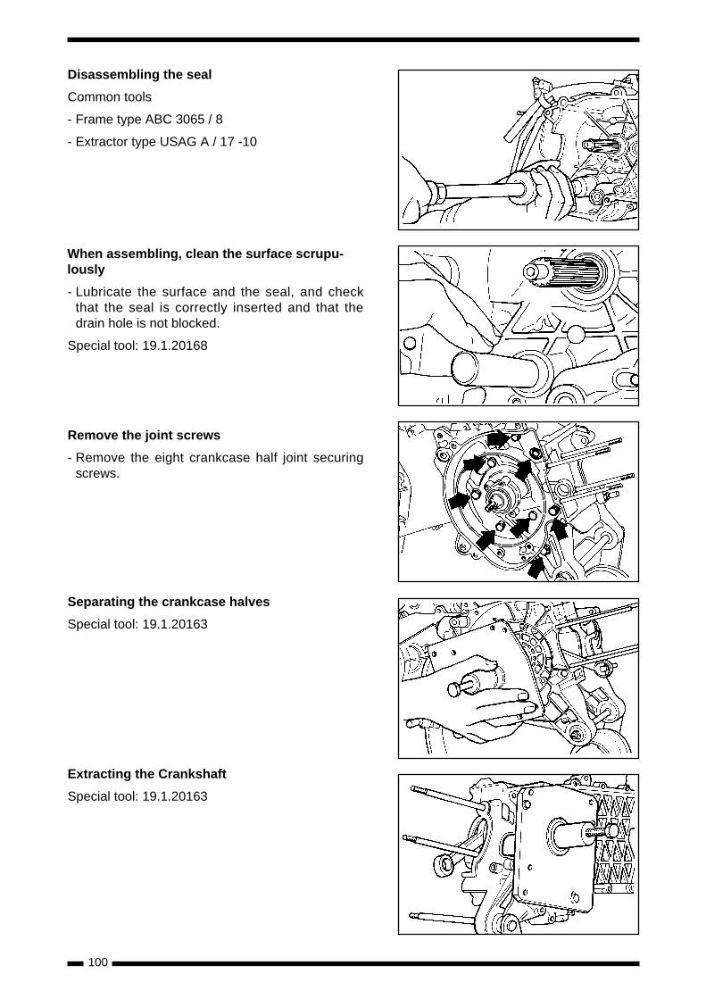
Disassembling the seal
Common tools
- Frame type ABC 3065 / 8
- Extractor type USAG A / 17 -10
When assembling, clean the surface scrupu-lously
- Lubricate the surface and the seal, and checkthat the seal is correctly inserted and that thedrain hole is not blocked.
Special tool: 19.1.20168
Remove the joint screws
- Remove the eight crankcase half joint securingscrews.
Separating the crankcase halves
Special tool: 19.1.20163
Extracting the Crankshaft
Special tool: 19.1.20163
101
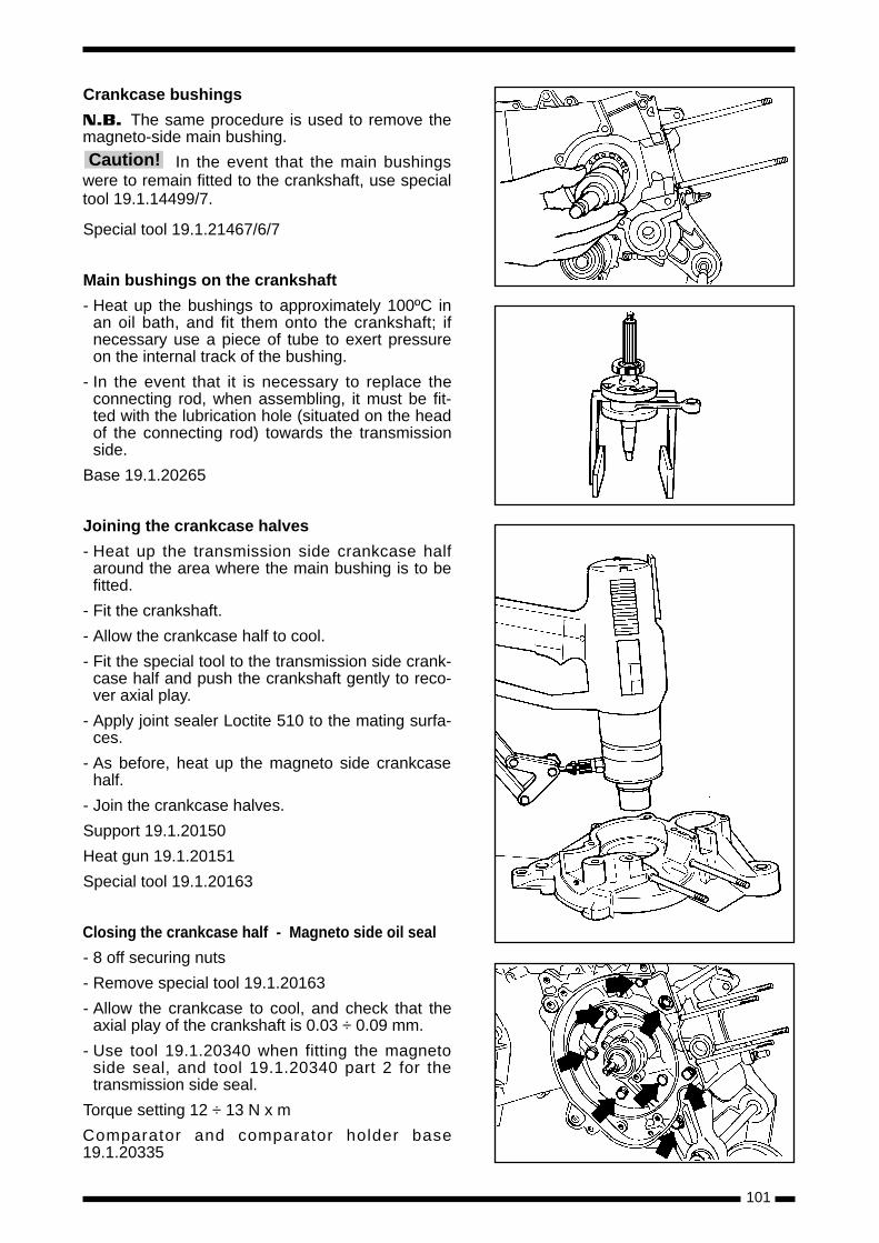
Crankcase bushings
N.B. The same procedure is used to remove themagneto-side main bushing.
In the event that the main bushingswere to remain fitted to the crankshaft, use specialtool 19.1.14499/7.
Special tool 19.1.21467/6/7
Main bushings on the crankshaft
- Heat up the bushings to approximately 100ºC inan oil bath, and fit them onto the crankshaft; ifnecessary use a piece of tube to exert pressureon the internal track of the bushing.
- In the event that it is necessary to replace theconnecting rod, when assembling, it must be fit-ted with the lubrication hole (situated on the headof the connecting rod) towards the transmissionside.
Base 19.1.20265
Joining the crankcase halves
- Heat up the transmission side crankcase halfaround the area where the main bushing is to befitted.
- Fit the crankshaft.
- Allow the crankcase half to cool.
- Fit the special tool to the transmission side crank-case half and push the crankshaft gently to reco-ver axial play.
- Apply joint sealer Loctite 510 to the mating surfa-ces.
- As before, heat up the magneto side crankcasehalf.
- Join the crankcase halves.
Support 19.1.20150
Heat gun 19.1.20151
Special tool 19.1.20163
Closing the crankcase half - Magneto side oil seal
- 8 off securing nuts
- Remove special tool 19.1.20163
- Allow the crankcase to cool, and check that theaxial play of the crankshaft is 0.03 ÷ 0.09 mm.
- Use tool 19.1.20340 when fitting the magnetoside seal, and tool 19.1.20340 part 2 for thetransmission side seal.
Torque setting 12 ÷ 13 N x m
Comparator and comparator holder base19.1.20335
Caution!

102
SECONDARY AIR SYSTEM
LUBRICATE
GREASE
APPLY THE PRODUCT
CLEAN WITH CARE
CAUTION HANDLE WITH CARE
ALWAYS REPLACE
SYMBOL
QUANTITY
TORQUE N.M.

103
Disassembly of Secondary Air System Cover
- To disconnect the metallic tube, indicated in thefigure, of the rubber seat on the cover, withoutunplugging the same tube of the cover.
- Remove screws of cover "SAS" in aluminum.
- Remove the plastic cover, the lamina and thefoam.
To each assembly to replace theO–Ring lodged in its own lodging in the cover.
Disassembling the Secondary Air System(SAS) housing
- Remove the two screws securing the SAS hou-sing to the crankcase, loosen the clip from thehose and withdraw the hose without cracking it.
Checking the SAS reed
Verify that the steel reed seals herme-tically. If it does not seal correctly, it must be repla-ced. - In order to check the oil pump, withdraw the rub-
ber cover, levering off by means of a screwdriver.
Cleaning the filter
- Wash both filters with soap and water.
- Dry using compressed air before re-installing.
- Remove the securing clamp, and then withdrawthe hose from the secondary air filter to theexhaust pipe.
Atención
Caution!

104
CYLINDER HEAD - CYLINDER - PISTON
÷ ÷÷ ÷
LUBRICATE
GREASE
APPLY THE PRODUCT
CLEAN WITH CARE
CAUTION HANDLE WITH CARE
ALWAYS REPLACE
SYMBOL
QUANTITY
TORQUE N.M.
Models air cooled

105
Cylinder cooling cover
- Withdraw the screws shown in the figure.
Cylinder Head
- Remove the 4 nuts indicated in the figure.
Cylinder
- Exercise great care when withdrawing the cylin-der.
Piston
- Remove the spring clips and withdraw the gudge-on pin.
Replace the spring clips securing thegudgeon pin every time the assembly is stripped.
Reed Valve
Check that the reed assembly closescorrectly; no light should be seen between thereeds and the valve body.
Caution!
Caution!
106
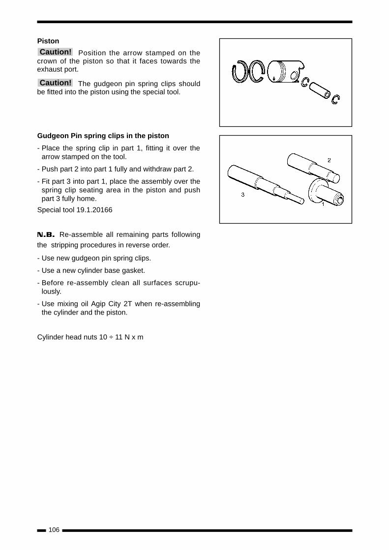
Piston
Position the arrow stamped on thecrown of the piston so that it faces towards theexhaust port.
The gudgeon pin spring clips shouldbe fitted into the piston using the special tool.
Gudgeon Pin spring clips in the piston
- Place the spring clip in part 1, fitting it over thearrow stamped on the tool.
- Push part 2 into part 1 fully and withdraw part 2.
- Fit part 3 into part 1, place the assembly over thespring clip seating area in the piston and pushpart 3 fully home.
Special tool 19.1.20166
N.B. Re-assemble all remaining parts following
the stripping procedures in reverse order.
- Use new gudgeon pin spring clips.
- Use a new cylinder base gasket.
- Before re-assembly clean all surfaces scrupu-lously.
- Use mixing oil Agip City 2T when re-assemblingthe cylinder and the piston.
Cylinder head nuts 10 ÷ 11 N x m
Caution!
Caution!
107
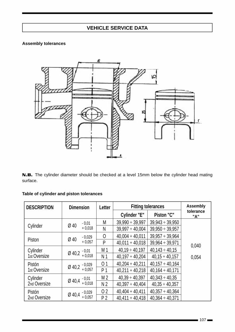
DESCRIPTION Dimension Letter Fitting tolerances
Cylinder Ø 40 - 0,01 MN+ 0,018
0,040
0,054
Assemblytolerance
"A"Cylinder "E" Piston "C"39,990 ÷ 39,997 39,943 ÷ 39,95039,997 ÷ 40,004 39,950 ÷ 39,957
Piston Ø 40 - 0,029 OP+ 0,057
40,004 ÷ 40,011 39,957 ÷ 39,96440,011 ÷ 40,018 39,964 ÷ 39,971
Cylinder1st Oversize Ø 40,2 - 0,01 M 1
N 1+ 0,01840,19 ÷ 40,197 40,143 ÷ 40,15
40,197 ÷ 40,204 40,15 ÷ 40,157Pistón1st Oversize Ø 40,2 - 0,029 O 1
P 1+ 0,05740,204 ÷ 40,211 40,157 ÷ 40,16440,211 ÷ 40,218 40,164 ÷ 40,171
Cylinder2nd Oversize Ø 40,4 - 0,01 M 2
N 2+ 0,01840,39 ÷ 40,397 40,343 ÷ 40,35
40,397 ÷ 40,404 40,35 ÷ 40,357Pistón2nd Oversize Ø 40,4 - 0,029 O 2
P 2+ 0,05740,404 ÷ 40,411 40,357 ÷ 40,36440,411 ÷ 40,418 40,364 ÷ 40,371
VEHICLE SERVICE DATA
Assembly tolerances
N.B. The cylinder diameter should be checked at a level 15mm below the cylinder head matingsurface.
Table of cylinder and piston tolerances

108
Piston Rings
- The verification of assembly tolerance should becarried out by inserting the piston ring into thecylinder at 15 ÷ 20 mm from the cylinder headmating surface, and measuring the gap betweenthe opposite ends of the ring using a set of feelergauges.
DESCRIPTION DIAMETER PLAY ASSEMBLY TOLERANCE
Piston Ring Std Ø 40
Piston Ring 1st Oversize Ø 40.2 A 0.10 ÷ 0.25
Piston Ring 2nd Oversize Ø 40.4
DESCRIPTION DIAMETER PLAY ASSEMBLY TOLERANCE
Piston P = Ø 12 + 0,007- 0,012
R 0,002 ÷ 0,011
Gudgeon Pin Q = Ø 12 + 0,005- 0,001
Checking the Gudgeon Pin
109
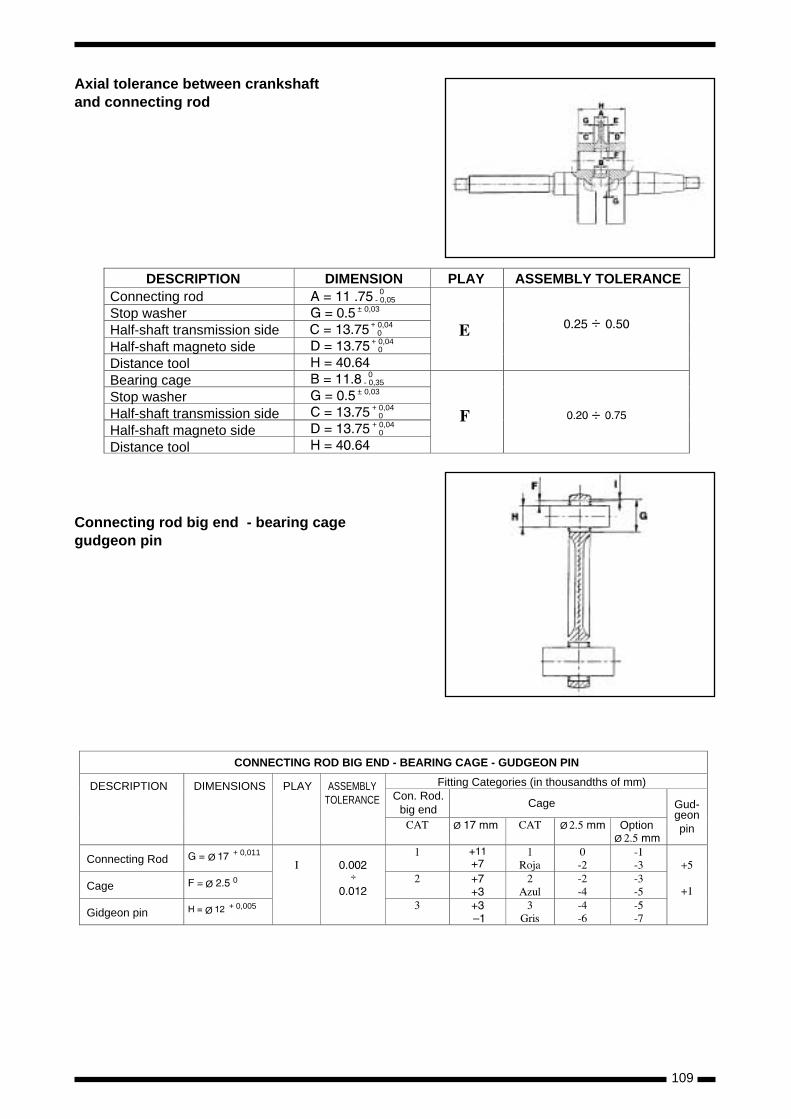
Connecting rod big end - bearing cagegudgeon pin
÷
÷
0- 0,05
± 0,03
+ 0,04 0
0- 0,35
± 0,03
+ 0,04 0+ 0,04 0
+ 0,04 0
DESCRIPTION DIMENSION PLAY ASSEMBLY TOLERANCEConnecting rodStop washerHalf-shaft transmission sideHalf-shaft magneto sideDistance toolBearing cageStop washerHalf-shaft transmission sideHalf-shaft magneto sideDistance tool
Ø
Ø
Ø
+ 0,011
0
+ 0,005
÷
ØØ
Ø
CONNECTING ROD BIG END - BEARING CAGE - GUDGEON PIN
DESCRIPTION DIMENSIONS PLAY ASSEMBLYTOLERANCE
Connecting Rod
Cage
Gidgeon pin
Fitting Categories (in thousandths of mm)
CageCon. Rod.
big end Gud-geonpinOption
Axial tolerance between crankshaftand connecting rod

110
Crankshaft alignment check
- Using the special tool indicated, check the surfa-ce of diameters “A” “B” “C” for eccentricity: theyshould fall within 0.03 mm (maximum limit of rea-ding on comparator dial). Also check eccentricityof diameter “D” for which the maximum permittedreading is 0.02 mm. Where the eccentricity isslightly greater than specifications, true thecrankshaft between the counterweights by shimbushing, or by pressing in a screw press fittedwith aluminium bushes, as required. In the eventthat it is impossible to true the shaft, or whereeccentricity is excessive, replace the crankshaft.
Axial assembly tolerance:
- Measure the axial tolerance of the crankshaft inthe crankcase, with the engine cold.
- Push and pull the crankshaft from one side, andmeasure the value using a comparator on theother side.
Assembly tolerance under load ± 3 kg:
0.03 ÷ 0.12 mm
Special tools:
Comparator with magnetic support: 020335Y
Crankshaft alignment tool: 020074Y
Adjustment Table
MAKE CARBURETTOR
DELL'ORTO
DELL'ORTO
±
±
MODEL JET
MAXIM
NEEDLE
POSITION
JET
MINIMUM
EMULSIFIER IDLE JET CHOKE
JET
FLOAT
LEVEL
Turns
Turns
CARBURETTOR

111
Yellow / GreenBlue / Black
Bulb
Checking the fuel indicator
- The fuel indicator needle operates on themoving magnet principle.
- Check carried out with voltage at 13 V DC.
Checking the temperature indicator
- The temperature indicator needle operateson the moving magnet principle.
Checking the thermistor
Checking the fuel sensor
Checking the oil sensor
Check
- Check that the oil sensor pilot light lights upfor about 10 seconds and then switches off.
Sensor
- After carrying out the check function, the lightgoes out for approximately 1 minute. Then itshould light up again.
- Once the device is active, it should not deac-tivate until power is shut off.
Marking
Tolerances
Resistance
Value in at the probe
IndexPosition
Tolerance
Temperature Resistance
FUEL SENSOR
ReserveIndicator
Analoguelevel indicator
FULL
EMPTY
FULL
EMPTY
ELECTRICAL SYSTEM

112
Fig. 4
Fig. 3
Checking the voltage regulator
- Breakdown of the voltage regulator may lead,depending on the type of breakdown, to the follo-wing types of failure:
1) Burnt-out bulbs in the lighting circuit.2) Lighting circuit fails to operate.3) Excessive battery charging.4) Battery fails to charge.5) Direction indicators fail to operate.
FAILURE 1
- Replace the regulator as it is certainly ineffective.
FAILURE 2
a) Check for proper distribution of current from thestator: disconnect from the regulator terminaland insert alternating current tester 020331Ybetween the blue/green terminal and the blackcable, and check that the voltage distributed at3,000 rpm falls between 25 ÷ 30 VAC (Fig. 1)
b) If there is no abnormality, replace the regulator.
c) If correct operation is impossible even with anew regulator, carry out a check of the connec-tions in the wiring circuit.
FAILURE 3
- After checking that there are no short-circuitsfrom the wiring circuit to ground with the enginestopped and with the regulator terminal discon-nected, replace the regulator, because it is cer-tainly ineffective; also replace the protection fuse.
- After replacement, measure charging current andvoltage at the battery terminals (Fig. 2).
FAILURE 4
a) Connect an ammeter between the stator (bluecable) and the battery and check using tester020331Y that the current distributed at 3,000rpm and with the battery at 13 V is approxima-tely 1.5 ÷ 2 Amps (Fig. 3).
If measured values are lower than specified, repla-ce the regulator.
b) If replacing the regulator does not re-establishcorrect operation, set the tester 020031Y foralternating current voltage, connect between theregulator yellow cable terminal and the blackcable (Fig.4) and check that the voltage distribu-ted by the generator at 3,000 rpm falls between26-30V (this test should be carried out with thebattery disconnected).
N.B. Before carrying out any checks on the regu-lator and the related wiring, it is recommended thata continuity check is run between the black cableand ground.
Fig. 1
Fig. 2
Grey-Blue Black
Black Yellow
Red

113
ECHEMA ELECTRIQUE ATLANTIS
OrangeGrünSchwarzBraunWeiBGrauGelbBlauRotRosaViolett
OrangeVertNoirMarronBlancGrisJauneBlauRougeRosaViolet
OrangeGreenBlackBrownWhiteGrayYellowBlueRedPinkViolet
ArancioVerdeNeroMarroneBiancoGrigioGialloAzzurroRossoRosaViola
NaranjaVerdeNegroMarronBlancoGrisAmarilloAzulRojoRosaVioleta
OGRB
BRWGYBLRPVI
D F UK I E

114
ECHEMA ELECTRIQUE GP1
OrangeGrünSchwarzBraunWeiBGrauGelbBlauRotRosaViolett
OrangeVertNoirMarronBlancGrisJauneBlauRougeRosaViolet
OrangeGreenBlackBrownWhiteGrayYellowBlueRedPinkViolet
ArancioVerdeNeroMarroneBiancoGrigioGialloAzzurroRossoRosaViola
NaranjaVerdeNegroMarronBlancoGrisAmarilloAzulRojoRosaVioleta
OGRB
BRWGYBLRPVI
D F UK I E

115
OrangeGrünSchwarzBraunWeiBGrauGelbBlauRotRosaViolett
OrangeVertNoirMarronBlancGrisJauneBlauRougeRosaViolet
OrangeGreenBlackBrownWhiteGrayYellowBlueRedPinkViolet
ArancioVerdeNeroMarroneBiancoGrigioGialloAzzurroRossoRosaViola
NaranjaVerdeNegroMarronBlancoGrisAmarilloAzulRojoRosaVioleta
OGRB
BRWGYBLRPVI
D F UK I E
ECHEMA ELECTRIQUE GP1 (USA)

116
OrangeGrünSchwarzBraunWeiBGrauGelbBlauRotRosaViolett
OrangeVertNoirMarronBlancGrisJauneBlauRougeRosaViolet
OrangeGreenBlackBrownWhiteGrayYellowBlueRedPinkViolet
ArancioVerdeNeroMarroneBiancoGrigioGialloAzzurroRossoRosaViola
NaranjaVerdeNegroMarronBlancoGrisAmarilloAzulRojoRosaVioleta
OGRB
BRWGYBLRPVI
D F UK I E
ECHEMA ELECTRIQUE GP Series