working with v net modules - documents.holley.com · when we wanted to record, the boss would say...
TRANSCRIPT
Racepak V50V50V50V50 Playback & Download Module
RECORD
PAUSE
Installation and Operation Manual

Table of Contents
Introduction -- The Racepak V_Net Systems ................................ 1 How the V_Net System Works: ...................................................................................... 2
Installing your V_Net System .................................................. 5 Step #1: Planning your V_Net Installation...................................................................... 5 Step #2: Installing the V_Net Modules ........................................................................... 5 Step #3: Installing the Power Module ............................................................................. 6 Step #4: Connecting the modules using the V_Net Cables ............................................. 6 Step #5: Installing the Terminator Caps .......................................................................... 6
PC Software Installation: ................................................................ 7 Installing the DataLink Software:.................................................................................... 7 Selecting the PC’s Serial Communication Port............................................................... 8 Enabling the V_Net AutoSync Feature ........................................................................... 9
Initializing the DataLink Software for your V50 System: ............ 11 Initializing the DataLink Software ................................................................................ 11 Action Messages encountered during Initialization: ..................................................... 12
Message: V_Net ID Not Assigned: ...................................................................................................... 12 Message: V_Net ID Already Used: ...................................................................................................... 13 Message: Missing V_Net Module ........................................................................................................ 13
Editing the Configuration of your V_Net System:....................... 15 Opening your Car configuration file for Edit: ............................................................... 15 Adding or Removing Modules from your V_Net system: ............................................ 18
Recording Data with the V_Net System:...................................... 19
Playing Back Data using the Remote Keypad............................. 21
Downloading Data to your PC:.............................................. 23
Viewing Data on Your PC: ...................................................... 25 Quick Start Tour of the DataLink User Screen ............................................................. 25 DataLink Display Screen Layout .................................................................................. 25 Channel Display Region................................................................................................ 26 Graphics Display Region............................................................................................... 27
Time Cursor.......................................................................................................................................... 28 Cursor Time Display ............................................................................................................................ 29 Channel Grid Selection Button and Display......................................................................................... 29 Average Cursor..................................................................................................................................... 29
Run Log Display Region ............................................................................................... 30 DataLink User Interface ................................................................................................ 30
Graphics Toolbar .................................................................................................................................. 30 Clear Graphs Command ....................................................................................................................... 31
2
The Set Start Time Commands............................................................................................................. 32 Using Help..................................................................................................................... 32
The Context Sensitive Help.................................................................................................................. 34 Hyperlinks Inside the Help System ...................................................................................................... 35
Viewing Real Time Data with your PC: ........................................ 37 Setting up your V50 Record Playback Module ............................................................. 37 Setting Up the DataLink Telemetry Parameters............................................................ 37 Starting a Telemetry Session. ........................................................................................ 38
Appendix V: V_Net Module Installation Instructions.................. 41
V50/V-Net Installation and Operation Manual
1
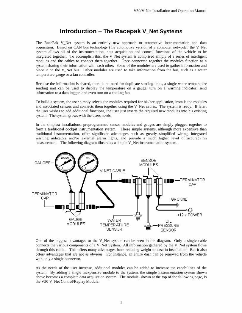
Introduction -- The Racepak V_Net Systems The RacePak V_Net system is an entirely new approach to automotive instrumentation and data acquisition. Based on CAN bus technology (the automotive version of a computer network), the V_Net system allows all of the instrumentation, data acquisition and control functions of the vehicle to be integrated together. To accomplish this, the V_Net system is comprised simply of a series of intelligent modules and the cables to connect them together. Once connected together the modules function as a system sharing their information with each other. Some of the modules are used to gather information and place it on the V_Net bus. Other modules are used to take information from the bus, such as a water temperature gauge or a fan controller. Because the information is shared, there is no need for duplicate sending units, a single water temperature sending unit can be used to display the temperature on a gauge, turn on a warning indicator, send information to a data logger, and even turn on a cooling fan. To build a system, the user simply selects the modules required for his/her application, installs the modules and associated sensors and connects them together using the V_Net cables. The system is ready. If later, the user wishes to add additional functions, the user just inserts the required new modules into his existing system. The system grows with the users needs. In the simplest installations, preprogrammed sensor modules and gauges are simply plugged together to form a traditional cockpit instrumentation system. These simple systems, although more expensive than traditional instrumentation, offer significant advantages such as greatly simplified wiring, integrated warning indicators and/or external alarm lights, and provide a much higher level of accuracy in measurement. The following diagram illustrates a simple V_Net instrumentation system.
One of the biggest advantages to the V_Net system can be seen in the diagram. Only a single cable connects the various components of a V_Net System. All information gathered by the V_Net system flows through this cable. This offers many advantages from reducing weight to ease in installation. But it also offers advantages that are not as obvious. For instance, an entire dash can be removed from the vehicle with only a single connector. As the needs of the user increase, additional modules can be added to increase the capabilities of the system. By adding a single inexpensive module to the system, the simple instrumentation system shown above becomes a complete data acquisition system. The module, shown at the top of the following page, is the V50 V_Net Control/Replay Module.
V50/V-Net Installation and Operation Manual
2
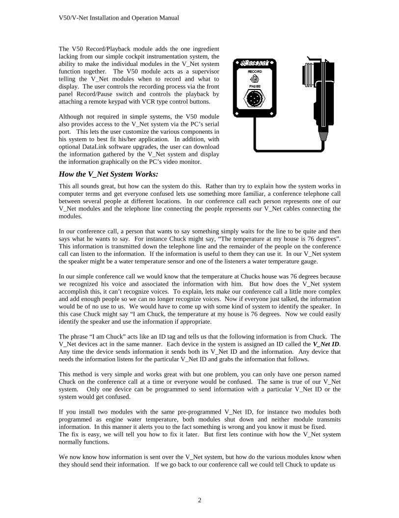
The V50 Record/Playback module adds the one ingredient lacking from our simple cockpit instrumentation system, the ability to make the individual modules in the V_Net system function together. The V50 module acts as a supervisor telling the V_Net modules when to record and what to display. The user controls the recording process via the front panel Record/Pause switch and controls the playback by attaching a remote keypad with VCR type control buttons. Although not required in simple systems, the V50 module also provides access to the V_Net system via the PC’s serial port. This lets the user customize the various components in his system to best fit his/her application. In addition, with optional DataLink software upgrades, the user can download the information gathered by the V_Net system and display the information graphically on the PC’s video monitor.
How the V_Net System Works: This all sounds great, but how can the system do this. Rather than try to explain how the system works in computer terms and get everyone confused lets use something more familiar, a conference telephone call between several people at different locations. In our conference call each person represents one of our V_Net modules and the telephone line connecting the people represents our V_Net cables connecting the modules. In our conference call, a person that wants to say something simply waits for the line to be quite and then says what he wants to say. For instance Chuck might say, “The temperature at my house is 76 degrees”. This information is transmitted down the telephone line and the remainder of the people on the conference call can listen to the information. If the information is useful to them they can use it. In our V_Net system the speaker might be a water temperature sensor and one of the listeners a water temperature gauge. In our simple conference call we would know that the temperature at Chucks house was 76 degrees because we recognized his voice and associated the information with him. But how does the V_Net system accomplish this, it can’t recognize voices. To explain, lets make our conference call a little more complex and add enough people so we can no longer recognize voices. Now if everyone just talked, the information would be of no use to us. We would have to come up with some kind of system to identify the speaker. In this case Chuck might say “I am Chuck, the temperature at my house is 76 degrees. Now we could easily identify the speaker and use the information if appropriate. The phrase “I am Chuck” acts like an ID tag and tells us that the following information is from Chuck. The V_Net devices act in the same manner. Each device in the system is assigned an ID called the V_Net ID. Any time the device sends information it sends both its V_Net ID and the information. Any device that needs the information listens for the particular V_Net ID and grabs the information that follows. This method is very simple and works great with but one problem, you can only have one person named Chuck on the conference call at a time or everyone would be confused. The same is true of our V_Net system. Only one device can be programmed to send information with a particular V_Net ID or the system would get confused. If you install two modules with the same pre-programmed V_Net ID, for instance two modules both programmed as engine water temperature, both modules shut down and neither module transmits information. In this manner it alerts you to the fact something is wrong and you know it must be fixed. The fix is easy, we will tell you how to fix it later. But first lets continue with how the V_Net system normally functions. We now know how information is sent over the V_Net system, but how do the various modules know when they should send their information. If we go back to our conference call we could tell Chuck to update us
V50/V-Net Installation and Operation Manual
3
as to the temperature of his house every 15 minutes. Chuck would then look at his watch and every 15 minutes would announce the temperature over the telephone. The V_Net modules function in the same manner. They are programmed to send their information at a fixed interval in time. This is called the V_Net Update Rate and each module is programmed with its own rate. For items that change slowly, such as water temperature the module might be programmed to send information slowly for instance once per second. For items that change rapidly the update rate may be set as high as 100 times per second. This describes how the simple instrumentation system described above functions. The next step is to make our simple system record and playback data. To see how this is done let’s again look at our conference call. As described above, we have intelligent people at each phone capable of recording data and telling us what they recorded. They, however, have no idea when to record or when to tell us what they recorded. If we want to record the data we would need someone to supervise the recording and playback. To accomplish this we would add a new person to the conference call. This person, lets call him the Boss, would control the record and playback process. When we wanted to record, the Boss would say “I am the Boss, the time is 2:15 A.M. record your information”. Each of the people on our call would record the information for that time. When we were ready to get back the information, the Boss would say “I am the Boss, tell me the information you recorded at 3:22 P.M.”. Each of the people in turn would tell us the value we recorded. The Boss in the V_Net system is the V50 Record/Playback module described above. This module supervises the remaining modules allowing them to record and playback. The user in turn controls the V50 module via the module’s Record/Pause switch and remote keypad. The Boss also has another function. Remember the problem we encountered above if we had two Chucks on our system at one time. We told you we would tell you how to fix it later. Well now is the time and the V50 module is how we fix it. To illustrate lets go back to our conference call and see how this is accomplished. On our conference call we have two speakers with the same name Chuck. The remainder of the people have no way of identifying which Chuck is speaking or even if there is more than one Chuck. They just use the information as they receive it. The two Chucks, however, can hear each other and know there are two Chucks on the line. To avoid confusing the remainder of the people they both stop talking. The owner of the conference call now notices that Chuck is missing. The owner then goes to the Boss and tells the Boss to find out who is on the call. The Boss speaks onto the phone saying “I am the Boss, tell me who is there.” Each of the people on the conference call responds by saying their name into the phone. They also add one other piece of information, their social security number. The boss can now distinguish which Chuck is which and can tell one of the Chucks to use a different name, for instance Charles. Now nobody is confused and we can go back to work. The same thing happens in the V_Net system. Every V_Net module has the equivalent of a social security number assigned at the time it is manufactured. The number is called the modules V_Net Serial Number. Every module has a unique serial number. When the user sees the V_Net system is not functioning properly, the user hooks his/her PC to the V50 module and reads in the configuration of his V_Net system. If two modules have the same V_Net ID, the program warns the user that two modules have been programmed to the same V_Net ID. The user can then reprogram one of the modules to a new V_Net ID. In the example above, one of the engine water temperatures could be assigned to a V_Net ID that better describe its function such as radiator water out temperature. You should now have a basic idea as to how the system works. Before we go on lets review some of the important items we have discussed:
V_Net Serial Number: All V_Net modules have a unique serial number. The number is used to identify a particular physical module.
V50/V-Net Installation and Operation Manual
4
V_Net ID Number:
When a V_Net module sends information over the V_Net bus the information is identified with a V_Net ID. This tells the remaining modules what the information is so they can properly use the information.
V_Net Update Rate:
All modules that place information on the V_Net bus are programmed to put the information on the bus at a fixed update rate. For instance 10 times per second.
V50/V-Net Installation and Operation Manual
5
Installing your V_Net System In this section we will take you through the installation of your new V_Net System. Step #1: Planning your V_Net Installation The first step in installing your new V_Net system is to determine where the various V_Net modules will be mounted and how the cables connecting the modules will be routed. The location of each of the modules will be determined in a large part by their function and the ability to install the sensors connected to each of the modules to the appropriate portion of your vehicle. You should try, however, to route the V_Net cables and place the modules in a manner that minimizes the number of cables required to connect the modules. Remember that the modules can be connected directly to one another and they can be placed anywhere in the V_Net cabling system. The relative location of the modules is not important. You may want to unpack your V_Net modules and place then in your vehicle to help you plan your installation. Be sure to mark the modules and components clearly to avoid confusion later when actually installing the modules. The are some important considerations that should be kept in mind when planning your installation. These are:
The blue connectors in each of the V_Net modules and the four channel thermocouple modules contain electronic components. The temperature of these components cannot exceed 180 degrees F. Select a location to mount the modules that minimizes the temperature to which the modules are exposed. Ignition systems generate large amounts of electrical noise (EMI). This noise can cause the V_Net modules to malfunction. Avoid routing or mounting any of the V_Net cables or components near the high voltage ignition wires. The V_Net components are designed to be water-resistant. They are not waterproof. Avoid mounting the components in areas where they are continually exposed to water and/or high-pressure sprays. The V_Net cables distribute 12-Volt power to the modules and are connected directly to the switched power in your vehicle. Be sure to route the cables such that they will not be pinched or otherwise damaged during the normal operation of the vehicle or during potential accidents. Shorting the cables to the chassis can cause a fire. Be sure to mount all modules and route all cables such that they do not interfere with the safe operation of the vehicle.
Step #2: Installing the V_Net Modules After you have planned your V_Net installation, the next step is to install each of the V_Net modules. The shipping carton for each of the modules will include detailed instructions on installing each of the modules. Follow the instructions for each of the modules and install the modules. When you are done installing the modules be sure to place the installation instructions in Appendix II of this manual. These instructions will be used to document your system.

V50/V-Net Installation and Operation Manual
6
Step #3: Installing the Power Module The V_Net system is powered by the vehicles 12-volt electrical system. In most applications the V_Net system will be powered any time the vehicle is in operation. As such the system should be connected to the main switched power in your vehicle. Power is supplied to the V_Net system using the V_Net Power Module included with your kit. The power module can be placed anywhere n the V_Net system, however, if your system includes a large number of gauges you should connect the power module into your V_Net system near the location of the gauges. Be sure the electrical circuit in your vehicle to which you connect the V_Net power module routes directly to the main switched power in your vehicle and if of sufficient wire gauge to provide the required power without significant voltage drop in the power wire. Step #4: Connecting the modules using the V_Net Cables After you have installed and mounted the V_Net modules in your system you are ready to connect the modules to each other using the 5 pin V_Net cables. The V_Net cable connectors and the mating connectors on each of the V_Net modules are color coded blue for easy identification. Route the cables and connect the modules. Next secure the cables to the vehicle. Step #5: Installing the Terminator Caps After your have completed the installation of your V_Net system you will need to install the two terminator caps on each end of the V_Net cable system. Each terminator cap has a termination resistor required by the V_Net system to allow the devices to communicate over the V_Net data bus. You will have a female and a male termination cap. Install each cap in the in the open connectors on the end of the V_Net cable/module system.
V50/V-Net Installation and Operation Manual
7
PC Software Installation: The V50 Record and Playback module can be connected directly to a PC type computer via the serial communications port. Once connected you can utilize the DataLink Setup software to customize the operation of your V_Net system to exactly meet your needs. In addition, by purchasing the optional DataLink software upgrades you can upload the information recorded by your V_Net system to your PC for viewing and analysis. Depending on your needs, the DataLink software can be purchased at the following levels. Each successive level includes all of the capabilities of the previous levels. DataLink Setup:
The DataLink setup software comes standard with all V50 Record and Playback modules. This software is used to setup and customize the operation of the V50 system.
DataLink File Viewer:
The DataLink File Viewer software adds the ability to upload data from your V_Net system to your PC and to view the data both numerically and graphically. All variables measured by your system can be graphed one at a time or simultaneously. Special channels are included to provide clutch or transmission slip curves when appropriate V_Net modules are installed in your onboard system. Only one file can be displayed at a time.
DataLink Lite: The DataLink Lite software adds the ability to display multiple runs simultaneously on the computer screen. The program also allows data to be transmitted from the V50 Unit and displayed real-time on the computer screen. The program also includes a Racer’s Run Log that can be customized by the user to his particular needs.
DataLink Standard: This version of the DataLink software provides full math channel support to the DataLink software. For instance, you will l need math channels if you have a g-meter and want to integrate speed and distance traveled.
DataLink Pro: The DataLink Pro software provides full access to the UniLog or Racer’s Logbook area of the DataLink software. The user can define custom run log pages including calculation spreadsheets, x-y plots, histograms, gauges and much more.
Installing the DataLink Software: Before you install the DataLink software, check the revision level of the software on the front of the CD supplied with the software. You will need version 4.5 or later to access the V_Net modules as described in this manual. Follow the instructions in the DataLink manual to install the DataLink software. You can skip the Hardware Installation step, as your system will be using a serial interface. You can also skip the Setting the Default Configuration File and Entering the Conversion File Security Key steps. During the installation process you will be asked to install a “License Disk”. In some cases you will not have a license disk. The license disk is only used if you have purchased the DataLink File Viewer or above software allowing you to upload data to a PC. If you have a license disk be sure to install the disk per the onscreen installation instructions. If you have purchased any of the upgrades to the DataLink software and did not receive a license disk, you will need to enter the security key associated with your V50 module to gain access to the software. This
V50/V-Net Installation and Operation Manual
8
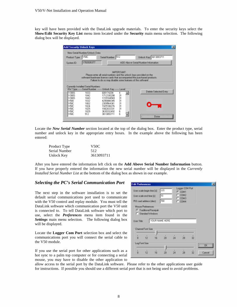
key will have been provided with the DataLink upgrade materials. To enter the security keys select the Show/Edit Security Key List menu item located under the Security main menu selection. The following dialog box will be displayed.
Locate the New Serial Number section located at the top of the dialog box. Enter the product type, serial number and unlock key in the appropriate entry boxes. In the example above the following has been entered: Product Type V50C Serial Number 512 Unlock Key 3613093711 After you have entered the information left click on the Add Above Serial Number Information button. If you have properly entered the information the new serial number will be displayed in the Currently Installed Serial Number List at the bottom of the dialog box as shown in our example. Selecting the PC’s Serial Communication Port The next step in the software installation is to set the default serial communications port used to communicate with the V50 control and replay module. You must tell the DataLink software which communication port the V50 unit is connected to. To tell DataLink software which port to use, select the Preferences menu item found in the Settings main menu selection. The following dialog box will be displayed. Locate the Logger Com Port selection box and select the communications port you will connect the serial cable to the V50 module. If you use the serial port for other applications such as a hot sync to a palm top computer or for connecting a serial mouse, you may have to disable the other application to allow access to the serial port by the DataLink software. Please refer to the other applications user guide for instructions. If possible you should use a different serial port that is not being used to avoid problems.
V50/V-Net Installation and Operation Manual
9
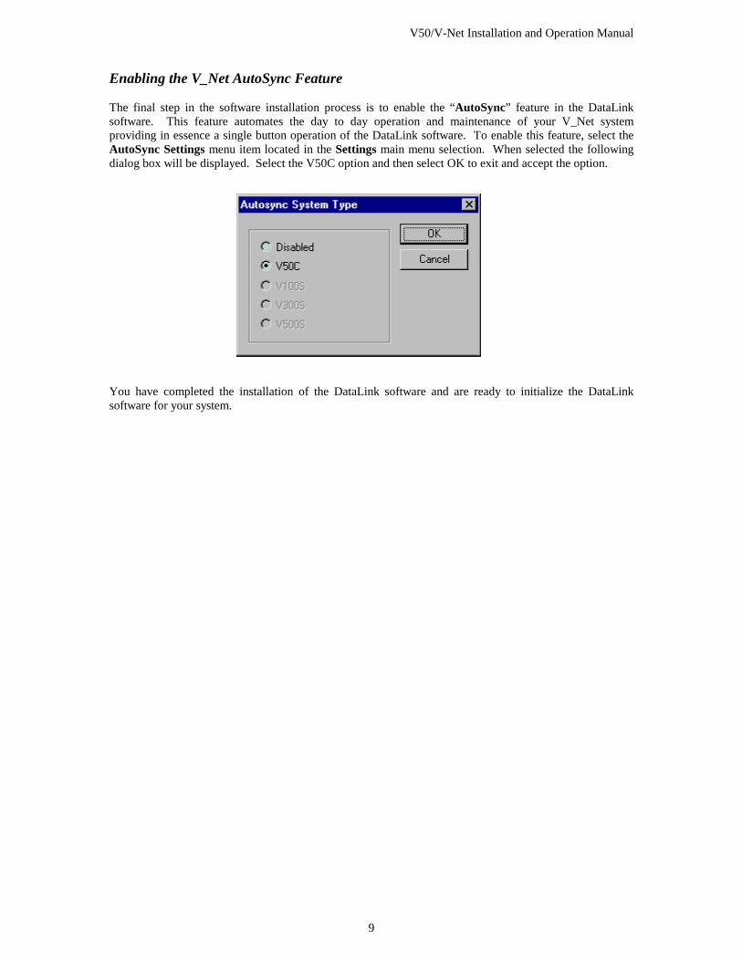
Enabling the V_Net AutoSync Feature The final step in the software installation process is to enable the “AutoSync” feature in the DataLink software. This feature automates the day to day operation and maintenance of your V_Net system providing in essence a single button operation of the DataLink software. To enable this feature, select the AutoSync Settings menu item located in the Settings main menu selection. When selected the following dialog box will be displayed. Select the V50C option and then select OK to exit and accept the option.
You have completed the installation of the DataLink software and are ready to initialize the DataLink software for your system.

V50/V-Net Installation and Operation Manual
11
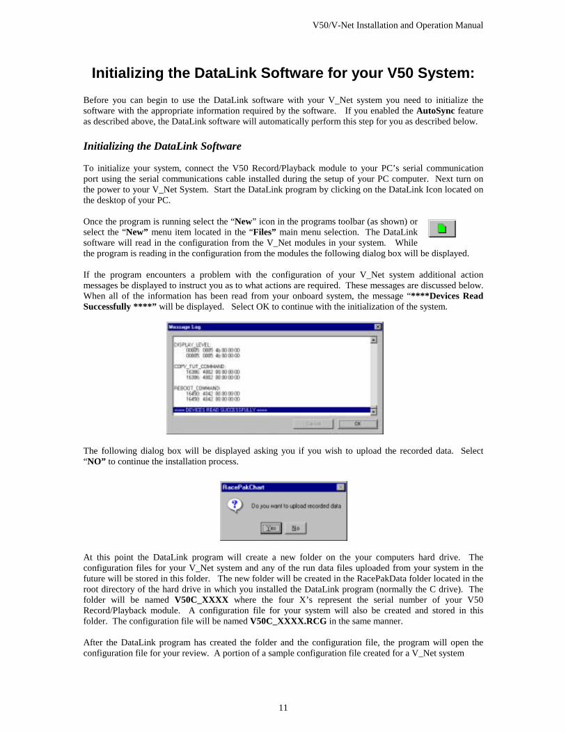
Initializing the DataLink Software for your V50 System: Before you can begin to use the DataLink software with your V_Net system you need to initialize the software with the appropriate information required by the software. If you enabled the AutoSync feature as described above, the DataLink software will automatically perform this step for you as described below. Initializing the DataLink Software To initialize your system, connect the V50 Record/Playback module to your PC’s serial communication port using the serial communications cable installed during the setup of your PC computer. Next turn on the power to your V_Net System. Start the DataLink program by clicking on the DataLink Icon located on the desktop of your PC. Once the program is running select the “New” icon in the programs toolbar (as shown) or select the “New” menu item located in the “Files” main menu selection. The DataLink software will read in the configuration from the V_Net modules in your system. While the program is reading in the configuration from the modules the following dialog box will be displayed. If the program encounters a problem with the configuration of your V_Net system additional action messages be displayed to instruct you as to what actions are required. These messages are discussed below. When all of the information has been read from your onboard system, the message “****Devices Read Successfully ****” will be displayed. Select OK to continue with the initialization of the system.
The following dialog box will be displayed asking you if you wish to upload the recorded data. Select “NO” to continue the installation process.
At this point the DataLink program will create a new folder on the your computers hard drive. The configuration files for your V_Net system and any of the run data files uploaded from your system in the future will be stored in this folder. The new folder will be created in the RacePakData folder located in the root directory of the hard drive in which you installed the DataLink program (normally the C drive). The folder will be named V50C_XXXX where the four X’s represent the serial number of your V50 Record/Playback module. A configuration file for your system will also be created and stored in this folder. The configuration file will be named V50C_XXXX.RCG in the same manner. After the DataLink program has created the folder and the configuration file, the program will open the configuration file for your review. A portion of a sample configuration file created for a V_Net system
V50/V-Net Installation and Operation Manual
12
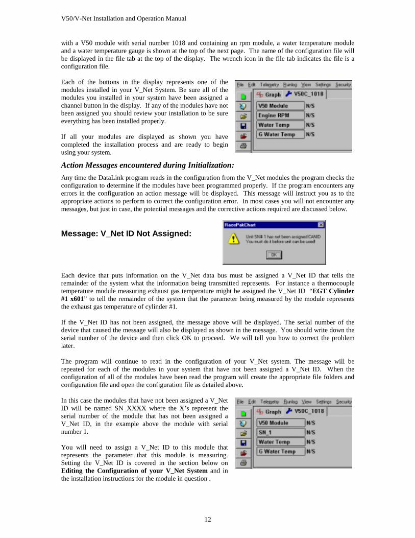
with a V50 module with serial number 1018 and containing an rpm module, a water temperature module and a water temperature gauge is shown at the top of the next page. The name of the configuration file will be displayed in the file tab at the top of the display. The wrench icon in the file tab indicates the file is a configuration file. Each of the buttons in the display represents one of the modules installed in your V_Net System. Be sure all of the modules you installed in your system have been assigned a channel button in the display. If any of the modules have not been assigned you should review your installation to be sure everything has been installed properly. If all your modules are displayed as shown you have completed the installation process and are ready to begin using your system.
Action Messages encountered during Initialization: Any time the DataLink program reads in the configuration from the V_Net modules the program checks the configuration to determine if the modules have been programmed properly. If the program encounters any errors in the configuration an action message will be displayed. This message will instruct you as to the appropriate actions to perform to correct the configuration error. In most cases you will not encounter any messages, but just in case, the potential messages and the corrective actions required are discussed below.
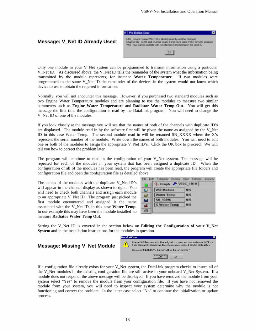
Message: V_Net ID Not Assigned: Each device that puts information on the V_Net data bus must be assigned a V_Net ID that tells the remainder of the system what the information being transmitted represents. For instance a thermocouple temperature module measuring exhaust gas temperature might be assigned the V_Net ID “EGT Cylinder #1 x601” to tell the remainder of the system that the parameter being measured by the module represents the exhaust gas temperature of cylinder #1. If the V_Net ID has not been assigned, the message above will be displayed. The serial number of the device that caused the message will also be displayed as shown in the message. You should write down the serial number of the device and then click OK to proceed. We will tell you how to correct the problem later. The program will continue to read in the configuration of your V_Net system. The message will be repeated for each of the modules in your system that have not been assigned a V_Net ID. When the configuration of all of the modules have been read the program will create the appropriate file folders and configuration file and open the configuration file as detailed above. In this case the modules that have not been assigned a V_Net ID will be named SN_XXXX where the X’s represent the serial number of the module that has not been assigned a V_Net ID, in the example above the module with serial number 1. You will need to assign a V_Net ID to this module that represents the parameter that this module is measuring. Setting the V_Net ID is covered in the section below on Editing the Configuration of your V_Net System and in the installation instructions for the module in question .
V50/V-Net Installation and Operation Manual
13
Message: V_Net ID Already Used: Only one module in your V_Net system can be programmed to transmit information using a particular V_Net ID. As discussed above, the V_Net ID tells the remainder of the system what the information being transmitted by the module represents, for instance Water Temperature. If two modules were programmed to the same V_Net ID the remainder of the devices in the system would not know which device to use to obtain the required information. Normally, you will not encounter this message. However, if you purchased two standard modules such as two Engine Water Temperature modules and are planning to use the modules to measure two similar parameters such as Engine Water Temperature and Radiator Water Temp Out. You will get this message the first time the configuration is read by the DataLink program. You will need to change the V_Net ID of one of the modules. If you look closely at the message you will see that the names of both of the channels with duplicate ID’s are displayed. The module read in by the software first will be given the name as assigned by the V_Net ID in this case Water Temp. The second module read in will be renamed SN_XXXX where the X’s represent the serial number of the module. Write down the names of both modules. You will need to edit one or both of the modules to assign the appropriate V_Net ID’s. Click the OK box to proceed. We will tell you how to correct the problem later. The program will continue to read in the configuration of your V_Net system. The message will be repeated for each of the modules in your system that has been assigned a duplicate ID. When the configuration of all of the modules has been read, the program will create the appropriate file folders and configuration file and open the configuration file as detailed above. The names of the modules with the duplicate V_Net ID’s will appear in the channel display as shown to right. You will need to check both channels and assign each module to an appropriate V_Net ID. The program just picked the first module encountered and assigned it the name associated with the V_Net ID, in this case Water Temp. In our example this may have been the module installed to measure Radiator Water Temp Out. Setting the V_Net ID is covered in the section below on Editing the Configuration of your V_Net System and in the installation instructions for the modules in question.
Message: Missing V_Net Module If a configuration file already exists for your V_Net system, the DataLink program checks to insure all of the V_Net modules in the existing configuration file are still active in your onboard V_Net System. If a module does not respond, the above message will be displayed. If you have removed the module from your system select “Yes” to remove the module from your configuration file. If you have not removed the module from your system, you will need to inspect your system determine why the module is not functioning and correct the problem. In the latter case select “No” to continue the initialization or update process.

V50/V-Net Installation and Operation Manual
15
Editing the Configuration of your V_Net System: In the step above the DataLink program created a configuration file for your V_Net System. In this section you will use this file to edit the setup of the various modules in your V_Net System. If the configuration file created above is still open select it for editing by left clicking on the file tab for the file. If your configuration file is not open you will need to open it before you can edit the setup of your V_Net system. If you can connect your PC to your V50 unit, repeat the process described above to open your configuration file. When opened in this manner the DataLink software will automatically update the configuration file on your PC to match the configuration of your onboard system.
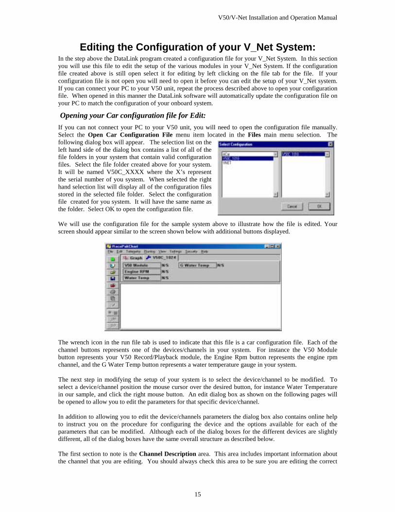
Opening your Car configuration file for Edit: If you can not connect your PC to your V50 unit, you will need to open the configuration file manually. Select the Open Car Configuration File menu item located in the Files main menu selection. The following dialog box will appear. The selection list on the left hand side of the dialog box contains a list of all of the file folders in your system that contain valid configuration files. Select the file folder created above for your system. It will be named V50C_XXXX where the X’s represent the serial number of you system. When selected the right hand selection list will display all of the configuration files stored in the selected file folder. Select the configuration file created for you system. It will have the same name as the folder. Select OK to open the configuration file. We will use the configuration file for the sample system above to illustrate how the file is edited. Your screen should appear similar to the screen shown below with additional buttons displayed.
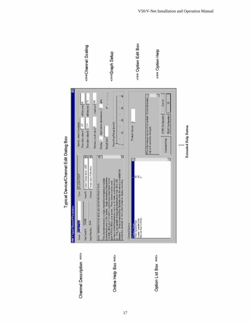
The wrench icon in the run file tab is used to indicate that this file is a car configuration file. Each of the channel buttons represents one of the devices/channels in your system. For instance the V50 Module button represents your V50 Record/Playback module, the Engine Rpm button represents the engine rpm channel, and the G Water Temp button represents a water temperature gauge in your system. The next step in modifying the setup of your system is to select the device/channel to be modified. To select a device/channel position the mouse cursor over the desired button, for instance Water Temperature in our sample, and click the right mouse button. An edit dialog box as shown on the following pages will be opened to allow you to edit the parameters for that specific device/channel. In addition to allowing you to edit the device/channels parameters the dialog box also contains online help to instruct you on the procedure for configuring the device and the options available for each of the parameters that can be modified. Although each of the dialog boxes for the different devices are slightly different, all of the dialog boxes have the same overall structure as described below. The first section to note is the Channel Description area. This area includes important information about the channel that you are editing. You should always check this area to be sure you are editing the correct
V50/V-Net Installation and Operation Manual
16
channel. When you are sure you are editing the proper channel go to the Online Help Scroll Box. Read this section. It will give you step by step instructions on configuring the specific device/channel you are editing. The following two pages describe the basic sections of the edit dialog box and their locations. Channel Description Area The channel description area contains several fields that describe the channel that is represented by the button and the edit dialog box. The fields in order of importance are as follows:
Type: The type field describes the type of device being edited, for instance a Logger_Analog input or an Oil Pressure Gauge
Unit Serial #: This field displays the serial number of the device being edited. Input Number: In devices such as a four-channel EGT module this field displays the channel
number in the device being edited. V_Net ID: The box displays the ID of the parameter measured by this device i.e. Drive Shaft Rpm Sensor Type: This field indicates the type of sensor connected to the channel Name: This is the user assigned name for the channel
Online Help Box The online help box is a scrollable text area containing detailed instructions on how to configure this device. You should always read this section before editing any of the device parameters.
Channel Scaling This section is used to enter the calibration factors for the sensor connected to this channel. These factors are entered automatically by the system any time the Sensor type is selected. They must be entered manually only when a custom sensor calibration is required.
Graph Setup These fields are used to define how the DataLink program charts the data obtained by this channel. Please refer to the online help box for details.
Options List Box The options list box displays all of the user settable options for the device being programmed. To select an option to be edited, place the mouse cursor over the desired option and click the left mouse button. The options help box and the options edit box will be updated with appropriate information for the selected option.
Options Help Box The options help box displays detailed information on the option currently selected for editing.
Options Edit Box The option edit box will display an appropriate edit box for the option currently selected in the options list. The edit box will display the name of the option being edited, the current value of the option, and the range of values that can be entered for the option if appropriate. Enter the new value for the option here. Extended Help Button If this button is present, extended help is available for this module type. To access the extended help simply position the mouse cursor over the button and click the left mouse button. The appropriate file viewer and the extended help file will be loaded for your review.
V50/V-Net Installation and Operation Manual
17
V50/V-Net Installation and Operation Manual
18
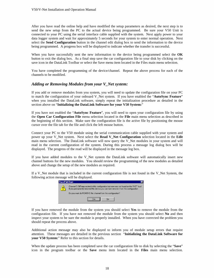
After you have read the online help and have modified the setup parameters as desired, the next step is to send the new setup from the PC to the actual device being programmed. Be sure your V50 Unit is connected to your PC using the serial interface cable supplied with the system. Next apply power to your data logger system and wait for approximately 5 seconds for your system to enter normal operation. Next select the Send Configuration button in the channel edit dialog box to send the information to the device being programmed. A progress box will be displayed to indicate whether the transfer is successful. When you have successfully sent the new information to the device being programmed select the OK button to exit the dialog box. As a final step save the car configuration file to your disk by clicking on the save icon in the DataLink Toolbar or select the Save menu item located in the Files main menu selection. You have completed the programming of the device/channel. Repeat the above process for each of the channels to be modified. Adding or Removing Modules from your V_Net system: If you add or remove modules from you system, you will need to update the configuration file on your PC to match the configuration of your onboard V_Net system. If you have enabled the “AutoSync Feature” when you installed the DataLink software, simply repeat the initialization procedure as detailed in the section above on “Initializing the DataLink Software for your V50 System:” If you have not enabled the “AutoSync Feature”, you will need to open your configuration file by using the Open Car Configuration File menu selection located in the File main menu selection as described in the beginning of this section. Make sure the configuration file is the active file by positioning the mouse cursor over the file tab for the file and click the left mouse button. Connect your PC to the V50 module using the serial communication cable supplied with your system and power up your V_Net system. Next select the Read V_Net Configuration selection located in the Edit main menu selection. The DataLink software will now query the V_Net modules in your system and will read in the current configuration of the system. During this process a message log dialog box will be displayed. The progress of the read will be displayed in the message log box. If you have added modules to the V_Net system the DataLink software will automatically insert new channel buttons for the new modules. You should review the programming of the new modules as detailed above and change the setup of the new modules as required. If a V_Net module that is included in the current configuration file is not found in the V_Net System, the following action message will be displayed.
If you have removed the module from the system you should select Yes to remove the module from the configuration file. If you have not removed the module from the system you should select No and then inspect your system to be sure the module is properly installed. When you have corrected the problem you should repeat the process above. Additional action message may also be displayed to inform you of module setup errors that require attention. These messages are detailed in the previous section “Initializing the DataLink Software for your V50 System:” Refer to this section for details. When the update process has been completed save the car configuration file to disk by selecting the “Save” icon in the program toolbar or the Save menu item located in the Files main menu selection.
V50/V-Net Installation and Operation Manual
19
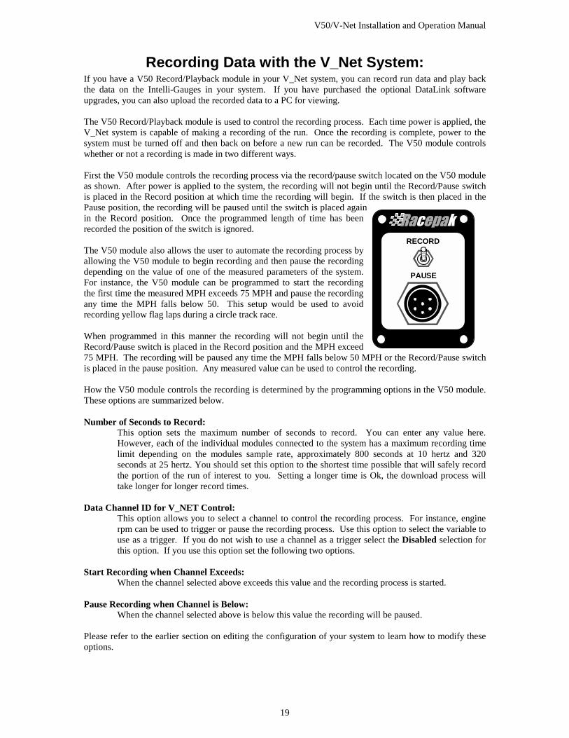
Recording Data with the V_Net System: If you have a V50 Record/Playback module in your V_Net system, you can record run data and play back the data on the Intelli-Gauges in your system. If you have purchased the optional DataLink software upgrades, you can also upload the recorded data to a PC for viewing. The V50 Record/Playback module is used to control the recording process. Each time power is applied, the V_Net system is capable of making a recording of the run. Once the recording is complete, power to the system must be turned off and then back on before a new run can be recorded. The V50 module controls whether or not a recording is made in two different ways. First the V50 module controls the recording process via the record/pause switch located on the V50 module as shown. After power is applied to the system, the recording will not begin until the Record/Pause switch is placed in the Record position at which time the recording will begin. If the switch is then placed in the Pause position, the recording will be paused until the switch is placed again in the Record position. Once the programmed length of time has been recorded the position of the switch is ignored. The V50 module also allows the user to automate the recording process by allowing the V50 module to begin recording and then pause the recording depending on the value of one of the measured parameters of the system. For instance, the V50 module can be programmed to start the recording the first time the measured MPH exceeds 75 MPH and pause the recording any time the MPH falls below 50. This setup would be used to avoid recording yellow flag laps during a circle track race. When programmed in this manner the recording will not begin until the Record/Pause switch is placed in the Record position and the MPH exceed 75 MPH. The recording will be paused any time the MPH falls below 50 MPH or the Record/Pause switch is placed in the pause position. Any measured value can be used to control the recording. How the V50 module controls the recording is determined by the programming options in the V50 module. These options are summarized below. Number of Seconds to Record:
This option sets the maximum number of seconds to record. You can enter any value here. However, each of the individual modules connected to the system has a maximum recording time limit depending on the modules sample rate, approximately 800 seconds at 10 hertz and 320 seconds at 25 hertz. You should set this option to the shortest time possible that will safely record the portion of the run of interest to you. Setting a longer time is Ok, the download process will take longer for longer record times.
Data Channel ID for V_NET Control:
This option allows you to select a channel to control the recording process. For instance, engine rpm can be used to trigger or pause the recording process. Use this option to select the variable to use as a trigger. If you do not wish to use a channel as a trigger select the Disabled selection for this option. If you use this option set the following two options.
Start Recording when Channel Exceeds: When the channel selected above exceeds this value and the recording process is started. Pause Recording when Channel is Below: When the channel selected above is below this value the recording will be paused. Please refer to the earlier section on editing the configuration of your system to learn how to modify these options.
RECORD
PAUSE

V50/V-Net Installation and Operation Manual
21
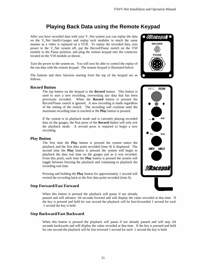
Playing Back Data using the Remote Keypad After you have recorded data with your V_Net system you can replay the data on the V_Net Intelli-Gauges and replay tach modules in much the same manner as a video is replayed on a VCR. To replay the recorded data, turn power to the V_Net system off, put the Record/Pause switch on the V50 module in the Pause position, and plug the remote keypad into the connector located on the V50 module as shown . Turn the power to the system on. You will now be able to control the replay of the run data with the remote keypad. The remote keypad is illustrated below. The buttons and their function starting from the top of the keypad are as follows. Record Button
The top button on the keypad is the Record button. This button is used to start a new recording, overwriting any data that has been previously recorded. When the Record button is pressed the Record/Pause switch is ignored. A new recording is made regardless of the setting of the switch. The recording will continue until the maximum recording time is reached or the Play button is pressed. If the system is in playback mode and is currently playing recorded data on the gauges, the first press of the Record button will only exit the playback mode. A second press is required to begin a new recording.
Play Button The first time the Play button is pressed the system enters the playback and the first data point recorded (time 0) is displayed. The second time the Play button is pressed the system will begin to playback the data real time on the gauges just as it was recorded. From this point, each time the Play button is pressed the system will toggle between freezing the playback and continuing to playback the recording real time. Pressing and holding the Play button for approximately 1 second will rewind the recording back to the first data point recorded (time 0).
Step Forward/Fast Forward
When this button is pressed the playback will pause if not already paused and will advance .04 seconds forward and will display the value recorded at that time. If the key is pressed and held for one second the playback will be fast-forwarded 1 second for each .1 second the key is held.
Step Backward/Fast Backward
When this button is pressed the playback will pause if not already paused and will step .04 seconds backwards and will display the value recorded at that time. If the key is pressed and held for one second the playback will be fast reversed 1 second for each .1 second the key is held.
RECORD
PAUSE
V50/V-Net Installation and Operation Manual
22
Min/Max/Tag Key When this button is first pressed, the system will be instructed to display the minimum value reading the gauges have received. The next press will instruct the system to display the maximum value reading received by the gauges. The third press will instruct the system to display the TAG values on the digital readout on the gauges. The min and max values are not the min and max values from the recorded data but rather the min and max values since the system was powered. Pressing and holding this button for approximately 1 second will reset the min and max values. If the button is not pressed for approximately 1 minute the system will revert to displaying real time values.
V50/V-Net Installation and Operation Manual
23
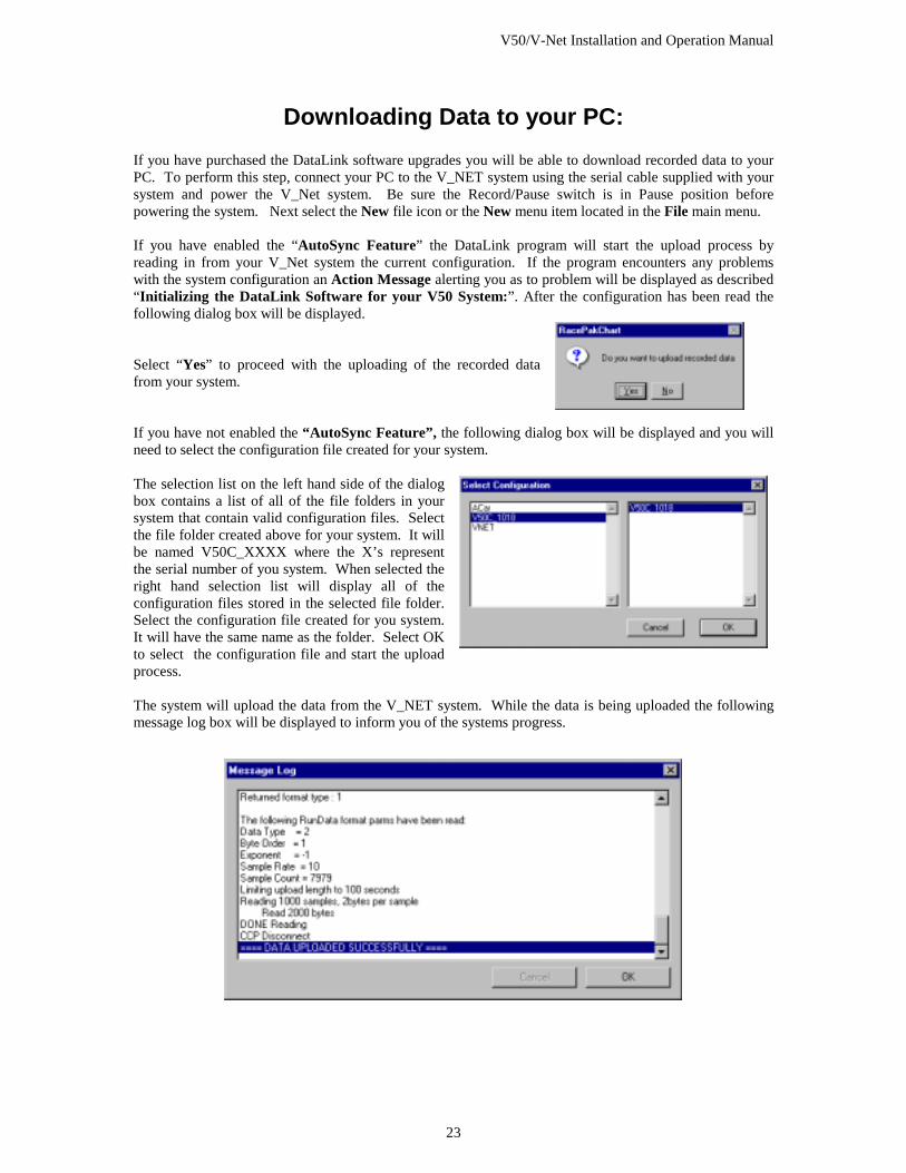
Downloading Data to your PC: If you have purchased the DataLink software upgrades you will be able to download recorded data to your PC. To perform this step, connect your PC to the V_NET system using the serial cable supplied with your system and power the V_Net system. Be sure the Record/Pause switch is in Pause position before powering the system. Next select the New file icon or the New menu item located in the File main menu. If you have enabled the “AutoSync Feature” the DataLink program will start the upload process by reading in from your V_Net system the current configuration. If the program encounters any problems with the system configuration an Action Message alerting you as to problem will be displayed as described “Initializing the DataLink Software for your V50 System:”. After the configuration has been read the following dialog box will be displayed. Select “Yes” to proceed with the uploading of the recorded data from your system. If you have not enabled the “AutoSync Feature”, the following dialog box will be displayed and you will need to select the configuration file created for your system. The selection list on the left hand side of the dialog box contains a list of all of the file folders in your system that contain valid configuration files. Select the file folder created above for your system. It will be named V50C_XXXX where the X’s represent the serial number of you system. When selected the right hand selection list will display all of the configuration files stored in the selected file folder. Select the configuration file created for you system. It will have the same name as the folder. Select OK to select the configuration file and start the upload process. The system will upload the data from the V_NET system. While the data is being uploaded the following message log box will be displayed to inform you of the systems progress.
V50/V-Net Installation and Operation Manual
24
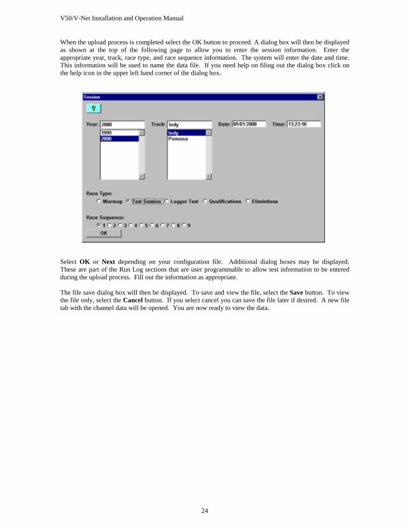
When the upload process is completed select the OK button to proceed. A dialog box will then be displayed as shown at the top of the following page to allow you to enter the session information. Enter the appropriate year, track, race type, and race sequence information. The system will enter the date and time. This information will be used to name the data file. If you need help on filing out the dialog box click on the help icon in the upper left hand corner of the dialog box.
Select OK or Next depending on your configuration file. Additional dialog boxes may be displayed. These are part of the Run Log sections that are user programmable to allow test information to be entered during the upload process. Fill out the information as appropriate. The file save dialog box will then be displayed. To save and view the file, select the Save button. To view the file only, select the Cancel button. If you select cancel you can save the file later if desired. A new file tab with the channel data will be opened. You are now ready to view the data.
V50/V-Net Installation and Operation Manual
25
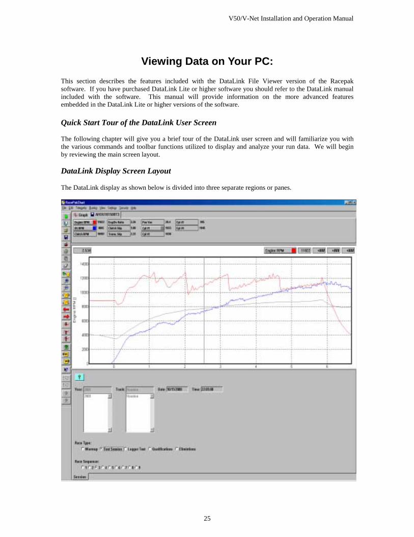
Viewing Data on Your PC: This section describes the features included with the DataLink File Viewer version of the Racepak software. If you have purchased DataLink Lite or higher software you should refer to the DataLink manual included with the software. This manual will provide information on the more advanced features embedded in the DataLink Lite or higher versions of the software. Quick Start Tour of the DataLink User Screen The following chapter will give you a brief tour of the DataLink user screen and will familiarize you with the various commands and toolbar functions utilized to display and analyze your run data. We will begin by reviewing the main screen layout. DataLink Display Screen Layout The DataLink display as shown below is divided into three separate regions or panes.
V50/V-Net Installation and Operation Manual
26
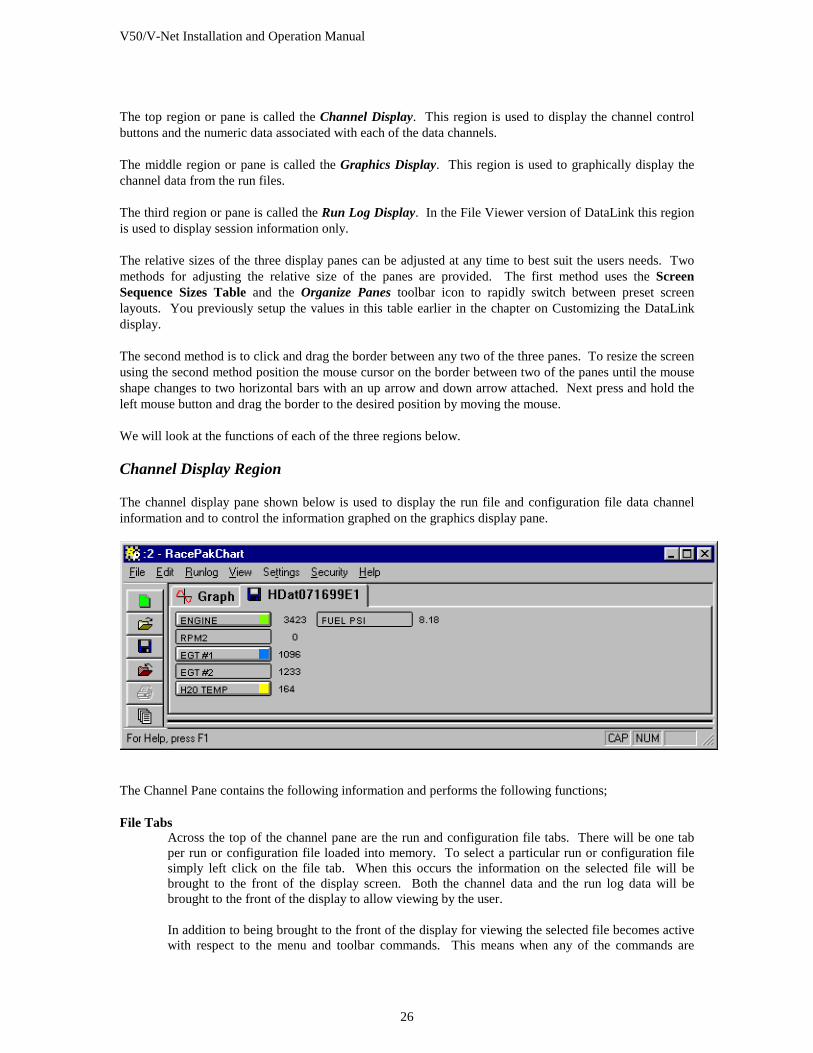
The top region or pane is called the Channel Display. This region is used to display the channel control buttons and the numeric data associated with each of the data channels. The middle region or pane is called the Graphics Display. This region is used to graphically display the channel data from the run files. The third region or pane is called the Run Log Display. In the File Viewer version of DataLink this region is used to display session information only. The relative sizes of the three display panes can be adjusted at any time to best suit the users needs. Two methods for adjusting the relative size of the panes are provided. The first method uses the Screen Sequence Sizes Table and the Organize Panes toolbar icon to rapidly switch between preset screen layouts. You previously setup the values in this table earlier in the chapter on Customizing the DataLink display. The second method is to click and drag the border between any two of the three panes. To resize the screen using the second method position the mouse cursor on the border between two of the panes until the mouse shape changes to two horizontal bars with an up arrow and down arrow attached. Next press and hold the left mouse button and drag the border to the desired position by moving the mouse. We will look at the functions of each of the three regions below. Channel Display Region The channel display pane shown below is used to display the run file and configuration file data channel information and to control the information graphed on the graphics display pane.
The Channel Pane contains the following information and performs the following functions; File Tabs
Across the top of the channel pane are the run and configuration file tabs. There will be one tab per run or configuration file loaded into memory. To select a particular run or configuration file simply left click on the file tab. When this occurs the information on the selected file will be brought to the front of the display screen. Both the channel data and the run log data will be brought to the front of the display to allow viewing by the user. In addition to being brought to the front of the display for viewing the selected file becomes active with respect to the menu and toolbar commands. This means when any of the commands are
V50/V-Net Installation and Operation Manual
27
executed, such as the set start command, the commands will operate on the selected file. Commands and menu items that are not appropriate for the selected file are grayed to show they are inactive. Each file tab contains an icon to indicate the type of file. A floppy disc icon indicates the file is a run data file containing the data from the on board recorder. A wrench icon indicates the file is a car configuration file and contains setup data for the car and onboard recorder. The left most tab, the Graph tab, is used to summarize the graphed channels such that the numeric data of all graphed channels can be displayed on one screen. The run file name and graphed data channels are displayed side by side.
Channel Buttons Directly under the File Tabs are the channel buttons. Each channel button represents a data channel, such as ENGINE RPM, stored in the run file. The buttons are used to control the graphing of the channel information. Left clicking on the channel button displays that channel on the graphics display. When the channel is enabled a small square will appear in the channel button indicating the color being used to graph the channel. A second left click on the channel disables the graphing of the channel. Right clicking on the channel button brings up the appropriate Easy Edit dialog box used to modify the setup of the channel. The Easy Edits are discussed in detail in the chapter called Working with Data Channels.
Numeric Data Display Directly to the right of the channel button is the channel numeric data display. This display shows the value of the channel at the current Cursor Time position. The cursor position and the associated time is discussed below.
Channel Region Scroll Bar If the channel pane is too small to display the entire group of channel buttons at the same time a scroll bar will appear at the bottom of the channel pane. The scroll bar can be used to select the portion of the channel pane displayed at any given time.
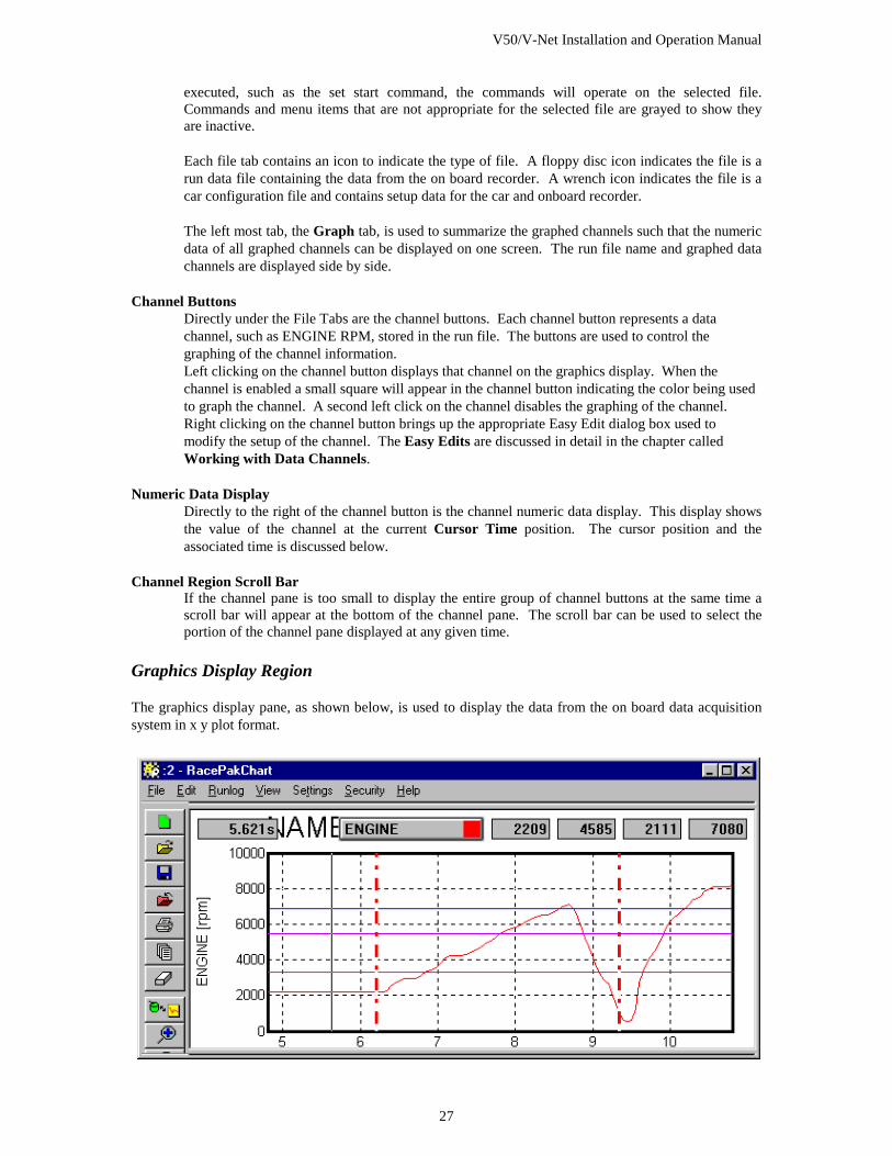
Graphics Display Region The graphics display pane, as shown below, is used to display the data from the on board data acquisition system in x y plot format.
V50/V-Net Installation and Operation Manual
28
The graphics display pane is composed of the following items:
X Y Plot Region The x y plot region is the area on the screen that is used to plot the graphics information. This area is composed of the following elements
X-axis The x axis or horizontal axis is used to represent the time axis. The start of the run is represented as 0 time. Time into the run increases from left to right on the x-axis.
Vertical Grid The vertical grid shown as light dotted lines from the bottom of the graph to the top correspond to the time axis. Each point on the grid line is equal time into the run.
Y-axis The y-axis or vertical axis is used to represent the value of the data being displayed. Data values increase from bottom to top in the graph
Horizontal Grid The horizontal grid shown as light dotted lines moving from left to right on the x y plot are points of constant value for the data.
Data Grid Legend The data grid legend is displayed on the left-hand side of the x y plot. The data grid is used to show the value of the horizontal grid lines for the data channel selected as the channel grid. The name of the selected channel and the engineering units displayed are also shown on the left-hand side of the graph.
Time Cursor The time cursor is shown as a solid line from the bottom to the top of the plot region. The time cursor is used to indicate the point in the run currently being displayed in the numeric displays and in the time dependent data fields in the run log displays. To move the time cursor to a new time position, use one of the following methods. Computer Mouse
Position the mouse cursor at the desired point on the x y plot region and click the left mouse button. The time cursor line will move to the new position and the data values will be updated on the screen. The DataLink software also features ‘mouse tracking’. This feature allows you to click and hold the left mouse button. When the mouse is moved, the time cursor will follow the mouse pointer and the data values will be updated accordingly.
Left Arrow Key Press the left arrow key to move the time cursor one increment earlier in the run.
Right Arrow Key Press the right arrow key to move the time cursor one increment later in the run.
Up Arrow Key Press the up arrow key to move the time cursor ten time increments later in the run.
Down Arrow Key Press the down arrow key to move the time cursor tem time increments earlier in the run.
V50/V-Net Installation and Operation Manual
29
Cursor Time Display The cursor time display, located in the upper left-hand corner of the graphics display region, shows the time into the run from the start time marker to the current time cursor position.
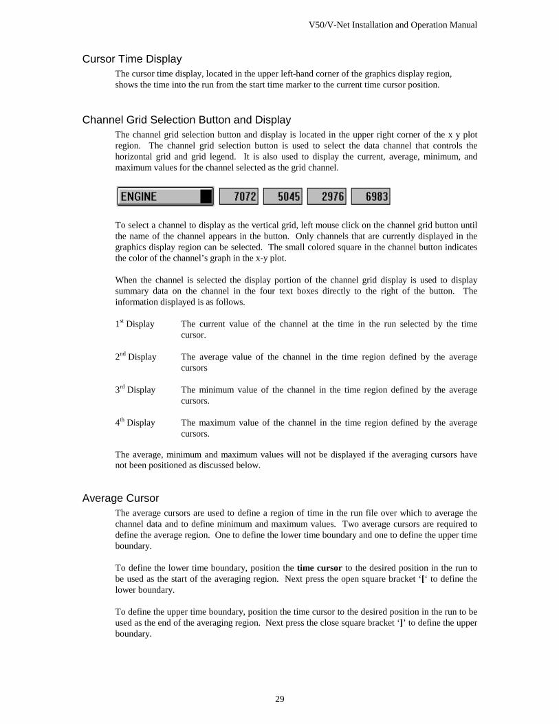
Channel Grid Selection Button and Display The channel grid selection button and display is located in the upper right corner of the x y plot region. The channel grid selection button is used to select the data channel that controls the horizontal grid and grid legend. It is also used to display the current, average, minimum, and maximum values for the channel selected as the grid channel.
To select a channel to display as the vertical grid, left mouse click on the channel grid button until the name of the channel appears in the button. Only channels that are currently displayed in the graphics display region can be selected. The small colored square in the channel button indicates the color of the channel’s graph in the x-y plot. When the channel is selected the display portion of the channel grid display is used to display summary data on the channel in the four text boxes directly to the right of the button. The information displayed is as follows. 1st Display The current value of the channel at the time in the run selected by the time
cursor. 2nd Display The average value of the channel in the time region defined by the average
cursors 3rd Display The minimum value of the channel in the time region defined by the average
cursors. 4th Display The maximum value of the channel in the time region defined by the average
cursors. The average, minimum and maximum values will not be displayed if the averaging cursors have not been positioned as discussed below.
Average Cursor The average cursors are used to define a region of time in the run file over which to average the channel data and to define minimum and maximum values. Two average cursors are required to define the average region. One to define the lower time boundary and one to define the upper time boundary. To define the lower time boundary, position the time cursor to the desired position in the run to be used as the start of the averaging region. Next press the open square bracket ‘[‘ to define the lower boundary. To define the upper time boundary, position the time cursor to the desired position in the run to be used as the end of the averaging region. Next press the close square bracket ‘]’ to define the upper boundary.
V50/V-Net Installation and Operation Manual
30
The average, minimum, and maximum values will now be displayed on the channel grid display for the data channel selected.
To remove the average cursors press the ‘[‘ and ‘]’ at the same cursor location. The average cursors will be removed
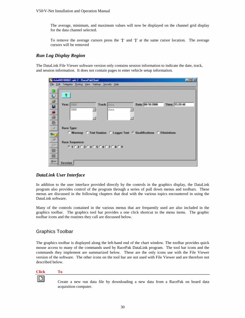
Run Log Display Region The DataLink File Viewer software version only contains session information to indicate the date, track, and session information. It does not contain pages to enter vehicle setup information.
DataLink User Interface In addition to the user interface provided directly by the controls in the graphics display, the DataLink program also provides control of the program through a series of pull down menus and toolbars. These menus are discussed in the following chapters that deal with the various topics encountered in using the DataLink software. Many of the controls contained in the various menus that are frequently used are also included in the graphics toolbar. The graphics tool bar provides a one click shortcut to the menu items. The graphic toolbar icons and the routines they call are discussed below.
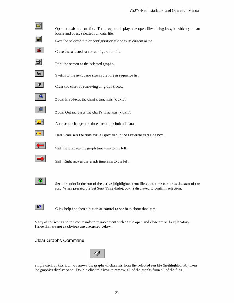
Graphics Toolbar The graphics toolbar is displayed along the left-hand end of the chart window. The toolbar provides quick mouse access to many of the commands used by RacePak DataLink program. The tool bar icons and the commands they implement are summarized below. These are the only icons use with the File Viewer version of the software. The other icons on the tool bar are not used with File Viewer and are therefore not described below.
Click To
Create a new run data file by downloading a new data from a RacePak on board data acquisition computer.
V50/V-Net Installation and Operation Manual
31
Open an existing run file. The program displays the open files dialog box, in which you can locate and open, selected run data file.
Save the selected run or configuration file with its current name.
Close the selected run or configuration file.
Print the screen or the selected graphs.
Switch to the next pane size in the screen sequence list.
Clear the chart by removing all graph traces.
Zoom In reduces the chart’s time axis (x-axis).
Zoom Out increases the chart’s time axis (x-axis).
Auto scale changes the time axes to include all data.
User Scale sets the time axis as specified in the Preferences dialog box.
Shift Left moves the graph time axis to the left.
Shift Right moves the graph time axis to the left.
Sets the point in the run of the active (highlighted) run file at the time cursor as the start of the run. When pressed the Set Start Time dialog box is displayed to confirm selection.
Click help and then a button or control to see help about that item. Many of the icons and the commands they implement such as file open and close are self-explanatory. Those that are not as obvious are discussed below.
Clear Graphs Command
Single click on this icon to remove the graphs of channels from the selected run file (highlighted tab) from the graphics display pane. Double click this icon to remove all of the graphs from all of the files.
V50/V-Net Installation and Operation Manual
32
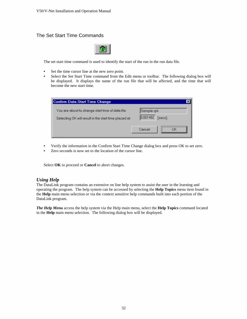
The Set Start Time Commands
The set start time command is used to identify the start of the run in the run data file. • Set the time cursor line at the new zero point. • Select the Set Start Time command from the Edit menu or toolbar. The following dialog box will
be displayed. It displays the name of the run file that will be affected, and the time that will become the new start time.
• Verify the information in the Confirm Start Time Change dialog box and press OK to set zero. • Zero seconds is now set to the location of the cursor line.
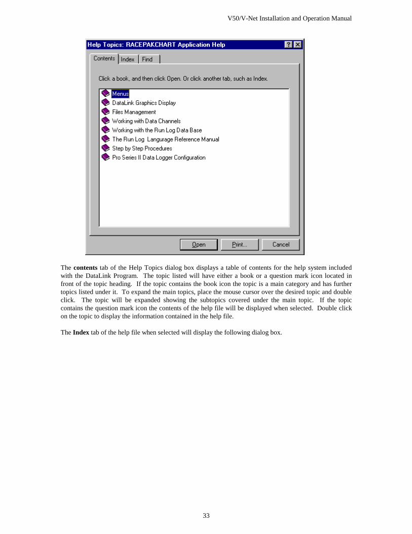
Select OK to proceed or Cancel to abort changes. Using Help The DataLink program contains an extensive on line help system to assist the user in the learning and operating the program. The help system can be accessed by selecting the Help Topics menu item found in the Help main menu selection or via the context sensitive help commands built into each portion of the DataLink program. The Help Menu access the help system via the Help main menu, select the Help Topics command located in the Help main menu selection. The following dialog box will be displayed.
V50/V-Net Installation and Operation Manual
33
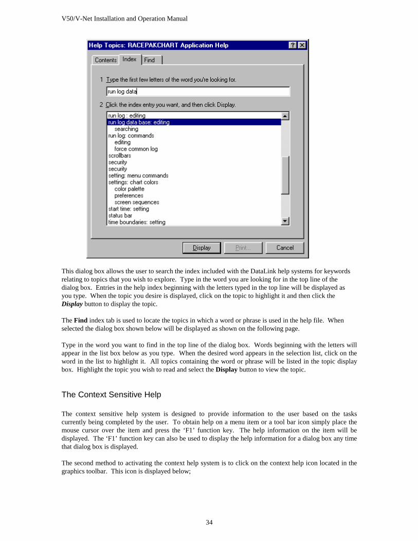
The contents tab of the Help Topics dialog box displays a table of contents for the help system included with the DataLink Program. The topic listed will have either a book or a question mark icon located in front of the topic heading. If the topic contains the book icon the topic is a main category and has further topics listed under it. To expand the main topics, place the mouse cursor over the desired topic and double click. The topic will be expanded showing the subtopics covered under the main topic. If the topic contains the question mark icon the contents of the help file will be displayed when selected. Double click on the topic to display the information contained in the help file. The Index tab of the help file when selected will display the following dialog box.
V50/V-Net Installation and Operation Manual
34
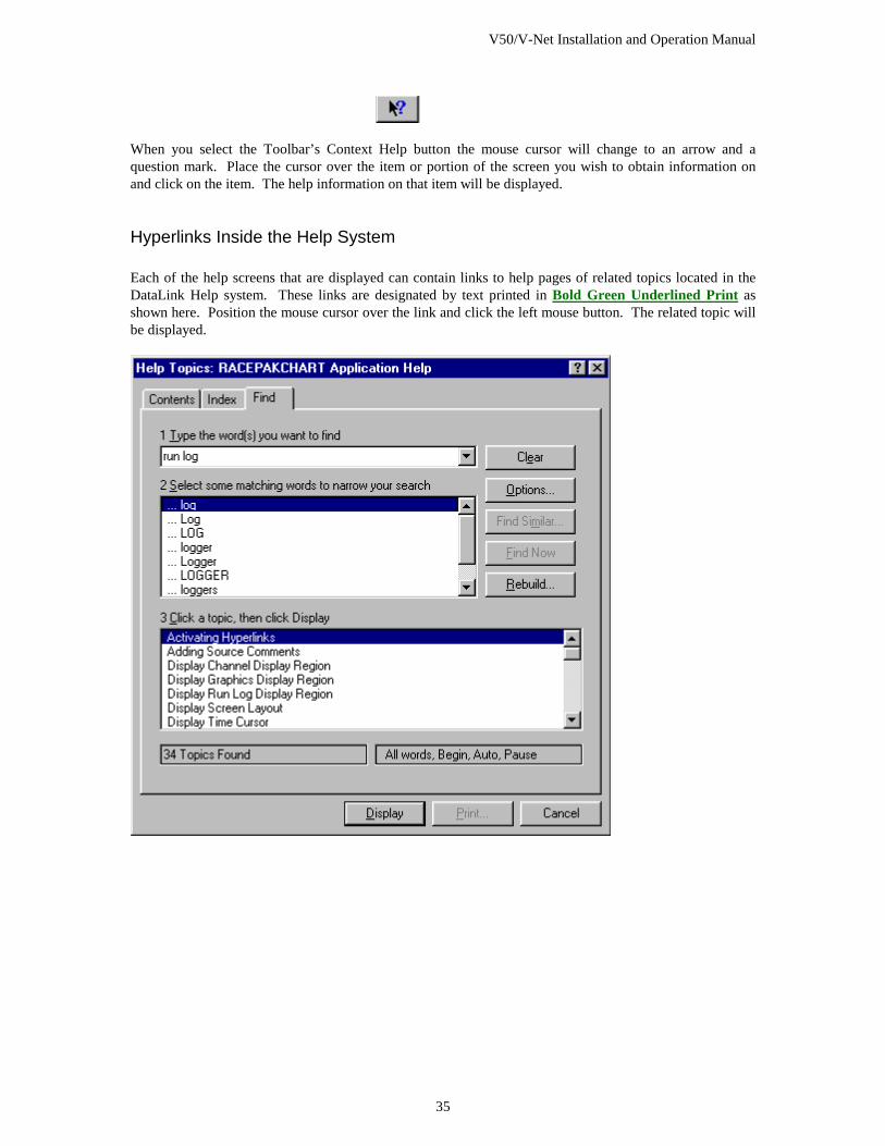
This dialog box allows the user to search the index included with the DataLink help systems for keywords relating to topics that you wish to explore. Type in the word you are looking for in the top line of the dialog box. Entries in the help index beginning with the letters typed in the top line will be displayed as you type. When the topic you desire is displayed, click on the topic to highlight it and then click the Display button to display the topic. The Find index tab is used to locate the topics in which a word or phrase is used in the help file. When selected the dialog box shown below will be displayed as shown on the following page. Type in the word you want to find in the top line of the dialog box. Words beginning with the letters will appear in the list box below as you type. When the desired word appears in the selection list, click on the word in the list to highlight it. All topics containing the word or phrase will be listed in the topic display box. Highlight the topic you wish to read and select the Display button to view the topic.
The Context Sensitive Help The context sensitive help system is designed to provide information to the user based on the tasks currently being completed by the user. To obtain help on a menu item or a tool bar icon simply place the mouse cursor over the item and press the ‘F1’ function key. The help information on the item will be displayed. The ‘F1’ function key can also be used to display the help information for a dialog box any time that dialog box is displayed. The second method to activating the context help system is to click on the context help icon located in the graphics toolbar. This icon is displayed below;
V50/V-Net Installation and Operation Manual
35
When you select the Toolbar’s Context Help button the mouse cursor will change to an arrow and a question mark. Place the cursor over the item or portion of the screen you wish to obtain information on and click on the item. The help information on that item will be displayed.
Hyperlinks Inside the Help System Each of the help screens that are displayed can contain links to help pages of related topics located in the DataLink Help system. These links are designated by text printed in Bold Green Underlined Print as shown here. Position the mouse cursor over the link and click the left mouse button. The related topic will be displayed.

V50/V-Net Installation and Operation Manual
37
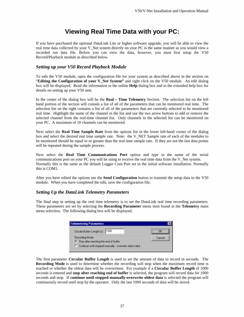
Viewing Real Time Data with your PC: If you have purchased the optional DataLink Lite or higher software upgrade, you will be able to view the real time data collected by your V_Net system directly on your PC is the same manner as you would view a recorded run data file. Before you can view the data, however, you must first setup the V50 Record/Playback module as described below. Setting up your V50 Record Playback Module To edit the V50 module, open the configuration file for your system as described above in the section on “Editing the Configuration of your V_Net System” and right click on the V50 module. An edit dialog box will be displayed. Read the information in the online Help dialog box and in the extended help box for details on setting up your V50 unit. In the center of the dialog box will be the Real – Time Telemetry Section. The selection list on the left hand portion of the section will contain a list of all of the parameters that can be monitored real time. The selection list on the right contains a list of all of the parameters that are currently selected to be monitored real time. Highlight the name of the channel in the list and use the two arrow buttons to add or remove the selected channel from the real-time channel list. Only channels in the selected list can be monitored on your PC. A maximum of 10 channels can be monitored. Next select the Real Time Sample Rate from the options list in the lower left-hand corner of the dialog box and select the desired real time sample rate. Note: the V_NET Sample rate of each of the modules to be monitored should be equal to or greater than the real time sample rate. If they are not the last data points will be repeated during the sample process. Next select the Real Time Communications Port option and type in the name of the serial communications port on your PC you will be using to receive the real time data from the V_Net system. Normally this is the same as the default Logger Com Port set in the initial software installation. Normally this is COM1. After you have edited the options use the Send Configuration button to transmit the setup data to the V50 module. When you have completed the edit, save the configuration file. Setting Up the DataLink Telemetry Parameters The final step in setting up the real time telemetry is to set the DataLink real time recording parameters. These parameters are set by selecting the Recording Parameter menu item found in the Telemetry main menu selection. The following dialog box will be displayed.
The first parameter Circular Buffer Length is used to set the amount of data to record in seconds. The Recording Mode is used to determine whether the recording will stop when the maximum record time is reached or whether the oldest data will be overwritten. For example if a Circular Buffer Length of 1000 seconds is entered and stop after reaching end of buffer is selected, the program will record data for 1000 seconds and stop. If continue until stopped manually-overwrite oldest data is selected the program will continuously record until stop by the operator. Only the last 1000 seconds of data will be stored.
V50/V-Net Installation and Operation Manual
38
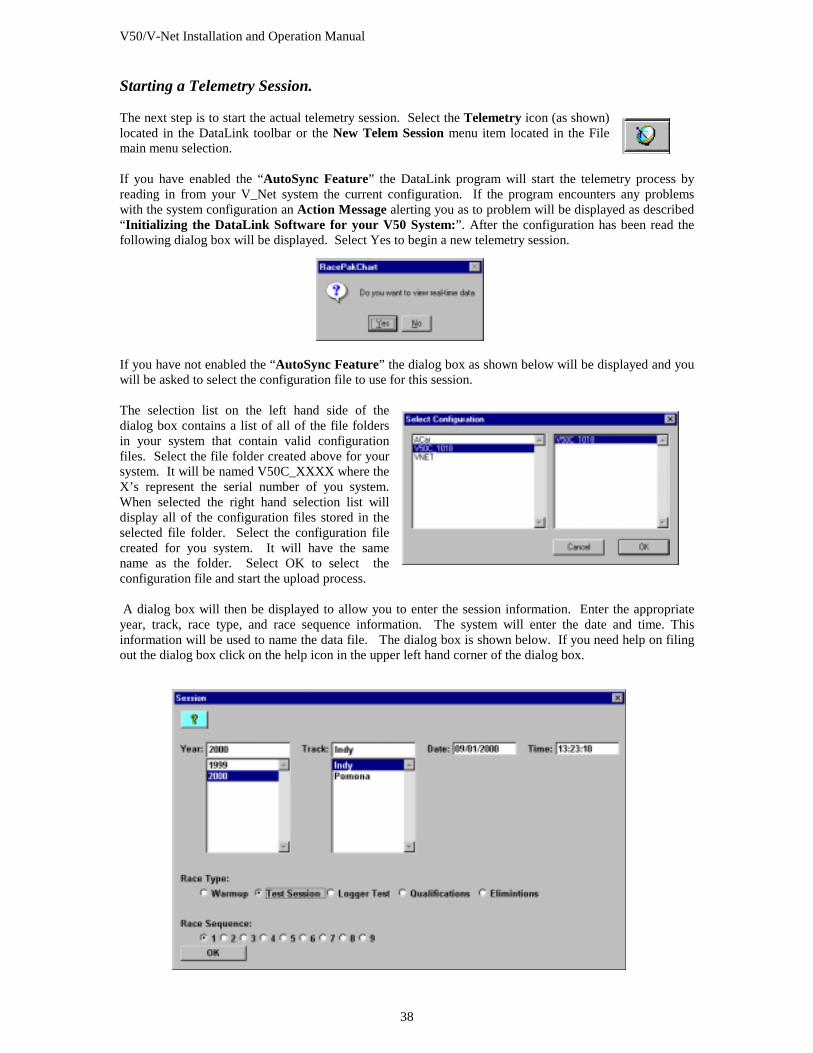
Starting a Telemetry Session. The next step is to start the actual telemetry session. Select the Telemetry icon (as shown) located in the DataLink toolbar or the New Telem Session menu item located in the File main menu selection. If you have enabled the “AutoSync Feature” the DataLink program will start the telemetry process by reading in from your V_Net system the current configuration. If the program encounters any problems with the system configuration an Action Message alerting you as to problem will be displayed as described “Initializing the DataLink Software for your V50 System:”. After the configuration has been read the following dialog box will be displayed. Select Yes to begin a new telemetry session.
If you have not enabled the “AutoSync Feature” the dialog box as shown below will be displayed and you will be asked to select the configuration file to use for this session. The selection list on the left hand side of the dialog box contains a list of all of the file folders in your system that contain valid configuration files. Select the file folder created above for your system. It will be named V50C_XXXX where the X’s represent the serial number of you system. When selected the right hand selection list will display all of the configuration files stored in the selected file folder. Select the configuration file created for you system. It will have the same name as the folder. Select OK to select the configuration file and start the upload process. A dialog box will then be displayed to allow you to enter the session information. Enter the appropriate year, track, race type, and race sequence information. The system will enter the date and time. This information will be used to name the data file. The dialog box is shown below. If you need help on filing out the dialog box click on the help icon in the upper left hand corner of the dialog box.
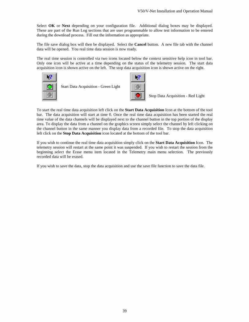
V50/V-Net Installation and Operation Manual
39
Select OK or Next depending on your configuration file. Additional dialog boxes may be displayed. These are part of the Run Log sections that are user programmable to allow test information to be entered during the download process. Fill out the information as appropriate. The file save dialog box will then be displayed. Select the Cancel button. A new file tab with the channel data will be opened. You real time data session is now ready. The real time session is controlled via two icons located below the context sensitive help icon in tool bar. Only one icon will be active at a time depending on the status of the telemetry session. The start data acquisition icon is shown active on the left. The stop data acquisition icon is shown active on the right.
Start Data Acquisition - Green Light Stop Data Acquisition - Red Light
To start the real time data acquisition left click on the Start Data Acquisition Icon at the bottom of the tool bar. The data acquisition will start at time 0. Once the real time data acquisition has been started the real time value of the data channels will be displayed next to the channel button in the top portion of the display area. To display the data from a channel on the graphics screen simply select the channel by left clicking on the channel button in the same manner you display data from a recorded file. To stop the data acquisition left click on the Stop Data Acquisition icon located at the bottom of the tool bar. If you wish to continue the real time data acquisition simply click on the Start Data Acquisition Icon. The telemetry session will restart at the same point it was suspended. If you wish to restart the session from the beginning select the Erase menu item located in the Telemetry main menu selection. The previously recorded data will be erased. If you wish to save the data, stop the data acquisition and use the save file function to save the data file.

V50/V-Net Installation and Operation Manual
41
Appendix V: V_Net Module Installation Instructions