woodworking plans - entertainment center
TRANSCRIPT
TM
page 1 of 12
DOWNLOADABLE PROJECT PLANS FROM THE EDITORS OF WOOD MAGAZINE http://www.woodmagazine.com
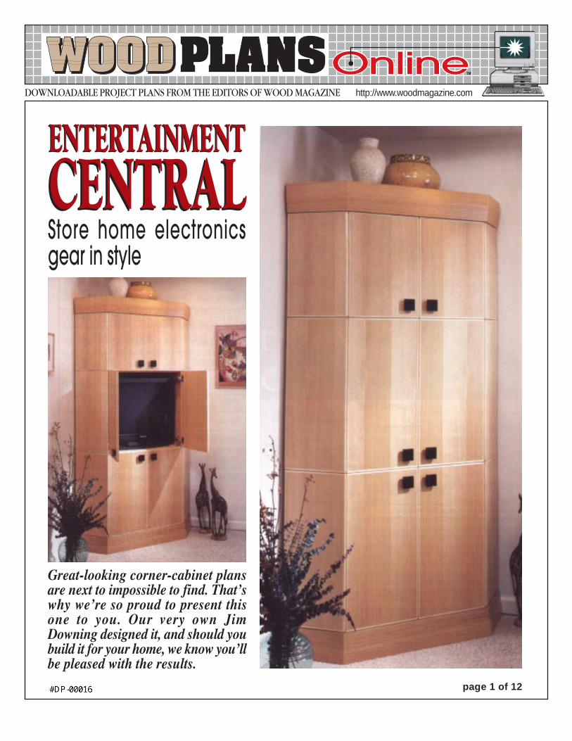
Great-looking corner-cabinet plansare next to impossible to find. That’swhy we’re so proud to present thisone to you. Our very own JimDowning designed it, and should youbuild it for your home, we know you’llbe pleased with the results.
ENTERTAINMENT
CENTRALStore home electronicsgear in style
ENTERTAINMENT
CENTRAL
TM
page 2 of 12
#8 x 11/4" F.H. wood screws
133/8"
7011/16"
213/16"
80"
3/4" notches13/4" deep
45O bevel
3/4 x 25/16" notches
5/32" holes, counter-sunk on bottom
3/4" dadoes1/4" deep
D
A
A
A
80"
A
3/4" notch13/4" deep
411/16"
253/16"
251/4"
171/4"
45/8"
#8 x 11/4" F.H. wood screws
CARCASE1/4" mounting holes (for mounting molding)
1/4" mounting holes(for mounting panels)
5/32" hole,countersunk
G
C
F
F
F
F
DD
FG
B
B
B
B
H
H
H
H#8 x 1" F.H. wood screw
H
H
H
#8 x 1" F.H. wood screw
#8 x 11/4" F.H. wood screws
#8 x 11/2" F.H.wood screws
1/4" holes1/2" deepfor shelfsupports
2 x 10" notchfor ventilation
F
E
C
4"
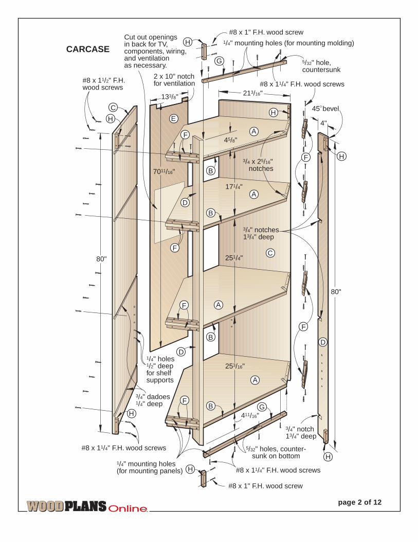
Cut out openingsin back for TV,components, wiring,and ventilationas necessary.
TM
page 3 of 12
1/2" rabbet1/2" deep
1/2" rabbet 1/4" deep
Rip 45o miters afterpanel is assembled.
1"
101/2"
SIDE PANEL(BACK VIEW)
1/4"
3/4" W
andO P
andS T
This edge will gonext to doors.
17/32"1"
1/2"1/4"
1/2"
and
MITER DETAIL (TOP VIEW)
andS
O
T
P
45o miters
1/4"
U Vand
1/2"
Miter end of cleat to 45O.
5/32" holes,countersunk
7/64" pilot hole 1/2" deep
3/4" dado 1/4" deep 45O bevel
#8 x 11/4" F.H. wood screws
AASSEMBLY
DETAILG
F
BF
HC
D
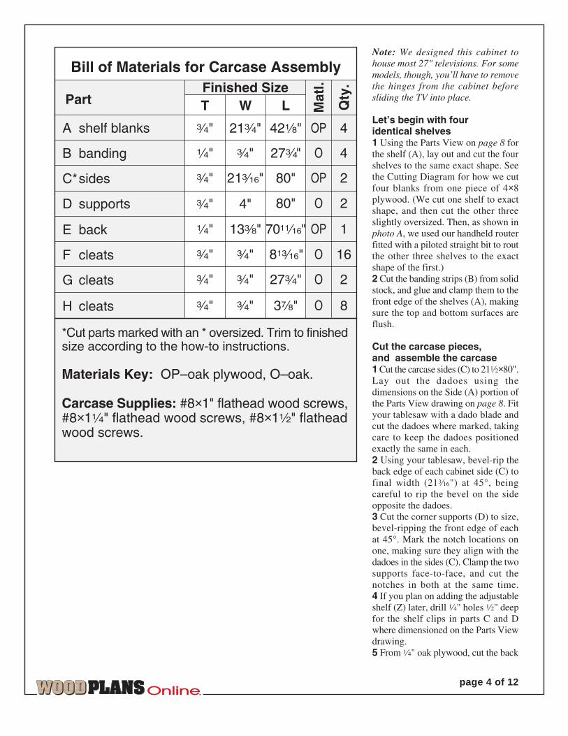
Note: We designed this cabinet tohouse most 27" televisions. For somemodels, though, you’ll have to removethe hinges from the cabinet beforesliding the TV into place.
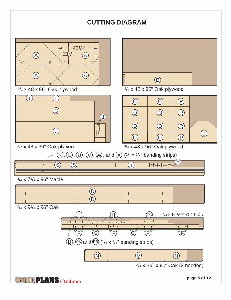
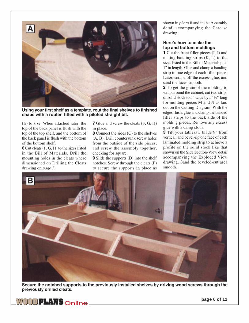
Let’s begin with fouridentical shelves1 Using the Parts View on page 8 forthe shelf (A), lay out and cut the fourshelves to the same exact shape. Seethe Cutting Diagram for how we cutfour blanks from one piece of 4×8plywood. (We cut one shelf to exactshape, and then cut the other threeslightly oversized. Then, as shown inphoto A, we used our handheld routerfitted with a piloted straight bit to routthe other three shelves to the exactshape of the first.)2 Cut the banding strips (B) from solidstock, and glue and clamp them to thefront edge of the shelves (A), makingsure the top and bottom surfaces areflush.
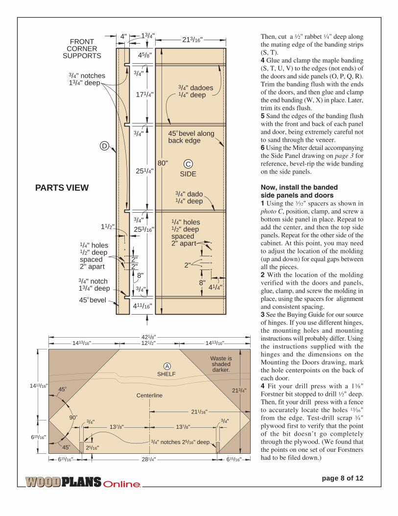
Cut the carcase pieces,and assemble the carcase1 Cut the carcase sides (C) to 21fi×80".Lay out the dadoes using thedimensions on the Side (A) portion ofthe Parts View drawing on page 8. Fityour tablesaw with a dado blade andcut the dadoes where marked, takingcare to keep the dadoes positionedexactly the same in each.2 Using your tablesaw, bevel-rip theback edge of each cabinet side (C) tofinal width (21‰") at 45°, beingcareful to rip the bevel on the sideopposite the dadoes.3 Cut the corner supports (D) to size,bevel-ripping the front edge of eachat 45°. Mark the notch locations onone, making sure they align with thedadoes in the sides (C). Clamp the twosupports face-to-face, and cut thenotches in both at the same time.4 If you plan on adding the adjustableshelf (Z) later, drill ‹" holes fi" deepfor the shelf clips in parts C and Dwhere dimensioned on the Parts Viewdrawing.5 From ‹" oak plywood, cut the back
TM
page 4 of 12
‡"
27‡"‡"‡"G cleats 2O
4"‡"
13›"‹"E back 1OP70Ø"
Part
O 4B banding 27‡"
Bill of Materials for Carcase Assembly
D supports
OP 280"‡" 21‰"
O 280"
Qty
.
A shelf blanks 42¤"‡" 21‡" OP 4
T W LFinished Size
Mat
l.
‹" ‡"
C*sides
F cleats 16O
*Cut parts marked with an * oversized. Trim to finishedsize according to the how-to instructions.
Materials Key: OP–oak plywood, O–oak.
Carcase Supplies: #8×1" flathead wood screws,#8×1‹" flathead wood screws, #8×1fi" flatheadwood screws.
‡" 8Å"
3Œ"‡"‡"H cleats 8O
TM
page 5 of 12
3/4 x 48 x 96" Oak plywood
3/4 x 48 x 96" Oak plywood
1/4 x 48 x 96" Oak plywood
3/4 x 48 x 96" Oak plywood
(1/4 x 3/4" banding strips)
3/4 x 71/4 x 96" Maple
421/8"213/4"
, , , , , and
3/4 x 91/4 x 96" Oak
CUTTING DIAGRAM
3/4 x 51/2 x 72" Oak
(1/4 x 3/4" banding strips), ,and
3/4 x 51/2 x 60" Oak (2 needed)
T
K L
S S
J
ZO O P
OO P
Q Q R
Q Q R
Y
C
A
A
A
A
C
I I
D
D
H H
AAB
CC
M NN
E
VU W X
F G F G F F
BB
TM
page 6 of 12
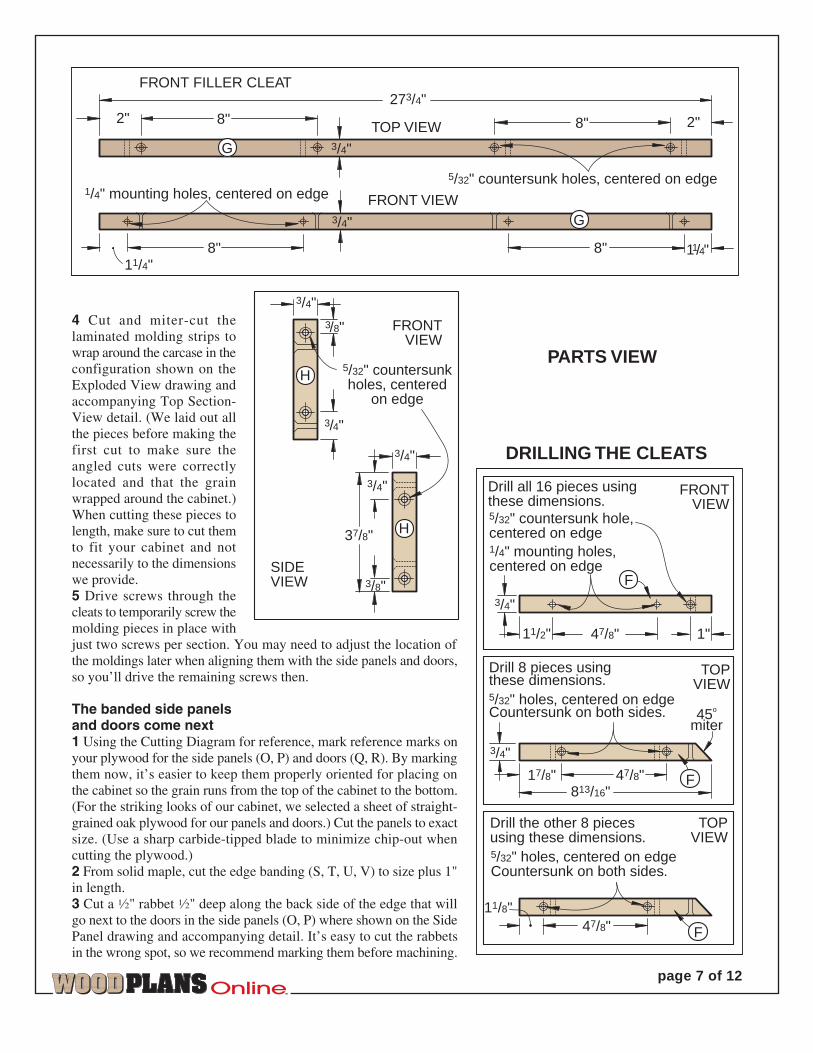
(E) to size. When attached later, thetop of the back panel is flush with thetop of the top shelf, and the bottom ofthe back panel is flush with the bottomof the bottom shelf.6 Cut cleats (F, G, H) to the sizes listedin the Bill of Materials. Drill themounting holes in the cleats wheredimensioned on Drilling the Cleatsdrawing on page 7.
7 Glue and screw the cleats (F, G, H)in place.8 Connect the sides (C) to the shelves(A, B). Drill countersunk screw holesfrom the outside of the side pieces,and screw the assembly together,checking for square.9 Slide the supports (D) into the shelfnotches. Screw through the cleats (F)to secure the supports in place as
shown in photo B and in the Assemblydetail accompanying the Carcasedrawing.
Here’s how to make thetop and bottom moldings1 Cut the front filler pieces (I, J) andmating banding strips (K, L) to thesizes listed in the Bill of Materials plus1" in length. Glue and clamp a bandingstrip to one edge of each filler piece.Later, scrape off the excess glue, andsand the faces smooth.2 To get the grain of the molding towrap around the cabinet, cut two stripsof solid stock to 5" wide by 54fi" longfor molding pieces M and N as laidout on the Cutting Diagram. With theedges flush, glue and clamp the bandedfiller strips to the back side of themolding pieces. Remove any excessglue with a damp cloth.3 Tilt your tablesaw blade 9° fromvertical, and bevel-rip one face of eachlaminated molding strip to achieve aprofile on the solid stock like thatshown on the Side Section-View detailaccompanying the Exploded Viewdrawing. Sand the beveled-cut areasmooth.
Using your first shelf as a template, rout the final shelves to finishedshape with a router fitted with a piloted straight bit.
Secure the notched supports to the previously installed shelves by driving wood screws through thepreviously drilled cleats.
A
B
TM
page 7 of 12
TOP VIEW
FRONT VIEW
FRONT FILLER CLEAT
5/32" countersunk holes, centered on edge1/4" mounting holes, centered on edge
2" 2"
11/4"11/4"
3/4"
273/4"
8" 8"
8"8"
G
G
3/4"
FRONTVIEW
5/32" countersunkholes, centered
on edge
SIDEVIEW
3/8"
3/4"
3/4"
37/8"
3/4"
3/8"
3/4"
H
H
PARTS VIEW
3/4"
45o
miter
47/8"17/8"
1/4" mounting holes,centered on edge
11/8"
Drill the other 8 piecesusing these dimensions.5/32" holes, centered on edgeCountersunk on both sides.
47/8"
813/16"
3/4"
FRONTVIEW
47/8"11/2" 1"
F
Drill 8 pieces usingthese dimensions.5/32" holes, centered on edgeCountersunk on both sides.
Drill all 16 pieces usingthese dimensions.5/32" countersunk hole,centered on edge
F
TOPVIEW
TOPVIEW
DRILLING THE CLEATS
F
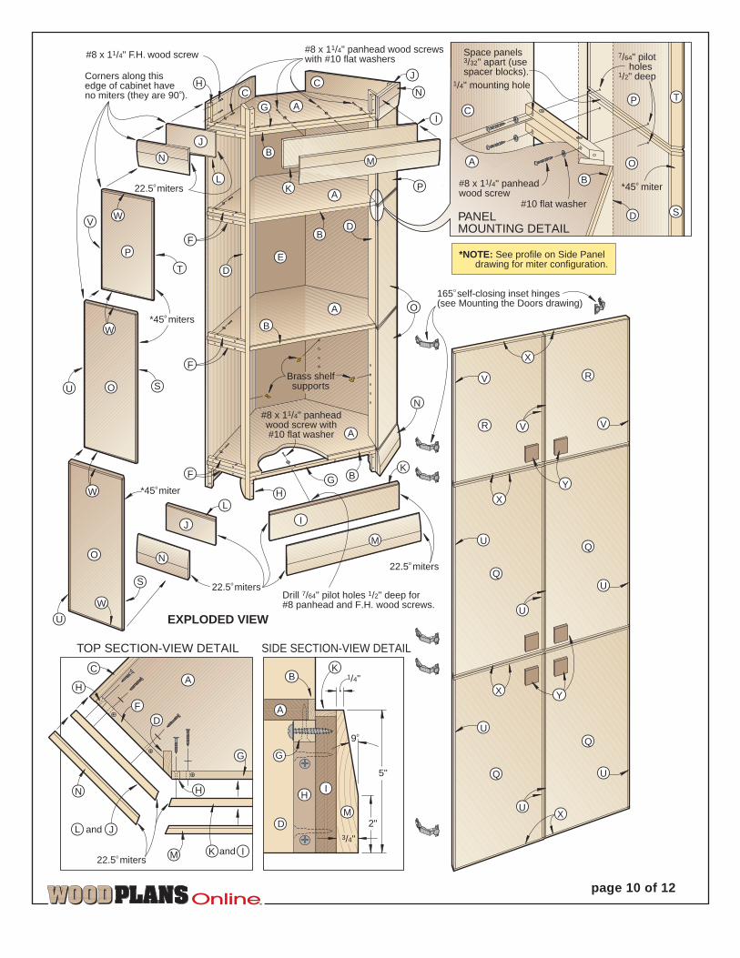
4 Cut and miter-cut thelaminated molding strips towrap around the carcase in theconfiguration shown on theExploded View drawing andaccompanying Top Section-View detail. (We laid out allthe pieces before making thefirst cut to make sure theangled cuts were correctlylocated and that the grainwrapped around the cabinet.)When cutting these pieces tolength, make sure to cut themto fit your cabinet and notnecessarily to the dimensionswe provide.5 Drive screws through thecleats to temporarily screw themolding pieces in place withjust two screws per section. You may need to adjust the location ofthe moldings later when aligning them with the side panels and doors,so you’ll drive the remaining screws then.
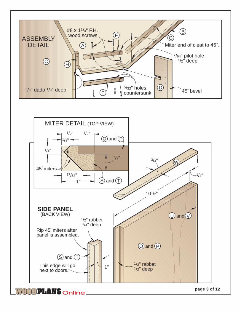
The banded side panelsand doors come next1 Using the Cutting Diagram for reference, mark reference marks onyour plywood for the side panels (O, P) and doors (Q, R). By markingthem now, it’s easier to keep them properly oriented for placing onthe cabinet so the grain runs from the top of the cabinet to the bottom.(For the striking looks of our cabinet, we selected a sheet of straight-grained oak plywood for our panels and doors.) Cut the panels to exactsize. (Use a sharp carbide-tipped blade to minimize chip-out whencutting the plywood.)2 From solid maple, cut the edge banding (S, T, U, V) to size plus 1"in length.3 Cut a fi" rabbet fi" deep along the back side of the edge that willgo next to the doors in the side panels (O, P) where shown on the SidePanel drawing and accompanying detail. It’s easy to cut the rabbetsin the wrong spot, so we recommend marking them before machining.
TM
page 8 of 12
45o
45o
1413/16" 121/2"
615/16"
3/4"
Centerline213/4"
3/4" notches 25/16" deep
Waste isshadeddarker.
SHELF
421/8"
3/4"90o
1413/16"
281/4"
137/8" 137/8"
211/16"
615/16"
615/16"
1413/16"
25/16"
A
3/4" dadoes1/4" deep
45o bevel alongback edge
45o bevel
3/4" notches13/4" deep
4" 213/16"
3/4"
45/8"
411/16"
80"
FRONTCORNER
SUPPORTS
SIDE
8"
2"
1/4" holes1/2" deepspaced2" apart
8"
2"
41/4"
1/4" holes1/2" deepspaced2" apart
3/4" dado1/4" deep
171/4"
251/4"
253/16"
3/4"3/4" notch13/4" deep
11/2"
2"
C
3/4"
3/4"
D
Then, cut a fi" rabbet ‹" deep alongthe mating edge of the banding strips(S, T).4 Glue and clamp the maple banding(S, T, U, V) to the edges (not ends) ofthe doors and side panels (O, P, Q, R).Trim the banding flush with the endsof the doors, and then glue and clampthe end banding (W, X) in place. Later,trim its ends flush.5 Sand the edges of the banding flushwith the front and back of each paneland door, being extremely careful notto sand through the veneer.6 Using the Miter detail accompanyingthe Side Panel drawing on page 3 forreference, bevel-rip the wide bandingon the side panels.
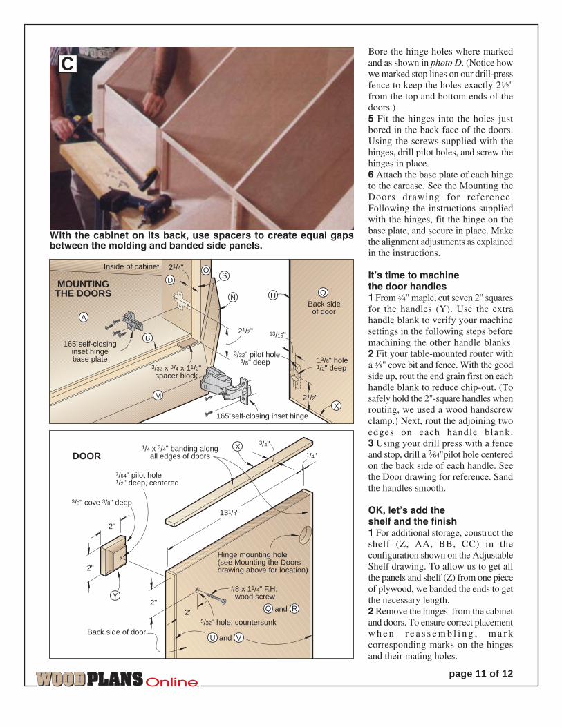
Now, install the bandedside panels and doors1 Using the Ï" spacers as shown inphoto C, position, clamp, and screw abottom side panel in place. Repeat toadd the center, and then the top sidepanels. Repeat for the other side of thecabinet. At this point, you may needto adjust the location of the molding(up and down) for equal gaps betweenall the pieces.2 With the location of the moldingverified with the doors and panels,glue, clamp, and screw the molding inplace, using the spacers for alignmentand consistent spacing.3 See the Buying Guide for our sourceof hinges. If you use different hinges,the mounting holes and mountinginstructions will probably differ. Usingthe instructions supplied with thehinges and the dimensions on theMounting the Doors drawing, markthe hole centerpoints on the back ofeach door.4 Fit your drill press with a 1›"Forstner bit stopped to drill fi" deep.Then, fit your drill press with a fenceto accurately locate the holes Å"from the edge. Test-drill scrap ‡"plywood first to verify that the pointof the bit doesn’t go completelythrough the plywood. (We found thatthe points on one set of our Forstnershad to be filed down.)
PARTS VIEW
13/4"
‡"
12
M
M
6
‹"
‹" ‡"
‡"
17›"
13‡"
OP 217›"10fi"
TM
page 9 of 12
N*molding
V* banding
Qty
.
Bill of Materials
‡" OP 2
Part T W LFinished Size
Mat
l.
‡" 4‡"
2
J* filler strips
K* banding
10Œ"L* banding
‡" OM* molding
‡" 5"
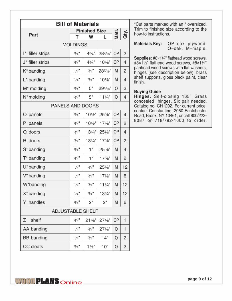
*Cut parts marked with an * oversized.Trim to finished size according to thehow-to instructions.
Materials Key: OP–oak plywood, O–oak, M–maple.
Supplies: #8×1‹" flathead wood screws,#8×1fi" flathead wood screws, #8×1‹"panhead wood screws with flat washers,hinges (see description below), brassshelf supports, gloss black paint, clearfinish.
Buying GuideHinges. Self-closing 165° Grassconcealed hinges. Six pair needed.Catalog no. CH1202. For current price,contact Constantine, 2050 EastchesterRoad, Bronx, NY 10461, or call 800/223-8087 or 718/792-1600 to order.
‡"P panels
‡"Q doors
‡"R doors
‡"S* banding
‡"T* banding
U*banding
X* banding
‡" 6Y handles
I* filler strips
‹"
‹"
‹"
MOLDINGS
PANELS AND DOORS
4‡"
‡"
‡"
5"
13‹"
13‹"
1"
1"
‡"
2"
28Á"
10Œ"
28Á"
29„"
11‹"
25›"
17›"
25›"
17›"
25›"
2"
OP
M
M
O
OP
OP
M
M
M
M
4
4
4
2
4
2
4
2
12
OP 425›"10fi"‡"O panels
M 12‹" ‡" 11‹"W*banding
‡" 121›" 27¤" OP
‹" 1AA banding ‡" 27fl" O
‹" 2BB banding ‡" 14" O
2CC cleats 1fi" 10" O
ADJUSTABLE SHELF
Z shelf
TM
page 10 of 12
J
A
A
A
A
E
Corners along thisedge of cabinet haveno miters (they are 90o).
22.5o miters
#8 x 11/4" panhead wood screwswith #10 flat washers
*45o miters
22.5o miters
*45o miter
#8 x 11/4" panheadwood screw with#10 flat washer
165O self-closing inset hinges(see Mounting the Doors drawing)
I
PANELMOUNTING DETAIL
C
*45o miter
7/64" pilot holes1/2" deep
1/4" mounting hole
Space panels3/32" apart (usespacer blocks).
#8 x 11/4" panheadwood screw
#10 flat washer
A
22.5o miters
SIDE SECTION-VIEW DETAILTOP SECTION-VIEW DETAIL
22.5o miters
A
F A
1/4"
5"
2"3/4"
EXPLODED VIEW
S
O
N M
IG
F
D
C
B
B
B
B
D
F
FG
J
K
H
L
D
B
S
B
GG
D
M
#8 x 11/4" F.H. wood screw
N
O
V
U
R
W
X
Y
Q
P
P
T
U
S
W
W
W
N
J
L
M
K
P T
O
V
VV
X
X
X
Y
U
R
Q
Q
Q
N
U
U
U
U
U
H
9o
K
IH
M
N
JandL
H
C
H
Drill 7/64" pilot holes 1/2" deep for#8 panhead and F.H. wood screws.
Brass shelfsupports
C
O
IandK
D
*NOTE: See profile on Side Panel drawing for miter configuration.
and2"2"
2"
2"
3/8" cove 3/8" deep
7/64" pilot hole1/2" deep, centered
1/4 x 3/4" banding alongall edges of doors
131/4"
Hinge mounting hole(see Mounting the Doorsdrawing above for location)
#8 x 11/4" F.H. wood screw
5/32" hole, countersunkBack side of door
DOOR 1/4"
3/4"
and
13/16"
21/2"
13/8" hole1/2" deep
Back side of door
3/32" pilot hole 3/8" deep
165o self-closinginset hingebase plate
3/32 x 3/4 x 11/2"spacer block
Inside of cabinet
MOUNTINGTHE DOORS
21/2"
21/4"
165o self-closing inset hinge
U
XM
D
B
A
O
X
VU
R
Y
Q
Q
S
N
Bore the hinge holes where markedand as shown in photo D. (Notice howwe marked stop lines on our drill-pressfence to keep the holes exactly 2fi"from the top and bottom ends of thedoors.)5 Fit the hinges into the holes justbored in the back face of the doors.Using the screws supplied with thehinges, drill pilot holes, and screw thehinges in place.6 Attach the base plate of each hingeto the carcase. See the Mounting theDoors drawing for reference.Following the instructions suppliedwith the hinges, fit the hinge on thebase plate, and secure in place. Makethe alignment adjustments as explainedin the instructions.
It’s time to machinethe door handles1 From ‡" maple, cut seven 2" squaresfor the handles (Y). Use the extrahandle blank to verify your machinesettings in the following steps beforemachining the other handle blanks.2 Fit your table-mounted router witha ›" cove bit and fence. With the goodside up, rout the end grain first on eachhandle blank to reduce chip-out. (Tosafely hold the 2"-square handles whenrouting, we used a wood handscrewclamp.) Next, rout the adjoining twoedges on each handle blank.3 Using your drill press with a fenceand stop, drill a 7⁄64"pilot hole centeredon the back side of each handle. Seethe Door drawing for reference. Sandthe handles smooth.
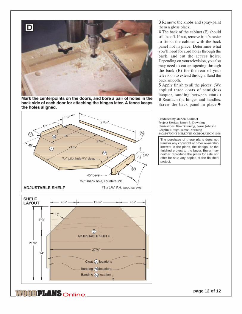
OK, let’s add theshelf and the finish1 For additional storage, construct theshelf (Z, AA, BB, CC) in theconfiguration shown on the AdjustableShelf drawing. To allow us to get allthe panels and shelf (Z) from one pieceof plywood, we banded the ends to getthe necessary length.2 Remove the hinges from the cabinetand doors. To ensure correct placementw h e n r e a s s e m b l i n g , m a r kcorresponding marks on the hingesand their mating holes.
TM
page 11 of 12
With the cabinet on its back, use spacers to create equal gapsbetween the molding and banded side panels.
C
3 Remove the knobs and spray-paintthem a gloss black.4 The back of the cabinet (E) shouldstill be off. If not, remove it; it’s easierto finish the cabinet with the backpanel not in place. Determine whatyou’ll need for cord holes through theback, and cut the access holes.Depending on your television, you alsomay need to cut an opening throughthe back (E) for the rear of yourtelevision to extend through. Sand theback smooth.5 Apply finish to all the pieces. (Weapplied three coats of semiglosslacquer, sanding between coats.)6 Reattach the hinges and handles.Screw the back panel in place.¿
TM
page 12 of 12
Cleat locations
Banding location
Banding locations
ADJUSTABLE SHELF
45o
14"
73/8"
Z
BB
AA
14"
33/4"
10"
45o bevel
#8 x 11/2" F.H. wood screws
5/32" shank hole, countersunk
7/64" pilot hole 3/4" deep
ADJUSTABLE SHELF
45O
271/8"
Z
BBCC
BB
CC
275/8"
11/2"
AA
213/8"
123/8"73/8"
73/8"
213/8"
271/8"
CC
SHELFLAYOUT
D
Mark the centerpoints on the doors, and bore a pair of holes in theback side of each door for attaching the hinges later. A fence keepsthe holes aligned.
Produced by Marlen KemmetProject Design: James R. Downing·Illustrations: Kim Downing, Lorna JohnsonGraphic Design: Jamie Downing©COPYRIGHT MEREDITH CORPORATION 1998
The purchase of these plans does nottransfer any copyright or other ownershipinterest in the plans, the design, or thefinished project to the buyer. Buyer mayneither reproduce the plans for sale noroffer for sale any copies of the finishedproject.