wireless communications introduction and wireless transmission
TRANSCRIPT
Wireless Communications
Introduction and Wireless Transmission
Mobile communication
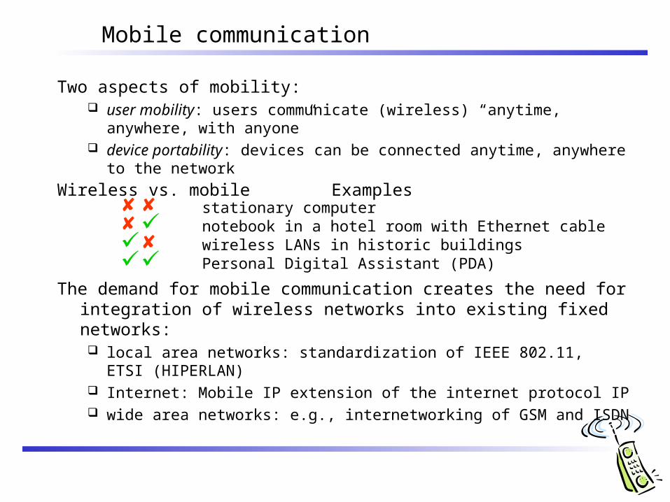
Two aspects of mobility: user mobility: users communicate (wireless) “anytime, anywhere, with
anyone” device portability: devices can be connected anytime, anywhere to the
network
Wireless vs. mobile Examples stationary computer notebook in a hotel room with Ethernet cable wireless LANs in historic buildings Personal Digital Assistant (PDA)
The demand for mobile communication creates the need for integration of wireless networks into existing fixed networks: local area networks: standardization of IEEE 802.11,
ETSI (HIPERLAN) Internet: Mobile IP extension of the internet protocol IP wide area networks: e.g., internetworking of GSM and ISDN
Effects of device portability
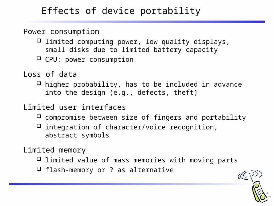
Power consumption limited computing power, low quality displays, small disks due to
limited battery capacity CPU: power consumption
Loss of data higher probability, has to be included in advance into the design
(e.g., defects, theft)
Limited user interfaces compromise between size of fingers and portability integration of character/voice recognition, abstract symbols
Limited memory limited value of mass memories with moving parts flash-memory or ? as alternative
Wireless networks in comparison to fixed networks
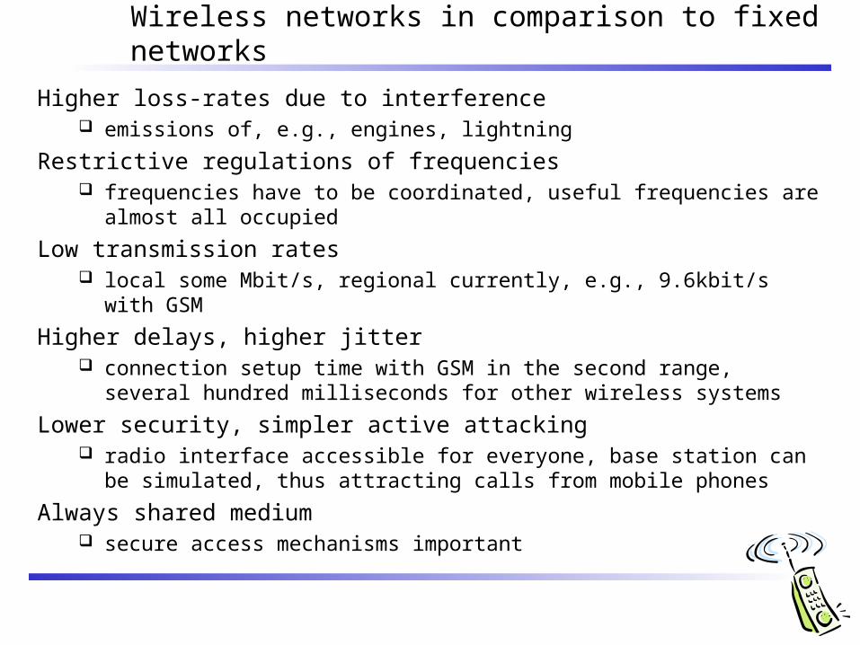
Higher loss-rates due to interference emissions of, e.g., engines, lightning
Restrictive regulations of frequencies frequencies have to be coordinated, useful frequencies are almost all
occupied
Low transmission rates local some Mbit/s, regional currently, e.g., 9.6kbit/s with GSM
Higher delays, higher jitter connection setup time with GSM in the second range, several hundred
milliseconds for other wireless systems
Lower security, simpler active attacking radio interface accessible for everyone, base station can be simulated, thus
attracting calls from mobile phones
Always shared medium secure access mechanisms important
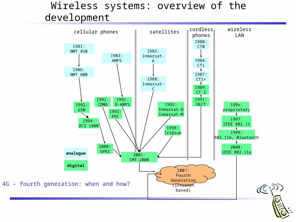
Wireless systems: overview of the development
cellular phones satellites wireless LANcordlessphones
1992:GSM
1994:DCS 1800
2001:IMT-2000
1987:CT1+
1982:Inmarsat-A
1992:Inmarsat-BInmarsat-M
1998:Iridium
1989:CT 2
1991:DECT 199x:
proprietary
1997:IEEE 802.11
1999:802.11b, Bluetooth
1988:Inmarsat-C
analogue
digital
1991:D-AMPS
1991:CDMA
1981:NMT 450
1986:NMT 900
1980:CT0
1984:CT1
1983:AMPS
1993:PDC
4G – fourth generation: when and how?
2000:GPRS
2000:IEEE 802.11a
200?:Fourth Generation(Internet based)
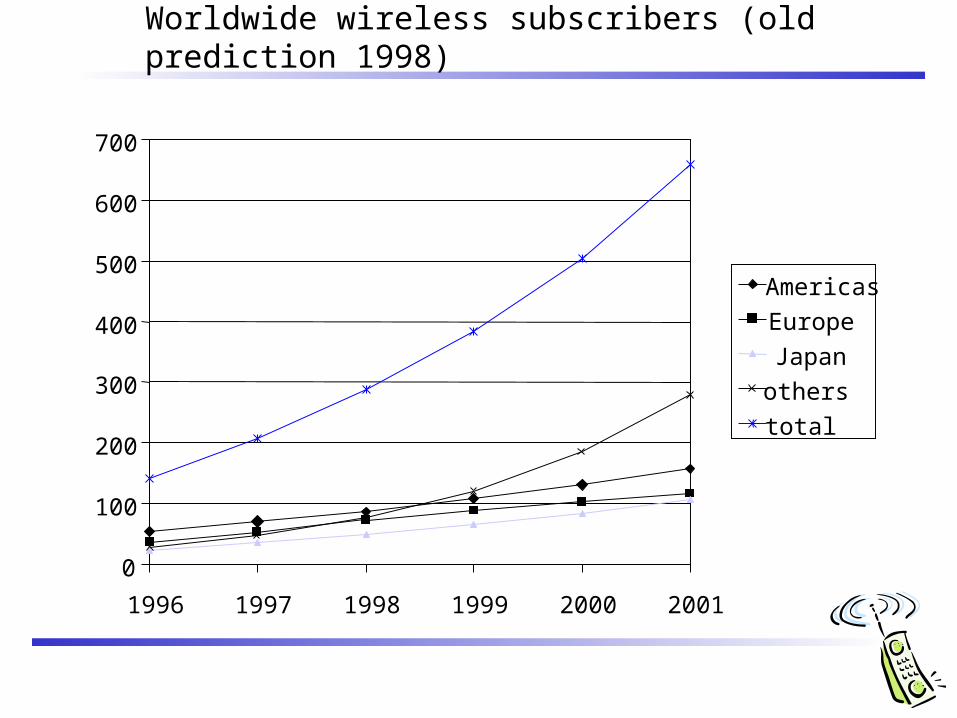
Worldwide wireless subscribers (old prediction 1998)
0
100
200
300
400
500
600
700
1996 1997 1998 1999 2000 2001
Americas
Europe
Japan
others
total
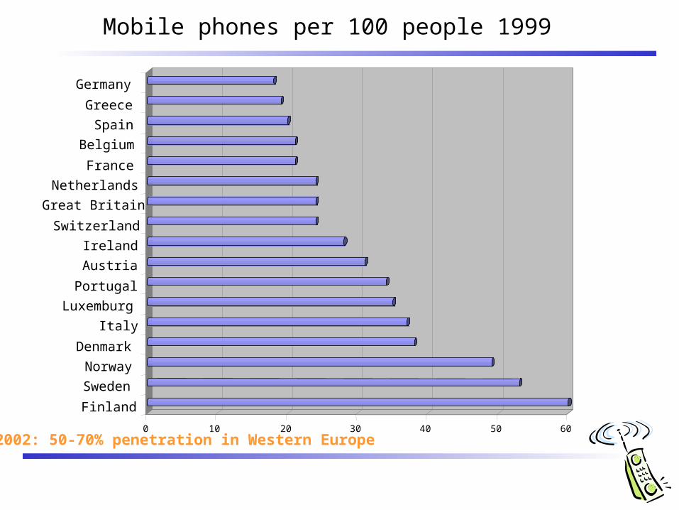
Mobile phones per 100 people 1999
0 10 20 30 40 50 60
Finland
Sweden
Norway
Denmark
Italy
Luxemburg
Portugal
Austria
Ireland
Switzerland
Great Britain
Netherlands
France
Belgium
Spain
Greece
Germany
2002: 50-70% penetration in Western Europe
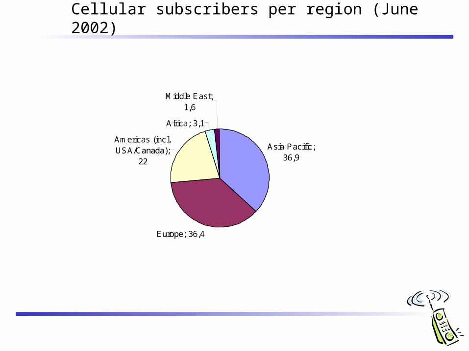
Cellular subscribers per region (June 2002)
Asia Pacific; 36,9
Europe; 36,4
Americas (incl. USA/Canada);
22
Africa; 3,1
Middle East; 1,6
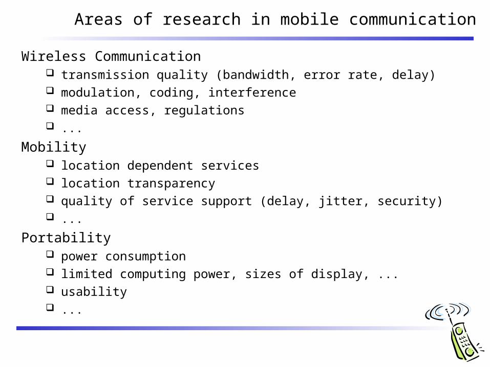
Areas of research in mobile communication
Wireless Communication transmission quality (bandwidth, error rate, delay) modulation, coding, interference media access, regulations ...
Mobility location dependent services location transparency quality of service support (delay, jitter, security) ...
Portability power consumption limited computing power, sizes of display, ... usability ...
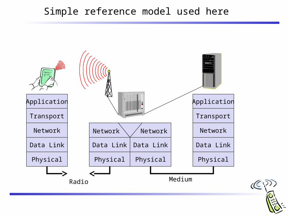
Simple reference model used here
Application
Transport
Network
Data Link
Physical
Medium
Data Link
Physical
Application
Transport
Network
Data Link
Physical
Data Link
Physical
Network Network
Radio
Wireless Transmission
Frequencies SignalsSignal propagationMultiplexing
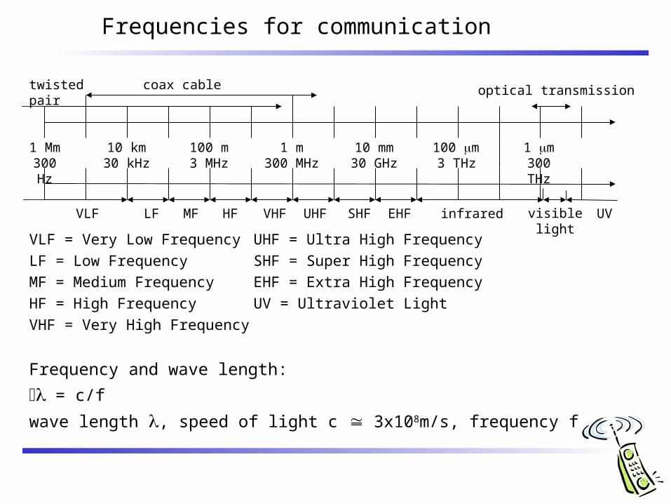
Frequencies for communication
VLF = Very Low Frequency UHF = Ultra High Frequency
LF = Low Frequency SHF = Super High Frequency
MF = Medium Frequency EHF = Extra High Frequency
HF = High Frequency UV = Ultraviolet Light
VHF = Very High Frequency
Frequency and wave length:
= c/f
wave length , speed of light c 3x10⁸m/s, frequency f
1 Mm300 Hz
10 km30 kHz
100 m3 MHz
1 m300 MHz
10 mm30 GHz
100 m3 THz
1 m300 THz
visible lightVLF LF MF HF VHF UHF SHF EHF infrared UV
optical transmissioncoax cabletwisted pair
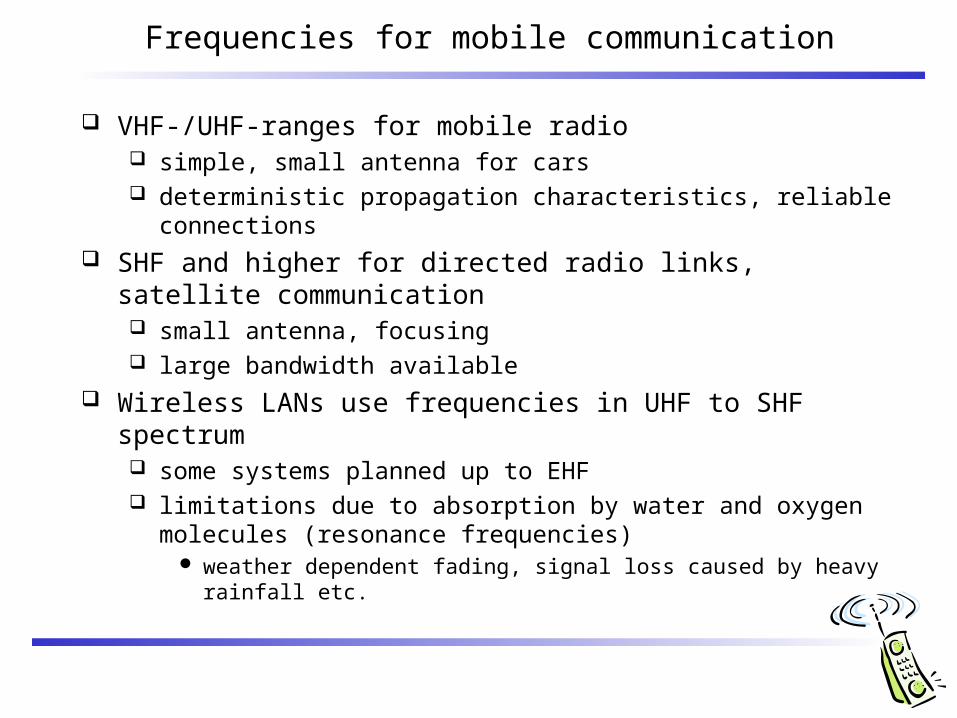
Frequencies for mobile communication
VHF-/UHF-ranges for mobile radio simple, small antenna for cars deterministic propagation characteristics, reliable connections
SHF and higher for directed radio links, satellite communication small antenna, focusing large bandwidth available
Wireless LANs use frequencies in UHF to SHF spectrum some systems planned up to EHF limitations due to absorption by water and oxygen molecules
(resonance frequencies) weather dependent fading, signal loss caused by heavy rainfall etc.
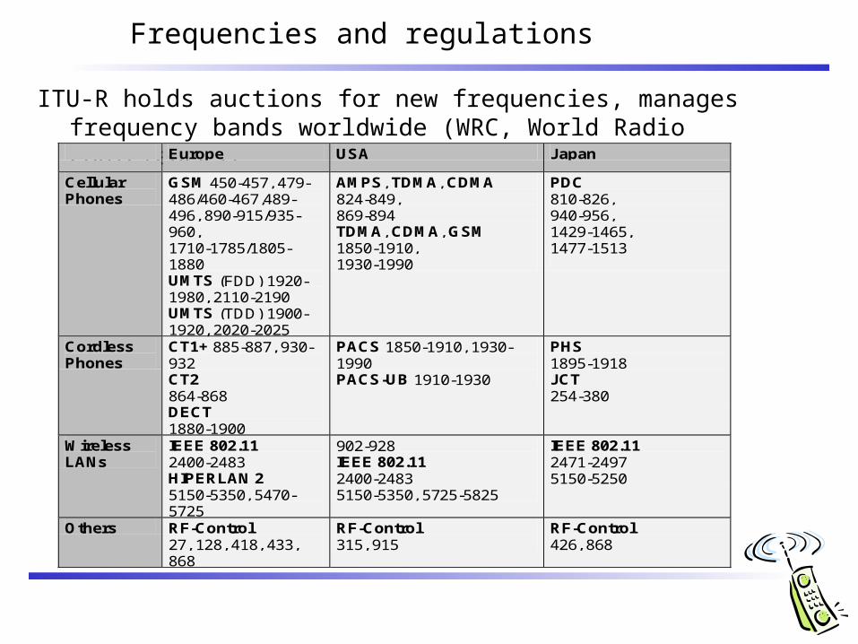
Frequencies and regulations
ITU-R holds auctions for new frequencies, manages frequency bands worldwide (WRC, World Radio Conferences)
Europe USA Japan
Cellular Phones
GSM 450-457, 479-486/460-467,489-496, 890-915/935-960, 1710-1785/1805-1880 UMTS (FDD) 1920-1980, 2110-2190 UMTS (TDD) 1900-1920, 2020-2025
AMPS, TDMA, CDMA 824-849, 869-894 TDMA, CDMA, GSM 1850-1910, 1930-1990
PDC 810-826, 940-956, 1429-1465, 1477-1513
Cordless Phones
CT1+ 885-887, 930-932 CT2 864-868 DECT 1880-1900
PACS 1850-1910, 1930-1990 PACS-UB 1910-1930
PHS 1895-1918 JCT 254-380
Wireless LANs
IEEE 802.11 2400-2483 HIPERLAN 2 5150-5350, 5470-5725
902-928 IEEE 802.11 2400-2483 5150-5350, 5725-5825
IEEE 802.11 2471-2497 5150-5250
Others RF-Control 27, 128, 418, 433, 868
RF-Control 315, 915
RF-Control 426, 868
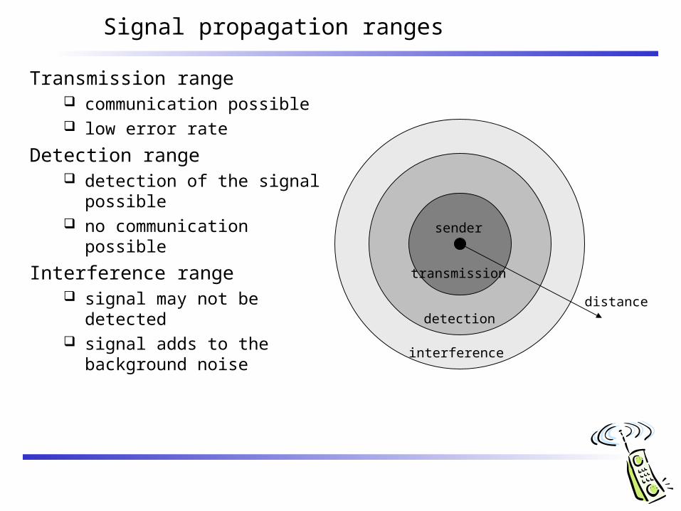
Signal propagation ranges
distance
sender
transmission
detection
interference
Transmission range communication possible low error rate
Detection range detection of the signal
possible no communication
possible
Interference range signal may not be
detected signal adds to the
background noise
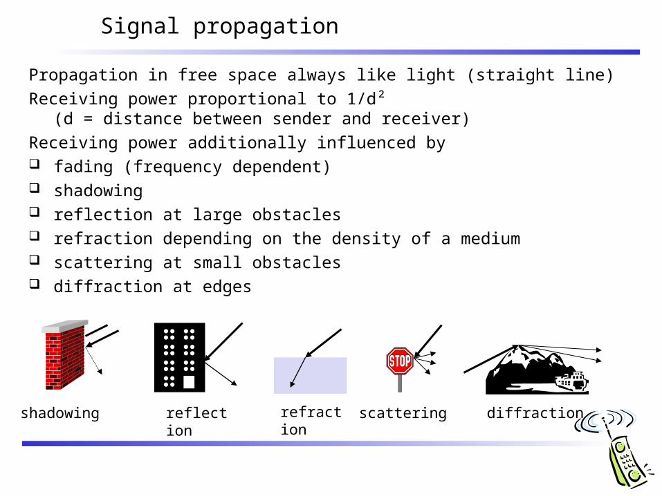
Signal propagation
Propagation in free space always like light (straight line)
Receiving power proportional to 1/d² (d = distance between sender and receiver)
Receiving power additionally influenced by fading (frequency dependent) shadowing reflection at large obstacles refraction depending on the density of a medium scattering at small obstacles diffraction at edges
reflection scattering diffractionshadowing refraction
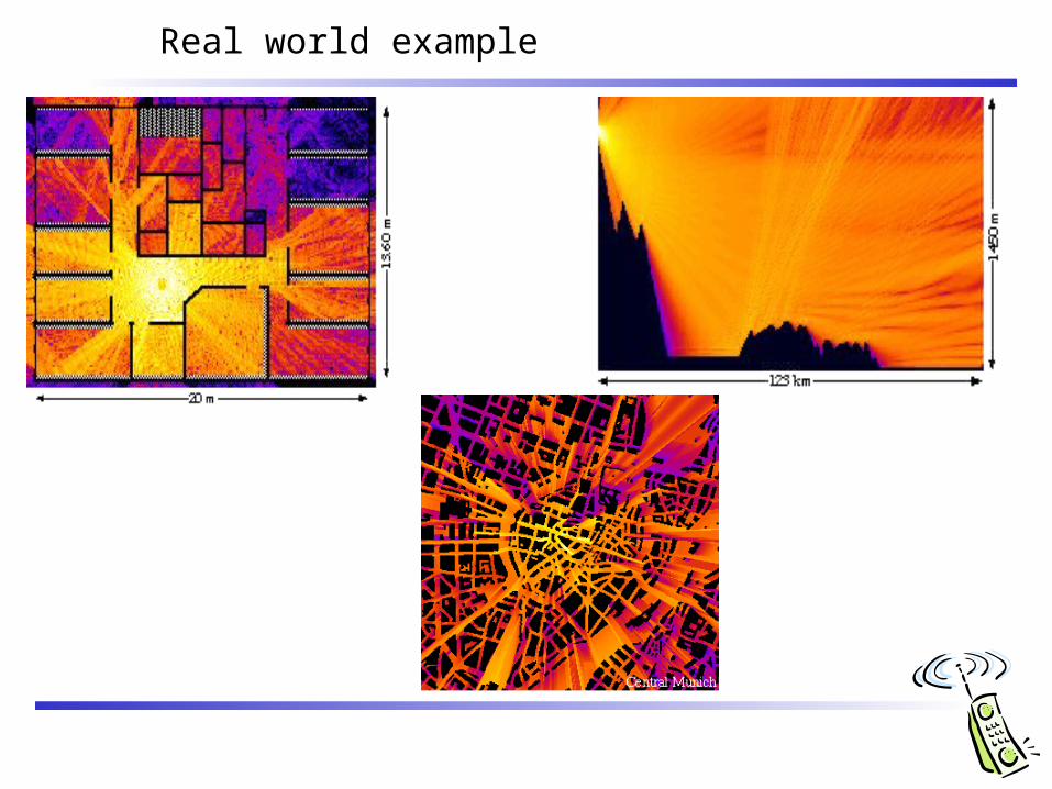
Real world example
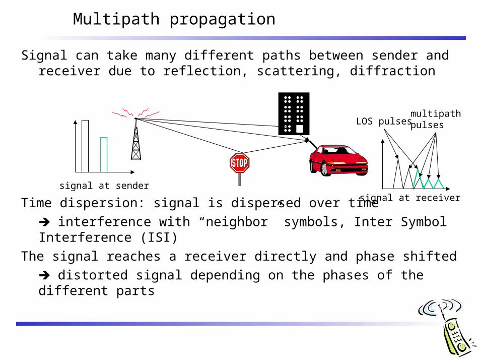
Signal can take many different paths between sender and receiver due to reflection, scattering, diffraction
Time dispersion: signal is dispersed over time
interference with “neighbor” symbols, Inter Symbol Interference (ISI)
The signal reaches a receiver directly and phase shifted
distorted signal depending on the phases of the different parts
Multipath propagation
signal at sendersignal at receiver
LOS pulsesmultipathpulses
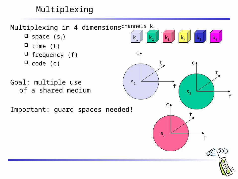
Multiplexing in 4 dimensions space (si)
time (t) frequency (f) code (c)
Goal: multiple use of a shared medium
Important: guard spaces needed!
s2
s3
s1
Multiplexing
f
t
c
k2 k3 k4 k5 k6k1
f
t
c
f
t
c
channels ki
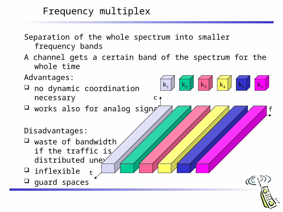
Frequency multiplex
Separation of the whole spectrum into smaller frequency bands
A channel gets a certain band of the spectrum for the whole time
Advantages: no dynamic coordination
necessary works also for analog signals
Disadvantages: waste of bandwidth
if the traffic is distributed unevenly
inflexible guard spaces
k2 k3 k4 k5 k6k1
f
t
c
f
t
c
k2 k3 k4 k5 k6k1
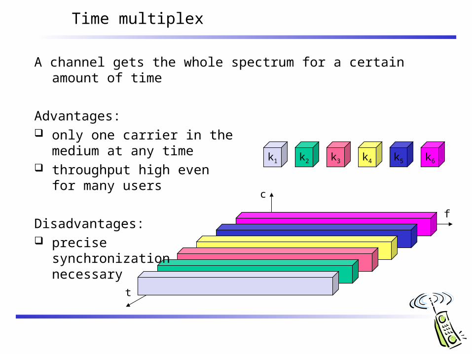
Time multiplex
A channel gets the whole spectrum for a certain amount of time
Advantages: only one carrier in the
medium at any time throughput high even
for many users
Disadvantages: precise
synchronization necessary
f
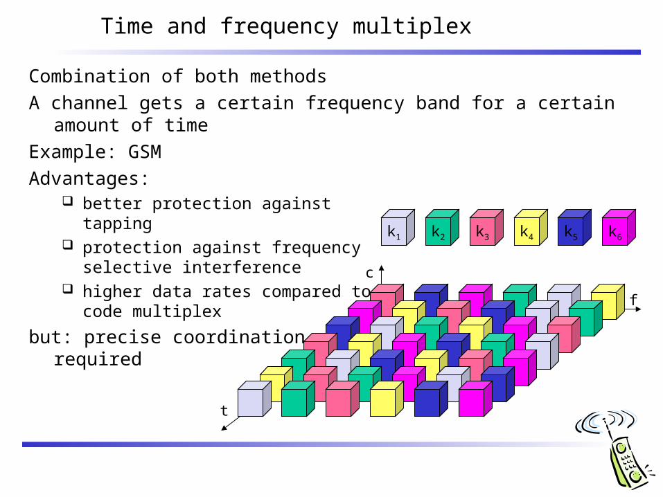
Time and frequency multiplex
Combination of both methods
A channel gets a certain frequency band for a certain amount of time
Example: GSM
Advantages: better protection against
tapping protection against frequency
selective interference higher data rates compared to
code multiplex
but: precise coordinationrequired
t
c
k2 k3 k4 k5 k6k1
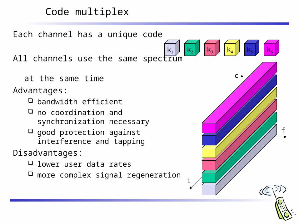
Code multiplex
Each channel has a unique code
All channels use the same spectrum at the same time
Advantages: bandwidth efficient no coordination and synchronization
necessary good protection against interference and
tapping
Disadvantages: lower user data rates more complex signal regeneration
k2 k3 k4 k5 k6k1
f
t
c
Modulation
Basic schemes Amplitude Modulation (AM) Frequency Modulation (FM) Phase Modulation (PM)
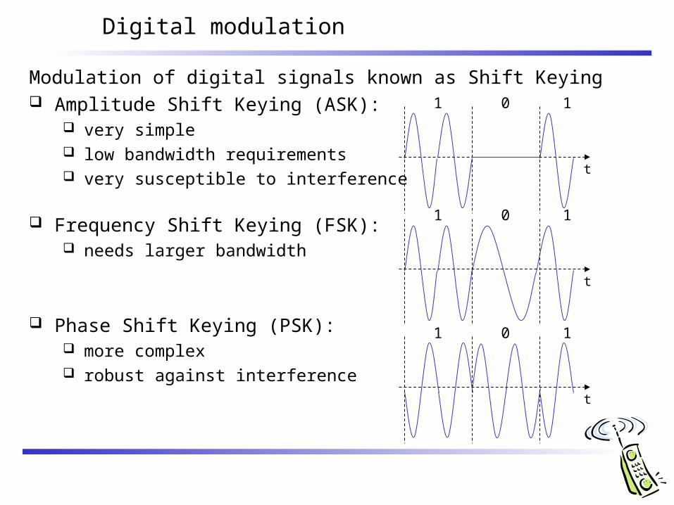
Digital modulation
Modulation of digital signals known as Shift Keying Amplitude Shift Keying (ASK):
very simple low bandwidth requirements very susceptible to interference
Frequency Shift Keying (FSK): needs larger bandwidth
Phase Shift Keying (PSK): more complex robust against interference
1 0 1
t
1 0 1
t
1 0 1
t
Cell structure
Implements space division multiplex: base station covers a certain transmission area (cell)
Mobile stations communicate only via the base station
Advantages of cell structures: higher capacity, higher number of users less transmission power needed more robust, decentralized base station deals with interference, transmission area etc. locally
Problems: fixed network needed for the base stations handover (changing from one cell to another) necessary interference with other cells
Cell sizes from some 100 m in cities to, e.g., 35 km on the country side (GSM) - even less for higher frequencies
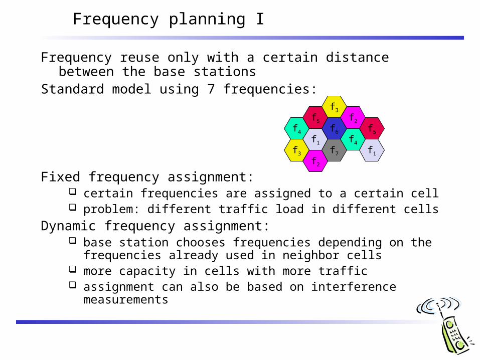
Frequency planning I
Frequency reuse only with a certain distance between the base stations
Standard model using 7 frequencies:
Fixed frequency assignment: certain frequencies are assigned to a certain cell problem: different traffic load in different cells
Dynamic frequency assignment: base station chooses frequencies depending on the frequencies
already used in neighbor cells more capacity in cells with more traffic assignment can also be based on interference measurements
f4
f5
f1
f3
f2
f6
f7
f3
f2
f4
f5
f1
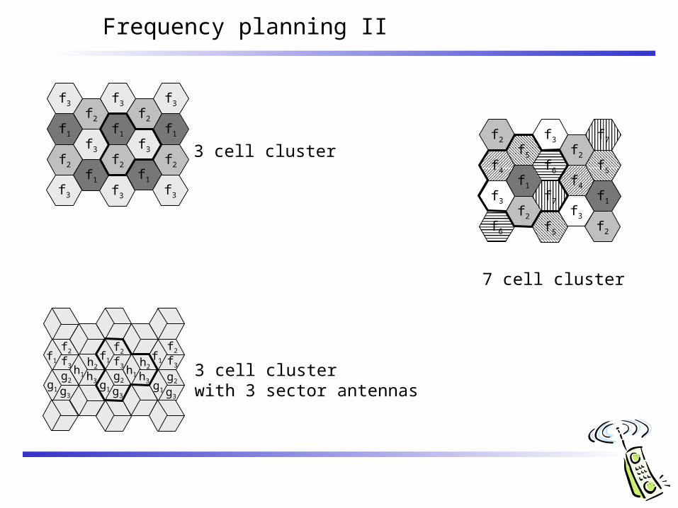
Frequency planning II
f1
f2
f3
f2
f1
f1
f2
f3
f2
f3
f1
f2
f1
f3f3
f3f3
f3
f4
f5
f1
f3
f2
f6
f7
f3
f2
f4
f5
f1
f3
f5f6
f7f2
f2
f1f1 f1
f2
f3
f2
f3
f2
f3h1
h2
h3g1
g2
g3
h1
h2
h3g1
g2
g3g1
g2
g3
3 cell cluster
7 cell cluster
3 cell clusterwith 3 sector antennas