wireless color forecast station color forecast station temperature trend indicator humidity trend...
TRANSCRIPT
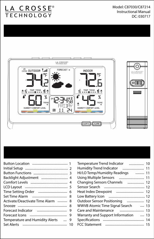
Model: C87030/C87214Instructional Manual
DC: 030717
Table Of Contents
Wireless Color Forecast Station
Temperature Trend IndicatorHumidity Trend IndicatorHI/LO Temp/Humidity ReadingsUsing Multiple SensorsChanging Sensors ChannelsSensor SearchHeat Index DewpointLow Battery IconOutdoor Sensor PositioningWWVB Atomic Time Signal SearchCare and MaintenanceWarranty and Support InformationSpecificationsFCC Statement
Button Location Initial SetupButton FunctionsBacklight AdjustmentComfort LevelsLCD LayoutTime Setting OrderSet Time AlarmActivate/Deactivate Time AlarmSnoozeForecast IndicatorForecast IconsTemperature and Humidity AlertsSet Alerts
1.............................................
............................................
................................... 3............................. 4
....................................... 4..................................................... 5
.................................... 6........................................... 8
............ 8............................................................. 8
..................................... 9.............................................. 9
11...................................
................ 12
.................................. 12
..................... 12..... 13
.............................. 13..... 13
................................................... 14
..................................
.... 9....................................................... 10 ................................................ 15
.................................................. 12
11
12
.................... 1110..............
2
Back View
51 2
Front View1
Alarm
Front Buttons
2
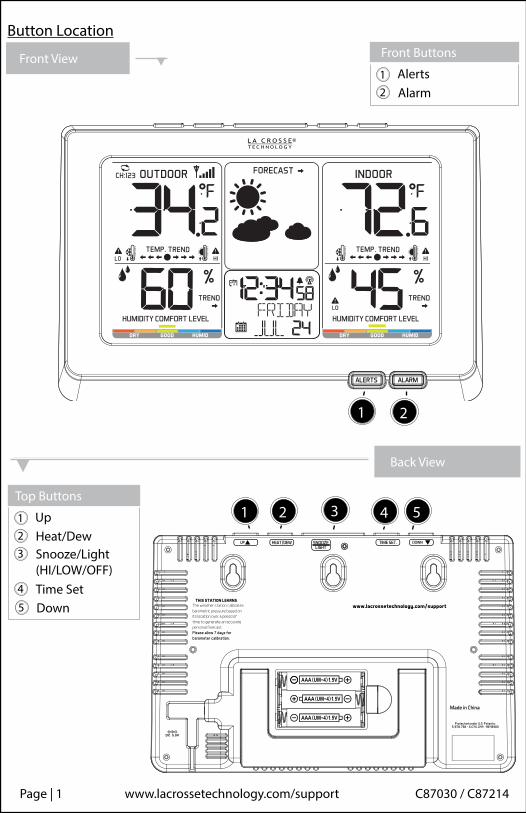
Alerts
Button Location
3 41
Heat/Dew
Top Buttons
2
Up
Snooze/Light(HI/LOW/OFF)
3
Time Set4
Down5
1 2
Page | 1 www.lacrossetechnology.com/support C87030 / C87214
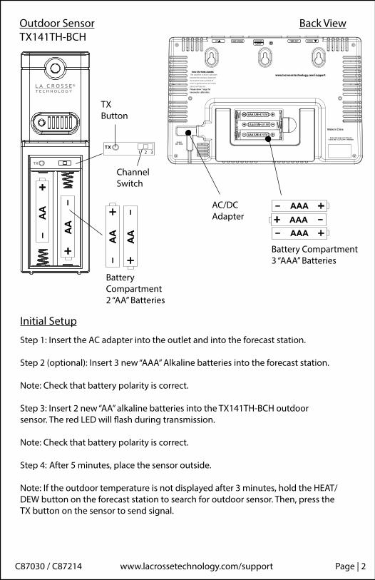
Initial Setup
Outdoor SensorTX141TH-BCH
Battery Compartment3 “AAA” Batteries
Back View
AAAAAA
C87030 / C87214 www.lacrossetechnology.com/support Page | 2
AAA
Step 1: Insert the AC adapter into the outlet and into the forecast station.
Step 2 (optional): Insert 3 new “AAA” Alkaline batteries into the forecast station.
Note: Check that battery polarity is correct.
Step 3: Insert 2 new “AA” alkaline batteries into the TX141TH-BCH outdoor sensor. The red LED will flash during transmission.
Note: Check that battery polarity is correct.
Step 4: After 5 minutes, place the sensor outside.
Note: If the outdoor temperature is not displayed after 3 minutes, hold the HEAT/DEW button on the forecast station to search for outdoor sensor. Then, press the TX button on the sensor to send signal.
1 2 3
AA
AA
AA
AA
AC/DC Adapter
TXButton
Channel Switch
Battery Compartment2 “AA” Batteries
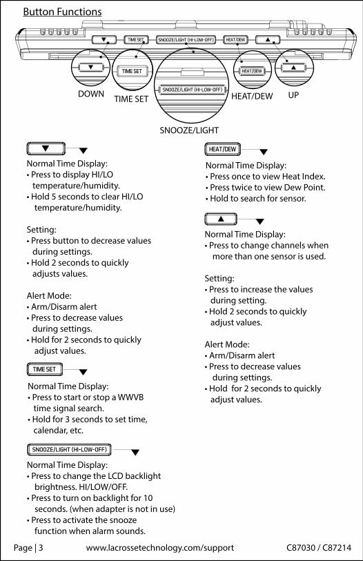
Button Functions
TIME SET HEAT/DEW UPDOWN
Normal Time Display:• Press to start or stop a WWVB time signal search.• Hold for 3 seconds to set time, calendar, etc.
Normal Time Display:• Press to change the LCD backlight brightness. HI/LOW/OFF.• Press to turn on backlight for 10 seconds. (when adapter is not in use)• Press to activate the snooze function when alarm sounds.
Normal Time Display:• Press once to view Heat Index.• Press twice to view Dew Point.• Hold to search for sensor.
Normal Time Display:• Press to change channels when more than one sensor is used.
Setting:• Press to increase the values during setting. • Hold 2 seconds to quickly adjust values.
Alert Mode:• Arm/Disarm alert• Press to decrease values during settings. • Hold for 2 seconds to quickly adjust values.
Normal Time Display:• Press to display HI/LO temperature/humidity.• Hold 5 seconds to clear HI/LO temperature/humidity.
Setting:• Press button to decrease values during settings.• Hold 2 seconds to quickly adjusts values.
Alert Mode:• Arm/Disarm alert• Press to decrease values during settings. • Hold for 2 seconds to quickly adjust values.
SNOOZE/LIGHT
Page | 3 www.lacrossetechnology.com/support C87030 / C87214
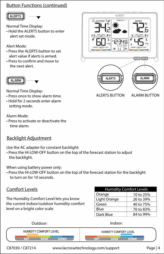
Normal Time Display:• Hold the ALERTS button to enter alert set mode.
Alert Mode: • Press the ALERTS button to set alert value if alerts is armed.• Press to confirm and move to the next alert.
Normal Time Display:• Press once to show alarm time.• Hold for 2 seconds enter alarm setting mode.
Alarm Mode:• Press to activate or deactivate the time alarm.
Backlight Adjustment
Use the AC adapter for constant backlight:• Press the HI-LOW-OFF button on the top of the forecast station to adjust the backlight.
When using battery power only:• Press the HI-LOW-OFF button on the top of the forecast station for the backlight to turn on for 10 seconds.
Comfort Levels
The Humidity Comfort Level lets you knowthe current indoor/outdoor humidity comfort level on a bright color scale.
Outdoor: Indoor:
Button Functions (continued)
ALERTS BUTTON ALARM BUTTON
Humidity Comfort LevelsOrangeLight OrangeGreenBlueDark Blue
10 to 25%26 to 39%40 to 75%76 to 83%84 to 99%
C87030 / C87214 www.lacrossetechnology.com/support Page | 4
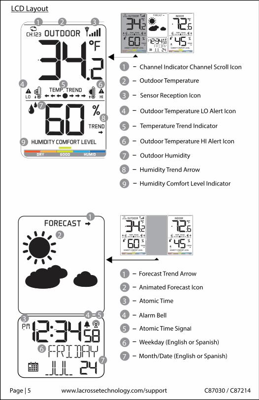
LCD Layout
1 2 3
4 5 6
7
8
9
1 Channel Indicator Channel Scroll Icon
2 Outdoor Temperature
3 Sensor Reception Icon
4
Outdoor Temperature HI Alert Icon
5 Temperature Trend Indicator
6
Outdoor Temperature LO Alert Icon
7
8
Outdoor Humidity
9
Humidity Trend Arrow
Humidity Comfort Level Indicator
1
2
3 4 5
67
1 Forecast Trend Arrow
2 Animated Forecast Icon
3 Atomic Time
4 Alarm Bell
5 Atomic Time Signal
6 Weekday (English or Spanish)
7 Month/Date (English or Spanish)
Page | 5 www.lacrossetechnology.com/support C87030 / C87214

Channel Indicator Channel Scroll Icon
Time Setting Order: 1. Beep On/Off 2. Atomic time signal (On/Off) 3. Time Zone 4. DST (Daylight Saving Time On/Off) 5. 12/24 hour time format 6. Hour 7. Minutes 8. Year 9. Month10. Date11. Fahrenheit/Celsius12. Language ENG-English or ESP-Spanish
Note: When Atomic OFF is selected, you skip items 3 and 4 and go straight to 12/24 hour time format
CSTMST
Time ZoneAtlanticEasternCentral
MountainPacificAlaska
Hawaiian
ASTEST
PSTAKTHAT
Note: Weekday will set automatically.
1
2 3
4
56
7
1 Indoor Temperature
2 Temperature Trend Indicator
3 Indoor Temperature HI Alert Icon
4 Indoor Humidity
5 Humidity Trend Arrow
6 Low Alert Symbol
Humidity Comfort Level Indicator7
• Hold the TIME SET button to enter settings menu.• Move through settings with the TIME SET button. • The and buttons will adjust settings.• Exit at anytime with SNOOZE/LIGHT button.
Instructions:
C87030 / C87214 www.lacrossetechnology.com/support Page | 6
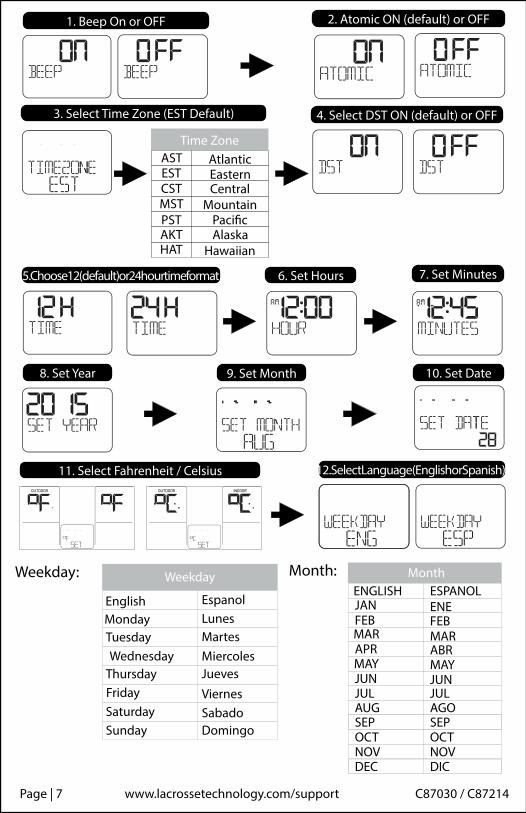
1. Beep On or OFF 2. Atomic ON (default) or OFF
3. Select Time Zone (EST Default)
CSTMST
Time ZoneAtlanticEasternCentral
MountainPacificAlaska
Hawaiian
ASTEST
PSTAKTHAT
4. Select DST ON (default) or OFF
5. Choose 12 (default) or 24 hour time format 6. Set Hours 7. Set Minutes
8. Set Year 9. Set Month 10. Set Date
11. Select Fahrenheit / Celsius 12. Select Language (English or Spanish)
TuesdayWednesday
Weekday
EspanolLunesMartesMiercolesJueves
ViernesSabado
EnglishMonday
ThursdayFridaySaturdaySunday Domingo
FEBMAR
MonthESPANOLENEFEBMARABRMAYJUN
ENGLISHJAN
APRMAYJUNJUL JULAUG AGOSEP SEPOCT OCTNOV NOVDEC DIC
Weekday: Month:
Page | 7 www.lacrossetechnology.com/support C87030 / C87214
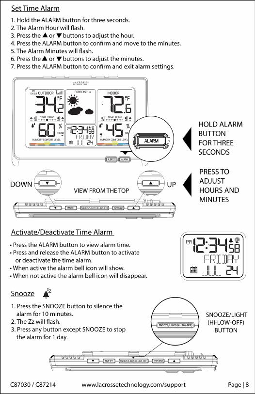
1. Hold the ALARM button for three seconds.2. The Alarm Hour will flash.3. Press the or buttons to adjust the hour.4. Press the ALARM button to confirm and move to the minutes.5. The Alarm Minutes will flash.6. Press the or buttons to adjust the minutes.7. Press the ALARM button to confirm and exit alarm settings.
Set Time Alarm
UPDOWNVIEW FROM THE TOP
HOLD ALARM BUTTONFOR THREE SECONDS
PRESS TO ADJUST HOURS AND MINUTES
Activate/Deactivate Time Alarm
• Press the ALARM button to view alarm time.• Press and release the ALARM button to activate or deactivate the time alarm.• When active the alarm bell icon will show. • When not active the alarm bell icon will disappear.
Snooze
1. Press the SNOOZE button to silence the alarm for 10 minutes.2. The Zz will flash. 3. Press any button except SNOOZE to stop the alarm for 1 day.
SNOOZE/LIGHT(HI-LOW-OFF)
BUTTON
C87030 / C87214 www.lacrossetechnology.com/support Page | 8
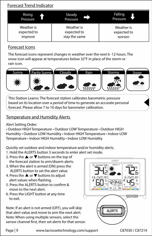
Alert Setting Order:• Outdoor HIGH Temperature • Outdoor LOW Temperature • Outdoor HIGH Humidity • Outdoor LOW Humidity • Indoor HIGH Temperature • Indoor LOW Temperature • Indoor HIGH Humidity • Indoor LOW Humidity
Quickly set outdoor and indoor temperature and/or humidity alerts.1. Hold the ALERTS button 3 seconds to enter alert set mode. 2. Press the or buttons on the top of the forecast station to arm/disarm alerts.3. When the alert is armed (ON) press the ALERTS button to set the alert value. 4. Press the or buttons to adjust alert values when flashing.5. Press the ALERTS button to confirm & move to the next alert.6. Press the LIGHT button at any time to exit.
Note: If an alert is not armed (OFF), you will skip that alert value and move to arm the next alert.Note: When using multiple sensors, select thesensor channel first, then set alerts for that sensor.
Forecast IconsThe forecast icons represent changes in weather over the next 6 -12 hours. The snow icon will appear at temperatures below 32°F in place of the storm or rain icon.
Partly Sunny
Forecast Trend Indicator
Rising Pressure
SteadyPressure
FallingPressure
Weather is expected to
improve
Weather is expected to
stay the same
Weather is expected to
worsen
Temperature and Humidity Alerts
This Station Learns: The forecast station calibrates barometric pressure based on its location over a period of time to generate an accurate personal forecast. Please allow 7 to 10 days for barometer calibration.
SnowStormyCloudyPartly SunnySunny Rain
Page | 9 www.lacrossetechnology.com/support C87030 / C87214

1. Hold the ALERTS button to enter alert set mode. 2. Default is OFF. Use or to turn ON (arm) then set alert value.
3. If you do not arm the alert, you will skip that alert value and move to the next alert option.
4. If you select ON (armed) you will move to set the alert value.
5. Press the or buttons to adjust alert value when flashing.6. Press the ALERTS button to confirm & move to the next alert.
Temperature Trend Indicators
The temperature (2°F / 1°C) trend indicators update every 30 minutes.• 3 hrs. increments which changes on every ½ hour e.g.: At 3:00 — compares to 12:00 data; at 3:30 — compares to 12:30, etc.
Rising Scrolls Right
FallingScrolls Left
SteadyNo Scroll
Three arrows will scroll right when temperature is rising, and scroll left when temperature is falling. When there is no change in temperature one right and one left arrow will show.
Set Alerts
DEFAULT (OFF) TURN ON WITH
DEFAULT (OFF) DEFAULT (OFF) TURN ON WITH
DEFAULT (OFF) TURN ON WITH
C87030 / C87214 www.lacrossetechnology.com/support Page | 10
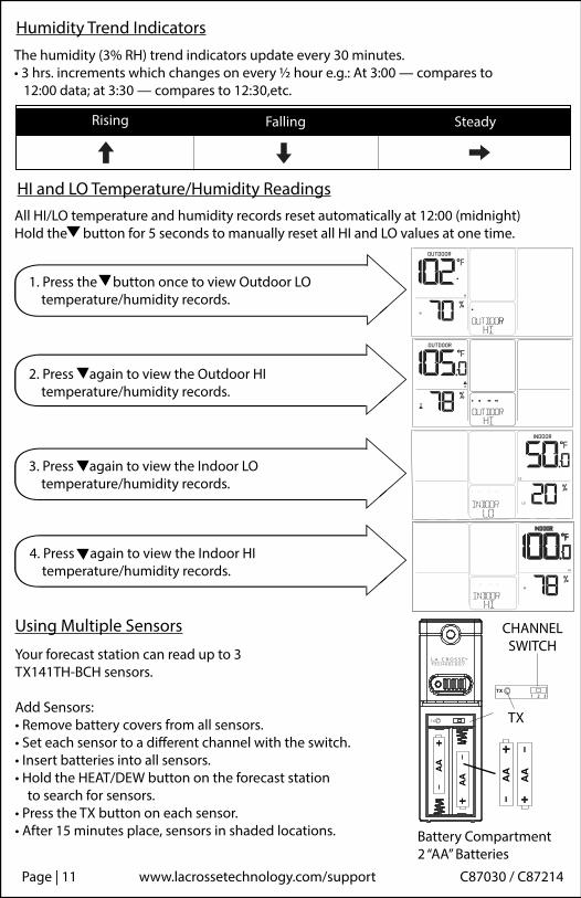
Using Multiple Sensors
Your forecast station can read up to 3TX141TH-BCH sensors.
Add Sensors: • Remove battery covers from all sensors.• Set each sensor to a different channel with the switch.• Insert batteries into all sensors.• Hold the HEAT/DEW button on the forecast station to search for sensors.• Press the TX button on each sensor.• After 15 minutes place, sensors in shaded locations.
1 2 3
AA
AA AA
AA
TX
CHANNEL SWITCH
Battery Compartment2 “AA” Batteries
1. Press the button once to view Outdoor LO temperature/humidity records.
HI and LO Temperature/Humidity ReadingsAll HI/LO temperature and humidity records reset automatically at 12:00 (midnight)Hold the button for 5 seconds to manually reset all HI and LO values at one time.
2. Press again to view the Outdoor HI temperature/humidity records.
3. Press again to view the Indoor LO temperature/humidity records.
4. Press again to view the Indoor HI temperature/humidity records.
Humidity Trend Indicators
Rising Falling Steady
The humidity (3% RH) trend indicators update every 30 minutes. • 3 hrs. increments which changes on every ½ hour e.g.: At 3:00 — compares to 12:00 data; at 3:30 — compares to 12:30,etc.
Page | 11 www.lacrossetechnology.com/support C87030 / C87214
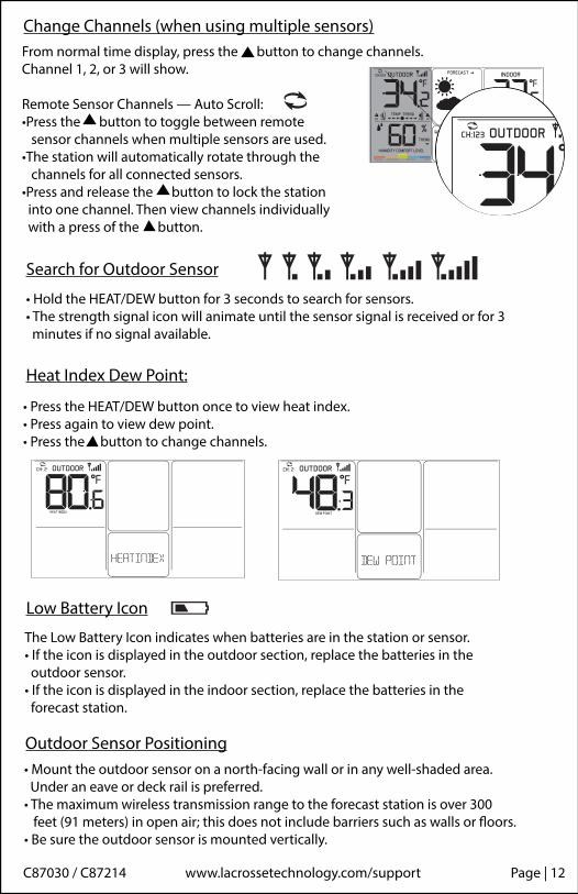
Search for Outdoor Sensor
• Hold the HEAT/DEW button for 3 seconds to search for sensors.• The strength signal icon will animate until the sensor signal is received or for 3 minutes if no signal available.
Change Channels (when using multiple sensors)From normal time display, press the button to change channels.Channel 1, 2, or 3 will show.
Remote Sensor Channels — Auto Scroll:•Press the button to toggle between remote sensor channels when multiple sensors are used. •The station will automatically rotate through the channels for all connected sensors. •Press and release the button to lock the station into one channel. Then view channels individually with a press of the button.
Low Battery Icon
The Low Battery Icon indicates when batteries are in the station or sensor.• If the icon is displayed in the outdoor section, replace the batteries in the outdoor sensor.• If the icon is displayed in the indoor section, replace the batteries in the forecast station.
Heat Index Dew Point:
Outdoor Sensor Positioning• Mount the outdoor sensor on a north-facing wall or in any well-shaded area. Under an eave or deck rail is preferred. • The maximum wireless transmission range to the forecast station is over 300 feet (91 meters) in open air; this does not include barriers such as walls or floors.• Be sure the outdoor sensor is mounted vertically.
• Press the HEAT/DEW button once to view heat index.• Press again to view dew point.• Press the button to change channels.
C87030 / C87214 www.lacrossetechnology.com/support Page | 12

Care and Maintenance• Do not mix old and new batteries• Do not mix Alkaline, Standard, Lithium or Rechargeable Batteries• Always purchase the correct size and grade of battery most suitable for intended use.• Replace all batteries of a set at the same time.• Clean the battery contacts and also those of the device prior to battery installation.• Ensure the batteries are installed with correct polarity ( + and - ).• Remove batteries from equipment which is not to be used for an extended period of time.• Remove expired batteries promptly.
La Crosse Technology, Ltd. provides a 1-year limited time warranty (from date of purchase) on this product relating to manufacturing defects in materi-als & workmanship.
Before returning a product, please contact our friendly customer support with questions or visit our online help (FAQS):
Phone: 1-877-408-2678Online Product Support: www.lacrossetechnology.com/support Product Registration: www.lacrossetechnology.com/support/register View full warranty details online at: www.lacrossetechnology.com/warranty_info.pdf Warranty Address: Protected under U.S. Patents:La Crosse Technology, Ltd. 5,978,738 | 6,076,044 | RE439032830 S. 26th St.La Crosse, WI 54601
Warranty and Support Information
• From normal time display press the TIME SET button once to search for the WWVB time signal.• For information about WWVB visit: http://www.nist.gov/pml/div688/grp40/wwvb.cfm.
WWVB Atomic Time Signal Search Atomic Icon
Restart When the outdoor readings show dashes: • Bring the sensor in the house at least five feet from the forecast station.• Remove batteries from the sensor, as well as, the batteries and AC adapter from the forecast station.• Press any button 20 times.• After 15 minutes insert batteries into the sensor and station and re-connect the adapter. • Wait 15 minutes to establish a strong connection. Place sensor outside in shaded location.
Page | 13 www.lacrossetechnology.com/support C87030 / C87214
When the outdoor readings show dashes: • Bring the sensor in the house at least five feet from the forecast station.• Remove batteries from the sensor, as well as, the batteries and AC adapter from the forecast station.• Press any button 20 times.• After 15 minutes insert batteries into the sensor and station and re-connect the adapter. • Wait 15 minutes to establish a strong connection. Place sensor outside in shaded location.
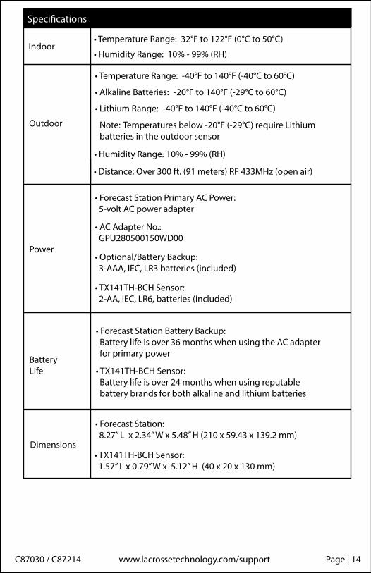
Indoor• Temperature Range: 32°F to 122°F (0°C to 50°C)
• Humidity Range: 10% - 99% (RH)
Outdoor
• Temperature Range: -40°F to 140°F (-40°C to 60°C)
• Alkaline Batteries: -20°F to 140°F (-29°C to 60°C)
• Lithium Range: -40°F to 140°F (-40°C to 60°C)
Note: Temperatures below -20°F (-29°C) require Lithium batteries in the outdoor sensor
• Humidity Range: 10% - 99% (RH)
• Distance: Over 300 ft. (91 meters) RF 433MHz (open air)
Power
• Forecast Station Primary AC Power: 5-volt AC power adapter
• AC Adapter No.: GPU280500150WD00
• Optional/Battery Backup: 3-AAA, IEC, LR3 batteries (included)
BatteryLife
• TX141TH-BCH Sensor: 2-AA, IEC, LR6, batteries (included)
• Forecast Station Battery Backup: Battery life is over 36 months when using the AC adapter for primary power
Dimensions
• Forecast Station: 8.27” L x 2.34” W x 5.48” H (210 x 59.43 x 139.2 mm)
• TX141TH-BCH Sensor: 1.57” L x 0.79” W x 5.12” H (40 x 20 x 130 mm)
Specifications
• TX141TH-BCH Sensor: Battery life is over 24 months when using reputable battery brands for both alkaline and lithium batteries
C87030 / C87214 www.lacrossetechnology.com/support Page | 14
FCC Statement
Caution!
This equipment has been tested and found to comply with the limits for a Class B digital device, pursuant to part 15 of the FCC Rules. These limits are designed to provide reasonable protection against harmful interference in a residential installation. This equipment generates, uses and can radiate radio frequency energy and, if not installed and used in accordance with the instructions, may cause harmful interference to radio communications. However, there is no guarantee that interference will not occur in a particu-lar installation. If this equipment does cause harmful interference to radio or television reception, which can be determined by turning the equipment off and on, the user is encouraged to try to correct the interference by one or more of the following measures:
• Reorient or relocate the receiving antenna. • Increase the separation between the equipment and receiver. • Connect the equipment into an outlet on a circuit different from that to which the receiver is connected. • Consult the dealer or an experienced radio/TV technician for help.
This device must not be co-located or operating in conjunction with any other antenna or transmitter. Operation is subject to the following two conditions: (1) this device may not cause harmful interference, and (2) this device must accept any interference received, including interference that may cause undesired operation.
The manufacturer is not responsible for any radio or TV interference caused by unauthorized modifications to this equipment. Such modifications could void the user authority to operate the equipment.
All rights reserved. This manual may not be reproduced in any form, even in part, or duplicated or processed using electronic, mechanical or chemical process without the written permission of the publisher.
This booklet may contain errors or misprints. The information it contains is regularly checked and corrections are included in subsequent editions. We disclaim any responsibility for any technical error or printing error, or their consequences.
All trademarks and patents are recognized.
Page | 1 5 www.lacrossetechnology.com/support C87030 / C87214