wide-field wide-band full-mueller imaging · wide-field wide-band full-mueller imaging calim2016,...
TRANSCRIPT

Wide-field Wide-band Full-Mueller Imaging
CALIM2016, Oct. 10th 2016, Socorro, NM
S. BhatnagarNRAO, Socorro

2/23S. Bhatnagar: CALIM 2016, Socorro, NM, Oct. 10th 2016
The Scientific Motivation
• Most projects with current telescopes require precise reconstruction of the sky brightness distribution.
– Continuum science; High DR imaging
– Polarimetry; High fidelity
– Wide-band data: spectral index, RM mapping
– All of the above for mosaic imaging
Range of use cases
3/23S. Bhatnagar: CALIM 2016, Socorro, NM, Oct. 10th 2016
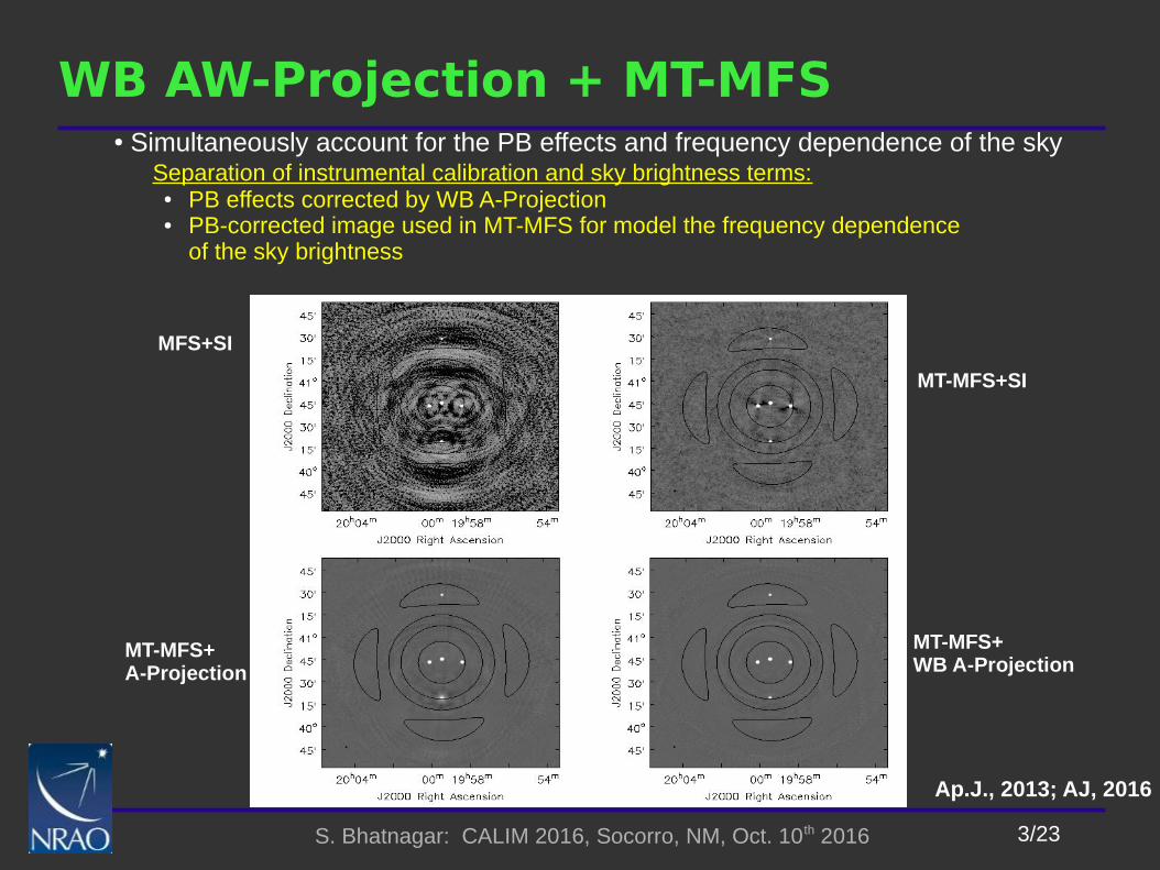
WB AW-Projection + MT-MFS● Simultaneously account for the PB effects and frequency dependence of the sky Separation of instrumental calibration and sky brightness terms:
● PB effects corrected by WB A-Projection● PB-corrected image used in MT-MFS for model the frequency dependence
of the sky brightness
MFS+SI
MT-MFS+A-Projection
MT-MFS+WB A-Projection
MT-MFS+SI
Ap.J., 2013; AJ, 2016
4/23S. Bhatnagar: CALIM 2016, Socorro, NM, Oct. 10th 2016
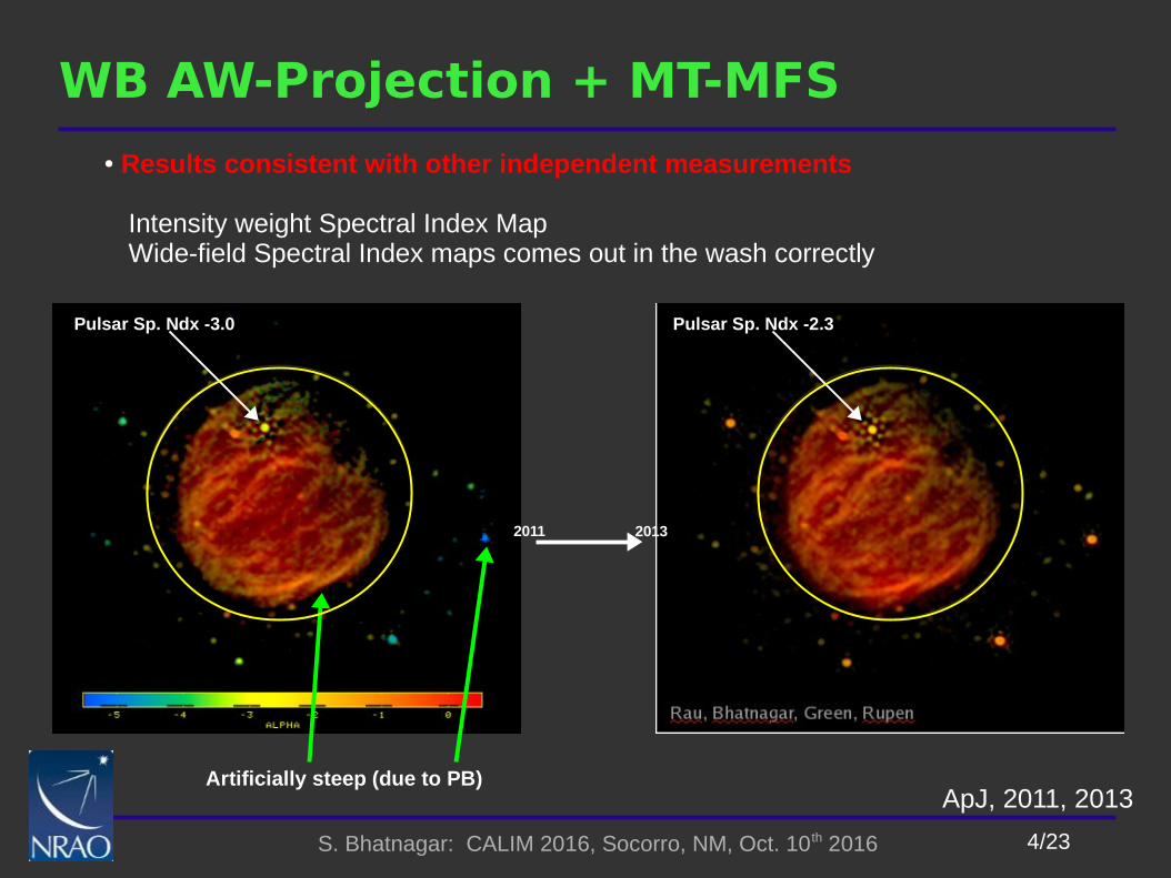
WB AW-Projection + MT-MFS
ApJ, 2011, 2013
Pulsar Sp. Ndx -3.0 Pulsar Sp. Ndx -2.3
● Results consistent with other independent measurements
Intensity weight Spectral Index Map Wide-field Spectral Index maps comes out in the wash correctly
Artificially steep (due to PB)
2011 2013
5/23S. Bhatnagar: CALIM 2016, Socorro, NM, Oct. 10th 2016
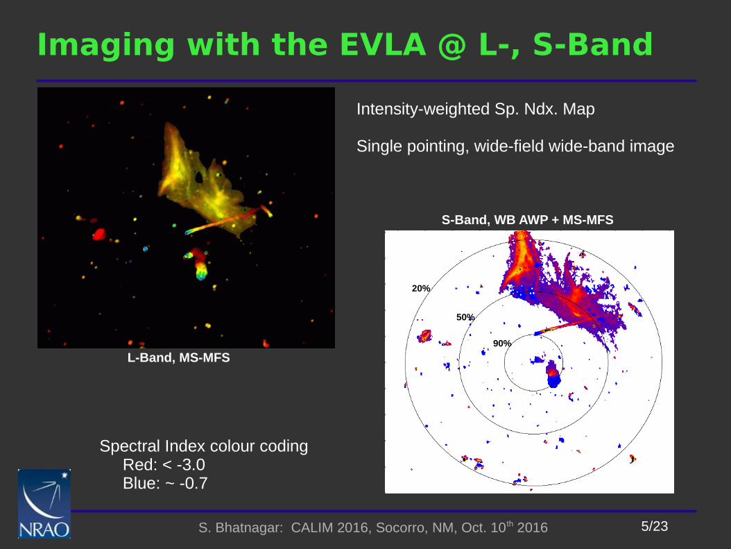
Imaging with the EVLA @ L-, S-Band
Intensity-weighted Sp. Ndx. Map
Single pointing, wide-field wide-band image
L-Band, MS-MFS
S-Band, WB AWP + MS-MFS
Spectral Index colour coding Red: < -3.0 Blue: ~ -0.7
20%
50%
90%
6/23S. Bhatnagar: CALIM 2016, Socorro, NM, Oct. 10th 2016
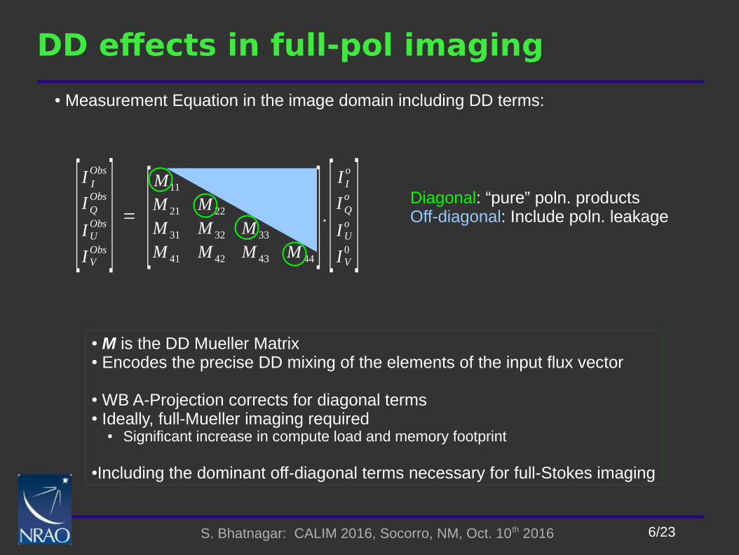
DD effects in full-pol imaging
[I I
Obs
IQObs
IUObs
I VObs ] = [
M11 M 12 M 13 M 14
M 21 M 22 M 23 M 24
M 31 M 32 M 33 M 34
M 41 M 42 M 43 M 44] .[
I Io
IQo
IUo
I V0 ] Diagonal: “pure” poln. products
Off-diagonal: Include poln. leakage
● Measurement Equation in the image domain including DD terms:
● M is the DD Mueller Matrix● Encodes the precise DD mixing of the elements of the input flux vector
● WB A-Projection corrects for diagonal terms● Ideally, full-Mueller imaging required
● Significant increase in compute load and memory footprint
●Including the dominant off-diagonal terms necessary for full-Stokes imaging
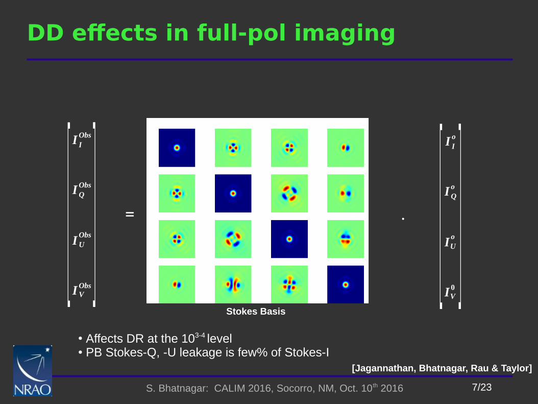
7/23S. Bhatnagar: CALIM 2016, Socorro, NM, Oct. 10th 2016
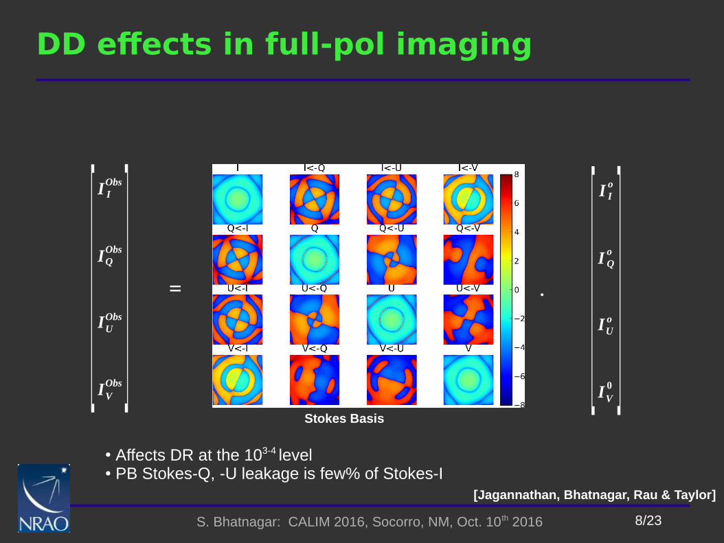
DD effects in full-pol imaging
Stokes Basis
. [I I
o
IQo
IUo
IV0
][I I
Obs
IQObs
IUObs
IVObs
] =
● Affects DR at the 103-4 level● PB Stokes-Q, -U leakage is few% of Stokes-I
[Jagannathan, Bhatnagar, Rau & Taylor]
8/23S. Bhatnagar: CALIM 2016, Socorro, NM, Oct. 10th 2016
DD effects in full-pol imaging
Stokes Basis
. [I I
o
IQo
IUo
IV0
][I I
Obs
IQObs
IUObs
IVObs
] =
● Affects DR at the 103-4 level● PB Stokes-Q, -U leakage is few% of Stokes-I
[Jagannathan, Bhatnagar, Rau & Taylor]
9/23S. Bhatnagar: CALIM 2016, Socorro, NM, Oct. 10th 2016
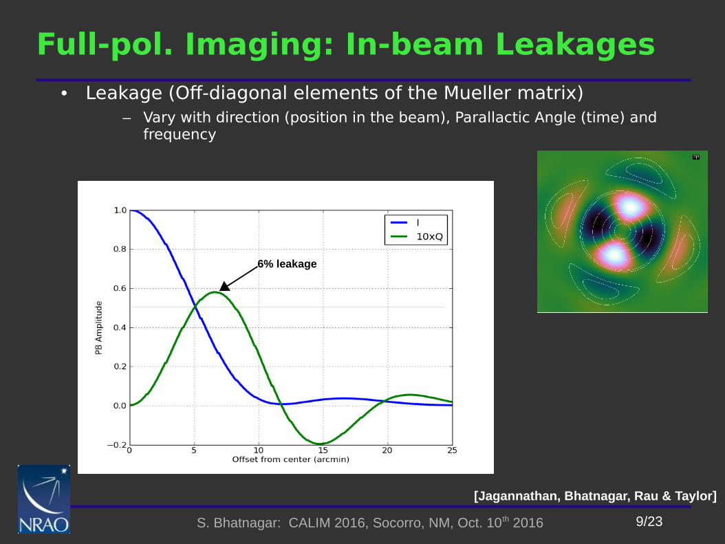
Full-pol. Imaging: In-beam Leakages
• Leakage (Off-diagonal elements of the Mueller matrix)– Vary with direction (position in the beam), Parallactic Angle (time) and
frequency
[Jagannathan, Bhatnagar, Rau & Taylor]
Radial Slice for Stokes-I and I->Q Leakage
6% leakage

10/23S. Bhatnagar: CALIM 2016, Socorro, NM, Oct. 10th 2016
Issues in Wide-field Wide-band Full-Pol. Imaging
• PB Effects– In-beam effects : DD Leakage
– Parametric Aperture Illumination model (Holographic measurements not sufficient)
– Pointing Errors
– Mosaic patterns
• Variations with frequency– Frequency dependence of intrinsic Q and U
– Frequency dependence due to PB
• Computing load– More expensive: Fundamentally need more CF pixels for wide-field
imaging
– Larger memory footprint: Fundamentally, any which way you cut it
11/23S. Bhatnagar: CALIM 2016, Socorro, NM, Oct. 10th 2016
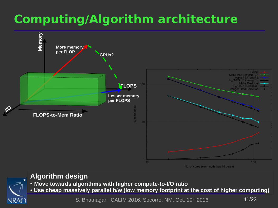
Computing/Algorithm architecture
FLOPS
I/O
Mem
ory
FLOPS-to-Mem Ratio
More memory per FLOP
Lesser memory per FLOPS
GPUs?
Algorithm design● Move towards algorithms with higher compute-to-I/O ratio● Use cheap massively parallel h/w (low memory footprint at the cost of higher computing)
12/23S. Bhatnagar: CALIM 2016, Socorro, NM, Oct. 10th 2016
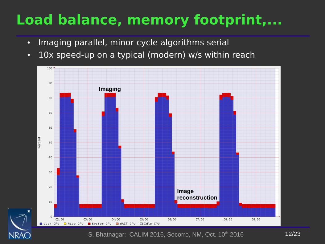
Load balance, memory footprint,...
• Imaging parallel, minor cycle algorithms serial
• 10x speed-up on a typical (modern) w/s within reach
Imaging
Image reconstruction
13/23S. Bhatnagar: CALIM 2016, Socorro, NM, Oct. 10th 2016
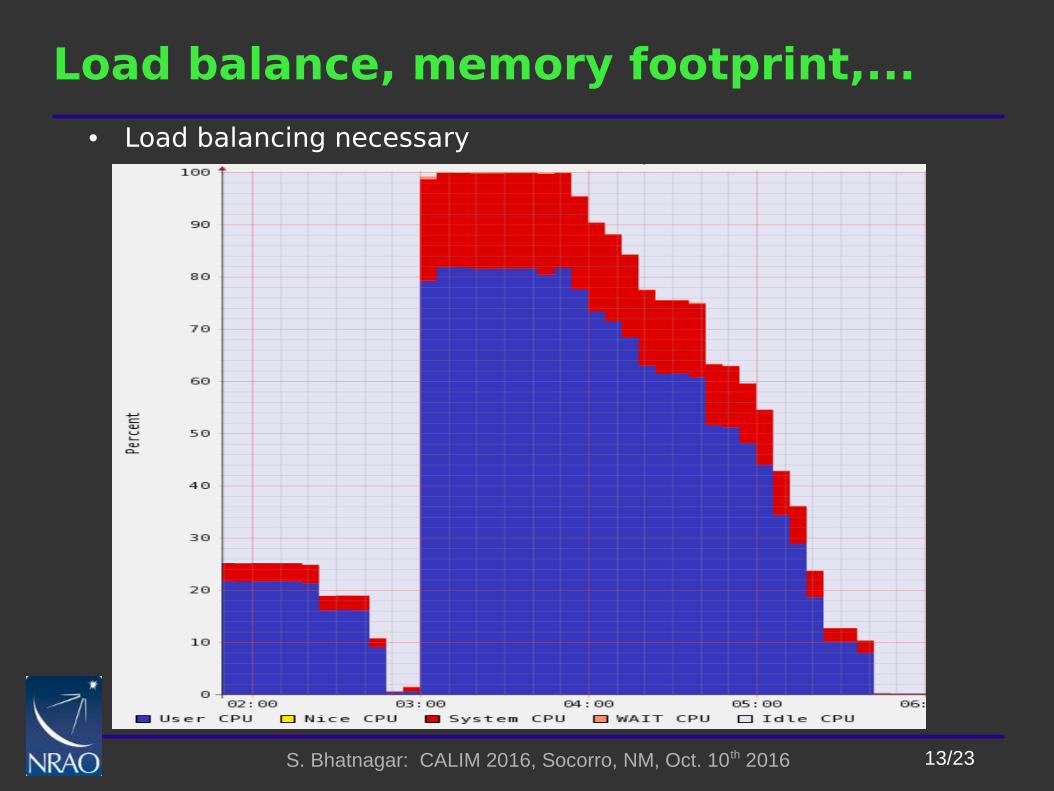
Load balance, memory footprint,...
• Load balancing necessary
14/23S. Bhatnagar: CALIM 2016, Socorro, NM, Oct. 10th 2016
Load balance, memory footprint,...
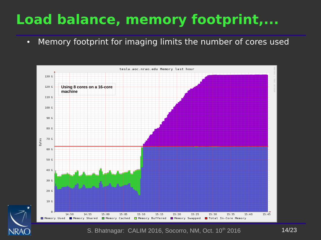
• Memory footprint for imaging limits the number of cores used
Using 8 cores on a 16-coremachine

15/23S. Bhatnagar: CALIM 2016, Socorro, NM, Oct. 10th 2016
Load balance, memory footprint,...
• Memory footprint for imaging limits the number of cores used
Using 8 cores on a 16-coremachine
With memory management

16/23S. Bhatnagar: CALIM 2016, Socorro, NM, Oct. 10th 2016
All PB effects together
RR
LL
Fre
qu
ency
Po
ln.
Poln. squint
Freq. scaling

17/23S. Bhatnagar: CALIM 2016, Socorro, NM, Oct. 10th 2016
DD Calibration
• Wide-band Full-Pol. A(W)-Projection
• DD Jones Matrix: Each term is a complex gain pattern (a 2D function)
– Antenna off-axis gains and polarization leakages
FT (Ai) =
ER
EL
Off-axis leakage
Off-axis leakage
V ijObs
= [ Ai⊗A jT ] ∗[V ij
o ] = [ Aij ] ∗[V ijo ]
V ijCorr = [ A ij
MT
∗Aij ]∗[V ijObs ]
● Requires a model for the antenna aperture illumination
● Wide-band and up-to at least first sidelobe
18/23S. Bhatnagar: CALIM 2016, Socorro, NM, Oct. 10th 2016
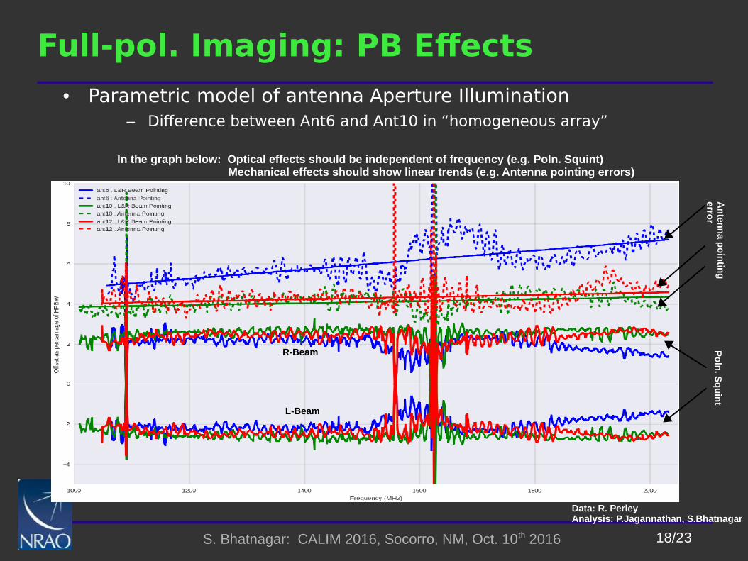
Full-pol. Imaging: PB Effects
• Parametric model of antenna Aperture Illumination– Difference between Ant6 and Ant10 in “homogeneous array”
R-Beam
L-Beam
Data: R. PerleyAnalysis: P.Jagannathan, S.Bhatnagar
In the graph below: Optical effects should be independent of frequency (e.g. Poln. Squint) Mechanical effects should show linear trends (e.g. Antenna pointing errors)
Po
ln. S
qu
int
An
tenn
a po
intin
gerro
r
19/23S. Bhatnagar: CALIM 2016, Socorro, NM, Oct. 10th 2016
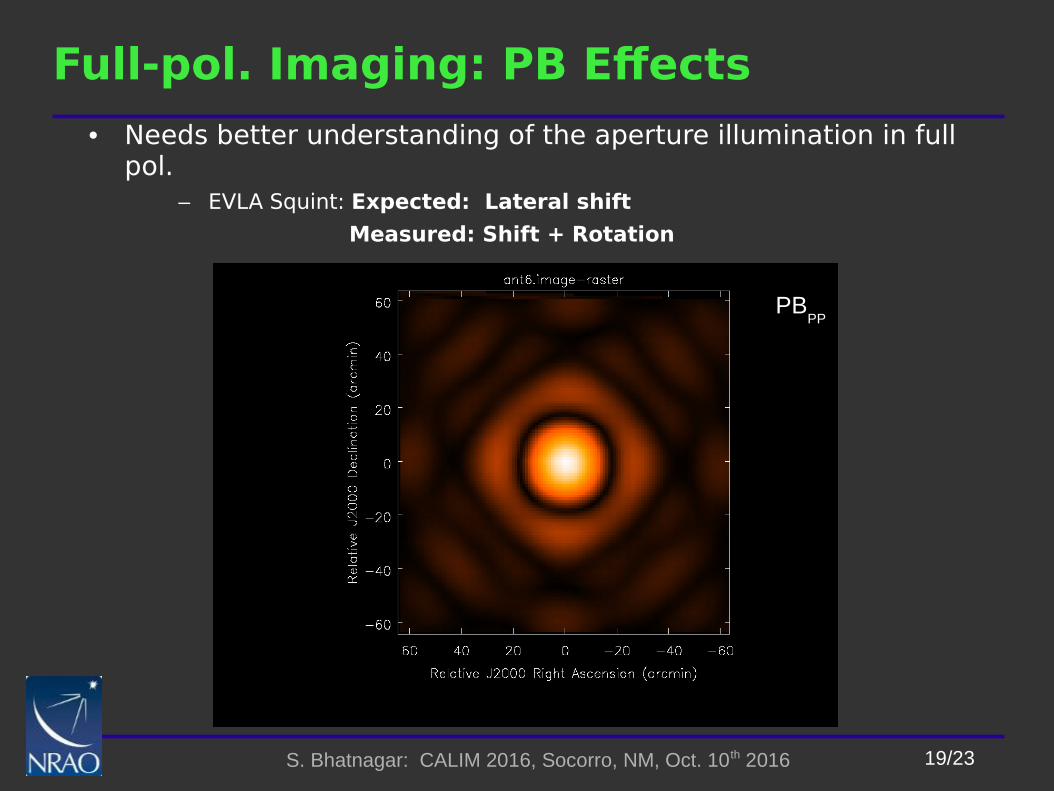
Full-pol. Imaging: PB Effects
• Needs better understanding of the aperture illumination in full pol.
– EVLA Squint: Expected: Lateral shift
Measured: Shift + Rotation
PB
PP
20/23S. Bhatnagar: CALIM 2016, Socorro, NM, Oct. 10th 2016
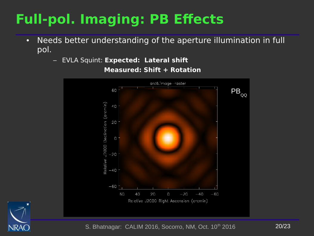
Full-pol. Imaging: PB Effects
• Needs better understanding of the aperture illumination in full pol.
– EVLA Squint: Expected: Lateral shift
Measured: Shift + Rotation
PB

21/23S. Bhatnagar: CALIM 2016, Socorro, NM, Oct. 10th 2016
Full-pol. Imaging: Mosaic Sensitivity Pattern
[Jagannathan, Bhatnagar, Rau & Taylor]
In-beam Stokes-Q pattern for a 11x11 point mosaick
● In-beam DD leakage spreads all across the mosaicked region. ● Rotation due to PA change ignored
● The resulting pattern is combination of overlapping Clover-leaf pattern of each pointing

22/23S. Bhatnagar: CALIM 2016, Socorro, NM, Oct. 10th 2016
Take away-1
• Projection algorithms are true DD generalization of DI algorithms– Need good models for the antenna aperture illumination patterns
– Holographic measurements
• Computing architecture – Scale-able: Harder than appears in paper designs; Domain expertise crucial
– Extensible : Needed functionality will be spread over time and people
– Configurable: Watch out for the curse of Amdahl’s Law; resource balancing
– Capable of utilizing heterogeneous platforms
• Develop human resource: People with multidisciplinary skills, without mental-block for simple math., rigor, tenacity
– Capable of enjoying all of the above!

23/23S. Bhatnagar: CALIM 2016, Socorro, NM, Oct. 10th 2016
Take away-2
• WB A(W)-Projection + MT-MFS in CASA under commissioning
• Architecture allows use of beam models, full/partial-Mueller matrix, heterogeneous arrays (not tested yet), mosaic imaging and correction for pointing errors (not tested).
• Errors due to DD leakage can be 100% for Q- and U-images
• Work in advanced stage for testing Mueller imaging with WB EVLA data (Preshanth’s thesis)
• HPC completely integrated with all of the above– Parallel CF computation, imaging, memory management
– Measured to be close to linear scaling
• Full-pol corrections even more important for mosaic imaging