wgn docs-#153533-v1-erosion and sediment control ... · erosion and sediment control guidelines for...
TRANSCRIPT

Erosion and Sediment Control Guidelines for the Wellington Region
Greater Wellington – The Regional Council i
Erosion and Sediment Control Guidelines for the Wellington Region September 2002 Reprinted June 2006
Erosion and Sediment Control Guidelines for the Wellington Region
ii Greater Wellington – The Regional Council
CONTENTS
1. OBJECTIVES 1.1 Intent of these Guidelines 1 1.2 When is Erosion and Sediment Control Required? 2 1.3 When are Resource Consents Required? 2 1.4 Why Erosion and Sediment Control is Necessary? 2 1.5 Wellington’s Soils 3
2. UNDERSTANDING EROSION 7 2.1 Introduction 7 2.2 Factors Influencing the Erosion Process 7 2.2.1 Climate 7 2.2.2 Soil Characteristics 8 2.2.3 Topography 8 2.2.4 Ground Cover 8 2.2.5 Evapotranspiration 9
3. THE PRINCIPLES OF EROSION AND SEDIMENT CONTROL 11 3.1 Minimise Disturbance 11 3.2 Stage Construction 11 3.3 Protect Steep Slopes 11 3.4 Protect Waterbodies 11 3.5 Stabilise Exposed Areas Rapidly 11 3.6 Install Perimeter Controls 12 3.7 Employ Detention Devices 12 3.8 Make Sure the Plan Evolves 12 3.9 Inspect 12
4. EROSION CONTROL MEASURES 13 4.1 Runoff Diversion Channel/Bund 13 4.2 Contour Drain 16 4.3 Rock Check Dam 19 4.4 Level Spreader 22 4.5 Pipe Drop Structure / Flume 25 4.6 Benched Slope 29 4.7 Surface Roughening 32 4.8 Stabilised Construction Entrance 34 4.9 Geosynthetic Erosion Control Systems (GECS) 36 4.10 Revegetation Techniques 39 4.10.1 Top Soiling 39 4.10.2 Temporary and Permanent Seeding 40 4.10.3 Hydroseeding 41 4.10.4 Mulching 43 4.10.5 Turfing 45
5. SEDIMENT CONTROL MEASURES 49 5.1 Sediment Retention Pond 50 5.2 Chemical Flocculation Systems 61 5.3 Silt Fence 70 5.4 Super Silt Fence 74 5.5 Stormwater Inlet Protection 77 5.6 Decanting Earth Bund 80

Erosion and Sediment Control Guidelines for the Wellington Region
Greater Wellington – The Regional Council iii
5.7 Decanting Topsoil Bund 82 5.8 Sump / Sediment Pit 84
6. WORKS IN WATERBODIES Error! Bookmark not defined. 6.1 Temporary Waterbody Diversions 87 6.2 Temporary Waterbody Crossings 91
7. QUARRIES Error! Bookmark not defined. 7.1 Road Access 93 7.2 Stormwater 93 7.2.1 Clean Runoff 93 7.2.2 Contaminated Runoff 94 7.3 Overburden Disposal 94 7.4 Stockpile Areas 94 7.5 Rehabilitation of Worked Out Areas 94 7.6 Riparian Protection Areas 95 7.7 Maintenance Schedule for Erosion and Sediment Control or Treatment Structures 95
8. FORESTRY OPERATIONS 96 8.1 Roading 96 8.1.1 Planning, Location and Design 96 8.1.2 Construction 96 8.2 Firebreaks 97 8.3 Land Preparation 97 8.3.1 Planning 97 8.3.2 Protection Areas (Riparian Margins) 97 8.3.3 Planting Boundaries 98 8.3.4 V-Blading/Line Raking 98 8.3.5 Establishing and Tending 98 8.4 Harvesting and Management After Harvesting 98 8.4.1 Planning of Logging Operations 98 8.4.2 Felling Operations 98 8.4.3 Extraction Operations 99 8.4.4 Cleanup Operations 99 8.5 Landings and Tracks 99
9. OTHER TYPES of land disturbing activities 101 9.1 Trenching 101 9.2 Cleanfills 101 9.3 Small Sites 101 9.4 Roading 102
10. GLOSSARY 103
11. BIBLIOGRAPHY 115

Erosion and Sediment Control Guidelines for the Wellington Region
iv Greater Wellington - The Regional Council
Acknowledgements Greater Wellington – The Regional Council wishes to thank the Auckland Regional Council for their kind permission to re-produce parts of Technical Publication 90 - Erosion and Sediment Control Guidelines for Land Disturbing Activities used in the making of this publication.
Thanks to Babington & Associates Ltd. for providing technical advice.
Erosion and Sediment Control Guidelines for the Wellington Region
Greater Wellington – The Regional Council 1
1. Objectives
1.1 Intent of these Guidelines These Guidelines are a non-statutory document. They are intended to assist all persons working in earthwork situations with implementing methods and devices for minimising erosion and sedimentation. Although the methods and devices represent current best practice, other effective controls may exist that could suit the topography of specific sites. Furthermore, it is expected that as the engineering science of erosion and sediment control is advanced, there may be refinements of existing methods for achieving erosion and sediment control and new methods developed. Therefore the Guidelines should be seen as a ‘living’ document and may be subject to future revision.
These Guidelines have the following objectives:
• To provide users with a series of comprehensive guidelines for erosion and sediment control for land disturbing activities.
• To minimise adverse environmental effects of land disturbing activities through appropriate use and design of erosion and sediment control techniques.
• Assist applicants for earthworks resource consents who are considering appropriate measures to mitigate erosion and sedimentation.
• Promote full compliance with resource consent conditions.
• Promote full compliance with permitted activity standards.
• The Guidelines should be used during the development of an Erosion and Sediment Control Plan for a project and may also be used when operating under the conditions of an approved consent.
Greater Wellington staff are available for further advice and can be contacted at: Regional Council Centre 142-146 Wakefield Street PO Box 11-646 Wellington Telephone: 04-384 5708 or Regional free-phone 04-384 5707, or 0800 496 734 Facsimile: 04-385 6960 Email: [email protected] website: http://www.gw.govt.nz/ Or Chapel Street PO Box 41 Masterton Telephone: 06-378 2484 Facsimile: 06-378 2146

Erosion and Sediment Control Guidelines for the Wellington Region
2 Greater Wellington - The Regional Council
1.2 When is Erosion and Sediment Control Required?
All projects involving land disturbing activities in the Wellington Region should incorporate erosion and sediment controls as an integral part of development. This includes any earthworks, cleanfills, landfills and quarrying and forestry operations. Activities in waterbodies may also benefit from erosion and sediment control and these Guidelines include a number of erosion and sediment control measures that can be used for waterbody realignment, piping, culverting and stabilisation works.
On projects involving land disturbance, erosion and sediment controls should be in place before bulk earthworks commence and should be removed only after the site has been fully stabilised to protect it from erosion. The principles and practices within these Guidelines should be referred to and staff at the Greater Wellington, or the relevant city or district council, contacted for further advice if required.
1.3 When are Resource Consents Required? The Regional Soil Plan for the Wellington Region (October 2000) and the district plans of each district or city council set out when a land use consent for soil disturbance is required.
The rules in the Regional Soil Plan for the Wellington Region apply only to land disturbing activities on erosion prone land, roading and tracking activities and vegetation disturbance. Silt-contaminated discharges to natural water may also require resource consent. The Regional Freshwater Plan for the Wellington Region (December 1999) explains when a discharge permit is required for silted stormwater. Application forms for these consents can be obtained by contacting Greater Wellington.
The rules relating to land disturbance in the district plans of each district or city council vary. Therefore if you are uncertain of the rules, you should contact the appropriate city or district council before undertaking any land disturbing activities. Generally, district plans contain rules relating to land disturbance on all land, not just erosion prone land and these rules relate to activities such as subdivision, building construction, roading and tracking, cleanfills and landfills.
1.4 Why Erosion and Sediment Control is Necessary? Many hectares of land are stripped of vegetation or laid bare each year in the Wellington Region for the construction of subdivisions, roads and other developments. Without protection measures, the transformation of this land can result in accelerated on-site erosion and greatly increased sedimentation of waterbodies such as rivers, estuaries and harbours.
Significant quantities of sediment may be discharged from bare earth surfaces where appropriate erosion and sediment control measures are not implemented.
Studies in other regions such as Auckland indicate there is a 10 to 100 fold increase in sediment yield from construction sites compared with pastoral land. Data from the United States suggests that there may be up to 1000 times the sediment yield from disturbed sites during construction compared with permanent forest cover.
Erosion and Sediment Control Guidelines for the Wellington Region
Greater Wellington – The Regional Council 3
Possible environmental effects associated with sediment release are well documented and include:
• smothering of aquatic life by a build-up of sediment in the stream bed
• alteration of habitats (for example, by destroying spawning grounds)
• abrasive action against aquatic life (for example, increasing susceptibility to disease)
• scouring of algae (a major food supply for stream life) from rocks in the stream bed
• changes to predator-prey relationships due to increased turbidity (cloudiness) in the water, stopping animals feeding because they cannot see their prey
• changes to temperature due to increases in turbidity affecting heat absorption
• reduce primary productivity due to increases in turbidity stopping light penetrating the water, slowing down photosynthetic activity and subsequent plant and algae growth
• accumulation of pollutants transported by sediments (for example, lead, hydrocarbons, agricultural nutrients and toxic substances)
• blockage of water flows, increasing susceptibility to flooding and consequent damage to property
• effects on consumable water for irrigation, stock and domestic water supplies (for example, clogging of pumps, filters and sprinkle nozzles and increasing
• reduced aesthetic quality of water bodies
There is more often a total change to in-stream communities. Recovery times from the impacts of sediment deposition are more likely to be measured in years rather than months.
In addition to ecological changes, there may be physical changes to the stream channel and banks and damage to water pumps and other structures. The quality of water supplies usually diminishes, localised flooding can occur and there can be a loss of aesthetic appeal.
1.5 Wellington’s Soils Within the Wellington Region the parent material of the soils is largely derived from a single source rock – greywacke. This source rock through the action of environmental factors has in turn provided a variety of parent materials, including weathered greywacke and Quaternary to Recent sediments, i.e., loess, marine sandy silts, colluvial slope deposits and alluvial deposits. In addition to the material derived from greywacke, other soil parent materials include ash from the Taupo Volcanic Zone and peat.

Erosion and Sediment Control Guidelines for the Wellington Region
4 Greater Wellington - The Regional Council
Loess is wind-blown silt derived from riverbeds and areas of continental slope which were exposed during low sea level stands and deposited during cold periods through the Quaternary. Most loess layers have developed an overlying paleosol (fossil soil) during the warmer interglacial period. Loess sequences are up to 7m thick in the Wellington area (see Plate 1) and many individual loess units and their paleosols can be recognised by their colour, texture and stratigraphy. Loess units range in colour from pale yellow (Ohakea Loess) to rusty red (Rata Loess) to chocolate brown (Porewa Loess). Paleosols are usually darker because they contain oxidised iron minerals and volcanic ash.
Plate 1: Road cutting showing bedded loess deposit. Fault derived unconformity (bottom left of photograph) separates greywacke parent material from loess, Kaiwharawhara, Wellington.
In the Wellington Region, units of Quaternary marine grey-blue silt and sandy silt up to 30m thick are commonly perched on, or down-faulted between, greywacke blocks, or have accumulated in partly submerged valley systems. Both loess and the marine silts have high silt and clay contents, which may not be efficiently settled-out in conventional sediment basins. In some construction situations these clay-rich soil units may also cause compacting equipment to skid and bog down and the mechanical stability of cut batters may be adversely affected.

Erosion and Sediment Control Guidelines for the Wellington Region
Greater Wellington – The Regional Council 5
The Wellington Region can be divided into three broad physiographic areas: the coastal lands and terrace soils north of Paekakariki; the rugged axis (incorporating the Tararua, Rimutaka and Orongorongo ranges and the remnant peneplain found from Belmont to Makara and further around the South Coast); and Wairarapa.
The coastal lands north of Paekakariki are largely sand dunes and related soils, some of which (e.g., the Foxton phase) have high clay contents and dark sandy topsoils. The Waikanae series soils were first recognised on flood plains in Waikanae district and are well drained soils developed in silty and sandy alluvium. Soils of the Waikanae series are widespread on flood plains throughout the Wellington Region, although the greatest area of these soils now underlies much of Lower Hutt. The “rugged axis soils” include units developed on greywacke and in loess deposits. The rugged axis soils of the Western Hills are mainly friable silt loams with 20-30% clay, whereas soils east of the Hutt Valley are commonly clay loams or silty clay loams (40– 70% clay). Across the divide, the soils of Wairarapa can be largely classified into three groups; recent alluvial soils, steepland hill soils and the east coast sand dunes.
The silt and clay contents of in situ soils and parent material, however, belie the significant potential sediment yield from land disturbing activities and therefore sedimentation in rivers and streams. This discrepancy arises because during bulk earthworks, the weathered greywacke or related parent material and their soils are crushed due to the grinding and ripping action of machinery so that additional and abundant fines are released. Erodibility may be further enhanced by the presence of dispersible clays within the weathered cover sediments and soil with a high percentage of deflocculant ions. Dispersive clays entrained in stormwater invariably prove difficult to settle out in sediment retention ponds.
The Region’s soil types therefore require management during any bulk earthworks activity, if erosion and sedimentation is to be minimised.

Erosion and Sediment Control Guidelines for the Wellington Region
Greater Wellington – The Regional Council 7
2. Understanding Erosion
2.1 Introduction Erosion and sedimentation are two related processes. The Regional Soil Plan for the Wellington Region defines erosion as “the wearing away of the land surface by running water, wind, ice, or other agents, including processes such as gravitational creep”. Sedimentation is the settling of sediment out of the water column as a result of sediment entering waterways.
Through the erosion process, soil particles are dislodged, generally by rainfall. As rain falls, water droplets concentrate and form small flows. The combined energy of the rain droplets and the concentrated flows has the potential to dislodge soil particles (erosion) otherwise known as sediment generation. The amount of sediment generated depends on the erodibility of the soil, the amount of energy created by the intensity of the rainfall event and the site conditions, for example the slope and the slope length of the site. In general, the steeper the site and the longer the flow lengths, the more energy will be created. Any reduction of erosion will reduce the quantity of sediment generated.
Sedimentation is the process that occurs once sediment enters waterways. In general terms, the adverse environmental effects resulting from this process are the smothering of aquatic flora and fauna and these effects are well known.
Erosion and sediment control measures are used to minimise the effects of earthworks on receiving environments. The former acts to limit the amount of sediment eroded and the latter to remove sediment once mobilised. Both types of controls are critical on any site although the emphasis should be placed on erosion control to minimise the mobilisation of sediment. A significant reduction in erosion on a site will lead to far less sediment being generated, treated and ultimately lost through the control measures than if reliance had been solely placed on sediment control.
2.2 Factors Influencing the Erosion Process The main factors influencing soil erosion are climate, soil characteristics, topography, ground cover and evapotranspiration.
2.2.1 Climate Rainfall is the driving force of erosion - where raindrops dislodge soil particles and runoff carries them away. The annual pattern of rainfall and temperature change, determines the extent and growth rate of vegetation. This pattern is critical because vegetation is the most important form of erosion control used on land disturbing activities.
Annual rainfall over the Wellington Region is around 1000mm to 1200mm per annum for Wellington City, Hutt Valley and Kapiti Coast, but down to 800mm per annum for the Wairarapa Valley and up to 7000mm per annum in the Tararua Ranges. Average monthly rainfalls are greatest during the winter period. Summer has the greatest rainfall variability with some summers being very dry, others wet.

Erosion and Sediment Control Guidelines for the Wellington Region
8 Greater Wellington - The Regional Council
2.2.2 Soil Characteristics Four soil characteristics are important in determining soil erodibility:
Soil texture refers to the particle sizes making up a particular soil and their relative proportions. Sand, silt and clay are the three major soil particle classes. Wellington soils tend to have a high content of fine sands and silts, which are the more erodible fractions of the soil. The clay content also creates difficulty as once mobilised, it is very difficult to settle out. This is due to the small nature of individual particles and the tendency for clay particles to repel each other, thus keeping them in suspension.
Organic matter improves soil structure, increases permeability, soil fertility and water holding capacity.
Soil permeability refers to the ability to allow air and water to move through a soil. Soils with a higher permeability produce less runoff at a lower rate than soils with low permeability. Engineered fills have a very low permeability, resulting in increased levels of potentially erosive runoff.
Soil structure is the degree that soil particles are arranged into aggregates. A granular structure is the most desirable in both agricultural and erosion control terms. When the soil surface is compacted or crusted, water tends to run off rather than infiltrate. Erosion potential increases with increased runoff.
2.2.3 Topography Slope length and slope angle are critical factors in erosion potential because they play a large part in determining the velocity of runoff. Long continuous slopes allow runoff to build up velocity and to concentrate flow. This produces rill and gully erosion (see definitions of these terms in the Glossary).
The shape of a slope also has a major bearing on erosion potential. The base of a slope is more susceptible to erosion than the top because runoff is moving faster and more concentrated. Deposition may occur at the base of concave slopes where slope angle diminishes.
2.2.4 Ground Cover Ground cover includes vegetation and surface treatment such as mulches and geotextiles. Vegetation is the most effective longterm form of erosion control for protecting surfaces that have been disturbed. Vegetation shields the soil surface from the impact of falling rain, slows the velocity of runoff, holds soil particles in place and maintains the soil’s capacity to absorb water.
Intense rainstorms during spring and early summer also create erosion problems, with a large amount of rain falling within a short time period. Erosion and sediment control for all land disturbing activities must be planned accordingly.

Erosion and Sediment Control Guidelines for the Wellington Region
Greater Wellington – The Regional Council 9
2.2.5 Evapotranspiration Evapotranspiration rates over the Wellington Region are greatest during November to February. The number of days of soil moisture deficiency peak in January and February, which typically ranges between 12 and 15 days. Consideration needs to be given to evapotranspiration when attempting to establish a vegetative cover.
Erosion and Sediment Control Guidelines for the Wellington Region
Greater Wellington – The Regional Council 11
3. The Principles of Erosion and Sediment Control
3.1 Minimise Disturbance Match land development to land sensitivity. Some parts of a site should never be worked and others may need careful working. Watch out for and avoid areas that are wet (streams, wetlands, springs), have steep or fragile soils or are conservation sites or landscape features. Take into consideration the minimum earthworks strategy (low impact design) – ideally, only clear areas are suitable for structures or access.
Clearly show all the “limits of disturbance” bounding protected areas on the ESCP. On site, clearly show limits of disturbance using fences, signs and flags.
3.2 Stage Construction Carrying out bulk earthworks over the entire site maximises the time and area that soil is exposed and prone to erosion. Construction staging, where the site has earthworks undertaken in small units over time with progressive revegetation limits erosion. Temporary stockpiles, access and utility service installation all need to be considered. Construction staging differs from sequencing - this sets out the order of construction to contractors.
Detail both construction staging and sequencing in the ESCP.
3.3 Protect Steep Slopes Steep slopes should be avoided where practicable. If clearing is absolutely necessary, runoff from above the site can be diverted away from exposed slopes to minimise erosion. If steep slopes are worked and need stabilisation, traditional vegetative covers like top-soiling and seeding may not be sufficient - special protection is often required.
Highlight steep areas on the ESCP showing limits of disturbance and any works and areas for special protection.
3.4 Protect Waterbodies All waterbodies and proposed drainage patterns need to be mapped before works commence.
Map all waterbodies and show limits of disturbance and protection measures; show all practices to be used to protect new drainage channels; and indicate crossings or disturbances and associated construction methods in the ESCP.
3.5 Stabilise Exposed Areas Rapidly The primary objective is to fully stabilise disturbed soils with vegetation after each stage and at specific milestones within stages. Methods are site specific and can range from conventional sowing to mulching. Mulching is an effective instant protection.
This section summarises the key principles to follow when preparing an Erosion and Sediment Control Plan (ESCP)

Erosion and Sediment Control Guidelines for the Wellington Region
12 Greater Wellington - The Regional Council
Clearly define time limits for grass or mulch covers, outline grass rates and species and define conditions for temporary cover in the case of severe erosion or poor germination, in the ESCP.
3.6 Install Perimeter Controls Perimeter controls above the site keep cleanwater runoff out of the worked area - a critical factor for effective erosion control. Perimeter controls can also retain or direct sediment-laden runoff within the site. Common perimeter controls are diversion drains, silt fences and earth bunds.
Detail the type and extent of perimeter controls in the ESCP along with design parameters.
3.7 Employ Detention Devices Even with the best erosion and sediment control practices, earthworks will still discharge sediment-laden runoff during storms. Along with erosion control measures, sediment retention structures are required to capture runoff to enable sediment to settle out. The fine-grained nature of Wellington’s soils means sediment retention ponds are not totally effective. Make sure all control measures used are appropriate for the project.
Include sediment retention structure design specifications; detailed inspection and maintenance schedules of structures; and conversion plans for permanent structures, in the ESCP.
3.8 Make Sure the Plan Evolves An effective ESCP is modified as the project progresses. Factors such as weather, changes to grade and altered drainage can all mean changes to planned erosion and sediment control practices.
Update the ESCP to suit site adjustments and at key project milestones. Make sure the ESCP is regularly referred to and available on site.
3.9 Inspect An intense storm may leave erosion and sediment controls in need of repair, reinforcement or cleaning out. Assessment of controls and making repairs without delay reduces further soil loss and environmental damage. Assessment and adjustment is an important erosion and sediment control practice - make sure it features prominently in the ESCP.
Assign responsibility for inspection, monitoring and maintenance of erosion and sediment control in the ESCP.

Erosion and Sediment Control Guidelines for the Wellington Region
Greater Wellington – The Regional Council 13
4. Erosion Control Measures This section outlines minimum criteria for the design, construction and implementation of a range of erosion control measures commonly used on earthworks sites and other land disturbing activities. These measures form one aspect of erosion control on any site and should always be used in conjunction with the principles outlined in Section 3.
The most effective form of erosion control is to minimise the area of disturbance, retaining as much existing vegetation as possible. This is especially important on steep slopes or in the vicinity of waterbodies, where no single measure will adequately control erosion and where receiving environments may be highly sensitive.
The criteria outlined are the minimum standard for each measure. Each land disturbing activity must be assessed on an individual basis and in many cases higher standards may be required.
For each measure, these Guidelines outline:
a. Definition b. Purpose c. Application d. Design e. Construction Considerations f. Maintenance
4.1 Runoff Diversion Channel/Bund
Plate 2: Runoff diversion channel/bund

Erosion and Sediment Control Guidelines for the Wellington Region
14 Greater Wellington - The Regional Council
a. Definition
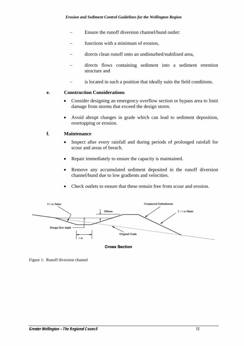
A non-erodible channel or bund for the conveyance of runoff constructed to a site specific cross section and grade design (see Figure 1).
b. Purpose To either protect work areas from upslope runoff (cleanwater diversion – see Figure 2), or to divert sediment laden water to an appropriate sediment retention structure.
c. Application
• To divert clean upslope water away from areas to be worked (cleanwater diversion).
• To divert sediment-laden runoff from disturbed areas into sediment treatment facilities.
• To keep sediment from leaving the site at or near the perimeter of the construction area.
• Keep permanent diversions in place until the disturbed area is stabilised.
• Stabilise runoff diversion channels/bunds (where necessary) before use.
• In either temporary or permanent situations
d. Design
• Design the runoff diversion channel to carry the flow from the 5% AEP period storm (plus freeboard).
• Restrict grades to no more than 2% unless armoured.
• Construct with a trapezoidal cross sectional shape with internal side slopes no steeper than 3:1 and external slopes no steeper than 2:1.
• Construct runoff diversion bunds with side slopes no steeper than 3:1.
• Survey all gradients on the site.
• Ensure earth embankments used to construct runoff diversion channels/bunds are adequately compacted.
• Flow velocities greater than 1m/s will cause the runoff diversion channel/bund to erode. Incorporate stabilisation measures (such as geotextile, vegetative stabilisation or rock check dams) to minimise erosion.
• Incorporate a stable erosion-proof outfall (such as a level spreader, see Section 4.4) in order to reduce water velocities and prevent scour at the outlet.
Erosion and Sediment Control Guidelines for the Wellington Region
Greater Wellington – The Regional Council 15
− Ensure the runoff diversion channel/bund outlet:
− functions with a minimum of erosion,
− directs clean runoff onto an undisturbed/stabilised area,
− directs flows containing sediment into a sediment retention structure and
− is located in such a position that ideally suits the field conditions.
e. Construction Considerations
• Consider designing an emergency overflow section or bypass area to limit damage from storms that exceed the design storm.
• Avoid abrupt changes in grade which can lead to sediment deposition, overtopping or erosion.
f. Maintenance
• Inspect after every rainfall and during periods of prolonged rainfall for scour and areas of breach.
• Repair immediately to ensure the capacity is maintained.
• Remove any accumulated sediment deposited in the runoff diversion channel/bund due to low gradients and velocities.
• Check outlets to ensure that these remain free from scour and erosion.
Figure 1: Runoff diversion channel

Erosion and Sediment Control Guidelines for the Wellington Region
16 Greater Wellington - The Regional Council
Figure 2: Clearwater runoff diversion bund
4.2 Contour Drain
Plate 3: Contour drain
a. Definition A temporary ridge or excavated channel, or combination of ridge and channel, constructed to convey water across sloping land on a minimal gradient (see Figure 3).
b. Purpose To periodically break overland flow across disturbed areas in order to limit slope length and thus the erosive power of runoff and to divert sediment-laden water to appropriate controls or stable outlets.

Erosion and Sediment Control Guidelines for the Wellington Region
Greater Wellington – The Regional Council 17
c. Application
• At intervals across disturbed areas to shorten overland flow distances.
• As temporary or daily controls.
• To split and direct flow from disturbed areas to runoff diversion channels/bunds.

Erosion and Sediment Control Guidelines for the Wellington Region
18 Greater Wellington - The Regional Council
d. Design
• Gradients of contour drains should be no greater than 2%.
• Keep drains short as practicable to minimise erosion (50m maximum length).
• The positioning of contour drains is determined by the necessity for stable outfalls, but in general the following spacing applies:
Table 1: Positioning of contour drains Slope of Site (%) Suggested Spacing of Contour
Drains (m) 5 50 10 40 15 30
e. Maintenance
• Install contour drains at the end of each day.
• Inspect contour drains after every rainfall and during periods of prolonged rainfall.
• Immediately carry out any maintenance that is required.
Figure 3: Contour drain

Erosion and Sediment Control Guidelines for the Wellington Region
Greater Wellington – The Regional Council 19
4.3 Rock Check Dam
Plate 4: Rock check dam
a. Definition Small temporary dam constructed across a channel (excluding perennial waterbodies), usually in series, to reduce flow velocity. It may also retain coarse sediment (see Figure 4).
b. Purpose To reduce the velocity of concentrated flows, thereby reducing erosion of the channel. Rock check dams will trap some sediment, but they are not designed as a sediment retention measure.
c. Application
• Do not use rock check dams in a perennial waterbodies.
• Short length temporary channels which are not suitable for non-erodible lining but still need some protection to reduce erosion.
• Permanent channels which cannot receive a permanent non-erodible lining for an extended period of time.
• Temporary or permanent channels which need protection during the establishment of a vegetative cover.

Erosion and Sediment Control Guidelines for the Wellington Region
20 Greater Wellington - The Regional Council
d. Design
• Catchment area should be less than 1 ha. Specifically designed rock check dams will be required in catchments greater than 1 ha.
• Direct all flows toward the centre of the rock check dam.
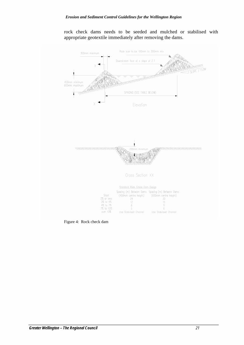
• Construct each rock check dam with a maximum centre height of 600mm. Build the sides 200mm higher than the centre to direct flows to the centre.
• Place a mix of 100mm to 300mm diameter washed rock so that it completely covers the width of the channel. In steeper catchments use larger sized rock (0.5m - 1.0m) on the downstream side of the rock check dam.
• Rock batter slopes are 2:1.
• Locate rock check dams so that the toe of the upstream dam is equal in height elevation to the crest of the downstream one (see Table 2). Ensure the toe of the upstream dam is never higher than the crest of the downstream dam.
• Make sure any sediment-laden runoff passes through sediment trapping device or devices before being discharged from the site.
• Do not use rock check dams as a primary sediment trapping facility.
Table: 2: Rock check dam design Slope (%) Spacing (m) Between Dams 450mm Centre Height 600mm Centre Height
<2 24 30 2 to 4 12 15 4 to 7 8 11 7 to 10 5 6 Over 10 Utilise Stabilised Channel
e. Maintenance
• Although this measure is not intended for sediment trapping, some sediment may accumulate behind rock check dams. Remove this sediment when it has accumulated up to 50% of the original height of the dam.
• When temporary channels are no longer required, remove rock check dams and fill in the channel.
• In permanent channels, remove rock check dams when a permanent lining can be installed.
• In the case of grass lined ditches, rock check dams may be removed when grass has matured sufficiently to protect the channel. The area beneath the
Erosion and Sediment Control Guidelines for the Wellington Region
Greater Wellington – The Regional Council 21
rock check dams needs to be seeded and mulched or stabilised with appropriate geotextile immediately after removing the dams.
Figure 4: Rock check dam

Erosion and Sediment Control Guidelines for the Wellington Region
22 Greater Wellington - The Regional Council
4.4 Level Spreader
Plate 5: Level spreader with forebay.
a. Definition A non-erosive outlet to disperse concentrated runoff uniformly across a slope (see Figure 5).
b. Purpose The level spreader provides a relatively low cost option, which can convert concentrated flow to sheet flow and release it uniformly over a stabilised area.
c. Application
• Where sediment free stormwater runoff can be released in a sheet flow over a stabilised slope without causing erosion.
• Where sediment-laden overland flow can be released in sheet flow across the inlet to a sediment retention pond.

Erosion and Sediment Control Guidelines for the Wellington Region
Greater Wellington – The Regional Council 23
• Where the area below the level spreader lip is uniform with a slope of 10% or less and/or is stable for the anticipated flow conditions.
• Where the runoff water will not re-concentrate after release and there will be no traffic over the level spreader.
d. Design
• Determine the capacity of the level spreader by estimating the peak flow from the 20 year storm event.
• Where possible, choose a site for the level spreader that has a natural contour that will allow for the rapid spreading of flows, - at the end of a knoll or ridge.
• Select the length, width and depth of the spreader from Table 3 below.
• Construct a 6m long transition section in the runoff diversion channel leading up to the level spreader so the width of the runoff diversion channel will smoothly meet the width of the level spreader to ensure uniform outflow. The level spreader trench tapers down to 1m at the end of the level spreader.
• Maintain a minimum inlet width of 3m.
• Make sure the grade of the level spreader is 0%.
• Construct the level spreader lip on undisturbed soil, incorporating a 50mm x 150mm board (spreader beam) levelled and positioned edge on as shown below. Particular care is required to ensure the level spreader outlet lip is completely level and is in stable undisturbed soil or is well armoured. Any depressions in the level spreader lip will re-concentrate flows, resulting in further erosion. An alternative is to armour the level spreader to a uniform height and zero grade over the length of the level spreader. Use geotextile and ensure the disturbed area is seeded and fertilised for vegetation establishment.
Table 3: Level spreader design criteria Design Flow
(m3/sec) Inlet Width
(m) Depth (mm)
End Width (m)
Length (m)
0 – 0.3 3 150 1 3 0.3 – 0.6 5 180 1 7 0.6 – 0.9 7 220 1 10
e. Maintenance
• Inspect level spreaders after every rainfall until vegetation is established and promptly undertake any necessary repairs. Make sure vegetation is in a healthy and vigorous condition.

Erosion and Sediment Control Guidelines for the Wellington Region
24 Greater Wellington - The Regional Council
Figure 5: Level spreader
Erosion and Sediment Control Guidelines for the Wellington Region
Greater Wellington – The Regional Council 25
4.5 Pipe Drop Structure / Flume
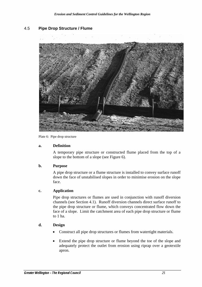
Plate 6: Pipe drop structure
a. Definition A temporary pipe structure or constructed flume placed from the top of a slope to the bottom of a slope (see Figure 6).
b. Purpose A pipe drop structure or a flume structure is installed to convey surface runoff down the face of unstabilised slopes in order to minimise erosion on the slope face.
c. Application Pipe drop structures or flumes are used in conjunction with runoff diversion channels (see Section 4.1). Runoff diversion channels direct surface runoff to the pipe drop structure or flume, which conveys concentrated flow down the face of a slope. Limit the catchment area of each pipe drop structure or flume to 1 ha.
d. Design
• Construct all pipe drop structures or flumes from watertight materials.
• Extend the pipe drop structure or flume beyond the toe of the slope and adequately protect the outlet from erosion using riprap over a geotextile apron.

Erosion and Sediment Control Guidelines for the Wellington Region
26 Greater Wellington - The Regional Council
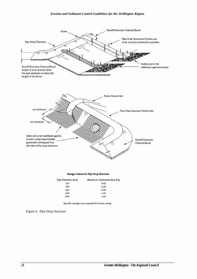
• At the pipe drop structure inlet, make sure the height of the runoff diversion channel is at least twice the pipe diameter or height of flume as measured from the invert (see Table 4).
• Install a flared entrance section of compacted earth. To minimise erosion, place impermeable geotextile fabric into the inlet extended a minimum of 1m in front of and to the side of the inlet and up the sides of the flared entrance. The geotextile should be keyed 150mm into the ground along all edges.
• When the catchment area is disturbed, ensure the pipe drop structure or flume discharges into a sediment retention pond or a stable conveyance system that leads to a pond. When the catchment area is stabilised, ensure the pipe drop structure or flume outlets onto a stabilised area at a non-erosive velocity. The point of discharge may be protected by rock rip rap.
• The pipe drop structure or flume should have a minimum slope of 3%.
Table 4: Design criteria for pipe drop structure Pipe Diameter (mm) Maximum Catchment Area (ha)
150 0.05 300 0.2 450 0.6 500 1.0 600 1.0
e. Construction Considerations for Pipe Drop Structures
• A common failure of pipe drop structures is caused by water saturating the soil and seeping along the pipe where it connects to the runoff diversion channel. Backfill around and under the pipe with stable material to achieve firm contact between the pipe and the soil at all points. Pipe material can consist of rigid pipe or flexible pipe as required. If flexible pipe is used, it is important that the material be pinned to the slope.
• Place pipe drop structures on undisturbed soil or well compacted fill. Immediately stabilise all disturbed areas following construction. Secure the pipe drop structure to the slope at least every 4m. Use at least two anchors equally spaced along the length of the pipe and all connections are watertight.
f. Construction Considerations for Flumes
• A common failure of flumes is outflanking of the flume entrance or scouring of the invert to the flume. This can be prevented by trenching an appropriate impervious geotextile or plastic liner at the entrance so all flows are channelled directly into the flume. Alternatively, a piped entrance can be installed.
• Flumes can be constructed from materials such as corrugated steel, construction ply, sawn timber or halved plastic piping.

Erosion and Sediment Control Guidelines for the Wellington Region
Greater Wellington – The Regional Council 27
• Construct the flume to ensure there are no leaks. For wooden or plywood flumes or flumes where leakage is likely, extend an impervious liner down the full length of the flume structure.
• Fasten the flume to the slope using waratahs or wooden stakes placed in pairs down the slope at 1m to 4m spacings, depending on the flume material used. Fasten the flume to the waratahs or stakes using wire or steel strapping.
• Place flumes on undisturbed soil or well compacted fill at locations as detailed in the site’s Erosion and Sediment Control Plan.
g. Maintenance
• Inspect the pipe drop structure/flume periodically and after each rainfall event.
• Immediately carry out any maintenance required. Keep the inlet open at all times.
Erosion and Sediment Control Guidelines for the Wellington Region
28 Greater Wellington - The Regional Council
Figure 6: Pipe Drop Structure

Erosion and Sediment Control Guidelines for the Wellington Region
Greater Wellington – The Regional Council 29
4.6 Benched Slope
Plate 7: Benched slope
a. Definition
• Modification of a slope by reverse sloping to divert runoff to an appropriate conveyance system (see Figure 7).
b. Purpose
• To limit the velocity and volume and hence the erosive power of water flowing down a slope and therefore minimising erosion of the slope face.
c. Application
• Benching is primarily used on long slopes and/or steep slopes where rilling may be expected as runoff flows down slope. Consider benching on all slopes. The spacing of the benched slopes and the specific conditions for which they apply depend on slope height and angle. The primary purpose is to minimise the concentration of runoff.
d. Design
• Divide the slope face as equally as possible to convey water from each bench to a stable outlet. Soil types, seeps and location of rock outcrops need to be taken into consideration when designing benched slopes.
• Make benched slopes a minimum of 2m wide for ease of maintenance (see Table 5).
• Design benched slopes with a reverse slope of 15% or flatter to the toe of the upper slope and with a minimum depth of 0.3m. Keep the gradient of

Erosion and Sediment Control Guidelines for the Wellington Region
30 Greater Wellington - The Regional Council
each bench to its outlet below 2%, unless design, stabilisation and calculations demonstrate that erosion is minimised.
• Keep the flow length along a benched slope to less than 250m unless design calculations can demonstrate that erosion is minimised.
Divert surface water from the face of all cut and/or fill slopes of benched slopes by the use of runoff diversion channels/bunds except where:
• The face of the slope is not subject to any concentrated flows of surface water such as from natural drainage, channels or other concentrated discharge points and;
• The face of the slope is protected by special erosion control materials including, but not limited to, approved vegetative stabilisation practices, rip-rap, or other approved stabilisation methods.
Provide subsurface drainage where necessary to intercept seepage that would otherwise adversely affect slope stability or create excessively wet site conditions. Check the requirements of the city or district council.
Do not construct benched slopes close to property lines where they could endanger adjoining properties without adequately protecting such properties against sedimentation, erosion, slippage, settlement, subsidence or other related damages. Check the requirements of the city or district council. Table 5: Benched slope design
Slope Angle (%) Vertical Height Between Benches (m)
50 10 33 15 25 20
e. Construction Considerations
• Compact all fills to reduce erosion, slippage, settlement and subsidence.
• Keep all benched slopes free of unconsolidated sediment during all phases of development
• Permanently stabilise all graded areas immediately on completion of grading.

Erosion and Sediment Control Guidelines for the Wellington Region
Greater Wellington – The Regional Council 31
Figure 7: Benched slope

Erosion and Sediment Control Guidelines for the Wellington Region
32 Greater Wellington - The Regional Council
4.7 Surface Roughening
Plate 8: Surface roughening
a. Definition
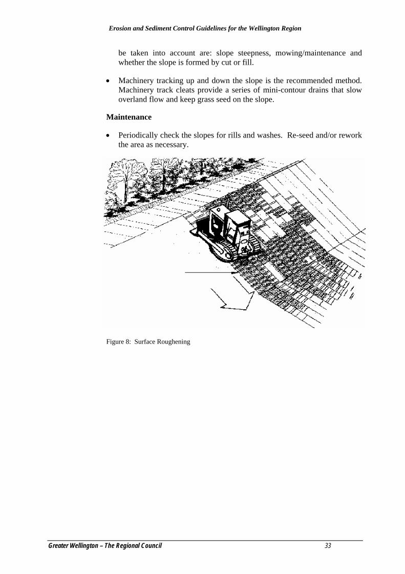
• Roughening a bare earth surface with horizontal grooves running across a slope or tracking with construction equipment (see Figure 8).
b. Purpose
• To aid in the establishment of vegetative cover from seed, to reduce runoff velocity, to increase infiltration, to reduce erosion and assist in sediment trapping.
c. Application
• Apply surface roughening on all construction sites requiring slope stabilisation with vegetation particularly slopes steeper than 25%.
d. Design Not Applicable.
e. Construction Considerations
• Surface roughening aids in establishment of vegetation, improves infiltration and decreases runoff velocity. Graded areas with smooth, hard surfaces may be initially attractive but such surfaces increase the potential for erosion. A rough, loose soil surface gives a mulching effect that protects fertiliser and seed.
• Various methods are available for surface roughening such as stair step grading, discing and forming grooves by machinery tracking. Factors to
Erosion and Sediment Control Guidelines for the Wellington Region
Greater Wellington – The Regional Council 33
be taken into account are: slope steepness, mowing/maintenance and whether the slope is formed by cut or fill.
• Machinery tracking up and down the slope is the recommended method. Machinery track cleats provide a series of mini-contour drains that slow overland flow and keep grass seed on the slope.
Maintenance
• Periodically check the slopes for rills and washes. Re-seed and/or rework the area as necessary.
Figure 8: Surface Roughening
Erosion and Sediment Control Guidelines for the Wellington Region
34 Greater Wellington - The Regional Council
4.8 Stabilised Construction Entrance
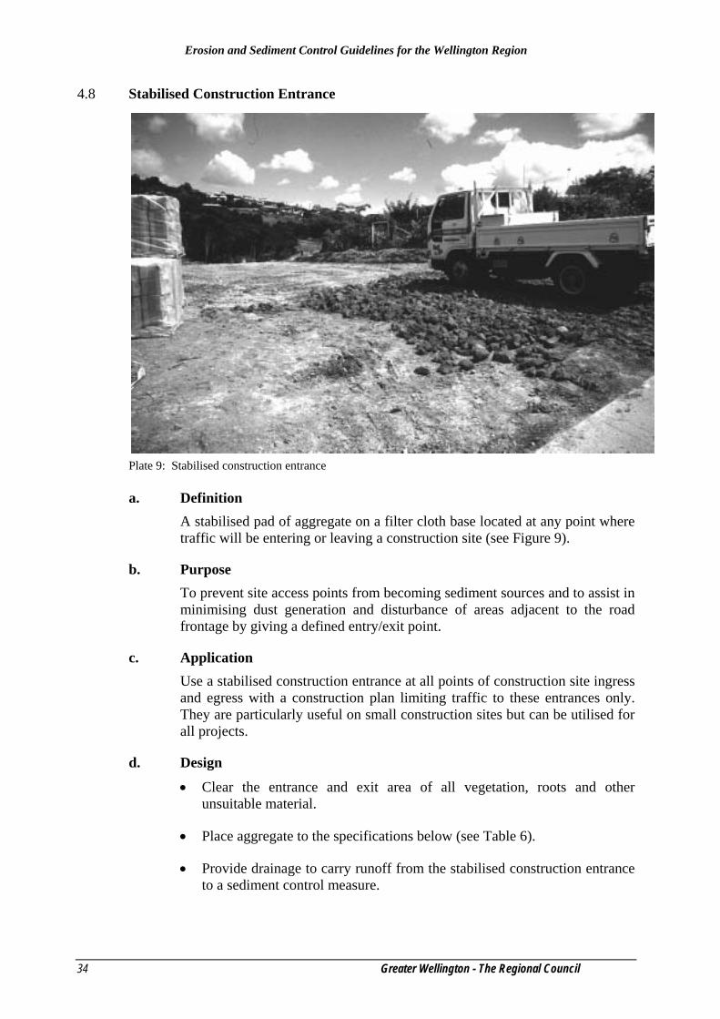
Plate 9: Stabilised construction entrance
a. Definition A stabilised pad of aggregate on a filter cloth base located at any point where traffic will be entering or leaving a construction site (see Figure 9).
b. Purpose To prevent site access points from becoming sediment sources and to assist in minimising dust generation and disturbance of areas adjacent to the road frontage by giving a defined entry/exit point.
c. Application Use a stabilised construction entrance at all points of construction site ingress and egress with a construction plan limiting traffic to these entrances only. They are particularly useful on small construction sites but can be utilised for all projects.
d. Design
• Clear the entrance and exit area of all vegetation, roots and other unsuitable material.
• Place aggregate to the specifications below (see Table 6).
• Provide drainage to carry runoff from the stabilised construction entrance to a sediment control measure.
Erosion and Sediment Control Guidelines for the Wellington Region
Greater Wellington – The Regional Council 35
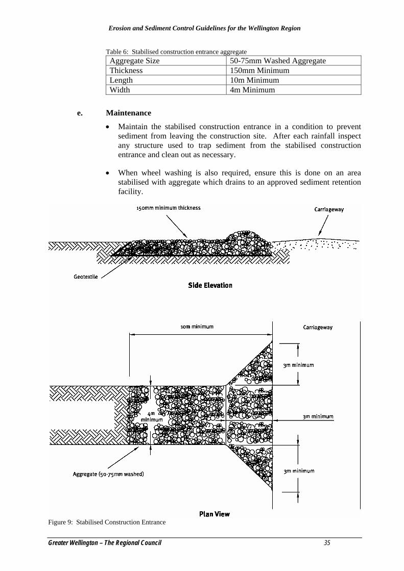
Table 6: Stabilised construction entrance aggregate Aggregate Size 50-75mm Washed Aggregate Thickness 150mm Minimum Length 10m Minimum Width 4m Minimum
e. Maintenance
• Maintain the stabilised construction entrance in a condition to prevent sediment from leaving the construction site. After each rainfall inspect any structure used to trap sediment from the stabilised construction entrance and clean out as necessary.
• When wheel washing is also required, ensure this is done on an area stabilised with aggregate which drains to an approved sediment retention facility.
Figure 9: Stabilised Construction Entrance

Erosion and Sediment Control Guidelines for the Wellington Region
36 Greater Wellington - The Regional Council
4.9 Geosynthetic Erosion Control Systems (GECS) a. Definition
The protection of channels and erodible slopes utilising artificial erosion control material such as geosynthetic matting, geotextiles or erosion matting (see Figures 10 and 11).
b. Purpose To immediately reduce the erosion potential of disturbed areas and/or to reduce or eliminate erosion on critical sites during the period necessary to establish protective vegetation. Some forms of artificial protection may assist in the establishment of protective vegetation.
c. Application
• On short steep slopes.
• On areas that have highly erodible soils.
• In situations where tensile and shear strength characteristics of conventional mulches limit their effectiveness in high runoff velocities.
• In channels (both perennial and ephemeral) where the design flow produces tractive shear forces greater than the in-situ soil can withstand.
• In areas where there is not enough room to install adequate sediment controls.
• In critical erosion prone areas such as sediment retention pond outlet and inlet points.
• In areas that may be slow to establish an adequate permanent vegetative cover.
• In areas where the downstream environment is of high value and rapid stabilisation is required.
d. Design There are two categories of GECS; temporary degradable and permanent non-degradable.
Temporary Degradable GECS
These are used to prevent loss of seedbed and to promote vegetation establishment where vegetation alone will be sufficient for site protection. The common temporary GECS is the erosion control blanket. This is an open weave mesh/matting and organic erosion control netting (fibre mats factory bonded to synthetic netting).
Permanent Non-Degradable GECS
These are used to extend the erosion control limits of vegetation, soil, rock or other materials. Common permanent GECS are three dimensional erosion

Erosion and Sediment Control Guidelines for the Wellington Region
Greater Wellington – The Regional Council 37
control and revegetation mats, geocellular confinement systems, reno mattresses and gabions.
The selection of an appropriate GECS is a complex balancing act of the relative importance of the following requirements:
• Endurance: durability, degree of resistance to deformation over time, ultraviolet radiation and chemicals, whether natural or as pollutants.
• Physical: thickness, weight, specific gravity and degree of light penetration. Generally a thicker heavier material will provide better protection.
• Hydraulic: ability of the system to resist tractive shear strength and protect against channel erosion, erosion of underlying soils or slope erosion from rainfall impact.
• Mechanical: deformation and strength behaviour. Tensile strength and elongation, stiffness (how well it will conform to the subgrade) and how well it will resist tractive shear forces.
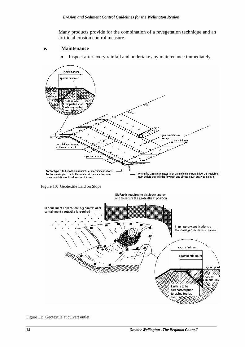
When a geotextile is to be used for temporary channel or spillway protection consider combining a high strength, low permeability cloth over a soft pliable needle punch cloth pinned to ensure the cloth is in contact with the entire soil surface (see Figures 10 & 11). Trench and pin all flow entry points such that the upslope geotextile edge overlaps the downslope geotextile mat (which has been toed in on the upslope end).
In high risk areas such as spillways and diversions, pin geotextiles down on a 0.5m grid or in accordance with the manufacturers’ specifications, whichever provides the greatest number of contact points.
There are a large number of products available for all situations and depending on the degree of protection required, a product or combination of products will be available that will suit the situation. It is important that the product utilised is designed for the intended use and installed and maintained according to its specifications. Decision analysis techniques ranking the various GECS available should be used based on the following categories:
• Sediment yield (generally ranked highest)
• Stability under flow
• Vegetation enhancement
• Durability
• Cost
When installing GECS within a channel, it is important that the design velocity of the product is considered.
Erosion and Sediment Control Guidelines for the Wellington Region
38 Greater Wellington - The Regional Council
Many products provide for the combination of a revegetation technique and an artificial erosion control measure.
e. Maintenance
• Inspect after every rainfall and undertake any maintenance immediately.
Figure 10: Geotextile Laid on Slope
Figure 11: Geotextile at culvert outlet

Erosion and Sediment Control Guidelines for the Wellington Region
Greater Wellington – The Regional Council 39
4.10 Revegetation Techniques
4.10.1 Top Soiling a. Definition
The placement of topsoil over a prepared subsoil prior to the establishment of vegetation.
b. Purpose To provide a suitable soil medium for vegetative growth while providing some limited short term erosion control capability.
c. Application Topsoil provides the major zone for root development and biological activities as well as having greater available water holding capacity than clay subsoils.
• Top soiling is recommended for sites where:
• The texture and/or the organic component of the exposed subsoil or parent material can not produce adequate vegetative growth.
• The soil material is so shallow that the rooting zone is not deep enough to support plants or furnish continuing supplies of moisture and plant nutrients.
• High quality turf and landscape plantings are to be established.
Top soiling combined with vegetation establishment is not seen as an erosion control measure. Top soiling is usually limited to sites with an average slope of less than 5% with contour drains for periods of less than two weeks. Top soiling alone will not provide sufficient erosion protection to allow sediment control measures to be removed. When staging within an earthworks operation, top soiling as a treatment is not acceptable and other means of stabilisation will be required.
d. Design Not Applicable.
e. Considerations
• When site shaping work has been completed, evenly spread a minimum of 100mm of topsoil before re-vegetating. On steeper sites (over 25% slope) scarify the subsoils to a depth of a least 100mm to ensure bonding between topsoil and subsoil. Operators should incorporate surface roughening (see Section 4.7) into all top soiling operations.
• Topsoil has a beneficial effect in light rain because it can hold more moisture than the underlying clay material. During heavy rain topsoil will become saturated and rill erosion and slumping may result. For this reason it is important to establish a full vegetative cover as soon as
Erosion and Sediment Control Guidelines for the Wellington Region
40 Greater Wellington - The Regional Council
possible and retain all sediment retention facilities on the site until a vegetative cover is fully established.
f. Maintenance
• Check the condition of the topsoil on a regular basis and re-grade and/or replace where necessary to maintain the 100mm minimum depth of topsoil and surface roughening.
4.10.2 Temporary and Permanent Seeding a. Definition
The planting and establishment of quick growing and/or perennial vegetation to provide temporary and/or permanent stabilisation on exposed areas.
b. Purpose Temporary seeding is designed to stabilise the soil and to protect disturbed areas until permanent vegetation or other erosion control measures can be established. Temporary seeding may be used where an area is not yet up to final grade but requires stabilisation before commencement of further earthworks. Permanent seeding is designed to permanently stabilise soil on disturbed areas to reduce sediment runoff to off-site areas.
c. Application Temporary seeding is used on any cleared or unvegetated areas which are subject to erosion and will not be disturbed for a period of 14 days or more. Temporary stabilisation is normally practised where vegetative cover is required for less than one year. In some circumstances straw mulching may be used as an alternative.
Permanent seeding applies to any site where establishment of permanent vegetation is used to protect bare earth. It may also be used on rough graded areas that will not be brought to final grade for a year or more.
d. Design Not Applicable.
e. Considerations
• Before seeding install all required erosion and sediment control practices such as diversion channels and sediment retention structures. Grade the site to allow the use of conventional equipment for soil preparation, seeding and maintenance.
• Prepare a good seed bed for successful establishment of vegetation. Take care to ensure that the seed bed is free of large clods, rocks and other unsuitable material. Apply topsoil at a minimum depth of 100mm to allow for a loose and friable soil surface.
• Apply fertiliser as outlined in the Code of Practice for Fertiliser Use (1998).
Erosion and Sediment Control Guidelines for the Wellington Region
Greater Wellington – The Regional Council 41
• For large sites or unusual site conditions it is advisable to have soil fertility tests done.
• Apply the seed uniformly and sow at the recommended rate. Broadcast seed must be covered by raking and lightly tamped into place. Hydroseeding can be utilised in accordance with Section 4.10.3 of these Guidelines.
• When working on steep sites (greater than 25%) or during the winter period (between April 30 and October 1), mulching may be applied in accordance with Section 4.10.4 of these Guidelines immediately following seeding.
• Adequate moisture is essential for seed germination and plant growth. Irrigation is important for establishing vegetation during dry or hot weather conditions or on adverse site conditions. Irrigation must be controlled to minimise runoff and subsequent erosion.
f. Maintenance
• Re-seed where germination is unsatisfactory or where erosion has occurred. In the event of unsatisfactory germination the area may require mulch (see Section 4.10.4).
• Depending on site conditions it may be necessary to irrigate, fertilise, oversow or re-establish plantings in order to provide vegetation for adequate erosion control.
• Protect all revegetated areas from traffic flows and other activities such as the installation of drainage lines and utility services.
4.10.3 Hydroseeding a. Definition
The application of seed, fertiliser and a paper or wood pulp with water in the form of a slurry which is sprayed over the area to be revegetated.
b. Purpose To establish vegetation quickly while providing a degree of instant protection from rain drop impact.
c. Application
• This measure applies to any site where vegetation establishment is important for the protection of bare earth surfaces such as:
• Critical areas on the site prone to erosion such as steep slopes and sediment retention pond batters.
• Critical areas on the site that cannot be stabilised by conventional sowing methods.
Erosion and Sediment Control Guidelines for the Wellington Region
42 Greater Wellington - The Regional Council
• Around waterbodies or runoff diversion channels where rapid establishment of a protective vegetative cover is required before introducing flows.
d. Design Not Applicable.
e. Considerations
• The seed adheres to the pulp which improves the microclimate for germination and establishment. This method allows vegetation to be established on difficult sites and can extend into cooler winter months provided it is utilised with mulching (see Section 4.10.4).
• Before hydroseeding, install any needed erosion and sediment control practices such as runoff diversion channels. Scarify any steep or smooth clay surfaces to improve retention of the hydroseed slurry.
• Hydroseeding requires moisture for germination. Because hydroseeding is often used for difficult sites the timing of the application to get favourable growing conditions is an important factor.
f. Maintenance
• Heavy rainfall can wash hydroseed from smooth clay surfaces and overland flowpaths. Where vegetation establishment is unsatisfactory the area will require hydroseeding again.
• Protect all revegetated areas from traffic flows and other activities such as the installation of drainage lines and utility services.

Erosion and Sediment Control Guidelines for the Wellington Region
Greater Wellington – The Regional Council 43
4.10.4 Mulching
Plate 10: Mulching spreader a. Definition
The application of a protective layer of straw or other suitable material to the soil surface.
b. Purpose To protect the soil surface from the erosive forces of raindrop impact and overland flow. Mulching assists in soil moisture conservation, reduces runoff and erosion, controls weeds, prevents soil crusting and promotes the establishment of desirable vegetation.
c. Application This practice applies to any site where vegetation establishment is important for the protection of bare earth surfaces. Mulching can be used in conjunction with seeding to establish vegetation, or to provide temporary protection of the soil surface.
Mulching can be applied at any time during the year. It is commonly used during the winter months (April 30 to 1 October) to provide immediate stabilisation, as conventional sowing of grass is ineffective due to slow seed germination.
Erosion and Sediment Control Guidelines for the Wellington Region
44 Greater Wellington - The Regional Council
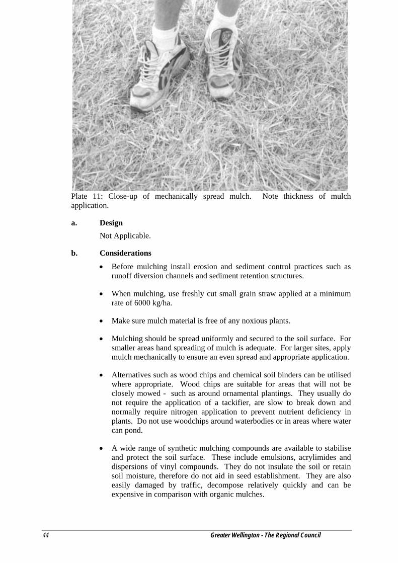
Plate 11: Close-up of mechanically spread mulch. Note thickness of mulch application.
a. Design Not Applicable.
b. Considerations
• Before mulching install erosion and sediment control practices such as runoff diversion channels and sediment retention structures.
• When mulching, use freshly cut small grain straw applied at a minimum rate of 6000 kg/ha.
• Make sure mulch material is free of any noxious plants.
• Mulching should be spread uniformly and secured to the soil surface. For smaller areas hand spreading of mulch is adequate. For larger sites, apply mulch mechanically to ensure an even spread and appropriate application.
• Alternatives such as wood chips and chemical soil binders can be utilised where appropriate. Wood chips are suitable for areas that will not be closely mowed - such as around ornamental plantings. They usually do not require the application of a tackifier, are slow to break down and normally require nitrogen application to prevent nutrient deficiency in plants. Do not use woodchips around waterbodies or in areas where water can pond.
• A wide range of synthetic mulching compounds are available to stabilise and protect the soil surface. These include emulsions, acrylimides and dispersions of vinyl compounds. They do not insulate the soil or retain soil moisture, therefore do not aid in seed establishment. They are also easily damaged by traffic, decompose relatively quickly and can be expensive in comparison with organic mulches.

Erosion and Sediment Control Guidelines for the Wellington Region
Greater Wellington – The Regional Council 45
• Rovings are fibres that are teased out from spools of yarn by compressed air and woven onto the surface of the land. They are stabilised with a tackifier.
• Anchor mulch to avoid loss by wind or water. Mulch is ‘settled’ in place by the first rainfall but may be retained by crimping into the soil with discs or spraying with a tackifier. When using some chemical tackifiers, take care to avoid adverse offsite effects, such as contamination of nearby waterbodies.
• These alternatives may be acceptable in certain circumstances but should be discussed with the Consent staff from Greater Wellington – The Regional Council prior to application.
Plate 12: Turf matting
4.10.5 Turfing
a. Definition The establishment and permanent stabilisation of disturbed areas by laying a continuous cover of grass turf.
b. Purpose To provide immediate vegetative cover to stabilise soil on disturbed areas such as:
• Critical erosion prone areas.
• Critical areas that cannot be stabilised by conventional sowing methods.
• Runoff diversion channels and other areas of concentrated flow where velocities will not exceed the specifications for a grass lining.

Erosion and Sediment Control Guidelines for the Wellington Region
46 Greater Wellington - The Regional Council
c. Application Turfing is the preferred methodology for disturbed areas that must be immediately stabilised. It is particularly useful for:
• Waterbodies and channels carrying intermittent flow.
• Areas around drop inlets.
• Residential or commercial lawns to allow prompt use and for aesthetic reasons.
• Steep areas.
d. Design Not applicable.
e. Considerations
• Before turfing, prepare the site to ensure successful establishment of vegetation. This preparation should include applying fertiliser as per the Code of Practice for Fertiliser Use (1998), uniformly grading the area, clearing all debris, removing stones and clods and scarifying hard packed surfaces.
• During periods of high temperatures, lightly irrigate soil immediately before laying turf.
• Lay the first row of turf in a straight line with subsequent rows placed parallel to and tightly wedged against each other. Stagger lateral joints in a brick like pattern. Do not stretch or overlap turf and make sure all joints are butted tight in order to prevent voids, which can cause drying of the grass roots.
• On sloping areas or channels where erosion may be a problem, lay turf downslope with the ends of the turf overlapped such that the upslope turf overlaps the downslope turf by at least 100mm. It may be necessary to secure the turf with pegs or staples. Ensure the turf at the top of the slope is appropriately trenched to prevent runoff moving underneath.
• As turfing is completed in one area, roll or tamp the entire area to ensure solid contact of the grass roots with the soil surface. After rolling, immediately water the turf until the underside of the new turf and soil surface below the turf are thoroughly wet.
• For areas of high erosion potential, such as steep slopes or concentrated overland flow paths, turf reinforced with geosynthetic matting should be considered.
f. Maintenance
• Water daily during the first week of laying unless there is adequate rainfall. Do not mow the area until the turf is firmly rooted. Apply

Erosion and Sediment Control Guidelines for the Wellington Region
Greater Wellington – The Regional Council 47
fertiliser according to the Code of Practice for Fertiliser Use (1998) for ongoing successful establishment.

Erosion and Sediment Control Guidelines for the Wellington Region
Greater Wellington – The Regional Council 49
4. Sediment control measures This section outlines minimum criteria for the design, construction and implementation of a range of sediment control measures commonly used on earthworks sites and other land disturbing activities. These measures form one aspect of sediment control on any site and should always be used in conjunction with the principles outlined in Section 3.
The criteria outlined are the minimum standard for each measure. Each land disturbing activity must be assessed on an individual basis and in many cases higher standards may be required.
For each measure, these Guidelines outline:
a. Definition b. Purpose c. Application d. Design e. Construction Considerations f. Maintenance
Erosion and Sediment Control Guidelines for the Wellington Region
50 Greater Wellington - The Regional Council
5.1 Sediment Retention Pond
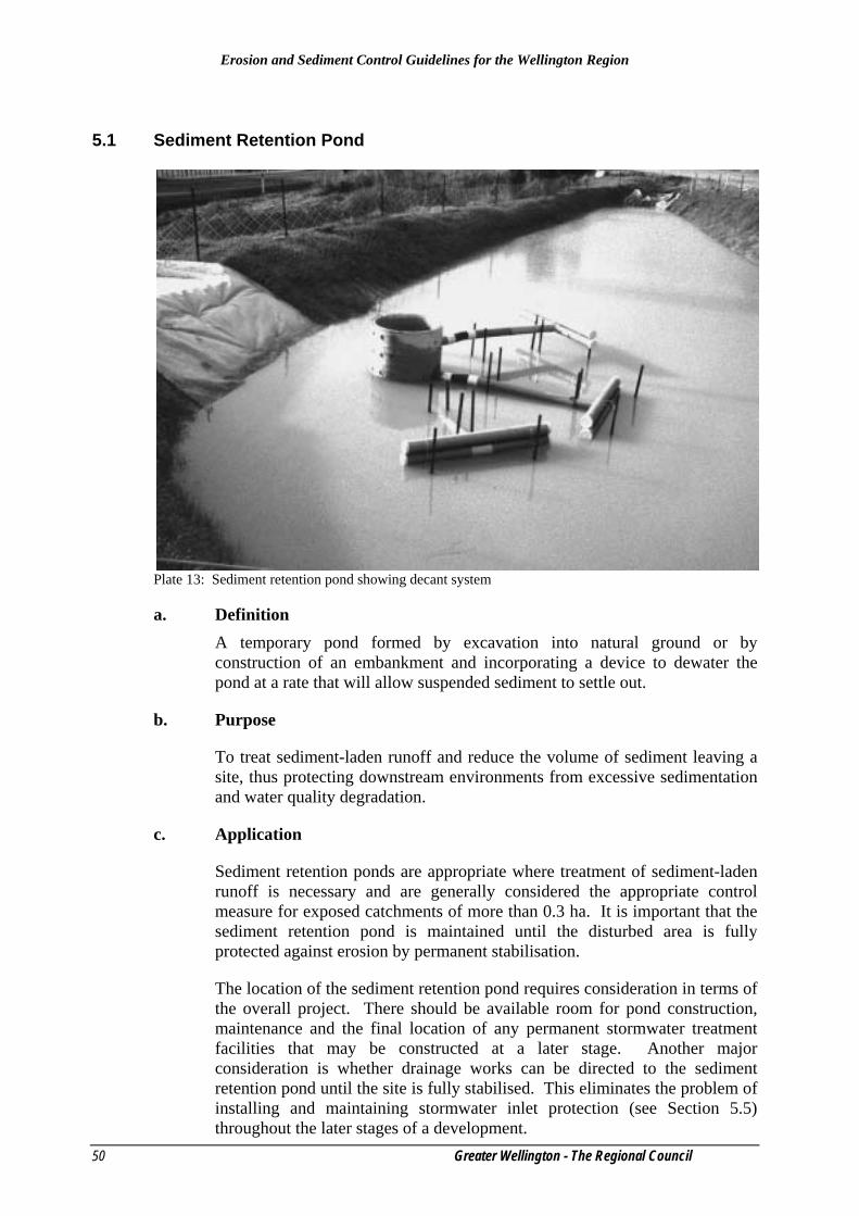
Plate 13: Sediment retention pond showing decant system a. Definition
A temporary pond formed by excavation into natural ground or by construction of an embankment and incorporating a device to dewater the pond at a rate that will allow suspended sediment to settle out.
b. Purpose
To treat sediment-laden runoff and reduce the volume of sediment leaving a site, thus protecting downstream environments from excessive sedimentation and water quality degradation.
c. Application
Sediment retention ponds are appropriate where treatment of sediment-laden runoff is necessary and are generally considered the appropriate control measure for exposed catchments of more than 0.3 ha. It is important that the sediment retention pond is maintained until the disturbed area is fully protected against erosion by permanent stabilisation.
The location of the sediment retention pond requires consideration in terms of the overall project. There should be available room for pond construction, maintenance and the final location of any permanent stormwater treatment facilities that may be constructed at a later stage. Another major consideration is whether drainage works can be directed to the sediment retention pond until the site is fully stabilised. This eliminates the problem of installing and maintaining stormwater inlet protection (see Section 5.5) throughout the later stages of a development.

Erosion and Sediment Control Guidelines for the Wellington Region
Greater Wellington – The Regional Council 51
The general approach is to create an impoundment of sufficient volume to capture a significant proportion of a predicted runoff event and to provide quiescent (stilling) conditions, which promote the settling of suspended sediment (see Figure 12). The sediment retention pond design is such that very large runoff events will receive at least partial treatment and smaller events will receive a high level of treatment. To achieve this, energy of inlet water needs to be low to minimise re-suspension of sediments and the decant rate of the outlet also needs to be low to minimise water currents forming, - to allow sufficient detention time for suspended sediment to settle out. Specific design criteria are discussed below: • Generally use sediment retention ponds for bare areas of bulk earthworks
of 0.3ha or greater.
• Restrict catchment areas to less than 3 ha per sediment retention pond. This limits the length of overland flowpaths and reduces maintenance problems.
• Locate sediment retention ponds to provide a convenient collection point for sediment-laden flows from the catchment area. This will require strategic use of cut-offs, runoff diversion channels and contour drains.
• Locate sediment retention ponds to allow access for removing sediment from the pond.
• Wherever possible locate sediment retention ponds to allow the spillway to discharge over undisturbed, well-vegetated ground.
• Keep the sediment retention pond life to less than two years. If a longer term is required then further measures to ensure stability and effectiveness are likely to be required.
• Do not locate sediment retention ponds within waterbodies.
• Embankment and spillway stability are generally the weak point in sediment retention pond construction. Correct compaction, particularly around emergency spillway discharge pipes and antiseep collars will keep the system robust.
Erosion and Sediment Control Guidelines for the Wellington Region
52 Greater Wellington - The Regional Council
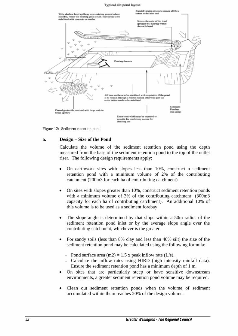
Figure 12: Sediment retention pond
a. Design – Size of the Pond Calculate the volume of the sediment retention pond using the depth measured from the base of the sediment retention pond to the top of the outlet riser. The following design requirements apply:
• On earthwork sites with slopes less than 10%, construct a sediment retention pond with a minimum volume of 2% of the contributing catchment (200m3 for each ha of contributing catchment).
• On sites with slopes greater than 10%, construct sediment retention ponds with a minimum volume of 3% of the contributing catchment (300m3 capacity for each ha of contributing catchment). An additional 10% of this volume is to be used as a sediment forebay.
• The slope angle is determined by that slope within a 50m radius of the sediment retention pond inlet or by the average slope angle over the contributing catchment, whichever is the greater.
• For sandy soils (less than 8% clay and less than 40% silt) the size of the sediment retention pond may be calculated using the following formula:
− Pond surface area (m2) = 1.5 x peak inflow rate (L/s). − Calculate the inflow rates using HIRD (high intensity rainfall data).
Ensure the sediment retention pond has a minimum depth of 1 m. • On sites that are particularly steep or have sensitive downstream
environments, a greater sediment retention pond volume may be required.
• Clean out sediment retention ponds when the volume of sediment accumulated within them reaches 20% of the design volume.
Erosion and Sediment Control Guidelines for the Wellington Region
Greater Wellington – The Regional Council 53
• Clearly show the sediment retention pond dimensions necessary to obtain the required volume, as detailed above, on the site’s Erosion and Sediment Control Plan(s).
e. Design – Dead Storage (Permanent Storage)
• Dead storage is the component of impoundment volume that does not decant and remains in the sediment retention pond. It is important for dissipating the energy of inflows.
• Ensure dead storage is 30% of the total sediment retention pond storage by positioning the lowest decant 0.4m–0.8m above the invert of the sediment retention pond.
• The decant design detailed in these Guidelines (see Figure 13) allows the lower decant arm to be raised as sediment deposition increases, thereby maintaining the percentage volume of dead storage.
f. Design – Live Storage (Decant Storage)
• Live storage is the volume between the lowest decant outlet level and the crest of the sediment retention pond primary spillway.
• Ensure that the live storage volume capacity is 70% of the total sediment retention pond storage.
• The decant design detailed in these Guidelines (see Figure 13) allows the decant system to be raised as sediment deposition increases, thereby maintaining the percentage volume of live storage.
g. Design – Decanting / Outlet Dewatering Device
• Dewater the sediment retention pond so as to remove the relatively clean water without removing any of the settled sediment and without removing any appreciable quantities of floating debris.
• The use of a floating T-bar dewatering device, which allows for the decanting of the cleaner surface water from the top of the water column, is preferred. Substantiated performance design will need to be submitted for decant systems other than the floating T-bar dewatering device.
• The recommended decant rate from a sediment retention pond is 2 L/s/ha of contributing catchment. This rate ensures that appropriate detention times are achieved.
• A standard T-bar design is detailed in Figure 13 for various sized catchments. This design has evolved through a number of trials the latest of which sought to find a decant that is less prone to blockage due to mulch or floating topsoil.
• To achieve a decant rate of 2 L/s per decant, the lower end of the decant is capped and a 28mm diameter hole is drilled in the centre of the cap. Slots
Erosion and Sediment Control Guidelines for the Wellington Region
54 Greater Wellington - The Regional Council
at 10mm centres using a 4mm wide cut-off blade are made along the full length of the decant. These slots extend a third of the way into the pipe.
• Single T-bar decants must be able to operate through the full live storage depth of the sediment retention pond.
• If two decant systems are required, ensure the lower T-bar decant operates through the full live storage depth of the sediment retention pond. The upper T-bar decant is to operate through the upper 50% of the live storage depth of the sediment retention pond only.
• Ensure that the T-bar decant float is securely fastened with steel strapping directly on top of the decant arm and weight it to keep the decant arm submerged just below the surface through all stages of the decant cycle. This will also minimise the potential for blockage of the decant slots by floating debris. The most successful method found to date is to weight the decant arm by strapping a 1.8m long waratah between the float and the decant (approximately 4kg of weight).
• Position the T-bar decant at the correct height by supporting the decant arm between waratahs as detailed in Figure 13.
• Lay the discharge pipe at a 1–5% gradient, compact the fill material around it using a machine compactor and incorporate anti-seep collars around the pipe to increase the seepage length along the pipe as required if the clay content is low.
• Use a flexible thick rubber (such as plumb quik) coupling to provide a connection between the decant arm and the primary spillway or discharge pipe. To provide sufficient flexibility (such as is required for the lower decant arm) install two couplings. Fasten the flexible coupling using strap clamps and glue.
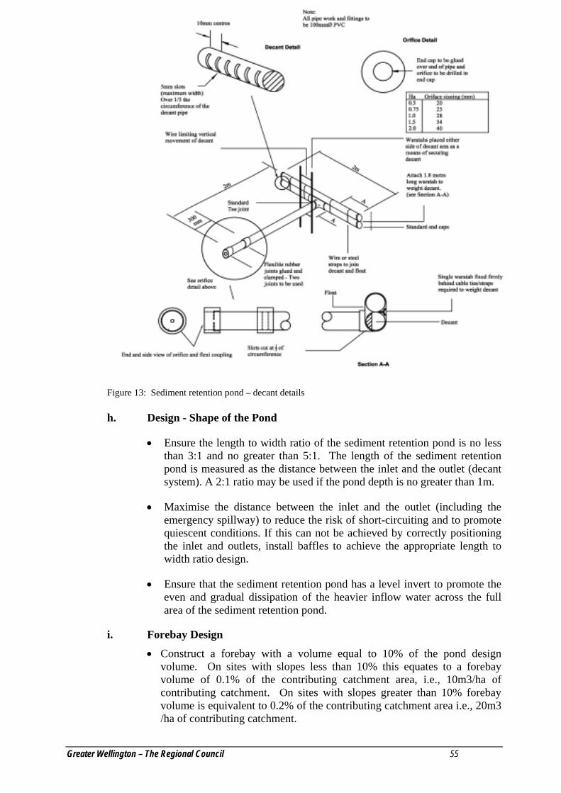
Erosion and Sediment Control Guidelines for the Wellington Region
Greater Wellington – The Regional Council 55
Figure 13: Sediment retention pond – decant details
h. Design - Shape of the Pond
• Ensure the length to width ratio of the sediment retention pond is no less than 3:1 and no greater than 5:1. The length of the sediment retention pond is measured as the distance between the inlet and the outlet (decant system). A 2:1 ratio may be used if the pond depth is no greater than 1m.
• Maximise the distance between the inlet and the outlet (including the emergency spillway) to reduce the risk of short-circuiting and to promote quiescent conditions. If this can not be achieved by correctly positioning the inlet and outlets, install baffles to achieve the appropriate length to width ratio design.
• Ensure that the sediment retention pond has a level invert to promote the even and gradual dissipation of the heavier inflow water across the full area of the sediment retention pond.
i. Forebay Design
• Construct a forebay with a volume equal to 10% of the pond design volume. On sites with slopes less than 10% this equates to a forebay volume of 0.1% of the contributing catchment area, i.e., 10m3/ha of contributing catchment. On sites with slopes greater than 10% forebay volume is equivalent to 0.2% of the contributing catchment area i.e., 20m3 /ha of contributing catchment.

Erosion and Sediment Control Guidelines for the Wellington Region
56 Greater Wellington - The Regional Council
• The forebay is to extend the full width of the main pond and is to be 0.5 to 1 m deep.
• Inlets to the forebay must be stabilised.
• Access to the forebay is to be maintained at all times to allow easy and frequent removal of accumulated sediments by an excavator. Sediment should be removed after every large storm event.
j. Design - Pond Level Spreader
• Incorporate a pond level spreader between the forebay and the main pond to spread inflow velocities, thereby allowing rapid dissipation of inflow energies. Combine the pond level spreader with a well-compacted and smoothed inlet batter (no steeper than a 3:1 gradient) stabilised over its entire area. The essential design feature is to ensure the pond level spreader is completely level, non-erodible and spans the full width of the sediment retention pond.
• To ensure even inflows, install a trenched and pegged 180mm x 50mm timber weir or similar across the full width of the inlet. Bund the edges with compacted earth to prevent outflanking. This timber weir is generally haunched using site concrete which also serves to toe in the geotextile protection which will be required.
k. Design – Baffles
• Incorporate baffles in the sediment retention pond design where the recommended pond shape cannot be achieved. Extend baffles the full depth of the sediment retention pond and place them to maximise dissipation of flow energy.
• Generally, baffles are in the form of a wing to direct inflows away from the outlet and maximise the stilling zone. A series of compartments within the pond can be used to achieve this, although care must be taken to avoid creating in-pond currents and re-suspension of light particles.
• Baffles may be constructed from various materials ranging from solid shutter boards to braced geotextile curtains.
l. Design - Depth of Pond
• Sediment retention pond depths may range from 1-2m deep, but no deeper than 2m. Deeper ponds are more likely to cause short-circuiting problems during larger storm events and require specifically designed floating decant systems.
• The decant design in these Guidelines operates through a maximum live storage range of 1.5m.

Erosion and Sediment Control Guidelines for the Wellington Region
Greater Wellington – The Regional Council 57
m. Design – Embankment
• Before building a sediment retention pond, install sediment controls such as silt fences below the construction area and maintain them to a functional standard until the sediment retention pond batters are fully stabilised.
• Thoroughly compact the sediment retention pond embankment with material laid in 150mm layers and compacted to engineering standards.
• Where possible, install the discharge pipes through the embankment as the embankment is being constructed.
• Fully stabilise the external batter face by vegetative or other means immediately after construction. Use with vegetation if the sediment retention pond is to remain in place over winter.
n. Design - Primary Spillway
• For catchments greater than 1.5 ha the sediment retention pond requires a primary piped spillway. (see Figures 14 and 15).
• For catchments up to 1.5 ha, decant flows can be piped using the same diameter pipe as the decant system (100mm PVC smooth bore) directly through the sediment retention pond wall to discharge beyond the toe of the sediment retention pond wall.
• For contributing catchments between 1.5 ha and 3 ha use a manhole riser spillway pipe diameter of 300mm.
• If the sediment retention pond is to operate over the winter and the contributing catchment is fully stabilised, disconnect the T-bar decant to reduce the frequency of emergency spillway activation and consequent erosion.
• Where a primary spillway upstand riser is used, place the top of the riser a minimum 600mm lower than the top of the sediment retention pond embankment and a minimum 300mm lower than the emergency spillway crest. Ensure the riser and the discharge pipe connections are all completely watertight.
o. Design - Emergency Spillway
• An emergency spillway is essential for all sediment retention ponds. Emergency spillways must be capable of accommodating the 1% AEP event without eroding. The emergency spillway crest and outer batter requires a high standard of stabilisation with well compacted fill material.
• Construct the emergency spillway as a stabilised trapezoidal cross section with a minimum bottom width of 4 m for catchments up to 1.5 ha or 6m for catchments up to 3 ha. The trapezoidal cross sections are to be continued down the outside batter to avoid flows outflanking the geotextile.

Erosion and Sediment Control Guidelines for the Wellington Region
58 Greater Wellington - The Regional Council
• When utilising geotextile for emergency spillway stabilisation purposes, the batter face must be smooth and all voids filled.
• If geotextile is used, a soft needle-punch geotextile is laid first and then covered with a strong woven low permeability geotextile. Ensure the geotextile is pinned at 0-5m centres over the full area of the emergency spillway.
p. Pond Maintenance and Disposal of Sediment
• Clean out sediment retention ponds before the volume of accumulated sediment reaches 20% of the total sediment retention pond volume. To assist in gauging sediment loads, clearly mark the 50% volume height on the decant riser.
• The Erosion and Sediment Control Plan should identify disposal locations for the sediment removed from the sediment retention pond. Deposit the sediment in a location where it will not be able to re-enter waterbodies. Stabilise all disposal sites as required and approved in the site’s Erosion and Sediment Control Plan.
q. Safety
• Sediment retention ponds are attractive to children and can be dangerous if not appropriately fenced and if safety rules are not followed. Low gradient pond batters provide an additional safety measure. Check the safety requirements of the City or District Council and the Occupational Safety and Health branch of the Department of Labour.
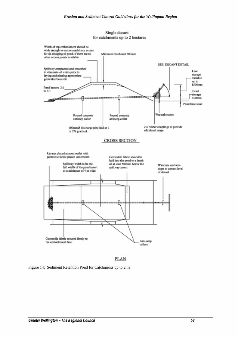
Erosion and Sediment Control Guidelines for the Wellington Region
Greater Wellington – The Regional Council 59
Figure 14: Sediment Retention Pond for Catchments up to 2 ha
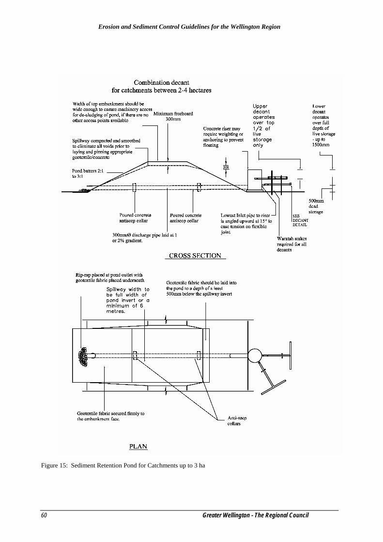
Erosion and Sediment Control Guidelines for the Wellington Region
60 Greater Wellington - The Regional Council
Figure 15: Sediment Retention Pond for Catchments up to 3 ha

Erosion and Sediment Control Guidelines for the Wellington Region
Greater Wellington – The Regional Council 61
5.2 Chemical Flocculation Systems a. Definition
A treatment system designed to add a flocculating chemical to sediment retention ponds.
b. Purpose Used to increase the sediment capture performance of sediment retention ponds by causing suspended sediment to “clump” resulting in faster settling rates.
c. Application
Chemical flocculation systems are used where the performance of sediment retention ponds needs to be increased to reduce the immediate effect of sediment on the receiving environment and/or reduce the cumulative effect of sediment yield within the catchment. Chemical treatment systems are also particularly useful in reducing visual impact (amenity values) and the detrimental effect on water quality resulting from highly turbid discharges (such as dispersive clays).
Management is required as overdosing of flocculant can be just as harmful, if not more so, than the sediment that the system is designed to capture.
There are three systems that can be used for normal earthwork operations plus a number of package systems (self contained re-circulating systems) for specific applications such as tunnelling etc.
Greater Wellington is likely to require a resource consent for the use of chemical flocculation systems. Operators should first contact Greater Wellington before proceeding.
d. Types of Chemical Flocculation System
Batch Dosing
The system is designed to capture stormwater runoff within a sediment retention pond by raising the decanting arms above the spillway. Once the inflow stops liquid flocculant is sprayed across the pond surface using a backpack applicator. After a suitable settling period the decant is lowered and the pond water decanted off. The decant is then raised again pending the next storm runoff event.
This system is useful as a treatment option at the initial stages of an earthworks operation where dispersive clays are often produced. As the operation progresses less weathered silts are likely to be exposed reducing the requirement for flocculation. Using this system a portion of the larger runoff events will not receive flocculant treatment. There is also an element of risk from overdosing as a “crystal clear” sediment retention pond can be perceived as being better than one where there is a little colour left. The risk of overdosing may outweigh the benefits of reduced sediment load.
Erosion and Sediment Control Guidelines for the Wellington Region
62 Greater Wellington - The Regional Council
Rainfall Activated Liquid Dosing
This is an automated system whereby liquid flocculant is introduced to the inflow of a sediment retention pond through rainfall displacement of flocculant from a reservoir. The discharge is maintained as per the standard sediment retention pond decanting outfall allowing all storms to be treated. This has proved a successful and effective treatment option and has a reasonable amount of trial data to support its use. Operators require some training, inspection and re-adjustment is required after every storm and a reasonable amount of care is required. The risk of overdosing is minimal.
Note: The preferred chemical for both batch dosing and rainfall activated systems is poly aluminium chloride (PAC) which is widely used widely as a flocculant for potable water supplies. Aluminium sulphate (Alum) can also be used as a flocculant, however PAC, has less effect on pH levels. This is important when considering overdosing risk and the impact of reduced pH on the aquatic environment.
Flow Activated Dosing
This is an automated system whereby inflow into the sediment retention pond passes over solid “floc blocks” releasing flocculant into the inflow. The system has good potential, particularly for smaller catchments, however, trial data is lacking. With a correctly designed system the risk of overdosing is minimal. The preferred chemical is anionic polyacrylamide (PAM). PAM is a polyelectrolyte with a high affinity for solids reducing the risk of chemical remaining in the discharge in all but the most serious overdosing situations. The Greater Wellington will require a resource consent for the use of PAM.
e. Operating Procedures
Procedure for Batch Dosing
• Use the standard sediment retention pond sizing for the catchment.
• Attach a rope and pulley to the decant arm to allow the arm to be raised above the height of the spillway.
• Determine the volume within the pond to be treated.
• At completion of the runoff event take three one litre samples from the pond and add PAC at 4, 8 and 12mg/L trial aluminium content respectively.
• The following procedure can be used to determine the aluminium dose rate: Liquid PAC obtained from FERNZ Corporation has a aluminium content of 64,164mg/L (10.1% AL2O3 by weight). Dilute this 100:1 with clean water to give an aluminium content of 642mg/L. Add 6.2, 12.5 and 18.7ml to the respective samples and mix, (trial aluminium content divided by 0.642).
• Observe the samples to determine which is the lowest dose rate to give good floc formation within 10-15 minutes. A dose rate between the trial
Erosion and Sediment Control Guidelines for the Wellington Region
Greater Wellington – The Regional Council 63
rates can be chosen to get a lowest dose rate i.e., if 4mg/L gives a poor result however 8mg/L gives an excellent response then 6mg/L is the preferred rate. Some colour should remain in the sample after 1-2 hours.
• Therefore if a dose rate of 4mg aluminium is chosen and a pond volume of 450m3 has been determined then the amount of PAC to be sprayed evenly over the pond surface is 27.9L (0.062 x 450).
• After a settling period of 3-6 hours lower the decant and allow the pond to decant normally.
• After decanting down to the dead storage level raise the decant to above the spillway level in preparation for the next storm event.
• If the appearance of the pond prior to dosing remains similar after further storms then a repeat of the dosing determination is probably not warranted, i.e., continue to dose at the rate chosen. If however, there is a noticeable difference in the turbidity of the pond then further dose determination will be required.
Note: The pond should always be slightly discoloured.
f. Design and Procedure for Automatic Rainfall Activated Liquid Dosing
Operating Principles
A plywood shed is constructed over which a rainfall catch tray is built (see Figure 16). The shed is of sufficient size to contain a open top reservoir (a drum say a metre in diameter by a metre deep) and a header tank (say 0.5m diameter by 0.5m deep) positioned on a shelf over the reservoir. Rain falling on the catch tray is directed to the header tank and from there via a throttling tube to a displacement drum (slightly smaller than the reservoir drum) positioned inside the reservoir drum. The throttling tube allows the unit to continue dosing after the rainfall event stops and more importantly, allows the unit to respond to increased flows as a result of peak intensities through the rainstorm event. The shed should be lockable and sufficiently robust to withstand vandalism (22mm exterior ply is preferred). If vandalism is a major concern, consideration should be given to providing sufficient storage in the shed for spare drums of chemical, (200L) rather than store them alongside the shed.
Procedure
The following design is limited to catchments up to 4 ha. Catchments greater than this will require specialist design. This design assumes a 24 hour 2 year return period storm (50% AEP) of 90mm with a maximum intensity of 40mm/hour. This design provides a degree of flexibility however if the rainfall at the subject site is substantially different from this then a separate analysis will be required.
• Determine the size of the contributing catchment.
Erosion and Sediment Control Guidelines for the Wellington Region
64 Greater Wellington - The Regional Council
• Determine the required dose rate as per bullet points 4-6 in Batch Dosing procedure above.
• Determine the size of the rainfall catch tray according to Table 7 below.
• Determine the size of the header tank. Volume of header tank = 50L x catchment area (ha), 135 litres in the above example.
• Determine position of the header tank low flow outlet pipe (12mm ID garden hose restricted at the outlet to 2mm ID). On a dry clay earthworks site it takes approximately 15mm of rainfall to generate overland flow. Therefore the required volume below the outlet pipe is the area of the rainfall catch tray x 15L, 4.05 x 15L = 60.75L in the above example.
• Determine the position of the high flow outlet pipe (12mm ID garden hose). Time of concentration considerations and experience gained to date suggests the volume between the low flow outlet and the high flow outlet should be 8L/m2 of rainfall tray i.e., (4.05 x 8 = 32.4L for the above example).
• Determine the volume of the reservoir tank. This should be sufficient to provide dosing for the design storm however the larger the tank the less frequent will be the maintenance period (topping up). 150L/ha is a good balance. For the above example the reservoir volume is 2.7 x 150 = 405L. Position the outfall pipe of the reservoir tank at this point. 25% additional volume is provided between the outfall of the reservoir and the top of the displacement tank to provide support for the displacement tank when empty.
• Determine the volume of the displacement tank. This should fit snugly inside the reservoir tank (about 50mm clearance around the sides) and be a similar depth to the reservoir tank.
• Placement of outfall pipe. This pipe should have a minimum ID of 30mm and should run at an even gradient (to minimise air locks). It is to outlet into an area of high inlet energy to facilitate mixing.

Erosion and Sediment Control Guidelines for the Wellington Region
Greater Wellington – The Regional Council 65
Table 7: Aluminium dose rate
Aluminium dose rate
(mg/L/s) Rainfall catch tray area/ha (m2).
2 0.375 4 0.75 6 1.125 8 1.5 10 1.875 12 2.25 14 2.625
Example: For a 2.7 ha catchment with a required dose rate of 8mg/L the rain tray size is 4.05m2 (2.7 x 1.5).
Set up and Servicing.
The header tank is set up with a drain tap at the base to drain off all the water collected once the catchment has dried. This reduces the volume of PAC used and reduces the risk of over dosing. If the catchment remains saturated the header tank is not drained as response times are minimal.
Once the displacement tank is filled to a level where there is insufficient volume remaining to treat a large storm the water is syphoned off and the reservoir tank topped up with chemical to the level of the outfall pipe.
Monitoring
Monitor the pond for the first few rainfall events and periodically throughout the operation to ensure over dosing is not occurring. If the pond dead storage water is clear reduce the size of the catch tray by placing a cover over part of it (say 20% of the rain tray area as a trial). Sample the pH of the outfall and if excessively low (below pH 5.8) consideration should be given to disconnecting the system for at least one storm event. Anticipate reduced chemical requirement as the catchment is progressively stabilised by reducing the rainfall catch tray area accordingly.
Note: For a number of earthwork sites very high sediment loads can be experienced at the beginning of the operation as the more weathered upper horizons (dispersive clays) are exposed. As the operation proceeds, particularly with deep cuts, silt and sand may become predominant, reducing the volume of flocculant required. For this reason pond performance is required at each servicing.
Note: The pond should always be slightly discoloured.

Erosion and Sediment Control Guidelines for the Wellington Region
66 Greater Wellington - The Regional Council
Header Tank
Displacement Tank
Chemical Reservoir
Chemical -Poly aluminium Chloride(PAC) orAluminium Sulphate(Alum)
Accumulated rainwater
Stopcock to emptyheader tank
Low flow outletpositioned toprovide storage for15mm of rainfall.
High flow outletpositioned to providestorage for 25mm ofrainfall
Outlet restriction downto 2 mm to provideextended discharge atthe end of the rainfallevent.
Earth bunding toprovide storage forchemical spillage
SCHEMATICLIQUID CHEMICAL RAINFALL ACTIVATED DOSING SYSTEM
Outfall fromreservoir toinlet channelof thesedimentretentionpond
Rainfall catch tray sized in accordance withthe contributing catchment of the sedimentretention pond
Secure lockablehousing
Figure 16: Schematic of rainfall activated dosing system

Erosion and Sediment Control Guidelines for the Wellington Region
Greater Wellington – The Regional Council 67
g. Design and Procedure for Flow Activated Dosing using Solid Polyelectrolyte
Solid polyelectrolyte floc block is a very effective flocculant and a major advantage of its use is a reduction in the pond settling volume. Pond volumes down to 0.5% (50m3 of storage per 1 ha of contributing catchment) have proved effective.
The major problem with dosing solid polyelectrolyte is variability of flow rate and bed load during a storm. The flume design detailed has evolved through a number of variations and represents the current best practice. However, the design may change as more trial data comes to hand.
Note: The chemical used is polyacryamide and is made from acrylamide which is neurotoxic to mammals. Although the residual acrylamide in polyacrylamide is low (maximum level 0.1%) and is completely degraded by bacteria in surface water it needs to be treated with respect. Wear rubber/plastic gloves at all times when handling this chemical and wash off any chemical that comes into contact with skin.
Flocculant Flume System Figure 17: Sediment retention pond with flocculant flume system

Erosion and Sediment Control Guidelines for the Wellington Region
68 Greater Wellington - The Regional Council
Procedure • Determine the size of the contributing catchment and construct the
appropriate number of flumes.
• Construct a settling pond with a length to wide ratio of between 3:1 and 4:1 with a minimum volume of 0.5% (30% dead storage and maximum depth of 1.5m) with a 0.1% forebay to reduce bed load going through the flume. Ensure easy access to the forebay for regular desludging.
• Ensure inflow energy is spread via a level spreader.
• Position the flume(s) (see Figure 17) on level ground between the forebay and the settling pond and ensure a water tight seal to prevent outflanking and to ensure all flows pass through the flume(s). Tie the flume(s) down to waratahs positioned at each end to prevent movement.
• Position floating decants with a decant rate of 10L/s/ha at the far end of the pond. These decants should be positioned to minimise outlet energy i.e., should extend across the full width of the pond where possible.
• Decant rates can be controlled by the outlet orifice on the decant end cap as stated in Table 8 below.
• Construct a stabilised and level emergency spillway across the full width of the pond.
Table 8: Decant flow rate
Decant flow rate (L/decant) End Cap Orifice (mm)
2.5 35 5 48
7.5 60 10 68
Set up and Servicing
The flume design detailed in Figures 18 and 19 provides optimum dosing for a range of storm events up to and including the 20 year event (5% AEP event). Each flume configuration treats flows from 1 ha of contributing catchment. Each of the holders is to have a hinged lid that is locked to prevent vandalism.
The floc block holders are sealed at the base so that they hold water and after adding the floc blocks the holders are filled with water to the level of the lowest grill holes. This prevents excessive drying out between storms. This water may require to be topped up during long dry spells.
The polyelectrolyte used is Percol AN2 and each of the four floc block holders contain one floc block. If only 0.5 ha is to be treated only two of the holders will contain floc blocks, etc.

Erosion and Sediment Control Guidelines for the Wellington Region
Greater Wellington – The Regional Council 69
Monitoring
Monitor the pond for the first few rainfall events and periodically throughout the operation to ensure over dosing is not occurring. Overdosing should be avoided, - as suspended solid concentration can vary considerably it pays to check periodically for overdosing. A simple test for over-dosing is to mix soil with the discharge from the pond in a jar and compare it for settling rates with a similar amount of soil mixed with water. The dose rate can be adjusted by placing a cover over some of the floc holder grills.
Floc blocks are to be added as they are used up so that at no time are the floc holders to be less than half full with solid floc block.
Note: The pond should always be slightly discoloured.
Disposal of Sludge
Chemical flocculation results in a significant increase in the capture of very fine silts and colloidal clays. This material has a high water content and is therefore difficult to handle. The preferred option is to mix dry soil with the sludge (after decanting off all the ‘cleanwater’) using an excavator and hauling the material to a bunded off area within the site where it can de-water and dry out before incorporation into the fill.

Erosion and Sediment Control Guidelines for the Wellington Region
70 Greater Wellington - The Regional Council
Figure 18: Sediment flocculation flume system – plan and elevation
Figure 19: Sediment flocculation flume system - 3D
5.3 Silt Fence
Plate 14: Silt Fence
a. Definition A temporary barrier of woven geotextile fabric used to intercept sediment laden runoff from small areas of soil disturbance (see Figure 20).
Erosion and Sediment Control Guidelines for the Wellington Region
Greater Wellington – The Regional Council 71
b. Purpose
Silt fences should only be used to intercept sheet flow. Do not use silt fences to reduce the velocity of flows in channels or place them where they will intercept concentrated flow.
c. Application
• On low gradient sites or in confined areas where the contributing catchment is small, i.e., short steep batter fills and around waterbodies.
• To delineate the limit of disturbance on earthworks sites such as riparian areas or bush reserves.
• Do not install silt fences across waterbodies or in areas of concentrated flow.
d. Design
• Excavate a trench (minimum 100mm wide and 200mm deep) along the proposed line of the silt fence. Install the support posts on the downslope edge of the trench and silt fence fabric on the upslope side of the support posts to the full depth of the trench. Backfill the trench with compacted soil.
• Place supporting posts or waratahs approximately 3m apart and 0.4m deep.
• Ensure the top height of the fence is 400mm above ground level.
• To attach fabric, double over and fasten to the support wire and posts with wire ties or cloth fastening clips at 150mm spacings.
• Join lengths of silt fence together by doubling over fabric ends around the supporting posts (wooden posts/battens). Staple the fabric ends to the batten and butt two battens together as shown in Figure 20.
• Maximum slope lengths, spacing of returns and angles for silt fences are shown in Table 9.
• Install silt fence wings at either end projecting upslope to a sufficient height to prevent outflanking.

Erosion and Sediment Control Guidelines for the Wellington Region
72 Greater Wellington - The Regional Council
Table 9: Silt fence design criteria
Slope (%)
Slope Length (m) Spacing of Returns (m)
Length (m)
<2% Unlimited N/A Unlimited 2-10% 40 60 300 10-20% 30 50 230 20-33% 20 40 150 33-50% 15 30 75 >50% 6 20 40
e. Construction Considerations
• Always install silt fences along the contour. Where this is not possible or where there are long sections of silt fence, install short silt fence returns projecting upslope from the main fence to minimise concentration of flows. Silt fence returns are a minimum 2m in length and can incorporate a tie back. They are constructed by continuing the silt fence around the return and doubling back, eliminating joins.
• Where impounded flow may overtop the silt fence make provision for a rip-rap splash pad or other outlet protection device.
• If water ponds behind a silt fence, provide extra support with tie backs from the silt fence to a central stable point on the upward side. Extra support can also be provided by stringing a wire between support stakes and connecting the filter fabric to this wire.
• Use supporting posts of tanalised timber (50mm x 50mm), or steel waratahs at least 1.5m in length.
• Reinforce the top of the silt fence fabric with a wire support made of galvanised wire (minimum diameter of 2.5mm). Tension the wire using permanent wire strainers attached to angled waratahs at the end of the silt fence.
• Use of silt fences in catchments of more than 0.5 ha requires consideration of other site control measures.
f. Maintenance
• Inspect silt fences at least once a week and after each rainfall.

Erosion and Sediment Control Guidelines for the Wellington Region
Greater Wellington – The Regional Council 73
• Make any necessary repairs when bulges occur or when sediment accumulation reaches half way up the fabric height. Remove sediment deposits as necessary to a secure area.
• Any areas of collapse, decomposition or ineffectiveness need to be replaced.
• Do not remove the silt fence until the catchment area has been stabilised.
• When the silt fence is removed stabilise the area occupied by the fence.
Figure 20: Silt fence

Erosion and Sediment Control Guidelines for the Wellington Region
74 Greater Wellington - The Regional Council
5.4 Super Silt Fence
Plate 15: Super Silt Fence a. Definition
• A temporary barrier of woven geotextile fabric over chain link fence used to intercept sediment laden runoff from soil disturbance in small catchment areas (see Figure 21).
b. Purpose
• A super silt fence provides more robust sediment control compared with a standard silt fence and allows up to four times the catchment area to be treated by an equivalent length of standard silt fence.
c. Application
• Provides a barrier that can collect and hold debris and soil, preventing material from entering receiving environments.
• May be used where the installation of an earth or topsoil bund (see Section 5.6) would destroy sensitive areas, i.e., bush and wetlands.
• Super silt fences should be placed as close to the contour as possible. No section of the fence should exceed a grade of 5% for a distance of more than 15m.
Erosion and Sediment Control Guidelines for the Wellington Region
Greater Wellington – The Regional Council 75
d. Design
• When considering super silt fence installation for larger catchments (greater than 0.5 ha) consider the specific site conditions and other alternative control measures available. Base the length of the super silt fence on the limits shown in Table 10.
• Ultraviolet light affects the stability of the fabric and will dictate the maximum period that the super silt fence may be used.
• Where ends of the geotextile fabric come together, overlap, fold and staple the fabric ends to prevent sediment bypass.
Table 10: Super silt fence design criteria
Slope % Slope Length (m)
Length (m)
0-10 Unlimited Unlimited 10-20 60 450 20-33 30 300 33-50 30 150 >50 15 75
e. Construction Considerations
• Use a fabric that is appropriate to the site conditions and complies with the manufacturers specifications.
• Excavate a trench 100mm wide by 200mm deep along the line of the super silt fence.
• Position posts ( No. 3 rounds, No 2 half rounds or waratahs) every 3m on the downslope side of the trench. Posts are not required to be set in concrete and should be approximately 1.8m in length and depth of 1m.
• Install tensioned galvanised wire (2.5mm HT) at 400mm and 800mm above ground level using permanent wire strainers.
• Secure chain link fence to the fence posts with wire ties or staples. Make sure the chain link fence goes to the base of the trench.
• Fasten two layers of geotextile fabric securely to the super silt fence with ties spaced every 600mm at the top and mid section of the super silt fence. Place the two layers of geotextile fabric to the base of the trench (a minimum of 200mm into the ground) and place compacted backfill back to the original ground level.
• When two sections of geotextile fabric adjoin each other, ensure they are doubled over at least 300mm. The fabric should be wrapped around a batten and stapled at 75mm spacing to prevent sediment escapes.
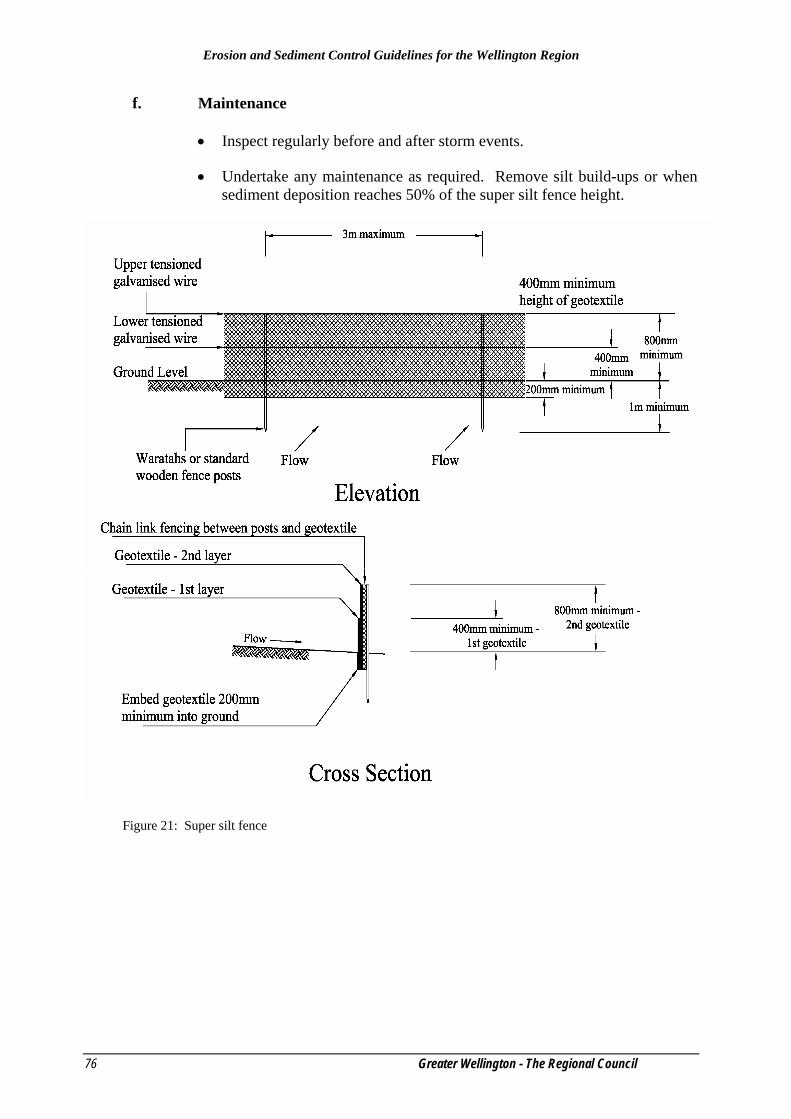
Erosion and Sediment Control Guidelines for the Wellington Region
76 Greater Wellington - The Regional Council
f. Maintenance
• Inspect regularly before and after storm events.
• Undertake any maintenance as required. Remove silt build-ups or when sediment deposition reaches 50% of the super silt fence height.
Figure 21: Super silt fence

Erosion and Sediment Control Guidelines for the Wellington Region
Greater Wellington – The Regional Council 77
5.5 Stormwater Inlet Protection a. Definition
• A barrier across or around a cesspit (stormwater inlet) (see Figure 22).
b. Purpose
• To intercept and filter sediment-laden runoff before it enters a reticulated stormwater system via a cesspit, thereby preventing sediment-laden flows from entering receiving environments. The protection may take various forms depending upon the type of inlet to be protected. Stormwater protection is a secondary sediment control device. It must only be used in conjunction with other erosion and sediment control measures unless no other option exists.
c. Application
• Do not use stormwater inlet protection as a primary method of treatment.
• Use only in catchments less than 0.5 ha in area.
• Use only where it is not possible to temporarily divert the storm drain to a permanent sediment retention facility.
Stormwater inlet protection provides at best limited sediment retention. Use additional measures up-slope, such as topsoil bunds and cut-off drains, to minimise the volume of sediment reaching any stormwater inlet. Cesspits must be able to convey flow from the site to prevent large concentrated highly erosive flows from building up and causing washouts in secondary overland paths.
Stormwater systems are, by design, very efficient at conducting flows away from inlets and therefore once sediment reaches the stormwater system it will be discharged directly to the receiving environment. Therefore, the need to use stormwater inlet protection indicates poor erosion and sediment control and/or inadequate stabilisation of the site.
d. Design
There are various design options for reducing sediment inputs to the stormwater cesspits.
• A silt fence can be erected around the inlet (see Section 5.3). This method is appropriate where cesspits have been connected to a stormwater system and are collecting runoff from disturbed soil surfaces.
• Two common methods use geotextile and gravel to treat sediment-laden flows. All points where runoff can enter the cesspit must be protected with suitable geotextile fabric.

Erosion and Sediment Control Guidelines for the Wellington Region
78 Greater Wellington - The Regional Council
− Wrap geotextile fabric around the cesspit grate as a barrier to flow from the roadside gutter. Inspect the inlet above the grate back of the cesspit where a geotextile fabric sock filled with gravel must be placed to intercept runoff.
− Lay coarse geotextile fabric over the cesspit and up onto the kerb with a layer of aggregate material to act as a primary filter to hold the fabric in place.
• Place a series of low sandbag check dams upstream from the cesspit to act
as a series of sediment traps. The sandbags require a spillway lower than the kerb to ensure that runoff does not encroach onto the berm area and cause scouring. Configure the sandbags in a arc pattern with no gaps away from the kerb to create a series of impoundment areas.
• Excavating around a stormwater inlet creates storage capacity where suspended material can settle out. Ensure that seepage holes allow for filtered dewatering and that the capacity provided around the inlet for storage is a minimum of 1% of the catchment (l m3 of capacity per 100m2 of contributing catchment).
e. Maintenance
• Maintenance requirements are high because they tend to clog quickly. If clogging occurs, remove accumulated sediment and clean or replace the geotextile fabric and aggregate.
• Inspect stormwater inlet protection measures following any rainfall event and maintain as necessary to ensure they operate effectively.

Erosion and Sediment Control Guidelines for the Wellington Region
Greater Wellington – The Regional Council 79
Figure 22: Stormwater inlet protection – filter media design
Erosion and Sediment Control Guidelines for the Wellington Region
80 Greater Wellington - The Regional Council
5.6 Decanting Earth Bund
a. Definition
• A temporary berm or ridge of compacted earth constructed to create impoundment areas where ponding of runoff can occur and suspended material can settle before runoff is discharged (see Figure 23).
b. Purpose
• Used to intercept sediment-laden runoff and reduce the amount of sediment leaving the site by detaining sediment-laden runoff.
c. Application
• Earth bunds can be constructed across disturbed areas and around construction sites and subdivisions. Keep them in place until the disturbed areas are permanently stabilised or adequately replaced. Earth bunds are particularly useful for controlling runoff after topsoiling and grassing before vegetation becomes established. Where works are occurring within the berm area, compact the topsoil over the berm area as a bund adjacent and parallel to the berm. This will act as an impoundment area and controlled outfall while also keeping overland flow away from the construction area.
d. Design
• Earth bunds require a constructed outlet structure and spillway as specified for sediment retention ponds (see Section 5.1). Alternatively, construct an outlet of perforated pipe connected to a non-perforated pipe that passes through the earth bund and either discharges to a gutter or directly to a stormwater inlet. The section of pipe within the impoundment area should be supported by means of a rigid post, allowing filtration to occur.
• Make sure the top opening of the perforated pipe is 150mm lower than the stabilised spillway.
• The section of pipe leading through the earth bund and continuing downslope below the earth bund is non-perforated.
• The maximum contributing catchment should not exceed 0.3 ha.
• Position the decant inlet to provide 5% live storage volume with a minimum distance of 5m of flat ground (or under vertical) from the outlet. Otherwise raise the outlet so the dead storage level extends out at least this far.
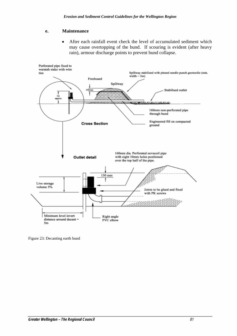
Erosion and Sediment Control Guidelines for the Wellington Region
Greater Wellington – The Regional Council 81
e. Maintenance
• After each rainfall event check the level of accumulated sediment which may cause overtopping of the bund. If scouring is evident (after heavy rain), armour discharge points to prevent bund collapse.
Figure 23: Decanting earth bund
Erosion and Sediment Control Guidelines for the Wellington Region
82 Greater Wellington - The Regional Council
5.7 Decanting Topsoil Bund
a. Definition
• A temporary berm or ridge of track rolled topsoil, constructed to create impoundment areas where ponding of runoff can occur and suspended material can settle before runoff is discharged.
b. Purpose
• Used to intercept sediment-laden runoff from small areas (less than 0.3 ha) and reduce the amount of sediment leaving the site by detaining sediment-laden runoff.
c. Application
• Topsoil bunds can be constructed across disturbed areas and around construction sites and subdivisions. They are generally constructed along the limit of disturbance using topsoil stripped from the immediate area. Topsoil bunds can also function as stockpiles pending re-spreading at the completion of earthworks.
• Topsoil bunds are also useful for controlling runoff after topsoiling and seeding before vegetation becomes established. Where works are occurring within the berm area, compact the topsoil as a bund adjacent and parallel to the berm. This will act as an impoundment area while also keeping overland flow away from the service installation works within the berm area.
d. Design
• Topsoil bunds should at least 4m wide by 1.5m high minimum.
• For adequate compaction track roll every 200mm lift of topsoil.
• Topsoil is more erodible than cohesive mineral soils therefore additional measures will be required to make sure there is a stabilised emergency spillway. The spillway should be well compacted, have no voids and have two layers of geotextile (UV stable impermeable weave over a soft permeable mat) pinned at 0.5m centres.
• Topsoil bunds require a decanting device, constructed of perforated novacoil connected to a non-perforated pipe that passes through the topsoil bund. This should either discharge to a gutter or directly to a stormwater inlet. Ensure the section of pipe within the impoundment area is supported by means of a rigid upstand (waratah) allowing decanting to occur.
• Make sure the top opening of the perforated pipe is 200mm lower than the stabilised spillway.
• The freeboard above the spillway invert is at least 400mm.

Erosion and Sediment Control Guidelines for the Wellington Region
Greater Wellington – The Regional Council 83
• Construct the topsoil bund such that the maximum contributing catchment does not exceed 0.3 ha.
e. Maintenance
• Inspect and maintain topsoil bunds regularly and after each rainfall event check for accumulated sediment which may cause overtopping. Check for scouring and install further armouring or other stabilisation if scouring is evident.

Erosion and Sediment Control Guidelines for the Wellington Region
84 Greater Wellington - The Regional Council
5.8 Sump / Sediment Pit
Plate 16: Sump /Sediment Pit
a. Definition
A temporary pit which is constructed to trap and filter water before it is pumped to a suitable discharge area (see Figure 24).
b. Purpose
To treat sediment-laden water that has been removed from areas of excavation or areas where ponded sediment-laden water cannot drain by other means.
c. Application
• When water collects during the excavation phase of construction.
• Particularly useful in urban areas during excavation for building foundations.
• May be used to dewater sediment retention measures.
d. Design
• Place a perforated vertical standpipe placed in the centre of a pit which is backfilled with aggregate.
• Determine the number of sump/sediment pits and their locations on site in accordance with the required dewatering facilities and procedures outlined below.
• Pump water from the centre of the pipe to a suitable discharge area.

Erosion and Sediment Control Guidelines for the Wellington Region
Greater Wellington – The Regional Council 85
• Direct the discharge to an appropriate outlet.
• If the water is pumped directly to the receiving environment, wrap a geotextile fabric around the standpipe to achieve a clean water discharge. When a geotextile fabric is used, the surface area of the standpipe will need to be increased and the pumping rate decreased to prevent the geotextile becoming rapidly blocked.
• Sump/sediment pit dimensions are variable, but require a minimum depth of 1m and a minimum volume of 2m3.
• Construct the standpipe from 300-600mm diameter pipe with a grid of 10mm diameter perforations at 60mm spacings along the standpipe.
• Place a base of 50mm aggregate in the sump/sediment pit to a depth of 300mm.
• After placing the standpipe in position backfill the area with 80mm aggregate.
• Extend the standpipe 300m m above the lip of the sump/sediment pit with the aggregate extended 100mm above the anticipated standing water elevation.
e. Maintenance
Undertake ongoing checks throughout the use of the sump/sediment pit to ensure effective operation. For isolated areas where dewatering must occur to facilitate progress, other methods may be appropriate, which include:
• Pumping accumulated sediment-laden water to a sediment retention pond.
• Constructing a silt fence and pumping water to behind the silt fence to be retained for treatment. Do not let water to be treated enter the silt fence as a concentrated flow or outflank the silt fence.
• Discharge accumulated sediment-laden water to land where soakage may occur. Ensure that this untreated sediment-laden runoff cannot enter a stormwater system or any waterbody.

Erosion and Sediment Control Guidelines for the Wellington Region
86 Greater Wellington - The Regional Council
Figure 24: Sump/sediment pit
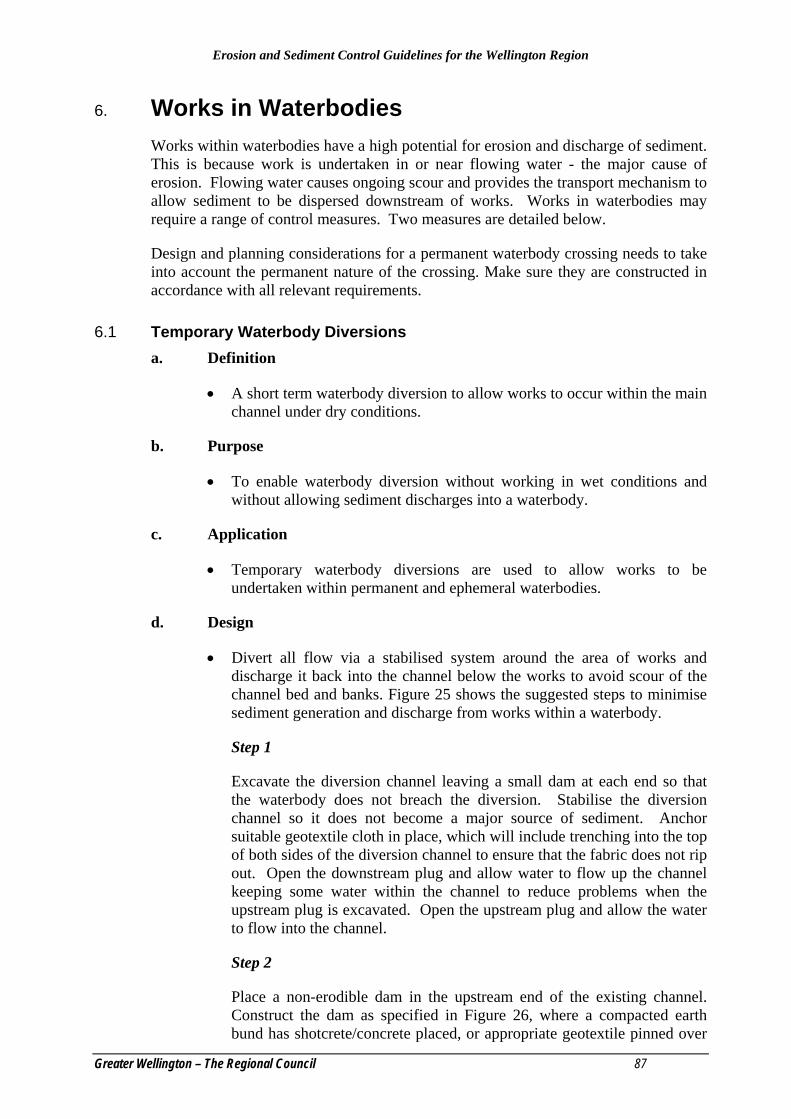
Erosion and Sediment Control Guidelines for the Wellington Region
Greater Wellington – The Regional Council 87
6. Works in Waterbodies Works within waterbodies have a high potential for erosion and discharge of sediment. This is because work is undertaken in or near flowing water - the major cause of erosion. Flowing water causes ongoing scour and provides the transport mechanism to allow sediment to be dispersed downstream of works. Works in waterbodies may require a range of control measures. Two measures are detailed below.
Design and planning considerations for a permanent waterbody crossing needs to take into account the permanent nature of the crossing. Make sure they are constructed in accordance with all relevant requirements.
6.1 Temporary Waterbody Diversions a. Definition
• A short term waterbody diversion to allow works to occur within the main channel under dry conditions.
b. Purpose
• To enable waterbody diversion without working in wet conditions and without allowing sediment discharges into a waterbody.
c. Application
• Temporary waterbody diversions are used to allow works to be undertaken within permanent and ephemeral waterbodies.
d. Design
• Divert all flow via a stabilised system around the area of works and discharge it back into the channel below the works to avoid scour of the channel bed and banks. Figure 25 shows the suggested steps to minimise sediment generation and discharge from works within a waterbody.
Step 1
Excavate the diversion channel leaving a small dam at each end so that the waterbody does not breach the diversion. Stabilise the diversion channel so it does not become a major source of sediment. Anchor suitable geotextile cloth in place, which will include trenching into the top of both sides of the diversion channel to ensure that the fabric does not rip out. Open the downstream plug and allow water to flow up the channel keeping some water within the channel to reduce problems when the upstream plug is excavated. Open the upstream plug and allow the water to flow into the channel.
Step 2
Place a non-erodible dam in the upstream end of the existing channel. Construct the dam as specified in Figure 26, where a compacted earth bund has shotcrete/concrete placed, or appropriate geotextile pinned over
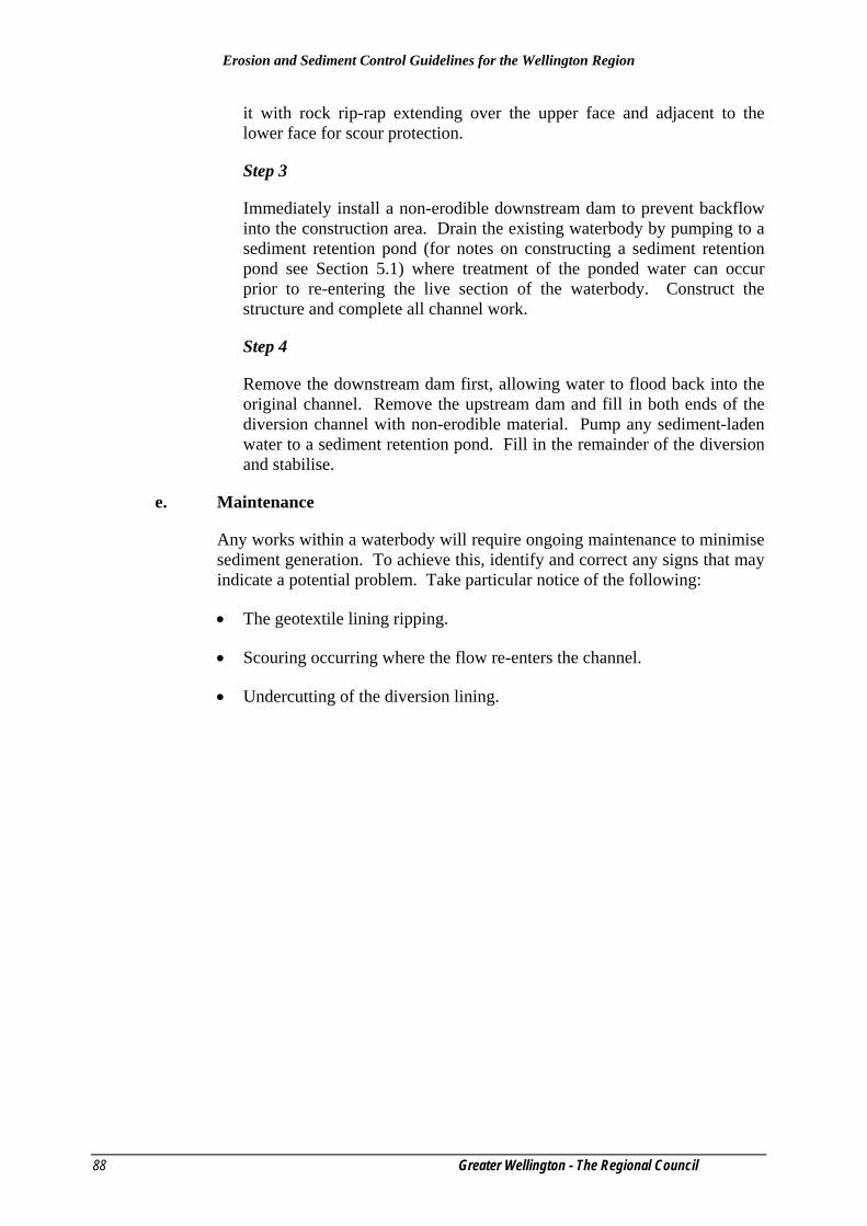
Erosion and Sediment Control Guidelines for the Wellington Region
88 Greater Wellington - The Regional Council
it with rock rip-rap extending over the upper face and adjacent to the lower face for scour protection.
Step 3
Immediately install a non-erodible downstream dam to prevent backflow into the construction area. Drain the existing waterbody by pumping to a sediment retention pond (for notes on constructing a sediment retention pond see Section 5.1) where treatment of the ponded water can occur prior to re-entering the live section of the waterbody. Construct the structure and complete all channel work.
Step 4
Remove the downstream dam first, allowing water to flood back into the original channel. Remove the upstream dam and fill in both ends of the diversion channel with non-erodible material. Pump any sediment-laden water to a sediment retention pond. Fill in the remainder of the diversion and stabilise.
e. Maintenance
Any works within a waterbody will require ongoing maintenance to minimise sediment generation. To achieve this, identify and correct any signs that may indicate a potential problem. Take particular notice of the following:
• The geotextile lining ripping.
• Scouring occurring where the flow re-enters the channel.
• Undercutting of the diversion lining.

Erosion and Sediment Control Guidelines for the Wellington Region
Greater Wellington – The Regional Council 89
Figure 25: Temporary waterbody diversion works sequence

Erosion and Sediment Control Guidelines for the Wellington Region
90 Greater Wellington - The Regional Council
Figure 26: Temporary waterbody diversion dam detail

Erosion and Sediment Control Guidelines for the Wellington Region
Greater Wellington – The Regional Council 91
6.2 Temporary Waterbody Crossings a. Definition
A bridge, culvert or ford installed across a waterbody for short-term use.
b. Purpose
To provide a means to cross waterbodies without moving sediment into the waterbody, damaging the bed or channel, or causing flooding during the construction, maintenance or removal of the structure.
c. Application
Where heavy equipment is required to be moved from one side of a waterbody to the other, or where traffic must cross the waterbody frequently for a short period of time.
d. Design
• Planning can minimise the requirement for waterbody crossings. Wherever possible, avoid crossing waterbodies by completing the development separately on each side of the channel thus leaving the waterbody in its natural state. If no other option exists and a waterbody crossing is required, select a location where the potential effects of the crossing (including construction) are minimised.
• Plan waterbody crossings before they are required and construct them during periods of dry weather. Complete construction as rapidly as possible and stabilise all disturbed areas immediately during and following construction.
• There are three main types of crossing; bridges, culverts and fords.
− Where available materials and designs are adequate to bear the expected loadings, bridges are the preferred temporary waterbody crossing method. They provide the least obstruction to flow and fish migration, cause little or no modification of the bed or banks and generally require little maintenance.
− It should be noted, however, that bridges can be a safety hazard if not designed, installed and maintained appropriately.
− Culverts are the most commonly used type of temporary waterbody crossing and can be easily adapted to most site conditions. The installation and removal of culverts, however, causes considerable damage to waterbodies and can also create the greatest obstruction to flood flows.
− Fords are often used in steep catchments subject to flooding, but where normal flows are shallow. Only use fords where crossing requirements are infrequent. They can offer little or no obstruction to flows, are relatively easy to install and maintain and in most cases can be left in place at the end of the construction activity.

Erosion and Sediment Control Guidelines for the Wellington Region
92 Greater Wellington - The Regional Council
• As well as erosion and sediment control measures, structural stability, utility and safety must also be taken into account when designing temporary waterbody crossings.
• When the structure is no longer needed, remove the structure and all material from the site. Immediately stabilise all areas disturbed during the removal process by revegetation or artificial protection as a short-term control measure. Keep machinery clear of the waterbody while removing the structure.
e. Maintenance
• Inspect temporary waterbody crossings after rain to check for blockage in the channel, erosion of the banks, channel scour or signs of Instability. Make all repairs immediately to prevent further damage to the installation.

Erosion and Sediment Control Guidelines for the Wellington Region
Greater Wellington – The Regional Council 93
7. Quarries Quarries are places of naturally occurring hard rock that is mined for rock and gravels. The products from quarry operations are used for roading, building and in rock protections measures, i.e., rip-rap.
Quarries tend to have large areas which are left open for long periods of time and these can be exposed to erosion (wind action and rain). Quarries are also places of continuous machinery operation where the conditions (placement of rock and gravel) within the quarry can change on a daily basis. For these reasons it is important that quarries are well managed to minimise the movement of sediment into waterways.
For many quarry operations a Quarry Management Plan is produced. This plan sets out the operational (day-to-day) functions of a quarry. One of the important functions this plan should cover is the management of the quarry to minimise erosion and sedimentation. Sections 3, 4 and 5 of these Guidelines may assist quarry operators with the methods and techniques used for minimising erosion from quarry operations.
The following specific issues associated with quarry operations:
• Road access • Stormwater • Overburden disposal • Stockpile areas • Rehabilitation of worked out areas • Riparian protection areas • Maintenance schedule for erosion and sediment control treatment structures.
7.1 Road Access Many quarries are serviced by all weather metal roads. During rain, heavy vehicle movements on metal roads can generate substantial amounts of sediment that can migrate towards waterways and other drainage systems within the quarry. This sediment should be controlled within the quarry operation. These roads, however are not always within the designated quarry area and may not be covered by a Quarry Management Plan. Consideration should be given to managing roads and traffic for sediment control. Where possible, incorporate road access into the Quarry Management Plan making sure all control measures are put in place to protect receiving environments.
7.2 Stormwater
7.2.1 Cleanwater Runoff Divert clean water flow away from working and bare areas to prevent it becoming contaminated by sediment. This will reduce the volume of contaminated runoff requiring control and treatment. Runoff diversion channels around the working site, as outlined in Section 4.1, are the simplest way to deal with cleanwater runoff.
Erosion and Sediment Control Guidelines for the Wellington Region
94 Greater Wellington - The Regional Council
7.2.2 Contaminated Runoff Any runoff from bare areas will collect sediment and become contaminated. This contaminated runoff, which may include runoff from aggregate wash processes, must be contained and treated in an appropriate manner before being discharged to natural waterbodies. The Quarry Management Plan must detail the methods for containment and treatment of all contaminated runoff. Particular attention should be paid to sensitive areas such as permanent waterbodies, waterbody crossings and steeply sloping bare areas. Design all structures for the 5% AEP rainfall event.
7.3 Overburden Disposal Methods of overburden disposal vary for each quarry operation. Overburden removal and disposal sites can be a major source of erosion and sediment discharges from quarries, particularly if the disposal site is not properly located and managed. The Quarry Management Plan should give details on:
• The timing and extent of overburden stripping, which will be related to an expected volume and area of extraction.
• The methods to be employed for disposing the overburden.
• Ongoing management of disposal sites, including provision for regular disposal of material trapped in sediment retention ponds.
• If overburden disposal is not part of a Quarry Management Plan, consideration must be given to the following points:
• Selection of disposal site (why the site was chosen)
• Stability of the site and subsequent overburden fill (batter slopes, safety factors, benching, underlying material, drainage).
• Erosion and sediment control measures.
• Rehabilitation of disposal site (revegetation, contouring).
7.4 Stockpile Areas Stockpile areas are used for stockpiling both for raw or finished quarry products prior to further processing or final dispatch. These areas can be a major source of contaminated runoff if not properly controlled. Position stockpiles well away from any waterbodies and runoff flow paths.
7.5 Rehabilitation of Worked Out Areas Planning for rehabilitation must be an integral part of all quarry operations. A properly planned and implemented rehabilitation programme will reduce the need for expensive ongoing erosion control and treatment of contaminated runoff. The aim of site rehabilitation, whether temporary or permanent, is to maintain the site in a condition so that erosion and contaminated runoff are minimised. The prime areas for consideration are:
• Establishing suitable final ground contours.

Erosion and Sediment Control Guidelines for the Wellington Region
Greater Wellington – The Regional Council 95
• Establishing a suitable environment for vegetation growth.
• Revegetating the site with suitable vegetation cover.
7.6 Riparian Protection Areas Riparian protection areas rely on vegetation to provide a buffer between the quarry operations and a waterbody. These margins act as a physical barrier and as a last resort sediment trap for diffuse runoff and/or unforeseen discharges. Do not, however, rely on riparian protection areas as a primary sediment control mechanism.
7.7 Maintenance Schedule for Erosion and Sediment Control or Treatment Structures
Because quarry operations continue over a long time frame, it is important to develop a maintenance schedule for any control/treatment structures. Resources allocated on designing and constructing control/ treatment structures will be wasted if structures are not adequately maintained.
Properly maintained structures should provide optimum performance at all times, minimising the adverse environmental effects of the quarry operation. Conversely, poorly maintained structures are likely to result in unsatisfactory environmental protection despite initially being well designed and constructed.
Operators should develop a maintenance schedule that clearly indicates what is to be achieved in terms of visual inspections and maintenance works. Undertake routine maintenance works when they will cause the least possible detrimental environmental effects (either directly or indirectly). For example, do not clean sediment retention ponds during or immediately after rainfall events.
It is important that all control/treatment structures are inspected after significant rainfall events, or during prolonged rainfall, in addition to any regular scheduled inspections. In the maintenance schedule include a procedure for immediately repairing and remedying any damage caused to control/ treatment structures from daily quarry activities.
In overall quarry operations, place inspection and maintenance of control/treatment structures as a high priority. Ensure that every person involved in the operation is familiar with all aspects of erosion and sediment control, including any special consent conditions. For example, specific water quality sampling requirements.
For all aspects of quarry operations where erosion and sediment controls are required, install the erosion and sediment control practices as specified in these Guidelines.

Erosion and Sediment Control Guidelines for the Wellington Region
96 Greater Wellington - The Regional Council
8. Forestry Operations Forestry operations can include large scale earthworks with tracking, roading and landing (skid site) formation, as well as the direct disturbance and exposure of the soil surface. Operational planning is required to make sure that these operations are carried out with minimal environmental impact. To find out more about minimising impacts from forestry operations see Sections 4 and 5 of these Guidelines. Forestry operators may be required to produce harvest management plans that cover the various aspects of their operation.
The various specific issues associated with forestry operations are outlined below:
• Roading • Firebreaks • Landings and tracks • Land preparation • Harvesting and management after harvesting
8.1 Roading Roading activities undertaken as part of forestry operations can have a large impact on soil and water values.
8.1.1 Planning, Location and Design
• Locate roads on ridge tops, natural benches and flatter slopes, avoiding where possible steep sided slopes.
• Do not locate roads in gully bottoms.
• Minimise gully crossings where possible.
• Locate roads a safe distance from waterbodies and gullies.
• Do not discharge runoff directly to a waterbody and where possible ensure sediment-laden runoff is treated prior to discharge.
• Where steep side cuts cannot be avoided, make sure adequate cross-formation drainage is installed and that these channels flow onto stable or erosion proof areas such as spurs. Make sure channels do not discharge onto areas of fill.
8.1.2 Construction
• Where construction operations are to be undertaken in erosion-prone areas or adjacent to waterbodies, use an excavator to move soil and other loose material. The moved material should be placed in a stable condition to prevent further runoff.
• Do not bulldoze loose material into waterbodies or areas where it may wash into waterbodies.
• Keep machines out of waterbodies and minimise the number of crossings.

Erosion and Sediment Control Guidelines for the Wellington Region
Greater Wellington – The Regional Council 97
• If operations are suspended put adequate drainage provisions in place to avoid concentration of runoff and scour problems until work resumes.
• Stabilise cut and fill slopes where required. Use measures such as benching, straw mulching and hydroseeding (see Section 4.10).
• Install contour drains and drop structures to prevent scouring (see Sections 4.1, 4.5).
• Flume or pipe runoff to solid ground and then onto logging slash, gravel, rock rip-rap, or geotextiles.
• Plan the installation of culverts and bridges across waterbodies. All materials, machinery and labour should be on hand before commencing construction.
• Supervision of culvert and bridge installations is to be carried out by suitably qualified persons.
• Complete the construction of waterbody crossings, approach roads and associated erosion and sediment control measures as a continuous operation.
8.2 Firebreaks • Locate firebreaks to minimise the possibility of debris entering waterbodies.
• Keep earthworks associated with firebreaks clear of steep drop-offs and waterbodies. Consideration must be given to the erosion potential of tracks formed along gully bottoms. These areas should be avoided.
• Maintain firebreaks to a reasonable standard to control runoff, rilling and gully erosion.
• Construct contour drains as required.
• Avoid ponding of water above steep drop-offs, if ponding occurs, implement a appropriate drainage design to prevent gully erosion.
• At the completion of operations, inspect firebreaks for any potential erosion problems.
8.3 Land Preparation 8.3.1 Planning
Plan all land preparation and forest establishment to match an appropriate proposed method of harvesting.
8.3.2 Protection Areas (Riparian Margins) Retain or establish protection areas along all waterbodies. Where protection areas do not exist, they can be established in conjunction with the following operations:
• Land clearing or site preparation on areas being converted to production forestry.
Erosion and Sediment Control Guidelines for the Wellington Region
98 Greater Wellington - The Regional Council
• Planting on farmland or similar sites.
• Replanting on exotic clearfelled areas.
Re-evaluate all existing protection areas when harvesting or replanting adjacent to production stands. Protection areas can be left to regenerate naturally. In some cases it may be appropriate to accelerate revegetation by actively planting protection species.
8.3.3 Planting Boundaries Establish planting boundaries back from waterbodies in order to minimise potential waterbody damage from future harvesting operations. Plant boundaries with consideration of both topography and soil stability.
8.3.4 V-Blading/Line Raking Where possible operate machinery across contours to minimise runoff moving down blade lines. If downhill runs are unavoidable, limit these to 50m maximum length. Do not attempt machinery runs on steep slopes that prevent machinery from reversing uphill. Blade or rake at least one line on the contour along the lower boundary of downhill operations to prevent runoff concentration at low points or gully systems. Finish downhill runs before any fill batter slopes such as landings and access roads. In areas adjacent to waterbodies, ensure machinery runs parallel to waterways and keep a practical minimum distance of 50m. At the completion of the operation, inspect the site for areas of erosion potential and undertake appropriate remedial action.
8.3.5 Establishing and Tending During establishing and tending stages, minimise soil loss and prevent contamination of waterbodies from chemical fertilisers, debris or detritus. During thinning operations, fell trees away from waterbodies.
8.4 Harvesting and Management After Harvesting
8.4.1 Planning of Logging Operations Plan all logging operations, particularly the location of skid tracks and roads, to protect water quality and soil structure. Off-site adverse effects must be avoided or minimised when planning the catchment to be harvested. Plan your logging operation to minimise disturbance of sensitive ecological areas.
8.4.2 Felling Operations Where possible, fell trees away from waterbodies. Extract any trees that have fallen into waterbodies before de-limbing and heading. Back pull, or employ other acceptable directional felling techniques to fell problem trees, particularly on steep or unstable waterbody faces and edges. Remove all large logging debris from waterbodies at the completion of the operation, keeping machinery out of waterbodies.

Erosion and Sediment Control Guidelines for the Wellington Region
Greater Wellington – The Regional Council 99
8.4.3 Extraction Operations Ground Based Systems • Keep tracking and stumping activities to a practical minimum. Use established
tracks rather than making shortcut tracks, which cause unnecessary ground disturbance.
• Carry logs off the ground or on the machine where possible.
• Keep the machine blade up and do not bulldoze soil and stumps unnecessarily.
• Do not cross waterbodies (other than at approved crossing points) and do not haul along them.
• On soft and/or wet soils or steeper slopes, use low-ground, pressure machines such as flexible-track or wide-tyre skidders.
Cable Systems
Where cable systems are used in environmentally sensitive areas keep the settings small, the haul distances short and the hauling direction uphill wherever practicable. Avoid cross slope haul lines that damage protected areas or sweep slash and soil into waterbodies.
Wherever possible, when hauling across waterbodies, use a skyline system, which allows full log suspension. Lift logs clear of waterbody banks and protection areas.
8.4.4 Cleanup Operations On completion of logging operations, carry out the following procedures:
• Remove all temporary crossings.
• Construct water cut-offs on skid tracks to prevent runoff concentration and sediment flow.
• Stabilise side cut tracks with slash where possible.
• Stabilise fill batters on landings and tracks by sowing with suitable grass seed.
• Runoff is channelled safely over batter slopes and onto stable areas.
8.5 Landings and Tracks Landings and tracks are permanent features that require preparation, direction of fall and runoff control. Skid tracks, tend to be a temporary feature, but both types of structure require consideration of the following:
• Minimise erosion by tracking across contours and where possible, locating tracks on ridges rather than in gullies.
• Extraction tracks should not lead directly down towards waterbodies where runoff may go directly into a channel.

Erosion and Sediment Control Guidelines for the Wellington Region
100 Greater Wellington - The Regional Council
• Attempt to keep skid tracks and landings at least 50m away from waterbodies.
• At the completion of logging operations, construct water cut-offs across skid tracks. Water cut-offs should discharge to solid ground and not to areas of fill.
• Keep landings well clear of permanent waterbodies. Where no alternative exists make sure waterbodies are not obstructed.
• Form all landings to prevent surface runoff flowing down towards or directly into a waterbody.
• Construct earth bunds along waterbody edge boundaries to prevent debris and sediment from entering waterbodies.
• Caution must be exercised in the planning and construction of erosion control measures that minimise runoff from skid tracks onto landings.
Take extra caution when forming landings in dry gullies. When complete ensure the following:
• Controls are placed across the gully floor to treat sediment-laden flows, e.g., a decanting earth bund (see Section 5.6).
• Fill batters are sown with a suitable vegetation cover.

Erosion and Sediment Control Guidelines for the Wellington Region
Greater Wellington – The Regional Council 101
9. Other types of land disturbing activities The following is a brief summary of key considerations for minimising adverse environmental effects of land disturbing activities not found in the detailed description of erosion and sediment control measures described in Sections 4 and 5.
9.1 Trenching Trenching (usually for installing utility services), often occurs at the end of bulk earthworks. The following points need to be considered when trenching:
• The project needs to be undertaken in appropriately sized stages so the area exposed can be fully stabilised within an acceptable time frame.
• If trenching impacts on existing erosion and sediment control measures that are part of the overall development, those measures should be reinstated as soon as possible. Contingency measures should be put in place until the original measures are reinstated or replaced.
• All trenching operators working within a larger site are familiar with the overall erosion and sediment control plan for the site and can comply with this plan.
• Independent erosion and sediment control measures such as those detailed in these Guidelines should be employed for the trenching operation.
• Topsoil and sub-soils should be stockpiled separately adjacent to the trench so that at the completion of the operation these soils can be replaced in the appropriate order and vegetation established.
• When trenching through overland flow paths, give special consideration to the diversion of any flows which may occur during trenching, as well as reinstating and stabilising the overland flow path.
9.2 Cleanfills Cleanfills dispose of unwanted fill material which may contain other material as per the definition of cleanfill provided in the Glossary.
Land disturbing activities associated with cleanfills range from haul roads and access areas to tip faces and dumping areas. Several controls are needed for adequate erosion and sediment control on these sites and the following points should be considered when undertaking such operations:
• Erosion and sediment controls should be installed in accordance with these Guidelines and appropriate maintenance undertaken.
• Staging of cleanfill operations is critical and a programme of progressive stabilisation of all cleanfill sites should part of each operation.
9.3 Small Sites The cumulative impact from small sites is considerable and in some areas may cumulatively discharge more sediment compared with the initial earthworks. Often at

Erosion and Sediment Control Guidelines for the Wellington Region
102 Greater Wellington - The Regional Council
this stage of the proposal, stormwater systems are in place and there are no, or minimal, erosion and sediment controls on the site. This results in sediment discharging through an efficient conveyance system (the stormwater system) directly through to the receiving environment.
The following points need to be considered when undertaking small site development:
• Erosion and sediment controls should be installed either on an individual site-by-site basis or a combination of the sites, in accordance with these Guidelines.
• The location of roof downpipes requires consideration so that runoff across bare sites does not scour soils.
• Areas of exposed soils should be stabilised upon completion of earthworks, including topsoil and subsoil stockpiles, lawn areas and access ways.
• The site should be isolated from the subdivision’s road system using silt fences (see Section 5.3) and to intercept flow from the site with a stabilised construction entrance (see Section 4.8).
9.4 Roading The linear nature of roading poses challenges for erosion and sediment control measures. They need to be planned to ensure controls are successful. Often operations can be undertaken sequentially, stabilising worked areas as they are completed. This minimises the total sediment generating area of a proposal and prevents unnecessary road maintenance.
The following should be taken into account before undertaking roading proposals:
• Provide space for erosion and sediment control measures. Often the road corridor itself can involve the entire designation area and no space remains for controls. Where space is a constraint, make sure that the erosion and sediment controls are approved and will give the necessary protection to downstream receiving environments.
• Integrate into the ESCP any long-term stormwater treatment devices. This removes the need to revisit an area to install permanent stormwater systems and the potential for unnecessary extra earthworks associated with their construction.
• Keep areas exposed at any one time to a practicable minimum.
• When crossing waterbodies, look for alternative routes and alternative designs and implement the option which provides the best environmental alternative.
• Where practicable control all upslope catchment runoff, diverting clean water around or safely through the area of disturbance.

Erosion and Sediment Control Guidelines for the Wellington Region
Greater Wellington – The Regional Council 103
1. Glossary Term Definition (AEP) Annual Exceedance Probability A statistical term defining the probability of an
event occurring annually. Expressed as a percentage and generally used in hydrology to define rainstorm intensity and frequency. For example, a 5% AEP event has a 5% chance of being exceeded in any one year. This has replaced the return period concept. A 5% AEP event expresses the 20 year return period in more probability terms.
Antiseep Collar
An impermeable barrier, usually of concrete, constructed at intervals within the zone of saturation along the conduit of a primary outlet pipe to increase the seepage length along the conduit and thereby prevent piping or seepage in the compacted fill material along the outside of the pipe.
Area of Disturbance An area of exposed soil.
Baffles Semi-permeable or solid barriers placed in a sediment retention pond to deflect or regulate flow and effect a more uniform distribution of velocities, hence creating better settling conditions.
Batter A constructed slope of uniform gradient.
Berm Narrow strip beside a road.
BPO Best Practicable Option.
Bulk Earthworks
This term is used to describe the cut and fill earthworks required to re-grade an area. It also applies to larger scale earthworks such as for building excavations.
Catchment
A geographical unit where surface runoff is carried under gravity by a single drainage system to a common outlet(s).
Channel
That part of a waterbody system where normal flow is contained. The channel is generally incised into the flood plain and for many of the stable stream systems in New Zealand can be defined in capacity as being just able to accommodate the annual return period flow (100%. AEP) without overtopping. Also refers to an artificial conduit such as a ditch excavated to convey water.

Erosion and Sediment Control Guidelines for the Wellington Region
104 Greater Wellington - The Regional Council
Term Definition Channel Stabilisation
Stabilisation of the channel profile by erosion control and/or velocity distribution through reshaping, the use of structural linings, mass blocks, vegetation and other measures.
Channel Storage
The amount of water temporarily stored in channels while en route to an outlet.
Clay (Soils) A mineral soil consisting of particles less than 0.002mm in equivalent diameter. A soil texture class.
Cleanfill Material that when buried will have no adverse effect on people or the environment. Cleanfill material includes virgins materials, includes natural materials such as clay, soil and rock and other inert material such as concrete or brick that are free of: Combustible, putrescible, degradable or leachable components. Hazardous substances. Products or materials derived from hazardous waste treatment, hazardous waste stabilisation or hazardous waste disposal substances. Materials that may present a risk to human health such as medical and veterinary waste, asbestos or radioactive substances. Liquid waste. A cleanfill is any landfill that accepts only cleanfill material as defined above.
Clean Water Water from an (usually) up-gradient source potentially discharging onto or into an unstabilised area within a site on which land disturbance activities are being undertaken.
Cohesion The capacity of a soil to resist shearing stress, exclusive of functional resistance.
Cohesive Soil A soil that, when unconfined, has considerable strength when air-dried and significant cohesion when submerged.
Compaction For construction work in soils, engineering compaction is any process by which the soil grains are rearranged to decrease void space and bring them into closer contact with one another, thereby increasing the weight of solid material per unit of volume, increasing their shear and bearing strength and reducing permeability.
Erosion and Sediment Control Guidelines for the Wellington Region
Greater Wellington – The Regional Council 105
Term Definition Concentrated Flow
The accumulation of sheet flow into discrete rills, gullies or channels, significantly increasing erosive forces.
Conduit Any channel intended for the conveyance of water, whether open or closed.
Construction Staging The phasing of bulk earthworks to minimise the area of bare earth exposed at any one time.
Contour A line across a slope connecting points of the same elevation.
Contributing Drainage Area All of that drainage area that contributes to the flow into a treatment device. A contributing drainage area can include both clean and sediment-laden water flows. Commonly referred to as the catchment area.
Crimping The embedding of straw mulch into the soil surface by using implements such as a disc cultivator set at zero cut.
Critical 50 Year Return Period Storm A rainfall event that has a 5% Annual Exceedance Probability and a duration equal to the Time of Concentration.
Cumulative Effect The combination of discrete isolated effects, the sum of which can have a major long-term detrimental impact.
Dam A barrier to confine or raise water for storage or diversion, to create a hydraulic head, to prevent gully erosion, or to retain soil, rock or other debris.
Decant Rate The rate at which surface water is decanted from a sediment retention pond.
Deposition The accumulation of material that has settled because of reduced velocity of the transporting agent (water or wind).
Detention Dam A dam, constructed for the temporary storage of storm flow, which releases the stored water at controlled rates in order to reduce flooding hazard downstream of the dam.
Dewatering The removal of impounded water by pumping. Refer to sump pit.

Erosion and Sediment Control Guidelines for the Wellington Region
106 Greater Wellington - The Regional Council
Term Definition Di-ammonium phosphate (DAP) A high percentage nitrogen and phosphate fertiliser
suitable for the rapid establishment of grass.
Disturbed Area An area of exposed soil.
Diversion A channel or bund constructed to convey concentrated flow.
Drainage The removal of excess surface water or groundwater from land by means of surface or subsurface drains.
Drainage Basin Refer Catchment.
Emergency Spillway A sediment retention pond or dam spillway constructed to discharge flow in excess of the structure’s primary spillway design discharge.
Energy Dissipator A designed device such as an apron of rip-rap or a concrete structure placed at the end of a water conduit such as a pipe, paved ditch or flume for the purpose of reducing the velocity and energy of the discharged water.
Ephemeral Waterbody A waterbody that flows only part of the year includes overland flowpaths and dry gullies which only flow during more intensive rainstorms.
Erodible An erodible soil is readily entrained (moved) by actions such as raindrop impact, overland flow or wind.
Erosion and Sediment Control Plan (ESCP)
A plan that describes the method(s) to minimise erosion and treatment of sediment-laden overland flow.
Erosion Matting A manufactured matting of either synthetic or natural fibre used to minimise surface erosion and in some cases promote revegetation.
Erosive
Refers to the ability of erosional agents such as wind or water to cause erosion. Not to be confused with erodible, as a quality of soil.
Erosive Velocities Velocities that are high enough to wear away the land surface. Exposed soils erode faster than stabilised soils. Erosive velocities vary according to the soil type, slope and structural or vegetative stabilisation used to protect the soil.

Erosion and Sediment Control Guidelines for the Wellington Region
Greater Wellington – The Regional Council 107
Term Definition Estuary Area where freshwater meets saltwater and the tide
meets the river current (e.g. bays, mouths of rivers, salt marshes and lagoons). Estuaries serve as nurseries and spawning and feeding grounds for large groups of marine life and provide shelter and food for birds and wildlife.
Evapotranspiration The sum of surface evaporation and plant transpiration.
Fill Earth placed (normally under a strict compaction regime) to raise the land surface.
Filter Blanket A layer of sand and/or gravel designed to prevent the movement of fine-grained soils.
Filter Fabric A woven or non-woven, water-permeable geotextile made of synthetic products such as polypropylene used for such purposes as preventing clogging of aggregate by fine soil particles. Refer to geotextile fabric.
Filter Strip A long, narrow vegetative planting used to retard or collect sediment for the protection of adjacent properties or receiving environments.
Fines (Soil) Refers to the silt and clay size particles in soil.
Fire Breaks Deforested strips within a forest that act as a barrier to fire.
Flocculation
The process where fine particles suspended in a water column clump together and settle. In some instances this can occur naturally, such as when fresh clay-laden flows mix with saline water, as occurs in estuaries. Flocculation can be used to promote rapid settling in sediment retention ponds by the addition of flocculating chemicals (flocculants).
Flume
A high-velocity, open channel for conveying water to a lower level without causing erosion. Also referred to as a chute.
Gabion Basket
A flexible woven-wire basket composed of two to six rectangular cells filled with small stones. Gabions may be assembled into many types of structures such as retaining walls, channel liners, drop structures and groynes.
Erosion and Sediment Control Guidelines for the Wellington Region
108 Greater Wellington - The Regional Council
Term Definition Geosynthetic Erosion Control Systems (GECS)
The artificial protection of an erodible channels and slopes using artificial erosion control material such as geosynthetic matting, geotextiles or erosion matting.
Geotextile Fabric
A woven or non-woven, impermeable or semi-permeable material generally made of synthetic products such as polypropylene and used in a variety of engineering, stormwater management and erosion and sediment control applications.
Grade
The slope of a road, channel or natural ground. The finished surface of a channel bed, road bed, top of embankment or bottom of excavation. Any surface prepared for the support of construction like paving or for laying conduit. To finish the surface of a channel bed, road bed, top of embankment or bottom of excavation.
Gravel
Aggregate consisting of mixed sizes of 5mm to 75mm particles which normally occur in or near old streambeds and have been worn smooth by the action of water.
Gully Erosion The removal of soil or soft rock material by water, forming distinct narrow channels, larger than rills, which usually carry water only during and immediately after rains (Bates and Jackson 1980).
Harvesting Management Plans A plan detailing how the forest harvest operation is to be conducted to minimise earth disturbance and to maximise the protection of adjoining land and natural features such as waterbodies and native vegetation.
Headwater The source of a waterbody. The water upstream of a structure or point on a waterbody.
Hydrology
The science of the behaviour of water in the atmosphere, on the surface of the earth and underground.
Hydroseeding
The spraying of a slurry of seed, fertiliser and paper or wood pulp over a surface to be re-vegetated.
Impervious Not allowing infiltration of water.
Landings Forestry. A log production and assembly area.
LDA Land disturbing activity
Erosion and Sediment Control Guidelines for the Wellington Region
Greater Wellington – The Regional Council 109
Term Definition Level Spreader A device used to convert concentrated flow into
sheet flow.
Mitigation Measures taken to offset adverse environmental effects caused by LDAs.
Mulch Covering on surface of soil to protect it and enhance certain characteristics, such as protection from rain drop impact and improving germination.
Overburden (Quarries) Unusable soil/rock stripped from above suitable production material.
Overland Flow Path The route of concentrated flow.
PAM (polyacrylamide) Polyacrylamide is a polyelectrolyte made from acrylamide and is neurotoxic to mammals.
Perennial Stream A stream that maintains water in its channel throughout the year or maintains a series of discrete pools that provides habitats for the continuation of the aquatic ecosystem.
Permeability (Soil) The rate at which water will move through a saturated soil.
Permitted Activity An activity that does not exceed the thresholds specified by a Regional or District Plan whereby a resource consent is required. Permitted Activities must however, meet certain performance standards in terms of minimising adverse effects.
Pervious Allowing movement of water.
Poly Aluminium Chloride (PAC) A long chain chemical that is used as a flocculant in certain situations.
Primary Spillway The Riser inlet within a sediment retention pond.
Quarry Management Plans A plan detailing how a quarry operation is to be conducted to minimise earth disturbance to maximise the protection of adjoining land and natural features such as waterbodies and native vegetation and to minimise the effect on adjoining residents and/or landowners.
Rainfall Intensity The volume of rainfall falling in a given time. Normally expressed as mm/hour.

Erosion and Sediment Control Guidelines for the Wellington Region
110 Greater Wellington - The Regional Council
Term Definition Rehabilitation Restoration to as near to pre-disturbance conditions
as possible. This may entail such measures as revegetation for erosion control, enhancement planting, modification and armouring of waterbodies.
Reno Mattress A shallow (300-500mm deep), wide, flexible woven-wire basket composed of two to six rectangular cells filled with small stones. Often used at culvert inlets and outlets to dissipate energy and prevent channel erosion.
Return Period The statistical interpretation of the frequency of a given intensity and duration rainstorm event. Refer to AEP.
Revegetation The establishment of vegetation to stabilise a site.
Rilling (Rill Erosion) Rills are long narrow miniature channels, where anything from 10mm to 500mm of topsoil is removed by surface runoff concentrated into thick narrow threads.
Riparian Protection Area An area adjacent to a waterbody designated as a non-disturbance zone to provide a buffer between receiving environments (e.g. waterbodies) and the area of operation.
Riser In a sediment retention pond, a vertically placed pipe to which decant pipes are attached, which forms the inlet to the primary spillway.
Sand A soil consisting of particles between 2.0mm and 0.05mm in equivalent diameter. A soil textural class.
Saturation Point
In soils, the point at which a soil or an aquifer will no longer absorb any amount of water without losing an equal amount.
Scarified
Shallow subsurface disturbance with a tine implement to provide surface roughening. Utilised before topsoiling and revegetation.

Erosion and Sediment Control Guidelines for the Wellington Region
Greater Wellington – The Regional Council 111
Term Definition Scour
The erosive or digging action of flowing waters the downward or lateral erosion caused by water. Channel-forming stream scour is caused by the sweeping away of mud and silt from the outside bank of a curved channel (meander), particularly during a flood.
Sediment
Solid material, both mineral and organic, that is in suspension, is being transported, or has been moved from site of origin by air, water, gravity, or ice and has come to rest on the earth’s surface either above or below water.
Sediment Delivery Ratio
The proportion of the soil eroded from within a catchment area that actually reaches sediment treatment controls or waterbodies.
Sediment Texture
The relative proportions of different sized of sediment and soil particles that can be separated by screening. The size of sediment particulate. Refer Soil Texture.
Sediment Yield
The quantity of sediment discharged from a particular site or catchment in a given time, measured in dry weight or by volume. When erosion and sediment control measures are in place, sediment yield is the sediment discharged from the site after passing through those measures.
Settling The downward movement of suspended solids through the water column.
Shear Strength The ability to resist shear (slip) forces.
Sheet flow Shallow dispersed overland flow.
Shutter Boards
Plywood or similar sheeting supported by light timber framing normally used for boxing concrete forms.
Silt
A soil consisting of particles between 0.05 and 0.002mm in equivalent diameter. A soil textural class.
Silt Loam A soil textural class containing a large amount of silt and small quantities of sand and clay.
Silty Clay
A soil textural class containing a relatively large amount of silt and clay and a small amount of sand.

Erosion and Sediment Control Guidelines for the Wellington Region
112 Greater Wellington - The Regional Council
Term Definition Slash Branches trimmed from production logs.
Small Site
Small areas of earth disturbance that normally do not require a land use consent, such as individual residential building sites.
Soil
Layer of organic and inorganic materials that overlies inorganic materials (either consolidated or unconsolidated), including alluvium and rock fragments weathered from the bedrock.
Soil Structure Soil structure reflects the pore space within a soil available for aeration and storage of water. It is a measure of bulk density and as a rule, the higher the soil bulk density the poorer the structure. The combination or arrangement of primary soil particles into secondary particles, units or peds. Good soil structure is important for plant growth.
Soil Texture
The relative proportions of various particle sizes in a soil material. Refer Sediment Texture.
Spreader (Hydraulics) A device for distributing water uniformly in or from a Channel.
Stabilisation
Providing adequate measures, vegetative and/or structural that will protect exposed soil to minimise erosion.
Stabilised Area
An area sufficiently covered by erosion-resistant material such as a cover of grass, or paving by asphalt, concrete or aggregate in order to prevent erosion of the underlying soil.
Subsoil
The B horizons of soils with distinct profiles. In soils with weak profile development’s the subsoil can be defined as the soil below the ploughed soil' (or its equivalent of surface soil, in which roots normally grow.
Surface Runoff
Rain that runs off rather than being infiltrated of retained by the surface on which it falls.
Surface Water All water with its surface exposed to the atmosphere.
Suspended Solid Solids either floating or suspended in water.

Erosion and Sediment Control Guidelines for the Wellington Region
Greater Wellington – The Regional Council 113
Term Definition Swale
A constructed elongated depression in the land surface that can be seasonally wet, is usually heavily vegetated and is normally without flowing water. Swales conduct stormwater into primary drainage channels and can provide some groundwater recharge.
Tackifier A compound that is added to straw mulch.
Temporary Waterbody Crossing
A stable waterbody crossing that is installed for the duration of an operation and is removed in its entirety at the completion of the operation.
Tensile Strength Resistance to elongation and tearing.
Time of Concentration
The time for runoff to flow from the most remote part of the drainage area to the outlet.
Toe (of Slope) Where the slope stops or levels out. Bottom of the slope.
Topsoil
Fertile or desirable soil material (suitable organic and structural properties) used to top-dress road banks, subsoils, parent material, etc to provide a suitable medium for plant growth.
Unified Soil Classification System (Engineering)
A classification system based on the identification of soils according to their particle size, gradation, plasticity index and liquid limit.
Uniform Flow
A state of steady flow occurring when the mean velocity and cross-sectional area are equal at all sections of a reach.
Waterbody Means fresh water or geothermal water in a river, lake, stream, pond, wetland, or aquifer, or any part thereof, that is not located within the coastal marine area.
Watertable The upper surface of the free groundwater in a zone of saturation; locus of points in soil water at which hydraulic pressure is equal to atmospheric pressure.
Water Table Drain A drain that parallels a carriageway to drain surface and subsurface water from the road formation.

115
2. Bibliography Auckland Regional Council, 1995: Proposed Regional Plan: Sediment Control. Auckland Regional Council Technical Publication No. 51, 1991: Storm Sediment Yields from Basins with Various Landuses in Auckland Area. Auckland Regional Council Technical Publication No. 53, 1995: The Environmental Impacts of Urban Stormwater Runoff. Auckland Regional Council Technical Publication No. 69, 1996: The Environmental Impacts of Accelerated Erosion and Sedimentation. Auckland Regional Council Technical Publication No. 90, 1999: Erosion and Sediment Control Guidelines for Land Disturbing Activities. Bates RL., & Jackson JA., 1980: Glossary of Geology 2nd ed. American Geological Institute, USA. Department of Natural Resources and Environmental Control, Delaware, USA 1989: Delaware Erosion and Sediment Control Handbook. Environment B.O.P. Guideline, 1993: Forest Operations Guidelines. Environment B.O.P. Guideline No. 1, Version 2, 1996: Erosion and Sediment Control Guidelines for Earthworks. Environment B.O.P. Guideline No. 2: Erosion and Sediment Control Guidelines for Quarries. Environment Protection Section, ACT Government, Australia, 1989: Guidelines for Erosion and Sediment Control on Building Sites. Environment Waikato Technical Publication No. 1995/8, 1995: Design Guidelines for Earthworks, Tracking and Crossings. Goldman, S. J. Jackson, K, Bursztynsky T. A. 1986: Erosion and Sediment Control Handbook. McGraw-Hill. USA. Herald, J. R. 1989: Hydrological impacts of urban development in the Albany Basin, Auckland. PhD Thesis, University of Auckland. Maryland Department for the Environment, Maryland, USA, 1994: Maryland Standards and Specifications for Soil Erosion and Sediment Control. New Zealand Logging Industry Research Organisation, 1993: New Zealand Forest Code of Practice. NSW Department of Housing, Australia, 1993: Soil and Water Management for Urban Development. New Zealand Government, Resource Management Act 1991 State of North Carolina, USA, 1988: Erosion and Sediment Control Planning and Design Manual. USDA - Soil Conservation Service, Syracuse, New York, 1991: New York Guidelines for Urban Erosion & Sediment Control. Wellington Regional Council, 2000: Regional Soil Plan for the Wellington Region. Wellington Regional Council, 2000: Regional Freshwater Plan for the Wellington Region. Winter, R, 1998: Predicting Sediment Yield During the Earthworks Development Stage of a Subdivision, Auckland, and Assessment of the Efficiency of a Sediment Retention Pond. MSc Thesis, University of Waikato.