westfalia separator visco booster unit en 9997 0787 030
TRANSCRIPT

Westfalia Separator® ViscoBoosterUnitsIf you like to keep it well treated
GEA Mechanical Equipment / GEA Westfalia Separator
Liquids to Value
Cool Calculations. Hot Facts.Efficient solutions at the best conditions
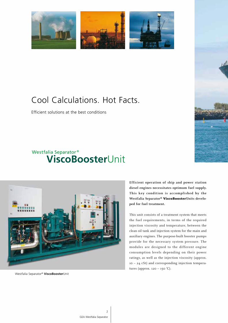
Efficient operation of ship and power station
diesel engines necessitates optimum fuel supply.
This key condition is accomplished by the
Westfalia Separator® ViscoBoosterUnits develo-
ped for fuel treatment.
This unit consists of a treatment system that meets
the fuel requirements, in terms of the required
injection viscosity and temperature, between the
clean oil tank and injection system for the main and
auxiliary engines. The purpose-built booster pumps
provide for the necessary system pressure. The
modules are designed to the different engine
con sumption levels depending on their power
ratings, as well as the injection viscosity (approx.
10 – 24 cSt) and corres ponding injection tempera-
tures (approx. 120 – 150 °C).
Westfalia Separator® ViscoBoosterUnit
2
GEA Westfalia Separator

Fulfills all requirements Depending on the engine manufacturer, different
variants are required for the inte gration of
Westfalia Separator® ViscoBoosterUnits.
GEA Westfalia Separator has res pon ded by offering
a variety of system solutions. Whether with or
without stand-by function for feeder pumps,
booster pumps and heavy fuel oil preheaters, or
for one or more engines – you will always find a
solution that meets your needs and expectations.
Naturally, all systems are compact, lightweight,
reliable, easy to install and simple to maintain
with all main components operating at optimum
performance.
Approved by all major classification societies
3
GEA Westfalia Separator
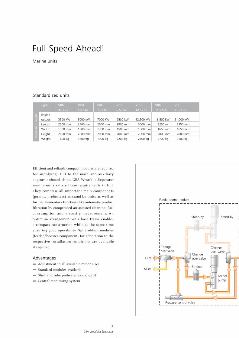
Full Speed Ahead!Marine units
Efficient and reliable compact modules are required
for supplying HFO to the main and auxiliary
engines onboard ships. GEA Westfalia Separator
marine units satisfy these requirements in full.
They comprise all important main components
(pumps, preheaters) as stand-by units as well as
further elementary functions like automatic product
filtration by compressed air-assisted cleaning, fuel
consumption and viscosity measurement. An
optimum arrangement on a base frame enables
a compact construction while at the same time
ensuring good operability. Split add-on modules
(feeder / booster component) for adaptation to the
respective installation conditions are available
if required.
Advantages Adjustment to all available motor sizes
Standard modules available
Shell and tube preheater as standard
Central monitoring system
Pressure control valve
Standardized units
Type VBU VBU VBU VBU VBU VBU VBU
3.5 / 25 5.0 / 32 7.0 / 40 9.5 / 50 12.5 / 50 16.5 / 65 21.0 / 65
Engine
output 3500 kW 5000 kW 7000 kW 9500 kW 12,500 kW 16,500 kW 21,000 kW
Length 2500 mm 2500 mm 2600 mm 2800 mm 3000 mm 3250 mm 3350 mm
Width 1300 mm 1300 mm 1300 mm 1500 mm 1500 mm 1650 mm 1650 mm
Height 2000 mm 2000 mm 2000 mm 2000 mm 2000 mm 2000 mm 2000 mm
Weight 1800 kg 1800 kg 1900 kg 2200 kg 2400 kg 2700 kg 3100 kgDim
ensio
ns &
Wei
ght
4
GEA Westfalia Separator
HFO
MDO
Changeover valve
Feeder pump module
Changeover valve
Strainer
Stand-by
Feeder pump
Changeover valve
Stand-by
Optimally harmonized modules guarantee reliable functionality
Stand-by
Stand-by
Steam trap
Booster pump
Regulating valve
Steam or thermal oil
Preheater
Condensate or thermal oil
Viscosity sensor
Mixing / Degassing tank
Flow meter
Fuel to engine
5
GEA Westfalia Separator
Fuel to day tank
Fuel from engine
Automaticbackflushing filter
Degassing valve
Feeder pump

6
GEA Westfalia Separator
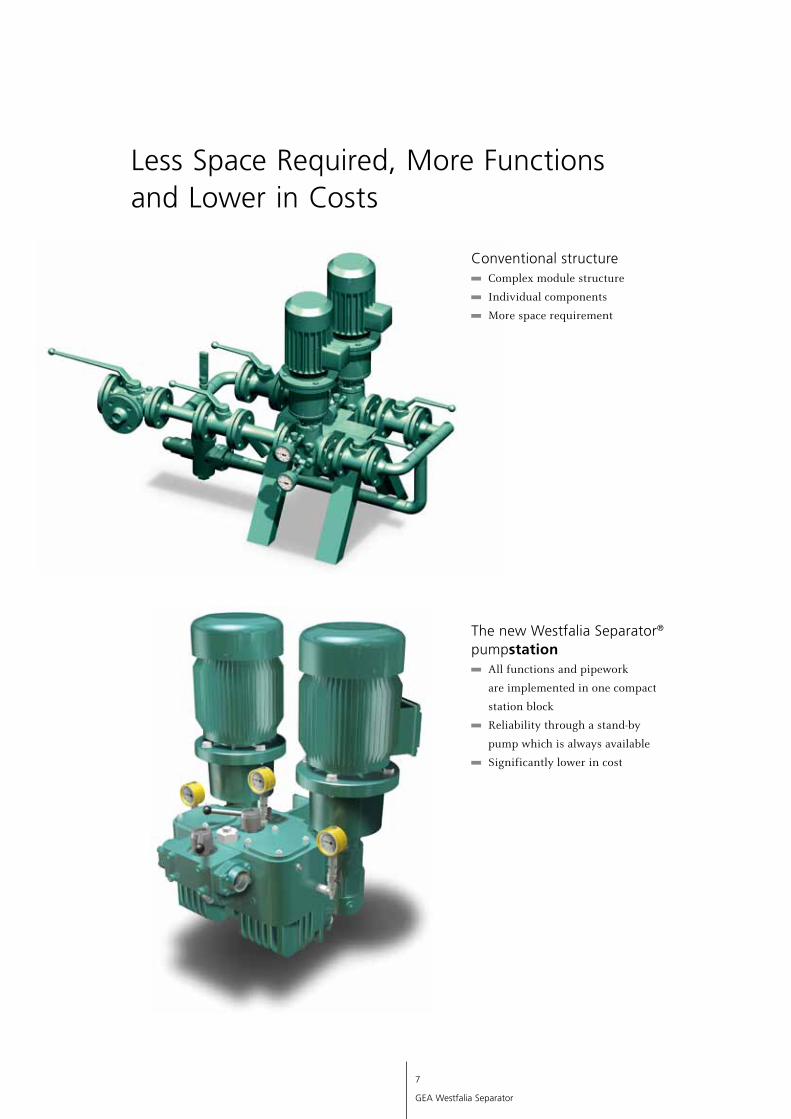
Westfalia Separator® pumpstation was developed
in cooperation with a leading pump manufacturer.
The completely new design of these stations allows
GEA Westfalia Separator to offer the most compact
booster modules and improve our position as
market leader in quality.
More functions – less space requirement. The modular
stations incorporate multiple useful functions for all
applications with two pumps. Compared to single
components you save up to 50 percent space.
Double stations are used, if a second standby pump
is required for safety. Westfalia Separator® pumpstation
has been designed to be highly modular and with
many useful options.
Your advantages More functions
More safety with two pumps
50 percent less space requirement
Simple installation
Available with magnetic coupling
7
GEA Westfalia Separator
Less Space Required, More Functions and Lower in Costs
The new Westfalia Separator® pumpstation
All functions and pipework
are implemented in one compact
station block
Reliability through a stand-by
pump which is always available
Significantly lower in cost
Conventional structure Complex module structure
Individual components
More space requirement
8
GEA Westfalia Separator
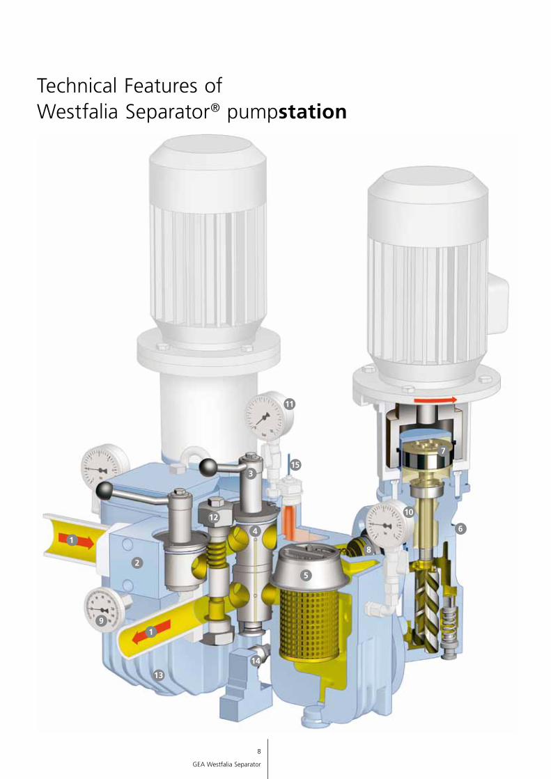
Technical Features of Westfalia Separator® pumpstation
11
1
1
2
9
14
13
12
4
5
315
7
10
6
8
9
GEA Westfalia Separator
Technical Features of Westfalia Separator® pumpstation
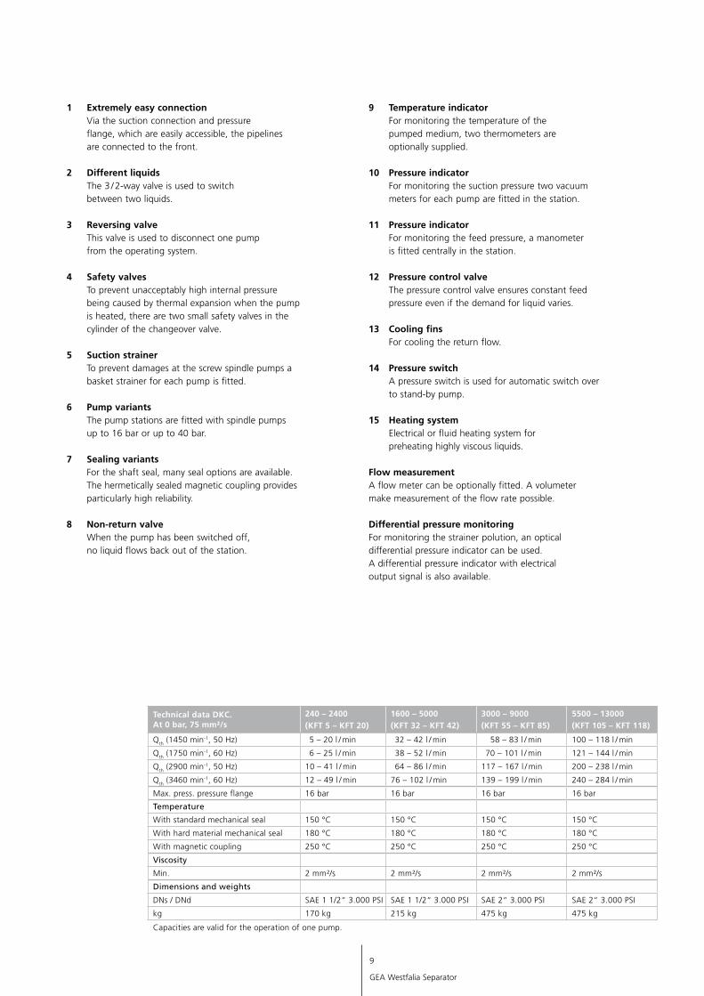
Technical data DKC.At 0 bar, 75 mm²/s
240 – 2400(KFT 5 – KFT 20)
1600 – 5000(KFT 32 – KFT 42)
3000 – 9000(KFT 55 – KFT 85)
5500 – 13000(KFT 105 – KFT 118)
Qth (1450 min-1, 50 Hz) 5 – 20 l / min 32 – 42 l / min 58 – 83 l / min 100 – 118 l / min
Qth (1750 min-1, 60 Hz) 6 – 25 l / min 38 – 52 l / min 70 – 101 l / min 121 – 144 l / min
Qth (2900 min-1, 50 Hz) 10 – 41 l / min 64 – 86 l / min 117 – 167 l / min 200 – 238 l / min
Qth (3460 min-1, 60 Hz) 12 – 49 l / min 76 – 102 l / min 139 – 199 l / min 240 – 284 l / min
Max. press. pressure flange 16 bar 16 bar 16 bar 16 bar
Temperature
With standard mechanical seal 150 °C 150 °C 150 °C 150 °C
With hard material mechanical seal ata 180 °C 180 °C 180 °C 180 °C
With magnetic coupling 250 °C 250 °C 250 °C 250 °C
Viscosity
Min. 2 mm²/s 2 mm²/s 2 mm²/s 2 mm²/s
Dimensions and weights
DNs / DNd SAE 1 1/2“ 3.000 PSI SAE 1 1/2“ 3.000 PSI SAE 2“ 3.000 PSI SAE 2“ 3.000 PSI
kg 170 kg 215 kg 475 kg 475 kg
Capacities are valid for the operation of one pump.
1 Extremely easy connection Via the suction connection and pressure flange, which are easily accessible, the pipelines are connected to the front.
2 Different liquidsThe 3 / 2-way valve is used to switch between two liquids.
3 Reversing valveThis valve is used to disconnect one pump from the operating system.
4 Safety valvesTo prevent unacceptably high internal pressure being caused by thermal expansion when the pump is heated, there are two small safety valves in the cylinder of the changeover valve.
5 Suction strainerTo prevent damages at the screw spindle pumps a basket strainer for each pump is fitted.
6 Pump variantsThe pump stations are fitted with spindle pumps up to 16 bar or up to 40 bar.
7 Sealing variantsFor the shaft seal, many seal options are available. The hermetically sealed magnetic coupling provides particularly high reliability.
8 Non-return valveWhen the pump has been switched off, no liquid flows back out of the station.
9 Temperature indicatorFor monitoring the temperature of the pumped medium, two thermometers are optionally supplied.
10 Pressure indicatorFor monitoring the suction pressure two vacuum meters for each pump are fitted in the station.
11 Pressure indicatorFor monitoring the feed pressure, a manometer is fitted centrally in the station.
12 Pressure control valveThe pressure control valve ensures constant feed pressure even if the demand for liquid varies.
13 Cooling finsFor cooling the return flow.
14 Pressure switchA pressure switch is used for automatic switch over to stand-by pump.
15 Heating systemElectrical or fluid heating system for preheating highly viscous liquids.
Flow measurementA flow meter can be optionally fitted. A volumeter make measurement of the flow rate possible.
Differential pressure monitoringFor monitoring the strainer polution, an optical differential pressure indicator can be used. A differential pressure indicator with electrical output signal is also available.
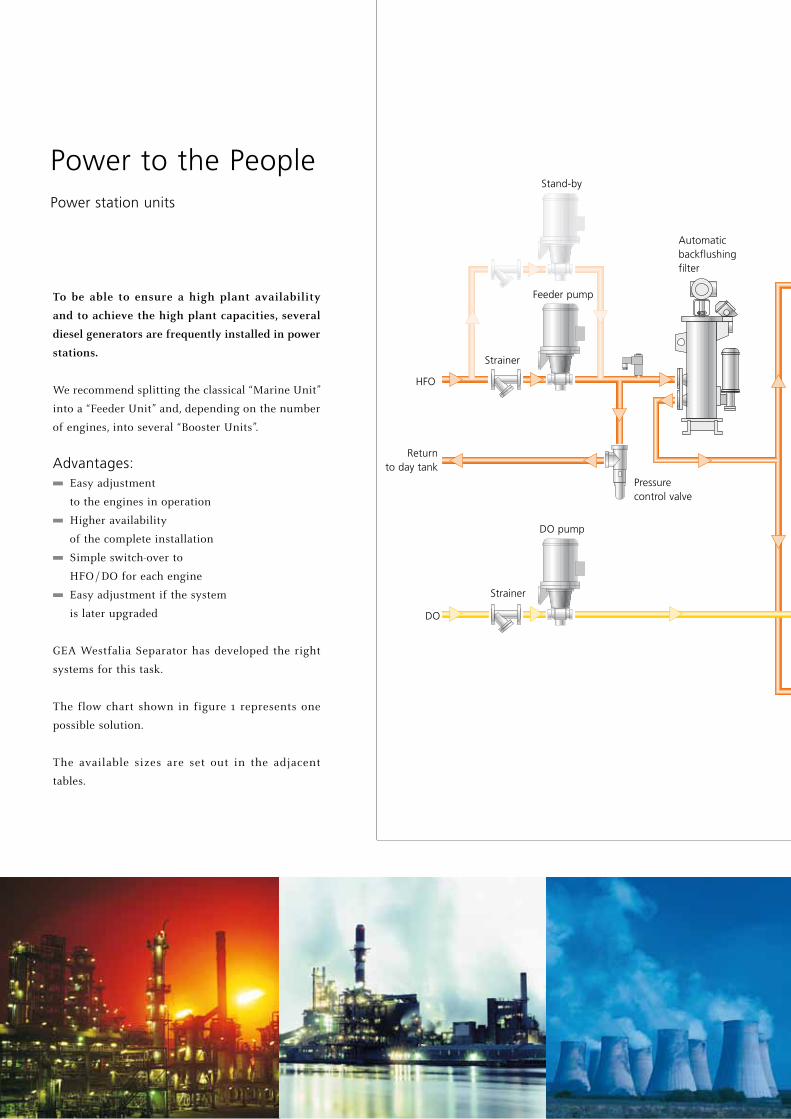
To be able to ensure a high plant availability
and to achieve the high plant capacities, several
diesel generators are frequently installed in power
stations.
We recommend splitting the classical “Marine Unit”
into a “Feeder Unit” and, depending on the number
of engines, into several “Booster Units”.
Advantages: Easy adjustment
to the engines in operation
Higher availability
of the complete insta lla tion
Simple switch-over to
HFO / DO for each engine
Easy adjustment if the system
is later upgraded
GEA Westfalia Separator has de ve loped the right
systems for this task.
The flow chart shown in figure 1 represents one
possible solution.
The available sizes are set out in the adjacent
tables.
Power to the PeoplePower station units
HFO
DO
Return to day tank
Pressure control valve
Strainer
Strainer
Stand-by
Feeder pump
DO pump
Automaticbackflushing filter
Fuel from engine

Condensate or thermal oil
Steam trap
Booster pump
Booster pump
Fuel to engine
Viscosity sensor
Flowmeter
Fuel to day tank
Fuel from
engine
HFO
DO
HFO
DO
Stand-by / Option
Stand-by / Option
Stand-by / Option
Stand-by / Option
Steam trap
Regulatingvalve
Steam or thermal oil
Preheater
Preheater
Degassing valve
Mixing / Degassing tank
Flowmeter
The split into feeder and booster unit guarantees high
capacities in power stationsFeeder Unit:
Sizes Flow rate
10,000 kW 3.5 m3 / h
20,000 kW 7.0 m3 / h
40,000 kW 14.0 m3 / h
60,000 kW 21.0 m3 / h
80,000 kW 28.0 m3 / h
100,000 kW 35.0 m3 / h
Booster Unit(s):
Sizes Flow rate
3500 – 5000 kW 2.2 to 3.2 m3 / h
5000 – 7000 kW 3.2 to 4.7 m3 / h
7000 – 9500 kW 4.7 to 5.6 m3 / h
9500 – 12,500 kW 5.6 to 7.9 m3 / h
12,500 – 16,500 kW 7.9 to 10.4 m3 / h
16,500 – 21,000 kW 10.4 to 13.3 m3 / h
11
GEA Westfalia Separator
Condensate or thermal oil
Fuel to day tank
Fuel from engine
Degassing valve
Mixing / Degassing tank
Regulatingvalve
Steam or thermal oil
Fuel to engine
Viscosity sensor
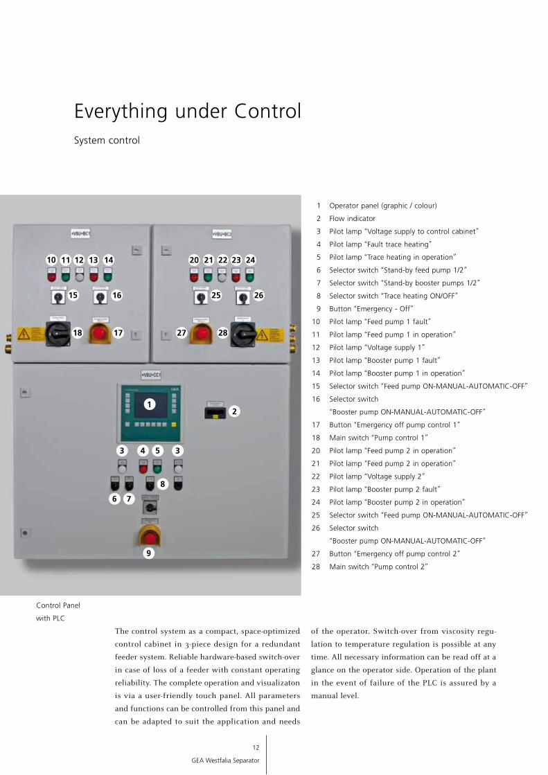
Everything under ControlSystem control
The control system as a compact, space-optimized
control cabinet in 3-piece design for a redundant
feeder system. Reliable hardware-based switch-over
in case of loss of a feeder with constant operating
reliability. The complete operation and visualizaton
is via a user-friendly touch panel. All parameters
and functions can be controlled from this panel and
can be adapted to suit the application and needs
of the operator. Switch-over from viscosity regu-
lation to temperature regulation is possible at any
time. All necessary information can be read off at a
glance on the operator side. Operation of the plant
in the event of failure of the PLC is assured by a
manual level.
1 Operator panel (graphic / colour)
2 Flow indicator
3 Pilot lamp “Voltage supply to control cabinet”
4 Pilot lamp “Fault trace heating”
5 Pilot lamp “Trace heating in operation”
6 Selector switch “Stand-by feed pump 1/2”
7 Selector switch “Stand-by booster pumps 1/2”
8 Selector switch “Trace heating ON/OFF”
9 Button “Emergency - Off”
10 Pilot lamp “Feed pump 1 fault”
11 Pilot lamp “Feed pump 1 in operation”
12 Pilot lamp “Voltage supply 1”
13 Pilot lamp “Booster pump 1 fault”
14 Pilot lamp “Booster pump 1 in operation”
15 Selector switch “Feed pump ON-MANUAL-AUTOMATIC-OFF”
16 Selector switch
“Booster pump ON-MANUAL-AUTOMATIC-OFF”
17 Button “Emergency off pump control 1”
18 Main switch “Pump control 1”
20 Pilot lamp “Feed pump 2 in operation”
21 Pilot lamp “Feed pump 2 in operation”
22 Pilot lamp “Voltage supply 2”
23 Pilot lamp “Booster pump 2 fault”
24 Pilot lamp “Booster pump 2 in operation”
25 Selector switch “Feed pump ON-MANUAL-AUTOMATIC-OFF”
26 Selector switch
“Booster pump ON-MANUAL-AUTOMATIC-OFF”
27 Button “Emergency off pump control 2”
28 Main switch “Pump control 2”
Control Panel
with PLC
1
10 11
2
6
12
GEA Westfalia Separator
12 13 20 21 22 23 2414
15 16 25 26
7
8
3 4 5 3
9
1718 27 28

1 Operator panel (graphic / colour)
2 Flow indicator
3 Pilot lamp “Voltage supply to control cabinet”
4 Pilot lamp “Fault trace heating”
5 Pilot lamp “Trace heating in operation”
6 Selector switch “Stand-by feed pump 1/2”
7 Selector switch “Stand-by booster pumps 1/2”
8 Selector switch “Trace heating ON/OFF”
9 Button “Emergency - Off”
10 Pilot lamp “Feed pump 1 fault”
11 Pilot lamp “Feed pump 1 in operation”
12 Pilot lamp “Voltage supply 1”
13 Pilot lamp “Booster pump 1 fault”
14 Pilot lamp “Booster pump 1 in operation”
15 Selector switch “Feed pump ON-MANUAL-AUTOMATIC-OFF”
16 Selector switch
“Booster pump ON-MANUAL-AUTOMATIC-OFF”
17 Button “Emergency off pump control 1”
18 Main switch “Pump control 1”
20 Pilot lamp “Feed pump 2 in operation”
21 Pilot lamp “Feed pump 2 in operation”
22 Pilot lamp “Voltage supply 2”
23 Pilot lamp “Booster pump 2 fault”
24 Pilot lamp “Booster pump 2 in operation”
25 Selector switch “Feed pump ON-MANUAL-AUTOMATIC-OFF”
26 Selector switch
“Booster pump ON-MANUAL-AUTOMATIC-OFF”
27 Button “Emergency off pump control 2”
28 Main switch “Pump control 2”
A focus on the essentials Compact, robust design
Good operability
Automatic viscosity control
Automated control system via common
control cabinet with redundant power supply
Automatic, compressed-air controlled
filter system for particle separation
Low weight
Easy installation
Low maintenance costs
VBU
13
GEA Westfalia Separator
14
GEA Westfalia Separator
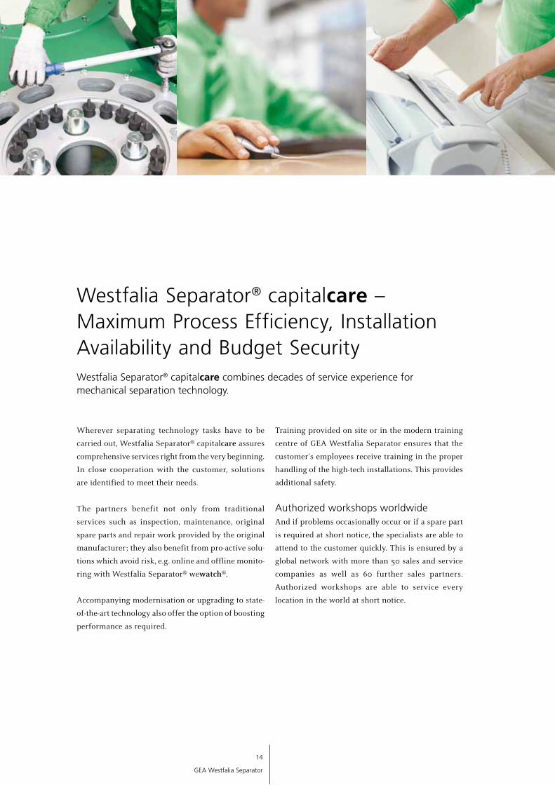
Wherever separating technology tasks have to be
carried out, Westfalia Separator® capitalcare assures
comprehensive services right from the very beginning.
In close cooperation with the customer, solutions
are identified to meet their needs.
The partners benefit not only from traditional
services such as inspection, maintenance, original
spare parts and repair work provided by the original
manufacturer; they also benefit from pro-active solu-
tions which avoid risk, e.g. online and offline monito-
ring with Westfalia Separator® wewatch®.
Accompanying modernisation or upgrading to state-
of-the-art technology also offer the option of boosting
performance as required.
Training provided on site or in the modern training
centre of GEA Westfalia Separator ensures that the
customer‘s employees receive training in the proper
handling of the high-tech installations. This provides
additional safety.
Authorized workshops worldwideAnd if problems occasionally occur or if a spare part
is required at short notice, the specialists are able to
attend to the customer quickly. This is ensured by a
global network with more than 50 sales and service
companies as well as 60 further sales partners.
Authorized workshops are able to service every
location in the world at short notice.
Westfalia Separator® capitalcare combines decades of service experience for mechanical separation technology.
Westfalia Separator® capitalcare – Maximum Process Efficiency, Installation Availability and Budget Security

15
GEA Westfalia Separator
Maximum availability
Permanent efficiency
Absolute budget reliability
In addition to traditional services such as maintenance or repair, Westfalia Separator® capitalcare also provides solutions which avoid risk and with which the installation availability can be pro-actively assured.
Westfalia Separator® capitalcare accordingly makes
for maximum process efficiency and installation
availability as well as budget security. And these
benefits are provided throughout the entire life cycle
of the entire installation.
Service from the original manufacturer: Service engineers quickly on site
Extensive service network
Risk avoided by service provided
by the original manufacturer
Pro-active solutions which avoid risk
Upgrading to boost performance
Staff training

The information contained in this brochure merely serves as a non-binding description of our productsand is without guarantee.
Binding information, in particular relating to capacity data and suitability for specific applications, can only beprovided within the framework of concrete inquiries. Westfalia®, Westfalia Separator ® and wewatch®
are registered trademarks of GEA Westfalia Separator GmbH. Printed on chlorine-free bleached paperwww.kabutz.de 9997-0787-030/0809 EN Printed in Germany Subject to modification
Beverage Technology
Dairy Technology
Renewable Resources
Chemical / Pharmaceutical Technology
Marine
Energy
Oil, Gas & Industrial Fluids
Fluids & Water
Engineering
Second Hand Machinery
Original Manufacturer Service
Werner-Habig-Str. 1 · 59302 Oelde (Germany) Phone +49 2522 77-0 · Fax +49 2522 77-1778 [email protected] · www.westfalia-separator.com
GEA Mechanical Equipment
GEA Westfalia Separator