west coast regional carbon sequestration partnership … · 2018-01-12 · west coast regional...
TRANSCRIPT

West Coast Regional Carbon Sequestration Partnership (WESTCARB)
Assessment of Natural Gas Combined Cycle Plants for Carbon Dioxide Capture and Storage in Gas-Dominated Electricity Market –
Request for Proposals RFP# 500-10-502
PRELIMINARY ASSESSMENT PAPER
Attachment 20

TABLE OF CONTENTS Page
Summary of Known CO2 Capture Technologies ........................................................ 1
Summary for Plants Planned or Under Construction ............................................... 5
Design and Site Characteristics for Operational Plants ........................................... 8
Generation/Emissions Data for Operational Plants ................................................ 10
California Map of NGCC Plants and Potential CO2 Storage Locations .................. 11
Attachment 20
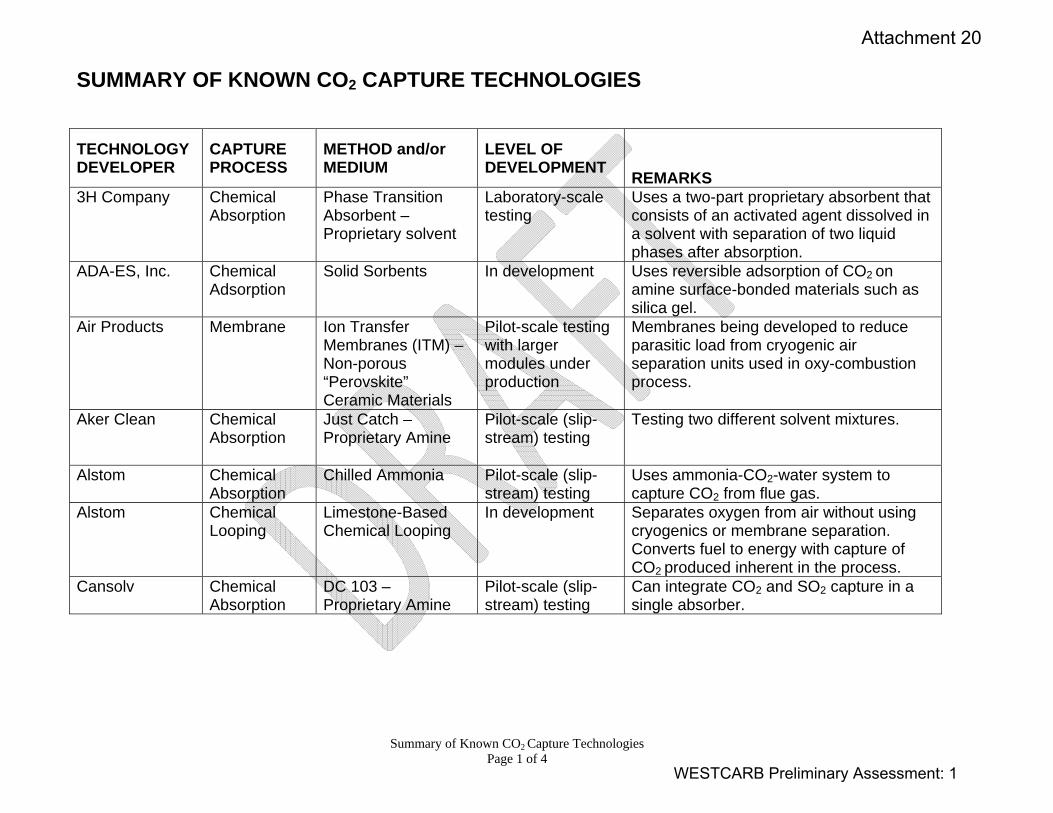
Summary of Known CO2 Capture Technologies Page 1 of 4
SUMMARY OF KNOWN CO2 CAPTURE TECHNOLOGIES
TECHNOLOGY DEVELOPER
CAPTURE PROCESS
METHOD and/or MEDIUM
LEVEL OF DEVELOPMENT REMARKS
3H Company Chemical Absorption
Phase Transition Absorbent – Proprietary solvent
Laboratory-scale testing
Uses a two-part proprietary absorbent that consists of an activated agent dissolved in a solvent with separation of two liquid phases after absorption.
ADA-ES, Inc. Chemical Adsorption
Solid Sorbents In development Uses reversible adsorption of CO2 on amine surface-bonded materials such as silica gel.
Air Products Membrane Ion Transfer Membranes (ITM) – Non-porous “Perovskite” Ceramic Materials
Pilot-scale testing with larger modules under production
Membranes being developed to reduce parasitic load from cryogenic air separation units used in oxy-combustion process.
Aker Clean Chemical Absorption
Just Catch – Proprietary Amine
Pilot-scale (slip-stream) testing
Testing two different solvent mixtures.
Alstom Chemical Absorption
Chilled Ammonia Pilot-scale (slip-stream) testing
Uses ammonia-CO2-water system to capture CO2 from flue gas.
Alstom Chemical Looping
Limestone-Based Chemical Looping
In development Separates oxygen from air without using cryogenics or membrane separation. Converts fuel to energy with capture of CO2 produced inherent in the process.
Cansolv Chemical Absorption
DC 103 – Proprietary Amine
Pilot-scale (slip-stream) testing
Can integrate CO2 and SO2 capture in a single absorber.
WESTCARB Preliminary Assessment: 1
Attachment 20
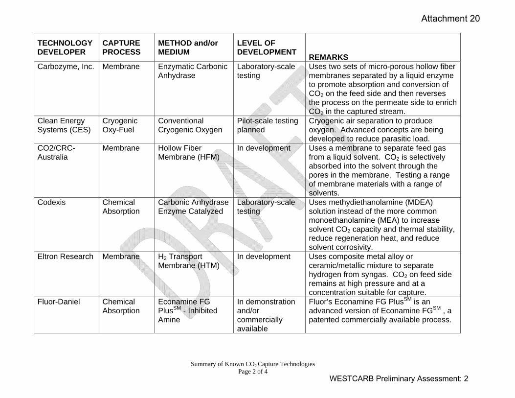
Summary of Known CO2 Capture Technologies Page 2 of 4
TECHNOLOGY DEVELOPER
CAPTURE PROCESS
METHOD and/or MEDIUM
LEVEL OF DEVELOPMENT REMARKS
Carbozyme, Inc. Membrane Enzymatic Carbonic Anhydrase
Laboratory-scale testing
Uses two sets of micro-porous hollow fiber membranes separated by a liquid enzyme to promote absorption and conversion of CO2 on the feed side and then reverses the process on the permeate side to enrich CO2 in the captured stream.
Clean Energy Systems (CES)
Cryogenic Oxy-Fuel
Conventional Cryogenic Oxygen
Pilot-scale testing planned
Cryogenic air separation to produce oxygen. Advanced concepts are being developed to reduce parasitic load.
CO2/CRC- Australia
Membrane Hollow Fiber Membrane (HFM)
In development Uses a membrane to separate feed gas from a liquid solvent. CO2 is selectively absorbed into the solvent through the pores in the membrane. Testing a range of membrane materials with a range of solvents.
Codexis Chemical Absorption
Carbonic Anhydrase Enzyme Catalyzed
Laboratory-scale testing
Uses methydiethanolamine (MDEA) solution instead of the more common monoethanolamine (MEA) to increase solvent CO2 capacity and thermal stability, reduce regeneration heat, and reduce solvent corrosivity.
Eltron Research Membrane H2 Transport Membrane (HTM)
In development Uses composite metal alloy or ceramic/metallic mixture to separate hydrogen from syngas. CO2 on feed side remains at high pressure and at a concentration suitable for capture.
Fluor-Daniel Chemical Absorption
Econamine FG PlusSM - Inhibited Amine
In demonstration and/or commercially available
Fluor’s Econamine FG PlusSM is an advanced version of Econamine FGSM , a patented commercially available process.
WESTCARB Preliminary Assessment: 2
Attachment 20
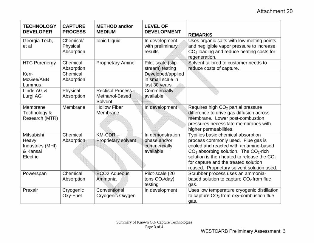
Summary of Known CO2 Capture Technologies Page 3 of 4
TECHNOLOGY DEVELOPER
CAPTURE PROCESS
METHOD and/or MEDIUM
LEVEL OF DEVELOPMENT REMARKS
Georgia Tech, et al
Chemical/ Physical Absorption
Ionic Liquid In development with preliminary results
Uses organic salts with low melting points and negligible vapor pressure to increase CO2 loading and reduce heating costs for regeneration.
HTC Purenergy Chemical Absorption
Proprietary Amine Pilot-scale (slip-stream) testing
Solvent tailored to customer needs to reduce costs of capture.
Kerr-McGee/ABB Lummus
Chemical Absorption
Developed/applied in small scale in last 30 years.
Linde AG & Lurgi AG
Physical Absorption
Rectisol Process - Methanol-Based Solvent
Commercially available
Membrane Technology & Research (MTR)
Membrane Hollow Fiber Membrane
In development Requires high CO2 partial pressure difference to drive gas diffusion across membrane. Lower post-combustion pressures necessitate membranes with higher permeabilities.
Mitsubishi Heavy Industries (MHI) & Kansai Electric
Chemical Absorption
KM-CDR – Proprietary solvent
In demonstration phase and/or commercially available
Typifies basic chemical absorption process commonly used. Flue gas is cooled and reacted with an amine-based CO2 absorbing solution. The CO2-rich solution is then heated to release the CO2 for capture and the treated solution reused. Proprietary solvent solution used.
Powerspan Chemical Absorption
ECO2 Aqueous Ammonia
Pilot-scale (20 tons CO2/day) testing
Scrubber process uses an ammonia-based solution to capture CO2 from flue gas.
Praxair Cryogenic Oxy-Fuel
Conventional Cryogenic Oxygen
In development Uses low temperature cryogenic distillation to capture CO2 from oxy-combustion flue gas.
WESTCARB Preliminary Assessment: 3
Attachment 20
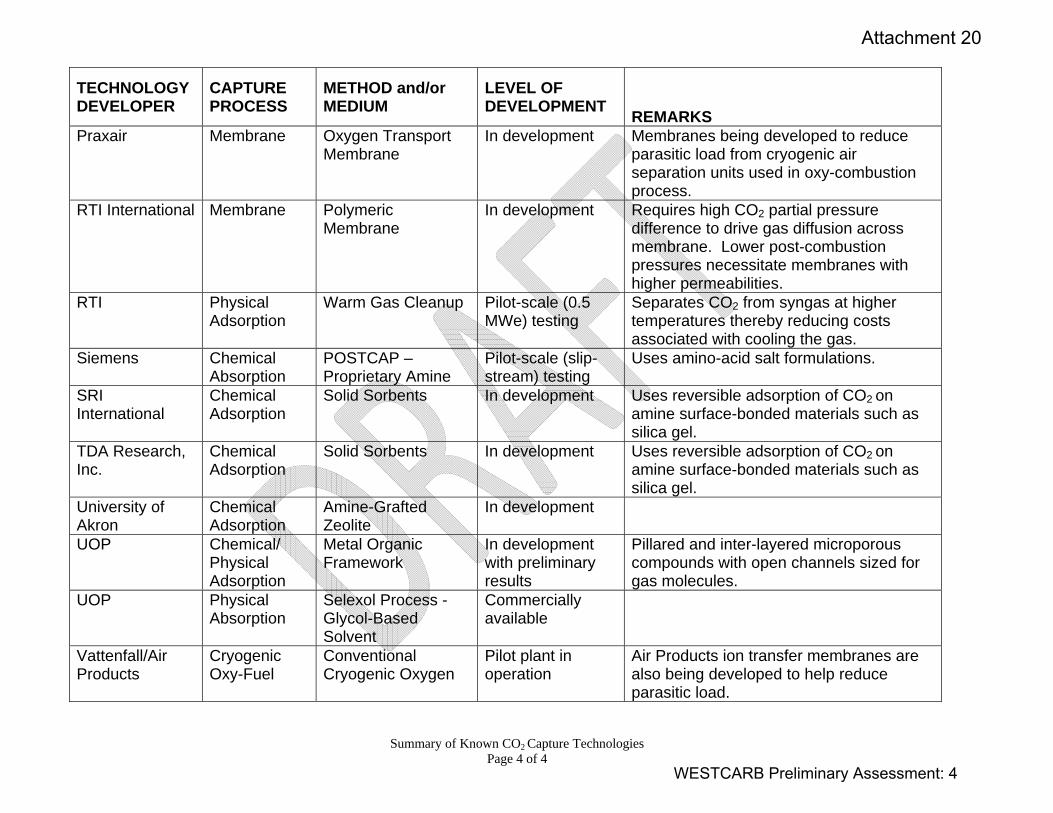
Summary of Known CO2 Capture Technologies Page 4 of 4
TECHNOLOGY DEVELOPER
CAPTURE PROCESS
METHOD and/or MEDIUM
LEVEL OF DEVELOPMENT REMARKS
Praxair Membrane Oxygen Transport Membrane
In development Membranes being developed to reduce parasitic load from cryogenic air separation units used in oxy-combustion process.
RTI International Membrane Polymeric Membrane
In development Requires high CO2 partial pressure difference to drive gas diffusion across membrane. Lower post-combustion pressures necessitate membranes with higher permeabilities.
RTI Physical Adsorption
Warm Gas Cleanup Pilot-scale (0.5 MWe) testing
Separates CO2 from syngas at higher temperatures thereby reducing costs associated with cooling the gas.
Siemens Chemical Absorption
POSTCAP – Proprietary Amine
Pilot-scale (slip-stream) testing
Uses amino-acid salt formulations.
SRI International
Chemical Adsorption
Solid Sorbents In development Uses reversible adsorption of CO2 on amine surface-bonded materials such as silica gel.
TDA Research, Inc.
Chemical Adsorption
Solid Sorbents In development Uses reversible adsorption of CO2 on amine surface-bonded materials such as silica gel.
University of Akron
Chemical Adsorption
Amine-Grafted Zeolite
In development
UOP Chemical/ Physical Adsorption
Metal Organic Framework
In development with preliminary results
Pillared and inter-layered microporous compounds with open channels sized for gas molecules.
UOP Physical Absorption
Selexol Process - Glycol-Based Solvent
Commercially available
Vattenfall/Air Products
Cryogenic Oxy-Fuel
Conventional Cryogenic Oxygen
Pilot plant in operation
Air Products ion transfer membranes are also being developed to help reduce parasitic load.
WESTCARB Preliminary Assessment: 4
Attachment 20
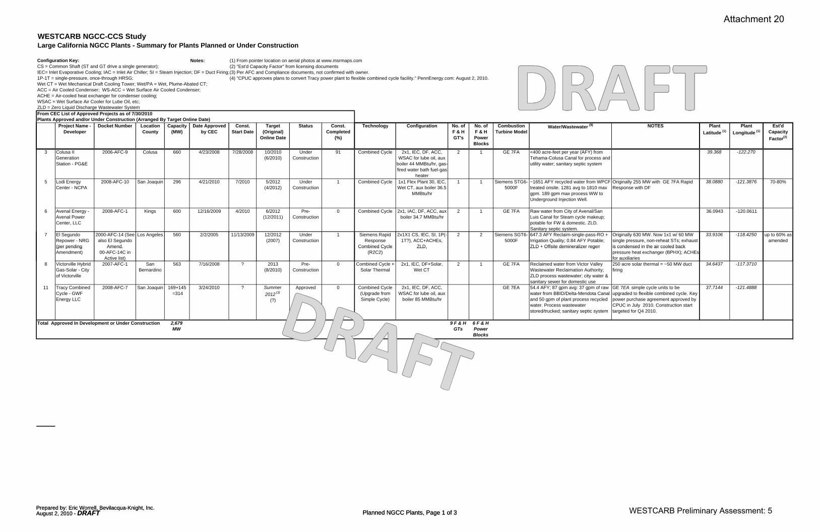
WESTCARB NGCC-CCS StudyLarge California NGCC Plants - Summary for Plants Planned or Under Construction
Configuration Key: Notes: (1) From pointer location on aerial photos at www.msrmaps.comCS = Common Shaft (ST and GT drive a single generator); (2) "Est'd Capacity Factor" from licensing documentsIEC= Inlet Evaporative Cooling; IAC = Inlet Air Chiller; SI = Steam Injection; DF = Duct Firing;(3) Per AFC and Compliance documents, not confirmed with owner.1P-1T = single-pressure, once-through HRSG; (4) "CPUC approves plans to convert Tracy power plant to flexible combined cycle facility." PennEnergy.com: August 2, 2010.Wet CT = Wet Mechanical Draft Cooling Tower; Wet/PA = Wet, Plume-Abated CT; ACC = Air Cooled Condenser; WS-ACC = Wet Surface Air Cooled Condenser; ACHE = Air-cooled heat exchanger for condenser cooling;WSAC = Wet Surface Air Cooler for Lube Oil, etc; ZLD = Zero Liquid Discharge Wastewater SystemFrom CEC List of Approved Projects as of 7/30/2010Plants Approved and/or Under Construction (Arranged By Target Online Date)
P j t N D k t N b L ti C it D t A d C t T t St t C t T h l C fi ti N f N f C b ti (3) NOTES Pl t Pl t E t'd
Prepared by: Eric Worrell, Bevilacqua-Knight, Inc.August 2, 2010 - DRAFT Planned NGCC Plants, Page 1 of 3
Project Name - Developer
Docket Number Location County
Capacity(MW)
Date Approved by CEC
Const. Start Date
Target (Original)
Online Date
Status Const. Completed
(%)
Technology Configuration No. ofF & HGT's
No. ofF & HPowerBlocks
Combustion Turbine Model
Water/Wastewater (3) NOTES Plant Latitude (1)
Plant Longitude (1)
Est'd Capacity Factor(2)
3 Colusa II Generation Station - PG&E
2006-AFC-9 Colusa 660 4/23/2008 7/28/2008 10/2010 (6/2010)
Under Construction
91 Combined Cycle 2x1, IEC, DF, ACC, WSAC for lube oil, aux
boiler 44 MMBtu/hr, gas-fired water bath fuel-gas
heater
2 1 GE 7FA <400 acre-feet per year (AFY) from Tehama-Colusa Canal for process and utility water; sanitary septic system
39.368 -122.270
5 Lodi Energy Center - NCPA
2008-AFC-10 San Joaquin 296 4/21/2010 7/2010 5/2012 (4/2012)
UnderConstruction
1 Combined Cycle 1x1 Flex Plant 30, IEC, Wet CT, aux boiler 36.5
MMBtu/hr
1 1 Siemens STG6-5000F
~1651 AFY recycled water from WPCF treated onsite. 1281 avg to 1810 max gpm. 189 gpm max process WW to Underground Injection Well.
Originally 255 MW with GE 7FA Rapid Response with DF
38.0880 -121.3876 70-80%
6 Avenal Energy - Avenal Power Center, LLC
2008-AFC-1 Kings 600 12/16/2009 4/2010 6/2012(12/2011)
Pre-Construction
0 Combined Cycle 2x1, IAC, DF, ACC, aux boiler 34.7 MMBtu/hr
2 1 GE 7FA Raw water from City of Avenal/San Luis Canal for Steam cycle makeup; potable for FW & domestic. ZLD. Sanitary septic system.
36.0943 -120.0611
7 El Segundo Repower - NRG (per pending
2000-AFC-14 (See also El Segundo
Amend.
Los Angeles 560 2/2/2005 11/13/2009 12/2012 (2007)
Under Construction
1 Siemens Rapid Response
Combined Cycle
2x1X1 CS, IEC, SI, 1P(-1T?), ACC+ACHEs,
ZLD,
2 2 Siemens SGT6-5000F
647.3 AFY Reclaim-single-pass-RO + Irrigation Quality; 0.84 AFY Potable; ZLD + Offsite demineralizer regen
Originally 630 MW. Now 1x1 w/ 60 MW single pressure, non-reheat STs; exhaust is condensed in the air cooled back
33.9106 -118.4250 up to 60% as amended
(per pending Amendment)
Amend.00-AFC-14C in
Active list)
Combined Cycle (R2C2)
ZLD, ZLD Offsite demineralizer regen is condensed in the air cooled back pressure heat exchanger (BPHX); ACHEs for auxiliaries
8 Victorville Hybrid Gas-Solar - City of Victorville
2007-AFC-1 San Bernardino
563 7/16/2008 ? 2013(8/2010)
Pre-Construction
0 Combined Cycle + Solar Thermal
2x1, IEC, DF+Solar, Wet CT
2 1 GE 7FA Reclaimed water from Victor Valley Wastewater Reclaimation Authority; ZLD process wastewater; city water & sanitary sewer for domestic use
250 acre solar thermal = ~50 MW duct firing
34.6437 -117.3710
11 Tracy Combined Cycle - GWF Energy LLC
2008-AFC-7 San Joaquin 169+145 =314
3/24/2010 ? Summer 2012 (3)
(?)
Approved 0 Combined Cycle (Upgrade from Simple Cycle)
2x1, IEC, DF, ACC, WSAC for lube oil, aux
boiler 85 MMBtu/hr
GE 7EA 54.4 AFY; 87 gpm avg: 37 gpm of raw water from BBID/Delta-Mendota Canal and 50 gpm of plant process recycled water. Process wastewater stored/trucked; sanitary septic system
GE 7EA simple cycle units to be upgraded to flexible combined cycle. Key power purchase agreement approved by CPUC in July 2010. Construction start targeted for Q4 2010.
37.7144 -121.4888
Total Approved In Development or Under Construction 2,679 MW
9 F & H GTs
6 F & H Power Blocks
Prepared by: Eric Worrell, Bevilacqua-Knight, Inc.August 2, 2010 - DRAFT Planned NGCC Plants, Page 1 of 3 WESTCARB Preliminary Assessment: 5
Attachment 20

From CEC List of Approved Projects as of 7/30/2010Projects Approved and On Hold
Project Name - Developer
Docket Number Location County
Capacity(MW)
Date Approved by CEC
Const. Start Date
Target (Original)
Online Date
Status Const. Completed
(%)
Technology Configuration No. ofF & HGT's
No. ofF & HPowerBlocks
Combustion Turbine Model
Water/Wastewater (3) NOTES Plant Latitude (1)
Plant Longitude (1)
Est'd Capacity Factor(2)
1 Russell City - Calpine & GE
2001-AFC-07 Alameda 60010/03/2007 On Hold
On Hold (12/2004) On Hold -
Combined Cycle 2x1, DF, Wet CT 2 1 Siemens W501FD
Onsite treatment of secondary effluent for Recycled Water, ZLD; city water for domestic/firewater
37.6380 -122.1364
3 Morro Bay - L.S. Power
2000-AFC-12 San Luis Obispo
1,200 8/2/2004 Note: Commission decision not
finalized pending NPDS permit
On Hold On Hold On Hold - Combined Cycle 2 -- 2x1, DF, Once-through CW
4 2 GE 7FA Seawater, subject to flow limits & habitat remediation
Site judged not suitable for ACC; will use once-through seawater and habitat mitigation. Wells for industrial/domestic supply; WW treat on site to outfall or disch to sanitary sewer.
35.3756 -120.8589
4 Tesla - FPL 2001-AFC-21 Alameda 1,120 On Hold On Hold Combined Cycle 2x2x1, IEC, DF, Wet/PA 4 2 GE 7FA ~5100 AFY from CA Aqueduct per 37.7410 -121.5720
Prepared by: Eric Worrell, Bevilacqua-Knight, Inc.August 2, 2010 - DRAFT Planned NGCC Plants, Page 2 of 3
6/16/2004 On Hold (License Expired?) -
y ~5100 AFY from CA Aqueduct per Agreement with Rosedale/Rio Bravo District; ZLD + sanitary septic system
6 Pastoria Simple Cycle Addition - Calpine
2005-AFC-1 Kern 160
12/18/2006 On Hold
On Hold(6/2007)
On Hold
-
Simple Cycle 1xSC, IEC (fogging) GE 7FA Existing PL from CA Aqueduct; source: Wheeler Ridge Maricopa Water Storage District, Kern Water Bank contacts; existing ZLD
Addition to 2x1 + 1x1 config 34.955 -118.846
8 East Altamont - Calpine
2001-AFC-04 Alameda 1,1008/20/2003
8/19/2011 (Deadline extended)
On Hold (7/2005)
On Hold-
Combined Cycle 3x1, IEC, SI, DF, Wet CT, ZLD, aux boiler
3 1 GE 7FB ~4618 AFY surface water from the Byron Bethany Irrigation District (BBID).
1 MW NG fired emergency gen; diesel fire pump
37.8056 -121.5755
11 Blythe II - Caithness
2002-AFC-01, 2009-10-
26_Amendment.pdf
Riverside 569 520
12/14/2005 On Hold
On Hold On Hold
-
Siemens Flex Plant 30 Rapid Start Combined
Cycle
2x1, IAC, DF, Wet CT, Aux Boiler 60 MMBtu/hr
2 1 Siemens SGT6-5000F 3,300 AFY degraded groundwater from
2x3000 gpm well, ZLD with standby evap pond; sanitary septic system; voluntary conservation offset.
CO2e = 1,870,000 – 1,930,000 metric tons/year; 538 MW max output
33.6139 -114.6864
Total Approved -- On Hold 4,700 MW
15 F & H GTs
7 F & H Power Blocks
Prepared by: Eric Worrell, Bevilacqua-Knight, Inc.August 2, 2010 - DRAFT Planned NGCC Plants, Page 2 of 3 WESTCARB Preliminary Assessment: 6
Attachment 20
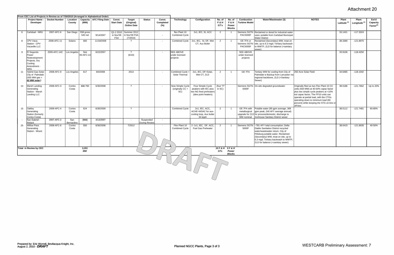
From CEC List of Projects in Review as of 7/30/2010 (Arranged in Alphabetical Order)Project Name -
DeveloperDocket Number Location
CountyCapacity
(MW)AFC Filing Date Const.
Start DateTarget
(Original) Online Date
Status Const. Completed
(%)
Technology Configuration No. ofF & HGT's
No. ofF & HPowerBlocks
Combustion Turbine Model
Water/Wastewater (3) NOTES Plant Latitude (1)
Plant Longitude (1)
Est'd Capacity Factor(2)
6 Carlsbad - NRG 2007-AFC-6 San Diego 558 gross 540 net 9/14/2007
Q1-2 2010 in Nov'09
FSA
Summer 2012 in Nov'09 FSA
(7/2010)-
flex Plant 10 Combined Cycle
2x1, IEC, SI, ACC 2 1 Siemens SGT6-PAC5000F
Reclaimed or desal for industrial water uses; potable from Carlsbad Municipal Water District
33.1431 -117.3324
8 CPV Vaca-Station - CPV Vacaville LLC
2008-AFC-11 Solano 660 11/18/2008 ? - Combined Cycle 2x1, IEC, SI, DF, Wet CT, Aux Boiler
2 1 GE 7FA or Siemens SGT6-
PAC5000F
Reclaimed (Secondary) WW, treat on site, up to 6.3 mgd; Tertiary backwash to WWTF; ZLD for balance (+sanitary sewer)
38.3390 -121.8970
9 El Segundo Power Redevelopment P j t D
2000-AFC-14C Los Angeles See 00-AFC-14
6/22/2007 ?(6/10)
- SEE ABOVE under licensed projects
SEE ABOVE under licensed
projects
33.9106 -118.4250
Prepared by: Eric Worrell, Bevilacqua-Knight, Inc.August 2, 2010 - DRAFT Planned NGCC Plants, Page 3 of 3
Projects, Dry Cooling Amendment - NRG
11 Hybrid Gas-Solar -City of Palmdale(555 MW gas + 62 MW solar )
2008-AFC-9 Los Angeles 617 8/4/2008 2013 - Combined Cycle + Solar Thermal
2x1, IEC, DF+Solar, Wet CT, ZLD
2 1 GE 7FA Tertiary WW for cooling from City of Palmdale w Backup from Lancaster via regional backbone, ZLD (+Sanitary Sewer)
250 Acre Solar Field 34.6465 -118.1042
14 Marsh Landing Generating Station - Marsh Landing LLC
2008-AFC-3 Contra Costa
930 760 5/30/2008 ? - Now Simple Cycle (originally CC +
SC)
Four Simple Cycle peakers with IEC plus
two NG fired preheaters (dew point heaters)
(four "F" in SC)
Siemens SGT6-5000F
On-site degraded groundwater Originally filed as two Flex Plant 10 CC units (550 MW) at 40-50% capac factor plus two simple cycle peakers at <10% est capac factor; The FP10 units can operate at partial load, with the CTGs operating down to minimum load (60 percent) while keeping the STG on-line or off-line.
38.0186 -121.7662 Up to 20%
15 Oakley Generating Station (formerly Contra Costa)
2009-AFC-4 Contra Costa
624 6/30/2009 ? - Combined Cycle 2x1, IEC, ACC, ACHE+WSAC for aux-cooling loop, Aux boiler
34 kpph
2 1 GE 7FA with metallurgical
upgrade for 213 MW nominal
Potable water (95 gpm average, 369 gpm peak, 240 AFY average annual) for process/domestic; discharge to Ironhouse Sanitary District sewer
38.0112 -121.7481 60-80%
S G b i l 2007 AFC 2 S [656] 4/13/2007 S d d- San Gabriel - Reliant
2007-AFC-2 San Bernardino
[656] 4/13/2007 - Suspended During Review
-
25 Willow Pass Generating Station - Mirant
2008-AFC-6 Contra Costa
550 6/30/2008 7/2012 - Flex Plant 10 Combined Cycle
2--1x1, IEC, DF, ACC, Fuel Gas Preheater
2 1 Siemens SGT6-5000F
~781 AFY total consumption; Delta Diablo Sanitation District recycled water/wastewater return. City of Pittsburg potable water. Reclaimed (Secondary) WW, treat on site, up to 6.3 mgd; Tertiary backwash to WWTF; ZLD for balance (+sanitary sewer)
38.0415 -121.8935 40-50%
Total in Review by CEC 3,201MW
10 F & H GTs
5 F & H Power Blocks
Prepared by: Eric Worrell, Bevilacqua-Knight, Inc.August 2, 2010 - DRAFT Planned NGCC Plants, Page 3 of 3 WESTCARB Preliminary Assessment: 7
Attachment 20
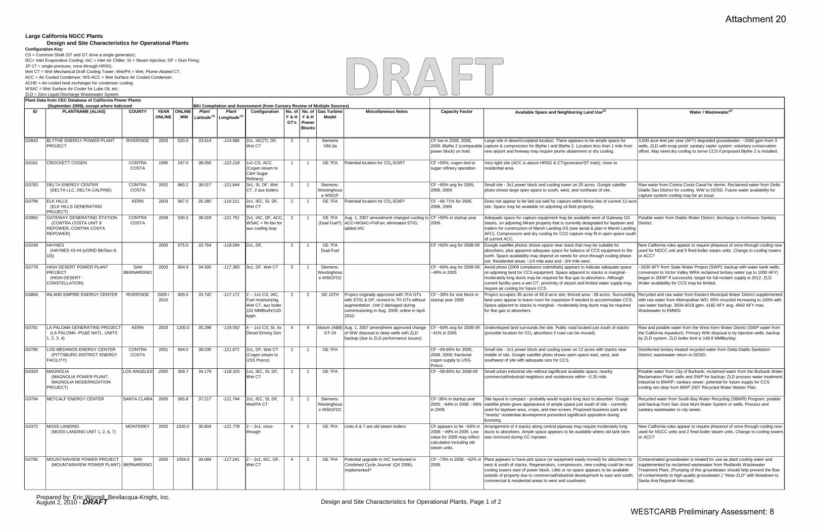
Large California NGCC PlantsDesign and Site Characteristics for Operational Plants
Configuration Key:CS = Common Shaft (ST and GT drive a single generator); IEC= Inlet Evaporative Cooling; IAC = Inlet Air Chiller; SI = Steam Injection; DF = Duct Firing;1P-1T = single-pressure, once-through HRSG; Wet CT = Wet Mechanical Draft Cooling Tower; Wet/PA = Wet, Plume-Abated CT; ACC = Air Cooled Condenser; WS-ACC = Wet Surface Air Cooled Condenser; ACHE = Air-cooled heat exchanger for condenser cooling;WSAC = Wet Surface Air Cooler for Lube Oil, etc; ZLD = Zero Liquid Discharge Wastewater SystemPlant Data from CEC Database of California Power Plants
(September 2009), except where italicized BKi Compilation and Assessment (from Cursory Review of Multiple Sources)ID PLANTNAME (ALIAS) COUNTY YEAR
ONLINEONLINE
_MWPlant
Latitude (1)Plant
Longitude (1)Configuration No. of
F & HGT's
No. ofF & HPower
Gas Turbine Model
Miscellaneous Notes Capacity Factor Available Space and Neighboring Land Use(2) Water / Wastewater(3)
Blocks
G0843 BLYTHE ENERGY POWER PLANT PROJECT
RIVERSIDE 2003 520.0 33.614 -114.686 2x1, IAC(?), DF, Wet CT
2 1 Siemens V84.3a
CF low in 2005, 2008, 2009. Blythe 2 (comparable power block) on hold.
Large site in desert/cropland location. There appears to be ample space for capture & compression for Blythe I and Blythe 2. Location less than 1 mile from new airport and freeway may require plume abatement or dry cooling.
3,000 acre-feet per year (AFY) degraded groundwater; ~2000 gpm from 3 wells, ZLD with evap pond; sanitary septic system; voluntary conservation offset. May need dry cooling to serve CCS if proposed Blythe 2 is installed.
G0161 CROCKETT COGEN CONTRA COSTA
1995 247.0 38.056 -122.218 1x1-CS, ACC (Cogen steam to C&H Sugar Refinery)
1 1 GE 7FA Potential location for CO2-EOR? CF <50%; cogen tied to sugar refinery operation.
Very tight site (ACC is above HRSG & CT/generator/ST train); close to residential area.
G0783 DELTA ENERGY CENTER (DELTA LLC, DELTA-CALPINE)
CONTRA COSTA
2002 860.2 38.017 -121.844 3x1, SI, DF, Wet CT, 2 aux boilers
3 1 Siemens-Westinghous
e W501F
CF ~65% avg for 2005, 2008, 2009.
Small site - 3x1 power block and cooling tower on 20 acres. Google satellite photo shows large open space to south, west, and northeast of site.
Raw water from Contra Costa Canal for demin. Reclaimed water from Delta Diablo San District for cooling. WW to DDSD. Future water availability for capture system cooling may be an issue.
G0799 ELK HILLS (ELK HILLS GENERATING PROJECT)
KERN 2003 567.0 35.280 -119.311 2x1, IEC, SI, DF, Wet CT
2 1 GE 7FA Potential location for CO2-EOR? CF ~66-71% for 2005, 2008, 2009.
Does not appear to be laid out well for capture within fence-line of current 12-acre site. Space may be available on adjoining oil field property.
G0950 GATEWAY GENERATING STATION (CONTRA COSTA UNIT 8 REPOWER, CONTRA COSTA REPOWER)
CONTRA COSTA
2009 530.0 38.018 -121.761 2x1, IAC, DF, ACC, WSAC + fin-fan for aux cooling loop
2 1 GE 7FA(Dual Fuel?)
Aug. 1, 2007 amendment changed cooling to ACC+WSAC+FinFan; eliminated STIG; added IAC
CF >50% in startup year 2009.
Adequate space for capture equipment may be available west of Gateway GS stacks, on adjoining Mirant property that is currently designated for laydown and trailers for construction of Marsh Landing GS (see aerial & plan in Marsh Landing AFC). Compressors and dry cooling for CO2 capture may fit in open space south of current ACC.
Potable water from Diablo Water District; discharge to Ironhouse Sanitary District.
G0249 HAYNES(HAYNES #3 #4 ( GRID Bl /G 9
2005 575.0 33.764 -118.094 2x1, DF, 2 1 GE 7FAD l F l
CF >60% avg for 2008-09 Google satellite photos shows space near stack that may be suitable for b b l t d t f b l f CCS i t t th
New California rules appear to require phaseout of once-through cooling now d f NGCC it d 5 fi d b il t it Ch t li t (HAYNES #3-#4 (eGRID Blr/Gen 9-
10))Dual-Fuel absorbers, plus apparent adequate space for balance of CCS equipment to the
north. Space availability may depend on needs for once-through cooling phase-out. Residential areas ~1/4 mile east and ~3/4 mile west.
used for NGCC unit and 5 fired-boiler steam units. Change to cooling towers or ACC?
G0778 HIGH DESERT POWER PLANT PROJECT (HIGH DESERT - CONSTELLATION)
SAN BERNARDINO
2003 854.9 34.595 -117.365 3x1, DF, Wet CT 3 1 Siemens-Westinghouse W501FD2
CF ~60% avg for 2008-09; ~49% in 2005
Aerial photo (2009 compliance submittals) appears to indicate adequate space on adjoining land for CCS equipment. Space adjacent to stacks is marginal - moderately long ducts may be required for flue gas to absorbers. Although current facility uses a wet CT, proximity of airport and limited water supply may require air cooling for future CCS.
~3200 AFY from State Water Project (SWP); backup with water bank wells; conversion to Victor Valley WRA reclaimed tertiary water (up to 1000 AFY) began in 2009? If successful, target for full reclaim supply is 2012. ZLD. Water availability for CCS may be limited.
G0868 INLAND EMPIRE ENERGY CENTER RIVERSIDE 2009 / 2010
800.0 33.742 -117.171 2 -- 1x1-CS, IAC, Fuel moisturizing, Wet CT, aux boiler 152 MMBtu/hr/120 kpph
2 2 GE 107H Project originally approved with 7FA GTs with STIG & DF; revised to 7H GTs without augmentation. Unit 2 damaged during commissioning in Aug. 2009; online in April 2010.
CF ~30% for one block in startup year 2009.
Project occupies 35 acres of 45.8-acre site; fenced area ~28 acres. Surrounding land uses appear to leave room for expansion if needed to accommodate CCS. Space adjacent to stacks is marginal - moderately long ducts may be required for flue gas to absorbers.
Recycled and raw water from Eastern Municipal Water District supplemented with raw water from Metropolitan WD; 95% recycled increasing to 100% with raw water backup. 3034-4018 gpm. 4182 AFY avg, 4842 AFY max. Wastewater to EMWD.
G0781 LA PALOMA GENERATING PROJECT (LA PALOMA -PG&E NATL. UNITS 1, 2, 3, 4)
KERN 2003 1200.0 35.296 -119.592 4 -- 1x1-CS, SI, 4x Diesel Emerg Gen
4 4 Alstom (ABB) GT-24
Aug. 1, 2007 amendment approved change of WW disposal to deep wells with ZLD backup (due to ZLD performance issues).
CF ~60% avg for 2008-09; ~41% in 2005
Undeveloped land surrounds the site. Public road located just south of stacks (possible location for CO2 absorbers if road can be moved).
Raw and potable water from the West Kern Water District (SWP water from the California Aqueduct). Primary WW disposal is by injection wells, backup by ZLD system. ZLD boiler limit is 148.8 MMBtu/day.
G0780 LOS MEDANOS ENERGY CENTER (PITTSBURG DISTRICT ENERGY FACILITY)
CONTRA COSTA
2001 594.0 38.030 -121.871 2x1, DF, Wet CT (Cogen steam to USS Posco)
2 1 GE 7FA CF ~59-65% for 2005, 2008, 2009; fractional cogen supply to USS-Posco.
Small site - 2x1 power block and cooling tower on 12 acres with stacks near middle of site. Google satellite photo shows open space east, west, and southwest of site with adequate size for CCS.
Disinfected tertiary treated recycled water from Delta Diablo Sanitation District; wastewater return to DDSD.
G0329 MAGNOLIA LOS ANGELES 2005 309.7 34.179 -118.315 1x1, IEC, SI, DF, 1 1 GE 7FA CF ~58-60% for 2008-09 Small urban industrial site without significant available space; nearby Potable water from City of Burbank; reclaimed water from the Burbank Water G0329 MAGNOLIA (MAGNOLIA POWER PLANT, MAGNOLIA MODERNIZATION PROJECT)
LOS ANGELES 2005 309.7 34.179 118.315 1x1, IEC, SI, DF, Wet CT
1 1 GE 7FA CF 58 60% for 2008 09 Small urban industrial site without significant available space; nearby commercial/industrial neighbors and residences within ~0.25 mile.
Potable water from City of Burbank; reclaimed water from the Burbank Water Reclamation Plant; wells and SWP for backup; ZLD process water treatment; industrial to BWRP; sanitary sewer; potential for future supply for CCS cooling not clear from BWP 2007 Recycled Water Master Plan.
G0794 METCALF ENERGY CENTER SANTA CLARA 2005 565.8 37.217 -121.744 2x1, IEC, SI, DF, Wet/PA CT
2 1 Siemens-Westinghouse W501FD2
CF~36% in startup year 2005; ~64% in 2008; ~56% in 2009.
Site layout is compact - probably would require long duct to absorber. Google satellite photo gives appearance of ample space just south of site - currently used for laydown area, crops, and tree-screen. Proposed business park and "nearby" residential development presented significant opposition during licensing.
Recycled water from South Bay Water Recycling (SBWR) Program; potable and backup from San Jose Muni Water System or wells. Process and sanitary wastewater to city sewer.
G0372 MOSS LANDING (MOSS LANDING UNIT 1, 2, 6, 7)
MONTEREY 2002 1020.0 36.804 -121.778 2 -- 2x1, once-through
4 2 GE 7FA Units 6 & 7 are old steam boilers CF appears to be ~54% in 2008; ~49% in 2009. Low value for 2005 may reflect calculation including old steam units.
Arrangement of 4 stacks along central pipeway may require moderately long ducts to absorbers. Ample space appears to be available where old tank farm was removed during CC repower.
New California rules appear to require phaseout of once-through cooling now used for NGCC units and 2 fired-boiler steam units. Change to cooling towers or ACC?
G0795 MOUNTAINVIEW POWER PROJECT (MOUNTAINVIEW POWER PLANT)
SAN BERNARDINO
2005 1054.0 34.084 -117.241 2 -- 2x1, IEC, DF, Wet CT
4 2 GE 7FA Potential upgrade to IAC mentioned in Combined Cycle Journal (Q4 2006). Implemented?
CF ~73% in 2008; ~62% in 2009.
Plant appears to have plot space (or equipment easily moved) for absorbers to west & south of stacks. Regenerators, compressors, new cooling could be near cooling towers east of power block. Little or no space appears to be available outside of property due to commercial/industrial development to east and south; commercial & residential areas to west and southwest.
Contaminated groundwater is treated for use as plant cooling water and supplemented by reclaimed wastewater from Redlands Wastewater Treatment Plant. (Pumping of this groundwater should help prevent the flow of contaminants to high-quality groundwater.) "Near-ZLD" with blowdown to Santa Ana Regional Intercept.
Prepared by: Eric Worrell, Bevilacqua-Knight, Inc.August 2, 2010 - DRAFT Design and Site Characteristics for Operational Plants, Page 1 of 2
WESTCARB Preliminary Assessment: 8
Attachment 20
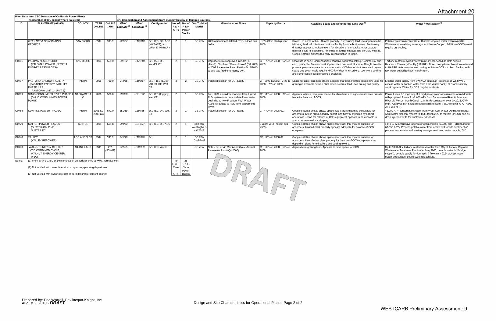
Plant Data from CEC Database of California Power Plants (September 2009), except where italicized BKi Compilation and Assessment (from Cursory Review of Multiple Sources)
ID PLANTNAME (ALIAS) COUNTY YEAR ONLINE
ONLINE_MW
Plant Latitude (1)
Plant Longitude (1)
Configuration No. ofF & HGT's
No. ofF & HPowerBlocks
Gas Turbine Model
Miscellaneous Notes Capacity Factor Available Space and Neighboring Land Use(2) Water / Wastewater(3)
OTAY MESA GENERATING PROJECT
SAN DIEGO 2009 600.0 32.577 -116.913 2x1, IEC, DF, ACC (+WSAC?), aux boiler 87 MMBtu/hr
2 1 GE 7FA 2003 amendment deleted STIG; added aux boiler.
~15% CF in startup year 2009.
Site is ~15 acres within ~46 acre property. Surrounding land use appears to be fallow ag land. ~1 mile to correctional facility & some businesses. Preliminary drawings appear to indicate room for absorbers near stacks; other capture facilities could fit elsewhere. Amended drawings not available on CEC website. Google satellite pictures too early in construction to judge.
Potable water from Otay Water District; recycled water when available. Wastewater to existing sewerage in Johnson Canyon. Addition of CCS would require dry cooling.
G0861 PALOMAR ESCONDIDO (PALOMAR POWER (SEMPRA ENERGY RESOURCES))
SAN DIEGO 2006 559.0 33.122 -117.118 2x1, IAC, DF, Wet/PA CT
2 1 GE 7FA Upgrade to IAC approved in 2007 (in place?). Combined Cycle Journal (Q4 2006) -- 2007 Pacesetter Plant. Petition 5/18/2010 to add gas-fired emergency gen.
CF ~73% in 2008; ~67% in 2009.
Small site in noise- and emissions-sensitive suburban setting. Commercial due east; residential 1/4 mile west. Open space due west at time of Google satellite photo appears adequate for absorbers with ~300 feet of duct from stack; open space due south would require ~500 ft of duct to absorbers. Low-noise cooling and compression could present a challenge.
Tertiary treated recycled water from City of Escondido Hale Avenue Resource Recovery Facility (HARRF). Brine cooling tower blowdown returned to HARRF. Adequacy for wet cooling for future CCS not clear. Backup with raw water authorized post-certification.
p p g
G0797 PASTORIA ENERGY FACILITY (PASTORIA ENERGY FACILITY PHASE 1 & 2, PASTORIA UNIT 1 - UNIT 2)
KERN 2005 760.0 34.956 -118.844 2x1 + 1x1, IEC or IAC, SI, DF, Wet CT
3 2 GE 7FA Potential location for CO2-EOR? CF~39% in 2005; ~74% in 2008; ~75% in 2009.
Space for absorbers near stacks appears marginal. Plentiful space now used for grazing is available outside plant fence. Nearest land uses are ag and quarry.
Existing water supply from SWP CA aqueduct (purchase of WRMWSD excess water or banked water from Kern Water Bank); ZLD and sanitary septic system. Water for CCS may be available.
G0889 SMUD CONSUMNES RIVER PHASE 1 (SMUD CONSUMNES POWER PLANT)
SACRAMENTO
2006 500.0 38.338 -121.122 2x1, IEC (fogging), Wet CT
2 1 GE 7FA Feb. 2009 amendment added filter & rev'd ZLD system to accommodate lower water qual. due to new Freeport Reg'l Water Authority outake to FSC from Sacramento River.
CF ~88% in 2008; ~79% in 2009.
Appears to have room near stacks for absorbers and agricultural space outside fence for balance of CCS.
Phase I uses 2.5 mgd avg, 3.5 mgd peak; water requirements would double with proposed Phase 2. ~2,663 AFY from Sacramento River & American River via Folsom South Canal (U.S. BOR contract renewal by 2012; CVP Impr. Act gives fish & wildlife equal rights to water); ZLD (original AFC--4,000 AFY w/o ZLD).
G0784 SUNRISE POWER PROJECT KERN 2001-SC 2003-CC
572.0 35.210 -119.585 2x1, IEC, DF, Wet CT
2 1 GE 7FA Potential location for CO2-EOR? CF ~72% in 2008-09. Google satellite photos shows space near stacks that may be suitable for absorbers. Site is surrounded by desert land heavily impacted by oil field operations -- land for balance of CCS equipment appears to be available in space between wells and piping.
~3,900 AFY consumption; water from West Kern Water District well fields; wastewater disposal system to TCI Station 2-22 to recycle for EOR plus six deep injection wells for wastewater disposal.
G0779 SUTTER POWER PROJECT (SUTTER-CALPINE, SUTTER EC)
SUTTER 2001 551.8 39.053 -121.694 2x1, IEC, DF, ACC 2 1 Siemens-Westinghous
e W501F
2 years w CF <50%; avg >50%.
Google satellite photos shows space near stack that may be suitable for absorbers. Unused plant property appears adequate for balance of CCS equipment.
>140 GPM annual average water consumption (60,000 gpd -- 318,000 gpd; 67-356 AFY). Process/potable water from onsite well; onsite treatment of process wastewater and sanitary sewage treatment; water recycle; ZLD.
G0648 VALLEY (VALLEY REPOWER)
LOS ANGELES 2004 533.0 34.248 -118.390 2x1 2 1 GE 7FADual-Fuel
CF ~55% in 2008-09. Google satellite photos shows space near stack that may be suitable for absorbers. Use of other plant property for balance of CCS equipment may depend on plans for old boilers and cooling towers.
G0900 WALNUT ENERGY CENTER(TID COMBINED CYCLE
STANISLAUS 2006 275 (300 6?)
37.555 -120.989 2x1, IEC, Wet CT GE 7EA Note - GE 7EA; Combined Cycle Journal Pacesetter Plant (Q4 2006)
CF ~60% in 2008; ~58% in 2009
Adjoins farm/grazing land. Appears to have space for CCS. Up to 1800 AFY tertiary treated wastewater from City of Turlock Regional Wastewater Treatment Plant (after May 2006; potable water for "bridge (TID COMBINED CYCLE,
WALNUT ENERGY CENTER, WEC)
(300.6?) Pacesetter Plant (Q4 2006) 2009. Wastewater Treatment Plant (after May 2006; potable water for "bridge supply"); potable supply for domestic & firewater); ZLD process water treatment; sanitary septic system/leachfield.
Notes: (1) From EPA e-GRID or pointer location on aerial photos at www.msrmaps.com 49 28
(2) Not verified with owner/operator or city/county planning department.F- & H-Class
F- & H-Class
(3) Not verified with owner/operator or permitting/enforcement agency. GTs Power Blocks
Prepared by: Eric Worrell, Bevilacqua-Knight, Inc.August 2, 2010 - DRAFT Design and Site Characteristics for Operational Plants, Page 2 of 2
WESTCARB Preliminary Assessment: 9
Attachment 20
WESTCARB NGCC-CCS StudyLarge California NGCC Plants
Generation/Emissions Data for Operational PlantsConfiguration Key:CS = Common Shaft (ST and GT drive a single generator); IEC= Inlet Evaporative Cooling; IAC = Inlet Air Chiller; SI = Steam Injection; DF = Duct Firing;1P-1T = single-pressure, once-through HRSG; Wet CT = Wet Mechanical Draft Cooling Tower; Wet/PA = Wet, Plume-Abated CT; ACC = Air Cooled Condenser; WS-ACC = Wet Surface Air Cooled Condenser; ACHE = Air-cooled heat exchanger for condenser cooling;WSAC = Wet Surface Air Cooler for Lube Oil, etc; ZLD = Zero Liquid Discharge Wastewater SystemPlant Data from CEC Database of California Power Plants Operating Data from 2009 December EIA-923 Monthly Time Series File Operating Data from 2008 December EIA-923 Monthly Time Series File Operating Data from EPA eGRID2007 Version 1.1 Plant File (Year 2005 Data)
(September 2009), except where italicized (italicized values calculated by BKi) (1) (italicized values calculated by BKi) (1)
ID PLANTNAME (ALIAS) COUNTY YEAR ONLINE
ONLINE_MW
Total Fuel Consumption
MMBtu
Total Net Generation
(MWh)
Net Heat Rate
(Btu/kWh)
Est'd CO 2
Emissions (Tons)
Est'd Capacity
Factor
Total Fuel Consumption
MMBtu
Total Net Generation
(MWh)
Net Heat Rate
(Btu/kWh)
Est'd CO 2
Emissions (Tons)
Est'd Capacity
Factor
Plant capacity factor
Plant nameplate
capacity (MW-gross)
Plant annual heat input (MMBtu)
Plant unadjusted annual heat
input
Plant annual net
generation (MWh)
Plant annual CO2
emissions (tons)
Plant unadjusted annual CO2
emissions
Annual CO2
emission rate (lb/MWh
output)
Plant nominal heat rate (Btu/kWh)
(adjusted)(6)gross) input (MMBtu)
(MWh) (tons) (adjusted)(6)
emissions (tons)
output) (adjusted)(6)
(adjusted)(6)
G0843 BLYTHE ENERGY POWER PLANT PROJECT RIVERSIDE 2003 520.0 10,176,154 1,406,429 7,235 604,718 0.309 10,355,505 1,383,869 7,483 615,412 0.304 0.176 591.0 6,684,426 6,684,426 911,018 397,245 397,245 872 7337
G0161 CROCKETT COGEN CONTRA COSTA
1995 247.0 8,040,367 682,429 11,782 477,799 0.315 9,309,402 888,311 10,480 553,211 0.411 0.429 247.4 8,213,544 10,056,380 929,544.2 480,364 588,141 1034 8836
G0783 DELTA ENERGY CENTER (DELTA LLC, DELTA-CALPINE)
CONTRA COSTA
2002 860.2 36,882,025 5,013,277 7,357 2,191,714 0.665 35,521,394 4,825,914 7,361 2,110,859 0.640 0.648 943.5 37,988,940 37,988,940 5,359,470 2,257,632 2,257,632 842 7088
G0799 ELK HILLS (ELK HILLS GENERATING PROJECT)
KERN 2003 567.0 24,205,962 3,452,893 7,010 1,438,439 0.695 24,926,324 3,551,893 7,018 1,481,247 0.715 0.658 623.0 24,680,270 24,680,270 3,590,648 1,466,706 1,466,706 817 6873
G0950 GATEWAY GENERATING STATION (CONTRA COSTA UNIT 8 REPOWER, CONTRA COSTA REPOWER)
CONTRA COSTA
2009 530.0 18,096,256 2,490,206 7,267 1,075,370 0.536
G0249 HAYNES (HAYNES #3-#4 (eGRID Blr/Gen 9-10))
2005 575.0 21,138,712 2,953,831 7,156 1,256,168 0.586 27,257,511 3,277,428 8,317 1,619,778 0.651 16,649,400 31,555,920 989,294(2) 1,875,177
G0778 HIGH DESERT POWER PLANT PROJECT (HIGH DESERT - CONSTELLATION)
SAN BERNARDINO
2003 854.9 29,877,167 4,265,280 7,005 1,775,451 0.570 33,516,478 4,704,901 7,124 1,991,717 0.628 0.490 852.0 26,463,888 26,463,888 3,656,116 1,572,707 1,572,707 860 7238
G0868 INLAND EMPIRE ENERGY CENTER RIVERSIDE 2009 / 2010
800.0 7,613,603 1,110,335 6,857 452,438 0.158
G0781 LA PALOMA GENERATING PROJECT(LA PALOMA PG&E NATL UNITS 1 2 3 4)
KERN 2003 1200.0 44,964,443 6,339,567 7,093 2,672,012 0.603 45,144,224 6,185,233 7,299 2,682,696 0.588 0.421 1,200.0 36,424,861 36,424,861 4,427,010 2,164,683 2,164,683 978 8228 (LA PALOMA -PG&E NATL. UNITS 1, 2, 3, 4)
G0780 LOS MEDANOS ENERGY CENTER (PITTSBURG DISTRICT ENERGY FACILITY)
CONTRA COSTA
2001 594.0 24,422,613 3,358,184 7,273 1,451,314 0.645 22,591,317 3,064,966 7,371 1,342,489 0.589 0.605 678.3 26,035,686 26,670,505 3,594,588 1,547,266 1,584,993 861 7243
G0329 MAGNOLIA (MAGNOLIA POWER PLANT, MAGNOLIA MODERNIZATION PROJECT)
LOS ANGELES 2005 309.7 11,665,710 1,623,642 7,185 693,235 0.598 11,387,145 1,571,797 7,245 676,681 0.579 0.016(3) 387.6 2,867,301 2,867,301 52,918 170,418 170,418 6441 54189
G0794 METCALF ENERGY CENTER SANTA CLARA 2005 565.8 19,171,009 2,778,697 6,899 1,139,237 0.561 21,624,466 3,152,211 6,860 1,285,034 0.636 0.363 635.0 15,880,602 15,880,602 2,020,895 943,761 943,761 934 7858G0372 MOSS LANDING
(MOSS LANDING UNIT 1, 2, 6, 7)MONTEREY 2002 1020.0 34485771(5) 4,386,230(5) 7,862 2,049,317 (5) 0.491 35,184,497(5) 4,846,562(5) 7,260 (5) 2,090,839 (5) 0.542 (5) 0.217(2) 2802(2) 39,993,240 39,993,240 5,331,135(2) 2,376,736(2) 2,376,736 892(2) 7502(2)
G0795 MOUNTAINVIEW POWER PROJECT (MOUNTAINVIEW POWER PLANT)
SAN BERNARDINO
2005 1054.0 43,862,609 5,749,671 7,629 2,606,536 0.623 49,996,825 6,691,295 7,472 2,971,061 0.725 0.015(3) 1,108.1 1,549,386 1,549,386 148,559 92,077 92,077 1240 10429
OTAY MESA GENERATING PROJECT SAN DIEGO 2009 600.0 5,617,964 791,646 7,097 333,848 0.151G0861 PALOMAR ESCONDIDO
(PALOMAR POWER (SEMPRA ENERGY RESOURCES))
SAN DIEGO 2006 559.0 23,115,079 3,296,813 7,011 1,373,614 0.673 24,986,117 3,590,373 6,959 1,484,800 0.733
G0797 PASTORIA ENERGY FACILITY (PASTORIA ENERGY FACILITY PHASE 1 & 2, PASTORIA UNIT 1 - UNIT 2)
KERN 2005 760.0 34,618,431 4,979,707 6,952 2,057,200 0.748 34,267,796 4,914,751 6,972 2,036,364 0.738 0.368 779.0 13,989,962 13,989,962 2,514,221 831,401 831,401 661 5564
G0889 SMUD CONSUMNES RIVER PHASE 1 (SMUD CONSUMNES POWER PLANT)
SACRAMENTO 2006 500.0 24,164,354 3,436,323 7,032 1,435,967 0.785 27,111,694 3,838,140 7,064 1,611,112 0.876
G0784 SUNRISE POWER PROJECT KERN 2001-SC 572 0 25 139 744 3 581 251 7 020 1 493 929 0 715 26 194 929 3 604 944 7 266 1 556 634 0 719 0 637 605 4 35 635 445 35 635 445 3 378 274 2 107 400 2 107 400 1248 10548G0784 SUNRISE POWER PROJECT KERN 2001-SC 2003-CC
572.0 25,139,744 3,581,251 7,020 1,493,929 0.715 26,194,929 3,604,944 7,266 1,556,634 0.719 0.637 605.4 35,635,445 35,635,445 3,378,274 2,107,400 2,107,400 1248 10548
G0779 SUTTER POWER PROJECT (SUTTER-CALPINE, SUTTER EC)
SUTTER 2001 551.8 17,261,195 2,315,457 7,455 1,025,747 0.479 21,561,584 2,898,969 7,438 1,281,297 0.600 0.436 636.0 17,293,068 17,293,068 2,429,452 1,027,703 1,027,703 846 7118
G0648 VALLEY (VALLEY REPOWER)
LOS ANGELES 2004 533.0 18,574,203 2,551,690 7,279 1,103,772 0.547 18,520,679 2,547,518 7,270 1,100,591 0.546 741(4) 18,286,822 18,315,262 2,488,485 1,086,768 1,088,459 873
G0900 WALNUT ENERGY CENTER (TID COMBINED CYCLE, WALNUT ENERGY CENTER, WEC)
STANISLAUS 2006 275 (300.6?)
11,916,521 1,523,778 7,820 708,139 0.579 12,339,979 1,577,680 7,822 733,303 0.599
Notes: (1) Net Heat Rate (Btu/kWh) = Total Fuel Consumption (MMBtu/year)/Total Net Generation (MWh) Est'd annual CO2 (tons) = Total Fuel Consumption (MMBtu/year) x emission rate (~118.85 lb-CO2/MMBtu input) "Est'd Capacity Factor" = ("Total Net Generation (MWh)") / ("ONLINE_MW" x 8760)(2) Data includes ALL generators at the plant -- F-Class and H-Class CTGs, STGs in combined cycle with CTGs; CTG peakers; STGs supplied by older fired boilers.(3) Plant commercial operation commenced late in 2005.(4) Anomaly due to existing STG oversized for HRSG steam output after repower?(5) May not be accurate due to inconsistencies in monthly reporting.(6) Adjusted values for heat input and CO2 emissions exclude portion attributable to cogeneration steam production.
Prepared by: Eric Worrell, Bevilacqua-Knight, Inc.August 2, 2010 - DRAFT Generation/Emission Data for Operational NGCC Plants, Page 1 of 1
WESTCARB Preliminary Assessment: 10
Attachment 20
California Map of NGCC Plants and Potential CO2 Storage Locations
DRAFT
September 7, 2010 - DRAFT WESTCARB Preliminary Assessment: 11
Attachment 20