welding procedure qualification tests of steels ... - iacs · welding procedure qualification tests...
TRANSCRIPT
W28
Page 1 of 25 IACS Req. 2005/Rev.2 2012
W28(cont)
Welding procedure qualification tests of steelsfor hull construction and marine structures1. Scope
1.1 This document gives requirements for qualification tests of welding procedures intendedfor the use of weldable steels as specified in UR W7, UR W8, UR W11 and UR W16 for hullconstruction and marine structures.
1.2 This document specifically excludes the welding procedure specified in UR W1.
1.3 All new welding procedure qualification tests are to be carried out in accordance withthis document from 1 July 2007.
1.4 This document does not invalidate welding procedure qualification tests made andaccepted by the Classification Society before 1 July 2007 provided the welding procedurequalification tests are considered by the Classification Society to meet the technical intent ofthis UR or have been qualified in accordance with the recognized standards such as ISO, EN,AWS, JIS or ASME.
2. General
2.1 Welding procedure qualification tests are intended to verify that a manufacturer isadequately qualified to perform welding operations using a particular procedure.
2.2 In general welding procedure tests are to reflect fabrication conditions in respect towelding equipment, inside or outside fabrication, weld preparation, preheating and any post-weld heat treatment. It is to be the manufacturer’s responsibility to establish and documentwhether a procedure is suitable for the particular application.
2.3 For the welding procedure approval the welding procedure qualification test is to becarried out with satisfactory results. Welding procedure specifications are to refer to the testresults achieved during welding procedure qualification testing.
2.4 Welding procedures qualified at a manufacturer are valid for welding in workshopsunder the same technical and quality management.
Note:
1. This UR is to be uniformly implemented by IACS Societies on ships contracted forconstruction from 1 January 2007 as well as the manufacturing of which is commencedon or after 1 January 2007.
2. The “contracted for construction” date means the date on which the contract to build thevessel is signed between the prospective owner and the shipbuilder. For further detailsregarding the date of “contract for construction”, refer to IACS Procedural Requirement(PR) No. 29.
3. Rev.2 of this UR is to be uniformly implemented by IACS Societies on ships contractedfor construction on or after 1 January 2013.
W28(June2005)(Rev.1Nov2006)(Rev.2Mar2012)
W28
Page 2 of 25 IACS Req. 2005/Rev.2 2012
W28(cont)
3 Welding procedure specification
3.1 Preliminary welding procedure specification and welding procedure specification
3.1.1 A welding procedure specification (WPS) is to be prepared by the shipyard ormanufacturer which intends to perform the welding procedure qualification test. Thisdocument is also referred to as a preliminary welding procedure specification (pWPS). ThepWPS can be modified and amended during procedure tests as deemed necessary howeverit is to define all relevant variables as mentioned in the WPS (refer to ISO 15614 or otherrecognized standards).
3.1.2 The shipyard or manufacturer is to submit to the Society a pWPS for review prior to thetests. In case that the test pieces welded according to the pWPS show unacceptable resultsthe pWPS is to be adjusted by the shipyard or manufacturer. The new pWPS is to beprepared and the test pieces welded in accordance with the new pWPS.
3.1.3 The WPS is to be used as a basis for the production welds, and upon satisfactorycompletion of the tests based on the pWPS, the Society may approve it as a WPS. In casethat a WPS is approved by the Society the approval range is to be in compliance with section5.
4. Qualification of welding procedures
4.1 General
4.1.1 Preparation and welding of test pieces are to be carried out in accordance with thepWPS and under the general condition of production welding which it represents.
4.1.2 Welding of the test assemblies and testing of test specimens are to be witnessed by theSurveyor.
4.1.3 If tack welds and/or start and stop points are a condition of the weld process they are tobe fused into the joint and are to be included in the test assemblies.
4.2 Butt weld
4.2.1 Assembly of test pieces
The test assembly is to be of a size sufficient to ensure a reasonable heat distribution andaccording to Fig. 1 with the minimum dimensions:
- manual or semi-automatic welding:
width = 2a, a = 3 x t, min 150 mmlength b = 6 x t, min 350 mm
- automatic welding:
width = 2a, a = 4 x t, min 200 mmlength b = 1000 mm
W28
Page 3 of 25 IACS Req. 2005/Rev.2 2012
W28(cont)
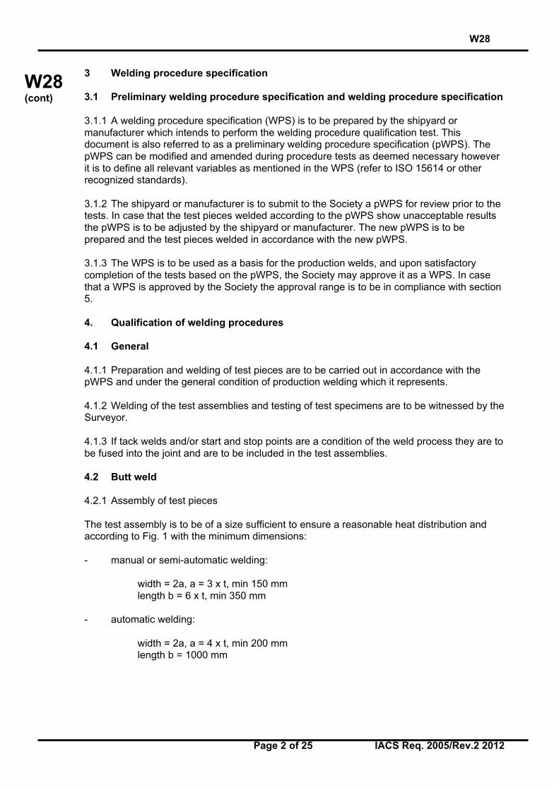
Fig.1 Test assembly for butt weld
For hull structural steel plates impact tested in the longitudinal direction (CVN-L) in UR W11,the butt weld of the test piece is perpendicular to the rolling direction of the two plates.
For high strength quenched and tempered steel plates impact tested in the transversedirection (CVN-T) in UR W16, the butt weld of the test piece is parallel to the rolling directionof the two plates.
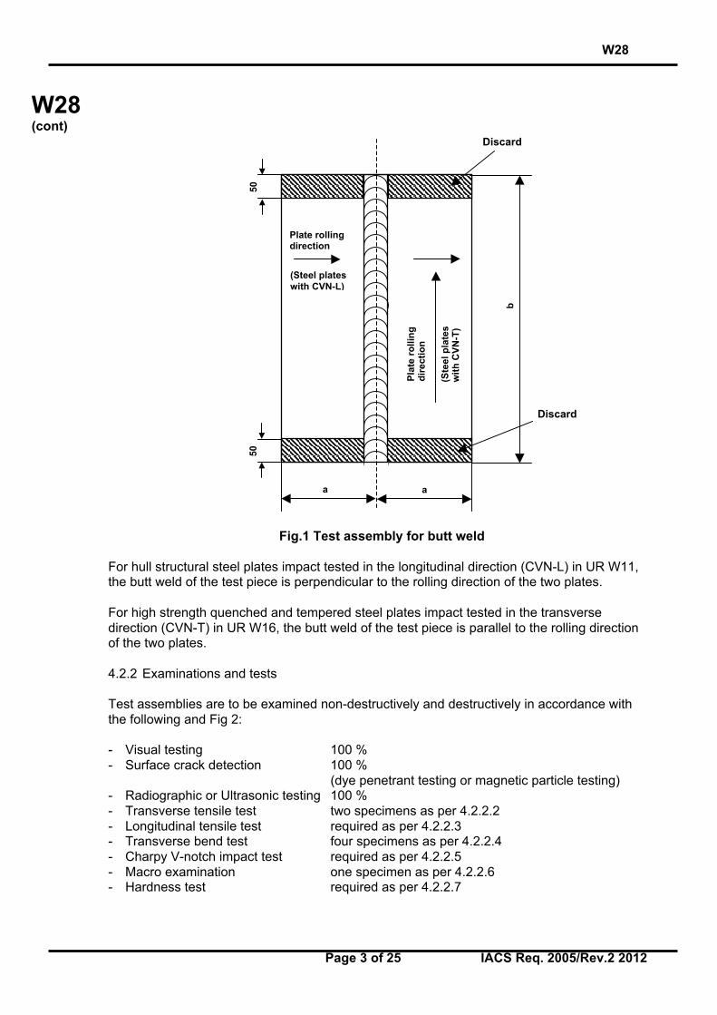
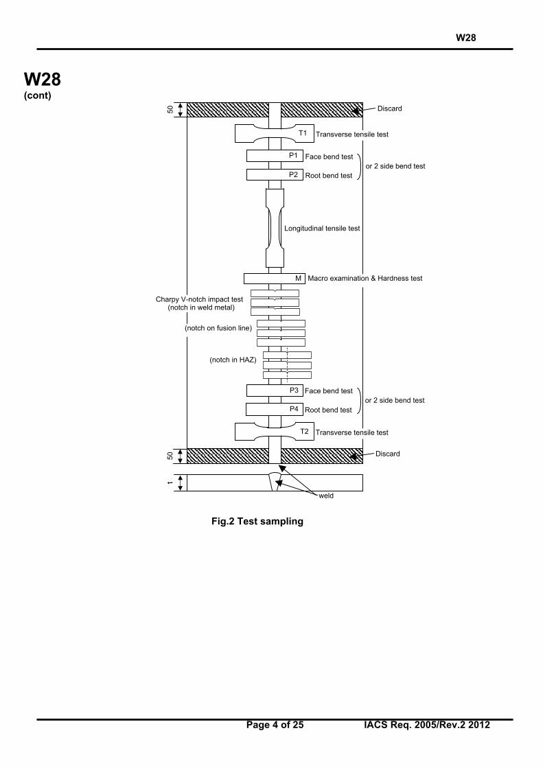
4.2.2 Examinations and tests
Test assemblies are to be examined non-destructively and destructively in accordance withthe following and Fig 2:
- Visual testing 100 %- Surface crack detection 100 %
(dye penetrant testing or magnetic particle testing)- Radiographic or Ultrasonic testing 100 %- Transverse tensile test two specimens as per 4.2.2.2- Longitudinal tensile test required as per 4.2.2.3- Transverse bend test four specimens as per 4.2.2.4- Charpy V-notch impact test required as per 4.2.2.5- Macro examination one specimen as per 4.2.2.6- Hardness test required as per 4.2.2.7
Plate rollingdirection
(Steel plateswith CVN-L)
(Ste
el p
late
sw
ith
CV
N-T
)
Pla
te r
olli
ng
dir
ecti
on
a a
5050
b
Discard
Discard
W28
Page 4 of 25 IACS Req. 2005/Rev.2 2012
W28(cont)
Fig.2 Test sampling
Longitudinal tensile test
Transverse tensile test
Face bend test
Root bend testor 2 side bend test
Transverse tensile test
Macro examination & Hardness test
Charpy V-notch impact test (notch in weld metal)
(notch in HAZ)
5050 Discard
Discard
weld
(notch on fusion line)
Face bend test
Root bend testor 2 side bend test
T1
P1
P2
T2
P3
P4
M
W28
Page 5 of 25 IACS Req. 2005/Rev.2 2012
W28(cont)
4.2.2.1 Non-destructive testing
Test assemblies are to be examined by visual and by non-destructive testing prior to thecutting of test specimen. In case that any post-weld heat treatment is required or specified,non-destructive testing is to be performed after heat treatment. For steels according to URW16 with specified minimum yield strength of 420 N/mm2 and above the non-destructivetesting is to be delayed for a minimum of 48 hrs, unless heat treatment has been carried out.NDT procedures are to be agreed with the Society.
Imperfections detected by visual or non-destructive testing are to be assessed in accordancewith ISO 5817, class B, except for excess weld metal and excess of penetration for which thelevel C applies.
4.2.2.2 Transverse tensile test
The testing is to be carried out in accordance with UR W2.4. The tensile strength recorded foreach specimen is not to be less than the minimum required for the base metal.
When butt welds are made between plates of different grades, the tensile strength to beobtained on the welded assembly is to be in accordance with the requirements relating to thesteel grade having lower strength.
4.2.2.3 Longitudinal tensile test
Longitudinal tensile test of deposited weld metal taken lengthways from the weld is requiredfor cases where the welding consumable is not approved by the Society.
The testing is to be carried out in accordance with UR W2.4. The tensile properties recordedfor each specimen are not to be less than the minimum required for the approval of theappropriate grade of consumable.
Where more than one welding process or type of consumable has been used to make thetest weld, test specimens are to be taken from the area of the weld where each was usedwith the exception of those processes or consumables used to make the first weld run or rootdeposit.
4.2.2.4 Bend test
Transverse bend tests for butt joints are to be in accordance with UR W2.6.
The mandrel diameter to thickness ratio (i.e. D/t) is to be that specified for the weldingconsumable (UR W17, UR W23) approvals + 1.
The bending angle is to be 180°. After testing, the test specimens are not to reveal any opendefects in any direction greater than 3 mm. Defects appearing at the corners of a testspecimen during testing are to be investigated case by case.
Two root and two face bend specimens are to be tested. For thickness 12 mm and over, fourside bend specimens may alternatively be tested.
For butt joints in heterogeneous steel plates, face and root longitudinal bend test specimensmay be used instead of the transverse bend test specimens.
W28
Page 6 of 25 IACS Req. 2005/Rev.2 2012
W28(cont)
4.2.2.5 Impact test
a) Normal and higher strength hull structural steels according to UR W11
The positions of specimens are to be in accordance with these requirements. Dimensionsand testing are to be in accordance with the requirements of UR W2.7.
Test specimen with Charpy-V-notch are to be used and sampled from 1 to 2 mm below thesurface of the base metal, transverse to the weld and on the side containing the last weld run.
V-notch specimens are located in the butt-welded joint as indicated in Fig. 1 and 2 of Annex Aand the V-notch is to be cut perpendicular to the surface of the weld.
Test temperature and absorbed energy are to be in accordance with Table 1.
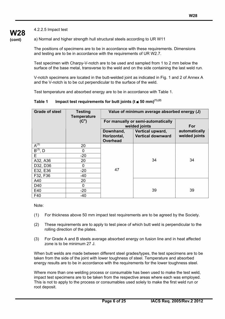
Table 1 Impact test requirements for butt joints (t ≤ 50 mm)(1),(2)
Value of minimum average absorbed energy (J)
For manually or semi-automaticallywelded joints
Grade of steel TestingTemperature
(Co)
Downhand,Horizontal,Overhead
Vertical upward,Vertical downward
Forautomaticallywelded joints
A(3) 20B(3), D 0E -20A32, A36 20D32, D36 0E32, E36 -20F32, F36 -40
34 34
A40 20D40 0E40 -20F40 -40
47
39 39
Note:
(1) For thickness above 50 mm impact test requirements are to be agreed by the Society.
(2) These requirements are to apply to test piece of which butt weld is perpendicular to therolling direction of the plates.
(3) For Grade A and B steels average absorbed energy on fusion line and in heat affectedzone is to be minimum 27 J.
When butt welds are made between different steel grades/types, the test specimens are to betaken from the side of the joint with lower toughness of steel. Temperature and absorbedenergy results are to be in accordance with the requirements for the lower toughness steel.
Where more than one welding process or consumable has been used to make the test weld,impact test specimens are to be taken from the respective areas where each was employed.This is not to apply to the process or consumables used solely to make the first weld run orroot deposit.
W28
Page 7 of 25 IACS Req. 2005/Rev.2 2012
W28(cont)
The testing of sub - size specimen is to be in accordance with UR W2.7.2
b) High strength quenched and tempered steels according to UR W16
Impact test is to be performed as described in the above a).
V-notch specimens are located in the butt welded joint as indicated in Fig. 1 and 2 of Annex Aand the V-notch is to be cut perpendicular to the surface of the weld.
Test temperature and absorbed energy are to be in accordance with the requirements ofbase metal as specified in UR W16.
c) Weldable C and C-Mn hull steel castings and forgings according to UR W7 and UR W8
For base metal with specified impact values test temperature and absorbed energy are to bein accordance with the requirements of the base metal to be welded.
4.2.2.6 Macro examination
The test specimens are to be prepared and etched on one side to clearly reveal the weldmetal, the fusion line and the heat affected zone.
Macro examination is to include about 10 mm unaffected base metal.
The examination is to reveal a regular weld profile, through fusion between adjacent layers ofweld and base metal and the absence of defects such as cracks, lack of fusion etc.
4.2.2.7 Hardness test
Hardness test is required for steels with specified minimum yield strength of ReH ≥ 355N/mm2. The Vickers method HV 10 is normally to be used. The indentations are to be madein the weld metal, the heat affected zone and the base metal measuring and recording thehardness values. At least two rows of indentations are to be carried out in accordance withFig. 1 and 2 of Annex B.
For each row of indentations there is to be a minimum of 3 individual indentations in the weldmetal, the heat affected zones (both sides) and the base metal (both sides). A typicalexample is shown in Annex B.
The results from the hardness test are not to exceed the following:
- Steel with a specified minimum yield strength ReH ≤ 420 N/mm2 ; 350 HV10- Steel with a specified minimum yield strength 420 N/mm2 < ReH ≤ 690 N/mm2 ; 420 HV10
4.3 Fillet welds
4.3.1 Assembly of test pieces
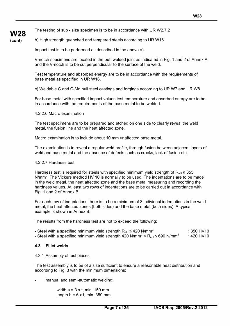
The test assembly is to be of a size sufficient to ensure a reasonable heat distribution andaccording to Fig. 3 with the minimum dimensions:
- manual and semi-automatic welding:
width a = 3 x t, min. 150 mmlength b = 6 x t, min. 350 mm
W28
Page 8 of 25 IACS Req. 2005/Rev.2 2012
W28(cont)
- automatic welding:
width a = 3 x t, min. 150 mmlength b = 1000 mm
Fig.3 Test assembly for fillet weld
4.3.2 Welding of test pieces
The test assembly is welded on one side only. For single run manual and semi-automaticwelding, a stop/restart is to be included in the test length and its position is to be clearlymarked for subsequent examination.
4.3.3 Examinations and tests
Test assemblies are to be examined non-destructively and destructively in accordance withthe following:
- Visual testing 100 %- Surface crack detection 100 %
(dye penetrant testing or magnetic particle testing)- Macro examination two specimen as per 4.3.3.2- Hardness test required as per 4.3.3.3- Fracture test required as per 4.3.3.4
t 1, t 2= plate thickness of test pieces
t 1
t 2
aa
W28
Page 9 of 25 IACS Req. 2005/Rev.2 2012
W28(cont)
4.3.3.1 Non-destructive testing
Test assemblies are to be examined by visual and by non-destructive testing prior to thecutting of test specimen. In case that any post-weld heat treatment is required or specifiednon-destructive testing is to be performed after heat treatment. For steels according to URW16 with specified minimum yield strength of 420 N/mm2 and above the non-destructivetesting is to be delayed for a minimum of 48 hrs, unless heat treatment has been carried out.NDT procedures are to be agreed with the Society.
Imperfections detected by visual or non-destructive testing are to be assessed in accordancewith ISO 5817, class B except for excess convexity and excess throat thickness for which thelevel C applies.
4.3.3.2 Macro examination
The test specimens are to be prepared and etched on one side to clearly reveal the weldmetal, fusion line, root penetration and the heat affected zone.
Macro examination is to include about 10 mm unaffected base metal.
The examination is to reveal a regular weld profile, through fusion between adjacent layers ofweld and base metal, sufficient root penetration and the absence of defects such as cracks,lack of fusion etc.
4.3.3.3 Hardness test
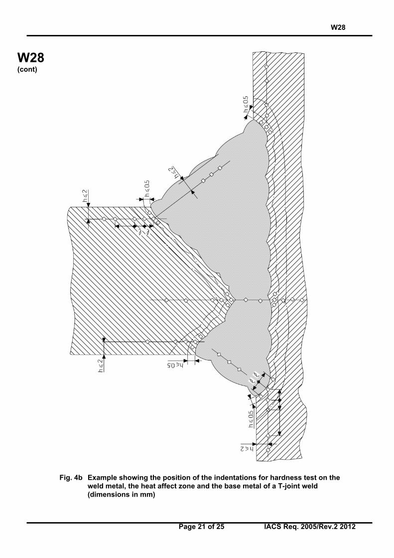
Hardness test is required for steels with a specified minimum yield strength of ReH ≥ 355N/mm2. The Vickers method HV 10 is normally to be used. The indentations are to be madein the weld metal, the heat affected zone and the base metal measuring and recording thehardness values. At least two rows of indentations are to be carried out in accordance withFig. 3, 4a and 4b of Annex B.
For each row of indentations there is to be a minimum of 3 individual indentations in the weldmetal, the heat affected zone (both sides) and the base metal (both sides). A typical exampleis shown in Annex B.
The results from the hardness test are not to exceed the following:
- Steel with a specified minimum yield strength ReH ≤ 420 N/mm2 ; 350 HV10- Steel with a specified minimum yield strength 420 N/mm2 < ReH ≤ 690 N/mm2 ; 420 HV10
4.3.3.4 Fracture test
The fracture test is to be performed by folding the upright plate onto the through plate.Evaluation is to concentrate on cracks, porosity and pores, inclusions, lack of fusion andincomplete penetration. Imperfection that are detected is to be assessed in accordance withISO 5817, class B.
4.4 Re-testing
4.4.1 If the test piece fails to comply with any of the requirements for visual or non-destructivetesting one further test piece is to be welded and subjected to the same examination. If thisadditional test piece does not comply with the relevant requirements, the pWPS is to beregarded as not capable of complying with the requirements without modification.
W28
Page 10 of 25 IACS Req. 2005/Rev.2 2012
W28(cont)
4.4.2 If any test specimens fail to comply with the relevant requirements for destructivetesting due to weld imperfections only, two further test specimens are to be obtained for eachone that failed. These specimens can be taken from the same test piece if there is sufficientmaterial available or from a new test piece, and are to be subjected to the same test. If eitherof these additional test specimens does not comply with the relevant requirements, the pWPSis to be regarded as not capable of complying with the requirements without modification.
4.4.3 If a tensile test specimen fails to meet the requirements, the re-testing is to be inaccordance with UR W 2.4.3.
4.4.4 If there is a single hardness value above the maximum values allowed, additionalhardness tests are to be carried out (on the reverse of the specimen or after sufficientgrinding of the tested surface). None of the additional hardness values is to exceed themaximum hardness values required.
4.4.5 The re-testing of Charpy impact specimens are to be carried out in accordance with URW 2.7.4.
4.4.6 Where there is insufficient welded assembly remaining to provide additional testspecimens, a further assembly is to be welded using the same procedure to provide theadditional specimens.
4.5 Test record
4.5.1 Welding conditions for test assemblies and test results are to be recorded in weldingprocedure test record. Forms of welding procedure test records can be taken from theSociety’s rules or from relevant standards.
4.5.2 A statement of the results of assessing each test piece, including repeat tests, is to bemade for each welding procedure test. The relevant items listed for the WPS of theserequirements are to be included.
4.5.3 A statement that the test piece was made according to the particular welding procedureis to be signed by the Surveyor witnessing the test and is to include the Society´sidentification.
5. Range of approval
5.1 General
5.1.1 All the conditions of validity stated below are to be met independently of each other.
5.1.2 Changes outside of the ranges specified are to require a new welding procedure test.
5.1.3 Shop primers may have an influence on the quality of fillet welds and is to beconsidered. Welding procedure qualification with shop primer will qualify those without but notvice versa.
5.2 Base metal
5.2.1 Normal and higher strength hull structural steels according to UR W11
a) For each strength level, welding procedures are considered applicable to the same andlower toughness grades as that tested.
W28
Page 11 of 25 IACS Req. 2005/Rev.2 2012
W28(cont)
b) For each toughness grade, welding procedures are considered applicable to the same andtwo lower strength levels as that tested.
c) For applying the above a) and b) to high heat input processes above 50kJ/cm, e.g. the two-run technique with either submerged arc or gas shielded metal arc welding, electro slag andelectro gas welding, welding procedure is applicable to that toughness grade tested and onestrength level below.
Where steels used for construction are supplied from different delivery conditions from thosetested the Society may require additional tests.
5.2.2 High strength quenched and tempered steels according to UR W16
a) For each strength level, welding procedures are considered applicable to the same andlower toughness grades as that tested.
b) For each toughness grade, welding procedures are considered applicable to the same andone lower strength level as that tested.
c) The approval of quenched and tempered steels does not quality thermo-mechanicallyrolled steels (TMCP steels) and vice versa.
5.2.3 Weldable C and C-Mn hull steel forgings according to UR W7
a) Welding procedures are considered applicable to the same and lower strength level as thattested.
b) The approval of quenched and tempered hull steel forgings does not quality other deliveryconditions and vice versa.
5.2.4 Weldable C and C-Mn hull steel castings according to UR W8
a) Welding procedures are considered applicable to the same and lower strength level as thattested.
b) The approval of quenched and tempered hull steel castings does not quality other deliveryconditions and vice versa.
5.3 Thickness
5.3.1 The qualification of a WPS carried out on a test assembly of thickness t is valid for thethickness range given in Table 2.
Table 2 Approval range of thickness for butt and T-joint welds and fillet welds
Range of approvalThickness of test pieceT(1) (mm)
Butt and T-joint welds withsingle run or single runfrom both sides
Butt and T-joint welds withmulti-run and fillet welds(2)
3 < t ≤ 12 0.7 x t to 1.1 x t 3 to 2 x t12 < t ≤ 100 0.7 x t to 1.1 x t(3) 0.5 x t to 2 x t
(Max. 150)
W28
Page 12 of 25 IACS Req. 2005/Rev.2 2012
W28(cont)
Note:
(1) For multi process procedures, the recorded thickness contribution of each process is tobe used as a basis for the range of approval for the individual welding process.
(2) For fillet welds, the range of approval is to be applied to both base metals.
(3) For high heat input processes over 50kJ/cm, the upper limit of range of approval is tobe 1.0 x t.
5.3.2 In addition to the requirements of Table 2, the range of approval of throat thickness “a”for fillet welds is to be as follows:
- Single run ; “0.75 x a” to “1.5 x a”
- Multi-run ; as for butt welds with multi-run (i.e. a=t)
5.3.3 For the vertical-down welding, the test piece thickness “t” is always taken as the upperlimit of the range of application.
5.3.4 For unequal plate thickness of butt welds the lesser thickness is ruling dimension.
5.3.5 Notwithstanding the above, the approval of maximum thickness of base metal for anytechnique is to be restricted to the thickness of test assembly if three of the hardness valuesin the heat affected zone are found to be within 25 HV of the maximum permitted, as stated4.2.2.7 and 4.3.3.3.
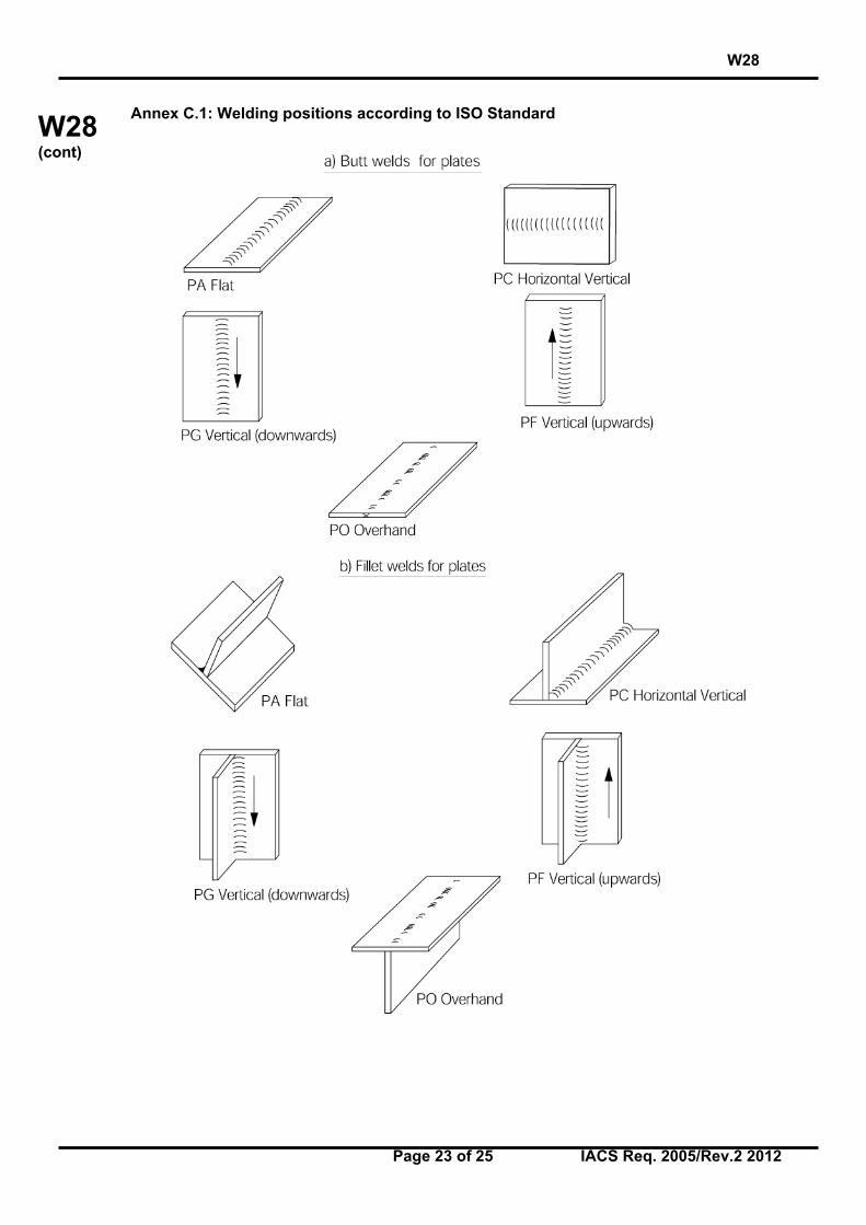
5.4 Welding position
Approval for a test made in any position is restricted to that position (see Annex C). To qualifya range of positions, test assemblies are to be welded for highest heat input position andlowest heat input position and all applicable tests are to be made on those assemblies.
5.5 Welding process
5.5.1 The approval is only valid for the welding process(es) used in the welding proceduretest. It is not permitted to change from a multi-run to a single run.
5.5.2 For multi-process procedures the welding procedure approval may be carried out withseparate welding procedure tests for each welding process. It is also possible to make thewelding procedure test as a multi-process procedure test. The approval of such a test is onlyvalid for the process sequence carried out during the multi-process procedure test.
5.6 Welding consumable
Except high heat input processes over 50kJ/cm, welding consumables cover other approvedwelding consumables having the same grade mark including all suffixes specified in UR W17and UR W23 with the welding consumable tested.
5.7 Heat input
5.7.1 The upper limit of heat input approved is 25% greater than that used in welding the testpiece or 55kJ/cm whichever is smaller, except that the upper limit is 10% greater than that forhigh heat input processes over 50kJ/cm.
W28
Page 13 of 25 IACS Req. 2005/Rev.2 2012
W28(cont)
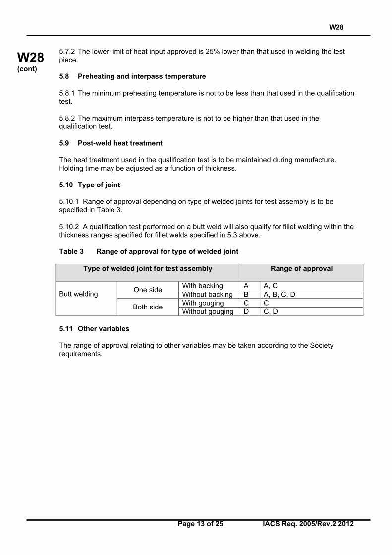
5.7.2 The lower limit of heat input approved is 25% lower than that used in welding the testpiece.
5.8 Preheating and interpass temperature
5.8.1 The minimum preheating temperature is not to be less than that used in the qualificationtest.
5.8.2 The maximum interpass temperature is not to be higher than that used in thequalification test.
5.9 Post-weld heat treatment
The heat treatment used in the qualification test is to be maintained during manufacture.Holding time may be adjusted as a function of thickness.
5.10 Type of joint
5.10.1 Range of approval depending on type of welded joints for test assembly is to bespecified in Table 3.
5.10.2 A qualification test performed on a butt weld will also qualify for fillet welding within thethickness ranges specified for fillet welds specified in 5.3 above.
Table 3 Range of approval for type of welded joint
Type of welded joint for test assembly Range of approval
With backing A A, COne side
Without backing B A, B, C, DWith gouging C C
Butt welding
Both sideWithout gouging D C, D
5.11 Other variables
The range of approval relating to other variables may be taken according to the Societyrequirements.
W28
Page 14 of 25 IACS Req. 2005/Rev.2 2012
W28(cont)
Annex A
Location of Charpy V-notch impact test
W28
Page 15 of 25 IACS Req. 2005/Rev.2 2012
W28(cont)
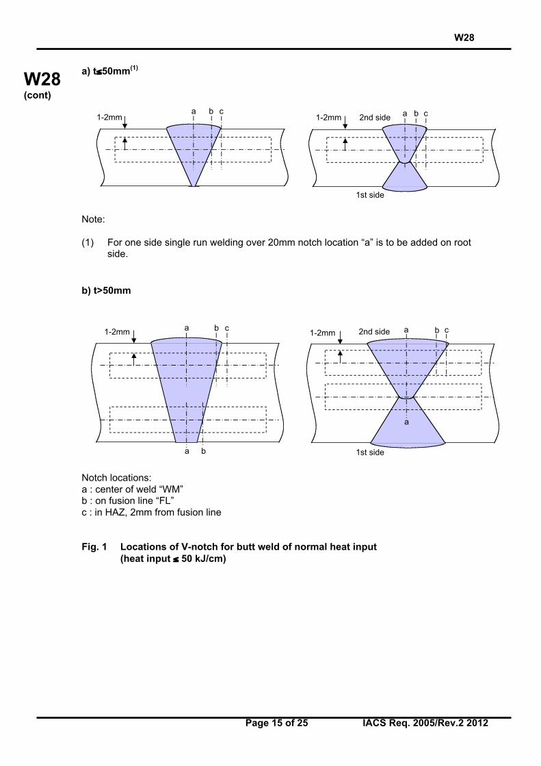
a) t≤50mm(1)
Note:
(1) For one side single run welding over 20mm notch location “a” is to be added on rootside.
b) t>50mm
Notch locations:a : center of weld “WM”b : on fusion line “FL”c : in HAZ, 2mm from fusion line
Fig. 1 Locations of V-notch for butt weld of normal heat input(heat input ≤ 50 kJ/cm)
1-2mma b c
1-2mm a2nd side
1st side
b c
a b
1-2mm a b c1-2mm a b c2nd side
1st side
a
W28
Page 16 of 25 IACS Req. 2005/Rev.2 2012
W28(cont)
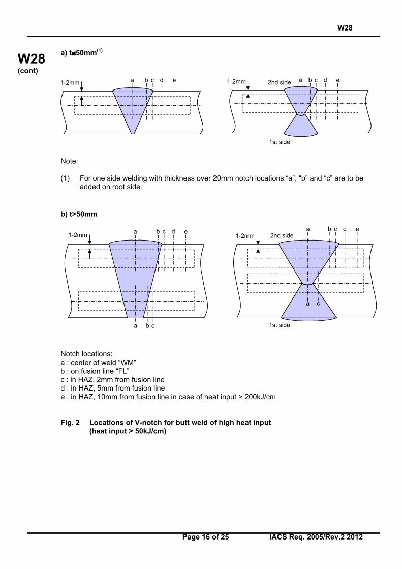
a) t≤50mm(1)
Note:
(1) For one side welding with thickness over 20mm notch locations “a”, “b” and “c” are to beadded on root side.
b) t>50mm
Notch locations:a : center of weld “WM”b : on fusion line “FL”c : in HAZ, 2mm from fusion lined : in HAZ, 5mm from fusion linee : in HAZ, 10mm from fusion line in case of heat input > 200kJ/cm
Fig. 2 Locations of V-notch for butt weld of high heat input(heat input > 50kJ/cm)
1-2mm a b c d e 1-2mm 2nd side
1st side
a b c d e
1-2mma
a b
c
c
b d e1-2mm
a2nd side
1st side
a c
cb d e
W28
Page 17 of 25 IACS Req. 2005/Rev.2 2012
W28(cont)
Annex B
Hardness test
(Typical examples of hardness test)
W28
Page 18 of 25 IACS Req. 2005/Rev.2 2012
W28(cont)
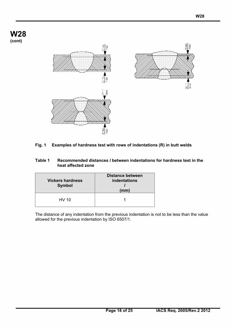
Fig. 1 Examples of hardness test with rows of indentations (R) in butt welds
Table 1 Recommended distances l between indentations for hardness test in theheat affected zone
Vickers hardnessSymbol
Distance betweenindentations
l(mm)
HV 10 1
The distance of any indentation from the previous indentation is not to be less than the valueallowed for the previous indentation by ISO 6507/1.
W28
Page 19 of 25 IACS Req. 2005/Rev.2 2012
W28(cont)
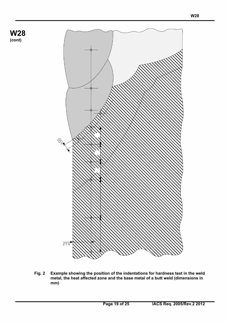
Fig. 2 Example showing the position of the indentations for hardness test in the weldmetal, the heat affected zone and the base metal of a butt weld (dimensions inmm)
ll
l
W28
Page 20 of 25 IACS Req. 2005/Rev.2 2012
W28(cont)
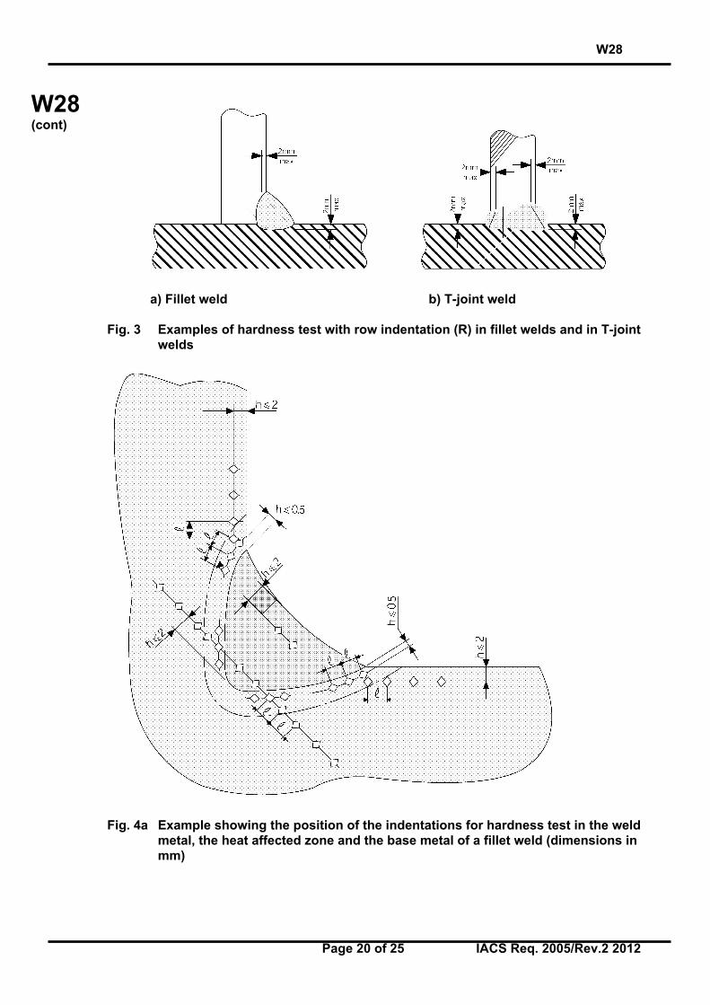
a) Fillet weld b) T-joint weld
Fig. 3 Examples of hardness test with row indentation (R) in fillet welds and in T-jointwelds
Fig. 4a Example showing the position of the indentations for hardness test in the weldmetal, the heat affected zone and the base metal of a fillet weld (dimensions inmm)
W28
Page 21 of 25 IACS Req. 2005/Rev.2 2012
W28(cont)
Fig. 4b Example showing the position of the indentations for hardness test on theweld metal, the heat affect zone and the base metal of a T-joint weld(dimensions in mm)
W28
Page 22 of 25 IACS Req. 2005/Rev.2 2012
W28(cont)
Annex C
Welding positions
W28
Page 23 of 25 IACS Req. 2005/Rev.2 2012
W28(cont)
Annex C.1: Welding positions according to ISO Standard
W28
Page 24 of 25 IACS Req. 2005/Rev.2 2012
W28(cont)
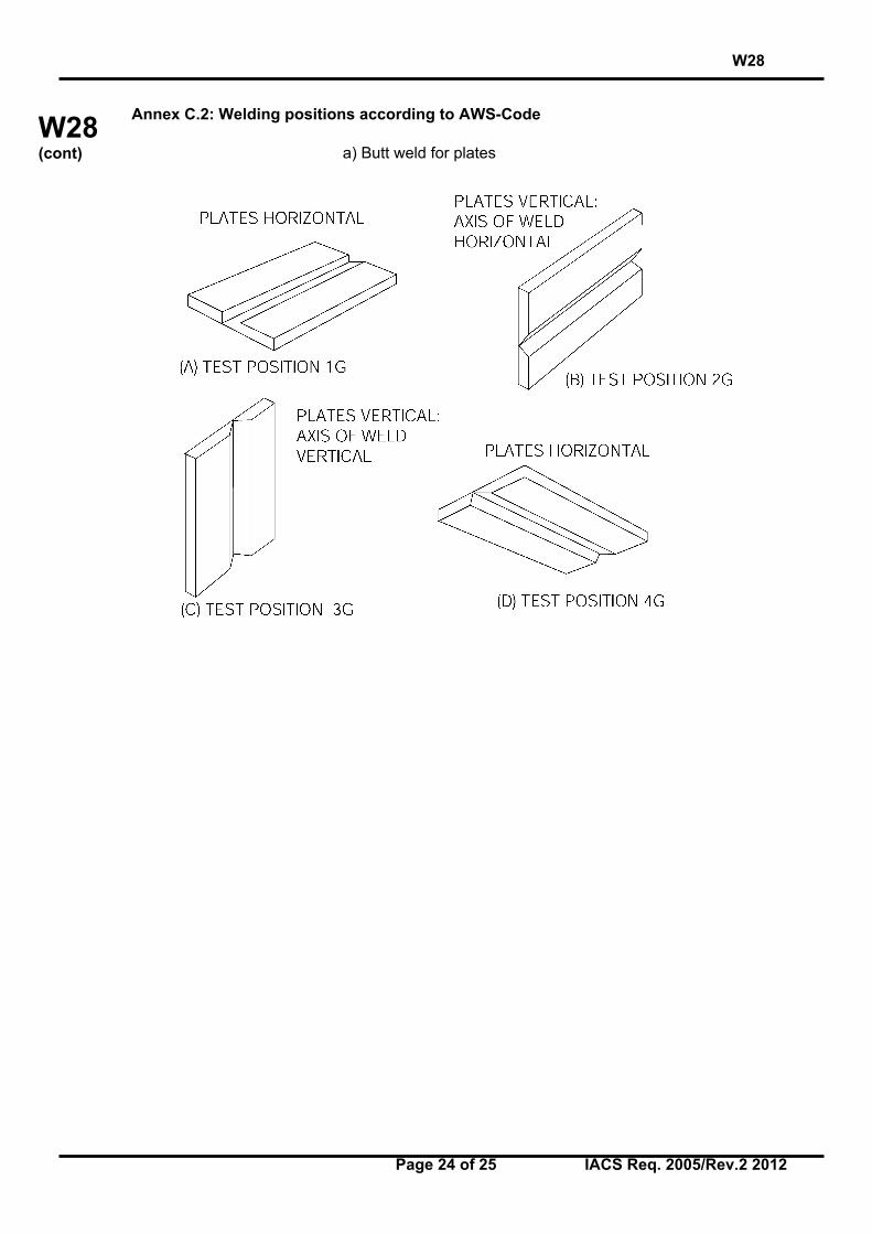
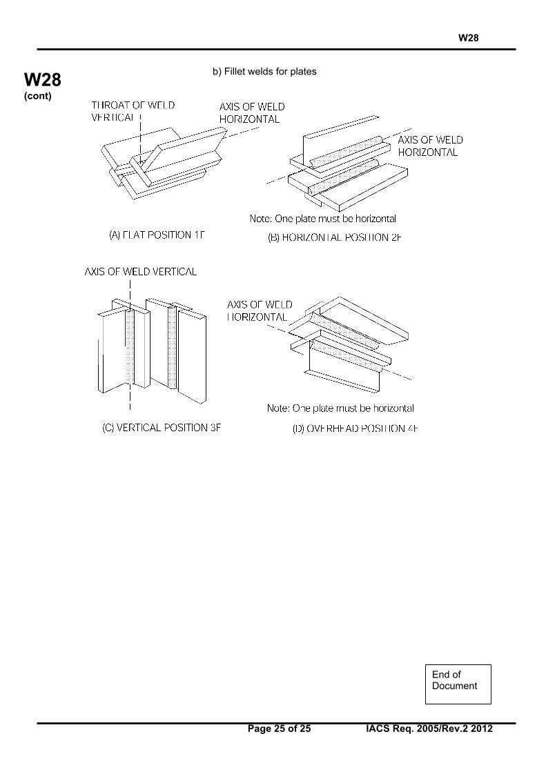
Annex C.2: Welding positions according to AWS-Code
a) Butt weld for plates
W28
Page 25 of 25 IACS Req. 2005/Rev.2 2012
W28(cont)
b) Fillet welds for plates
End ofDocument