welding — arc stud welding of metallic materialsbetawelding.ir/en/images/iso_14555.pdf · welding...
TRANSCRIPT
Reference numberISO 14555:2006(E)
© ISO 2006
INTERNATIONAL STANDARD
ISO14555
Second edition2006-10-01
Welding — Arc stud welding of metallic materials
Soudage — Soudage à l'arc des goujons sur les matériaux métalliques
For Standardization use ONLYOrder # NUMBER:129169 Downloaded:2010-01-25
Ordered by Mec.Dpt.Derayati
ISO 14555:2006(E)
PDF disclaimer This PDF file may contain embedded typefaces. In accordance with Adobe's licensing policy, this file may be printed or viewed but shall not be edited unless the typefaces which are embedded are licensed to and installed on the computer performing the editing. In downloading this file, parties accept therein the responsibility of not infringing Adobe's licensing policy. The ISO Central Secretariat accepts no liability in this area.
Adobe is a trademark of Adobe Systems Incorporated.
Details of the software products used to create this PDF file can be found in the General Info relative to the file; the PDF-creation parameters were optimized for printing. Every care has been taken to ensure that the file is suitable for use by ISO member bodies. In the unlikely event that a problem relating to it is found, please inform the Central Secretariat at the address given below.
© ISO 2006 All rights reserved. Unless otherwise specified, no part of this publication may be reproduced or utilized in any form or by any means, electronic or mechanical, including photocopying and microfilm, without permission in writing from either ISO at the address below or ISO's member body in the country of the requester.
ISO copyright office Case postale 56 • CH-1211 Geneva 20 Tel. + 41 22 749 01 11 Fax + 41 22 749 09 47 E-mail [email protected] Web www.iso.org
Published in Switzerland
ii © ISO 2006 – All rights reserved
For Standardization use ONLYOrder # NUMBER:129169 Downloaded:2010-01-25
Ordered by Mec.Dpt.Derayati
ISO 14555:2006(E)
© ISO 2006 – All rights reserved iii
Contents Page
Foreword............................................................................................................................................................. v Introduction ....................................................................................................................................................... vi 1 Scope ..................................................................................................................................................... 1 2 Normative references ........................................................................................................................... 1 3 Terms and definitions........................................................................................................................... 2 4 Symbols and abbreviated terms ......................................................................................................... 4 4.1 Symbols ................................................................................................................................................. 4 4.2 Abbreviated terms ................................................................................................................................ 4 5 Technical review ................................................................................................................................... 5 6 Welding personnel................................................................................................................................ 5 6.1 Stud-welding operators........................................................................................................................ 5 6.2 Welding coordination ........................................................................................................................... 5 7 Equipment ............................................................................................................................................. 6 7.1 Production equipment.......................................................................................................................... 6 7.2 Description of the equipment .............................................................................................................. 6 7.3 Maintenance .......................................................................................................................................... 6 8 Production planning ............................................................................................................................. 7 9 Welding procedure specification (WPS)............................................................................................. 7 9.1 General................................................................................................................................................... 7 9.2 Information related to the manufacturer ............................................................................................ 7 9.3 Information related to the parent material ......................................................................................... 7 9.4 Welding process ................................................................................................................................... 7 9.5 Joint........................................................................................................................................................ 8 9.6 Studs ...................................................................................................................................................... 8 9.7 Auxiliaries.............................................................................................................................................. 8 9.8 Power source ........................................................................................................................................ 9 9.9 Movable fixtures.................................................................................................................................... 9 9.10 Welding variables ................................................................................................................................. 9 9.11 Thermal conditions............................................................................................................................. 10 9.12 Post-weld heat-treatment ................................................................................................................... 10 9.13 Non-thermal treatment after welding................................................................................................ 10 10 Welding procedure qualification ....................................................................................................... 10 10.1 Principles............................................................................................................................................. 10 10.2 Welding procedure tests .................................................................................................................... 10 10.3 Pre-production tests........................................................................................................................... 14 10.4 Previous experience........................................................................................................................... 14 10.5 Welding procedure qualification record (WPQR) ............................................................................ 15 11 Examination and testing .................................................................................................................... 15 11.1 General................................................................................................................................................. 15 11.2 Visual examination ............................................................................................................................. 15 11.3 Bend testing ........................................................................................................................................ 15 11.4 Tensile testing..................................................................................................................................... 18 11.5 Torque test .......................................................................................................................................... 21 11.6 Macro examination ............................................................................................................................. 22 11.7 Radiographic examination................................................................................................................. 22 For Standardization use ONLY
Order # NUMBER:129169 Downloaded:2010-01-25Ordered by Mec.Dpt.Derayati
ISO 14555:2006(E)
iv © ISO 2006 – All rights reserved
12 Acceptance criteria ............................................................................................................................. 22 12.1 General ................................................................................................................................................. 22 12.2 Acceptance criteria for visual examination...................................................................................... 23 12.3 Acceptance criteria for bend testing................................................................................................. 23 12.4 Acceptance criteria for tensile testing.............................................................................................. 23 12.5 Acceptance criteria for torque testing .............................................................................................. 23 12.6 Acceptance criteria for macro examination ..................................................................................... 23 12.7 Acceptance criteria for radiographic examination .......................................................................... 23 12.8 Acceptance criteria for additional tests............................................................................................ 24 13 Workmanship....................................................................................................................................... 24 14 Process control ................................................................................................................................... 24 14.1 General ................................................................................................................................................. 24 14.2 Production test .................................................................................................................................... 25 14.3 Simplified production test.................................................................................................................. 25 14.4 Re-testing for production test or simplified production test.......................................................... 26 14.5 Production surveillance ..................................................................................................................... 26 14.6 Production surveillance record ......................................................................................................... 26 14.7 Non-conformance and corrective actions ........................................................................................ 26 14.8 Calibration of the measuring and testing equipment...................................................................... 27 Annex A (informative) Processing of stud welding....................................................................................... 28 Annex B (normative) Quality requirements for stud welding ...................................................................... 48 Annex C (informative) Manufacturer's welding procedure specification (WPS)........................................ 49 Annex D (informative) Welding procedure qualification record form (WPQR) (for drawn-arc
stud welding with ceramic ferrule or shielding gas and short-cycle drawn-arc stud welding)................................................................................................................................................ 50
Annex E (informative) Welding procedure qualification record form (WPQR) (for capacitor discharge stud welding with tip ignition and capacitor discharge drawn-arc stud welding) ..... 54
Annex F (informative) Test results — Production test (for drawn-arc stud welding with ceramic ferrule or shielding gas and short-cycle drawn-arc stud welding) ................................................ 57
Annex G (informative) Test results — Production test (for capacitor discharge stud welding with tip ignition and capacitor discharge drawn-arc stud welding)....................................................... 59
Annex H (informative) Example for production surveillance record........................................................... 61 Bibliography ..................................................................................................................................................... 62
For Standardization use ONLYOrder # NUMBER:129169 Downloaded:2010-01-25
Ordered by Mec.Dpt.Derayati
ISO 14555:2006(E)
© ISO 2006 – All rights reserved v
Foreword
ISO (the International Organization for Standardization) is a worldwide federation of national standards bodies (ISO member bodies). The work of preparing International Standards is normally carried out through ISO technical committees. Each member body interested in a subject for which a technical committee has been established has the right to be represented on that committee. International organizations, governmental and non-governmental, in liaison with ISO, also take part in the work. ISO collaborates closely with the International Electrotechnical Commission (IEC) on all matters of electrotechnical standardization.
International Standards are drafted in accordance with the rules given in the ISO/IEC Directives, Part 2.
The main task of technical committees is to prepare International Standards. Draft International Standards adopted by the technical committees are circulated to the member bodies for voting. Publication as an International Standard requires approval by at least 75 % of the member bodies casting a vote.
Attention is drawn to the possibility that some of the elements of this document may be the subject of patent rights. ISO shall not be held responsible for identifying any or all such patent rights.
ISO 14555 was prepared by Technical Committee ISO/TC 44, Welding and allied processes, Subcommittee SC 10, Unification of requirements in the field of metal welding.
This second edition cancels and replaces the first edition (ISO 14555:1998), which has been technically revised.
Requests for official interpretations of any aspect of this International Standard should be directed to the Secretariat of ISO/TC 44/SC 10 via your national standards body. A complete listing of these bodies can be found at http://www.iso.org.
For Standardization use ONLYOrder # NUMBER:129169 Downloaded:2010-01-25
Ordered by Mec.Dpt.Derayati
ISO 14555:2006(E)
vi © ISO 2006 – All rights reserved
Introduction
The purpose of arc stud welding is to weld predominantly pin-shaped metal parts to metal workpieces. In this International Standard it is referred to simply as stud welding. Amongst other things, stud welding is used in bridge building (especially in composite structures), steel structures, shipbuilding, facade-wall fabrication, vehicle manufacture, equipment design, steam-boiler construction, and the manufacture of household appliances.
The quality of a stud weld depends not only on strict compliance with the welding procedure specification but also on the correct function of the actuating mechanism (e.g. welding guns), and on the condition of the components, of the accessories and of the power supply.
This International Standard does not invalidate former specifications, providing the technical requirements are equivalent and satisfied.
For Standardization use ONLYOrder # NUMBER:129169 Downloaded:2010-01-25
Ordered by Mec.Dpt.Derayati
INTERNATIONAL STANDARD ISO 14555:2006(E)
© ISO 2006 – All rights reserved 1
Welding — Arc stud welding of metallic materials
1 Scope
This International Standard covers arc stud welding of metallic materials subject to static and dynamic loading. It specifies requirements that are particular to stud welding, in relation to welding knowledge, quality requirements, welding procedure specification, welding procedure qualification, qualification testing of operators and testing of production welds.
This International Standard is appropriate where it is necessary to demonstrate the capability of a manufacturer to produce welded construction of a specified quality.
NOTE General quality requirements for fusion welding of metallic materials are given in ISO 3834-1, ISO 3834-2, ISO 3834-3, ISO 3834-4 and ISO 3834-5.
This International Standard has been prepared in a comprehensive manner, with a view to its being used as a reference in contracts. The requirements contained within it can be adopted in full, or partially, if certain requirements are not relevant to a particular construction (see Annex B).
2 Normative references
The following referenced documents are indispensable for the application of this document. For dated references, only the edition cited applies. For undated references, the latest edition of the referenced document (including any amendments) applies.
ISO 857-1, Welding and allied processes — Vocabulary — Part 1: Metal welding processes
ISO 3834-1, Quality requirements for fusion welding of metallic materials — Part 1: Criteria for the selection of the appropriate level of quality requirements
ISO 3834-2, Quality requirements for fusion welding of metallic materials — Part 2: Comprehensive quality requirements
ISO 3834-3, Quality requirements for fusion welding of metallic materials — Part 3: Standard quality requirements
ISO 3834-4, Quality requirements for fusion welding of metallic materials — Part 4: Elementary quality requirements
ISO 4063, Welding and allied processes — Nomenclature of processes and reference numbers
ISO 6947, Welds — Working positions — Definitions of angles of slope and rotation
ISO 9606-1, Approval testing of welders — Fusion welding — Part 1: Steels
ISO 9606-2, Qualification test of welders — Fusion welding — Part 2: Aluminium and aluminium alloys
ISO 13918:—1), Welding — Studs and ceramic ferrules for arc stud welding
1) To be published. (Revision of ISO 13918:1998) For Standardization use ONLY
Order # NUMBER:129169 Downloaded:2010-01-25Ordered by Mec.Dpt.Derayati
ISO 14555:2006(E)
2 © ISO 2006 – All rights reserved
ISO 14175, Welding consumables — Shielding gases for arc welding and cutting
ISO 14731, Welding coordination — Tasks and responsibilities
ISO 14732:1998, Welding personnel — Approval testing of welding operators for fusion welding and of resistance weld setters for fully mechanized and automatic welding of metallic materials
ISO 15607:2003, Specification and qualification of welding procedures for metallic materials — General rules
ISO/TR 15608, Welding — Guidelines for a metallic materials grouping system
ISO 15611, Specification and qualification of welding procedures for metallic materials — Qualification based on previous welding experience
ISO 15613, Specification and qualification of welding procedures for metallic materials — Qualification based on pre-production welding test
ISO 15614-1:2004, Specification and qualification of welding procedures for metallic materials — Welding procedure test — Part 1: Arc and gas welding of steels and arc welding of nickel and nickel alloys
ISO 15614-2, Specification and qualification of welding procedures for metallic materials — Welding procedure test — Part 2: Arc welding of aluminium and its alloys
ISO 17636, Non-destructive testing of welds — Radiographic testing of fusion-welded joints
ISO 17662, Welding — Calibration, verification and validation of equipment used for welding, including ancillary activities
3 Terms and definitions
For the purposes of this document, the terms and definitions given in ISO 857-1, ISO 3834-1, ISO 4063, ISO 14731, ISO 14732 and ISO 15607 and the following apply.
3.1 stud fastener to be attached by stud welding
3.2 auxiliaries ceramic ferrules and shielding gases
3.3 stud-welding operator operating personnel for stud-welding equipment
NOTE In special cases (e.g. mass production at the manufacturer's factory) the welding can be carried out by suitable auxiliary personnel, appropriately trained and supervised.
3.4 stud diameter d stud nominal diameter
NOTE See ISO 13918.
3.5 welding diameter dw diameter at the weld base
For Standardization use ONLYOrder # NUMBER:129169 Downloaded:2010-01-25
Ordered by Mec.Dpt.Derayati
ISO 14555:2006(E)
© ISO 2006 – All rights reserved 3
3.6 weld zone welded area underneath the welding diameter
3.7 current intensity root-mean-square (RMS) value of the welding current in the steady state during the burning time of the arc
NOTE Current intensity is not applicable to capacitor discharge.
3.8 welding time time difference between the ignition and the final extinction of the main arc
3.9 lift L distance between the stud tip and the work piece surface with the stud-lifting mechanism in position and activated
NOTE 1 For tip ignition, this definition applies to the ignition gap.
NOTE 2 See Figure A.1.
3.10 plunge axial movement of the stud towards the surface of the work piece
3.11 protrusion P ⟨unregulated lifting mechanism⟩ distance between the tip of the stud and the face of the support device in their initial positions, where the support device faces the work piece
NOTE 1 A spring-loaded lifting mechanism is an unregulated lifting mechanism.
NOTE 2 See Figure A.1.
3.12 arc blow magnetic deflection of the arc from the axial direction of the stud
3.13 flux aluminium additive on the weld end of the stud, which improves the ignition and de-oxidizes the weld pool
3.14 dual-material stud two-material stud composed of a material at the weld tip, similar to that of the parent material, and a dissimilar material outside the weld tip, which are joined by a friction weld, thus avoiding a mixed structure in the weld zone when stud welding
3.15 structure subjected to fatigue loading structure subject to a set of typical load events described by the positions or movements of loads, their variation in intensity and their frequency and sequence of occurrence
For Standardization use ONLYOrder # NUMBER:129169 Downloaded:2010-01-25
Ordered by Mec.Dpt.Derayati
ISO 14555:2006(E)
4 © ISO 2006 – All rights reserved
4 Symbols and abbreviated terms
4.1 Symbols
For the purposes of this International Standard, the following symbols apply.
C capacitance (expressed in mF)
d stud diameter (expressed in mm)
dw welding diameter (expressed in mm)
h length of the threaded part of the nut
I current intensity (expressed in A)
L lift
P protrusion
t thickness of plate
tw welding time (expressed in ms or s)
T torque (expressed in Nm)
U charging voltage (expressed in V)
W charging energy (expressed in Ws)
a bending angle (expressed in °)
4.2 Abbreviated terms
For the purposes of this International Standard, the following abbreviated terms apply.
CF ceramic ferrule
HAZ heat-affected zone
NP no protection
PA flat welding position
PC horizontal welding position
PE overhead welding position
pWPS preliminary welding procedure specification
SG shielding gas
WPS welding procedure specification
WPQR welding procedure qualification record
For Standardization use ONLYOrder # NUMBER:129169 Downloaded:2010-01-25
Ordered by Mec.Dpt.Derayati
ISO 14555:2006(E)
© ISO 2006 – All rights reserved 5
5 Technical review
When a technical review is required by an application standard, by specification or by use of ISO 3834-2, ISO 3834-3 or ISO 3834-4, the manufacturer shall check, as appropriate, the following aspects:
a) the accessibility and welding position of the stud weld;
b) the nature of the surface and the collar shape of the welded joint;
c) materials and combinations of materials (see Tables A.3 and A.4);
d) the ratio of stud diameter to sheet metal thickness (avoidance of damage on the reverse side of the sheet);
e) dimensions and details of the weld preparation and of the finished weld, including the nature of the stud and sheet-metal surfaces, positional and angular accuracy and the length tolerance of the welded stud;
f) the use of special techniques to avoid damage to the reverse side of the sheet;
g) techniques to assure the angular position of the welded stud.
NOTE Consideration is paid to the multi-axial stress state arising from localized heating/cooling. This stress concentration reduces the dynamic strength of a component with welded studs.
6 Welding personnel
6.1 Stud-welding operators
Stud-welding operators shall be qualified in accordance with ISO 14732:1998, 4.2.1 or 4.2.2. They shall have appropriate knowledge to operate the equipment, to adjust it properly, to carry out the welding correctly and, while doing so, to pay attention to good contact and suitable connection between the work piece cables and uniform distribution of ferromagnetic materials (see Table A.8).
The qualification shall include testing in accordance with the acceptance criteria specified in 12.2.
A test of job knowledge is required for all qualification methods. This test shall cover, as a minimum:
a) setting up the welding equipment in accordance with the welding procedure specification;
b) basic knowledge of the way in which suitable connection of work piece cables, the polarity of the stud, and arc blowing can influence the weld result (see Table A.8);
c) basic assessment of the welded joint for imperfections (see Tables A.5, A.6 and A.7);
d) safe execution of the welding operations, i.e. good contact of the stud in the stud holder, no movement during the welding process, operation checking and correct positioning of the guns).
6.2 Welding coordination
Welding coordination shall be performed in accordance with ISO 14731.
Welding coordination personnel for stud welding shall have knowledge of and experience in the relevant stud-welding process, and shall be able to select and set the correct parameters, e.g. lift, protrusion (plunge), current intensity, and welding time.
A welding coordinator is not required for stud welding to structures subjected to unspecified static loading (see Annex B).
For Standardization use ONLYOrder # NUMBER:129169 Downloaded:2010-01-25
Ordered by Mec.Dpt.Derayati
ISO 14555:2006(E)
6 © ISO 2006 – All rights reserved
7 Equipment
7.1 Production equipment
Suitable stud-welding equipment shall be used, with power supplies of sufficient capacity to weld the stud properly to the parent material when the equipment is correctly set up. The following equipment shall be available, as required:
a) power sources, control unit and movable fixtures;
b) cables with sufficient cross-section, solid connection terminals and sufficient earth connection;
c) handling equipment for the technical aspects of welding fabrication (jigs, fixtures);
d) weld data monitoring equipment;
e) post-drying equipment for ceramic ferrules;
f) cleaning facilities for contact points and welding points;
g) measuring and testing equipment;
h) equipment for pre- and post-treatment;
i) equipment and welding plant for retouching.
7.2 Description of the equipment
A list of the stud-welding equipment shall be maintained, which shall serve as evidence of the performance and stud-welding application field. It shall include:
a) details of the smallest and largest weldable stud diameter;
b) the maximum number of studs to be welded per unit of time;
c) the regulating range of the power supply;
d) the mode of operation and performance of mechanized or automatic stud-welding equipment;
e) details of the available test equipment.
7.3 Maintenance
The correct functioning of the equipment shall be ensured. During production, a function check of the actuation mechanisms shall be performed at fixed intervals. Cables, terminals, stud and ceramic ferrule holders shall be regularly checked and replaced at the appropriate time. For mass production and comprehensive quality requirements in accordance with ISO 3834-2, a maintenance plan for additional essential systems shall be drawn up. Examples of such systems are:
a) stud sorting and feeding systems;
b) stud and ceramic ferrule holders;
c) mechanical guides and fixtures;
d) measuring equipment;
e) cables, hoses, connecting elements;
f) a monitoring system.
For Standardization use ONLYOrder # NUMBER:129169 Downloaded:2010-01-25
Ordered by Mec.Dpt.Derayati
ISO 14555:2006(E)
© ISO 2006 – All rights reserved 7
8 Production planning
For stud welding, the production planning shall also contain the following elements:
a) a definition of the required stud-welding procedures and equipment;
b) details of which jigs and fixtures are used;
c) the surface preparation method.
9 Welding procedure specification (WPS)
9.1 General
The welding procedure specification (WPS) shall give details of how a welding operation shall be performed and shall contain all relevant information about the welding work.
Information listed in 9.2 to 9.13 is adequate for most welding operations. For some applications, it may be necessary to supplement or reduce the list. The relevant information shall be specified in the WPS.
Ranges and tolerances shall be specified when appropriate. An example of the WPS format is given in Annex C.
9.2 Information related to the manufacturer
9.2.1 Identification of the manufacturer
⎯ unambiguous identification.
9.2.2 Identification of the WPS
⎯ alphanumeric designation (reference code).
9.2.3 Reference to the welding procedure qualification record (WPQR) or other relevant documents
⎯ alphanumeric designation (reference code).
9.3 Information related to the parent material
9.3.1 Parent material type
⎯ identification of material, preferably by reference to an appropriate standard;
⎯ parent material(s) delivery condition.
NOTE A WPS can cover a material group in accordance with ISO/TR 15608. See also ISO/TR 20172, ISO/TR 20173 and ISO/TR 20174.
9.3.2 Dimensions
⎯ the thickness or range of thickness of the parent material;
⎯ other relevant dimensions.
9.4 Welding process
⎯ designation in accordance with ISO 4063. For Standardization use ONLY
Order # NUMBER:129169 Downloaded:2010-01-25Ordered by Mec.Dpt.Derayati
ISO 14555:2006(E)
8 © ISO 2006 – All rights reserved
9.5 Joint
9.5.1 Joint design
⎯ sketch of the joint design showing the relative positions of studs and tolerances;
⎯ the sequence of the welding of studs shall be indicated on the sketch if essential for application.
9.5.2 Welding position
⎯ welding positions shall be specified in accordance with ISO 6947.
9.5.3 Preparation of parent material surface
⎯ method of surface preparation, if necessary (e.g. cleaning, degreasing, pickling);
⎯ maximum time permitted between preparation and welding (if required).
9.5.4 Jigs and fixtures
⎯ the methods to be used (if required);
⎯ fixture details, templates, etc.
9.5.5 Support
⎯ the method of support;
⎯ specification of supporting material;
⎯ dimensions of support (when welding thin plates).
9.6 Studs
9.6.1 Designation
⎯ Designation according to standard, supplier or trade name; non-standard studs shall be specified.
9.6.2 Handling
⎯ if the studs are to be treated (e.g. by cleaning) before use, this shall be specified.
9.7 Auxiliaries
9.7.1 Ceramic ferrules (if any)
⎯ designation according to standard, supplier or trade name; non-standard ceramic ferrules shall be specified;
⎯ if the ceramic ferrules are to be treated (e.g. by rebaking) before use, this shall be specified.
9.7.2 Protective gas (if any)
⎯ designation in accordance with ISO 14175. For Standardization use ONLYOrder # NUMBER:129169 Downloaded:2010-01-25
Ordered by Mec.Dpt.Derayati
ISO 14555:2006(E)
© ISO 2006 – All rights reserved 9
9.8 Power source
⎯ manufacturer, type.
9.9 Movable fixtures
9.9.1 Welding gun/head
⎯ manufacturer, type;
⎯ damper.
9.9.2 Shielding gas system (if used)
⎯ gas flow rate;
⎯ (schematic) description showing nozzle dimensions and position of nozzle(s) in relation to stud and work piece.
9.9.3 Stud feeding system (if any)
⎯ description of stud feeding system including sketch.
9.10 Welding variables
9.10.1 Drawn arc stud welding with ceramic ferrule or shielding gas and short-cycle drawn arc stud welding
a) polarity;
b) welding current;
c) welding time;
d) lift;
e) protrusion;
f) damper;
g) number and position of earth clamps.
9.10.2 Capacitor discharge drawn arc stud welding or capacitor discharge stud welding with tip ignition
a) polarity;
b) capacitance;
c) charging voltage;
d) spring force and/or gap length;
e) number and position of earth clamps;
f) welding cable configuration (if used for current control). For Standardization use ONLY
Order # NUMBER:129169 Downloaded:2010-01-25Ordered by Mec.Dpt.Derayati
ISO 14555:2006(E)
10 © ISO 2006 – All rights reserved
9.11 Thermal conditions
a) preheat temperature (if required);
b) if preheating is not required, the lowest permitted ambient temperature.
9.12 Post-weld heat-treatment
If, in special cases, any post-weld heat-treatment or ageing is necessary, specification of the procedure or reference to a separate post-weld heat-treatment or ageing specification is required. This should include specification of the entire thermal cycle.
9.13 Non-thermal treatment after welding
a) grinding, machining or any other mechanical treatment;
b) pickling or any other chemical treatment;
c) any special procedure for removal of ferrules.
10 Welding procedure qualification
10.1 Principles
Preliminary welding procedure specifications (pWPS) for arc stud welding shall be prepared in accordance with Clause 9 and qualified prior to production, whenever required. They shall specify the range for all the relevant parameters. In principle, the following methods of qualification are permitted, but specification or application code requirements can restrict the choice of method:
a) qualification by welding procedure test in accordance with 10.2;
b) qualification by pre-production tests in accordance with 10.3;
c) qualification based on previous experience in accordance with 10.4.
All new welding procedure qualifications are to be in accordance with this International Standard from the date of its issue. However, this International Standard does not invalidate previous welding procedure qualifications made to former national standards or specifications, providing the technical requirements are satisfied and the previous procedure qualifications are relevant to the application and production work on which they are to be employed. Previous procedure qualifications to former national standards or specifications should be considered at the time of the enquiry or contract stage and agreed between the contracting parties.
10.2 Welding procedure tests
10.2.1 Application
When welding procedure tests are required, these shall be carried out in accordance with the provisions in 10.2 of this International Standard, unless more severe tests are specified.
10.2.2 Proof of conformity of parent materials and stud materials
For the parent material and the stud material to be used, proof of conformity shall be available.
In the absence of such proof, the parent material and/or stud material shall be subjected to additional material tests before the welding procedure tests. For this purpose, sufficient amounts of parent material and stud material from the same melt as used in the test shall be made available.
For Standardization use ONLYOrder # NUMBER:129169 Downloaded:2010-01-25
Ordered by Mec.Dpt.Derayati
ISO 14555:2006(E)
© ISO 2006 – All rights reserved 11
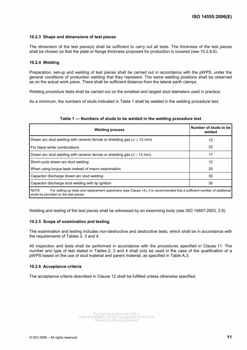
10.2.3 Shape and dimensions of test pieces
The dimension of the test piece(s) shall be sufficient to carry out all tests. The thickness of the test pieces shall be chosen so that the plate or flange thickness proposed for production is covered (see 10.2.8.6).
10.2.4 Welding
Preparation, set-up and welding of test pieces shall be carried out in accordance with the pWPS, under the general conditions of production welding that they represent. The same welding positions shall be observed as on the actual work piece. There shall be sufficient distance from the lateral earth clamps.
Welding procedure tests shall be carried out on the smallest and largest stud diameters used in practice.
As a minimum, the numbers of studs indicated in Table 1 shall be welded in the welding procedure test.
Table 1 — Numbers of studs to be welded in the welding procedure test
Welding process Number of studs to be welded
Drawn arc stud welding with ceramic ferrule or shielding gas (d u 12 mm)
For black-white combinations
12
22
Drawn arc stud welding with ceramic ferrule or shielding gas (d > 12 mm) 17
Short-cycle drawn arc stud welding
When using torque tests instead of macro examination
12
20
Capacitor discharge drawn arc stud welding 30
Capacitor discharge stud welding with tip ignition 30
NOTE For setting-up tests and replacement specimens (see Clause 14), it is recommended that a sufficient number of additional studs be provided on the test pieces.
Welding and testing of the test pieces shall be witnessed by an examining body (see ISO 15607:2003, 3.9).
10.2.5 Scope of examination and testing
The examination and testing includes non-destructive and destructive tests, which shall be in accordance with the requirements of Tables 2, 3 and 4.
All inspection and tests shall be performed in accordance with the procedures specified in Clause 11. The number and type of test stated in Tables 2, 3 and 4 shall only be used in the case of the qualification of a pWPS based on the use of stud material and parent material, as specified in Table A.3.
10.2.6 Acceptance criteria
The acceptance criteria described in Clause 12 shall be fulfilled unless otherwise specified.
For Standardization use ONLYOrder # NUMBER:129169 Downloaded:2010-01-25
Ordered by Mec.Dpt.Derayati
ISO 14555:2006(E)
12 © ISO 2006 – All rights reserved
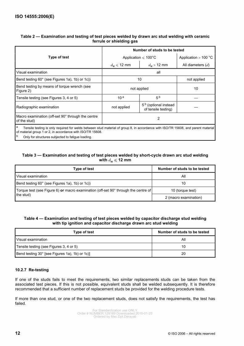
Table 2 — Examination and testing of test pieces welded by drawn arc stud welding with ceramic ferrule or shielding gas
Number of studs to be tested
Application u 100°C Application > 100 °C Type of test
dw u 12 mm dw > 12 mm All diameters (d)
Visual examination all
Bend testing 60° (see Figures 1a), 1b) or 1c)) 10 not applied
Bend testing by means of torque wrench (see Figure 2) not applied 10
Tensile testing (see Figures 3, 4 or 5) 10 a 5 b —
Radiographic examination not applied 5 b (optional instead of tensile testing) —
Macro examination (off-set 90° through the centre of the stud) 2
a Tensile testing is only required for welds between stud material of group 8, in accordance with ISO/TR 15608, and parent material of material group 1 or 2, in accordance with ISO/TR 15608. b Only for structures subjected to fatigue loading.
Table 3 — Examination and testing of test pieces welded by short-cycle drawn arc stud welding with dw u 12 mm
Type of test Number of studs to be tested
Visual examination All
Bend testing 60° (see Figures 1a), 1b) or 1c)) 10
10 (torque test) Torque test (see Figure 6) or macro examination (off-set 90° through the centre of the stud)
2 (macro examination)
Table 4 — Examination and testing of test pieces welded by capacitor discharge stud welding with tip ignition and capacitor discharge drawn arc stud welding
Type of test Number of studs to be tested
Visual examination All
Tensile testing (see Figures 3, 4 or 5) 10
Bend testing 30° [see Figures 1a), 1b) or 1c)] 20
10.2.7 Re-testing
If one of the studs fails to meet the requirements, two similar replacements studs can be taken from the associated test pieces. If this is not possible, equivalent studs shall be welded subsequently. It is therefore recommended that a sufficient number of replacement studs be provided for the welding procedure tests.
If more than one stud, or one of the two replacement studs, does not satisfy the requirements, the test has failed.
For Standardization use ONLYOrder # NUMBER:129169 Downloaded:2010-01-25
Ordered by Mec.Dpt.Derayati
ISO 14555:2006(E)
© ISO 2006 – All rights reserved 13
10.2.8 Range of qualification
10.2.8.1 General
All the conditions of validity stated below shall be met independently of each other.
Changes outside of the ranges specified shall require a new welding procedure test.
There is no limit to the duration of the validity of the welding procedure qualification, provided that no quality changes are made and that a production surveillance record is kept in accordance with 14.6.
However, since the result of stud welding depends not only on compliance with the welding procedure specification, but also, for example, on the way that the mechanical capability of the welding guns is critical in terms of weld quality, a production test shall be carried out at least once a year, as specified in 14.2.
In the event of production being suspended for more than one year, the validity of the welding procedure qualification shall be confirmed in a production test.
10.2.8.2 Conditions related to the manufacturer
The qualification of a pWPS obtained by a manufacturer is valid for welding in workshops or sites under the same technical and quality control of that manufacturer.
10.2.8.3 Conditions related to the welding process
The qualification is valid only for the welding process used in welding procedure test.
10.2.8.4 Conditions related to the parent material
A welding procedure test carried out with one of the steels of a material group, in accordance with ISO/TR 15608, covers the steels with lower specified yield strength of this material group, or the lower alloyed steels of the same material group for the intentional added elements, but not for fortuitous impurities. In accordance with ISO/TR 15608, material group 3 covers material group 1 and material group 2, whilst material group 21 covers material group 22, and vice versa.
10.2.8.5 Stud material
Welding procedure tests cover all materials of the same material group in accordance with ISO/TR 15608 with the following addition:
a) For drawn-arc stud-welding processes up to 13 mm diameter, material groups 8 and 10 cover material groups 1 and 2.1 and vice versa.
b) For capacitor discharge stud-welding processes, material group 8 covers material groups 1 to 6 and 11.1 and vice versa.
c) Material group 21 covers material group 22 and vice versa.
10.2.8.6 Parent material thickness
As recommended in Table A.1, the material thickness used for the welding procedure test applies to all thicknesses which exceed those specified in Table A.1, providing the pWPS used in the welding procedure test applies.
For material thicknesses below the recommended minimum thickness, a new welding procedure test is required. For Standardization use ONLY
Order # NUMBER:129169 Downloaded:2010-01-25Ordered by Mec.Dpt.Derayati
ISO 14555:2006(E)
14 © ISO 2006 – All rights reserved
10.2.8.7 Conditions related to the stud diameter and shape
A single welding procedure test covers all stud shapes, but only the diameters used in the test.
Two welding procedure tests on different diameter studs cover the range between the two diameters and all stud shapes.
10.2.8.8 Conditions related to the welding position
Using drawn arc stud welding with ceramic ferrule or shielding gas and short-cycle drawn arc stud welding, welding position PC covers welding positions PE and PA, but not vice versa. For welding position PC, special ceramic ferrules can be used. Welding position PE covers welding position PA, but not vice versa.
Using capacitor discharge stud welding with tip ignition and capacitor discharge drawn arc stud welding, a welding procedure test carried out in any one welding position is valid for welding in all welding positions.
10.2.8.9 Conditions related to the welding equipment
If there is a change in the type of welding gun or head, and/or power source, or welding equipment manufacturer, the welding procedure specification shall be verified by a production test.
10.2.8.10 Preheating
Welding procedure specifications that have been qualified by a welding procedure test without preheating are also valid for those for welding with preheating, but not vice versa.
10.3 Pre-production tests
The general provisions of ISO 15613 shall be adhered to, with the following additions and modifications:
a) welding procedure specifications, pWPS and WPS, shall conform to the provisions of Clause 9;
b) the actual production shall be controlled by a suitable scheme for process control;
c) the number of studs (produced items) tested shall meet the requirements of 10.2.4, if possible;
d) qualification is limited to the same type of equipment, the same type and thickness of the parent material and the same diameter of studs as used during the pre-production test.
10.4 Previous experience
The general provisions of ISO 15611 shall be adhered to, with the following additions and modifications:
a) welding procedure specifications, pWPS and WPS, shall conform to the provisions of Clause 9;
b) the former production on which the experience is based shall have been controlled by a suitable scheme for process control, giving a statistical confidence compatible with the future application of the welding procedure to be qualified;
c) qualification is limited to the same type of equipment, the same type and thickness of the parent material and the same diameter of studs as used during the production on which the experience is based.
The use of previous experience instead of welding procedure tests is not permitted for steel welds with standard or comprehensive quality requirements (see Annex A).
For Standardization use ONLYOrder # NUMBER:129169 Downloaded:2010-01-25
Ordered by Mec.Dpt.Derayati
ISO 14555:2006(E)
© ISO 2006 – All rights reserved 15
10.5 Welding procedure qualification record (WPQR)
The welding procedure qualification record (WPQR) is a statement of the results of assessing each test piece, including re-tests. The relevant items listed for the WPS in Clause 9 shall be included, together with details of any features that would be rejected on the basis of the requirements in Clause 11. If no rejectable features or unacceptable test results are found, a WPQR detailing the welding procedure test piece results is qualified, and shall be signed and dated by the examiner or test body.
A WPQR format, as shown in Annex D or Annex E, may be used to record details for the welding procedure and the test results, in order to facilitate uniform presentation and assessment of the data.
11 Examination and testing
11.1 General
The methods described in 11.2 to 11.7 may be used for examination and testing of stud welds. Tests shall be selected according to the application.
In certain stud-welding applications, e.g. steam boilers, shipbuilding or nuclear industry, additional tests (e.g. hardness tests or ultrasonic examinations) may be required by application standards or specifications.
11.2 Visual examination
For drawn arc stud welding with ceramic ferrule or shielding gas and short-cycle drawn arc stud welding, visual examination is used for assessing the following, as appropriate for the application:
a) the uniformity of the shape and the size of the collar (guidance values for drawn arc stud welding with ceramic ferrule are given in ISO 13918), and
b) location, length and angle of the stud after welding.
For capacitor discharge drawn arc stud welding and capacitor discharge stud welding with tip ignition, visual examination is used for assessing the uniformity of the spatter ring.
11.3 Bend testing
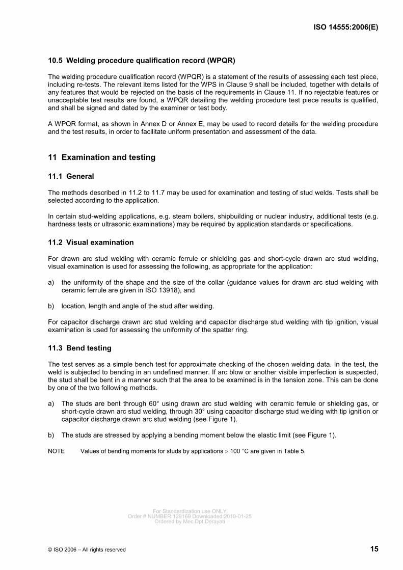
The test serves as a simple bench test for approximate checking of the chosen welding data. In the test, the weld is subjected to bending in an undefined manner. If arc blow or another visible imperfection is suspected, the stud shall be bent in a manner such that the area to be examined is in the tension zone. This can be done by one of the two following methods.
a) The studs are bent through 60° using drawn arc stud welding with ceramic ferrule or shielding gas, or short-cycle drawn arc stud welding, through 30° using capacitor discharge stud welding with tip ignition or capacitor discharge drawn arc stud welding (see Figure 1).
b) The studs are stressed by applying a bending moment below the elastic limit (see Figure 1).
NOTE Values of bending moments for studs by applications > 100 °C are given in Table 5.
For Standardization use ONLYOrder # NUMBER:129169 Downloaded:2010-01-25
Ordered by Mec.Dpt.Derayati
ISO 14555:2006(E)
16 © ISO 2006 – All rights reserved
a) b)
c)
Key 1 stud 2 work piece 3 tool α bending angle
Figure 1 — Examples for bend testing For Standardization use ONLY
Order # NUMBER:129169 Downloaded:2010-01-25Ordered by Mec.Dpt.Derayati
ISO 14555:2006(E)
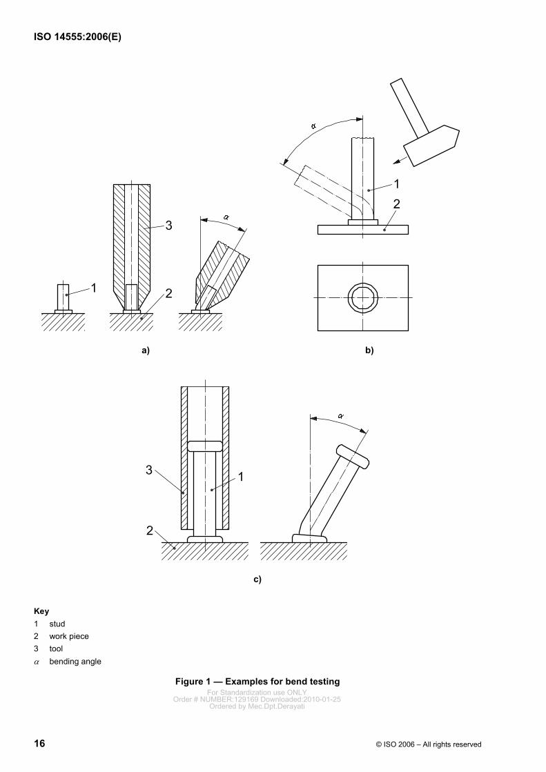
© ISO 2006 – All rights reserved 17
a) Torque wrench for bend testing
Figure 2 — Examples for bend testing by means of torque wrench
For Standardization use ONLYOrder # NUMBER:129169 Downloaded:2010-01-25
Ordered by Mec.Dpt.Derayati
ISO 14555:2006(E)
18 © ISO 2006 – All rights reserved
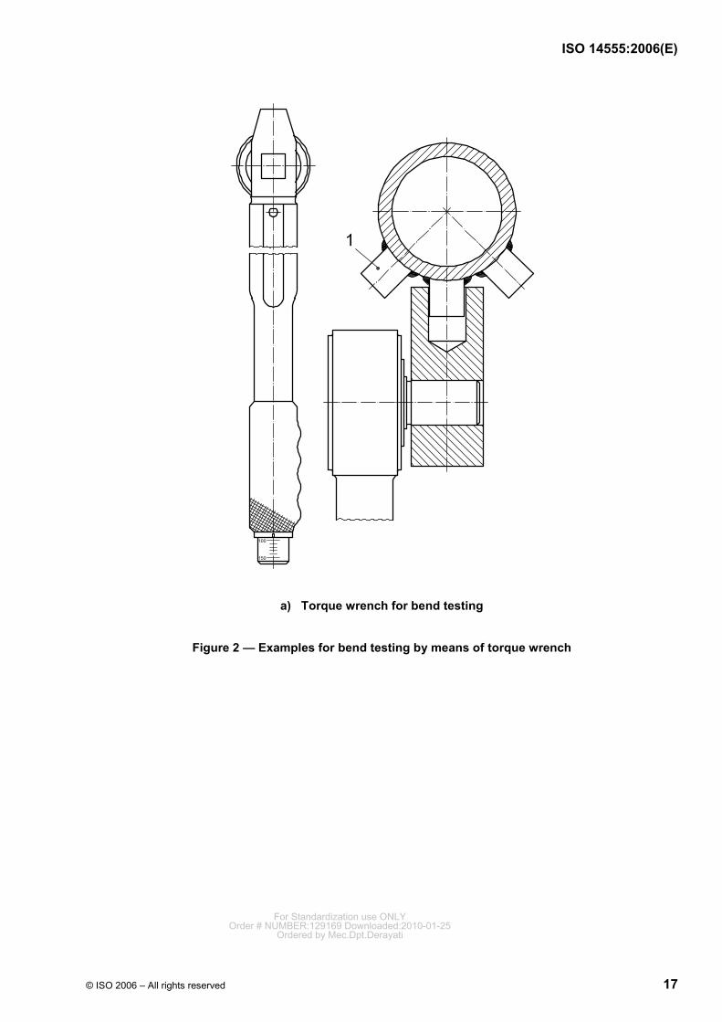
Dimensions in millimetres
b) Test tool for bend testing
Key d1 stud diameter +0,3 mm d2 tool diameter S drive dimension 1 stud
NOTE 1 The tool diameter can be chosen freely by the manufacturer, depending on the stud spacing.
NOTE 2 The drive dimension depends on the tool
Figure 2 (continued)
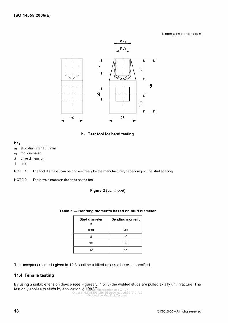
Table 5 — Bending moments based on stud diameter
Stud diameter d
mm
Bending moment
Nm
8 40
10 60
12 85
The acceptance criteria given in 12.3 shall be fulfilled unless otherwise specified.
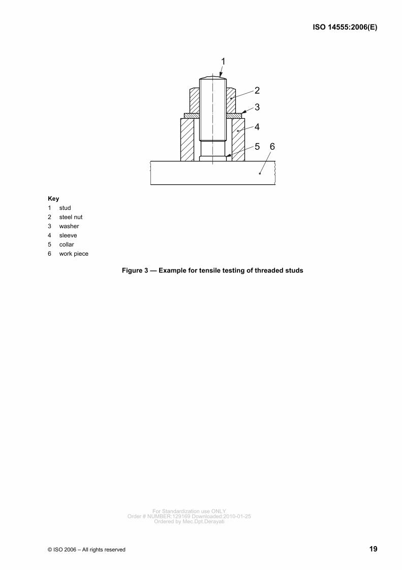
11.4 Tensile testing
By using a suitable tension device (see Figures 3, 4 or 5) the welded studs are pulled axially until fracture. The test only applies to studs by application u 100 °C. For Standardization use ONLY
Order # NUMBER:129169 Downloaded:2010-01-25Ordered by Mec.Dpt.Derayati
ISO 14555:2006(E)
© ISO 2006 – All rights reserved 19
Key 1 stud 2 steel nut 3 washer 4 sleeve 5 collar 6 work piece
Figure 3 — Example for tensile testing of threaded studs
For Standardization use ONLYOrder # NUMBER:129169 Downloaded:2010-01-25
Ordered by Mec.Dpt.Derayati
ISO 14555:2006(E)
20 © ISO 2006 – All rights reserved
a)
b)
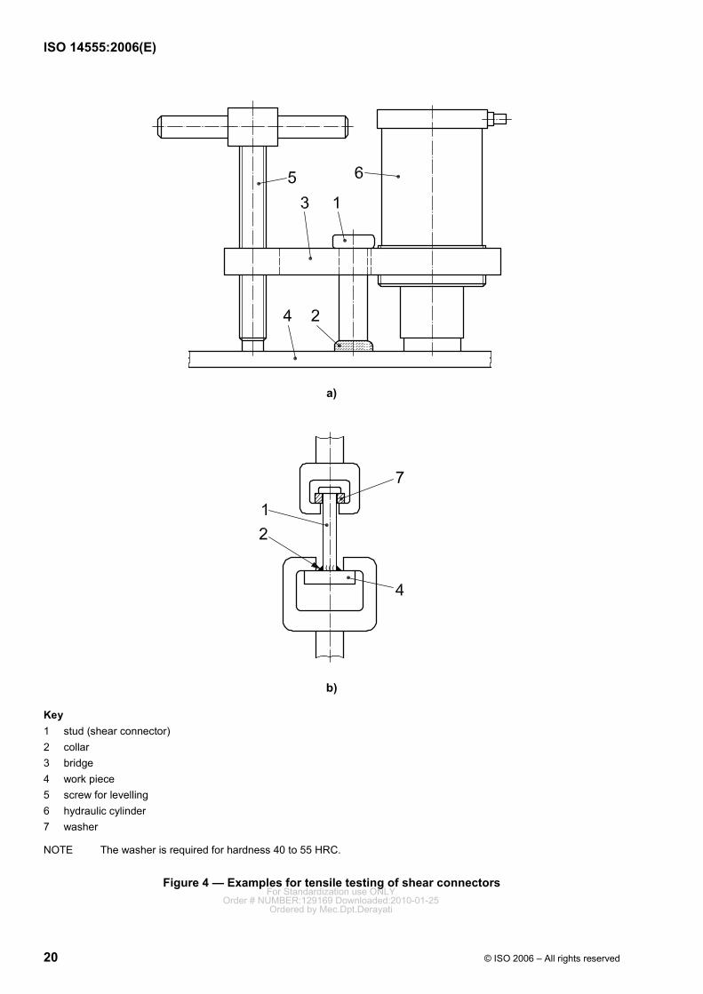
Key 1 stud (shear connector) 2 collar 3 bridge 4 work piece 5 screw for levelling 6 hydraulic cylinder 7 washer
NOTE The washer is required for hardness 40 to 55 HRC.
Figure 4 — Examples for tensile testing of shear connectors For Standardization use ONLY
Order # NUMBER:129169 Downloaded:2010-01-25Ordered by Mec.Dpt.Derayati
ISO 14555:2006(E)
© ISO 2006 – All rights reserved 21
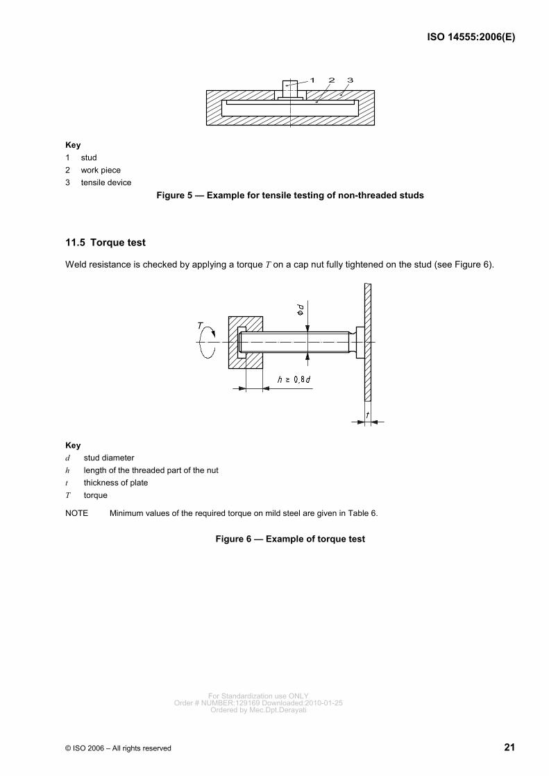
Key 1 stud 2 work piece 3 tensile device
Figure 5 — Example for tensile testing of non-threaded studs
11.5 Torque test
Weld resistance is checked by applying a torque T on a cap nut fully tightened on the stud (see Figure 6).
Key d stud diameter h length of the threaded part of the nut t thickness of plate T torque
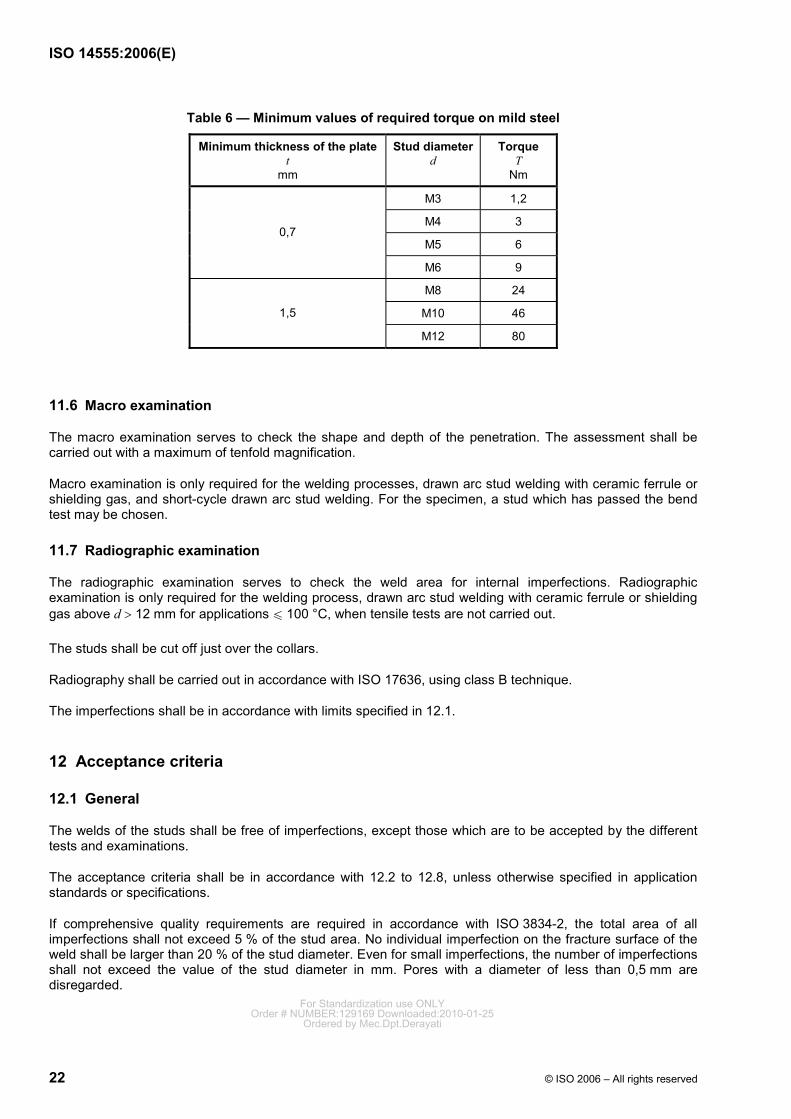
NOTE Minimum values of the required torque on mild steel are given in Table 6.
Figure 6 — Example of torque test
For Standardization use ONLYOrder # NUMBER:129169 Downloaded:2010-01-25
Ordered by Mec.Dpt.Derayati
ISO 14555:2006(E)
22 © ISO 2006 – All rights reserved
Table 6 — Minimum values of required torque on mild steel
Minimum thickness of the platet
mm
Stud diameterd
Torque T
Nm
M3 1,2
M4 3
M5 6 0,7
M6 9
M8 24
M10 46 1,5
M12 80
11.6 Macro examination
The macro examination serves to check the shape and depth of the penetration. The assessment shall be carried out with a maximum of tenfold magnification.
Macro examination is only required for the welding processes, drawn arc stud welding with ceramic ferrule or shielding gas, and short-cycle drawn arc stud welding. For the specimen, a stud which has passed the bend test may be chosen.
11.7 Radiographic examination
The radiographic examination serves to check the weld area for internal imperfections. Radiographic examination is only required for the welding process, drawn arc stud welding with ceramic ferrule or shielding gas above d > 12 mm for applications u 100 °C, when tensile tests are not carried out.
The studs shall be cut off just over the collars.
Radiography shall be carried out in accordance with ISO 17636, using class B technique.
The imperfections shall be in accordance with limits specified in 12.1.
12 Acceptance criteria
12.1 General
The welds of the studs shall be free of imperfections, except those which are to be accepted by the different tests and examinations.
The acceptance criteria shall be in accordance with 12.2 to 12.8, unless otherwise specified in application standards or specifications.
If comprehensive quality requirements are required in accordance with ISO 3834-2, the total area of all imperfections shall not exceed 5 % of the stud area. No individual imperfection on the fracture surface of the weld shall be larger than 20 % of the stud diameter. Even for small imperfections, the number of imperfections shall not exceed the value of the stud diameter in mm. Pores with a diameter of less than 0,5 mm are disregarded.
For Standardization use ONLYOrder # NUMBER:129169 Downloaded:2010-01-25
Ordered by Mec.Dpt.Derayati
ISO 14555:2006(E)
© ISO 2006 – All rights reserved 23
If standard quality requirements are required in accordance with ISO 3834-3, the total area of all imperfections shall not exceed 10 % of the stud area.
If elementary quality requirements are required in accordance with ISO 3834-4, the limit of the imperfections shall be specified.
12.2 Acceptance criteria for visual examination
For drawn arc stud welding with ceramic ferrule or shielding gas, and short-cycle drawn arc stud welding, the imperfections shown in Table A.5, Nos. 2 to 5, and the imperfections shown in Table A.6, Nos. 2 and 5, are not acceptable.
For capacitor discharge drawn arc stud welding and capacitor discharge stud welding with tip ignition, the imperfections shown in Table A.7, Nos. 2 to 4, are not acceptable.
12.3 Acceptance criteria for bend testing
A weld passes the test if no cracks are found in the weld after bending of the stud through 30° or 60°.
If a low-deformation fracture occurs in the heat-affected zone, the weldability of the materials shall be checked (e.g. tendency to hardening).
If inhomogeneous deformation has to be expected due to the geometry of the stud, e.g. for studs with reduced base, or if a bend until the mentioned angle is not possible, e.g. for studs of short length in relation to diameter, for two-material studs and for studs with yield strength above 355 N/mm2, the suitability of the weld shall be shown by other means. A sufficient plastic deformability shall be achieved.
Cracks which arise from the thread bottom are disregarded.
12.4 Acceptance criteria for tensile testing
A fracture in the weld area is not permitted, if comprehensive quality requirements in accordance with ISO 3834-2 are required.
If standard quality requirements in accordance with ISO 3834-3 are required, fractures within the weld zone are only permitted if the nominal tensile strength of the stud material is reached. Imperfections in the fracture surface shall be in accordance with the limits specified in 12.1.
By use of flanged stud and the welding processes, capacitor discharge drawn arc stud welding or capacitor discharge stud welding with tip ignition fractures within the weld zone are permitted, if the non-welded area does not exceed 35 % of the flanged area.
12.5 Acceptance criteria for torque testing
The required torque shall be reached without weld failure.
12.6 Acceptance criteria for macro examination
Imperfections with dimensions larger than specified in 12.1 are not acceptable.
In the case of applications > 100 °C, a sufficient weld between stud and tube material has to be achieved whilst leaving a minimum of 2 mm wall thickness non molten in the tube. In the case of undershooting this value, the actual conditions shall be proven by calculation.
12.7 Acceptance criteria for radiographic examination
Imperfections with dimensions larger than specified in 12.1 are not acceptable. For Standardization use ONLY
Order # NUMBER:129169 Downloaded:2010-01-25Ordered by Mec.Dpt.Derayati
ISO 14555:2006(E)
24 © ISO 2006 – All rights reserved
12.8 Acceptance criteria for additional tests
Acceptance criteria for additional tests shall be specified. For the assessment, the characteristics of the stud-welding process shall be taken into account.
EXAMPLE For the hardness test, higher hardness values than those specified in ISO 15614-1:2004, Table 2, are permitted.
13 Workmanship
Surfaces to be welded shall be maintained dry and free from condensation. When material temperatures are below 0 °C, appropriate preheating may be necessary. For reasons of weldability, the carbon content of the steels should be u 0,22 %.
Depending on the welding process, ceramic ferrules and/or shielding gases are used for protection or to concentrate the arc. The ceramic ferrules shall be correctly chosen for the stud diameter and the type of stud. The following points shall be observed:
a) the ceramic ferrules shall be stored in a dry place;
b) wet ceramic ferrules shall be rebaked at elevated temperatures before use (1 h above 900 °C);
c) the ceramic ferrule shall be pressed against the parent material;
d) the ceramic ferrule shall fit centrally with respect to the stud.
NOTE Tilting or uneven contact of the ceramic ferrule at the stud leads to an uneven collar and can inhibit plunging.
In special cases (drawn-arc stud welding of aluminium and its alloys or CrNi steels) it may be necessary to use shielding gases. In principle, the ceramic ferrule can be replaced by shielding gas (for restrictions, see Table A.1). The gas is fed to a device that shall ensure uniform gas shielding without turbulence. Note also the following points:
⎯ the gas feed should be sealed off on the stud side;
⎯ the gas shall displace the atmosphere before welding starts, so a defined pre-flow time shall be observed;
⎯ in the case of aluminium, particularly careful gas shielding is essential.
14 Process control
14.1 General
For quality assurance, various quality requirements shall be met, depending on the stud-welding process and the field of application (see Annex B). Before, during and after production, tests shall therefore be performed. The various tests are as follows:
a) production test;
b) simplified production test;
c) production surveillance.
These tests can be carried out by using the actual production pieces or by using special test pieces. The pieces shall correspond to the production conditions. For Standardization use ONLY
Order # NUMBER:129169 Downloaded:2010-01-25Ordered by Mec.Dpt.Derayati
ISO 14555:2006(E)
© ISO 2006 – All rights reserved 25
14.2 Production test
14.2.1 General
Production tests shall be performed by the manufacturer before the beginning of welding operations on a construction or a group of similar constructions, and/or after a specified number of welds. This number shall be taken from the relevant application standard or shall be laid down in the specification.
The production test is limited to the stud diameter used, the parent material and the type of equipment.
14.2.2 Production test for drawn-arc stud welding with ceramic ferrule or shielding gas and short-cycle drawn-arc stud welding
At least ten studs shall be welded. For setting-up tests and, where appropriate, replacement tests, a sufficient number of additional studs should be provided on the test piece. The following examinations and tests shall be performed:
a) visual examination (all studs);
b) bend testing (five studs);
c) macro examinations of two different studs (off-set by 90° through the centre of the stud).
NOTE For short cycle drawn-arc stud welding, macro examinations can be replaced by torque tests (five studs).
The examinations and testing are performed and evaluated in accordance with Clause 11.
The results of the production test shall be documented (see Annex F).
14.2.3 Production test for capacitor discharge stud welding with tip ignition and capacitor discharge drawn-arc stud welding
At least ten studs shall be welded. For setting-up tests and, where appropriate, replacement tests, a sufficient number of additional studs should be provided on the test piece. The following examinations and tests shall be performed:
a) visual examination (all studs);
b) tensile testing (three studs);
c) bend testing (five studs).
The examination and tests are performed and evaluated in accordance with Clause 11.
The results of the production test shall be documented (see Annex G).
14.3 Simplified production test
Simplified production tests shall be performed by the manufacturer before the start of each shift. They can also be requested after a certain number of welds, by the application standard rules or in the specification.
The purpose of the simplified production test is to check that the equipment is correctly set up, and that it is operating correctly. Three studs shall be welded. The simplified production tests comprise at least the following test and examination:
a) visual examination (all studs);
b) bend testing (all studs).
The examination and test are performed and evaluated in accordance with Clause 11.
The results of the simplified production test shall be documented. For Standardization use ONLY
Order # NUMBER:129169 Downloaded:2010-01-25Ordered by Mec.Dpt.Derayati
ISO 14555:2006(E)
26 © ISO 2006 – All rights reserved
14.4 Re-testing for production test or simplified production test
If one of the studs does not meet the requirements, two additional studs of the same type can be taken from the associated test piece. If this is not possible, similar studs shall be additionally welded.
NOTE This necessitates that a sufficient quantity of replacement specimens be provided in a production test.
If one of the additional studs does not satisfy the requirements, corrective action (see 14.7) shall be taken and the production test shall be repeated.
14.5 Production surveillance
14.5.1 Visual examination
Visual examination is generally sufficient for production surveillance and shall cover all welds.
14.5.2 Checking the welding parameters
The relevant welding parameters shall be checked regularly.
NOTE They can be monitored by suitable equipment.
14.5.3 Other non-destructive examinations and tests
If specified in the application standard, non-destructive testing may be added to production surveillance. Suitable techniques are:
a) checking the length of the studs after welding;
b) tensile test, bend test, torque test with restricted values.
14.6 Production surveillance record
The manufacturer keeps a production surveillance record, which contains the results of the production test, simplified production test and production surveillance. The manufacturer shall keep a different record for each stud-welding process and the record shall be kept available, with the results of all tests recorded. Annex H is an example form and should be used, where appropriate.
14.7 Non-conformance and corrective actions
If there is an indication of non-conforming welding, e.g. porosity, collar not complete or unequal, or if the length of one stud is outside the specification, a bend test (15°) or tensile test (limited to the design strength) shall be performed on that stud. If the stud weld fails to satisfy the requirements in this test, three welds made before and, where appropriate, after the defective weld shall also be subjected to bend or tensile testing.
If one of these studs also fails to satisfy the requirements in the test, appropriate testing shall be carried out on all studs on the same work piece.
Corrective actions shall be taken for all non-conforming stud welds, either by removal of the defective stud, where necessary, and repeat stud welding, or by repair welding with a suitable welding process. In isolated cases, stud welding processes may be replaced by other suitable welding processes. Depending on the stud diameter, a fillet weld shall reach the calculated throat.
NOTE Sometimes defective studs do not need to be removed, but can be substituted by extra studs.
Alternative welding procedures shall be qualified in accordance with ISO 15614-1 or ISO 15614-2, and welders shall be qualified in accordance with ISO 9606-1 or ISO 9606-2.
For Standardization use ONLYOrder # NUMBER:129169 Downloaded:2010-01-25
Ordered by Mec.Dpt.Derayati
ISO 14555:2006(E)
© ISO 2006 – All rights reserved 27
All repaired or replaced studs shall be tested in accordance with the specifications.
In addition, steps shall be taken to ensure that factors adversely affecting the stud welding are identified and compensated.
14.8 Calibration of the measuring and testing equipment
In the case of comprehensive quality requirements in accordance with ISO 3834-2, the manufacturer shall be responsible for the appropriate calibration of inspection, measuring and testing equipment. All equipment shall be suitably controlled and shall be calibrated at specified intervals (see ISO 17662). See also Annex B.
NOTE In the case of drawn-arc stud-welding processes, this applies particularly to current intensity and welding time measurement.
For Standardization use ONLYOrder # NUMBER:129169 Downloaded:2010-01-25
Ordered by Mec.Dpt.Derayati
ISO 14555:2006(E)
28 © ISO 2006 – All rights reserved
Annex A (informative)
Processing of stud welding
A.1 General
This annex gives general guidance for the satisfactory production and control of stud welding.
In stud welding, an arc is briefly struck between the face of the stud and the work piece; both parts start to melt and are then joined. Depending on the nature of the ignition method, a distinction is made between drawn-arc stud welding and stud welding with tip ignition. Each method requires suitable power supplies, actuating devices, studs and accessories (e.g. ceramic ferrules). A feature of stud welding is the very short arc burn time (approximately 0,5 ms to 3 000 ms) and the associated high rate of heating and cooling. Normally the diameter of the stud can range up to 10 mm for tip ignition welding, and up to 25 mm for drawn-arc welding.
A.2 Welding processes
A.2.1 Drawn arc stud welding
A.2.1.1 General
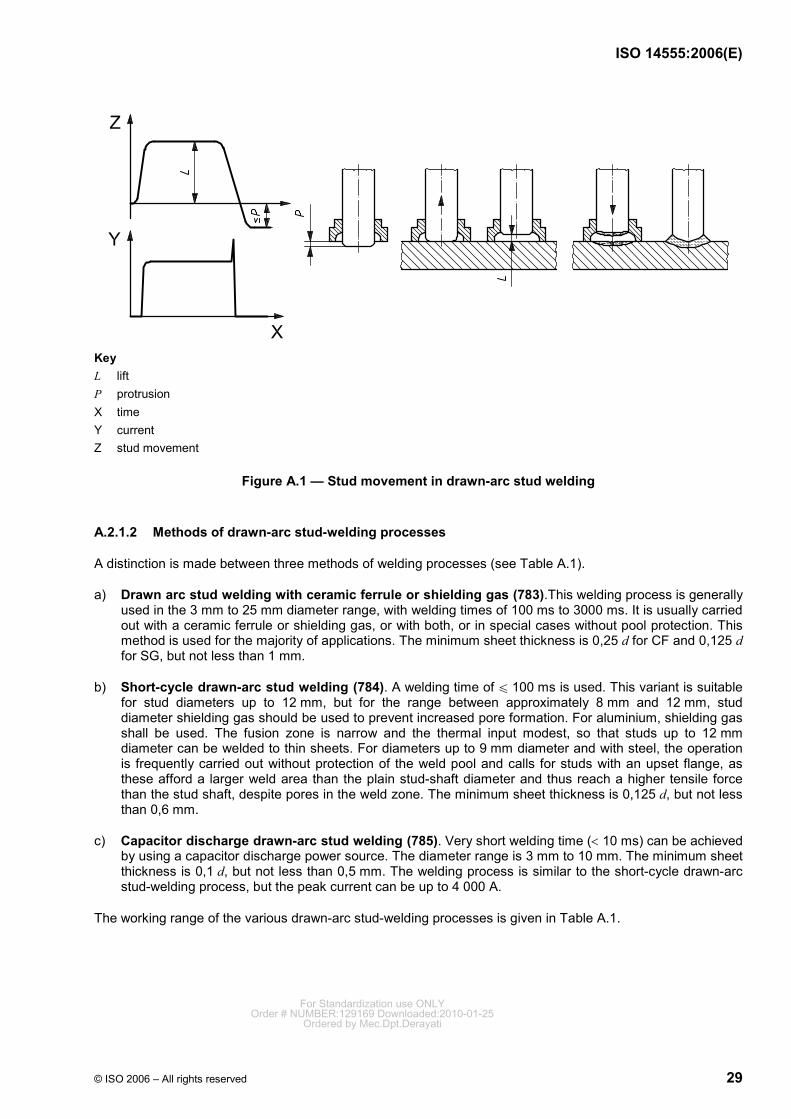
Drawn arc stud welding can be done mechanically or automatically, using welding guns or welding heads. The stud is inserted into the stud holder and - fitted with a ceramic ferrule, if necessary - applied to the work piece. At the beginning of the welding process, the stud is lifted by the mechanism and, normally, first a pilot arc, then the main arc, are struck between the tip of the stud and the work piece. This causes the face of the stud and the parent material to melt. When the welding time has elapsed, the stud is plunged with little force (< 100 N) into the molten pool, and the current source is switched off. The ceramic ferrule is then removed. Figure A.1 shows the sequence of events using a ceramic ferrule.
For Standardization use ONLYOrder # NUMBER:129169 Downloaded:2010-01-25
Ordered by Mec.Dpt.Derayati
ISO 14555:2006(E)
© ISO 2006 – All rights reserved 29
Key L lift P protrusion X time Y current Z stud movement
Figure A.1 — Stud movement in drawn-arc stud welding
A.2.1.2 Methods of drawn-arc stud-welding processes
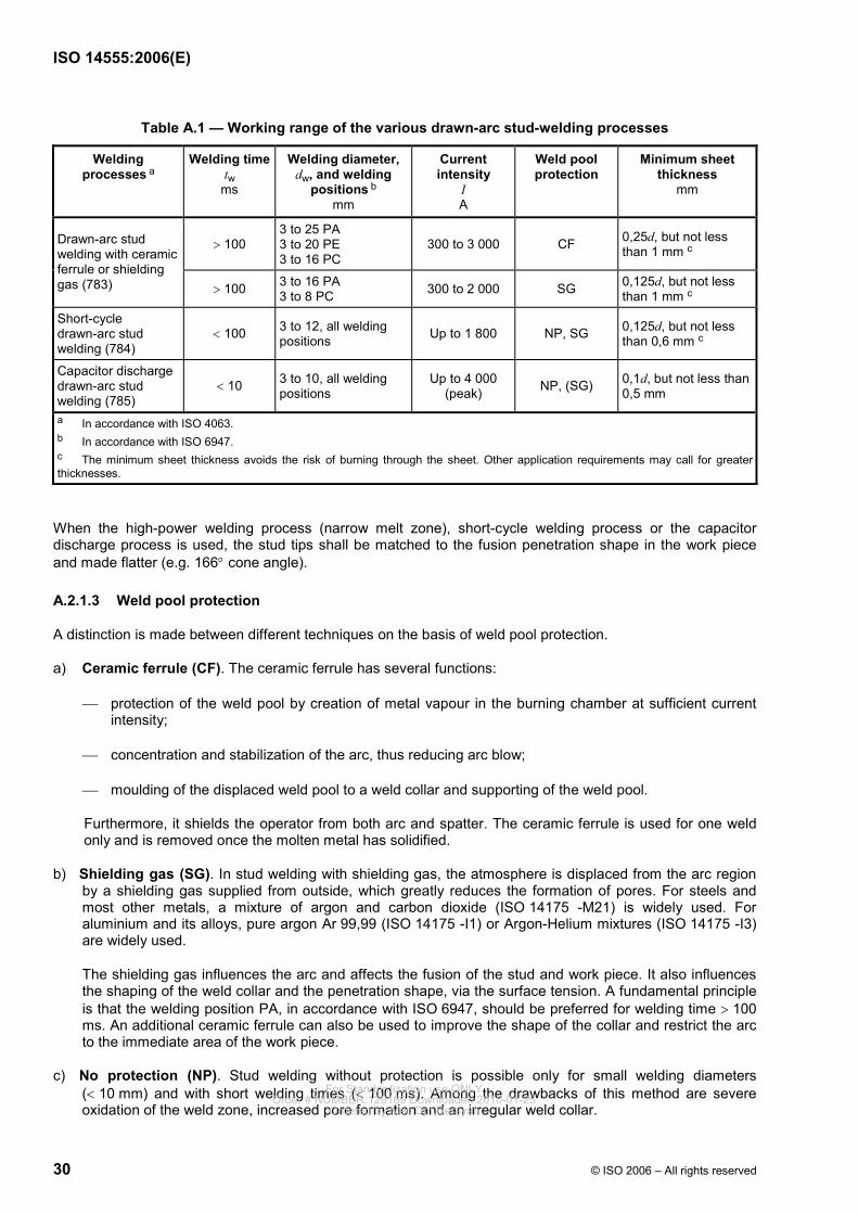
A distinction is made between three methods of welding processes (see Table A.1).
a) Drawn arc stud welding with ceramic ferrule or shielding gas (783).This welding process is generally used in the 3 mm to 25 mm diameter range, with welding times of 100 ms to 3000 ms. It is usually carried out with a ceramic ferrule or shielding gas, or with both, or in special cases without pool protection. This method is used for the majority of applications. The minimum sheet thickness is 0,25 d for CF and 0,125 d for SG, but not less than 1 mm.
b) Short-cycle drawn-arc stud welding (784). A welding time of u 100 ms is used. This variant is suitable for stud diameters up to 12 mm, but for the range between approximately 8 mm and 12 mm, stud diameter shielding gas should be used to prevent increased pore formation. For aluminium, shielding gas shall be used. The fusion zone is narrow and the thermal input modest, so that studs up to 12 mm diameter can be welded to thin sheets. For diameters up to 9 mm diameter and with steel, the operation is frequently carried out without protection of the weld pool and calls for studs with an upset flange, as these afford a larger weld area than the plain stud-shaft diameter and thus reach a higher tensile force than the stud shaft, despite pores in the weld zone. The minimum sheet thickness is 0,125 d, but not less than 0,6 mm.
c) Capacitor discharge drawn-arc stud welding (785). Very short welding time (< 10 ms) can be achieved by using a capacitor discharge power source. The diameter range is 3 mm to 10 mm. The minimum sheet thickness is 0,1 d, but not less than 0,5 mm. The welding process is similar to the short-cycle drawn-arc stud-welding process, but the peak current can be up to 4 000 A.
The working range of the various drawn-arc stud-welding processes is given in Table A.1.
For Standardization use ONLYOrder # NUMBER:129169 Downloaded:2010-01-25
Ordered by Mec.Dpt.Derayati
ISO 14555:2006(E)
30 © ISO 2006 – All rights reserved
Table A.1 — Working range of the various drawn-arc stud-welding processes
Welding processes a
Welding timetw ms
Welding diameter, dw, and welding
positions b
mm
Current intensity
I A
Weld pool protection
Minimum sheet thickness
mm
> 100 3 to 25 PA 3 to 20 PE 3 to 16 PC
300 to 3 000 CF 0,25d, but not less than 1 mm c
Drawn-arc stud welding with ceramic ferrule or shielding gas (783) > 100 3 to 16 PA
3 to 8 PC 300 to 2 000 SG 0,125d, but not less than 1 mm c
Short-cycle drawn-arc stud welding (784)
< 100 3 to 12, all welding positions Up to 1 800 NP, SG 0,125d, but not less
than 0,6 mm c
Capacitor discharge drawn-arc stud welding (785)
< 10 3 to 10, all welding positions
Up to 4 000 (peak) NP, (SG) 0,1d, but not less than
0,5 mm
a In accordance with ISO 4063. b In accordance with ISO 6947. c The minimum sheet thickness avoids the risk of burning through the sheet. Other application requirements may call for greater thicknesses.
When the high-power welding process (narrow melt zone), short-cycle welding process or the capacitor discharge process is used, the stud tips shall be matched to the fusion penetration shape in the work piece and made flatter (e.g. 166° cone angle).
A.2.1.3 Weld pool protection
A distinction is made between different techniques on the basis of weld pool protection.
a) Ceramic ferrule (CF). The ceramic ferrule has several functions:
⎯ protection of the weld pool by creation of metal vapour in the burning chamber at sufficient current intensity;
⎯ concentration and stabilization of the arc, thus reducing arc blow;
⎯ moulding of the displaced weld pool to a weld collar and supporting of the weld pool.
Furthermore, it shields the operator from both arc and spatter. The ceramic ferrule is used for one weld only and is removed once the molten metal has solidified.
b) Shielding gas (SG). In stud welding with shielding gas, the atmosphere is displaced from the arc region by a shielding gas supplied from outside, which greatly reduces the formation of pores. For steels and most other metals, a mixture of argon and carbon dioxide (ISO 14175 -M21) is widely used. For aluminium and its alloys, pure argon Ar 99,99 (ISO 14175 -I1) or Argon-Helium mixtures (ISO 14175 -I3) are widely used.
The shielding gas influences the arc and affects the fusion of the stud and work piece. It also influences the shaping of the weld collar and the penetration shape, via the surface tension. A fundamental principle is that the welding position PA, in accordance with ISO 6947, should be preferred for welding time > 100 ms. An additional ceramic ferrule can also be used to improve the shape of the collar and restrict the arc to the immediate area of the work piece.
c) No protection (NP). Stud welding without protection is possible only for small welding diameters (< 10 mm) and with short welding times (< 100 ms). Among the drawbacks of this method are severe oxidation of the weld zone, increased pore formation and an irregular weld collar.
For Standardization use ONLYOrder # NUMBER:129169 Downloaded:2010-01-25
Ordered by Mec.Dpt.Derayati
ISO 14555:2006(E)
© ISO 2006 – All rights reserved 31
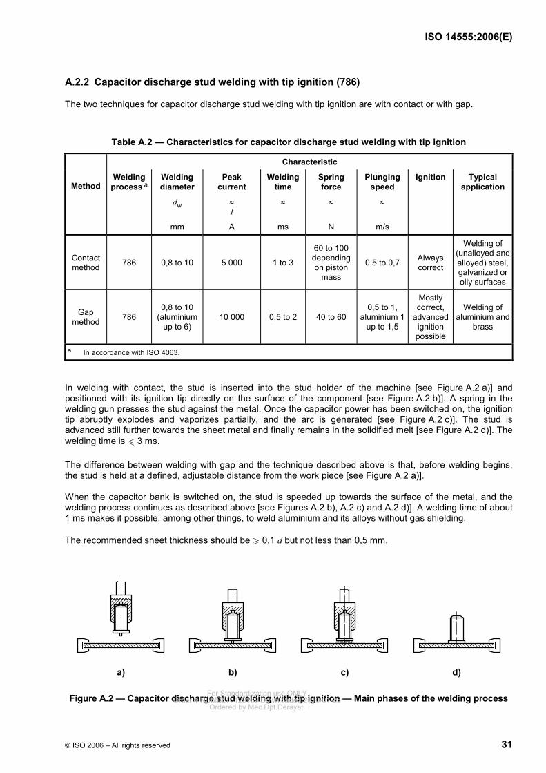
A.2.2 Capacitor discharge stud welding with tip ignition (786)
The two techniques for capacitor discharge stud welding with tip ignition are with contact or with gap.
Table A.2 — Characteristics for capacitor discharge stud welding with tip ignition
Characteristic
Method Welding
process a Welding diameter
dw
Peak current
≈ I
Welding time
≈
Spring force
≈
Plunging speed
≈
Ignition Typical application
mm A ms N m/s
Contact method 786 0,8 to 10 5 000 1 to 3
60 to 100 depending on piston
mass
0,5 to 0,7 Always correct
Welding of (unalloyed and alloyed) steel, galvanized or oily surfaces
Gap method 786
0,8 to 10 (aluminium
up to 6) 10 000 0,5 to 2 40 to 60
0,5 to 1, aluminium 1
up to 1,5
Mostly correct,
advanced ignition possible
Welding of aluminium and
brass
a In accordance with ISO 4063.
In welding with contact, the stud is inserted into the stud holder of the machine [see Figure A.2 a)] and positioned with its ignition tip directly on the surface of the component [see Figure A.2 b)]. A spring in the welding gun presses the stud against the metal. Once the capacitor power has been switched on, the ignition tip abruptly explodes and vaporizes partially, and the arc is generated [see Figure A.2 c)]. The stud is advanced still further towards the sheet metal and finally remains in the solidified melt [see Figure A.2 d)]. The welding time is u 3 ms.
The difference between welding with gap and the technique described above is that, before welding begins, the stud is held at a defined, adjustable distance from the work piece [see Figure A.2 a)].
When the capacitor bank is switched on, the stud is speeded up towards the surface of the metal, and the welding process continues as described above [see Figures A.2 b), A.2 c) and A.2 d)]. A welding time of about 1 ms makes it possible, among other things, to weld aluminium and its alloys without gas shielding.
The recommended sheet thickness should be W 0,1 d but not less than 0,5 mm.
a) b) c) d)
Figure A.2 — Capacitor discharge stud welding with tip ignition — Main phases of the welding process For Standardization use ONLYOrder # NUMBER:129169 Downloaded:2010-01-25
Ordered by Mec.Dpt.Derayati
ISO 14555:2006(E)
32 © ISO 2006 – All rights reserved
A.2.3 Parent materials
A.2.3.1 General
The brief arc effect initiates melting of both stud and parent material, and the molten metals intermix as the joint is formed. This phenomenon differs in the various stud-welding processes. Generally speaking, more stud material melts than parent material. The weld area on the parent material is usually larger than the cross-section of the stud. The strength and deformation properties at the transition from weld to stud shall therefore be investigated with special attention. The surface of the parent material should be clean. Layers of paint, rust, scale, grease and coatings of non-weldable metals should be removed from the weld location. This can be done mechanically or chemically. Parent materials with scale and rust layers shall be thoroughly ground off. The surface preparation shall be specified in the WPS. Where welding times are short (< 50 ms), the surface should be cleaned with particular care.
A.2.3.2 Parent material for drawn-arc stud welding with ceramic ferrule or shielding gas and short-cycle drawn-arc stud welding
Parent materials for this type of stud welding are those listed in Table A.3.
The use of other steel grades and other materials such as lead-free brass for drawn-arc stud welding, can also be permitted. In such cases, additional or other tests, as described in Clause 11, can be required.
A.2.3.3 Parent material for capacitor discharge drawn-arc stud welding and capacitor discharge stud welding with tip ignition
Parent materials for this type of stud welding are those listed in Table A.4.
The use of other materials is also permitted. In such cases, alternative or additional tests, such as those described in Clause 11, may be required.
A.2.4 Studs
A.2.4.1 Stud material
Stud materials are listed in ISO 13918:—, Table 2.
A.2.4.2 Stud shapes
The stud shape outside the weld area can be chosen freely. The shape of the stud tip differs according to welding process and material (see ISO 13918).
For Standardization use ONLYOrder # NUMBER:129169 Downloaded:2010-01-25
Ordered by Mec.Dpt.Derayati
ISO 14555:2006(E)
© ISO 2006 – All rights reserved 33
A.2.5 Combinations of stud material and parent material
The weldability of the various materials, as well as the recommended combinations of stud material and parent material, depends on the process of stud welding. The combinations are shown in Tables A.3 and A.4.
Other combinations can be welded, but the weldability should be assured by welding procedure qualification.
Table A.3 — Weldability of typical combinations of stud and parent materials for drawn-arc stud welding with ceramic ferrule or shielding gas and short-cycle drawn-arc stud welding
Parent material
Stud material ISO/TR 15608 material groups 1
and 2.1
ISO/TR 15608 material groups
2.2, 3 to 6
ISO/TR 15608 material groups 8
and 10
ISO/TR 15608 material groups 21
and 22
S235
4.8 (weldable)
16Mo3
highly weldable for any application a
weldable within limits b
weldable within limits b, c not weldable
1.4742/X10CrAl18
1.4762/X10CrAl24 weldable within
limits d weldable within
limits d weldable within
limits d not weldable
1.4828/X15CrNiSi20 1.4841/X20CrNiSi25-4
weldable within limits b
weldable within limits b
weldable within limits b not weldable
1.4301/X5CrNi18-10
1.4303/X5CrNi18-12
1.4401/X5CrNiMo17-12-2 1.4529/X1NiCrMoCuN25-20-7
1.4541/X6CrNiTi18-10
1.4571/X5CrNiMoTi17-12-2
weldable within limits b
/
highly weldable for any application a, e
weldable within limits b
highly weldable for any application a not weldable
EN AW-AlMg3/EN AW-5754
EN AW-AlMg5/EN AW-5019 not weldable not weldable not weldable weldable within
limits b
a For example, for force transfer. b For force transfer. c Only for short-cycle drawn-arc stud welding. d Only for heat transfer. e Up to 12 mm in diameter and shielding gas.
For Standardization use ONLYOrder # NUMBER:129169 Downloaded:2010-01-25
Ordered by Mec.Dpt.Derayati
ISO 14555:2006(E)
34 © ISO 2006 – All rights reserved
Table A.4 — Weldability of typical combinations of stud and parent materials for capacitor discharge stud welding with tip ignition and for capacitor discharge drawn-arc stud welding
Parent material
Stud material ISO/TR 15608 material
groups 1 to 6, 11.1
ISO/TR 15608 material groups 1 to 6, 11.1 and galvanized and metal
coated steel sheet, max. thickness 25 µm of
coating
ISO/TR 15608 material group 8
Copper and lead free
copper alloys, e.g. CuZn37 (CW508L)
ISO/TR 15608 material
groups 21 and 22
S235
4.8 (weldable)
highly weldable for
any application a
weldable within limits b
highly weldable for
any application a
weldable within limits b not weldable
1.4301
1.4303
highly weldable for
any application a
weldable within limits b
highly weldable for
any application a
weldable within limits b not weldable
CuZn37 (no ISO standard available)
weldable within limits b weldable within limits b
weldable within limits b
highly weldable for any
application a not weldable
EN AW-Al99,5 not weldable not weldable not weldable not weldable weldable within limits b
EN AW-AlMg3 not weldable not weldable not weldable not weldable highly weldable
for any application a
a For example, for force transfer. b For force transfer.
A.2.6 Weld assessment and recommended corrective actions
Weld assessment and recommended corrective actions are shown in Tables A.5, A.6, A.7 and A.8.
For Standardization use ONLYOrder # NUMBER:129169 Downloaded:2010-01-25
Ordered by Mec.Dpt.Derayati
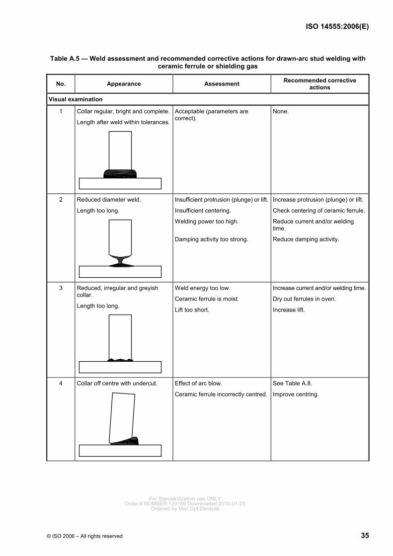
ISO 14555:2006(E)
© ISO 2006 – All rights reserved 35
Table A.5 — Weld assessment and recommended corrective actions for drawn-arc stud welding with ceramic ferrule or shielding gas
No. Appearance Assessment Recommended corrective actions
Visual examination
1 Collar regular, bright and complete.
Length after weld within tolerances.
Acceptable (parameters are correct).
None.
2 Reduced diameter weld.
Length too long.
Insufficient protrusion (plunge) or lift.
Insufficient centering.
Welding power too high.
Damping activity too strong.
Increase protrusion (plunge) or lift.
Check centering of ceramic ferrule.
Reduce current and/or welding time.
Reduce damping activity.
3 Reduced, irregular and greyish collar.
Length too long.
Weld energy too low.
Ceramic ferrule is moist.
Lift too short.
Increase current and/or welding time.
Dry out ferrules in oven.
Increase lift.
4 Collar off centre with undercut.
Effect of arc blow.
Ceramic ferrule incorrectly centred.
See Table A.8.
Improve centring.
For Standardization use ONLYOrder # NUMBER:129169 Downloaded:2010-01-25
Ordered by Mec.Dpt.Derayati
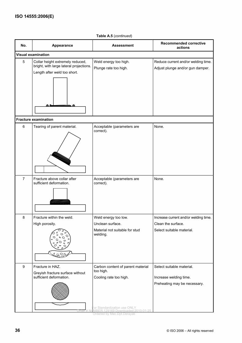
ISO 14555:2006(E)
36 © ISO 2006 – All rights reserved
Table A.5 (continued)
No. Appearance Assessment Recommended corrective actions
Visual examination
5 Collar height extremely reduced, bright, with large lateral projections.
Length after weld too short.
Weld energy too high.
Plunge rate too high.
Reduce current and/or welding time.
Adjust plunge and/or gun damper.
Fracture examination
6 Tearing of parent material.
Acceptable (parameters are correct).
None.
7 Fracture above collar after sufficient deformation.
Acceptable (parameters are correct).
None.
8 Fracture within the weld.
High porosity.
Weld energy too low.
Unclean surface.
Material not suitable for stud welding.
Increase current and/or welding time.
Clean the surface.
Select suitable material.
9 Fracture in HAZ.
Greyish fracture surface without sufficient deformation.
Carbon content of parent material too high.
Cooling rate too high.
Select suitable material.
Increase welding time.
Preheating may be necessary.
For Standardization use ONLYOrder # NUMBER:129169 Downloaded:2010-01-25
Ordered by Mec.Dpt.Derayati
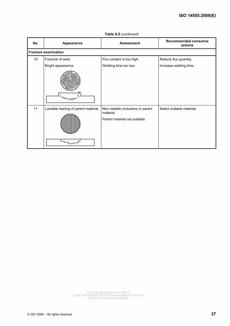
ISO 14555:2006(E)
© ISO 2006 – All rights reserved 37
Table A.5 (continued)
No. Appearance Assessment Recommended corrective actions
Fracture examination
10 Fracture of weld.
Bright appearance.
Flux content is too high.
Welding time too low.
Reduce flux quantity.
Increase welding time.
11 Lamellar tearing of parent material.
Non metallic inclusions in parent material.
Parent material not suitable.
Select suitable material.
For Standardization use ONLYOrder # NUMBER:129169 Downloaded:2010-01-25
Ordered by Mec.Dpt.Derayati
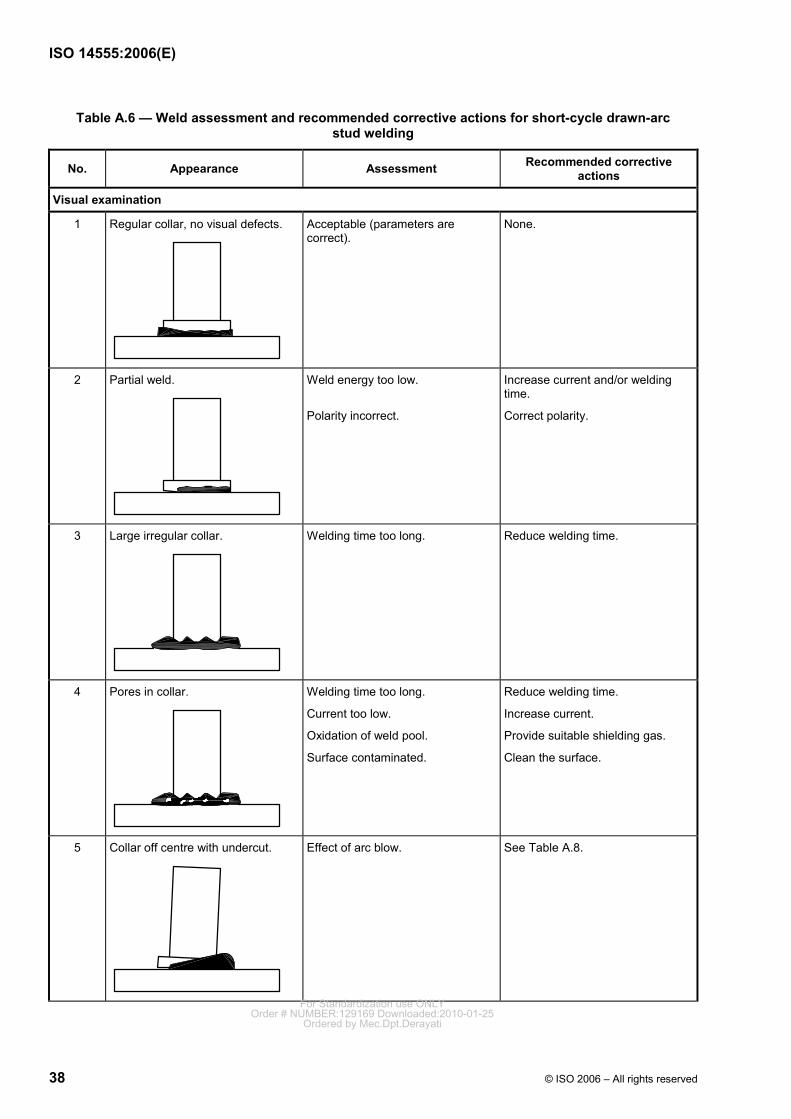
ISO 14555:2006(E)
38 © ISO 2006 – All rights reserved
Table A.6 — Weld assessment and recommended corrective actions for short-cycle drawn-arc stud welding
No. Appearance Assessment Recommended corrective actions
Visual examination
1 Regular collar, no visual defects.
Acceptable (parameters are correct).
None.
2 Partial weld.
Weld energy too low.
Polarity incorrect.
Increase current and/or welding time.
Correct polarity.
3 Large irregular collar.
Welding time too long. Reduce welding time.
4 Pores in collar.
Welding time too long.
Current too low.
Oxidation of weld pool.
Surface contaminated.
Reduce welding time.
Increase current.
Provide suitable shielding gas.
Clean the surface.
5 Collar off centre with undercut.
Effect of arc blow. See Table A.8.
For Standardization use ONLYOrder # NUMBER:129169 Downloaded:2010-01-25
Ordered by Mec.Dpt.Derayati
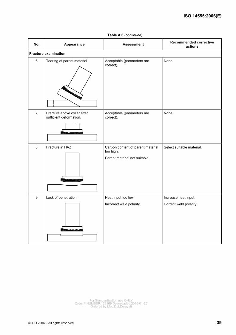
ISO 14555:2006(E)
© ISO 2006 – All rights reserved 39
Table A.6 (continued)
No. Appearance Assessment Recommended corrective actions
Fracture examination
6 Tearing of parent material.
Acceptable (parameters are correct).
None.
7 Fracture above collar after sufficient deformation.
Acceptable (parameters are correct).
None.
8 Fracture in HAZ.
Carbon content of parent material too high.
Parent material not suitable.
Select suitable material.
9 Lack of penetration.
Heat input too low.
Incorrect weld polarity.
Increase heat input.
Correct weld polarity.
For Standardization use ONLYOrder # NUMBER:129169 Downloaded:2010-01-25
Ordered by Mec.Dpt.Derayati
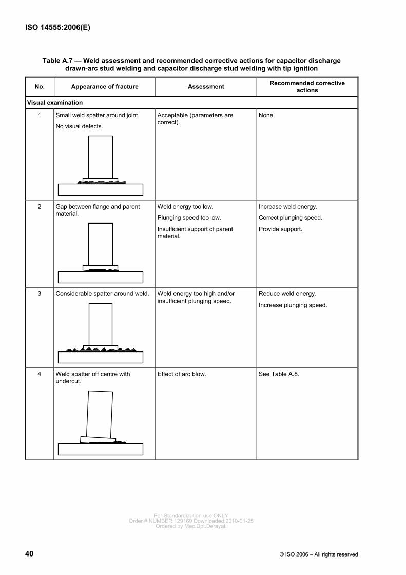
ISO 14555:2006(E)
40 © ISO 2006 – All rights reserved
Table A.7 — Weld assessment and recommended corrective actions for capacitor discharge drawn-arc stud welding and capacitor discharge stud welding with tip ignition
No. Appearance of fracture Assessment Recommended corrective actions
Visual examination
1 Small weld spatter around joint.
No visual defects.
Acceptable (parameters are correct).
None.
2 Gap between flange and parent material.
Weld energy too low.
Plunging speed too low.
Insufficient support of parent material.
Increase weld energy.
Correct plunging speed.
Provide support.
3 Considerable spatter around weld.
Weld energy too high and/or insufficient plunging speed.
Reduce weld energy.
Increase plunging speed.
4 Weld spatter off centre with undercut.
Effect of arc blow. See Table A.8.
For Standardization use ONLYOrder # NUMBER:129169 Downloaded:2010-01-25
Ordered by Mec.Dpt.Derayati
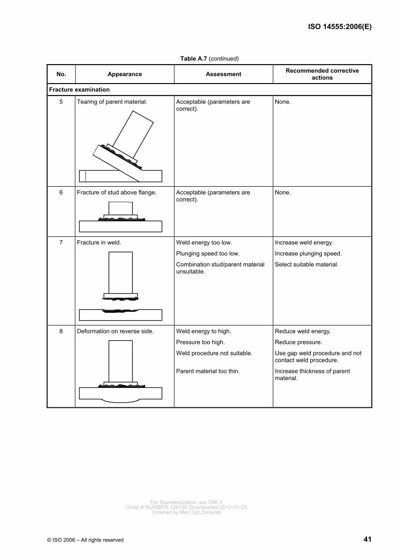
ISO 14555:2006(E)
© ISO 2006 – All rights reserved 41
Table A.7 (continued)
No. Appearance Assessment Recommended corrective actions
Fracture examination
5 Tearing of parent material.
Acceptable (parameters are correct).
None.
6 Fracture of stud above flange.
Acceptable (parameters are correct).
None.
7 Fracture in weld.
Weld energy too low.
Plunging speed too low.
Combination stud/parent material unsuitable.
Increase weld energy.
Increase plunging speed.
Select suitable material.
8 Deformation on reverse side.
Weld energy to high.
Pressure too high.
Weld procedure not suitable.
Parent material too thin.
Reduce weld energy.
Reduce pressure.
Use gap weld procedure and not contact weld procedure.
Increase thickness of parent material.
For Standardization use ONLYOrder # NUMBER:129169 Downloaded:2010-01-25
Ordered by Mec.Dpt.Derayati
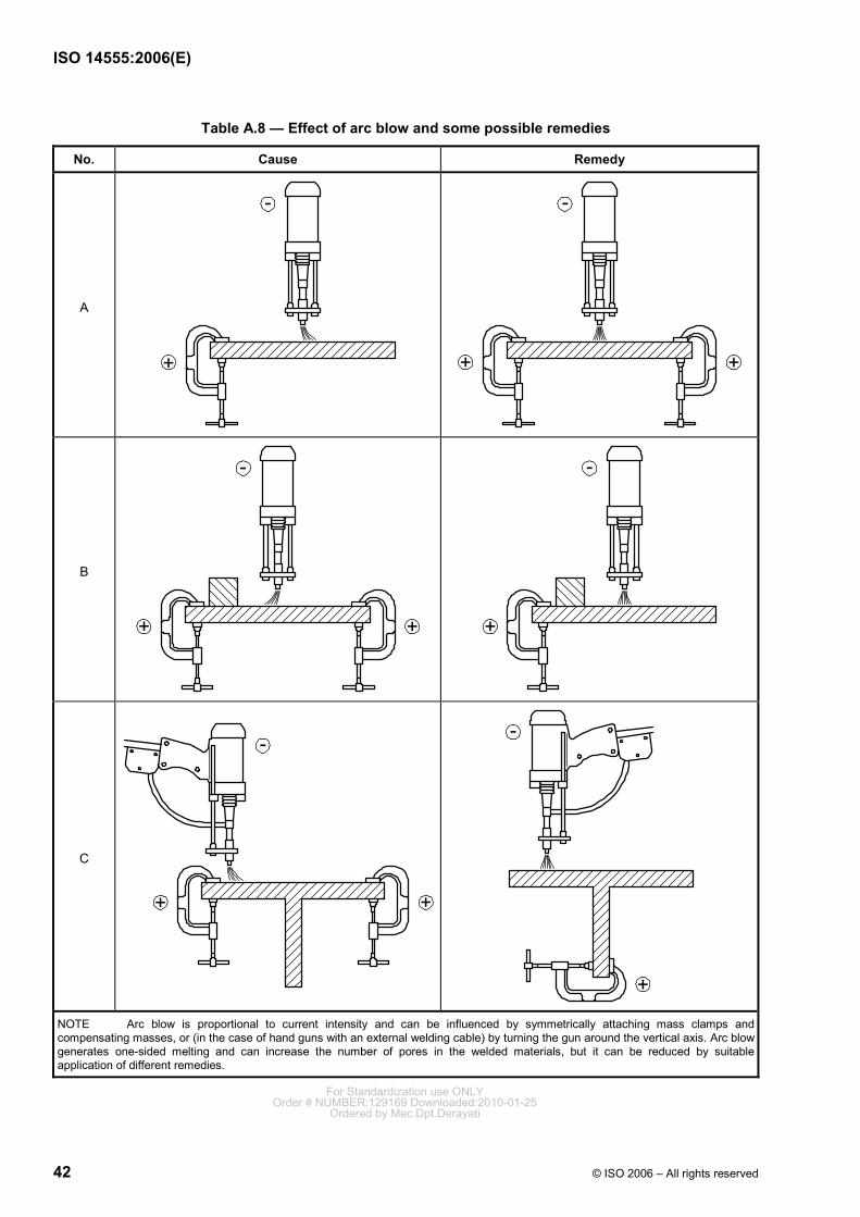
ISO 14555:2006(E)
42 © ISO 2006 – All rights reserved
Table A.8 — Effect of arc blow and some possible remedies
No. Cause Remedy
A
B
C
NOTE Arc blow is proportional to current intensity and can be influenced by symmetrically attaching mass clamps and compensating masses, or (in the case of hand guns with an external welding cable) by turning the gun around the vertical axis. Arc blow generates one-sided melting and can increase the number of pores in the welded materials, but it can be reduced by suitable application of different remedies.
For Standardization use ONLYOrder # NUMBER:129169 Downloaded:2010-01-25
Ordered by Mec.Dpt.Derayati
ISO 14555:2006(E)
© ISO 2006 – All rights reserved 43
A.2.7 Drawn arc stud welding with ceramic ferrule or shielding gas and short-cycle drawn-arc stud welding
A.2.7.1 Welding equipment
A.2.7.1.1 General
The welding equipment consists of the power source, control unit, movable fixture and welding cables.
A.2.7.1.2 Power sources
Power sources are either rectifiers or converters which supply direct current and are suitable for brief, high loads. The maximum current intensity in the case of the largest standard studs is approximately 2 500 A. The duty cycle is 3 % to 10 %. This means that even for high currents, systems are relatively light and compact. The open circuit voltage is between 70 V and 100 V and should conform to IEC 60974-1.
NOTE It is intended that the current intensity be continuously adjustable over the entire range. Systems incorporating constant current control are particularly advantageous.
A.2.7.1.3 Control unit
Control units switch the welding current in accordance with the desired welding time. They also control the movement of the gun. The power source and control unit are combined in most systems (compact systems).
A.2.7.1.4 Movable fixtures
Movable fixtures are either hand-held guns or welding heads. Welding heads are preferable for automatic stud feed and are securely connected to a frame.
The movable fixture incorporates the following:
a) the drive, to lift the stud for arc starting and to keep the lift at a constant length during the arc time, with respect to the support fixture;
NOTE 1 In most cases, the drive is electromagnetic.
b) a spring, to plunge the stud into the molten pool after the end of the welding period;
c) on some guns, a hydraulic or pneumatic damper, to reduce the plunge speed;
NOTE 2 In particular, a damper is incorporated when stud diameters are in excess of 14 mm.
d) a clamping fixture, to hold the stud in the welding position and to transfer the current to the stud;
e) a support fixture, to absorb the reaction force of the press-on force;
NOTE 3 In the case of hand guns, the support fixture can centre the ceramic ferrule or allow the stud to be positioned on the work piece (e.g. by way of stops or templates). The support can be made either directly mechanically, or by means of electronic control.
f) in the case of welding heads for automatic feed, a feed chamber and a positioning unit for the stud.
NOTE 4 In most cases, the positioning unit is pneumatic.
Changing clamping fixtures, and sometimes parts, of the support fixture enables a movable fixture to be used for different stud dimensions.
The movable fixture is a power tool. The appropriate safety regulations should therefore be observed in order to avoid hazards connected with electrical voltage, heating and arc formation.
For Standardization use ONLYOrder # NUMBER:129169 Downloaded:2010-01-25
Ordered by Mec.Dpt.Derayati
ISO 14555:2006(E)
44 © ISO 2006 – All rights reserved
A.2.7.1.5 Welding cables
The welding cables shall conform to ISO 5828 and shall be dimensioned so that impermissible heating is avoided. 50 mm2 is recommended for studs with a diameter of up to 12 mm. Cross-sections of at least 70 mm2 are recommended for studs of up to 20 mm diameter. Cross-sections of 120 mm2 are recommended for larger studs. The cable and, in particular, all connection points should be checked regularly for damage. Damaged system components shall be replaced.
NOTE Depending on the type of power source and the length of the welding cable, the cross-section of the welding cables is increased.
A.2.7.2 Welding parameters
A.2.7.2.1 Polarity
When welding steel, the stud is connected to the negative pole and the work piece is connected to the positive pole. Opposite polarity has proven successful for special metals, e.g. aluminium and its alloys, and brass.
A.2.7.2.2 Welding current
Depending on the stud dimensions, the welding current is between approximately 300 A and 3000 A. For drawn-arc stud welding with ceramic ferrule or shielding gas of unalloyed steel, the correct current can be estimated on the basis of Equations (A.1) and (A.2):
I (A) = 80 × d (mm) — for studs up to approximately 16 mm diameter (A.1)
I (A) = 90 × d (mm) — for studs of over 16 mm diameter (A.2)
Normally, a current approximately 10 % less is selected for stainless steel.
A current as high as possible (600 A to 1 800 A, depending on the size of the power source) is set for short-cycle drawn-arc stud welding.
A.2.7.2.3 Arc voltage
The arc voltage is mainly determined by the lifting height and the welding current. Values of between 20 V and 40 V are the norm. Surface impurities, such as oil or grease, increase the arc voltage compared with the normal state, whilst inert gases reduce it.
A.2.7.2.4 Welding time
For drawn-arc stud welding with ceramic ferrule or shielding gas, the welding time can be estimated on the basis of Equations (A.3) and (A.4):
tw (s) = 0,02 × d (mm) — for studs of up to approximately 12 mm diameter (A.3)
tw (s) = 0,04 × d (mm) — for studs over 12 mm diameter (A.4)
The given values apply to weldings in the welding position PA. The welding time shall be reduced for welding in the welding position PC, in accordance with ISO 6947.
In the case of short cycle stud welding, the welding time is less than 100 ms. It depends not only on the stud diameter, but also on the available current intensity. The welding time should be as short as possible in the case of welding without weld pool protection.
For Standardization use ONLYOrder # NUMBER:129169 Downloaded:2010-01-25
Ordered by Mec.Dpt.Derayati
ISO 14555:2006(E)
© ISO 2006 – All rights reserved 45
A.2.7.2.5 Lift
The lift is between approximately 1,5 mm and 8 mm and is proportional to the stud diameter. In the case of coated surfaces (e.g. through-deck-welding technique), the lift shall be greater than normal. Greater lift increases the arc length and therefore the arc voltage. The magnetic deflection of the arc also increases (arc blow).
A.2.7.2.6 Protrusion
Generally, the protrusion is 1 mm to 8 mm and proportional to the stud diameter. It also depends on the desired shape of the weld collar, the shape of the stud base and (when welding with a ceramic ferrule) the collar area of the ferrule.
A.2.7.2.7 Plunging speed
The plunging speed should be approximately 200 mm/s for studs with a diameter of up to 14 mm diameter and 100 mm/s for larger studs, so as to prevent the weld pool splashing. It is proportional to the protrusion in the case of movable fixtures without dampers.
A.2.8 Capacitor discharge drawn-arc stud welding and capacitor discharge stud welding with tip ignition
A.2.8.1 Welding equipment
A.2.8.1.1 General
The welding equipment consists of the power source, incorporating a charging unit, the movable fixture and the welding cable.
A.2.8.1.2 Power source
The power source incorporates a capacitor bank with capacitances of between approximately 12 mF and 150 mF. The capacitance is sometimes adjustable in steps. The charging voltages are up to approximately 200 V and require a safety switch-off facility conforming to IEC 60974-1. In most cases, the charging voltages are continuously adjustable.
Drawn arc capacitor discharge power sources have an additional coil in the welding circuit to provide a welding time of 6 ms to 10 ms.
The capacitor bank shall be charged to the desired voltage before every welding operation. The maximum welding sequence depends on the charging speed. Approximately 500 studs per hour can be welded with manual-operated power sources, and up to 3 500 studs per hour can be welded in automatic mode.
A.2.8.1.3 Movable fixture
The movable fixtures are either hand guns or welding heads. Welding heads are preferable for automatic stud feed and are securely connected to a frame. In the drawn-arc method, the arc is created by lifting the stud. In the tip ignition method, the electromagnetic drive creates a gap between stud material and parent material. The arc is ignited by contact of the tip to the work piece. The design of the movable fixture depends on whether the method used for starting the arc is the drawn-arc or capacitor discharge method. The movable fixture incorporates the following:
a) the drive, to lift the stud and to keep the lift at a constant length during the arc time, with respect to the support fixture;
NOTE 1 In most cases, the drive is electromagnetic. For Standardization use ONLYOrder # NUMBER:129169 Downloaded:2010-01-25
Ordered by Mec.Dpt.Derayati
ISO 14555:2006(E)
46 © ISO 2006 – All rights reserved
b) a spring, to plunge the stud into the molten pool after the end of the welding period;
c) a clamping fixture, to hold the stud in the welding position and to transfer the current to the stud;
d) a support fixture, to absorb the reaction force of the press-on force;
NOTE 2 In the case of hand guns, the support fixture allows the stud to be positioned on the work piece, (e.g. by way of stops or templates). The support can be made either directly mechanically, or by means of electronic control.
e) in the case of welding heads for automatic feed, a feed chamber and a positioning unit for the stud.
NOTE 3 In most cases, the positioning unit is pneumatic.
An electromagnetic drive is not absolutely essential in the case of movable fixtures operating with stud welding with tip ignition. Springs tensioned by hand can also be used to create the necessary arc gap.
Changing clamping fixtures enables a movable fixture to be used for different stud dimensions.
The movable fixture is a power tool. The appropriate safety regulations should therefore be observed in order to avoid hazards connected with electrical voltage, heating and arc formation.
A.2.8.1.4 Welding cables
Welding cables should be used in accordance with ISO 5828.
The cross-sections of the welding cables are generally 25 mm2 to 70 mm2. They should be as short as possible, due to the high peak currents and the associated voltage drop. Winding the welding cable into coils increases the inductive resistance, which in turn reduces the welding current, but the welding time is increased.
A.2.8.2 Welding parameters
A.2.8.2.1 Polarity
In general, the stud is connected to the negative pole and the work piece is connected to the positive pole. Reverse polarity can be advantageous for copper and aluminium alloys.
A.2.8.2.2 Welding current
The peak current is between 1 000 A and 10 000 A and depends on the charging voltage, the capacitance and the inductive and ohmic resistance of the welding cable.
A.2.8.2.3 Welding time
The welding time cannot be selected directly. Depending on the stored energy and the inductance of the welding circuit, it is 1 ms to 3 ms (tip ignition), or 3 ms to 10 ms (drawn-arc). A longer welding time simplifies welding on a coated surface, by virtue of better degassing.
A.2.8.2.4 Charging energy
Together with the capacitance, the charging voltage determines the charging energy on the basis of Equation (A.5):
20,5W C U= × × (A.5)
The charging energy shall be increased with the weld cross-section. For Standardization use ONLYOrder # NUMBER:129169 Downloaded:2010-01-25
Ordered by Mec.Dpt.Derayati
ISO 14555:2006(E)
© ISO 2006 – All rights reserved 47
A.2.8.2.5 Plunging speed
The plunging speed is in general determined by a spring and the mass of the moving parts. With some movable fixtures, the spring force can be changed by the operator. The plunging speed is approximately 0,5 m/s to 1,5 m/s (sometimes more). In the case of the tip ignition method, it directly determines the welding time, in conjunction with the stud tip length. It is therefore necessary to maintain the plunging speed within limits at all times, in order to obtain a constant quality.
For Standardization use ONLYOrder # NUMBER:129169 Downloaded:2010-01-25
Ordered by Mec.Dpt.Derayati
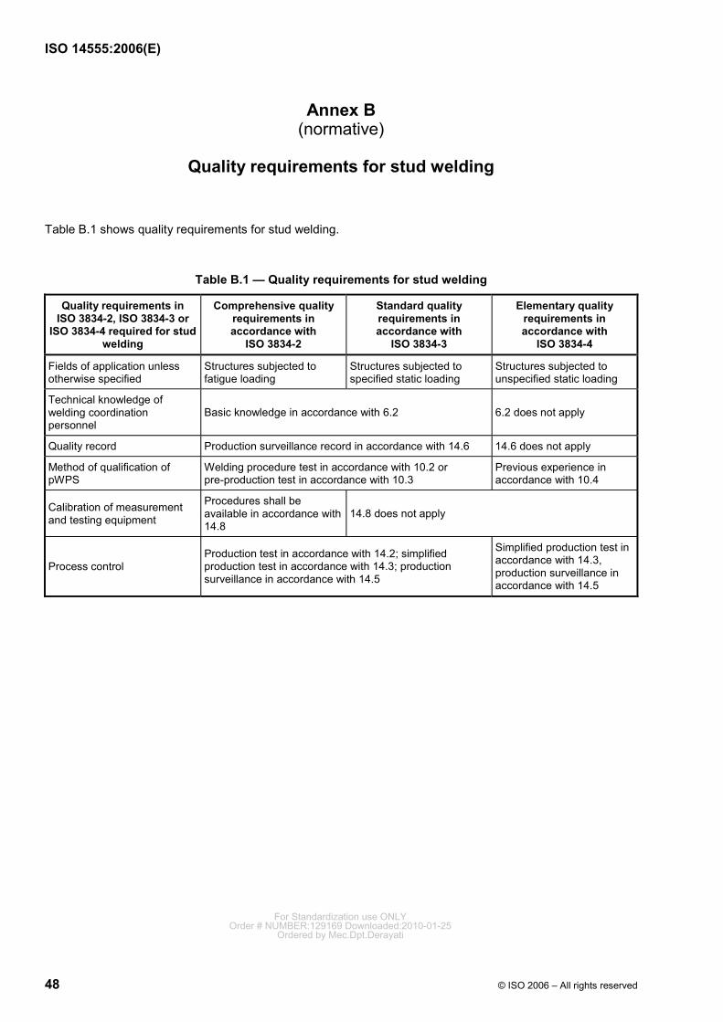
ISO 14555:2006(E)
48 © ISO 2006 – All rights reserved
Annex B (normative)
Quality requirements for stud welding
Table B.1 shows quality requirements for stud welding.
Table B.1 — Quality requirements for stud welding
Quality requirements in ISO 3834-2, ISO 3834-3 or
ISO 3834-4 required for stud welding
Comprehensive quality requirements in accordance with
ISO 3834-2
Standard quality requirements in accordance with
ISO 3834-3
Elementary quality requirements in accordance with
ISO 3834-4
Fields of application unless otherwise specified
Structures subjected to fatigue loading
Structures subjected to specified static loading
Structures subjected to unspecified static loading
Technical knowledge of welding coordination personnel
Basic knowledge in accordance with 6.2 6.2 does not apply
Quality record Production surveillance record in accordance with 14.6 14.6 does not apply
Method of qualification of pWPS
Welding procedure test in accordance with 10.2 or pre-production test in accordance with 10.3
Previous experience in accordance with 10.4
Calibration of measurement and testing equipment
Procedures shall be available in accordance with 14.8
14.8 does not apply
Process control Production test in accordance with 14.2; simplified production test in accordance with 14.3; production surveillance in accordance with 14.5
Simplified production test in accordance with 14.3, production surveillance in accordance with 14.5
For Standardization use ONLYOrder # NUMBER:129169 Downloaded:2010-01-25
Ordered by Mec.Dpt.Derayati
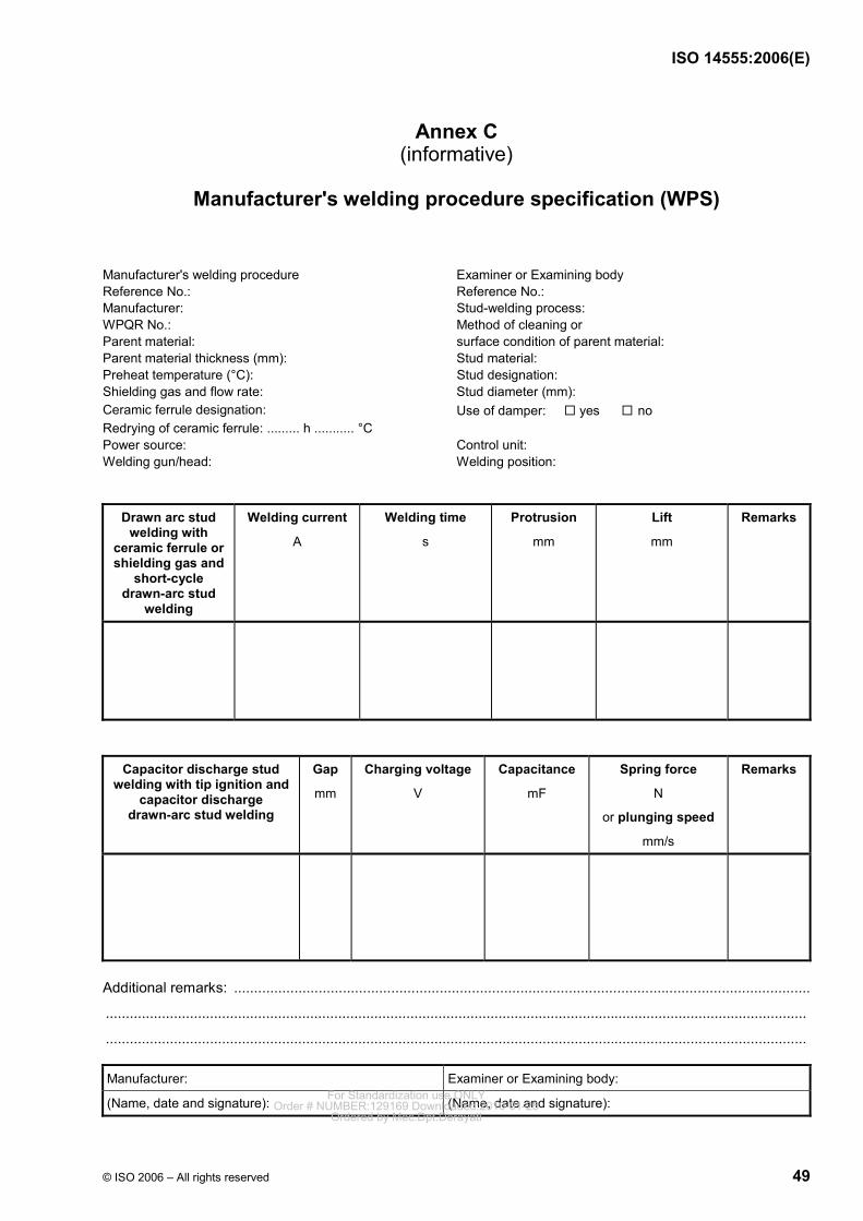
ISO 14555:2006(E)
© ISO 2006 – All rights reserved 49
Annex C (informative)
Manufacturer's welding procedure specification (WPS)
Manufacturer's welding procedure Examiner or Examining body Reference No.: Reference No.: Manufacturer: Stud-welding process: WPQR No.: Method of cleaning or Parent material: surface condition of parent material: Parent material thickness (mm): Stud material: Preheat temperature (°C): Stud designation: Shielding gas and flow rate: Stud diameter (mm): Ceramic ferrule designation: Use of damper: yes no Redrying of ceramic ferrule: ......... h ........... °C Power source: Control unit: Welding gun/head: Welding position:
Drawn arc stud welding with
ceramic ferrule or shielding gas and
short-cycle drawn-arc stud
welding
Welding current
A
Welding time
s
Protrusion
mm
Lift
mm
Remarks
Capacitor discharge stud welding with tip ignition and
capacitor discharge drawn-arc stud welding
Gap
mm
Charging voltage
V
Capacitance
mF
Spring force
N
or plunging speed
mm/s
Remarks
Additional remarks: ...............................................................................................................................................
...............................................................................................................................................................................
...............................................................................................................................................................................
Manufacturer: Examiner or Examining body:
(Name, date and signature): (Name, date and signature): For Standardization use ONLYOrder # NUMBER:129169 Downloaded:2010-01-25
Ordered by Mec.Dpt.Derayati
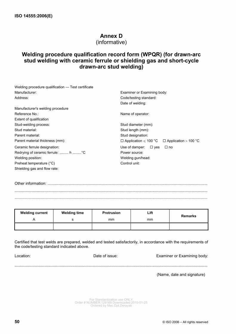
ISO 14555:2006(E)
50 © ISO 2006 – All rights reserved
Annex D (informative)
Welding procedure qualification record form (WPQR) (for drawn-arc stud welding with ceramic ferrule or shielding gas and short-cycle
drawn-arc stud welding)
Welding procedure qualification — Test certificate Manufacturer: Examiner or Examining body: Address: Code/testing standard: Date of welding: Manufacturer's welding procedure Reference No.: Name of operator: Extent of qualification Stud-welding process: Stud diameter (mm): Stud material: Stud length (mm): Parent material: Stud designation: Parent material thickness (mm): Application u 100 °C Application > 100 °C
Ceramic ferrule designation: Use of damper: yes no Redrying of ceramic ferrule: ......... h .........°C Power source: Welding position: Welding gun/head: Preheat temperature (°C) Control unit: Shielding gas and flow rate:
Other information: ..................................................................................................................................................
................................................................................................................................................................................
................................................................................................................................................................................
Welding current
A
Welding time
s
Protrusion
mm
Lift
mm Remarks
Certified that test welds are prepared, welded and tested satisfactorily, in accordance with the requirements of the code/testing standard indicated above.
Location: Date of issue: Examiner or Examining body:
................................................................................................................................................................................
(Name, date and signature)
For Standardization use ONLYOrder # NUMBER:129169 Downloaded:2010-01-25
Ordered by Mec.Dpt.Derayati
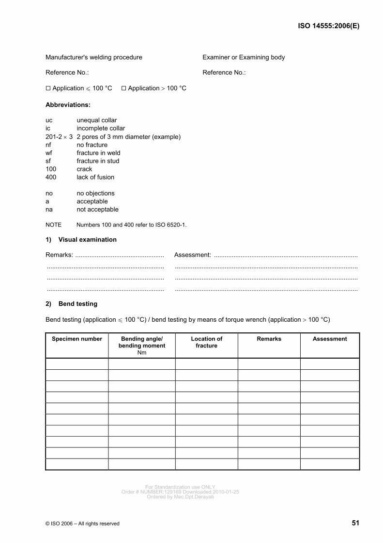
ISO 14555:2006(E)
© ISO 2006 – All rights reserved 51
Manufacturer's welding procedure Examiner or Examining body
Reference No.: Reference No.:
Application u 100 °C Application > 100 °C
Abbreviations:
uc unequal collar ic incomplete collar 201-2 × 3 2 pores of 3 mm diameter (example) nf no fracture wf fracture in weld sf fracture in stud 100 crack 400 lack of fusion no no objections a acceptable na not acceptable
NOTE Numbers 100 and 400 refer to ISO 6520-1.
1) Visual examination
Remarks: .................................................. Assessment: .................................................................................
.................................................................. .......................................................................................................
.................................................................. .......................................................................................................
.................................................................. .......................................................................................................
2) Bend testing
Bend testing (application u 100 °C) / bend testing by means of torque wrench (application > 100 °C)
Specimen number Bending angle/ bending moment
Nm
Location of fracture
Remarks Assessment
For Standardization use ONLYOrder # NUMBER:129169 Downloaded:2010-01-25
Ordered by Mec.Dpt.Derayati
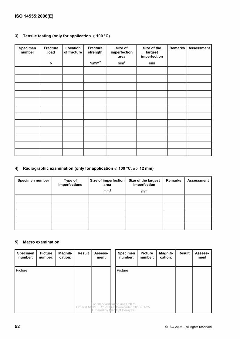
ISO 14555:2006(E)
52 © ISO 2006 – All rights reserved
3) Tensile testing (only for application u 100 °C)
Specimen number
Fracture load
N
Location of fracture
Fracture strength
N/mm2
Size of imperfection
area
mm2
Size of the largest
imperfection
mm
Remarks Assessment
4) Radiographic examination (only for application u 100 °C, d > 12 mm)
Specimen number Type of imperfections
Size of imperfection area
mm2
Size of the largest imperfection
mm
Remarks Assessment
5) Macro examination
Specimen number:
Picture number:
Magnifi-cation:
Result Assess-ment
Specimen number:
Picture number:
Magnifi-cation:
Result Assess-ment
Picture
Picture
For Standardization use ONLYOrder # NUMBER:129169 Downloaded:2010-01-25
Ordered by Mec.Dpt.Derayati
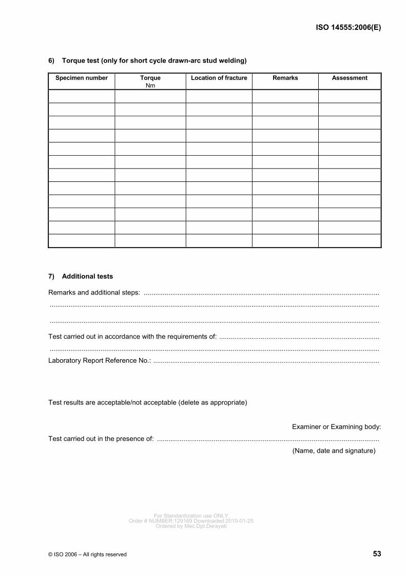
ISO 14555:2006(E)
© ISO 2006 – All rights reserved 53
6) Torque test (only for short cycle drawn-arc stud welding)
Specimen number Torque Nm
Location of fracture Remarks Assessment
7) Additional tests
Remarks and additional steps: .............................................................................................................................
...............................................................................................................................................................................
...............................................................................................................................................................................
Test carried out in accordance with the requirements of: .....................................................................................
...............................................................................................................................................................................
Laboratory Report Reference No.: ........................................................................................................................
Test results are acceptable/not acceptable (delete as appropriate)
Examiner or Examining body:
Test carried out in the presence of: ......................................................................................................................
(Name, date and signature)
For Standardization use ONLYOrder # NUMBER:129169 Downloaded:2010-01-25
Ordered by Mec.Dpt.Derayati
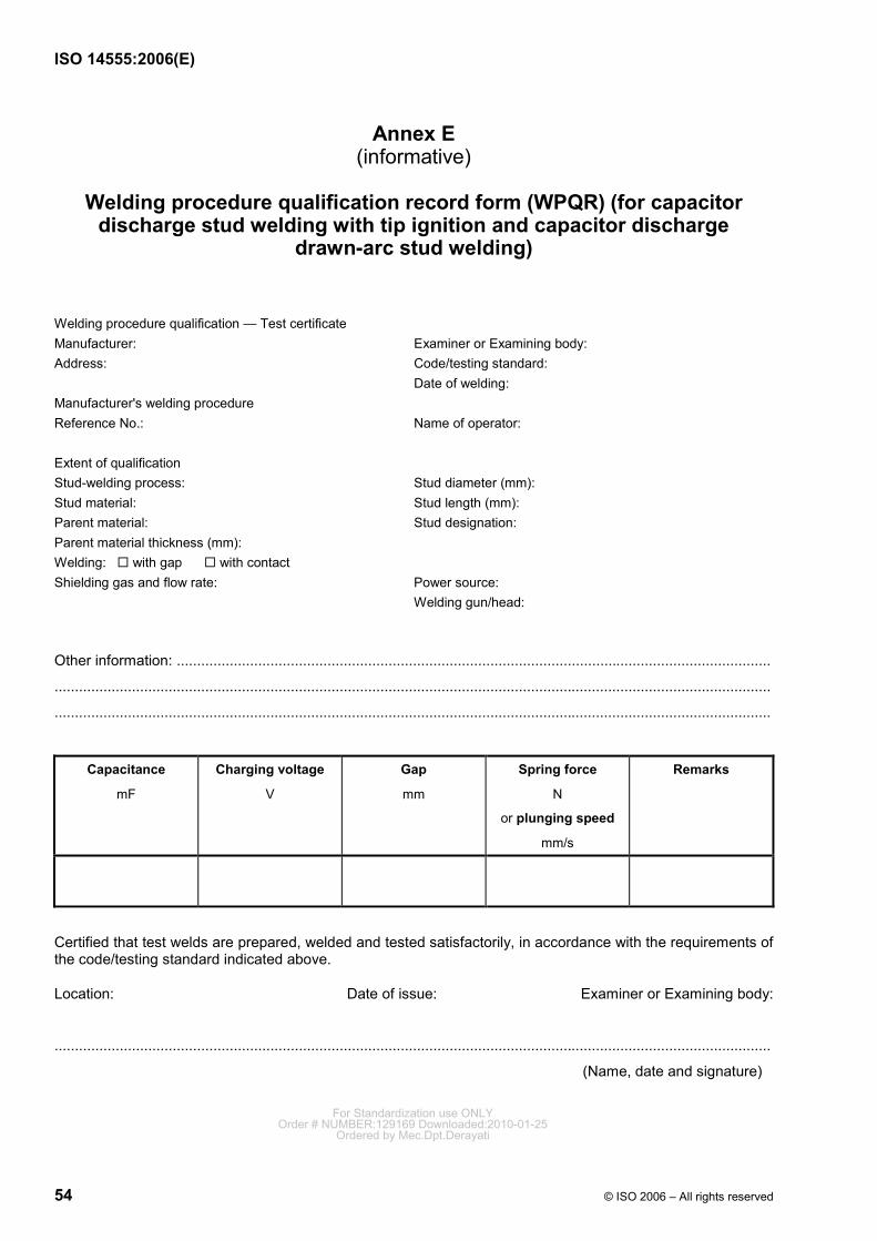
ISO 14555:2006(E)
54 © ISO 2006 – All rights reserved
Annex E (informative)
Welding procedure qualification record form (WPQR) (for capacitor
discharge stud welding with tip ignition and capacitor discharge drawn-arc stud welding)
Welding procedure qualification — Test certificate Manufacturer: Examiner or Examining body: Address: Code/testing standard: Date of welding: Manufacturer's welding procedure Reference No.: Name of operator: Extent of qualification Stud-welding process: Stud diameter (mm): Stud material: Stud length (mm): Parent material: Stud designation: Parent material thickness (mm): Welding: with gap with contact Shielding gas and flow rate: Power source: Welding gun/head:
Other information: ..................................................................................................................................................
................................................................................................................................................................................
................................................................................................................................................................................
Capacitance
mF
Charging voltage
V
Gap
mm
Spring force
N
or plunging speed
mm/s
Remarks
Certified that test welds are prepared, welded and tested satisfactorily, in accordance with the requirements of the code/testing standard indicated above.
Location: Date of issue: Examiner or Examining body:
................................................................................................................................................................................
(Name, date and signature)
For Standardization use ONLYOrder # NUMBER:129169 Downloaded:2010-01-25
Ordered by Mec.Dpt.Derayati
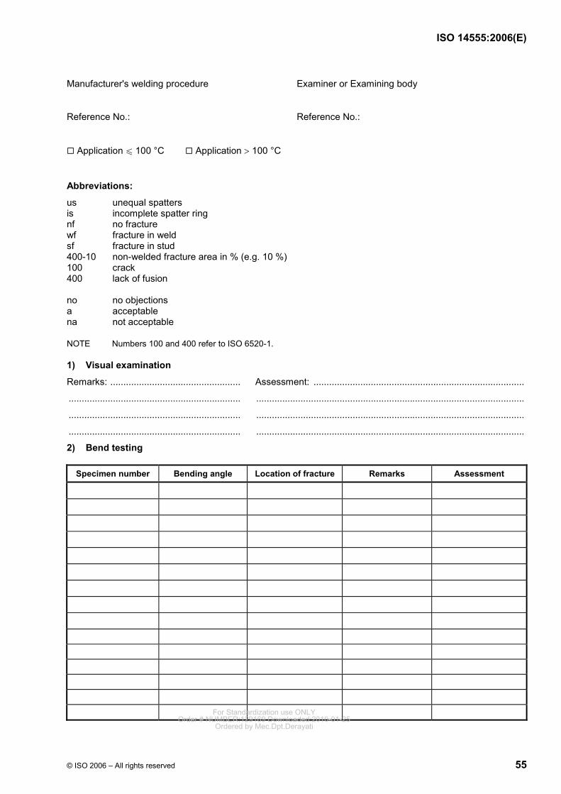
ISO 14555:2006(E)
© ISO 2006 – All rights reserved 55
Manufacturer's welding procedure Examiner or Examining body
Reference No.: Reference No.:
Application u 100 °C Application > 100 °C
Abbreviations:
us unequal spatters is incomplete spatter ring nf no fracture wf fracture in weld sf fracture in stud 400-10 non-welded fracture area in % (e.g. 10 %) 100 crack 400 lack of fusion no no objections a acceptable na not acceptable
NOTE Numbers 100 and 400 refer to ISO 6520-1.
1) Visual examination
Remarks: .................................................. Assessment: .................................................................................
.................................................................. .......................................................................................................
.................................................................. .......................................................................................................
.................................................................. .......................................................................................................
2) Bend testing
Specimen number Bending angle Location of fracture Remarks Assessment
For Standardization use ONLYOrder # NUMBER:129169 Downloaded:2010-01-25
Ordered by Mec.Dpt.Derayati
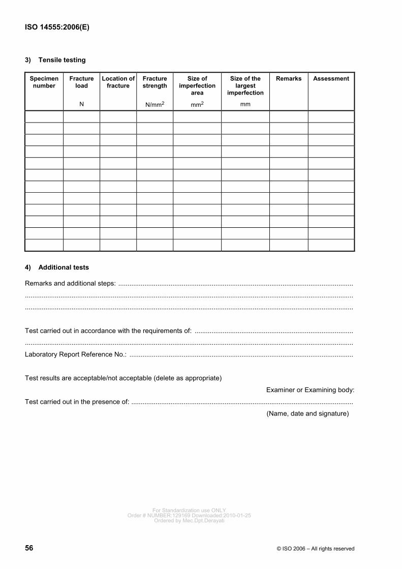
ISO 14555:2006(E)
56 © ISO 2006 – All rights reserved
3) Tensile testing
Specimen number
Fracture load
N
Location of fracture
Fracture strength
N/mm2
Size of imperfection
area
mm2
Size of the largest
imperfection
mm
Remarks Assessment
4) Additional tests
Remarks and additional steps: ..............................................................................................................................
................................................................................................................................................................................
................................................................................................................................................................................
Test carried out in accordance with the requirements of: .....................................................................................
................................................................................................................................................................................
Laboratory Report Reference No.: ........................................................................................................................
Test results are acceptable/not acceptable (delete as appropriate)
Examiner or Examining body:
Test carried out in the presence of: .......................................................................................................................
(Name, date and signature)
For Standardization use ONLYOrder # NUMBER:129169 Downloaded:2010-01-25
Ordered by Mec.Dpt.Derayati
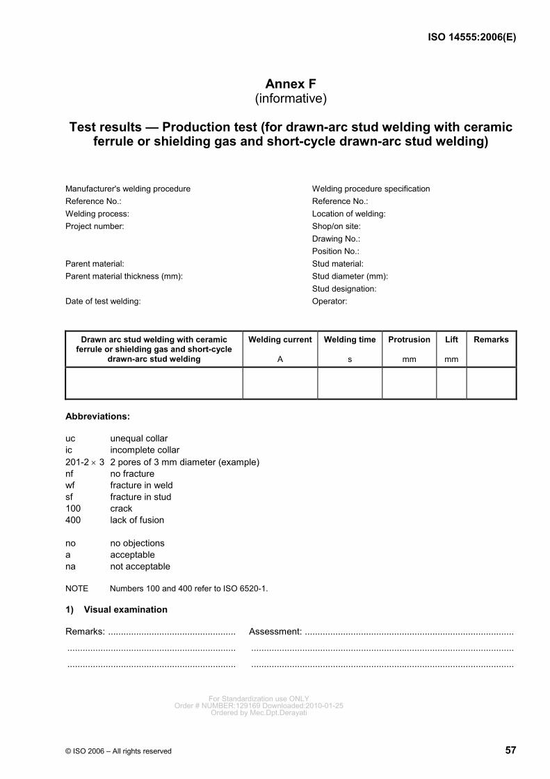
ISO 14555:2006(E)
© ISO 2006 – All rights reserved 57
Annex F (informative)
Test results — Production test (for drawn-arc stud welding with ceramic
ferrule or shielding gas and short-cycle drawn-arc stud welding)
Manufacturer's welding procedure Welding procedure specification Reference No.: Reference No.: Welding process: Location of welding: Project number: Shop/on site: Drawing No.: Position No.: Parent material: Stud material: Parent material thickness (mm): Stud diameter (mm): Stud designation: Date of test welding: Operator:
Drawn arc stud welding with ceramic ferrule or shielding gas and short-cycle
drawn-arc stud welding
Welding current
A
Welding time s
Protrusion
mm
Lift
mm
Remarks
Abbreviations:
uc unequal collar ic incomplete collar 201-2 × 3 2 pores of 3 mm diameter (example) nf no fracture wf fracture in weld sf fracture in stud 100 crack 400 lack of fusion no no objections a acceptable na not acceptable
NOTE Numbers 100 and 400 refer to ISO 6520-1.
1) Visual examination
Remarks: .................................................. Assessment: ..................................................................................
.................................................................. .......................................................................................................
.................................................................. .......................................................................................................
For Standardization use ONLYOrder # NUMBER:129169 Downloaded:2010-01-25
Ordered by Mec.Dpt.Derayati
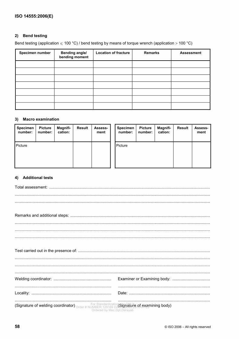
ISO 14555:2006(E)
58 © ISO 2006 – All rights reserved
2) Bend testing
Bend testing (application u 100 °C) / bend testing by means of torque wrench (application > 100 °C)
Specimen number Bending angle/ bending moment
Location of fracture Remarks Assessment
3) Macro examination
Specimen number:
Picture number:
Magnifi-cation:
Result Assess-ment
Specimen number:
Picture number:
Magnifi-cation:
Result Assess-ment
Picture
Picture
4) Additional tests
Total assessment: .................................................................................................................................................
................................................................................................................................................................................
................................................................................................................................................................................
Remarks and additional steps: ..............................................................................................................................
................................................................................................................................................................................
................................................................................................................................................................................
................................................................................................................................................................................
Test carried out in the presence of: .......................................................................................................................
................................................................................................................................................................................
................................................................................................................................................................................
................................................................................................................................................................................
Welding coordinator: .................................................... Examiner or Examining body: ..................................
....................................................................................... ...................................................................................
Locality: ........................................................................ Date: .........................................................................
....................................................................................... ................................................................................... (Signature of welding coordinator) (Signature of examining body) For Standardization use ONLY
Order # NUMBER:129169 Downloaded:2010-01-25Ordered by Mec.Dpt.Derayati
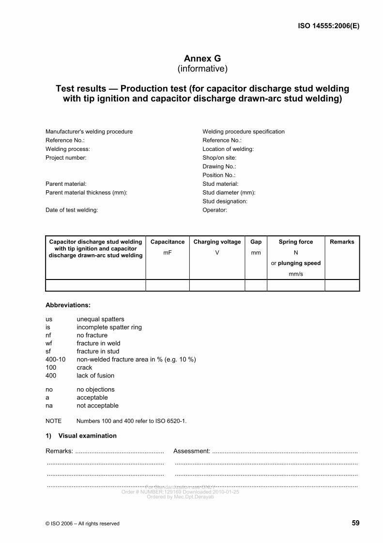
ISO 14555:2006(E)
© ISO 2006 – All rights reserved 59
Annex G (informative)
Test results — Production test (for capacitor discharge stud welding
with tip ignition and capacitor discharge drawn-arc stud welding)
Manufacturer's welding procedure Welding procedure specification Reference No.: Reference No.: Welding process: Location of welding: Project number: Shop/on site: Drawing No.: Position No.: Parent material: Stud material: Parent material thickness (mm): Stud diameter (mm): Stud designation: Date of test welding: Operator:
Capacitor discharge stud welding with tip ignition and capacitor
discharge drawn-arc stud welding
Capacitance
mF
Charging voltage
V
Gap
mm
Spring force
N
or plunging speed
mm/s
Remarks
Abbreviations:
us unequal spatters is incomplete spatter ring nf no fracture wf fracture in weld sf fracture in stud 400-10 non-welded fracture area in % (e.g. 10 %) 100 crack 400 lack of fusion
no no objections a acceptable na not acceptable
NOTE Numbers 100 and 400 refer to ISO 6520-1.
1) Visual examination
Remarks: .................................................. Assessment: ..................................................................................
.................................................................. .......................................................................................................
.................................................................. .......................................................................................................
.................................................................. ....................................................................................................... For Standardization use ONLYOrder # NUMBER:129169 Downloaded:2010-01-25
Ordered by Mec.Dpt.Derayati
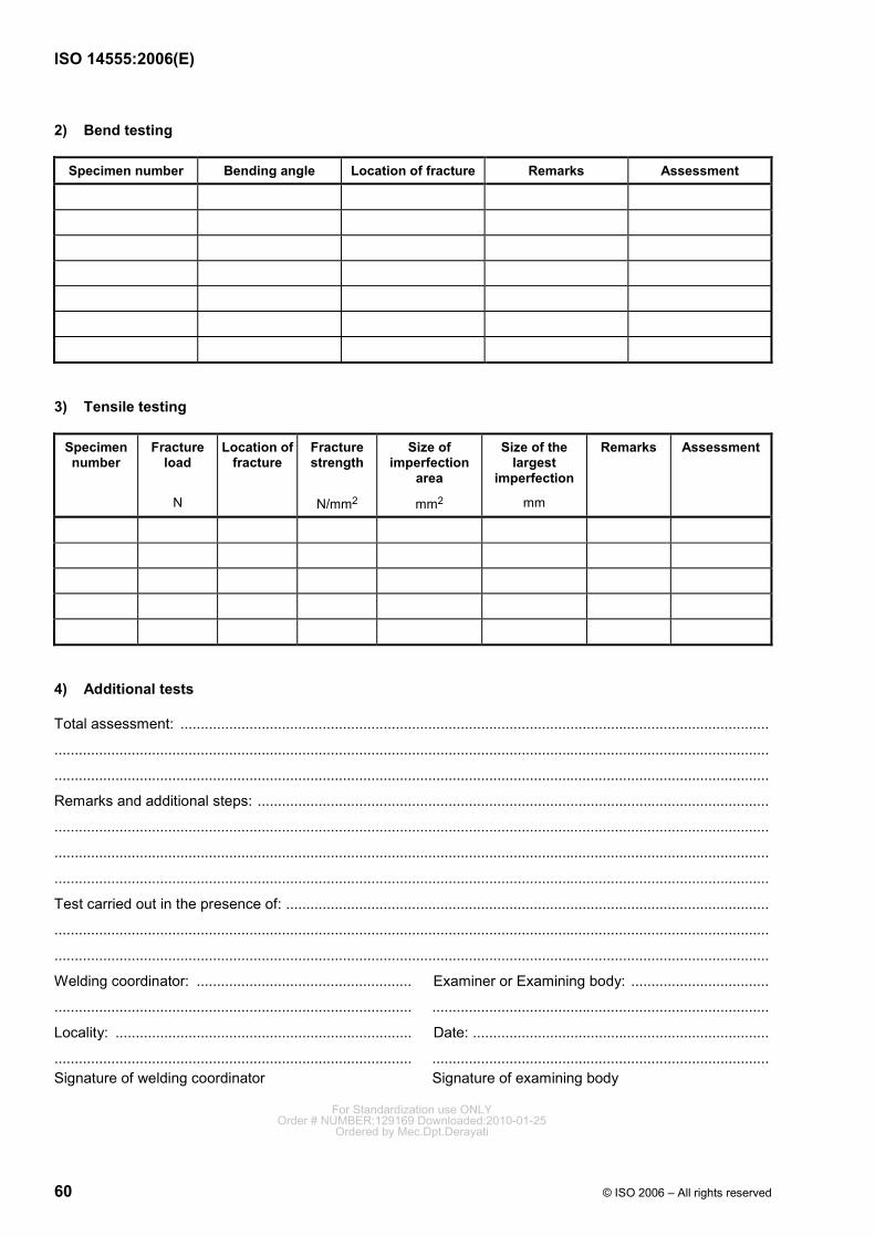
ISO 14555:2006(E)
60 © ISO 2006 – All rights reserved
2) Bend testing
Specimen number Bending angle Location of fracture Remarks Assessment
3) Tensile testing
Specimen number
Fracture load
N
Location of fracture
Fracture strength
N/mm2
Size of imperfection
area
mm2
Size of the largest
imperfection
mm
Remarks Assessment
4) Additional tests
Total assessment: .................................................................................................................................................
................................................................................................................................................................................
................................................................................................................................................................................
Remarks and additional steps: ..............................................................................................................................
................................................................................................................................................................................
................................................................................................................................................................................
................................................................................................................................................................................
Test carried out in the presence of: .......................................................................................................................
................................................................................................................................................................................
................................................................................................................................................................................
Welding coordinator: ..................................................... Examiner or Examining body: ..................................
........................................................................................ ...................................................................................
Locality: ......................................................................... Date: .........................................................................
........................................................................................ ................................................................................... Signature of welding coordinator Signature of examining body
For Standardization use ONLYOrder # NUMBER:129169 Downloaded:2010-01-25
Ordered by Mec.Dpt.Derayati
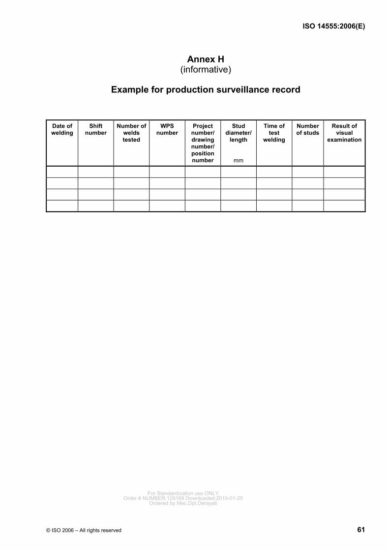
ISO 14555:2006(E)
© ISO 2006 – All rights reserved 61
Annex H (informative)
Example for production surveillance record
Date of welding
Shift number
Number of welds tested
WPS number
Project number/ drawing number/ position number
Stud diameter/
length
mm
Time of test
welding
Number of studs
Result of visual
examination
For Standardization use ONLYOrder # NUMBER:129169 Downloaded:2010-01-25
Ordered by Mec.Dpt.Derayati
ISO 14555:2006(E)
62 © ISO 2006 – All rights reserved
Bibliography
[1] ISO 3834-5, Quality requirements for fusion welding of metallic materials — Part 5: Documents with which it is necessary to conform to claim conformity to the quality requirements of ISO 3834-2, ISO 3834-3 or ISO 3834-4
[2] ISO 5828, Resistance welding equipment — Secondary connecting cables with terminals connected to water-cooled lugs — Dimensions and characteristics
[3] ISO 6520-1, Welding and allied processes — Classification of geometric imperfections in metallic materials — Part 1: Fusion welding
[4] ISO/TR 20172, Welding — Grouping systems for materials — European materials
[5] ISO/TR 20173, Welding — Grouping systems for materials — American materials
[6] ISO/TR 20174, Welding — Grouping systems for materials — Japanese materials
[7] IEC 60974-1, Arc welding equipment — Part 1: Welding power sources
For Standardization use ONLYOrder # NUMBER:129169 Downloaded:2010-01-25
Ordered by Mec.Dpt.Derayati

For Standardization use ONLYOrder # NUMBER:129169 Downloaded:2010-01-25
Ordered by Mec.Dpt.Derayati
ISO 14555:2006(E)
ICS 25.160.10 Price based on 62 pages
© ISO 2006 – All rights reserved
For Standardization use ONLYOrder # NUMBER:129169 Downloaded:2010-01-25
Ordered by Mec.Dpt.Derayati