week 7 compression behaviour of soils · week 7 compression behaviour of soils 10. ... isotropic...
TRANSCRIPT
WEEK 7
Compression Behaviour of Soils
10. Compression behaviour of soils
10-1. Compression in a broader sense
Compression of soil comprises the volume
reduction due to compression of constituent
materials (soil particles, pore water, pore
air, etc.) and consolidation (emigration of
pore water). In this section, we consider
only that due to consolidation. The under-
lying assumption is that the soil in
consideration is well saturated to have
very low undrained compressibility.
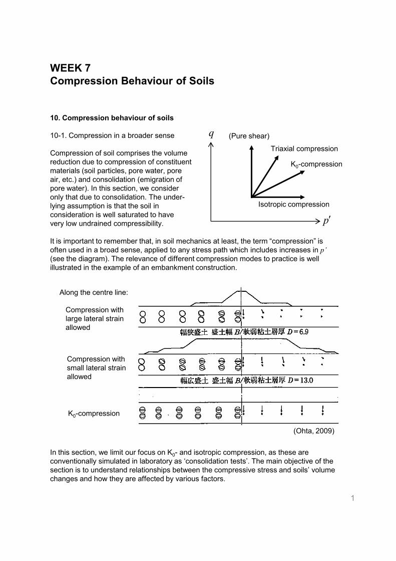
It is important to remember that, in soil mechanics at least, the term “compression” is
often used in a broad sense, applied to any stress path which includes increases in p’
(see the diagram). The relevance of different compression modes to practice is well
illustrated in the example of an embankment construction.
q
p′
(Pure shear)
Isotropic compression
K0-compression
Triaxial compression
In this section, we limit our focus on K0- and isotropic compression, as these are
conventionally simulated in laboratory as ‘consolidation tests’. The main objective of the
section is to understand relationships between the compressive stress and soils’ volume
changes and how they are affected by various factors.
1
K0-compression
(Ohta, 2009)
Compression with
small lateral strain
allowed
Compression with
large lateral strain
allowed
Along the centre line:
10-2. Test apparatus
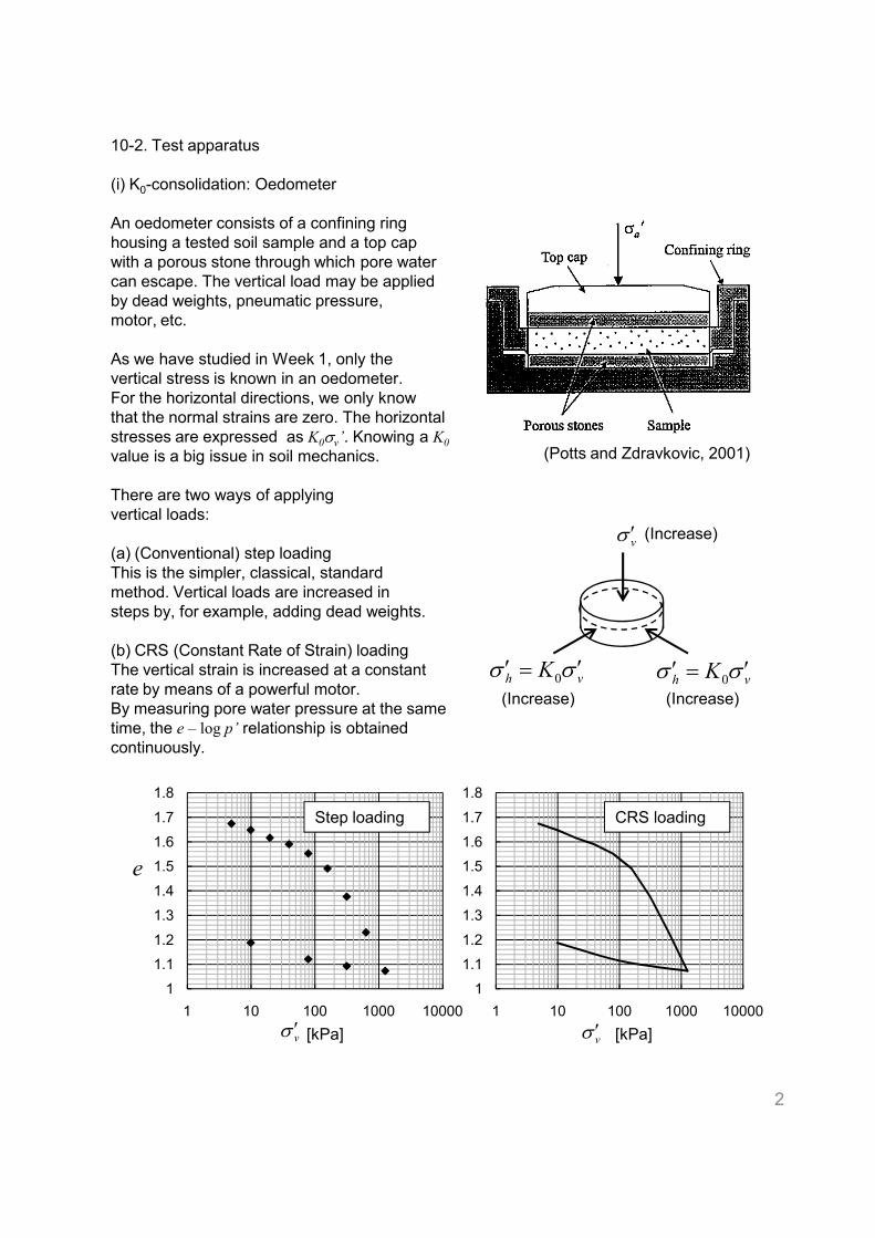
(i) K0-consolidation: Oedometer
An oedometer consists of a confining ring
housing a tested soil sample and a top cap
with a porous stone through which pore water
can escape. The vertical load may be applied
by dead weights, pneumatic pressure,
motor, etc.
As we have studied in Week 1, only the
vertical stress is known in an oedometer.
For the horizontal directions, we only know
that the normal strains are zero. The horizontal
stresses are expressed as K0σv’. Knowing a K0value is a big issue in soil mechanics.
There are two ways of applying
vertical loads:
(a) (Conventional) step loading
This is the simpler, classical, standard
method. Vertical loads are increased in
steps by, for example, adding dead weights.
(Potts and Zdravkovic, 2001)
vσ ′ (Increase)
steps by, for example, adding dead weights.
(b) CRS (Constant Rate of Strain) loading
The vertical strain is increased at a constant
rate by means of a powerful motor.
By measuring pore water pressure at the same
time, the e – log p’ relationship is obtained
continuously.
2
vh K σσ ′=′ 0
(Increase) (Increase)
vh K σσ ′=′ 0
1
1.1
1.2
1.3
1.4
1.5
1.6
1.7
1.8
1 10 100 1000 10000
1
1.1
1.2
1.3
1.4
1.5
1.6
1.7
1.8
1 10 100 1000 10000
e
vσ ′ [kPa] [kPa]
Step loading CRS loading
vσ ′
(ii) Isotropic consolidation
Although isotropic consolidation is notionally
simpler than K0-consolidation, performing tests
no easier. It requires high pressure, and factors
such as membrane penetration need to be
considered.
In this week’s lecture, the compression curves
shown are all obtained for K0-conditions,
unless specified otherwise.
10-3. Sedimentation and normal consolidation of clayey soils
(i) Sedimentation Compression Curve
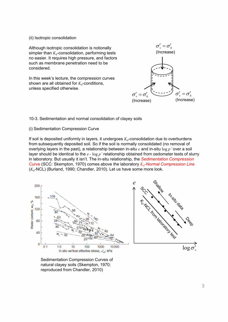
If soil is deposited uniformly in layers, it undergoes K0-consolidation due to overburdens
from subsequently deposited soil. So if the soil is normally consolidated (no removal of
overlying layers in the past), a relationship between in-situ e and in-situ log p’ over a soil
layer should be identical to the e - log p’ relationship obtained from oedometer tests of slurry
in laboratory. But usually it isn’t. The in-situ relationship, the Sedimentation Compression
hv σσ ′=′(Increase)
hv σσ ′=′(Increase)
hv σσ ′=′(Increase)
in laboratory. But usually it isn’t. The in-situ relationship, the Sedimentation Compression
Curve (SCC: Skempton, 1970) comes above the laboratory K0-Normal Compression Line
(K0-NCL) (Burland, 1990; Chandler, 2010). Let us have some more look.
3
e
vσ ′log
Sedimentation Compression Curves of
natural clayey soils (Skempton, 1970;
reproduced from Chandler, 2010)
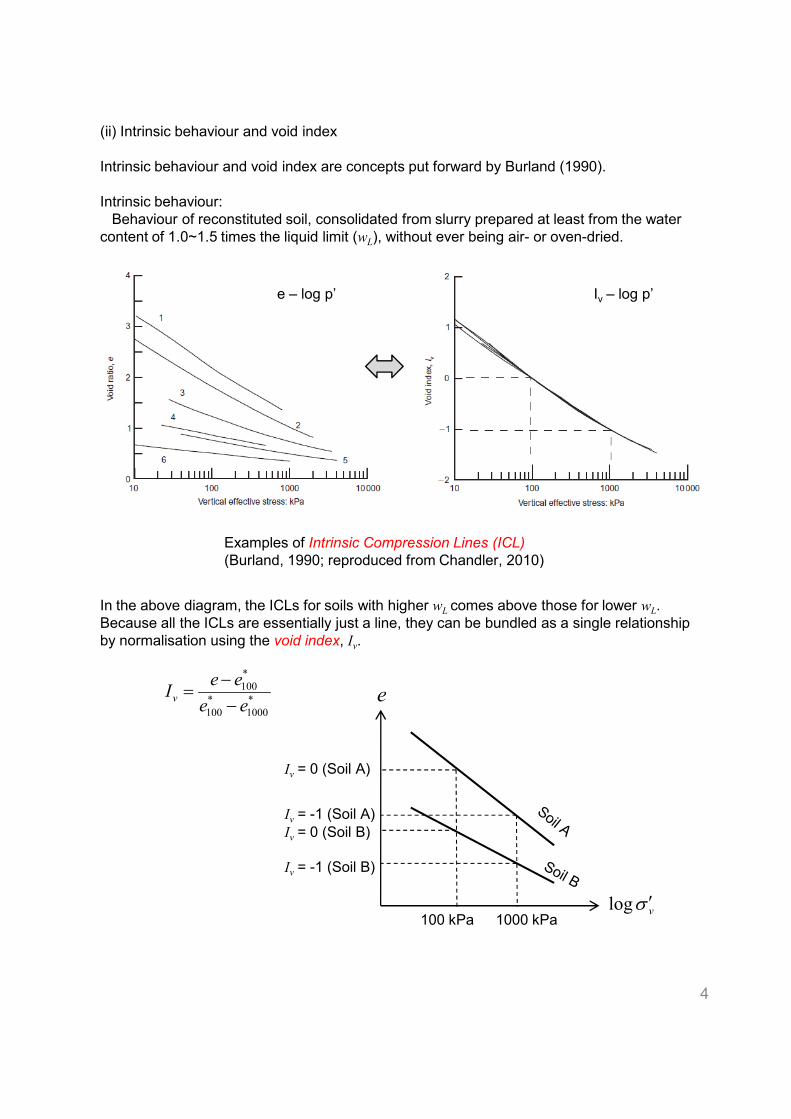
(ii) Intrinsic behaviour and void index
Intrinsic behaviour and void index are concepts put forward by Burland (1990).
Intrinsic behaviour:
Behaviour of reconstituted soil, consolidated from slurry prepared at least from the water
content of 1.0~1.5 times the liquid limit (wL), without ever being air- or oven-dried.
Examples of Intrinsic Compression Lines (ICL)
(Burland, 1990; reproduced from Chandler, 2010)
e – log p’ Iv – log p’
In the above diagram, the ICLs for soils with higher wL comes above those for lower wL.
Because all the ICLs are essentially just a line, they can be bundled as a single relationship
by normalisation using the void index, Iv.
4
(Burland, 1990; reproduced from Chandler, 2010)
*
1000
*
100
*
100
ee
eeIv −
−= e
vσ ′log100 kPa 1000 kPa
Iv = 0 (Soil A)
Iv = 0 (Soil B)
Iv = -1 (Soil A)
Iv = -1 (Soil B)
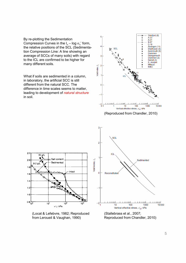
By re-plotting the Sedimentation
Compression Curves in the Iv – log σv’ form,the relative positions of the SCL (Sedimenta-
tion Compression Line: A line showing an
average of SCCs of many soils) with regard
to the ICL are confirmed to be higher for
many different soils.
What if soils are sedimented in a column,
in laboratory, the artificial SCC is still
different from the natural SCC. The
difference in time scales seems to matter,
leading to development of natural structure
in soil.
(Reproduced from Chandler, 2010)
5
(Stallebrass et al., 2007;
Reproduced from Chandler, 2010)
(Locat & Lefebvre, 1982; Reproduced
from Leroueil & Vaughan, 1990)
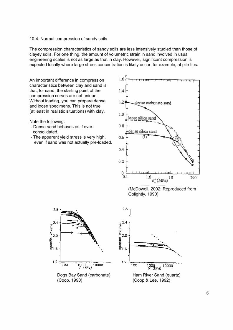
10-4. Normal compression of sandy soils
The compression characteristics of sandy soils are less intensively studied than those of
clayey soils. For one thing, the amount of volumetric strain in sand involved in usual
engineering scales is not as large as that in clay. However, significant compression is
expected locally where large stress concentration is likely occur; for example, at pile tips.
An important difference in compression
characteristics between clay and sand is
that, for sand, the starting point of the
compression curves are not unique.
Without loading, you can prepare dense
and loose specimens. This is not true
(at least in realistic situations) with clay.
Note the following:
- Dense sand behaves as if over-
consolidated.
- The apparent yield stress is very high,
even if sand was not actually pre-loaded.
6
(McDowell, 2002; Reproduced from
Golightly, 1990)
Dogs Bay Sand (carbonate)
(Coop, 1990)
Ham River Sand (quartz)
(Coop & Lee, 1992)
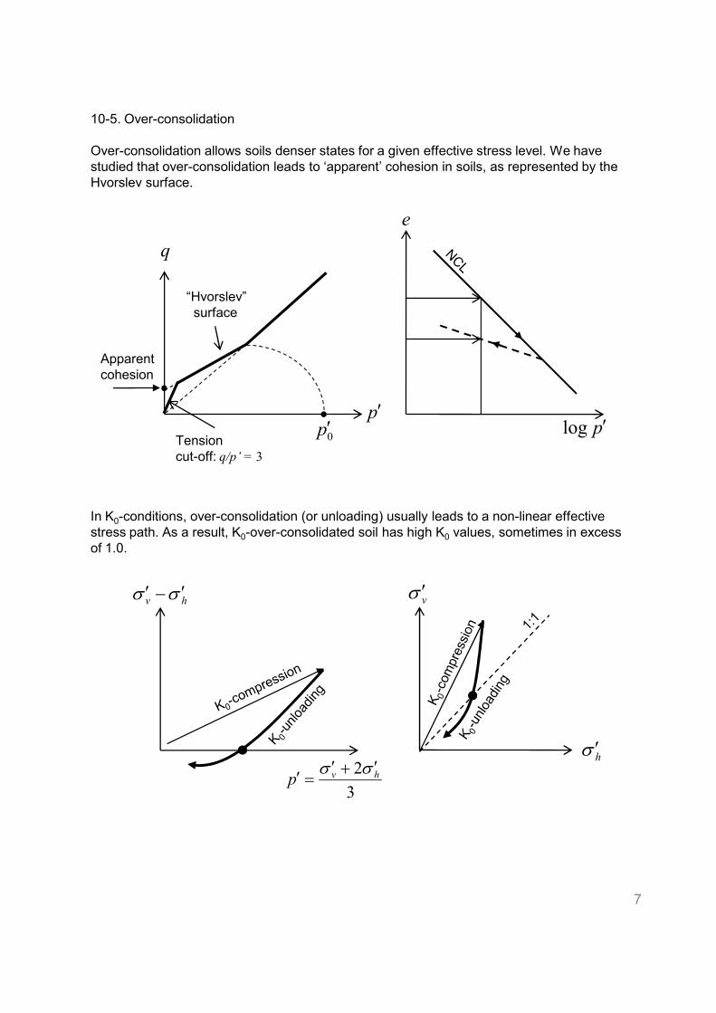
10-5. Over-consolidation
Over-consolidation allows soils denser states for a given effective stress level. We have
studied that over-consolidation leads to ‘apparent’ cohesion in soils, as represented by the
Hvorslev surface.
q
p′0p′
“Hvorslev”
surface
Apparent
cohesion
Tension
cut-off: q/p’ = 3
p′log
e
In K0-conditions, over-consolidation (or unloading) usually leads to a non-linear effective
stress path. As a result, K0-over-consolidated soil has high K0 values, sometimes in excess
of 1.0.
7
hv σσ ′−′
3
2 hvpσσ ′+′
=′hσ ′
vσ ′
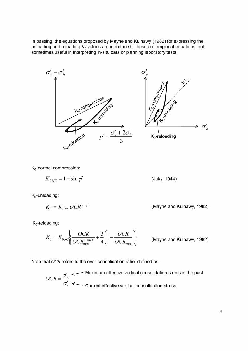
In passing, the equations proposed by Mayne and Kulhawy (1982) for expressing the
unloading and reloading K0 values are introduced. These are empirical equations, but
sometimes useful in interpreting in-situ data or planning laboratory tests.
K0-normal compression:
hv σσ ′−′
3
2 hvpσσ ′+′
=′hσ ′
vσ ′
K0-reloading
φ ′−= sin1K (Jaky, 1944)
K0-unloading:
(Mayne and Kulhawy, 1982)
K0-reloading:
(Mayne and Kulhawy, 1982)
Note that OCR refers to the over-consolidation ratio, defined as
8
φ ′−= sin10NCK
'sin
00
φOCRKK NC=
−+=
−max
'sin1
max
00 14
3
OCR
OCR
OCR
OCRKK NC φ
v
vcOCRσσ′′
=Maximum effective vertical consolidation stress in the past
Current effective vertical consolidation stress
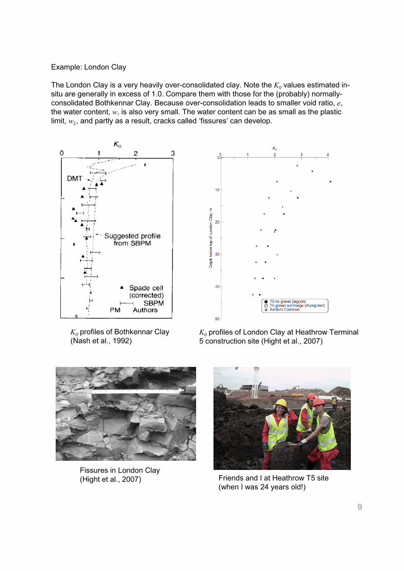
Example: London Clay
The London Clay is a very heavily over-consolidated clay. Note the K0 values estimated in-
situ are generally in excess of 1.0. Compare them with those for the (probably) normally-
consolidated Bothkennar Clay. Because over-consolidation leads to smaller void ratio, e,
the water content, w, is also very small. The water content can be as small as the plastic
limit, wL, and partly as a result, cracks called ‘fissures’ can develop.
9
K0 profiles of London Clay at Heathrow Terminal
5 construction site (Hight et al., 2007)
Fissures in London Clay
(Hight et al., 2007) Friends and I at Heathrow T5 site
(when I was 24 years old!)
K0 profiles of Bothkennar Clay
(Nash et al., 1992)
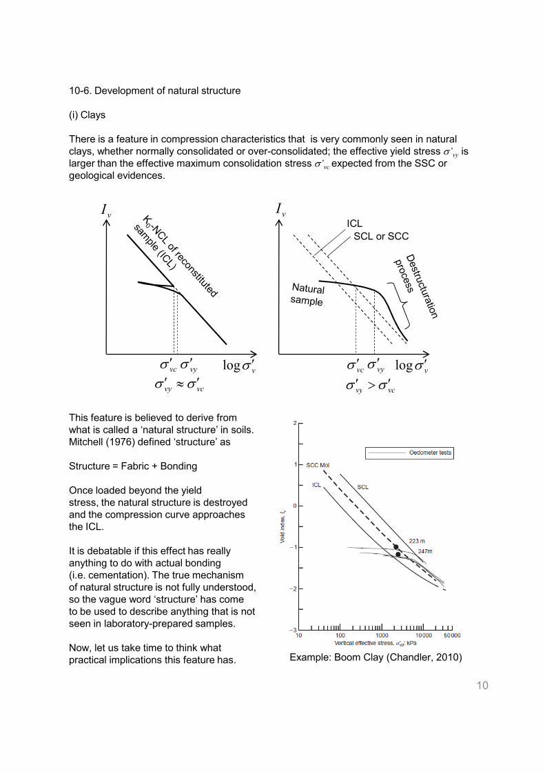
10-6. Development of natural structure
(i) Clays
There is a feature in compression characteristics that is very commonly seen in natural
clays, whether normally consolidated or over-consolidated; the effective yield stress σ’vy is larger than the effective maximum consolidation stress σ’vc expected from the SSC or geological evidences.
vI
vσ ′log vσ ′logvcσ ′ vyσ ′ vyσ ′
ICL
SCL or SCC
vI
vcσ ′
vcvy σσ ′≈′vcvy σσ ′>′
This feature is believed to derive from
what is called a ‘natural structure’ in soils.
Mitchell (1976) defined ‘structure’ as
Structure = Fabric + Bonding
Once loaded beyond the yield
stress, the natural structure is destroyed
and the compression curve approaches
the ICL.
It is debatable if this effect has really
anything to do with actual bonding
(i.e. cementation). The true mechanism
of natural structure is not fully understood,
so the vague word ‘structure’ has come
to be used to describe anything that is not
seen in laboratory-prepared samples.
Now, let us take time to think what
practical implications this feature has.
10
Example: Boom Clay (Chandler, 2010)
vcvy σσ ′≈′vcvy σσ ′>′
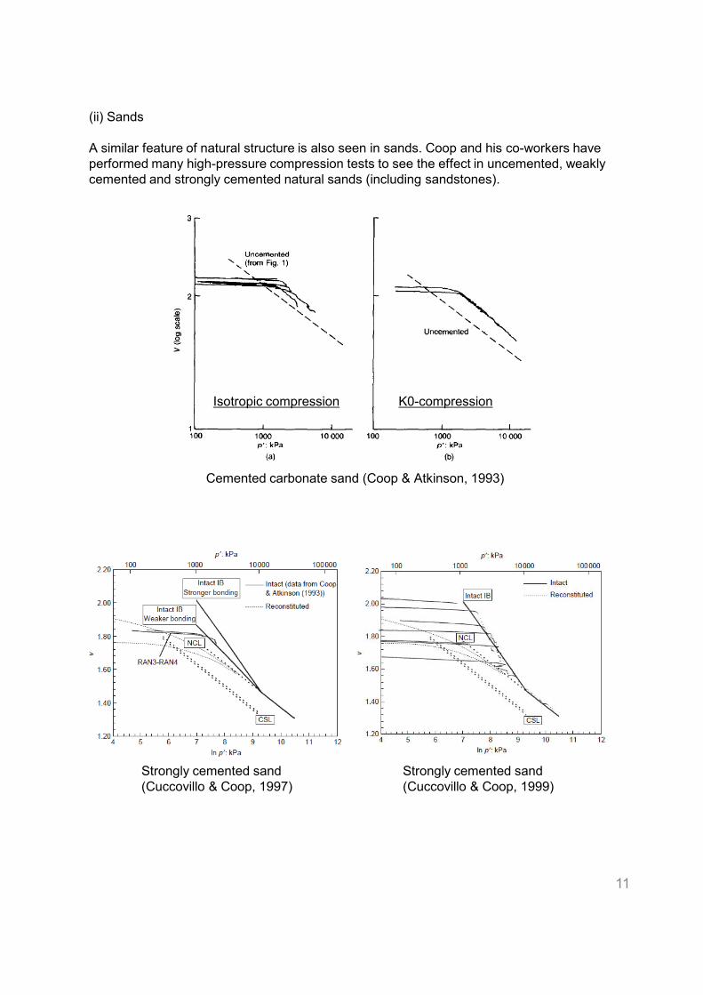
(ii) Sands
A similar feature of natural structure is also seen in sands. Coop and his co-workers have
performed many high-pressure compression tests to see the effect in uncemented, weakly
cemented and strongly cemented natural sands (including sandstones).
Cemented carbonate sand (Coop & Atkinson, 1993)
K0-compressionIsotropic compression
11
Strongly cemented sand
(Cuccovillo & Coop, 1997)
Strongly cemented sand
(Cuccovillo & Coop, 1999)
References
Burland, J. B. (1990) “On the compressibility and shear strength of natural clays,”
Geotechnique 40(3) 329–378.
Chandler, R.J. (2010) “Stiff sedimentary clays: geological origins and engineering
properties,” Geotechnique 60(12) 891-902.
Coop, M.R. (1990) “The mechanics of uncemented carbonate sands,” Geotechnique 40(4)
607-626.
Coop, M. R. & Atkinson, J. H. (1993) “The mechanics of cemented carbonate sands,”
Geotechnique 43(1) 53-67.
Coop, M.R. and Lee, (1993) “The behaviour of granular soils at elevated stresses,”
Proceedings of Wroth Memorial Symposium: Predictive Soil Mechanics, Thomas Telford,
London, 86-198.
Cuccovillo, T. and Coop, M. R. (1997) “Yielding and prefailure behaviour of structured
sands,” Geotechnique 47(3) 491-508.
Cuccovillo, T. and Coop, M.R. (1999) “On the mechanics of structured sands,”
Geotechnique 49(6) 741-760.
Golightly, C.R. (1990) “Engineering properties of carbonate sands,” PhD Dissertation,
Bradford University.
Hight, D. W., Gasparre, A., Nishimura, S., Minh, N. A., Jardine, R. J. and Coop, M. R.
(2007) “Characteristics of the London Clay from the Terminal 5 site at Heathrow Airport,”
Geotechnique 57(1) 3–18.
Jaky, J. (1944) “The coefficient of earth pressure at rest,” J. of the Union of Hungarian
Engineers and Architects, 355-358 (in Hungarian).Engineers and Architects, 355-358 (in Hungarian).
Leroueil, S. and Vaughan, P.R. (1990) “The general and congruent effects of structure in
natural soils and weak rocks,” Geotechnique 40(3) 467-488.
Locat, J. and Lefebvre, G. (1985) “The compressibility and sensitivity of an artificially
sedimented clay soil: the Grande-Baleine marine clay, Quebec,” Marine Geotechnol. 6(1)
1-27.
Mayne, P.W. and Kulhawy, F.H. (1982): “K0-OCR relationships in soil,” Journal of
Geotechnical Engineering Division, ASCE, 108(GT6) 851-872.
McDowell, G. (2001) “On the yielding and plastic compression of sand,” Soils and
Foundations 42(1) 139-145.
Mitchell, J.K. (1976): “Fundamentals of soil behavior,” John Wiley & Sons, Inc.
Nash, D. F. T., Powell, J. J. M. & Lloyd, I. M. (1992) “Initial investigations of the soft clay
test site at Bothkennar,” Geotechnique 42(2) 163-181.
Ohta, H. (2009) “Settlement of embankments”, The Monthly Bulletin of Japanese
Geotechnical Society, 57(3) 46-53.
Potts, D.M. and Zdravkovic, L. (2001) “Finite element analysis in geotechnical engineering:
Application,” Thomas Telford, London.
Skempton, A.W. (1970) “The consolidation of clays by gravitational compaction,” Q. J.
Geol.
Soc. London 125, 373–412.
Stallebrass, S. E., Atkinson, J. H. and Masin, D. (2007) “Manufacture of samples of
overconsolidated clay by laboratory sedimentation,” Geotechnique 57(2) 249–253.
12