web-enabled interface for an adaptive systems’ interactive...
TRANSCRIPT
WEB-ENABLED INTERFACE FOR AN ADAPTIVE SYSTEMS’ INTERACTIVE BOOK
By
RAJESH KUMAR
A THESIS PRESENTED TO THE GRADUATE SCHOOL OF THE UNIVERSITY OF FLORIDA IN PARTIAL FULFILLMENT
OF THE REQUIREMENTS FOR THE DEGREE OF MASTER OF SCIENCE
UNIVERSITY OF FLORIDA
2001

Copyright 2001
by
Rajesh Kumar

To my Teachers

iv
ACKNOWLEDGMENTS
I express my sincere gratitude to my advisor, Dr. Jose C. Principe for giving me
an opportunity to work on this challenging topic and for providing continuous guidance
and feedback during the course of this work and thesis writing.
I thank Dr. Joachim Hammer and Dr. Herman Lam for serving on my supervisory
committee and for their careful review of this thesis.
I am also thankful to Dan Wooten, Dr. Neil Euliano and Gary of NeuroDimension
Inc. for the valuable discussions and help on the number of topics related to this thesis.
I also wish to take this opportunity to thank my parents and my friends at UF and
CNEL for their support and encouragement throughout my academic career.
v
TABLE OF CONTENTS
page
ACKNOWLEDGMENTS .................................................................................................. iv
LIST OF FIGURES ........................................................................................................... vii
ABSTRACT........................................................................................................................ ix
INTRODUCTION ...............................................................................................................1
1.1 Background on Interactive Teaching and Learning.................................................. 1 1.2 Present State of the Electronic Book ........................................................................ 3 1.3 Motivation for the Web Interface in the Electronic Book ........................................ 4 1.4 Requirement Specification........................................................................................ 4 1.5 Approach: Java APIs................................................................................................. 5 1.6 Organization of Thesis .............................................................................................. 6
CLIENT-SERVER ARCHITECTURE ...............................................................................7
2.1 Introduction............................................................................................................... 7 2.2 Architecture Model ................................................................................................... 7 2.3 Common Architectural Models................................................................................. 8 2.4 Communication Model ........................................................................................... 10 2.5 Summary................................................................................................................. 11
FUNDAMENTAL SYSTEM COMPONENTS ................................................................13
3.1 Introduction............................................................................................................. 13 3.2 Java Native Interface............................................................................................... 13 3.3 Applet...................................................................................................................... 16 3.4 Servlet Technologies............................................................................................... 20 3.5 Applet-Servlet Communication .............................................................................. 25 3.6 Web Server.............................................................................................................. 30 3.7 NeuroSolutions™.................................................................................................... 31 3.8 Summary................................................................................................................. 38
vi
SYSTEM DESIGN AND IMPLEMENTATION..............................................................39
4.1 Introduction............................................................................................................. 39 4.2 System Design ........................................................................................................ 39 4.3 System Architecture ................................................................................................ 44 4.4 Logical System Flow .............................................................................................. 46 4.5 Communication Methodologies .............................................................................. 49 4.6 Graphical User Interface ......................................................................................... 52 4.7 Programs Overview................................................................................................. 53 4.8 Implementation Process .......................................................................................... 54 4.9 Summary................................................................................................................. 60
RESULTS ..........................................................................................................................61
CONCLUSION AND SCOPE FOR IMPROVEMENT....................................................77
6.1 Conclusion .............................................................................................................. 77 6.2 Future Work ............................................................................................................ 78
LIST OF REFERENCES ...................................................................................................80
BIOGRAPHICAL SKETCH .............................................................................................81
vii
LIST OF FIGURES
Figure Page
2.1: The Client/Server Model ...................................................................................................7
2.2: Process Communication for Client/Server Model. ..............................................................10
2.3: Relationship between Client/Server Model, RPC and Message Passing ..............................11
3.1: JNI Application. ................................................................................................................13
3.2: Role of JNI. ......................................................................................................................15
3.3: Overview of Applet...........................................................................................................17
3.4: Servlet Security Features...................................................................................................24
3.5: A Two-Tier Application Architecture.................................................................................26
3.6: A Three-Tier Application Architecture...............................................................................27
3.7: An Interactive Example of NeuroSolutions .........................................................................32
3.8: Axon Family Components .................................................................................................33
3.9: Synapse Family Components.............................................................................................34
3.10: Axon Inspector ...............................................................................................................34
3.11: Static Controller ..............................................................................................................35
3.12: Scatter Plot Inspector......................................................................................................37
4.1: System Architecture ..........................................................................................................45
4.2: Logical System Flow.........................................................................................................46
4.3: Static HTML Request Data ...............................................................................................47
4.4: Servlet Request Data Flow................................................................................................49
4.5: Applet-Servlet Communication..........................................................................................50
viii
4.6: Program Flow Diagram.....................................................................................................53
4.7: Process Flow Diagram......................................................................................................55
5.1: Main Page of the Electronic Book......................................................................................65
5.2: Topics Associated with Chapter 1 .....................................................................................66
5.3: Theory and Examples Associated with a Topic...................................................................67
5.4: Theory and Examples Associated with a Topic...................................................................68
5.5 User Interface for Custom Simulation Example....................................................................69
5.6 Displays of Intermediate Resultant Data in the Plots.............................................................70
5.7 Displays of Resultant Data in the Plots ................................................................................71
5.8 Popup Window for Plot Configuration................................................................................72
5.9 Lists of Displayable Data....................................................................................................72
5.10 Lists of Probes for Data Display.......................................................................................73
5.11 Lists of Parameters for Mega Scope.................................................................................74
5.12 Popup Window for Network Configuration......................................................................74
5.13 List of Inspectors .............................................................................................................75
5.14 List of Parameters for Static Control Inspector..................................................................75
5.15 List of Parameters for Step Inspector................................................................................76
ix
Abstract of Thesis Presented to the Graduate School of the University of Florida in Partial Fulfillment of the Requirements for the Degree of Master of Science
WEB-ENABLED INTERFACE FOR AN ADAPTIVE SYSTEMS’ INTERACTIVE BOOK
By
Rajesh Kumar
August 2001
Chairman: Dr. Jose C. Principe Major Department: Computer and Information Science and Engineering
Web-based learning has been viewed as an innovative approach for education
delivery. The web-learning environment is potentially a powerful teaching and learning
arena in which new practices and new relationships can make significant contributions to
education.
In this thesis, we focus on the design and development of web-enabled interface
for the existing electronic book “Neural and Adaptive Systems: Fundamentals through
Simulations” published by John Wiley & Sons, Inc. The electronic book comes in CD-
ROM and runs only on window (Win 95/98/NT and Win 2000) platforms. Another
limitation is the local nature of content delivery (CD-ROM). Each user has to have a copy
of electronic book installed in the local machine.
The web-enabled interface for the interactive book, developed in this thesis,
provides a platform independent, distributed and interactive system for accessing neural
x
network concepts, application and simulations over the Internet. The web interface is
linked with a software simulator that runs interactive custom examples and is fully
controlled by the student.
The thesis presents design, architecture and implementation details for the web-
enabled interface. It also presents protocols for interaction between the new interface and
the simulator NeuroSolutions™. The web-enabled interface has been implemented and
tested for its usability and performance over the Internet on multiple platforms such as
Windows, Linux and Sun’s Solaris.
This electronic book will provide a new web-based learning environment to teach
adaptive systems. The effectiveness of the web-based interface is presented through a set
of demonstrations.

1
CHAPTER 1 INTRODUCTION
1.1 Background on Interactive Teaching and Learning
The Interactive Teaching Laboratory (ITL) in the Department of Electrical
Engineering at University of Florida was developed over a 3-year period to research and
validate computer-enhanced education delivery systems. Until recently, teaching students
using interactive simulation environments was impossible. The ITL recently completed
an electronic book entitled Adaptive and Neural Systems: Fundamentals through
Simulations [1]. It was developed under the guidance of Dr. Jose Principe. This electronic
book is included in the CD-ROM. It combines the hypertext and searching capabilities of
the Windows help system with the highly graphical simulation environment of
NeuroSolutions™ to produce a revolutionary teaching tool. The book contains over 200
interactive experiments built in NeuroSolutions™ to elucidate the fundamentals of neural
networks and adaptive systems.
Concepts in the book are taught by equations and by running examples on the
software simulator that the students can modify at their own will. Each topic is shown by
a simulation example for 10 to 15 minutes and then the students are allowed to run the
simulation independently of the teacher for 10 to 15 minutes [2]. The teacher then
summarizes and goes into the next topic, and the cycle repeats.
The real power behind the electronic book is that it combines the simulator
NeuroSolutions™ with the style of material presentations. The theory of neural and
2
adaptive systems is reorganized into conceptual modules, each of which is shown with a
simple simulation to enhance conceptual understanding [2]. The simulator was designed
and developed by NeuroDimension Inc., a leading company in neural network simulation
technology. NeuroSolutions™ provides an unconstrained design environment for neural
network students and researchers. Whether developing a neural network application,
researching a new neural model, or simply learning about neural networks, this product
provides tremendous features for neural network applications [3].
The research team at Computational NeuroEngineering Laboratory at the
University of Florida is working on a project to facilitate the distance learning of neural
and adaptive systems, built around this electronic book.
The idea behind the whole project is to simulate the actual classroom on the
Internet. In this case an electronic book is to be run on the server machine to which a
smart board is connected. The contents of the book on the server’s screen are projected
on the smart board. Local and remote students have access to the e-book. The whole
system has to be made in such a way that whatever the instructor does on the smart board
in his interactive teaching laboratory gets reflected on the student’s machine. The future
goal is to transmit the instructor’s voice to the clients through synchronized real-time
audio feed. The objective of this whole project is to achieve the goal using low bandwidth
requirements, so that the remote user can participate in the class using modems.
The specific objective of this thesis is to create a framework for a web-enabled
interface for the interactive electronic book, which runs on all the popular platforms and
is also easily accessible to remote users.

3
1.2 Present State of the Electronic Book
Presently, the electronic version of the book is a hypertext document in the
windows help format [2]. Any PC with operating system Windows 95 (or higher) or
Windows NT with NeuroSolutions™ pre-installed will be able to install and run the
interactive book [2]. The hypertext documentation has been created using RoboHELP™.
The hypertext is linked to the simulator NeuroSolutions™ through Object Linking and
Embedding (OLE) to run custom simulations.
The custom simulation is activated from the hypertext by clicking on the
NeuroSolutions icon of a simulation example. When a custom simulation is activated, it
starts a pre-recorded macro, which first builds the network for the user. Macros are used
to record a sequence of operations and store them as a program to automate a series of
tasks. Later, macros are used to run, test and reset the network depending on the users’
initiated action. These macros initialize the network and make function calls to
NeuroSolutions DLLs and libraries to process data and then they display the resultant
data with default or user-selected probes at different data access points.
NeuroSolutions™ provides an inspector to access all the parameters for each
neural network component in the network. The user can configure any network
component during training or testing by modifying these parameters.
The present electronic book also provides a comprehensive collection of probes
that allows the user to monitor every aspect of the neural network during training and
testing. In the present version, data can be visualized at all the access point in runtime
depending upon user-selected probes.
More details of these components have been explained in chapter 3 under the
section “NeuroSolutions™”.
4
1.3 Motivation for the Web Interface in the Electronic Book
The availability of an interactive book, powered by the simulator
NeuroSolutions™, drastically changed classroom teaching and learning but it is still far
from being used to the fullest. It suffers from several limitations.
The foremost limitation is platform dependence. The electronic book runs only on
the windows platform (Win95/98/NT and Win 2000) and cannot be used with other
operating systems such as Sun’s Solaris, Macintosh, and Linux etc.
Another limitation was the local nature of delivery. Each student is required to
have an electronic book and NeuroSolutions™ pre-installed in the local machine. This
makes it impossible for remote students to access the electronic book unless they have
their own copy of the electronic book is installed in their machines. These limitations
make the book ineffective for distance learning.
The above limitations of the electronic book motivated us to create an interface
for the electronic book, which runs on all the popular platforms and is also easily
accessible by the remote users. This led us to use a web-enabled interface for the
electronic book because platform independence and distributed nature is inherent to a
Java-enabled web browser.
1.4 Requirement Specification
The requirement of this thesis is to overcome the limitations of platform
dependency and local nature of content delivery by providing an interactive, platform
independent and distributed interface for the electronic book. Protocols for
communication between the new interface and the existing electronic book simulator

5
NeuroSolutions™ has to be developed. The new interface should have the following
capabilities:
• User graphical interface should be web-enabled.
• Protocols for communication among the new interface and the existing
NeuroSolutions™ applications should be provided.
• The simulation examples provided in the book should run in the popular
browsers such as Netscape and Internet Explorer.
• Results of the simulation should be visualized and analyzed using probes.
Probes are useful tools to provide a unique way of inspecting network
behavior and representing simulation data.
• The probes should be configurable using Inspectors. Inspectors are
components to control the parameters setting associated with different probes
components.
• The neural component parameters such as number of processing elements,
step size and momentum etc. should also be configurable. However the full
configuration available in NeuroSolutions™ is dropped from the
requirements.
1.5 Approach: Java APIs
In this thesis, we propose a solution to overcome the limitations of platform
dependency and localization by providing a web-based interface for the electronic book
built around the client/server model. The platform independence and distributed features
are inherent to the Java-enabled web interfaces. Java applets and JFC Swing components,
together when combined with HTML, provide a dynamic interface that is powerful and
6
web enabled. The Java Native Interface will provide communication between the new
interface and the NeuroSolutions™ C++ core.
Servlets will provide protocols for platform-independent server-side components.
They will provide a general framework for services built using the client-server
paradigm. Hence Applets, JFC Swing components, Servlet, Java Native Interface (JNI),
and Web Server together with NeuroSolutions™ C++ core will accomplish the platform
independence and distributed requirement of the electronic book.
1.6 Organization of Thesis
The thesis consists of six chapters. The next chapter discusses client/server
architecture, different types of client/server architecture and the communication model.
Chapter 3 presents the underlying technologies such as Java Native Interface, Applets,
Servlet, Applet-Servlet communication, Web Server and NeuroSolutions™, used in this
thesis project. Chapter 4 discusses the design and implementation details of web-enabled
interface for the interactive book. Chapter 5 discusses performance analysis results,
screen shots and the navigation of different components of the web-based interface.
Chapter 6 presents conclusion and proposes future work to extend web-based interface.
7
CHAPTER 2 CLIENT-SERVER ARCHITECTURE
2.1 Introduction
All the applications running over the World Wide Web are based on the
client/server architecture. The Web browser acts as a client application that establishes
connections across the Internet with web servers. The browser application requests
services, generally downloading data that make up what one sees as web pages, and the
server responds by sending the requested information to the client. In this chapter, we
discuss client/server architecture model, some common architectures and the underlying
communication model.
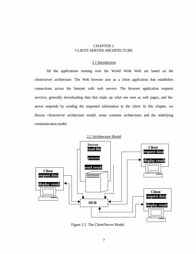
2.2 Architecture Model
Figure 2.1: The Client/Server Model
Server read file process send result
Client request data display result
Client request data display result
Client request data display result
HUB

8
Client-server architecture is an effective and popular design for distributed
applications. In the client server model, an application is split into two parts: the client
and the server. The client application is typically an application that runs on one machine,
requesting services from the server application that runs on another machine. The general
architecture of client/server model is shown in Figure 2.1.
2.3 Common Architectural Models
This section deals with different type of client/server architecture model and their
advantages and disadvantages.
Two-Tier Architectures
With two-tier client/server architectures, the user system interface is usually
located in the user's desktop environment and the backend resource (such as database
management services) is usually in a server that is a more powerful machine that services
many clients. Processing management is split between the client and the server
environment.
The two-tier client/server architecture is a good solution for distributed computing
when work groups are defined as a dozen to 100 people interacting on a LAN
simultaneously. It does have a number of limitations. When the number of users exceeds
100, performance begins to deteriorate [4]. This limitation is a result of the server
maintaining a connection via keep-alive messages with each client, even when no work is
being done. A second limitation of the two-tier architecture is implementation of
processing management services [4]. Finally, current implementations of the two-tier
architecture provide limited flexibility in moving (repartitioning) program functionality
from one server to another without manually regenerating procedural code.

9
Three-Tier Architectures
Three-tier architecture (also referred to as multi-tier architecture) emerged to
overcome the limitations of two-tier architecture. In three-tier architecture, a middle tier
was added between the client environment and the server environment. There are several
ways of implementing this middle tier, such as transaction processing monitors, message
servers, or application servers. The middle tier can perform queuing, application
execution, and database staging [4]. For example, if the middle tier provides queuing, the
client can deliver its request to the middle layer and disengage because the middle tier
accesses the data and returns the answer to the client. In addition the middle layer
schedules and prioritizes work in progress [4]. The three-tier client/server architecture has
been shown to improve performance for groups with a large number of users (in the
thousands) and improves flexibility when compared to the two-tier approach. A limitation
with three-tier architectures is that the development environment is reportedly more
difficult to use than the visually oriented development of two tier applications.
Three-Tier With An Application Server
Three-tier application server architecture allocates the main body of an
application to run on a shared host rather than in the client environment. The application
server does not drive the GUIs; rather it shares business logic, computations, and a data
retrieval engine. The advantages of this architecture are that the client has to worry less
about the security, applications are more scalable, and support and installation costs are
less on a single server than maintaining each on a desktop client. The application server
design should be used when security, scalability, and cost are major considerations [5].
10
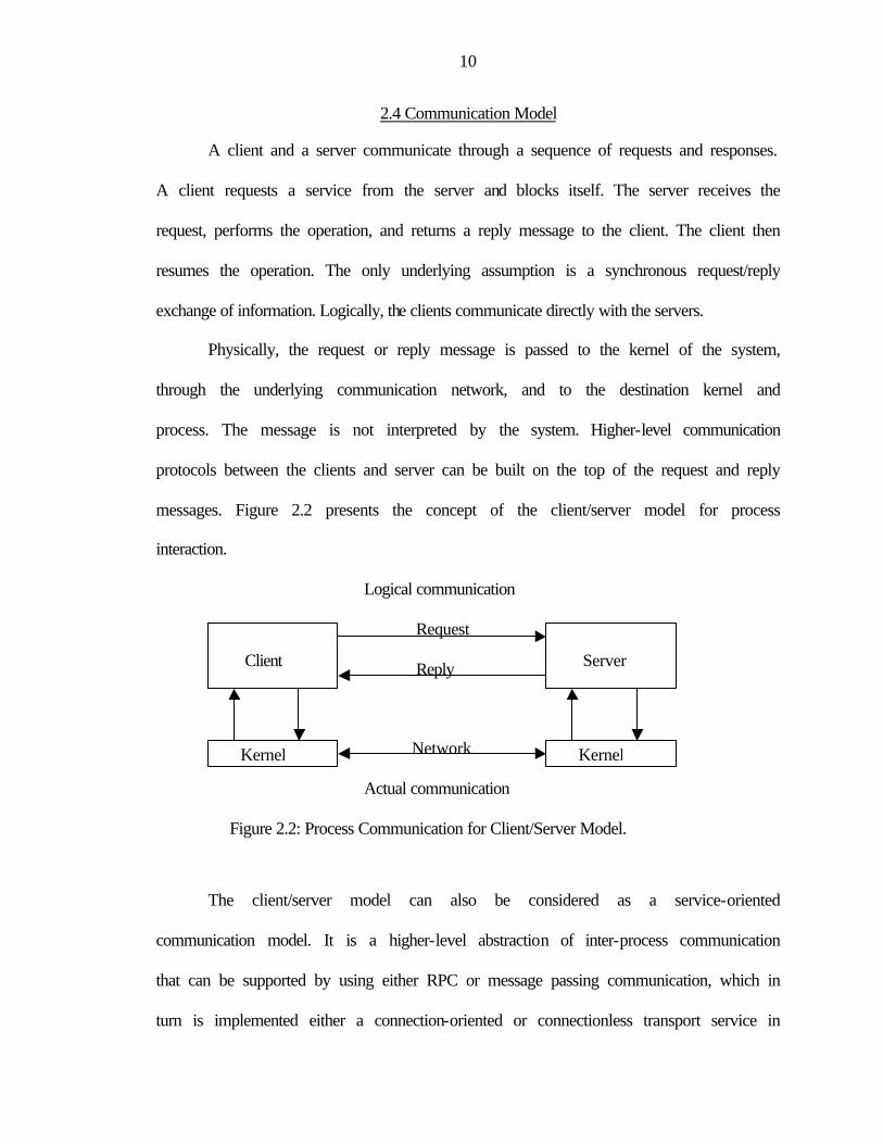
2.4 Communication Model
A client and a server communicate through a sequence of requests and responses.
A client requests a service from the server and blocks itself. The server receives the
request, performs the operation, and returns a reply message to the client. The client then
resumes the operation. The only underlying assumption is a synchronous request/reply
exchange of information. Logically, the clients communicate directly with the servers.
Physically, the request or reply message is passed to the kernel of the system,
through the underlying communication network, and to the destination kernel and
process. The message is not interpreted by the system. Higher-level communication
protocols between the clients and server can be built on the top of the request and reply
messages. Figure 2.2 presents the concept of the client/server model for process
interaction.
Logical communication
Request
Reply
Network
Actual communication
Figure 2.2: Process Communication for Client/Server Model.
The client/server model can also be considered as a service-oriented
communication model. It is a higher-level abstraction of inter-process communication
that can be supported by using either RPC or message passing communication, which in
turn is implemented either a connection-oriented or connectionless transport service in
Client
Server
Kernel Kernel
11
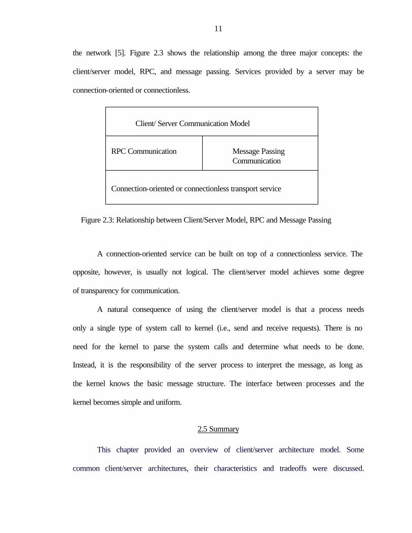
the network [5]. Figure 2.3 shows the relationship among the three major concepts: the
client/server model, RPC, and message passing. Services provided by a server may be
connection-oriented or connectionless.
Figure 2.3: Relationship between Client/Server Model, RPC and Message Passing
A connection-oriented service can be built on top of a connectionless service. The
opposite, however, is usually not logical. The client/server model achieves some degree
of transparency for communication.
A natural consequence of using the client/server model is that a process needs
only a single type of system call to kernel (i.e., send and receive requests). There is no
need for the kernel to parse the system calls and determine what needs to be done.
Instead, it is the responsibility of the server process to interpret the message, as long as
the kernel knows the basic message structure. The interface between processes and the
kernel becomes simple and uniform.
2.5 Summary
This chapter provided an overview of client/server architecture model. Some
common client/server architectures, their characteristics and tradeoffs were discussed.
Client/ Server Communication Model
RPC Communication Message Passing Communication Connection-oriented or connectionless transport service

12
The three-tier architecture provides (when compared to the two tier) increased
performance, flexibility, maintainability, reusability, and scalability, while hiding the
complexity of server side processing and implementation details from the user. These
characteristics have made three layer architectures a preferred choice for the development
of web-enabled interface for the electronic book.
13
CHAPTER 3 FUNDAMENTAL SYSTEM COMPONENTS
3.1 Introduction
In the previous chapter, a brief overview of client/server architecture was given.
In this chapter we shall discuss underlying technologies and system components that have
been used as building blocks for the three-tier architecture model for web based graphical
interface for the interactive electronic book. Applet, Servlet, Java Native Interface,
Applet-Servlet Communication, NeuroSolutions™ are briefly covered in this chapter.
3.2 Java Native Interface
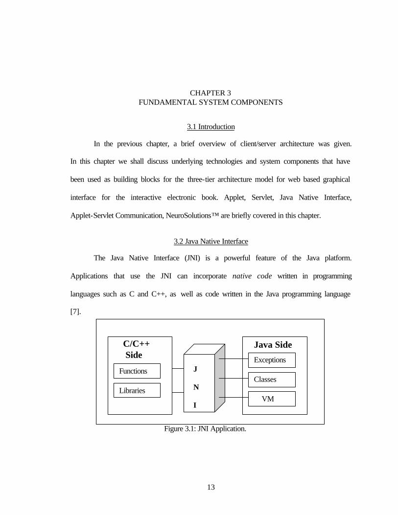
The Java Native Interface (JNI) is a powerful feature of the Java platform.
Applications that use the JNI can incorporate native code written in programming
languages such as C and C++, as well as code written in the Java programming language
[7].
Figure 3.1: JNI Application.
Java Side
J N I
C/C++ Side
Functions
Libraries
Exceptions
Classes
VM
14
The JNI allows programmers to take advantage of the java platform, without
having to abandon code written in C/C++. Because the JNI is an essential part of the java
platform, interoperability issues can be addressed once, and expect their solution to work
with all implementations of the java platform. The following Figure 3.1 shows how the
JNI links the Java program to a C/C++ program.
The Java Platform and Host Environment
The java platform is a programming environment consisting of the Java Virtual
Machine (JVM) and the Java Application Interface (API). Java applications are written in
the Java programming language, and compiled into machine-independent byte codes.
The term host environment represents the host operating system, a set of native
libraries, and the CPU instruction set. Native applications are written in native
programming languages such as C and C++, compiled into host specific binary code, and
linked with native libraries. Native applications and native libraries are typically
dependent on a particular host environment. A C/C++ application built for one operating
typically doesn’t work on other operating system [7].
Java platform is commonly deployed on top of a host environment. For example,
the Java Runtime Environment (JRE) is a Sun product and that supports the Java platform
on existing operating systems such as Solaris and Windows. The java platform offers a
set of features that applications can rely on independent of the underlying host
environment.
Role of the JNI
When the Java platform is deployed on top of host environments, it may become
essential to allow Java applications to work closely with native code written in other
15
languages [8]. Programmers have begun to adopt Java platform to build applications that
were traditionally written in C and C++.
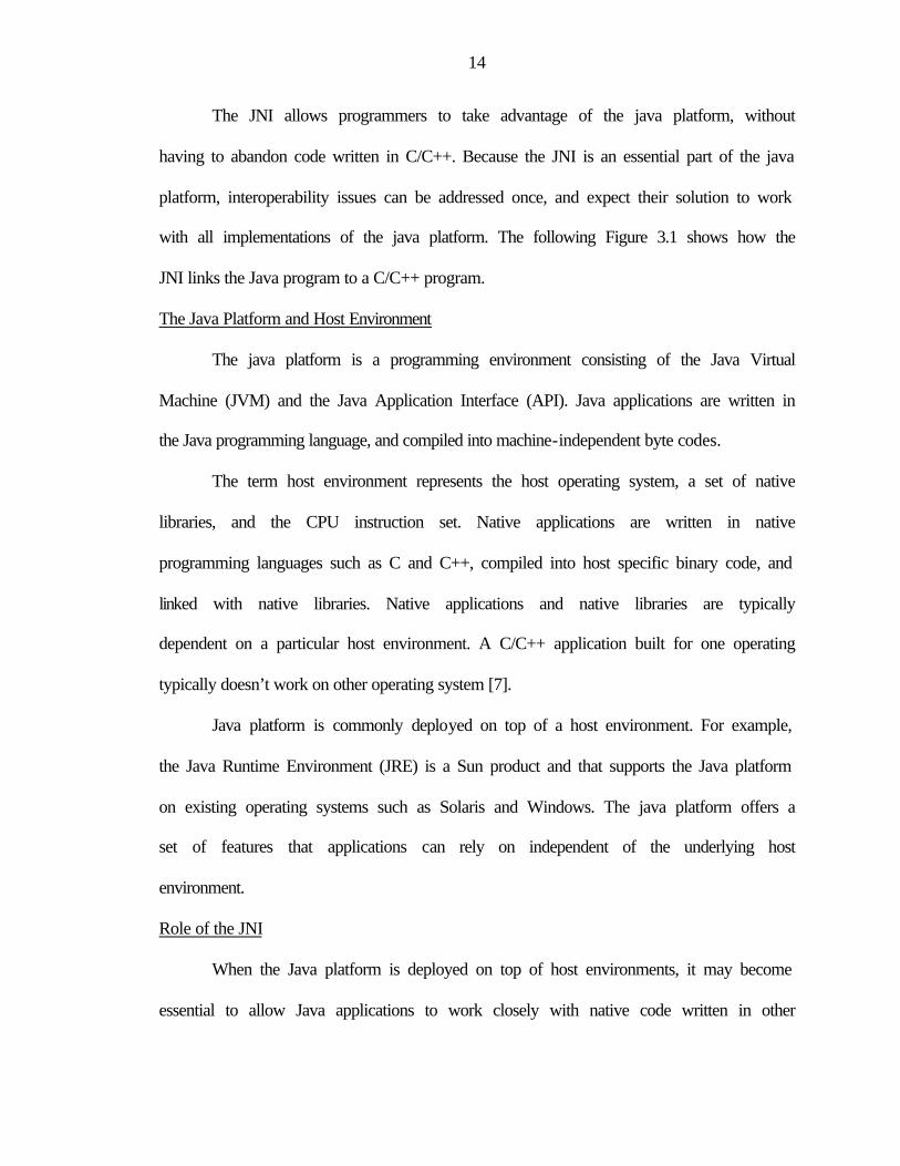
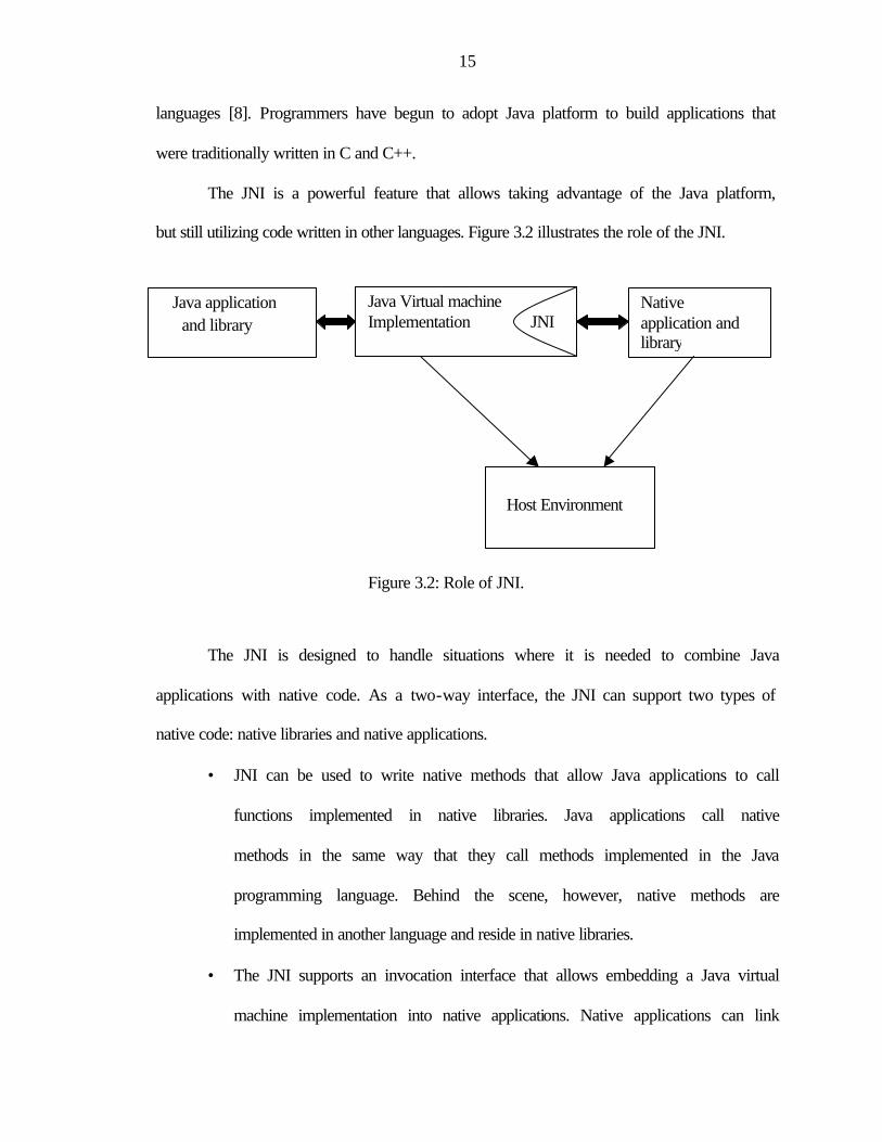
The JNI is a powerful feature that allows taking advantage of the Java platform,
but still utilizing code written in other languages. Figure 3.2 illustrates the role of the JNI.
Figure 3.2: Role of JNI.
The JNI is designed to handle situations where it is needed to combine Java
applications with native code. As a two-way interface, the JNI can support two types of
native code: native libraries and native applications.
• JNI can be used to write native methods that allow Java applications to call
functions implemented in native libraries. Java applications call native
methods in the same way that they call methods implemented in the Java
programming language. Behind the scene, however, native methods are
implemented in another language and reside in native libraries.
• The JNI supports an invocation interface that allows embedding a Java virtual
machine implementation into native applications. Native applications can link
Java application and library
Java Virtual machine Implementation JNI
Native application and library
Host Environment
16
with a native library that implements the java virtual machine, and then use
the invocation interface to execute software components written in the Java
programming language.
Implications of Using the JNI
First, Java applications that depend on the JNI can no longer readily run over
multiple host environments. Even though the part of an application written in the Java
programming language is portable to multiple host environments, it will be necessary to
recompile the part of the application written in native programming languages.
Secondly, while the Java programming language is type-safe and secure, native
languages such as C, C++ are not [7]. As a result one must use extra care when writing
application using JNI. A misbehaving native method can corrupt the entire application.
For, this reason Java applications are subject to security checks before invoking native
features.
3.3 Applet
Java applets are essentially Java programs that run within a web page. They are
Java classes that extend the java.applet.Applet class and are embedded by reference
within an HTML page, much like an image. Combined with HTML, they can make an
interface more dynamic and powerful than with HTML alone.
Besides the class file defining the Java applet itself, applets can use a collection of
utility classes, either by themselves or archived into a JAR file. The applets and their
class files are distributed through standard HTTP requests and therefore can be sent
across firewalls with the rest of the web page data. Applet code is refreshed automatically
17
each time the user revisits the hosting web site, eliminating the concern of keeping the
full application up to date on each client desktop to which it’s been distributed.
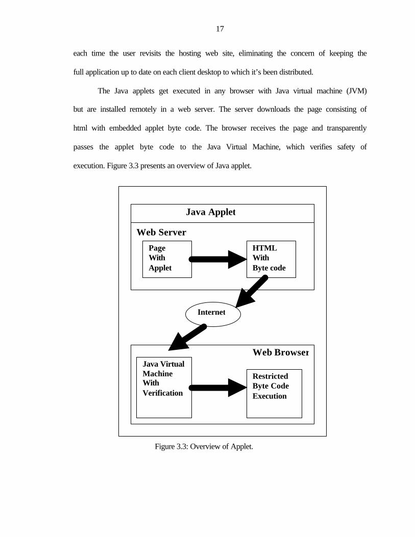
The Java applets get executed in any browser with Java virtual machine (JVM)
but are installed remotely in a web server. The server downloads the page consisting of
html with embedded applet byte code. The browser receives the page and transparently
passes the applet byte code to the Java Virtual Machine, which verifies safety of
execution. Figure 3.3 presents an overview of Java applet.
Figure 3.3: Overview of Applet.
Java Applet
Web Server Page
With Applet
HTML With Byte code
Internet
Web Browser
Java Virtual Machine With Verification
Restricted Byte Code Execution
18
Applets have all the functionality of a traditional Java application, including the
ability to use advanced JFC/Swing components from SUN. Applets have the full
graphical and user interface capability of applications. But despite their similarities, there
are some key differences between applications and applets such as security constraints.
Advantages of Applets
Applet provides, in effect, an automatic install, and is very effective for naïve
end-users. They do not require the downloading of java to the end-user machine as they
use Java environment of the end-user’s browser. Each CLASS or JAR file is downloaded
only as needed, can be cached inside the browser to avoid the expensive download
operation. Applets are inherently graphical, more secure and multithreaded.
Disadvantages of Applets
A major disadvantage with applets is that the download size of the CLASS or
JAR file can be very large. Even if the JAR files are small, the browser must read the
JAR file, which can cause poor performance over slow dial-up lines. The JAR is about
the size of a normal graphic image and is stored in the browser's cache. While caching
can be helpful, it can cause problems if multiple version of a single applet occupies the
cache at the same time. In addition, applets offer no means of rolling back to an older
version. If there is an update, the entire new applet must be downloaded, even if caching
is used, because applets provide no JAR differencing.
The most serious applet problem, however, is the complete lack of control over
the end user’s environment. Using the browser’s Java environment is a mixed blessing. It
avoids a costly download, but it exposes software developers to a huge testing and
19
maintenance task. The variety of browsers and JDKs is seemingly infinite, and every
combination pose potential issues. The task of detecting and handling these environments
can be extremely taxing for certain applications. There is no guarantee that an applet will
run correctly. If Internet access is interrupted, a partial or damaged class file can be
downloaded. Unfortunately, the applet model doesn’t provide any way to heal a damaged
install, or to continue a partial install.
Applets provide no true integration with the desktop. They must always be run in
the browser, cannot be launched from the desktop, and cannot support the download of
anything except java. class or .jar file.
Security Constraints on Applets
Applet code is served from a host web server and executed in the client’s browser
on the end user’s machine. To prevent proliferation of malicious applets that could wreak
havoc on unsuspecting surfers, applets are bound by security constraints that allow them
to communicate only with their host server and prevent them from interacting with the
end user’s machine.
Current browsers impose the following restrictions on any applet that is loaded
over the network:
• It cannot load libraries or define native methods.
• It cannot ordinarily read or write files on the host that's executing it.
• It cannot make network connections except to the host that it came from.
• It cannot start any program on the host that's executing it.
• It cannot read certain system properties.
20
But there actually is a way around this – the developer can sign the applet code
with a digital signature, which will then trigger the browser to ask the user for specific
privileges otherwise would not be granted.
Because of these restrictions, we must employ special strategies to communicate
information to or from applet. The only avenue of communication is the network
connection between the local server on which the applet resides and the host serving the
HTML that reverences the applet. This gives us a way to build real-time interactive
interface that can use web as their platform.
3.4 Servlet Technologies
Servlets are protocol and platform independent server side components, written in
Java, which dynamically extend Java enabled servers [8]. They provide a general
framework for services built using the client-server paradigm. Their initial use is to
provide secure web-based access to data, which is presented using HTML web pages and
interactively viewing or modifying that data. Since servlet run inside servers, they do not
need a graphical user interface. Otherwise, they are the server side counterparts of the
applets (which are used only on the client side of systems).
Functions of Servlet
• Create and return an entire HTML page containing dynamic content based on
the nature of the client request.
• Create a portion of an HTML page (an HTML fragment) that can be
embedded in an existing HTML page.
• Communicate with other server resources, including databases and Java-based
applications.
21
• Communicate with other servlets.
• Handle connections with multiple clients, accepting input from and
broadcasting results to the multiple clients.
Servlet Capabilities
• Servlets are fast. It loads into memory once, and run from memory thereafter.
• Servlets are spawned as a thread, not a process.
• Servlets are multithreaded in their own right.
• Servlets are simple to implement.
• Servlets are Java byte code and therefore platform independent by nature.
Architectural Roles for Servlets
Servlets can play a significant role in system architecture because of their power
and flexibility. They can perform the application processing assigned to the middle tier,
act as a proxy for client, and even augment the features of the middle tier by adding
support for new protocols or other features [9]. A middle tier acts as the application
server in so-called three-tier client/server systems, positioning itself between a
lightweight client such as a web browser and a backend data source.
Middle-Tier Process
In many systems a middle tier serves as a link between clients and back-end
services. By using the middle tier a lot of processing can be off-loaded from both the
clients (making them lighter and faster) and servers (allowing them to focus on their
mission). One advantage of middle tier processing is simply connection management. A
set of servlets could handle connections with hundreds of clients while recycling a pool
of expensive connection to back-end services.
22
Other middle tier roles include business management, transaction management,
mapping clients to a redundant set of servers and supporting different types of clients
such as pure HTML and java capable clients.
Proxy Servers
When used to support applets, servlets can act as their proxies. This can be
important because Java security allows applets only to make connections back to server
from which they are loaded.
If an applet needs to connect to a database server/backend resource located on a
different machine, a servlet can make this connection on behalf of the applet.
Protocol Support
The Servlet API provides a link between a server and services. This allows
servlets to add new protocol support to a server. Essentially, any protocol that follows a
request/response computing model can be implemented by a servlet.
Servlet support is currently available in several web servers, and will probably
start appearing in other types of application servers in the near future. A web server will
be used to host the servlets and will deal only with HTTP protocol.
Because HTTP is one of the most common protocols, and because HTML can
provide such a rich presentation of information, servlets probably contribute the most to
building HTTP based systems.
HTML Support
HTML can provide a rich presentation of information because of its flexibility
and the range of content that it can support. Servlets can play a role in creating HTML
23
content. In fact, servlet support for HTML is so common; the javax.servlet.http package
is dedicated for supporting HTTP protocol and HTML generation [9].
Complex web sites often need to provide HTML pages that are tailored for each
visitor, or even for each hit. Servlets can be written to process HTML pages and
customize them as they are sent to a client. This can be as simple as on the fly
substitution or it can be as complex as compiling a grammar-based description of a page
and generating custom HTML.
Servlet Security Features
Servlets have access to information about their clients. When used with secure
protocols such as SSL, peer identities can be determined reliably. Servlets relying on
HTTP also have access to HTTP specific authentication data.
Servlets have the advantages, memory access violations and strong typing
violations are not possible, so that faulty servlets will not crash servers the way that is
common in most C language server extension environments.
Unlike any other current server extension API, Java Servlets provide strong
security policy support. This is because all the Java environments provide a Security
Manager, which can be used to control whether actions such as network or file access are
to be permitted [8]. By default, all servlets are not trusted, and are not allowed to perform
operations such as accessing network services or local files.
However, servlet built in to the server, or servlets, which have been digitally
signed as they were put into Java Archive (JAR) files, may be trusted and granted more
permission by the security manager. A digital signature on executable code indicates that
the organization which signed the code “vouches for it” in some sense. Such signature
24
cannot support accountability by them, but they do indicate a degree of assurance that
may be placed on use of that code.
Java Server
Native Code Libraries
Unsigned Servlets Signed Servlets
Figure 3.4: Servlet Security Features
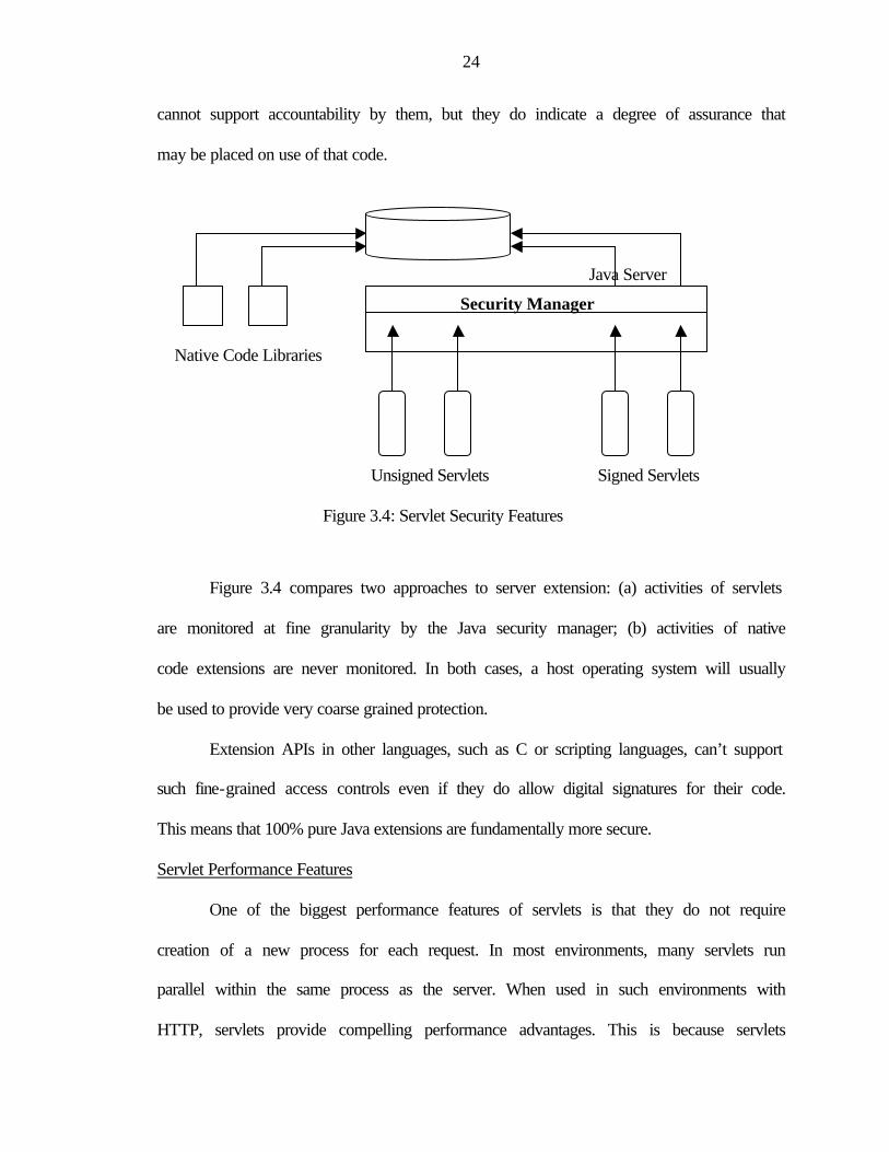
Figure 3.4 compares two approaches to server extension: (a) activities of servlets
are monitored at fine granularity by the Java security manager; (b) activities of native
code extensions are never monitored. In both cases, a host operating system will usually
be used to provide very coarse grained protection.
Extension APIs in other languages, such as C or scripting languages, can’t support
such fine-grained access controls even if they do allow digital signatures for their code.
This means that 100% pure Java extensions are fundamentally more secure.
Servlet Performance Features
One of the biggest performance features of servlets is that they do not require
creation of a new process for each request. In most environments, many servlets run
parallel within the same process as the server. When used in such environments with
HTTP, servlets provide compelling performance advantages. This is because servlets
Security Manager
25
only require lightweight thread context switches. Since in most environments servlets can
handle many client requests each time they are initialized, the costs of the initialization
are spread over many methods. All the clients request to that service have the opportunity
to share data and communication resources, benefiting more strongly from system
caches.
With many implementations of the Java Virtual Machine (JVM), Java Servlet
programs automatically take advantage of additional processors, helping to scale
applications up from entry-level servers all the way up to mainframe class
multiprocessors. This helps provide better throughput and response time to the clients.
Using Java servlets in web-based applications Servlets can be key component in many
large applications leveraging Java and other Internet technologies.
3.5 Applet-Servlet Communication
Most of the time, servlets and applets shouldn't talk to each other. These two
types of Java programs live in different worlds: servlets live in the world of HTTP, while
applets live in a more "pure" Java environment. Applets are, by definition, embedded
within a context: the browser. It is the browser that generally issues requests to the
servlet. In general, the servlet class sends notifications relating these requests to other
Java objects on the server and then writes an HTML page with some information relating
to the state of the other Java objects. This may seem like hair-splitting, but in fact it's an
important point: applets and servlets generally talk only indirectly.
26
Architectural Options for Applet-Servlet Communication
An enterprise application that makes use of applets and servlets can conceivably
be designed in more than one way. I'll outline three different architectural options here
and describe their drawbacks and advantages.
Two-tier Application Architecture
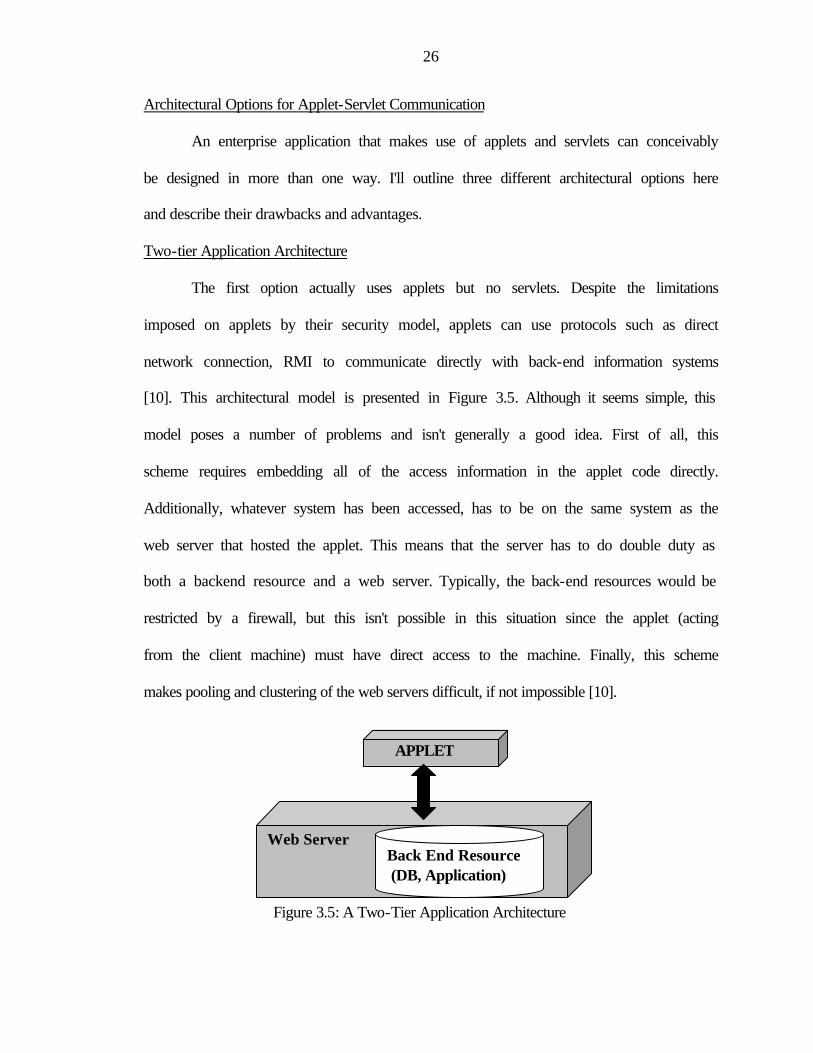
The first option actually uses applets but no servlets. Despite the limitations
imposed on applets by their security model, applets can use protocols such as direct
network connection, RMI to communicate directly with back-end information systems
[10]. This architectural model is presented in Figure 3.5. Although it seems simple, this
model poses a number of problems and isn't generally a good idea. First of all, this
scheme requires embedding all of the access information in the applet code directly.
Additionally, whatever system has been accessed, has to be on the same system as the
web server that hosted the applet. This means that the server has to do double duty as
both a backend resource and a web server. Typically, the back-end resources would be
restricted by a firewall, but this isn't possible in this situation since the applet (acting
from the client machine) must have direct access to the machine. Finally, this scheme
makes pooling and clustering of the web servers difficult, if not impossible [10].
Figure 3.5: A Two-Tier Application Architecture
APPLET
Web Server Back End Resource (DB, Application)
27
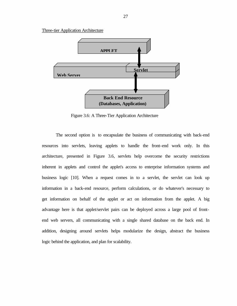
Three-tier Application Architecture
Figure 3.6: A Three-Tier Application Architecture
The second option is to encapsulate the business of communicating with back-end
resources into servlets, leaving applets to handle the front-end work only. In this
architecture, presented in Figure 3.6, servlets help overcome the security restrictions
inherent in applets and control the applet's access to enterprise information systems and
business logic [10]. When a request comes in to a servlet, the servlet can look up
information in a back-end resource, perform calculations, or do whatever's necessary to
get information on behalf of the applet or act on information from the applet. A big
advantage here is that applet/servlet pairs can be deployed across a large pool of front-
end web servers, all communicating with a single shared database on the back end. In
addition, designing around servlets helps modularize the design, abstract the business
logic behind the application, and plan for scalability.
APPLET
Servlet Web Server
Back End Resource (Databases, Application)
28
Applet-Servlet Communication techniques
Three techniques allow applets and servlets to communicate: HTML manipulation
(this involves dynamically writing HTML and rewriting the active URL), using the
java.net packages to create a direct network connection and invoking a remote method
using Java's remote method invocation (RMI) interface. Here we will review each of
these techniques.
HTML Manipulation
The most common way for a servlet to communicate with an applet is HTML
manipulation. The easiest way for a servlet to manipulate an applet is for the servlet to
simply write whatever information it needs to pass to the servlet within the HTML it
generates. The servlet dynamically generates PARAM tags containing data to pass to the
applet.
The disadvantages of this technique are two-fold. First, the data is static. Once the
HTML page is written updated data can't be passed to the servlet. HTTP's refresh
mechanism (that is, use either server-side push or client-side pull to re-request the URL
after a few seconds) can be used, but this requires reloading the entire page and cannot be
done very swiftly. Secondly, the technique is also inappropriate for use with large
amounts of data. As long as there are few parameters it's fine, but if number of
parameters are very large, or data structure is complex, the HTML page becomes very
difficult to load.
Two-Way Talk with Java.net
The second technique is to use the java.net package's networking capabilities. In
this situation the applet does not speak directly with the servlet. Rather, the servlet creates
29
a listener class during initialization. This listener class creates a Server Socket and listens
for incoming connections from the applet. When an incoming connection is received, the
listener class hands off the data connection to a third class, the server-side data provider
class, which communicates with the servlet using Java's standard IO library.
The servlet uses the HTML-rewriting technique in order to send down the precise
address of the port on which the servlet listener class is listening [11]. The applet opens
up a socket and attempts to connect to the listening class. The java.net technique is quite
clean and fairly easy to implement. Because it relies on nothing more than Java's standard
network interfaces, it's easy to modify for a particular need. On the other hand, various
requests have to be parsed for information coming in at the server side and then, on the
client side, interpret the results coming back.
RMI Bootstrapping
Java's RMI technology significantly increases the ability to work with complex
server-side objects. To the applet, a server-side object looks like a regular client-side
handle. This technique relies on object-oriented polymorphism. RMI starts with the
definition of an interface. A public interface is defined that extends java.rmi.Remote and
specifies the required methods running on the server. Each declared method must be
defined as throwing java.rmi.RemoteException in addition to whatever other exceptions
it propagates.
The next step is to write a class that extends UnicastRemoteObject and
implements the interface. In addition, this class must have a default (no argument)
constructor that is defined as throwing RemoteException. In addition to compiling the
implementation class, the class file must be passed as an argument to the rmic tool. This

30
tool creates two more Java classes. RMIImplementation_Stub.class will be packaged with
the applet and will run on the client. RMIImplementation_Skel.class will be packaged
with the servlet and will run on the server. However, the code should not contain direct
references to these classes. Rather, client-side code will have a reference to the interface,
in this case RMIServ2App. That reference is produced by the static method
Naming.lookup(String).
Now that the implementation has been created and the registry has been started,
an instance of the object needs to be created and installed into the registry as a
"bootstrap" object associated with a particular name. This needs to be done in the main()
method of RMIImplementation. So the sequence to get RMI up and running is: start the
registry, run RMIImplementation, and start the Web server.
RMI is appropriate for situations where there is either dynamic or large data
provided by Java objects on the server [11]. Although RMI does allow for OO distributed
programming, it is only supported when both client and server are written in Java. If
application demands mixed language development, RMI will not be sufficient.
3.6 Web Server
A Web Server is a computer with special software to host web pages and web
applications. Web server's traditional function has been to serve static HTML (and more
recently XML) pages. As the Internet has become more functional, i.e. e-commerce and
dynamic sites, increasing emphasis is placed on a servers ability to host web applications.
Many different servers are in use on the Internet. Unlike the browser, the server
has the capacity to handle processing request from multiple clients scattered locally and
around the world and it has the software tools and information methods necessary to

31
handle these request. Some of the more popular web servers ones are Apache and Internet
Information Server (IIS).
3.7 NeuroSolutions™
NeuroSolutions™ is a NeuroDimension product. This leading edge software
combines a modular, icon-based network design interface with an implementation of
advanced learning procedures, such as recurrent back propagation and back propagation
through time. Some other notable features include C++ source code generation,
customized components through DLLs, a comprehensive macro language, and Visual
Basic accessibility through OLE Automation [3].
NeuroSolutions™ is based on an object-oriented approach to adaptive system
design. The networks are broken down into a fundamental set of components that are
individually simple but can be combined together to build neural networks capable of
solving complex problems. Every neural component within NeuroSolutions is
implemented as a C++ object and is self-contained [1]. Due to its object-oriented nature,
NeuroSolutions™ specifies what components do and how components interact with each
other.
NeuroSolutions™ provide users with powerful neural network building
capabilities. Creating neural networks is fast and easy with NeuroSolutions™. Neural
components, such as axons, synapses, and gradient search engines, are laid out on a
graphical breadboard and connected together to form a neural network. NeuroSolutions
also provide inspector for each neural network component. Inspector is a window that
provides access to the parameters of a neural network component. The user can configure
any network component during training or testing by modifying these parameters.
32
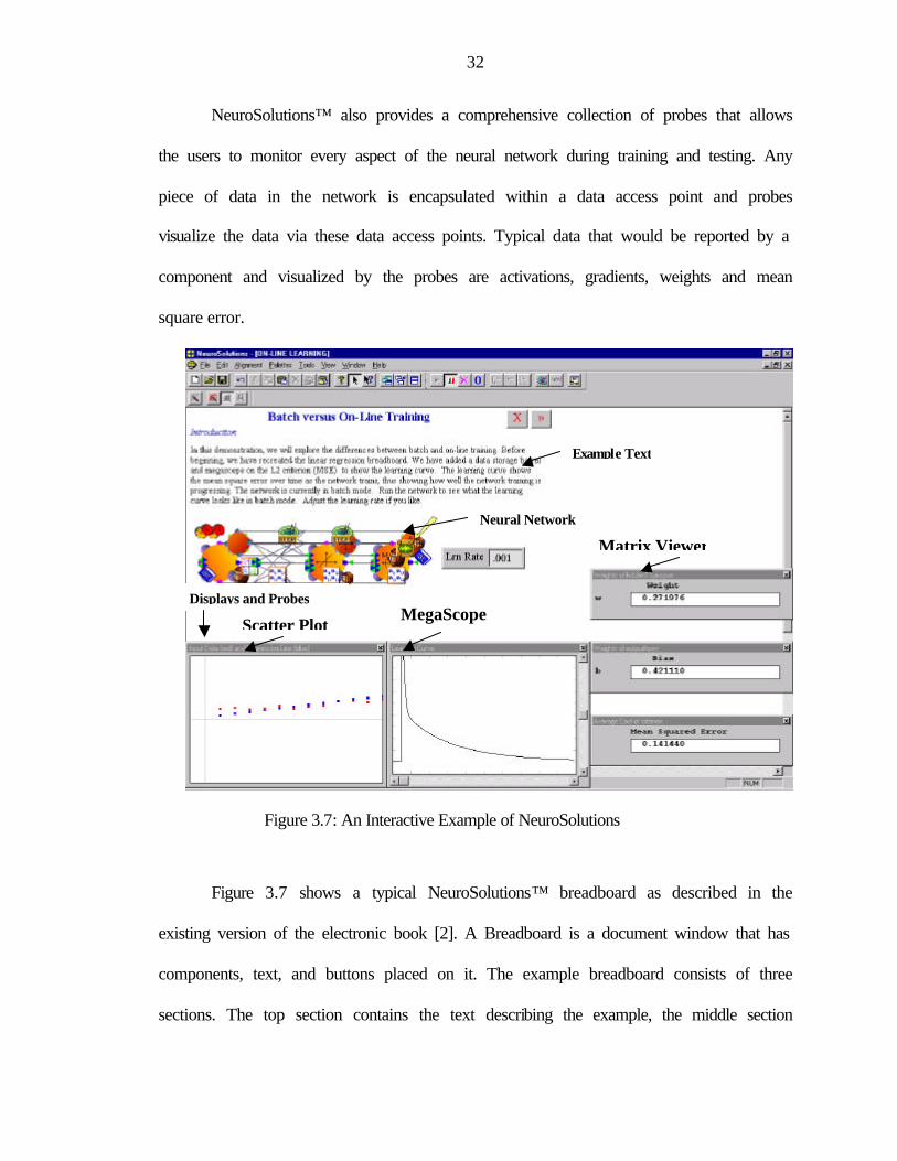
NeuroSolutions™ also provides a comprehensive collection of probes that allows
the users to monitor every aspect of the neural network during training and testing. Any
piece of data in the network is encapsulated within a data access point and probes
visualize the data via these data access points. Typical data that would be reported by a
component and visualized by the probes are activations, gradients, weights and mean
square error.
Figure 3.7: An Interactive Example of NeuroSolutions
Figure 3.7 shows a typical NeuroSolutions™ breadboard as described in the
existing version of the electronic book [2]. A Breadboard is a document window that has
components, text, and buttons placed on it. The example breadboard consists of three
sections. The top section contains the text describing the example, the middle section
Scatter Plot MegaScope
Matrix Viewer
Example Text
Neural Network
Displays and Probes
33
contains the components that make up the neural network example, and the bottom
section contains the various displays or graphs that “probe” the network. The interactive
examples are created on the fly using interactive macros in NeuroSolutions™. We will
now discuss different aspects of interactive examples of NeuroSolutions™.
Neural Components
Each interactive example of neural network is composed of neural components,
each with specific functionality. These networks primarily consist of processing elements
(PEs) tied together with weighted connections. The Axon family of components
implements the PEs in the network, and the Synapse family implements the weighted
connections.
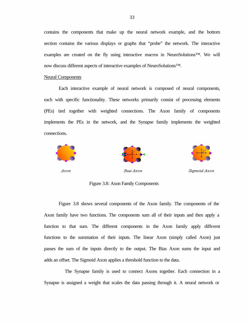
Figure 3.8: Axon Family Components
Figure 3.8 shows several components of the Axon family. The components of the
Axon family have two functions. The components sum all of their inputs and then apply a
function to that sum. The different components in the Axon family apply different
functions to the summation of their inputs. The linear Axon (simply called Axon) just
passes the sum of the inputs directly to the output. The Bias Axon sums the input and
adds an offset. The Sigmoid Axon applies a threshold function to the data.
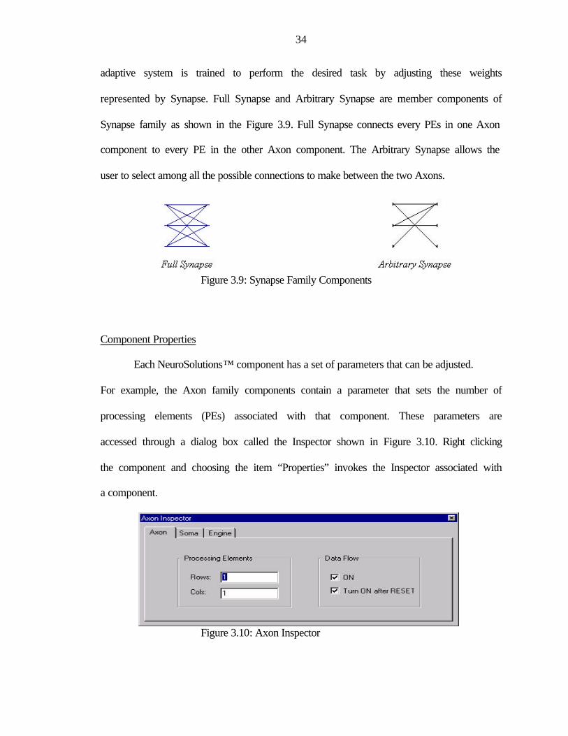
The Synapse family is used to connect Axons together. Each connection in a
Synapse is assigned a weight that scales the data passing through it. A neural network or
34
adaptive system is trained to perform the desired task by adjusting these weights
represented by Synapse. Full Synapse and Arbitrary Synapse are member components of
Synapse family as shown in the Figure 3.9. Full Synapse connects every PEs in one Axon
component to every PE in the other Axon component. The Arbitrary Synapse allows the
user to select among all the possible connections to make between the two Axons.
Figure 3.9: Synapse Family Components
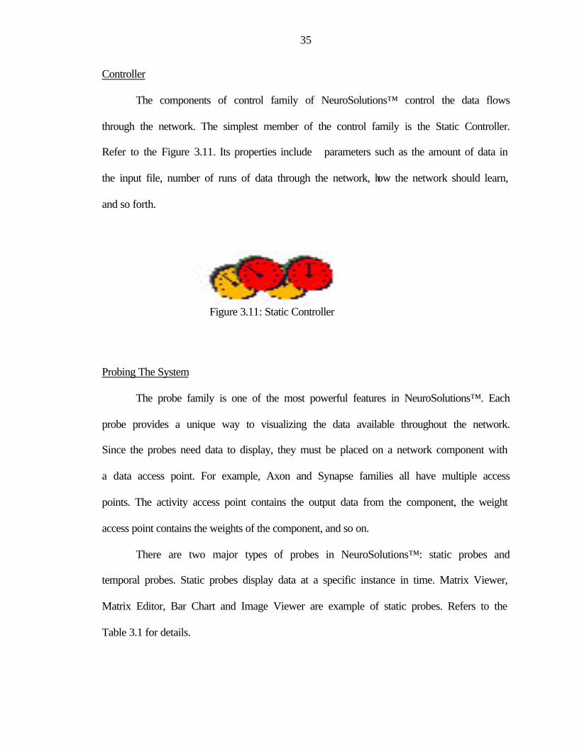
Component Properties
Each NeuroSolutions™ component has a set of parameters that can be adjusted.
For example, the Axon family components contain a parameter that sets the number of
processing elements (PEs) associated with that component. These parameters are
accessed through a dialog box called the Inspector shown in Figure 3.10. Right clicking
the component and choosing the item “Properties” invokes the Inspector associated with
a component.
Figure 3.10: Axon Inspector
35
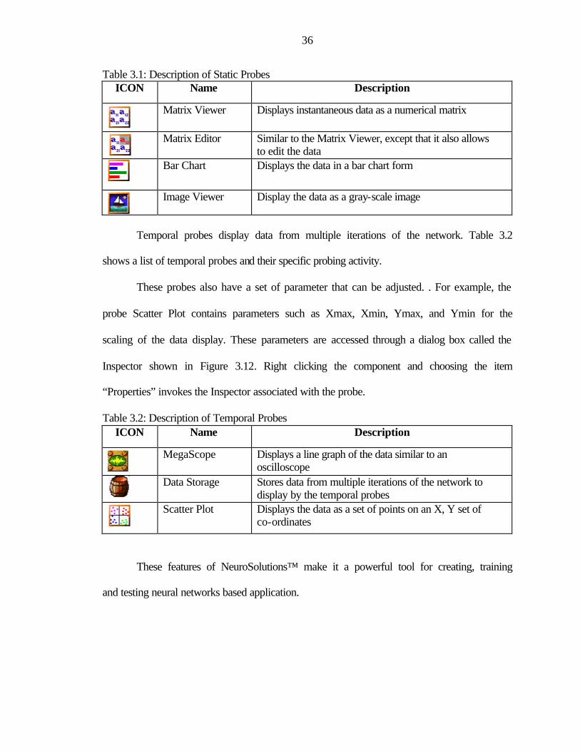
Controller
The components of control family of NeuroSolutions™ control the data flows
through the network. The simplest member of the control family is the Static Controller.
Refer to the Figure 3.11. Its properties include parameters such as the amount of data in
the input file, number of runs of data through the network, how the network should learn,
and so forth.
Figure 3.11: Static Controller
Probing The System
The probe family is one of the most powerful features in NeuroSolutions™. Each
probe provides a unique way to visualizing the data available throughout the network.
Since the probes need data to display, they must be placed on a network component with
a data access point. For example, Axon and Synapse families all have multiple access
points. The activity access point contains the output data from the component, the weight
access point contains the weights of the component, and so on.
There are two major types of probes in NeuroSolutions™: static probes and
temporal probes. Static probes display data at a specific instance in time. Matrix Viewer,
Matrix Editor, Bar Chart and Image Viewer are example of static probes. Refers to the
Table 3.1 for details.
36
Table 3.1: Description of Static Probes ICON Name Description
Matrix Viewer Displays instantaneous data as a numerical matrix
Matrix Editor Similar to the Matrix Viewer, except that it also allows
to edit the data
Bar Chart Displays the data in a bar chart form
Image Viewer Display the data as a gray-scale image
Temporal probes display data from multiple iterations of the network. Table 3.2
shows a list of temporal probes and their specific probing activity.
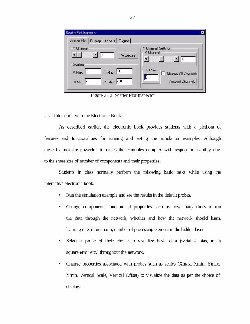
These probes also have a set of parameter that can be adjusted. . For example, the
probe Scatter Plot contains parameters such as Xmax, Xmin, Ymax, and Ymin for the
scaling of the data display. These parameters are accessed through a dialog box called the
Inspector shown in Figure 3.12. Right clicking the component and choosing the item
“Properties” invokes the Inspector associated with the probe.
Table 3.2: Description of Temporal Probes ICON Name Description
MegaScope Displays a line graph of the data similar to an
oscilloscope
Data Storage Stores data from multiple iterations of the network to
display by the temporal probes
Scatter Plot Displays the data as a set of points on an X, Y set of
co-ordinates
These features of NeuroSolutions™ make it a powerful tool for creating, training
and testing neural networks based application.
37
Figure 3.12: Scatter Plot Inspector
User Interaction with the Electronic Book
As described earlier, the electronic book provides students with a plethora of
features and functionalities for running and testing the simulation examples. Although
these features are powerful, it makes the examples complex with respect to usability due
to the sheer size of number of components and their properties.
Students in class normally perform the following basic tasks while using the
interactive electronic book.
• Run the simulation example and see the results in the default probes.
• Change components fundamental properties such as how many times to run
the data through the network, whether and how the network should learn,
learning rate, momentum, number of processing element in the hidden layer.
• Select a probe of their choice to visualize basic data (weights, bias, mean
square error etc.) throughout the network.
• Change properties associated with probes such as scales (Xmax, Xmin, Ymax,
Ymin, Vertical Scale, Vertical Offset) to visualize the data as per the choice of
display.
38
So, this is the minimum functionality provided to the users. As said earlier,
NeuroSolutions™ provides a complete control of the user interface and neural networks
but is complex for a novice. It is much better to provide the users with the functionalities
that are more frequently accessed, simple, easy to use and understand without loosing the
fundamental details. These features have been kept in mind while developing the web-
enabled interface of the electronic book.
3.8 Summary
This chapter provided an overview of underlying technologies used in the
development for the web based graphical interface for the interactive electronic book.
Applet, in combination with HTML, provides a platform independent, dynamic and
powerful client side user interface that runs within a web page. Servlet provides a
multithreaded, platform independent middle layer for secure web-based accesses to data.
NeuroSolutions ™ C++ core has been used as the core layer for the processing of data for
simulations. Java Native Interface allows interaction between Java applications and
functions already implemented in NeuroSolutions™ native libraries. Addition to this, we
also discussed the various components of the NeuroSolutions™, which are active part of
interactive electronic book.
39
CHAPTER 4 SYSTEM DESIGN AND IMPLEMENTATION
4.1 Introduction
This chapter discusses the underlying details for web-enabled interface of the
electronic book from a programmer perspective. In the Section 4.2 of this chapter, system
design issues and considerations for the web-enabled interface have been discussed. Later
in this chapter, the underlying system architecture, system logical flow, communication
tactics between system components and step-by-step system implementation process
have been explained in details.
4.2 System Design
In this section, we shall discuss fundamental design issues and considerations for
the web-enabled interface for the interactive electronic book. It also discusses the features
of the interactive electronic we preserved and their tradeoffs.
Design Considerations
The foremost design goal of this thesis was to develop an interface to overcome
the limitation of platform dependency of the present electronic book. As said earlier, the
interactive electronic book runs only on Windows 95 (or higher) or Windows NT. Java
platform was an obvious choice for the design and development of the user interface
because this is the most popular technology available today to create binary executables
that will run unchanged on multiple platforms without worrying about underlying
hardware and operating system.
40
As discussed in Chapter 1, the interactive electronic book also suffers from the
limitation of local nature of delivery (CD-ROM based). This limitation leads us to design
a web-enabled interface because platform independence and distributed features are
inherent to the Java enabled web browser. These characteristics of web-enabled interface
allow an easy and transparent access of remote documents and data. Java has extensive
set of programming APIs for designing and developing web-enabled interface. Java
Applets, JFC Swing component, together when combined with HTML, provides a
dynamic and powerful web enabled user interface.
The next most important design issue was the development of communication
protocols between web enabled user interface and NeuroSolutions™. There are two
possible design approaches.
Approach 1
The first design approach is to rewrite the whole NeuroSolutions™ core C++
programs in Java to make it compatible with the web-enabled interface. This alternative
is not acceptable because re-writing the whole NeuroSolutions™ programs in Java will
require considerable amount of time and efforts. This will also prohibits the reusability of
this simulation software, which was developed over five years period with significant
amount of time, effort and money. This motivated us to find an interface or technique
which will provide communication between Java interface and NeuroSolutions™ C++
programs.
41
Approach 2
The second design approach is to use Java Native Interface (JNI) technique to
provide a communication link between Java interface and NeuroSolutions™ C++
programs.
Java Native Interface is a powerful feature of the Java platform, which allows an
application or programs written in Java to utilize code written in C, C++. This way JNI
allows programmer to take advantage of the Java platform, without having to abandon
C/C++ programs.
Although JNI provides a very powerful and flexible way of communication
between Java and native languages (C, C++ etc.), It is very difficult to use in collusion
with web-loaded applets. Use of JNI requires loading of dynamic load library (DLL) and
Java applet doesn’t allow this because of inherent security constraint as discussed in
Chapter 3. There is simply no way to get sufficient security clearance to let web-loaded
applet directly access the DLL. Even the browser security prohibits loading of DLL. This
security problem related to DLL loading led us to explore the possibility of a technology
to separate the Java applet (user interface) from JNI processing of NeuroSolutions™ C++
core (backend resource) and serve as a link between them. Java servlet is chosen to
provide this functionality because of the associated advantages. Firstly, It overcomes the
incompatibility associated with Java applet and JNI. Secondly, by using servlet as the
middle tier, a lot of processing can be off-loaded from both the client applets (making
them lighter and faster) and servers (allowing them to focus on their mission). Another
big advantage of using servlet as the middle tier processing is simply connection
42
management. A set of servlet could handle connections with hundreds of clients while
recycling a pool of expensive connection to back-end services.
The above discussed design issues and approaches resulted into three-tier system
architecture with applet as a user interface, servlet in the middle layer and
NeuroSolutions™ C++ core as the core layer. Detail explanation of the three-tier system
architecture is provided later in this chapter.
Features and Tradeoffs
This subsection discusses about the various features such as macros, probes and
inspectors of the interactive book that have been preserved and given away and the
involved tradeoffs.
Macros
In the present electronic book, macros (pre-recorded sequence of operations) were
used to build, initialize, run, test, and reset the neural network depending on user-initiated
action. But the use of macros has been eliminated from the implementation of web-
enabled interface of the electronic book. There are two major reasons behind this.
• Macros are specific to windows platforms.
• There is no provision to run macros in the browser environment.
The building of neural network, initializing the component properties, setting up
different probes and inspectors and the associated parameters have been also eliminated.
These functionalities have now been implemented programmatically by reading an
initialization file and querying NeuroSolutions™ core during the start of simulation. The
initialization file provides information about the static image of the neural network,
different types of probes, associated data, initial setting of probe’s inspectors. The static
43
image doesn’t provide any information about the network other than visual
representation. The core features of the electronic book is not lost if the breadboard for
the interactive example is pre-created and rest of the usability features (initial setup,
configuration, probes etc) are preserved. The information about the network components
is obtained during the startup by querying the NeuroSolutions C++ core and then
displaying in a pop window. Refer to the Figure 5.13 for the visual representation of
network components information. Other functionalities (running and training the
simulation) of the macros have been handled programmatically by Java event model.
Probes
In the present electronic book, user can select different probes to visualize data
anytime during training and testing. They just need to select the probe of their choice and
drag and drop it to the data access point on the neural network. The probes can also be
resized and moved anywhere on the simulation window. This provided a very easy to use
and flexible probing of the network. This drag and drop and mobility features have been
substituted in current implementation web-enabled interface. Providing an efficient drag
and drop feature within a web browser was extremely difficult due to the reason of poor
performance in GUI rendering due to low network bandwidth. The drag and drop feature
has been substituted by a popup window which provides the users with a list of data
access point and corresponding list of probes to choose from. Once the data and
corresponding probe is selected, it displays the data in one of three selected scrollable
plot panels embedded in the applet. The purpose for displaying probes into the scrollable
panels was to improve performance during the GUI rendering of probes. When all the
probes are used as separate windows, the performance was really poor attributed to slow

44
GUI rendering. Refer to the Figure 5.9 and 5.10 for the visual representation of list of
probes for web-enabled interface and Figure 5.5 for the scrollable plots for probes.
Inspectors
There are numerous parameters associated with each inspector that can be viewed
and modified but only a few of them are important for running the simulation example
and understanding their effect on the network e.g. TanhAxonInspector provides
parameter for configuring network component TanhAxon. The most important parameter
associated with this component is the number of processing elements (PEs) and it has
been preserved in the implementation of this thesis. Other parameters such as Bias mean,
Bias variance etc. have been ignored. The objective behind the ignorance of these
parameters is two folds.
• A few parameters are easy to use without giving away the fundamental
information about the network components.
• Building GUI for inspectors with a few parameters would make the
simulation fast on the web browser because of the comparatively lower
memory requirement and lower load time.
Although the web-based interface for the electronic book provides an
infrastructure for creating inspectors for the entire network component, only inspectors
for controlBackprop, control, SynapseBackpropGradient, Hidden Axon have been
developed.
4.3 System Architecture
As explained in the previous section, the three-tier application architecture
approach has been applied in the implementation of the web-based interface for the
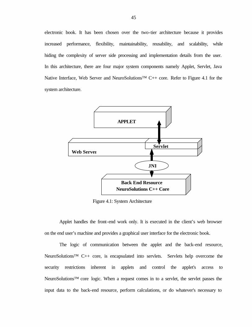
45
electronic book. It has been chosen over the two-tier architecture because it provides
increased performance, flexibility, maintainability, reusability, and scalability, while
hiding the complexity of server side processing and implementation details from the user.
In this architecture, there are four major system components namely Applet, Servlet, Java
Native Interface, Web Server and NeuroSolutions™ C++ core. Refer to Figure 4.1 for the
system architecture.
Figure 4.1: System Architecture
Applet handles the front-end work only. It is executed in the client’s web browser
on the end user’s machine and provides a graphical user interface for the electronic book.
The logic of communication between the applet and the back-end resource,
NeuroSolutions™ C++ core, is encapsulated into servlets. Servlets help overcome the
security restrictions inherent in applets and control the applet's access to
NeuroSolutions™ core logic. When a request comes in to a servlet, the servlet passes the
input data to the back-end resource, perform calculations, or do whatever's necessary to
APPLET
Servlet Web Server
Back End Resource NeuroSolutions C++ Core
JNI
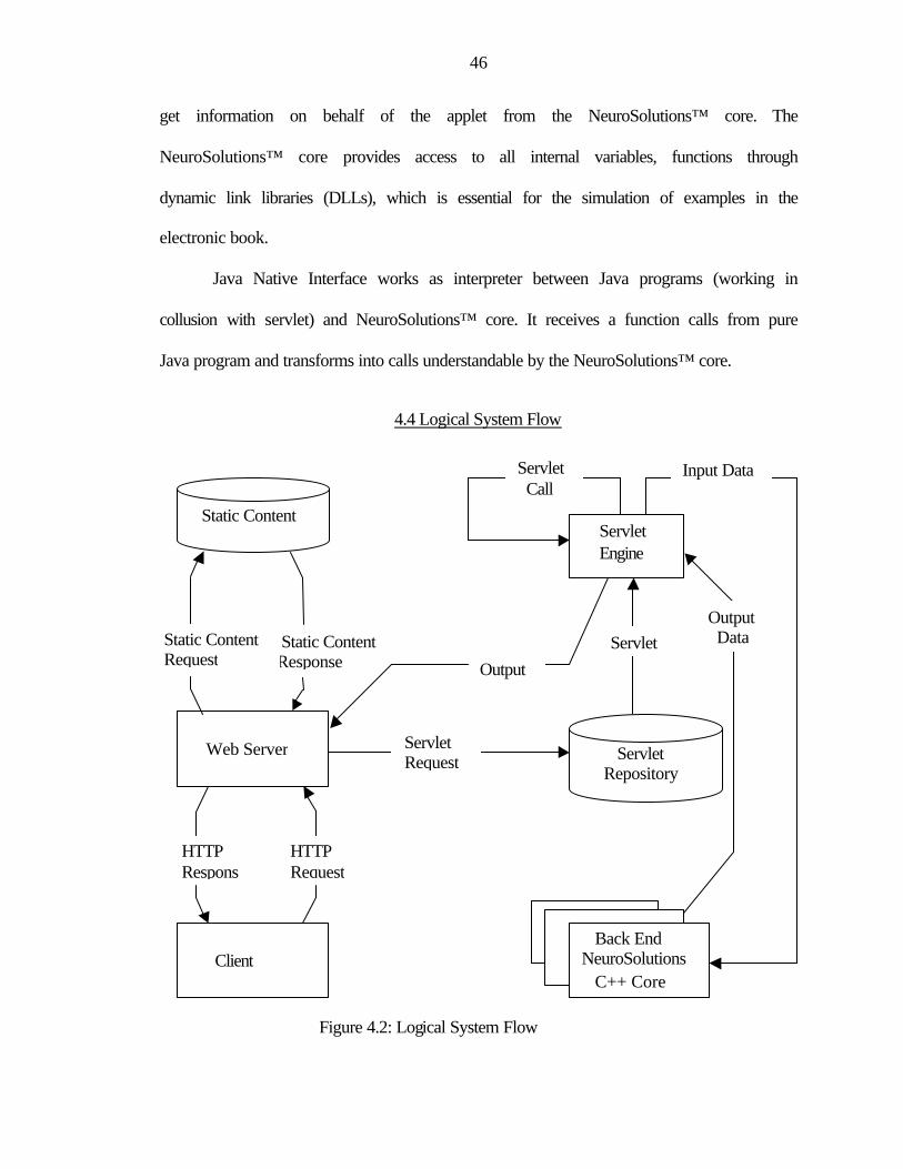
46
get information on behalf of the applet from the NeuroSolutions™ core. The
NeuroSolutions™ core provides access to all internal variables, functions through
dynamic link libraries (DLLs), which is essential for the simulation of examples in the
electronic book.
Java Native Interface works as interpreter between Java programs (working in
collusion with servlet) and NeuroSolutions™ core. It receives a function calls from pure
Java program and transforms into calls understandable by the NeuroSolutions™ core.
4.4 Logical System Flow
Figure 4.2: Logical System Flow
Static Content
Web Server
Client
Static Content Response
HTTP Request
Back End NeuroSolutions C++ Core
Servlet Engine
Servlet Repository
Servlet
Servlet Call
Output
Input Data
Servlet Request
Output Data Static Content
Request
HTTP Respons
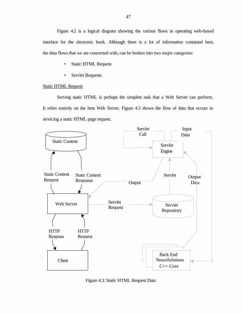
47
Figure 4.2 is a logical diagram showing the various flows in operating web-based
interface for the electronic book. Although there is a lot of information contained here,
the data flows that we are concerned with, can be broken into two major categories:
• Static HTML Request.
• Servlet Requests.
Static HTML Request
Serving static HTML is perhaps the simplest task that a Web Server can perform.
It relies entirely on the host Web Server. Figure 4.3 shows the flow of data that occurs in
servicing a static HTML page request.
Figure 4.3: Static HTML Request Data
Output Data
Static Content
Web Server
Client
Static Content Response
HTTP Request
Back End NeuroSolutions C++ Core
Servlet Engine
Servlet Repository
Servlet
Output
Servlet Call
Input Data
Servlet Request
Static Content Request
HTTP Respons
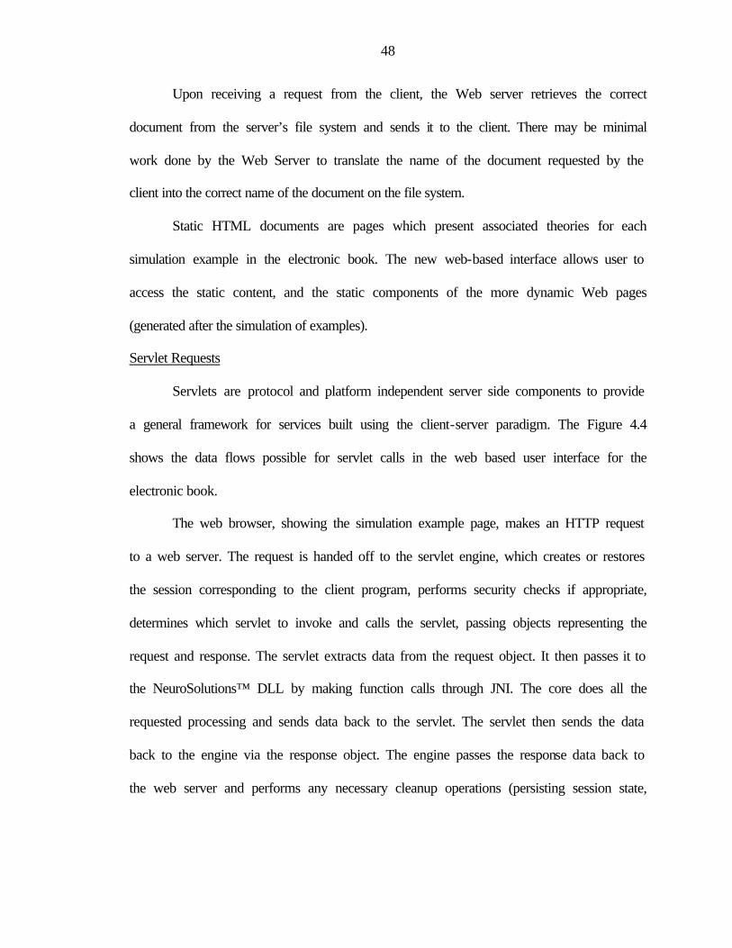
48
Upon receiving a request from the client, the Web server retrieves the correct
document from the server’s file system and sends it to the client. There may be minimal
work done by the Web Server to translate the name of the document requested by the
client into the correct name of the document on the file system.
Static HTML documents are pages which present associated theories for each
simulation example in the electronic book. The new web-based interface allows user to
access the static content, and the static components of the more dynamic Web pages
(generated after the simulation of examples).
Servlet Requests
Servlets are protocol and platform independent server side components to provide
a general framework for services built using the client-server paradigm. The Figure 4.4
shows the data flows possible for servlet calls in the web based user interface for the
electronic book.
The web browser, showing the simulation example page, makes an HTTP request
to a web server. The request is handed off to the servlet engine, which creates or restores
the session corresponding to the client program, performs security checks if appropriate,
determines which servlet to invoke and calls the servlet, passing objects representing the
request and response. The servlet extracts data from the request object. It then passes it to
the NeuroSolutions™ DLL by making function calls through JNI. The core does all the
requested processing and sends data back to the servlet. The servlet then sends the data
back to the engine via the response object. The engine passes the response data back to
the web server and performs any necessary cleanup operations (persisting session state,
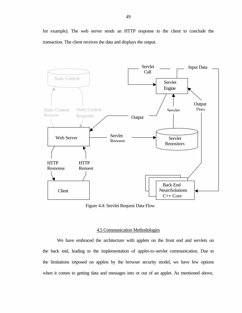
49
for example). The web server sends an HTTP response to the client to conclude the
transaction. The client receives the data and displays the output.
Figure 4.4: Servlet Request Data Flow
4.5 Communication Methodologies
We have embraced the architecture with applets on the front end and servlets on
the back end, leading to the implementation of applet-to-servlet communication. Due to
the limitations imposed on applets by the browser security model, we have few options
when it comes to getting data and messages into or out of an applet. As mentioned above,
Static Content
Web Server
Client
HTTP Response
Static Content Response
HTTP Request
Back End NeuroSolutions C++ Core
Servlet Engine
Servlet Repository
Servlet
Servlet Call
Output
Input Data
Servlet Request
Output Data Static Content
Request
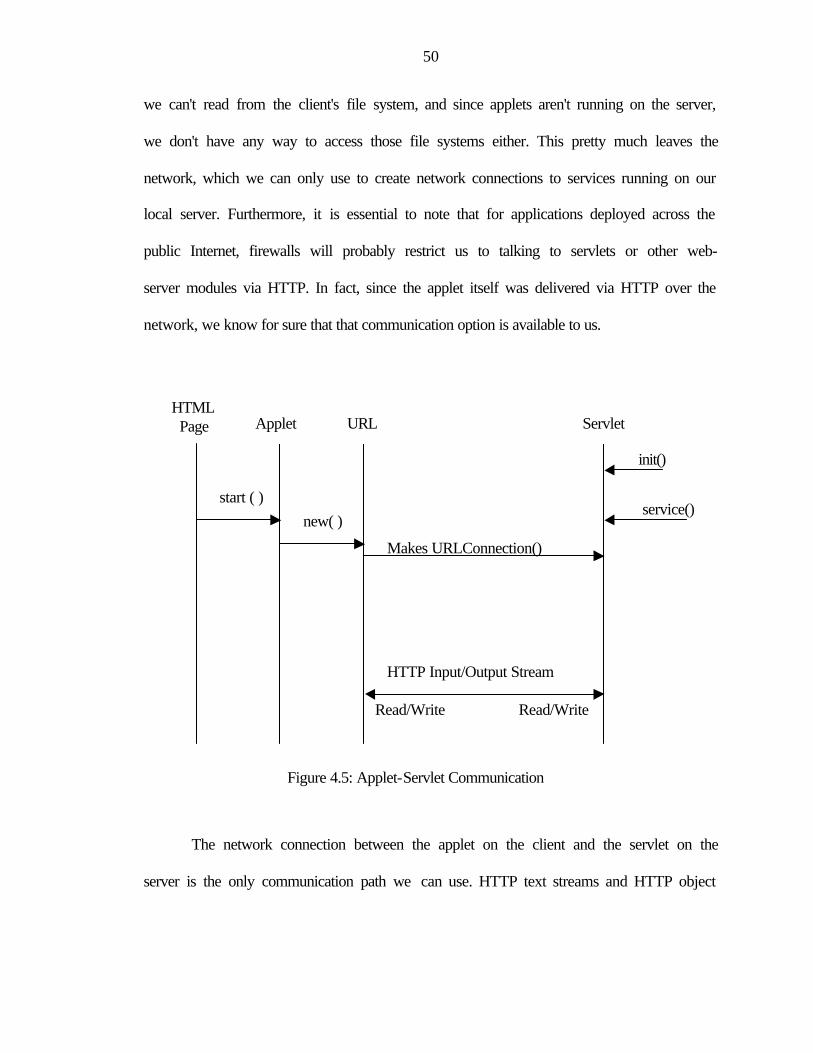
50
we can't read from the client's file system, and since applets aren't running on the server,
we don't have any way to access those file systems either. This pretty much leaves the
network, which we can only use to create network connections to services running on our
local server. Furthermore, it is essential to note that for applications deployed across the
public Internet, firewalls will probably restrict us to talking to servlets or other web-
server modules via HTTP. In fact, since the applet itself was delivered via HTTP over the
network, we know for sure that that communication option is available to us.
Figure 4.5: Applet-Servlet Communication
The network connection between the applet on the client and the servlet on the
server is the only communication path we can use. HTTP text streams and HTTP object
HTTP Input/Output Stream
Read/Write Read/Write
Makes URLConnection()
service()
init()
new( ) start ( )
HTML Page Applet URL Servlet
51
streams are two popular tactics to exchange data between applets and servlets. Refer to
Figure 4.5 for the applet-servlet communication flow.
HTTP text streams are relatively straightforward and easy to use. The applet
establishes a connection to a servlet back on its originating server using Java's URL and
URLConnection classes, reads the information, and interprets them appropriately. In this
mode of communication InputStream is wrapped into a DataInputStream. Using simple
text streams to exchange data has one major weakness, however - the need for the applet
to not only know the format of the data but also perform parsing and conversion of the
data into a useful form.
HTTP object stream is an easier way of exchanging complex data. HTTP
connection can be used to transfer binary data as well as textual data. We can combine
this capability with something called object serialization to pass complete Java objects
from a servlet to an applet. Object serialization provides a program the ability to read or
write a whole object to and from a raw byte stream. It allows Java objects and primitives
to be encoded into a byte stream suitable for streaming to some type of network or to a
file-system, or more generally, to a transmission medium or storage facility. Complex
data can be passed very easily this way with no need for parsing and interpretation.
Object serialization allows us to "flatten" objects into streams of binary data that can go
anywhere an OutputStream can go - to disk, to the screen, or, as in our example, across
an HTTP connection to an applet. HTTP object stream in very much the same way as we
use an HTTP text stream. We initiate a URL connection back to a servlet on our local
web server, and then read in the resulting data. Rather than wrapping the InputStream in a
DataInputStream as before, however, we wrap it in an ObjectInputStream - a special type
52
of stream that reads objects. We then read in each object, casting it to the appropriate
type.
As we can see, object streams give us a very convenient way to exchange
complex collections of information between the applet and the server. Also note that
rather than working with pure data, we're using a more object-oriented approach - even
reusing our objects between the client and the server. This lets us build intelligence into
the objects and avoid duplicating that logic in both client and server portions of our
application.
The above capabilities and strength of HTTP object streams over HTTP text
streams lead us to use HTTP object streams. In our implementation, we required
exchange of complex data in form of arrays, hash tables. These objects were supported
only by HTTP object streams and thus became our choice for implementation.
4.6 Graphical User Interface
The graphical user interface for the interactive book has been developed using
Java APIs. The Java Programming language provides several alternatives for creating
graphical user interface. The most commonly used APIs are Java Foundation Classes
(JFC) and Java Abstract Window Toolkit (AWT). The JFC contains Swing components,
which provide a choice of look and feel. For example, the same program can use either
the Java look and feel or the Windows look and feel or the CDE/Motif look and feel [12].
By contrast, AWT components always have the look and feel of the native platform. So
the user interface is bound to the native platform and will produce different look and feel
on different platforms. Another interesting feature of Swing is that it’s components with
state information, use models to keep the state. Models are set up automatically, so one
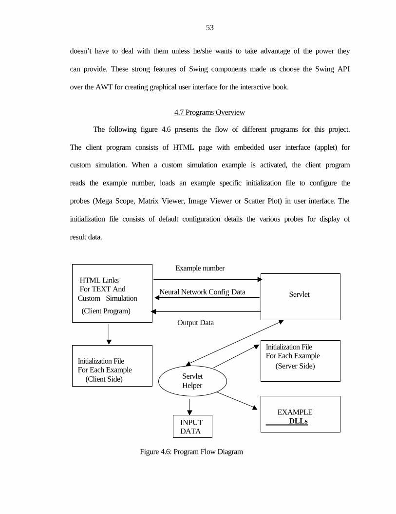
53
doesn’t have to deal with them unless he/she wants to take advantage of the power they
can provide. These strong features of Swing components made us choose the Swing API
over the AWT for creating graphical user interface for the interactive book.
4.7 Programs Overview
The following figure 4.6 presents the flow of different programs for this project.
The client program consists of HTML page with embedded user interface (applet) for
custom simulation. When a custom simulation example is activated, the client program
reads the example number, loads an example specific initialization file to configure the
probes (Mega Scope, Matrix Viewer, Image Viewer or Scatter Plot) in user interface. The
initialization file consists of default configuration details the various probes for display of
result data.
Figure 4.6: Program Flow Diagram
Neural Network Config Data
Output Data
Example number HTML Links For TEXT And Custom Simulation
(Client Program)
Servlet
Servlet Helper
Initialization File For Each Example (Server Side)
EXAMPLE DLLs
Initialization File For Each Example (Client Side)
INPUT DATA
54
The client program also sends the specific example number to the servlet, which
loads the example specific initialization file in the server side. The initialization file has
specific information about the configuration of neural network on the client side. Servlet
makes a call to specific dynamic link library and returns the network configuration data
to the client. These configuration data are displayed within an inspector window. When
the client runs the simulation, it again sends the request along with configured neural
network data to servlet. Servlet makes call to the example specific DLL, pass the
configured neural network data to it.
The DLL sets different neural network parameters on the server side with the
client configured data and processes the request and returns the result to servlet. The
servlet then returns the output data to the client, which is displayed using different probes
in the client browser. The client side program also provides default configuration data for
probes. These configuration data for probes can also be changed as per user request for
better visualization of the result data.
4.8 Implementation Process
The following Figure 4.7 presents step-by-step implementations of web-enabled
interface. These steps have been developed during the implementation of this thesis and
provide a framework for future implementation. It gives a way to utilize the existing C++
programs with minimal modification for the purpose of building web based graphical
interface. The whole implementation process consists of nine major steps as discussed
below:
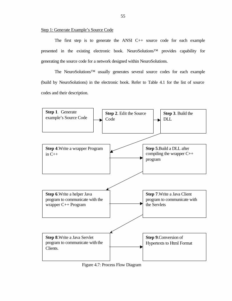
55
Step 1: Generate Example’s Source Code
The first step is to generate the ANSI C++ source code for each example
presented in the existing electronic book. NeuroSolutions™ provides capability for
generating the source code for a network designed within NeuroSolutions.
The NeuroSolutions™ usually generates several source codes for each example
(build by NeuroSolutions) in the electronic book. Refer to Table 4.1 for the list of source
codes and their description.
Figure 4.7: Process Flow Diagram
Step 2. Edit the Source Code
Step 4.Write a wrapper Program in C++
Step 3. Build the DLL
Step 6.Write a helper Java program to communicate with the wrapper C++ Program
Step 7.Write a Java Client program to communicate with the Servlets
Step 5.Build a DLL after compiling the wrapper C++ program
Step 8.Write a Java Servlet program to communicate with the Clients.
Step 9.Conversion of Hypertexts to Html Format
Step 1. Generate example’s Source Code
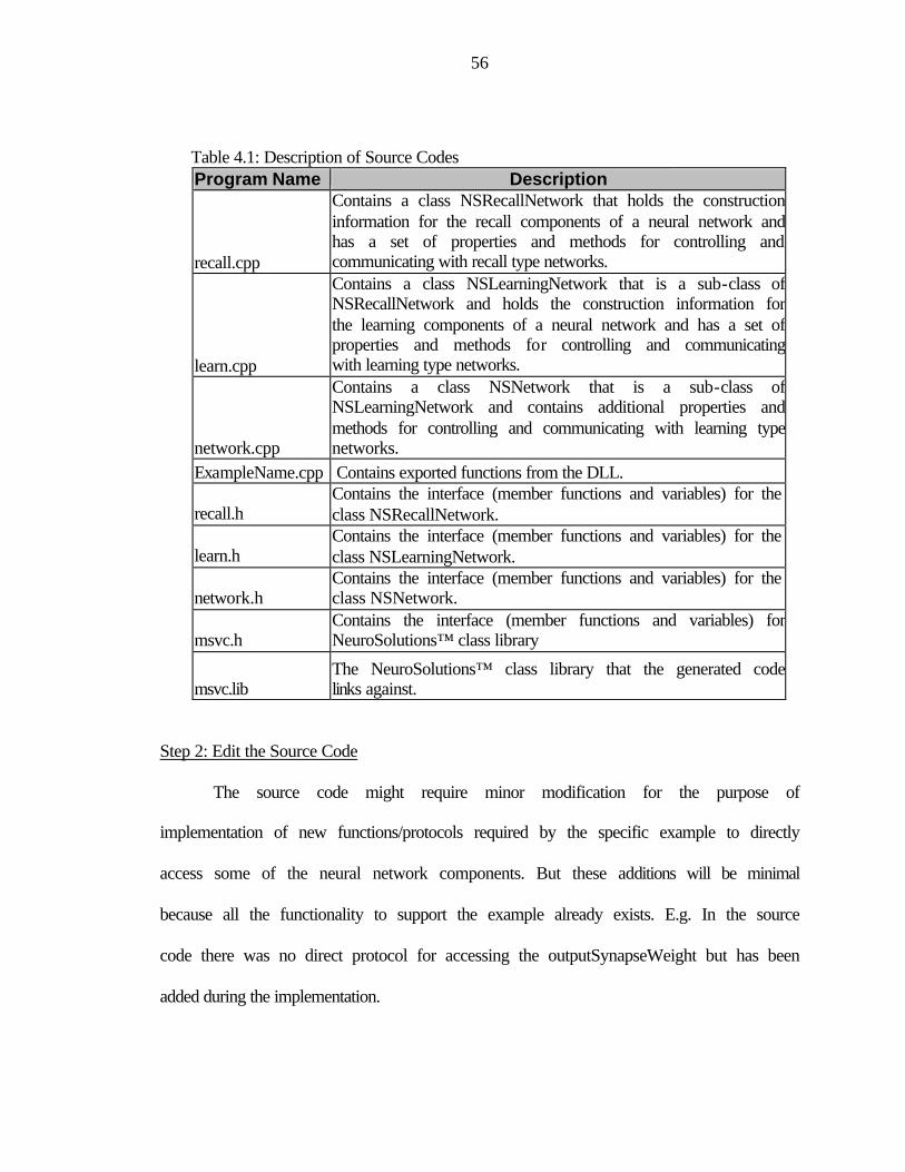
56
Table 4.1: Description of Source Codes Program Name Description
recall.cpp
Contains a class NSRecallNetwork that holds the construction information for the recall components of a neural network and has a set of properties and methods for controlling andcommunicating with recall type networks.
learn.cpp
Contains a class NSLearningNetwork that is a sub-class of NSRecallNetwork and holds the construction information for the learning components of a neural network and has a set of properties and methods for controlling and communicating with learning type networks.
network.cpp
Contains a class NSNetwork that is a sub-class of NSLearningNetwork and contains additional properties and methods for controlling and communicating with learning type networks.
ExampleName.cpp Contains exported functions from the DLL.
recall.h Contains the interface (member functions and variables) for the class NSRecallNetwork.
learn.h Contains the interface (member functions and variables) for the class NSLearningNetwork.
network.h Contains the interface (member functions and variables) for the class NSNetwork.
msvc.h Contains the interface (member functions and variables) for NeuroSolutions™ class library
msvc.lib The NeuroSolutions™ class library that the generated code links against.
Step 2: Edit the Source Code
The source code might require minor modification for the purpose of
implementation of new functions/protocols required by the specific example to directly
access some of the neural network components. But these additions will be minimal
because all the functionality to support the example already exists. E.g. In the source
code there was no direct protocol for accessing the outputSynapseWeight but has been
added during the implementation.

57
int NSLearningNetwork::getoutputSynapseWeight(int epoch) { int rowsize =0; int colsize=0 ; rowsize= outputSynapse->U(); colsize= outputSynapse->V(); for(int i=0; i<colsize; i++) theoutputSynapseWeights[epoch*colsize+i] = outputSynapse->w(i); return 0; }
Step 3: Build the DLL
Compile all the source code (after generation and edition) into a DLL. This needs
to be done with the source code of all the individual examples.
Step 4: Write a Wrapper Program in C++
A wrapper program has to be written which will provide a communication
interface between Java and the C++ program associated with all the examples. This new
wrapper program loads the DLL created in the step 4 and provides the required function
calls supported by the DLL. This will be a generic program and will support all the
examples. It needs to written once for all the individual examples with addition of new
unsupported functions calls. E.g. A small template of the wrapper C++ code, which
creates a new network based on the network type, has been presented below:
include<jni.h> void *aNN;
JNIEXPORT void JNICALL Java_ServerHelper_createNetwork(JNIEnv *env, jobject obj, jint networktype) { int (*pfCreateNet) (void *&, int, char *);

58
pfCreateNet = (int (*) (void *&, int, char *))GetProcAddress(hm, (LPCTSTR)"createNetwork");
if(pfCreateNet!=NULL) { pfCreateNet(aNN, networktype, "123456"); } }
Step 5: Build the DLL
Compile the wrapper C++ program generated in the previous step into a DLL.
This needs to be written once for all the individual examples with addition of new
unsupported functions calls.
Step 6: Write a Helper Java Program to Communicate with the Wrapper C++ Program
A helper Java program needs to be developed to communicate with the wrapper
C++ program. The purpose of this program is to provide the clients (written in pure Java)
with the capabilities to interact with the examples C++ core. This program will be sitting
on the server side to cater the client’s specific requests. It needs to written once for all the
individual examples with addition of new unsupported functions calls in the similar
manner as in step 5. A prototype code has been provided below.
public class ServerHelper { /* Declaration of createNetwork(int networktype) as native C++ method */ private native void createNetwork(int networktype); ServerHelper(String exampleno) { /*Loads the DLL created in Step 5*/
System.loadLibrary(Dllname);
/* Calls createNetwork(networktype) of NeuroSolutions C++ core via wrapper code in Step 4. */
this.createNetwork(networktype); } }

59
Step 7: Write a Java Servlet Program to Communicate with the Clients
A Java Servlet program has to be developed to accomplish the following
activities:
• Listen to client requests for simulation of specific examples
• Contact the helper Java program discussed in step 6 and passes the client’s
specific request for processing.
• Return the result of the specific request to the corresponding clients
Step 8: Write a Java Client Program to Communicate with the Servlets
A client program in pure Java needs to be developed. The client will present the
users with the graphical user interface for the simulation of each example. The graphical
interface is in the form of HTML file with an embedded applet. Java applets enable the
examples to run within a web page. The client program will read an initialization file and
will initialize the specific components such as image, inspectors, plots etc. in the applet
context for each individual example.
Java Foundation Classes (JFC) has been used to create the different GUI
components within the applets environment.
Step 9: Conversion of Hypertexts to Html Format
The last step is to convert hypertexts of the existing electronic book into the html
format. There is plethora of tools (HTML Transit, Web Publisher Pro, Cyberleaf 2.0)
available for this transition, which can convert the texts of the book into the HTML
format. Netscape Composer has been used to build text portion of the electronic book
into the HTML format.

60
4.9 Summary
This chapter provided design and architecture for the general framework
developed for the web-based interface for the interactive electronic book. The step-by-
step system implementation process and sample code discussed in the chapters gives a
way for further enhancement and improvement of the development framework.
61
CHAPTER 5 RESULTS
The web-enabled interface for the interactive book on neural and adaptive
systems has been implemented and tested for its usability and performance over the
Internet on multiple platforms such as Windows, Linux and Sun’s Solaris in the
Computational NeuroEngineering Laboratory at University of Florida. This chapter
presents performance analysis results of the web-enabled interface in comparison with
the present version of the electronic book. It also presents the performance analysis of
web-enabled interface over the web with 56K modem and T1 link. Screen shots and brief
navigation of prototype web-enabled interface for the electronic book have been
presented.
Performance Analysis
The simulation time comparison between web-enabled interface and existing
electronic book are shown in Table 5.1 and Table 5.2. Table 5.1 presents the simulation
time comparison for the example “Batch versus On-Line Adaptation” and Table 5.2
shows simulation time comparison for the example “Function Approximation with the
MLP”.
Simulation time for the interactive examples of the electronic book was recorded
from simulation progress monitoring window provided in the book. Simulation time for
the interactive examples for the web-enabled interface was recorded by time stamping

62
before and after the simulation. The performance evaluation was performed on a PC with
Celeron processor (366 MHz), 96 MB of RAM, 128 K Cache SRAM.
Table 5.1: Simulation Performance Comparison for the Example
“Batch versus On-Line Adaptation” for 200 iterations Serial # Simulation Time in the
existing electronic book (In seconds)
Simulation Time in the web-enabled interface (In seconds)
1 1.00 16.30 2 1.00 16.00 3 1.00 15.54 4 1.00 15.16 5 1.00 15.00
Table 5.2: Simulation Performance Comparison for the Example “Function Approximation with the MLP” for 1000 iterations
Serial # Simulation Time in the existing electronic book (In seconds)
Simulation Time in the web-enabled interface (In seconds)
1 1.00 15.99 2 2.00 16.24 3 1.00 15.21 4 2.00 15.27 5 2.00 15.80
The above table shows that there is a significant difference of simulation time
between the existing electronic book and web-enabled interface. The higher simulation
time in the web-enabled interface is due to JNI overhead for communicating with
NeuroSolutions™ C++ core. The other reason is sleep time introduced between
iterations. The sleep time is required for displaying data in probes for different iterations
otherwise display is very poor. This value can be customized. In reality the simulation
time is of the range 5 – 7 seconds. Higher simulation time for the web-enabled interface
is in fact better because simulation results during iterations can be viewed easily

63
compared to the existing electronic book, where simulation is so fast that viewing
intermediate results is almost impossible.
A performance evaluation of the web-enabled interface for the electronic book
was also performed on 56K modem and T1 link. The performance evaluation was done in
two modes. In the first mode, loading (initialization) time for the web-enabled interface
was analyzed and in the second mode, simulation time for the web-enabled interface was
analyzed. The performance evaluation over T1 link was done on a machine with Pentium
II processor (400 MHz), 128 MB of RAM, 512 K Cache SRAM while the performance
evaluation over 56K Modem was done on from a home machine with Pentium MMX
processor (200MHz), 48 MB of RAM. Although the load and simulation time over the
Internet varies depending upon network speed, network traffic/load and availability of
dynamic bandwidth and client machine configuration, the purpose of this evaluation is to
provide users and programmers, an idea of load and simulation time for the interactive
examples over the Internet.
Table 5.3 shows the loading time of web-enabled interface of two examples over
a T1 link while Table 5.4 shows the loading time of web-enabled interface of two
examples over a 56K modem.
Table 5.3: Performance Evaluation for Load Time on T1 Link Serial # Load Time for the example “Batch
versus On-Line Adaptation” (In Seconds)
Load Time for the example “Function Approximation with the MLP” (In Seconds)
1 4.46 4.40 2 4.37 4.32 3 4.37 4.37 4 4.47 4.36 5 4.42 4.34
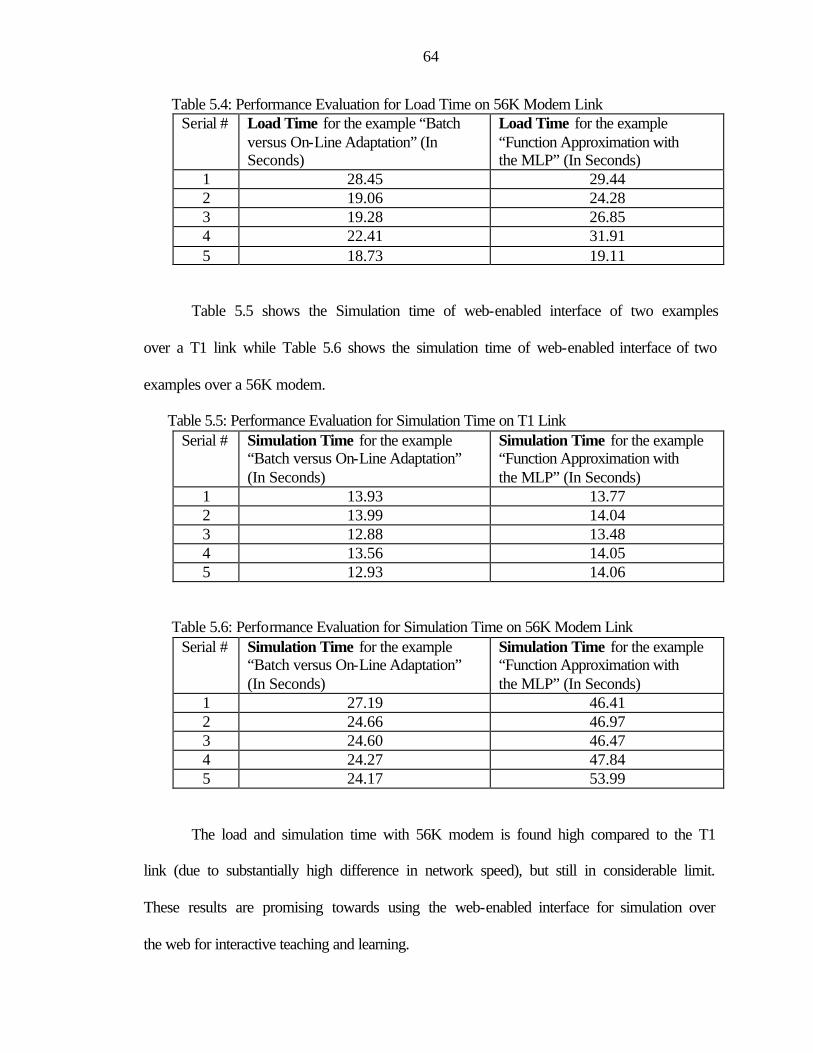
64
Table 5.4: Performance Evaluation for Load Time on 56K Modem Link Serial # Load Time for the example “Batch
versus On-Line Adaptation” (In Seconds)
Load Time for the example “Function Approximation with the MLP” (In Seconds)
1 28.45 29.44 2 19.06 24.28 3 19.28 26.85 4 22.41 31.91 5 18.73 19.11
Table 5.5 shows the Simulation time of web-enabled interface of two examples
over a T1 link while Table 5.6 shows the simulation time of web-enabled interface of two
examples over a 56K modem.
Table 5.5: Performance Evaluation for Simulation Time on T1 Link Serial # Simulation Time for the example
“Batch versus On-Line Adaptation” (In Seconds)
Simulation Time for the example “Function Approximation with the MLP” (In Seconds)
1 13.93 13.77 2 13.99 14.04 3 12.88 13.48 4 13.56 14.05 5 12.93 14.06
Table 5.6: Performance Evaluation for Simulation Time on 56K Modem Link Serial # Simulation Time for the example
“Batch versus On-Line Adaptation” (In Seconds)
Simulation Time for the example “Function Approximation with the MLP” (In Seconds)
1 27.19 46.41 2 24.66 46.97 3 24.60 46.47 4 24.27 47.84 5 24.17 53.99
The load and simulation time with 56K modem is found high compared to the T1
link (due to substantially high difference in network speed), but still in considerable limit.
These results are promising towards using the web-enabled interface for simulation over
the web for interactive teaching and learning.
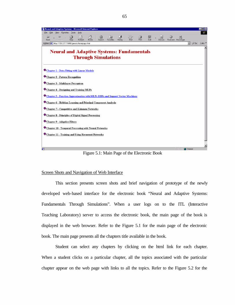
65
Figure 5.1: Main Page of the Electronic Book
Screen Shots and Navigation of Web Interface
This section presents screen shots and brief navigation of prototype of the newly
developed web-based interface for the electronic book “Neural and Adaptive Systems:
Fundamentals Through Simulations”. When a user logs on to the ITL (Interactive
Teaching Laboratory) server to access the electronic book, the main page of the book is
displayed in the web browser. Refer to the Figure 5.1 for the main page of the electronic
book. The main page presents all the chapters title available in the book.
Student can select any chapters by clicking on the html link for each chapter.
When a student clicks on a particular chapter, all the topics associated with the particular
chapter appear on the web page with links to all the topics. Refer to the Figure 5.2 for the
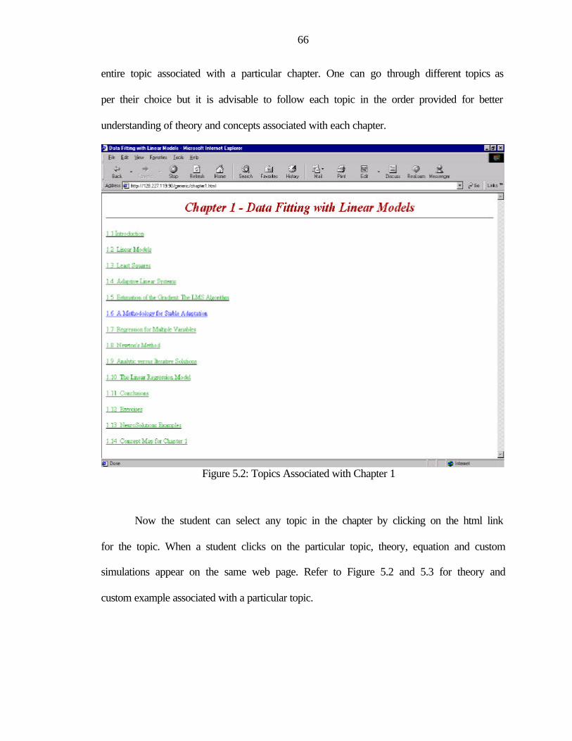
66
entire topic associated with a particular chapter. One can go through different topics as
per their choice but it is advisable to follow each topic in the order provided for better
understanding of theory and concepts associated with each chapter.
Figure 5.2: Topics Associated with Chapter 1
Now the student can select any topic in the chapter by clicking on the html link
for the topic. When a student clicks on the particular topic, theory, equation and custom
simulations appear on the same web page. Refer to Figure 5.2 and 5.3 for theory and
custom example associated with a particular topic.
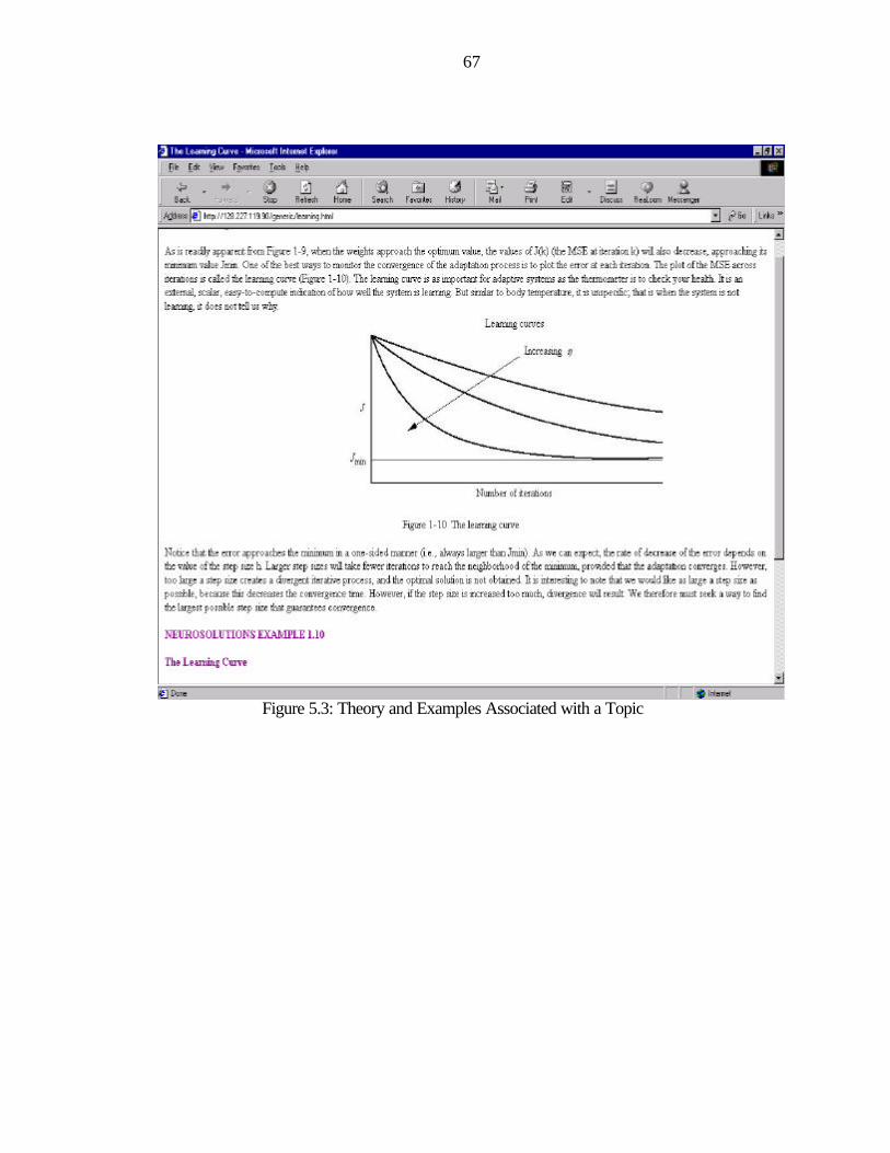
67
Figure 5.3: Theory and Examples Associated with a Topic
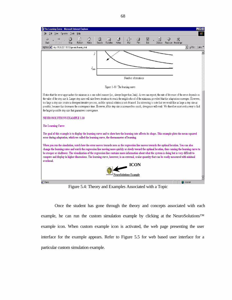
68
Figure 5.4: Theory and Examples Associated with a Topic
Once the student has gone through the theory and concepts associated with each
example, he can run the custom simulation example by clicking at the NeuroSolutions™
example icon. When custom example icon is activated, the web page presenting the user
interface for the example appears. Refer to Figure 5.5 for web based user interface for a
particular custom simulation example.
ICON
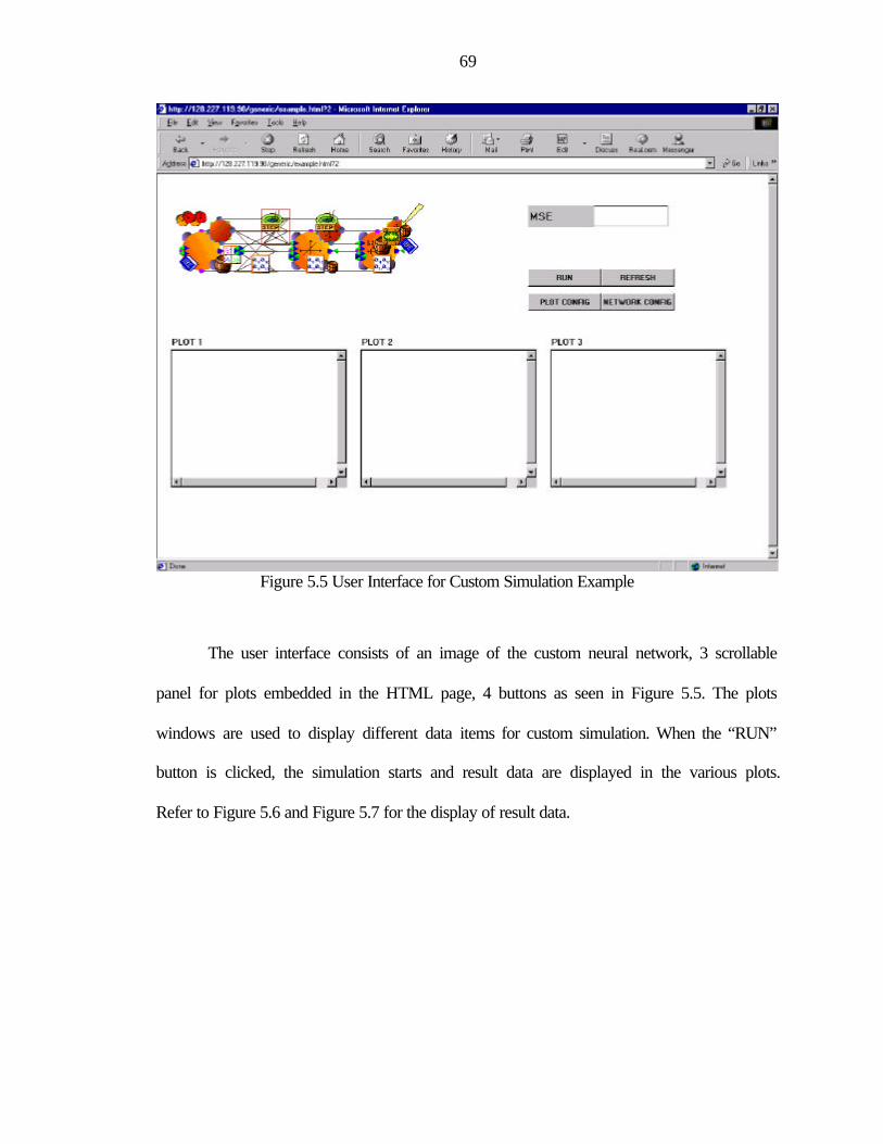
69
Figure 5.5 User Interface for Custom Simulation Example
The user interface consists of an image of the custom neural network, 3 scrollable
panel for plots embedded in the HTML page, 4 buttons as seen in Figure 5.5. The plots
windows are used to display different data items for custom simulation. When the “RUN”
button is clicked, the simulation starts and result data are displayed in the various plots.
Refer to Figure 5.6 and Figure 5.7 for the display of result data.
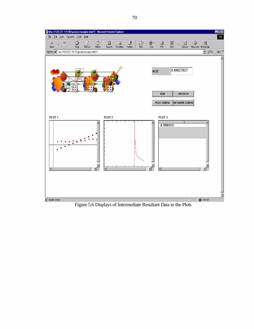
70
Figure 5.6 Displays of Intermediate Resultant Data in the Plots
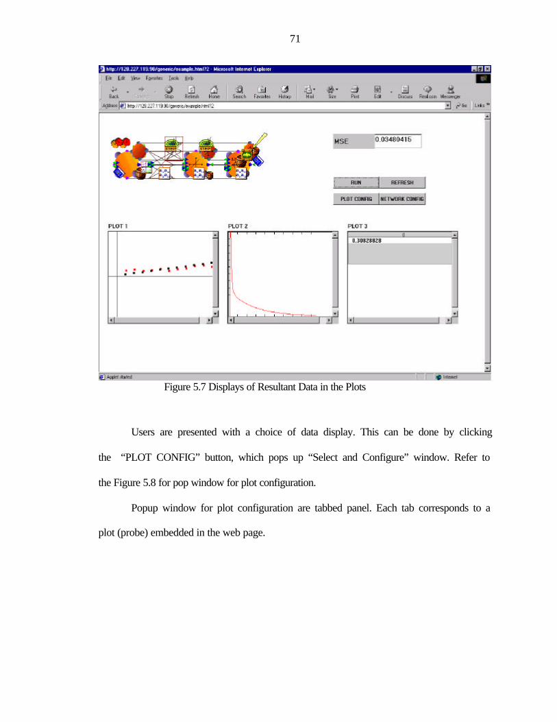
71
Figure 5.7 Displays of Resultant Data in the Plots
Users are presented with a choice of data display. This can be done by clicking
the “PLOT CONFIG” button, which pops up “Select and Configure” window. Refer to
the Figure 5.8 for pop window for plot configuration.
Popup window for plot configuration are tabbed panel. Each tab corresponds to a
plot (probe) embedded in the web page.
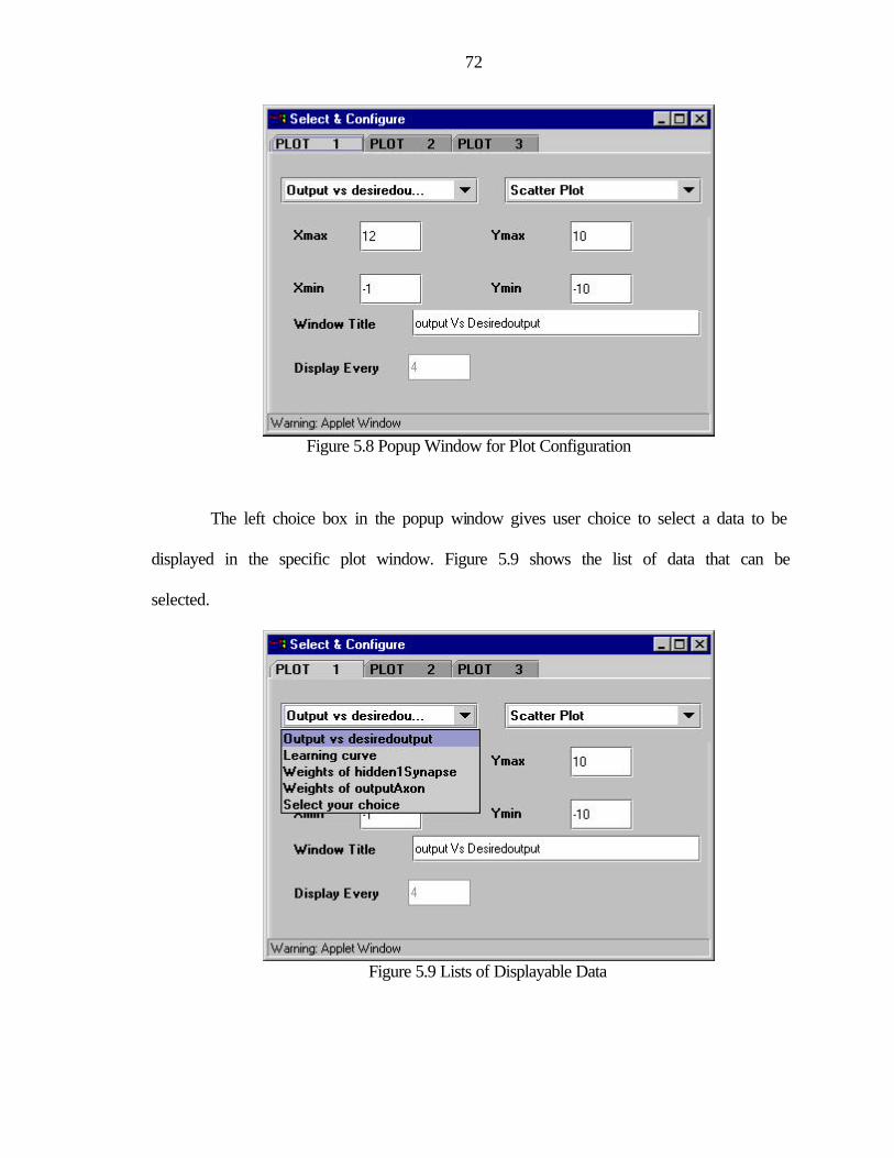
72
Figure 5.8 Popup Window for Plot Configuration
The left choice box in the popup window gives user choice to select a data to be
displayed in the specific plot window. Figure 5.9 shows the list of data that can be
selected.
Figure 5.9 Lists of Displayable Data
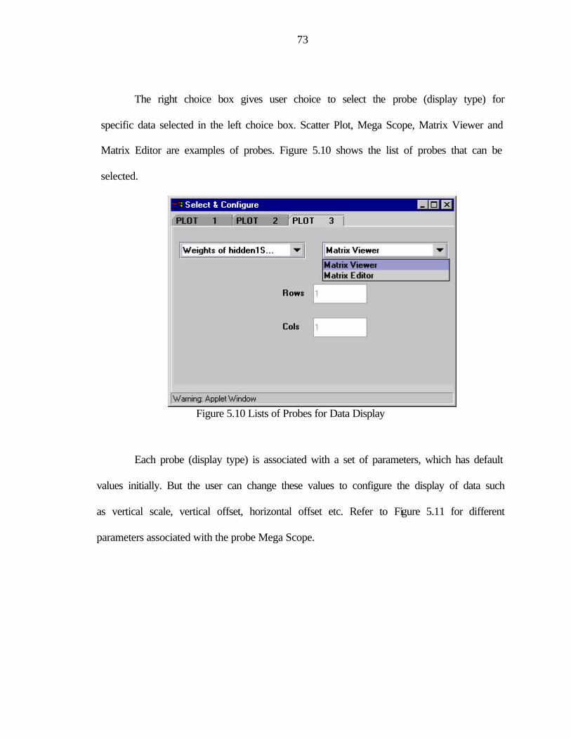
73
The right choice box gives user choice to select the probe (display type) for
specific data selected in the left choice box. Scatter Plot, Mega Scope, Matrix Viewer and
Matrix Editor are examples of probes. Figure 5.10 shows the list of probes that can be
selected.
Figure 5.10 Lists of Probes for Data Display
Each probe (display type) is associated with a set of parameters, which has default
values initially. But the user can change these values to configure the display of data such
as vertical scale, vertical offset, horizontal offset etc. Refer to Figure 5.11 for different
parameters associated with the probe Mega Scope.
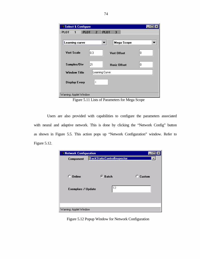
74
Figure 5.11 Lists of Parameters for Mega Scope
Users are also provided with capabilities to configure the parameters associated
with neural and adaptive network. This is done by clicking the “Network Config” button
as shown in Figure 5.5. This action pops up “Network Configuration” window. Refer to
Figure 5.12.
Figure 5.12 Popup Window for Network Configuration
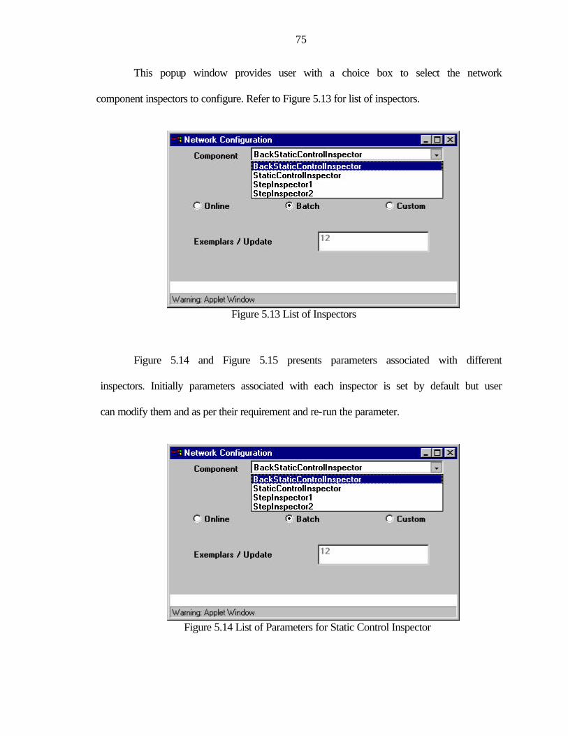
75
This popup window provides user with a choice box to select the network
component inspectors to configure. Refer to Figure 5.13 for list of inspectors.
Figure 5.13 List of Inspectors
Figure 5.14 and Figure 5.15 presents parameters associated with different
inspectors. Initially parameters associated with each inspector is set by default but user
can modify them and as per their requirement and re-run the parameter.
Figure 5.14 List of Parameters for Static Control Inspector
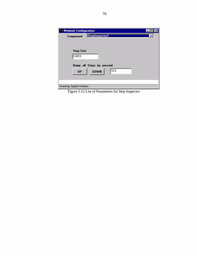
76
Figure 5.15 List of Parameters for Step Inspector
77
CHAPTER 6 CONCLUSION AND SCOPE FOR IMPROVEMENT
An attempt has been made in this thesis to develop design and implementation
framework for interactive, platform independent web based user interface for the
electronic book on neural and adaptive systems.
6.1 Conclusion
The design and implementation of web based graphical user interface for the
interactive book on neural and adaptive systems has been implemented and tested for its
usability and performance over the Internet on multiple platforms such as Windows,
Linux and Sun’s Solaris. It has overcome the limitation of platform independence and
local nature of delivery of the existing version of the electronic book on adaptive and
neural systems.
The web-based graphical user interface built around Java Applets and JFC swing
components has provided a dynamic and friendly user interface to the end user.
Servlet has been used to develop platform independent server side component. In
collusion with web server, servlet engine and Java networking APIs, it has provided a
general framework for communication between the new graphical user interface and
NeuroSolutions™.
The new web-based interface for the electronic book provides students, not only
the theory and concepts in hypertext format, but also a user-friendly environment to run
custom simulations in the area of neural and adaptive systems. It has also the capability to

78
configure the simulation settings. This gives a far greater understandability of the
underlying principles behind the neural and adaptive systems.
This can be used to provide a powerful teaching and learning tool in the area of
neural and adaptive systems and their applications. The general framework developed
during the thesis will also be very useful for the web accessibility of library and
application written in another programming languages (C, C++ etc.).
6.2 Future Work
Although the framework for the web based user interface for electronic is useful,
additional features can be added to make it more flexible and powerful as learning and
teaching tools. Some of the needed features are discussed below:
On-the-fly network-building capability. The custom simulation examples
provided in the book is assumed to be static. The neural network components and
interaction among them is fixed. Network configuration can be changed to a limited
extent. This limits the flexibility of the simulation example. Although building real time
neural network and the interaction among different neural component interactively, is
difficult over the web, additional capability to provide on the fly network building can be
explored to enhance the usefulness and flexibility of the book.
Automation of custom simulation examples. The existing electronic book
provides over 200 custom examples. All the simulations in the interactive book are not
similar and graphical designs also vary from examples to examples. These factors pose a
challenge in generating user interface for each example. A great deal of effort has been
spent to make the framework generic but additional effort is required to use a custom tool

79
or develop a tool for automating the implementation for each custom example in the
interactive book with minimal effort.
Integration of web interface with real-time audio feed. The current page for the
electronic book, displayed on the smart board at the instructor side can be integrated and
synchronized with client’s side graphical display of the page in their browser, so that
whenever a page is scrolled or any note is written on the smart board, same effect should
appear at the student browser. The instructor voice can also be sent along with the
annotations on the smart board using a real-time synchronized audio feed. This will
reduce the bandwidth requirement for participation in the class by remote students and
will make the electronic book more powerful and flexible as learning and teaching tool.
80
LIST OF REFERENCES
1. Jose C. Principe, Neil R. Euliano and W. Curt Lefebvre, “Neural and Adaptive Systems: Fundamental Through Simulations”, John Wiley & Sons, Inc, ISBN 0-471-35167-9, 1999.
2. Jose C. Principe, Neil R. Euliano and W. Curt Lefebvre, “Innovating Adaptive
and Neural Systems Instruction with Interactive Electronic Books”, Proceeding of IEEE, Jan 2000.
3. NeuroDimension Inc., Gainesville, Florida, Product Explanations,
http://www.nd.com/products/nsbook.htm, May 2000. 4. Carnegie Mellon Software Engineering Institute, Software Technology Review,
http://www.sei.cmu.edu/str/descriptions/clientserver_body.html, Jan 2001
5. Randy Chow, Theodore Johnson, “Distributed Operating Systems & Algorithm, Addison-Wesley Pub Co, ISBN 0201498383, March 1997.
6. Sun Microsystems Inc., Palo Alto, California, Java™ SDK, Standard Edition
Documentation, http://java.sun.com/products/jdk/1.2/docs/index.html, April 2000. 7. Sheng Liang, “The Java Native Interface: Programmer’s Guide and Specification
(Java Series)”, Addison-Wesley Pub Co, ISBN 0201325772, June 1999. 8. Sun Microsystems Inc., Palo Alto, California, Specialized Trails,
http://www.java.sun.com/docs/books/tutorial/, April 2000.
9. Sun Microsystems Inc., Palo Alto, California, Specialized Trails, http://developer.java.sun.com/developer/onlineTraining/Servlets/, April 2000.
10. Duane K Fields, “Applet to Servlet Communication for Enterprise Applications”,
http://developer.netscape.com/viewsource/fields_servlet/fields_servlet.html, August 2000.
11. Larry O’Brien, “Applet to Servlet Communication”, http://www.devx.com/ Feb 2000.
12. Kathy Walrath, Mary Campione, “The JFC Swing Tutorial: A guide to constructing GUIs, Addison-Wesley Pub Co, ISBN 0201433214, July 1999.

81
BIOGRAPHICAL SKETCH
Rajesh Kumar was born on October 28, 1973 in Patna, India. He received his
Bachelor of Technology degree in electrical engineering from the Indian Institute of
Technology, Kharagpur, India in May 1996. After his graduation, he worked for Infosys,
Northwestern Mutual, Milwaukee and Microsoft Corporation in Washington state as a
software engineer. He joined the Department of Computer and Information Science and
Engineering at the University of Florida in fall 1999. He worked as a research assistant in
the Computational NeuroEngineering Laboratory. He received his Master of Science
degree in August 2001. His research interests include designing interactive web-based
applications and e-commerce.