waterworks catalog - tyler union...3 mechanical joint fittings | bendsc153 ductile iron compact...
TRANSCRIPT

11910 CR 492 / TYLER, TEXAS 75706 / (800) 527-84781501 WEST 17TH ST / ANNISTON, ALABAMA 36201 / (800) 226-7601
1001 EL CAMINO AVE / CORONA, CALIFORNIA 92879 / (866) 527-8471PORTLAND, OREGON 97203
NEW LENOX, ILLINOIS 60451GRAND PRAIRIE, TEXAS 75050
ANNISTON, ALABAMA 36207ELMER, NEW JERSEY 08318
LITHIA SPRINGS, GEORGIA 30122
Product warranty with terms and conditions of sale located at www.McWane.com.
WATERWORKS CATALOGPC-2019, January 2019www.tylerunion.com
UL®
RE
GISTERED FIR
M
ISO 9001:2015CERTIFIED
10014257
Tyler Union
TABLE OF CONTENTS
ANSI/AWWA C153 Mechanical Joint Fittings …………………………………………………………… 1Bends …………………………………………………………………………………………………………………………………… 2–4Tees ……………………………………………………………………………………………………………………………………… 5–7Wyes ……………………………………………………………………………………………………………………………………… 7Offsets (MJxMJ) or (MJxPE) ……………………………………………………………………………………………………………… 7Solid & Tapped Plugs & Caps ……………………………………………………………………………………………………………… 8Tapping Sleeves …………………………………………………………………………………………………………………………… 8Solid Sleeves ……………………………………………………………………………………………………………………………… 8Reducers …………………………………………………………………………………………………………………………………… 9Adapters ………………………………………………………………………………………………………………………………… 10Glands ………………………………………………………………………………………………………………………………………11Dual Purpose Cutting-In Sleeves ……………………………………………………………………………………………………… 12MJ Hydrant Bury ………………………………………………………………………………………………………………………… 12
ANSI/AWWA C110 Mechanical Joint Fittings ……………………………………………………………… 13Bends ………………………………………………………………………………………………………………………………… 14–15Offsets …………………………………………………………………………………………………………………………………… 15Tees …………………………………………………………………………………………………………………………………… 16–17Reducers ………………………………………………………………………………………………………………………………… 18Solid Sleeves …………………………………………………………………………………………………………………………… 19MJxFE Adapters ………………………………………………………………………………………………………………………… 19Plugs …………………………………………………………………………………………………………………………………… 20Caps ……………………………………………………………………………………………………………………………………… 20Wyes/Laterals …………………………………………………………………………………………………………………………… 21MJ Glands ……………………………………………………………………………………………………………………………… 21
ANSI/AWWA C153 Push-On Joint Fittings …………………………………………………………………22Bends ………………………………………………………………………………………………………………………………… 23–24Tees …………………………………………………………………………………………………………………………………… 25–26Wyes …………………………………………………………………………………………………………………………………… 26Reducers ………………………………………………………………………………………………………………………………… 27Caps and Plugs ………………………………………………………………………………………………………………………… 27Adapters ………………………………………………………………………………………………………………………………… 27UT Hydrant Bury ………………………………………………………………………………………………………………………… 27
ANSI/AWWA C110 Class 125 Flange Fittings ………………………………………………………………28Bends ………………………………………………………………………………………………………………………………… 29–31Tees …………………………………………………………………………………………………………………………………… 31–34Reducers ………………………………………………………………………………………………………………………………… 35Wyes/Laterals …………………………………………………………………………………………………………………………… 36Flange By Flare Pieces ………………………………………………………………………………………………………………… 36Flanges …………………………………………………………………………………………………………………………………… 37Flange Sludge Shoes …………………………………………………………………………………………………………………… 37Adapter Flanges ………………………………………………………………………………………………………………………… 37Tap Locations …………………………………………………………………………………………………………………………… 38
ANSI/AWWA C110 Class 250 Flange Fittings ………………………………………………………………39Bends ………………………………………………………………………………………………………………………………… 40–41Tees ……………………………………………………………………………………………………………………………………… 42Reducers ………………………………………………………………………………………………………………………………… 43Wyes/Laterals …………………………………………………………………………………………………………………………… 44Flange By Flare Pieces ………………………………………………………………………………………………………………… 45
Municipal Castings & Valve and Service Boxes ……………………………………………………………466500 Screw Type Valve Boxes ………………………………………………………………………………………………………… 466850 2 Piece Screw Type Valve Boxes ………………………………………………………………………………………………… 476855 2 Piece Screw Type Valve Boxes ………………………………………………………………………………………………… 486860 3 Piece Screw Type Valve Boxes ……………………………………………………………………………………………… 49–50Valve Box Lids …………………………………………………………………………………………………………………………… 51Valve Box Risers and Specialty Tops …………………………………………………………………………………………………… 52Meter Box Rings and Covers …………………………………………………………………………………………………………… 53
1
MECHANICAL JOINT FITTINGS
SAMPLE SPECIFICATIONS (Current ANSI/AWWA revisions apply)
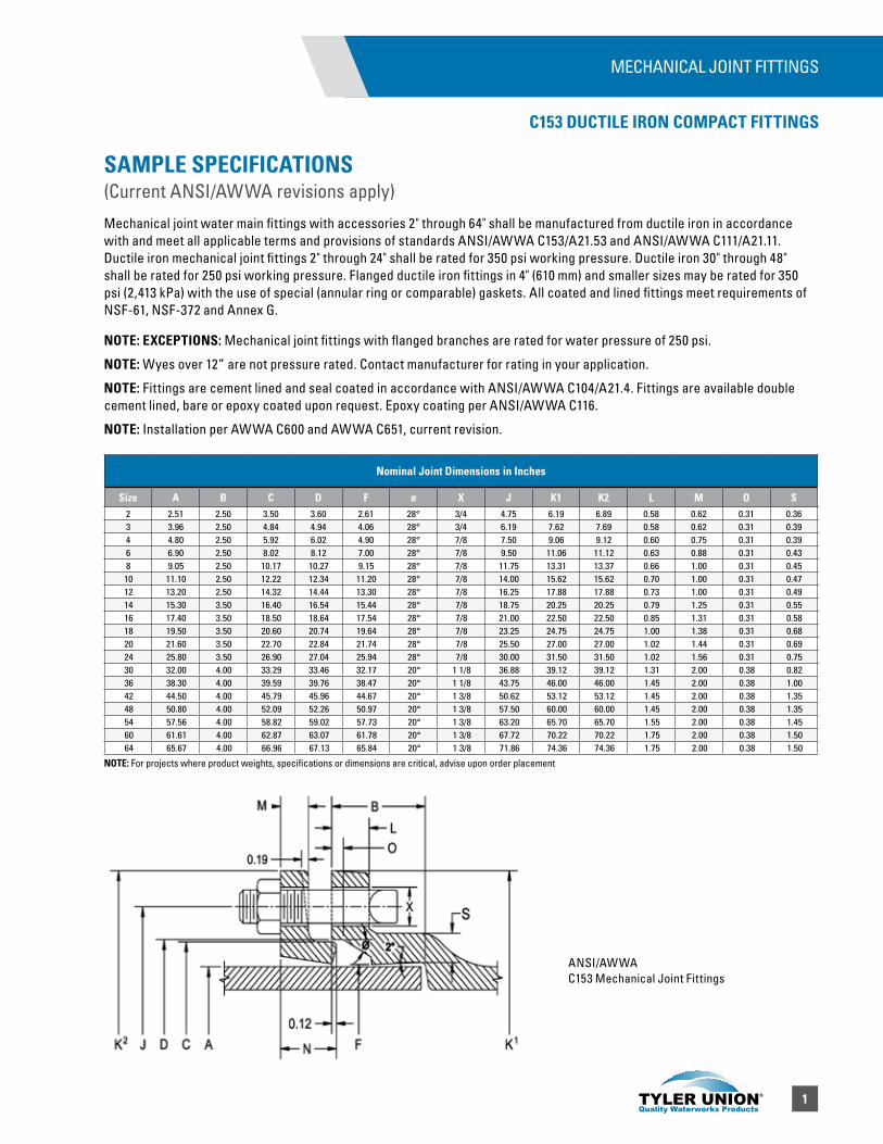
Mechanical joint water main fittings with accessories 2" through 64" shall be manufactured from ductile iron in accordance with and meet all applicable terms and provisions of standards ANSI/AWWA C153/A21.53 and ANSI/AWWA C111/A21.11. Ductile iron mechanical joint fittings 2" through 24" shall be rated for 350 psi working pressure. Ductile iron 30" through 48" shall be rated for 250 psi working pressure. Flanged ductile iron fittings in 4" (610 mm) and smaller sizes may be rated for 350 psi (2,413 kPa) with the use of special (annular ring or comparable) gaskets. All coated and lined fittings meet requirements of NSF-61, NSF-372 and Annex G.
NOTE: EXCEPTIONS: Mechanical joint fittings with flanged branches are rated for water pressure of 250 psi.
NOTE: Wyes over 12” are not pressure rated. Contact manufacturer for rating in your application.
NOTE: Fittings are cement lined and seal coated in accordance with ANSI/AWWA C104/A21.4. Fittings are available double cement lined, bare or epoxy coated upon request. Epoxy coating per ANSI/AWWA C116.
NOTE: Installation per AWWA C600 and AWWA C651, current revision.
C153 DUCTILE IRON COMPACT FITTINGS
ANSI/AWWA C153 Mechanical Joint Fittings
Nominal Joint Dimensions in Inches
Size A B C D F ø X J K1 K2 L M O S2 2.51 2.50 3.50 3.60 2.61 28° 3/4 4.75 6.19 6.89 0.58 0.62 0.31 0.363 3.96 2.50 4.84 4.94 4.06 28° 3/4 6.19 7.62 7.69 0.58 0.62 0.31 0.394 4.80 2.50 5.92 6.02 4.90 28° 7/8 7.50 9.06 9.12 0.60 0.75 0.31 0.396 6.90 2.50 8.02 8.12 7.00 28° 7/8 9.50 11.06 11.12 0.63 0.88 0.31 0.438 9.05 2.50 10.17 10.27 9.15 28° 7/8 11.75 13.31 13.37 0.66 1.00 0.31 0.4510 11.10 2.50 12.22 12.34 11.20 28° 7/8 14.00 15.62 15.62 0.70 1.00 0.31 0.4712 13.20 2.50 14.32 14.44 13.30 28° 7/8 16.25 17.88 17.88 0.73 1.00 0.31 0.4914 15.30 3.50 16.40 16.54 15.44 28° 7/8 18.75 20.25 20.25 0.79 1.25 0.31 0.5516 17.40 3.50 18.50 18.64 17.54 28° 7/8 21.00 22.50 22.50 0.85 1.31 0.31 0.5818 19.50 3.50 20.60 20.74 19.64 28° 7/8 23.25 24.75 24.75 1.00 1.38 0.31 0.6820 21.60 3.50 22.70 22.84 21.74 28° 7/8 25.50 27.00 27.00 1.02 1.44 0.31 0.6924 25.80 3.50 26.90 27.04 25.94 28° 7/8 30.00 31.50 31.50 1.02 1.56 0.31 0.7530 32.00 4.00 33.29 33.46 32.17 20° 1 1/8 36.88 39.12 39.12 1.31 2.00 0.38 0.8236 38.30 4.00 39.59 39.76 38.47 20° 1 1/8 43.75 46.00 46.00 1.45 2.00 0.38 1.0042 44.50 4.00 45.79 45.96 44.67 20° 1 3/8 50.62 53.12 53.12 1.45 2.00 0.38 1.3548 50.80 4.00 52.09 52.26 50.97 20° 1 3/8 57.50 60.00 60.00 1.45 2.00 0.38 1.3554 57.56 4.00 58.82 59.02 57.73 20° 1 3/8 63.20 65.70 65.70 1.55 2.00 0.38 1.4560 61.61 4.00 62.87 63.07 61.78 20° 1 3/8 67.72 70.22 70.22 1.75 2.00 0.38 1.5064 65.67 4.00 66.96 67.13 65.84 20° 1 3/8 71.86 74.36 74.36 1.75 2.00 0.38 1.50
NOTE: For projects where product weights, specifications or dimensions are critical, advise upon order placement
2
A
A
T
R
A
R
A
T
A
A
R
T
A A
R
T
A
AR
T
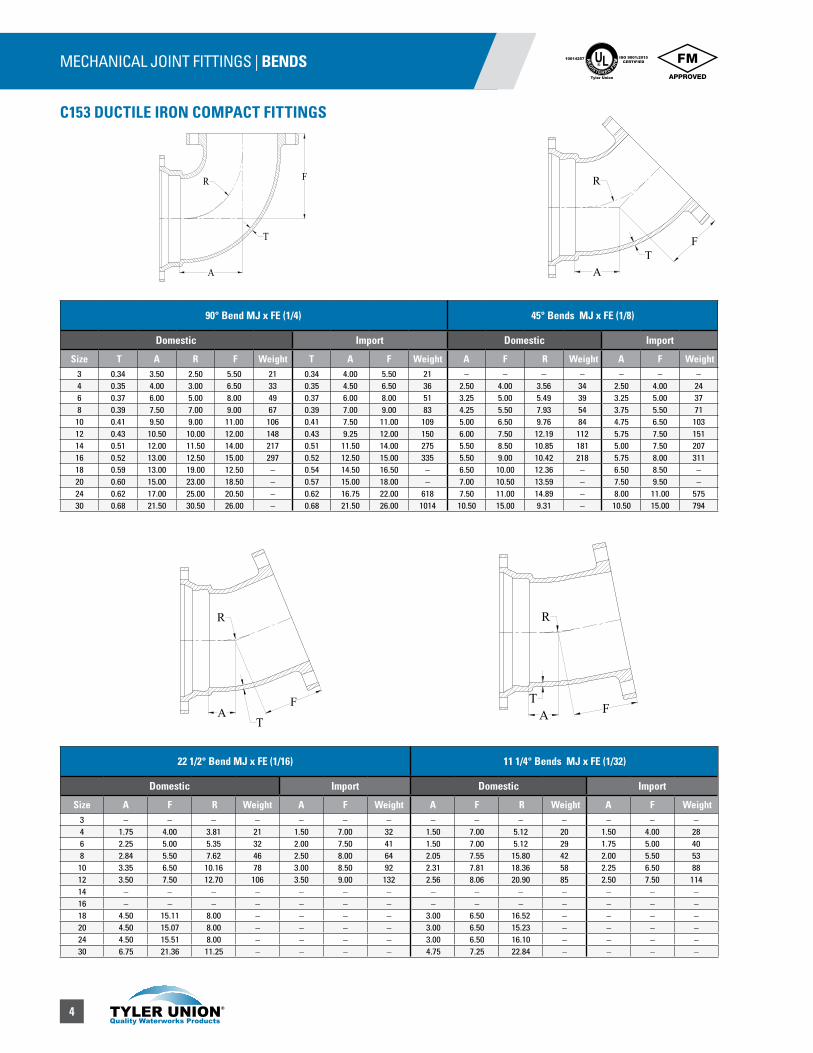
MECHANICAL JOINT FITTINGS | BENDS
C153 DUCTILE IRON COMPACT FITTINGS
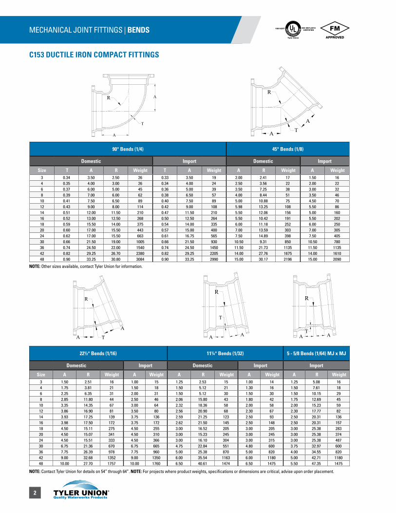
90° Bends (1/4) 45° Bends (1/8)
Domestic Import Domestic Import
Size T A R Weight T A Weight A R Weight A Weight3 0.34 3.50 2.50 26 0.33 3.50 19 2.00 2.41 17 1.50 164 0.35 4.00 3.00 26 0.34 4.00 24 2.50 3.56 22 2.00 226 0.37 6.00 5.00 45 0.36 5.00 39 3.50 7.25 38 3.00 328 0.39 7.00 6.00 62 0.38 6.50 57 4.00 8.44 51 3.50 4610 0.41 7.50 6.50 89 0.40 7.50 89 5.00 10.88 75 4.50 7012 0.43 9.00 8.00 114 0.42 9.00 108 5.98 13.25 108 5.50 8614 0.51 12.00 11.50 210 0.47 11.50 210 5.50 12.06 156 5.00 16016 0.52 13.00 12.50 268 0.50 12.50 264 5.50 10.42 191 5.50 20218 0.59 15.50 14.00 375 0.54 14.00 335 6.00 11.18 252 6.00 25020 0.60 17.00 15.50 443 0.57 15.00 400 7.00 13.59 303 7.00 30524 0.62 17.00 15.50 663 0.61 16.75 565 7.50 14.89 398 7.50 40530 0.66 21.50 19.00 1005 0.66 21.50 930 10.50 9.31 850 10.50 78036 0.74 24.50 22.00 1540 0.74 24.50 1450 11.50 21.73 1135 11.50 113542 0.82 29.25 26.70 2380 0.82 29.25 2205 14.00 27.76 1675 14.00 161048 0.90 33.25 30.80 3084 0.90 33.25 2990 15.00 30.17 2196 15.00 2090
22½° Bends (1/16) 11¼° Bends (1/32) 5 - 5/8 Bends (1/64) MJ x MJ
Domestic Import Domestic Import Import
Size A R Weight A Weight A R Weight A Weight A R Weight3 1.50 2.51 16 1.00 15 1.25 2.53 15 1.00 14 1.25 5.08 164 1.75 3.81 21 1.50 18 1.50 5.12 21 1.30 16 1.50 7.61 186 2.25 6.35 31 2.00 31 1.50 5.12 30 1.50 30 1.50 10.15 298 2.85 11.80 44 2.50 46 2.06 15.80 43 1.80 42 1.75 12.69 45
10 3.35 14.35 67 3.00 64 2.32 18.36 58 2.00 58 2.00 15.23 5912 3.86 16.90 81 3.50 80 2.56 20.90 68 2.30 67 2.30 17.77 8214 3.93 17.25 139 3.75 136 2.59 21.25 123 2.50 93 2.50 20.31 13616 3.98 17.50 172 3.75 172 2.62 21.50 145 2.50 148 2.50 20.31 15718 4.50 15.11 275 4.50 255 3.00 16.52 205 3.00 205 3.00 25.38 28320 4.50 15.07 341 4.50 310 3.00 15.23 245 3.00 245 3.00 25.38 37424 4.50 15.51 333 4.50 366 3.00 16.10 304 3.00 315 3.00 25.38 48730 6.75 21.36 670 6.75 665 4.75 22.84 551 4.80 600 3.75 32.97 60036 7.75 26.39 978 7.75 960 5.00 25.38 870 5.00 820 4.00 34.55 82042 9.00 32.68 1352 9.00 1350 6.00 35.54 1163 6.00 1180 5.00 42.71 118048 10.00 27.70 1757 10.00 1760 6.50 40.61 1474 6.50 1475 5.50 47.35 1475
UL®
RE
GISTERED FIR
M
ISO 9001:2015CERTIFIED
10014257
Tyler Union
NOTE: Other sizes available, contact Tyler Union for information.
NOTE: Contact Tyler Union for details on 54” through 64”. NOTE: For projects where product weights, specifications or dimensions are critical, advise upon order placement.
3
MECHANICAL JOINT FITTINGS | BENDS
C153 DUCTILE IRON COMPACT FITTINGS
UL®
RE
GISTERED FIR
M
ISO 9001:2015CERTIFIED
10014257
Tyler Union
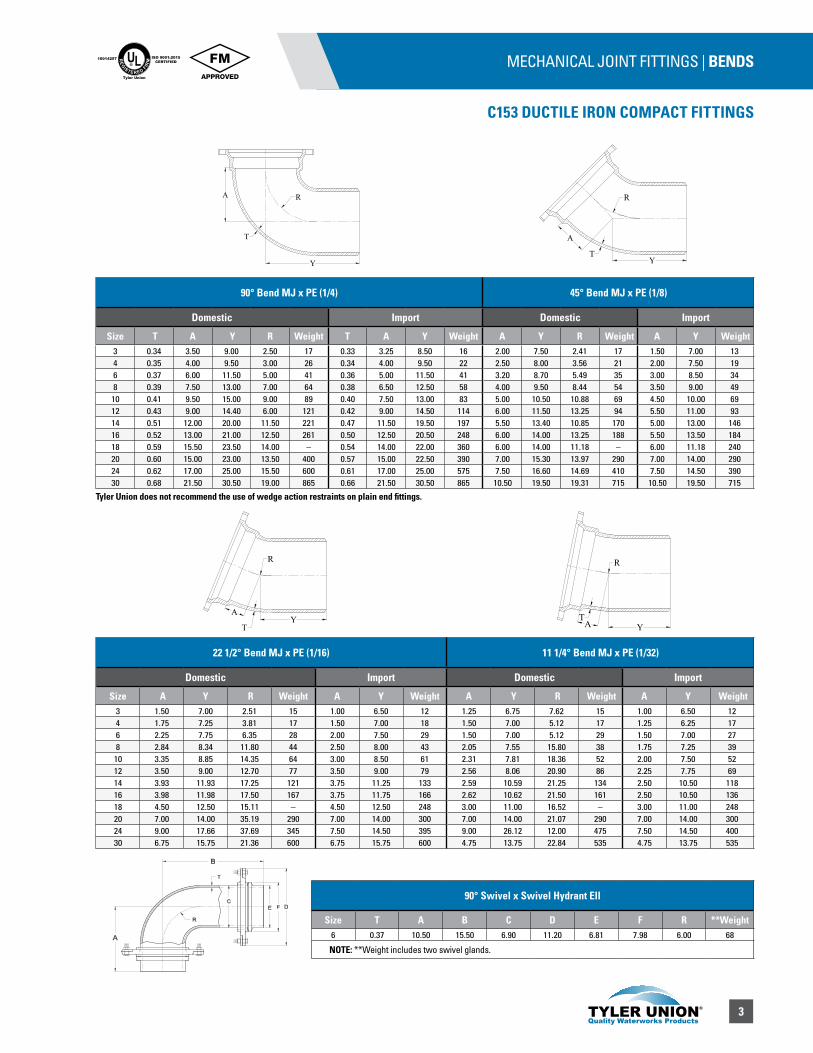
22 1/2° Bend MJ x PE (1/16) 11 1/4° Bend MJ x PE (1/32)
Domestic Import Domestic Import
Size A Y R Weight A Y Weight A Y R Weight A Y Weight3 1.50 7.00 2.51 15 1.00 6.50 12 1.25 6.75 7.62 15 1.00 6.50 124 1.75 7.25 3.81 17 1.50 7.00 18 1.50 7.00 5.12 17 1.25 6.25 176 2.25 7.75 6.35 28 2.00 7.50 29 1.50 7.00 5.12 29 1.50 7.00 278 2.84 8.34 11.80 44 2.50 8.00 43 2.05 7.55 15.80 38 1.75 7.25 3910 3.35 8.85 14.35 64 3.00 8.50 61 2.31 7.81 18.36 52 2.00 7.50 5212 3.50 9.00 12.70 77 3.50 9.00 79 2.56 8.06 20.90 86 2.25 7.75 6914 3.93 11.93 17.25 121 3.75 11.25 133 2.59 10.59 21.25 134 2.50 10.50 11816 3.98 11.98 17.50 167 3.75 11.75 166 2.62 10.62 21.50 161 2.50 10.50 13618 4.50 12.50 15.11 – 4.50 12.50 248 3.00 11.00 16.52 – 3.00 11.00 24820 7.00 14.00 35.19 290 7.00 14.00 300 7.00 14.00 21.07 290 7.00 14.00 30024 9.00 17.66 37.69 345 7.50 14.50 395 9.00 26.12 12.00 475 7.50 14.50 40030 6.75 15.75 21.36 600 6.75 15.75 600 4.75 13.75 22.84 535 4.75 13.75 535
90° Bend MJ x PE (1/4) 45° Bend MJ x PE (1/8)
Domestic Import Domestic Import
Size T A Y R Weight T A Y Weight A Y R Weight A Y Weight3 0.34 3.50 9.00 2.50 17 0.33 3.25 8.50 16 2.00 7.50 2.41 17 1.50 7.00 134 0.35 4.00 9.50 3.00 26 0.34 4.00 9.50 22 2.50 8.00 3.56 21 2.00 7.50 196 0.37 6.00 11.50 5.00 41 0.36 5.00 11.50 41 3.20 8.70 5.49 35 3.00 8.50 348 0.39 7.50 13.00 7.00 64 0.38 6.50 12.50 58 4.00 9.50 8.44 54 3.50 9.00 4910 0.41 9.50 15.00 9.00 89 0.40 7.50 13.00 83 5.00 10.50 10.88 69 4.50 10.00 6912 0.43 9.00 14.40 6.00 121 0.42 9.00 14.50 114 6.00 11.50 13.25 94 5.50 11.00 9314 0.51 12.00 20.00 11.50 221 0.47 11.50 19.50 197 5.50 13.40 10.85 170 5.00 13.00 14616 0.52 13.00 21.00 12.50 261 0.50 12.50 20.50 248 6.00 14.00 13.25 188 5.50 13.50 18418 0.59 15.50 23.50 14.00 – 0.54 14.00 22.00 360 6.00 14.00 11.18 – 6.00 11.18 24020 0.60 15.00 23.00 13.50 400 0.57 15.00 22.50 390 7.00 15.30 13.97 290 7.00 14.00 29024 0.62 17.00 25.00 15.50 600 0.61 17.00 25.00 575 7.50 16.60 14.69 410 7.50 14.50 39030 0.68 21.50 30.50 19.00 865 0.66 21.50 30.50 865 10.50 19.50 19.31 715 10.50 19.50 715
Y
R
A
TY
A R
T
AY
R
T A Y
R
T
90° Swivel x Swivel Hydrant Ell
Size T A B C D E F R **Weight6 0.37 10.50 15.50 6.90 11.20 6.81 7.98 6.00 68
NOTE: **Weight includes two swivel glands.
Tyler Union does not recommend the use of wedge action restraints on plain end fittings.
4
MECHANICAL JOINT FITTINGS | BENDS
C153 DUCTILE IRON COMPACT FITTINGS
90° Bend MJ x FE (1/4) 45° Bends MJ x FE (1/8)
Domestic Import Domestic Import
Size T A R F Weight T A F Weight A F R Weight A F Weight3 0.34 3.50 2.50 5.50 21 0.34 4.00 5.50 21 – – – – – – –4 0.35 4.00 3.00 6.50 33 0.35 4.50 6.50 36 2.50 4.00 3.56 34 2.50 4.00 246 0.37 6.00 5.00 8.00 49 0.37 6.00 8.00 51 3.25 5.00 5.49 39 3.25 5.00 378 0.39 7.50 7.00 9.00 67 0.39 7.00 9.00 83 4.25 5.50 7.93 54 3.75 5.50 7110 0.41 9.50 9.00 11.00 106 0.41 7.50 11.00 109 5.00 6.50 9.76 84 4.75 6.50 10312 0.43 10.50 10.00 12.00 148 0.43 9.25 12.00 150 6.00 7.50 12.19 112 5.75 7.50 15114 0.51 12.00 11.50 14.00 217 0.51 11.50 14.00 275 5.50 8.50 10.85 181 5.00 7.50 20716 0.52 13.00 12.50 15.00 297 0.52 12.50 15.00 335 5.50 9.00 10.42 218 5.75 8.00 31118 0.59 13.00 19.00 12.50 – 0.54 14.50 16.50 – 6.50 10.00 12.36 – 6.50 8.50 –20 0.60 15.00 23.00 18.50 – 0.57 15.00 18.00 – 7.00 10.50 13.59 – 7.50 9.50 –24 0.62 17.00 25.00 20.50 – 0.62 16.75 22.00 618 7.50 11.00 14.89 – 8.00 11.00 57530 0.68 21.50 30.50 26.00 – 0.68 21.50 26.00 1014 10.50 15.00 9.31 – 10.50 15.00 794
22 1/2° Bend MJ x FE (1/16) 11 1/4° Bends MJ x FE (1/32)
Domestic Import Domestic Import
Size A F R Weight A F Weight A F R Weight A F Weight3 – – – – – – – – – – – – – –4 1.75 4.00 3.81 21 1.50 7.00 32 1.50 7.00 5.12 20 1.50 4.00 286 2.25 5.00 5.35 32 2.00 7.50 41 1.50 7.00 5.12 29 1.75 5.00 408 2.84 5.50 7.62 46 2.50 8.00 64 2.05 7.55 15.80 42 2.00 5.50 5310 3.35 6.50 10.16 78 3.00 8.50 92 2.31 7.81 18.36 58 2.25 6.50 8812 3.50 7.50 12.70 106 3.50 9.00 132 2.56 8.06 20.90 85 2.50 7.50 11414 – – – – – – – – – – – – – –16 – – – – – – – – – – – – – –18 4.50 15.11 8.00 – – – – 3.00 6.50 16.52 – – – –20 4.50 15.07 8.00 – – – – 3.00 6.50 15.23 – – – –24 4.50 15.51 8.00 – – – – 3.00 6.50 16.10 – – – –30 6.75 21.36 11.25 – – – – 4.75 7.25 22.84 – – – –
UL®
RE
GISTERED FIR
M
ISO 9001:2015CERTIFIED
10014257
Tyler Union
F
A
R
T F
R
AT
AF
R
T A F
R
T
5
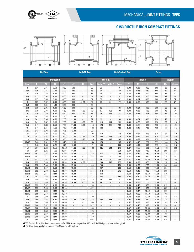
MECHANICAL JOINT FITTINGS | TEES
C153 DUCTILE IRON COMPACT FITTINGS
UL®
RE
GISTERED FIR
M
ISO 9001:2015CERTIFIED
10014257
Tyler Union
MJ Tee MJxFE Tee MJxSwivel Tee Cross
Domestic Weight Import Weight
Size T T1 H J1 J2 J3 MJ MJ x FE †MJ x S Cross T T1 H J1 MJ Cross3 0.34 0.34 3.50 3.50 5.50 – 26 29 – 31 0.33 0.33 3.00 3.00 28 35
4x3 0.35 0.34 3.50 4.00 6.50 – 35 34 – 39 0.34 0.33 3.50 4.00 30 344 0.35 0.35 4.00 4.00 6.50 – 37 39 – 45 0.34 0.34 4.00 4.00 32 40
6x3 0.37 0.34 4.00 4.00 6.50 – 51 54 – – 0.36 0.33 3.50 5.00 42 –6x4 0.37 0.35 5.00 6.00 8.00 – 52 57 – 62 0.36 0.34 4.00 5.00 46 57
6 0.37 0.37 6.00 6.00 8.00 10.50 62 69 61 72 0.36 0.36 5.00 5.00 56 758x3 0.39 0.34 4.00 6.50 9.00 – 56 – – – – – – – – –8x4 0.39 0.35 5.00 6.50 9.00 – 68 82 – 84 0.38 0.34 4.00 6.50 60 688x6 0.39 0.37 5.50 6.50 9.00 11.50 79 87 105 98 0.38 0.36 5.00 6.50 72 74
8 0.39 0.39 6.50 6.50 9.00 11.50 89 101 116 112 0.38 0.38 0.38 6.50 86 10510x3 0.41 0.34 4.00 7.50 11.00 – 80 – – – – – – – – –10x4 0.41 0.35 4.50 7.50 11.00 – 82 92 – 98 0.40 0.34 4.00 7.50 78 11210x6 0.41 0.37 5.50 7.50 11.00 13.00 99 116 114 121 0.40 0.36 5.00 7.50 90 11910x8 0.41 0.39 6.50 7.50 11.00 13.00 116 128 138 135 0.40 0.38 6.50 7.50 105 124
10 0.41 0.41 7.50 7.50 11.00 – 132 144 – 156 0.40 0.40 7.50 7.50 120 14512x3 0.43 0.34 4.00 8.75 12.00 – 99 – – – – – – – – –12x4 0.43 0.35 4.00 9.00 12.00 – 108 118 – 119 0.42 0.34 4.00 8.75 94 11912x6 0.43 0.37 5.00 9.00 12.00 14.25 119 133 132 138 0.42 0.34 4.00 8.75 110 12612x8 0.43 0.39 6.50 9.00 12.00 14.25 126 146 149 149 0.42 0.38 6.50 8.75 125 14912x10 0.43 0.41 7.50 8.75 12.00 – 159 174 – 187 0.42 0.40 7.50 8.75 140 179
12 0.43 0.43 8.75 8.75 12.00 – 171 198 – 202 0.42 0.42 8.75 8.75 160 21314x6 0.51 0.44 6.50 10.50 14.00 16.00 183 205 211 210 0.47 0.36 6.50 10.50 182 20014x8 0.51 0.45 7.50 10.50 14.00 – 211 – – 231 0.47 0.38 7.50 10.50 206 228
14x10 0.51 0.46 8.50 10.50 14.00 – 229 244 – 255 0.47 0.40 8.50 10.50 228 –14x12 0.51 0.47 9.50 10.50 14.00 – 245 284 – 269 0.47 0.42 9.50 10.50 234 –
14 0.51 0.51 10.50 10.50 14.00 – 281 291 – 299 0.47 0.47 10.50 10.50 280 29916x6 0.52 0.45 6.50 11.50 14.00 16.00 222 230 243 250 0.50 0.36 6.50 11.50 228 24016x8 0.52 0.46 7.50 11.50 15.00 – 245 248 – 264 0.50 0.38 7.50 11.50 248 38516x10 0.52 0.47 8.50 11.50 15.00 – 265 287 – 286 0.50 0.40 8.50 11.50 264 –16x12 0.52 0.48 9.50 11.50 15.00 – 277 312 – 312 0.50 0.42 9.50 11.50 280 –16x14 0.52 0.51 10.50 11.50 15.00 – 317 348 – – 0.50 0.47 10.50 11.50 316 –
16 0.52 0.52 11.50 11.50 15.00 – 337 324 – 451 0.50 0.50 11.50 11.50 322 –18x6 0.59 0.44 6.50 14.50 15.50 18.00 275 261 279 – 0.54 0.36 6.50 12.50 275 –18x8 0.59 0.45 7.50 14.50 14.50 – 280 351 – – 0.54 0.38 7.50 12.50 295 –18x10 0.59 0.47 8.50 12.50 – – 286 – – – 0.54 0.40 8.50 12.50 315 –18x12 0.59 0.49 9.50 12.50 – – 372 – – – 0.54 0.42 9.50 12.50 335 34818x14 0.59 0.56 10.50 12.50 – – 415 – – – 0.54 0.47 10.50 12.50 380 –18x16 0.59 0.57 11.50 12.50 – – 445 – – – 0.54 0.50 11.50 12.50 405 –
18 0.59 0.59 13.00 12.50 – – 490 – – – 0.54 0.54 12.50 12.50 435 34820x6 0.60 0.44 6.50 14.00 17.00 19.50 335 362 358 – 0.57 0.36 6.50 14.00 315 –20x8 0.60 0.45 8.00 14.00 – – 390 – – – 0.57 0.38 8.00 14.00 345 37920x10 0.60 0.47 9.00 14.00 – – 417 – – – 0.57 0.40 9.00 14.00 370 –20x12 0.60 0.49 10.00 14.00 – – 460 – – – 0.57 0.42 10.00 14.00 395 41320x14 0.60 0.56 11.00 14.00 – – 475 – – – 0.57 0.47 11.00 14.00 440 –20x16 0.60 0.57 12.00 14.00 – – 530 – – – 0.57 0.50 12.00 14.00 465 –20x18 0.60 0.59 13.00 14.00 – – 560 – – – 0.57 0.54 13.00 14.00 505 –
20 0.60 0.60 14.00 14.00 – – 605 – – – 0.57 0.57 14.00 14.00 535 –
NOTE: Contact TU Inside Sales representative for MJ Crosses larger than 16”. †MJxSwl Weights include swivel gland.NOTE: Other sizes available, contact Tyler Union for information.
6
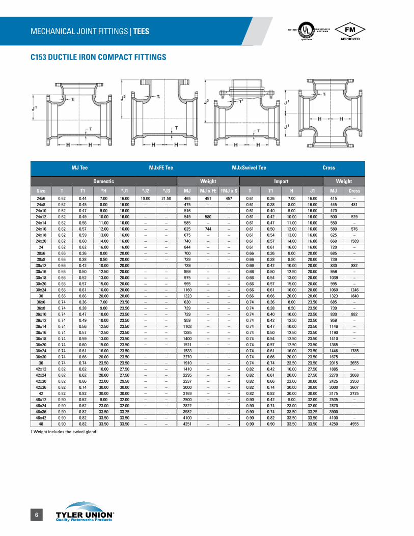
MECHANICAL JOINT FITTINGS | TEES
C153 DUCTILE IRON COMPACT FITTINGS
UL®
RE
GISTERED FIR
M
ISO 9001:2015CERTIFIED
10014257
Tyler Union
MJ Tee MJxFE Tee MJxSwivel Tee Cross
Domestic Weight Import Weight
Size T T1 *H *J1 *J2 *J3 MJ MJ x FE †MJ x S T T1 H J1 MJ Cross24x6 0.62 0.44 7.00 16.00 19.00 21.50 465 451 457 0.61 0.36 7.00 16.00 415 –24x8 0.62 0.45 8.00 16.00 – – 475 – – 0.61 0.38 8.00 16.00 445 481
24x10 0.62 0.47 9.00 16.00 – – 516 – – 0.61 0.40 9.00 16.00 470 –24x12 0.62 0.49 10.00 16.00 – – 549 580 – 0.61 0.42 10.00 16.00 500 52924x14 0.62 0.56 11.00 16.00 – – 585 – – 0.61 0.47 11.00 16.00 550 –24x16 0.62 0.57 12.00 16.00 – – 625 744 – 0.61 0.50 12.00 16.00 580 57624x18 0.62 0.59 13.00 16.00 – – 675 – – 0.61 0.54 13.00 16.00 625 –24x20 0.62 0.60 14.00 16.00 – – 740 – – 0.61 0.57 14.00 16.00 660 1589
24 0.62 0.62 16.00 16.00 – – 844 – – 0.61 0.61 16.00 16.00 720 –30x6 0.66 0.36 8.00 20.00 – – 700 – – 0.66 0.36 8.00 20.00 685 –30x8 0.66 0.38 8.50 20.00 – – 739 – – 0.66 0.38 8.50 20.00 739 –
30x12 0.66 0.42 10.00 20.00 – – 739 – – 0.66 0.42 10.00 20.00 830 88230x16 0.66 0.50 12.50 20.00 – – 959 – – 0.66 0.50 12.50 20.00 959 –30x18 0.66 0.52 13.00 20.00 – – 975 – – 0.66 0.54 13.00 20.00 1039 –30x20 0.66 0.57 15.00 20.00 – – 995 – – 0.66 0.57 15.00 20.00 995 –30x24 0.66 0.61 16.00 20.00 – – 1160 – – 0.66 0.61 16.00 20.00 1060 1246
30 0.66 0.66 20.00 20.00 – – 1323 – – 0.66 0.66 20.00 20.00 1323 184036x6 0.74 0.36 7.00 23.50 – – 630 – – 0.74 0.36 8.00 23.50 685 –36x8 0.74 0.38 9.00 23.50 – – 739 – – 0.74 0.38 8.50 23.50 739 –
36x10 0.74 0.47 10.00 23.50 – – 739 – – 0.74 0.40 10.00 23.50 830 88236x12 0.74 0.49 10.00 23.50 – – 959 – – 0.74 0.42 12.50 23.50 959 –36x14 0.74 0.56 12.50 23.50 – – 1103 – – 0.74 0.47 10.00 23.50 1146 –36x16 0.74 0.57 12.50 23.50 – – 1385 – – 0.74 0.50 12.50 23.50 1190 –36x18 0.74 0.59 13.00 23.50 – – 1400 – – 0.74 0.54 12.50 23.50 1410 –36x20 0.74 0.60 15.00 23.50 – – 1521 – – 0.74 0.57 12.50 23.50 1365 –36x24 0.74 0.61 16.00 23.50 – – 1533 – – 0.74 0.61 16.00 23.50 1446 178536x30 0.74 0.66 20.00 23.50 – – 2270 – – 0.74 0.66 20.00 23.50 1675 –
36 0.74 0.74 23.50 23.50 – – 1910 – – 0.74 0.74 23.50 23.50 2015 265542x12 0.82 0.62 10.00 27.50 – – 1410 – – 0.82 0.42 10.00 27.50 1885 –42x24 0.82 0.62 20.00 27.50 – – 2295 – – 0.82 0.61 20.00 27.50 2270 266842x30 0.82 0.66 22.00 29.50 – – 2337 – – 0.82 0.66 22.00 30.00 2425 295042x36 0.82 0.74 30.00 30.00 – – 3000 – – 0.82 0.74 30.00 30.00 3000 3607
42 0.82 0.82 30.00 30.00 – – 3169 – – 0.82 0.82 30.00 30.00 3175 372548x12 0.90 0.62 9.00 32.00 – – 2500 – – 0.90 0.42 9.00 32.00 2535 –48x24 0.90 0.62 23.00 32.00 – – 2822 – – 0.90 0.74 23.00 32.00 2870 –48x36 0.90 0.82 33.50 33.25 – – 3982 – – 0.90 0.74 33.50 33.25 3900 –48x42 0.90 0.82 33.50 33.50 – – 4100 – – 0.90 0.82 33.50 33.50 4100 –
48 0.90 0.82 33.50 33.50 – – 4251 – – 0.90 0.90 33.50 33.50 4250 4955
† Weight includes the swivel gland.

7
MECHANICAL JOINT FITTINGS | TEES
C153 DUCTILE IRON COMPACT FITTINGS
UL®
RE
GISTERED FIR
M
ISO 9001:2015CERTIFIED
10014257
Tyler Union
MJxPExMJ TEES
Domestic Import
Size T T1 *H *J1 *Z Weight T T1 *H *J1 *Z Weight6 0.37 0.37 5.00 5.00 11.50 57 0.37 0.37 8.00 8.00 16.00 57
8x6 0.39 0.37 5.50 6.50 11.50 79 0.39 0.37 9.00 9.00 17.00 798 0.39 0.39 6.50 6.50 12.50 81 0.38 0.38 9.00 9.00 17.00 77
10 0.41 0.41 7.50 7.50 13.00 133 0.40 0.40 11.00 11.00 19.00 120
H Z
J1T1
T
WYES/LATERAL
Size *A *Y T T1 Weights3 2.50 7.50 0.34 0.34 36
4x3 2.00 8.50 0.35 0.34 394 2.50 8.50 0.35 0.35 45
6x4 1.50 11.00 0.37 0.35 676 3.00 13.00 0.37 0.37 85
8x4 0.50 13.00 0.39 0.35 868x6 2.00 14.50 0.39 0.37 109
8 3.50 16.00 0.39 0.39 11710x4 0.00 15.00 0.41 0.35 11210x6 1.00 16.00 0.41 0.37 12910x8 2.50 17.00 0.41 0.39 162
10 3.50 19.00 0.41 0.41 19912x4 0.00 16.50 0.43 0.35 14112x6 1.50 18.50 0.43 0.37 17012x8 1.50 18.50 0.43 0.39 17712x10 3.00 20.00 0.43 0.41 216
12 4.50 22.50 0.43 0.43 26914 6.00 25.00 0.51 0.51 476
16x6 0.00 21.00 0.52 0.45 30016x8 0.50 22.50 0.52 0.46 34916x12 3.50 25.00 0.52 0.48 471
16 6.50 28.00 0.52 0.52 635
Y A
Y
T
T1
OFFSETS (MJ x MJ) or (MJxPE)
Import Weights
Size D L1 L2 MJ x MJ MJ x PE3 6.00 9.00 14.50 23 293 12.00 15.00 20.50 34 393 18.00 21.00 26.50 40 483 24.00 27.00 32.50 47 534 6.00 10.00 15.50 32 444 12.00 6.00 21.50 42 544 18.00 22.00 27.50 56 654 24.00 28.00 33.50 65 726 6.00 12.00 17.50 55 546 12.00 18.00 23.50 72 686 18.00 24.00 29.50 88 966 24.00 30.00 35.50 111 1178 6.00 13.00 18.50 79 788 12.00 19.00 24.50 103 1108 18.00 25.00 30.50 128 124
10 6.00 15.00 20.50 112 13010 12.00 21.00 26.50 148 17210 18.00 27.00 32.50 176 18912 6.00 17.00 22.50 157 –12 12.00 23.00 28.50 174 19812 18.00 29.00 34.50 210 27012 24.00 35.00 40.50 298 33412 30.00 41.00 46.50 283 205
L2L1
D
*Not in AWWA C153. “A” & “Y” are approximate dim.
Tyler Union does not recommend the use of wedge action restraints on plain end fittings.

8
SOLID SLEEVES
Domestic Import
Size T L1 L2Weight
T L1 L2Weight
Short Long Short Long3 0.34 7.50 12.00 13 22 0.33 7.50 12.00 12 174 0.35 7.50 12.00 19 25 0.34 7.50 12.00 15 206 0.37 7.50 12.00 28 37 0.36 7.50 12.00 23 298 0.39 7.50 12.00 38 49 0.38 7.50 12.00 31 45
10 0.41 7.50 12.00 48 68 0.40 7.50 12.00 45 6112 0.43 7.50 12.00 58 81 0.42 7.50 12.00 56 7614 0.56 9.50 15.00 107 153 0.47 9.50 15.00 94 12816 0.57 9.50 15.00 116 174 0.50 9.50 15.00 118 15918 0.68 9.50 15.00 154 207 0.54 9.00 15.00 145 20020 0.69 9.50 15.00 200 249 0.57 9.00 15.00 173 23624 0.75 9.50 15.00 232 323 0.61 9.00 15.00 226 30630 0.74 15.00 24.00 549 640 0.66 15.00 24.00 472 63436 0.74 15.00 24.00 725 868 0.74 15.00 24.00 673 88942 0.82 – 24.00 – 1146 0.82 15.00 24.00 887 115048 0.90 – 24.00 – 1431 0.90 15.00 24.00 1136 1435
MECHANICAL JOINT FITTINGS | PLUGS / CAPS / SOLID SLEEVE
C153 DUCTILE IRON COMPACT FITTINGS
UL®
RE
GISTERED FIR
M
ISO 9001:2015CERTIFIED
10014257
Tyler Union
SOLID & TAPPED PLUGS & CAPS
Domestic Import
Size T Max. Tap
WeightT
Weight
Plugs Caps Plugs Caps3 0.46 2 9 8 0.33 8 84 0.46 2 9 10 0.34 10 96 0.46 2 13 18 0.36 16 158 0.46 2 25 26 0.38 26 2210 0.56 2 36 32 0.40 36 3212 0.56 2 47 46 0.42 46 4214 0.62 2 76 85 0.47 75 6616 0.62 2 98 94 0.50 95 9218 0.65 2 138 121 0.54 121 11420 0.66 2 158 149 0.57 135 12524 0.68 2 202 232 0.61 296 19830 0.66 2 426 345 0.66 355 34536 0.74 2 560 626 0.74 688 62842 0.82 2 1091 723 0.82 – –48 0.90 2 1455 974 0.90 – –
T TT T
TAPPING SLEEVE FOR CAST IRON/DUCTILE IRON
Size A B C D E F Min. Max Weight6X4 5.016 0.250 7.50 15.75 8.00 12.75 6.85 7.15 104
6 7.016 0.312 9.50 15.75 8.00 12.75 6.85 7.15 1088X4 5.016 0.250 7.50 16.50 9.00 13.50 9.00 9.35 1348X6 7.016 0.312 9.50 16.50 9.00 13.50 9.00 9.35 140
8 9.016 0.312 11.75 16.50 9.00 13.50 9.00 9.35 14810X4 5.016 0.250 7.50 24.00 11.00 20.75 11.04 11.45 23610X6 7.016 0.312 9.50 24.00 11.00 20.75 11.04 11.45 24010X8 9.016 0.312 11.75 24.00 11.00 20.75 11.04 11.45 246
10 11.016 0.312 14.25 24.00 11.00 20.75 11.04 11.45 25712X4 5.016 0.250 7.50 26.50 12.00 23.25 13.14 13.56 27312X6 7.016 0.312 9.50 26.50 12.00 23.25 13.14 13.56 28612X8 9.016 0.312 11.75 26.50 12.00 23.25 13.14 13.56 29212X10 11.016 0.312 14.25 26.50 12.00 23.25 13.14 13.56 303
12 13.016 0.312 17.00 26.50 12.00 23.25 13.14 13.56 320
A.
3-12 14-48 3-12 14-48 L1
T T
L2
Note: Visit www.tylerunion.com for assembly instructions.Tapping sleeve is assembled with gland and gasket.
9
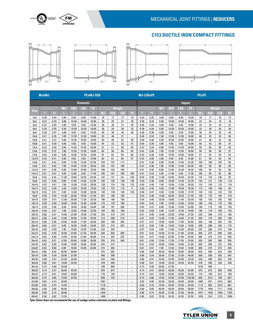
MECHANICAL JOINT FITTINGS | REDUCERS
C153 DUCTILE IRON COMPACT FITTINGS
UL®
RE
GISTERED FIR
M
ISO 9001:2015CERTIFIED
10014257
Tyler Union
MJxMJ PExMJ-SEB MJ-LEBxPE PExPE
Domestic Import
SizeMJ SEB LEB PE Weight MJ SEB LEB PE Weight
T T1 L L L L MJ SEB LEB PE T T1 L L L L MJ SEB LEB PE4x3 0.35 0.34 3.00 8.50 8.50 14.00 18 17 17 18 0.34 0.33 3.00 8.50 8.50 14.00 18 17 18 146x3 0.37 0.34 5.00 10.50 10.50 16.00 28 25 27 20 0.36 0.33 5.00 10.50 10.50 16.00 22 24 19 166x4 0.37 0.35 4.00 9.50 9.50 15.00 28 26 27 26 0.36 0.34 4.00 9.50 9.50 15.00 24 25 25 228x4 0.39 0.35 5.00 10.50 10.50 16.00 36 34 36 33 0.38 0.34 5.00 10.50 10.50 16.00 32 30 34 308x6 0.39 0.37 4.00 9.50 9.50 15.00 39 38 39 30 0.38 0.36 4.00 9.50 9.50 15.00 36 35 32 30
10x4 0.41 0.35 7.00 12.50 12.50 18.00 53 46 51 – 0.40 0.34 7.00 12.50 12.50 18.00 46 43 43 4610x6 0.41 0.37 5.00 10.50 10.50 16.00 59 48 52 49 0.40 0.36 5.00 10.50 10.50 16.00 47 46 42 4610x8 0.41 0.39 4.00 9.50 9.50 15.00 54 52 52 47 0.40 0.38 4.00 9.50 9.50 15.00 50 42 50 4712x4 0.43 0.35 9.00 14.50 14.50 20.00 67 61 68 60 0.42 0.34 9.00 14.50 14.50 20.00 58 60 60 5812x6 0.43 0.37 7.00 12.50 12.50 18.00 64 58 66 54 0.42 0.36 7.00 12.50 12.50 18.00 58 58 58 5712x8 0.43 0.39 5.00 10.50 10.50 16.00 57 62 65 60 0.42 0.38 5.00 10.50 10.50 16.00 57 54 55 54
12x10 0.43 0.41 4.00 9.50 9.50 15.00 63 61 65 57 0.42 0.40 4.00 9.50 9.50 15.00 61 59 59 5414x6 0.51 0.44 9.00 17.00 14.50 22.50 104 107 112 – 0.47 0.36 9.00 16.90 14.50 22.30 100 100 104 9314x8 0.51 0.45 7.00 15.00 12.50 20.50 104 107 108 – 0.47 0.38 7.00 14.90 12.40 20.30 100 98 98 94
14x10 0.51 0.46 5.00 13.00 10.50 18.50 100 102 100 – 0.47 0.40 5.00 12.90 10.40 18.30 100 94 92 9014x12 0.51 0.47 4.00 12.00 9.50 17.50 100 101 100 100 0.47 0.42 4.00 11.90 9.40 17.30 100 90 92 8816x6 0.52 0.45 11.00 19.00 16.50 24.50 132 131 141 128 0.50 0.36 11.00 18.90 16.50 24.30 124 125 136 9316x8 0.52 0.46 9.00 17.00 14.50 22.50 136 128 136 136 0.50 0.38 9.00 16.90 14.40 22.30 124 121 128 11916x10 0.52 0.47 7.00 15.00 12.50 20.50 128 124 128 123 0.50 0.40 7.00 15.00 12.50 20.50 124 105 123 11916x12 0.52 0.48 5.00 13.00 10.50 18.50 120 123 119 11 0.50 0.42 5.00 12.90 10.50 18.30 112 109 108 9916x14 0.52 0.51 4.00 12.00 12.00 20.00 140 139 138 133 0.50 0.47 4.00 12.00 12.00 19.70 140 126 132 12918x8 0.59 0.45 14.00 22.00 19.50 27.50 201 180 195 – 0.54 0.38 13.00 20.00 19.50 27.40 190 170 195 170
18x10 0.59 0.47 12.00 20.00 17.50 25.50 196 180 185 – 0.54 0.40 10.00 18.00 17.40 25.50 195 165 185 16018x12 0.59 0.49 10.00 18.00 15.50 23.50 175 170 190 – 0.54 0.42 7.00 15.50 14.00 19.50 180 150 175 15018x14 0.59 0.56 8.00 16.00 16.00 24.00 180 181 200 – 0.54 0.47 6.00 15.00 15.00 23.00 190 175 190 16018x16 0.59 0.57 7.00 15.00 15.00 23.00 194 180 190 – 0.54 0.50 5.00 12.50 12.50 18.00 195 170 190 14520x10 0.60 0.47 14.00 22.00 19.40 27.50 225 210 210 – 0.57 0.40 14.00 22.00 19.00 27.50 220 200 210 18020x12 0.60 0.49 12.00 20.00 17.50 25.50 214 208 210 – 0.57 0.42 12.00 17.50 16.00 21.50 205 170 205 19020x14 0.60 0.56 10.00 18.00 17.80 26.00 208 198 205 – 0.57 0.47 10.00 18.00 17.90 26.00 200 190 205 19520x16 0.60 0.57 8.00 16.00 15.80 24.00 225 215 222 – 0.57 0.50 7.00 13.50 13.50 19.00 200 200 185 17020x18 0.60 0.59 7.00 15.00 15.00 23.00 233 220 – – 0.57 0.54 4.00 12.00 12.00 20.00 225 200 215 19024x12 0.62 0.49 16.00 24.00 21.40 29.50 320 302 300 – 0.61 0.42 16.00 21.50 21.00 22.50 305 275 290 24024x14 0.62 0.56 14.00 22.00 21.80 30.00 314 325 322 – 0.61 0.47 14.00 22.00 21.90 25.00 306 310 315 29524x16 0.62 0.57 12.00 20.00 19.80 28.00 325 319 340 – 0.61 0.50 12.00 17.50 17.50 23.00 320 285 285 28524x18 0.62 0.59 10.00 18.00 18.00 26.00 325 310 – – 0.61 0.54 10.00 18.00 18.00 21.00 305 300 310 29024x20 0.62 0.60 8.00 16.00 16.00 24.00 315 305 – – 0.61 0.57 7.00 13.50 13.50 14.00 300 270 275 24030x16 0.66 0.50 30.00 39.00 – – 475 565 – – 0.66 0.50 30.00 39.00 39.00 48.00 633 565 623 55530x18 0.66 0.54 28.00 37.00 – – 495 590 – – 0.66 0.54 28.00 37.00 37.00 46.00 658 590 635 56730x20 0.66 0.57 24.00 33.00 – – 525 560 – – 0.66 0.57 24.00 33.00 33.00 42.00 628 560 603 53530x24 0.66 0.61 10.00 24.50 – – 478 495 – – 0.66 0.61 10.00 24.50 24.50 33.50 478 495 526 45836x16 0.74 0.50 30.00 – – – 789 890 – – 0.74 0.50 30.00 27.00 – – 1016 595 – –36x20 0.74 0.57 36.00 45.00 – – 970 874 – – 0.74 0.57 36.00 45.00 45.00 54.00 975 874 950 84936x24 0.74 0.61 19.00 33.00 – – 770 746 – – 0.74 0.61 19.00 33.00 33.00 42.00 770 746 810 70936x30 0.74 0.66 15.50 24.50 – – 838 725 – – 0.74 0.66 15.50 24.50 24.50 725.00 650 33.5 758 65742x30 0.82 0.74 20.00 – – – 1067 – – – 0.82 0.66 20.00 29.00 29.00 38.00 1083 931 1015 86342x36 0.82 0.74 15.50 – – – 1116 – – – 0.82 0.74 15.50 24.50 24.50 33.50 1114 962 1013 86148x30 0.90 0.66 40.00 – – – 1852 – – – 0.90 0.66 40.00 49.00 49.00 58.00 1779 1594 1711 152648x36 0.90 0.74 28.00 – – – 1632 – – – 0.90 0.74 28.00 37.00 37.00 46.00 1641 1456 1540 135548x42 0.90 0.82 15.50 – – – 1486 – – – 0.90 0.82 15.50 24.50 24.50 33.50 1426 1241 1274 1089
L
T T1 T1
L
T T1 TT
L
T1
L
Tyler Union does not recommend the use of wedge action restraints on plain end fittings.
10
MECHANICAL JOINT FITTINGS | ADAPTERS
C153 DUCTILE IRON COMPACT FITTINGS
UL®
RE
GISTERED FIR
M
ISO 9001:2015CERTIFIED
10014257
Tyler Union
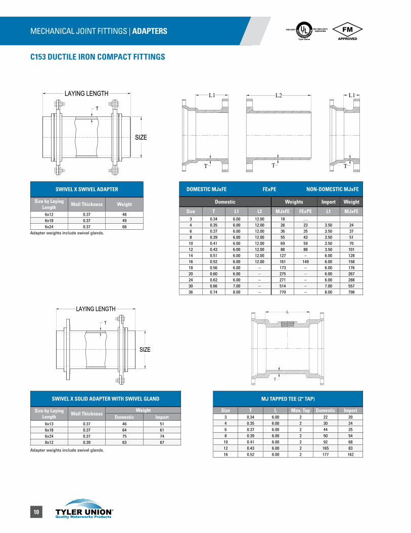
SWIVEL X SWIVEL ADAPTER
Size by Laying Length Wall Thickness Weight
6x12 0.37 486x18 0.37 496x24 0.37 68
SWIVEL X SOLID ADAPTER WITH SWIVEL GLAND
Size by Laying Length Wall Thickness
WeightDomestic Import
6x13 0.37 46 516x18 0.37 64 616x24 0.37 75 748x12 0.39 63 67
DOMESTIC MJxFE FExPE NON-DOMESTIC MJxFE
Domestic Weights Import Weight
Size T L1 L2 MJxFE FExPE L1 MJxFE3 0.34 6.00 12.00 18 …4 0.35 6.00 12.00 26 23 3.50 246 0.37 6.00 12.00 36 35 3.50 378 0.39 6.00 12.00 55 43 3.50 51
10 0.41 6.00 12.00 69 59 3.50 7012 0.43 6.00 12.00 88 88 3.50 10114 0.51 6.00 12.00 127 – 6.00 12816 0.52 6.00 12.00 161 149 6.00 15818 0.56 6.00 – 173 – 6.00 17620 0.60 6.00 – 275 – 6.00 26724 0.62 6.00 – 271 – 6.00 28830 0.66 7.00 – 514 – 7.00 55736 0.74 8.00 – 770 – 8.00 798
L1
T
L2
T
L1
T
MJ TAPPED TEE (2" TAP)
Size T L Max. Tap Domestic Import3 0.34 6.00 2 22 204 0.35 6.00 2 30 246 0.37 6.00 2 44 358 0.39 6.00 2 50 5410 0.41 6.00 2 92 6812 0.43 6.00 2 165 8316 0.52 6.00 2 177 162
L
T
Adapter weights include swivel glands.
Adapter weights include swivel glands.
11
MECHANICAL JOINT FITTINGS | GLANDS
C153 DUCTILE IRON COMPACT FITTINGS
UL®
RE
GISTERED FIR
M
ISO 9001:2015CERTIFIED
10014257
Tyler Union
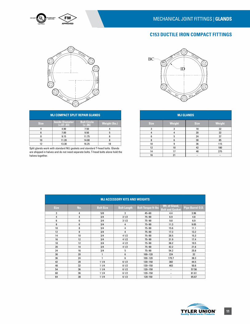
MJ COMPACT SPLIT REPAIR GLANDS
Size Inside Diameter (+.07-.03)
Bolt Circle(+-.06) Weight (lbs.)
4 4.90 7.50 46 7.00 9.50 58 9.15 11.75 610 11.20 14.00 812 13.30 16.25 18
MJ GLANDS
Size Weight Size Weight
3 3 18 224 4 20 326 5 24 378 6 30 8510 9 36 11512 10 42 18014 17 48 27516 21 – –
ID
BCC-153
TYLERGLAND
UNION8 DI
USA
350
C-153
TYLE
RGLAND
UN
ION
8 DIUSA
350
MJ ACCESSORY KITS AND WEIGHTS
Size No. Bolt Size Bolt Length Bolt Torque ft-lbs Wt. of Gland, Bolt and Gasket Pipe Barrel O.D.
3 4 5/8 3 45–60 4.4 3.964 4 3/4 3 1/2 75–90 6.9 4.86 6 3/4 3 1/2 75–90 9.8 6.98 6 3/4 4 75–90 11.3 9.0510 8 3/4 4 75–90 15.6 11.112 8 3/4 4 75–90 17.3 13.214 10 3/4 4 1/2 75–90 26.5 15.316 12 3/4 4 1/2 75–90 31.9 17.418 12 3/4 4 1/2 75–90 36.2 19.520 14 3/4 4 1/2 75–90 42.2 21.624 16 3/4 5 75–90 54.2 25.830 20 1 6 100–120 224 3236 24 1 6 100–120 179.7 38.342 28 1 1/4 6 1/2 120–150 382 44.548 32 1 1/4 6 1/2 120–150 463 50.854 36 1 1/4 6 1/2 120–150 – 57.5660 36 1 1/4 6 1/2 120–150 – 61.6164 38 1 1/4 6 1/2 120-150 – 65.67
Split glands work with standard MJ gaskets and standard T-head bolts. Glands are shipped in halves and do not need separate bolts. T-head bolts alone hold the halves together.
12
C153 DUCTILE IRON COMPACT FITTINGS
MECHANICAL JOINT FITTINGS | DUAL PURPOSE CUTTING-IN SLEEVE UL®
RE
GISTERED FIR
M
ISO 9001:2015CERTIFIED
10014257
Tyler Union
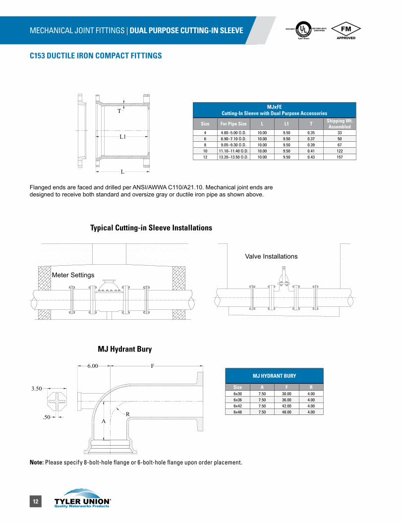
MJxFE Cutting-In Sleeve with Dual Purpose Accessories
Size For Pipe Size L L1 T Shipping Wt. Assembled
4 4.80–5.00 O.D. 10.00 9.50 0.35 336 6.90–7.10 O.D. 10.00 9.50 0.37 508 9.05–9.30 O.D. 10.00 9.50 0.39 6710 11.10–11.40 O.D. 10.00 9.50 0.41 12212 13.20–13.50 O.D. 10.00 9.50 0.43 157
L1
T
L
Typical Cutting-in Sleeve Installations
Meter Settings
Valve Installations
A
F6.00
R
3.50
.50
Note: Please specify 8-bolt-hole flange or 6-bolt-hole flange upon order placement.
Flanged ends are faced and drilled per ANSI/AWWA C110/A21.10. Mechanical joint ends are designed to receive both standard and oversize gray or ductile iron pipe as shown above.
MJ Hydrant Bury
MJ HYDRANT BURY
Size A F R6x30 7.50 30.00 4.006x36 7.50 36.00 4.006x42 7.50 42.00 4.006x48 7.50 48.00 4.00

13
MECHANICAL JOINT FITTINGS
C110 DUCTILE IRON FULL BODY FITTINGS
UL®
RE
GISTERED FIR
M
ISO 9001:2015CERTIFIED
10014257
Tyler Union
SAMPLE SPECIFICATIONS (Current ANSI/AWWA revisions apply)
Mechanical joint water main fittings with accessories 2” through 48” shall be manufactured from ductile iron in accordance with and meet all applicable terms and provisions of standards ANSI/AWWA C110/A21.10 and ANSI/AWWA C111/A21.11. Ductile iron mechanical joint fittings 2” through 24” shall be rated for 350 psi working pressure. All ductile iron mechanical joint fittings 30” through 48” shall be rated for 250 psi working pressure. Flanged ductile iron fittings in 24” (610 mm) and smaller sizes may be rated for 350 psi (2,413 kPa) with the use of special (annular ring or comparable) gaskets.
NOTE: EXCEPTIONS: Mechanical joint fittings with flanged branches and 14” and larger caps and plugs are rated for water pressure of 250 psi.
NOTE: Installation per AWWA C600 and AWWA C651, current revision.
NOTE: Fittings are cement lined and seal coated in accordance with ANSI/AWWA C104/A21.4. Fittings are also available double cement lined, bare or epoxy coated. Coated and lined fittings meet requirements of NSF-61, NSF-372 & Annex G.
Nominal Joint Dimensions in Inches
Size A B C D F ø X J K1 K2 L M N O S*2 2.50 2.50 3.39 3.50 2.61 28° 3/4 4.75 6.25 6.25 0.75 0.62 1.12 0.31 0.443 3.96 2.50 4.84 4.94 4.06 28° 3/4 6.19 7.69 7.69 0.94 0.62 1.37 0.31 0.524 4.80 2.50 5.92 6.02 4.90 28° 7/8 7.50 9.12 9.12 1.00 0.75 1.50 0.31 0.656 6.90 2.50 8.02 8.12 7.00 28° 7/8 9.50 11.12 11.12 1.06 0.88 1.63 0.31 0.708 9.05 2.50 10.17 10.27 9.15 28° 7/8 11.75 13.37 13.37 1.12 1.00 1.75 0.31 0.7510 11.10 2.50 12.22 12.34 11.20 28° 7/8 14.00 15.69 15.62 1.19 1.00 1.75 0.31 0.8012 13.20 2.50 14.32 14.44 13.30 28° 7/8 16.25 17.94 17.88 1.25 1.00 1.75 0.31 0.8514 15.30 3.50 16.40 16.54 15.44 28° 7/8 18.75 20.31 20.25 1.31 1.25 2.00 0.31 0.8916 17.40 3.50 18.50 18.64 17.54 28° 7/8 21.00 22.56 22.50 1.38 1.31 2.06 0.31 0.9718 19.50 3.50 20.60 20.74 19.64 28° 7/8 23.25 24.83 24.75 1.44 1.38 2.13 0.31 1.0520 21.60 3.50 22.70 22.84 21.74 28° 7/8 25.50 27.08 27.00 1.50 1.44 2.19 0.31 1.1224 25.80 3.50 26.90 27.04 25.94 28° 7/8 30.00 31.58 31.50 1.62 1.56 2.31 0.31 1.2230 32.00 4.00 33.29 33.46 32.17 20° 1 1/8 36.88 39.12 39.12 1.81 2.00 2.75 0.38 1.5036 38.30 4.00 39.59 39.76 38.47 20° 1 1/8 43.75 46.00 46.00 2.00 2.00 2.75 0.38 1.8042 44.50 4.00 45.79 45.96 44.67 20° 1 3/8 50.62 53.12 53.12 2.00 2.00 2.75 0.38 1.9548 50.80 4.00 52.09 52.26 50.97 20° 1 3/8 57.50 60.00 60.00 2.00 2.00 2.75 0.38 2.20
ANSI/AWWA C110 Mechanical Joint Fittings
*Not included in AWWA C110.

14
MECHANICAL JOINT FITTINGS | BENDS
C110 DUCTILE IRON FULL BODY FITTINGS
UL®
RE
GISTERED FIR
M
ISO 9001:2015CERTIFIED
10014257
Tyler Union
90° (1/4) BENDS
Domestic Import
Size R Y ZWeight Weight
MJxMJ MJxPE MJxFE MJ MJxPE*2 2.30 3.30 – 16 – – – –3 4.00 5.50 13.50 26 36 – 35 354 4.50 6.50 14.50 56 53 47 55 506 6.00 8.00 16.00 88 80 75 88 978 7.00 9.00 17.00 123 119 118 136 15310 9.00 11.00 19.00 182 181 170 190 19012 10.00 12.00 20.00 280 252 246 255 25514 11.50 14.00 22.00 380 – – 400 –16 12.50 15.00 23.00 552 – 465 480 41018 14.00 16.50 24.50 625 600 591 641 57720 15.50 18.00 26.00 862 775 – 725 65024 18.50 22.00 30.00 1423 1301 1150 1020 98530 21.50 25.00 33.00 1942 1920 – 1843 158536 24.50 28.00 36.00 2629 2310 – 2513 231042 27.50 31.00 – 3410 – – 3410 –48 30.50 34.00 – 4595 – – 4595 –
45° (1/8) BENDS
Domestic Import
Size R Y ZWeight Weight
MJ MJXFE MJXPE MJ MJxPE*2 1.96 1.80 – 12 – – – –3 3.62 3.00 11.00 30 – – 30 304 4.81 4.00 12.00 53 48 45 49 486 7.25 5.00 13.00 77 60 69 77 818 8.44 5.50 13.50 110 107 111 117 12310 10.88 6.50 14.50 156 148 167 155 16812 13.25 7.50 15.50 214 215 196 223 21514 12.06 7.50 15.50 300 – – 270 –16 13.25 8.00 16.00 391 – 349 335 32018 14.50 8.50 16.50 527 416 455 467 39520 16.88 9.50 17.50 631 543 537 527 50024 18.12 11.00 19.00 880 1099 825 754 71530 27.75 15.00 23.00 1898 – 1510 1451 127536 35.00 18.00 26.00 2372 – 1930 2176 193042 42.25 21.00 – 3020 – – 2955 –48 49.50 24.00 – 4170 – – 4080 –
22 1/2° (1/16) BENDS
Domestic Import
Size R Y ZWeight Weight
MJ MJXFE* MJXPE MJ MJxPE3 7.56 3.00 11.00 30 – – 30 –4 10.06 4.00 12.00 52 – – 51 456 15.06 5.00 13.00 77 71 70 75 708 17.62 5.50 13.50 110 107 163 108 10810 22.62 6.50 14.50 156 155 163 159 16012 27.62 7.50 15.50 214 215 212 199 22014 25.12 7.50 15.50 300 – – 275 –16 27.62 8.00 16.00 391 344 334 318 32518 30.19 8.50 16.50 527 422 423 430 40520 35.19 9.50 17.50 631 – 575 545 50524 37.69 11.00 19.00 880 800 930 758 72530 57.81 15.00 23.00 1898 – 1540 1400 140036 72.88 18.00 26.00 2372 – 1970 2121 197042 88.00 21.00 – 3020 – – 3020 –48 103.06 24.00 – 4170 – – 4170 –
YY
Y Y
Y
Z
R
R R
Y Y
R
YZ
R
Y Y
R
Y Y
R
YZ
R
Y Y
R
90° (1/4) MJ
90° (1/4) MJxFE
90° (1/4) MJxPE
45° (1/8) MJ
22½° (1/16) MJ
45° (1/8) MJxFE
22½° (1/16) MJxFE
45° (1/8) MJxPE
22½° (1/16) MJxPE
*Not included in ASSA C110.
Tyler Union does not recommend the use of wedge action restraints on plain end fittings

15
MECHANICAL JOINT FITTINGS | BENDS
C110 DUCTILE IRON FULL BODY FITTINGS
UL®
RE
GISTERED FIR
M
ISO 9001:2015CERTIFIED
10014257
Tyler Union
11 1/4° (1/32) BENDS
Domestic Import
Size R Y ZWeight Weight
MJ MJxFE MJxPE MJ MJxPE3 15.25 3.00 11.00 30 – – 29 –4 20.31 4.00 12.00 52 – 45 51 –6 30.50 5.00 13.00 65 71 70 75 –8 35.50 5.50 13.50 104 105 105 108 10510 45.69 6.50 14.50 171 – – 160 –12 55.81 7.50 15.50 221 215 – 220 –14 50.75 7.50 15.50 305 --- – 275 –16 55.81 8.00 16.00 405 345 – 345 –18 60.94 8.50 16.50 525 422 – 450 –20 71.06 9.50 17.50 644 – – 540 –24 76.12 11.00 19.00 996 800 972 762 73030 116.75 15.00 23.00 1410 – 1305 1407 130536 147.25 18.00 26.00 2397 – 2185 2161 198042 177.69 21.00 – 3035 – – 3740 –48 208.12 24.00 – 4190 – – 4190 –
NOTE: Includes 2 swivel glands. *Not included in AWWA C110.
90° (1/4) SWIVEL X SWIVEL BENDS
Size Wall Thickness A B C D E F R *Weight
6 0.55 10.50 15.50 7.10 11.12 6.90 8.02 6.00 1068 0.60 11.50 16.50 9.20 13.37 9.05 10.17 7.00 156
OFFSETS
Size D L L2Weight
MJ X MJ MJ X PE4 6.00 19.00 27.00 – 824 12.00 22.00 30.00 85 804 18.00 30.00 38.00 105 –4 24.00 26.00 34.00 126 1256 6.00 20.00 28.00 114 1056 12.00 26.00 34.00 148 1436 18.00 33.00 41.00 188 1766 24.00 24.00 32.00 182 1608 6.00 21.00 29.00 177 1558 12.00 28.00 36.00 231 1958 18.00 35.00 43.00 287 2828 24.00 36.00 44.00 280 28510 12.00 30.00 38.00 347 28010 18.00 38.00 46.00 340 34010 24.00 38.00 46.00 420 –12 12.00 37.00 45.00 420 42012 18.00 48.00 56.00 520 52012 24.00 48.00 56.00 649 63016 12.00 40.00 48.00 715 –16 18.00 50.00 58.00 850 83020 12.00 40.00 48.00 1025 –20 18.00 48.00 60.00 1362 –
Y Y
R
Y Z
R
Y Y
R
11¼° (1/32) MJxFE
11¼° (1/32) MJxPE 11¼° (1/32) MJ
L2L1
D
Tyler Union does not recommend the use of wedge action restraints on plain end fittings.
16
MECHANICAL JOINT FITTINGS | TEES UL®
RE
GISTERED FIR
M
ISO 9001:2015CERTIFIED
10014257
Tyler Union
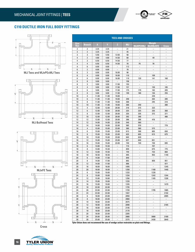
TEES AND CROSSES
Size Run Branch X Y Z MJ Weight
MJXPEXMJ MJXMJXFE Cross2 2 3.25 3.25 – 21 – – –3 2 3.25 3.25 – 45 – – –3 3 5.50 5.50 13.50 58 – – –4 2 4.80 4.80 14.50 68 – 49 –4 3 6.50 6.50 14.50 77 – – –4 4 6.50 6.50 14.50 78 75 76 –4 6 8.00 8.00 – 112 – – –6 2 8.00 8.00 – 78 – – –6 3 8.00 8.00 16.00 98 – – –6 4 8.00 8.00 16.00 110 – 109 –6 6 8.00 8.00 16.00 119 120 141 1606 8 9.00 9.00 – 158 – – –8 3 9.00 9.00 17.00 155 – – –8 4 9.00 9.00 17.00 157 – 150 1858 6 9.00 9.00 17.00 175 170 182 2058 8 9.00 9.00 17.00 199 180 194 255
10 4 11.00 11.00 19.00 – – 229 –10 6 11.00 11.00 19.00 258 – 264 28510 8 11.00 11.00 19.00 268 – 245 31010 10 11.00 11.00 19.00 300 250 – 38012 4 12.00 12.00 20.00 318 315 323 –12 6 12.00 12.00 20.00 325 325 335 36012 8 12.00 12.00 20.00 335 335 372 37112 10 12.00 12.00 20.00 392 390 – 48612 12 12.00 12.00 20.00 396 396 476 –14 12 14.00 14.00 22.00 540 560 – –14 14 14.00 14.00 22.00 585 570 – 77916 4 15.00 15.00 23.00 580 580 575 –16 6 15.00 15.00 23.00 615 590 605 65016 8 15.00 15.00 23.00 625 605 615 67516 10 15.00 15.00 23.00 645 620 – –16 12 15.00 15.00 23.00 627 640 651 –16 16 15.00 15.00 23.00 740 720 730 89518 6 13.00 15.50 – 710 – 707 –18 8 13.00 15.50 – 659 – 675 77518 12 13.00 15.50 – 749 – 733 86018 18 16.50 16.50 – 945 – 953 114020 6 14.00 17.00 – 849 – – –20 8 14.00 17.00 – 892 – 859 95120 12 14.00 17.00 – 896 – – 97720 16 18.00 18.00 – 1095 – – 124520 20 18.00 18.00 – 1258 – 1168 144024 6 15.00 19.00 – 1233 – 1228 –24 8 15.00 19.00 – 1234 – 1242 124424 12 15.00 19.00 – 1256 – 1165 132624 14 15.00 19.00 – 1220 – – –24 16 15.00 19.00 – 1245 – – 147924 18 22.00 22.00 – 1735 – – –24 20 22.00 22.00 – 1720 – 1795 196524 24 22.00 22.00 – 1947 – – 219230 6 18.00 23.00 – 2050 – – 208530 8 18.00 23.00 – 2060 – – –30 10 18.00 23.00 – 2075 – – –30 12 18.00 23.00 – 2090 – – 216530 16 18.00 23.00 – 2145 – – –30 18 18.00 23.00 – 2170 – – –30 20 18.00 23.00 – 2205 – – –30 24 25.00 25.00 – 2880 – 3080 318030 30 25.00 25.00 – 2275 – 2430 3640
MJ Tees and MJxPExMJ Tees
MJ Bullhead Tees
MJxFE Tees
Cross
X X
Y
Y
X X
Y
Z
X
Y
X
Y
X X
C110 DUCTILE IRON FULL BODY FITTINGS
Tyler Union does not recommend the use of wedge action restraints on plain end fittings.

17
MECHANICAL JOINT FITTINGS | TEES
C110 DUCTILE IRON FULL BODY FITTINGS
UL®
RE
GISTERED FIR
M
ISO 9001:2015CERTIFIED
10014257
Tyler Union
TEES AND CROSSES (Continued)
Size Run Branch X Y Z MJ Weight
MJXPEXMJ MJXMJXFE Cross36 6 20.00 26.00 – 2439 – – –36 8 20.00 26.00 – 2444 – – –36 10 20.00 26.00 – 2535 – 2550 –36 12 20.00 26.00 – 2541 – – –36 14 20.00 26.00 – 2570 – 2450 –36 16 20.00 26.00 – 2585 – – 437036 18 20.00 26.00 – 2610 – – 342036 20 20.00 26.00 – 2635 – 2660 345536 24 20.00 26.00 – 2792 – – 349536 30 28.00 28.00 – 3545 – – 353536 36 28.00 28.00 – 3450 – – 359042 12 23.00 30.00 – 3555 – – 369042 14 23.00 30.00 – 3575 – – 481542 16 23.00 30.00 – 3595 – – 643042 18 23.00 30.00 – 3615 – – 692042 20 23.00 30.00 – 3640 – – 466542 24 23.00 30.00 – 3690 – – 469542 30 31.00 31.00 – 4650 – – 473542 36 31.00 31.00 – 4880 – – 477542 42 31.00 31.00 – 6320 – – 482548 12 26.00 34.00 – 4870 – – –48 14 26.00 34.00 – 4885 – – –48 16 26.00 34.00 – 4905 – – –48 18 26.00 34.00 – 4925 – – –48 20 26.00 34.00 – 4950 – – –48 24 26.00 34.00 – 4995 – – 492048 30 26.00 34.00 – 5140 – – 521048 36 34.00 34.00 – 6280 – – 650048 42 34.00 34.00 – 8130 – – 853048 48 34.00 34.00 – 8420 – – 9095
MJ X MJ X SWIVEL TEE
Size X Y Weight6 8.00 10.50 150
8x6 9.00 11.50 1998 9.00 11.50 210
10x6 11.00 13.50 26712x6 12.00 14.50 34616x6 15.00 17.50 61916x8 15.00 17.50 64930x6 18.00 24.50 2070
MJ TAPPED TEE (2” TAP)
Domestic Import
size L Max.Tap Weight T L Max. Tap Weight3 8.00 2 40 0.33 6.00 2 184 8.00 2 51 0.34 6.00 2 246 8.00 2 73 0.36 6.00 2 428 8.00 2 104 0.38 6.00 2 52
10 8.00 2 130 0.40 6.00 2 6412 8.00 2 180 0.42 6.00 2 81
L
T
MJ Tapped Tees (2” TAP) MJxMJxSwivel Tees
MJ Tees AND MJxPExMJ Tees
MJxFE Tees
CrossX X
Y
Y
X X
Y
Z
Y
X X
X X
Y
All weights shown include the swivel gland.Tyler Union does not recommend the use of wedge action restraints on plain end fittings
18
PUSH-ON MECHANICAL JOINT FITTINGS | REDUCERS UL®
RE
GISTERED FIR
M
ISO 9001:2015CERTIFIED
10014257
Tyler Union
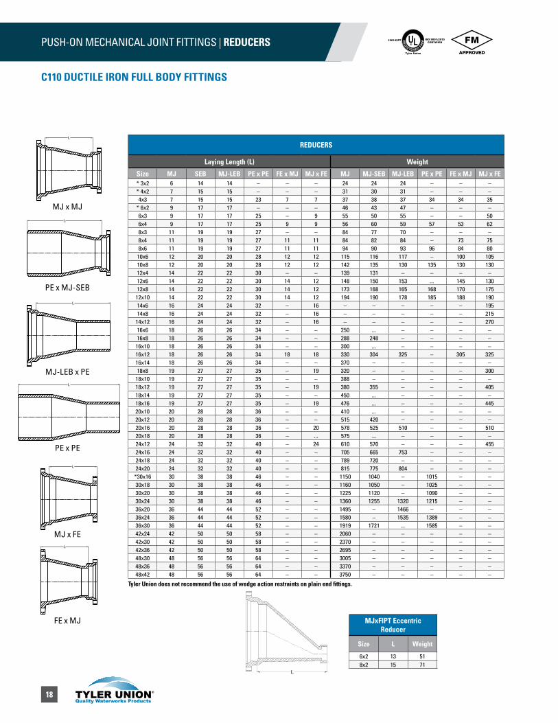
REDUCERS
Laying Length (L) Weight
Size MJ SEB MJ-LEB PE x PE FE x MJ MJ x FE MJ MJ-SEB MJ-LEB PE x PE FE x MJ MJ x FE* 3x2 6 14 14 – – – 24 24 24 – – –* 4x2 7 15 15 – – – 31 30 31 – – –4x3 7 15 15 23 7 7 37 38 37 34 34 35
* 6x2 9 17 17 – – – 46 43 47 – – –6x3 9 17 17 25 – 9 55 50 55 – – 506x4 9 17 17 25 9 9 56 60 59 57 53 628x3 11 19 19 27 – – 84 77 70 – – –8x4 11 19 19 27 11 11 84 82 84 – 73 758x6 11 19 19 27 11 11 94 90 93 96 84 80
10x6 12 20 20 28 12 12 115 116 117 – 100 10510x8 12 20 20 28 12 12 142 135 130 135 130 13012x4 14 22 22 30 – – 139 131 – – – –12x6 14 22 22 30 14 12 148 150 153 ... 145 13012x8 14 22 22 30 14 12 173 168 165 168 170 175
12x10 14 22 22 30 14 12 194 190 178 185 188 19014x6 16 24 24 32 – 16 – – – – – 19514x8 16 24 24 32 – 16 – – – – – 215
14x12 16 24 24 32 – 16 – – – – – 27016x6 18 26 26 34 – – 250 ... – – – –16x8 18 26 26 34 – – 288 248 – – – –
16x10 18 26 26 34 – – 300 ... – – – –16x12 18 26 26 34 18 18 330 304 325 – 305 32516x14 18 26 26 34 – – 370 – – – – –18x8 19 27 27 35 – 19 320 – – – – 300
18x10 19 27 27 35 – – 388 – – – – –18x12 19 27 27 35 – 19 380 355 – – – 40518x14 19 27 27 35 – – 450 ... – – – –18x16 19 27 27 35 – 19 476 ... – – – 44520x10 20 28 28 36 – – 410 ... – – – –20x12 20 28 28 36 – – 515 420 – – – –20x16 20 28 28 36 – 20 578 525 510 – – 51020x18 20 28 28 36 – ... 575 ... – – – –24x12 24 32 32 40 – 24 610 570 – – – 45524x16 24 32 32 40 – – 705 665 753 – – –24x18 24 32 32 40 – – 789 720 – – – –24x20 24 32 32 40 – – 815 775 804 – – –
*30x16 30 38 38 46 – – 1150 1040 – 1015 – –30x18 30 38 38 46 – – 1160 1050 – 1025 – –30x20 30 38 38 46 – – 1225 1120 – 1090 – –30x24 30 38 38 46 – – 1360 1255 1320 1215 – –36x20 36 44 44 52 – – 1495 – 1466 – – –36x24 36 44 44 52 – – 1580 – 1535 1389 – –36x30 36 44 44 52 – – 1919 1721 ... 1585 – –42x24 42 50 50 58 – – 2060 – – – – –42x30 42 50 50 58 – – 2370 – – – – –42x36 42 50 50 58 – – 2695 – – – – –48x30 48 56 56 64 – – 3005 – – – – –48x36 48 56 56 64 – – 3370 – – – – –48x42 48 56 56 64 – – 3750 – – – – –
L
L
L
L
L
L
MJxFIPT Eccentric Reducer
Size L Weight
6x2 13 518x2 15 71
L
C110 DUCTILE IRON FULL BODY FITTINGS
MJ x MJ
PE x MJ-SEB
MJ-LEB x PE
PE x PE
MJ x FE
FE x MJ
Tyler Union does not recommend the use of wedge action restraints on plain end fittings.

19
PUSH-ON MECHANICAL JOINT FITTINGS | SOLID SLEEVES
C110 DUCTILE IRON FULL BODY FITTINGS
UL®
RE
GISTERED FIR
M
ISO 9001:2015CERTIFIED
10014257
Tyler Union
SOLID SLEEVES
Size Pipe O.D. L1 Weight L2 Weight
*2 2.50 8.00 13 12.00 183 4.00 7.50 25 12.00 364 4.80 7.50 35 12.00 476 6.90 7.50 45 12.00 658 9.10 7.50 65 12.00 9010 11.10 7.50 85 12.00 10812 13.20 7.50 120 12.00 13616 17.40 9.50 206 15.00 28918 19.50 9.50 246 15.00 28220 21.60 9.50 275 15.00 33624 25.80 9.50 360 15.00 45930 32.00 15.00 745 24.00 122036 38.30 15.00 1047 24.00 150242 44.50 15.00 1312 24.00 155048 50.80 15.00 1585 24.00 1940
ADAPTERS MJ x FE
Size L Weight3 8.00 304 8.00 426 8.00 578 8.00 88
10 8.00 12012 8.00 15016 8.00 25718 8.00 30420 8.00 37224 8.00 48830 10.00 68236 10.00 1070
* MJ x PE DUAL-PURPOSE CUTTING-IN SLEEVE
Size For use on pipe OD L L1 D Gland
onlyGland and
sleeve4 4.80–5.00 12.00 8.00 4.80 6.0 726 6.90–7.10 12.00 8.00 6.90 10.0 948 9.05–9.30 12.00 8.00 9.05 16.0 12210 11.10–11.40 12.00 8.00 11.10 25.0 17512 13.20–13.50 12.00 8.00 13.20 30.0 235
*DUAL PURPOSE SLEEVE
Size Pipe O.D. L1 Weight L2 Weight4 4.80/5.00 7.50 33 12.00 446 6.90/7.10 7.50 46 12.00 678 9.05/9.30 7.50 65 12.00 88
10 11.10/11.40 – – 12.00 111†12 13.20/13.50 – – 12.00 221†16 17.40/17.80 – – 15.00 385
All sizes use MJ Dual purpose Gland.* Not included in AWWA C110.† 12” and 16” are sold assembled.NOTE: Sizes 4”–10” Use standard MJ Gasket; 12” and 16” require special gaskets.
L1 L2
D
L1 L
L
Tyler Union does not recommend the use of wedge action restraints on plain end fittings.

20
PUSH-ON MECHANICAL JOINT FITTINGS | PLUGS / CAPS / ADAPTER UL®
RE
GISTERED FIR
M
ISO 9001:2015CERTIFIED
10014257
Tyler Union
C110 DUCTILE IRON FULL BODY FITTINGS
PLUGS
Size Weight*2 53 94 136 158 45
10 6612 7914 12016 147
†18 192†20 220†24 338†30 660†36 838†42 1180†48 1455
CAPS
Size Weight*2 63 104 186 348 46
10 5812 8616 178
†18 215†20 250†24 370†30 680†36 850†42 1180†48 1595
2”–16” 18”–48” 2”–16” 18”–48”
SWIVEL x SOLID ADAPTER
Size X Laying Lenght
Pipe O.D. L
4 X 13 0.52 426 X12 0.55 616 X 18 0.55 896 X 24 0.55 1086 X 36 0.55 1568 X 13 0.60 97
12 X 13 0.75 164
TYTON® PLUG** SOLID OR TAPPED
Size Tap T Weight**4 2 0.60 186 2 0.65 258 2 0.70 4610 2 0.75 7012 2 0.75 95
PUSH-IN PLUG WITH EARS
Size Tap Weight14 2 10116 2 13718 2 177†20 2 239†24 2 311
T
† Dished* Not included in AWWA C110.Note: Optional 2” tap in the center.
Weights do not include accessories.** Not included in AWWA C110.TYTON is a registered trademarkof U.S Pipe and Foundry company.
† Dished — Not flat as shown.NOTE: To be used with all push in pipe and fittings.NOTE: Blocking still required ears for assembly only.
† Dished* Not included in AWWA C110.Note: Optional 2” tap in the center.
Weights with Gland.
21
PUSH-ON MECHANICAL JOINT FITTINGS | WYES / LATERALS / GLANDS / KITS & WEIGHTS
C110 DUCTILE IRON FULL BODY FITTINGS
UL®
RE
GISTERED FIR
M
ISO 9001:2015CERTIFIED
10014257
Tyler Union
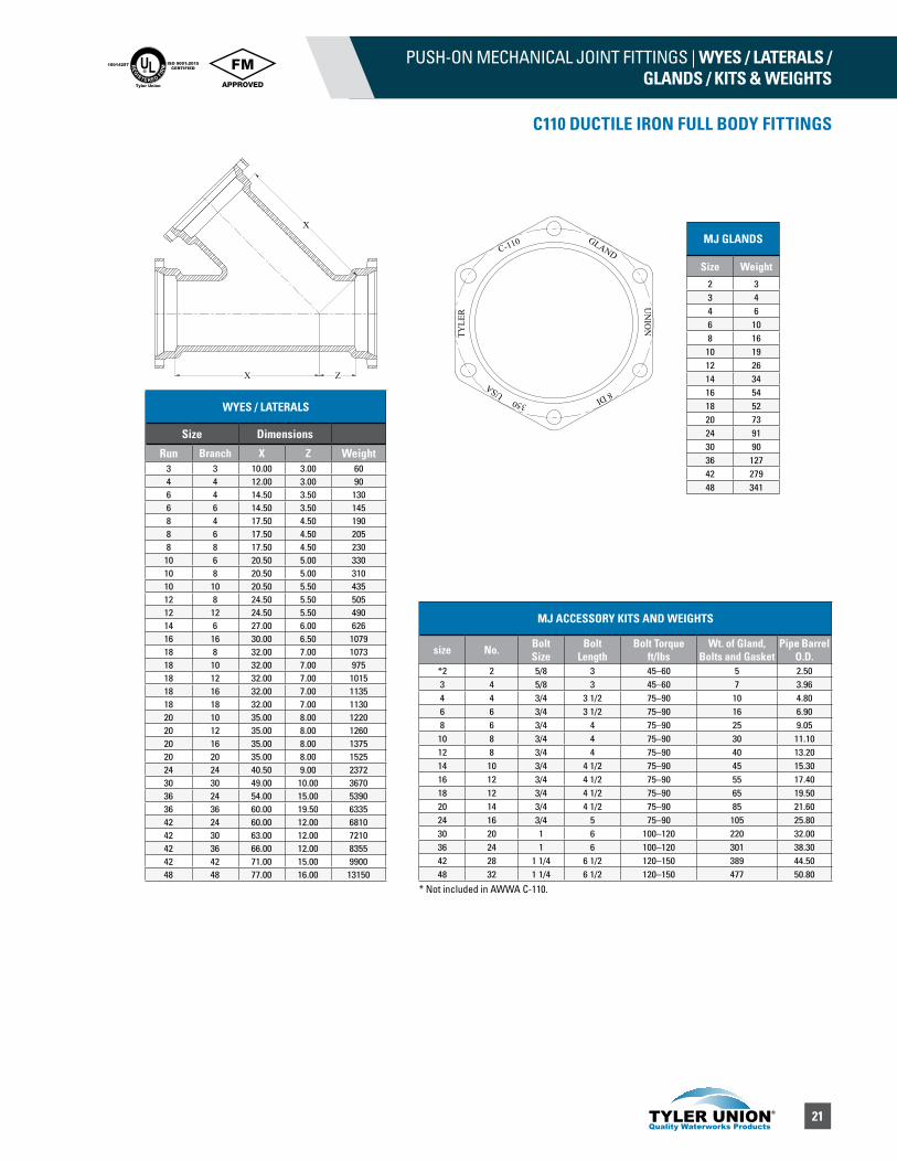
WYES / LATERALS
Size Dimensions
Run Branch X Z Weight3 3 10.00 3.00 604 4 12.00 3.00 906 4 14.50 3.50 1306 6 14.50 3.50 1458 4 17.50 4.50 1908 6 17.50 4.50 2058 8 17.50 4.50 230
10 6 20.50 5.00 33010 8 20.50 5.00 31010 10 20.50 5.50 43512 8 24.50 5.50 50512 12 24.50 5.50 49014 6 27.00 6.00 62616 16 30.00 6.50 107918 8 32.00 7.00 107318 10 32.00 7.00 97518 12 32.00 7.00 101518 16 32.00 7.00 113518 18 32.00 7.00 113020 10 35.00 8.00 122020 12 35.00 8.00 126020 16 35.00 8.00 137520 20 35.00 8.00 152524 24 40.50 9.00 237230 30 49.00 10.00 367036 24 54.00 15.00 539036 36 60.00 19.50 633542 24 60.00 12.00 681042 30 63.00 12.00 721042 36 66.00 12.00 835542 42 71.00 15.00 990048 48 77.00 16.00 13150
X Z
X
MJ GLANDS
Size Weight2 33 44 66 108 16
10 1912 2614 3416 5418 5220 7324 9130 9036 12742 27948 341
C-110
TYLE
R
GLANDU
NIO
N
8 DIUSA
350
MJ ACCESSORY KITS AND WEIGHTS
size No. Bolt Size
Bolt Length
Bolt Torque ft/lbs
Wt. of Gland, Bolts and Gasket
Pipe Barrel O.D.
*2 2 5/8 3 45–60 5 2.503 4 5/8 3 45–60 7 3.964 4 3/4 3 1/2 75–90 10 4.806 6 3/4 3 1/2 75–90 16 6.908 6 3/4 4 75–90 25 9.0510 8 3/4 4 75–90 30 11.1012 8 3/4 4 75–90 40 13.2014 10 3/4 4 1/2 75–90 45 15.3016 12 3/4 4 1/2 75–90 55 17.4018 12 3/4 4 1/2 75–90 65 19.5020 14 3/4 4 1/2 75–90 85 21.6024 16 3/4 5 75–90 105 25.8030 20 1 6 100–120 220 32.0036 24 1 6 100–120 301 38.3042 28 1 1/4 6 1/2 120–150 389 44.5048 32 1 1/4 6 1/2 120–150 477 50.80
* Not included in AWWA C-110.
22
UNION-TITE FITTINGS UL®
RE
GISTERED FIR
M
ISO 9001:2015CERTIFIED
10014257
Tyler Union
C153 DUCTILE IRON COMPACT FITTINGS
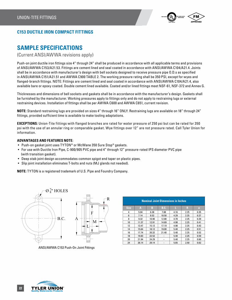
SAMPLE SPECIFICATIONS (Current ANSI/AWWA revisions apply)
Push-on joint ductile iron fittings size 4” through 24” shall be produced in accordance with all applicable terms and provisions of ANSI/AWWA C153/A21.53. Fittings are cement lined and seal coated in accordance with ANSI/AWWA C104/A21.4. Joints shall be in accordance with manufacturer’s design with bell sockets designed to receive pressure pipe O.D.s as specified in ANSI/AWWA C151/A21.51 and AWWA C900 TABLE 2. The working pressure rating shall be 350 PSI, except for wyes and flanged-branch fittings. NOTE: Fittings are cement lined and seal coated in accordance with ANSI/AWWA C104/A21.4, also available bare or epoxy coated. Double cement lined available. Coated and/or lined fittings meet NSF-61, NSF-372 and Annex G.
Thicknesses and dimensions of bell sockets and gaskets shall be in accordance with the manufacturer’s design. Gaskets shall be furnished by the manufacturer. Working pressures apply to fittings only and do not apply to restraining lugs or external restraining devices. Installation of fittings shall be per AWWA C600 and AWWA C651, current revision.
NOTE: Standard restraining lugs are provided on sizes 4” through 16” ONLY. Restraining lugs are available on 18” through 24” fittings, provided sufficient time is available to make tooling adaptations.
EXCEPTIONS: Union-Tite fit tings with flanged branches are rated for water pressure of 250 psi but can be rated for 350 psi with the use of an annular ring or comparable gasket. Wye fit tings over 12” are not pressure rated. Call Tyler Union for information.
ADVANTAGES AND FEATURES NOTE: • Push-on gasket joint uses TYTON® or McWane 350 Sure Stop® gaskets. • For use with Ductile Iron Pipe, C-900/905 PVC pipe and 4” through 12” pressure-rated IPS diameter PVC pipe (with transition gasket). • Deep stab joint design accommodates common spigot end taper on plastic pipes. • Slip joint installation eliminates T-bolts and nuts (MJ glands not needed).
NOTE: TYTON is a registered trademark of U.S. Pipe and Foundry Company.
Nominal Joint Dimensions in Inches
Size A B B.C. L R ø4 5.04 6.38 7.88 4.16 2.25 0.356 7.14 8.52 10.50 4.29 2.25 0.378 9.32 10.90 12.88 4.78 2.25 0.3910 11.37 12.91 14.69 4.98 2.25 0.4112 13.47 15.12 17.19 4.98 2.25 0.4314 15.64 18.12 19.00 5.40 2.25 0.5116 17.74 20.32 21.40 5.40 2.25 0.5218 19.83 22.52 – 5.40 2.25 0.5920 21.94 24.29 – 5.40 2.25 0.6024 26.14 29.14 – 5.65 2.50 0.62
R
LM
AB.C.
Ø 78" HOLES
F
ANSI/AWWA C153 Push-On Joint Fittings
23
UNION-TITE FITTINGS | BENDSUL®
RE
GISTERED FIR
M
ISO 9001:2015CERTIFIED
10014257
Tyler Union
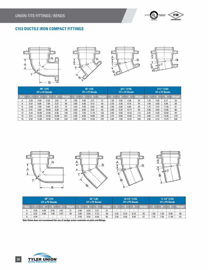
C153 DUCTILE IRON COMPACT FITTINGS
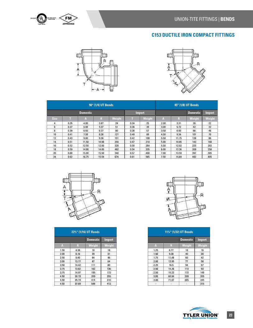
90° (1/4) UT Bends 45° (1/8) UT Bends
Domestic Import Domestic Import
Size T A R Weight T Weight A R Weight Weight4 0.35 4.00 3.87 24 0.34 25 2.00 3.31 26 226 0.37 5.00 5.37 51 0.36 39 3.00 5.72 42 328 0.39 6.50 6.37 80 0.38 57 3.50 6.93 66 46
10 0.41 7.50 8.36 121 0.40 89 4.50 9.34 101 7012 0.43 9.00 9.36 151 0.42 108 5.50 11.75 128 8614 0.51 11.50 10.98 254 0.47 210 5.00 10.85 143 16016 0.52 12.50 12.00 328 0.50 264 5.50 12.02 225 20218 0.59 14.00 14.00 482 0.54 335 6.00 12.36 209 25020 0.60 15.00 15.50 340 0.57 400 7.00 13.59 397 30524 0.62 16.75 15.59 674 0.61 565 7.50 14.69 492 405
22½° (1/16) UT Bends
Domestic Import
A R Weight Weight1.50 4.38 18 182.00 8.16 39 312.50 9.40 64 463.00 13.17 67 643.50 14.42 111 803.75 13.82 162 1363.75 14.97 195 1724.50 30.19 209 2554.50 35.19 414 3104.50 37.69 596 412
11¼° (1/32) UT Bends
Domestic Import
A R Weight Weight1.25 6.77 18 161.50 9.38 40 301.75 11.48 60 422.00 13.95 77 582.25 16.5 94 672.50 14.26 113 932.50 15.23 172 1483.00 60.94 209 2053.00 71.07 265 245
– – – 315
24
UNION-TITE FITTINGS / BENDS UL®
RE
GISTERED FIR
M
ISO 9001:2015CERTIFIED
10014257
Tyler Union
C153 DUCTILE IRON COMPACT FITTINGS
90° (1/4) UT x FE Bends
Size T A B R Weight4 0.35 4.50 6.50 3.87 316 0.37 6.00 7.00 5.37 498 0.39 7.00 9.00 6.37 74
10 0.41 9.00 10.00 8.36 13012 0.43 10.00 12.00 9.36 15814 0.51 12.00 15.50 10.98 23116 0.52 13.00 16.50 12.00 233
90° (1/4) UT x PE Bends
Size T A B R Weight4 0.35 4.50 6.50 3.87 316 0.37 6.00 7.00 5.37 498 0.39 – – – –
45° (1/8) UT x FE Bends
A B R Weight2.00 4.00 3.31 213.00 5.00 5.72 423.50 5.50 6.93 604.50 6.50 9.34 935.50 7.50 11.75 1225.50 8.50 10.85 1626.00 9.50 12.02 275
45° (1/8) UT x PE Bends
A B R Weight2.00 8.00 3.31 213.00 9.00 5.72 383.50 9.50 6.93 60
22½° (1/16) UT x FE Bends
A B R Weight1.50 3.50 4.38 252.25 4.30 8.16 442.50 4.50 9.40 643.00 5.30 13.17 903.50 5.50 14.42 1123.75 6.80 13.82 1744.00 7.50 14.97 228
22 1/2° (1/16) UT x PE Bends
A B R Weight– – – –
2.25 8.10 8.16 352.50 8.30 9.40 57
11¼° (1/32) UT x FE Bends
A B R Weight1.25 3.30 6.77 241.50 3.50 9.38 301.75 3.75 11.48 612.00 4.00 13.95 802.25 4.30 16.50 942.60 5.75 14.26 1702.60 6.10 15.23 228
11 1/4° (1/32) UT x PE Bends
A B R Weight– – – –
1.50 7.30 9.38 361.75 7.55 11.48 55
Tyler Union does not recommend the use of wedge action restraints on plain end fittings.
25
UNION-TITE FITTINGS | TEESUL®
RE
GISTERED FIR
M
ISO 9001:2015CERTIFIED
10014257
Tyler Union
C153 DUCTILE IRON COMPACT FITTINGS
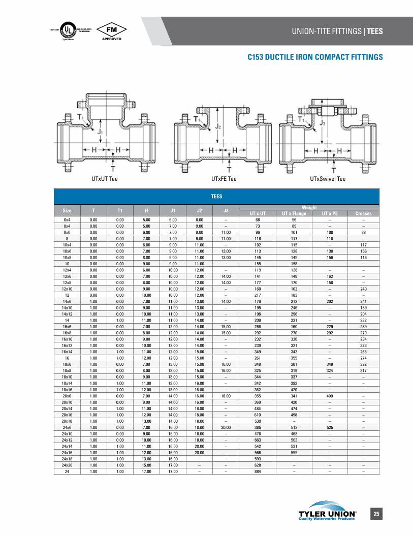
TEES
Size T T1 H J1 J2 J3 WeightUT x UT UT x Flange UT x PE Crosses
6x4 0.00 0.00 5.00 6.00 8.00 – 68 56 – –8x4 0.00 0.00 5.00 7.00 9.00 – 73 89 – –8x6 0.00 0.00 6.00 7.00 9.00 11.00 96 101 100 888 0.00 0.00 7.00 7.00 9.00 11.00 116 117 110 –
10x4 0.00 0.00 6.00 9.00 11.00 – 102 115 – 11710x6 0.00 0.00 7.00 9.00 11.00 13.00 113 128 130 15610x8 0.00 0.00 8.00 9.00 11.00 13.00 145 145 156 11610 0.00 0.00 9.00 9.00 11.00 – 155 158 – –
12x4 0.00 0.00 6.00 10.00 12.00 – 119 138 – –12x6 0.00 0.00 7.00 10.00 12.00 14.00 141 148 162 –12x8 0.00 0.00 8.00 10.00 12.00 14.00 177 170 158 –
12x10 0.00 0.00 9.00 10.00 12.00 – 160 162 – 24012 0.00 0.00 10.00 10.00 12.00 – 217 183 – –
14x6 1.00 0.00 7.00 11.00 13.00 14.00 176 212 202 24114x10 1.00 0.00 9.00 11.00 13.00 – 195 246 – 18914x12 1.00 0.00 10.00 11.00 13.00 – 196 296 – 204
14 1.00 1.00 11.00 11.00 14.00 – 209 321 – 22216x6 1.00 0.00 7.00 12.00 14.00 15.00 266 160 229 23916x8 1.00 0.00 8.00 12.00 14.00 15.00 292 270 292 270
16x10 1.00 0.00 9.00 12.00 14.00 – 232 330 – 23416x12 1.00 0.00 10.00 12.00 14.00 – 239 321 – 32316x14 1.00 1.00 11.00 12.00 15.00 – 349 342 – 268
16 1.00 1.00 12.00 12.00 15.00 – 261 355 – 27418x6 1.00 0.00 7.00 13.00 15.00 16.00 348 301 348 32218x8 1.00 0.00 8.00 13.00 15.00 16.00 325 319 324 317
18x10 1.00 0.00 9.00 13.00 15.00 – 344 337 – –18x14 1.00 1.00 11.00 13.00 16.00 – 342 393 – –18x16 1.00 1.00 12.00 13.00 16.00 – 362 420 – –20x6 1.00 0.00 7.00 14.00 16.00 18.00 355 341 400 –
20x10 1.00 0.00 9.00 14.00 16.00 – 369 420 – –20x14 1.00 1.00 11.00 14.00 18.00 – 484 474 – –20x16 1.00 1.00 12.00 14.00 18.00 – 610 498 – –20x18 1.00 1.00 13.00 14.00 18.00 – 539 – – –24x6 1.00 0.00 7.00 16.00 18.00 20.00 385 512 525 –
24x10 1.00 0.00 9.00 16.00 18.00 – 478 468 – –24x12 1.00 0.00 10.00 16.00 18.00 – 663 503 – –24x14 1.00 1.00 11.00 16.00 20.00 – 542 531 – –24x16 1.00 1.00 12.00 16.00 20.00 – 566 555 – –24x18 1.00 1.00 13.00 16.00 – – 593 – – –24x20 1.00 1.00 15.00 17.00 – – 628 – – –
24 1.00 1.00 17.00 17.00 – – 884 – – –
UTxUT Tee UTxFE Tee UTxSwivel Tee

26
UNION-TITE FITTINGS | TEES / WYES UL®
RE
GISTERED FIR
M
ISO 9001:2015CERTIFIED
10014257
Tyler Union
C153 DUCTILE IRON COMPACT FITTINGS
WYES
UT X UT X PE TEES
Size
Run Branch T T1 H J3 Weight6 6 0.37 0.37 6.00 11.50 608 6 0.39 37.00 6.00 12.50 8012 6 0.43 0.37 7.00 15.50 140
TAPPED TEES / CROSSES
Size A B C D4 0.35 3.00 6.00 27.006 0.37 3.50 6.00 38.008 0.39 3.50 6.00 59.0010 0.41 3.50 6.00 72.0012 0.43 3.50 6.00 92.00
UT WYE
Size T T1 P N Weight8x4 0.39 0.35 13.50 0.00 8910x4 0.41 0.35 15.00 0.00 14110x6 0.41 0.37 16.00 1.00 15110x8 0.41 0.39 17.00 2.50 175
10 0.41 0.41 18.00 4.00 20012x4 0.43 0.35 16.50 0.00 17812x6 0.43 0.37 18.50 1.50 20112x8 0.43 0.39 18.50 1.50 22412x10 0.43 0.41 20.00 3.00 240
12 0.43 0.43 20.00 5.00 28914x6 0.51 0.44 19.50 0.00 23614x8 0.51 0.45 21.00 1.50 25514x10 0.51 0.46 22.50 3.00 325
14 0.51 0.51 25.00 6.00 47516x6 0.52 0.45 21.00 0.00 28116x8 0.52 0.46 22.50 0.50 30416x12 0.52 0.48 25.00 3.50 346
16 0.52 0.52 28.00 6.50 380
Tyler Union does not recommend the use of wedge action restraints on plain end fittings.
27
UNION-TITE FITTINGS | REDUCERS / CAPS & PLUGS / ADAPTERSUL®
RE
GISTERED FIR
M
ISO 9001:2015CERTIFIED
10014257
Tyler Union
C153 DUCTILE IRON COMPACT FITTINGS
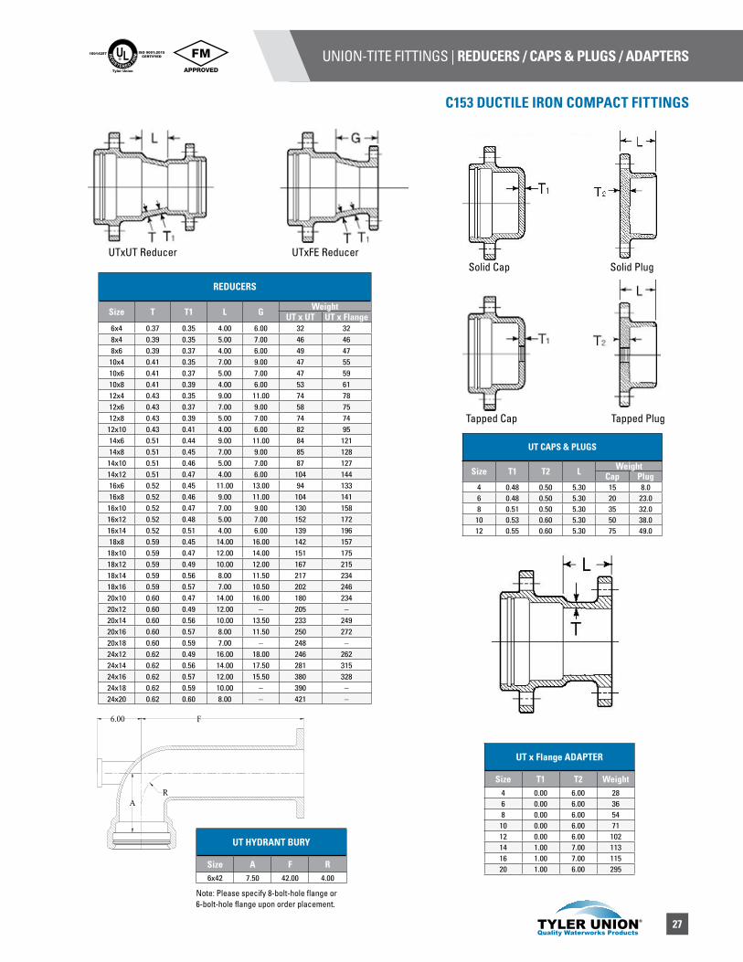
REDUCERS
Size T T1 L G WeightUT x UT UT x Flange
6x4 0.37 0.35 4.00 6.00 32 328x4 0.39 0.35 5.00 7.00 46 468x6 0.39 0.37 4.00 6.00 49 47
10x4 0.41 0.35 7.00 9.00 47 5510x6 0.41 0.37 5.00 7.00 47 5910x8 0.41 0.39 4.00 6.00 53 6112x4 0.43 0.35 9.00 11.00 74 7812x6 0.43 0.37 7.00 9.00 58 7512x8 0.43 0.39 5.00 7.00 74 74
12x10 0.43 0.41 4.00 6.00 82 9514x6 0.51 0.44 9.00 11.00 84 12114x8 0.51 0.45 7.00 9.00 85 128
14x10 0.51 0.46 5.00 7.00 87 12714x12 0.51 0.47 4.00 6.00 104 14416x6 0.52 0.45 11.00 13.00 94 13316x8 0.52 0.46 9.00 11.00 104 141
16x10 0.52 0.47 7.00 9.00 130 15816x12 0.52 0.48 5.00 7.00 152 17216x14 0.52 0.51 4.00 6.00 139 19618x8 0.59 0.45 14.00 16.00 142 157
18x10 0.59 0.47 12.00 14.00 151 17518x12 0.59 0.49 10.00 12.00 167 21518x14 0.59 0.56 8.00 11.50 217 23418x16 0.59 0.57 7.00 10.50 202 24620x10 0.60 0.47 14.00 16.00 180 23420x12 0.60 0.49 12.00 – 205 –20x14 0.60 0.56 10.00 13.50 233 24920x16 0.60 0.57 8.00 11.50 250 27220x18 0.60 0.59 7.00 – 248 –24x12 0.62 0.49 16.00 18.00 246 26224x14 0.62 0.56 14.00 17.50 281 31524x16 0.62 0.57 12.00 15.50 380 32824x18 0.62 0.59 10.00 – 390 –24x20 0.62 0.60 8.00 – 421 –
UT CAPS & PLUGS
Size T1 T2 L WeightCap Plug
4 0.48 0.50 5.30 15 8.06 0.48 0.50 5.30 20 23.08 0.51 0.50 5.30 35 32.0
10 0.53 0.60 5.30 50 38.012 0.55 0.60 5.30 75 49.0
UTxFE Reducer UTxUT Reducer
Solid Cap Solid Plug
Tapped Cap Tapped Plug
UT HYDRANT BURY
Size A F R6x42 7.50 42.00 4.00
A
F6.00
R
UT x Flange ADAPTER
Size T1 T2 Weight4 0.00 6.00 286 0.00 6.00 368 0.00 6.00 5410 0.00 6.00 7112 0.00 6.00 10214 1.00 7.00 11316 1.00 7.00 11520 1.00 6.00 295
Note: Please specify 8-bolt-hole flange or 6-bolt-hole flange upon order placement.
28
CLASS 125 FLANGE IRON FITTINGS UL®
RE
GISTERED FIR
M
ISO 9001:2015CERTIFIED
10014257
Tyler Union
C110 DUCTILE IRON FULL BODY FITTINGS
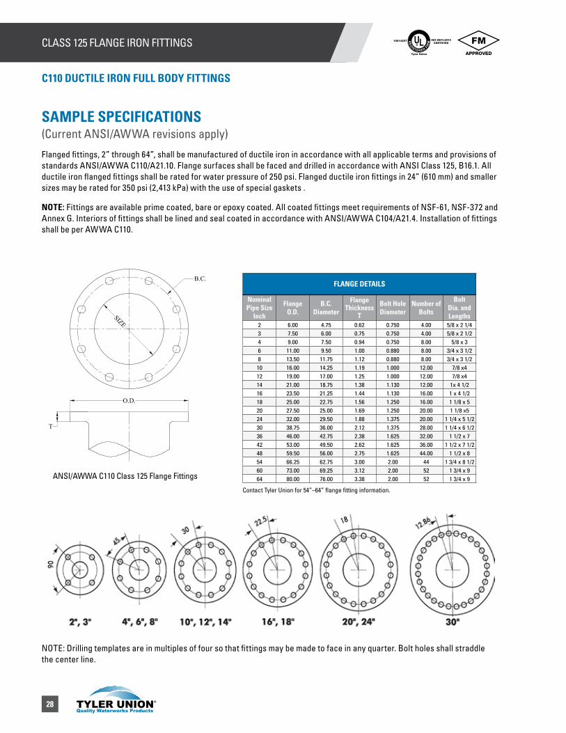
SAMPLE SPECIFICATIONS (Current ANSI/AWWA revisions apply)
Flanged fittings, 2” through 64”, shall be manufactured of ductile iron in accordance with all applicable terms and provisions of standards ANSI/AWWA C110/A21.10. Flange surfaces shall be faced and drilled in accordance with ANSI Class 125, B16.1. All ductile iron flanged fittings shall be rated for water pressure of 250 psi. Flanged ductile iron fittings in 24” (610 mm) and smaller sizes may be rated for 350 psi (2,413 kPa) with the use of special gaskets .
NOTE: Fittings are available prime coated, bare or epoxy coated. All coated fittings meet requirements of NSF-61, NSF-372 and Annex G. Interiors of fittings shall be lined and seal coated in accordance with ANSI/AWWA C104/A21.4. Installation of fittings shall be per AWWA C110.
FLANGE DETAILS
Nominal Pipe Size
Inch
Flange O.D.
B.C. Diameter
Flange Thickness
T
Bolt Hole Diameter
Number of Bolts
Bolt Dia. and Lengths
2 6.00 4.75 0.62 0.750 4.00 5/8 x 2 1/43 7.50 6.00 0.75 0.750 4.00 5/8 x 2 1/24 9.00 7.50 0.94 0.750 8.00 5/8 x 3 6 11.00 9.50 1.00 0.880 8.00 3/4 x 3 1/28 13.50 11.75 1.12 0.880 8.00 3/4 x 3 1/210 16.00 14.25 1.19 1.000 12.00 7/8 x412 19.00 17.00 1.25 1.000 12.00 7/8 x414 21.00 18.75 1.38 1.130 12.00 1x 4 1/216 23.50 21.25 1.44 1.130 16.00 1 x 4 1/218 25.00 22.75 1.56 1.250 16.00 1 1/8 x 520 27.50 25.00 1.69 1.250 20.00 1 1/8 x524 32.00 29.50 1.88 1.375 20.00 1 1/4 x 5 1/230 38.75 36.00 2.12 1.375 28.00 1 1/4 x 6 1/236 46.00 42.75 2.38 1.625 32.00 1 1/2 x 742 53.00 49.50 2.62 1.625 36.00 1 1/2 x 7 1/248 59.50 56.00 2.75 1.625 44.00 1 1/2 x 854 66.25 62.75 3.00 2.00 44 1 3/4 x 8 1/260 73.00 69.25 3.12 2.00 52 1 3/4 x 964 80.00 76.00 3.38 2.00 52 1 3/4 x 9
T
B.C.
SIZE
O.D.
ANSI/AWWA C110 Class 125 Flange Fittings
Contact Tyler Union for 54”–64” flange fitting information.
NOTE: Drilling templates are in multiples of four so that fittings may be made to face in any quarter. Bolt holes shall straddle the center line.
29
CLASS 125 FLANGE IRON FITTINGS | BENDSUL®
RE
GISTERED FIR
M
ISO 9001:2015CERTIFIED
10014257
Tyler Union
C110 DUCTILE IRON FULL BODY FITTINGS
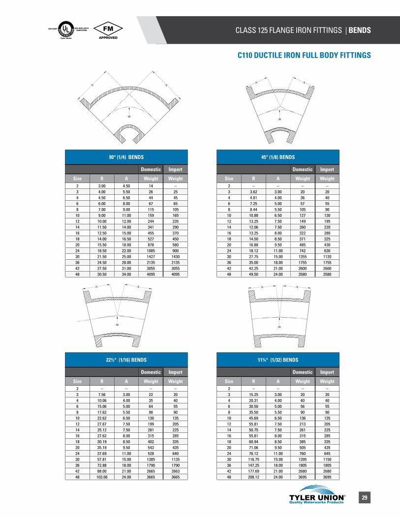
90° (1/4) BENDS
Domestic Import
Size R A Weight Weight2 3.00 4.50 14 –3 4.00 5.50 26 254 4.50 6.50 44 456 6.00 8.00 67 658 7.00 9.00 115 10510 9.00 11.00 159 16512 10.00 12.00 244 23514 11.50 14.00 341 29016 12.50 15.00 455 37018 14.00 16.50 527 45020 15.50 18.00 878 58024 18.50 22.00 1085 90030 21.50 25.00 1427 143036 24.50 28.00 2135 213542 27.50 31.00 3055 305548 30.50 34.00 4095 4095
45° (1/8) BENDS
Domestic Import
Size R A Weight Weight2 – – – –3 3.62 3.00 20 204 4.81 4.00 36 406 7.25 5.00 57 558 8.44 5.50 105 90
10 10.88 6.50 127 13012 13.25 7.50 149 19514 12.06 7.50 260 22016 13.25 8.00 322 28018 14.50 8.50 371 32520 16.88 9.50 485 43024 18.12 11.00 742 63030 27.75 15.00 1355 112036 35.00 18.00 1755 175542 42.25 21.00 2600 260048 49.50 24.00 3580 3580
22½° (1/16) BENDS
Domestic Import
Size R A Weight Weight2 – – – –3 7.56 3.00 22 204 10.06 4.00 35 406 15.06 5.00 64 558 17.62 5.50 90 90
10 22.62 6.50 130 13512 27.67 7.50 199 20514 25.12 7.50 281 22516 27.62 8.00 315 28518 30.19 8.50 402 33520 35.19 9.50 543 43524 37.69 11.00 528 64030 57.81 15.00 1385 113536 72.88 18.00 1790 179042 88.00 21.00 2665 266348 103.06 24.00 3665 3665
11¼° (1/32) BENDS
Domestic Import
Size R A Weight Weight2 – – – –3 15.25 3.00 20 204 20.31 4.00 40 406 30.50 5.00 56 558 35.50 5.50 90 9010 45.69 6.50 136 13512 55.81 7.50 213 20514 50.75 7.50 261 22516 55.81 8.00 315 28518 60.94 8.50 385 33520 71.06 9.50 505 43524 76.12 11.00 760 64530 116.75 15.00 1395 115036 147.25 18.00 1805 180542 177.69 21.00 2680 268048 208.12 24.00 3695 3695
AA
R
A A
R
A A
R
A
R
AA A
R
A
R
A
30
CLASS 125 FLANGE IRON FITTINGS | BENDS UL®
RE
GISTERED FIR
M
ISO 9001:2015CERTIFIED
10014257
Tyler Union
C110 DUCTILE IRON FULL BODY FITTINGS
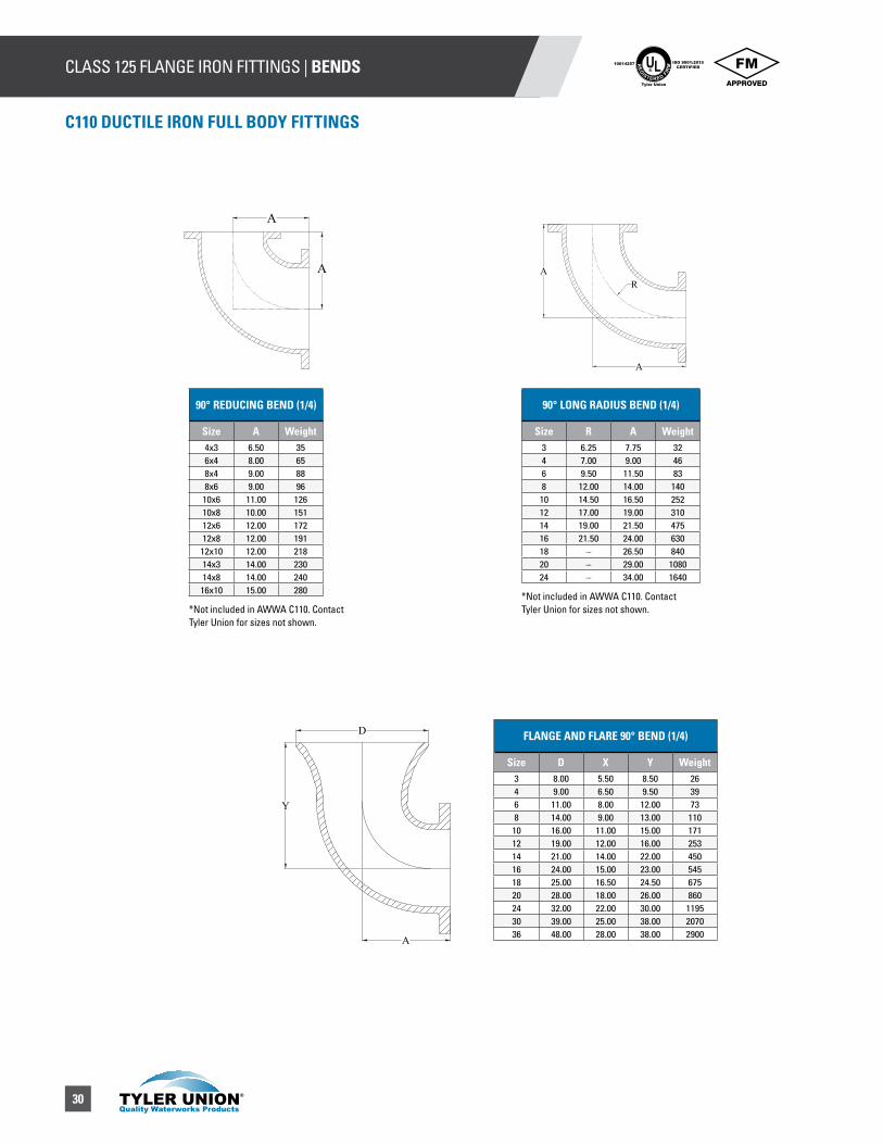
90° LONG RADIUS BEND (1/4)
Size R A Weight3 6.25 7.75 324 7.00 9.00 466 9.50 11.50 838 12.00 14.00 140
10 14.50 16.50 25212 17.00 19.00 31014 19.00 21.50 47516 21.50 24.00 63018 – 26.50 84020 – 29.00 108024 – 34.00 1640
FLANGE AND FLARE 90° BEND (1/4)
Size D X Y Weight3 8.00 5.50 8.50 264 9.00 6.50 9.50 396 11.00 8.00 12.00 738 14.00 9.00 13.00 11010 16.00 11.00 15.00 17112 19.00 12.00 16.00 25314 21.00 14.00 22.00 45016 24.00 15.00 23.00 54518 25.00 16.50 24.50 67520 28.00 18.00 26.00 86024 32.00 22.00 30.00 119530 39.00 25.00 38.00 207036 48.00 28.00 38.00 2900
90° REDUCING BEND (1/4)
Size A Weight4x3 6.50 356x4 8.00 658x4 9.00 888x6 9.00 9610x6 11.00 12610x8 10.00 15112x6 12.00 17212x8 12.00 19112x10 12.00 21814x3 14.00 23014x8 14.00 24016x10 15.00 280
*Not included in AWWA C110. Contact Tyler Union for sizes not shown.
*Not included in AWWA C110. Contact Tyler Union for sizes not shown.
A
A
A
AR
A
Y
D
31
CLASS 125 FLANGE IRON FITTINGS | BENDSUL®
RE
GISTERED FIR
M
ISO 9001:2015CERTIFIED
10014257
Tyler Union
C110 DUCTILE IRON FULL BODY FITTINGS
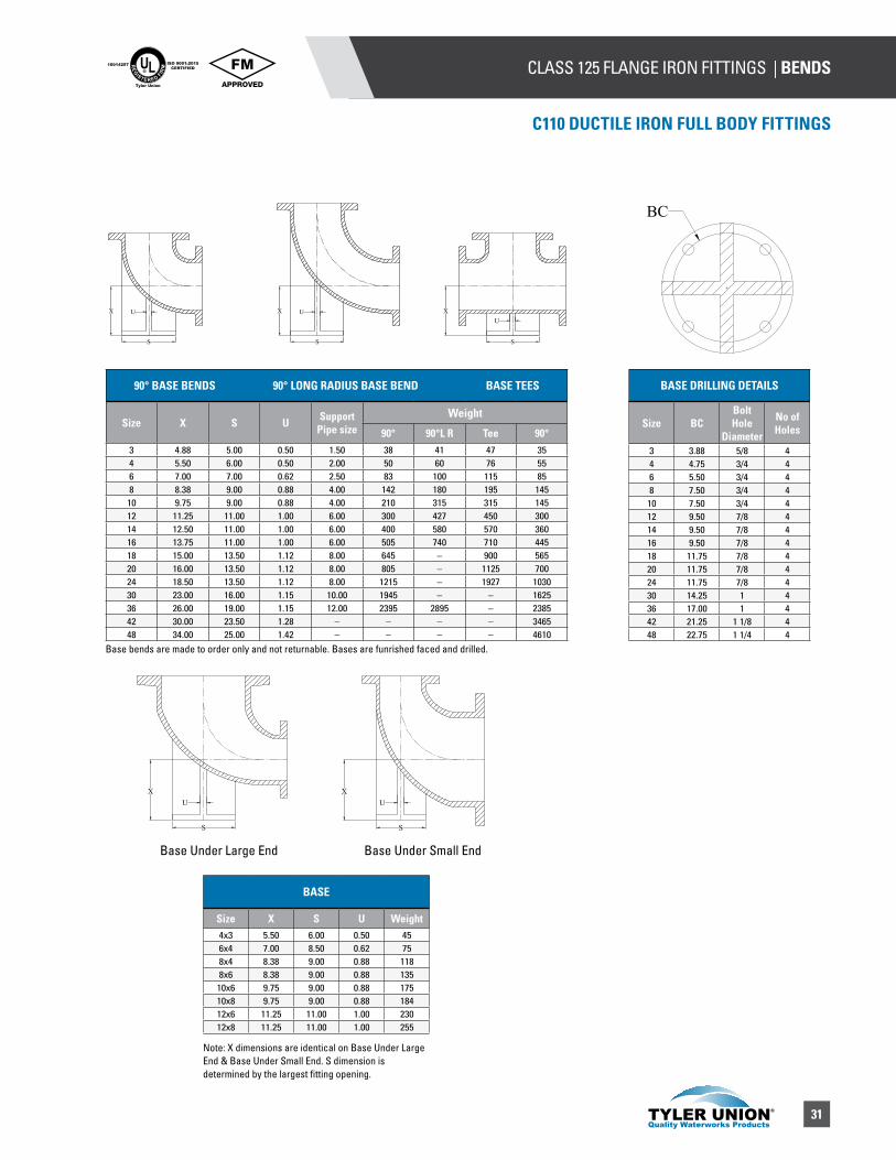
BASE DRILLING DETAILS
Size BCBolt Hole
Diameter
No of Holes
3 3.88 5/8 44 4.75 3/4 46 5.50 3/4 48 7.50 3/4 4
10 7.50 3/4 412 9.50 7/8 414 9.50 7/8 416 9.50 7/8 418 11.75 7/8 420 11.75 7/8 424 11.75 7/8 430 14.25 1 436 17.00 1 442 21.25 1 1/8 448 22.75 1 1/4 4
BASE
Size X S U Weight4x3 5.50 6.00 0.50 456x4 7.00 8.50 0.62 758x4 8.38 9.00 0.88 1188x6 8.38 9.00 0.88 13510x6 9.75 9.00 0.88 17510x8 9.75 9.00 0.88 18412x6 11.25 11.00 1.00 23012x8 11.25 11.00 1.00 255
Base bends are made to order only and not returnable. Bases are funrished faced and drilled.
90° BASE BENDS 90° LONG RADIUS BASE BEND BASE TEES
Size X S U Support Pipe size
Weight
90° 90°L R Tee 90°3 4.88 5.00 0.50 1.50 38 41 47 354 5.50 6.00 0.50 2.00 50 60 76 556 7.00 7.00 0.62 2.50 83 100 115 858 8.38 9.00 0.88 4.00 142 180 195 14510 9.75 9.00 0.88 4.00 210 315 315 14512 11.25 11.00 1.00 6.00 300 427 450 30014 12.50 11.00 1.00 6.00 400 580 570 36016 13.75 11.00 1.00 6.00 505 740 710 44518 15.00 13.50 1.12 8.00 645 – 900 56520 16.00 13.50 1.12 8.00 805 – 1125 70024 18.50 13.50 1.12 8.00 1215 – 1927 103030 23.00 16.00 1.15 10.00 1945 – – 162536 26.00 19.00 1.15 12.00 2395 2895 – 238542 30.00 23.50 1.28 – – – – 346548 34.00 25.00 1.42 – – – – 4610
X U
S
X U
S
XU
S
BC
XU
S
XU
S
Note: X dimensions are identical on Base Under Large End & Base Under Small End. S dimension is determined by the largest fitting opening.
Base Under Large End Base Under Small End
32
CLASS 125 FLANGE IRON FITTINGS | TEES UL®
RE
GISTERED FIR
M
ISO 9001:2015CERTIFIED
10014257
Tyler Union
C110 DUCTILE IRON FULL BODY FITTINGS
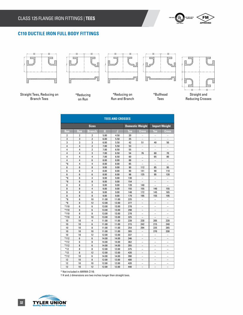
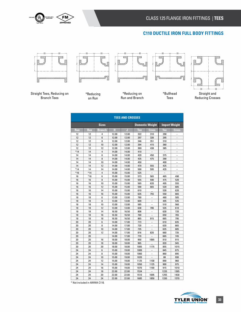
TEES AND CROSSES
Sizes Domestic Weight Import Weight
Run Run Branch H J Tee Cross Tee Cross2 2 2 5.00 4.50 20 – – –3 3 2 6.00 5.50 35 – – –3 3 3 6.00 5.50 42 51 40 504 4 2 7.00 5.50 53 – – –4 4 2 7.00 6.50 55 – – –4 4 3 7.00 6.50 54 76 60 704 4 4 7.00 6.50 60 _ 65 804 4 6 8.00 8.00 88 – – –
*6 4 4 8.00 8.00 85 – – –6 6 8 9.00 9.00 90 112 85 956 6 4 8.00 8.00 90 141 90 1106 6 6 8.00 8.00 98 125 95 120
*8 6 4 9.00 9.00 130 – – –*8 6 8 9.00 9.00 154 – – –8 8 3 9.00 9.00 128 140 – –8 8 4 9.00 9.00 155 155 140 1558 8 6 9.00 9.00 148 172 145 1658 8 8 9.00 9.00 179 195 155 195
*8 8 10 11.00 11.00 225 – – –*8 8 12 12.00 12.00 277 – – –
*†10 6 6 13.00 13.00 278 – – –*†10 8 6 13.00 13.00 298 – – –*†10 8 8 13.00 13.00 278 – – –*†10 8 10 13.00 13.00 325 – – –10 10 4 11.00 11.00 239 220 205 22010 10 6 11.00 11.00 215 242 215 24010 10 8 11.00 11.00 254 294 225 26510 10 10 11.00 11.00 265 – 270 33010 10 12 12.00 12.00 337 – – –
*†12 6 6 14.00 14.00 346 – – –*†12 6 8 14.00 14.00 362 – – –*†12 8 6 14.00 14.00 355 – – –*12 8 8 12.00 12.00 375 – – –*12 8 12 12.00 12.00 420 – – –
*†12 10 6 14.00 14.00 390 – – –12 10 8 12.00 12.00 400 – – –12 10 10 12.00 12.00 420 – – –12 10 12 12.00 12.00 440 – – –
Straight Tees, Reducing on Branch Tees
*Reducingon Run
*Reducing onRun and Branch
*Bullhead Tees
Straight and Reducing Crosses
HH
J
J
H H
J
H H
J
H H
J
H H
J
* Not included in AWWA C110.† H and J dimensions are two inches longer than straight tees.
33
CLASS 125 FLANGE IRON FITTINGS | TEESUL®
RE
GISTERED FIR
M
ISO 9001:2015CERTIFIED
10014257
Tyler Union
C110 DUCTILE IRON FULL BODY FITTINGS
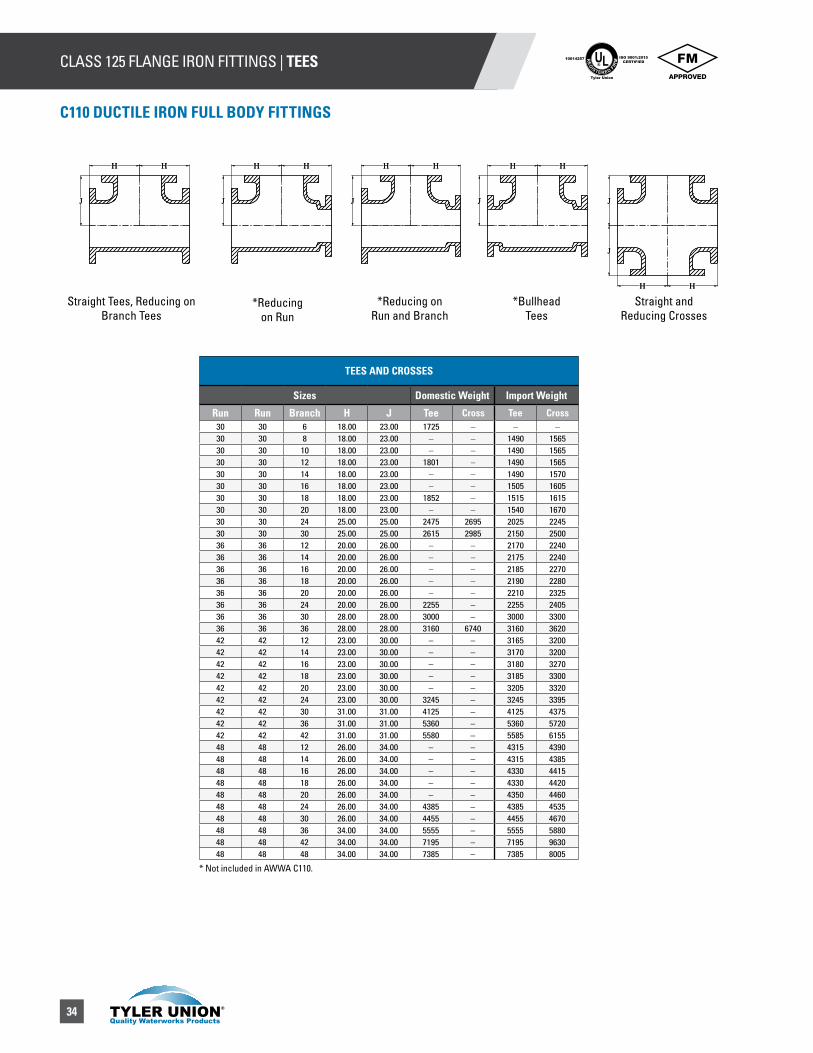
TEES AND CROSSES
Sizes Domestic Weight Import Weight
Run Run Branch H J Tee Cross Tee Cross12 12 4 12.00 12.00 322 310 290 –12 12 6 12.00 12.00 297 326 295 –12 12 8 12.00 12.00 346 351 310 –12 12 10 12.00 12.00 394 415 360 –12 12 12 12.00 12.00 369 438 385 –
*14 14 4 14.00 14.00 410 – – –14 14 6 14.00 14.00 420 450 375 –14 14 8 14.00 14.00 435 475 390 –14 14 10 14.00 14.00 450 400 –14 14 12 14.00 14.00 470 555 425 –
*14 14 14 14.00 14.00 500 595 435 –*16 *14 4 15.00 15.00 525 – – –16 *16 6 15.00 15.00 573 565 465 49016 16 8 15.00 15.00 555 590 475 52016 16 10 15.00 15.00 565 620 495 55516 16 12 15.00 15.00 590 665 520 60516 16 14 15.00 15.00 610 _ 530 62016 16 16 15.00 15.00 635 755 550 66518 18 6 13.00 13.00 780 – 480 50518 18 8 13.00 13.00 609 – 495 53518 18 10 13.00 13.00 585 – 510 56018 18 12 13.00 13.00 638 706 535 61018 18 14 16.50 16.50 808 – 630 72018 18 16 16.50 16.50 760 – 650 76518 18 18 16.50 16.50 865 915 665 79520 20 6 14.00 17.00 773 – 610 63520 20 8 14.00 17.00 720 – 620 66520 20 10 14.00 17.00 735 – 635 68520 20 12 14.00 17.00 816 820 660 73520 20 14.00 17.00 770 – 665 74520 20 16 18.00 18.00 950 1065 810 91520 20 18 18.00 18.00 965 _ 820 94520 20 20 18.00 18.00 1005 1175 855 101524 24 6 15.00 19.00 1089 – 845 87524 24 8 15.00 19.00 1060 – 860 89524 24 10 15.00 19.00 1020 – 88 93024 24 12 15.00 19.00 1125 1100 890 96024 24 14 15.00 19.00 1050 1125 900 97524 24 16 15.00 19.00 1070 1160 915 101024 24 18 22.00 22.00 1534 – 1220 136524 24 20 22.00 22.00 1510 1695 1255 143024 24 24 22.00 22.00 1685 1850 1330 1570
Straight Tees, Reducing on Branch Tees
*Reducingon Run
*Reducing onRun and Branch
*Bullhead Tees
Straight and Reducing Crosses
HH
J
J
H H
J
H H
J
H H
J
H H
J
* Not included in AWWA C110.
34
CLASS 125 FLANGE IRON FITTINGS | TEES UL®
RE
GISTERED FIR
M
ISO 9001:2015CERTIFIED
10014257
Tyler Union
C110 DUCTILE IRON FULL BODY FITTINGS
TEES AND CROSSES
Sizes Domestic Weight Import Weight
Run Run Branch H J Tee Cross Tee Cross30 30 6 18.00 23.00 1725 – – –30 30 8 18.00 23.00 – – 1490 156530 30 10 18.00 23.00 – – 1490 156530 30 12 18.00 23.00 1801 – 1490 156530 30 14 18.00 23.00 – – 1490 157030 30 16 18.00 23.00 – – 1505 160530 30 18 18.00 23.00 1852 – 1515 161530 30 20 18.00 23.00 – – 1540 167030 30 24 25.00 25.00 2475 2695 2025 224530 30 30 25.00 25.00 2615 2985 2150 250036 36 12 20.00 26.00 – – 2170 224036 36 14 20.00 26.00 – – 2175 224036 36 16 20.00 26.00 – – 2185 227036 36 18 20.00 26.00 – – 2190 228036 36 20 20.00 26.00 – – 2210 232536 36 24 20.00 26.00 2255 – 2255 240536 36 30 28.00 28.00 3000 – 3000 330036 36 36 28.00 28.00 3160 6740 3160 362042 42 12 23.00 30.00 – – 3165 320042 42 14 23.00 30.00 – – 3170 320042 42 16 23.00 30.00 – – 3180 327042 42 18 23.00 30.00 – – 3185 330042 42 20 23.00 30.00 – – 3205 332042 42 24 23.00 30.00 3245 – 3245 339542 42 30 31.00 31.00 4125 – 4125 437542 42 36 31.00 31.00 5360 – 5360 572042 42 42 31.00 31.00 5580 – 5585 615548 48 12 26.00 34.00 – – 4315 439048 48 14 26.00 34.00 – – 4315 438548 48 16 26.00 34.00 – – 4330 441548 48 18 26.00 34.00 – – 4330 442048 48 20 26.00 34.00 – – 4350 446048 48 24 26.00 34.00 4385 – 4385 453548 48 30 26.00 34.00 4455 – 4455 467048 48 36 34.00 34.00 5555 – 5555 588048 48 42 34.00 34.00 7195 – 7195 963048 48 48 34.00 34.00 7385 – 7385 8005
Straight Tees, Reducing on Branch Tees
*Reducingon Run
*Reducing onRun and Branch
*Bullhead Tees
Straight and Reducing Crosses
HH
J
J
H H
J
H H
J
H H
J
H H
J
HH
J
J
H H
J
H H
J
H H
J
H H
J
* Not included in AWWA C110.

35
CLASS 125 FLANGE IRON FITTINGS | REDUCERSUL®
RE
GISTERED FIR
M
ISO 9001:2015CERTIFIED
10014257
Tyler Union
C110 DUCTILE IRON FULL BODY FITTINGS
CONCENTRIC REDUCER
Domestic Import
D D1 L Weight Weight3.00 2.00 6.00 17 –4.00 2.00 7.00 23 –4.00 3.00 7.00 29 306.00 2.00 9.00 30 –6.00 3.00 9.00 44 406.00 4.00 9.00 46 456.00 5.00 9.00 56 –8.00 3.00 11.00 61 658.00 4.00 11.00 63 –8.00 5.00 11.00 70 –8.00 6.00 11.00 75 75
10.00 4.00 12.00 98 8510.00 6.00 12.00 107 9010.00 8.00 12.00 116 11012.00 4.00 14.00 119 12012.00 6.00 14.00 130 13012.00 8.00 14.00 152 14512.00 10.00 14.00 178 17014.00 6.00 16.00 165 15514.00 8.00 16.00 185 17514.00 10.00 16.00 205 19014.00 12.00 16.00 235 22016.00 6.00 18.00 210 19016.00 8.00 18.00 230 21016.00 10.00 18.00 255 23516.00 12.00 18.00 285 26516.00 14.00 18.00 315 28018.00 8.00 19.00 265 24018.00 10.00 19.00 290 26518.00 12.00 19.00 320 29518.00 14.00 19.00 350 31018.00 16.00 19.00 405 34020.00 10.00 20.00 418 –20.00 12.00 20.00 465 34520.00 14.00 20.00 430 35520.00 16.00 20.00 445 39020.00 18.00 20.00 470 41024.00 12.00 24.00 608 48024.00 14.00 24.00 565 49024.00 16.00 24.00 610 52524.00 18.00 24.00 645 55024.00 20.00 24.00 695 59030.00 16.00 30.00 945 –30.00 18.00 30.00 970 81030.00 20.00 30.00 1144 87030.00 24.00 30.00 1155 97036.00 20.00 36.00 – 123036.00 24.00 36.00 – 134536.00 30.00 36.00 – 155542.00 24.00 42.00 1810 182042.00 30.00 42.00 2060 206042.00 36.00 42.00 – 234548.00 30.00 48.00 2615 262548.00 36.00 48.00 2940 295048.00 42.00 48.00 3320 3320
*ECCENTRIC REDUCER
Domestic Import
D D1 L Weight Weight4.00 3.00 7.00 30 –6.00 3.00 9.00 45 –6.00 4.00 9.00 52 458.00 4.00 11.00 70 –8.00 6.00 11.00 80 –10.00 4.00 12.00 95 –10.00 6.00 12.00 98 –10.00 8.00 12.00 123 –12.00 4.00 14.00 120 –12.00 6.00 14.00 135 –12.00 8.00 14.00 149 –12.00 10.00 14.00 177 –14.00 6.00 16.00 165 –14.00 8.00 16.00 185 –14.00 10.00 16.00 205 –14.00 12.00 16.00 294 –16.00 6.00 18.00 210 –16.00 8.00 18.00 230 –16.00 10.00 18.00 255 –16.00 12.00 18.00 285 –16.00 14.00 18.00 315 –18.00 8.00 19.00 265 –18.00 10.00 19.00 290 –18.00 12.00 19.00 306 –18.00 14.00 19.00 350 –18.00 16.00 19.00 385 –20.00 10.00 20.00 350 –20.00 12.00 20.00 370 –20.00 14.00 20.00 402 –20.00 16.00 20.00 449 –20.00 18.00 20.00 455 –24.00 12.00 24.00 535 –24.00 14.00 24.00 570 –24.00 16.00 24.00 614 –24.00 18.00 24.00 645 –24.00 20.00 24.00 695 –30.00 16.00 30.00 778 –30.00 18.00 30.00 810 –30.00 20.00 30.00 870 –30.00 24.00 30.00 970 –36.00 24.00 36.00 1425 –36.00 30.00 36.00 2120 –42.00 24.00 42.00 2340 –42.00 30.00 42.00 2060 –42.00 36.00 42.00 2345 –48.00 30.00 48.00 2625 –48.00 36.00 48.00 2950 –48.00 42.00 48.00 3320 –
L
D D1
L
D
D1
Eccentric Reducer
Concentric Reducer
*Eccentric Reducers not included in AWWA C110.
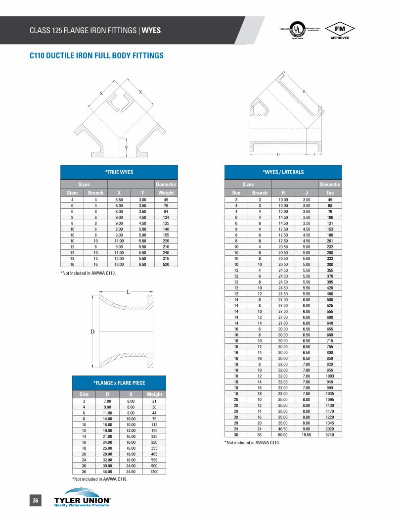
36
CLASS 125 FLANGE IRON FITTINGS | WYES UL®
RE
GISTERED FIR
M
ISO 9001:2015CERTIFIED
10014257
Tyler Union
C110 DUCTILE IRON FULL BODY FITTINGS
*WYES / LATERALS
Sizes Domestic
Run Branch H J Tee 3 3 10.00 3.00 494 3 12.00 3.00 684 4 12.00 3.00 766 4 14.50 3.50 1066 6 14.50 3.50 1318 4 17.50 4.50 1538 6 17.50 4.50 1888 8 17.50 4.50 201
10 4 20.50 5.00 23210 6 20.50 5.00 28810 8 20.50 5.00 33310 10 20.50 5.00 30012 4 24.50 5.50 35512 6 24.50 5.50 37012 8 24.50 5.50 39512 10 24.50 5.50 42012 12 24.50 5.50 46014 6 27.00 6.00 50014 8 27.00 6.00 52514 10 27.00 6.00 55514 12 27.00 6.00 60014 14 27.00 6.00 64016 6 30.00 6.50 65516 8 30.00 6.50 68016 10 30.00 6.50 71516 12 30.00 6.50 75516 14 30.00 6.50 80016 16 30.00 6.50 85018 8 32.00 7.00 82018 10 32.00 7.00 85518 12 32.00 7.00 100318 14 32.00 7.00 94018 16 32.00 7.00 99018 18 32.00 7.00 103520 10 35.00 8.00 109520 12 35.00 8.00 113020 14 35.00 8.00 117020 16 35.00 8.00 122020 20 35.00 8.00 134524 24 40.50 9.00 202036 36 60.00 19.50 5740
*TRUE WYES
Sizes Domestic
Stem Branch X Y Weight4 4 6.50 3.00 496 4 8.00 3.50 756 6 8.00 3.50 848 6 9.00 4.50 1348 8 9.00 4.50 125
10 6 8.00 5.00 14010 8 9.00 5.00 15510 10 11.00 5.00 22012 8 9.00 5.50 21012 10 11.00 5.50 24012 12 12.00 5.50 31516 16 13.00 6.50 520
*FLANGE x FLARE PIECE
Size D X Weight3 7.00 8.00 214 9.00 8.00 306 11.00 8.00 448 14.00 10.00 75
10 16.00 10.00 11312 19.00 12.00 15514 21.00 16.00 22516 24.00 16.00 33018 25.00 16.00 35520 28.00 18.00 46524 32.00 18.00 59830 39.00 24.00 90036 46.00 24.00 1200
*Not included in AWWA C110.
*Not included in AWWA C110.
*Not included in AWWA C110.
H J
H
Y
XX
L
D
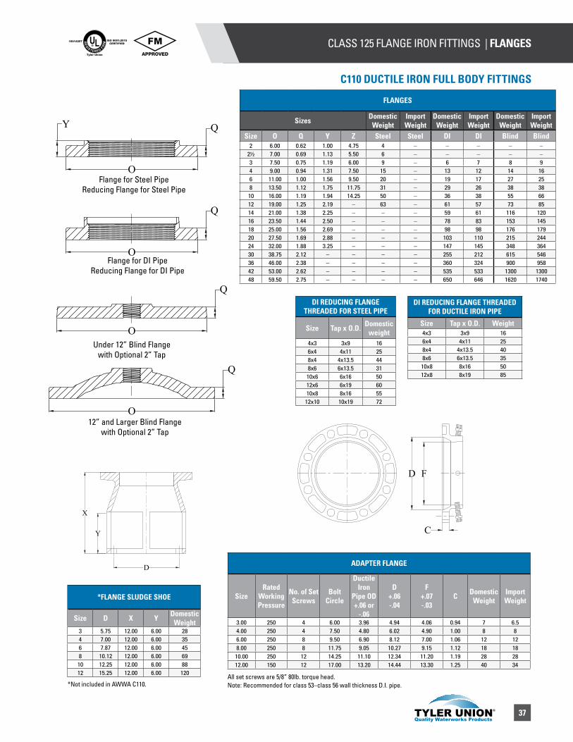
37
CLASS 125 FLANGE IRON FITTINGS | FLANGESUL®
RE
GISTERED FIR
M
ISO 9001:2015CERTIFIED
10014257
Tyler Union
C110 DUCTILE IRON FULL BODY FITTINGS
DI REDUCING FLANGE THREADED FOR STEEL PIPE
Size Tap x O.D. Domestic weight
4x3 3x9 166x4 4x11 258x4 4x13.5 448x6 6x13.5 31
10x6 6x16 5012x6 6x19 6010x8 8x16 55
12x10 10x19 72
ADAPTER FLANGE
SizeRated
Working Pressure
No. of Set Screws
Bolt Circle
Ductile Iron
Pipe OD+.06 or
-.06
D+.06-.04
F+.07-.03
C Domestic Weight
Import Weight
3.00 250 4 6.00 3.96 4.94 4.06 0.94 7 6.54.00 250 4 7.50 4.80 6.02 4.90 1.00 8 86.00 250 8 9.50 6.90 8.12 7.00 1.06 12 128.00 250 8 11.75 9.05 10.27 9.15 1.12 18 18
10.00 250 12 14.25 11.10 12.34 11.20 1.19 28 2812.00 150 12 17.00 13.20 14.44 13.30 1.25 40 34
*Not included in AWWA C110.All set screws are 5/8” 80lb. torque head.Note: Recommended for class 53–class 56 wall thickness D.I. pipe.
Y Q
O
Q
Q
Q
O
O
O
Flange for Steel PipeReducing Flange for Steel Pipe
Flange for DI PipeReducing Flange for DI Pipe
Under 12” Blind Flange with Optional 2” Tap
12” and Larger Blind Flange with Optional 2” Tap
DI REDUCING FLANGE THREADED FOR DUCTILE IRON PIPE
Size Tap x O.D. Weight4x3 3x9 166x4 4x11 258x4 4x13.5 408x6 6x13.5 3510x8 8x16 5012x8 8x19 85
*FLANGE SLUDGE SHOE
Size D X Y Domestic Weight
3 5.75 12.00 6.00 284 7.00 12.00 6.00 356 7.87 12.00 6.00 458 10.12 12.00 6.00 69
10 12.25 12.00 6.00 8812 15.25 12.00 6.00 120
X
Y
D
D F
C
FLANGES
Sizes Domestic Weight
Import Weight
Domestic Weight
Import Weight
Domestic Weight
Import Weight
Size O Q Y Z Steel Steel DI DI Blind Blind2 6.00 0.62 1.00 4.75 4 – – – – –
2½ 7.00 0.69 1.13 5.50 6 – – – – –3 7.50 0.75 1.19 6.00 9 – 6 7 8 94 9.00 0.94 1.31 7.50 15 – 13 12 14 166 11.00 1.00 1.56 9.50 20 – 19 17 27 258 13.50 1.12 1.75 11.75 31 – 29 26 38 3810 16.00 1.19 1.94 14.25 50 – 36 38 55 6612 19.00 1.25 2.19 – 63 – 61 57 73 8514 21.00 1.38 2.25 – – – 59 61 116 12016 23.50 1.44 2.50 – – – 78 83 153 14518 25.00 1.56 2.69 – – – 98 98 176 17920 27.50 1.69 2.88 – – – 103 110 215 24424 32.00 1.88 3.25 – – – 147 145 348 36430 38.75 2.12 – – – – 255 212 615 54636 46.00 2.38 – – – – 360 324 900 95842 53.00 2.62 – – – – 535 533 1300 130048 59.50 2.75 – – – – 650 646 1620 1740
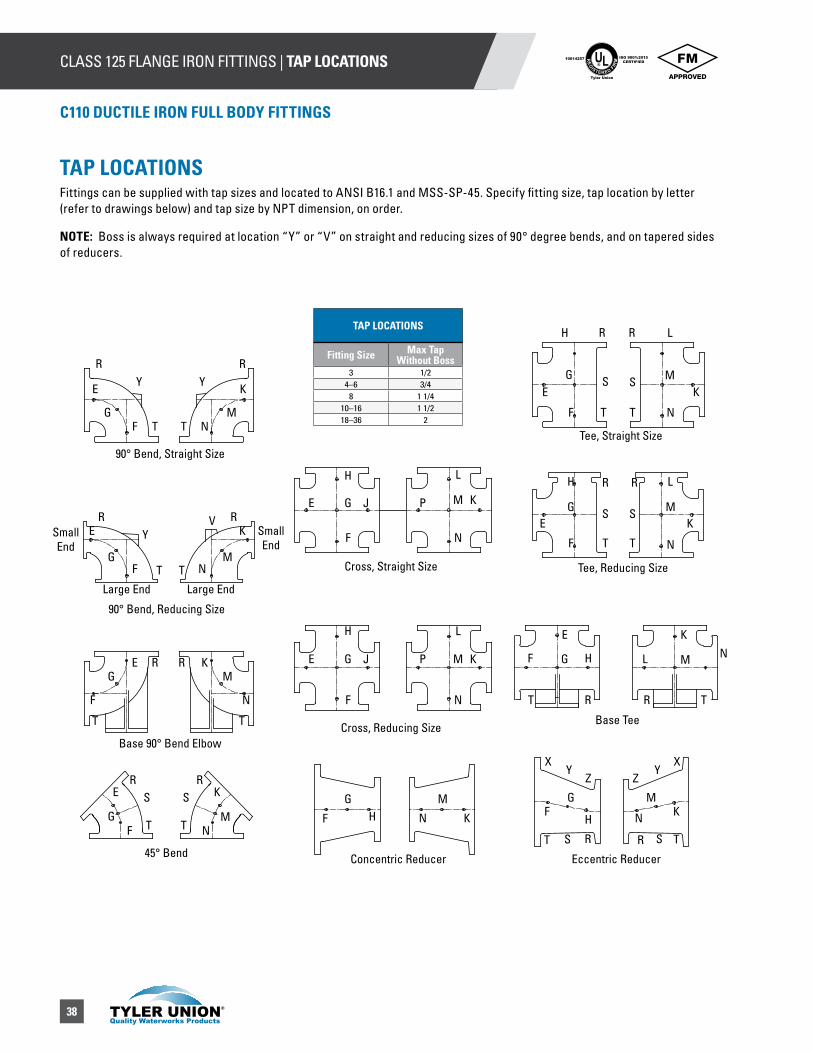
38
CLASS 125 FLANGE IRON FITTINGS | TAP LOCATIONS UL®
RE
GISTERED FIR
M
ISO 9001:2015CERTIFIED
10014257
Tyler Union
C110 DUCTILE IRON FULL BODY FITTINGS
90° Bend, Straight Size
90° Bend, Reducing Size
Base 90° Bend Elbow
45° Bend Concentric Reducer
Cross, Reducing SizeBase Tee
N
Eccentric Reducer
Tee, Reducing Size
Tee, Straight Size
Cross, Straight Size
Small End
Small End
Large End Large End
R
R R
R
R R
R R
R R
R R
R R
R R
Y Y
Y
Y Y
T T
T
T
T
T
T TT T
T T
T T
T T
E
E
E
E
E
E
E
E
E
G
G
G
G
G
M
G
G
G
G
G
F
F
F
F
F
F
F F
F
F
K
K
K
K
K
K
K
K
K
K
M
K
N
N
N
N
N
N
N N
N
N
X
M
M
M
M
M M
H
H
H
H
H
H
S S
S S
S S
L
L
L
L
L
J
J
P
P
S S
V
XZ Z
F M
H
G M
M
TAP LOCATIONSFittings can be supplied with tap sizes and located to ANSI B16.1 and MSS-SP-45. Specify fitting size, tap location by letter (refer to drawings below) and tap size by NPT dimension, on order.
NOTE: Boss is always required at location “Y” or “V” on straight and reducing sizes of 90° degree bends, and on tapered sides of reducers.
TAP LOCATIONS
Fitting Size Max Tap Without Boss
3 1/24–6 3/4
8 1 1/410–16 1 1/218–36 2
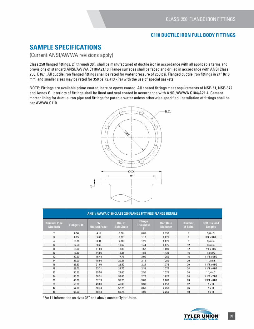
39
SAMPLE SPECIFICATIONS (Current ANSI/AWWA revisions apply)
Class 250 flanged fittings, 2” through 30”, shall be manufactured of ductile iron in accordance with all applicable terms and provisions of standard ANSI/AWWA C110/A21.10. Flange surfaces shall be faced and drilled in accordance with ANSI Class 250, B16.1. All ductile iron flanged fittings shall be rated for water pressure of 250 psi. Flanged ductile iron fittings in 24” (610 mm) and smaller sizes may be rated for 350 psi (2,413 kPa) with the use of special gaskets.
NOTE: Fittings are available prime coated, bare or epoxy coated. All coated fittings meet requirements of NSF-61, NSF-372 and Annex G. Interiors of fittings shall be lined and seal coated in accordance with ANSI/AWWA C104/A21.4. Cement mortar lining for ductile iron pipe and fittings for potable water unless otherwise specified. Installation of fittings shall be per AWWA C110.
ANSI / AWWA C110 CLASS 250 FLANGE FITTINGS FLANGE DETAILS
Nominal Pipe Size Inch Flange O.D. W
(Raised Face)Dia. of
Bolt Circle
Flange Thickness
T
Bolt Hole Diameter
Number of Bolts
Bolt Dia. and Lengths
2 6.50 4.19 5.00 0.88 0.750 8 5/8 x 3 3 8.25 5.69 6.62 1.12 0.875 8 3/4 x 31/24 10.00 6.94 7.88 1.25 0.875 8 3/4 x 46 12.50 9.69 10.62 1.44 0.875 12 3/4 x 48 15.00 11.94 13.00 1.62 1.000 12 7/8 x 41/210 17.50 14.06 15.25 1.88 1.125 16 1 x 51/212 20.50 16.44 17.75 2.00 1.250 16 1 1/8 x 51/214 23.00 18.94 20.25 2.12 1.250 20 1 1/8 x 616 25.50 21.06 22.50 2.25 1.375 20 1 1/4 x 61/218 28.00 23.31 24.75 2.38 1.375 24 1 1/4 x 61/220 30.50 25.56 27.00 2.50 1.375 24 1 1/4 x 724 36.00 30.31 32.00 2.75 1.625 24 1 1/2 x 71/230 43.00 37.19 39.25 3.00 2.000 28 1 3/4 x 81/236 50.00 43.69 46.00 3.38 2.250 32 2 x 1142 57.00 50.44 52.75 3.69 2.250 36 2 x 1148 65.00 58.44 60.75 4.00 2.250 40 2 x 11
CLASS 250 FLANGE IRON FITTINGS
C110 DUCTILE IRON FULL BODY FITTINGS
T
B.C.
SIZE
O.D.W
*For LL information on sizes 36” and above contact Tyler Union.
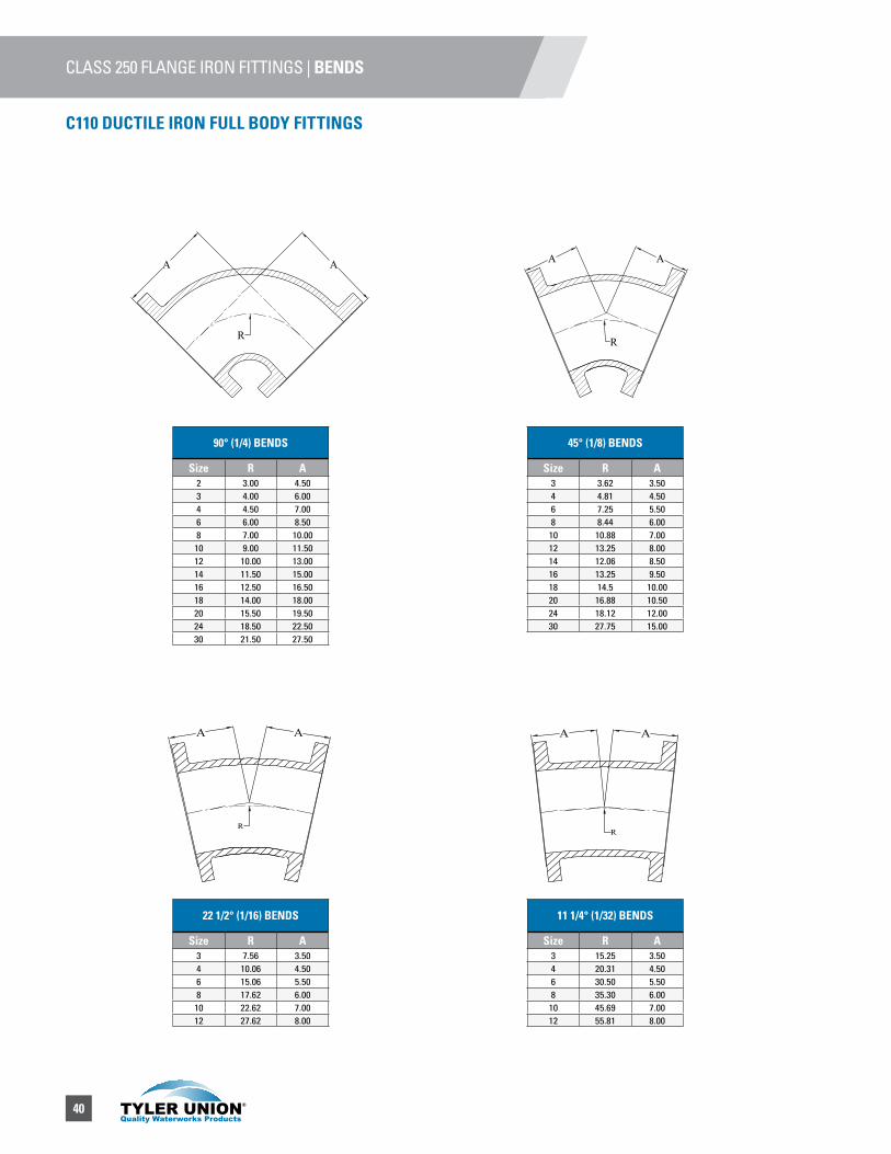
40
CLASS 250 FLANGE IRON FITTINGS | BENDS
90° (1/4) BENDS
Size R A2 3.00 4.503 4.00 6.004 4.50 7.006 6.00 8.508 7.00 10.00
10 9.00 11.5012 10.00 13.0014 11.50 15.0016 12.50 16.5018 14.00 18.0020 15.50 19.5024 18.50 22.5030 21.50 27.50
22 1/2° (1/16) BENDS
Size R A3 7.56 3.504 10.06 4.506 15.06 5.508 17.62 6.00
10 22.62 7.0012 27.62 8.00
11 1/4° (1/32) BENDS
Size R A3 15.25 3.504 20.31 4.506 30.50 5.508 35.30 6.00
10 45.69 7.0012 55.81 8.00
45° (1/8) BENDS
Size R A3 3.62 3.504 4.81 4.506 7.25 5.508 8.44 6.00
10 10.88 7.0012 13.25 8.0014 12.06 8.5016 13.25 9.5018 14.5 10.0020 16.88 10.5024 18.12 12.0030 27.75 15.00
A
R
A
R
A AA
R
A
R
A A
A A
R
A
R
AA A
R
A
R
A
C110 DUCTILE IRON FULL BODY FITTINGS

41
CLASS 250 FLANGE IRON FITTINGS | BENDS
*90° REDUCING BEND (1/4)
Size A Domestic Weight
4x3 6.50 356x4 8.00 –8x4 9.00 –8x6 9.00 –
10x6 11.00 –10x8 10.00 –12x6 12.00 –12x8 12.00 –
12x10 12.00 –14x3 14.00 –14x8 14.00 –
*90° REDUCING BEND (1/4)
Size R A Domestic Weight
3 6.25 7.75 324 7.00 9.00 –6 9.50 11.50 –8 14.00 14.00 –
10 16.50 16.50 –12 17.00 19.00 –14 19.00 21.50 –16 21.50 24.00 –18 – 26.50 –20 – 29.00 –24 – 34.00 –
BASE BENDS / LONG RADIUS BENDS / BASE TEES
Size X S U Support Pipe size
3 5.25 6.12 0.62 1.54 6.00 6.50 0.50 26 7.50 7.50 0.75 2.58 9.00 10.00 0.88 4
10 10.50 10.00 0.88 412 12.00 10.50 1.00 614 13.50 12.50 1.12 616 14.75 12.50 1.12 618 16.25 15.00 1.12 820 17.88 15.00 1.25 824 20.75 17.50 1.25 830 23.00 16.00 1.15 1036 26.00 19.00 1.15 10
BASE DRILLING DETAILS
Size BC Bolt Hole Diameter
No of Holes
3 4.50 7/8 44 5.00 3/4 46 5.88 7/8 48 7.88 7/8 4
10 7.88 7/8 412 10.62 7/8 414 10.62 7/8 416 10.62 7/8 418 13.00 7/8 420 13.00 7/8 424 15.25 1 1/8 4
C110 DUCTILE IRON FULL BODY FITTINGS
A A
AA
R
A A
AA
R
90° Base Bends 90° Long Radius Base Bends Base Tees
XU
S
X U
S
X U
S
BC
Base Bends are made to order only and not returnable. Bases are furnished faced and drilled.
*Not included in AWWA C110. *Not included in AWWA C110.
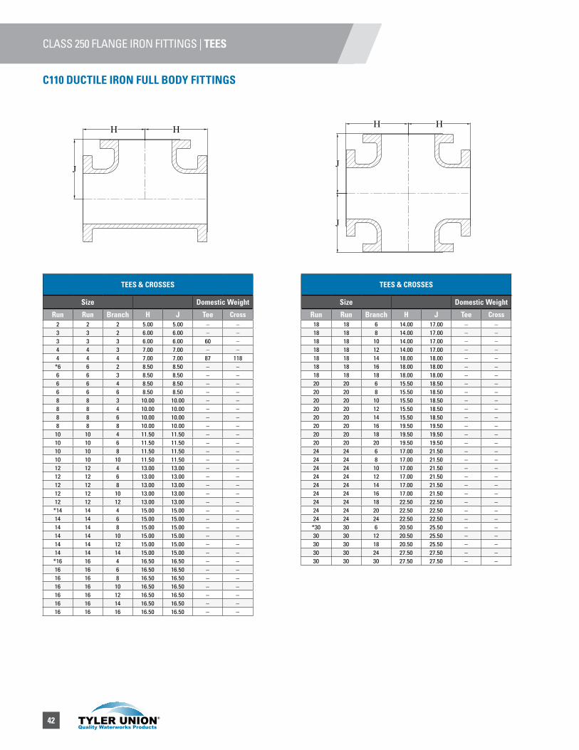
42
CLASS 250 FLANGE IRON FITTINGS | TEES
C110 DUCTILE IRON FULL BODY FITTINGS
TEES & CROSSES
Size Domestic Weight
Run Run Branch H J Tee Cross2 2 2 5.00 5.00 – –3 3 2 6.00 6.00 – –3 3 3 6.00 6.00 60 –4 4 3 7.00 7.00 – –4 4 4 7.00 7.00 87 118
*6 6 2 8.50 8.50 – –6 6 3 8.50 8.50 – –6 6 4 8.50 8.50 – –6 6 6 8.50 8.50 – –8 8 3 10.00 10.00 – –8 8 4 10.00 10.00 – –8 8 6 10.00 10.00 – –8 8 8 10.00 10.00 – –
10 10 4 11.50 11.50 – –10 10 6 11.50 11.50 – –10 10 8 11.50 11.50 – –10 10 10 11.50 11.50 – –12 12 4 13.00 13.00 – –12 12 6 13.00 13.00 – –12 12 8 13.00 13.00 – –12 12 10 13.00 13.00 – –12 12 12 13.00 13.00 – –
*14 14 4 15.00 15.00 – –14 14 6 15.00 15.00 – –14 14 8 15.00 15.00 – –14 14 10 15.00 15.00 – –14 14 12 15.00 15.00 – –14 14 14 15.00 15.00 – –
*16 16 4 16.50 16.50 – –16 16 6 16.50 16.50 – –16 16 8 16.50 16.50 – –16 16 10 16.50 16.50 – –16 16 12 16.50 16.50 – –16 16 14 16.50 16.50 – –16 16 16 16.50 16.50 – –
TEES & CROSSES
Size Domestic Weight
Run Run Branch H J Tee Cross18 18 6 14.00 17.00 – –18 18 8 14.00 17.00 – –18 18 10 14.00 17.00 – –18 18 12 14.00 17.00 – –18 18 14 18.00 18.00 – –18 18 16 18.00 18.00 – –18 18 18 18.00 18.00 – –20 20 6 15.50 18.50 – –20 20 8 15.50 18.50 – –20 20 10 15.50 18.50 – –20 20 12 15.50 18.50 – –20 20 14 15.50 18.50 – –20 20 16 19.50 19.50 – –20 20 18 19.50 19.50 – –20 20 20 19.50 19.50 – –24 24 6 17.00 21.50 – –24 24 8 17.00 21.50 – –24 24 10 17.00 21.50 – –24 24 12 17.00 21.50 – –24 24 14 17.00 21.50 – –24 24 16 17.00 21.50 – –24 24 18 22.50 22.50 – –24 24 20 22.50 22.50 – –24 24 24 22.50 22.50 – –
*30 30 6 20.50 25.50 – –30 30 12 20.50 25.50 – –30 30 18 20.50 25.50 – –30 30 24 27.50 27.50 – –30 30 30 27.50 27.50 – –
H H
J
H H
J
J
H H
J
H H
J
J
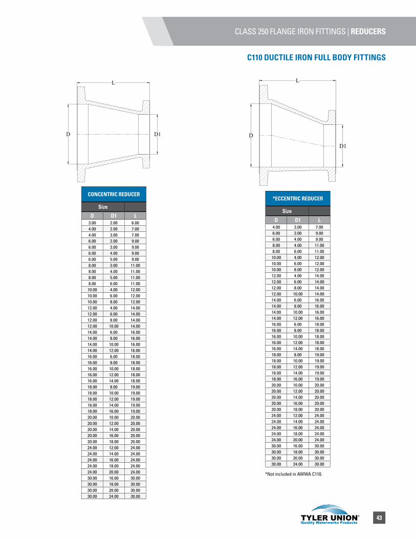
43
CLASS 250 FLANGE IRON FITTINGS | REDUCERS
C110 DUCTILE IRON FULL BODY FITTINGS
CONCENTRIC REDUCER
Size
D D1 L3.00 2.00 6.004.00 2.00 7.004.00 3.00 7.006.00 2.00 9.006.00 3.00 9.006.00 4.00 9.006.00 5.00 9.008.00 3.00 11.008.00 4.00 11.008.00 5.00 11.008.00 6.00 11.00
10.00 4.00 12.0010.00 6.00 12.0010.00 8.00 12.0012.00 4.00 14.0012.00 6.00 14.0012.00 8.00 14.0012.00 10.00 14.0014.00 6.00 16.0014.00 8.00 16.0014.00 10.00 16.0014.00 12.00 16.0016.00 6.00 18.0016.00 8.00 18.0016.00 10.00 18.0016.00 12.00 18.0016.00 14.00 18.0018.00 8.00 19.0018.00 10.00 19.0018.00 12.00 19.0018.00 14.00 19.0018.00 16.00 19.0020.00 10.00 20.0020.00 12.00 20.0020.00 14.00 20.0020.00 16.00 20.0020.00 18.00 20.0024.00 12.00 24.0024.00 14.00 24.0024.00 16.00 24.0024.00 18.00 24.0024.00 20.00 24.0030.00 16.00 30.0030.00 18.00 30.0030.00 20.00 30.0030.00 24.00 30.00
*ECCENTRIC REDUCER
Size
D D1 L4.00 3.00 7.006.00 3.00 9.006.00 4.00 9.008.00 4.00 11.008.00 6.00 11.00
10.00 4.00 12.0010.00 6.00 12.0010.00 8.00 12.0012.00 4.00 14.0012.00 6.00 14.0012.00 8.00 14.0012.00 10.00 14.0014.00 6.00 16.0014.00 8.00 16.0014.00 10.00 16.0014.00 12.00 16.0016.00 6.00 18.0016.00 8.00 18.0016.00 10.00 18.0016.00 12.00 18.0016.00 14.00 18.0018.00 8.00 19.0018.00 10.00 19.0018.00 12.00 19.0018.00 14.00 19.0018.00 16.00 19.0020.00 10.00 20.0020.00 12.00 20.0020.00 14.00 20.0020.00 16.00 20.0020.00 18.00 20.0024.00 12.00 24.0024.00 14.00 24.0024.00 16.00 24.0024.00 18.00 24.0024.00 20.00 24.0030.00 16.00 30.0030.00 18.00 30.0030.00 20.00 30.0030.00 24.00 30.00
L
D D1
L
D
D1
*Not included in AWWA C110.
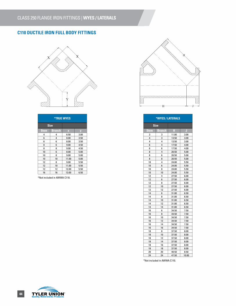
44
CLASS 250 FLANGE IRON FITTINGS | WYES / LATERALS
C110 DUCTILE IRON FULL BODY FITTINGS
*TRUE WYES
Size
Stem Branch x y4 4 6.50 3.006 4 8.00 3.506 6 8.00 3.508 6 9.00 4.508 8 9.00 4.50
10 6 8.00 5.0010 8 9.00 5.0010 10 11.00 5.0012 8 9.00 5.5012 10 11.00 5.5012 12 12.00 5.5016 16 13.00 6.50
*WYES / LATERALS
Size
Stem Branch H J3 3 11.00 3.004 3 13.50 3.004 4 13.50 3.006 4 17.50 4.006 6 17.50 4.008 4 20.50 5.008 6 20.50 5.008 8 20.50 5.0010 4 24.00 5.5010 6 24.00 5.5010 8 24.00 5.5010 10 24.00 5.5012 4 27.50 6.0012 6 27.50 6.0012 8 27.50 6.0012 10 27.50 6.0012 12 27.50 6.0014 6 31.00 6.5014 8 31.00 6.5014 10 31.00 6.5014 12 31.00 6.5014 14 31.00 6.5016 6 34.50 7.5016 8 34.50 7.5016 10 34.50 7.5016 12 34.50 7.5016 14 34.50 7.5016 16 34.50 7.5018 8 37.50 8.0018 10 37.50 8.0018 12 37.50 8.0018 14 37.50 8.0018 16 37.50 8.0018 18 37.50 8.0020 20 40.50 8.5024 24 47.50 10.00
Y
XX
H J
H
*Not included in AWWA C110.
*Not included in AWWA C110.
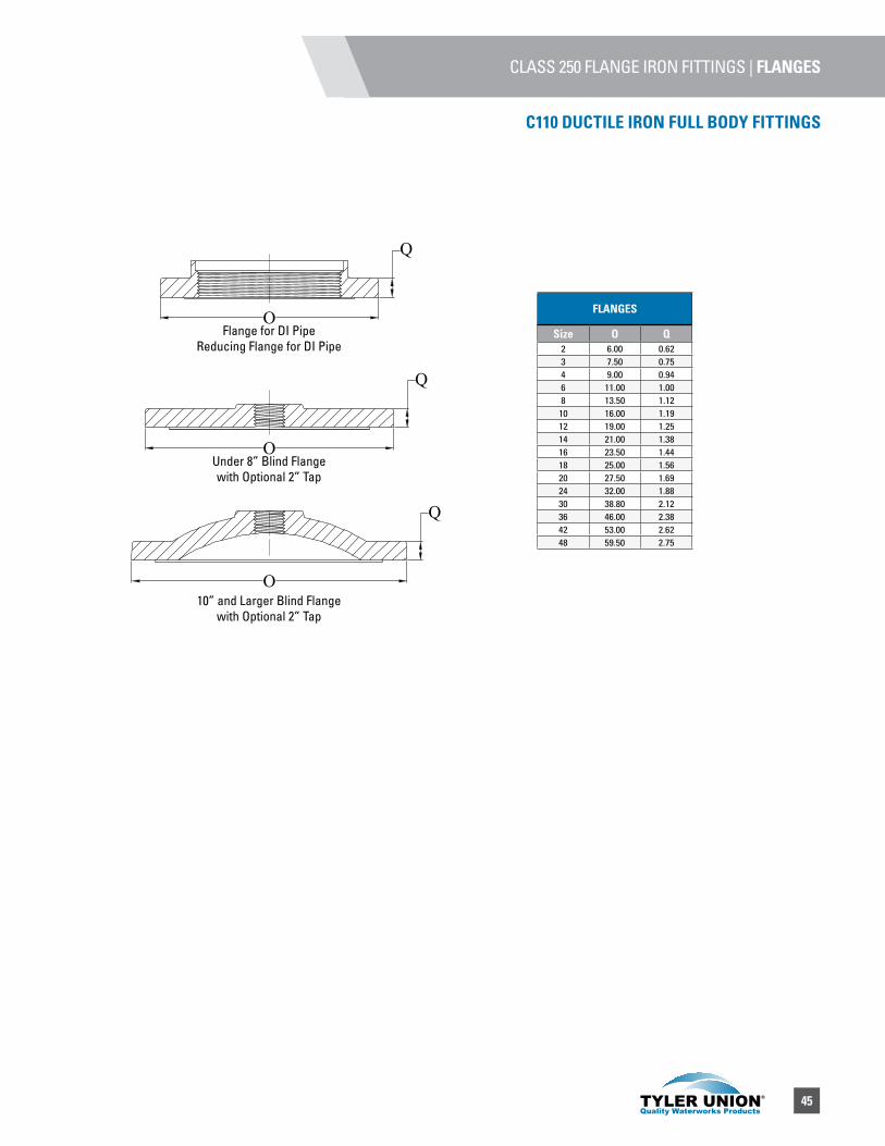
45
CLASS 250 FLANGE IRON FITTINGS | FLANGES
C110 DUCTILE IRON FULL BODY FITTINGS
FLANGES
Size O Q2 6.00 0.623 7.50 0.754 9.00 0.946 11.00 1.008 13.50 1.12
10 16.00 1.1912 19.00 1.2514 21.00 1.3816 23.50 1.4418 25.00 1.5620 27.50 1.6924 32.00 1.8830 38.80 2.1236 46.00 2.3842 53.00 2.6248 59.50 2.75
Q
Q
Q
O
O
O
Flange for DI PipeReducing Flange for DI Pipe
Under 8” Blind Flange with Optional 2” Tap
10” and Larger Blind Flange with Optional 2” Tap

46
6500 SERIES
CAST IRON SCREW TYPE VALVE BOXESfor 1 1/4” through 2” curbstops, enlarged base accommodates 2” curbstops, 2 1/2 shaft — screw type
6500 SERIES, SCREW TYPE ASSEMBLIES WITH WATER LID
BOX (components) UPC 670610 Weight Extensions In inches
**(ND) UPC 670610 Weight
89-A {12T & 12B) 146681 20 15–21 111863 2090-8 (12T & 15B) 146742 21 18–24 111870 2190-C {15T & 15B) 146803 22 21–27 111887 2491-C {15T & 21B) 146865 24 24–33 111894 2692-C {15T & 27B) 146926 26 30–39 111900 2892-D {18T & 27B) 146988 28 30–42 111917 2993-0 (18T & 33B) 147046 32 36–48 111924 3393-E (24T & 33B) 147114 37 36–54 111931 3994-E (24T & 39B) 147183 41 42–60 111948 4495-E (30T & 39B) 147251 44 41–64 111955 49
100-E (24T & 21B & #154 Ext) 147312 50 54–72 111832 55100-F (30T & 21B & #154 Ext) 147381 53 54–78 111849 59101-F (30T & 27B & #154 Ext) 147459 55 60–84 111856 61
2 3/4
6 5/8
3 3/16
9/1
6
2 5/16
1.50
VA
RIA
BLE
5 3
/4
2 3/4
1/4
3 1
1/16
3 3/8
8 15/16
9 5
/8
2 7/8
3 3/8
4
5 3
/4
5 1/16
1/4
4
3/4
2 3/4
VA
RIA
BLE
1 1
/2
3 7/16
3 7/8
3/8
3 7/16
2 1
/2
VA
RIA
BLE
1/4
TOP SECTION WITH WATER LID
Item **D-UPC 670610 Weight **(ND)
UPC 670610 Weight
12T 147510 11 112006 1215T 147589 12 112013 1518T 147640 14 112020 1624T 147701 19 112037 2230T 147763 22 112044 27
BOTTOM ONLY
Item **D-UPC 670610 Weight **(ND)
UPC 670610 Weight
12B 144670 9 136941 815B 144687 10 111788 921B 144694 12 111795 1127B 144700 14 111801 1333B 144717 18 111818 1739B 144724 22 111825 22
6500 PARTS
Item **D-UPC 670610 Weight **(ND)
UPC 670610 Weight Height Increase
151 Extension 144762 7 111962 9 9152 Extension 144779 12 111979 14 16153 Extension 144786 17 111786 21 28154 Extension 144793 19 111993 21 30Enlarged Base 144806 8 136934 11 6
2 1/2 '' Water Lid 144830 1 – – –Brass Screw 144816 – – – –
Wrench 144908 0.5 – – –2 1/2 '' Repair Lid
Outside cover 385518 4.5 – – –
** D=Domestic ND=Import
** D=Domestic ND=Import
** D=Domestic ND=Import
** D=Domestic ND=Import
2
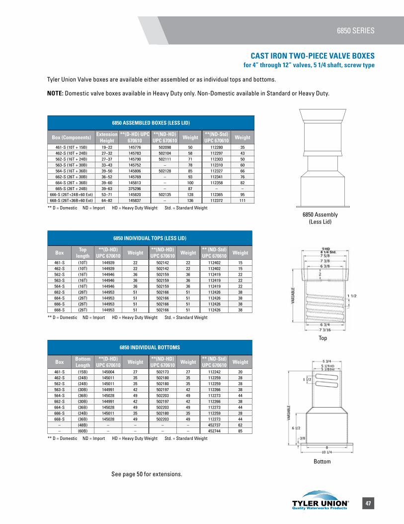
47
6850 SERIES
CAST IRON TWO-PIECE VALVE BOXES for 4” through 12” valves, 5 1/4 shaft, screw type
6850 ASSEMBLED BOXES (LESS LID)
Box (Components) Extension Height
**(D-HD) UPC 670610
**(ND-HD) UPC 670610 Weight **(ND-Std)
UPC 670610 Weight
461-S (10T + 15B) 19–22 145776 502098 50 112280 35462-S (10T + 24B) 27–32 145783 502104 58 112297 43562-S (16T + 24B) 27–37 145790 502111 71 112303 50563-S (16T + 30B) 33–43 145752 – 78 112310 60564-S (16T + 36B) 39–50 145806 502128 85 112327 66662-S (26T + 30B) 36–52 145769 – 93 112341 76664-S (26T + 36B) 39–60 145813 – 100 112358 82665-S (26T + 24B) 39–63 375296 – 87 – –
666-S (26T+24B+60 Ext) 53–71 145820 502135 128 112365 95668-S (26T+36B+60 Ext) 64–82 145837 – 136 112372 111
6850 INDIVIDUAL TOPS (LESS LID)
Box Top length
**(D-HD) UPC 670610 Weight **(ND-HD)
UPC 670610 Weight ** (ND-Std) UPC 670610 Weight
461-S (10T) 144939 22 502142 22 112402 15462-S (10T) 144939 22 502142 22 112402 15562-S (16T) 144946 36 502159 36 112419 22563-S (16T) 144946 36 502159 36 112419 22564-S (16T) 144946 36 502159 36 112419 22662-S (26T) 144953 51 502166 51 112426 38664-S (26T) 144953 51 502166 51 112426 38666-S (26T) 144953 51 502166 51 112426 38668-S (26T) 144953 51 502166 51 112426 38
6850 INDIVIDUAL BOTTOMS
Box Bottom Length
**(D-HD) UPC 670610 Weight **(ND-HD)
UPC 670610 Weight ** (ND-Std) UPC 670610 Weight
461-S (15B) 145004 27 502173 27 112242 20462-S (24B) 145011 35 502180 35 112259 28562-S (24B) 145011 35 502180 35 112259 28563-S (30B) 144991 42 502197 42 112266 38564-S (36B) 145028 49 502203 49 112273 44662-S (30B) 144991 42 502197 42 112266 38664-S (36B) 145028 49 502203 49 112273 44666-S (24B) 145011 35 502180 35 112259 28668-S (36B) 145028 49 502203 49 112273 44
– (48B) – – – – 452737 62– (60B) – – – – 452744 85
Tyler Union Valve boxes are available either assembled or as individual tops and bottoms.
NOTE: Domestic valve boxes available in Heavy Duty only. Non-Domestic available in Standard or Heavy Duty.
** D = Domestic ND = Import HD = Heavy Duty Weight Std. = Standard Weight
** D = Domestic ND = Import HD = Heavy Duty Weight Std. = Standard Weight
** D = Domestic ND = Import HD = Heavy Duty Weight Std. = Standard Weight
See page 50 for extensions.
6850 Assembly (Less Lid)
Top
Bottom
1 1/2
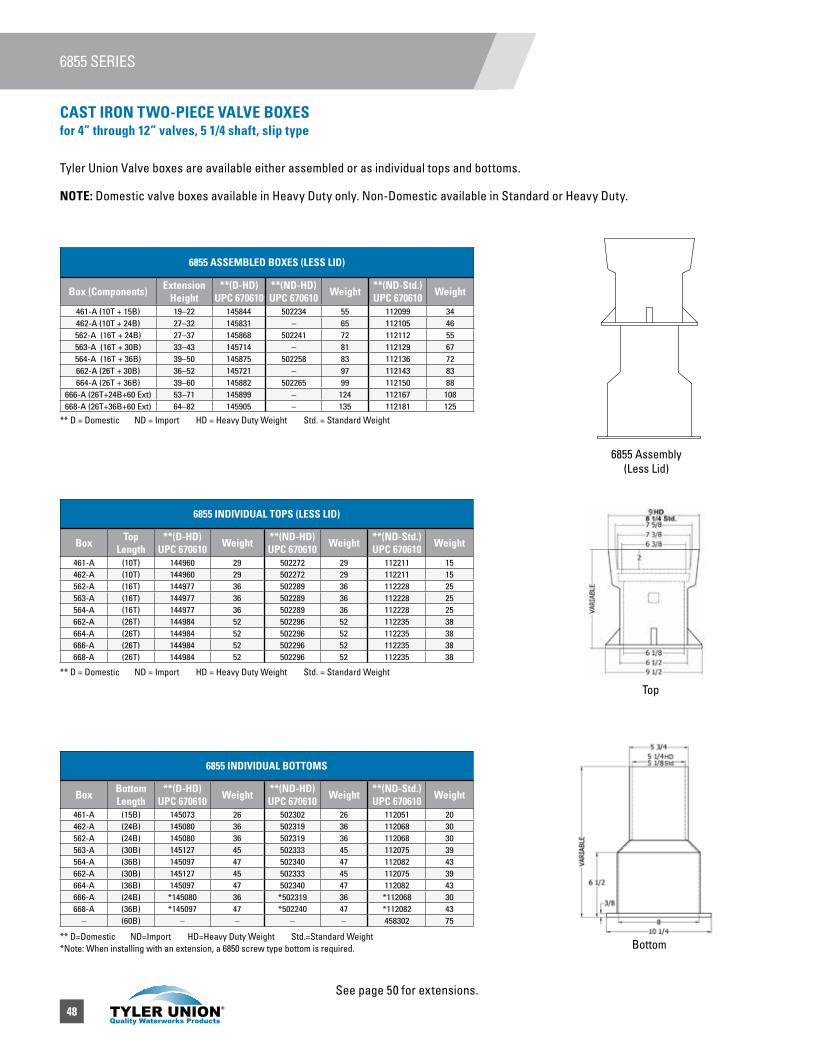
48
6855 ASSEMBLED BOXES (LESS LID)
Box (Components) Extension Height
**(D-HD) UPC 670610
**(ND-HD) UPC 670610 Weight **(ND-Std.)
UPC 670610 Weight
461-A (10T + 15B) 19–22 145844 502234 55 112099 34462-A (10T + 24B) 27–32 145831 – 65 112105 46562-A (16T + 24B) 27–37 145868 502241 72 112112 55563-A (16T + 30B) 33–43 145714 – 81 112129 67564-A (16T + 36B) 39–50 145875 502258 83 112136 72662-A (26T + 30B) 36–52 145721 – 97 112143 83664-A (26T + 36B) 39–60 145882 502265 99 112150 88
666-A (26T+24B+60 Ext) 53–71 145899 – 124 112167 108668-A (26T+36B+60 Ext) 64–82 145905 – 135 112181 125
6855 SERIES
** D = Domestic ND = Import HD = Heavy Duty Weight Std. = Standard Weight
** D = Domestic ND = Import HD = Heavy Duty Weight Std. = Standard Weight
** D=Domestic ND=Import HD=Heavy Duty Weight Std.=Standard Weight *Note: When installing with an extension, a 6850 screw type bottom is required.
6855 INDIVIDUAL TOPS (LESS LID)
Box TopLength
**(D-HD) UPC 670610 Weight **(ND-HD)
UPC 670610 Weight **(ND-Std.) UPC 670610 Weight
461-A (10T) 144960 29 502272 29 112211 15462-A (10T) 144960 29 502272 29 112211 15562-A (16T) 144977 36 502289 36 112228 25563-A (16T) 144977 36 502289 36 112228 25564-A (16T) 144977 36 502289 36 112228 25662-A (26T) 144984 52 502296 52 112235 38664-A (26T) 144984 52 502296 52 112235 38666-A (26T) 144984 52 502296 52 112235 38668-A (26T) 144984 52 502296 52 112235 38
6855 INDIVIDUAL BOTTOMS
Box Bottom Length
**(D-HD) UPC 670610 Weight **(ND-HD)
UPC 670610 Weight **(ND-Std.) UPC 670610 Weight
461-A (15B) 145073 26 502302 26 112051 20462-A (24B) 145080 36 502319 36 112068 30562-A (24B) 145080 36 502319 36 112068 30563-A (30B) 145127 45 502333 45 112075 39564-A (36B) 145097 47 502340 47 112082 43662-A (30B) 145127 45 502333 45 112075 39664-A (36B) 145097 47 502340 47 112082 43666-A (24B) *145080 36 *502319 36 *112068 30668-A (36B) *145097 47 *502240 47 *112082 43
– (60B) – – – – 458302 75
6855 Assembly (Less Lid)
Top
Bottom
Tyler Union Valve boxes are available either assembled or as individual tops and bottoms.
NOTE: Domestic valve boxes available in Heavy Duty only. Non-Domestic available in Standard or Heavy Duty.
CAST IRON TWO-PIECE VALVE BOXESfor 4” through 12” valves, 5 1/4 shaft, slip type
See page 50 for extensions.

49
6860 ASSEMBLED BOXES (LESS LID)
Box (Components) Extension Height
**(D-HD) UPC 670610
**(ND-HD) UPC 670610 Weight **(ND-Std.)
UPC 670610 Weight
AA (10T + 12B) 27–37 145912 – 42 136668 29A (16T + 18B) 33–42 145929 – 65 136651 38B (16T + 24B) 39–49 145936 – 69 136675 51C (16T + 30B) 45–54 145943 – 73 136682 55
CC (16T + 36B) 51–60 145950 – 75 136699 59D (26T + 30B) 45–66 145967 502357 88 136811 71
DD (26T + 36B) 51–72 145974 502364 90 136828 75E (16T+24B+60 Ext) 63–72 145981 – 105 136835 80F (26T+24B+60 Ext) 63–84 145998 – 120 136842 96G (26T+36B+60 Ext) 74–94 146001 502371 126 136859 104
6860 SERIES
** D = Domestic ND = Import HD = Heavy Duty Weight Std. = Standard Weight
** D = Domestic ND = Import HD = Heavy Duty Weight Std. = Standard Weight
** D=Domestic ND=Import HD=Heavy Duty Weight Std.=Standard Weight
6860 INDIVIDUAL TOPS (LESS LID)
Box TOPLength
**(D-HD) UPC 670610 Weight **(ND-HD)
UPC 670610 Weight **(ND-Std.) UPC 670610 Weight
AA (10T) 144939 23 502142 23 112402 15A (10T) 144939 23 502142 23 112402 15B (16T) 144946 36 502159 36 112419 22C (16T) 144946 36 502159 36 112419 22
CC (16T) 144946 36 502159 36 112419 22D (26T) 144953 51 502166 52 112426 38
DD (26T) 144953 51 502166 52 112426 38E (16T) 144946 36 502159 36 112419 22F (26T) 144953 51 502166 52 112426 38G (26T) 144953 51 502166 52 112426 38
6860 INDIVIDUAL BOTTOMS
Box Bottom Length
**(D-HD) UPC 670610 Weight **(ND-HD)
UPC 670610 Weight **(ND-Std.) UPC 670610 Weight
AA (12B) 145134 19 – – 250524 14A (18B) 145141 29 505594 29 250517 25B (24B) 145158 33 502388 33 136958 29C (30B) 145165 37 502395 37 136613 33
CC (36B) 145172 39 502401 39 136620 35D (30B) 145165 37 502395 37 136613 33
DD (36B) 145172 39 502401 39 136620 35E (24B) 145158 33 502388 33 136958 29F (24B) 145158 33 502388 33 136958 29G (36B) 145172 39 502401 39 136620 35– (48B) – – – – 452713 65– (60B) – – – – 452720 91
6860 Assembly (Less Lid)
5 1/4
5 3/4
1 1/2
VARI
ABLE
1/42 3/8
1/2
7
8 1/8
7/8
4 1/4
Top
Bottom
Base illustratedfor position only
not furnished
Tyler Union Valve boxes are available either assembled or as individual tops and bottoms.
NOTE: Domestic valve boxes available in Heavy Duty only. Non-Domestic available in Standard or Heavy Duty.
CAST IRON THREE-PIECE VALVE BOXES for 3” through 20” valves, 5 1/4 shaft, screw type
(Base required, order separately)
See page 50 for extensions.
1 1/2

50
6860 BASES
Item Description **(D-HD)UPC 670610 Weight **(ND)UPC
670610 Weight **(ND-Std)UPC 670610 Weight
#4,11 1/4" Wide 145653 42 – 34 381532 22#6,14 3/4" Wide 145660 38 502432 45 381525 36
#160, 20 1/2" Wide 145684 71 502425 68 256861 55
6855 EXTENSIONS
Item/Description Height Increase
**(D-HD) UPC 670610 Weight **(ND-Std.)
UPC 670610 Weight
#58-A Slip-Type 6-14 145233 29 136637 26#59-A Slip-Type 6-18 145240 30 136644 28#60-A Slip-Type 6-24 145066 36 112198 37
6850/60 EXTENSIONS
Item/Description Height Increase
**(D-HD) UPC 670610 Weight **(ND-HD)
UPC 670610 Weight **(ND-Std.)UPC 670610 Weight
#58 Screw-Type 14 145141 32 505594 29 250517 23#59 Screw-Type 18 145158 30 – – 136958 29#60 Screw-Type 24 145059 39 502210 36 112389 29
BASES AND EXTENSION
** D = Domestic ND = Import HD = Heavy Duty Weight Std. = Standard Weight
** D = Domestic ND = Import HD = Heavy Duty Weight Std. = Standard Weight *NOTE: When installing these extensions, a 6850 screw type bottom is required.
** D = Domestic ND = Import HD = Heavy Duty Weight Std. = Standard Weight
#4 Base #6 Base #160 Base
58 & 59 60
58-A & 59-A 60-A
CAST IRON THREE-PIECE VALVE BOXES for 3” through 20” valves, 5 1/4 shaft, screw type(Base required, order separately)
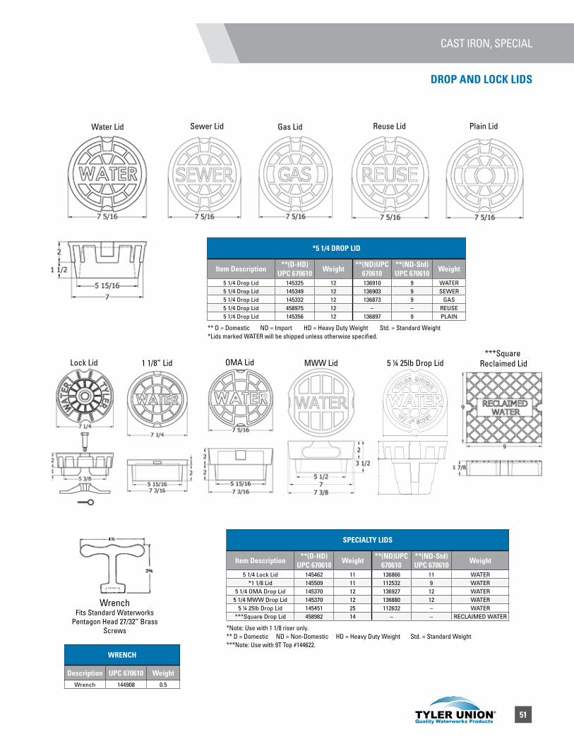
51
CAST IRON, SPECIAL
SPECIALTY LIDS
Item Description **(D-HD)UPC 670610 Weight **(ND)UPC
670610**(ND-Std)UPC 670610 Weight
5 1/4 Lock Lid 145462 11 136866 11 WATER*1 1/8 Lid 145509 11 112532 9 WATER
5 1/4 OMA Drop Lid 145370 12 136927 12 WATER5 1/4 MWW Drop Lid 145370 12 136880 12 WATER
5 ¼ 25lb Drop Lid 145451 25 112632 – WATER***Square Drop Lid 458982 14 – – RECLAIMED WATER
WRENCH
Description UPC 670610 WeightWrench 144908 0.5
Water Lid Sewer Lid Gas Lid Reuse Lid Plain Lid
** D = Domestic ND = Import HD = Heavy Duty Weight Std. = Standard Weight *Lids marked WATER will be shipped unless otherwise specified.
*5 1/4 DROP LID
Item Description **(D-HD)UPC 670610 Weight **(ND)UPC
670610**(ND-Std)UPC 670610 Weight
5 1/4 Drop Lid 145325 12 136910 9 WATER5 1/4 Drop Lid 145349 12 136903 9 SEWER5 1/4 Drop Lid 145332 12 136873 9 GAS5 1/4 Drop Lid 458975 12 – – REUSE5 1/4 Drop Lid 145356 12 136897 9 PLAIN
Lock Lid 1 1/8” Lid OMA Lid MWW Lid 5 ¼ 25lb Drop Lid***Square
Reclaimed Lid
WrenchFits Standard Waterworks
Pentagon Head 27/32” BrassScrews *Note: Use with 1 1/8 riser only.
** D = Domestic ND = Non-Domestic HD = Heavy Duty Weight Std. = Standard Weight***Note: Use with 9T Top #144622.
DROP AND LOCK LIDS
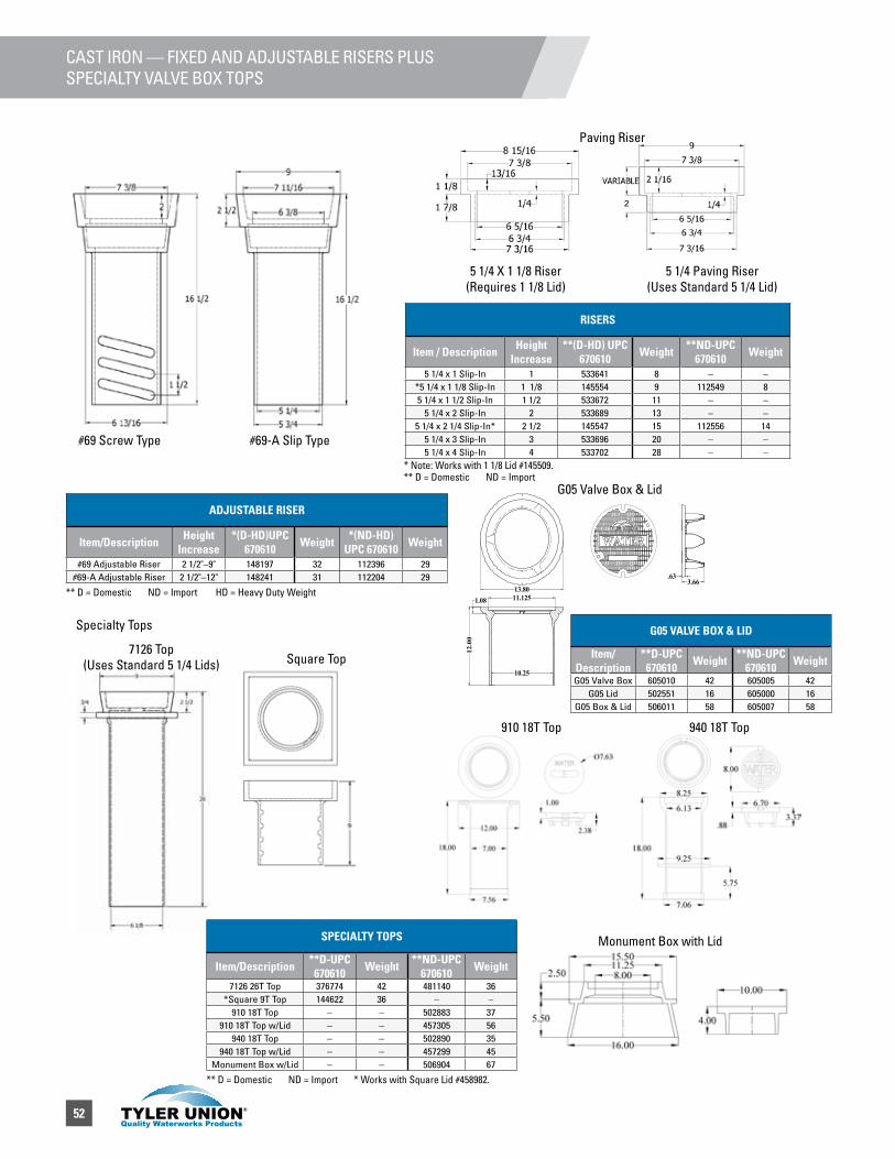
52
CAST IRON — FIXED AND ADJUSTABLE RISERS PLUSSPECIALTY VALVE BOX TOPS
ADJUSTABLE RISER
Item/Description Height Increase
*(D-HD)UPC 670610 Weight *(ND-HD)
UPC 670610 Weight
#69 Adjustable Riser 2 1/2"–9" 148197 32 112396 29#69-A Adjustable Riser 2 1/2"–12" 148241 31 112204 29
** D = Domestic ND = Import HD = Heavy Duty Weight
RISERS
Item / Description Height Increase
**(D-HD) UPC 670610 Weight **ND-UPC
670610 Weight
5 1/4 x 1 Slip-In 1 533641 8 – –*5 1/4 x 1 1/8 Slip-In 1 1/8 145554 9 112549 85 1/4 x 1 1/2 Slip-In 1 1/2 533672 11 – –
5 1/4 x 2 Slip-In 2 533689 13 – –5 1/4 x 2 1/4 Slip-In* 2 1/2 145547 15 112556 14
5 1/4 x 3 Slip-In 3 533696 20 – –5 1/4 x 4 Slip-In 4 533702 28 – –
* Note: Works with 1 1/8 Lid #145509.** D = Domestic ND = Import
G05 VALVE BOX & LID
Item/Description
**D-UPC 670610 Weight **ND-UPC
670610 Weight
G05 Valve Box 605010 42 605005 42G05 Lid 502551 16 605000 16
G05 Box & Lid 506011 58 605007 58
#69-A Slip Type#69 Screw Type
5 1/4 X 1 1/8 Riser(Requires 1 1/8 Lid)
5 1/4 Paving Riser(Uses Standard 5 1/4 Lid)
Paving Riser
7126 Top(Uses Standard 5 1/4 Lids) Square Top
940 18T Top910 18T Top
Specialty Tops
Monument Box with Lid
G05 Valve Box & Lid
** D = Domestic ND = Import * Works with Square Lid #458982.
SPECIALTY TOPS
Item/Description **D-UPC 670610 Weight **ND-UPC
670610 Weight
7126 26T Top 376774 42 481140 36*Square 9T Top 144622 36 – –
910 18T Top – – 502883 37910 18T Top w/Lid – – 457305 56
940 18T Top – – 502890 35940 18T Top w/Lid – – 457299 45
Monument Box w/Lid – – 506904 67
3.6613.80
.63
11.125
12.00
1.08
10.25
2
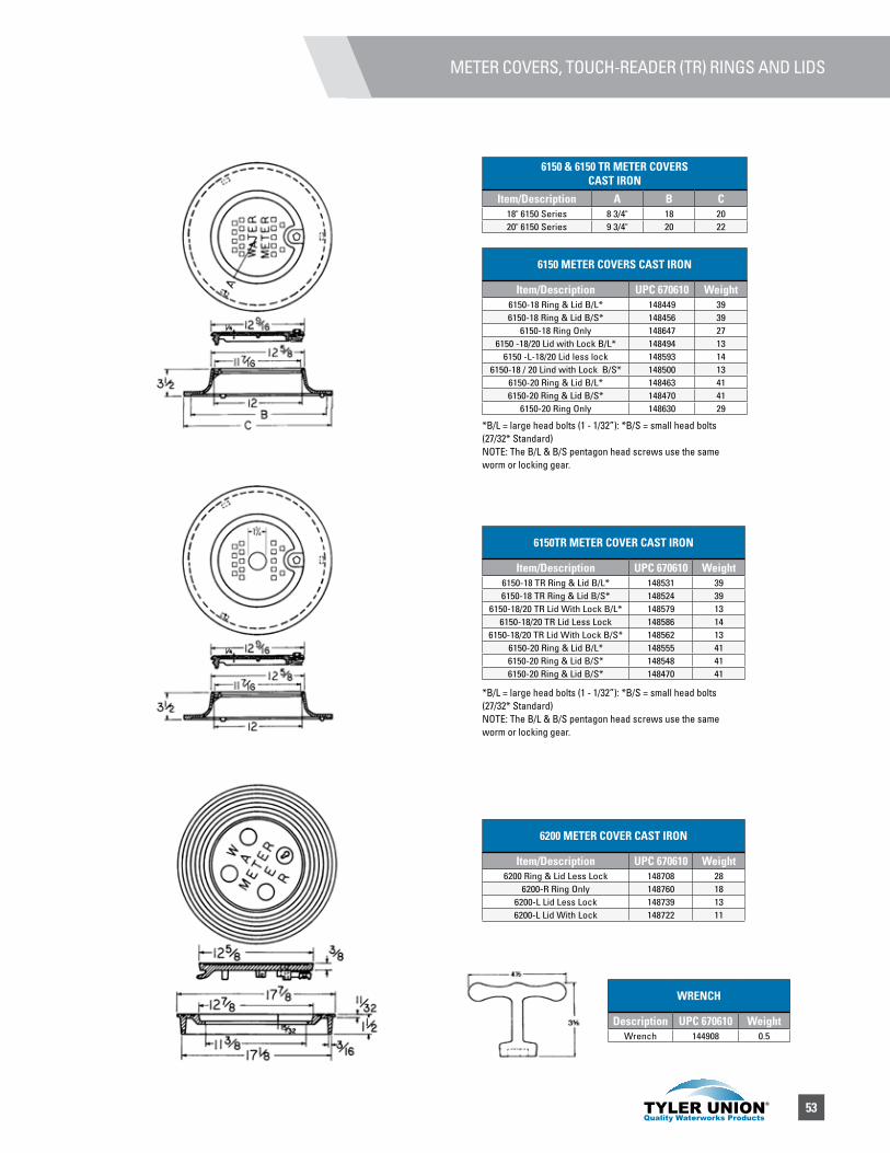
53
METER COVERS, TOUCH-READER (TR) RINGS AND LIDS
6150 & 6150 TR METER COVERS CAST IRON
Item/Description A B C18" 6150 Series 8 3/4" 18 2020" 6150 Series 9 3/4" 20 22
6150 METER COVERS CAST IRON
Item/Description UPC 670610 Weight6150-18 Ring & Lid B/L* 148449 396150-18 Ring & Lid B/S* 148456 39
6150-18 Ring Only 148647 276150 -18/20 Lid with Lock B/L* 148494 13
6150 -L-18/20 Lid less lock 148593 146150-18 / 20 Lind with Lock B/S* 148500 13
6150-20 Ring & Lid B/L* 148463 416150-20 Ring & Lid B/S* 148470 41
6150-20 Ring Only 148630 29
6150TR METER COVER CAST IRON
Item/Description UPC 670610 Weight6150-18 TR Ring & Lid B/L* 148531 396150-18 TR Ring & Lid B/S* 148524 39
6150-18/20 TR Lid With Lock B/L* 148579 136150-18/20 TR Lid Less Lock 148586 14
6150-18/20 TR Lid With Lock B/S* 148562 136150-20 Ring & Lid B/L* 148555 416150-20 Ring & Lid B/S* 148548 416150-20 Ring & Lid B/S* 148470 41
6200 METER COVER CAST IRON
Item/Description UPC 670610 Weight6200 Ring & Lid Less Lock 148708 28
6200-R Ring Only 148760 186200-L Lid Less Lock 148739 136200-L Lid With Lock 148722 11
*B/L = large head bolts (1 - 1/32”): *B/S = small head bolts (27/32* Standard) NOTE: The B/L & B/S pentagon head screws use the same worm or locking gear.
*B/L = large head bolts (1 - 1/32”): *B/S = small head bolts (27/32* Standard) NOTE: The B/L & B/S pentagon head screws use the same worm or locking gear.
WRENCH
Description UPC 670610 WeightWrench 144908 0.5
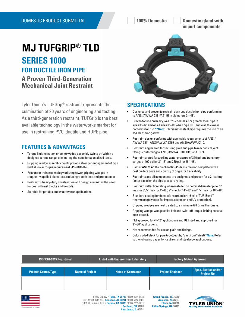
100% Domestic Available
11910 CR 492 / Tyler, TX 75706 / (800) 527-84781501 West 17th St. / Anniston, AL 36201 / (800) 226-76011001 El Camino Ave. / Corona, CA 92879 / (866) 527-8471
Portland, OR 97203New Lenox, IL 60451
Grand Prairie, TX 75050Anniston, AL 36207
Elmer, NJ 08318Lithia Springs, GA 30122
Tyler Union’s TUFGrip® restraint represents the culmination of 20 years of engineering and testing. As a third-generation restraint, TUFGrip is the best available technology in the waterworks market for use in restraining PVC, ductile and HDPE pipe.
SPECIFICATIONS• Designed and proven to restrain plain end ductile iron pipe conforming
to ANSI/AWWA C151/A21.51 in diameters 3"–48".
• Proven for use on heavy wall. **Schedule 40 or greater steel pipe in sizes 3"–12" and on all sizes 3"–16" when pipe O.D. and wall thickness conforms to C151 **Note: IPS diameter steel pipe requires the use of an MJ Transition gasket .
• Restraint design conforms with applicable requirements of ANSI/AWWA C111, ANSI/AWWA C153 and ANSI/AWWA C110.
• Restraint engineered for securing plain end pipe to mechanical joint fittings conforming to ANSI/AWWA C110, C111 and C153 .
• Restraints rated for working water pressure of 350 psi and transitory surges of 100 psi for 3"–16" and 250 psi for 18"–48".
• Cast of ASTM A536 compliant 65-45-12 ductile iron complete with a cast on date code and country of origin for traceability.
• Restraints and all components are designed and proven for a 2:1 safety factor based on the pipe pressure rating.
• Restraint deflection rating when installed on nominal diameter pipe: 3° max for 3", 5° max for 4"–12", 2° max for 14"–16" and 1.5° max for 18"–48".
• Standard coating for domestic restraint is 4–6 mil of TUF-Bond™ (thermoset polyester for impact, corrosion and UV protection).
• Gripping wedges are heat treated to a mininum 420 Brinell hardness.
• Gripping wedge, wedge collar bolt and twist-off torque limiting nut shall be e-coated.
• FM approved for 4"–12" applications and UL listed and approved for 3"–36" applications.
• Not recommended for use on plain end fittings.
• Color coded black for pipe type(ductile/*cast iron/*steel) *Note: Refer to the following pages for cast iron and steel pipe applications.
FEATURES & ADVANTAGES• Torque limiting nut on gripping wedge assembly twists off within a
designed torque range, eliminating the need for specialized tools.
• Gripping wedge assembly pivots provide stronger engagement of pipe wall at lower torque requirement (45–60 ft-lb).
• Proven restraint technology utilizing fewer gripping wedges in frequently applied diameters, reducing trench time and project cost .
• Restraint’s heavy-duty construction and design eliminates the need for costly thrust blocks and tie rods.
• Suitable for potable and wastewater applications.
SERIES 1000 FOR DUCTILE IRON PIPEA Proven Third-Generation Mechanical Joint Restraint
MJ TUFGRIP® TLD
DOMESTIC PRODUCT SUBMITTAL
Product Source/Type Name of Project Name of Contractor Project EngineerSpec. Section and/or
Project No.
ISO 9001-2015 Registered Listed with Underwriters Laboratory Factory Mutual Approved
100% Domestic Domestic gland withimport components
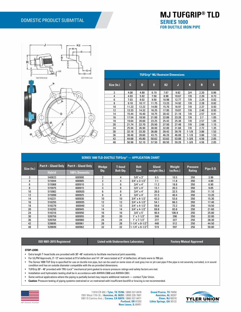
100% Domestic Available
11910 CR 492 / Tyler, TX 75706 / (800) 527-84781501 West 17th St. / Anniston, AL 36201 / (800) 226-76011001 El Camino Ave. / Corona, CA 92879 / (866) 527-8471
Portland, OR 97203New Lenox, IL 60451
Grand Prairie, TX 75050Anniston, AL 36207
Elmer, NJ 08318Lithia Springs, GA 30122
DOMESTIC PRODUCT SUBMITTAL
SERIES 1000 TLD-DUCTILE TUFGrip® — APPLICATION CHART
Size (In.)Part # – Gland Only Part # – Gland Only Wedge
Qty.T-head
Bolt Qty.Bolt Size
Gland weight (lbs.)
Weight(w/Acc.)
Pressure Rating
Pipe O.D.Hybrid 100% Domestic
3 540823 600900 2 4 5/8" x 3" 6.5 10.5 350 3.964 515944 600905 2 4 3/4" x 3-1/2" 7.1 11.8 350 4.806 515968 600910 3 6 3/4" x 4" 11.2 18.8 350 6.908 515975 600915 3 6 3/4" x 4" 13.1 20.3 350 9.0510 515982 600920 6 8 3/4" x 4" 26.0 32.5 350 11.1012 515999 600925 8 8 3/4" x 4" 31.5 40.4 350 13.2014 516231 600930 10 10 3/4" x 4-1/2" 43.3 53.6 350 15.3016 516255 600935 12 12 3/4" x 4-1/2" 54.1 66.3 350 17.4018 516279 600940 12 12 3/4" x 4-1/2" 59.8 72.2 250 19.5020 516293 600945 14 14 3/4" x 4-1/2" 69.8 83.8 250 21.6024 516316 600950 16 16 3/4" x 5" 90.4 106.9 250 25.8030 539759 600955 20 20 1" x 7-1/2" 248 290 250 32.0036 539764 600960 24 24 1" x 7-1/2" 277 327 250 38.3042 539695 600961 28 28 1-1/4" x 8-1/2" 448 512 250 44.5048 539699 600962 32 32 1-1/4" x 8-1/2" 519 597 250 50.80
TUFGrip® MJ Restraint Dimensions
Size (In.) C D E K2 J K R S
3 4.08 4.88 6.19 7.67 9.82 3/4 2.20 0.864 4.93 5.92 7.50 8.98 10.67 7/8 2.20 0.736 7.03 8.02 9.50 10.98 12.77 7/8 2.24 0.828 9.18 10.17 11.75 13.23 14.92 7/8 2.28 0.82
10 11.23 12.22 14.00 15.70 16.97 7/8 2.37 0.9312 13.33 14.32 16.25 17.95 19.07 7/8 2.40 0.9314 15.44 16.40 18.75 20.43 21.18 7/8 2.57 0.9116 17.54 18.50 21.00 22.88 23.28 7/8 2.7 1.0518 19.64 20.60 23.25 25.43 25.38 7/8 2.57 1.0520 21.74 22.70 25.50 27.50 27.48 7/8 2.66 1.1524 25.94 26.90 30.00 32.00 31.68 7/8 2.72 1.3530 32.18 33.30 36.88 39.42 39.78 1-1/8 3.86 1.5336 38.48 39.60 43.75 46.29 46.08 1-1/8 3.86 1.5342 44.68 45.80 50.62 53.62 53.08 1-3/8 4.56 2.0548 50.98 52.10 57.50 60.50 59.28 1-3/8 4.56 2.05
ISO 9001-2015 Registered Listed with Underwriters Laboratory Factory Mutual Approved
STOP-LOOK:
• Extra length T-head bolts are provided with 30"–48" restraints to facilitate mechanical joint assembly.• For UL/FM Approvals, 3"–12" were tested at 5°of deflection and 14"–24" were tested at 3° of deflection; all tests were to 700 psi.• The Series 1000 TUF Grip is specified for use on ductile iron pipe, but can be used on some sizes of cast grey iron or pit cast pipe if the pipe is not severely corroded, is in sound
condition and has an outside diameter compatible with the as provided dimensions.• TUFGrip 30"– 48" provided with TRU-Lock™ mechanical joint gasket to ensure pressure ratings and safety factors are met.• Installation and hydrostatic testing shall be in accordance with AWWA C600 and AWWA C651. • Some vertical applications where the piping is partially buried may require additional restraint — contact Tyler Union. • Caution: Pressure testing of piping systems restrained or un-restrained with insufficient backfill or bracing is not recommended.
SERIES 1000 FOR DUCTILE IRON PIPE
MJ TUFGRIP® TLD
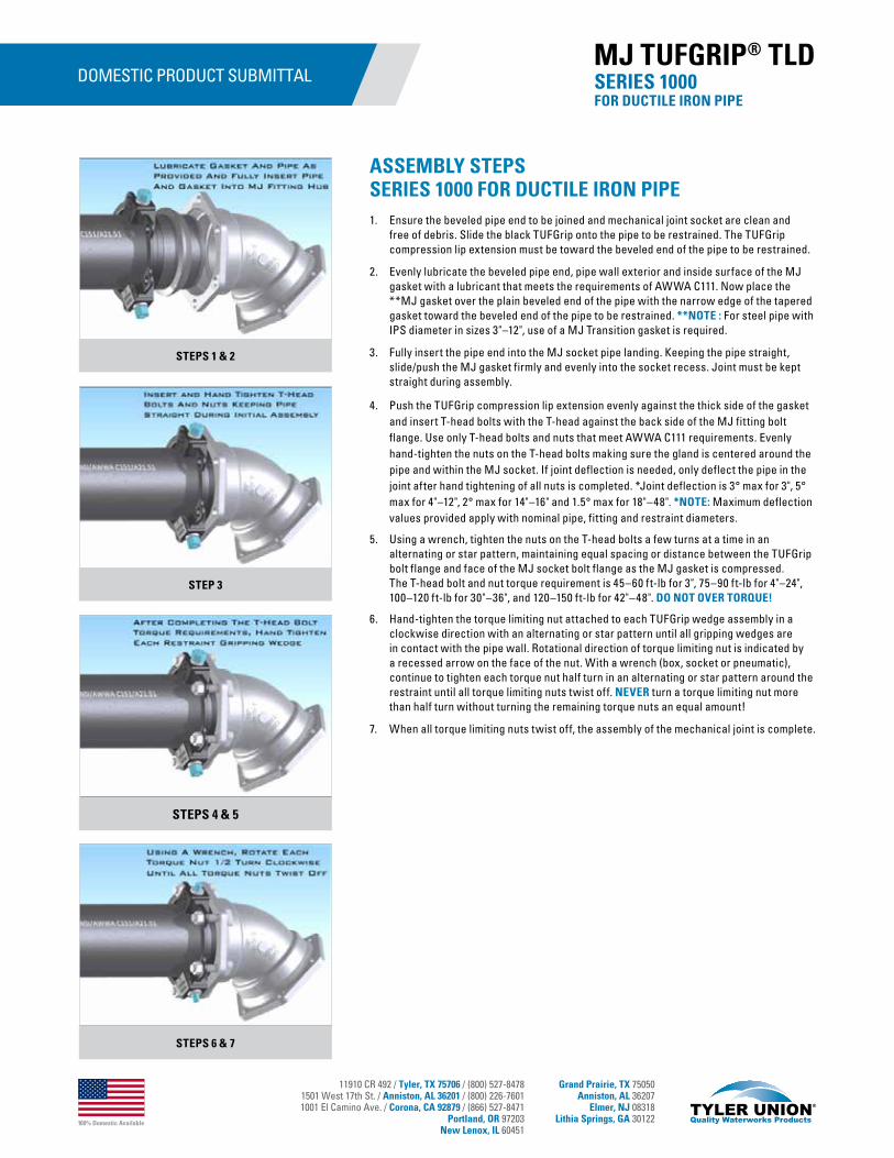
100% Domestic Available
11910 CR 492 / Tyler, TX 75706 / (800) 527-84781501 West 17th St. / Anniston, AL 36201 / (800) 226-76011001 El Camino Ave. / Corona, CA 92879 / (866) 527-8471
Portland, OR 97203New Lenox, IL 60451
Grand Prairie, TX 75050Anniston, AL 36207
Elmer, NJ 08318Lithia Springs, GA 30122
DOMESTIC PRODUCT SUBMITTAL SERIES 1000 FOR DUCTILE IRON PIPE
MJ TUFGRIP® TLD
STEPS 1 & 2
STEP 3
STEPS 4 & 5
STEPS 6 & 7
ASSEMBLY STEPSSERIES 1000 FOR DUCTILE IRON PIPE1. Ensure the beveled pipe end to be joined and mechanical joint socket are clean and
free of debris. Slide the black TUFGrip onto the pipe to be restrained. The TUFGrip compression lip extension must be toward the beveled end of the pipe to be restrained.
2. Evenly lubricate the beveled pipe end, pipe wall exterior and inside surface of the MJ gasket with a lubricant that meets the requirements of AWWA C111. Now place the **MJ gasket over the plain beveled end of the pipe with the narrow edge of the tapered gasket toward the beveled end of the pipe to be restrained. **NOTE : For steel pipe with IPS diameter in sizes 3"–12", use of a MJ Transition gasket is required.
3. Fully insert the pipe end into the MJ socket pipe landing. Keeping the pipe straight, slide/push the MJ gasket firmly and evenly into the socket recess. Joint must be kept straight during assembly.
4. Push the TUFGrip compression lip extension evenly against the thick side of the gasket and insert T-head bolts with the T-head against the back side of the MJ fitting bolt flange. Use only T-head bolts and nuts that meet AWWA C111 requirements. Evenly hand-tighten the nuts on the T-head bolts making sure the gland is centered around the pipe and within the MJ socket. If joint deflection is needed, only deflect the pipe in the joint after hand tightening of all nuts is completed. *Joint deflection is 3° max for 3", 5° max for 4"–12", 2° max for 14"–16" and 1.5° max for 18"–48". *NOTE: Maximum deflection values provided apply with nominal pipe, fitting and restraint diameters.
5. Using a wrench, tighten the nuts on the T-head bolts a few turns at a time in an alternating or star pattern, maintaining equal spacing or distance between the TUFGrip bolt flange and face of the MJ socket bolt flange as the MJ gasket is compressed. The T-head bolt and nut torque requirement is 45–60 ft-lb for 3", 75–90 ft-lb for 4"–24", 100–120 ft-lb for 30"–36", and 120–150 ft-lb for 42"–48". DO NOT OVER TORQUE!
6. Hand-tighten the torque limiting nut attached to each TUFGrip wedge assembly in a clockwise direction with an alternating or star pattern until all gripping wedges are in contact with the pipe wall. Rotational direction of torque limiting nut is indicated by a recessed arrow on the face of the nut. With a wrench (box, socket or pneumatic), continue to tighten each torque nut half turn in an alternating or star pattern around the restraint until all torque limiting nuts twist off. NEVER turn a torque limiting nut more than half turn without turning the remaining torque nuts an equal amount!
7. When all torque limiting nuts twist off, the assembly of the mechanical joint is complete.

11910 CR 492 / Tyler, TX 75706 / (800) 527-84781501 West 17th St. / Anniston, AL 36201 / (800) 226-76011001 El Camino Ave. / Corona, CA 92879 / (866) 527-8471
Portland, OR 97203New Lenox, IL 60451
Grand Prairie, TX 75050Anniston, AL 36207
Elmer, NJ 08318Lithia Springs, GA 30122
Tyler Union’s TUFGrip® restraint represents the culmination of 20 years of engineering and testing. As a third-generation restraint, TUFGrip is the best available technology in the waterworks market for use in restraining PVC, ductile and HDPE pipe.
SPECIFICATIONS• Designed and proven to restrain plain end ductile iron pipe conforming
to ANSI/AWWA C151/A21.51 in diameters 3"–48".
• Proven for use on heavy wall. **Schedule 40 or greater steel pipe in sizes 3"–12" and on all sizes 3"–16" when pipe O.D. and wall thickness conforms to C151. **Note: IPS diameter steel pipe requires the use of an MJ Transition gasket.
• Restraint design conforms with applicable requirements of ANSI/AWWA C111, ANSI/AWWA C153 and ANSI/AWWA C110.
• Restraint engineered for securing plain end pipe to Mechanical joint fittings conforming to ANSI/AWWA C110, C111 and C153.
• Restraints rated for working water pressure of 350 psi and transitory surges of 100psi for 3"–16" and 250 psi for 18"–48".
• Cast of ASTM A536 compliant 65-45-12 ductile iron complete with a cast on date code and country of origin for traceability.
• Restraints and all components are designed and proven for a 2:1 safety factor based on the pipe pressure rating.
• Restraint deflection rating when installed on nominal diameter pipe: 3° max for 3", 5° max for 4"–12", 2° max for 14"–16", and 1.5° max for 18"–48".
• Standard coating for non-domestic restraint is 4-6 mil of *alkyd resin baking enamel.
• Gripping wedges are heat treated to a mininum 420 Brinell hardness.
• Gripping wedge, wedge collar bolt and twist-off torque limiting nut shall be e-coated.
• FM approved for 4"–12" applications and UL listed and approved for 3"–36" applications.
• Not recommended for use on plain end fittings.
• Color coded black for pipe type(ductile/*cast iron/*steel). *Note: Refer to the following pages for cast iron and steel pipe applications.
FEATURES & ADVANTAGES• Torque limiting nut on gripping wedge assembly twists off within a
designed torque range, eliminating the need for specialized tools.
• Gripping wedge assembly pivots providing stronger engagement of pipe wall at lower torque requirement (45–60 ft-lb).
• Proven restraint technology utilizing fewer gripping wedges in frequently applied diameters, reducing trench time and project cost.
• Restraint’s heavy-duty construction and design eliminates the need for costly thrust blocks and tie rods.
• Suitable for potable and wastewater applications.
SERIES 1000 FOR DUCTILE IRON PIPEA Proven Third-Generation Mechanical Joint Restraint
MJ TUFGRIP® TLD
NON-DOMESTIC PRODUCT SUBMITTAL
Product Source/Type Name of Project Name of Contractor Project EngineerSpec. Section and/or
Project No.
ISO 9001-2015 Registered Listed with Underwriters Laboratory Factory Mutual Approved
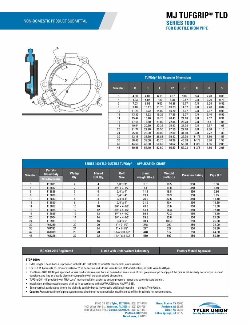
11910 CR 492 / Tyler, TX 75706 / (800) 527-84781501 West 17th St. / Anniston, AL 36201 / (800) 226-76011001 El Camino Ave. / Corona, CA 92879 / (866) 527-8471
Portland, OR 97203New Lenox, IL 60451
Grand Prairie, TX 75050Anniston, AL 36207
Elmer, NJ 08318Lithia Springs, GA 30122
NON-DOMESTIC PRODUCT SUBMITTAL
SERIES 1000 TLD-DUCTILE TUFGrip® — APPLICATION CHART
Size (In.)
Part # – Gland Only Wedge
Qty.T-head
Bolt Qty.Bolt Size
Gland weight (lbs.)
Weight(w/Acc.)
Pressure Rating Pipe O.D.Non-Domestic
3 113805 2 4 5/8" x 3" 6.5 10.5 350 3.964 113812 2 4 3/4" x 3-1/2" 7.1 11.8 350 4.806 113829 3 6 3/4" x 4" 11.2 18.8 350 6.908 113836 3 6 3/4" x 4" 13.1 20.3 350 9.0510 113843 6 8 3/4" x 4" 26.0 32.5 350 11.1012 113850 8 8 3/4" x 4" 31.5 40.4 350 13.2014 113867 10 10 3/4" x 4-1/2" 43.3 53.6 350 15.3016 113874 12 12 3/4" x 4-1/2" 54.1 66.3 350 17.4018 113898 12 12 3/4" x 4-1/2" 59.8 72.2 250 19.5020 113904 14 14 3/4" x 4-1/2" 69.8 83.8 250 21.6024 113911 16 16 3/4" x 5" 90.4 106.9 250 25.8030 461289 20 20 1" x 7-1/2" 248 290 250 32.0036 461333 24 24 1" x 7-1/2" 277 327 250 38.3042 461319 28 28 1-1/4" x 8-1/2" 448 512 250 44.5048 461326 32 32 1-1/4" x 8-1/2" 519 597 250 50.80
TUFGrip® MJ Restraint Dimensions
Size (In.) C D E K2 J K R S
3 4.08 4.88 6.19 7.67 9.82 3/4 2.20 0.864 4.93 5.92 7.50 8.98 10.67 7/8 2.20 0.736 7.03 8.02 9.50 10.98 12.77 7/8 2.24 0.828 9.18 10.17 11.75 13.23 14.92 7/8 2.28 0.82
10 11.23 12.22 14.00 15.70 16.97 7/8 2.37 0.9312 13.33 14.32 16.25 17.95 19.07 7/8 2.40 0.9314 15.44 16.40 18.75 20.43 21.18 7/8 2.57 0.9116 17.54 18.50 21.00 22.88 23.28 7/8 2.7 1.0518 19.64 20.60 23.25 25.43 25.38 7/8 2.57 1.0520 21.74 22.70 25.50 27.50 27.48 7/8 2.66 1.1524 25.94 26.90 30.00 32.00 31.68 7/8 2.72 1.3530 32.18 33.30 36.88 39.42 39.78 1-1/8 3.86 1.5336 38.48 39.60 43.75 46.29 46.08 1-1/8 3.86 1.5342 44.68 45.80 50.62 53.62 53.08 1-3/8 4.56 2.0548 50.98 52.10 57.50 60.50 59.28 1-3/8 4.56 2.05
ISO 9001-2015 Registered Listed with Underwriters Laboratory Factory Mutual Approved
STOP-LOOK:
• Extra length T-head bolts are provided with 30"–48" restraints to facilitate mechanical joint assembly.• For UL/FM Approvals, 3"–12" were tested at 5° of deflection and 14"–24" were tested at 3° of deflection; all tests were to 700 psi.• The Series 1000 TUFGrip is specified for use on ductile iron pipe but can be used on some sizes of cast grey iron or pit cast pipe if the pipe is not severely corroded, is in sound
condition, and has an outside diameter compatible with the as provided dimensions. • TUFGrip 30"– 48" provided with TRU-Lock™ mechanical joint gasket to ensure pressure ratings and safety factors are met.• Installation and hydrostatic testing shall be in accordance with AWWA C600 and AWWA C651. • Some vertical applications where the piping is partially buried may require additional restraint — contact Tyler Union. • Caution: Pressure testing of piping systems restrained or un-restrained with insufficient backfill or bracing is not recommended.
SERIES 1000 FOR DUCTILE IRON PIPE
MJ TUFGRIP® TLD
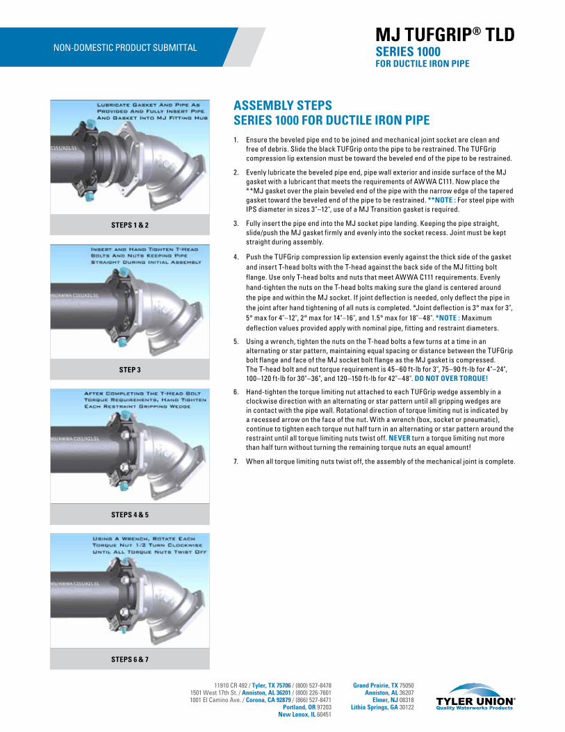
11910 CR 492 / Tyler, TX 75706 / (800) 527-84781501 West 17th St. / Anniston, AL 36201 / (800) 226-76011001 El Camino Ave. / Corona, CA 92879 / (866) 527-8471
Portland, OR 97203New Lenox, IL 60451
Grand Prairie, TX 75050Anniston, AL 36207
Elmer, NJ 08318Lithia Springs, GA 30122
NON-DOMESTIC PRODUCT SUBMITTAL SERIES 1000 FOR DUCTILE IRON PIPE
MJ TUFGRIP® TLD
STEPS 1 & 2
STEP 3
STEPS 4 & 5
STEPS 6 & 7
ASSEMBLY STEPSSERIES 1000 FOR DUCTILE IRON PIPE1. Ensure the beveled pipe end to be joined and mechanical joint socket are clean and
free of debris. Slide the black TUFGrip onto the pipe to be restrained. The TUFGrip compression lip extension must be toward the beveled end of the pipe to be restrained.
2. Evenly lubricate the beveled pipe end, pipe wall exterior and inside surface of the MJ gasket with a lubricant that meets the requirements of AWWA C111. Now place the **MJ gasket over the plain beveled end of the pipe with the narrow edge of the tapered gasket toward the beveled end of the pipe to be restrained. **NOTE : For steel pipe with IPS diameter in sizes 3"–12", use of a MJ Transition gasket is required.
3. Fully insert the pipe end into the MJ socket pipe landing. Keeping the pipe straight, slide/push the MJ gasket firmly and evenly into the socket recess. Joint must be kept straight during assembly.
4. Push the TUFGrip compression lip extension evenly against the thick side of the gasket and insert T-head bolts with the T-head against the back side of the MJ fitting bolt flange. Use only T-head bolts and nuts that meet AWWA C111 requirements. Evenly hand-tighten the nuts on the T-head bolts making sure the gland is centered around the pipe and within the MJ socket. If joint deflection is needed, only deflect the pipe in the joint after hand tightening of all nuts is completed. *Joint deflection is 3° max for 3", 5° max for 4"–12", 2° max for 14"–16", and 1.5° max for 18"–48". *NOTE : Maximum deflection values provided apply with nominal pipe, fitting and restraint diameters.
5. Using a wrench, tighten the nuts on the T-head bolts a few turns at a time in an alternating or star pattern, maintaining equal spacing or distance between the TUFGrip bolt flange and face of the MJ socket bolt flange as the MJ gasket is compressed. The T-head bolt and nut torque requirement is 45–60 ft-lb for 3", 75–90 ft-lb for 4"–24", 100–120 ft-lb for 30"–36", and 120–150 ft-lb for 42"–48". DO NOT OVER TORQUE!
6. Hand-tighten the torque limiting nut attached to each TUFGrip wedge assembly in a clockwise direction with an alternating or star pattern until all gripping wedges are in contact with the pipe wall. Rotational direction of torque limiting nut is indicated by a recessed arrow on the face of the nut. With a wrench (box, socket or pneumatic), continue to tighten each torque nut half turn in an alternating or star pattern around the restraint until all torque limiting nuts twist off. NEVER turn a torque limiting nut more than half turn without turning the remaining torque nuts an equal amount!
7. When all torque limiting nuts twist off, the assembly of the mechanical joint is complete.

11910 CR 492 / Tyler, TX 75706 / (800) 527-84781501 West 17th St. / Anniston, AL 36201 / (800) 226-76011001 El Camino Ave. / Corona, CA 92879 / (866) 527-8471
Portland, OR 97203New Lenox, IL 60451
Grand Prairie, TX 75050Anniston, AL 36207
Elmer, NJ 08318Lithia Springs, GA 30122
SPECIFICATIONS• Designed and proven to restrain plain end ductile iron pipe
conforming to ANSI/AWWA C151/A21.51 in diameters 4"–12".
• Restraint design conforms with applicable requirements of ANSI/AWWA C111, ANSI/AWWA C153 and ANSI/AWWA C110.
• Restraint engineered for securing plain end pipe to mechanical joint fittings conforming to ANSI/AWWA C110, C111 and C153.
• Restraint rated for working water pressure of 350 psi for 4"–12" restraints.
• Cast of ASTM A536 compliant 65-45-12 ductile iron complete with a cast on date code and country of origin for traceability.
• Restraints and all components are designed and proven for a 2:1 safety factor based on the pipe pressure rating.
• Deflection rating when installed on AWWA C151 pipe with nominal diameter shall be 3° for 4"–12" restraints.
• Standard coating for Non-Domestic restraint is 4-6 mil of *alkyd resin baking enamel. *Note: Epoxy coatings available upon request.
• Gripping wedges are heat treated to a mininum 420 Brinell hardness.
• Gripping wedge, wedge collar bolt and twist-off torque limiting nut shall be e-coated.
• Not recommended for use on plain end fittings.
• Color coded black for pipe type(ductile pipe/*cast iron pipe).*Note: Refer to the next page for cast iron pipe application.
FEATURES & ADVANTAGES• Torque limiting nut on gripping wedge assembly twists off within a
designed torque range, eliminating the need for specialized tools.
• Gripping wedge assembly pivots providing stronger engagement of pipe wall at lower torque requirement (45–60 ft.-lbs.).
• Proven restraint technology utilizing fewer gripping wedges in frequently applied diameters, reducing trench time and project cost.
• Restraint’s heavy-duty construction and design eliminates the need for costly thrust blocks and tie rods.
• Suitable for potable and wastewater applications.
PRODUCT SUBMITTAL
Product Source/Type Name of Project Name of Contractor Project EngineerSpec. Section and/or
Project No.
ISO 9001-2015 Registered
SERIES 1000S FOR DUCTILE IRON PIPEA Proven Third-Generation Mechanical Joint Restraint
MJ TUFGRIP™ TLD SPLIT
Tyler Union’s TUFGrip™ restraint represents the culmination of 20 years of engineering and testing. As a third-generation restraint, TUFGrip is the best available technology in the waterworks market for use in restraining PVC, ductile and HDPE pipe.
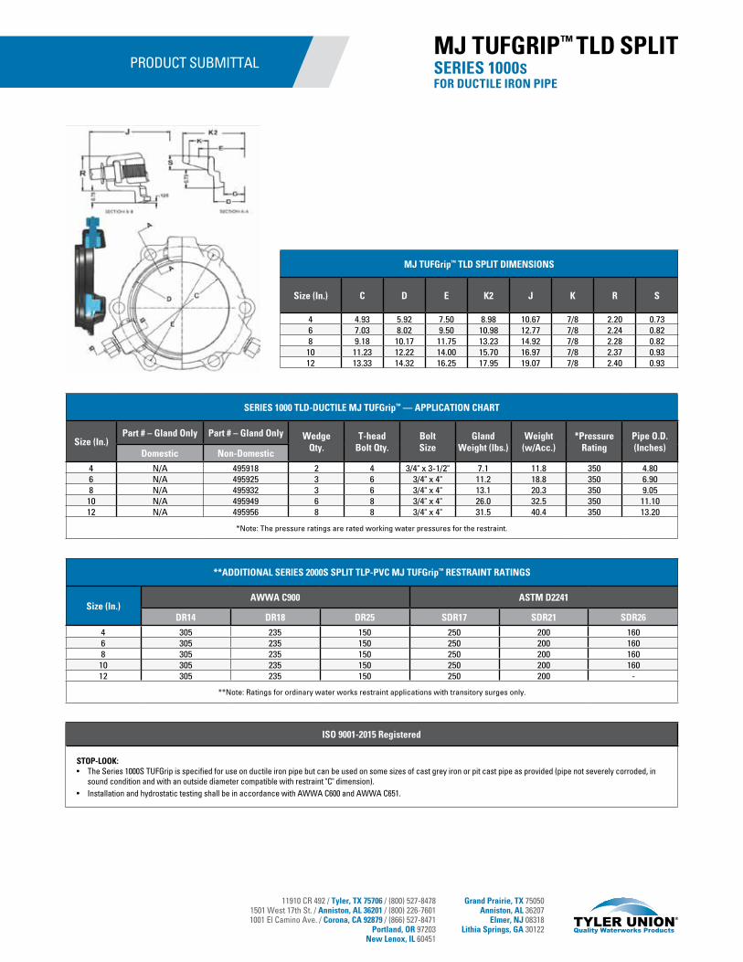
11910 CR 492 / Tyler, TX 75706 / (800) 527-84781501 West 17th St. / Anniston, AL 36201 / (800) 226-76011001 El Camino Ave. / Corona, CA 92879 / (866) 527-8471
Portland, OR 97203New Lenox, IL 60451
Grand Prairie, TX 75050Anniston, AL 36207
Elmer, NJ 08318Lithia Springs, GA 30122
PRODUCT SUBMITTAL
MJ TUFGrip™ TLD SPLIT DIMENSIONS
Size (In.) C D E K2 J K R S
4 4.93 5.92 7.50 8.98 10.67 7/8 2.20 0.736 7.03 8.02 9.50 10.98 12.77 7/8 2.24 0.828 9.18 10.17 11.75 13.23 14.92 7/8 2.28 0.82
10 11.23 12.22 14.00 15.70 16.97 7/8 2.37 0.9312 13.33 14.32 16.25 17.95 19.07 7/8 2.40 0.93
ISO 9001-2015 Registered
STOP-LOOK:• The Series 1000S TUFGrip is specified for use on ductile iron pipe but can be used on some sizes of cast grey iron or pit cast pipe as provided (pipe not severely corroded, in
sound condition and with an outside diameter compatible with restraint "C" dimension). • Installation and hydrostatic testing shall be in accordance with AWWA C600 and AWWA C651.
SERIES 1000 TLD-DUCTILE MJ TUFGrip™ — APPLICATION CHART
Size (In.)Part # – Gland Only Part # – Gland Only Wedge
Qty.T-head
Bolt Qty.Bolt Size
Gland Weight (lbs.)
Weight(w/Acc.)
*Pressure Rating
Pipe O.D. (Inches)Domestic Non-Domestic
4 N/A 495918 2 4 3/4" x 3-1/2" 7.1 11.8 350 4.806 N/A 495925 3 6 3/4" x 4" 11.2 18.8 350 6.908 N/A 495932 3 6 3/4" x 4" 13.1 20.3 350 9.0510 N/A 495949 6 8 3/4" x 4" 26.0 32.5 350 11.1012 N/A 495956 8 8 3/4" x 4" 31.5 40.4 350 13.20
*Note: The pressure ratings are rated working water pressures for the restraint.
**ADDITIONAL SERIES 2000S SPLIT TLP-PVC MJ TUFGrip™ RESTRAINT RATINGS
Size (In.)AWWA C900 ASTM D2241
DR14 DR18 DR25 SDR17 SDR21 SDR26
4 305 235 150 250 200 1606 305 235 150 250 200 1608 305 235 150 250 200 160
10 305 235 150 250 200 16012 305 235 150 250 200 -
**Note: Ratings for ordinary water works restraint applications with transitory surges only.
SERIES 1000SFOR DUCTILE IRON PIPE
MJ TUFGRIP™ TLD SPLIT
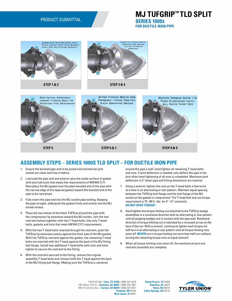
11910 CR 492 / Tyler, TX 75706 / (800) 527-84781501 West 17th St. / Anniston, AL 36201 / (800) 226-76011001 El Camino Ave. / Corona, CA 92879 / (866) 527-8471
Portland, OR 97203New Lenox, IL 60451
Grand Prairie, TX 75050Anniston, AL 36207
Elmer, NJ 08318Lithia Springs, GA 30122
PRODUCT SUBMITTAL
ASSEMBLY STEPS – SERIES 1000S TLD SPLIT – FOR DUCTILE IRON PIPE1. Ensure the beveled pipe end to be joined and mechanical joint
socket are clean and free of debris.
2. Lubricate the pipe end and exterior plus the inside surface of gasket with joint lubricant that meets the requirements of AWWA C111. Now place the MJ gasket over the plain beveled end of the pipe with the narrow edge of the tapered gasket toward the beveled end of the pipe to be restrained.
3. Fully insert the pipe end into the MJ socket pipe landing. Keeping the pipe straight, slide/push the gasket firmly and evenly into the MJ socket recess.
4. Place the two halves of the black TUFGrip around the pipe with the compression lip extension toward the MJ socket. Join the two restraint halves together with two T-head bolts. Use only T-head bolts, gaskets and nuts that meet AWWA C111 requirements.
5. With the two T-head bolts inserted through the restraint, push the TUFGrip lip extension evenly against the thick side of the MJ gasket. With the TUFGrip restraint against the gasket, the remaining T-head bolts are inserted with the T-head against the back of the MJ fitting bolt flange. Install two additional T-head bolts with nuts and hand tighten to secure the restraint to the fitting.
6. With the restraint secured to the fitting, remove the original assembly T-head bolts and reinsert with the T-head against the back of the MJ fitting bolt flange. Making sure the TUFGrip is centered
around the pipe’s wall, hand tighten all remaining T-head bolts and nuts. If joint deflection is needed, only deflect the pipe in the joint after hand tightening of all nuts is completed. Maximum joint deflection is 3° when pipe and fitting dimensions are nominal.
7. Using a wrench, tighten the nuts on the T-head bolts a few turns at a time in an alternating or star pattern. Maintain equal spacing between the TUFGrip bolt flange and the bolt flange of the MJ socket as the gasket is compressed. The T-head bolt and nut torque requirement is 75–90 ft.-lbs. for 4"–12" restraints. DO NOT OVER TORQUE!
8. Hand tighten the torque limiting nut attached to the TUFGrip wedge assemblies in a clockwise direction with an alternating or star pattern until all gripping wedges are in contact with the pipe wall. Rotational direction of torque limiting nut is indicated by a recessed arrow on the face of the nut. With a wrench, continue to tighten each torque nut half turn in an alternating or star pattern until all torque limiting nuts twist off. NEVER turn a torque limiting nut more than half turn without turning the remaining torque nuts an equal amount!
9. When all torque limiting nuts twist off, the mechanical joint and restraint assembly are complete.
SERIES 1000SFOR DUCTILE IRON PIPE
MJ TUFGRIP™ TLD SPLIT
STEP 1 & 2 STEP 3 & 4
STEP 5 STEP 8 & 9STEP 6 & 7
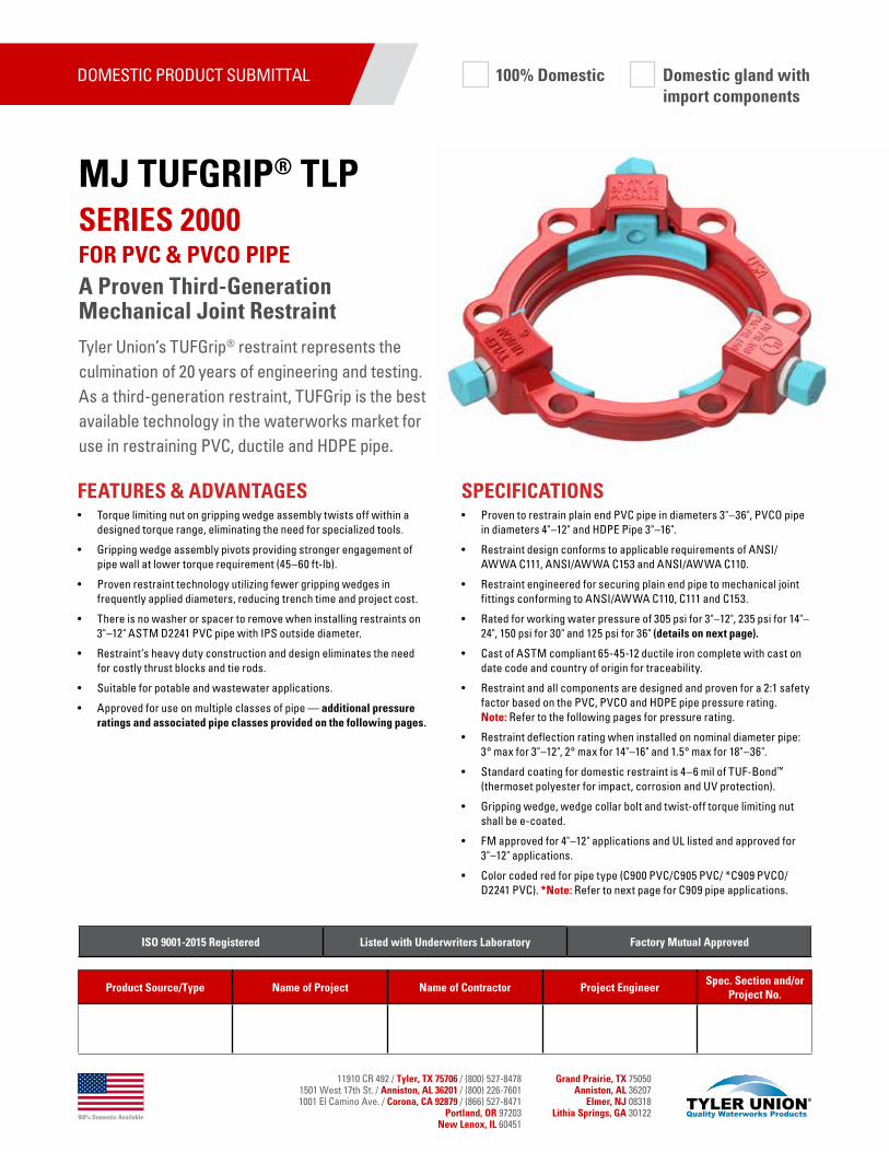
100% Domestic Available
11910 CR 492 / Tyler, TX 75706 / (800) 527-84781501 West 17th St. / Anniston, AL 36201 / (800) 226-76011001 El Camino Ave. / Corona, CA 92879 / (866) 527-8471
Portland, OR 97203New Lenox, IL 60451
Grand Prairie, TX 75050Anniston, AL 36207
Elmer, NJ 08318Lithia Springs, GA 30122
Tyler Union’s TUFGrip® restraint represents the culmination of 20 years of engineering and testing. As a third-generation restraint, TUFGrip is the best available technology in the waterworks market for use in restraining PVC, ductile and HDPE pipe.
SPECIFICATIONS• Proven to restrain plain end PVC pipe in diameters 3"–36", PVCO pipe
in diameters 4"–12" and HDPE Pipe 3"–16".
• Restraint design conforms to applicable requirements of ANSI/AWWA C111, ANSI/AWWA C153 and ANSI/AWWA C110.
• Restraint engineered for securing plain end pipe to mechanical joint fittings conforming to ANSI/AWWA C110, C111 and C153.
• Rated for working water pressure of 305 psi for 3"–12", 235 psi for 14"– 24", 150 psi for 30" and 125 psi for 36" (details on next page).
• Cast of ASTM compliant 65-45-12 ductile iron complete with cast on date code and country of origin for traceability.
• Restraint and all components are designed and proven for a 2:1 safety factor based on the PVC, PVCO and HDPE pipe pressure rating. Note: Refer to the following pages for pressure rating.
• Restraint deflection rating when installed on nominal diameter pipe: 3° max for 3"–12", 2° max for 14"–16" and 1.5° max for 18"–36".
• Standard coating for domestic restraint is 4–6 mil of TUF-Bond™ (thermoset polyester for impact, corrosion and UV protection).
• Gripping wedge, wedge collar bolt and twist-off torque limiting nut shall be e-coated.
• FM approved for 4"–12" applications and UL listed and approved for 3"–12" applications.
• Color coded red for pipe type (C900 PVC/C905 PVC/ *C909 PVCO/D2241 PVC). *Note: Refer to next page for C909 pipe applications.
FEATURES & ADVANTAGES• Torque limiting nut on gripping wedge assembly twists off within a
designed torque range, eliminating the need for specialized tools.
• Gripping wedge assembly pivots providing stronger engagement of pipe wall at lower torque requirement (45–60 ft-lb).
• Proven restraint technology utilizing fewer gripping wedges in frequently applied diameters, reducing trench time and project cost.
• There is no washer or spacer to remove when installing restraints on 3"–12" ASTM D2241 PVC pipe with IPS outside diameter.
• Restraint’s heavy duty construction and design eliminates the need for costly thrust blocks and tie rods.
• Suitable for potable and wastewater applications.
• Approved for use on multiple classes of pipe — additional pressure ratings and associated pipe classes provided on the following pages.
DOMESTIC PRODUCT SUBMITTAL
Product Source/Type Name of Project Name of Contractor Project EngineerSpec. Section and/or
Project No.
ISO 9001-2015 Registered Listed with Underwriters Laboratory Factory Mutual Approved
SERIES 2000 FOR PVC & PVCO PIPEA Proven Third-Generation Mechanical Joint Restraint
MJ TUFGRIP® TLP
100% Domestic Domestic gland withimport components

100% Domestic Available
11910 CR 492 / Tyler, TX 75706 / (800) 527-84781501 West 17th St. / Anniston, AL 36201 / (800) 226-76011001 El Camino Ave. / Corona, CA 92879 / (866) 527-8471
Portland, OR 97203New Lenox, IL 60451
Grand Prairie, TX 75050Anniston, AL 36207
Elmer, NJ 08318Lithia Springs, GA 30122
DOMESTIC PRODUCT SUBMITTAL
TUFGrip® MJ Restraint Dimensions
Size (In.) C D E K2 J K R S
3 4.08 4.88 6.19 7.67 9.82 3/4 2.20 0.864 4.93 5.92 7.50 8.98 10.67 7/8 2.20 0.736 7.03 8.02 9.50 10.98 12.77 7/8 2.24 0.828 9.18 10.17 11.75 13.23 14.92 7/8 2.28 0.82
10 11.23 12.22 14.00 15.70 16.97 7/8 2.37 0.9312 13.33 14.32 16.25 17.95 19.07 7/8 2.40 0.9314 15.44 16.40 18.75 20.43 21.18 7/8 2.57 0.9116 17.54 18.50 21.00 22.88 23.28 7/8 2.7 1.0518 19.64 20.60 23.25 25.43 25.38 7/8 2.57 1.0520 21.74 22.70 25.50 27.50 27.48 7/8 2.66 1.1524 25.94 26.90 30.00 32.00 31.68 7/8 2.72 1.3530 32.18 33.30 36.88 39.42 39.78 1-1/8 3.86 1.5336 38.48 39.60 43.75 46.29 46.08 1-1/8 3.86 1.53
ISO 9001-2015 Registered Listed with Underwriters Laboratory Factory Mutual Approved
STOP-LOOK:• Extra length T-head bolts are provided with 30"–36" restraints to facilitate mechanical joint assembly per AWWA C600.• For UL/FM approvals, 3"–12" were tested to 755 psi, 14"–16" were tested to 755 psi and 18"–24" were tested to 535 psi.• TUFGrip 30"- 36" provided with TRU-Lock™ Mechanical joint gasket to ensure pressure rating & safety factors are met.• Mechanical joint T-head bolt torques for C909 applications are as provided; *55–65 ft-lb for 4"–8" and *65–75 ft-lb for 10"–12" assembly. You must specifiy restraints are for C909
PVCO pipe upon order placement. Call for availability.• Installation and hydrostatic testing shall be in accordance with AWWA C600 and AWWA C651.• TUFGrip 4"–24" restraints shall meet the requirements of ASTM F1674, current revision.• Caution: Pressure testing of piping systems restrained or un-restrained with insufficient backfill or bracing is not recommended.
SERIES 2000 FOR PVC & PVCO PIPE
MJ TUFGRIP® TLP
SERIES 2000 TLP-PVC TUFGrip® — APPLICATION CHART
Size (In.)Part # – Gland Only Part # – Gland Only Wedge
Qty. T-head Bolt Qty.
Bolt Size
Gland weight (lbs.)
Weight(w/Acc.)
Pressure Rating
Pipe O.D.Hybrid 100% Domestic
3 CALL N/A 2 4 5/8" x 3" 7.0 11.0 *305 / DR14 3.504 516002 601000 2 4 3/4" x 3-1/2" 8.3 12.2 *305 / DR14 4.50-4.806 516019 601005 3 6 3/4" x 4" 12.4 18.3 *305 / DR14 6.63-6.908 516026 601010 3 6 3/4" x 4" 14.9 20.8 *305 / DR14 8.63-9.12
10 516033 601015 6 8 3/4" x 4" 25.7 33.4 *305 / DR14 10.75-11.1012 516040 601020 8 8 3/4" x 4" 34.1 42.0 *305 / DR14 12.75-13.2014 516248 601025 10 10 3/4" x 4-1/2" 45.1 55.4 *235 / DR18 15.3016 516262 601030 12 12 3/4" x 4-1/2" 56.2 68.4 *235 / DR18 17.4018 516286 601035 12 12 3/4" x 4-1/2" 62.4 74.8 *235 / DR25 19.5020 516309 601040 14 14 3/4" x 4-1/2" 72.9 86.9 *235 / DR25 21.6024 516323 601045 16 16 3/4" x 5" 93.2 109.8 *235 / DR25 25.8030 CALL CALL 20 20 1" x 7-1/2" 251 293 *150 / DR25 32.0036 CALL CALL 24 24 1" x 7-1/2" 281 331 *125 / DR25 38.30
*Note: The pressure ratings are rated working water pressures for the restraint. See page 3 for additional ratings.
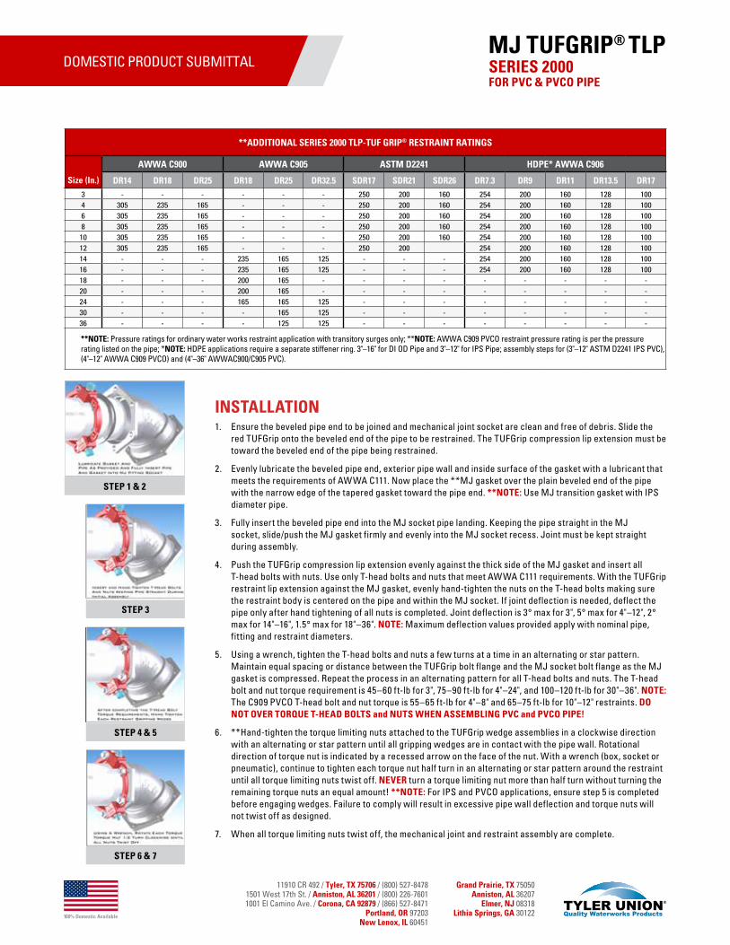
100% Domestic Available
11910 CR 492 / Tyler, TX 75706 / (800) 527-84781501 West 17th St. / Anniston, AL 36201 / (800) 226-76011001 El Camino Ave. / Corona, CA 92879 / (866) 527-8471
Portland, OR 97203New Lenox, IL 60451
Grand Prairie, TX 75050Anniston, AL 36207
Elmer, NJ 08318Lithia Springs, GA 30122
DOMESTIC PRODUCT SUBMITTAL
INSTALLATION1. Ensure the beveled pipe end to be joined and mechanical joint socket are clean and free of debris. Slide the
red TUFGrip onto the beveled end of the pipe to be restrained. The TUFGrip compression lip extension must be toward the beveled end of the pipe being restrained.
2. Evenly lubricate the beveled pipe end, exterior pipe wall and inside surface of the gasket with a lubricant that meets the requirements of AWWA C111. Now place the **MJ gasket over the plain beveled end of the pipe with the narrow edge of the tapered gasket toward the pipe end. **NOTE: Use MJ transition gasket with IPS diameter pipe.
3. Fully insert the beveled pipe end into the MJ socket pipe landing. Keeping the pipe straight in the MJ socket, slide/push the MJ gasket firmly and evenly into the MJ socket recess. Joint must be kept straight during assembly.
4. Push the TUFGrip compression lip extension evenly against the thick side of the MJ gasket and insert all T-head bolts with nuts. Use only T-head bolts and nuts that meet AWWA C111 requirements. With the TUFGrip restraint lip extension against the MJ gasket, evenly hand-tighten the nuts on the T-head bolts making sure the restraint body is centered on the pipe and within the MJ socket. If joint deflection is needed, deflect the pipe only after hand tightening of all nuts is completed. Joint deflection is 3° max for 3", 5° max for 4"–12", 2° max for 14"–16", 1.5° max for 18"–36". NOTE: Maximum deflection values provided apply with nominal pipe, fitting and restraint diameters.
5. Using a wrench, tighten the T-head bolts and nuts a few turns at a time in an alternating or star pattern. Maintain equal spacing or distance between the TUFGrip bolt flange and the MJ socket bolt flange as the MJ gasket is compressed. Repeat the process in an alternating pattern for all T-head bolts and nuts. The T-head bolt and nut torque requirement is 45–60 ft-lb for 3", 75–90 ft-lb for 4"–24", and 100–120 ft-lb for 30"–36". NOTE: The C909 PVCO T-head bolt and nut torque is 55–65 ft-lb for 4"–8" and 65–75 ft-lb for 10"–12" restraints. DO NOT OVER TORQUE T-HEAD BOLTS and NUTS WHEN ASSEMBLING PVC and PVCO PIPE!
6. **Hand-tighten the torque limiting nuts attached to the TUFGrip wedge assemblies in a clockwise direction with an alternating or star pattern until all gripping wedges are in contact with the pipe wall. Rotational direction of torque nut is indicated by a recessed arrow on the face of the nut. With a wrench (box, socket or pneumatic), continue to tighten each torque nut half turn in an alternating or star pattern around the restraint until all torque limiting nuts twist off. NEVER turn a torque limiting nut more than half turn without turning the remaining torque nuts an equal amount! **NOTE: For IPS and PVCO applications, ensure step 5 is completed before engaging wedges. Failure to comply will result in excessive pipe wall deflection and torque nuts will not twist off as designed.
7. When all torque limiting nuts twist off, the mechanical joint and restraint assembly are complete.
**ADDITIONAL SERIES 2000 TLP-TUF GRIP® RESTRAINT RATINGS
Size (In.)
AWWA C900 AWWA C905 ASTM D2241 HDPE* AWWA C906
DR14 DR18 DR25 DR18 DR25 DR32.5 SDR17 SDR21 SDR26 DR7.3 DR9 DR11 DR13.5 DR17
3 - - - - - - 250 200 160 254 200 160 128 1004 305 235 165 - - - 250 200 160 254 200 160 128 1006 305 235 165 - - - 250 200 160 254 200 160 128 1008 305 235 165 - - - 250 200 160 254 200 160 128 100
10 305 235 165 - - - 250 200 160 254 200 160 128 10012 305 235 165 - - - 250 200 254 200 160 128 10014 - - - 235 165 125 - - - 254 200 160 128 10016 - - - 235 165 125 - - - 254 200 160 128 10018 - - - 200 165 - - - - - - - - -20 - - - 200 165 - - - - - - - - -24 - - - 165 165 125 - - - - - - - -30 - - - - 165 125 - - - - - - - -36 - - - - 125 125 - - - - - - - -
**NOTE: Pressure ratings for ordinary water works restraint application with transitory surges only; **NOTE: AWWA C909 PVCO restraint pressure rating is per the pressure rating listed on the pipe; *NOTE: HDPE applications require a separate stiffener ring. 3"–16" for DI OD Pipe and 3"–12" for IPS Pipe; assembly steps for (3"–12" ASTM D2241 IPS PVC), (4"–12" AWWA C909 PVCO) and (4"–36" AWWAC900/C905 PVC).
STEP 1 & 2
STEP 3
STEP 4 & 5
STEP 6 & 7
SERIES 2000 FOR PVC & PVCO PIPE
MJ TUFGRIP® TLP

11910 CR 492 / Tyler, TX 75706 / (800) 527-84781501 West 17th St. / Anniston, AL 36201 / (800) 226-76011001 El Camino Ave. / Corona, CA 92879 / (866) 527-8471
Portland, OR 97203New Lenox, IL 60451
Grand Prairie, TX 75050Anniston, AL 36207
Elmer, NJ 08318Lithia Springs, GA 30122
Tyler Union’s TUFGrip® restraint represents the culmination of 20 years of engineering and testing. As a third-generation restraint, TUFGrip is the best available technology in the waterworks market for use in restraining PVC, ductile and HDPE pipe.
SPECIFICATIONS• Proven to restrain plain end PVC pipe in diameters 3"–36", PVCO pipe
in diameters 4"–12" and HDPE Pipe 4"–16".
• Restraint design conforms to applicable requirements of ANSI/AWWA C111, ANSI/AWWA C153 and ANSI/AWWA C110.
• Restraint engineered for securing plain end pipe to mechanical joint fittings conforming to ANSI/AWWA C110, C111 and C153.
• Rated for working water pressure of 305 psi for 3"–12", 235 psi for 14"–24", 150 psi for 30" and 125 psi for 36" (details on next page).
• Cast of ASTM compliant 65-45-12 ductile iron complete with cast on date code and country of origin for traceability.
• Restraint and all components are designed and proven for a 2:1 safety factor based on the PVC, PVCO and HDPE pipe pressure rating. Note: Refer to the following pages for pressure rating.
• Restraint deflection rating when installed on nominal diameter pipe: 3° max for 3"–12", 2° max for 14"–16", and 1.5° max for 18"–36".
• Standard coating for non-domestic restraint is 4–6 mil of alkyd resin baking enamel.
• Gripping wedge, wedge collar bolt and twist-off torque limiting nut shall be e-coated.
• FM approved for 4"–12" applications and UL listed and approved for 3"–12" applications.
• Color coded red for pipe type (C900 PVC/C905 PVC/ *C909 PVCO/D2241 PVC). *Note: Refer to next page for C909 pipe applications.
FEATURES & ADVANTAGES• Torque limiting nut on gripping wedge assembly twists off within a
designed torque range, eliminating the need for specialized tools.
• Gripping wedge assembly pivots providing stronger engagement of pipe wall at lower torque requirement (45–60 ft-lb).
• Proven restraint technology utilizing fewer gripping wedges in frequently applied diameters, reducing trench time and project cost.
• There is no washer or spacer to remove when installing restraints on 3"–12" ASTM D2241 PVC pipe with IPS outside diameter.
• Restraint’s heavy duty construction and design eliminates the need for costly thrust blocks and tie rods.
• Suitable for potable and wastewater applications.
• Approved for use on multiple classes of pipe — additional pressure ratings and associated pipe classes provided on the following pages.
NON-DOMESTIC PRODUCT SUBMITTAL
Product Source/Type Name of Project Name of Contractor Project EngineerSpec. Section and/or
Project No.
ISO 9001-2015 Registered Listed with Underwriters Laboratory Factory Mutual Approved
SERIES 2000 FOR PVC & PVCO PIPEA Proven Third-Generation Mechanical Joint Restraint
MJ TUFGRIP® TLP
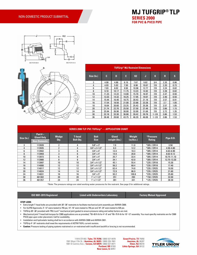
11910 CR 492 / Tyler, TX 75706 / (800) 527-84781501 West 17th St. / Anniston, AL 36201 / (800) 226-76011001 El Camino Ave. / Corona, CA 92879 / (866) 527-8471
Portland, OR 97203New Lenox, IL 60451
Grand Prairie, TX 75050Anniston, AL 36207
Elmer, NJ 08318Lithia Springs, GA 30122
TUFGrip® MJ Restraint Dimensions
Size (In.) C D E K2 J K R S
3 4.08 4.88 6.19 7.67 9.82 3/4 2.20 0.864 4.93 5.92 7.50 8.98 10.67 7/8 2.20 0.736 7.03 8.02 9.50 10.98 12.77 7/8 2.24 0.828 9.18 10.17 11.75 13.23 14.92 7/8 2.28 0.82
10 11.23 12.22 14.00 15.70 16.97 7/8 2.37 0.9312 13.33 14.32 16.25 17.95 19.07 7/8 2.40 0.9314 15.44 16.40 18.75 20.43 21.18 7/8 2.57 0.9116 17.54 18.50 21.00 22.88 23.28 7/8 2.7 1.0518 19.64 20.60 23.25 25.43 25.38 7/8 2.57 1.0520 21.74 22.70 25.50 27.50 27.48 7/8 2.66 1.1524 25.94 26.90 30.00 32.00 31.68 7/8 2.72 1.3530 32.18 33.30 36.88 39.42 39.78 1-1/8 3.86 1.5336 38.48 39.60 43.75 46.29 46.08 1-1/8 3.86 1.53
ISO 9001-2015 Registered Listed with Underwriters Laboratory Factory Mutual Approved
STOP-LOOK:• Extra length T-head bolts are provided with 30"–36" restraints to facilitate mechanical joint assembly per AWWA C600.• For UL/FM Approvals, 3"–12" were tested to 755 psi, 14"–16" were tested to 755 psi and 18"–24" were tested to 535 psi.• TUFGrip 30"–36" provided with TRU-Lock™ mechanical joint gasket to ensure pressure rating and safety factors are met.• Mechanical joint T-head bolt torques for C909 applications are as provided; *55–65 ft-lb for 4"–8" and *65–75 ft-lb for 10"–12" assembly. You must specifiy restraints are for C909
PVCO pipe upon order placement. Call for availability.• Installation and hydrostatic testing shall be in accordance with AWWA C600 and AWWA C651.• TUFGrip 4"–24" restraints shall meet the requirements of ASTM F1674, current revision.• Caution: Pressure testing of piping systems restrained or un-restrained with insufficient backfill or bracing is not recommended.
SERIES 2000 FOR PVC & PVCO PIPE
MJ TUFGRIP® TLP
SERIES 2000 TLP-PVC TUFGrip® — APPLICATION CHART
Size (In.)
Part # – Gland Only Wedge
Qty.T-head
Bolt Qty.Bolt Size
Gland weight (lbs.)
Weight(w/Acc.)
*Pressure Rating
Pipe O.D.Non-Domestic
3 113928 2 4 5/8" x 3" 7.0 11.0 *305 / DR14 3.504 113935 2 4 3/4" x 3-1/2" 8.3 12.2 *305 / DR14 4.50-4.806 113942 3 6 3/4" x 4" 12.4 18.3 *305 / DR14 6.63-6.908 113959 3 6 3/4" x 4" 14.9 20.8 *305 / DR14 8.63-9.1210 113973 6 8 3/4" x 4" 25.7 33.4 *305 / DR14 10.75-11.1012 113980 8 8 3/4" x 4" 34.1 42.0 *305 / DR14 12.75-13.2014 113997 10 10 3/4" x 4-1/2" 45.1 55.4 *235 / DR18 15.3016 114000 12 12 3/4" x 4-1/2" 56.2 68.4 *235 / DR18 17.4018 114017 12 12 3/4" x 4-1/2" 62.4 74.8 *235 / DR25 19.5020 114024 14 14 3/4" x 4-1/2" 72.9 86.9 *235 / DR25 21.6024 114031 16 16 3/4" x 5" 93.2 109.8 *235 / DR25 25.8030 461302 20 20 1" x 7-1/2" 251 293 *150 / DR25 32.0036 461357 24 24 1" x 7-1/2" 281 331 *125 / DR25 38.30
*Note: The pressure ratings are rated working water pressures for the restraint. See page 3 for additional ratings.
NON-DOMESTIC PRODUCT SUBMITTAL
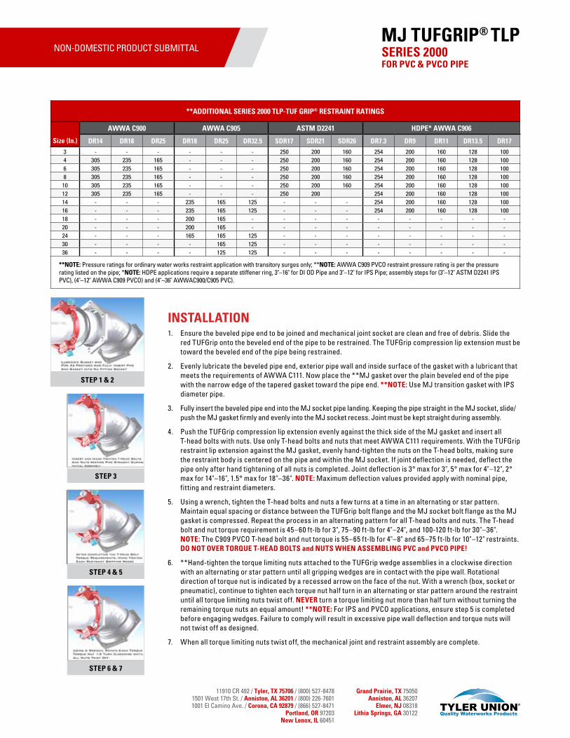
11910 CR 492 / Tyler, TX 75706 / (800) 527-84781501 West 17th St. / Anniston, AL 36201 / (800) 226-76011001 El Camino Ave. / Corona, CA 92879 / (866) 527-8471
Portland, OR 97203New Lenox, IL 60451
Grand Prairie, TX 75050Anniston, AL 36207
Elmer, NJ 08318Lithia Springs, GA 30122
INSTALLATION1. Ensure the beveled pipe end to be joined and mechanical joint socket are clean and free of debris. Slide the
red TUFGrip onto the beveled end of the pipe to be restrained. The TUFGrip compression lip extension must be toward the beveled end of the pipe being restrained.
2. Evenly lubricate the beveled pipe end, exterior pipe wall and inside surface of the gasket with a lubricant that meets the requirements of AWWA C111. Now place the **MJ gasket over the plain beveled end of the pipe with the narrow edge of the tapered gasket toward the pipe end. **NOTE: Use MJ transition gasket with IPS diameter pipe.
3. Fully insert the beveled pipe end into the MJ socket pipe landing. Keeping the pipe straight in the MJ socket, slide/push the MJ gasket firmly and evenly into the MJ socket recess. Joint must be kept straight during assembly.
4. Push the TUFGrip compression lip extension evenly against the thick side of the MJ gasket and insert all T-head bolts with nuts. Use only T-head bolts and nuts that meet AWWA C111 requirements. With the TUFGrip restraint lip extension against the MJ gasket, evenly hand-tighten the nuts on the T-head bolts, making sure the restraint body is centered on the pipe and within the MJ socket. If joint deflection is needed, deflect the pipe only after hand tightening of all nuts is completed. Joint deflection is 3° max for 3", 5° max for 4"–12", 2° max for 14"–16", 1.5° max for 18"–36". NOTE: Maximum deflection values provided apply with nominal pipe, fitting and restraint diameters.
5. Using a wrench, tighten the T-head bolts and nuts a few turns at a time in an alternating or star pattern. Maintain equal spacing or distance between the TUFGrip bolt flange and the MJ socket bolt flange as the MJ gasket is compressed. Repeat the process in an alternating pattern for all T-head bolts and nuts. The T-head bolt and nut torque requirement is 45–60 ft-lb for 3", 75–90 ft-lb for 4"–24", and 100-120 ft-lb for 30"–36". NOTE: The C909 PVCO T-head bolt and nut torque is 55–65 ft-lb for 4"–8" and 65–75 ft-lb for 10"–12" restraints. DO NOT OVER TORQUE T-HEAD BOLTS and NUTS WHEN ASSEMBLING PVC and PVCO PIPE!
6. **Hand-tighten the torque limiting nuts attached to the TUFGrip wedge assemblies in a clockwise direction with an alternating or star pattern until all gripping wedges are in contact with the pipe wall. Rotational direction of torque nut is indicated by a recessed arrow on the face of the nut. With a wrench (box, socket or pneumatic), continue to tighten each torque nut half turn in an alternating or star pattern around the restraint until all torque limiting nuts twist off. NEVER turn a torque limiting nut more than half turn without turning the remaining torque nuts an equal amount! **NOTE: For IPS and PVCO applications, ensure step 5 is completed before engaging wedges. Failure to comply will result in excessive pipe wall deflection and torque nuts will not twist off as designed.
7. When all torque limiting nuts twist off, the mechanical joint and restraint assembly are complete.
**ADDITIONAL SERIES 2000 TLP-TUF GRIP® RESTRAINT RATINGS
Size (In.)
AWWA C900 AWWA C905 ASTM D2241 HDPE* AWWA C906
DR14 DR18 DR25 DR18 DR25 DR32.5 SDR17 SDR21 SDR26 DR7.3 DR9 DR11 DR13.5 DR17
3 - - - - - - 250 200 160 254 200 160 128 1004 305 235 165 - - - 250 200 160 254 200 160 128 1006 305 235 165 - - - 250 200 160 254 200 160 128 1008 305 235 165 - - - 250 200 160 254 200 160 128 100
10 305 235 165 - - - 250 200 160 254 200 160 128 10012 305 235 165 - - - 250 200 254 200 160 128 10014 - - - 235 165 125 - - - 254 200 160 128 10016 - - - 235 165 125 - - - 254 200 160 128 10018 - - - 200 165 - - - - - - - - -20 - - - 200 165 - - - - - - - - -24 - - - 165 165 125 - - - - - - - -30 - - - - 165 125 - - - - - - - -36 - - - - 125 125 - - - - - - - -
**NOTE: Pressure ratings for ordinary water works restraint application with transitory surges only; **NOTE: AWWA C909 PVCO restraint pressure rating is per the pressure rating listed on the pipe; *NOTE: HDPE applications require a separate stiffener ring, 3"–16" for DI OD Pipe and 3"–12" for IPS Pipe; assembly steps for (3"–12" ASTM D2241 IPS PVC), (4"–12" AWWA C909 PVCO) and (4"–36" AWWAC900/C905 PVC).
SERIES 2000 FOR PVC & PVCO PIPE
MJ TUFGRIP® TLP
STEP 1 & 2
STEP 3
STEP 4 & 5
STEP 6 & 7
NON-DOMESTIC PRODUCT SUBMITTAL
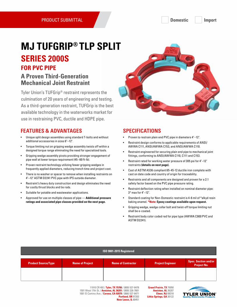
11910 CR 492 / Tyler, TX 75706 / (800) 527-84781501 West 17th St. / Anniston, AL 36201 / (800) 226-76011001 El Camino Ave. / Corona, CA 92879 / (866) 527-8471
Portland, OR 97203New Lenox, IL 60451
Grand Prairie, TX 75050Anniston, AL 36207
Elmer, NJ 08318Lithia Springs, GA 30122
SPECIFICATIONS• Proven to restrain plain end PVC pipe in diameters 4"–12".
• Restraint design conforms to applicable requirements of ANSI/AWWA C111, ANSI/AWWA C153, and ANSI/AWWA C110.
• Restraint engineered for securing plain end pipe to mechanical joint fittings, conforming to ANSI/AWWA C110, C111 and C153.
• Restraint rated for working water pressure of 305 psi for 4"–12" restraints (details on next page).
• Cast of ASTM A536 compliant 65-45-12 ductile iron complete with cast on date code and country of origin for traceability.
• Restraints and all components are designed and proven for a 2:1 safety factor based on the PVC pipe pressure rating.
• Restraint deflection rating when installed on nominal diameter pipe: 3° max for 4"–12".
• Standard coating for Non-Domestic restraint is 4-6 mil of *alkyd resin baking enamel. *Note: Epoxy coatings available upon request.
• Gripping wedge, wedge collar bolt and twist-off torque limiting nut shall be e-coated.
• Restraint body color coded red for pipe type (AWWA C900 PVC and ASTM D2241).
FEATURES & ADVANTAGES• Unique split design assembles using standard T-bolts and without
additional accessories in sizes 6"–12".
• Torque limiting nut on gripping wedge assembly twists off within a designed torque range eliminating the need for specialized tools.
• Gripping wedge assembly pivots providing stronger engagement of pipe wall at lower torque requirement (45–60 ft-lb).
• Proven restraint technology utilizing fewer gripping wedges in frequently applied diameters, reducing trench time and project cost.
• There is no washer or spacer to remove when installing restraints on 4"–12" ASTM D2241 PVC pipe with IPS outside diameter.
• Restraint’s heavy duty construction and design eliminates the need for costly thrust blocks and tie rods.
• Suitable for potable and wastewater applications.
• Approved for use on multiple classes of pipe — Additional pressure ratings and associated pipe classes provided on the next page.
PRODUCT SUBMITTAL
Product Source/Type Name of Project Name of Contractor Project EngineerSpec. Section and/or
Project No.
ISO 9001-2015 Registered
SERIES 2000S FOR PVC PIPEA Proven Third-Generation Mechanical Joint Restraint
MJ TUFGRIP® TLP SPLIT
Tyler Union’s TUFGrip® restraint represents the culmination of 20 years of engineering and testing. As a third-generation restraint, TUFGrip is the best available technology in the waterworks market for use in restraining PVC, ductile and HDPE pipe.
Domestic Import
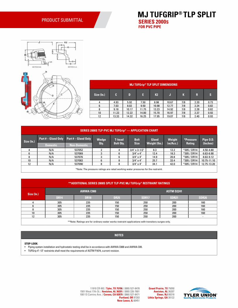
11910 CR 492 / Tyler, TX 75706 / (800) 527-84781501 West 17th St. / Anniston, AL 36201 / (800) 226-76011001 El Camino Ave. / Corona, CA 92879 / (866) 527-8471
Portland, OR 97203New Lenox, IL 60451
Grand Prairie, TX 75050Anniston, AL 36207
Elmer, NJ 08318Lithia Springs, GA 30122
PRODUCT SUBMITTAL
MJ TUFGrip® TLP SPLIT DIMENSIONS
Size (In.) C D E K2 J K R S
4 4.93 5.92 7.50 8.98 10.67 7/8 2.20 0.736 7.03 8.02 9.50 10.98 12.77 7/8 2.24 0.828 9.18 10.17 11.75 13.23 14.92 7/8 2.28 0.82
10 11.23 12.22 14.00 15.70 16.97 7/8 2.37 0.9312 13.33 14.32 16.25 17.95 19.07 7/8 2.40 0.93
NOTES
STOP-LOOK:• Piping system installation and hydrostatic testing shall be in accordance with AWWA C600 and AWWA C65.• TUFGrip 4"–12" restraints shall meet the requirements of ASTM F1674, current revision.
SERIES 2000SFOR PVC PIPE
MJ TUFGRIP® TLP SPLIT
SERIES 2000S TLP-PVC MJ TUFGrip® — APPLICATION CHART
Size (In.)Part # – Gland Only Part # – Gland Only Wedge
Qty.T-head
Bolt Qty.Bolt Size
Gland Weight (lbs.)
Weight(w/Acc.)
*Pressure Rating
Pipe O.D. (Inches)Domestic Non-Domestic
4 N/A 537052 2 4 3/4" x 3-1/2" 8.3 12.2 *305 / DR14 4.50-4.806 N/A 537069 3 6 3/4" x 4" 12.4 18.3 *305 / DR14 6.63-6.908 N/A 537076 3 6 3/4" x 4" 14.9 20.8 *305 / DR14 8.63-9.12
10 N/A 537083 6 8 3/4" x 4" 25.7 33.4 *305 / DR14 10.75-11.1012 N/A 537090 8 8 3/4" x 4" 34.1 42.0 *305 / DR14 12.75-13.20
*Note: The pressure ratings are rated working water pressures for the restraint.
**ADDITIONAL SERIES 2000S SPLIT TLP-PVC MJ TUFGrip® RESTRAINT RATINGS
Size (In.)AWWA C900 ASTM D2241
DR14 DR18 DR25 SDR17 SDR21 SDR26
4 305 235 150 250 200 1606 305 235 150 250 200 1608 305 235 150 250 200 160
10 305 235 150 250 200 16012 305 235 150 250 200 -
**Note: Ratings are for ordinary water works restraint applications with transitory surges only.
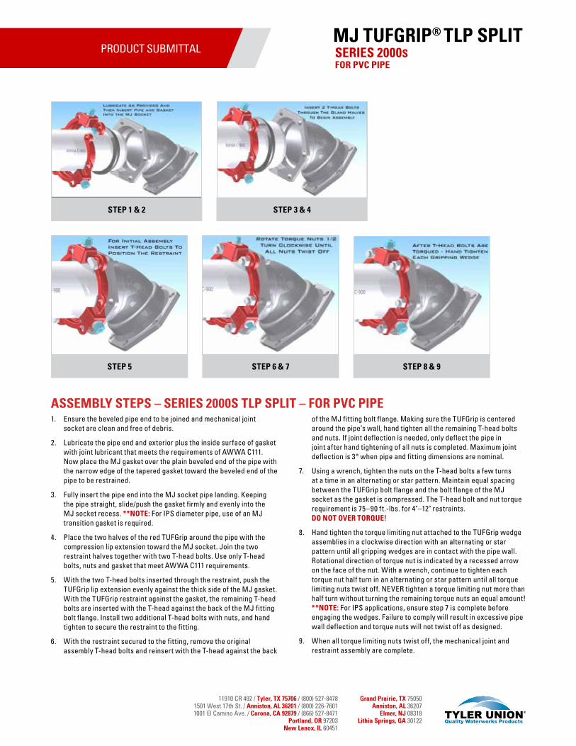
11910 CR 492 / Tyler, TX 75706 / (800) 527-84781501 West 17th St. / Anniston, AL 36201 / (800) 226-76011001 El Camino Ave. / Corona, CA 92879 / (866) 527-8471
Portland, OR 97203New Lenox, IL 60451
Grand Prairie, TX 75050Anniston, AL 36207
Elmer, NJ 08318Lithia Springs, GA 30122
PRODUCT SUBMITTAL
ASSEMBLY STEPS – SERIES 2000S TLP SPLIT – FOR PVC PIPE1. Ensure the beveled pipe end to be joined and mechanical joint
socket are clean and free of debris.
2. Lubricate the pipe end and exterior plus the inside surface of gasket with joint lubricant that meets the requirements of AWWA C111. Now place the MJ gasket over the plain beveled end of the pipe with the narrow edge of the tapered gasket toward the beveled end of the pipe to be restrained.
3. Fully insert the pipe end into the MJ socket pipe landing. Keeping the pipe straight, slide/push the gasket firmly and evenly into the MJ socket recess. **NOTE: For IPS diameter pipe, use of an MJ transition gasket is required.
4. Place the two halves of the red TUFGrip around the pipe with the compression lip extension toward the MJ socket. Join the two restraint halves together with two T-head bolts. Use only T-head bolts, nuts and gasket that meet AWWA C111 requirements.
5. With the two T-head bolts inserted through the restraint, push the TUFGrip lip extension evenly against the thick side of the MJ gasket. With the TUFGrip restraint against the gasket, the remaining T-head bolts are inserted with the T-head against the back of the MJ fitting bolt flange. Install two additional T-head bolts with nuts, and hand tighten to secure the restraint to the fitting.
6. With the restraint secured to the fitting, remove the original assembly T-head bolts and reinsert with the T-head against the back
of the MJ fitting bolt flange. Making sure the TUFGrip is centered around the pipe’s wall, hand tighten all the remaining T-head bolts and nuts. If joint deflection is needed, only deflect the pipe in joint after hand tightening of all nuts is completed. Maximum joint deflection is 3° when pipe and fitting dimensions are nominal.
7. Using a wrench, tighten the nuts on the T-head bolts a few turns at a time in an alternating or star pattern. Maintain equal spacing between the TUFGrip bolt flange and the bolt flange of the MJ socket as the gasket is compressed. The T-head bolt and nut torque requirement is 75–90 ft.-lbs. for 4"–12" restraints. DO NOT OVER TORQUE!
8. Hand tighten the torque limiting nut attached to the TUFGrip wedge assemblies in a clockwise direction with an alternating or star pattern until all gripping wedges are in contact with the pipe wall. Rotational direction of torque nut is indicated by a recessed arrow on the face of the nut. With a wrench, continue to tighten each torque nut half turn in an alternating or star pattern until all torque limiting nuts twist off. NEVER tighten a torque limiting nut more than half turn without turning the remaining torque nuts an equal amount! **NOTE: For IPS applications, ensure step 7 is complete before engaging the wedges. Failure to comply will result in excessive pipe wall deflection and torque nuts will not twist off as designed.
9. When all torque limiting nuts twist off, the mechanical joint and restraint assembly are complete.
SERIES 2000SFOR PVC PIPE
MJ TUFGRIP® TLP SPLIT
STEP 1 & 2 STEP 3 & 4
STEP 5 STEP 8 & 9STEP 6 & 7
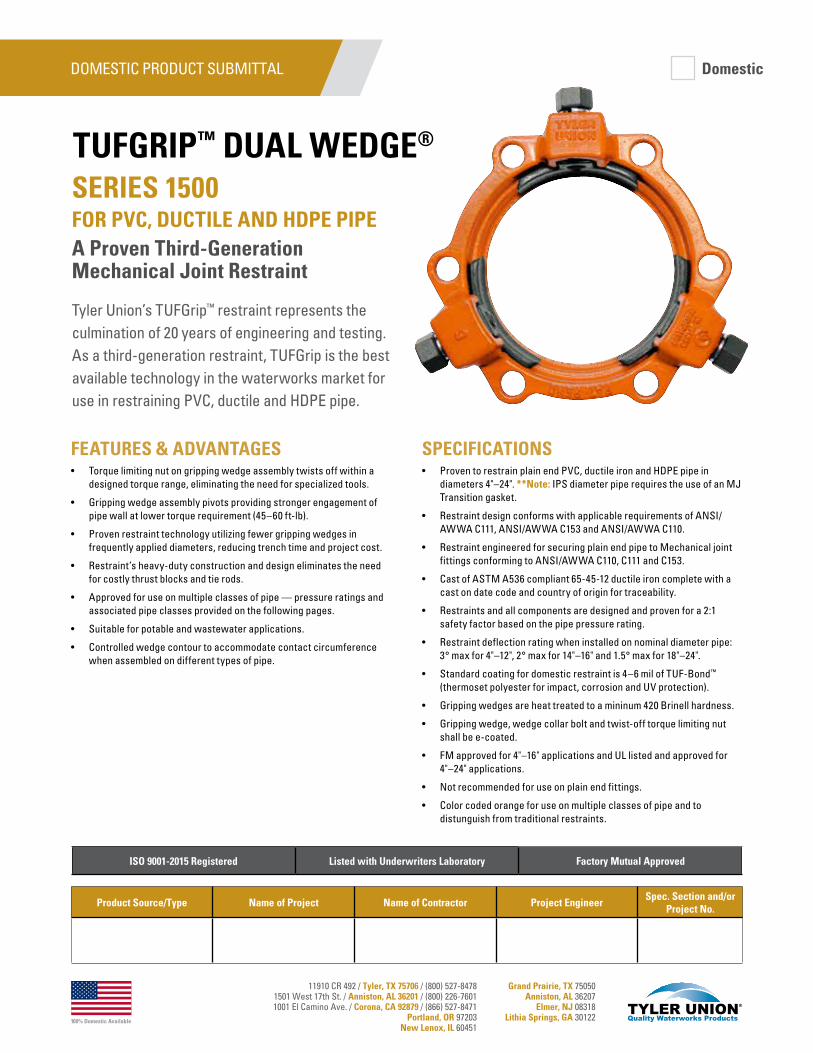
100% Domestic Available
11910 CR 492 / Tyler, TX 75706 / (800) 527-84781501 West 17th St. / Anniston, AL 36201 / (800) 226-76011001 El Camino Ave. / Corona, CA 92879 / (866) 527-8471
Portland, OR 97203New Lenox, IL 60451
Grand Prairie, TX 75050Anniston, AL 36207
Elmer, NJ 08318Lithia Springs, GA 30122
Tyler Union’s TUFGrip™ restraint represents the culmination of 20 years of engineering and testing. As a third-generation restraint, TUFGrip is the best available technology in the waterworks market for use in restraining PVC, ductile and HDPE pipe.
SPECIFICATIONS• Proven to restrain plain end PVC, ductile iron and HDPE pipe in
diameters 4"–24". **Note: IPS diameter pipe requires the use of an MJ Transition gasket.
• Restraint design conforms with applicable requirements of ANSI/AWWA C111, ANSI/AWWA C153 and ANSI/AWWA C110.
• Restraint engineered for securing plain end pipe to Mechanical joint fittings conforming to ANSI/AWWA C110, C111 and C153.
• Cast of ASTM A536 compliant 65-45-12 ductile iron complete with a cast on date code and country of origin for traceability.
• Restraints and all components are designed and proven for a 2:1 safety factor based on the pipe pressure rating.
• Restraint deflection rating when installed on nominal diameter pipe: 3° max for 4"–12", 2° max for 14"–16" and 1.5° max for 18"–24".
• Standard coating for domestic restraint is 4–6 mil of TUF-Bond™ (thermoset polyester for impact, corrosion and UV protection).
• Gripping wedges are heat treated to a mininum 420 Brinell hardness.
• Gripping wedge, wedge collar bolt and twist-off torque limiting nut shall be e-coated.
• FM approved for 4"–16" applications and UL listed and approved for 4"–24" applications.
• Not recommended for use on plain end fittings.
• Color coded orange for use on multiple classes of pipe and to distunguish from traditional restraints.
FEATURES & ADVANTAGES• Torque limiting nut on gripping wedge assembly twists off within a
designed torque range, eliminating the need for specialized tools.
• Gripping wedge assembly pivots providing stronger engagement of pipe wall at lower torque requirement (45–60 ft-lb).
• Proven restraint technology utilizing fewer gripping wedges in frequently applied diameters, reducing trench time and project cost.
• Restraint’s heavy-duty construction and design eliminates the need for costly thrust blocks and tie rods.
• Approved for use on multiple classes of pipe — pressure ratings and associated pipe classes provided on the following pages.
• Suitable for potable and wastewater applications.
• Controlled wedge contour to accommodate contact circumference when assembled on different types of pipe.
SERIES 1500 FOR PVC, DUCTILE AND HDPE PIPEA Proven Third-Generation Mechanical Joint Restraint
TUFGRIP™ DUAL WEDGE®
DOMESTIC PRODUCT SUBMITTAL
Product Source/Type Name of Project Name of Contractor Project EngineerSpec. Section and/or
Project No.
ISO 9001-2015 Registered Listed with Underwriters Laboratory Factory Mutual Approved
Domestic
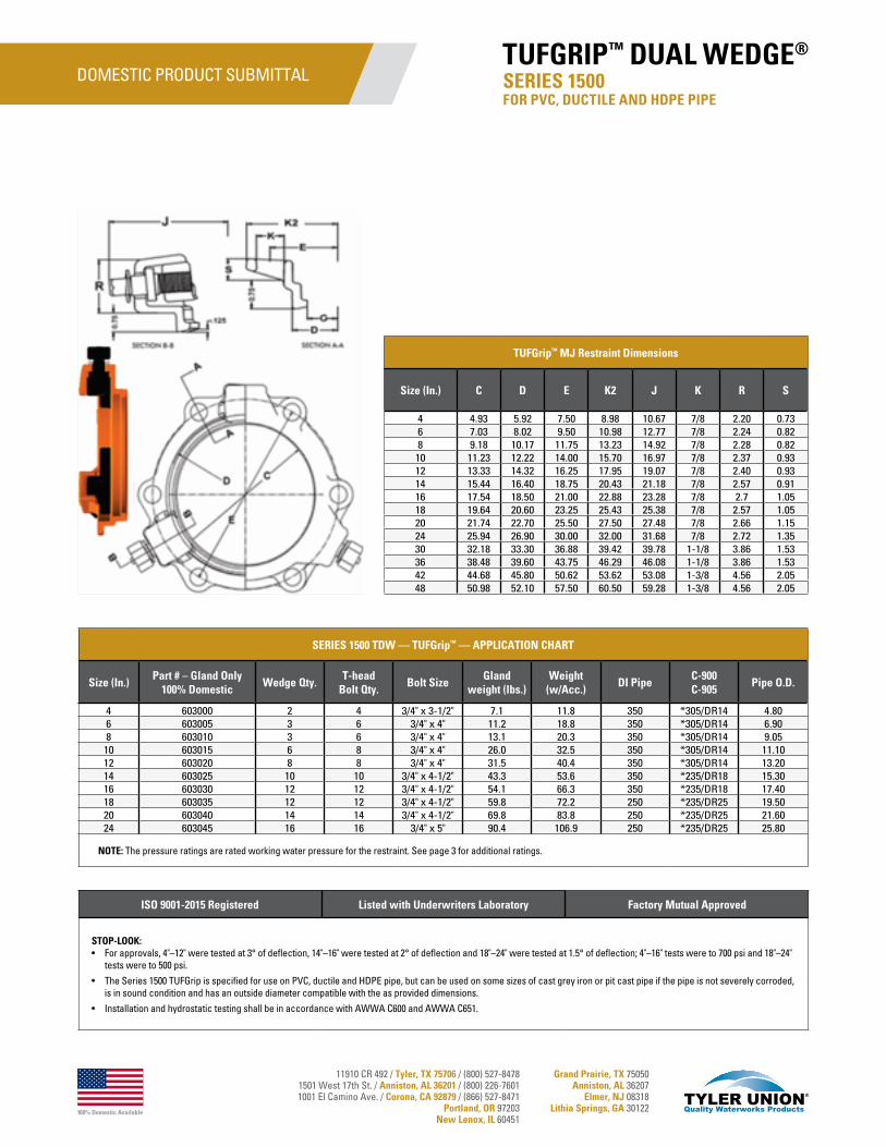
100% Domestic Available
11910 CR 492 / Tyler, TX 75706 / (800) 527-84781501 West 17th St. / Anniston, AL 36201 / (800) 226-76011001 El Camino Ave. / Corona, CA 92879 / (866) 527-8471
Portland, OR 97203New Lenox, IL 60451
Grand Prairie, TX 75050Anniston, AL 36207
Elmer, NJ 08318Lithia Springs, GA 30122
DOMESTIC PRODUCT SUBMITTAL
SERIES 1500 TDW — TUFGrip™ — APPLICATION CHART
Size (In.)Part # – Gland Only
100% DomesticWedge Qty.
T-head Bolt Qty.
Bolt SizeGland
weight (lbs.)Weight
(w/Acc.)DI Pipe
C-900C-905
Pipe O.D.
4 603000 2 4 3/4" x 3-1/2" 7.1 11.8 350 *305/DR14 4.806 603005 3 6 3/4" x 4" 11.2 18.8 350 *305/DR14 6.908 603010 3 6 3/4" x 4" 13.1 20.3 350 *305/DR14 9.0510 603015 6 8 3/4" x 4" 26.0 32.5 350 *305/DR14 11.1012 603020 8 8 3/4" x 4" 31.5 40.4 350 *305/DR14 13.2014 603025 10 10 3/4" x 4-1/2" 43.3 53.6 350 *235/DR18 15.3016 603030 12 12 3/4" x 4-1/2" 54.1 66.3 350 *235/DR18 17.4018 603035 12 12 3/4" x 4-1/2" 59.8 72.2 250 *235/DR25 19.5020 603040 14 14 3/4" x 4-1/2" 69.8 83.8 250 *235/DR25 21.6024 603045 16 16 3/4" x 5" 90.4 106.9 250 *235/DR25 25.80
NOTE: The pressure ratings are rated working water pressure for the restraint. See page 3 for additional ratings.
TUFGrip™ MJ Restraint Dimensions
Size (In.) C D E K2 J K R S
4 4.93 5.92 7.50 8.98 10.67 7/8 2.20 0.736 7.03 8.02 9.50 10.98 12.77 7/8 2.24 0.828 9.18 10.17 11.75 13.23 14.92 7/8 2.28 0.82
10 11.23 12.22 14.00 15.70 16.97 7/8 2.37 0.9312 13.33 14.32 16.25 17.95 19.07 7/8 2.40 0.9314 15.44 16.40 18.75 20.43 21.18 7/8 2.57 0.9116 17.54 18.50 21.00 22.88 23.28 7/8 2.7 1.0518 19.64 20.60 23.25 25.43 25.38 7/8 2.57 1.0520 21.74 22.70 25.50 27.50 27.48 7/8 2.66 1.1524 25.94 26.90 30.00 32.00 31.68 7/8 2.72 1.3530 32.18 33.30 36.88 39.42 39.78 1-1/8 3.86 1.5336 38.48 39.60 43.75 46.29 46.08 1-1/8 3.86 1.5342 44.68 45.80 50.62 53.62 53.08 1-3/8 4.56 2.0548 50.98 52.10 57.50 60.50 59.28 1-3/8 4.56 2.05
ISO 9001-2015 Registered Listed with Underwriters Laboratory Factory Mutual Approved
STOP-LOOK:• For approvals, 4"–12" were tested at 3° of deflection, 14"–16" were tested at 2° of deflection and 18"–24" were tested at 1.5° of deflection; 4"–16" tests were to 700 psi and 18"–24"
tests were to 500 psi.
• The Series 1500 TUFGrip is specified for use on PVC, ductile and HDPE pipe, but can be used on some sizes of cast grey iron or pit cast pipe if the pipe is not severely corroded, is in sound condition and has an outside diameter compatible with the as provided dimensions.
• Installation and hydrostatic testing shall be in accordance with AWWA C600 and AWWA C651.
SERIES 1500 FOR PVC, DUCTILE AND HDPE PIPE
TUFGRIP™ DUAL WEDGE®
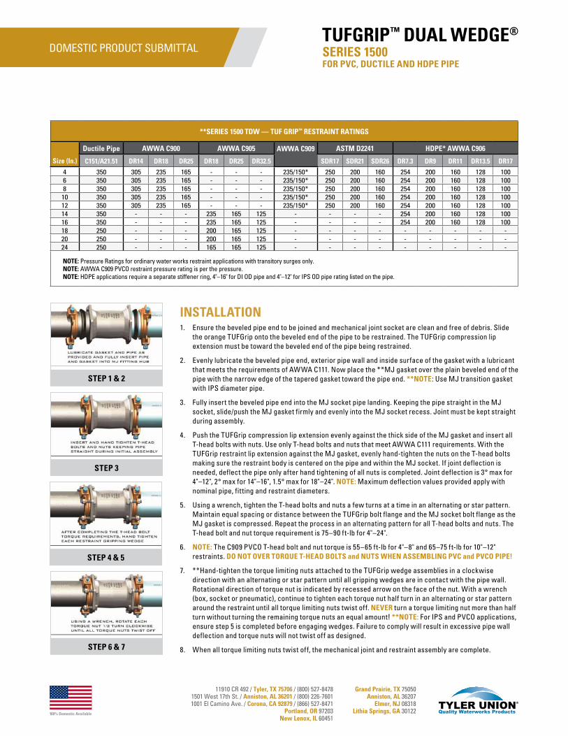
100% Domestic Available
11910 CR 492 / Tyler, TX 75706 / (800) 527-84781501 West 17th St. / Anniston, AL 36201 / (800) 226-76011001 El Camino Ave. / Corona, CA 92879 / (866) 527-8471
Portland, OR 97203New Lenox, IL 60451
Grand Prairie, TX 75050Anniston, AL 36207
Elmer, NJ 08318Lithia Springs, GA 30122
DOMESTIC PRODUCT SUBMITTAL
INSTALLATION1. Ensure the beveled pipe end to be joined and mechanical joint socket are clean and free of debris. Slide
the orange TUFGrip onto the beveled end of the pipe to be restrained. The TUFGrip compression lip extension must be toward the beveled end of the pipe being restrained.
2. Evenly lubricate the beveled pipe end, exterior pipe wall and inside surface of the gasket with a lubricant that meets the requirements of AWWA C111. Now place the **MJ gasket over the plain beveled end of the pipe with the narrow edge of the tapered gasket toward the pipe end. **NOTE: Use MJ transition gasket with IPS diameter pipe.
3. Fully insert the beveled pipe end into the MJ socket pipe landing. Keeping the pipe straight in the MJ socket, slide/push the MJ gasket firmly and evenly into the MJ socket recess. Joint must be kept straight during assembly.
4. Push the TUFGrip compression lip extension evenly against the thick side of the MJ gasket and insert all T-head bolts with nuts. Use only T-head bolts and nuts that meet AWWA C111 requirements. With the TUFGrip restraint lip extension against the MJ gasket, evenly hand-tighten the nuts on the T-head bolts making sure the restraint body is centered on the pipe and within the MJ socket. If joint deflection is needed, deflect the pipe only after hand tightening of all nuts is completed. Joint deflection is 3° max for 4"–12", 2° max for 14"–16", 1.5° max for 18"–24". NOTE: Maximum deflection values provided apply with nominal pipe, fitting and restraint diameters.
5. Using a wrench, tighten the T-head bolts and nuts a few turns at a time in an alternating or star pattern. Maintain equal spacing or distance between the TUFGrip bolt flange and the MJ socket bolt flange as the MJ gasket is compressed. Repeat the process in an alternating pattern for all T-head bolts and nuts. The T-head bolt and nut torque requirement is 75–90 ft-lb for 4"–24".
6. NOTE: The C909 PVCO T-head bolt and nut torque is 55–65 ft-lb for 4"–8" and 65–75 ft-lb for 10"–12" restraints. DO NOT OVER TORQUE T-HEAD BOLTS and NUTS WHEN ASSEMBLING PVC and PVCO PIPE!
7. **Hand-tighten the torque limiting nuts attached to the TUFGrip wedge assemblies in a clockwise direction with an alternating or star pattern until all gripping wedges are in contact with the pipe wall. Rotational direction of torque nut is indicated by recessed arrow on the face of the nut. With a wrench (box, socket or pneumatic), continue to tighten each torque nut half turn in an alternating or star pattern around the restraint until all torque limiting nuts twist off. NEVER turn a torque limiting nut more than half turn without turning the remaining torque nuts an equal amount! **NOTE: For IPS and PVCO applications, ensure step 5 is completed before engaging wedges. Failure to comply will result in excessive pipe wall deflection and torque nuts will not twist off as designed.
8. When all torque limiting nuts twist off, the mechanical joint and restraint assembly are complete.
**SERIES 1500 TDW — TUF GRIP™ RESTRAINT RATINGS
Size (In.)
Ductile Pipe AWWA C900 AWWA C905 AWWA C909 ASTM D2241 HDPE* AWWA C906
C151/A21.51 DR14 DR18 DR25 DR18 DR25 DR32.5 SDR17 SDR21 SDR26 DR7.3 DR9 DR11 DR13.5 DR17
4 350 305 235 165 - - - 235/150* 250 200 160 254 200 160 128 1006 350 305 235 165 - - - 235/150* 250 200 160 254 200 160 128 1008 350 305 235 165 - - - 235/150* 250 200 160 254 200 160 128 100
10 350 305 235 165 - - - 235/150* 250 200 160 254 200 160 128 10012 350 305 235 165 - - - 235/150* 250 200 160 254 200 160 128 10014 350 - - - 235 165 125 - - - - 254 200 160 128 10016 350 - - - 235 165 125 - - - - 254 200 160 128 10018 250 - - - 200 165 125 - - - - - - - - -20 250 - - - 200 165 125 - - - - - - - - -24 250 - - - 165 165 125 - - - - - - - - -
NOTE: Pressure Ratings for ordinary water works restraint applications with transitory surges only. NOTE: AWWA C909 PVCO restraint pressure rating is per the pressure.NOTE: HDPE applications require a separate stiffener ring, 4"–16" for DI OD pipe and 4"–12" for IPS OD pipe rating listed on the pipe.
STEP 1 & 2
STEP 3
STEP 4 & 5
STEP 6 & 7
SERIES 1500 FOR PVC, DUCTILE AND HDPE PIPE
TUFGRIP™ DUAL WEDGE®
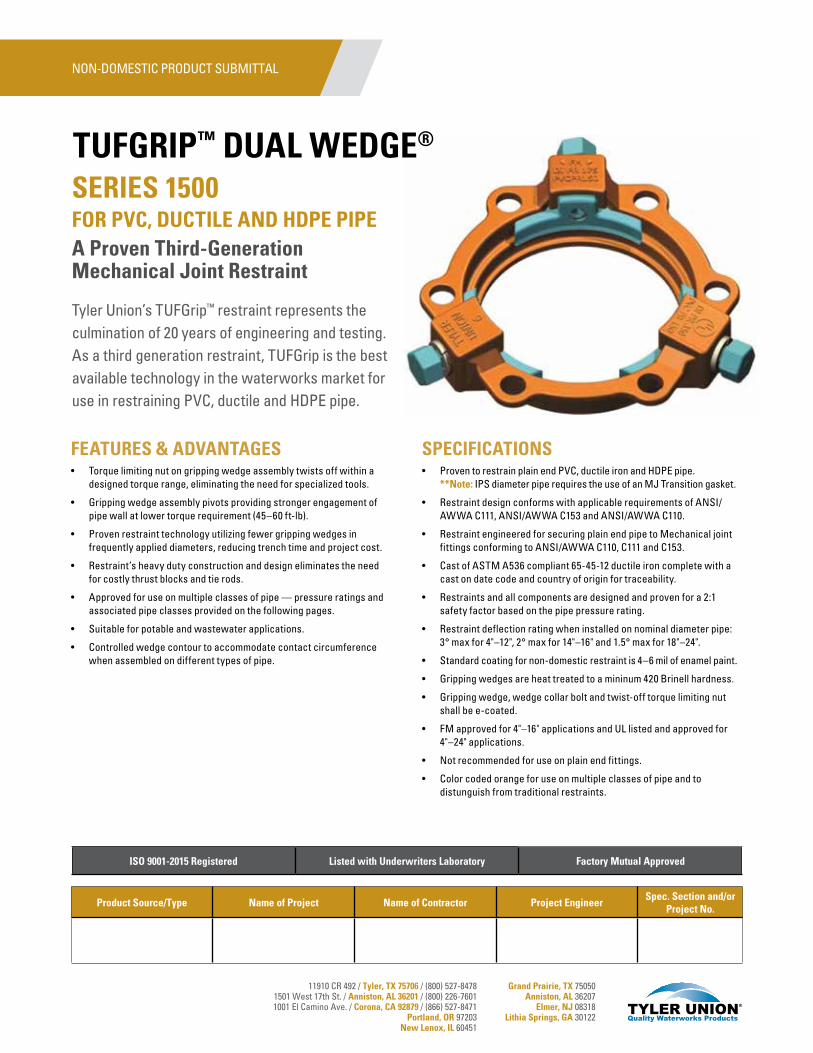
11910 CR 492 / Tyler, TX 75706 / (800) 527-84781501 West 17th St. / Anniston, AL 36201 / (800) 226-76011001 El Camino Ave. / Corona, CA 92879 / (866) 527-8471
Portland, OR 97203New Lenox, IL 60451
Grand Prairie, TX 75050Anniston, AL 36207
Elmer, NJ 08318Lithia Springs, GA 30122
Tyler Union’s TUFGrip™ restraint represents the culmination of 20 years of engineering and testing. As a third generation restraint, TUFGrip is the best available technology in the waterworks market for use in restraining PVC, ductile and HDPE pipe.
SPECIFICATIONS• Proven to restrain plain end PVC, ductile iron and HDPE pipe.
**Note: IPS diameter pipe requires the use of an MJ Transition gasket.
• Restraint design conforms with applicable requirements of ANSI/AWWA C111, ANSI/AWWA C153 and ANSI/AWWA C110.
• Restraint engineered for securing plain end pipe to Mechanical joint fittings conforming to ANSI/AWWA C110, C111 and C153.
• Cast of ASTM A536 compliant 65-45-12 ductile iron complete with a cast on date code and country of origin for traceability.
• Restraints and all components are designed and proven for a 2:1 safety factor based on the pipe pressure rating.
• Restraint deflection rating when installed on nominal diameter pipe: 3° max for 4"–12", 2° max for 14"–16" and 1.5° max for 18"–24".
• Standard coating for non-domestic restraint is 4–6 mil of enamel paint.
• Gripping wedges are heat treated to a mininum 420 Brinell hardness.
• Gripping wedge, wedge collar bolt and twist-off torque limiting nut shall be e-coated.
• FM approved for 4"–16" applications and UL listed and approved for 4"–24" applications.
• Not recommended for use on plain end fittings.
• Color coded orange for use on multiple classes of pipe and to distunguish from traditional restraints.
FEATURES & ADVANTAGES• Torque limiting nut on gripping wedge assembly twists off within a
designed torque range, eliminating the need for specialized tools.
• Gripping wedge assembly pivots providing stronger engagement of pipe wall at lower torque requirement (45–60 ft-lb).
• Proven restraint technology utilizing fewer gripping wedges in frequently applied diameters, reducing trench time and project cost.
• Restraint’s heavy duty construction and design eliminates the need for costly thrust blocks and tie rods.
• Approved for use on multiple classes of pipe — pressure ratings and associated pipe classes provided on the following pages.
• Suitable for potable and wastewater applications.
• Controlled wedge contour to accommodate contact circumference when assembled on different types of pipe.
SERIES 1500 FOR PVC, DUCTILE AND HDPE PIPEA Proven Third-Generation Mechanical Joint Restraint
TUFGRIP™ DUAL WEDGE®
Product Source/Type Name of Project Name of Contractor Project EngineerSpec. Section and/or
Project No.
ISO 9001-2015 Registered Listed with Underwriters Laboratory Factory Mutual Approved
NON-DOMESTIC PRODUCT SUBMITTAL
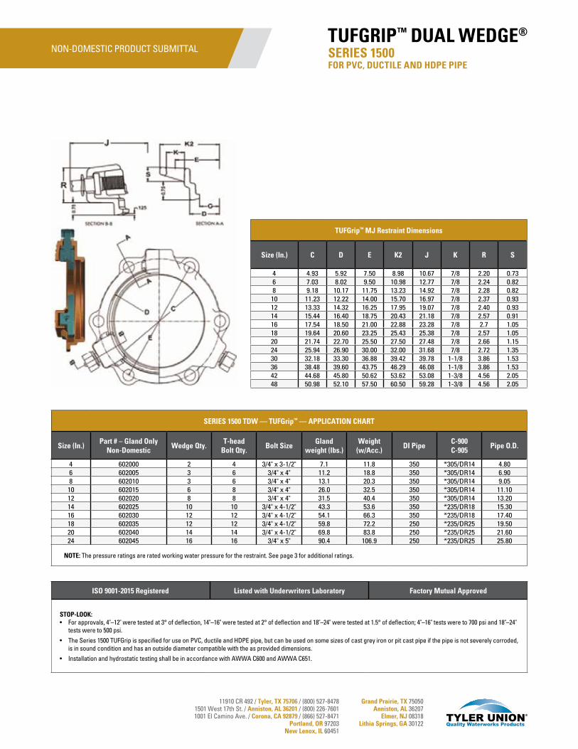
11910 CR 492 / Tyler, TX 75706 / (800) 527-84781501 West 17th St. / Anniston, AL 36201 / (800) 226-76011001 El Camino Ave. / Corona, CA 92879 / (866) 527-8471
Portland, OR 97203New Lenox, IL 60451
Grand Prairie, TX 75050Anniston, AL 36207
Elmer, NJ 08318Lithia Springs, GA 30122
SERIES 1500 TDW — TUFGrip™ — APPLICATION CHART
Size (In.)Part # – Gland Only
Non-DomesticWedge Qty.
T-head Bolt Qty.
Bolt SizeGland
weight (lbs.)Weight
(w/Acc.)DI Pipe
C-900C-905
Pipe O.D.
4 602000 2 4 3/4" x 3-1/2" 7.1 11.8 350 *305/DR14 4.806 602005 3 6 3/4" x 4" 11.2 18.8 350 *305/DR14 6.908 602010 3 6 3/4" x 4" 13.1 20.3 350 *305/DR14 9.0510 602015 6 8 3/4" x 4" 26.0 32.5 350 *305/DR14 11.1012 602020 8 8 3/4" x 4" 31.5 40.4 350 *305/DR14 13.2014 602025 10 10 3/4" x 4-1/2" 43.3 53.6 350 *235/DR18 15.3016 602030 12 12 3/4" x 4-1/2" 54.1 66.3 350 *235/DR18 17.4018 602035 12 12 3/4" x 4-1/2" 59.8 72.2 250 *235/DR25 19.5020 602040 14 14 3/4" x 4-1/2" 69.8 83.8 250 *235/DR25 21.6024 602045 16 16 3/4" x 5" 90.4 106.9 250 *235/DR25 25.80
NOTE: The pressure ratings are rated working water pressure for the restraint. See page 3 for additional ratings.
TUFGrip™ MJ Restraint Dimensions
Size (In.) C D E K2 J K R S
4 4.93 5.92 7.50 8.98 10.67 7/8 2.20 0.736 7.03 8.02 9.50 10.98 12.77 7/8 2.24 0.828 9.18 10.17 11.75 13.23 14.92 7/8 2.28 0.82
10 11.23 12.22 14.00 15.70 16.97 7/8 2.37 0.9312 13.33 14.32 16.25 17.95 19.07 7/8 2.40 0.9314 15.44 16.40 18.75 20.43 21.18 7/8 2.57 0.9116 17.54 18.50 21.00 22.88 23.28 7/8 2.7 1.0518 19.64 20.60 23.25 25.43 25.38 7/8 2.57 1.0520 21.74 22.70 25.50 27.50 27.48 7/8 2.66 1.1524 25.94 26.90 30.00 32.00 31.68 7/8 2.72 1.3530 32.18 33.30 36.88 39.42 39.78 1-1/8 3.86 1.5336 38.48 39.60 43.75 46.29 46.08 1-1/8 3.86 1.5342 44.68 45.80 50.62 53.62 53.08 1-3/8 4.56 2.0548 50.98 52.10 57.50 60.50 59.28 1-3/8 4.56 2.05
ISO 9001-2015 Registered Listed with Underwriters Laboratory Factory Mutual Approved
STOP-LOOK:• For approvals, 4"–12" were tested at 3° of deflection, 14"–16" were tested at 2° of deflection and 18"–24" were tested at 1.5° of deflection; 4"–16" tests were to 700 psi and 18"–24"
tests were to 500 psi.
• The Series 1500 TUFGrip is specified for use on PVC, ductile and HDPE pipe, but can be used on some sizes of cast grey iron or pit cast pipe if the pipe is not severely corroded, is in sound condition and has an outside diameter compatible with the as provided dimensions.
• Installation and hydrostatic testing shall be in accordance with AWWA C600 and AWWA C651.
SERIES 1500 FOR PVC, DUCTILE AND HDPE PIPE
TUFGRIP™ DUAL WEDGE®NON-DOMESTIC PRODUCT SUBMITTAL
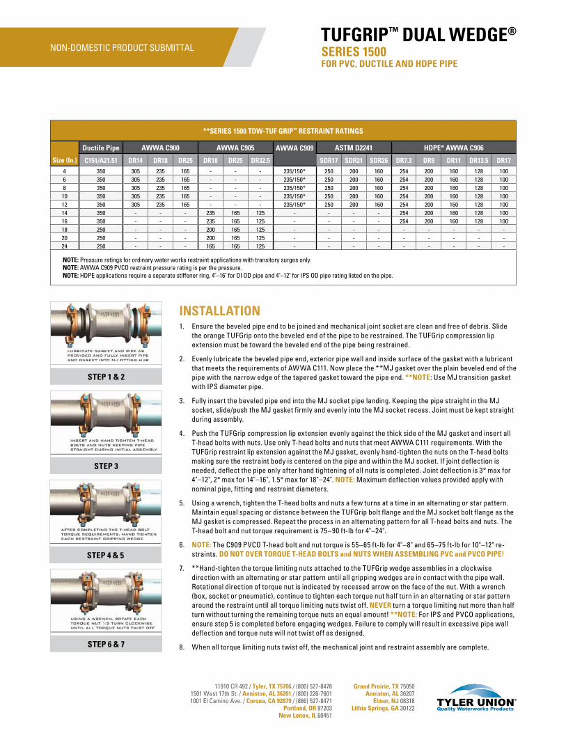
11910 CR 492 / Tyler, TX 75706 / (800) 527-84781501 West 17th St. / Anniston, AL 36201 / (800) 226-76011001 El Camino Ave. / Corona, CA 92879 / (866) 527-8471
Portland, OR 97203New Lenox, IL 60451
Grand Prairie, TX 75050Anniston, AL 36207
Elmer, NJ 08318Lithia Springs, GA 30122
INSTALLATION1. Ensure the beveled pipe end to be joined and mechanical joint socket are clean and free of debris. Slide
the orange TUFGrip onto the beveled end of the pipe to be restrained. The TUFGrip compression lip extension must be toward the beveled end of the pipe being restrained.
2. Evenly lubricate the beveled pipe end, exterior pipe wall and inside surface of the gasket with a lubricant that meets the requirements of AWWA C111. Now place the **MJ gasket over the plain beveled end of the pipe with the narrow edge of the tapered gasket toward the pipe end. **NOTE: Use MJ transition gasket with IPS diameter pipe.
3. Fully insert the beveled pipe end into the MJ socket pipe landing. Keeping the pipe straight in the MJ socket, slide/push the MJ gasket firmly and evenly into the MJ socket recess. Joint must be kept straight during assembly.
4. Push the TUFGrip compression lip extension evenly against the thick side of the MJ gasket and insert all T-head bolts with nuts. Use only T-head bolts and nuts that meet AWWA C111 requirements. With the TUFGrip restraint lip extension against the MJ gasket, evenly hand-tighten the nuts on the T-head bolts making sure the restraint body is centered on the pipe and within the MJ socket. If joint deflection is needed, deflect the pipe only after hand tightening of all nuts is completed. Joint deflection is 3° max for 4"–12", 2° max for 14"–16", 1.5° max for 18"–24". NOTE: Maximum deflection values provided apply with nominal pipe, fitting and restraint diameters.
5. Using a wrench, tighten the T-head bolts and nuts a few turns at a time in an alternating or star pattern. Maintain equal spacing or distance between the TUFGrip bolt flange and the MJ socket bolt flange as the MJ gasket is compressed. Repeat the process in an alternating pattern for all T-head bolts and nuts. The T-head bolt and nut torque requirement is 75–90 ft-lb for 4"–24".
6. NOTE: The C909 PVCO T-head bolt and nut torque is 55–65 ft-lb for 4"–8" and 65–75 ft-lb for 10"–12" re-straints. DO NOT OVER TORQUE T-HEAD BOLTS and NUTS WHEN ASSEMBLING PVC and PVCO PIPE!
7. **Hand-tighten the torque limiting nuts attached to the TUFGrip wedge assemblies in a clockwise direction with an alternating or star pattern until all gripping wedges are in contact with the pipe wall. Rotational direction of torque nut is indicated by recessed arrow on the face of the nut. With a wrench (box, socket or pneumatic), continue to tighten each torque nut half turn in an alternating or star pattern around the restraint until all torque limiting nuts twist off. NEVER turn a torque limiting nut more than half turn without turning the remaining torque nuts an equal amount! **NOTE: For IPS and PVCO applications, ensure step 5 is completed before engaging wedges. Failure to comply will result in excessive pipe wall deflection and torque nuts will not twist off as designed.
8. When all torque limiting nuts twist off, the mechanical joint and restraint assembly are complete.
**SERIES 1500 TDW-TUF GRIP™ RESTRAINT RATINGS
Size (In.)
Ductile Pipe AWWA C900 AWWA C905 AWWA C909 ASTM D2241 HDPE* AWWA C906
C151/A21.51 DR14 DR18 DR25 DR18 DR25 DR32.5 SDR17 SDR21 SDR26 DR7.3 DR9 DR11 DR13.5 DR17
4 350 305 235 165 - - - 235/150* 250 200 160 254 200 160 128 1006 350 305 235 165 - - - 235/150* 250 200 160 254 200 160 128 1008 350 305 235 165 - - - 235/150* 250 200 160 254 200 160 128 10010 350 305 235 165 - - - 235/150* 250 200 160 254 200 160 128 10012 350 305 235 165 - - - 235/150* 250 200 160 254 200 160 128 10014 350 - - - 235 165 125 - - - - 254 200 160 128 10016 350 - - - 235 165 125 - - - - 254 200 160 128 10018 250 - - - 200 165 125 - - - - - - - - -20 250 - - - 200 165 125 - - - - - - - - -24 250 - - - 165 165 125 - - - - - - - - -
NOTE: Pressure ratings for ordinary water works restraint applications with transitory surges only. NOTE: AWWA C909 PVCO restraint pressure rating is per the pressure.NOTE: HDPE applications require a separate stiffener ring, 4"–16" for DI OD pipe and 4"–12" for IPS OD pipe rating listed on the pipe.
STEP 1 & 2
STEP 3
STEP 4 & 5
STEP 6 & 7
SERIES 1500 FOR PVC, DUCTILE AND HDPE PIPE
TUFGRIP™ DUAL WEDGE®NON-DOMESTIC PRODUCT SUBMITTAL
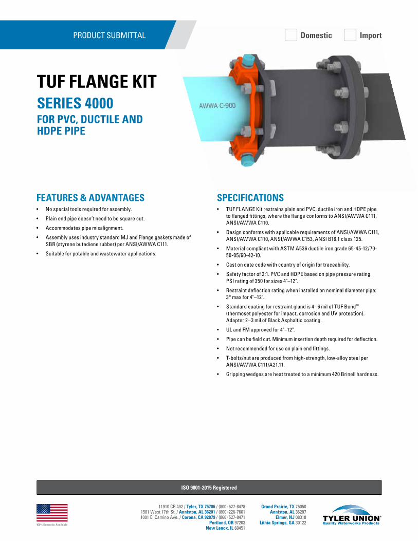
100% Domestic Available
11910 CR 492 / Tyler, TX 75706 / (800) 527-84781501 West 17th St. / Anniston, AL 36201 / (800) 226-76011001 El Camino Ave. / Corona, CA 92879 / (866) 527-8471
Portland, OR 97203New Lenox, IL 60451
Grand Prairie, TX 75050Anniston, AL 36207
Elmer, NJ 08318Lithia Springs, GA 30122
SPECIFICATIONS• TUF FLANGE Kit restrains plain end PVC, ductile iron and HDPE pipe
to flanged fittings, where the flange conforms to ANSI/AWWA C111, ANSI/AWWA C110.
• Design conforms with applicable requirements of ANSI/AWWA C111, ANSI/AWWA C110, ANSI/AWWA C153, ANSI B16.1 class 125.
• Material compliant with ASTM A536 ductile iron grade 65-45-12/70-50-05/60-42-10.
• Cast on date code with country of origin for traceability.
• Safety factor of 2:1. PVC and HDPE based on pipe pressure rating. PSI rating of 350 for sizes 4"–12".
• Restraint deflection rating when installed on nominal diameter pipe: 3° max for 4"–12".
• Standard coating for restraint gland is 4–6 mil of TUF Bond™ (thermoset polyester for impact, corrosion and UV protection). Adapter 2–3 mil of Black Asphaltic coating.
• UL and FM approved for 4"–12".
• Pipe can be field cut. Minimum insertion depth required for deflection.
• Not recommended for use on plain end fittings.
• T-bolts/nut are produced from high-strength, low-alloy steel per ANSI/AWWA C111/A21.11.
• Gripping wedges are heat treated to a minimum 420 Brinell hardness.
FEATURES & ADVANTAGES• No special tools required for assembly.
• Plain end pipe doesn’t need to be square cut.
• Accommodates pipe misalignment.
• Assembly uses industry standard MJ and Flange gaskets made of SBR (styrene butadiene rubber) per ANSI/AWWA C111.
• Suitable for potable and wastewater applications.
PRODUCT SUBMITTAL
ISO 9001-2015 Registered
SERIES 4000FOR PVC, DUCTILE AND HDPE PIPE
TUF FLANGE KIT
Domestic Import

100% Domestic Available
11910 CR 492 / Tyler, TX 75706 / (800) 527-84781501 West 17th St. / Anniston, AL 36201 / (800) 226-76011001 El Camino Ave. / Corona, CA 92879 / (866) 527-8471
Portland, OR 97203New Lenox, IL 60451
Grand Prairie, TX 75050Anniston, AL 36207
Elmer, NJ 08318Lithia Springs, GA 30122
PRODUCT SUBMITTAL
SERIES 4000 Dimensions and Application Chart
Size (Inches)
Pipe O.D. A B C E L L1T-head
Bolt Qty.Bolt Size
Weight (w/Acc.)
4 4.50–4.80 10.67 9.0 5.35 2.5 10.0 9.5 4 ¾" x 3-1/2" 456 6.63–6.90 12.77 11.0 7.45 2.5 10.0 9.5 6 ¾" x 4" 608 8.63–9.12 14.92 13.5 9.65 2.5 10.0 9.5 6 ¾" x 4" 75
10 10.75–11.10 16.97 16.0 11.81 2.5 10.0 9.5 8 ¾" x 4" 10312 12.75–13.20 19.07 19.0 13.89 2.5 10.0 9.5 8 ¾" x 4" 130
SERIES 4000 FOR PVC, DUCTILE AND HDPE PIPE
TUF FLANGE KIT
*SERIES 4000 TUF FLANGE™ Pressure Ratings
Size (In.)
Ductile Pipe AWWA C900 AWWA C909 HDPE** AWWA C906
C151/A21.51 DR14 DR18 DR25 DR7.3 DR9 DR11 DR13.5 DR17
4 350 305 235 165 235/150* 254 200 160 128 1006 350 305 235 165 235/150* 254 200 160 128 1008 350 305 235 165 235/150* 254 200 160 128 10010 350 305 235 165 235/150* 254 200 160 128 10012 350 305 235 165 235/150* 254 200 160 128 100
*Note: Pressure ratings for ordinary water works restraint application with transitory surges only.*Note: AWWA C909 PVCO restraint pressure rating is per the pressure rating listed on the pipe.
**Note: HDPE applications require a separate stiffener ring, 4"–12" for DI OD Pipe.
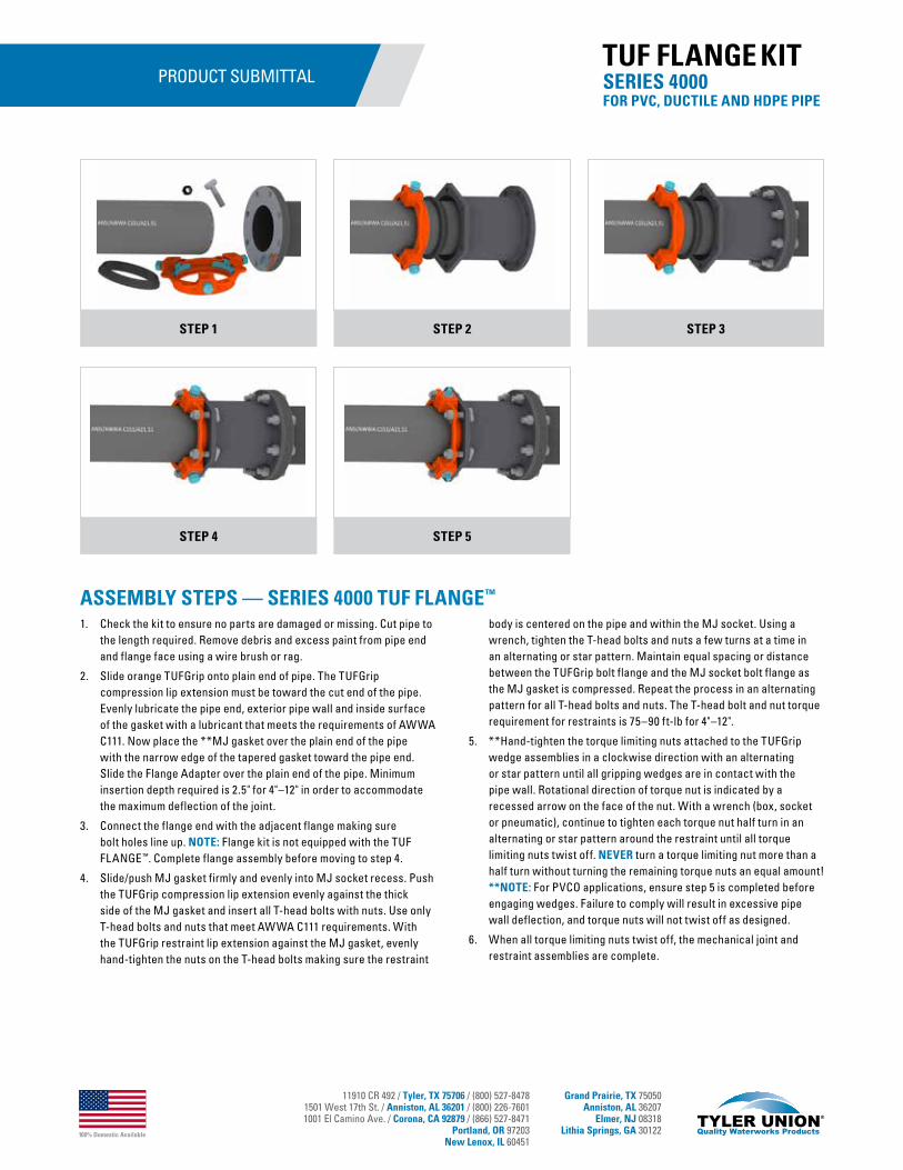
100% Domestic Available
11910 CR 492 / Tyler, TX 75706 / (800) 527-84781501 West 17th St. / Anniston, AL 36201 / (800) 226-76011001 El Camino Ave. / Corona, CA 92879 / (866) 527-8471
Portland, OR 97203New Lenox, IL 60451
Grand Prairie, TX 75050Anniston, AL 36207
Elmer, NJ 08318Lithia Springs, GA 30122
PRODUCT SUBMITTAL
ASSEMBLY STEPS — SERIES 4000 TUF FLANGE™
1. Check the kit to ensure no parts are damaged or missing. Cut pipe to the length required. Remove debris and excess paint from pipe end and flange face using a wire brush or rag.
2. Slide orange TUFGrip onto plain end of pipe. The TUFGrip compression lip extension must be toward the cut end of the pipe. Evenly lubricate the pipe end, exterior pipe wall and inside surface of the gasket with a lubricant that meets the requirements of AWWA C111. Now place the **MJ gasket over the plain end of the pipe with the narrow edge of the tapered gasket toward the pipe end. Slide the Flange Adapter over the plain end of the pipe. Minimum insertion depth required is 2.5" for 4"–12" in order to accommodate the maximum deflection of the joint.
3. Connect the flange end with the adjacent flange making sure bolt holes line up. NOTE: Flange kit is not equipped with the TUF FLANGE™. Complete flange assembly before moving to step 4.
4. Slide/push MJ gasket firmly and evenly into MJ socket recess. Push the TUFGrip compression lip extension evenly against the thick side of the MJ gasket and insert all T-head bolts with nuts. Use only T-head bolts and nuts that meet AWWA C111 requirements. With the TUFGrip restraint lip extension against the MJ gasket, evenly hand-tighten the nuts on the T-head bolts making sure the restraint
body is centered on the pipe and within the MJ socket. Using a wrench, tighten the T-head bolts and nuts a few turns at a time in an alternating or star pattern. Maintain equal spacing or distance between the TUFGrip bolt flange and the MJ socket bolt flange as the MJ gasket is compressed. Repeat the process in an alternating pattern for all T-head bolts and nuts. The T-head bolt and nut torque requirement for restraints is 75–90 ft-lb for 4"–12".
5. **Hand-tighten the torque limiting nuts attached to the TUFGrip wedge assemblies in a clockwise direction with an alternating or star pattern until all gripping wedges are in contact with the pipe wall. Rotational direction of torque nut is indicated by a recessed arrow on the face of the nut. With a wrench (box, socket or pneumatic), continue to tighten each torque nut half turn in an alternating or star pattern around the restraint until all torque limiting nuts twist off. NEVER turn a torque limiting nut more than a half turn without turning the remaining torque nuts an equal amount! **NOTE: For PVCO applications, ensure step 5 is completed before engaging wedges. Failure to comply will result in excessive pipe wall deflection, and torque nuts will not twist off as designed.
6. When all torque limiting nuts twist off, the mechanical joint and restraint assemblies are complete.
STEP 1 STEP 3STEP 2
STEP 4 STEP 5
SERIES 4000 FOR PVC, DUCTILE AND HDPE PIPE
TUF FLANGE KIT
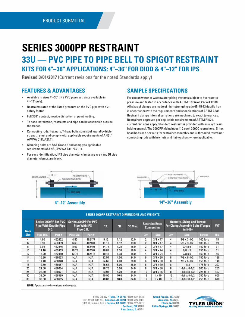
11910 CR 492 / Tyler, TX 75706 / (800) 527-84781501 West 17th St. / Anniston, AL 36201 / (800) 226-76011001 El Camino Ave. / Corona, CA 92879 / (866) 527-8471
Portland, OR 97203New Lenox, IL 60451
Grand Prairie, TX 75050Anniston, AL 36207
Elmer, NJ 08318Lithia Springs, GA 30122
SAMPLE SPECIFICATIONSFor use on water or wastewater piping systems subject to hydrostatic pressure and tested in accordance with ASTM D2774 or AWWA C600. All sizes of clamps are made of high-strength grade 65-45-12 ductile iron in accordance with the requirements and specifications of ASTM A536. Restraint clamps internal serrations are machined to exact tolerances. Restrainers approved per applicable requirements of ASTM F1674, current revisions apply. Standard restraint is provided with an alkyd resin baking enamel. The 3000PP kit includes 1) 2 each 3000C restrainers, 2) hex head bolts and hex nuts for restrainer assembly and 3) threaded restrainer connecting rods with hex nuts and flat washers where applicable.
4"–12" Assembly 14"–36" Assembly
FEATURES & ADVANTAGES• Available in sizes 4"–36" (IPS PVC pipe restraints available in
4"–12" only).
• Restraints rated at the listed pressure on the PVC pipe with a 2:1 safety factor.
• Full 360° contact, no pipe distortion or point loading.
• To ease installation, restraints and pipe can be assembled outside the trench.
• Connecting rods, hex nuts, T-head bolts consist of low-alloy high-strength steel and comply with applicable requirements of ANSI/AWWA C111/A21.11.
• Clamping bolts are SAE Grade 5 and comply to applicable requirements of ANSI/AWWA C111/A21.11.
• For easy identification, IPS pipe diameter clamps are grey and DI pipe diameter clamps are black.
SERIES 3000PP RESTRAINT
PRODUCT SUBMITTAL
33U — PVC PIPE TO PIPE BELL TO SPIGOT RESTRAINTKITS FOR 4"–36" APPLICATIONS: 4"–36" FOR DIOD & 4"–12" FOR IPSRevised 3/01/2017 (Current revisions for the noted Standards apply)
SERIES 3000PP RESTRAINT DIMENSIONS AND WEIGHTS
Nom Size
Series 3000PP For PVC Pipe With Ductile Pipe
O.D.
Series 3000PP For PVC Pipe With IPS
Pipe O.D.*A *B *C Max.
Restraint RodsConnecting
Quantity, Sizing and Torque For Clamp Assembly Bolts (Torque
in ft-lb)WT
Pipe Dia. Part # Pipe Dia. Part # Qty Size Qty Size Torque lbs.
4 4.80 462422 4.50 462477 9.12 1.12 12.0 2 3/4 x 17 4 5/8 x 3-1/2 100 ft-lb 156 6.90 462439 6.63 462484 11.12 1.12 13.0 2 3/4 x 17 4 5/8 x 3-1/2 100 ft-lb 198 9.05 462446 8.63 462491 14.74 1.25 15.0 2 3/4 x 17 4 3/4 x 5 150 ft-lb 31
10 11.10 462453 10.75 462507 16.81 1.38 16.0 4 3/4 x 24 4 7/8 x 5 150 ft-lb 5112 13.20 462460 12.75 462514 19.45 1.38 18.0 4 3/4 x 24 4 7/8 x 5 150 ft-lb 5514 15.30 488033 N/A N/A 22.54 4.00 24.0 6 3/4 x 30 8 7/8 x 6-1/2 150 ft-lb 13816 17.40 488040 N/A N/A 24.66 4.00 28.0 6 3/4 x 30 8 7/8 x 6-1/2 150 ft-lb 14818 19.50 488057 N/A N/A 26.64 5.06 28.0 8 3/4 x 30 8 1 x 8 175 ft-lb 20720 21.60 488064 N/A N/A 28.76 5.06 34.0 8 3/4 x 36 8 1-1/8 x 8-1/2 200 ft-lb 26524 25.80 488071 N/A N/A 33.98 5.20 34.0 12 3/4 x 36 8 1-1/8 x 8-1/2 225 ft-lb 40730 32.00 498599 N/A N/A 40.90 10.0 34.0 12 1 x 40 16 1-1/8 x 8-1/2 250 ft-lb 60536 38.30 498605 N/A N/A 48.00 10.0 34.0 12 1 x 40 16 1-1/8 x 8-1/2 250 ft-lb 670
NOTE: Approximate dimensions and weights.
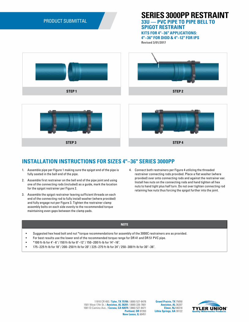
11910 CR 492 / Tyler, TX 75706 / (800) 527-84781501 West 17th St. / Anniston, AL 36201 / (800) 226-76011001 El Camino Ave. / Corona, CA 92879 / (866) 527-8471
Portland, OR 97203New Lenox, IL 60451
Grand Prairie, TX 75050Anniston, AL 36207
Elmer, NJ 08318Lithia Springs, GA 30122
PRODUCT SUBMITTAL
STEP 1 STEP 2
STEP 3 STEP 4
33U — PVC PIPE TO PIPE BELL TO SPIGOT RESTRAINT KITS FOR 4"–36" APPLICATIONS: 4"–36" FOR DIOD & 4"–12" FOR IPSRevised 3/01/2017
SERIES 3000PP RESTRAINT
NOTE
• Suggested hex head bolt and nut *torque recommendations for assembly of the 3000C restrainers are as provided.• For best results use the lower end of the recommended torque range for DR 41 and DR 51 PVC pipe.• *100 ft-lb for 4"–6" / 150 ft-lb for 8"–12" / 150–200 ft-lb for 14"–16".• 175–225 ft-lb for 18" / 200–250 ft-lb for 20" / 225–275 ft-lb for 24" / 250–300 ft-lb for 30"–36".
INSTALLATION INSTRUCTIONS FOR SIZES 4"–36" SERIES 3000PP1. Assemble pipe per Figure 1 making sure the spigot end of the pipe is
fully seated in the bell end of the pipe.
2. Assemble first restrainer on the bell end of the pipe joint and using one of the connecting rods (included) as a guide, mark the location for the spigot restrainer per Figure 2.
3. Assemble the spigot restrainer leaving sufficient threads on each end of the connecting rod to fully install washer (where provided) and fully engage nut per Figure 3. Tighten the restrainer clamp assembly bolts on each side evenly to the recommended torque maintaining even gaps between the clamp pads.
4. Connect both restrainers per Figure 4 utilizing the threaded restrainer connecting rods provided. Place a flat washer (where provided) over onto connecting rods and against the restrainer ear. Install hex nuts on the connecting rods and hand tighten all hex nuts to hand tight plus half turn. Do not over tighten connecting rod retaining hex nuts thus forcing the spigot further into the joint.
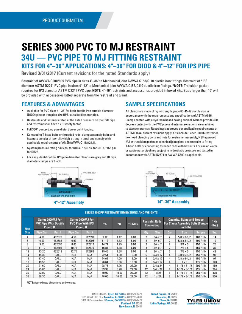
11910 CR 492 / Tyler, TX 75706 / (800) 527-84781501 West 17th St. / Anniston, AL 36201 / (800) 226-76011001 El Camino Ave. / Corona, CA 92879 / (866) 527-8471
Portland, OR 97203New Lenox, IL 60451
Grand Prairie, TX 75050Anniston, AL 36207
Elmer, NJ 08318Lithia Springs, GA 30122
FEATURES & ADVANTAGES• Available for PVC sizes 4"–36" for both ductile iron outside diameter
(DIOD) pipe or iron pipe size (IPS) outside diameter pipe.
• Restraints and fasteners rated at the listed pressure on the PVC pipe and restraint shall have a 2:1 safety factor.
• Full 360° contact, no pipe distortion or point loading.
• Connecting T-head bolts or threaded rods, clamp assembly bolts and hex nuts consist of low-alloy high-strength steel and comply with applicable requirements of ANSI/AWWA C111/A21.11.
• System pressure rating *305 psi for DR14i, *235 psi for DR18, *165 psi for DR25.
• For easy identification, IPS pipe diameter clamps are grey and DI pipe diameter clamps are black.
PRODUCT SUBMITTAL
34U — PVC PIPE TO MJ FITTING RESTRAINTKITS FOR 4"–36" APPLICATIONS: 4"–36" FOR DIOD & 4"–12" FOR IPS PIPERevised 3/01/2017 (Current revisions for the noted Standards apply)
SERIES 3000 PVC TO MJ RESTRAINT
Restraint of AWWA C900/905 PVC pipe in sizes 4"–36" to Mechanical joint AWWA C153/C110 ductile iron fittings. Restraint of *IPS diameter ASTM D2241 PVC pipe in sizes 4"–12" to Mechanical joint AWWA C153/C110 ductile iron fittings. *NOTE: Transition gasket required for IPS diameter ASTM D2241 PVC pipe. NOTE: 4"–16" restraints and accessories provided in boxed kits. Sizes larger than 16" will be provided with accessories kitted separate from the restraint and gland.
SAMPLE SPECIFICATIONSAll clamps are made of high-strength grade 65-45-12 ductile iron in accordance with the requirements and specifications of ASTM A536. Clamps coated with alkyd resin based baking enamel. Clamps provide 360 degree contact with the PVC pipe and internal serrations are machined to exact tolerances. Restrainers approved per applicable requirements of ASTM F1674, current revisions apply. Kits include 1 each 3000C restrainer, hex head clamping bolts and nuts for restrainer assembly, NSF approved MJ or transition gasket, mechanical joint gland and restraint to fitting T-head bolts or connecting threaded rods with hex nuts. For use on water or wastewater pipelines subject to hydrostatic pressure and tested in accordance with ASTM D2774 or AWWA C600 as applicable.
4"–12" Assembly 14"–36" Assembly
SERIES 3000PP RESTRAINT DIMENSIONS AND WEIGHTS
Nom Size
Series 3000MJ For PVC Pipe With Ductile
Pipe O.D.
Series 3000MJ For PVC Pipe With IPS
Pipe O.D.*A *B *C Max.
Restraint RodsConnecting
Quantity, Sizing and Torque For Clamp Assembly Bolts (Torque
in ft-lb)
*Kit(lbs.)
Pipe Dia. Part # Pipe Dia. Part # Qty Size Qty Size Torque lbs.
4 4.80 462576 4.50 512899 9.12 1.12 6.00 2 3/4 x 7 2 5/8 x 3-1/2 100 ft-lb 146 6.90 462583 6.63 512905 11.12 1.12 6.00 2 3/4 x 7 2 5/8 x 3-1/2 100 ft-lb 198 9.05 462590 8.63 512912 14.74 1.25 6.00 2 3/4 x 7 2 3/4 x 5 150 ft-lb 26
10 11.10 462606 10.75 512875 16.81 1.38 6.00 4 3/4 x 7 2 7/8 x 5 150 ft-lb 3912 13.20 462613 12.75 512882 19.45 1.38 6.00 4 3/4 x 7 2 7/8 x 5 150 ft-lb 4214 15.30 CALL N/A N/A 22.54 4.00 15.00 6 3/4 x 17 4 7/8 x 6-1/2 150 ft-lb 9216 17.40 CALL N/A N/A 24.66 4.00 15.00 6 3/4 x 17 4 7/8 x 6-1/2 150 ft-lb 9718 19.50 CALL N/A N/A 26.64 5.06 15.00 8 3/4 x 17 4 1 x 8 175 ft-lb 14320 21.60 CALL N/A N/A 28.76 5.06 22.00 8 3/4 x 24 4 1-1/8 x 8-1/2 200 ft-lb 16924 25.80 CALL N/A N/A 33.98 5.20 22.00 12 3/4 x 24 4 1-1/8 x 8-1/2 225 ft-lb 22430 32.00 CALL N/A N/A 40.90 10.00 22.00 12 1 x 24 8 1-1/8 x 8-1/2 250 ft-lb 40836 38.30 CALL N/A N/A 48.00 10.00 22.00 12 1 x 24 8 1-1/8 x 8-1/2 250 ft-lb 500
NOTE: Approximate dimensions and weights.

11910 CR 492 / Tyler, TX 75706 / (800) 527-84781501 West 17th St. / Anniston, AL 36201 / (800) 226-76011001 El Camino Ave. / Corona, CA 92879 / (866) 527-8471
Portland, OR 97203New Lenox, IL 60451
Grand Prairie, TX 75050Anniston, AL 36207
Elmer, NJ 08318Lithia Springs, GA 30122
PRODUCT SUBMITTAL
FIGURE 1
FIGURE 1
FIGURE 2
FIGURE 2
FIGURE 3
FIGURE 3
FIGURE 4
FIGURE 4
FIGURE 5
INSTALLATION INSTRUCTIONS FOR SIZES 4"–12" SERIES 3000MJ1. Assemble the mechanical joint, installing gasket, gland and
T-head bolts per AWWA C600 standard, leave out the T-head bolt corresponding to the restrainer ears per Figure 1.
2. Per Figure 2, use a 7" T-head bolt (included) as a guide and mark the location on the pipe where the restrainer will be assembled.
3. Assemble restrainer per Figure 3, leaving sufficient threads on the end of the T-head bolt to fully engage nut.
4. Tighten the restrainer clamp assembly bolts on each side evenly to the recommended torque maintaining even gaps between the clamp pads. (100 ft-lb for 4"–6" and 150 ft-lb for 8"–12").
5. Connect restrainer to fitting per Figure 5. Insert the 7" T-head bolt (bolt and 2 hex nuts provided) through the bolt flange installing a hex nut between the gland and restrainer. Tighten the hex nut up to the gland per AWWA C600 standard. Tighten the second hex nut up to the restrainer as show in Figure 5. Use additional hex nuts (not included) on the inside of the restrainer ear if joint is expected to contract.
INSTALLATION INSTRUCTIONS FOR SIZES 14"–36" SERIES 3000MJ1. Assemble the mechanical joint, installing gasket, gland and
T-head bolts per AWWA C600 standard, leave out the T-head bolt corresponding to the restrainer ears per Figure 1.
2. Per Figure 2, use a connecting rod (included) as a guide and mark the location on the pipe where the restrainer will be assembled.
3. Assemble restrainer per Figure 3, leaving sufficient threads on the end of the connecting rod to fully install washer and fully engage hex nut. Tighten the restrainer clamp assembly bolts on each side evenly to the recommended torque maintaining even gaps between the clamp pads (150–200 ft-lb for 14"–16", 175–225 ft-lb for 18", 200–250 ft-lb for 20", 225–275 ft-lb for 24", 250–300 ft-lb for 30" and 250–300 ft-lb for 36").
4. Connect restrainer to fitting per Figure 4. Inserting the rods through the restrainer ears (rod and 3 hex nuts provided for each ear), gland and fitting bolt hole. Install one hex nut behind fitting bell, one hex nut against the gland and one hex nut behind the restrainer ear against the washer. Tighten hex nut up to gland per AWWA C600 standard. Use additional hex nuts (not included) on the inside of the restrainer ear if joint is expected to contract.
34U — PVC TO MJ RESTRAINT KITS FOR 4"–36" APPLICATIONS: 4"–36" FOR DIOD & 4"–12" FOR IPS PIPERevised 3/01/2017
SERIES 3000 RESTRAINT
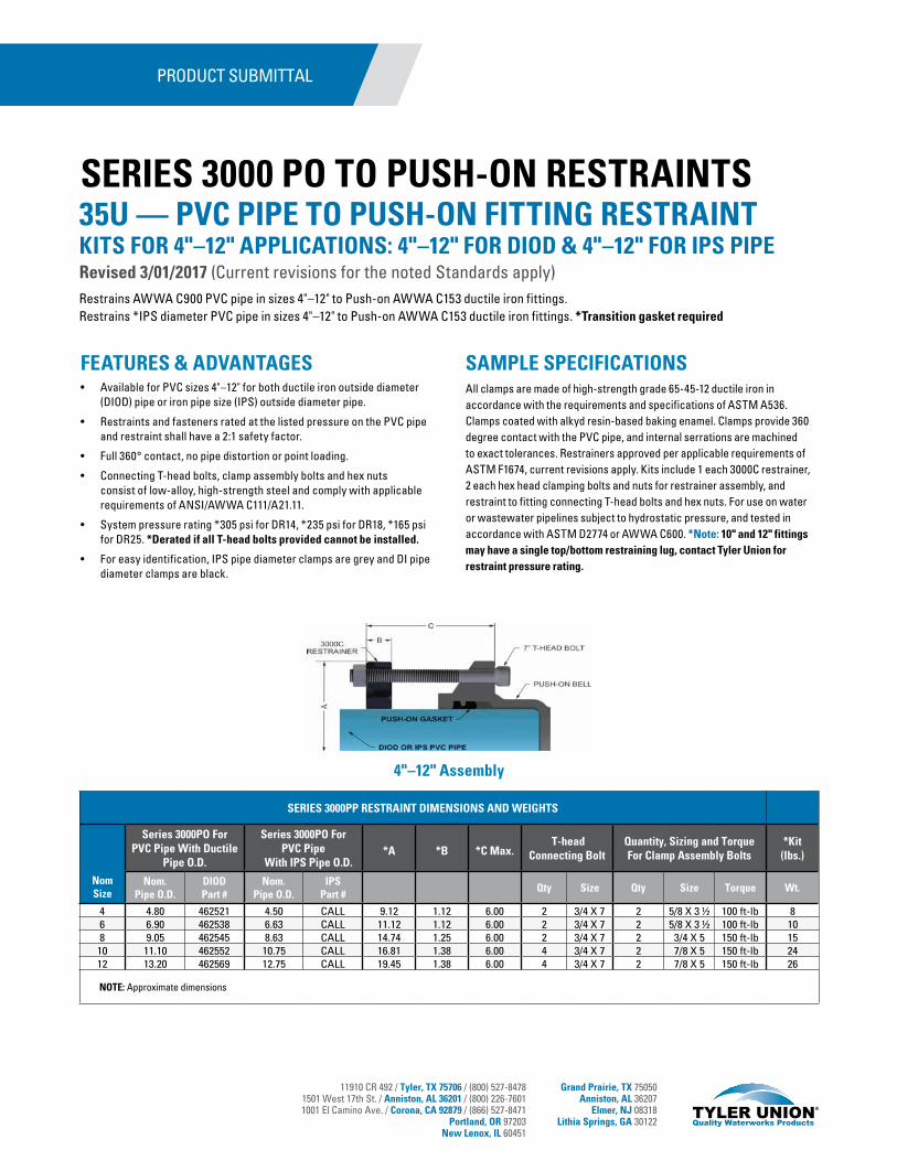
11910 CR 492 / Tyler, TX 75706 / (800) 527-84781501 West 17th St. / Anniston, AL 36201 / (800) 226-76011001 El Camino Ave. / Corona, CA 92879 / (866) 527-8471
Portland, OR 97203New Lenox, IL 60451
Grand Prairie, TX 75050Anniston, AL 36207
Elmer, NJ 08318Lithia Springs, GA 30122
FEATURES & ADVANTAGES• Available for PVC sizes 4"–12" for both ductile iron outside diameter
(DIOD) pipe or iron pipe size (IPS) outside diameter pipe.
• Restraints and fasteners rated at the listed pressure on the PVC pipe and restraint shall have a 2:1 safety factor.
• Full 360° contact, no pipe distortion or point loading.
• Connecting T-head bolts, clamp assembly bolts and hex nuts consist of low-alloy, high-strength steel and comply with applicable requirements of ANSI/AWWA C111/A21.11.
• System pressure rating *305 psi for DR14, *235 psi for DR18, *165 psi for DR25. *Derated if all T-head bolts provided cannot be installed.
• For easy identification, IPS pipe diameter clamps are grey and DI pipe diameter clamps are black.
PRODUCT SUBMITTAL
35U — PVC PIPE TO PUSH-ON FITTING RESTRAINTKITS FOR 4"–12" APPLICATIONS: 4"–12" FOR DIOD & 4"–12" FOR IPS PIPERevised 3/01/2017 (Current revisions for the noted Standards apply)
SERIES 3000 PO TO PUSH-ON RESTRAINTS
Restrains AWWA C900 PVC pipe in sizes 4"–12" to Push-on AWWA C153 ductile iron fittings.Restrains *IPS diameter PVC pipe in sizes 4"–12" to Push-on AWWA C153 ductile iron fittings. *Transition gasket required
SAMPLE SPECIFICATIONSAll clamps are made of high-strength grade 65-45-12 ductile iron in accordance with the requirements and specifications of ASTM A536. Clamps coated with alkyd resin-based baking enamel. Clamps provide 360 degree contact with the PVC pipe, and internal serrations are machined to exact tolerances. Restrainers approved per applicable requirements of ASTM F1674, current revisions apply. Kits include 1 each 3000C restrainer, 2 each hex head clamping bolts and nuts for restrainer assembly, and restraint to fitting connecting T-head bolts and hex nuts. For use on water or wastewater pipelines subject to hydrostatic pressure, and tested in accordance with ASTM D2774 or AWWA C600. *Note: 10" and 12" fittings may have a single top/bottom restraining lug, contact Tyler Union for restraint pressure rating.
4"–12" Assembly
SERIES 3000PP RESTRAINT DIMENSIONS AND WEIGHTS
Nom Size
Series 3000PO For PVC Pipe With Ductile
Pipe O.D.
Series 3000PO For PVC Pipe
With IPS Pipe O.D.*A *B *C Max.
T-head Connecting Bolt
Quantity, Sizing and Torque For Clamp Assembly Bolts
*Kit(lbs.)
Nom. Pipe O.D.
DIOD Part #
Nom. Pipe O.D.
IPS Part #
Qty Size Qty Size Torque Wt.
4 4.80 462521 4.50 CALL 9.12 1.12 6.00 2 3/4 X 7 2 5/8 X 3 ½ 100 ft-lb 86 6.90 462538 6.63 CALL 11.12 1.12 6.00 2 3/4 X 7 2 5/8 X 3 ½ 100 ft-lb 108 9.05 462545 8.63 CALL 14.74 1.25 6.00 2 3/4 X 7 2 3/4 X 5 150 ft-lb 15
10 11.10 462552 10.75 CALL 16.81 1.38 6.00 4 3/4 X 7 2 7/8 X 5 150 ft-lb 2412 13.20 462569 12.75 CALL 19.45 1.38 6.00 4 3/4 X 7 2 7/8 X 5 150 ft-lb 26
NOTE: Approximate dimensions

11910 CR 492 / Tyler, TX 75706 / (800) 527-84781501 West 17th St. / Anniston, AL 36201 / (800) 226-76011001 El Camino Ave. / Corona, CA 92879 / (866) 527-8471
Portland, OR 97203New Lenox, IL 60451
Grand Prairie, TX 75050Anniston, AL 36207
Elmer, NJ 08318Lithia Springs, GA 30122
PRODUCT SUBMITTAL
FIGURE 1 FIGURE 2 FIGURE 3
FIGURE 4 FIGURE 5
INSTALLATION INSTRUCTIONS FOR SIZES 4"–12" SERIES 3000PO:1. Figure 1, Push-On joint assembly per AWWA C600 — make sure the
pipe spigot is beveled, ensure the fitting gasket seat is clean and dry prior to joint assembly. Insert the gasket into the fitting gasket seat and evenly lubricate the inside surface of the gasket only. Confirm the exterior pipe wall of the spigot end of the pipe is clean and free from raised or rough areas. Keeping the pipe straight with the fitting socket, insert the spigot end of the pipe fully against the pipe stop inside the fitting socket.
2. Per Figure 2, use a 7" T-head bolt (included) as a guide and mark the location on the pipe where the restrainer will be assembled.
3. Assemble restrainer per Figure 3, leaving sufficient threads on the end of the T-head bolt to fully engage nut.
4. Tighten the restrainer clamp assembly bolts on each side evenly to the recommended torque maintaining even gaps between the clamp pads (100 ft-lb for 4"-6" and 150 ft-lb for 8"-12").
5. Connect restrainer to fitting per Figure 5. Insert the 7" T-head bolt (bolts and hex nuts provided) through the fitting ear and tighten the hex nut up to the restrainer hand tight plus a half turn. Do not over tighten T-head bolts thus forcing the spigot further into the joint.
35U — PVC TO PUSH-ON RESTRAINT KITS FOR 4"–12" APPLICATIONS: 4"–12" FOR DIOD & 4"–12" FOR IPS PIPERevised 3/01/2017
SERIES 3000 PO RESTRAINT
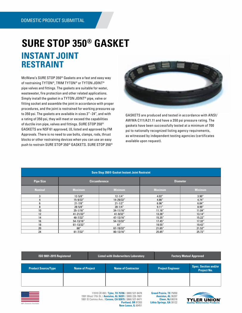
100% Domestic Available
11910 CR 492 / Tyler, TX 75706 / (800) 527-84781501 West 17th St. / Anniston, AL 36201 / (800) 226-76011001 El Camino Ave. / Corona, CA 92879 / (866) 527-8471
Portland, OR 97203New Lenox, IL 60451
Grand Prairie, TX 75050Anniston, AL 36207
Elmer, NJ 08318Lithia Springs, GA 30122
McWane’s SURE STOP 350® Gaskets are a fast and easy way of restraining TYTON®, TRIM TYTON® or TYTON JOINT® pipe valves and fittings. The gaskets are suitable for water, wastewater, fire protection and other related applications. Simply install the gasket in a TYTON JOINT® pipe, valve or fitting socket and assemble the joint in accordance with proper procedures, and the joint is restrained for working pressures up to 350 psi. The gaskets are available in sizes 3”–24”, and with a rating of 350 psi, they will meet or exceed the capabilities of ductile iron pipe, valves and fittings. SURE STOP 350® GASKETS are NSF 61 approved, UL listed and approved by FM Approvals. There is no need to use bolts, clamps, rods, thrust blocks or other restraining devices when you can use an easy push to restrain SURE STOP 350® GASKETS. SURE STOP 350®
GASKETS are produced and tested in accordance with ANSI/AWWA C111/A21.11 and have a 350 psi pressure rating. The gaskets have been successfully tested at a minimum of 700 psi to nationally recognized listing agency requirements, as witnessed by independent testing agencies (certificates available upon request).
INSTANT JOINT RESTRAINT
SURE STOP 350® GASKET
DOMESTIC PRODUCT SUBMITTAL
Product Source/Type Name of Project Name of Contractor Project EngineerSpec. Section and/or
Project No.
ISO 9001-2015 Registered Listed with Underwriters Laboratory Factory Mutual Approved
Sure Stop 350® Gasket Instant Joint Restraint
Pipe Size Circumference Diameter
Nominal Maximum Minimum Maximum Minimum
3 12-5/8” 12-1/4” 4.02” 3.90”4 15-9/32” 14-29/32” 4.86” 4.74”6 21-7/8” 21-1/2” 6.96” 6.84”8 28-5/8” 28-1/4” 9.11” 8.99”
10 35-1/16” 34-11/16” 11.16” 11.04”12 41-21/32” 41-9/32” 13.26” 13.14”14 48-7/32” 47-13/16” 15.35” 15.22”16 54-13/16” 54-13/32” 17.45” 17.32”18 61-13/32” 61” 19.55” 19.42”20 68” 67-19/32” 21.65” 21.52”24 81-7/32” 80-13/16” 25.85” 25.72”
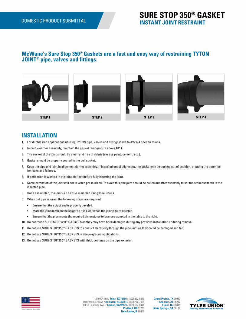
100% Domestic Available
11910 CR 492 / Tyler, TX 75706 / (800) 527-84781501 West 17th St. / Anniston, AL 36201 / (800) 226-76011001 El Camino Ave. / Corona, CA 92879 / (866) 527-8471
Portland, OR 97203New Lenox, IL 60451
Grand Prairie, TX 75050Anniston, AL 36207
Elmer, NJ 08318Lithia Springs, GA 30122
DOMESTIC PRODUCT SUBMITTAL
INSTALLATION1. For ductile iron applications utilizing TYTON pipe, valves and fittings made to AWWA specifications.
2. In cold weather assembly, maintain the gasket temperature above 40° F.
3. The socket of the joint should be clean and free of debris (excess paint, cement, etc.).
4. Gasket should be properly seated in the bell socket.
5. Keep the pipe and joint in alignment during assembly. If installed out of alignment, the gasket can be pushed out of position, creating the potential for leaks and failures.
6. If deflection is wanted in the joint, deflect before fully inserting the joint.
7. Some extension of the joint will occur when pressurized. To avoid this, the joint should be pulled out after assembly to set the stainless teeth in the inserted pipe.
8. Once assembled, the joint can be disassembled using steel shims.
9. When cut pipe is used, the following steps are required:
• Ensure that the spigot end is properly beveled.
• Mark the joint depth on the spigot so it is clear when the joint is fully inserted.
• Ensure that the pipe meets the required dimensional tolerances as noted in the table to the right.
10. Do not reuse SURE STOP 350® GASKETS as they may have been damaged during any previous installation or during removal.
11. Do not use SURE STOP 350® GASKETS to conduct electricity through the pipe joint as they could be damaged and fail.
12. Do not use SURE STOP 350® GASKETS in above-ground applications.
13. Do not use SURE STOP 350® GASKETS with thick coatings on the pipe exterior.
STEP 1 STEP 2 STEP 3 STEP 4
INSTANT JOINT RESTRAINT SURE STOP 350® GASKET
McWane’s Sure Stop 350® Gaskets are a fast and easy way of restraining TYTON JOINT® pipe, valves and fittings.
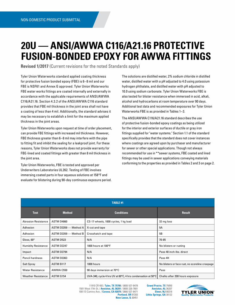
11910 CR 492 / Tyler, TX 75706 / (800) 527-84781501 West 17th St. / Anniston, AL 36201 / (800) 226-76011001 El Camino Ave. / Corona, CA 92879 / (866) 527-8471
Portland, OR 97203New Lenox, IL 60451
Grand Prairie, TX 75050Anniston, AL 36207
Elmer, NJ 08318Lithia Springs, GA 30122
NON-DOMESTIC PRODUCT SUBMITTAL
Tyler Union Waterworks standard applied coating thickness for protective fusion bonded epoxy (FBE) is 6–8 mil and our FBE is NSF61 and Annex G approved. Tyler Union Waterworks FBE water works fittings are coated internally and externally in accordance with the applicable requirements of ANSI/AWWA C116/A21.16. Section 4.3.2 of the ANSI/AWWA C116 standard provides that FBE mil thickness in the joint area shall not have a coating of less than 4 mil. Additionally, the standard advises it may be necessary to establish a limit for the maximum applied thickness in the joint areas.
Tyler Union Waterworks upon request at time of order placement, can provide FBE fittings with increased mil thickness. However, FBE thickness greater than 6–8 mil may interfere with the pipe to fitting fit and inhibit the sealing for a leakproof joint. For these reasons, Tyler Union Waterworks does not provide warranty for FBE-lined and coated fittings with greater than 8 mil thickness in the joint area.
Tyler Union Waterworks, FBE is tested and approved per Underwriters Laboratories UL262. Testing of FBE involves immersing coated parts in four aqueous solutions at 158°F and evaluate for blistering during 90-day continuous exposure period.
The solutions are distilled water, 2% sodium chloride in distilled water, distilled water with a pH adjusted to 4.0 using potassium hydrogen phthalate, and distilled water with pH adjusted to 10.0 using sodium carbonate. Tyler Union Waterworks FBE is also tested for blister resistance when immersed in acid, alkali, alcohol and hydrocarbons at room temperature over 90 days. Additional test data and recommended exposures for Tyler Union Waterworks FBE is as provided in Tables 1–3.
The ANSI/AWWA C116/A21.16 standard describes the use of protective fusion-bonded epoxy coatings as being utilized for the interior and exterior surfaces of ductile or gray iron fittings supplied for "water systems." Section 1.1 of the standard specifically provides that the standard does not cover instances where coatings are agreed upon by purchaser and manufacturer for sewer or other special applications. Though not always recommended for use in **sewer systems, FBE coated and lined fittings may be used in sewer applications conveying materials conforming to the properties as provided in Tables 2 and 3 on page 2.
TABLE #1
Test Method Conditions Result
Abrasion Resistance ASTM D4060 CS-17 wheels, 1000 cycles, 1 kg load 32 mg loss
Adhesion ASTM D3359 — Method A X-cut and tape 5A
Adhesion ASTM D3359 — Method B Crosshatch and tape 5B
Gloss, 60° ASTM D523 N/A 70-85
Humidity Resistance ASTM D2247 1000 hours at 100°F No blisters or rusting
Impact ASTM D2794 N/A Pass 40 inch-lbs. direct
Pencil hardness ASTM D3363 N/A Pass 4H
Salt Spray ASTM B117 1000 hours No blisters or face rust, no scoreline creepage
Water Resistance AWWA C550 90 days immersion at 70°C Pass
Weather Resistance ASTM G154 UVA-340, cycle 4 hrs UV at 60°C, 4 hrs condensation at 50°C Chalks after 200 hours exposure
Revised 1/2017 (Current revisions for the noted Standards apply)
20U — ANSI/AWWA C116/A21.16 PROTECTIVE FUSION-BONDED EPOXY FOR AWWA FITTINGS
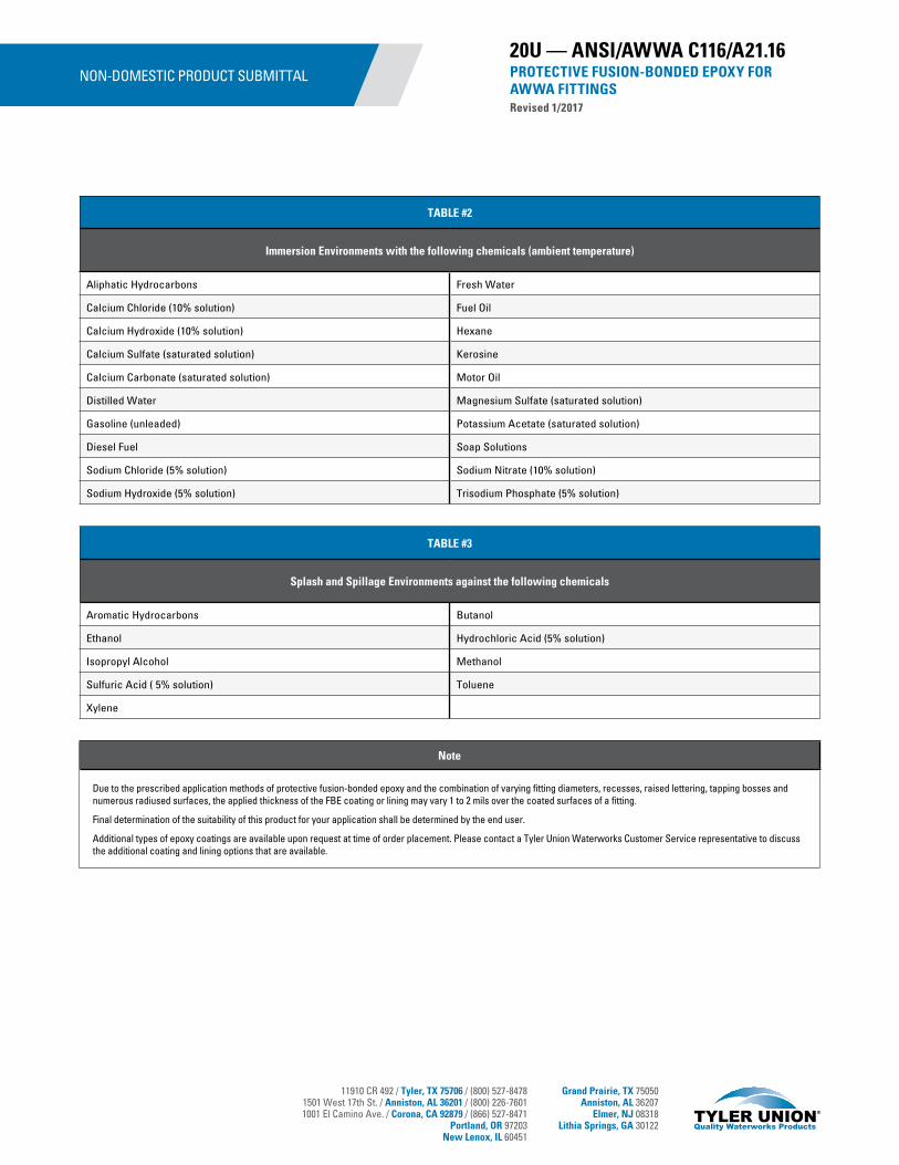
11910 CR 492 / Tyler, TX 75706 / (800) 527-84781501 West 17th St. / Anniston, AL 36201 / (800) 226-76011001 El Camino Ave. / Corona, CA 92879 / (866) 527-8471
Portland, OR 97203New Lenox, IL 60451
Grand Prairie, TX 75050Anniston, AL 36207
Elmer, NJ 08318Lithia Springs, GA 30122
Note
Due to the prescribed application methods of protective fusion-bonded epoxy and the combination of varying fitting diameters, recesses, raised lettering, tapping bosses and numerous radiused surfaces, the applied thickness of the FBE coating or lining may vary 1 to 2 mils over the coated surfaces of a fitting.
Final determination of the suitability of this product for your application shall be determined by the end user.
Additional types of epoxy coatings are available upon request at time of order placement. Please contact a Tyler Union Waterworks Customer Service representative to discuss the additional coating and lining options that are available.
20U — ANSI/AWWA C116/A21.16PROTECTIVE FUSION-BONDED EPOXY FOR AWWA FITTINGSRevised 1/2017
TABLE #2
Immersion Environments with the following chemicals (ambient temperature)
Aliphatic Hydrocarbons Fresh Water
Calcium Chloride (10% solution) Fuel Oil
Calcium Hydroxide (10% solution) Hexane
Calcium Sulfate (saturated solution) Kerosine
Calcium Carbonate (saturated solution) Motor Oil
Distilled Water Magnesium Sulfate (saturated solution)
Gasoline (unleaded) Potassium Acetate (saturated solution)
Diesel Fuel Soap Solutions
Sodium Chloride (5% solution) Sodium Nitrate (10% solution)
Sodium Hydroxide (5% solution) Trisodium Phosphate (5% solution)
TABLE #3
Splash and Spillage Environments against the following chemicals
Aromatic Hydrocarbons Butanol
Ethanol Hydrochloric Acid (5% solution)
Isopropyl Alcohol Methanol
Sulfuric Acid ( 5% solution) Toluene
Xylene
NON-DOMESTIC PRODUCT SUBMITTAL
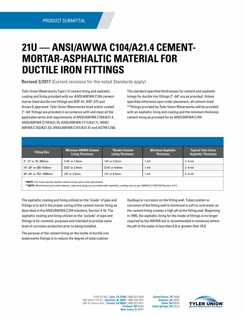
11910 CR 492 / Tyler, TX 75706 / (800) 527-84781501 West 17th St. / Anniston, AL 36201 / (800) 226-76011001 El Camino Ave. / Corona, CA 92879 / (866) 527-8471
Portland, OR 97203New Lenox, IL 60451
Grand Prairie, TX 75050Anniston, AL 36207
Elmer, NJ 08318Lithia Springs, GA 30122
Tyler Union Waterworks Type I-II cement lining and asphaltic coating and lining provided with our ANSI/AWWA C104 cement-mortar lined ductile iron fittings are NSF-61, NSF-372 and Annex G approved. Tyler Union Waterworks lined and/or coated 2"–64" fittings are provided in accordance with and meet all the applicable terms and requirements of ANSI/AWWA C104/A21.4, ANSI/AWWA C110/A21.10, ANSI/AWWA C111/A21.11, ANSI/AWWA C153/A21.53, ANSI/AWWA C151/A21.51 and ASTM C150.
The standard specified thicknesses for cement and asphaltic linings for ductile iron fittings 2"–64" are as provided. Unless specified otherwise upon order placement, all cement-lined **fittings provided by Tyler Union Waterworks will be provided with an asphaltic lining and coating and the minimum thickness cement lining as provided for by ANSI/AWWA C104.
The asphaltic coating and lining utilized on the "inside" of pipe and fittings is to aid in the proper curing of the cement mortar lining as described in the ANSI/AWWA C104 standard, Section 4.10. The asphaltic coating and lining utilized on the "outside" of pipe and fittings is for cosmetic purposes and intended to provide some level of corrosion protection prior to being installed.
The purpose of the cement lining on the inside of ductile iron waterworks fittings is to reduce the degree of tuberculation
(buildup) or corrosion on the fitting wall. Tuberculation or corrosion of the fitting wall is minimized in soft or acid water as the cement lining creates a high pH at the fitting wall. Beginning in 1995, the asphaltic lining for the inside of fittings is no longer required by the AWWA but is recommended in instances where the pH of the water is less than 6.0 or greater than 10.0.
PRODUCT SUBMITTAL
Fitting SizeMinimum AWWA Cement
Lining Thickness*Double CementLining Thickness
Minimum Asphaltic Thickness
Typical Tyler Union Asphaltic Thickness
2"–12" or 76–305mm 1/16" or 1.6mm 1/8" or 3.2mm 1 mil 2–4 mil
14"–24" or 356–610mm 3/32" or 2.4mm 3/16" or 4.8mm 1 mil 2–4 mil
30"–64" or 762–1600mm 1/8" or 3.2mm 1/4" or 6.4mm 1 mil 2–4 mil
*NOTE: You must specify double cement lining upon order placement.**NOTE: Mechanical joint solid sleeves, caps and plugs are provided with asphaltic coating only as per AWWA C110/C153 Section 4.4.3.
Revised 3/2017 (Current revisions for the noted Standards apply)
21U — ANSI/AWWA C104/A21.4 CEMENT-MORTAR-ASPHALTIC MATERIAL FOR DUCTILE IRON FITTINGS
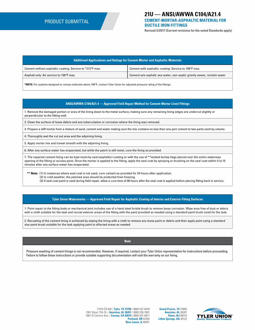
11910 CR 492 / Tyler, TX 75706 / (800) 527-84781501 West 17th St. / Anniston, AL 36201 / (800) 226-76011001 El Camino Ave. / Corona, CA 92879 / (866) 527-8471
Portland, OR 97203New Lenox, IL 60451
Grand Prairie, TX 75050Anniston, AL 36207
Elmer, NJ 08318Lithia Springs, GA 30122
PRODUCT SUBMITTAL
Note
Pressure washing of cement linings is not recommended. However, if required, contact your Tyler Union representative for instructions before proceeding. Failure to follow these instructions or provide suitable supporting documentation will void the warranty on our lining.
21U — ANSI/AWWA C104/A21.4CEMENT-MORTAR-ASPHALTIC MATERIAL FOR DUCTILE IRON FITTINGSRevised 3/2017 (Current revisions for the noted Standards apply)
Additional Applications and Ratings for Cement-Mortar and Asphaltic Materials
Cement without asphaltic coating: Service to *212°F max. Cement with asphaltic coating: Service to 150°F max.
Asphalt only: Air service to 150°F max. Cement w/o asphalt: sea water, non-septic gravity sewer, reclaim water
*NOTE: For systems designed to convey materials above 150°F, contact Tyler Union for adjusted pressure rating of the fittings.
ANSI/AWWA C104/A21.4 — Approved Field Repair Method for Cement-Mortar Lined Fittings
1. Remove the damaged portion or area of the lining down to the metal surface, making sure any remaining lining edges are undercut slightly or perpendicular to the fitting wall.
2. Clean the surface of loose debris and any tuberculation or corrosion where the lining was removed.
3. Prepare a stiff mortar from a mixture of sand, cement and water making sure the mix contains no less than one part cement to two parts sand by volume.
4. Thoroughly wet the cut out area and the adjoining lining.
5. Apply mortar mix and trowel smooth with the adjoining lining.
6. After any surface water has evaporated, but while the patch is still moist, cure the lining as provided.
7. The repaired cement lining can be kept moist by seal (asphaltic) coating or with the use of **wetted burlap bags placed over the entire waterway opening of the fitting or access point. Once the mortar is applied to the fitting, apply the seal coat by spraying or brushing on the seal coat within 5 to 15 minutes after any surface water has evaporated.
** Note: (1) In instances where seal coat is not used, cure cement as provided for 24 hours after application. (2) In cold weather, the patched area should be protected from freezing. (3) If seal coat paint is used during field repair, allow a cure time of 48 hours after the seal coat is applied before placing fitting back in service.
Tyler Union Waterworks — Approved Field Repair for Asphaltic Coating of Interior and Exterior Fitting Surfaces
1. Paint repair to the fitting body or mechanical joint includes use of a hand steel bristle brush to remove loose corrosion. Wipe area free of dust or debris with a cloth suitable for the task and recoat exterior areas of the fitting with the paint provided as needed using a standard paint brush sized for the task.
2. Recoating of the cement lining is achieved by wiping the lining with a cloth to remove any loose paint or debris and then apply paint using a standard size paint brush suitable for the task applying paint to affected areas as needed.
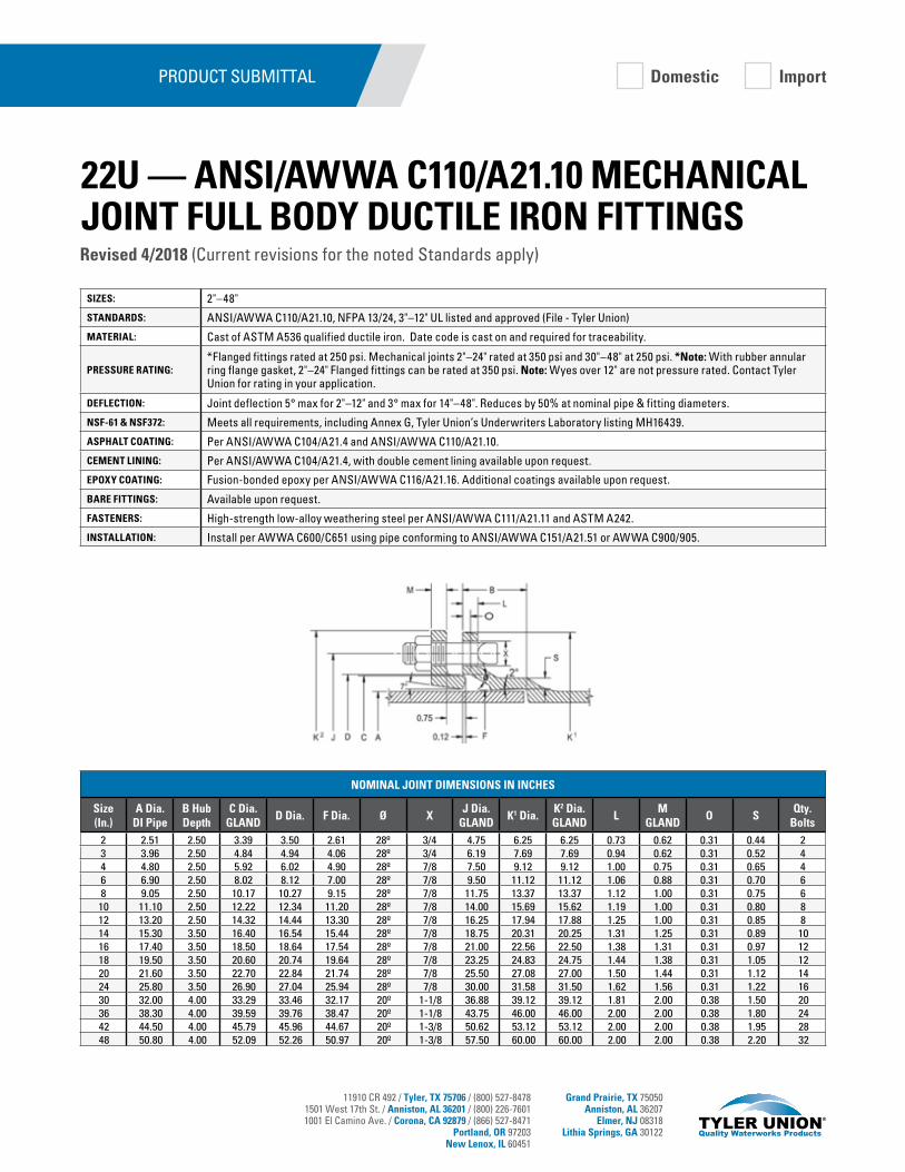
11910 CR 492 / Tyler, TX 75706 / (800) 527-84781501 West 17th St. / Anniston, AL 36201 / (800) 226-76011001 El Camino Ave. / Corona, CA 92879 / (866) 527-8471
Portland, OR 97203New Lenox, IL 60451
Grand Prairie, TX 75050Anniston, AL 36207
Elmer, NJ 08318Lithia Springs, GA 30122
SIZES: 2"–48"
STANDARDS: ANSI/AWWA C110/A21.10, NFPA 13/24, 3"–12" UL listed and approved (File - Tyler Union)
MATERIAL: Cast of ASTM A536 qualified ductile iron. Date code is cast on and required for traceability.
PRESSURE RATING:*Flanged fittings rated at 250 psi. Mechanical joints 2"–24" rated at 350 psi and 30"–48" at 250 psi. *Note: With rubber annular ring flange gasket, 2"–24" Flanged fittings can be rated at 350 psi. Note: Wyes over 12" are not pressure rated. Contact Tyler Union for rating in your application.
DEFLECTION: Joint deflection 5° max for 2"–12" and 3° max for 14"–48". Reduces by 50% at nominal pipe & fitting diameters.
NSF-61 & NSF372: Meets all requirements, including Annex G, Tyler Union’s Underwriters Laboratory listing MH16439.
ASPHALT COATING: Per ANSI/AWWA C104/A21.4 and ANSI/AWWA C110/A21.10.
CEMENT LINING: Per ANSI/AWWA C104/A21.4, with double cement lining available upon request.
EPOXY COATING: Fusion-bonded epoxy per ANSI/AWWA C116/A21.16. Additional coatings available upon request.
BARE FITTINGS: Available upon request.
FASTENERS: High-strength low-alloy weathering steel per ANSI/AWWA C111/A21.11 and ASTM A242.
INSTALLATION: Install per AWWA C600/C651 using pipe conforming to ANSI/AWWA C151/A21.51 or AWWA C900/905.
PRODUCT SUBMITTAL
NOMINAL JOINT DIMENSIONS IN INCHES
Size (In.)
A Dia. DI Pipe
B Hub Depth
C Dia. GLAND
D Dia. F Dia. Ø XJ Dia.
GLANDK1 Dia.
K2 Dia. GLAND
LM
GLANDO S
Qty. Bolts
2 2.51 2.50 3.39 3.50 2.61 28º 3/4 4.75 6.25 6.25 0.73 0.62 0.31 0.44 23 3.96 2.50 4.84 4.94 4.06 28º 3/4 6.19 7.69 7.69 0.94 0.62 0.31 0.52 44 4.80 2.50 5.92 6.02 4.90 28º 7/8 7.50 9.12 9.12 1.00 0.75 0.31 0.65 46 6.90 2.50 8.02 8.12 7.00 28º 7/8 9.50 11.12 11.12 1.06 0.88 0.31 0.70 68 9.05 2.50 10.17 10.27 9.15 28º 7/8 11.75 13.37 13.37 1.12 1.00 0.31 0.75 610 11.10 2.50 12.22 12.34 11.20 28º 7/8 14.00 15.69 15.62 1.19 1.00 0.31 0.80 812 13.20 2.50 14.32 14.44 13.30 28º 7/8 16.25 17.94 17.88 1.25 1.00 0.31 0.85 814 15.30 3.50 16.40 16.54 15.44 28º 7/8 18.75 20.31 20.25 1.31 1.25 0.31 0.89 1016 17.40 3.50 18.50 18.64 17.54 28º 7/8 21.00 22.56 22.50 1.38 1.31 0.31 0.97 1218 19.50 3.50 20.60 20.74 19.64 28º 7/8 23.25 24.83 24.75 1.44 1.38 0.31 1.05 1220 21.60 3.50 22.70 22.84 21.74 28º 7/8 25.50 27.08 27.00 1.50 1.44 0.31 1.12 1424 25.80 3.50 26.90 27.04 25.94 28º 7/8 30.00 31.58 31.50 1.62 1.56 0.31 1.22 1630 32.00 4.00 33.29 33.46 32.17 20º 1-1/8 36.88 39.12 39.12 1.81 2.00 0.38 1.50 2036 38.30 4.00 39.59 39.76 38.47 20º 1-1/8 43.75 46.00 46.00 2.00 2.00 0.38 1.80 2442 44.50 4.00 45.79 45.96 44.67 20º 1-3/8 50.62 53.12 53.12 2.00 2.00 0.38 1.95 2848 50.80 4.00 52.09 52.26 50.97 20º 1-3/8 57.50 60.00 60.00 2.00 2.00 0.38 2.20 32
Domestic Import
Revised 4/2018 (Current revisions for the noted Standards apply)
22U — ANSI/AWWA C110/A21.10 MECHANICAL JOINT FULL BODY DUCTILE IRON FITTINGS
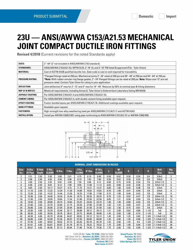
11910 CR 492 / Tyler, TX 75706 / (800) 527-84781501 West 17th St. / Anniston, AL 36201 / (800) 226-76011001 El Camino Ave. / Corona, CA 92879 / (866) 527-8471
Portland, OR 97203New Lenox, IL 60451
Grand Prairie, TX 75050Anniston, AL 36207
Elmer, NJ 08318Lithia Springs, GA 30122
SIZES: 2"–64" (2" not included in ANSI/AWWA C153 standard).
STANDARDS: ANSI/AWWA C153/A21.53, NFPA13/24, 3"-16" UL and 3"-10" FM listed & approved (File - Tyler Union).
MATERIAL: Cast of ASTM A536 qualified ductile iron. Date code is cast on and required for traceability.
PRESSURE RATING:*Flanged fittings rated at 250 psi. Mechanical joints 2"–24" rated at 350 psi and 30"–48" at 250 psi and 54"–64" at 150 psi. *Note: With rubber annular ring flange gasket, 2"–24" Flanged fittings can be rated at 350 psi. Note: Wyes over 12" are not pressure rated. Contact Tyler Union for rating in your application.
DEFLECTION: Joint deflection 5° max for 2"–12" and 3° max for 14"–48". Reduces by 50% at nominal pipe & fitting diameters.
NSF-61 & NSF372: Meets all requirements, including Annex G, Tyler Union’s Underwriters Laboratory listing MH16439.
ASPHALT COATING: Per ANSI/AWWA C104/A21.4 and ANSI/AWWA C153/A21.53.
CEMENT LINING: Per ANSI/AWWA C104/A21.4, with double cement lining available upon request.
EPOXY COATING: Fusion-bonded epoxy per ANSI/AWWA C116/A21.16. Additional coatings available upon request.
BARE FITTINGS: Available upon request.
FASTENERS: High-strength low-alloy weathering steel per ANSI/AWWA C111/A21.11 and ASTM A242.
INSTALLATION: Install per AWWA C600/C651 using pipe conforming to ANSI/AWWA C151/A21.51 or AWWA C900/905.
PRODUCT SUBMITTAL
NOMINAL JOINT DIMENSIONS IN INCHES
Size (In.)
A Dia. DI Pipe
B Hub Depth
C Dia. GLAND
D Dia. F Dia.J Dia.
GLANDK1 Dia.
K2 Dia. GLAND
LM
GLANDS T X
BoltSize
Qty.Bolts
2 2.51 2.50 3.50 3.60 2.61 4.75 6.19 6.89 0.58 0.62 0.36 0.30 3/4 5/8x3 23 3.96 2.50 4.84 4.94 4.06 6.19 7.62 7.69 0.58 0.62 0.39 0.33 3/4 5/8x3 44 4.80 2.50 5.92 6.02 4.90 7.50 9.06 9.12 0.60 0.75 0.39 0.34 7/8 3/4x3-1/2 46 6.90 2.50 8.02 8.12 7.00 9.50 11.06 11.12 0.63 0.88 0.43 0.36 7/8 3/4x3-1/2 68 9.05 2.50 10.17 10.27 9.15 11.75 13.31 13.37 0.66 1.00 0.45 0.38 7/8 3/4x4 6
10 11.10 2.50 12.22 12.34 11.20 14.00 15.62 15.62 0.70 1.00 0.47 0.40 7/8 3/4x4 812 13.20 2.50 14.32 14.44 13.30 16.25 17.88 17.88 0.73 1.00 0.49 0.42 7/8 3/4x4 814 15.30 3.50 16.40 16.54 15.44 18.75 20.25 20.25 0.79 1.25 0.55 0.47 7/8 3/4x4-1/2 1016 17.40 3.50 18.50 18.64 17.54 21.00 22.50 22.50 0.85 1.31 0.58 0.50 7/8 3/4x4-1/2 1218 19.50 3.50 20.60 20.74 19.64 23.25 24.83 24.75 1.00 1.38 0.68 0.54 7/8 3/4x4-1/2 1220 21.60 3.50 22.70 22.84 21.74 25.50 27.08 27.00 1.02 1.44 0.69 0.57 7/8 3/4x4-1/2 1424 25.80 3.50 26.90 27.04 25.94 30.00 31.58 31.50 1.02 1.56 0.75 0.61 7/8 3/4x5 1630 32.00 4.00 33.29 33.46 32.17 36.88 39.12 39.12 1.31 2.00 0.82 0.66 1-1/8 1x6 2036 38.30 4.00 39.59 39.76 38.47 43.75 46.00 46.00 1.45 2.00 1.00 0.74 1-1/8 1x6 2442 44.50 4.00 45.79 45.96 44.67 50.62 53.12 53.12 1.45 2.00 1.25 0.82 1-3/8 1-1/4x6-1/2 2848 50.80 4.00 52.09 52.26 50.97 57.50 60.00 60.00 1.45 2.00 1.35 0.90 1-3/8 1-1/4x6-1/2 3254 57.56 4.00 58.82 59.02 57.73 63.20 65.70 65.70 1.55 2.00 1.45 0.9 1-3/8 1-1/4x6-1/2 3660 61.61 4.00 62.87 63.07 61.78 67.72 70.22 70.22 1.75 2.00 1.50 0.94 1-3/8 1-1/4x6-1/2 3664 65.67 4.00 66.96 67.13 65.84 71.86 74.36 74.36 1.75 2.00 1.50 0.99 1-3/8 1-1/4x6-1/2 38
Revised 4/2018 (Current revisions for the noted Standards apply)
23U — ANSI/AWWA C153/A21.53 MECHANICAL JOINT COMPACT DUCTILE IRON FITTINGS
Domestic Import

11910 CR 492 / Tyler, TX 75706 / (800) 527-84781501 West 17th St. / Anniston, AL 36201 / (800) 226-76011001 El Camino Ave. / Corona, CA 92879 / (866) 527-8471
Portland, OR 97203New Lenox, IL 60451
Grand Prairie, TX 75050Anniston, AL 36207
Elmer, NJ 08318Lithia Springs, GA 30122
SIZES: 6”–12” PVC/ductile pipe per ANSI/AWWA C900 or C151 and cast iron pipe as provided. Comes with 4”–12” side flanged outlet & 3/4“ tap on the branch.
STANDARDS:Mechanical and *Flanged joints comply with applicable requirements of ANSI/AWWA C153/21.53 and ASME/ANSI B16.1. Ductile iron Mechanical Joint Tapping Sleeves are produced in accordance with Tyler Union manufacturer’s standard. *Note: Recess dimensions are per manufacturer’s standardization society standard practice SP-60. Meets the requirements of MSS SP-111.
MATERIAL: Cast of ASTM A536 qualified ductile iron. Date code is cast on and required for traceability.
PRESSURE RATING: Rated at 250 psi.
DEFLECTION: Deflection is not recommended.
GASKETS: SBR Mechanical Joint and Split gaskets are per ASTM D2000 – AA and ANSI/AWWA C111/21.11, armor tipped with coiled brass wire spring.
NSF-61 & NSF372: Meets all requirements, including Annex G, Tyler Union’s Underwriters Laboratory listing MH16439.
ASPHALT COATING: Per ANSI/AWWA C104/A21.4 and ANSI/AWWA C153/A21.53.
CEMENT LINING: Tapping Sleeves are unlined to ensure they fit over the pipe being tapped.
FLANGE: ASME/ANSI B16.1, Class 125.
FASTENERS: High-strength low-alloy weathering steel per ANSI/AWWA C111/A21.11 and ASTM A242.
INSTALLATION: Install per Tyler Union instructions below.
PRODUCT SUBMITTAL
INSTALLATION1. Clean pipe, insert side gasket into back half of gasket grooves. Make
sure ends are flush with or slightly protrude into the end gasket seating area.
2. Bolt sleeve halves together and trim side gaskets, as necessary. MAKE SURE SLEEVE WILL ROTATE FREELY ON PIPE.
3. Install end gaskets, locating cut ends 90° from side gasket. If pipe is maximum OD, stretch gasket to make certain cut ends match with no gap in between.
4. Install glands and bolts — rotate sleeve to desired position. Be sure pipe is centered inside the sleeve.
5. Tighten gland bolts alternately, using 80 to 90 ft-lb.
6. After assembly, pressure test all joints before tapping. If additional tightening is required, release pressure and relax tension on gland bolts before tightening side bolts.
Domestic Import
Revised 3/2017 (Current revisions for the noted Standards apply)
24U — MECHANICAL JOINT TAPPING SLEEVE FOR DUCTILE IRON, CAST IRON AND C900 PVC
NOMINAL JOINT DIMENSIONS IN INCHES
Size (In.)
A B C D E F PIPE OD RANGE DI
6x4 5.016 0.250 7.50 15.75 8.00 12.75 6.85 - 7.15 1046 7.016 0.312 9.50 15.75 8.00 12.75 6.85 - 7.15 108
8x4 5.016 0.250 7.50 16.50 9.00 13.38 9.00-9.35 1348x6 7.016 0.312 9.50 16.50 9.00 13.38 9.00-9.35 140
8 9.016 0.312 11.75 16.50 9.00 13.38 9.00-9.35 14810x4 5.016 0.250 7.50 24.00 11.00 20.75 11.04-11.45 23610x6 7.016 0.312 9.50 24.00 11.00 20.75 11.04-11.45 24010x8 9.016 0.312 11.75 24.00 11.00 20.75 11.04-11.45 246
10 11.016 0.312 14.25 24.00 11.00 20.75 11.04-11.45 25712x4 5.016 0.250 7.50 26.50 12.00 23.25 13.14-13.56 27312x6 7.016 0.312 9.50 26.50 12.00 23.25 13.14-13.56 28612x8 9.016 0.312 11.75 26.50 12.00 23.25 13.14-13.56 29212x10 11.016 0.312 14.25 26.50 12.00 23.25 13.14-13.56 303
12 13.016 0.312 17.00 26.50 12.00 23.25 13.14-13.56 320
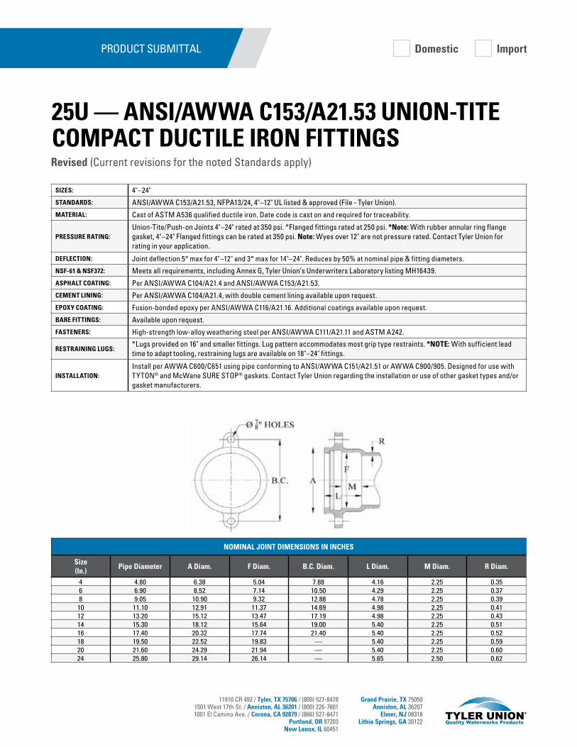
11910 CR 492 / Tyler, TX 75706 / (800) 527-84781501 West 17th St. / Anniston, AL 36201 / (800) 226-76011001 El Camino Ave. / Corona, CA 92879 / (866) 527-8471
Portland, OR 97203New Lenox, IL 60451
Grand Prairie, TX 75050Anniston, AL 36207
Elmer, NJ 08318Lithia Springs, GA 30122
SIZES: 4"–24"
STANDARDS: ANSI/AWWA C153/A21.53, NFPA13/24, 4"–12" UL listed & approved (File - Tyler Union).
MATERIAL: Cast of ASTM A536 qualified ductile iron. Date code is cast on and required for traceability.
PRESSURE RATING:Union-Tite/Push-on Joints 4"–24" rated at 350 psi. *Flanged fittings rated at 250 psi. *Note: With rubber annular ring flange gasket, 4"–24" Flanged fittings can be rated at 350 psi. Note: Wyes over 12" are not pressure rated. Contact Tyler Union for rating in your application.
DEFLECTION: Joint deflection 5° max for 4"–12" and 3° max for 14"–24". Reduces by 50% at nominal pipe & fitting diameters.
NSF-61 & NSF372: Meets all requirements, including Annex G, Tyler Union’s Underwriters Laboratory listing MH16439.
ASPHALT COATING: Per ANSI/AWWA C104/A21.4 and ANSI/AWWA C153/A21.53.
CEMENT LINING: Per ANSI/AWWA C104/A21.4, with double cement lining available upon request.
EPOXY COATING: Fusion-bonded epoxy per ANSI/AWWA C116/A21.16. Additional coatings available upon request.
BARE FITTINGS: Available upon request.
FASTENERS: High-strength low-alloy weathering steel per ANSI/AWWA C111/A21.11 and ASTM A242.
RESTRAINING LUGS:*Lugs provided on 16" and smaller fittings. Lug pattern accommodates most grip type restraints. *NOTE: With sufficient lead time to adapt tooling, restraining lugs are available on 18"–24" fittings.
INSTALLATION:Install per AWWA C600/C651 using pipe conforming to ANSI/AWWA C151/A21.51 or AWWA C900/905. Designed for use with TYTON® and McWane SURE STOP® gaskets. Contact Tyler Union regarding the installation or use of other gasket types and/or gasket manufacturers.
PRODUCT SUBMITTAL
NOMINAL JOINT DIMENSIONS IN INCHES
Size (In.)
Pipe Diameter A Diam. F Diam. B.C. Diam. L Diam. M Diam. R Diam.
4 4.80 6.38 5.04 7.88 4.16 2.25 0.356 6.90 8.52 7.14 10.50 4.29 2.25 0.378 9.05 10.90 9.32 12.88 4.78 2.25 0.39
10 11.10 12.91 11.37 14.69 4.98 2.25 0.4112 13.20 15.12 13.47 17.19 4.98 2.25 0.4314 15.30 18.12 15.64 19.00 5.40 2.25 0.5116 17.40 20.32 17.74 21.40 5.40 2.25 0.5218 19.50 22.52 19.83 — 5.40 2.25 0.5920 21.60 24.29 21.94 — 5.40 2.25 0.6024 25.80 29.14 26.14 — 5.65 2.50 0.62
Domestic Import
Revised (Current revisions for the noted Standards apply)
25U — ANSI/AWWA C153/A21.53 UNION-TITE COMPACT DUCTILE IRON FITTINGS
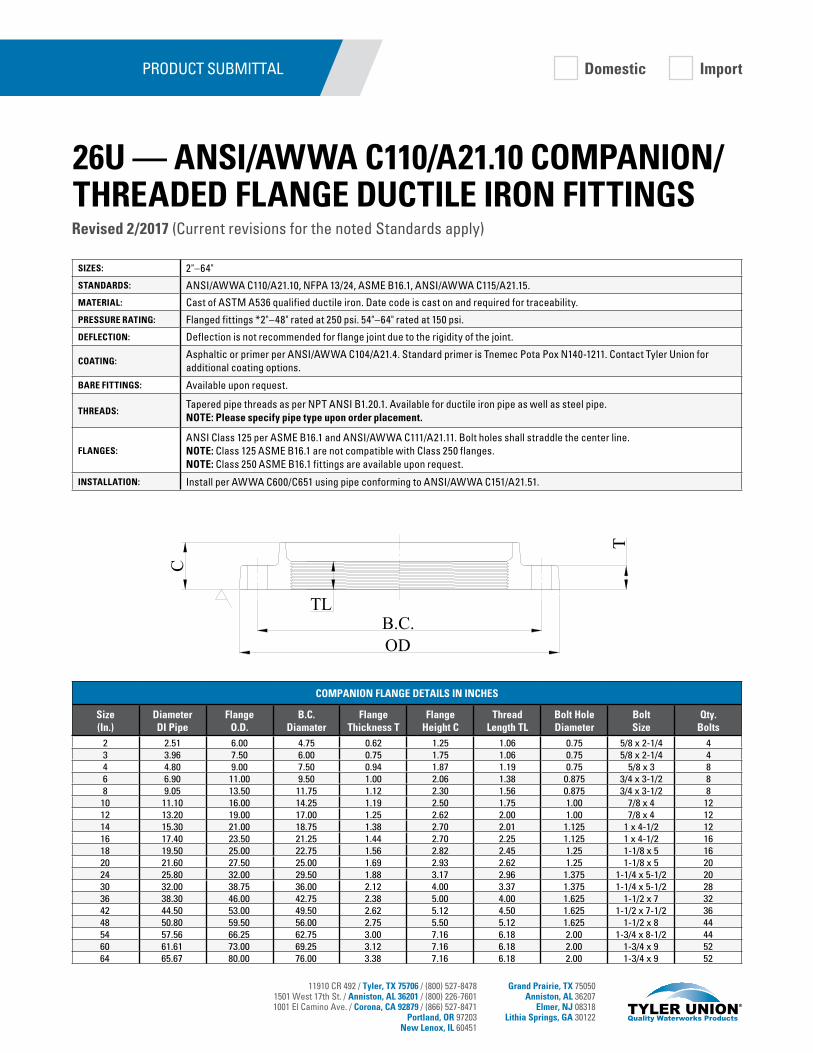
11910 CR 492 / Tyler, TX 75706 / (800) 527-84781501 West 17th St. / Anniston, AL 36201 / (800) 226-76011001 El Camino Ave. / Corona, CA 92879 / (866) 527-8471
Portland, OR 97203New Lenox, IL 60451
Grand Prairie, TX 75050Anniston, AL 36207
Elmer, NJ 08318Lithia Springs, GA 30122
SIZES: 2"–64"
STANDARDS: ANSI/AWWA C110/A21.10, NFPA 13/24, ASME B16.1, ANSI/AWWA C115/A21.15.
MATERIAL: Cast of ASTM A536 qualified ductile iron. Date code is cast on and required for traceability.
PRESSURE RATING: Flanged fittings *2"–48" rated at 250 psi. 54"–64" rated at 150 psi.
DEFLECTION: Deflection is not recommended for flange joint due to the rigidity of the joint.
COATING:Asphaltic or primer per ANSI/AWWA C104/A21.4. Standard primer is Tnemec Pota Pox N140-1211. Contact Tyler Union for additional coating options.
BARE FITTINGS: Available upon request.
THREADS:Tapered pipe threads as per NPT ANSI B1.20.1. Available for ductile iron pipe as well as steel pipe. NOTE: Please specify pipe type upon order placement.
FLANGES:ANSI Class 125 per ASME B16.1 and ANSI/AWWA C111/A21.11. Bolt holes shall straddle the center line.NOTE: Class 125 ASME B16.1 are not compatible with Class 250 flanges.NOTE: Class 250 ASME B16.1 fittings are available upon request.
INSTALLATION: Install per AWWA C600/C651 using pipe conforming to ANSI/AWWA C151/A21.51.
PRODUCT SUBMITTAL
B.C.T
C
TL
OD
COMPANION FLANGE DETAILS IN INCHES
Size (In.)
Diameter DI Pipe
Flange O.D.
B.C. Diamater
Flange Thickness T
Flange Height C
Thread Length TL
Bolt Hole Diameter
BoltSize
Qty.Bolts
2 2.51 6.00 4.75 0.62 1.25 1.06 0.75 5/8 x 2-1/4 43 3.96 7.50 6.00 0.75 1.75 1.06 0.75 5/8 x 2-1/4 44 4.80 9.00 7.50 0.94 1.87 1.19 0.75 5/8 x 3 86 6.90 11.00 9.50 1.00 2.06 1.38 0.875 3/4 x 3-1/2 88 9.05 13.50 11.75 1.12 2.30 1.56 0.875 3/4 x 3-1/2 8
10 11.10 16.00 14.25 1.19 2.50 1.75 1.00 7/8 x 4 1212 13.20 19.00 17.00 1.25 2.62 2.00 1.00 7/8 x 4 1214 15.30 21.00 18.75 1.38 2.70 2.01 1.125 1 x 4-1/2 1216 17.40 23.50 21.25 1.44 2.70 2.25 1.125 1 x 4-1/2 1618 19.50 25.00 22.75 1.56 2.82 2.45 1.25 1-1/8 x 5 1620 21.60 27.50 25.00 1.69 2.93 2.62 1.25 1-1/8 x 5 2024 25.80 32.00 29.50 1.88 3.17 2.96 1.375 1-1/4 x 5-1/2 2030 32.00 38.75 36.00 2.12 4.00 3.37 1.375 1-1/4 x 5-1/2 2836 38.30 46.00 42.75 2.38 5.00 4.00 1.625 1-1/2 x 7 3242 44.50 53.00 49.50 2.62 5.12 4.50 1.625 1-1/2 x 7-1/2 3648 50.80 59.50 56.00 2.75 5.50 5.12 1.625 1-1/2 x 8 4454 57.56 66.25 62.75 3.00 7.16 6.18 2.00 1-3/4 x 8-1/2 4460 61.61 73.00 69.25 3.12 7.16 6.18 2.00 1-3/4 x 9 5264 65.67 80.00 76.00 3.38 7.16 6.18 2.00 1-3/4 x 9 52
Revised 2/2017 (Current revisions for the noted Standards apply)
26U — ANSI/AWWA C110/A21.10 COMPANION/THREADED FLANGE DUCTILE IRON FITTINGS
Domestic Import
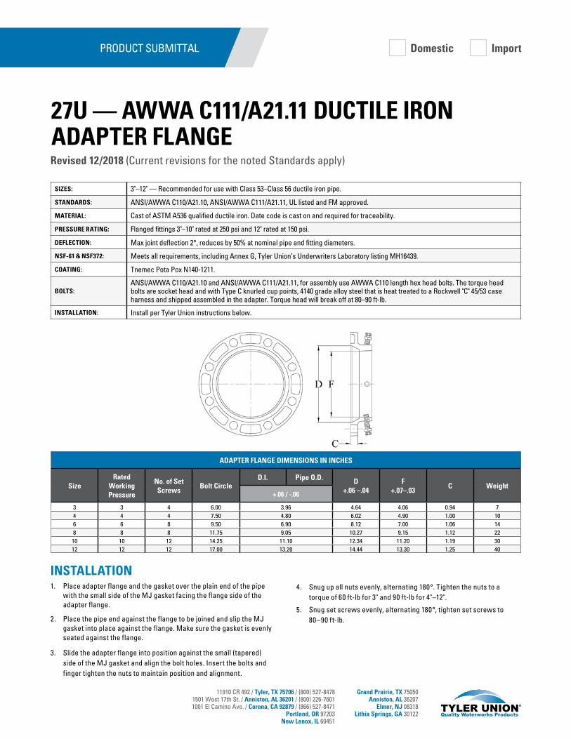
11910 CR 492 / Tyler, TX 75706 / (800) 527-84781501 West 17th St. / Anniston, AL 36201 / (800) 226-76011001 El Camino Ave. / Corona, CA 92879 / (866) 527-8471
Portland, OR 97203New Lenox, IL 60451
Grand Prairie, TX 75050Anniston, AL 36207
Elmer, NJ 08318Lithia Springs, GA 30122
SIZES: 3"–12" — Recommended for use with Class 53–Class 56 ductile iron pipe.
STANDARDS: ANSI/AWWA C110/A21.10, ANSI/AWWA C111/A21.11, UL listed and FM approved.
MATERIAL: Cast of ASTM A536 qualified ductile iron. Date code is cast on and required for traceability.
PRESSURE RATING: Flanged fittings 3"–10" rated at 250 psi and 12" rated at 150 psi.
DEFLECTION: Max joint deflection 2°, reduces by 50% at nominal pipe and fitting diameters.
NSF-61 & NSF372: Meets all requirements, including Annex G, Tyler Union’s Underwriters Laboratory listing MH16439.
COATING: Tnemec Pota Pox N140-1211.
BOLTS:ANSI/AWWA C110/A21.10 and ANSI/AWWA C111/A21.11, for assembly use AWWA C110 length hex head bolts. The torque head bolts are socket head and with Type C knurled cup points, 4140 grade alloy steel that is heat treated to a Rockwell "C" 45/53 case harness and shipped assembled in the adapter. Torque head will break off at 80–90 ft-lb.
INSTALLATION: Install per Tyler Union instructions below.
PRODUCT SUBMITTAL
INSTALLATION1. Place adapter flange and the gasket over the plain end of the pipe
with the small side of the MJ gasket facing the flange side of the adapter flange.
2. Place the pipe end against the flange to be joined and slip the MJ gasket into place against the flange. Make sure the gasket is evenly seated against the flange.
3. Slide the adapter flange into position against the small (tapered) side of the MJ gasket and align the bolt holes. Insert the bolts and finger tighten the nuts to maintain position and alignment.
4. Snug up all nuts evenly, alternating 180°. Tighten the nuts to a torque of 60 ft-lb for 3" and 90 ft-lb for 4"–12".
5. Snug set screws evenly, alternating 180°, tighten set screws to 80–90 ft-lb.
Domestic Import
Revised 12/2018 (Current revisions for the noted Standards apply)
27U — AWWA C111/A21.11 DUCTILE IRON ADAPTER FLANGE
ADAPTER FLANGE DIMENSIONS IN INCHES
SizeRated
Working Pressure
No. of Set Screws
Bolt CircleD.I. Pipe O.D. D
+.06 –.04F
+.07–.03C Weight
+.06 / -.06
3 3 4 6.00 3.96 4.64 4.06 0.94 74 4 4 7.50 4.80 6.02 4.90 1.00 106 6 8 9.50 6.90 8.12 7.00 1.06 148 8 8 11.75 9.05 10.27 9.15 1.12 22
10 10 12 14.25 11.10 12.34 11.20 1.19 3012 12 12 17.00 13.20 14.44 13.30 1.25 40

11910 CR 492 / Tyler, TX 75706 / (800) 527-84781501 West 17th St. / Anniston, AL 36201 / (800) 226-76011001 El Camino Ave. / Corona, CA 92879 / (866) 527-8471
Portland, OR 97203New Lenox, IL 60451
Grand Prairie, TX 75050Anniston, AL 36207
Elmer, NJ 08318Lithia Springs, GA 30122
SIZES: 2"–64"
STANDARDS: ANSI/AWWA C110/A21.10, NFPA 13/24, ASME B16.1, 3"–12" UL listed and FM approved.
MATERIAL: Cast of ASTM A536 qualified ductile iron. Date code is cast on and required for traceability.
PRESSURE RATING: *Flanged fittings *2"–48" rated at 250 psi. 54"–64" rated at 150psi. *Note: With rubber annular ring flange gasket, 2"–24" flanged fittings can be rated at 350 psi.
DEFLECTION: Deflection is not recommended for flange joint due to the rigidity of the joint.
NSF-61 & NSF372: Meets all requirements, including Annex G, Tyler Union’s UnderwritersLaboratory listing MH16439.
COATING: Asphaltic or Primer per ANSI/AWWA C104/A21.4, Standard primer is Tnemec Pota Pox N140-1211. Contact Tyler Union for additional coating options.
CEMENT LINING: Per ANSI/AWWA C104/A21.4, with double cement lining available upon request.
EPOXY COATING: Fusion-bonded epoxy per ANSI/AWWA C116/A21.16. Additional coatings available upon request.
BARE FITTINGS: Available upon request.
FLANGES:
ANSI Class 125 per ASME B16.1 and ANSI/AWWA C111/A21.11. Bolt holes shall straddle the center line.NOTE: Class 125 ASME B16.1 are not compatible with Class 250 Flanges.NOTE: Class 250 ASME B16.1 fittings are available upon request.
FASTENERS: High-strength low-alloy weathering steel per ANSI/AWWA C111/A21.11 and ASTM A242.
INSTALLATION: Install per AWWA C600/C651 using pipe conforming to ANSI/AWWA C151/A21.51.
PRODUCT SUBMITTAL Domestic Import
Revised 3/2017 (Current revisions for the noted Standards apply)
28U — ANSI/AWWA C110/A21.10 C110 FLANGE JOINT CLASS 125 PRODUCT
FLANGE DETAILS IN INCHES
Size (In.)
Diameter DI Pipe
Flange O.D.
B.C. Diameter
Flange Thickness T
Bolt Hole Diameter
BoltSize
Qty.Bolts
2 2.51 6.00 4.75 0.62 0.750 5/8 x 2-1/4 43 3.96 7.50 6.00 0.75 0.750 5/8 x 2-1/4 44 4.80 9.00 7.50 0.94 0.750 5/8 x 3 86 6.90 11.00 9.50 1.00 0.875 3/4 x 3-1/2 88 9.05 13.50 11.75 1.12 0.875 3/4 x 3-1/2 8
10 11.10 16.00 14.25 1.19 1.000 7/8 x 4 1212 13.20 19.00 17.00 1.25 1.000 7/8 x 4 1214 15.30 21.00 18.75 1.38 1.125 1 x 4-1/2 1216 17.40 23.50 21.25 1.44 1.125 1 x 4-1/2 1618 19.50 25.00 22.75 1.56 1.250 1-1/8 x 5 1620 21.60 27.50 25.00 1.69 1.250 1-1/8 x 5 2024 25.80 32.00 29.50 1.88 1.375 1-1/4 x 5-1/2 2030 32.00 38.75 36.00 2.12 1.375 1-1/4 x 5-1/2 2836 38.30 46.00 42.75 2.38 1.625 1-1/2 x 7 3242 44.50 53.00 49.50 2.62 1.625 1-1/2 x 7-1/2 3648 50.80 59.50 56.00 2.75 1.625 1-1/2 x 8 4454 57.56 66.25 62.75 3.00 2.000 1-3/4 x 8-1/2 4460 61.61 73.00 69.25 3.12 2.000 1-3/4 x 9 5264 65.67 80.00 76.00 3.38 2.000 1-3/4 x 9 52
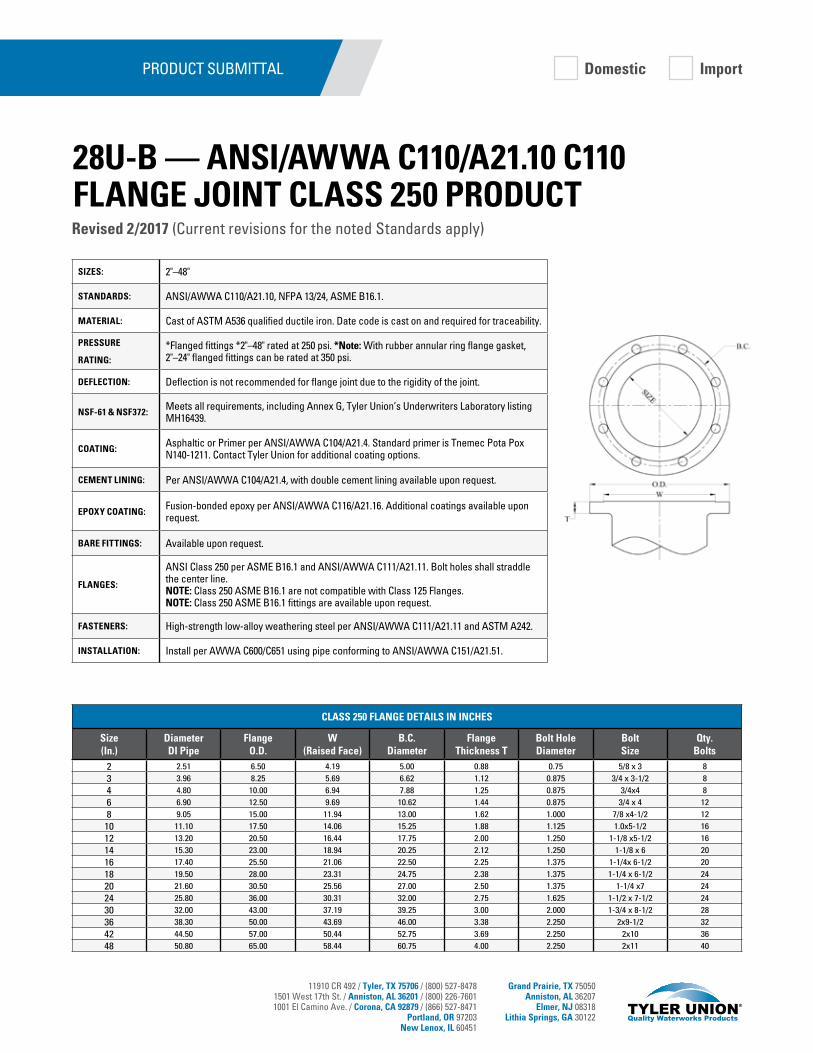
11910 CR 492 / Tyler, TX 75706 / (800) 527-84781501 West 17th St. / Anniston, AL 36201 / (800) 226-76011001 El Camino Ave. / Corona, CA 92879 / (866) 527-8471
Portland, OR 97203New Lenox, IL 60451
Grand Prairie, TX 75050Anniston, AL 36207
Elmer, NJ 08318Lithia Springs, GA 30122
SIZES: 2"–48"
STANDARDS: ANSI/AWWA C110/A21.10, NFPA 13/24, ASME B16.1.
MATERIAL: Cast of ASTM A536 qualified ductile iron. Date code is cast on and required for traceability.
PRESSURE
RATING:
*Flanged fittings *2"–48" rated at 250 psi. *Note: With rubber annular ring flange gasket, 2"–24" flanged fittings can be rated at 350 psi.
DEFLECTION: Deflection is not recommended for flange joint due to the rigidity of the joint.
NSF-61 & NSF372: Meets all requirements, including Annex G, Tyler Union’s Underwriters Laboratory listing MH16439.
COATING: Asphaltic or Primer per ANSI/AWWA C104/A21.4. Standard primer is Tnemec Pota Pox N140-1211. Contact Tyler Union for additional coating options.
CEMENT LINING: Per ANSI/AWWA C104/A21.4, with double cement lining available upon request.
EPOXY COATING: Fusion-bonded epoxy per ANSI/AWWA C116/A21.16. Additional coatings available upon request.
BARE FITTINGS: Available upon request.
FLANGES:
ANSI Class 250 per ASME B16.1 and ANSI/AWWA C111/A21.11. Bolt holes shall straddle the center line.NOTE: Class 250 ASME B16.1 are not compatible with Class 125 Flanges.NOTE: Class 250 ASME B16.1 fittings are available upon request.
FASTENERS: High-strength low-alloy weathering steel per ANSI/AWWA C111/A21.11 and ASTM A242.
INSTALLATION: Install per AWWA C600/C651 using pipe conforming to ANSI/AWWA C151/A21.51.
PRODUCT SUBMITTAL Domestic Import
Revised 2/2017 (Current revisions for the noted Standards apply)
28U-B — ANSI/AWWA C110/A21.10 C110 FLANGE JOINT CLASS 250 PRODUCT
CLASS 250 FLANGE DETAILS IN INCHES
Size (In.)
Diameter DI Pipe
Flange O.D.
W (Raised Face)
B.C. Diameter
Flange Thickness T
Bolt Hole Diameter
BoltSize
Qty.Bolts
2 2.51 6.50 4.19 5.00 0.88 0.75 5/8 x 3 83 3.96 8.25 5.69 6.62 1.12 0.875 3/4 x 3-1/2 84 4.80 10.00 6.94 7.88 1.25 0.875 3/4x4 86 6.90 12.50 9.69 10.62 1.44 0.875 3/4 x 4 128 9.05 15.00 11.94 13.00 1.62 1.000 7/8 x4-1/2 12
10 11.10 17.50 14.06 15.25 1.88 1.125 1.0x5-1/2 1612 13.20 20.50 16.44 17.75 2.00 1.250 1-1/8 x5-1/2 1614 15.30 23.00 18.94 20.25 2.12 1.250 1-1/8 x 6 2016 17.40 25.50 21.06 22.50 2.25 1.375 1-1/4x 6-1/2 2018 19.50 28.00 23.31 24.75 2.38 1.375 1-1/4 x 6-1/2 2420 21.60 30.50 25.56 27.00 2.50 1.375 1-1/4 x7 2424 25.80 36.00 30.31 32.00 2.75 1.625 1-1/2 x 7-1/2 2430 32.00 43.00 37.19 39.25 3.00 2.000 1-3/4 x 8-1/2 2836 38.30 50.00 43.69 46.00 3.38 2.250 2x9-1/2 3242 44.50 57.00 50.44 52.75 3.69 2.250 2x10 3648 50.80 65.00 58.44 60.75 4.00 2.250 2x11 40

11910 CR 492 / Tyler, TX 75706 / (800) 527-84781501 West 17th St. / Anniston, AL 36201 / (800) 226-76011001 El Camino Ave. / Corona, CA 92879 / (866) 527-8471
Portland, OR 97203New Lenox, IL 60451
Grand Prairie, TX 75050Anniston, AL 36207
Elmer, NJ 08318Lithia Springs, GA 30122
SIZES: 5/8 x 3 through 1-1/4 x 8-1/2.
STANDARDS: ANSI/AWWA C111/A21.11.
MATERIAL: ASTM A242 high-strength low-alloy steel. Also available in ANSI 304 or ANSI 316 AISI Stainless Steel.
COATING: Standard nuts and bolts are not coated. Flouropolymer coating is available upon request. Flouropolymer is Fluorokote #1 (blue for low alloy steel).
FASTENERS: High-strength low-alloy weathering steel per ANSI/AWWA C111/A21.11 and ASTM A242.
PRODUCT SUBMITTAL
Revised 2/2017 (Current revisions for the noted Standards apply)
Domestic Import
29U — BOLTS AND NUTS FOR MECHANICAL JOINTS
NOMINAL JOINT DIMENSIONS IN INCHES
Size (In.)
A ± 0.05
B +0.03 / -0.074
C+0.25 / -0.06
F HJ
+0.15 / -0.03R Max D*
Threads Per Inch E**
5/8 x 3 1.5 0.625 3.00 0.625 1.062 0.625 0.312 2.00 113/4 x 3-1/2 1.75 0.750 3.50 0.750 1.250 0.750 0.375 2.50 10
3/4 x 4 1.75 0.750 4.00 0.750 1.250 0.750 0.375 3.00 103/4 x 4-1/2 1.75 0.750 4.50 0.750 1.250 0.750 0.375 3.00 10
3/4 x 5 1.75 0.750 5.00 0.750 1.250 0.750 0.375 3.00 101 x 6 1.75 1.000 6.00 1.000 1.625 1.000 0.500 3.00 8
1 x 7-1/2 2.25 1.000 7.50 1.000 1.625 1.000 0.625 4.50 81-1/4 x 6-1/2 2.50 1.250 6.50 1.250 2.000 1.250 0.750 3.50 71-1/4 x 8-1/2 2.50 1.250 8.50 1.250 2.000 1.250 0.750 4.00 7
NOTES:
1. Dimension B is unthreaded shank.
2. Draft, when required to be 6° maximum, may be deducted from bolt head dimensions, and radius may be changed to suit draft.
3. Gates, if required, may protrude a maximum of 1/8” above the top of the bolt head.
4. Chamfer is optional if threads are rolled.
5. If threads are rolled, the body diameter may be reduced to the approximate pitch diameter of the thread.
Note: Tolerance +3/-0 thread.Note: Number of threads per inch — coarse-thread series (ANSI/ASME B1.1), class 2A, external fit UNC2A and class 2B, UNC2B (ANSI/ASME B1.2).(3) If seal coat paint is used during field repair, allow a cure time of 48 hours after the seal coat is applied before placing fitting back in service.
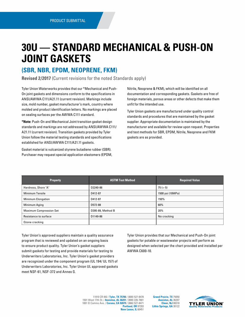
11910 CR 492 / Tyler, TX 75706 / (800) 527-84781501 West 17th St. / Anniston, AL 36201 / (800) 226-76011001 El Camino Ave. / Corona, CA 92879 / (866) 527-8471
Portland, OR 97203New Lenox, IL 60451
Grand Prairie, TX 75050Anniston, AL 36207
Elmer, NJ 08318Lithia Springs, GA 30122
Tyler Union Waterworks provides that our *Mechanical and Push-On joint gaskets and dimensions conform to the specifications in ANSI/AWWA C111/A21.11 (current revision). Markings include size, mold number, gasket manufacturer’s mark, country where molded and product identification letters. No markings are placed on sealing surfaces per the AWWA C111 standard.
*Note: Push-On and Mechanical Joint transition gasket design standards and markings are not addressed by ANSI/AWWA C111/A21.11 (current revision). Transition gaskets provided by Tyler Union follow the material testing standards and specifications established for ANSI/AWWA C111/A21.11 gaskets.
Gasket material is vulcanized styrene butadiene rubber (SBR). Purchaser may request special application elastomers (EPDM,
Nitrile, Neoprene & FKM), which will be identified on all documentation and corresponding gaskets. Gaskets are free of foreign materials, porous areas or other defects that make them unfit for the intended use.
Tyler Union gaskets are manufactured under quality control standards and procedures that are maintained by the gasket supplier. Appropriate documentation is maintained by the manufacturer and available for review upon request. Properties and test methods for SBR, EPDM, Nitrile, Neoprene and FKM gaskets are as provided.
Tyler Union’s approved suppliers maintain a quality assurance program that is reviewed and updated on an ongoing basis to ensure product quality. Tyler Union’s gasket suppliers submit gaskets for testing and provide materials for testing to Underwriters Laboratories, Inc. Tyler Union’s gasket providers are recognized under the component program (UL 194/ UL 157) of Underwriters Laboratories, Inc. Tyler Union UL approved gaskets meet NSF-61, NSF-372 and Annex G.
Tyler Union provides that our Mechanical and Push-On joint gaskets for potable or wastewater projects will perform as designed when selected per the chart provided and installed per AWWA C600-10.
(SBR, NBR, EPDM, NEOPRENE, FKM)Revised 2/2017 (Current revisions for the noted Standards apply)
Property ASTM Test Method Required Value
Hardness, Shore "A" D2240-86 75 (+-5)
Minimum Tensile D412-87 1500 psi (10MPa)
Minimum Elongation D412-87 150%
Minimum Aging D572-88 60%
Maximum Compression Set D395-89, Method B 20%
Resistance to surface D1149-86 No cracking
Ozone cracking
PRODUCT SUBMITTAL
30U — STANDARD MECHANICAL & PUSH-ON JOINT GASKETS

11910 CR 492 / Tyler, TX 75706 / (800) 527-84781501 West 17th St. / Anniston, AL 36201 / (800) 226-76011001 El Camino Ave. / Corona, CA 92879 / (866) 527-8471
Portland, OR 97203New Lenox, IL 60451
Grand Prairie, TX 75050Anniston, AL 36207
Elmer, NJ 08318Lithia Springs, GA 30122
30U — STANDARD MECHANICAL & PUSH-ON JOINT GASKETS (SBR, NBR, EPDM, NEOPRENE, FKM)Revised 2/2017
SBR (STYRENE BUTADIENE RUBBER) (BUNA-S)Not recommended for hydrocarbon service. 20°F to 180°F Suitable for water, wastewater, most moderate chemicals, wet or dry organic
acids, alcohols, ketones and aldehydes.
EPDM (ETHYLENE PROPYLENE) Not recommended for hydrocarbon service. -10°F to 250°F Ideal for water, wastewater, ozone and strong oxidizing chemicals. May be used on
steam and air within its temperature range.
CR (NEOPRENE) -10°F to 200°F Recommended for moderate chemicals and acids, oil fats, greases, many solvents and air with hydrocarbons. Will not support combustion.
NBR (NITRILE)(BUNA-N)(HYCAR) -40°F to 250°F Ideally suited for gasoline, petroleum products, hydrocarbons, water, mineral and vegetable oils.
*FKM (FLUOROELASTOMER)*Check with customer service for availability. 10°F to 425°F Ideally suited for hydrocarbons, acids, vegetable oils and petroleum.
GASKET TYPES OFFERED:(1) Mechanical Joint std. (2) Push-On Joint std. (3) Mechanical Joint DUO(4) Mechanical and Push-on Joint Transition (5) Push-on Restraining(6) Mechanical Joint Armor Tip Conductivity (7) Compact tapping Sleeve
NOTE: Unless other wise requested by the purchaser upon order placement, all gaskets provided will be of our standard SBR material.
PRODUCT SUBMITTAL
MECHANICAL JOINT GASKETS/ANSI/AWWA C111/A21.11-12/*MJ TRU-LOCK GASKETS 30"–48" INCH
Pipe Size (In.)
Pipe O.D.A
+0.01"B C D E F G
**2 2.50 0.48 0.62 0.31 2.48 0.12 0.15 1.053 3.96 0.48 0.62 0.31 3.86 0.12 0.15 1.054 4.80 0.62 0.75 0.31 4.68 0.16 0.22 1.226 6.90 0.62 0.75 0.31 6.73 0.16 0.22 1.228 9.05 0.62 0.75 0.31 8.85 0.16 0.22 1.2210 11.10 0.62 0.75 0.31 10.87 0.16 0.22 1.2212 13.20 0.62 0.75 0.31 12.95 0.16 0.22 1.2214 15.30 0.62 0.75 0.31 14.99 0.16 0.22 1.2216 17.40 0.62 0.75 0.31 17.07 0.16 0.22 1.2218 19.50 0.62 0.75 0.31 19.13 0.16 0.22 1.2220 21.60 0.62 0.75 0.31 21.20 0.16 0.22 1.2224 25.80 0.62 0.75 0.31 25.34 0.16 0.22 1.2230 32.00 0.73 1.00/*.50 .38/*.50 31.47 0.16 .37/*.55 1.54/*1.1636 38.30 0.73 1.00/*.50 .38/*.50 37.67 0.16 .37/*.55 1.54/*1.1642 44.50 0.73 1.00/*.50 .38/*.50 43.78 0.16 .37/*.55 1.54/*1.1648 50.80 0.73 1.00/*.50 .38/*.50 49.98 0.16 .37/*.55 1.54/*1.16
** Not included in AWWA C111. Manufacturer’s Standard does not meet AWWA C111.
** MECHANICAL JOINT TRANSITION GASKET DIMENSIONS IN INCHES
Pipe Size (In.)
A ± 0.01"
B CD
± 1%E
F± 0.01"
G± 0.02"
2 0.57 0.62 0.31 2.28 0.16 0.24 1.083 0.70 0.62 0.31 3.45 0.16 0.37 1.114 0.77 0.75 0.31 4.43 0.16 0.37 1.266 0.76 0.75 0.31 6.53 0.16 0.36 1.258 0.82 0.75 0.31 8.50 0.16 0.42 1.27
10 0.79 0.75 0.31 10.59 0.16 0.39 1.2612 0.84 0.75 0.31 12.56 0.16 0.44 1.28
** Not included in AWWA C111. Manufacturer’s Standard does not meet AWWA C111.
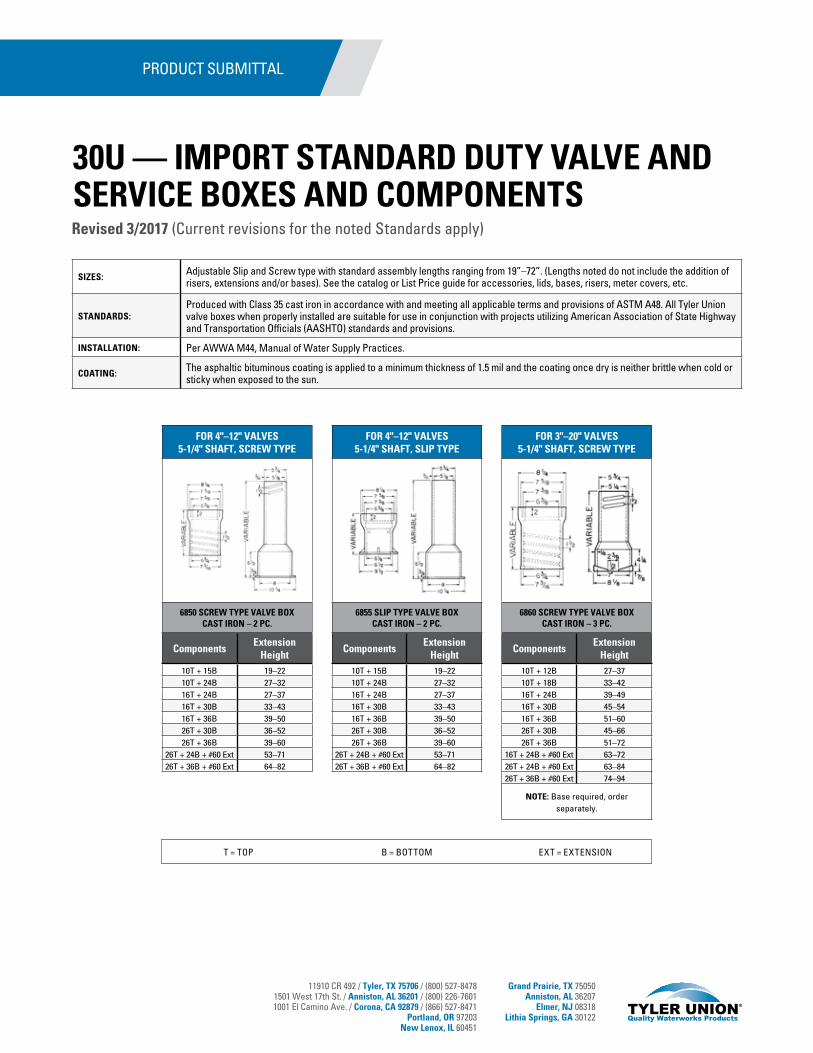
11910 CR 492 / Tyler, TX 75706 / (800) 527-84781501 West 17th St. / Anniston, AL 36201 / (800) 226-76011001 El Camino Ave. / Corona, CA 92879 / (866) 527-8471
Portland, OR 97203New Lenox, IL 60451
Grand Prairie, TX 75050Anniston, AL 36207
Elmer, NJ 08318Lithia Springs, GA 30122
SIZES: Adjustable Slip and Screw type with standard assembly lengths ranging from 19”–72”. (Lengths noted do not include the addition of risers, extensions and/or bases). See the catalog or List Price guide for accessories, lids, bases, risers, meter covers, etc.
STANDARDS:Produced with Class 35 cast iron in accordance with and meeting all applicable terms and provisions of ASTM A48. All Tyler Union valve boxes when properly installed are suitable for use in conjunction with projects utilizing American Association of State Highway and Transportation Officials (AASHTO) standards and provisions.
INSTALLATION: Per AWWA M44, Manual of Water Supply Practices.
COATING: The asphaltic bituminous coating is applied to a minimum thickness of 1.5 mil and the coating once dry is neither brittle when cold or sticky when exposed to the sun.
PRODUCT SUBMITTAL
FOR 4"–12" VALVES 5-1/4" SHAFT, SCREW TYPE
6850 SCREW TYPE VALVE BOX CAST IRON – 2 PC.
ComponentsExtension
Height10T + 15B 19–2210T + 24B 27–3216T + 24B 27–3716T + 30B 33–4316T + 36B 39–5026T + 30B 36–5226T + 36B 39–60
26T + 24B + #60 Ext 53–7126T + 36B + #60 Ext 64–82
FOR 4"–12" VALVES 5-1/4" SHAFT, SLIP TYPE
6855 SLIP TYPE VALVE BOX CAST IRON – 2 PC.
ComponentsExtension
Height10T + 15B 19–2210T + 24B 27–3216T + 24B 27–3716T + 30B 33–4316T + 36B 39–5026T + 30B 36–5226T + 36B 39–60
26T + 24B + #60 Ext 53–7126T + 36B + #60 Ext 64–82
FOR 3"–20" VALVES 5-1/4" SHAFT, SCREW TYPE
6860 SCREW TYPE VALVE BOX CAST IRON – 3 PC.
ComponentsExtension
Height10T + 12B 27–3710T + 18B 33–4216T + 24B 39–4916T + 30B 45–5416T + 36B 51–6026T + 30B 45–6626T + 36B 51–72
16T + 24B + #60 Ext 63–7226T + 24B + #60 Ext 63–8426T + 36B + #60 Ext 74–94
NOTE: Base required, order separately.
T = TOP B = BOTTOM EXT = EXTENSION
Revised 3/2017 (Current revisions for the noted Standards apply)
30U — IMPORT STANDARD DUTY VALVE AND SERVICE BOXES AND COMPONENTS
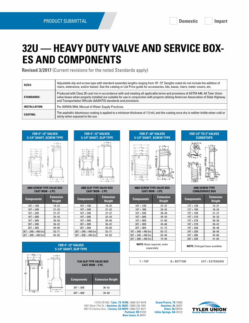
11910 CR 492 / Tyler, TX 75706 / (800) 527-84781501 West 17th St. / Anniston, AL 36201 / (800) 226-76011001 El Camino Ave. / Corona, CA 92879 / (866) 527-8471
Portland, OR 97203New Lenox, IL 60451
Grand Prairie, TX 75050Anniston, AL 36207
Elmer, NJ 08318Lithia Springs, GA 30122
SIZES:Adjustable slip and screw type with standard assembly lengths ranging from 19"–72" (lengths noted do not include the addition of risers, extensions, and/or bases). See the catalog or List Price guide for accessories, lids, bases, risers, meter covers, etc.
STANDARDS:Produced with Class 35 cast iron in accordance with and meeting all applicable terms and provisions of ASTM A48. All Tyler Union valve boxes when properly installed are suitable for use in conjunction with projects utilizing American Association of State Highway and Transportation Officials (AASHTO) standards and provisions.
INSTALLATION: Per AWWA M44, Manual of Water Supply Practices.
COATING: The asphaltic bituminous coating is applied to a minimum thickness of 1.5 mil, and the coating once dry is neither brittle when cold or sticky when exposed to the sun.
PRODUCT SUBMITTAL Domestic Import
FOR 4"–12" VALVES 5-1/4" SHAFT, SCREW TYPE
6850 SCREW TYPE VALVE BOX CAST IRON – 2 PC.
ComponentsExtension
Height10T + 15B 19–2210T + 24B 27–3216T + 24B 27–3716T + 30B 33–4316T + 36B 39–5026T + 30B 36–5226T + 36B 39–60
26T + 24B + #60 Ext 53–7126T + 36B + #60 Ext 64–82
FOR 4"–12" VALVES 5-1/4" SHAFT, SLIP TYPE
7126 SLIP TYPE VALVE BOX CAST IRON – 2 PC.
Components Extension Height
26T + 30B 36–52
26T + 36B 39–60
FOR 4"–12" VALVES 5-1/4" SHAFT, SLIP TYPE
6855 SLIP TYPE VALVE BOX CAST IRON – 2 PC.
ComponentsExtension
Height10T + 15B 19–2210T + 24B 27–3216T + 24B 27–3716T + 30B 33–4316T + 36B 39–5026T + 30B 36–5226T + 36B 39–60
26T + 24B + #60 Ext 53–7126T + 36B + #60 Ext 64–82
FOR 3"–20" VALVES 5-1/4" SHAFT, SCREW TYPE
6860 SCREW TYPE VALVE BOX CAST IRON – 3 PC.
ComponentsExtension
Height10T + 12B 27–3710T + 18B 33–4216T + 24B 39–4916T + 30B 45–5416T + 36B 51–6026T + 30B 45–6626T + 36B 51–72
16T + 24B + #60 Ext 63–7226T + 24B + #60 Ext 63–8426T + 36B + #60 Ext 74–94
NOTE: Base required, order separately
FOR 1/2" TO 2" VALVES CURBSTOPS
6500 SCREW TYPE CURB/SERVICE BOX
ComponentsExtension
Height12T + 12B 15–2112T + 15B 18–2415T + 15B 21–2715T + 21B 24–3315T + 27B 30–3918T + 27B 30–4218T + 33B 36–4824T + 33B 36–5424T + 39B 45–6030T + 33B 41–64
NOTE: Enlarged base available
T = TOP B = BOTTOM EXT = EXTENSION
Revised 3/2017 (Current revisions for the noted Standards apply)
32U — HEAVY DUTY VALVE AND SERVICE BOX-ES AND COMPONENTS
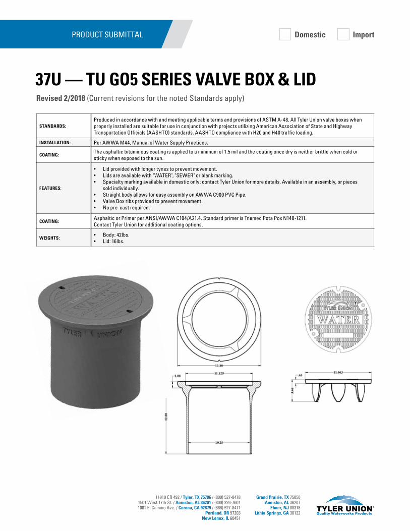
11910 CR 492 / Tyler, TX 75706 / (800) 527-84781501 West 17th St. / Anniston, AL 36201 / (800) 226-76011001 El Camino Ave. / Corona, CA 92879 / (866) 527-8471
Portland, OR 97203New Lenox, IL 60451
Grand Prairie, TX 75050Anniston, AL 36207
Elmer, NJ 08318Lithia Springs, GA 30122
STANDARDS:Produced in accordance with and meeting applicable terms and provisions of ASTM A-48. All Tyler Union valve boxes when properly installed are suitable for use in conjunction with projects utilizing American Association of State and Highway Transportation Officials (AASHTO) standards. AASHTO compliance with H20 and H40 traffic loading.
INSTALLATION: Per AWWA M44, Manual of Water Supply Practices.
COATING:The asphaltic bituminous coating is applied to a minimum of 1.5 mil and the coating once dry is neither brittle when cold or sticky when exposed to the sun.
FEATURES:
• Lid provided with longer tynes to prevent movement. • Lids are available with "WATER", "SEWER" or blank marking. • Specialty marking available in domestic only; contact Tyler Union for more details. Available in an assembly, or pieces
sold individually. • Straight body allows for easy assembly on AWWA C900 PVC Pipe. • Valve Box ribs provided to prevent movement. • No pre-cast required.
COATING:Asphaltic or Primer per ANSI/AWWA C104/A21.4. Standard primer is Tnemec Pota Pox N140-1211. Contact Tyler Union for additional coating options.
WEIGHTS:• Body: 42lbs. • Lid: 16lbs.
PRODUCT SUBMITTAL Domestic Import
37U — TU GO5 SERIES VALVE BOX & LIDRevised 2/2018 (Current revisions for the noted Standards apply)

TylerUnion.com
POCKET ENGINEERAvailable for iOS + Android or online at pe.mcwane.com.
UL®
RE
GISTERED FIR
M
ISO 9001:2015CERTIFIED
10014257
Tyler Union