water, wastewater and reclaimed water technical manual · 1.1.4 all water, wastewater, and...
TRANSCRIPT
(I'\ Hillsborough ~ County Florida
Public Utilities
October 2019
Water, Wastewater andReclaimed Water Technical Manual
HCFLGov.net
Water, Wastewater, and Reclaimed Water Technical Manual ffi Hillsborough ~ County Florida
HILLSBOROUGH COUNTY
WATER, WASTEWATER, AND RECLAIMED WATER TECHNICAL MANUAL
APPROVED
APPROVED: Beth Schinella Date Director, Water Resources Department
OCTOBER 1, 2019 Effective Date (30 days from approval)
October 2019 Page | i
PREFACE
This manual contains current information for designing and submitting potable water, wastewater, and reclaimed water construction plans for proposed projects to be constructed in unincorporated Hillsborough County. This manual is a readily useable reference document written in specific, concise technical language and is a compilation of existing regulations, policy statements, and engineering requirements. The manual was created to ease coordination of projects, and when applicable, facilitate the planning, design and construction of projects in conformance to the County’s standards and requirements.
As material specifications, technical criteria and County polices change to meet new needs and changing technology, it will become necessary to revise and update this manual. The County’s procedure for making revisions which includes issuing technical bulletins, accepting public comments, and requesting design exceptions can be previewed on the County’s website at www.hillsboroughcounty.org. In addition, you can submit comments and suggestions for changes to the manual using the online “Comment on PUD / PW Technical Publications” form located on the County’s website.
October 2019 Page | ii
Water, Wastewater, and Reclaimed Water Technical Manual ffi Hillsborough ~ County Florida
TABLE OF CONTENTS
SECTION 1.0 PROJECT REVIEW AND ACCEPTANCE PROCESS .................... 1-1 1.1 INTRODUCTION ...................................................................................................................... 1-1 1.2 PROJECT REVIEW PROCESS................................................................................................. 1-1 1.3 RIGHT-OF-WAY USE PERMIT SUBMITTALS..................................................................... 1-3 1.4 DEDICATION OF EASEMENTS ............................................................................................. 1-4 1.5 AUTHORITY OF INSPECTORS .............................................................................................. 1-4 1.6 REQUIREMENTS OF ACCEPTANCE .................................................................................... 1-4 1.7 UTILITIES PRODUCT REVIEW COMMITTEE..................................................................... 1-7
SECTION 2.0 PREPARATION OF MASTER PLANS, CONSTRUCTION PLANS, AND RECORD DRAWINGS...................................................... 2-1
2.1 MASTER PLAN......................................................................................................................... 2-1 2.2 CONSTRUCTION PLAN FORMAT......................................................................................... 2-2 2.3 STANDARD ITEMS FOR CONSTRUCTION PLAN REVIEW ............................................. 2-4 2.4 RECORD DRAWING SUBMITTALS FOR PUD .................................................................... 2-8
SECTION 3.0 SPECIFICATIONS FOR DRINKING WATER DISTRIBUTION SYSTEMS DESIGN .................................................................. 3-1
3.1 GENERAL.................................................................................................................................. 3-1 3.2 PLANS PREPARATION ........................................................................................................... 3-1 3.3 PLANS REVIEW ....................................................................................................................... 3-1 3.4 PROJECT ACCEPTANCE......................................................................................................... 3-2 3.5 SYSTEM DESIGN AND FLOW CRITERIA............................................................................ 3-2 3.6 WATER DETAILS..................................................................................................................... 3-5
SECTION 4.0 SPECIFICATIONS FOR WASTEWATER COLLECTION/TRANSMISSION SYSTEMS DESIGN ................. 4-1
4.1 GENERAL.................................................................................................................................. 4-1 4.2 PLANS PREPARATION ........................................................................................................... 4-1 4.3 PLANS REVIEW ....................................................................................................................... 4-1 4.4 PROJECT ACCEPTANCE......................................................................................................... 4-2 4.5 SYSTEM DESIGN AND FLOW CRITERIA............................................................................ 4-2 4.6 WASTEWATER DETAILS ....................................................................................................... 4-4
SECTION 5.0 SPECIFICATIONS FOR RECLAIMED WATER SYSTEMS DESIGN .................................................................................. 5-1
5.1 GENERAL.................................................................................................................................. 5-1 5.2 PLANS PREPARATION ........................................................................................................... 5-1 5.3 PLANS REVIEW ....................................................................................................................... 5-2 5.4 PROJECT ACCEPTANCE......................................................................................................... 5-2 5.5 SYSTEM DESIGN ..................................................................................................................... 5-2 5.6 RECLAIMED WATER DETAILS ............................................................................................ 5-3
October 2019 Page | iii
Water, Wastewater, and Reclaimed Water Technical Manual ffi Hillsborough ~ County Florida
LIST OF TABLES
Table 2-1: Special Circumstances (Design Exceptions) ............................................................................2-4 Table 3-1: Water Flow Peaking Factors ....................................................................................................3-3 Table 4-1: Wastewater Flow Peaking Factors ...........................................................................................4-2
LIST OF FIGURES
Figure 3-1: Water Detail No. TMW-1 .......................................................................................................3-5 Figure 4-1: Wastewater Detail No.TMS-1.................................................................................................4-4 Figure 5-1: Reclaimed Water Detail No. TMR-1 ......................................................................................5-3
APPENDICES
APPENDIX 1: CONSTRUCTION PLAN CHECKLIST
APPENDIX 2: CONSTRUCTION FEATURE INFORMATION AND ASSET DATA SPREADSHEETS
EXHIBIT PIPE ASSETS EXHIBIT PROJECT NODE MAP POTABLE WATER ASSET DATA GRAVITY WASTEWATER ASSET DATA FORCE MAIN WASTEWATER ASSET DATA PUMP STATION WASTEWATER ASSET DATA RECLAIMED WATER ASSET DATA
APPENDIX 3: OVERSIZING PROCESS AND OVERSIZING REIMBURSEMENT PROGRAM
APPENDIX 4: CONNECTION FEASIBILITY FOR WASTEWATER CONNECTIONS
October 2019 Page | iv
Section 1.0 PROJECT REVIEW AND ACCEPTANCE PROCESS
1.1 INTRODUCTION
1.1.1 This technical manual has been prepared as a guide for the design and construction of water, waste-water, and reclaimed water system extensions to Hillsborough County (County) utilities. The specifications, standards, drawings and other information included herein are intended as MINIMUM requirements acceptable for a County facility. While this manual has been developed as a guideline for private enterprise (Developers) the requirements listed herein covering the design, construction, and acceptance criteria for projects is applicable for any project which is to be owned and maintained by Hillsborough County Field Maintenance Services Division (HCFMS) of the Public Utilities Department (PUD).
1.1.2 As a general rule, the County owns and maintains all the water, wastewater, and reclaimed water facilities within the public right-of-way. Therefore, plans for these facilities must be reviewed and approved by the County. In addition, utility facilities that are constructed on private property that are connecting to County facilities are also subject to review, inspection, and approval by the County.
1.1.3 Design plans for new Developer construction projects must be submitted to the Development Services Department (DSD) for review and approval prior to construction. Due of the routine upgrade of the County Technical Specifications and Manuals (every 2 years) it is the Developer/EOR’s responsibility to ensure they are designing to the most current standards in effect at the time of plans submittal. The Service Request (SR) number assigned at submittal determines the year of the applicable standards. Public Utilities has the right to require a submittal to be redesigned when the SR number exceeds the current standards or permitting requirements by more than 2 years at the start of Construction. The Developer is encouraged to communicate regularly with staff in both the DSD and PUD to clarify the specific issues of the project and expedite the review process.
1.1.4 All water, wastewater, and reclaimed water facility plans must be signed and sealed by an Engineer registered in the State of Florida except for those requirements for single family residences that are subject to review by the Architectural Plans Examiners. The DSD reserves the right to establish additional criteria by which to review and approve a given project. The proposed project will be inspected by County personnel during the construction phase. Final acceptance will be processed only after a determination has been made that the construction of the project is in compliance with all applicable regulations of the County and relevant agencies. Before final acceptance, the Developer is responsible for providing the County with signed and sealed RECORD DRAWINGS of the construction and electronic copies of all final design files in accordance with the list of documents specified in paragraphs 1.6.4 and 1.6.5 herein.
1.2 PROJECT REVIEW PROCESS – DEVELOPER INSTALLED PROJECTS
1.2.1 General: This section lists chronologically the steps that the Development Services Department (DSD) follows when reviewing a Developer-installed project. A Developer-installed project is defined as any project in which a private entity designs and constructs water, wastewater and/or reclaimed water facilities which will be owned, operated, and maintained by Hillsborough County
October 2019 Page | 1-1
1.2.2.1
1.2.4.3
PUD. Since each project may have conditions which are project specific, there may be additional requirements not listed in this section.
1.2.2 Application for Service Every Developer involved in the subdivision of real property or the construction of any residential, multi-family, commercial or industrial building within the unincorporated area of Hillsborough County must submit a completed Application for Water, Waste-water, and/or Reclaimed Water Service to the DSD and receive written notification of the Department's determination that:
The County is currently able to provide permanent service to the applicant or will be able to provide it in time to meet the applicant's building schedule; or The County is not able to provide permanent service in time to meet the applicant's building schedule, but future service is programmed in the current six-year Capital Improvement Program (CIP), in which case interim service could be an alternative; or The project is located in the Rural Area and, therefore, the County will not be able to provide permanent water, wastewater, or reclaimed water, in which case permanent service by well, septic system or Community Wastewater Treatment Plant (WWTP) could be alternatives; or The project is located in another municipality’s utility service area and the applicant should submit a service application to that provider, and must submit a copy of their service commitment letter to DSD, prior to Construction Plan approval.
Construction plans may be submitted only after the County’s approval of the submitted Application for Water, Wastewater, and/or Reclaimed Water Service. Actual reservation of plant capacity will be effective upon Construction Plan Approval.
1.2.3 Master Plan: For residential or commercial developments constructed in multiple phases or for single – phase residential projects with more than one pump station, a Master Plan for water, wastewater, and reclaimed water is required. The Master Plan shall be submitted after the County’s approval of the Application for Water, Wastewater and Reclaimed Water Service. The Master Plan must be approved prior to the approval of construction plans.
1.2.4 Construction Plans After obtaining the County's approval of the Service Application (and Master Plan for phased developments), the Developer shall have the construction plans prepared by a Professional Engineer registered in the State of Florida. The signed and sealed plans and specifications are then submitted to the DSD for review. The Developer shall also submit the partially completed Department of Environmental Protection (DEP) water or wastewater construction permit application forms for the DSD to complete, sign, and return. The Developer is responsible for processing any other permits which may be required. The Developer's Engineer is responsible for the coordination of the design with other construction activity in the public rights-of-way and easements, i.e., State, County, and City highway and utility projects. The Engineer shall verify that the project design is compatible with the design of any existing or proposed County CIP project that may impact development. If design conflicts are encountered, the design constraints imposed by the CIP project shall take precedence over the development's design constraints. The DSD Site Engineering Review Section will review the plans and specifications to insure that the facilities proposed for construction are designed in accordance with the criteria in the current "Water, Wastewater, and Reclaimed Water Technical
October 2019 Page |1-2
1.2.4.4
responsibility to ensure that the plans meet the applicable Water, Wastewater, and Reclaimed Water Technical Specifications and Manual in effect at the time of approval. It will be the Engineer/Developer’s responsibility to make any changes/corrections to the design found during construction to be out of compliance with the applicable Water, Wastewater, and Reclaimed Water Technical Specifications and Manual. The approval-for-construction will remain in effect for a period of two years. A two-year extension may be granted if a written request is submitted to the DSD Site Engineering Review Section one month prior to the expiration of the original approval. An extension may be granted if there are no proposed changes to the original approved plans, the plans meet the most current Water, Wastewater, and Reclaimed Water Technical Specifications and satisfy the system hydraulic conditions in effect at that time, and the point of connection remains viable.
Construction The contractor is required to work from a set of plans stamped “approved” by the DSD Site Engineering Review Section. All work must be inspected by County inspection personnel. The contractor shall request an inspection by the PUD Inspection Team a minimum of 48 hours prior to starting construction. The approved set of plans shall be located on the construction site at all times. The Developer, the Engineer of Record (EOR), and the contractor shall comply with all requirements of the Federal, State, and County; and other laws, codes, ordinances, and regulations that in any way affect those engaged or employed in the proposed construction, the materials or equipment used in or upon the site, or the conduct of the work. The Developer, or the Engineer, or the contractor shall obtain all permits and licenses, pay all charges and fees, and provide all notices necessary and incidental to the due and lawful prosecution of the work prior to the start of any construction.
RIGHT-OF-WAY USE PERMIT SUBMITTALS
The Design Engineer shall take the initiative to determine all the agencies with jurisdiction over the project, particularly agencies requiring permits for right-of-way use, such as Hillsborough County, Florida Department of Transportation (FDOT), Tampa Bay Water, Seaboard/CSX Railroad, or any other appropriate authority. These determinations should be made during the
Specifications" and the commitment letter. The hydraulic characteristics of the system will be analyzed by the PUD Utility Planning Team to establish that the proposed system will operate within any specified flow or demand limits. If the plans, specifications, or hydraulics do not conform to the requirements of the current “Water, Wastewater, and Reclaimed Water Technical Specifications,” the Site Engineering Review Section will notify the Engineer and/or Developer of corrections or modifications required. Once DSD determines that the plans are in general conformance with the County's standards, the Developer will be notified in writing that the plans have been approved for construction. Approval does not relieve the Engineer/Developer of
1.2.5
1.3
1.3.1
agency's design and permitting requirements.
1.3.3 The Engineer shall work simultaneously with the involved agency and the DSD in finalizing the plans for submittal.
preliminary design stage.
1.3.2 If the Engineer finds that the project involves a non-county right-of-way, the Engineer shall contact the appropriate local office, discuss the project with their Utility Coordinator and comply with that
October 2019 Page |1-3
1.6.1.1 1.6.1.2
1.6.1.3
1.3.4 County Right-of-Way Use Permits, if required, will be issued upon plan approval by all reviewing agencies. No permit should be issued without a “Letter of Conflict/No Conflict” from PUD Utility Coordination and Conflict Review Team.
1.4 DEDICATION OF EASEMENTS
1.4.1 The Hillsborough County Real Estate Department requires the following items to review and process instruments dedicating property to Hillsborough County:
Current Ownership and Encumbrance Report, title policy or opinion of title from attorney covering the property to be conveyed. Include complete copy of owner's acquiring deed. A marked survey sketch depicting property to be conveyed to Hillsborough County. (All information contained in the legal description must be verifiable by sketch.) Original, executed instrument conveying property to "Hillsborough County, a political subdivision of the State of Florida." If the grantor is an "individual or partnership," use form PUE (Perpetual Utility Easement) 1. If the grantor is a "corporation," use form PUE 2.
1.4.2 Please submit the above items to the DSD for their review and recommendation. Same will be forwarded to the Real Estate Department.
1.4.3 Note: No privately owned structure, including decorative walls, driveways, or fences, shall be constructed in an easement that has been dedicated to the County.
1.4.4 Water, Wastewater, and Reclaimed Water easements outside the right-of-way shall be dedicated for “Hillsborough County Public Utility Department” use, and not specified for “public” use. No private entities shall be allowed to use easements dedicated to the County.
1.5 AUTHORITY OF INSPECTORS PUD Inspection personnel will inspect all construction, all materials, and may inspect preparation, fabrication or manufacture of supplies. The inspector is not authorized to revoke, alter, or waive any requirements of the specifications, but he is authorized to call to the attention of the contractor and/or Engineer any failure of work or materials to conform to the plans or specifications. The inspector will have the authority to reject materials and may suspend the work, especially if public health or safety is involved. If any such rejection or suspension is contested by the Engineer of Record, the issue will be referred to and decided upon by the PUD Utility Design Section Manager. The inspector will not act as foreman, perform other duties for the contractor, or interfere with the management of the work. Any advice which the inspector may give will in no way be construed as binding to the PUD Section Manager or releasing the contractor from carrying out the intent of plans and specifications.
1.6 REQUIREMENTS OF ACCEPTANCE
1.6.1 Final acceptance of a water distribution system, water main extension, reclaimed water distribution system, reclaimed water main extension, and/or wastewater collection/transmission system, including pump stations, and release of the performance bond will be made only after:
All inspections have been made. The improvements are found to be in accordance with the applicable regulations of the County, the DEP, the Hillsborough County Department of Health, and the standards contained herein. For contributed assets (privately developed), the DSD Site Engineering Review Section
October 2019 Page |1-4
1.6.1.4
1.6.4.3
is provided with the required documentation. For County developed projects the County Project Manager is provided with all required documentation.
1.6.2 No Certificate of Occupancy shall be given until all PUD inspections have been approved, and all applicable regulatory requirements have been satisfied. At the County’s discretion a re-inspection of all infrastructure may be required before release of the performance bond if any system has not been put into service within nine months of final inspection.
1.6.3 All requirements of Sections 10.01.05 and 10.01.06 of the Land Development Code are to be met prior to County acceptance of utility and other improvement facilities. The type of acceptance process for off-site utilities (for commercial sites and for subdivisions) constructed in existing road right-of-way depends upon the length of the utility line.
Facilities that are 100 feet or longer in length must be accepted by the Board of County Commissioners (BOCC). Off-site facilities less than 100 feet in length are administratively accepted by the DSD. For utilities less than 100 feet, the Engineer of Record or their representative, will be responsible to witness and sign for any hydrostatic tests performed. Utilities over 100 feet require witness of hydrostatic tests by the PUD Inspector. The Developer will submit a two year letter of warranty for all off-site utilities as part of the acceptance package.
1.6.4 The acceptance of improvement facilities within residential and commercial subdivisions is documented by Dedication in the Final Plat. The Developer has several options in the acceptance process, as summarized below.
The Developer may submit a Plat to the BOCC for acceptance and recording prior to construction completion. In this case, the plat is accepted along with a Subdivider’s Agreement for Construction and a Performance Bond, Letter of Credit, or Cashier’s Check for 110% of the total cost of development. After the project infrastructure is constructed, the Developer submits Record Drawings and final inspection reports, then the project is scheduled to be accepted at a second Board meeting. For this meeting the Developer provides a Subdivider’s Agreement for Warranty and a Two-Year Warranty Bond, Letter of Credit, or check for 10% of the cost of the improvements that the County is accepting for ownership and maintenance. The Board agenda item includes the release of the performance security. The Developer may submit a Plat to the BOCC for acceptance and recording prior to construction completion and the Board can authorize DSD to administratively accept the improvements after construction is completed. In this case, the Developer provides a Subdivider’s Agreement for Construction and Warranty of Required Improvements; a Performance Bond, Letter of Credit, or check for 110% of the total cost of the improvements; and a Warranty Bond, Letter of Credit, or check for 10% of the cost of the improvements. In this case, the performance period, which is usually two years, can vary between six months and two years. The warranty period will be two years, commencing upon acceptance of improvements by DSD. This is the option selected by most subdivision Developers. The submission of a plat may be deferred until construction, Record Drawings, and final inspections are complete. In this case, the plat and improvements are accepted at one Board meeting. For this meeting, the Developer also submits the Subdivider’s Agreement for Warranty of Required Improvements and the two-year Warranty Bond, Letter of Credit, or check for 10% of the cost of the improvements that the County is accepting for ownership and maintenance.
October 2019 Page |1-5
1.6.5 The following is a list of documents that must be submitted to DSD in the acceptance process for subdivision infrastructure improvements. Included in this list are documents related to water, wastewater, reclaimed water, road, and drainage improvements, as applicable. • Letter requesting acceptance • One copy of final plat (Survey) • Five copies of lot grading plans
(Inspections - 1, Main Office Permitting - 1,Satellite Offices Permitting - 3) • One copy of sidewalk plan (Inspections) • Specific cost breakout • One set of test reports • Contractor’s Affidavit • Benchmark Certification • Surveyor’s Certification • EOR’s Certification of Construction Completion • DEP Certification of Completion • Coating Installer/Applicator Certification • Subdivider’s Agreement • Financial Security • Asset Data spreadsheets with Construction feature information (see Appendix 2) • Record Drawings, signed and sealed (showing “as-built” conditions)
- One complete set, roads/ drainage/ water/ wastewater/ reclaimed water (Inspections/File) - Three sets of roads/drainage (Public Works, EPC, SWFWMD) - Two sets of water/wastewater/reclaimed water (PUD Record Archives- 1, Fire Dept.- 1) - One electronic set of Record Drawings (water/ wastewater/ reclaimed water/ roads/
drainage) and one set of project design files (roads, drainage, lot grading, sidewalks, landscaping, irrigation, water, reclaimed water, waste water, etc.) in Adobe PDF format and one DWG geometry file in AutoCAD 2014 or later, saved in 2013 file format. Refer to Section 2.4.1 for submittal format criteria. (PUD Record Archives).
1.6.6 The following is a list of documents that must be submitted to DSD in the acceptance process for off-site utility improvements for commercial developments: • Letter requesting acceptance • Specific cost breakout • One set of test reports • Contractor’s Affidavit • EOR’s Certification of Construction Completion • DEP Certification of Completion • Coating Installer/Applicator Certification • Owner/Developer Agreement • Financial Security • Legal proof that Rights-of-Ways and easements have been dedicated to the County • Asset Data spreadsheets with Construction feature information (see Appendix 2) • Record Drawings signed and sealed (showing “as-built” conditions)
- One complete set of roads/drainage/water/ wastewater/ reclaimed water (Inspections/File) - One set of roads/drainage (Public Works) - Two sets of water/wastewater/reclaimed water (PUD Record Archives.- 1, Fire Dept.- 1) - One electronic set of Record Drawings (water/ wastewater/ reclaimed water/ roads/
drainage) and one set of project design files (roads, drainage, lot grading, sidewalks,
October 2019 Page |1-6
landscaping, irrigation, water, reclaimed water, waste water, etc.) in Adobe PDF format and one DWG geometry file in AutoCAD 2014 or later, saved in 2013 file format. Refer to Section 2.4.1 for submittal format criteria. (PUD Record Archives).
1.6.7 The following is a list of documents that must be submitted to the County PUD Project Manager in the acceptance process for utility improvements: • Letter requesting acceptance • Specific Cost Breakdown • One (1) set of test reports • Contractor’s Affidavit • EOR’s certification of Construction Completion • DEP Certificate of Completion • Coating Installer/Applicator Certification
the applicant in writing regarding the action taken by the Board.
UTILITIES PRODUCT REVIEW COMMITTEE
The Utilities Product Review Committee (PRC) evaluates new and existing products for efficient and economical utilization within the County utility systems.
use through academic research and field evaluation.
as non-participating/non-voting representatives.
• Asset Data spreadsheets with Construction Feature information • Surveyor’s Certification • Record Drawings signed and sealed (showing as built conditions); and one electronic set of
Record drawings and project design files (roads, drainage, grading, sidewalks, landscaping, irrigation, water, reclaimed water, wastewater, etc.) in Adobe PDF format and one complete DWG file in AutoCAD 2014 or later, saved in 2013 file format. Refer to Section 2.4.1 for submittal format criteria. (PUD Record Archives).
1.6.8 Notice of Acceptance: Upon receipt and verification of the above documentation, the DSD will either administratively accept or will request Board of County Commissioners acceptance of the improvement facilities (water, wastewater, reclaimed water) for maintenance and operation. Within three days of action by the Board or through Administrative approval, the DSD shall notify
1.7
1.7.1 The PRC is charged with the
development of a fair and reasonable methodology to systematically evaluate utilities products for
1.7.2 The PRC is comprised of representatives from PUD, Procurement Services, and the Development Services Department. The representatives have technical or management positions and are either design supervisors, maintenance or construction personnel, or have a background in design, maintenance, or construction. Developers, Engineers and contractors may attend the PRC meetings
1.7.3 Appendix B of the Hillsborough County PUD Water, Wastewater, and Reclaimed Water Technical Specifications is a list of water, wastewater, and reclaimed water components, and approved manufacturers and model and/or part numbers. This list will be revised as the PRC adds, changes, or deletes items on this list. To begin the product submittal process follow the procedures as listed on the Hillsborough County PUD website under Technical Specifications, Appendix B.
1.7.4 On a case-by-case basis, the DSD may consider a one-time approval of an alternate material or manufacturer through a design exception submittal prior to final design. The PUD Utility Design Section Manager must review and agree with any such proposed design exception.
October 2019 Page |1-7

1.7.5 A manufacturer or manufacturer’s representative may request a demonstration project for products not currently included in Appendix B. If the PRC agrees, the manufacturer will supply any information requested by the Technical Review Officer (TRO). The PRC may approve the demonstration project with specific conditions and timelines and may require the manufacturer to provide the product at no charge to the County.
October 2019 Page |1-8
2.1.1.1
2.1.1.2 2.1.1.3
2.1.1.4
2.1.1.5
2.1.1.6
2.1.2.2
d) e)
a) b) c)
Section 2.0 PREPARATION OF MASTER PLANS, CONSTRUCTION PLANS, AND
RECORD DRAWINGS
2.1 MASTER PLAN
2.1.1 A “Master Plan” for water, wastewater, and/or reclaimed water is required for all residential or commercial projects to be constructed in multiple phases, or for single – phase residential projects with more than one pump station.
The Master Plans must be approved prior to the approval of construction plans. For large subdivisions the Master Plan may require approval before the point of connection can be issued during the processing of the utility service application. The construction plans must be consistent with the approved Master Plan. For any changes to the development, the Developer must submit a revised and updated Master Plan. All revised Master Plans must be submitted with a letter specifying the proposed revisions to the Master Plan, in addition to the signed and sealed plan drawings submitted in accordance with 2.1.1.5 and 2.1.2. The requirement for submittal of a revised Master Plan may be waived by the Development Services Department (DSD) Site Engineering Review Section, in conjunction with Public Utilities Department (PUD) Utility Planning Section, if the County considers the changes to be minor or not significant. Four signed and sealed plan drawings, along with an electronic version in pdf format, must be submitted to DSD. Master Plan approval does not imply acceptance of easements, construction methods, or other items that may be in conflict with technical standards.
2.1.2 The “Master Plan” will consist of a layout of the major water, wastewater, and/or reclaimed water lines superimposed on a topographic map. The layout plan sheet(s) shall be at a minimum scale of 1 inch = 200 feet and show existing and proposed improvements in sufficient detail to show intent of design. In the event that the number of plan sheets exceeds two (2) sheets at the 1 inch = 200 feet scale, the Master Plan shall be submitted at a scale of 1inch = 500 feet The Master Plan shall be signed and sealed by a Professional Engineer licensed in the State of Florida. The requirements for each specific utility plan include:
General The topographic map shall be of one-foot contours. Developments immediately adjacent to undeveloped tracts shall include a conceptual plan for extension of potable water, wastewater, and/or reclaimed water service to said tracts. “Master Plans” shall have a vicinity map showing the location of the project and the scale used. All plan elevations shall use the 1988 NAVD Vertical Datum. All utilities to be owned by Hillsborough County shall be located within a right of way no smaller than 50 feet in width.
Wastewater Invert and top elevations for manholes. Pipe diameters (both force mains and gravity lines). Total wastewater flow (both average daily flow and peak) to each pump station. A summary of each unit, tract, or phase, including the contribution to each pump station, stating: Type of use (single family residential, master-metered residential,
October 2019 Page |2-1
d) e)
2.1.2.3 a)
b)
c)
d)
e) 2.1.2.4
a)
b)
c)
2.2.1.3
2.2.1.4
2.2.1.5
2.2.1.6
commercial, etc.), Unit Flow Factors, and Peaking Factors. Pump Station locations with top, invert, and bottom elevations Clear delineation of existing versus future units or tracts.
Potable Water Calculations for maximum potable water demand based on full or projected ultimate development or use gross acreage and land use. Maximum water demand will be calculated as peak hour flow plus fire flow per PUD Technical Specification 331001. Consult with the PUD Planning, Records & GIS Section to obtain a “system response curve” (pressure versus flow) representing the County's water distribution network hydraulic response to the requested water demand. Use the network response curve to design a water distribution network. Then, submit the “Master Plan” with a pipe network analysis (e.g., EPANET, KYPIPE, etc.) for flow and pressure distribution for approval. The “Master Plan” shall include connection points and pipe sizes. All available information on hydrant locations and lot platting should be included. Total potable water flow for each unit, tract, or phase stating: Type of use (single family residential, master-metered residential, commercial, etc.), Unit Flow Factors, and Peaking Factors. Clear delineation of existing versus future units or tracts.
Reclaimed Water Calculations for reclaimed water demand. Minimum design standards are outlined in Technical Specification 339001, Part 5 “Design Standard for Reclaimed Water Distribution Systems.” Consult with the PUD Reclaimed Water Planning Team to obtain a “system response curve” representing the County’s distribution network response to the requested water demand. Use the network response curve to design a reclaimed water distribution network. Then, submit the final design with a pipe network hydraulic analysis for flow and pressure distribution for approval. The final design shall include connection points, pipe sizes, meter location(s), and lot platting.
2.2 CONSTRUCTION PLAN FORMAT
2.2.1 General Plans shall be prepared on 24-inch by 36-inch sheets, unless otherwise pre-approved by the County. The cover sheet shall include a vicinity map. An index of all drawings shall be included on the cover sheet or first sheet following. Include an overall utility plan on one sheet and if there are more than three Plan and Profile sheets, include a key map to identify the Plan and Profile sheet numbers. A title block shall be located in the lower right hand corner of each sheet including the cover sheet identifying the Engineer of Record (EOR), firm, telephone number and page content. The title block shall also list the datum used. All pages of blueprint/black line construction plans submitted for review and approval must be signed, sealed, and dated by the Florida Registered Professional Engineer responsible for the project. All submittals must be accompanied by a letter of transmittal to include the DSD assigned Service Request Number, the project Folio Number(s), along with the name, address and telephone number of the project Engineer. If a pressure system is to be constructed, a copy of the manufacturer's pump performance curve overlaid on the system response curve must be included in the submittal.
October 2019 Page |2-2
2.2.1.7 2.2.1.8
All plan elevations shall use the 1988 NAVD Vertical Datum. All construction plans require the EOR to have Level “A” SUE work (locate) performed for all points of connection. Level “A” SUE shall comply with the definition by ASCE 38-02 and adopted by FDOT.
2.2.2 Design Criteria: The design criteria and specifications presented in Sections 3, 4, and 5 herein and within the PUD Water, Wastewater, and Reclaimed Water Technical Specifications shall be used in preparation of design plans and specifications.
2.2.3 Drawings Construction plans with gravity facilities shall show both plan and profile views of the gravity system. Plans with only on-site water, reclaimed water, and wastewater pressure facilities will not require profile views, unless the proposed construction will be within areas of existing infrastructure. The horizontal scale may be one inch = 20 feet down to, but no less than, one inch = 40 feet. The vertical scale shall be one inch = five feet. When proposed construction will be within areas of existing infrastructure, e.g., points of connection to existing infrastructure in the road right-of-way, plan and profile views shall be shown. The horizontal scale shall be one inch = 20 feet and the vertical scale shall be one inch = five feet. All underground utilities, storm drains or other structures which may cross or be located close to the proposed pipelines and structures shall be shown on the drawings in both plan and profile views. Show cross section details of all conflicting crossings and location and elevation of all air release valves.
2.2.4 Utility Easements: Potable and reclaimed water transmission/distribution mains and wastewater collection systems must be constructed within County road rights-of-way. Under special circumstances (design exception), utility lines within easements may be approved, subject to conditions included in Table 2-1.
All perpetual utility easement agreements or easement dedications by Plat shall include the following condition: “No structure shall be placed or constructed, permanently or temporarily, on, in, or over the easement.” Water, wastewater, and reclaimed water easements outside the right-of-way shall be dedicated for “Hillsborough County Public Utilities” use, and not specified for “public” use. No private entities shall be allowed to use easements dedicated to the County.
October 2019 Page |2-3
2.3.1.1 2.3.1.2 2.3.1.3
2.3.1.4 2.3.1.5
2.3.1.6 2.3.1.7 2.3.1.8 2.3 .1.9
Table 2-1: Special Circumstances (Design Exceptions)
Special Circumstances
Easement Over Lot
Lines
Gravity Wastewater Lines
• Easement width of 20 feet (minimum) • Line installed in the center of the easement • Pipe material shall be PVC for pipe sizes 12” and
less • No Lateral connections allowed
Pressure Lines (Potable/Reclaimed Mains,
Force Mains)
• Easement width of 20 feet (minimum) • Line installed in the center of the easement • Line installed within a steel sleeve • Sleeve to extend minimum of 15 feet beyond front
plane of adjacent houses and 20 feet minimum beyond the rear plane of adjacent houses
• Top of sleeve to be a minimum of three feet (potable/reclaimed) or four (force main) feet below grade
• Install isolation valves in the right-of-way and near the rear of the lots
Easement in Open Area
Gravity Wastewater Lines
• Easement width of 25 feet (minimum) for lines up to 15 feet deep
• Easement width of 30 feet (minimum) for lines greater than 15 feet deep
• Line installed in the center of the easement • Pipe material shall be PVC for pipe sizes 12” and
less • No lateral connections allowed
Pressure Lines (Potable/Reclaimed Mains,
Force Mains)
• Easement width of 20 feet (minimum) • Line installed in the center of the easement
2.3 STANDARD ITEMS FOR CONSTRUCTION PLAN REVIEW
2.3.1 All Construction Plans Plans on 24-inch by 36-inch paper. Proper scale is used and noted on each view. Plans must reflect the approved point of connection (P.O.C.) as specified in the "Service Application Conditional Approval Letter." North arrow, abbreviations, notes, etc. Signed, sealed and dated by the Engineer of Record registered in the State of Florida (all sheets). Width and center line of each right-of-way indicated. Width of pavement and distance to property line shown for all streets. Street names or identifiers indicated (correct location on plan). Subdivision name, lot, and block numbers.
October 2019 Page |2-4
2.3.1.10
2.3.1.11 2.3.1.12
2.3.1.13
2.3.1.14
2.3.1.15 2.3.1.16
2.3.1.17
2.3.1.18
2.3.1.19
2.3.2.1
2.3.2.2
2.3.2.7
All existing County-regulated utilities proximate to the design shall be shown on the plan view in their reported location with dimensioning. Maintain a minimum of 18 inches vertical clearance for all utility crossings. Size, type, material, and length of pipes shown for all water, reclaimed water, and wastewater lines both on-site and off-site. Whenever the water, reclaimed water, or wastewater line crosses existing pavement, specify the crossing method, i.e., jack and bore or open-cut. Specify the invert of all intersecting utilities on the plan or profile views with the accompanying SUE information.
The joint restraint detail shall conform to County
a tee, four valves on a cross), loop ends, fire hydrant stubs and other locations, as required by Hillsborough County PUD to facilitate operation of the distribution system. Valves shall be placed so that the maximum allowable length of water main required to shut down for repair work shall not be more than 500 feet in commercial, industrial, multi-family and residential districts; and 1,000 feet in rural areas.
line that is to be continued. Specification 331001.
Minimum line clearance from property line is five feet. Minimum cover is 36 inches over water and reclaimed water pipelines, and 48 inches over force main pipelines. Permanent structures shall not be constructed in easements or right-of ways containing water, reclaimed water or wastewater utilities. An aesthetic plan to address above ground water meter assemblies and any other above ground facilities shall be submitted explaining how visual impact is to be minimized. A minimum five-foot “landscape free” buffer shall be maintained around a meter slab. No mulch or landscape shall be installed within this buffer zone. Datum information shall be marked on each sheet of the utility plans.
2.3.2 Plans with Water Mains Joint restraint length shall be specified at all water main bends, valves, fittings, fire hydrants, and tapping sleeves. The joint restraint information shall be included on the plan and profile drawings. specifications. Valves with roadway boxes shall be provided for all branch connections (three valves on
If construction is to be phased, a valve followed by one full length of pipe must be installed at the end of each
Valves shall meet the requirements of PUD Technical
Air release valves, or fire hydrants, shall be specified water main high points where the profile is such that air pockets or entrapment could occur resulting in flow blockage. Manual air release valves are preferred, over automatic ARV’s. Fire hydrant spacing in accordance with PUD Technical Specification 331001. The location of sleeves for use in connection with far side water service installations. Water distribution mains within residential subdivisions shall be PVC, or Ductile Iron Pipe (DIP), and shall comply with the requirements of PUD Technical Specification 331001. All other water mains shall be DIP. Note size and type of material. A note indicating that PVC water mains shall have suitable locator/tracer wire affixed to the pipe.
October 2019 Page |2-5
2.3.3 .1
2.3.3.2
2.3.3.3
2.3.3.4 2.3 .3.5 2.3.3.6
2.3.3.7
2.3.4.1
2.3.4.2
2.3.4.3
2.3.4.4
2.3.4.5
2.3.5.3
2.3.5.4
2.3.3 Plans with Wastewater Gravity Mains For gravity mains, the size, type of pipe, slope, and distance between manholes shall be stated on the profile view. Invert elevations and directions shall be specified for each pipe entering or exiting a manhole. Rim elevation must also be specified. Identify the lowest point (rim elevation) in the gravity system. All manhole stubs and connections shall be shown on both the plan and profile view. All stubs shall include plugs.
2.3.4
2.3.5
Manhole and manhole connection details shall be shown. Drop manhole and detail is required for drops two feet or more. Gravity lines shall be eight-inch PVC minimum within right-of-way, six-inch minimum for double service laterals, and four-inch minimum for single service laterals. Manholes shall include water-tight manhole cover inserts.
Plans with Wastewater Force Mains Joint restraint length shall be specified at all force main bends, valves, fittings, and tapping sleeves. The joint restraint information shall be included on the plan and profile drawings. The joint restraint detail shall conform to County specifications. Valves with roadway boxes shall be provided for all branch connections (three valves on a tee, four valves on a cross), and other locations as required by the Hillsborough County PUD to facilitate the operation of the distribution system. In-line valves shall be provided at intervals not to exceed 1,000 feet. Valves shall meet the requirements of PUD Technical Specification 333002. Air release valves shall be specified where the force main profile is such that air pockets or entrapment could occur resulting in flow blockage. A note indicating that all PVC force mains shall have a locator/ tracer wire affixed to the pipe. Pipe used in force mains shall comply with the requirements of PUD Technical Specification 333002.
Plans with Reclaimed Water Mains Joint restraint length shall be specified at all reclaimed water main bends, valves, fittings, and tapping sleeves. The joint restraint information shall be included on the plan and profile drawings. The joint restraint detail shall conform to County specifications. Valves with roadway boxes shall be provided for all branch connections (three valves on a tee, four valves on a cross), and other locations as required by Hillsborough County PUD to facilitate operation of the distribution system. Valves shall be placed so that the maximum allowable length of reclaimed water main required to shut down for repair work shall not be more than 1,000 feet in commercial, industrial, multi-family, and residential districts; and 2,000 feet on transmission systems. If construction is to be phased, a valve followed by one full length of pipe shall be installed at the end of each line that is to be extended. Valves shall meet the requirements of PUD Technical Specification 339001. Air release valves (manual preferred) shall be specified where the water main profile is such that air pockets or entrapment could occur resulting in flow blockage. The location of sleeves for use in connection with far side water service installations.
October 2019 Page |2-6
2.3.5.5
2.3.5.6
2.3.6.1
2.3.6.2
2.3.6.3 2.3.6.4
2.3.7.1 2.3.7.2 2.3.7.3
2.3.7.4 2.3.7.5
2.3.8.1
2.3.8.2
.. . 3 2. 8. 2.3 . . 2.3.8.6 2.3 .8.7 2.3.8.8 2.3.8.9 2.3.8.10 2.3.8.11
2.3.8.1 2
Reclaimed water distribution mains within residential subdivisions shall be PVC, or Ductile Iron Pipe (DIP). All other water mains shall be DIP. Note size and type of material. A note indicating that PVC reclaimed water mains shall have a locator/tracer wire affixed to the pipe.
2.3.6 Jack and Bore Crossings Jacked crossings shall show the casing pipe on both the plan and profile view. County standard jacking detail must be included. Jack & Bore details can be found in, Specification 331002 for potable water mains; Specification 333006 for wastewater mains; and Specification 339002 for reclaimed water mains. Refer to Specification 330524 for installation requirements. A cross sectional detail of the jacking shall be included with all accompanying SUE information. All utility crossings require a Level “A” SUE locate. Casing pipe diameter must be specified on the detail and profile views. Class and thickness of casing pipe shall be specified.
2.3.7 Wastewater Pump Stations (privately owned) Location of pump station on private property. Design capacity (average daily/peak flows) and system response/curve calculations. Pump identification, including all nameplate data. Pump curve for selected pump with design point noted. Wet well operating elevations, inverts, and slab elevations. Identification of fittings and valves on private property.
2.3.8 Wastewater Pump Stations (to be County owned and maintained) Size of site to be dedicated to County. The service driveway shall be a minimum of 28 feet from edge of road pavement to front of pump station fence/gate, unless otherwise approved. Setback requirements for a Master Pump Station (serves 3,000 ERCs or more) are 20 feet to residential lot line and 50 feet to surrounding residential structures or building envelopes. Setback requirements for a Neighborhood Pump Station (serves less than 3,000 ERCs.) are 20 feet to the rear or side lot line and 30 feet to surrounding residential structures or building envelopes. All utilities required for maintenance and operation of the pump station. Valve and piping identification. Backflow prevention device. By-pass capabilities. Pump identification, including all nameplate data. Design capacity (average daily/peak flows) and system response/curve calculations. Wet well design criteria and pump control level settings. Pump curve for selected pump with design point noted. Information in Sections 2.3.8.7 - 2.3.8.10, above, shall be included on a pump station calculations detail sheet. Electrical Load Calculation, short circuit analysis, arc-flash classification for each control panel, and Breaker Coordination Study included on electrical sheet.
2.3.9 Wastewater Pump Stations Hydraulic Requirements: Prior to actual design of any pumping station, the Developer's Engineer must contact the Site Engineering Review Section of the Development Services Department and the Utility Planning Section of PUD. Proper coordination between the
October 2019 Page |2-7
Developer's Engineer and these Sections will assure the proposed pumping station will meet the hydraulic requirements of the County wastewater system.
2.3.10 Plan Submission Check List: Appendix 1 is a check list which the Engineer may use, if desired, as a final check on construction plans prior to plan submission to the County.
2.4 RECORD DRAWING SUBMITTALS FOR PUD
2.4.1 Following completion of construction and testing, the Engineer of Record (licensed in the State of Florida) shall submit, to the DSD Site Engineering Review Section, or the HC Project Manager (for Capital Improvement Projects), the following:
CD containing the following "Record” drawings files: AutoCAD files: • Development Projects (Contributed Assets): One (1) AutoCAD 2014 or later
DWG file saved in 2013 file format having no XREF dependencies and containing a consolidated, pre-construction base map geo-referenced to the West Florida State Plane coordinate system and visibly include at least one (1) County benchmark published in LABINS. Said base map shall include the site topography, roadway geometry, all existing utility geometry (water, wastewater, reclaimed water, storm water, and other buried utilities if known), all newly installed utility geometry (water, wastewater, reclaimed water, and storm water), and all newly installed utility features (valves, fittings, manholes, etc.). All geometry and utility features shall be easily discernable (line weight and type) on separate layers with appropriate labeling. No cross sections, profiles, construction notes, tabs, dimensions, or details need to be included.
• Capital Improvement Projects: One (1) AutoCAD 2014 or later DWG file saved in 2013 file format with all associated XREFs, blocks, sheets, survey drawings, details, profiles, DWF underlays, raster images, data point files, point file format descriptors, TIN and FLT files. Also, one (1) consolidated drawing file in DWG format meeting all the requirements of the Contributed Assets submittal delineated above.
PDF files: • All projects: One (1) PDF file containing a complete set of Record Drawings for
the Project. The PDF file shall include the entire project plan set, from cover sheet through the final details. It shall be comprehensive in nature and include all water, wastewater, and reclaimed water utility design sheets, all plan/profile sheets, all roadway design sheets, all storm water utility and drainage design sheets, all cross sections, all construction details, and any landscaping plans associated with the project (saved at 24-inch by 36-inch, 300 DPI with bar scale).
• Capital Improvement Projects: One (1) color PDF of the Contractor’s red lined markups (As-built plan set).
In addition, three sets of rolled 24-inch by 36-inch blue or black line prints, all pages signed and dated in ink and sealed by the Engineer of Record. If BOCC acceptance is not required, the number of blue/black line print sets can be reduced to two.
2.4.2 All drawing revisions shall be consistent in style, color, line weight, font, symbol, and layer with the original construction documents. No additional colors, fonts, line weights, or block symbols shall be accepted.
2.4.3 All file revisions must be performed on a computer using AutoCAD 2014 or later. No conversions
October 2019 Page |2-8
2.4.4.1
2.4.4.2
2.4.5.1
2.4.5.2
a)
b)
c) d) e)
f) g)
h) i)
a)
from Microstation or other CAD based programs will be accepted.
2.4.4 Record drawings must reflect all changes to the approved construction plans. The completed Record Drawings shall have the look and appearance of the original construction plans, meeting the standards set forth in section 2.4.2 above. When Record drawings have numerous changes, or are so “congested” that legibility is an issue, the County will require the Engineer of Record to supply additional sheets showing the detailed changes to the original plans. The Record Drawings shall also include the following information:
All Water/Wastewater/Reclaimed Water Record Drawings Offsets from edge of pavement and right-of-way to pipe lines shall be shown at not greater than 200 feet intervals. Location of the ends of casing pipe, concrete encasement, and sheeting by X-Y-Z coordinate. Include size (diameter), length, material type and wall thickness of casing. Grade elevations. Datum information Record changes in alignment or elevation of other utilities due to construction. Record all found utilities not shown on approved construction plans. Installed pipe diameter, material type, and AWWA/ASTM/ANSI classification. If abandonment of existing facilities is approved by the County, provide size, type, depth, location, and limits (XYZ coordinates) of any abandoned pipe. Also include the method of abandonment (i.e., grout filled, etc.). Cross-sectional details shall be provided where utilities cross. Record Drawings shall contain a clear statement if the project name has changed.
Water, Wastewater, and Reclaimed Water Pressure Pipe Drawings X-Y-Z coordinates taken at the top of pipe/appurtenance and at finished grade for all fittings, bends, reducers, sleeves, plugs, caps, tees, crosses, taps, restrained joints, valves, blow-offs, hydrants, high and low points, etc. Provide installed top of pipe (XYZ coordinates) and finished grade elevations at a minimum of 200 feet intervals for all pressure mains and at all high points for air release valves. X-Y-Z coordinates for all service connections when they are not on property lines.
Gravity Line Drawings On the plan view, show X-Y-Z coordinates at center of wastewater manhole cover. Annotate the distance between manholes, finished rim elevations, entrance and exit pipe invert elevations, invert directions at each manhole, and pipe slopes on plan and profile sheets. Provide X-Y of all lateral cleanouts and the depth of cover at the property line if it is less than or greater than the standard depth (three feet – four feet). Provide size, length, invert elevation and surface grade of stub outs for future connections.
2.4.5 Other Certification: When certification of "Record" Drawings is performed by an Engineer other than the Design Engineer, the following requirements shall apply:
The certification shall be completed by a Registered Professional Engineer (PE) licensed in the State of Florida. Any deviations from the original design which were made shall be coordinated with the Design Engineer to insure that the integrity of the original design was not compromised. The Record Drawing shall meet all the requirements of section 2.4.4 above, with the
October 2019 Page |2-9
2.4.5.3
exception that any items revised by the certifying Engineer shall be highlighted on the drawing, using a small numbered triangle and annotated in the revision block. Revisions shown on Record Drawings shall be in CAD or drafted to the same quality as the original drawings, not hand drawn. All revisions to computer generated drawings shall be made in AutoCAD 2014 or later saved in 2013 file format using the same symbols, style, colors, line weights and fonts as used in the original drawings. All completed Record Drawings shall have the look and appearance of the original drawings. A statement by the certifying Engineer, responsible for making the revisions, shall be placed on each sheet, which states that they made the revisions designated by the numbered triangles and is responsible for the revision.
Each sheet shall contain the certifying Engineer's engineering company logo with their Certificate of Authorization, name, address and telephone number. Each sheet shall contain a statement that the certifying Engineer, or someone under their direct supervision, observed the construction, prepared the Record Drawing, and found that the construction was performed in substantial compliance with the intent of the design drawings. Statements by the certifying Engineer disclaiming responsibility for accuracy of Record Drawings are NOT allowed. The certifying Engineer shall sign in ink, date, and seal each record drawing sheet. Drawings and electronic file submittals shall comply with the requirements in Section 2.4.1
2.4.6 Construction Feature Information/Asset Data Templates: Information on the as-built features (potable water, wastewater, and reclaimed water) shall be submitted per Appendix 2. The information shall be submitted on a CD at the time of Record Drawing submittal. Each feature on the spreadsheet shall be given a unique ID that shall correspond with its designation on the Record Drawings.
October 2019 Page |2-10
Section 3.0 SPECIFICATIONS FOR DRINKING WATER
DISTRIBUTION SYSTEMS DESIGN
3.1 GENERAL
3.1.1 The following specifications cover the general design, review of plans and specifications, and
All water distribution systems, water main extensions, and all appurtenant items shall be designed in accordance with the applicable regulations of Hillsborough County, the Hillsborough County Department of Health, the Florida Department of Environmental Protection and the standards
including the water meter.
in Appendix 3, shall be followed.
acceptance of drinking (potable) water distribution systems, water main extensions, and all appurtenant items which are to be constructed by private enterprise and are to be owned and maintained by Hillsborough County.
3.1.2 The Public Utilities Department (PUD) Technical Specification 331001 “Water Mains & Appurtenances” shall provide additional clarification regarding design details, materials of construction, installation and acceptance requirements. If further clarification is needed, contact the Site Engineering Review Section of the Development Services Department (DSD) or the Utility Design Section of the PUD.
3.1.3 All improvements and modifications made to the Hillsborough County water system shall be done in accordance with plans approved by the Site Engineering Review Section of the DSD. Material, workmanship, and installation shall comply with PUD Technical Specification 331001.
3.1.4 All pipeline and appurtenance materials in contact with potable water must be NSF-61 certified.
3.2 PLANS PREPARATION
3.2.1
established herein.
3.2.2 Hillsborough County PUD shall own and maintain all portions of the water system up to and
When a distribution main will serve existing or future developments beyond the borders of the proposed site, the County may request oversizing. If the County determines that a line needs to be “Oversized”, the procedures for sizing and reimbursement, as outlined
The distribution system or any portion thereof, which is to become the property and sole responsibility of Hillsborough County PUD, shall be designed and constructed within a public right-of-way or easement which may be used for said purpose. The primary feed for the distribution system shall be routed within County road right-of-way. A secondary feed may be routed within a utility easement dedicated to the County (design exception).
3.2.3 The water distribution system or water main extension shall be designed and constructed in accordance with the requirements specified in PUD Technical Specification 331001.
3.3 PLANS REVIEW
3.3.1 For subdivision development, the Developer shall comply with the procedures and requirements set forth in Article VI, Part 6.02.00 of the County's Land Development Code. This includes the
October 2019 Page |3-1
3.5.4.2
3.5.4.3
requirement for submittal, review, and approval of a preliminary plat of the proposed project and potable water master plan. The placement of appurtenances in Hillsborough County right-of-way shall be as required in the Utility Accommodation Guide and Rights of Way Use Procedures Manual.
3.3.2 For site development, the Developer shall comply with the procedures and requirements set forth in Article VI, Part 6.03.00 of the County's Land Development Code. The Developer shall submit plans and associated documentation to the Site Engineering Review Section of the Development Services Department for review. This department will either accept or reject the plans with notations for corrections required. All plans shall comply with the requirements of Section 2.0 herein
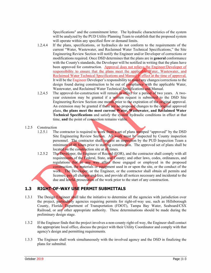
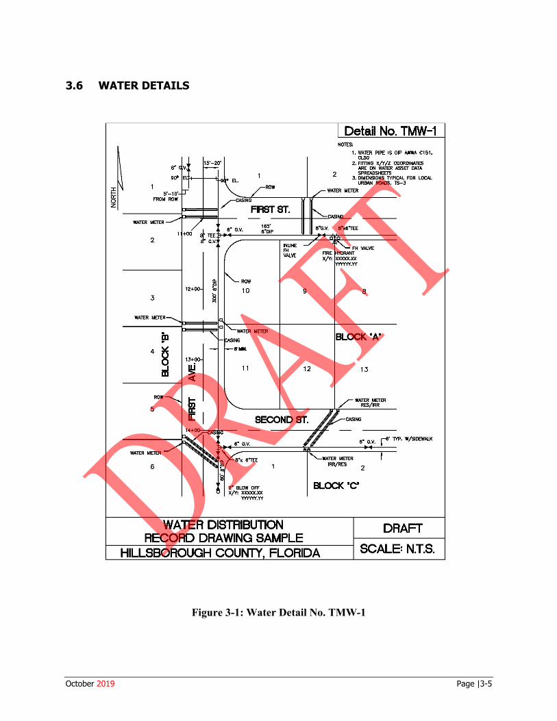
3.4 PROJECT ACCEPTANCE Following completion of construction and testing, the Developer's Engineer of Record shall submit certified “Record” drawings and the Asset Data spreadsheet with the “as-built” information shown on the original design as outlined in Section 1.6 and Section 2.4. Information required on a “Record” drawing of a typical water collection system is shown in Figure 3-1
3.5 SYSTEM DESIGN AND FLOW CRITERIA
3.5.1 The provisions of this Section set forth the general requirements for design of potable water distribution systems and facilities, and provide criteria for determining flow demands. The Engineer shall comply with all the requirements of the Hillsborough County Health Department in addition to the criteria contained herein.
3.5.2 Line Sizing Criteria: The pipe sizing design criteria for water distribution systems shall as a minimum provide for at least 100% of the combined peak hour, maximum day demand rate, plus fire flow. The allowable minimum service pressure under said design condition shall not be less than 20 psi, or 35 psi in a transmission line. Design flows and method of computation shall be submitted to DSD for review by the PUD Utility Planning Team at the time of the preliminary plat or site plan submittal, or at the time of the Master Plan submittal. If the County determines that a line needs to be “Oversized”, the procedures for sizing and reimbursement, as outlined in Appendix 3, shall be followed.
3.5.3 Minimum Line Size: The minimum pipe size for distribution mains shall be four inches, with the exception that the minimum size for distribution mains serving fire hydrants and fire hydrant branches shall be a minimum of six inches in diameter.
3.5.4 Line Routing The primary feed for the water distribution system for a residential or commercial subdivision shall be routed within County road right-of-way. A secondary feed may be routed within a water, wastewater, or reclaimed water utility easement that is dedicated to the County (design exception), only if there is no road right-of-way available. Multiple points of connection may be required in order to minimize service outage in emergencies, repairs, etc., and to improve fire protection and water quality. The County requires a project’s off-site infrastructure to be extended beyond the development point(s) of connection in the right-of-way to the extent of the development's property. As a minimum, at the entrance to the project, the off-site main extension shall be extended within the right-of-way with a valve and one length of pipe with a cap. Refer to the Hillsborough County Public Works Transportation Technical Manual
October 2019 Page |3-2
3.5.6.1
Drawings, latest edition, for the Recommended Utility Locations, TS-1
3.5.5 Depth of Cover: • Cover as measured from finished grade to top of the pipeline shall be a minimum of 36 inches
for pipe diameters up to and including 12 inches. • Depth of cover for pipes 16 inches or greater in diameter shall be a minimum of 48 inches. • When automatic air release valves are required for pipe diameters up to and including 12
inches, the depth of cover of the entire line must be increased to a minimum of 48 inches (to maintain the valve vault flush with the existing or proposed grade).
• For pipe in FDOT right-of-way, or on County arterial roads, the minimum depth of cover shall be 48 inches.
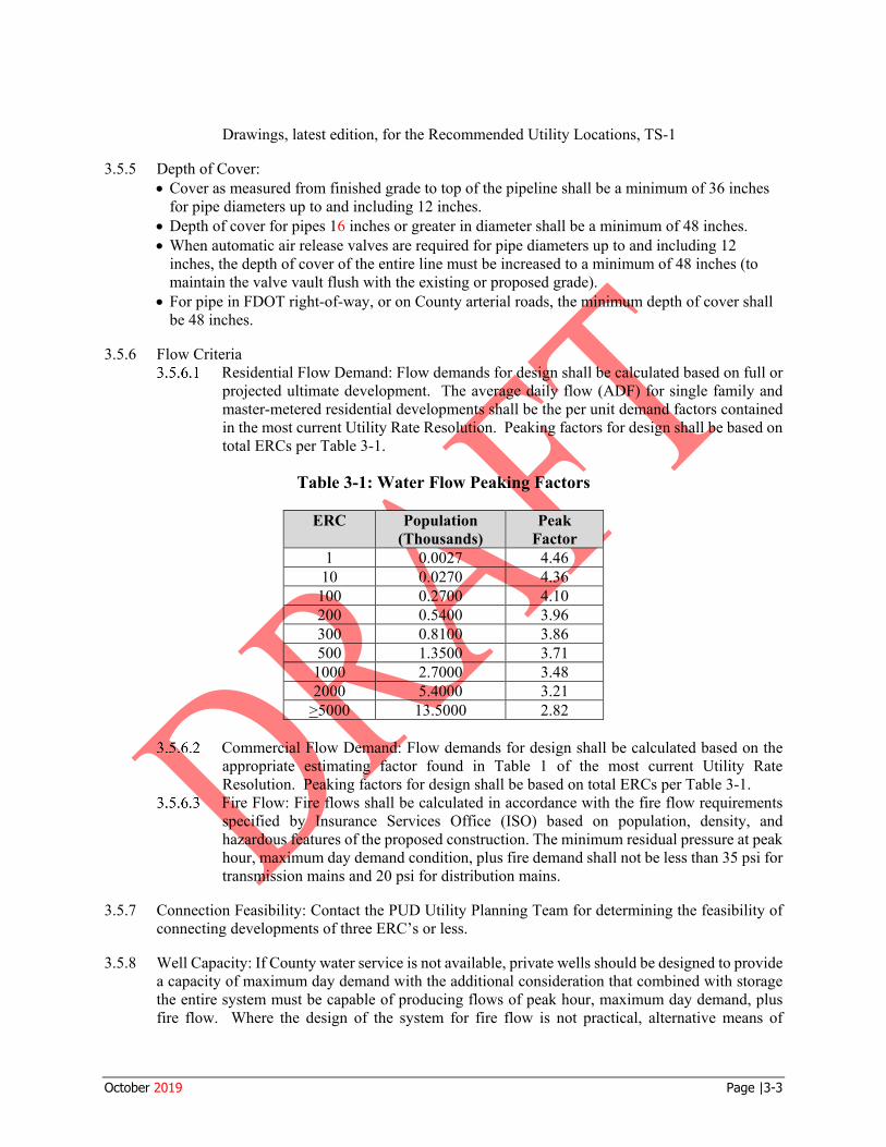
3.5.6 Flow Criteria Residential Flow Demand: Flow demands for design shall be calculated based on full or projected ultimate development. The average daily flow (ADF) for single family and master-metered residential developments shall be the per unit demand factors contained in the most current Utility Rate Resolution. Peaking factors for design shall be based on total ERCs per Table 3-1.
Table 3-1: Water Flow Peaking Factors
ERC Population (Thousands)
Peak Factor
1 0.0027 4.46 10 0.0270 4.36
100 0.2700 4.10 200 0.5400 3.96 300 0.8100 3.86 500 1.3500 3.71
1000 2.7000 3.48 2000 5.4000 3.21
>5000 13.5000 2.82
Commercial Flow Demand: Flow demands for design shall be calculated based on the appropriate estimating factor found in Table 1 of the most current Utility Rate Resolution. Peaking factors for design shall be based on total ERCs per Table 3-1. Fire Flow: Fire flows shall be calculated in accordance with the fire flow requirements specified by Insurance Services Office (ISO) based on population, density, and hazardous features of the proposed construction. The minimum residual pressure at peak hour, maximum day demand condition, plus fire demand shall not be less than 35 psi for transmission mains and 20 psi for distribution mains.
3.5.7 Connection Feasibility: Contact the PUD Utility Planning Team for determining the feasibility of connecting developments of three ERC’s or less.
3.5.8 Well Capacity: If County water service is not available, private wells should be designed to provide a capacity of maximum day demand with the additional consideration that combined with storage the entire system must be capable of producing flows of peak hour, maximum day demand, plus fire flow. Where the design of the system for fire flow is not practical, alternative means of
October 2019 Page |3-3
3.5.9.1
3.5.9.2
3.5.9.3
3.5 .9.4
3.5.10.1
providing fire flow such as dry hydrants may be used subject to approval of the DSD Site Engineering Review Section and the County Fire Marshal’s Office.
3.5.9 Fire Hydrant Spacing, Location, and Flow Manufacturing and Industrial Areas: Fire hydrants shall be placed every 300 feet along the right-of-way with a maximum of 150 feet to the last lot. The minimum required fire flow shall be 1000 gpm, provided by either: 1) each hydrant individually, or 2) multiple hydrants flowing simultaneously. The required fire flow shall be determined by the County Fire Marshal’s Office as part of the preliminary plan review process. Hydraulic capacity of the system may be able to provide fire flow above the 1000 gpm minimum, but any required fire flow not provided by the system must be provided onsite. Commercial and Apartment Areas: Fire hydrants shall be placed every 500 feet along the right-of-way with a maximum of 250 feet to the last lot. The minimum required fire flow shall be 1000 gpm, provided by either: 1) each hydrant individually, or 2) multiple hydrants flowing simultaneously. The required fire flow shall be determined by the County Fire Marshall’s Office as part of the preliminary plan review process. Hydraulic capacity of the system may be able to provide fire flow above the 1000 gpm minimum, but any required fire flow not provided by the system must be provided onsite. Residential Areas: Fire hydrants shall be placed a maximum of 500 feet apart along the right-of-way with a maximum of 500 feet to the last lot. The minimum flow from each hydrant shall be 750 gpm. Other Areas: Fire hydrants shall be placed a maximum of 1,000 feet apart, along the right-of-way of rural roads or other areas as approved by the County on a case-by-case basis.
3.5.10 Temporary Water Service for Construction The provisions set forth herein shall be applicable to all construction projects. The developer shall be responsible to submit a temporary water plan (Plan). The Plan shall describe how water will be provided and metered for construction needs and, if applicable, fire demand. It shall include the maximum peak hour flow which will be required prior to acceptance for occupancy. The Plan shall be submitted to the Development Services Department along with the required construction plans. Water service for construction shall be supplied using a temporary construction assembly as described in PUD Technical Specification 331001. Private sources, such as wells, may also be acceptable to the County.
October 2019 Page |3-4
Ii: 0 z
15'-20'
ROW
2
ROW
12+00 10 3
WATER METER
ED
4 ~ 13+00
m ~ 11
ROW
11 5
WATER METER
6
~ 2" BLOW OFF X/Y: XXXXX.XX
Y'fYYYY.YY
WATER DISTRIBUTION
INUNE FH VALVE
9
12
RECORD DRAWING SAMPLE
2
Detail No. TMW-1 NOTES:
1. WATER PPE IS DIP AWWA C1~1. Cl..50
2. FITTING X/Y /Z COORDINATES ARE ON WAlER ASSET DATA SPREADSt£EIS
3. DIMENSIONS TYPICAL FOR LOCAL URBAN ROADS, TS-3
8
BLOCK "A"
13
CASING
6' G.V. ' TYP. W/SIDEWALK
2
BLOCK 'C'
DRAFT
HILLSBOROUGH COUNTY FLORIDA SCALE= N.T.S.
3.6 WATER DETAILS
Figure 3-1: Water Detail No. TMW-1
October 2019 Page |3-5
Section 4.0
acceptance of wastewater collection systems, wastewater pumping stations, wastewater transmission force mains, wastewater line extensions and all appurtenant items which are to be owned and maintained by Hillsborough County.
The Public Utilities Department (PUD) Technical Specifications 333001 “Gravity Wastewater Sewers and Appurtenances”, 333002 “Wastewater Force Mains and Appurtenances”, and 333003 “Wastewater Pumping Stations”, shall provide additional clarification regarding design details, materials of construction, installation, and acceptance requirements. If further clarification is needed, contact the Site Engineering Review Section of the Development Services Department (DSD) or the Utility Design Section of PUD.
All improvements and modifications made to the Hillsborough County wastewater system shall be done in accordance with plans approved by the Site Engineering Review Section of DSD. Material and workmanship shall comply with PUD Technical Specifications 333001, 333002, and 333003.
PLANS PREPARATION
All sanitary wastewater collection systems, wastewater pumping stations, wastewater transmission force mains, wastewater line extensions, and all appurtenant items shall be designed in accordance with the applicable regulations of Hillsborough County, Hillsborough County Department of Health, the Florida Department of Environmental Protection and the standard established herein.
When a wastewater main will serve existing or future developments beyond the borders of the proposed site, the County may request oversizing. If the County determines that a line needs to be “Oversized”, the procedures for sizing and reimbursement, as outlined in Appendix 3, shall be followed.
The wastewater collection system or wastewater transmission system or any portion thereof, which is to become the property and sole responsibility of Hillsborough County PUD, shall be designed and constructed within a public right-of-way or easement (design exception) which may be used for said purpose. Refer to the Hillsborough County Public Works Transportation Technical Manual Drawings, latest edition, for Recommended Utility Locations, TS-1.
PLANS REVIEW
SPECIFICATIONS FOR WASTEWATER COLLECTION/TRANSMISSION SYSTEMS DESIGN
4.1 GENERAL
4.1.1 The following specifications cover the general design, review of plans and specifications, and
4.1.2
4.1.3
4.2
4.2.1
4.2.2
4.2.3
4.3
4.3.1 For subdivision development, the Developer shall comply with the procedures and requirements set forth in Article VI, Part 6.02.00 of the County's Land Development Code. For site developments, the Developer shall comply with the procedures and requirements set forth in Article VI, Part 6.03.00 of the County's Land Development Code. The placement of appurtenances in Hillsborough County right-of-way shall be as required in the Utility Accommodation Guide and Rights of Way Use Procedures Manual.
October 2019 Page |4-1
4.3.2 The Developer or authorized representative shall submit plans and associated documentation in accordance with the procedures and requirements set forth in Article VI, Part 6.03.00 of the County's Land Development Code. The Site Engineering Review Section will either accept or reject the plans with notations for corrections required. All plans shall comply with the requirements of Section 2.0 of the Hillsborough County PUD Technical Manual.
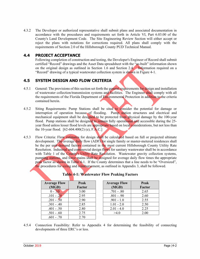
4.4 PROJECT ACCEPTANCE Following completion of construction and testing, the Developer's Engineer of Record shall submit certified “Record” drawings and the Asset Data spreadsheet with the “as-built” information shown on the original design as outlined in Section 1.6 and Section 2.4. Information required on a “Record” drawing of a typical wastewater collection system is shown in Figure 4-1.
4.5 SYSTEM DESIGN AND FLOW CRITERIA
4.5.1 General: The provisions of this section set forth the general requirements for design and installation of wastewater collection/transmission systems and facilities. The Engineer shall comply with all the requirements of the Florida Department of Environmental Protection in addition to the criteria contained herein.
4.5.2 Siting Requirements: Pump Stations shall be sited to consider the potential for damage or interruption of operation because of flooding. Pump station structures and electrical and mechanical equipment shall be designed to be protected from physical damage by the 100-year flood. Pump stations shall be designed to remain fully operational and accessible during the 25-year flood unless lesser flood levels are appropriate based on local considerations, but not less than the 10-year flood. [62-604.400(2) (e), F.A.C.]
4.5.3 Flow Criteria: Flow estimates for design shall be calculated based on full or projected ultimate development. The average daily flow (ADF) for single family or master-metered residences shall be the per unit demand factors contained in the most current Hillsborough County Utility Rate Resolution. Industrial and commercial design flows for sanitary wastewater shall be in accordance with Table 1 of the County's Utility Rate Resolution. Wastewater gravity collection systems, pumping stations, and force mains shall be designed for average daily flow times the appropriate peak factor as shown in Table 4-1. If the County determines that a line needs to be “Oversized”, the procedures for sizing and reimbursement, as outlined in Appendix 3, shall be followed.
Table 4-1: Wastewater Flow Peaking Factors
Average Flow (MGD)
Peak Factor
0 - .10 3.00 .101 - .20 2.95 .201 - .30 2.90 .301 - .40 2.85 .401 - .50 2.80 .501 - .60 2.75 .601 - .70 2.70
Average Flow (MGD)
Peak Factor
.701 - .80 2.65
.801 - .90 2.60
.901 - 1.0 2.55 1.01 - 2.0 2.50 2.01 - 4.0 2.25
>4.0 2.00
4.5.4 Connection Feasibility: Refer to Appendix 4 for determining the feasibility of connecting developments of three ERC’s or less.
October 2019 Page |4-2
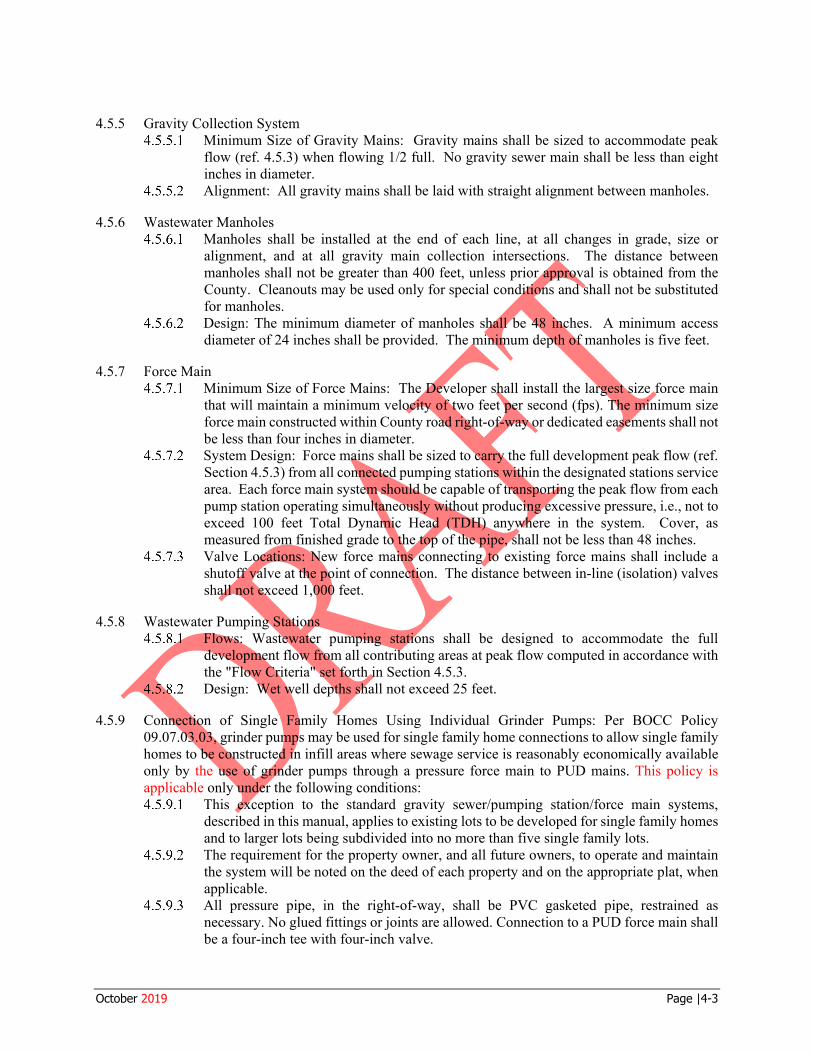
4.5.5.1
4.5.5.2
4.5.6.1
4.5.6.2
4.5.7.1
4.5.7.2
4.5 .7.3
4.5.9.1
4.5.9.2
4.5.9.3
4.5.5 Gravity Collection System Minimum Size of Gravity Mains: Gravity mains shall be sized to accommodate peak flow (ref. 4.5.3) when flowing 1/2 full. No gravity sewer main shall be less than eight inches in diameter. Alignment: All gravity mains shall be laid with straight alignment between manholes.
4.5.6 Wastewater Manholes Manholes shall be installed at the end of each line, at all changes in grade, size or alignment, and at all gravity main collection intersections. The distance between manholes shall not be greater than 400 feet, unless prior approval is obtained from the County. Cleanouts may be used only for special conditions and shall not be substituted for manholes. Design: The minimum diameter of manholes shall be 48 inches. A minimum access diameter of 24 inches shall be provided. The minimum depth of manholes is five feet.
4.5.7 Force Main Minimum Size of Force Mains: The Developer shall install the largest size force main that will maintain a minimum velocity of two feet per second (fps). The minimum size force main constructed within County road right-of-way or dedicated easements shall not be less than four inches in diameter. System Design: Force mains shall be sized to carry the full development peak flow (ref. Section 4.5.3) from all connected pumping stations within the designated stations service area. Each force main system should be capable of transporting the peak flow from each pump station operating simultaneously without producing excessive pressure, i.e., not to exceed 100 feet Total Dynamic Head (TDH) anywhere in the system. Cover, as measured from finished grade to the top of the pipe, shall not be less than 48 inches. Valve Locations: New force mains connecting to existing force mains shall include a shutoff valve at the point of connection. The distance between in-line (isolation) valves shall not exceed 1,000 feet.
4.5.8 Wastewater Pumping Stations Flows: Wastewater pumping stations shall be designed to accommodate the full development flow from all contributing areas at peak flow computed in accordance with the "Flow Criteria" set forth in Section 4.5.3. Design: Wet well depths shall not exceed 25 feet.
4.5.9 Connection of Single Family Homes Using Individual Grinder Pumps: Per BOCC Policy 09.07.03.03, grinder pumps may be used for single family home connections to allow single family homes to be constructed in infill areas where sewage service is reasonably economically available only by the use of grinder pumps through a pressure force main to PUD mains. This policy is applicable only under the following conditions:
This exception to the standard gravity sewer/pumping station/force main systems, described in this manual, applies to existing lots to be developed for single family homes and to larger lots being subdivided into no more than five single family lots. The requirement for the property owner, and all future owners, to operate and maintain the system will be noted on the deed of each property and on the appropriate plat, when applicable. All pressure pipe, in the right-of-way, shall be PVC gasketed pipe, restrained as necessary. No glued fittings or joints are allowed. Connection to a PUD force main shall be a four-inch tee with four-inch valve.
October 2019 Page |4-3
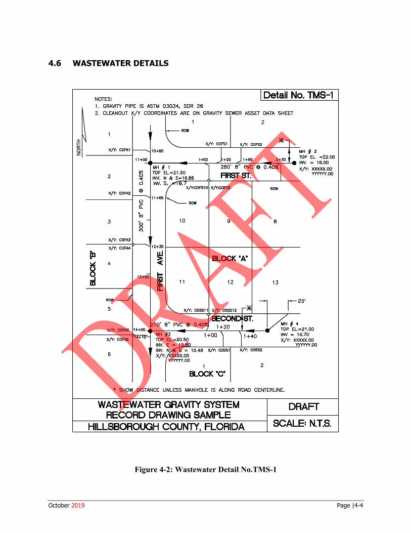
b: 0 z
NOTES: Detail No. TMS-1 1 . GRAVITY PIPE IS ASTM 03034, SOR 26
2. CLEANOUT X/Y COORDINATES ARE ON GRAVITY SEWER ASSET DATA SHEET
in . ~
~
X/Y: COFA1
2
X/Y: COFA2
3
X/Y: COFA3
X/Y: COFM
4
ROW
5
X/Y: COFA5
X/Y: COFA6
6
2
ROW
X/Y: COF'S1 X/Y: COF'S2 * 10+80 MH # 2
11+00 1+00 +20 1 +60 2+30 TOP EL =22.00 -e----1---__,,,,.-.c._-----,---"""------.....,,.---'-a INV. = 18.00
~ 0 v c:i @
13+00
280' 8" PVC @ 0.40% X/Y: XXXXX.00
RAST ST. YYYYYY.00
X/Y:COF'S10 X/Y:COF'S9
ROW
10 9
12+35
~ BLOCK "A"
~ 11 12 [[
1 O' 8" PVC @ 0.40 1+20
MH #3 1 +00 TOP EL.=20.50
ROW
8
13
r20' MH # 4 TOP EL.=21.00 INV = 16.70 X/Y: XXXXX.00
.00 INV. E =:,..i.:1 .!&lo'------.-,1._.---c½-:--:-:c::-=----..LL INV. N S = 15.48 X/Y: COSS1 X/Y: XXXX.00
YYYYYY.00 1
BLOCK •c• 2
* SHOW DISTANCE UNLESS MANHOLE IS ALONG ROAD CENTERLINE.
WASTEWATER GRAVITY SYSTEM RECORD DRAWING SAMPLE
DRAFT
HILLSBOROUGH COUNTY, FLORIDA SCALE= N.T.S.
4.6 WASTEWATER DETAILS
Figure 4-2: Wastewater Detail No.TMS-1
October 2019 Page |4-4
Section 5.0 SPECIFICATIONS FOR RECLAIMED WATER SYSTEMS DESIGN
5.1 GENERAL
5.1.1 The following specification covers the general design, review of plans and specifications, and acceptance of reclaimed water distribution systems, reclaimed water transmission main extensions,
extensions, and all appurtenant items shall be designed in accordance with the applicable regulations of Hillsborough County, the Hillsborough County Department of Health, the Florida Department of Environmental Protection and the standards established herein.
Distribution System (on site): Hillsborough County PUD shall own and maintain all portions of the
individual curb stop, service box, and/or meter.
in Appendix 3, shall be followed.
and all appurtenant items which are to be owned and maintained by Hillsborough County. This includes developer-built on-site reclaimed water distribution systems in residential subdivisions and commercial developments, off-site transmission main extensions to development sites, and on-site requirements for large reclaimed water users.
5.1.2 The Public Utilities Department (PUD) Technical Specification 339001 “Reclaimed Water Mains & Appurtenances” shall provide additional clarification regarding design details, materials of construction, installation and acceptance requirements. If further clarification is needed, contact the Site Engineering Review Section of the Development Services Department (DSD) or the Utility Design Section of the PUD.
5.1.3 All improvements and modifications made to the Hillsborough County reclaimed water system shall be done in accordance with plans approved by the Site Engineering Review Section of DSD. Material, workmanship and installation shall comply with PUD Technical Specification 339001.
5.2 PLANS PREPARATION
5.2.1 Reclaimed water distribution (on-site) systems, reclaimed water transmission main (off-site)
5.2.2 reclaimed water distribution system including the master meter and up to and including the
When a distribution main will serve existing or future developments beyond the borders of the proposed site, the County may request oversizing. If the County determines that a line needs to be “Oversized”, the procedures for sizing and reimbursement, as outlined
The distribution system or any portion thereof, which is to become the property and sole responsibility of Hillsborough County PUD, shall be designed and constructed within a public right-of-way or easement which may be used for said purpose. The primary feed for the distribution system shall be routed within County road right-of-way. A secondary feed may be routed within a utility easement dedicated to the County (design exception). Refer to the Hillsborough County Public Works Transportation Technical Manual Drawings, latest edition, for Recommended Utility Locations, TS-1.
5.2.3 Transmission System (off site): Hillsborough County PUD shall own and maintain the transmission system. The transmission main shall be designed and constructed within the public right-of-way.
5.2.4 The reclaimed water distribution system or reclaimed water main extension shall be designed and constructed in accordance with the requirements specified in PUD Technical Specification 339001.
October 2019 Page |5-1
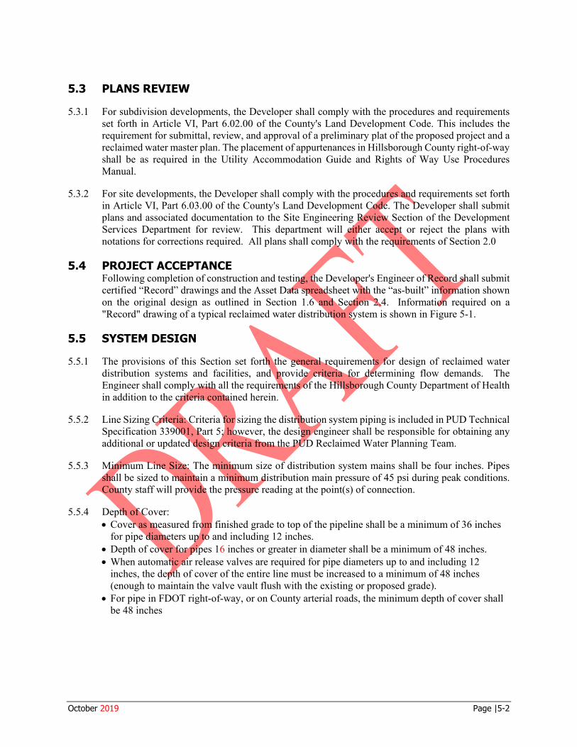
For site developments, the Developer shall comply with the procedures and requirements set forth in Article VI, Part 6.03.00 of the County's Land Development Code. The Developer shall submit plans and associated documentation to the Site Engineering Review Section of the Development Services Department for review. This department will either accept or reject the plans with notations for corrections required. All plans shall comply with the requirements of Section 2.0
PROJECT ACCEPTANCE Following completion of construction and testing, the Developer's Engineer of Record shall submit certified “Record” drawings and the Asset Data spreadsheet with the “as-built” information shown on the original design as outlined in Section 1.6 and Section 2.4. Information required on a "Record" drawing of a typical reclaimed water distribution system is shown in Figure 5-1.
SYSTEM DESIGN
The provisions of this Section set forth the general requirements for design of reclaimed water distribution systems and facilities, and provide criteria for determining flow demands. The Engineer shall comply with all the requirements of the Hillsborough County Department of Health in addition to the criteria contained herein.
Line Sizing Criteria: Criteria for sizing the distribution system piping is included in PUD Technical Specification 339001, Part 5; however, the design engineer shall be responsible for obtaining any additional or updated design criteria from the PUD Reclaimed Water Planning Team.
Minimum Line Size: The minimum size of distribution system mains shall be four inches. Pipes shall be sized to maintain a minimum distribution main pressure of 45 psi during peak conditions. County staff will provide the pressure reading at the point(s) of connection.
Depth of Cover: • Cover as measured from finished grade to top of the pipeline shall be a minimum of 36 inches
for pipe diameters up to and including 12 inches. • Depth of cover for pipes 16 inches or greater in diameter shall be a minimum of 48 inches. • When automatic air release valves are required for pipe diameters up to and including 12
inches, the depth of cover of the entire line must be increased to a minimum of 48 inches
5.3 PLANS REVIEW
5.3.1 For subdivision developments, the Developer shall comply with the procedures and requirements set forth in Article VI, Part 6.02.00 of the County's Land Development Code. This includes the requirement for submittal, review, and approval of a preliminary plat of the proposed project and a reclaimed water master plan. The placement of appurtenances in Hillsborough County right-of-way shall be as required in the Utility Accommodation Guide and Rights of Way Use Procedures Manual.
5.3.2
5.4
5.5
5.5.1
5.5.2
5.5.3
5.5.4
(enough to maintain the valve vault flush with the existing or proposed grade). • For pipe in FDOT right-of-way, or on County arterial roads, the minimum depth of cover shall
be 48 inches
October 2019 Page |5-2
It: 0 z
Detail No. TMR-1 EXIST. 12' --::::--- - 8• GV RECLAIMED~ · · TIWISMISSION MAIN 1 o+oo
POINT OF CONNECTION: X: XXXXX.XX Y: YYYYYY. YY Z: ZZ.ZZ
2 ROW
RECLAIMED WATER METER BOX
RECLAIMED WATER METER BOX 11+00
2
ROW
3
RECLAIMED WATER METER BOX
. m . § 4
II
m
5
RECLAIMED WATER SERVICE BOX
6
2• BLOW OFF
X/Y: XXXXX.XX YYYYYY.YY
~ "' z "' a ~ a:
12+00
~ 13+00
0
15+00
8
RECLAIMED WA R METER BOX ROW
10 9 8
ROW
BLOCK 'A'
11 12 13
RECLAIMED WATER METER BOX II ..._
6" G.V.
M:>ST.
BLOCK 'C' NOTES: 1. RECLAIMED PIPE IS PVC AWWA C900, DR18
2. FITTING X/Y /Z COORDINATES ARE ON RECLAIMED WATER ASSET DATA SPREAOSHEETS
RECLAIMED WATER DISTRIBUTION RECORD DRAWING SAMPLE
DRAFT
HILLSBOROUGH COUNTY, FLORIDA SCALE= N.T.S.
5.6 RECLAIMED WATER DETAILS
Figure 5-1: Reclaimed Water Detail No. TMR-1
October 2019 Page |5-3
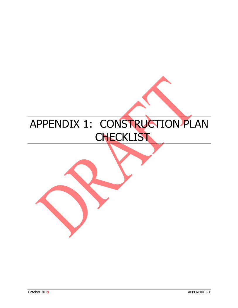
APPENDIX 1: CONSTRUCTION PLAN CHECKLIST
October 2019 APPENDIX 1-1
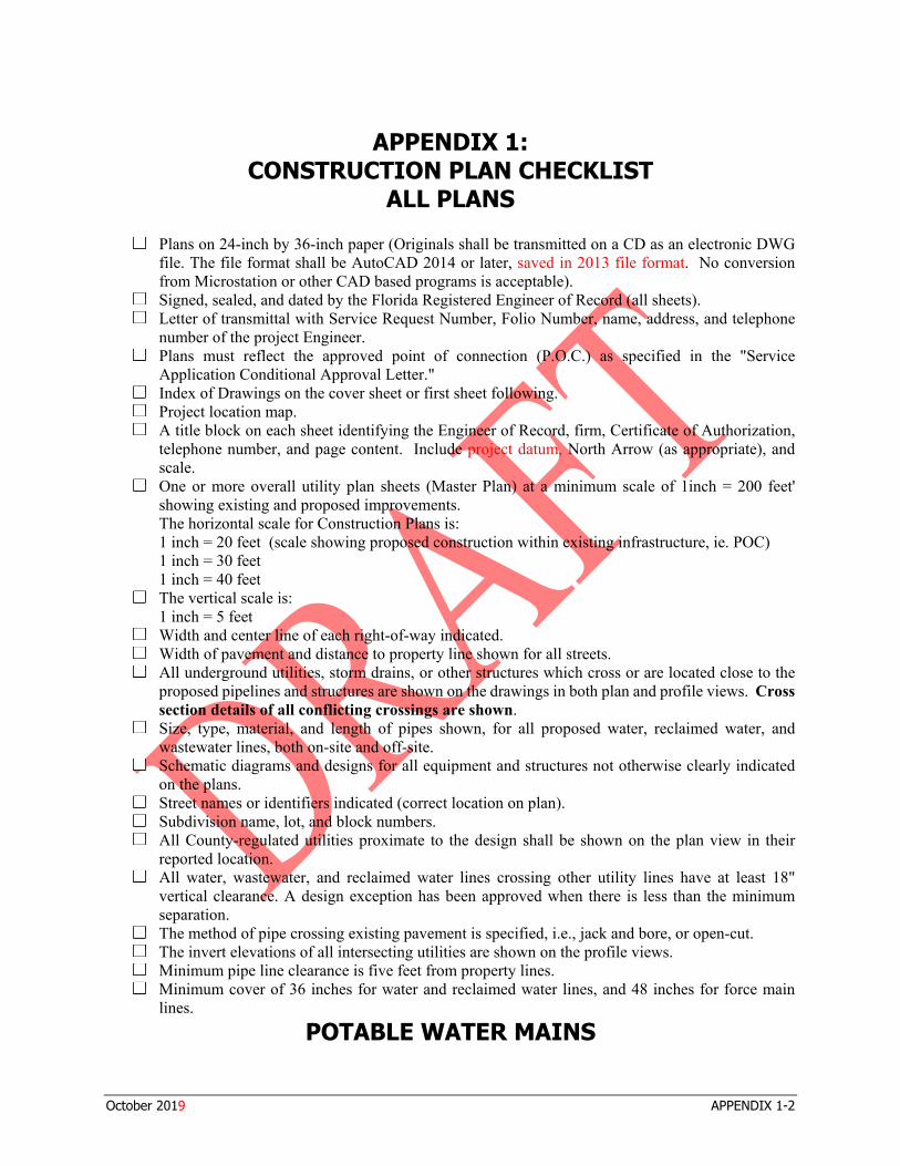
□
□ □
□
□ □ □
□
□
□ □ □
□
□ □ □
□
□ □ □ □
APPENDIX 1: CONSTRUCTION PLAN CHECKLIST
ALL PLANS
Plans on 24-inch by 36-inch paper (Originals shall be transmitted on a CD as an electronic DWG file. The file format shall be AutoCAD 2014 or later, saved in 2013 file format. No conversion from Microstation or other CAD based programs is acceptable). Signed, sealed, and dated by the Florida Registered Engineer of Record (all sheets). Letter of transmittal with Service Request Number, Folio Number, name, address, and telephone number of the project Engineer. Plans must reflect the approved point of connection (P.O.C.) as specified in the "Service Application Conditional Approval Letter." Index of Drawings on the cover sheet or first sheet following. Project location map. A title block on each sheet identifying the Engineer of Record, firm, Certificate of Authorization, telephone number, and page content. Include project datum, North Arrow (as appropriate), and scale. One or more overall utility plan sheets (Master Plan) at a minimum scale of 1inch = 200 feet' showing existing and proposed improvements. The horizontal scale for Construction Plans is: 1 inch = 20 feet (scale showing proposed construction within existing infrastructure, ie. POC) 1 inch = 30 feet 1 inch = 40 feet The vertical scale is: 1 inch = 5 feet Width and center line of each right-of-way indicated. Width of pavement and distance to property line shown for all streets. All underground utilities, storm drains, or other structures which cross or are located close to the proposed pipelines and structures are shown on the drawings in both plan and profile views. Cross section details of all conflicting crossings are shown. Size, type, material, and length of pipes shown, for all proposed water, reclaimed water, and wastewater lines, both on-site and off-site. Schematic diagrams and designs for all equipment and structures not otherwise clearly indicated on the plans. Street names or identifiers indicated (correct location on plan). Subdivision name, lot, and block numbers. All County-regulated utilities proximate to the design shall be shown on the plan view in their reported location. All water, wastewater, and reclaimed water lines crossing other utility lines have at least 18" vertical clearance. A design exception has been approved when there is less than the minimum separation. The method of pipe crossing existing pavement is specified, i.e., jack and bore, or open-cut. The invert elevations of all intersecting utilities are shown on the profile views. Minimum pipe line clearance is five feet from property lines. Minimum cover of 36 inches for water and reclaimed water lines, and 48 inches for force main lines.
POTABLE WATER MAINS
October 2019 APPENDIX 1-2
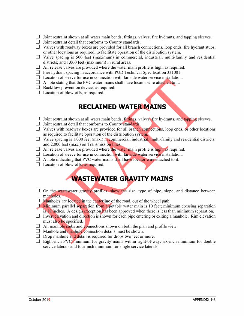
□ □ □
□
□ □ □ □ □ □
□ □ □
□
□ □ □ □
□
□
□ □ □ □
Joint restraint shown at all water main bends, fittings, valves, fire hydrants, and tapping sleeves. Joint restraint detail that conforms to County standards. Valves with roadway boxes are provided for all branch connections, loop ends, fire hydrant stubs, or other locations as required, to facilitate operation of the distribution system. Valve spacing is 500 feet (maximum) in commercial, industrial, multi-family and residential districts; and 1,000 feet (maximum) in rural areas. Air release valves are provided where the water main profile is high, as required. Fire hydrant spacing in accordance with PUD Technical Specification 331001. Location of sleeve for use in connection with far side water service installation. A note stating that the PVC water mains shall have locator wire attached to it. Backflow prevention device, as required. Location of blow-offs, as required.
RECLAIMED WATER MAINS
Joint restraint shown at all water main bends, fittings, valves, fire hydrants, and tapping sleeves. Joint restraint detail that conforms to County standards. Valves with roadway boxes are provided for all branch connections, loop ends, or other locations as required to facilitate operation of the distribution system. Valve spacing is 1,000 feet (max.) in commercial, industrial, multi-family and residential districts; and 2,000 feet (max.) on Transmission lines. Air release valves are provided where the water main profile is high, as required. Location of sleeve for use in connection with far side water service installation. A note indicating that PVC water mains shall have locator wire attached to it. Location of blow-offs, as required.
WASTEWATER GRAVITY MAINS
On the wastewater gravity profiles, show the size, type of pipe, slope, and distance between manholes. Manholes are located in the centerline of the road, out of the wheel path. Minimum parallel separation from a potable water main is 10 feet; minimum crossing separation is 18 inches. A design exception has been approved when there is less than minimum separation. Invert elevation and direction is shown for each pipe entering or exiting a manhole. Rim elevation must also be specified. All manhole stubs and connections shown on both the plan and profile view. Manhole and manhole connection details must be shown. Drop manhole and detail is required for drops two feet or more. Eight-inch PVC minimum for gravity mains within right-of-way, six-inch minimum for double service laterals and four-inch minimum for single service laterals.
October 2019 APPENDIX 1-3
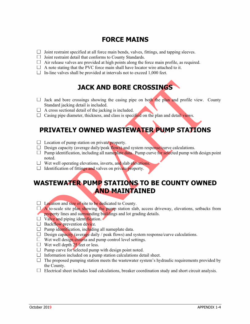
□ □ □ □ □
□
□ □
□ □ □
□ □
□ □ □ □ □ □ □ □ □
□
FORCE MAINS
Joint restraint specified at all force main bends, valves, fittings, and tapping sleeves. Joint restraint detail that conforms to County Standards. Air release valves are provided at high points along the force main profile, as required. A note stating that the PVC force main shall have locator wire attached to it. In-line valves shall be provided at intervals not to exceed 1,000 feet.
JACK AND BORE CROSSINGS
Jack and bore crossings showing the casing pipe on both the plan and profile view. County Standard jacking detail is included. A cross sectional detail of the jacking is included. Casing pipe diameter, thickness, and class is specified on the plan and detail views.
PRIVATELY OWNED WASTEWATER PUMP STATIONS
Location of pump station on private property. Design capacity (average daily/peak flows) and system response/curve calculations. Pump identification, including all nameplate data. Pump curve for selected pump with design point noted. Wet well operating elevations, inverts, and slab elevations. Identification of fittings and valves on private property.
WASTEWATER PUMP STATIONS TO BE COUNTY OWNED AND MAINTAINED
Location and size of site to be dedicated to County. A to-scale site plan showing the pump station slab, access driveway, elevations, setbacks from property lines and surrounding buildings and lot grading details. Valve and piping identification. Backflow prevention device. Pump identification, including all nameplate data. Design capacity (average daily / peak flows) and system response/curve calculations. Wet well design criteria and pump control level settings. Wet well depth 25 feet or less. Pump curve for selected pump with design point noted. Information included on a pump station calculations detail sheet. The proposed pumping station meets the wastewater system’s hydraulic requirements provided by the County. Electrical sheet includes load calculations, breaker coordination study and short circuit analysis.
October 2019 APPENDIX 1-4

APPENDIX 2: CONSTRUCTION FEATURE INFORMATION AND ASSET DATA SPREADSHEETS
EXHIBIT PIPE ASSETS
EXHIBIT PROJECT NODE MAP
POTABLE WATER ASSET DATA
GRAVITY WASTEWATER ASSET DATA
FORCE MAIN WASTEWATER ASSET DATA
PUMP STATION WASTEWATER ASSET DATA
RECLAIMED WATER ASSET DATA
October 2019 APPENDIX 2
APPENDIX 2: CONSTRUCTION FEATURE INFORMATION AND
ASSET DATA SPREADSHEETS
Hillsborough County Public Utilities Department (PUD) requires all Record Drawing submittal packages to include a filled out copy of the department’s Asset Data spreadsheets which are available on our website.
The spreadsheets are macro driven (Excel program security may need to be adjusted to accommodate) and requires the user to identify the Project Type before selecting the proper spreadsheet. All applicable sections of the spreadsheet are to be filled out in their entirety.
Users needing additional lines for data entry should click on any colored cell on the left side of the screen with the exception of the first one. Multiple rows can be inserted by highlighting additional cells. Using the Insert Row function on the Home tab of the menu ribbon. users can insert as many rows as needed while retaining the special formatting features of the spreadsheet.
It should be noted that all X-Y-Z coordinate data required for the spreadsheet must be tied to the 1983 Florida West State Plane coordinate system and the 1988 NAVD vertical datum. All horizontal and vertical data shall be accurate to 5/100ths of a foot or 1.5 centimeters.
Contractors electing to use RTK GPS for field data collection are encouraged to tie into the Florida Permanent Reference Network maintained by the Florida Department of Transportation. Registration is required and all appropriate access information is available on the FPRN website.
Any other questions pertaining to the data reporting requirements included in this section should be directed to Anthony Artau, Utility Planning Records, 813-612-7782.
Please refer to the Hillsborough County Website at Hillsborough County, FL - Official Website -Technical Manual for a link to the Asset Data Spreadsheets and Exhibits.
October 2019 APPENDIX 2-1
APPENDIX 3: OVERSIZING PROCESS AND OVERSIZING
REIMBURSEMENT PROGRAM
October 2019 APPENDIX 3
APPENDIX 3: OVERSIZING PROCESS AND
OVERSIZING REIMBURSEMENT PROGRAM
The County requires new development to construct facilities that are "oversized", if analyses of the future needs in the area of the development show a need for oversizing. The Applicant shall be totally responsible for all of the costs to design, permit, and construct the oversized facilities. An Oversizing Reimbursement Program has been established to provide a system for reimbursing the Applicant for the oversized portion of the facilities as other projects connect to, and benefit from, the oversized facilities. This program will be maintained by the County, pursuant to agreements between the County and the Applicant. In order to establish a consistent policy for conducting all oversizings, a standard oversizing agreement will be used.
All future utility customers in the oversizing service areas shall be required to contribute a pro rata share of the total cost of the oversized facilities. The Oversizing Fee is payable at the time of Capacity Fee payment. Funds collected through the Oversizing Reimbursement Program will be repaid to the Applicant who funded the installation. The oversize reimbursement period is from the date that the facility is initially placed into service until the facility is fully reimbursed, but not to exceed a period of 10 years, unless otherwise provided in the Applicant's agreement with the County. Total reimbursements to the Applicant who funded the installation of the oversized facilities shall not exceed the total costs minus the Applicant's pro rata share.
The Oversizing Process and the Oversizing Reimbursement Program diagrams follow.
October 2019 APPENDIX 3-1
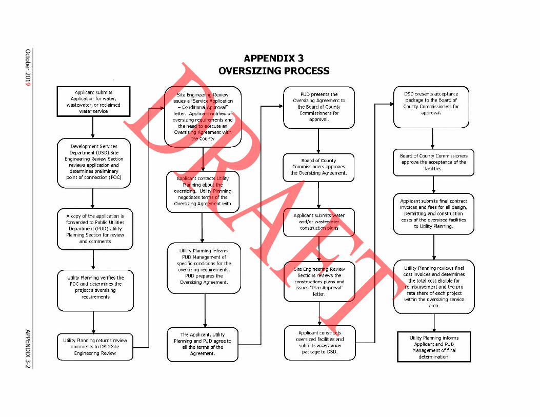
t submits /' Application for water,
wastewater, or reclaimed ,........... water service
' / -.......
Development Services Department (DSD) Site
Engineering Review Section reviews application and determines preliminary /
point of connection ( POC)
\. ,J
' / ' \.
A copy of the application is forwarded to Public Utilities
Department (PUD) Utility Planning Section for review
and comments '\.. , r
•• / ......
Utility Planning verifies the POC and determines the
project's oversizing '\.. requirements
\. ,
' ,
Utility Planning returns review comments to DSD Site --Engineering Review
'
APPENDIX 3 OVERSIZING PROCESS
~ / Site Engineering Review PUD presents the
issues a "Service Application Oversizing Agreement to
- Conditional Approval" .
the Board of County . letter. Applicant notified of Commissioners for oversizing requi rements and approval.
the need to execute an '\..
Oversizing Agreement with the County
~
Board of County
' Commissioners approves
...... the Oversizing Agreement. Applicant contacts Utili ty
Planning about the oversizing. Utility Planning
negotiates terms of the Oversizing Agreement with
,J
Applicant submits water and/or wastewater construction plans
' ' Utility Planning informs
PUD Management of .~ specific conditions for the , oversizing requiremen ts . Site Engineering Review
PUD prepares the Sections reviews the Oversizing Agreement. constructions plans and
,) issues "Plan Approval "
letter.
'"
'~ r The Applicant, Utility Applicant constructs
Planning and PUD agree to oversized facilities and
all the terms of the submits acceptance
Agreement. package to DSD.
'-
-.... I "I
DSD presents acceptance
i------t package to the Board of
County Commissioners for approval.
,J \. ,
' Board of County Commissioners approve the acceptance of the
facilities.
~ .... Applicant submits final contract invoices and fees for all design,
permitting and construction costs of the oversized facilities
to Utility Planning. '- ,J
' / --....., Utility Planning reviews final cost invoices and determines
the total cost eligible for reimbursement and the pro rata share of each project
.,J within the oversizing service
'"" area.
Utility Planning informs Applicant and PUD
Management of final determination.
October 2019
APPEND
IX 3-2
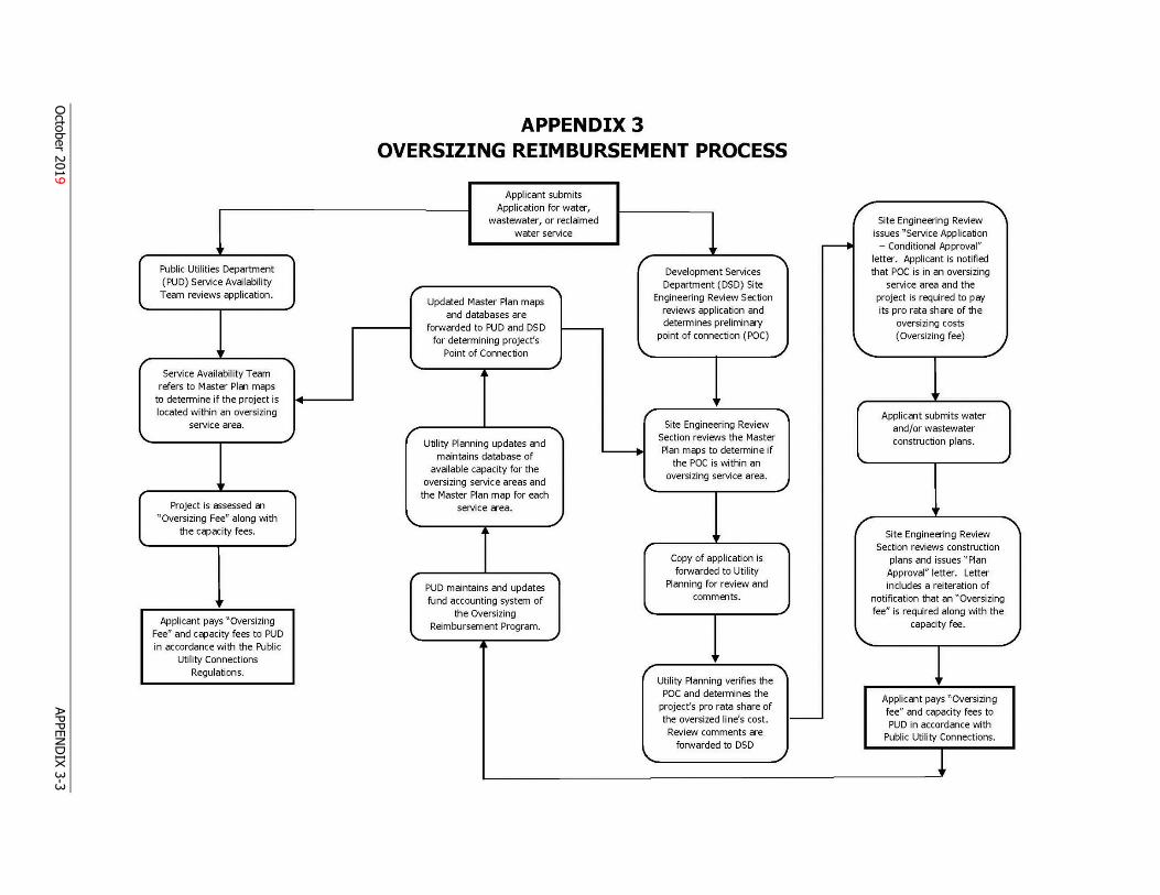
3 OVERSIZING REIMBURSEMENT PROCESS
Applicant submits Application for water, /
Site Engineering Review wastewater, or reclaimed water service issues "Service Application
' ;-----t - Conditional Approval" letter. Applicant is notified r ' that POC is in an oversizing Development Services Public Utili t ies Department
Department (DSD) Site service area and the (PUD) Service Availability r ' Engineering Review Section project is required to pay Team reviews ~plication.
Updated Master Plan maps reviews ~plication and its pro rata share of the and databases are
forwarded to PUD and DSD determines preliminay oversizing costs
for determining project's point of connection ( POC) (Oversizing fee)
' Point of Connection ' r ' '- ., Service Availabil ity Team ~
refers to Master Plan maps to determine if the project is ~ I, r
Applicant submits water r located within an oversizing Site Engineering Review and/or wastewater service area. r ' Section reviews the Master construction plans. ' ~
Utility Planning updates and Plan m~s to determine if
maintains database of . the POC is within an ....
available capacity for the oversizing service area.
oversizing service areas and
' _J ' the Master Plan map for each Project is assessed an service area. l'
/ ' " Oversizing Fee" along with \. ~
Site Engineering Review the c~acity fees. • r ... Section reviews construction Copy of application is plans and issues " Plan forwarded to Utility Approval" letter. Letter
PUD maintains and updates Planning for review and includes a reiterat ion of
' fund accounting system of comments. notification that an "Oversizing ~ fee" is required along with the the Oversizing
capacity fee. Applicant pays "Oversizing Reimbursement Program.
\.. .J Fee" and c~acity fees to PUD ....
l ' in accordance w ith the Public .. Utility Connections
I' "I Regulations. Utility Planning verifies the
POC and determines the Applicant pays "Oversizing project's pro rata share of fee" and capacity fees to the oversized line's cost. - PUD in accordance with Review comments are Public Utility Connections.
forwarded to DSD '- !
October 2019
APPEND
IX 3-3
APPENDIX 4: CONNECTION FEASIBILITY FOR 3 ERC’S OR LESS
October 2019 APPENDIX 4- 1
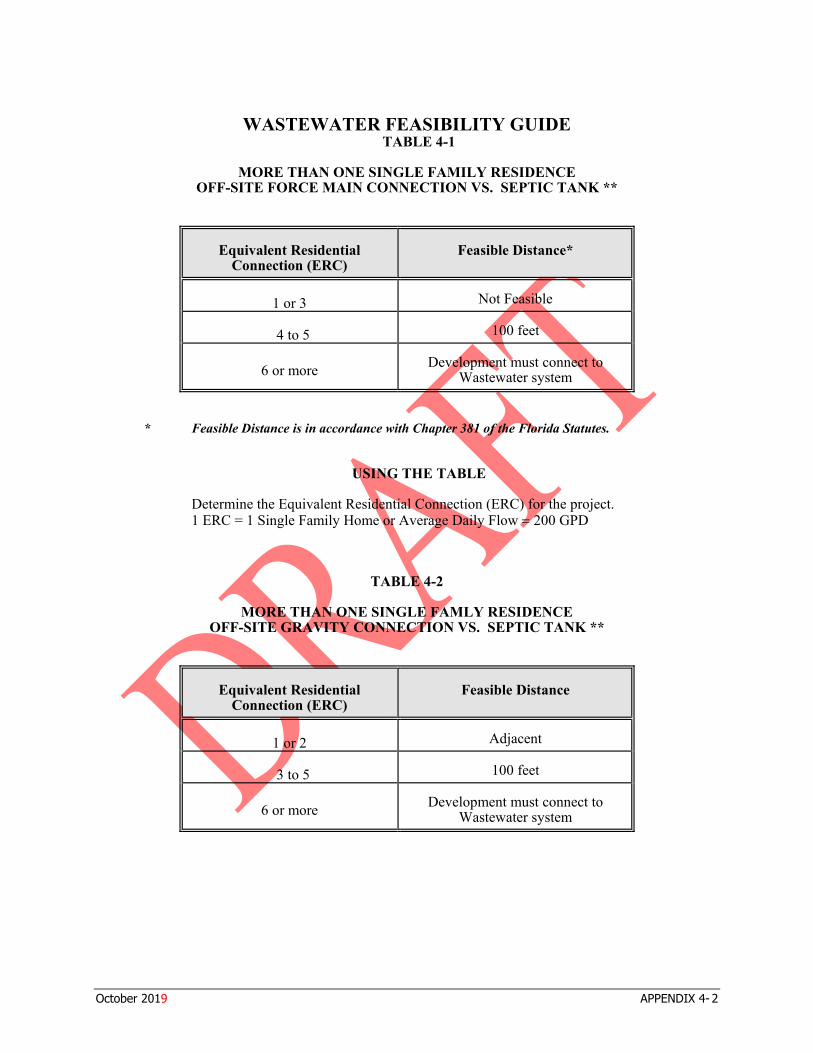
WASTEWATER FEASIBILITY GUIDE TABLE 4-1
MORE THAN ONE SINGLE FAMILY RESIDENCE OFF-SITE FORCE MAIN CONNECTION VS. SEPTIC TANK **
Equivalent ResidentialConnection (ERC)
Feasible Distance*
1 or 3 Not Feasible
4 to 5 100 feet
6 or more Development must connect toWastewater system
* Feasible Distance is in accordance with Chapter 381 of the Florida Statutes.
USING THE TABLE
Determine the Equivalent Residential Connection (ERC) for the project. 1 ERC = 1 Single Family Home or Average Daily Flow = 200 GPD
TABLE 4-2
MORE THAN ONE SINGLE FAMLY RESIDENCE OFF-SITE GRAVITY CONNECTION VS. SEPTIC TANK **
Equivalent ResidentialConnection (ERC)
Feasible Distance
1 or 2 Adjacent
3 to 5 100 feet
6 or more Development must connect toWastewater system
October 2019 APPENDIX 4- 2
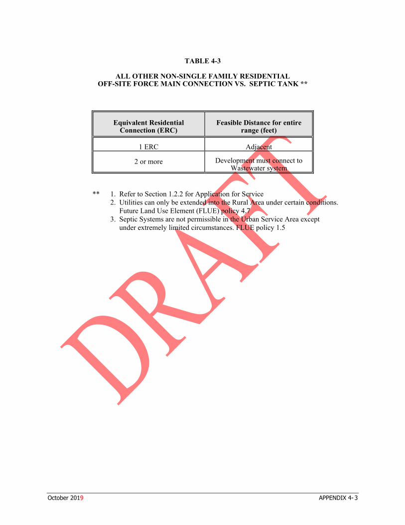
TABLE 4-3
ALL OTHER NON-SINGLE FAMILY RESIDENTIAL OFF-SITE FORCE MAIN CONNECTION VS. SEPTIC TANK **
Equivalent ResidentialConnection (ERC)
Feasible Distance for entire range (feet)
1 ERC Adjacent
2 or more Development must connect to Wastewater system
1. Refer to Section 1.2.2 for Application for Service 2. Utilities can only be extended into the Rural Area under certain conditions.
Future Land Use Element (FLUE) policy 4.7 3. Septic Systems are not permissible in the Urban Service Area except
under extremely limited circumstances. FLUE policy 1.5
**
October 2019 APPENDIX 4- 3