water measurement
DESCRIPTION
Water Measurement. Brady S. McElroy, P.E. USDA-NRCS Lamar, Colorado. Objectives. Why is water measurement important to IWM? Explain some of the mathematics of water measurement Discuss some of the common measuring devices encountered in NRCS work Discuss other opportunities for measurement - PowerPoint PPT PresentationTRANSCRIPT
Water Measurement
Brady S. McElroy, P.E.USDA-NRCS
Lamar, Colorado
Objectives• Why is water measurement important to
IWM?• Explain some of the mathematics of water
measurement• Discuss some of the common measuring
devices encountered in NRCS work• Discuss other opportunities for measurement• Work some example problems
Why is water measurement important?
• Difficult to effectively manage irrigation without measurement
• Positive aspects– Maximize use of available water supply– Reduced cost due to leached nutrients– Reduced environmental impact from over-
irrigation
Why is water measurement important?
• Some measurement may have a negative connotation– Regulatory (mandated by state, etc.)– Billing
Why is water measurement important?
• Water is one of the most precious resources in the West– Increased competition among water users

“Whiskey is for drinking. Water is for fighting over.”
Mark Twain
References
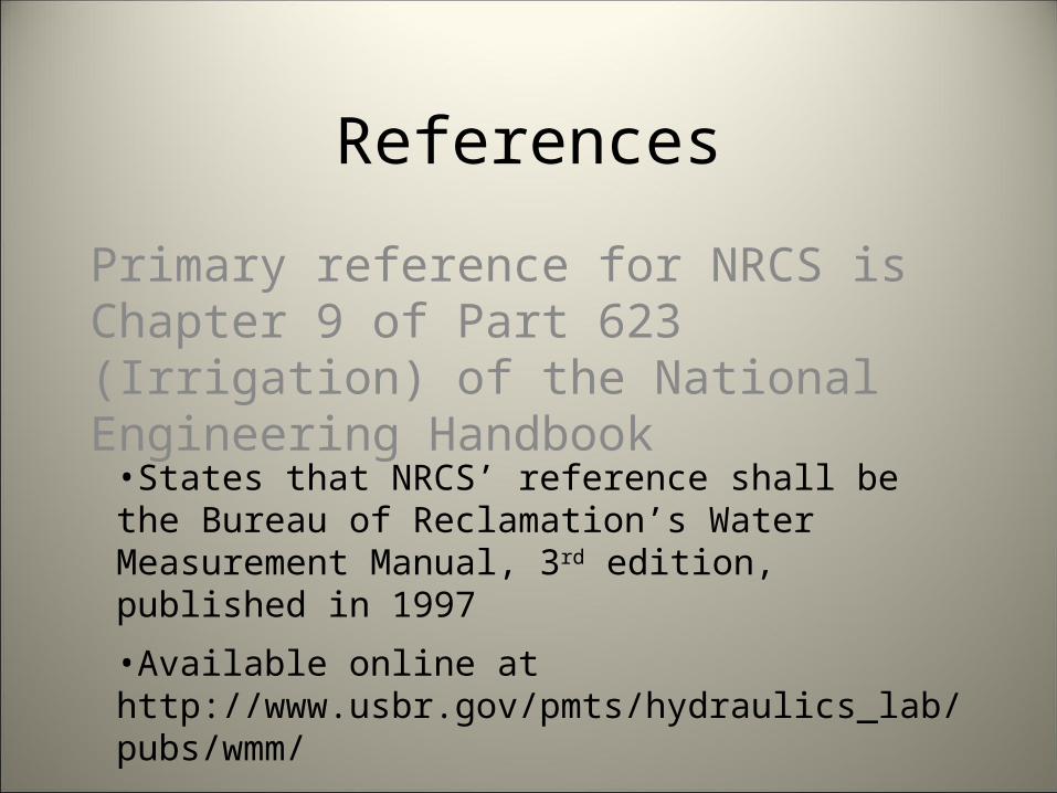
Primary reference for NRCS is Chapter 9 of Part 623 (Irrigation) of the National Engineering Handbook
•States that NRCS’ reference shall be the Bureau of Reclamation’s Water Measurement Manual, 3rd edition, published in 1997
•Available online at http://www.usbr.gov/pmts/hydraulics_lab/pubs/wmm/
References
Other useful references
• Other NRCS documents• Irrigator’s Guides• Extension publications• Hydraulic texts
– King’s Handbook of Hydraulics
Definitions
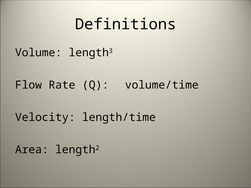
Volume: length3
Flow Rate (Q): volume/time
Velocity: length/time
Area: length2
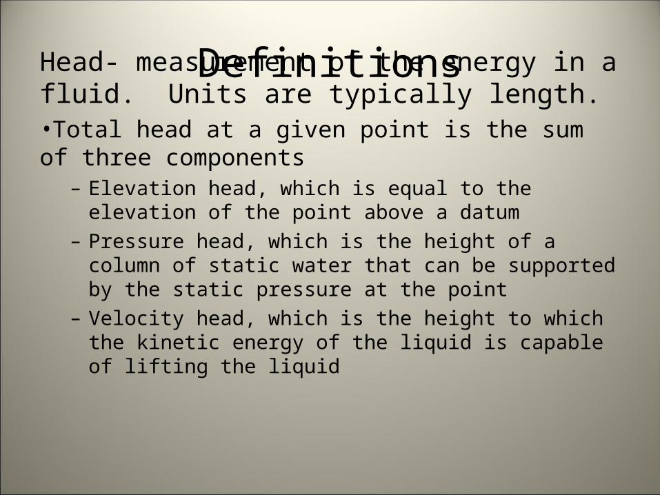
DefinitionsHead- measurement of the energy in a fluid. Units are typically length.•Total head at a given point is the sum of three components
– Elevation head, which is equal to the elevation of the point above a datum
– Pressure head, which is the height of a column of static water that can be supported by the static pressure at the point
– Velocity head, which is the height to which the kinetic energy of the liquid is capable of lifting the liquid
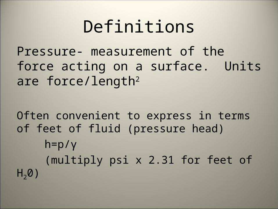
DefinitionsPressure- measurement of the force acting on a surface. Units are force/length2
Often convenient to express in terms of feet of fluid (pressure head)
h=p/γ(multiply psi x 2.31 for feet of H20)
Units
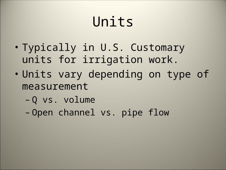
• Typically in U.S. Customary units for irrigation work.
• Units vary depending on type of measurement– Q vs. volume– Open channel vs. pipe flow
Units
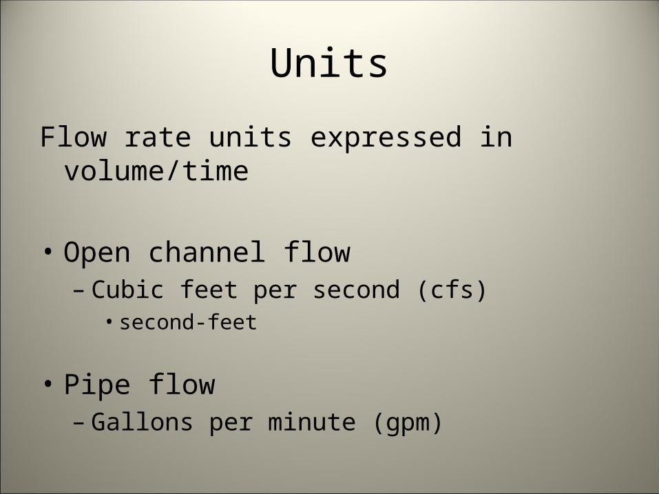
Flow rate units expressed in volume/time
• Open channel flow– Cubic feet per second (cfs)
• second-feet
• Pipe flow– Gallons per minute (gpm)
Units
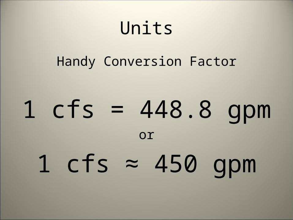
Handy Conversion Factor
1 cfs = 448.8 gpmor
1 cfs ≈ 450 gpm
Units
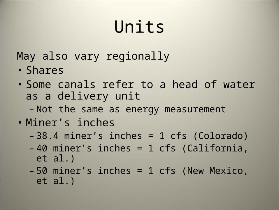
May also vary regionally• Shares• Some canals refer to a head of water as a
delivery unit– Not the same as energy measurement
• Miner’s inches– 38.4 miner’s inches = 1 cfs (Colorado)– 40 miner's inches = 1 cfs (California, et al.)– 50 miner’s inches = 1 cfs (New Mexico, et al.)

Units
A share is not a share is not a share
Canal Allocation/share (cfs)Bessemer 0.0150Colorado 0.0125Rocky Ford Highline 0.180Oxford 0.0960Otero 0.050Holbrook 0.0250Catlin 0.0180Rocky Ford 0.140Fort Lyon 0.0150Amity 5 cfs at 0.6 hr/shareLamar 0.0100

Units
Volume units are often expressed in units of area x depth or depth
Acre-foot = volume of water that would cover 1 acre to a depth of 1 foot• 12 acre-inches• 43,560 cubic feet• 325,851 gallons
Units
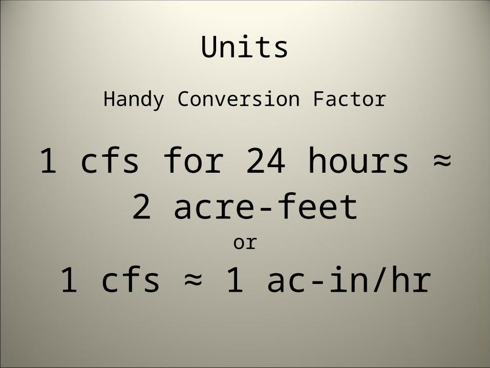
Handy Conversion Factor
1 cfs for 24 hours ≈ 2 acre-feet
or
1 cfs ≈ 1 ac-in/hr
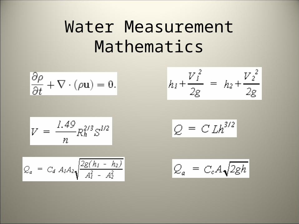
Water Measurement Mathematics
Water Measurement Mathematics
Water Measurement Mathematics
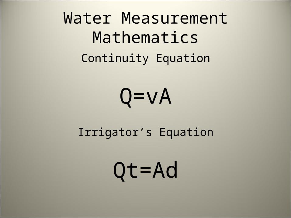
Continuity Equation
Q=vAIrrigator’s Equation
Qt=Ad
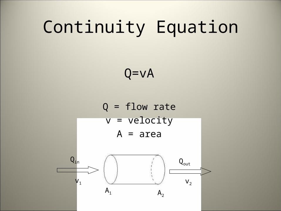
v1 v2
Qin Qout
A1 A2
Continuity Equation
Q=vA
Q = flow ratev = velocity
A = area

Continuity Equation
Q=vA
v=Q/A
A=Q/v
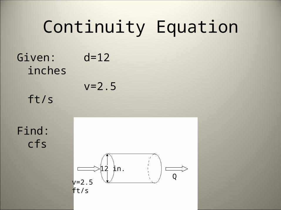
Continuity Equation
Given: d=12 inchesv=2.5 ft/s
Find: Q in cfs
Qv=2.5 ft/s
12 in.
Qv=2.5 ft/s
12 in.
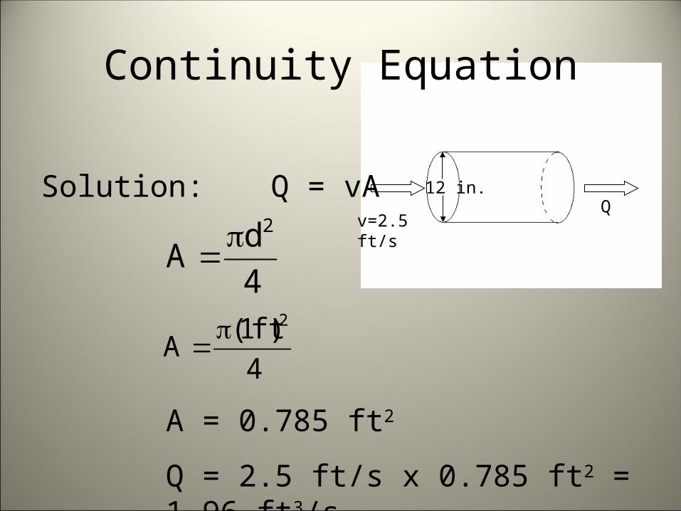
Continuity Equation
Solution: Q = vA
4
2dA
4
1 2)ft(A
A = 0.785 ft2
Q = 2.5 ft/s x 0.785 ft2 = 1.96 ft3/s
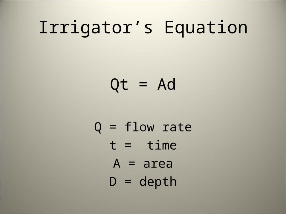
Irrigator’s Equation
Qt = Ad
Q = flow ratet = timeA = area
D = depth
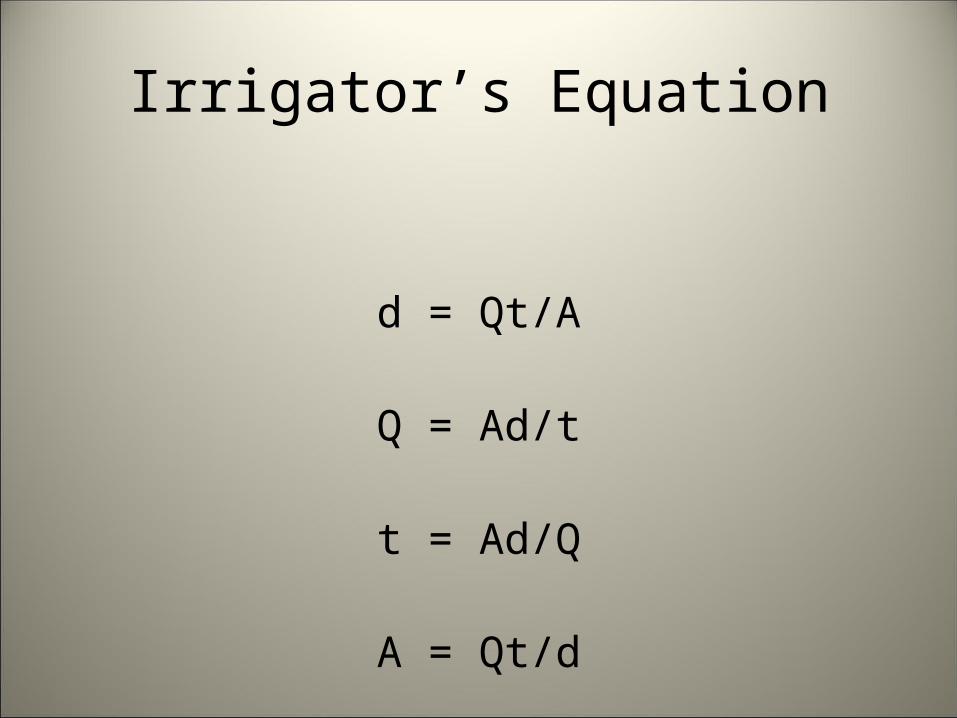
Irrigator’s Equation
d = Qt/A
Q = Ad/t
t = Ad/Q
A = Qt/d
Irrigator’s Equation
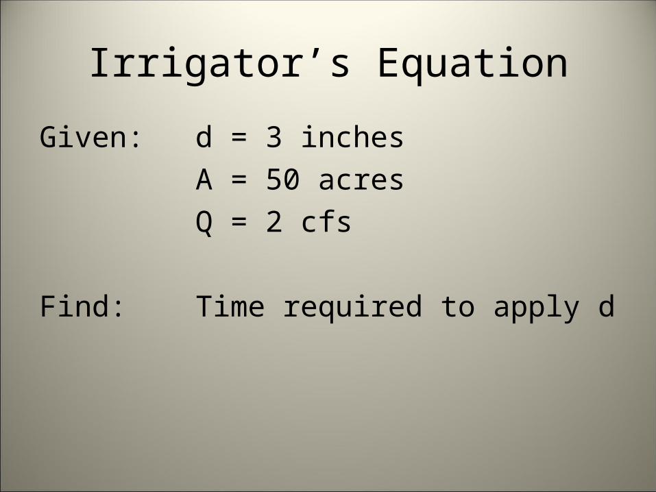
Given: d = 3 inchesA = 50 acresQ = 2 cfs
Find: Time required to apply d
Irrigator’s Equation
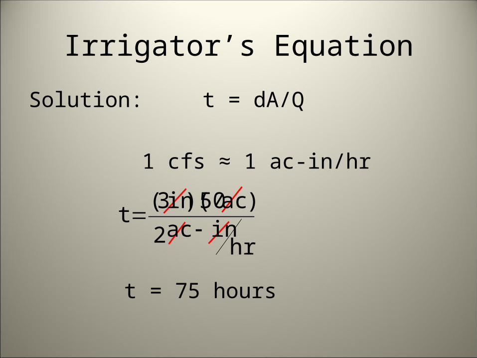
Solution: t = dA/Q
1 cfs ≈ 1 ac-in/hr
t = 75 hours
hrinac
)ac)(in(t
2
503
Irrigator’s Equation
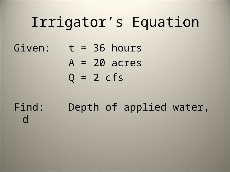
Given: t = 36 hoursA = 20 acresQ = 2 cfs
Find: Depth of applied water, d
Irrigator’s Equation
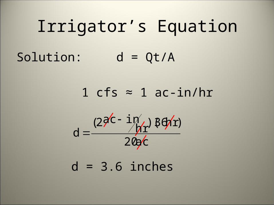
Solution: d = Qt/A
1 cfs ≈ 1 ac-in/hr
d = 3.6 inches
ac
)hr)(hrinac(
d20
362
Water Measurement Devices
Most water measurement devices either sense or measure velocity, or measure either pressure or head.
Tables, charts, or equations are then used to calculate the corresponding discharge
Water Measurement Devices
Devices that sample or sense velocity
• Current meters• Propeller meters• Vane deflection meters• Float and stopwatch
Water Measurement Devices
Devices that measure head or pressure– Open channel devices commonly use h– Pipeline devices may use p
• Flumes• Orifices• Venturi meters• Weirs
– Velocity is computed from h, so weirs are classifed as head measuring devices
Open Channel Devices
• Weirs• Flumes• Submerged Orifices• Other devices
Weirs
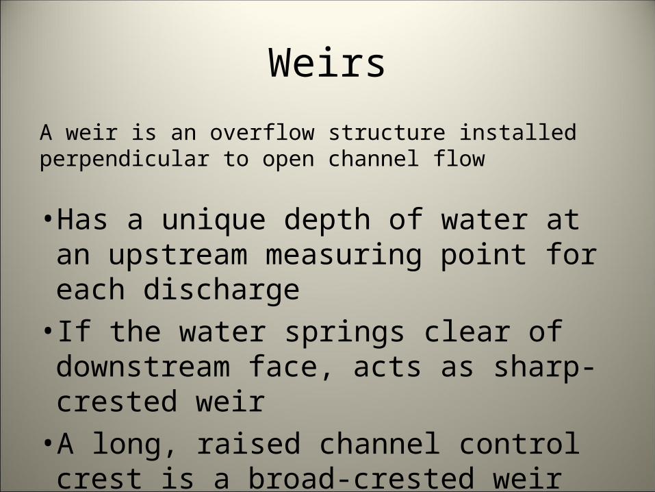
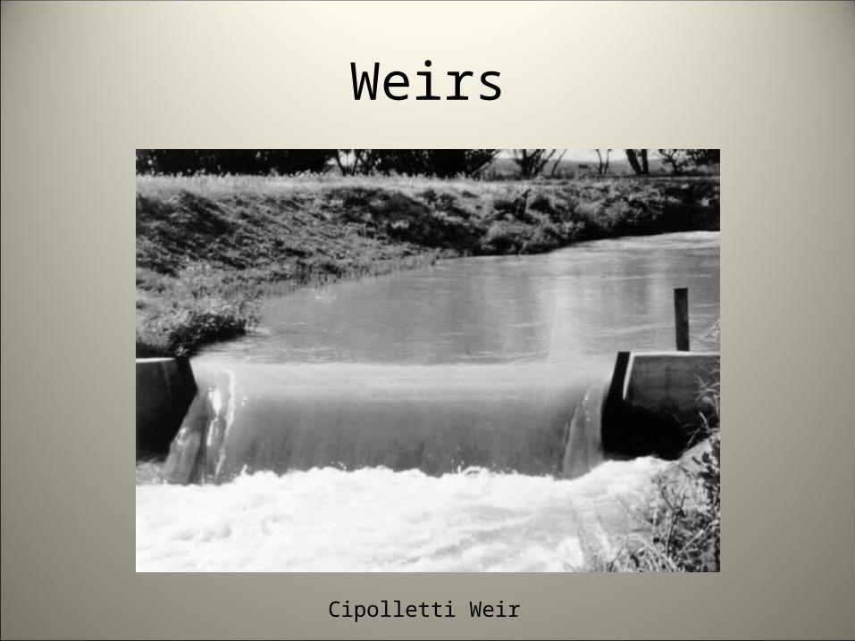
A weir is an overflow structure installed perpendicular to open channel flow
• Has a unique depth of water at an upstream measuring point for each discharge
• If the water springs clear of downstream face, acts as sharp-crested weir
• A long, raised channel control crest is a broad-crested weir
Weirs
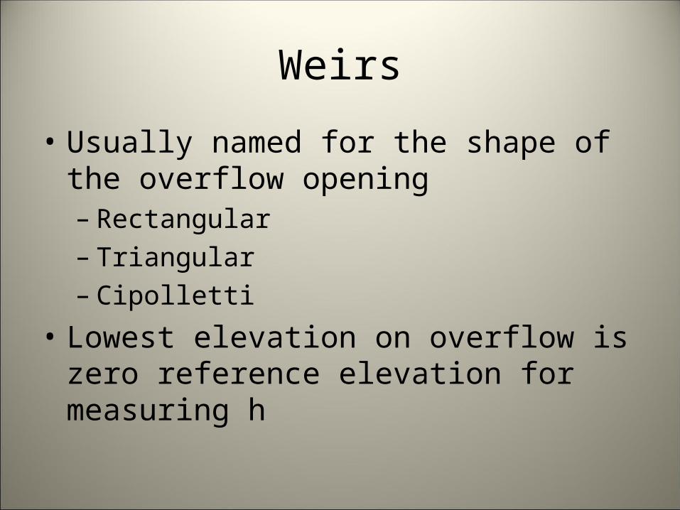
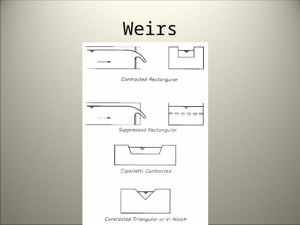
• Usually named for the shape of the overflow opening– Rectangular– Triangular– Cipolletti
• Lowest elevation on overflow is zero reference elevation for measuring h
Weirs
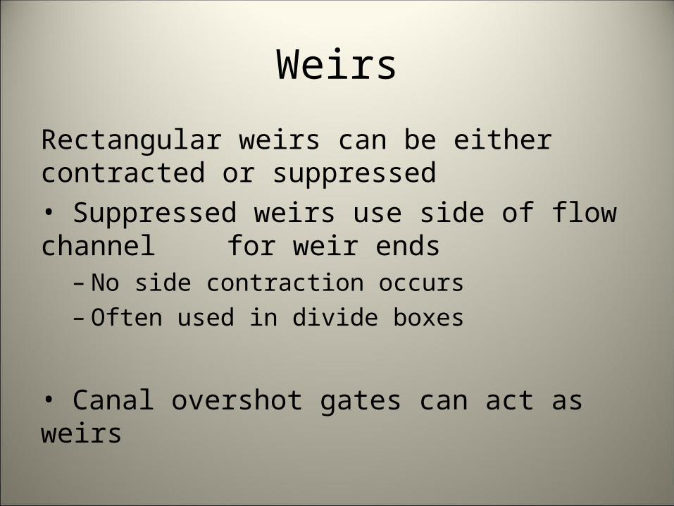
Rectangular weirs can be either contracted or suppressed• Suppressed weirs use side of flow channel for weir ends
– No side contraction occurs– Often used in divide boxes
• Canal overshot gates can act as weirs
Weirs
Weirs
Cipolletti Weir
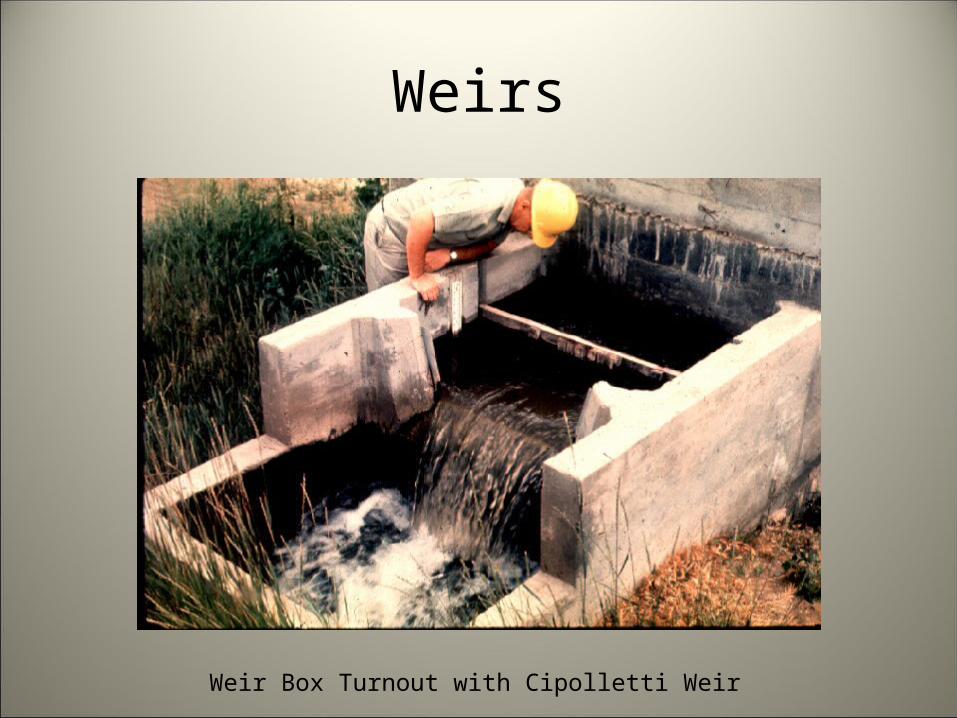
Weirs
Weir Box Turnout with Cipolletti Weir

Weirs
Compound Weir
90 degree triangular and suppressed rectangular
Weirs
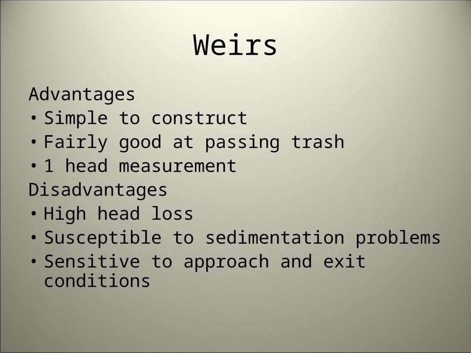
Advantages• Simple to construct• Fairly good at passing trash• 1 head measurementDisadvantages• High head loss• Susceptible to sedimentation problems• Sensitive to approach and exit conditions
Weirs
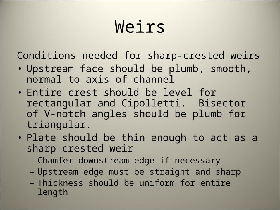
Conditions needed for sharp-crested weirs• Upstream face should be plumb, smooth, normal to
axis of channel• Entire crest should be level for rectangular and
Cipolletti. Bisector of V-notch angles should be plumb for triangular.
• Plate should be thin enough to act as a sharp-crested weir– Chamfer downstream edge if necessary– Upstream edge must be straight and sharp– Thickness should be uniform for entire length
Weirs
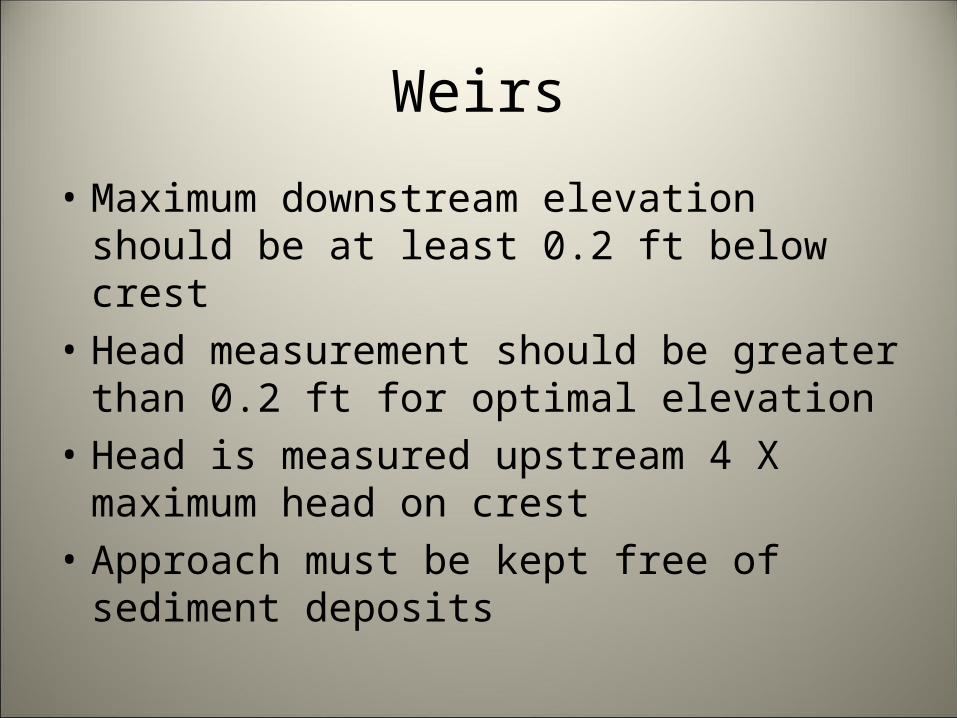
• Maximum downstream elevation should be at least 0.2 ft below crest
• Head measurement should be greater than 0.2 ft for optimal elevation
• Head is measured upstream 4 X maximum head on crest
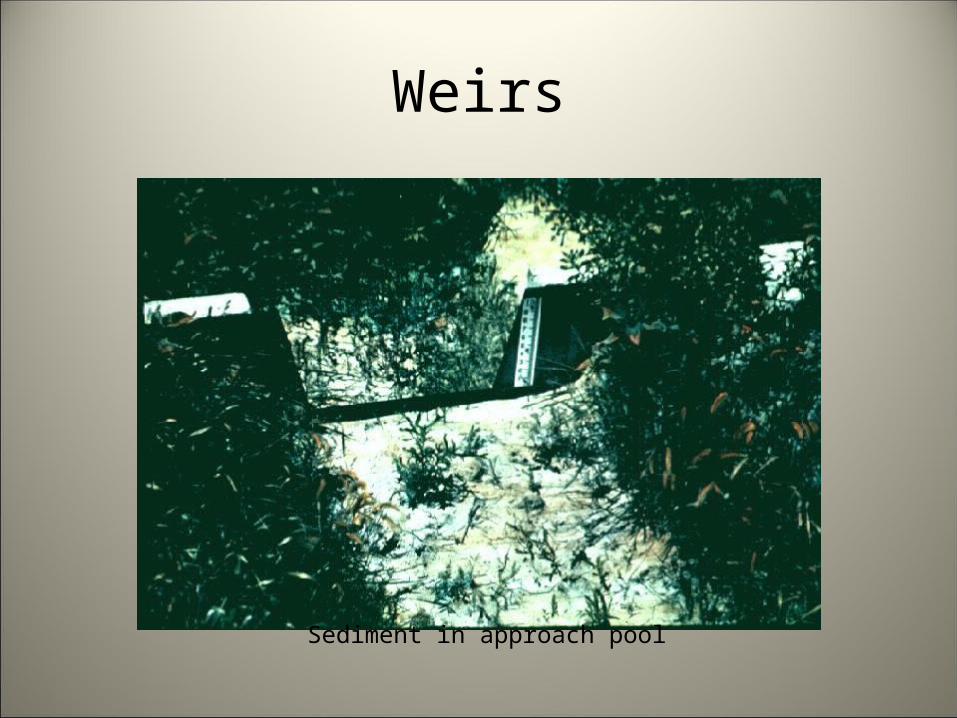
• Approach must be kept free of sediment deposits
Weirs
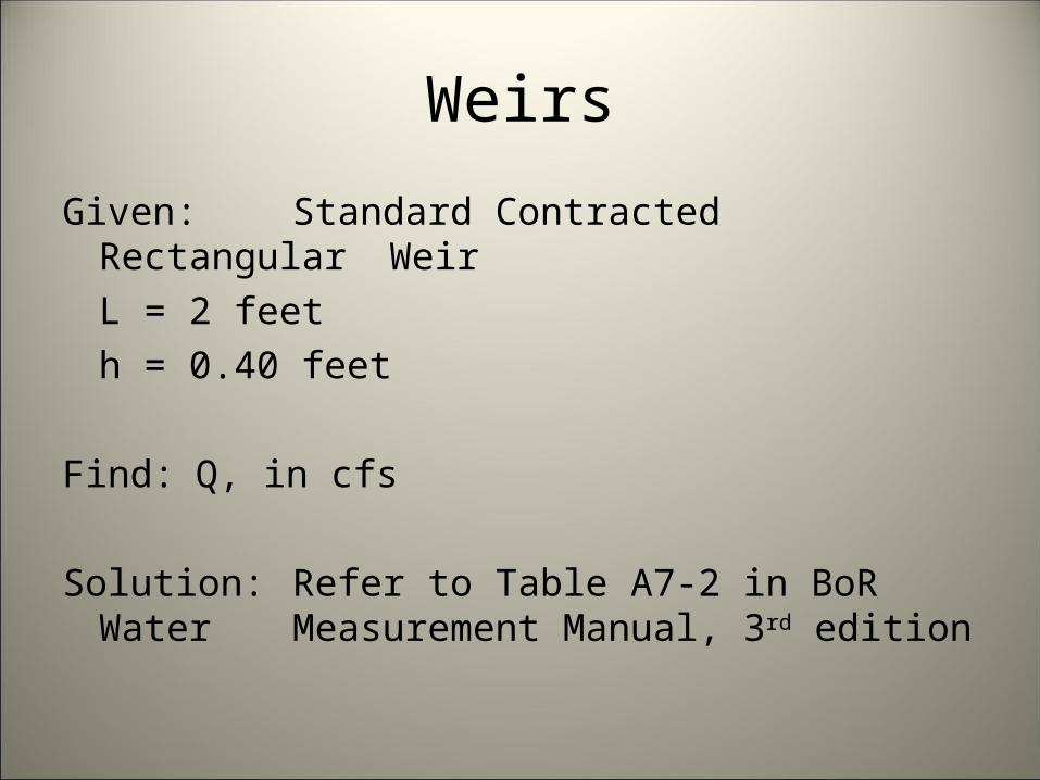
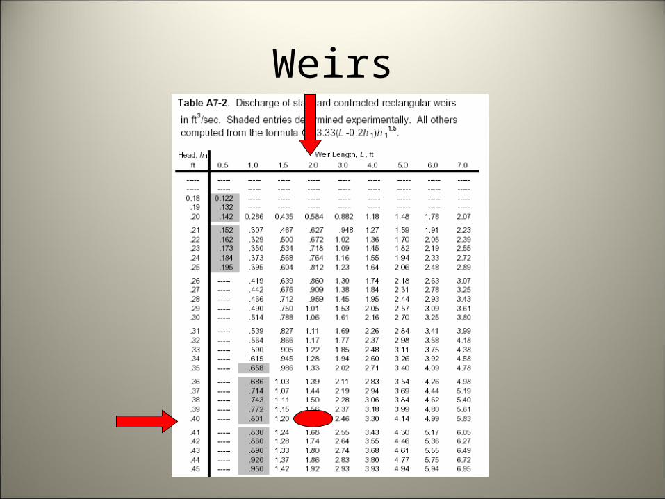
Given: Standard Contracted Rectangular Weir
L = 2 feeth = 0.40 feet
Find: Q, in cfs
Solution: Refer to Table A7-2 in BoR Water Measurement Manual, 3rd edition
Weirs
Weirs
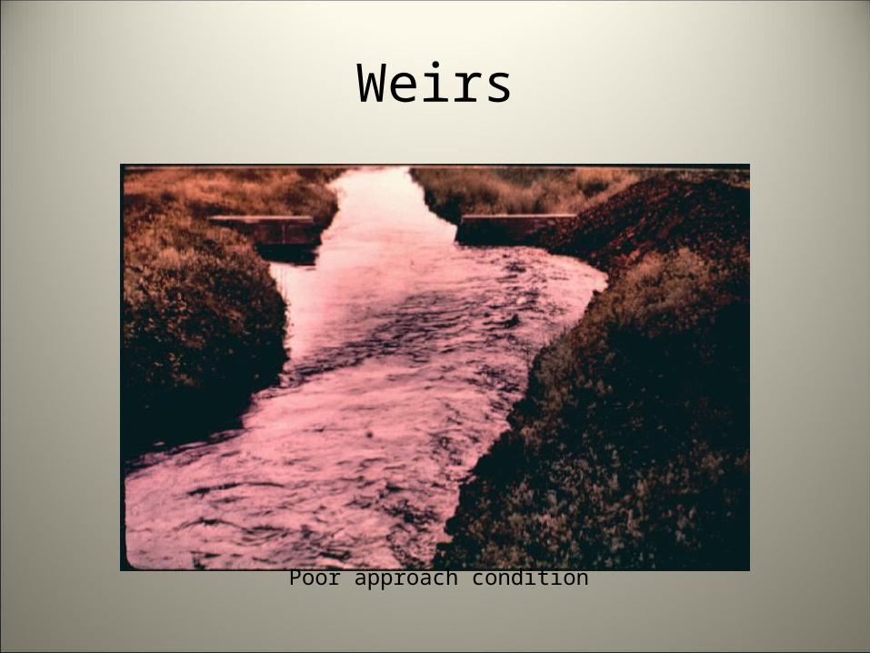
Inspection of Existing Structures• Approach flow• Turbulence• Rough water surface at staff gage• Velocity head• Exit flow conditions• Worn equipment• Poor installation
– Crest must be correctly installed
Weirs
Poor approach condition
Weirs
Sediment in approach pool
Flumes
Flumes are shaped open channel flow sections.• Force flow to accelerate
– Converging sidewalls– Raised bottom– Combination
• Force flow to pass through critical depth– Unique relationship between water surface profile
and discharge
Flumes
Two basic classes of flumes• Long throated flumes
– Parallel flow lines in control section– Accurately rate with fluid flow analysis
• Short throated flumes– Curvilinear flow in control section– Calibrated with more precise measurement
devices
Short Throated Flumes
Parshall Flume is most well-known exampleof short throated flumes• Developed by Ralph Parshall at Colorado
Agricultural College (now Colorado State University)
• ASAE Historic Landmark
Parshall FlumesSince the beginning of irrigated agriculture, it has been important to measure
flows of irrigation water. Accuracy of early water measurement methods often suffered because of trash or sediment in the water, or unusual flow
conditions. Ralph L. Parshall saw this problem when he began working for the USDA in 1915, as an irrigation research engineer. In 1922 he invented the
flume now known by his name. When this flume is placed in a channel, flow is uniquely related to the water depth. By 1953 Parshall had developed the
depth-flow relationships for flumes with throat widths from 3 inches to 50 feet. The Parshall flume has had a major influence on the equitable
distribution and proper management of irrigation water. Thousands of flumes have been used to measure irrigation water, as well as industrial and
municipal liquid flows throughout the world. This plaque marks the site of the original Colorado Agricultural College Hydraulics Laboratory, where Parshall
carried out his historic experiments. DEDICATED BY THE AMERICAN SOCIETY OF AGRICULTURAL ENGINEERS 1985
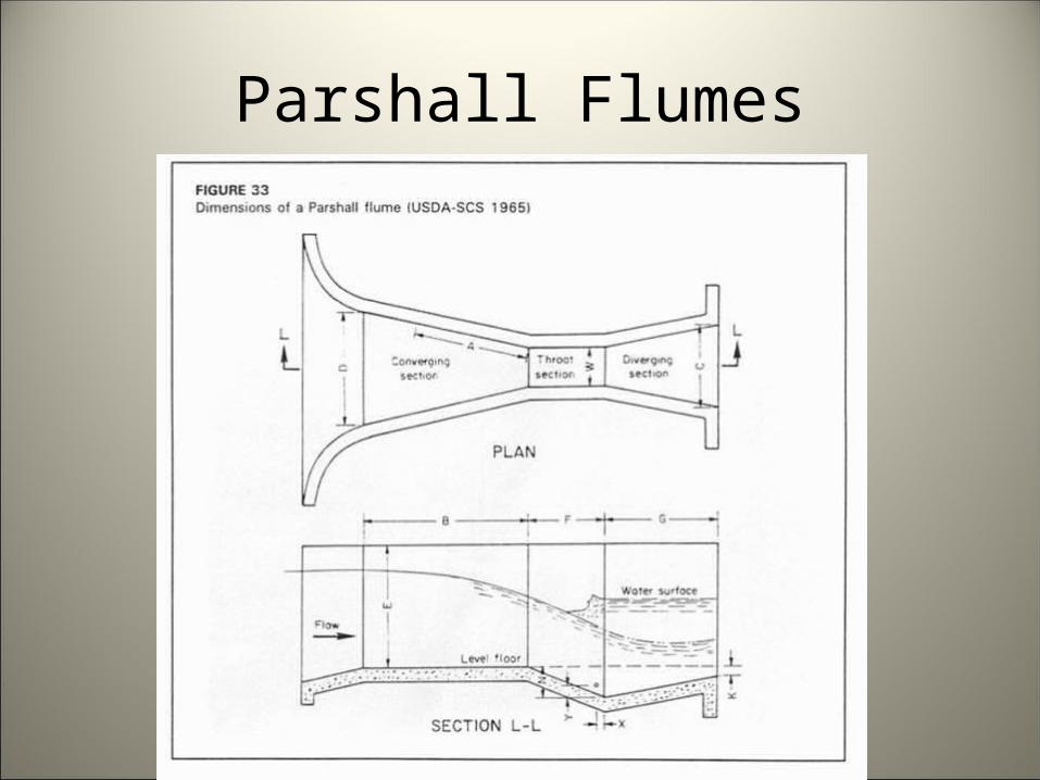
Parshall Flumes
Parshall Flumes
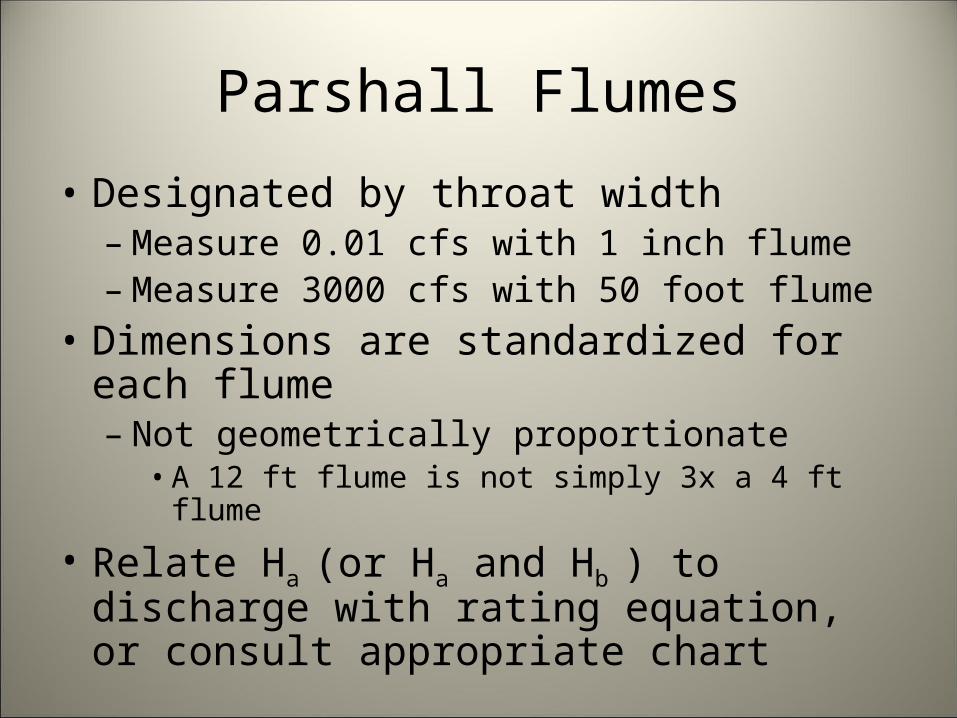
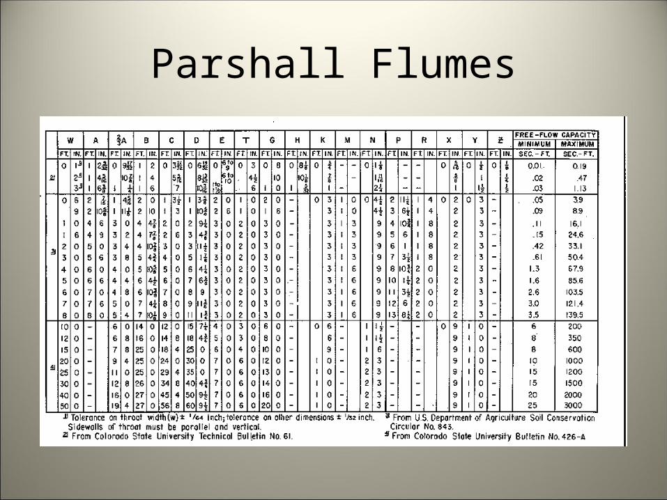
• Designated by throat width– Measure 0.01 cfs with 1 inch flume– Measure 3000 cfs with 50 foot flume
• Dimensions are standardized for each flume– Not geometrically proportionate
• A 12 ft flume is not simply 3x a 4 ft flume
• Relate Ha (or Ha and Hb ) to discharge with rating equation, or consult appropriate chart

Parshall Flumes
• Flow occurs under two conditions– Free flow
• Downstream water surface does not reduce discharge• Requires only 1 head reading (Ha)
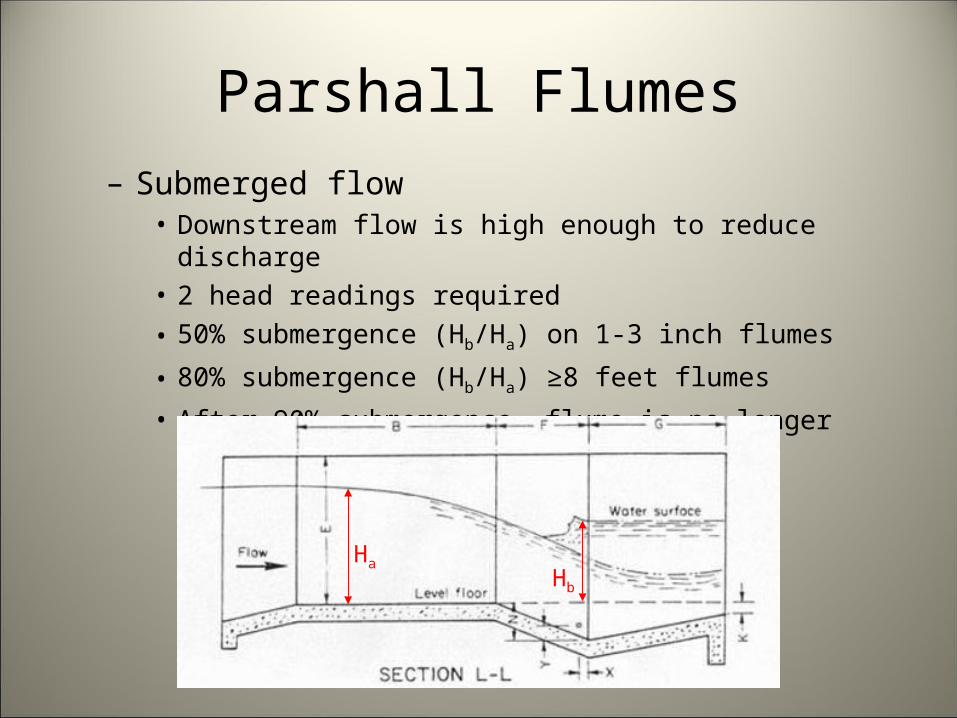
Parshall Flumes– Submerged flow
• Downstream flow is high enough to reduce discharge• 2 head readings required• 50% submergence (Hb/Ha) on 1-3 inch flumes
• 80% submergence (Hb/Ha) ≥8 feet flumes
• After 90% submergence, flume is no longer effective
HaHb
Parshall Flumes
Advantages• Relatively low head loss (1/4 of sharp crested
weir)• Handle some trash and sediment• Well accepted
– May be mandated
• Many sizes are commercially available
Parshall Flumes
Disadvantages• Complicated geometry for construction• Tight construction tolerances• Aren’t amenable to fluid flow analysis• BoR does not recommend for new
construction
Parshall Flumes
Parshall Flumes
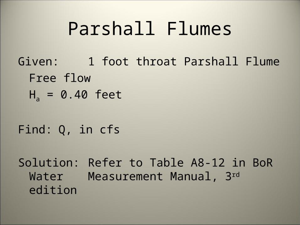
Given: 1 foot throat Parshall FlumeFree flowHa = 0.40 feet
Find: Q, in cfs
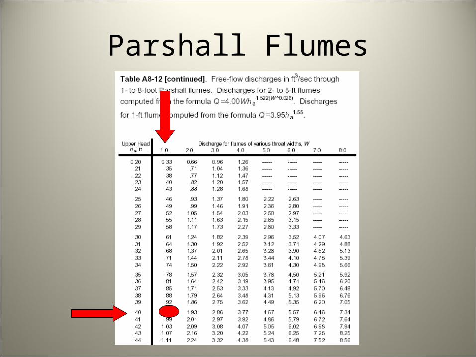
Solution: Refer to Table A8-12 in BoR Water Measurement Manual, 3rd edition
Parshall Flumes
Parshall Flumes
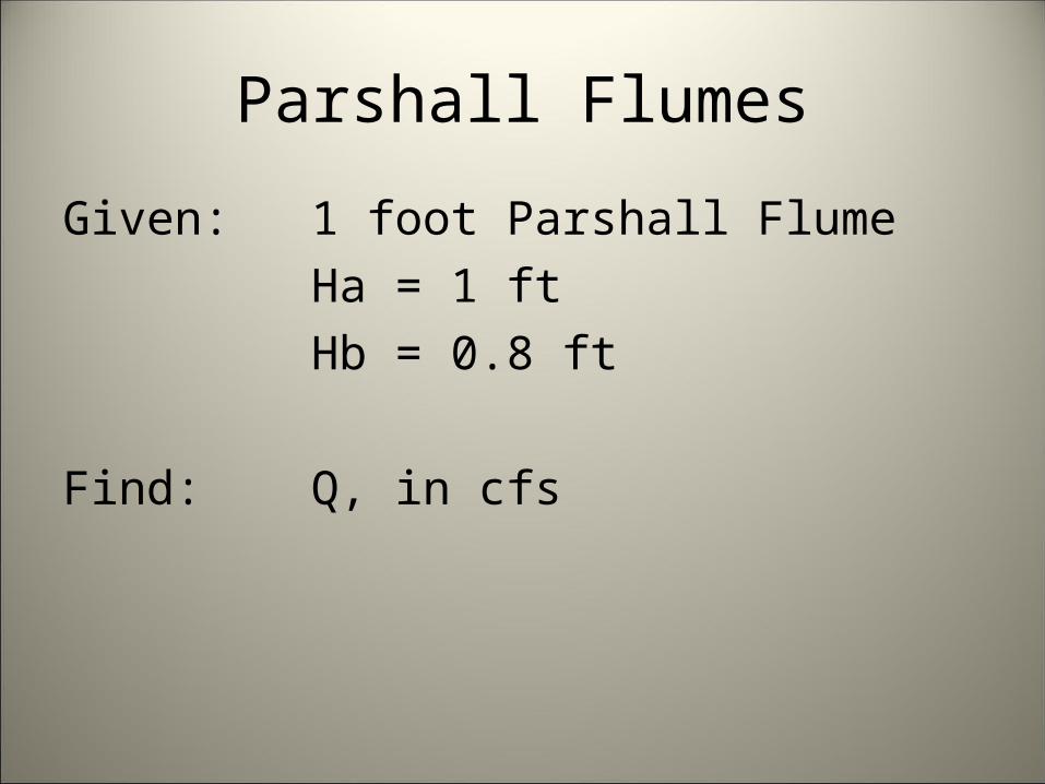
Given: 1 foot Parshall FlumeHa = 1 ftHb = 0.8 ft
Find: Q, in cfs
Parshall Flumes
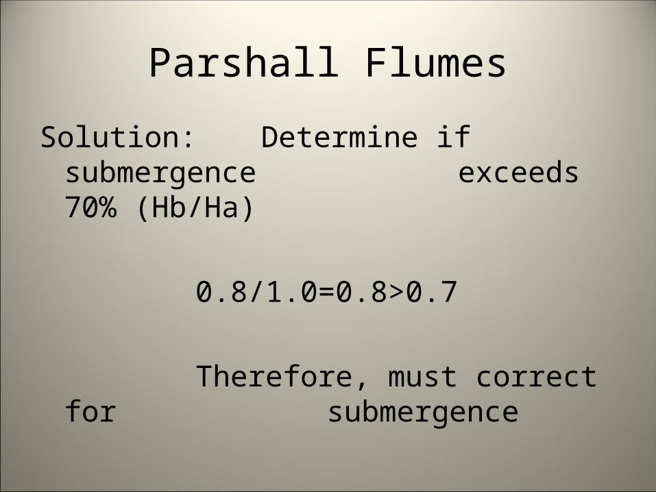
Solution: Determine if submergence exceeds 70% (Hb/Ha)
0.8/1.0=0.8>0.7
Therefore, must correct for submergence
Parshall Flumes
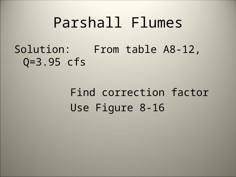
Solution: From table A8-12, Q=3.95 cfs
Find correction factorUse Figure 8-16

Parshall Flumes
Parshall Flumes
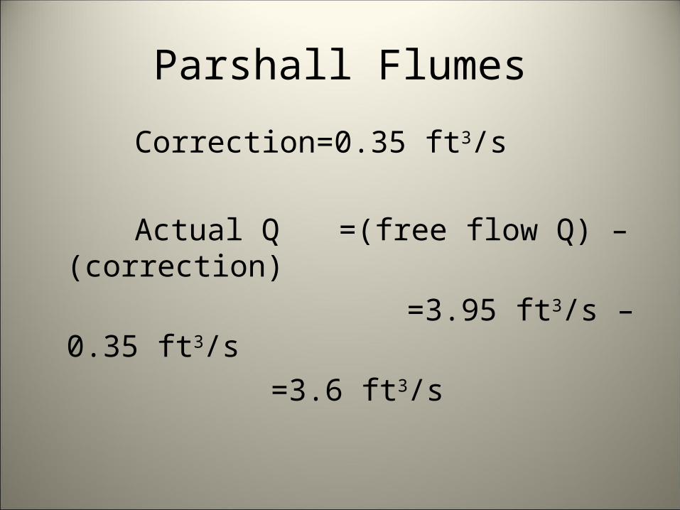
Correction=0.35 ft3/s
Actual Q =(free flow Q) – (correction) =3.95 ft3/s – 0.35 ft3/s
=3.6 ft3/s
Broad-crested Weirs
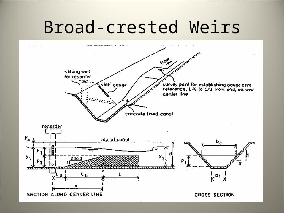
Long throated flume where only the bottom is raised. No side contractions
• Also called ramp flumes, Replogle flumes
Broad-crested Weirs
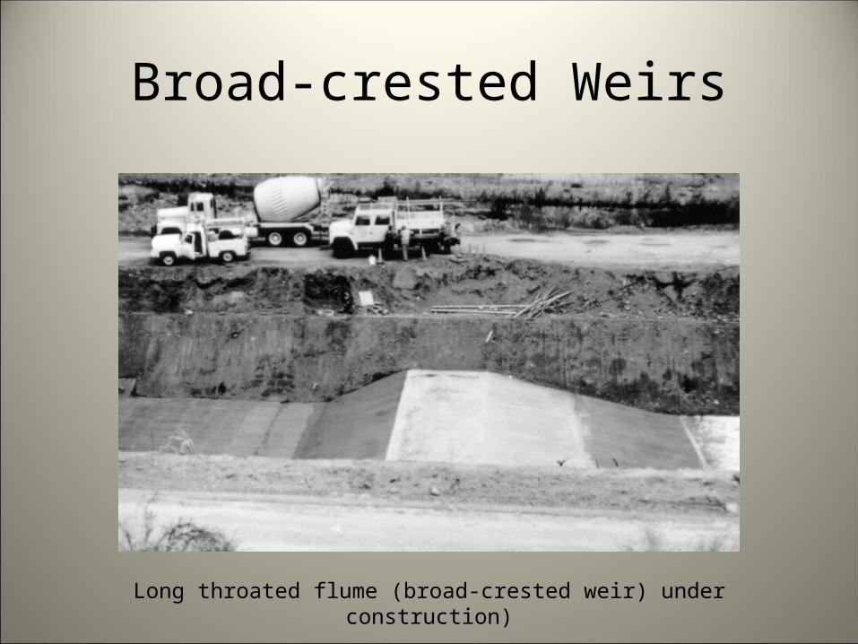
Broad-crested Weirs
Long throated flume (broad-crested weir) under construction)
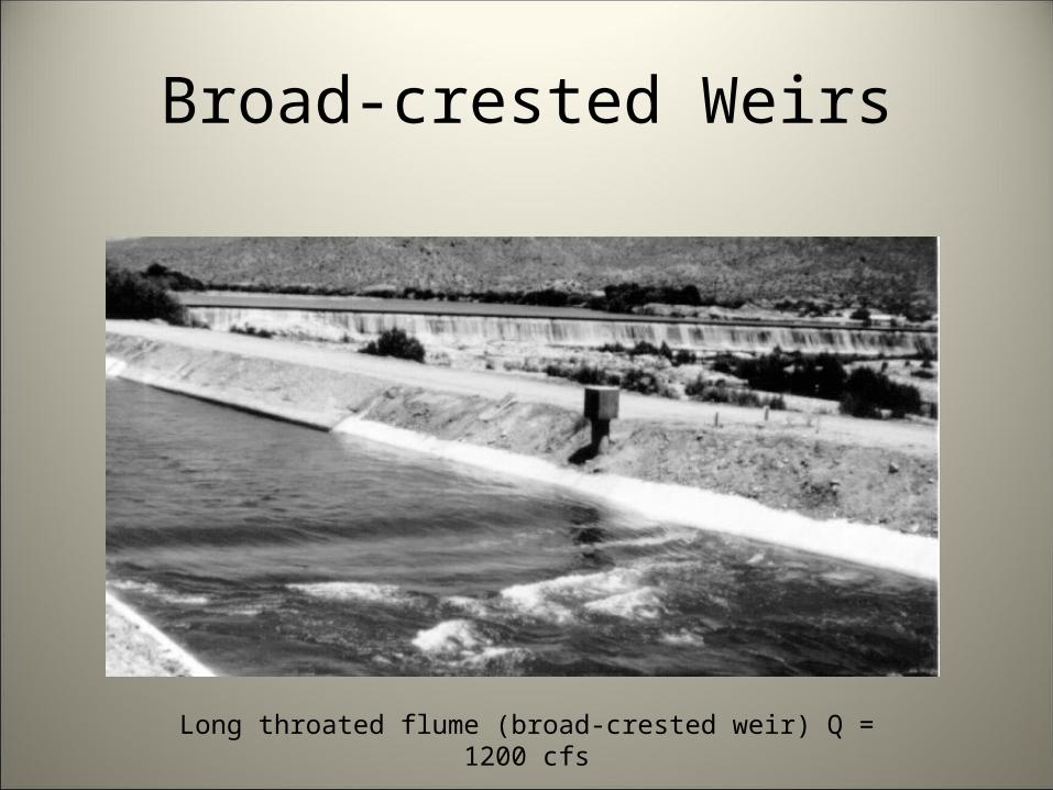
Broad-crested Weirs
Long throated flume (broad-crested weir) Q = 1200 cfs

Broad-crested Weirs
Advantages• Easily constructed, especially in existing
concrete lined channels• WinFlume software available to quickly design
and rate structures• Less expensive construction• Low head loss• Handle trash and sediment well
Broad-crested Weirs
Disadvantages• Some state laws or compacts may preclude
use• Not readily accepted by some water users
– Not what they’re used to using
Other Flumes
Several other types of flumes are used• H-flumes• Cutthroat flumes• Palmer-Bowles

Other Flumes
FlumesInspection of Existing Structures• Approach flow
– Flumes are in-line structures– Should have smooth flow across width and depth of cross
section– Length of straight approach varies depending on control
width, channel width, and velocity• Turbulence• Level both along and perpendicular to flow• Excessive submergence• Exit flow conditions
Submerged Orifices
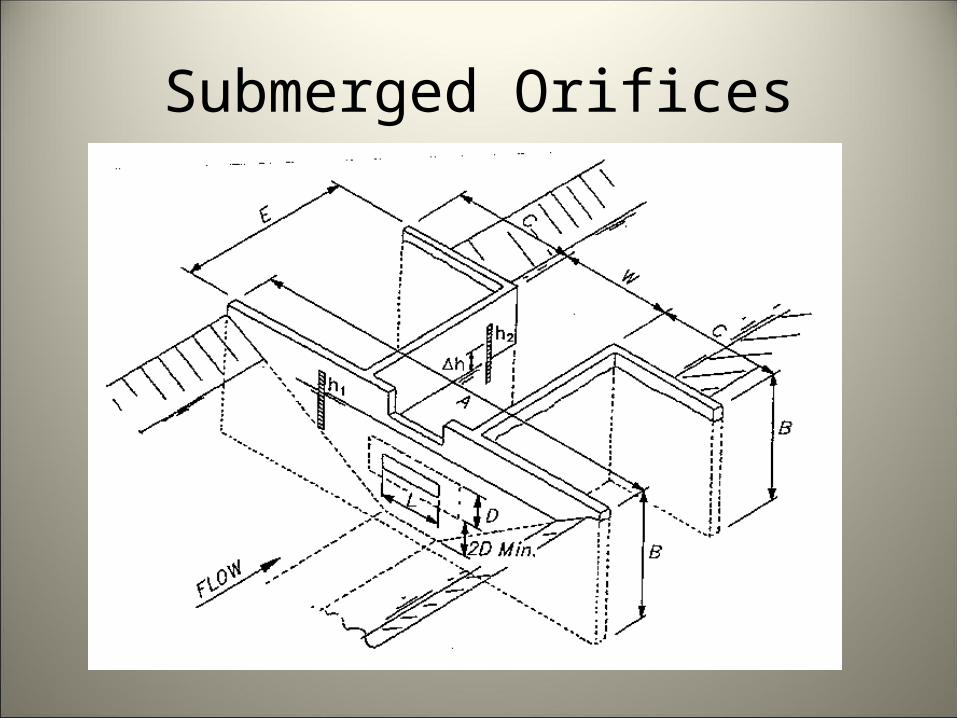
A well defined sharp-edged opening in a wall or bulkhead through which flow occurs• When size and shape of the orifice and the
heads acting on it are known, flow measurement is possible
• Orifices are typically circular or rectangular in shape
• Can be used to regulate and measure water in a turnout structure
• Radial gates can act as submerged orifices
Submerged Orifices
Submerged Orifices
Advantages• Less head required than for weirs• Used where space limitations prevent weir or
flumeDisadvantages• Sediment and debris accumulation will
prevent accurate measuring• Typically not used if conditions permit flumes
which handle trash better
Current Meters
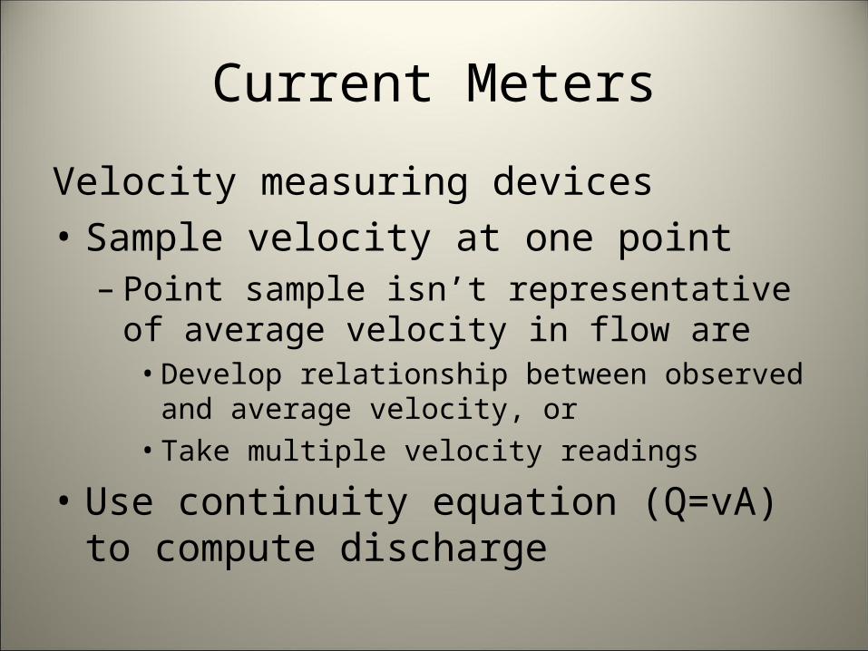
Velocity measuring devices• Sample velocity at one point
– Point sample isn’t representative of average velocity in flow are
• Develop relationship between observed and average velocity, or
• Take multiple velocity readings
• Use continuity equation (Q=vA) to compute discharge
Current Meters
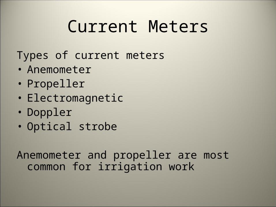
Types of current meters• Anemometer• Propeller• Electromagnetic• Doppler• Optical strobe
Anemometer and propeller are most common for irrigation work
Current Meters
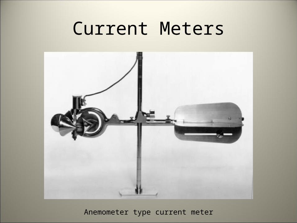
Anemometer type current meter
Other Open Channel Methods
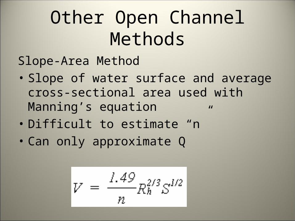
Slope-Area Method• Slope of water surface and average cross-
sectional area used with Manning’s equation• Difficult to estimate “n”• Can only approximate Q
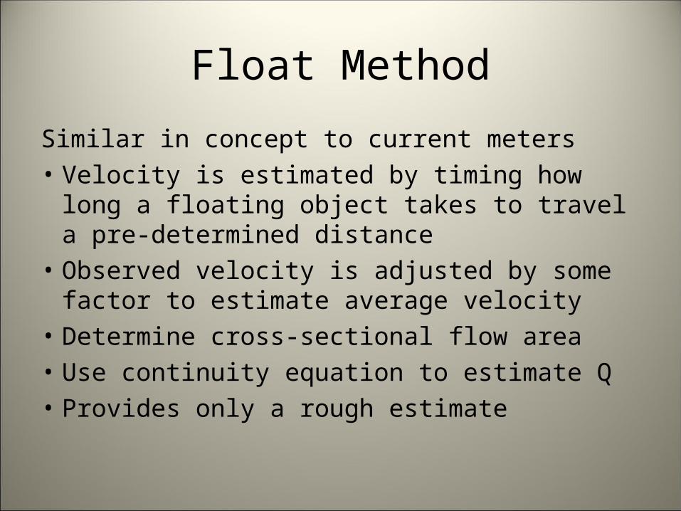
Float Method
Similar in concept to current meters• Velocity is estimated by timing how long a
floating object takes to travel a pre-determined distance
• Observed velocity is adjusted by some factor to estimate average velocity
• Determine cross-sectional flow area• Use continuity equation to estimate Q• Provides only a rough estimate
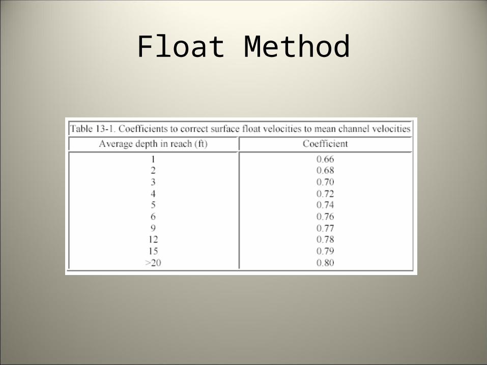
Float Method
Pressurized Conduit Devices
Pipeline devices are usually classified by their basic operation• Calibrated velocity sensing meters • Differential head meters• Positive volume displacement summing
meters (municipal water)• Measured proportional or calibrated
bypass meters• Acoustic meters
Differential Head Meters
Include venturi, nozzle, and orifice meters• When properly installed, accuracy ±1%
– Some irrigation operating conditions probably limit accuracy to ±3-5%
• No moving parts– Uses principle of accelerating flow through a constriction– Resulting pressure difference is related to discharge using
tables or curves, or a suitable coefficient and the proper equation
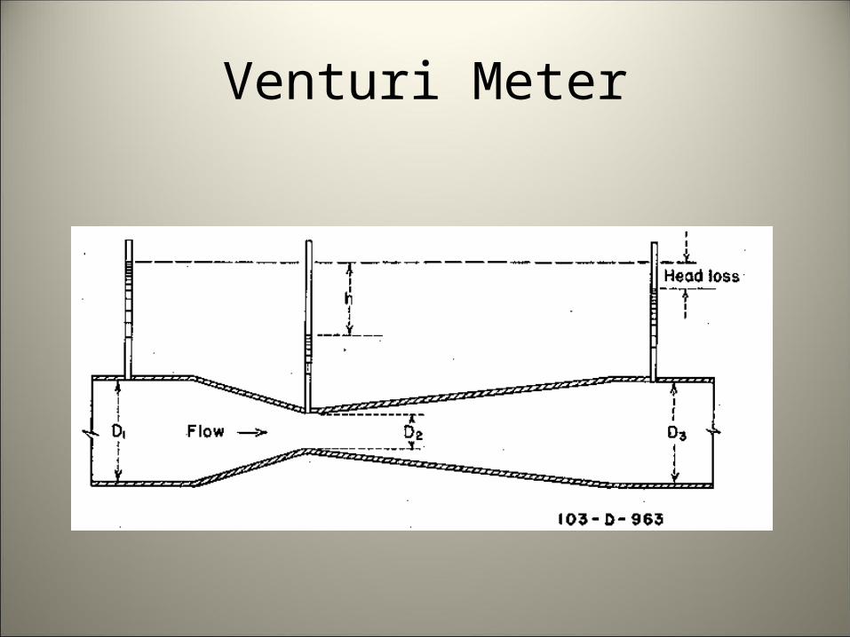
Venturi Meter
Common differential head meter• Minimal head loss• Full pipe flow required• Also used to inject chemicals into an irrigation
system– Pressure reduction is used to pull chemicals into
the system• Examples of venturi meters constructed of
standard plastic pipe fittings
Venturi Meter

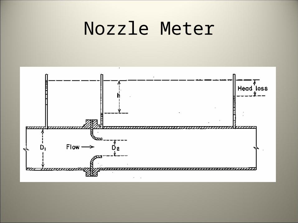
Nozzle Meter
Simplified form of venturi meter• Gradual downstream expansion of venturi is
eliminated• Higher head loss than venturi• Full pipe flow required• Not used extensively in irrigation
Nozzle Meter
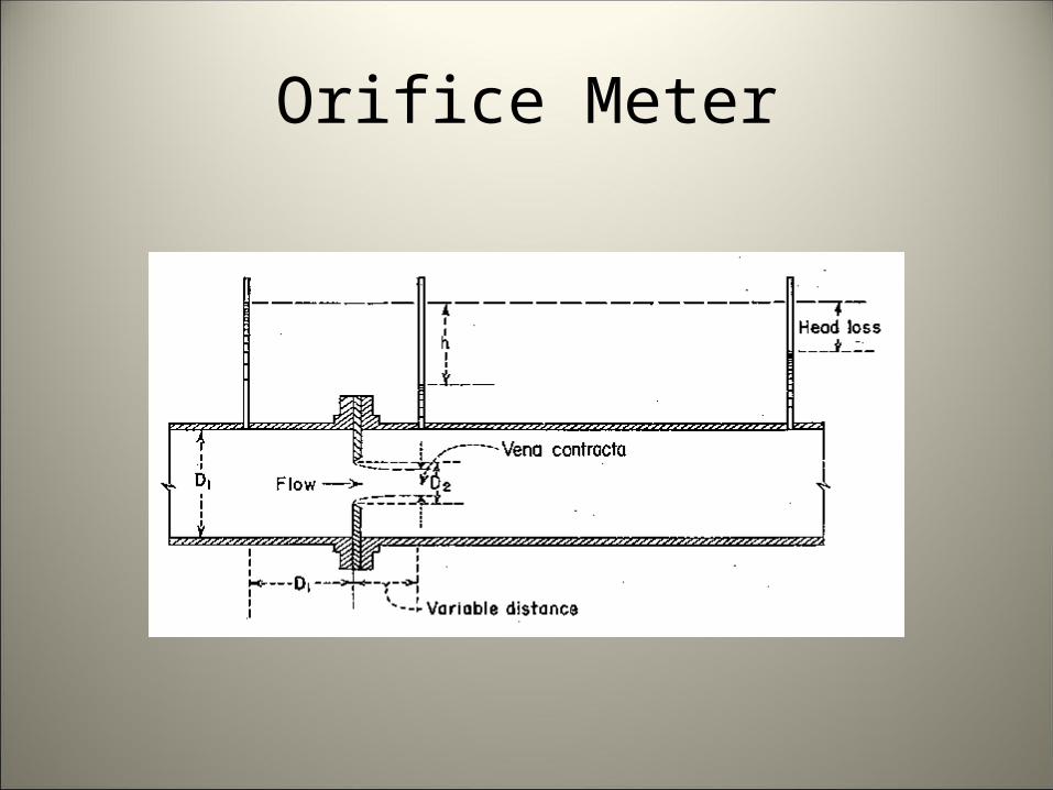
Orifice Meter
Another differential pressure meter• Often used for measuring well discharge• Also used to measure chemical injections
– Typically small meters with details provided by manufacturer
• Requires long straight pipe lengths• Full pipe flow required• Limited discharge ratio
Orifice Meter
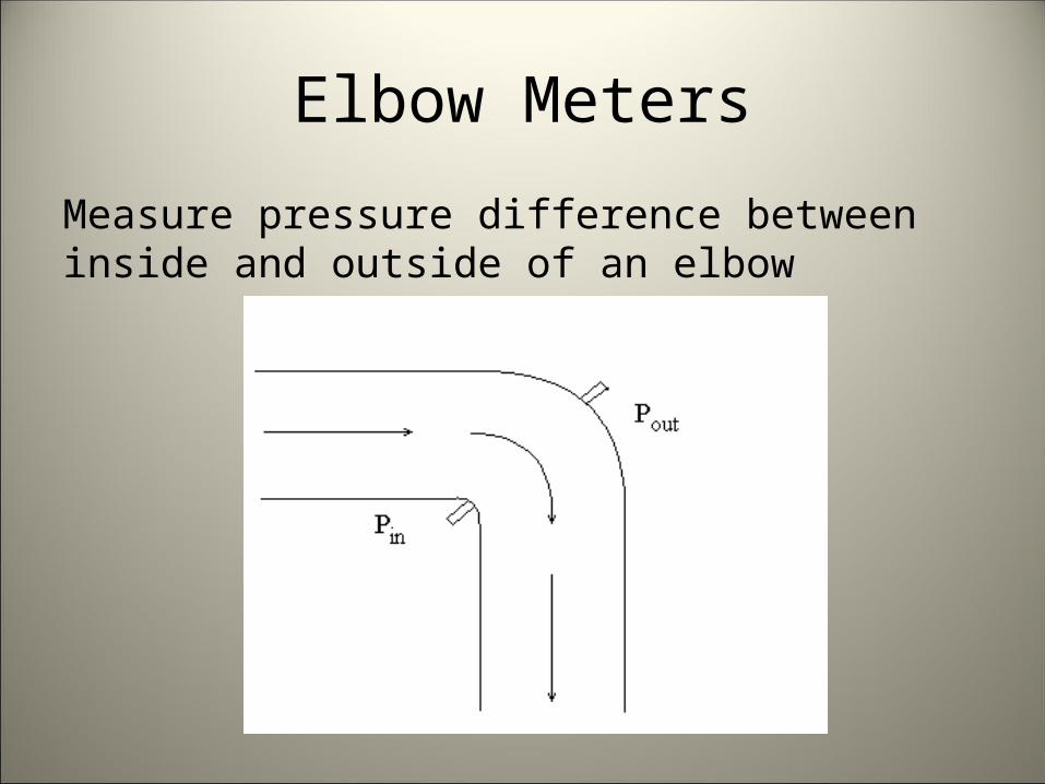
Elbow Meters
Measure pressure difference between inside and outside of an elbow
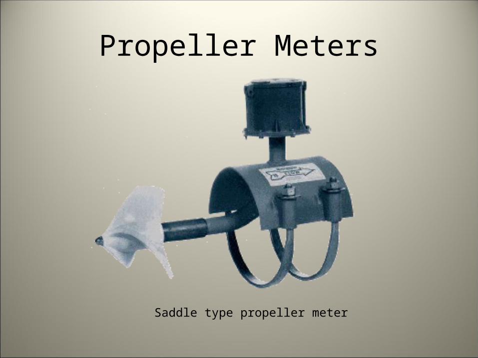
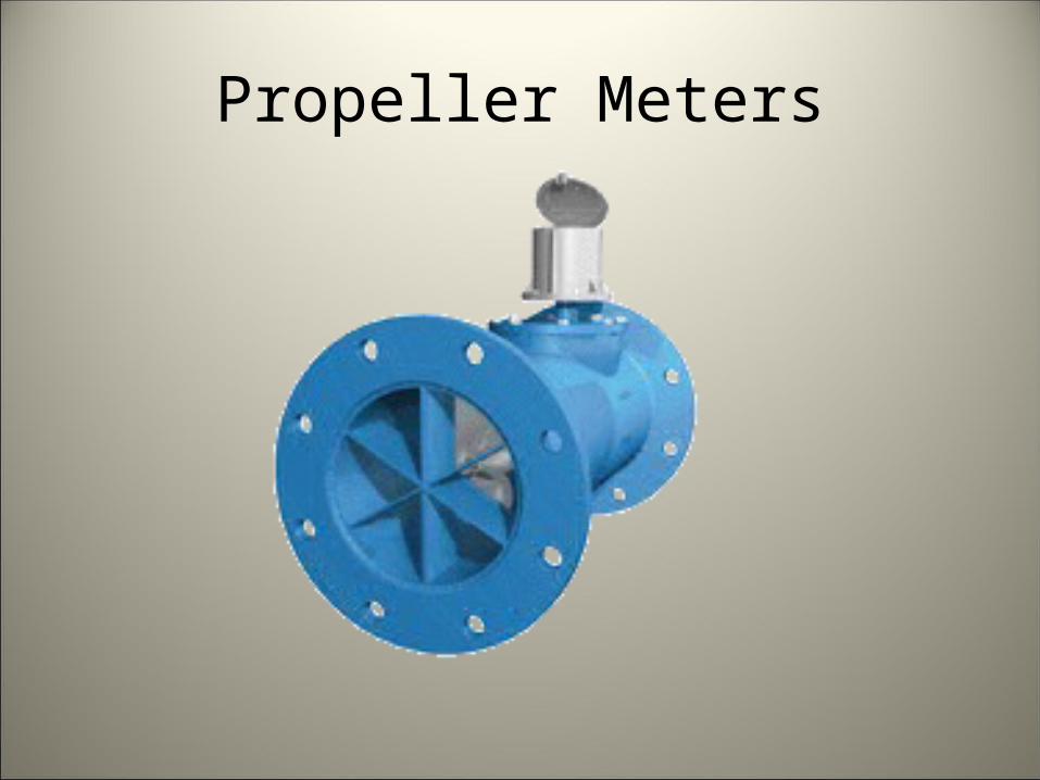
Propeller Meters
Used at end of pipes and in conduits flowing full
• Multiple blades that rotate on horizontal axle
• Must have full pipe flow
• Basically operate on Q=vA principle
• Usually have totalizer plus instantaneous discharge display
• Accuracy can be ±2-5% of actual flow
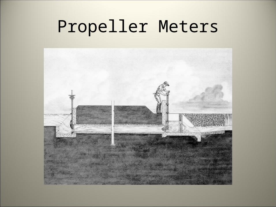
Propeller Meters
Propeller Meters
Saddle type propeller meter
Propeller Meters
Propeller Meters
• Should be selected to operate near middle of design discharge range– If system has oversized pipes, some sections may
need replaced with smaller pipes to provide correct velocity and approach
• Must be installed to manufacturer’s specifications for accurate measurement
• Must have full pipe flow
Propeller Meters
Advantages• Commercially available• Totalizing meter• Can achieve good accuracy
Propeller Meters
Disadvantages• Operating conditions different from
manufacturer’s calibration conditions will affect accuracy
• Only tolerate small amount of weeds and debris
• Moving parts operating underwater• Can require a good deal of maintenance and
inspection
Other Conduit Devices
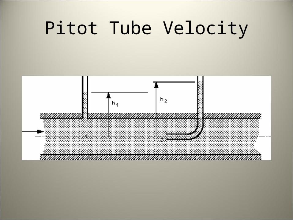
Pitot Tube Velocity Measurements• Piezometer
– Straight tube attached flush to wall and perpendicular– Senses pressure head in pipe
• Pitot Tube– Right angle bend inserted with horizontal leg pointed
upstream and parallel to flow– Senses both velocity and pressure head
• Velocity head, flow area, and coefficient can then be used to calculate flow rate
Pitot Tube Velocity
Other Conduit Devices• Magnetic Flowmeters
– Use the principle that voltage is induced in an electrical conductor moving through a magnetic field. Conductor is flowing water
– For a given field strength, the magnitude of the induced voltage is proportional to velocity
• Deflection Meters– Vane or plate projecting into flow and a sensing element
to measure deflection– Calibrated to indicate flow in desired units
• Vortex Flowmeters– Obstructions in flow generate vortex shedding trails
• Properly shaped obstructions create vortices that can be sensed and related to velocity
Other Conduit Methods
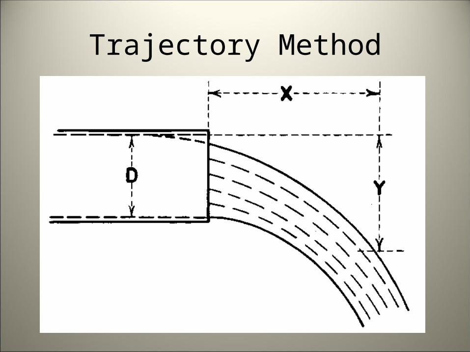
Trajectory Method• Measure the horizontal and vertical
coordinates of a point in the jet of water issuing from the end of a pipe
• Accurate ±15%• Coordinates can be difficult to accurately
measure
Trajectory Method
• Vertical Pipe• Two kinds of flow occur, depending on how high water
rises– <0.37d, circular weir– Transistional region between– >1.4d, jet flow
• Horizontal Pipe– Pipe must be truly horizontal; slope will skew
results• Vertical component can be difficult to measure
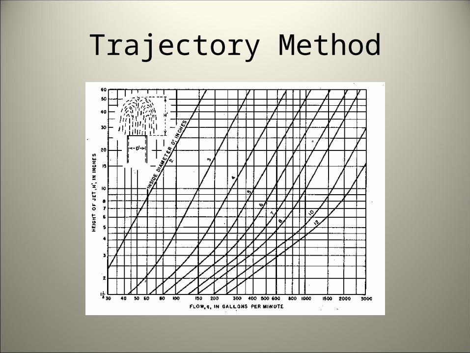
Trajectory Method
Trajectory Method
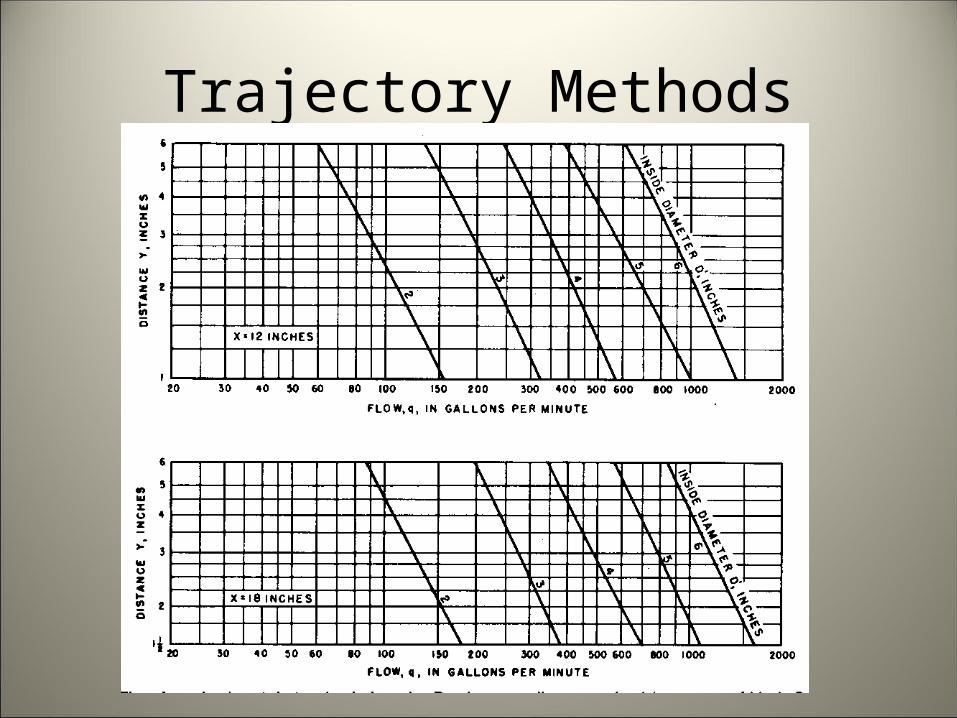
Trajectory Methods
Other Conduit Methods
Power Consumption Coefficients• Volume discharged from wells can be estimated
using power consumption records– Wells must be analyzed to determine the energy needed
to pump a certain volume of water– Relationship can then be used to estimate discharge
volume– Only certified well testers can perform the tests and
develop the power consumption coefficient– Must recalibrate every 4 years, or more often depending
on conditions
Other Conduit Methods
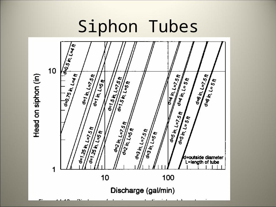
Siphon Tubes• Estimate discharge based on head, diameter,
and length of siphon tubes• Accuracy ±10-15%• Provides an in-field method of estimating flow• Information also available in irrigator’s guides
and NRCS Engineering Field Manual, Chapter 15
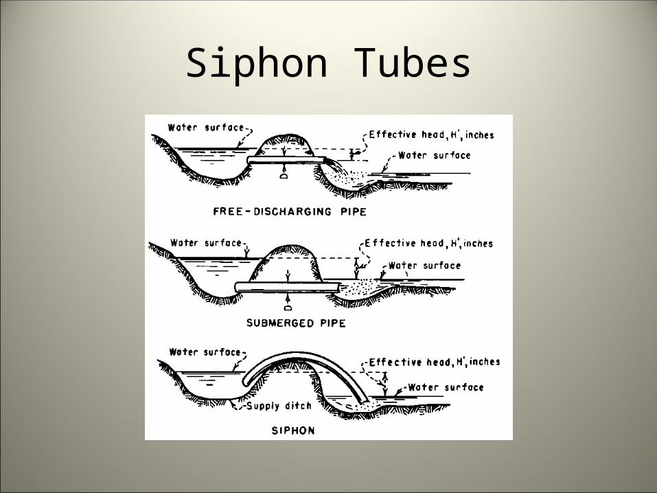
Siphon Tubes
Siphon Tubes
Summary
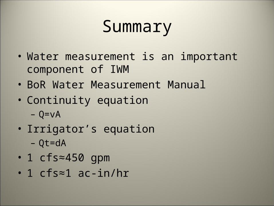
• Water measurement is an important component of IWM
• BoR Water Measurement Manual• Continuity equation
– Q=vA
• Irrigator’s equation– Qt=dA
• 1 cfs≈450 gpm• 1 cfs≈1 ac-in/hr
Summary
• Open channel devices– Flumes– Weirs– Submerged orifices
• Pressurized conduit devices– Propeller meters– Differential head meters
Summary
• Installation requirements– Examine existing structures
• Other opportunities for measurement– Canal gates– Float method– Power consumption coefficient– Pipe trajectory– Siphon tubes

Questions?