water management and waste water … the purpose of this ... interactions in solar aquatic systems...
TRANSCRIPT

WATER MANAGEMENT AND WASTE WATER TREATMENT AT THE UNIVERSITY OFBRITISH COLUMBIA: A STUDY FOR SUSTAINABLE ALTERNATIVES
by
Michael GrantGeoff Hill
Caila HolbrookPeter LymburnerAlison McTavish
Anna Sundby
AN UNDERGRADUATE HONOURS THESIS SUBMITTED IN PARTIALFULFILMENT OF THE REQUIREMENTS FOR THE DEGREE OF
BACHELOR OF SCIENCE
in
ENVIRONMENTAL SCIENCE
THE UNIVERSITY OF BRITISH COLUMBIAApril 2002

ii
Abstract
The purpose of this study was to determine whether or not alternative water management optionscould be applied to the University of British Columbia to maximize sustainability, researchopportunities, and the degree of independence from the Greater Vancouver Regional District(GVRD) while being legally, logistically and financially reasonable. The main focus was onthree aspects of water management: stormwater management, rooftop rainwater harvesting, andwastewater treatment. The stormwater management section attempts to evaluate the importanceof numerous small detention ponds on water quality and erosion potential. A pilot project wasdeveloped to test some management options, but due to time and seasonal constraints final datacould not be collected and conclusions could not be made. Rooftop rainwater harvestingevaluated the harvesting potential that UBC has and if this potential would be significant enoughto make a difference to the overall water consumption on campus. It was determined that arelatively small amount of water could be collected, but that small amount could potentially saveUBC money, decrease the demand on GVRD water, and create water reserves for times ofemergency. Wastewater treatment was evaluated on the basis of using solar aquatics andconventional treatment methods to process UBC’s wastewater and possibilities to reuse thetreated effluent and sludge. After studying and evaluating the systems used in multiple casestudies, a hybrid system was proposed. This was based upon the importance of plant-microbeinteractions in solar aquatic systems and the cost effectiveness of conventional treatment. It wasdetermined that potential exists for the reuse of effluent and sludge in experimental applicationsin agriculture, aquaculture, domestic and industrial settings. Overall, the options considered andevaluated in the thesis indicated that the University of British Columbia can implement theseoptions to increase sustainability, research opportunities, and independence from the GreaterVancouver Regional District while being legally, logistically, and financially practical.

iii
Table Of Contents
ABSTRACT .............................................................................................................................II
TABLE OF CONTENTS....................................................................................................... III
LIST OF TABLES ................................................................................................................ VII
LIST OF FIGURES .............................................................................................................VIII
PREFACE .............................................................................................................................. IX
ACKNOWLEDGMENTS .......................................................................................................X
CHAPTER 1 - INTRODUCTION AND OVERVIEW......................................................1
1.1 INTRODUCTION.............................................................................................................11.2 RESEARCH OBJECTIVE..................................................................................................31.3 METHODS ....................................................................................................................4
CHAPTER 2 - UNIVERSITY OF BRITISH COLUMBIA BACKGROUND .................5
2.1 UBC COMMUNITY .......................................................................................................52.2 CURRENT STATE...........................................................................................................52.3 CURRENT WATER BALANCE .......................................................................................10
CHAPTER 3 - STORMWATER MANAGEMENT OPTIONS......................................12
3.1 STORMWATER SYSTEM...............................................................................................12I. Stormwater Impacts And Management ...........................................................................12
a. Introduction / History.............................................................................................12b. Urbanization ..........................................................................................................13
i Hydrology..........................................................................................................13ii Stream Channel Morphology .............................................................................14iii Habitat...............................................................................................................14iv Water Quality ....................................................................................................14
II. Lower Fraser Valley .....................................................................................................15a. Summary Of Stormwater Impacts Upon Water Bodies...........................................15
i Hydrology..........................................................................................................15ii Stream Channel Morphology .............................................................................16iii Habitat...............................................................................................................16iv Water Quality ....................................................................................................16
b. GVRD BMP Guide To Stormwater Treatment.......................................................17III. University Of British Columbia ...................................................................................17
a. Current State..........................................................................................................17b. Stormwater Treatment Options ..............................................................................20
IV. UBC Temporary Detention Pond Pilot Project ............................................................24a. Objective ...............................................................................................................24b. Methodology .........................................................................................................25

iv
i Location.............................................................................................................25ii Design ...............................................................................................................25iii Results ...............................................................................................................31
3.2 RAINWATER HARVESTING ..........................................................................................33I. Background....................................................................................................................33II. Main Proposal ..............................................................................................................37III. Rainwater Rooftop Collection......................................................................................37IV. Filtration .....................................................................................................................39
a. Slow Sand Filtration ..............................................................................................39b. Chlorination...........................................................................................................40c. Chlorine Dioxide ...................................................................................................41d. Ozone ....................................................................................................................41e. Ultraviolet Light (UV)...........................................................................................42
V. Water Application Options............................................................................................43VI. Storage And Distribution .............................................................................................44VII. Brief Summary............................................................................................................46
CHAPTER 4 - WASTEWATER MANAGEMENT OPTIONS......................................47
4.1 BACKGROUND TO UBC SEWAGE AND CURRENT TREATMENT.....................................47I. UBC Sanitary Piping System..........................................................................................47II. Iona Island Wastewater Treatment Plant ......................................................................49
4.2 THE ROLE OF AQUATIC PLANTS IN WASTEWATER TREATMENT ..................................50I. Introduction ...................................................................................................................50II. Floating Aquatic Macrophytes......................................................................................51III. Emergent Aquatic Macrophytes ...................................................................................53IV. Removal of N, P, BOD, TSS, And Pathogens................................................................53
4.3 WASTEWATER TREATMENT OPTIONS ..........................................................................56I. Wetlands And Lagoons...................................................................................................56II. Plant-Microbial Filters.................................................................................................56III. Solar Aquatics Overview .............................................................................................57
a. Primary Settling Tanks ..........................................................................................58b. Blending Tanks......................................................................................................59c. Solar Aquatic Aerated Tanks .................................................................................59d. Extended Aeration, Activated Sludge Reactors ......................................................60e. Clarifiers................................................................................................................61f. Ecological Fluidized Bed (EFB) ............................................................................61
4.4 CASE STUDIES............................................................................................................63I. Case Study Evaluation ...................................................................................................63
a. Questions Considered ............................................................................................63b. Bear River Solar Aquatics Wastewater Treatment Facility .....................................63c. Beausoleil Solar Aquatic Water Reclamation Site..................................................65d. Cannon Beach: Wooded Wetlands For Wastewater Treatment...............................66e. CK Choi Building, UBC: Grey Water Trench ........................................................67f. Modular Peat Bed Wastewater Treatment System: Greely, Ontario........................68g. Waterloo Biofilter Systems Inc.: Prince Albert, Saskatchewan...............................69h. Advanced Ecological Engineering System (AEES) “Living Machine”...................71
4.5 POST TREATMENT FOR UBC.......................................................................................73

v
4.6 APPLICATIONS OF WATER REUSE................................................................................74I. Proposed Reuse Applications at UBC ............................................................................75II. Water Quality Issues And Monitoring ...........................................................................77III. Other Reuse Applications ............................................................................................79
a. Agriculture ............................................................................................................79b. Aquaculture ...........................................................................................................81c. Reuse Applications Of Sludge ...............................................................................83
4.7 APPLICATIONS FOR UBC............................................................................................84I. Pilot Scale Wastewater Treatment Plant ........................................................................84
a. Disclaimer .............................................................................................................85b. System Overview...................................................................................................85c. Anaerobic Reactor .................................................................................................86d. Activated Sludge Extended Aeration Reactor.........................................................87e. Clarifier .................................................................................................................88f. Solar Aquatics / Biomedia Aerated Tanks..............................................................88g. Ecological Fluidized Bed (EFB) ............................................................................89h. Anoxic Denitrifying Media Tank ...........................................................................89i. Sub-surface Wetland..............................................................................................90j. Conclusion.............................................................................................................91k. Costs Of The Pilot Plant ........................................................................................92
II. Full Scale Treatment Plant ...........................................................................................92
CHAPTER 5 - SYNTHESIS OF STORMWATER AND WASTEWATER ..................93
5.1 SUMMARY OF PROPOSED SYSTEM ..............................................................................935.2 PROPOSED WATER BALANCE......................................................................................935.3 MULTIPLE ACCOUNT ANALYSIS..................................................................................95
I. Introduction ...................................................................................................................95II. The Financial Account..................................................................................................96III. The Social and Environmental Accounts....................................................................101IV. Results and Conclusion..............................................................................................103
CHAPTER 6 - CONCLUSION AND FUTURE RECOMMENDATIONS ..................105
6.1 CONCLUSION............................................................................................................1056.2 FUTURE DIRECTION..................................................................................................106
I. Stormwater Future .......................................................................................................106II. Rain Harvesting..........................................................................................................107III. Wastewater Treatment At UBC..................................................................................108IV. Environmentally Sound Initiatives .............................................................................108
BIBLIOGRAPHY.................................................................................................................110
APPENDIX I – ROOFTOP AREA ......................................................................................118
APPENDIX II – UBC RAIN DATA.....................................................................................123
APPENDIX III – STORMWATER PILOT PROJECT PICTURES .................................124
APPENDIX IV – MULTIPLE ACCOUNT ANALYSIS TABLES.....................................126

vi
APPENDIX V – VANCOUVER AND UBC LOCATION MAP.........................................130
GLOSSARY ..........................................................................................................................131
ACRONYMS.........................................................................................................................136

vii
List of Tables
TABLE 3.1 POTENTIAL TREATMENT OPTIONS FOR STORMWATER (ALPIN & MARTIN, 2001)........21TABLE 3.2 STORMWATER DISTRIBUTION COST SUMMARY (ALPIN & MARTIN, 2001) ..................24TABLE 3.3 HEAVY METAL REMOVAL IN TWO DETENTION PONDS (HARES, ET AL. 2000) .............26TABLE 3.4 PLANTS FOR A STORMWATER CHANNEL (CRONK AND FENNESSY, 2001) ...................31TABLE 4.1 BIOLOGICAL NITROGEN AND PHOSPHORUS REMOVAL (DEBUSK, W. AND REDDY, 1987)
..........................................................................................................................................54TABLE 4.2 BOD LOSSES THROUGH AN ARTIFICIAL MARSH (ADAPTED FROM WOLVERTON B, 1987)55TABLE 4.3 THE INFLUENT AND EFFLUENT PARAMETER MEASUREMENTS OF AEES (USEPA, 1996)
..........................................................................................................................................72TABLE 4.4: WATER QUALITY STANDARDS FOR REUSE (ADAPTED FROM MINISTRY OF LAND,
WATER, AND AIR PROTECTION, 1999)................................................................................77TABLE 5.1-TEMPORARY DETENTION POND CHANNEL COMPARED TO THE ALPIN & MARTIN
PROPOSAL (2001) ............................................................................................................101TABLE 5.2-RAINWATER HARVESTING COMPARED TO RECEIVING ALL WATER FROM THE GVRD
........................................................................................................................................103TABLE 5.3-WASTEWATER TREATMENT ON CAMPUS COMPARED TO SENDING ALL WASTEWATER TO
THE GVRD ......................................................................................................................103TABLE 5.4 THE RAINWATER HARVESTING AND WASTEWATER TREATMENT AT UBC VS. THE
STATUS QUO....................................................................................................................104TABLE 5.5 COST AND PAY OFF PERIOD FOR THE PROJECT UNDER DIFFERENT DISCOUNT RATES.104

viii
List of Figures
FIGURE 2.1 CURRENT WATER BALANCE FLOW CHART ...............................................................10FIGURE 3.1 UBC’S FOUR WATERSHEDS AND LOCATION OF EXPERIMENT ...................................19FIGURE 3.2 CLIFF EROSION OF 1935 (ALPIN & MARTIN, 2001) ..................................................20FIGURE 3.3 ALPIN & MARTIN BIOFILTRATION DITCH PROPOSAL ................................................22FIGURE 3.4 ALPIN & MARTIN 10-YEAR STORM INFRASTRUCTURE UPGRADE SYSTEM: SOUTH
CAMPUS (ALPIN & MARTIN, 2001).....................................................................................23FIGURE 3.5 IMPLEMENTED DESIGN.............................................................................................28FIGURE 3.6 SWING FUNNEL DESIGN TO REMOVE FIRST FLUSH (UNITED NATIONS ENVIRONMENT
PROGRAM, 1983) ...............................................................................................................35FIGURE 3.7 BAFFLE TANK TO REMOVE DUST AND CONTAMINANTS (UNITED NATIONS
ENVIRONMENT PROGRAM, 1983) .......................................................................................36FIGURE 3.8 SEASONAL VARIATIONS IN PRECIPITATION COLLECTION ..........................................43FIGURE 4.1 ECOLOGICAL FLUIDIZED BED ...................................................................................62FIGURE 4.2 SUMMARY DIAGRAM FOR PILOT SCALE WASTEWATER TREATMENT .........................91FIGURE 5.1 PROPOSED WATER BALANCE FLOW CHART..............................................................93FIGURE 5.2 WATER AND SEWAGE COSTS OVER THE NEXT 20 YEARS.........................................98FIGURE 5.3 RAINWATER HARVESTING COST AND SAVINGS OVER TIME......................................99FIGURE 5.4 WASTEWATER FACILITY AND SAVINGS OVER THE NEXT 20 YEARS .......................100FIGURE 5.5 WASTEWATER FACILITY AND RAINWATER HARVESTING COST AND SAVINGS OVER
THE NEXT 20 YEARS........................................................................................................100

ix
Preface
Originally our group of six started out as two groups of three. Both groups were talkingto different parties and doing research on water use and treatment. In the end, to everyone’ssurprise, both groups came up with the same topic. After a few meetings and a little reluctance,we became a larger group composed of six members. We spent very little time as a group of six,which is probably what made the thesis do-able. Once we broke up into smaller groups we weremainly working within those groups, only meeting as a larger group to discuss details thatneeded the whole group’s opinion.
One of our main objectives for choosing to focus the topic on UBC was because wewanted to write a thesis that may have an impact on the future of the campus. It is a campus thatwe have all spent a lot of time at and we wanted to be able to give something back to it. Whetherour suggestions get used by UBC or whether they are used for further research in the years tocome is yet to be seen. However, we do feel that our thesis has the potential to make an impacton the future of our campus.
We have also been working closely with the university Sustainability Office (SEEDS),and plan to incorporate parts of our thesis into a comprehensive report for their use. The SEEDSprogram has shown a strong interest in working towards the implementation of an alternativewater treatment facility on campus, and is also concerned with other aspects of watersustainability covered in our thesis.
The major struggle of working in a large group was preparation for the interim report thatwas due at the beginning of December. None of us fully realized how hard it would be to makesix writing styles flow smoothly as one. It was then that we decided to designate an editor towork out those kinks and put the paper together. Other than that, we have encountered no majordifficulties in working in such a large group. In fact, our work has proved to be a valuable lessonon group dynamics and communication…a lesson that hopefully has helped to prepare us for theworking world ahead.

x
Acknowledgments
The list of people that could have been acknowledged for their assistance and guidanceduring this thesis could be miles long. We would all like to thank our mothers and fathers, andthose who are paying for our education if we are not doing so ourselves. Sheldon Duff, ouradvisor, provided excellent help when called upon. Though, we likely underutilized hisexperience, much thanks is provided. Our instructors, George Spiegelman and ChristinaChociolko, and part time instructor Sandra Brown, gave excellent advice and guidance. Thefollowing list includes professors, staff, those in industry, commercial, and government sectors,who aided our thesis project: Eric Mazzi, Ken Hall, Rob Miller, Dan Moore, Hans Schrier, forstormwater, Jerry Maedel for aerial photograph, David Smith for irrigation data, Marvin Schafferfor multiple account evaluation, Freda Pagani, Brenda Sawada, Kim Rink, and Patrick Condon.For case studies in wastewater treatment: Nelson Porteous, Steve Chomolok, Jeanette Frost, DonCardil, Craig Jowett, and Vern Gattinger. Thank you all, those mentioned, and those who feltthey should have been.

1
Chapter 1 - Introduction And Overview
1.1 Introduction
The University of British Columbia (UBC) is a thriving academic institution, surrounded
by the beauty and enchantment characteristic of the west coast. Situated on the Point Grey
Cliffs, west of Vancouver, UBC overlooks an assortment of islands in the Georgia Strait. The
UBC community, numbering over 46,925 people, is rapidly defining what the future will look
like; putting UBC on the edge of more than just the Point Grey Cliffs (Pair UBC, 2000).
Becoming sustainable in all walks of life is vital for various reasons, the most prominent
being the need to maintain a healthy planet for healthy people. Willingness to start in ones own
backyard is paramount, especially at UBC. UBC should be a role model for the world; not only
for its academia but also for its actions. Water management and wastewater treatment, the focus
of our thesis, are logical next steps for UBC to embark on. UBC has the chance to become a
leader in the independent management of its own environmental impact, a living and learning
experiment. Not only do these areas address issues of sustainability, they possess considerable
economic and social implications.
Water is a resource that is becoming increasingly scarce and needs to be sustained,
globally and locally. One of the most serious problems faced by billions of people today, is the
availability of fresh water. It has been estimated that 1.2 billion people have no water within 400
m of their dwelling (Gould, et al., 1995). Governments and organisations all over the world have
realized that sustainable water and wastewater management is a necessary component of
functioning communities. Efforts to find and implement alternative methods can be found from
Texas to Thailand to Africa. Alternative practices that are implemented at UBC would provide
research opportunities so that effective ideas can be passed on to the people who need it most.
The alternatives addressed in this thesis provide a foundation for further work. Others can
expand upon what we have started, continuing research to develop new and innovative practices.
British Columbia residents have the luxury of being able to use a large amount of water,
and Vancouverites are no exception. UBC’s water comes from the Greater Vancouver Water
District (GVWD). The GVWD is already urging lower mainland residents to practice water

2
conservation to reduce operational costs and serious upgrade expenses they will have to face to
meet the increasing demand (GVRDe, 2000).
Many communities, including UBC, dispose of untreated stormwater directly into
surrounding water bodies and in UBC’s case, this water body is the Strait of Georgia.
Contaminated stormwater has the ability to do environmental damage on receiving ecosystems,
primarily a result of suspended sediment and heavy metals. This issue has prompted the Greater
Vancouver Regional District (GVRD) to develop stormwater management strategies, the best of
which have been incorporated into the GVRD BMP (Best Management Practice) Guide. This
guide states that detention ponds provide optimum treatment of stormwater. Detention ponds
require specific site conditions that are not abundantly available at UBC, therefore grass swales
and temporary detention ponds, also listed in the guide, are more suited to UBC as they treat
water quality in pre-existing channels. However, the studies these recommendations are based
on exhibit a large range of effectiveness. UBC Utilities is reviewing a proposal put forward by
Alpin & Martin in 2001, to build a biofiltration channel. The proposal is not accompanied by an
assessment of its effectiveness. Campus stormwater flows over the Point Grey Cliffs,
contributing to the erosion of the UBC/Point Grey area. Increased development of pervious
areas produces higher quantities of stormwater and therefore exacerbates erosion. Reducing the
peak flow and decreasing total suspended solids in UBC’s stormwater may help reduce erosion
and improve water quality.
Waste from UBC’s water usage is also an issue. Vancouver drainpipes are combined
drains, meaning both sewage and runoff are carried in the same pipe. During heavy rainfall,
which is common to the Vancouver area, many of the storm drains overflow on to the
surrounding area (GVRDa, 2001). UBC’s sewage flows to the Greater Vancouver Sewage and
Drainage District’s (GVS&DD) Iona Island Wastewater Treatment Plant. This facility performs
primary treatment of incoming wastewater. In the past, the Iona facility disposed of effluent by
dumping it directly onto the beach. Since this resulted in eliminating all life in the vicinity, a
pipe now carries the sewage over the shelf break into deep water. This improved beach
conditions, but the Iona facility still fails to meet provincial guidelines for effluent disposal
(GVRDb, 2001). Upgrading the plant to secondary treatment standards would cost around $400
million and is not currently part of the GVRD’s future plans (Nenninger, 2001).

3
At UBC, work has already begun at different levels in different faculties looking into
sustainable practices in water and wastewater management. The C.K. Choi building led the way,
being the first “green” building on campus. Other buildings have followed including the recent
Lui Center for the Study of Global Issues. Many projects in the Faculty of Applied Science have
looked into the mechanics and design of alternative sewage treatment faculties. The UBC
SEEDS Office put forward a Canada Foundation for Innovation proposal (CFI proposal) to
acquire funding to introduce engineered wetlands, solar aquatic technology, and ultraviolet
treatment to the UBC campus. This development would provide UBC with tertiary treatment of
its wastewater and potentially produce a reusable source of potable water. The proposal was
created for the CFI’s approval in 2000; it was rejected but continues to be backed by the SEEDS
Office and various faculty members, and is under revision for future submission. Our project
intends to draw from past studies on water and wastewater management to propose alternatives
to address these issues campus wide.
A range of costs and benefits, to UBC and the Vancouver community, arise from
employing alternative water management and wastewater treatment systems. These alternatives
have the potential to increase independence from the GVRD, make UBC a more sustainable
campus, provide research opportunities, and allow UBC to be financially viable.
1.2 Research Objective
Research Questions: What are the alternative water management and wastewater
treatment options available to UBC? How do these alternatives measure up in terms of
sustainability, research opportunities and independence from the GVRD while being legally,
logistically and financially reasonable?
Current water usage, stormwater management, rainwater harvesting, and wastewater
treatment are analyzed as separate entities, and then these parameters are drawn together to give
a holistic look at the options for UBC. Each option is assessed on its capacity to optimize cost,
land base area, location, design, efficiency, and other benefits.
Since the University of British Columbia is located in a temperate rain forest area, with
approximately 1233 mm of rain falling on campus each year, it is a prime location to use
rainwater harvesting as an alternative for obtaining usable water (Environment Canada, 2001).

4
The rainwater harvesting research, addressed in Chapter 3, aims to devise a method and
management strategy for harvesting, storing, treating, and reusing the rainwater falling on
campus from daily to annual time scales.
We will also look at stormwater management in the hope of decreasing erosion and
improving the quality of water that enters the Georgia Strait at the mouth of the Fraser River.
Our goal is to look at temporary detention ponds in comparison to those suggested by the GVRD
BMP Guide and the Alpin & Martin proposal, as an option for treating both quality and quantity
of stormwater at UBC. A temporary detention pond pilot project is used to investigate both
quality and quantity concerns. Chapter 3.1 focuses on stormwater management issues and the
pilot project.
Another main objective of this study is to evaluate the benefits and disadvantages of
using a more sustainable system for wastewater management; Chapter 4 develops this study.
Examining sewage collection, treatment, and disposal was used to explore sustainable
wastewater management options at UBC. Our study includes safe and cost-effective
management options for grey and black wastewater on campus. Climate, temperature range,
precipitation, and meteorology are just some of the factors that are considered in each case.
Finally, recommendations for the implementation of a sustainable wastewater system at UBC are
made.
1.3 Methods
In order to explore the array of alternatives we have set out to investigate, we employed a
variety of research methods. Literature research and review provided background and
fundamental information. Communication with experts through personal, telephone, and email
interviews yielded up-to-date information, focus, and guidance. A research plan was developed
for field experimentation to examine components of our system: specifically the temporary
detention pond. A multiple account evaluation model was created as a tool to assess the
alternatives in reference to the status quo or “business as usual” scenario over the next 10 to 20
years.

5
Chapter 2 - University Of British Columbia Background
2.1 UBC Community
From its construction, the UBC campus has grown from a few academic buildings to a
multifaceted community. UBC began as an idea in 1877 and it took 33 years for that idea to
become a reality as Point Grey was finally chosen as the site for the university campus in 1910.
The University Endowment Lands, located on the east side of campus, were given to the
University in 1920, and Pacific Spirit Region Park was created from that land in 1989 (UBC
Library-archives, 1999). These areas add to the numerous residences that have been established
surrounding the academic core. Many colleges, schools and centres are now affiliated with UBC
and can be found scattered throughout the campus.
In the 2001-2002 winter session, UBC will impart knowledge to 37,873 minds, be home
to 8,700 residents, and employ over 9,079 faculty and staff (UBC Library-archives, 1999). This
adds up to a community of over 46,952 people and including summer session the year round
total is approximately 53,000 people (UBC Library-enrolment, 2000). UBC did not start this
large; the first admission in 1915 was 379 students, approximately the number found in a current
first year biology class. Presently, at 140 times larger than its initial population, UBC continues
to grow. By the year 2006, UBC plans to increase housing capacity by 4,000 residents and
employ 700 additional faculty and staff. By 2010 these numbers are predicted to be 5,300 and
900 respectively (UBC Official Community Plan, 2002).
2.2 Current State
It takes approximately 5.3 billion litres of water a year to satisfy the UBC community;
this is enough water to fill BC Place Stadium over 4 times a year (Marques, 2001). The water
comes from the Seymour, Capilano and Coquitlum watersheds located north of Vancouver. The
GVWD, a department of the GVRD, stores and distributes this water to member municipalities
and neighbouring non-municipalities. The GVRD supplies water to the University Endowment
Lands, a non-member municipality, which in turn sells it to UBC. The water is piped from the

6
Sasamat Reservoir to a supply pump station next to University Boulevard on the outskirts of
campus. A 600 mm diameter pipe and a 300 mm diameter pipe supply UBC with water. The
600 mm pipe supplies areas requiring high pressure and some areas using low pressure by the
way of reducing valves. The 300 mm pipe delivers water to the rest of the low-pressure areas.
When the main pump station is deactivated there is an emergency supply pump station to the
southeast from which a 500 mm pipe can supplement the water supply (UBC Utilities b, 2002).
The water that comes on to campus is used in diverse applications, from flushing toilets
to running complex experiments. The allocation of this water to the academic portion of campus
was determined from a recent water audit done by Enviro Energy International. The company
found that in terms of water, UBC uses 23% for animal care, 40% for domestic purposes and
37% for miscellaneous use (Pate, 2001). Animal care includes water used in aqua culture and
water to satisfy the requirements of different animals kept on campus. Domestic water includes
that used in toilets, sinks, and showers and miscellaneous water refers to water used in irrigation,
cooling, and lab work. The amount of water used on campus is approximately equivalent to a
50,000-person city and if you include the residences on campus, water usage would become
comparable to a 100,000-person city (Pate, 2001). One of the reasons UBC can afford to use so
much water is that the price does not reflect of its value. UBC pays $0.2507/m3 for water and
$0.1963/m3 for sewage; this is approximately $0.44/m3 for both, whereas people in Manitoba pay
$1.25/m3 and people in Edmonton pay $1.95/ m3 for both (Pate, 2001). However, UBC’s water
costs do add up. In 2001, UBC spent $1.39 million on water usage. Aside from this being a
sizable cost to UBC, it is also a sizable cost to the GVRD. The GVWD suffers from high
operation costs and expansion. In order to cope with increasing demand, the GVRD is planning
to upgrade their facilities, which could cost hundreds of millions of dollars over the next 20 years
(GVRDe, 2000). Enviro Energy International has submitted a proposal outlining water reduction
solutions they could implement on campus. The company estimated that their proposed changes
would save UBC $80,000 per year in water and sewage costs. The financial savings arise from
reducing current water usage by 2 million litres annually. The changes would, in turn, benefit
the GVRD to some extent.
Of the 5.3 billion litres of water that came on to campus in 2001, 4.8 billion becomes
wastewater, and the rest is used for irrigation. The wastewater produced on campus goes to the
Iona Island Sewage Treatment facility via the GVRD sewer system. Alpin & Martin’s
7
University of British Columbia Master Servicing Plan: Sanitary Sewers Technical Report
examines the sanitary sewer system for the UBC campus in detail; the overview of the sanitary
sewer system discussed in this chapter arises from that report. The sanitary sewer system is split
into the north sewer system and the south sewer system. Both of these systems discharge into
the Greater Vancouver Sewage and Drainage District (GVS&DD), the Spanish Banks Interceptor
Line trunk main (north system), and the SW Marine Drive Interceptor trunk main (south side).
The north sanitary sewer system is comprised of three gravity trunk sewers and two large
pump catchments while the south sanitary sewer system is composed of two gravity trunk mains.
Both sewer systems recently added flow meter stations to allow the GVRD to monitor the flows
coming from these pipes in order to charge UBC for the amount of wastewater it sends for
treatment and disposal. In 2001, UBC was charged $934,918 for the 4.8 billion litres of
wastewater it produced that year (Marques, 2001).
The wastewater flows can be separated into four major components: domestic, research
oriented, coolant, and inflow/infiltration. People visiting, working, and living on campus
produce domestic wastewater. Laboratories and research facilities generate research flows; these
flows are difficult to measure because the flow can vary substantially from building to building.
Various buildings on campus generate coolant wastewater. Sources of this wastewater include
heat pumps, air conditioners, research equipment, walk in coolers, freezers, and fridges. Inflow
and infiltration are the last major component of wastewater. These sources can enter the sewer
system from saturated ground conditions, manhole covers or other storm drainage components.
The infiltration rates are a function of the age and condition of the pipes, soil porosity, the water
table, and the intensity of rainfall.
Both the north and the south sanitary sewer systems have the capacity to convey the
wastewater flows under the current peak conditions. However, future scenarios for both of these
sanitary sewer systems do not look promising. The current piping in south campus does not have
the capacity to handle the planned developments, especially because a large portion of the
development is taking place on previously undeveloped land. This will require the construction
of new sewer mains. The SW Marine Drive Interceptor does not have the ability to handle future
flows and would also need upgrading and/or modifications to the existing system. The cost of
upgrading the sanitary sewer system to meet the current and future requirements is $389,000.

8
Any further improvements due to removal, relocation, and upsizing would cost an additional
$4,950,000 (Alpin & Martin, 2000).
Water also comes on to campus as precipitation, usually in the form of rain. Rainwater
either hits permeable surfaces such as forest or field, or impermeable surfaces such as roofs or
paved areas. When rain falls on more permeable land it percolates into the soil where it can be
used by plants, evaporated, or recharged into the ground water. Rainwater that becomes ground
water will eventually flow over the Point Grey Cliffs. When rainwater hits impermeable
developed surfaces it will flow down its hydrologic gradient (slope) and enter an underground
sewer or a grassed channel. Rainwater in a sewer or channel is referred to as stormwater. The
sewers and grass channels will take the stormwater water through UBC to one of the cliff exits,
either the outflow at Trail 7 or 16 Ave, or to the spiral drain in North Campus. The stormwater
flowing over the Point Grey Cliffs is untreated and enters the Georgia Strait near the mouth of
the Fraser River. The stormwater while in the channels may also evaporate or drain into the soil,
however, both of these loses are very small, as the water is often moving quickly and sometimes
flowing through concrete pipes.
Alpin & Martin, a consulting group, is proposing to divert most of the water leaving
South Campus from the Trail 7 and 16 Ave outflows into the "biofiltration channel" that they
will construct. Enclosed sewers will be constructed to replace many of the grass channels to
carry water into the biofiltration channel. The new channel is to be built along Southwest
Marine Drive. Water, as it passes down the channel, will be treated for contaminates by the
plants and shape of the channel. As the water reaches the end of the channel it will flow down a
drop shaft to the ocean. This system is estimated to cost $1.45 million dollars (Alpin & Martin,
2001).
Besides being discharged into the Strait of Georgia, the stormwater going over the Point
Grey Cliffs contributes to erosion. The Point Grey Cliffs Need Your Help - Consultation
Discussion Document, examines the causes, both natural and anthropogenic, of erosion on the
Point Grey Cliffs and is a source of the following information. Erosion is an important issue to
many people; different groups that have a stake in the health of the Point Grey Cliffs include
UBC, the GVRD, the Musqueam First Nations, the North Fraser Port Authority, the Fraser River
Estuary Management Program (FREMP), and others. Stormwater running over the cliff face has
caused major erosion events including the 1935 erosion next to Green Collage, which created a

9
deep gully. The document states that stormwater runoff and hydrological forces are primary
causes of erosion. A major contributor to stormwater runoff is development of natural
landscapes into impermeable surfaces as this causes water to accumulate and facilitates surges in
the drainage system. In some areas, UBC has the capacity to handle stormwater runoff for a 10-
year storm, and in others a 20-year storm, but beyond this time frame major runoff could cause
deleterious erosion. Whether or not UBC properly “handles” the runoff is currently being
evaluated and several activities to deal with erosion have been developed. In fact, the very
alternatives proposed in our project have been suggested to mitigate erosion: “[The] possible
actions to address general drainage issues include: 1. Conduct drainage study of the South
Campus including consideration of: a) Retention ponds in South Campus to decrease peak storm
discharge b) Sustainable development principles using recycled rainwater” (UBC/Pacific Spirit
Park, 2000). The document is both supportive of alternative practices and confident that these
actions have the potential to reduce erosion of the Point Grey Cliffs.
In the past, UBC has not been required to have a rigorous water quality monitoring
program, however, this changed as of 2001. The British Columbia Safe Drinking Water
Regulation (BCSDWR) now requires a higher level of testing and monitoring. This prompted
UBC Utilities to propose a sampling program for UBC described in the January 2002 report:
Drinking Water Quality Monitoring Program. The report suggests implementing 16 stations
around UBC in locations chosen on the basis of the Lower Mainland Medical Health Officers
recommendations. The report discusses a range of sampling frequencies that span weekly to
semi-annually time scales. The Guidelines for Canadian Drinking Water Quality (6th) Ed. are for
1 sample per 1,000 people per month for populations ranging between 50,000-90,000 (UBC
Utilities a, 2002). This means 40 samples should be taken a month at UBC. The report also
specifies which parameters should be tested and details the workings of the monitoring program.
The implementation of such a monitoring program could remove some of the obstacles towards
using and reusing water from rainwater harvesting and sewage treatment.

10
2.3 Current Water Balance
FIGURE 2.1 CURRENT WATER BALANCE FLOW CHART

11
The current water balance flow chart is a visual representation for the current movement
of water through the system at the University of British Columbia. The arrows do not represent
the volume of water flowing from one system to the next, just the direction.
The water from the GVRD enters campus and is distributed into two different systems,
the potable system and the irrigation system. The water that enters the potable system will be
used for potable and general applications for academic and residential use. The water gets
disposed of via the sewage system and goes back to the GVRD for treatment.
The water that enters the irrigation system is applied to the land and either leaves UBC by
evaporative modes or by the runoff system that carries the water down the cliffs and into the
ocean.
The other addition of water to UBC campus is from precipitation. Precipitation either
hits the land or the rooftops of buildings. From these two areas, the water will either evaporate
or be transported to the ocean by means of the runoff system and cliff drainage.

12
Chapter 3 - Stormwater Management Options
3.1 Stormwater System
I. Stormwater Impacts And Management
a. Introduction / History
Stormwater management may sound quite technical and advanced, but the practices of
managing water flows are very old. Thousands of years ago, humans began altering the flow of
rainwater and groundwater for many purposes. Rain was collected for cultivation in areas that
received less than 100 mm of rain per year (Gould, et al., 1995). Dams were created in natural
basins to provide a more constant supply of water (Gould, et al., 1995). As time passed,
populations increased, humans inhabited more land, and more extensive and advanced systems
of management were required.
In the world today, the management of stormwater is a serious issue. Earth’s human
population has been exponentially increasing in the last ten thousand years. With increasing
populations of humans, two main forces influence stormwater: the alteration of natural land for
resource extraction and the alteration of land for urban areas. Before land alteration, vegetation
had evolved specifically to the areas biophysical environment. Most subsequent human
alteration decreased the land’s natural ability to manage stormwater. Poor tree felling practices
on steep slopes, for example, can cause excessive erosion of topsoil and catastrophic landslides.
In 1996, seven people in Oregon died during one rainy week, due to landslides in clear-cut
logged areas1 (Mazza, 1997). Thus poor resource extraction, and human alteration of land, can
result in poor stormwater management, endangering ecosystems and human life. Mining,
agriculture, logging, and other resource industries that feed urban development and consumption,
alter much of the land beyond its ability to naturally manage stormwater without disruption.
With values for human health and the environment, it should be obvious that the management of
stormwater is important in sustaining the natural systems around and within human utilized areas
1 Clear cuts increase slide rates 2 to 40 times over non clear cut areas (Mazza, 1997)

13
for the sake of ecosystems and human life. Our goal was to examine alternative stormwater
management options at UBC and test them analytically, in order to improve the quality of water
entering UBC’s surrounding biophysical region.
b. Urbanization
Urban developments are also susceptible to the impacts of poorly managed stormwater.
A World Bank study showed that between 1980 and 1999 almost every country in the world
experienced an increase in the proportion of people living in urban areas (World Bank, 2001).
The Urban Watershed Management CD-ROM by the Institute of Resources and Environment at
UBC, provides an excellent summary of the impacts of stormwater in urbanized areas (Bestbier,
et al, 2000). It delineates three methods of water flow alteration through urbanization. The first
is the direct alteration of water bodies. Lakes, marshes, ponds, streams, and other bodies of
water can be altered or removed from the water cycle through urban development. Secondly,
natural runoff systems and processes can be changed. Vegetative cover can be removed,
permeability of soil and surface area can be increased, evapotranspiration can be decreased, and
surface runoff can be increased while base flow, or underground flow, can be decreased.
Thirdly, contaminants and/or pollution can be added to water bodies through atmospheric
deposition, runoff collection of particles, spills, dumping and discharge.
Of all types of water bodies, small streams are most disturbed by the above impacts of
urbanization. Small streams can be impacted in four main sectors.
i Hydrology
As imperviousness increases with increasing development (in the form of roofs, roads,
soil compaction), more overland storm flow will occur. This will increase the frequency,
magnitude, and annual volume of storm flow and flood events. The base flow, or
underground water flow, will decrease as less water penetrates the ground, and less water
will evapotranspire decreasing productivity.

14
ii Stream Channel Morphology
Increased water flow rates and volumes increase erosion and widen stream bank
channels.
iii Habitat
In most small urban streams, diversity and abundance of species decrease due to habitat
loss in the stream channel or in the riparian vegetation. Often, streamside vegetation is
altered or removed. Channel morphology change also removes diversity and abundance
of habitat by simplifying the channel (Forestry 395, 2000).
iv Water Quality
Urban areas add point source and non point source contaminants that are labelled as
pollutants if they show deleterious effects on an ecosystem. Industry discharge in
streams can cause thermal pollution, which increases stream temperature, nutrients, and
other uncommon elements (hydrocarbons). Automobiles add non point source pollution
of heavy metals, oils, and greases. Sediment loads can increase in urban streams as the
increased volumes and flow rates carry and remove more sediment from surfaces and
stream banks.
The above paragraph only briefly outlines the potential impacts of stormwater. Many
more impacts likely occur than are documented or that can be dealt with in this paper. Many
researchers and policy makers have realized the importance that stormwater plays in the urban
ecosystem. The management of stormwater is an integral component in the preservation of the
biophysical environment. Much energy has been invested all over the world in the attempt to
control stormwater from areas where land surfaces have been altered.

15
II. Lower Fraser Valley
a. Summary Of Stormwater Impacts Upon Water Bodies
The Greater Vancouver Regional District (GVRD) sits at the mouth of one of the largest
rivers in Canada, the Fraser River (flows into the Georgia Strait). There are many smaller
streams that feed into the Fraser River, especially during the winter months when precipitation is
high. The GVRD also has one one of the largest collections of people in Canada. Management
of water is a necessity to mitigate the impacts of the 3 million people in the GVRD on the
biophysical system encompassing the GVRD. Much of the GVRD obtains its water from the
Capilano reservoir on the North Shore mountains. This reservoir has been virtually off limits to
development, alteration, and public access in order to preserve the watersheds ability to filter and
clean stormwater. This is an excellent stormwater management action. But much of the water
discharged in the Lower Mainland is not as well managed.
J.K.Finkenbine, J.W. Atwater, and D.S. Mavinic, conducted an excellent study on
“Stream Health after Urbanization” with analysis of a number of streams in the Lower Mainland;
a summary follows. From the 1800’s onward, European settlement in the area of Vancouver and
the GVRD has been extensive. Many streams that historically passed through settlement areas
have been diverted, culverted, polluted, and degraded. The impacts of alteration and loss of
streams often focus on pacific salmon populations, including Coho, Chinook, Sockeye, and
Steelhead. 1996 saw the lowest returning fish numbers in recorded history (Finkenbine et al.,
2000). Finkenbine et al. discuss the impacts of increasing urbanization in the GVRD,
specifically affecting these salmonids. These effects have been observed in small and large
streams in the GVRD.
i Hydrology
Increased water flow rates can wash salmonid eggs, alevins, and fry out of the protective
gravel in the bottom of stream channels where they were spawned (Finkenbine et al.,
2000). Migration can become impossible when the water flows are greater than the
swimming speeds of the fish (Finkenbine et al., 2000).

16
ii Stream Channel Morphology
The removal of large woody debris (LWD) from streamside removes small pools from
the stream channel where fish are often found. The LWD slows the flow and provides
shade and refuge from predators. With the widening of the stream bank through erosion,
sediments mobilize and decrease the water quality. Wider channels increase the surface
area of streams, raising temperatures, and increasing salmonid mortality (Bestbier et al.,
2000).
iii Habitat
Less base flow during dry periods means less water is available for biota and water table
regeneration. This decreased flow can cause an increase in salmon mortality with
decreased depth of water, reduced flow, and cross sectional area which decrease foraging
grounds, refuge, and habitat (Finkenbine et al., 2000).
iv Water Quality
Salmonids are very sensitive to water contaminants. Heavy metals and chemicals can
decrease survival rates. Water composition aids some salmonids in returning to
spawning grounds. Thus alterations in the water composition can impact spawning
stocks. Sediments can affect salmonid gills and can smother eggs, fry, and alevins
inhabiting stream gravel (Finkenbine et al., 2000).
Finkenbine et al. also discuss the mitigation measures that can be taken to reduce riparian
alteration, but the focus of our thesis paper will be on the characteristics of the stormwater
system in the urban area rather than in the discharge stream. They then assert that management
of stormwater and urban streams is important if the fish bearing characteristics of the Lower
Mainland are to be maintained or improved.
In areas south and east of Vancouver, where North Shore mountain water is not available,
such as Abbotsford, ground water is used as a drinking source. This ground water could become
contaminated from the many chemicals that are produced in the industrial and agricultural
sectors of the surrounding urban landscape. These contaminants can be caught up in storm flow
and filter into the ground water, contaminating and polluting the water. Walkerton, Ontario, was

17
an example of this type of water disaster. Stormwater washed contaminants from manure piles
into the water table, causing ecological stress and human death.
b. GVRD BMP Guide To Stormwater Treatment
The GVRD has developed a guide that enables developers and land planners in the
GVRD to better manage stormwater. This guide is relevant to our study because it has combined
the above biophysical details, such as geography, ecology, and climatology, with development
practices common to the GVRD in order to fit documented and experimented stormwater
treatment methods to a specific site. It is known as the GVRD Best Management Practices
Guide to Stormwater Management (BMP) (GVRDd, 2001). It provides structural as well as non-
structural management plans. The non-structural practices include education for the developer
regarding ecosystem sensitivity to pollution and riparian conservation to reduce impacts of
development alteration.
Structural best management practices cover many goals and are thus quite diverse.
Methods of stormwater treatment include porous pavement, coalescing plate separators, sediment
traps, catch basins, dry ponds, dry vaults, engineered wetlands, vegetated swales, bioretention,
under-drains, filters, and offline infiltration. The use of each is described in the GVRD BMP
guide. These BMP’s were used as a starting point in the search for a viable, analytically
verifiable, treatment to implement at UBC. One goal of this project was to update the GVRD
Guide with our analytically proven method of stormwater treatment.
III. University Of British Columbia
a. Current State
Now that the biophysical and political (GVRD) context of stormwater management has
been laid, the University of British Columbia can be situated and analyzed. UBC is situated at
the mouth of the Fraser River and the Georgia Strait. The Fraser River is a very productive and
biologically diverse system. The river’s ecosystems can support up to 20 million fish per day of
18
80 different species, 750,000 waterfowl, and 1.2 million shorebirds (River Works, 2000). UBC
is attempting to reduce its impact upon these ecosystems through the management of stormwater.
Alpin & Martin Consultants ltd. is a consulting firm contracted by UBC to assess and
upgrade UBC’s stormwater system. The “University of British Columbia Master Servicing Plan,
Stormwater Management Technical Report” is their summary of assessment and
recommendations. UBC encompasses four watersheds: north, south, trail 7, and 16th Ave (Figure
3.1). As noted earlier, UBC has planned for development to occur on much of the currently
unoccupied lands, decreasing the land’s permeability. The impacts of this development will
most likely be consistent with those of increasing urbanization. The key implications of which
have been described earlier in this chapter. The South Campus was the focus of stormwater
analysis. Development will add houses, buildings, lawns, and concrete, all of which are less
permeable than pre-existing forest and grassland. This loss of permeability will result in
enhanced flows and volumes. Increasing development requires increasing management of
stormwater if mitigation of impacts is to be effective.
Poor management of stormwater at UBC caused serious erosion and structural land
failure in 1935 on the north segment of campus. Water flowed over the Point Grey Cliffs and
down to Tower Beach destroying the cliff side and property (Figure 3.2). After this event, a drop
shaft was installed to transport stormwater down to the ocean. The capacity of his shaft was
exceeded in 1994, again resulting in cliff erosion and failure. Millions of dollars have been spent
repairing the area, and upgrading the stormwater drain to ensure damage will not occur again
with the same level of storm intensity. But the problem of overloading the stormwater system is
not isolated to that one area of campus. All of the cliff side exit points of stormwater are in a
“serious state of erosion” (Alpin & Martin, 2001). Mazzi compared the flow over the trail 7 exit
to a large waterfall during storm events (Mazzi, 2002). Mitigation is needed to ensure these exits
do not fail as the north stormwater exit did.

19
FIGURE 3.1 UBC’S FOUR WATERSHEDS AND LOCATION OF EXPERIMENT

20
FIGURE 3.2 CLIFF EROSION OF 1935 (ALPIN & MARTIN, 2001)
b. Stormwater Treatment Options
There are many forms of stormwater treatment for sediments, heavy metals, nutrients,
and oils; all of these pollutants are present in the UBC area. De-development, reclamation of
land back to its natural state, and discontinuing usage of heavy metals, are likely the most
effective options. But often these treatments do not mesh with economic development. One of
the most effective forms of stormwater management and pollution removal suggested by the
GVRDe (2000), Alpin & Martin (2001), and Pettersson et al. (1999), is the creation of wetlands
and large detention ponds that hold stormwater and allow it to infiltrate into the ground. But it
was found that recharge to the first aquifer below UBC would likely increase erosion of the cliff
faces of Point Grey (Alpin & Martin, 2001). Thus, a large recharging wetland or permanent
pond is eliminated from potential management options.
The following table was produced by Alpin & Martin (2001), which closely resembles
tables in Bestbier, et al (2000), and the GVRD BMP guide (GVRDe, 2000).

21
Table 3.1 Potential Treatment Options For Stormwater (Alpin & Martin, 2001)
ManagementMethod
Silt Sand +Gravel
Garbage HeavyMetals
Oils
StreetSweeping
Good Excellent Excellent Good Poor
Catch Basins Not effective Good Good Not effectiveStormceptor Good Excellent Good Good ExcellentDetentionPonds
Good Excellent Good Good Not effective
BiofiltrationChannel
Good Excellent Poor Good Poor
BiofiltrationPond
Excellent Excellent Good Excellent Excellent
From Table 3.1 it can be seen that combinations of treatments are often effective at
treating a wider diversity of pollutants. This table helped us produce a new combined treatment
option for UBC that will be discussed later. Alpin & Martin proposed a ‘Biofiltration Channel’
for stormwater management on UBC; it would be build along South West Marine Drive, south of
16th ave. to the end of UBC property (Figure 3.3). It was intended to treat all the water from
South Campus and divert it into one drop shaft, thus increasing the quality of water and
decreasing the erosion of the cliff face (Alpin & Martin, 2001). The costs of the channel and
other storm system upgrades for enhanced management are quoted in Table 3.2. These upgrades
were needed because much of the UBC system could not manage a 10-year return period storm.
The 10-year storm is the standard for municipal stormwater management planning (Bestbier et
al., 2000). The South Campus upgrades are depicted in Figure 3.4. The dark lines indicate new
piping infrastructure to upgrade the handling capacity. Future stormwater management,
suggested by Alpin & Martin, included enclosing numerous grassed ditches with pipe and
diverting water that would have exited over the eroded cliff exits, to the ‘biofiltration channel’.
After the ‘biofiltration channel’ the water would be routed down a drop shaft to the ocean.

22
FIGURE 3.3 ALPIN & MARTIN BIOFILTRATION DITCH PROPOSAL

23
FIGURE 3.4 ALPIN & MARTIN 10-YEAR STORM INFRASTRUCTURE UPGRADE SYSTEM: SOUTH CAMPUS (ALPIN & MARTIN, 2001)

24
Table 3.2 Stormwater Distribution Cost Summary (Alpin & Martin, 2001)
North Catchment CostUpgrades Existing System 411,000.00Place Vanier Relief Sewer 448,000.00
West Mall Diversion 340,000.00New Outfall 1,866,000.00
Subtotal 3,065,000.00South Catchment
Upgrades Existing System 802,000.00New Outfall 2,000,000.00
Trail 7 and 16th ave Diversion 597,000.00S.W. Marine Dr. Biofiltration Ditch 1,452,000.00
New Trunk System 2,693,000.00Subtotal 7,544,000.00
Total Stormwater 10,609,000.00
IV. UBC Temporary Detention Pond Pilot Project
a. Objective
The literature strongly suggested that the utilization of detention ponds would result in
the most effective stormwater quality management (Pettersson, et al 1998, 1999, Hares et al.
2000, Wong, 1999). The "biofiltration channel" proposed by Alpin & Martin was not well
documented, did not have an analysis plan to verify the 1.4 million dollar project cost, and did
not include detention as a treatment. The objective of this section of the thesis is to determine
where UBC can enhance its stormwater management economically while decreasing its impact
on the biophysical region. We felt that detention ponds, designed not to substantially recharge
the ground water, were worth analyzing analytically, in order to enhance stormwater treatment
and decrease cost.
We addressed these issues by developing a pilot project in conjunction with UBC
Utilities and Eric Mazzi. The pilot project analyzed on site, the effectiveness of one specific
feature of stormwater quality management: the ability of numerous, small, temporary, detention
ponds to remove sediments and heavy metals. The detention ponds would not hold water long
enough (days) for it to infiltrate and recharge the ground water and enhance erosion of the cliff
(Mazzi, 2002). This concept was not addressed in the literature. The GVRD BMP guide

25
suggested the usage of check dams only when the slope of the channel is greater than 4%, but
theoretically, the concept of detention only requires ponding, and slope is not critical.
Theoretically, detention ponds are most influenced by volume and surface area, and not
underlying slope (Pettersson et al, 1999).
• Null hypothesis (Ho): numerous detention ponds will not enhance the quality of stormwater.
• Alternate hypothesis (Ha): numerous detention ponds will enhance the removal of sediments
and heavy metals from stormwater.
b. Methodology
i Location
The experiment site was located on South Campus Road in the South Campus of UBC
(Figure 3.1). This location was chosen because of low foot traffic and a pre-existing grass
channel. The channel shape was relatively uniform, and there was a small contributing area that
would contribute small flow rates and volumes in natural storms (photos in Appendix III).
ii Design
Researchers recommend detention ponds with long detention residence times and large
volumes for pollutant removal (Wong et al. (1999), Hares et al. (2000), Pettersson et al. (1999)).
One researcher showed that ponds with increased detention volumes, and thus residence times,
have increased pollutant removal characteristics (Table 3.3) (Hares et al. 2000). A channel with
check dams should have higher residence times over a channel without. Pettersson, et al (1998),
recommends designing the detention ponds to collect all of the water a design-storm can
discharge. Three-dimensional modelling of the detention basin was recommended to ensure no
dead or re-circulation zones, which decrease effective pond volume and residence times
(Pazwash 1990). The recommendations of these researchers aided our design, but as our concept
was different in scale, only the general characteristics and theory of treatments could be applied.
The classic detention pond referred to by researchers is large in volume to surface area (deep)

26
and usually requires major construction with machines. Our design utilized pre-existing, shallow
grassed channels. We altered them by adding sand bag check dams to create linear, high surface
area to volume detention ponds. The linear detention pond design may not collect all the volume
of a ten-year storm. Modelling was uneconomical as our goal involved installing these detention
ponds in numerous grass channels throughout UBC land to maximize water quality
improvement.
Table 3.3 Heavy Metal Removal In Two Detention Ponds (Hares, et al. 2000)
Heavy Metal(percent removal)
1650m3 pond 888m3 pond
Cr 99 87Ni 93 91Cu 98 87Zn 97 86Cd 96 87Pb 97 86
To quantitatively test our experimental detention channel we needed to compare water
quality impacts between treatments. Kantrowitz (1994), Pettersson, et al (1998), and many other
stormwater researchers tested water quality through time by chasing storms. A number of storm
events would be followed and quality would be monitored, in comparison with water quality
before the design modifications. But as time was limited and replicated similar storm events
were unlikely, we decided to construct a split channel with a control side and a modified
detention channel side (photos in Appendix III). Eric Mazzi provided the initial idea for this
split channel design. This allowed us to simultaneously measure both the control and the
detention pond's ability to remove pollutants.
Our specific design can be seen in Figure 3.5. Plastic-wrapped (to prevent bleeding of
sediment) sand bag check dams, were placed every 10 meters in our 30-meter channel to create
detention ponds2. The ponds were made temporary by inserting a PVC (polyvinylchloride) pipe
between the sandbags to pass water from one pond to the next. The two sides of the channel
were separated by plywood, which had been buried under 5-10 cm of soil. This process greatly
disturbed the vegetation of the channel delaying experimentation until re-growth occurred.


28
FIGURE 3.5 IMPLEMENTED DESIGN


30
Sediments were obtained from a street sweeper. A baseline sample was taken to identify
the contents (sediment particles, salts, heavy metals and nutrients). Our measurements of
pollutant removal capacity depended only upon total suspended sediment (TSS). Research
reported that this simplification was valid; “the major mechanism for pollution removal is
through particle settling as considerable amounts of pollutants are attached to sediments”
(Pettersson, et al 1998). Sediments are also used as an indicator of heavy metals, as sediments
often fluctuate less than heavy metals in the environment (Kominar, 1997). The maximum
concentrations of suspended sediments in water samples taken from UBC stormwater on January
5, 2002, were in the 50-60 mg/L range (Coast River Env. Svc., 2002). To amplify the sediment
signal and ensure that sediments could be detected in the experiment, 200 mg/L was used in the
experimental trials. TSS were measured via filtration through glass filters in a similar fashion to
Pettersson, et al (1998). Conductivity and turbidity were measured from the same dip bottle (on
site) to provide more support for our hypothesis. These parameters were sampled one meter after
each check dam, on both sides of the channel, the control and the detention pond, with dip
bottles, every 30 seconds for the 15 minute design storm. A total of 180 samples were obtained.
A fire hydrant was used to replicate storm events, as flows could be controlled and
maintained, thus reducing error and variability that natural storms would have brought. There
were two flows mimicked in the channel. Those seeking to enhance water quality optimize their
treatments to the low quality flow. The level of this flow is recommended not to be deeper than
the height of the vegetation in the channel (GVRDe, 2000). Obtaining this flow involved
increasing the pressure of the hydrant, until the required flow was obtained in the channel. The
other type of flow tested was the larger storm event flow, a two to ten year, 15 minute storm.
Large storms have the potential to scour and remobilize settled sediments and pollution. Plants
are effective at taking up metals and securing sediments in the channel, but time did not allow us
to incorporate plants in our analysis. These two flow patterns could show the benefits of the
enhanced channel that otherwise might not be seen with only one flow.
Plants were to be planted in the channel. But as the season was not conducive to rooting
and growth, the plants were saved for a later experiment where their effectiveness could be tested
while other aspects of stormwater management are kept constant. The list of wetland plants,
Table 3.4, brings together plants that were recommended due to their ability to efficiently take up
nutrients and metals. The plants are local to the Fraser Valley. All of the plants listed are

31
emergent; they are rooted in the ground and extend above the water level. These types of plants
are well suited for a stormwater channel, as they could resist water flow disturbance. They also
possess aesthetic value, and communities are more likely to accept the detention ponds if flowing
plants are present (North Carolina State University, 2002). In the long term, these plants take up
nutrients and metals in the settled sediment ensuring that remobilization into the stream channel
and ecosystem does not occur (North Carolina State University, 2002). In the short term, the
plants provide structure, impede water flow, decrease velocity, and increase residence time and
sediment settling.
Table 3.4 Plants For A Stormwater Channel (Cronk and Fennessy, 2001)
Latin Name Common Name FlowersTypha species CattailsScripus BulrushesIris pseudacorus Iris Yellow flowersAlisma species Plantain White or pink flowersPhargmites australes Common reedCyperus species SedgesElecharis species SedgesGlyceria maxima Giant mana grass
iii Results
At the time of writing, the results have not been collected3. The experimental channel
created by dividing the channel in South Campus in two parts with plywood was not in a state to
be tested. There were substantial sections of exposed soil where vegetated ground cover used to
be prior to construction. This exposed soil would have been carried in the water flow, rendering
any results useless. Once the channel has been re-vegetated, UBC Utilities need only to
determine the rate of water needed for each flow type, quality and storm event flow, before
testing can begin. The data collection is simple and can be conducted by non-experts.
Three possible outcomes can be speculated in the absence of real results. Results should
be replicated to obtain statistically significant results. Sediment removal could be greater in the
3 The verb tense used in the stormwater section is in the past, to prepare the report for when the experimental resultshave been obtained

32
detention pond channel than the grass channel, during both flows; Ho would be rejected. The
detention ponds were only effective at removing sediments, to a greater degree than the grass
channel, during the quality flow. Or there was no difference in sediment removal between
treatments.
If the null hypothesis proved true, and there was no difference in sediment removal
between temporary detention ponds and the control (grass channel), then there was either; a) not
enough of a signal to detect, or b) no relation between detention ponds and sediment removal. If
the sediment removal differences were not strong enough to observe, changes in the design
would be needed. Smaller particle sizes may be missing from the street sample, and thus the
detention ponds would not have tested the more easily suspended small sediments. More check
dams could hold more volume for a longer time, potentially increasing sediment removal.
Though, the dams would become redundant if placed close together unless the slope was very
steep. Wider channels would more closely resemble the classic detention pond for which there is
much research on. Off line stilling basins could be tested if water flows scoured out deposited
sediments. These off line basins could act the same as the temporary detention pond, but they
would be outside the direct line of flow. More construction would be needed. The costs
involved would increase by orders of magnitude.
If sediment removal is greater in the detention pond side than the control side during the
quality water test, but no different during the storm flow, manual dredging would be required.
The manual dredging of the channels would need to be more frequent than the return period of
the storm that would scour the sediments out of the channel. The experiment would need to be
repeated, decreasing the intensity of water flow until the check dams held sediments during the
storm flow. Every 10-20 years detention ponds should be dredged of sediments (North Carolina
State University, 2002). Dredging more frequently than 10-20 years could prove to be
uneconomical as plants, if used to enhance the aesthetics and water quality, would need to be
replanted after every dredging.
Sediments could be shown to settle more rapidly and effectively in the detention ponds
during both flow events measured. Statistical significance, and this result, could lead us to reject
the null hypothesis. With confidence, recommendations regarding numerous, temporary check
dams could be given to UBC and the GVRD.

33
More maintenance of detention ponds would be required when compared to grass
channels. An estimated three to five percent of construction costs annually, are required for
classical detention ponds (North Carolina State University, 2002). Temporary detention pond
maintenance at UBC would require even more money, as there are many inflows and outflows in
our design, compared to the single inflow and outflow of the classical detention pond. The
inflows and outflows are the main source of maintenance cost, as debris jams impede the flow of
water into and out of the pond (North Carolina State University, 2002). It is vital that our
detention ponds do not become permanent. Temporary ponds ensure that excessive ground
water recharge will not occur.
3.2 Rainwater Harvesting
I. Background
The earliest evidence for rainwater harvesting dates back to 3,700 BP, at the centre of
Minoan Crete. Located there is the palace of Knossos, which was designed to harvest rain from
its rooftops. The wings of the palace had openings to let light penetrate into the lower floors and
at the same time, collect rainwater. The water was drained through stone drainages that led to
six oblong cisterns for storage. (United Nations Environment Program, 1983)
Further evidence has been found in many other ancient European civilizations.
Residential houses had rain-harvesting capabilities built right into the design of the house to
allow rooftop collection. Paved courts were also used to collect rainwater. All the water
collected was stored in cisterns for later use. Domestic usage is speculated as the main
application. (United Nations Environment Program, 1983)
The Roman Empire used rain harvesting on a larger scale. Not only was the water used
for domestic purposes, it was used for backup and for times of siege, where there was the
possibility of water supply shortages. The skilled engineers of the time had deep, large cisterns
built to collect roof drainage from larger areas and more buildings than previous systems.
Though, once the cities of Rome grew and superseded the abilities of rainwater harvesting to
provide all the water required, the Romans turned to a central water supply system. (United
Nations Environment Program, 1983)

34
Historians believe that by the 9th or 10th century, rainwater-harvesting technologies were
wide spread throughout many parts of the world. Rooftop collection and a broad spectrum of
moisture management techniques for agriculture were practised in Mexico, the Middle East,
North Africa, China, and India. Near the beginning of the 20th century the demand for water
became too high and rain collection lost its importance. Although still used in many parts of the
world, rainwater collection is generally not an accepted practice for large industrial cities in
many nations due to the large availability of centralized sources. (United Nations Environment
Program, 1983)
Today, areas such as Africa, Israel, and India, widely practice rain collection to obtain
water for many purposes. Rain collection from rooftops is largely used for domestic purposes,
while ground catchments are managed to collect water for agricultural use. (United Nations
Environment Program, 1983)
Some countries depend almost entirely on rainwater for their primary source of fresh
water. Government action in Bermuda helps to ensure adequate water supply. Even though
there is an average annual rainfall of 1430 mm, the small island has very little area and natural
land basins or catchments that can be used for reservoirs. Therefore, the government ensures
that all buildings have properly constructed roofs, gutters, and storage tanks to efficiently collect
water. Each house stores its own water in cisterns that are located beneath the house. The
collection systems are able to supply an average demand of 80 litres of water per day per capita.
Only during times of drought does the government have to transport water in from off the island.
(United Nations Environment Program, 1983)
Ground catchments are commonly used to collect water via silt traps and check dams, but
usually only for agricultural purposes. The water collected from ground flow contains higher
levels of sediments and contaminants that may cause health risks if used as potable water. On
the other hand, roof top collection dramatically reduces the sediment load and the contamination
problem because the water never comes in contact with the ground. Tile is one material that is
commonly used to collect water because it is quiet during rain events, and it is cheap. The only
problem is it is heavy and requires stronger or reinforced supports to support the rooftop load.
Other materials include corrugated galvanized iron sheet metal and corrugated aluminum sheet
metal. Iron is less commonly used in coastal regions where they tend to rust due to the more
saline conditions. Aluminum is just as durable, but is much lighter and easier to handle when

35
installing. It can also withstand the salt action that corrodes iron in coastal regions. (United
Nations Environment Program, 1983)
Dust and contaminants also collect on the surface of rooftops, but the majority of it is
washed away during the first flush. Diverting this water away and not collecting it is the easiest
way to keep the water potable without having to treat it. There are a few simple methods
available to dispose of the first flush water. Australia introduced what is called a swing funnel.
As shown in Figure 3.6, the swing funnel will initially fill up faster than can be leaked out
through a little hole. Once the funnel has reached a certain point, it swings aside and allows the
rest of the flow to be captured. Another device is called the baffle tank as shown in Figure 3.7.
The first flush and all proceeding water flows into a tank where it is stilled by vertical baffles.
The sediment then settles to the bottom of the tank and the clean water continues to flow through
the system to storage. The downside to using the baffle tank is that the sediment must be
periodically cleaned. (United Nations Environment Program, 1983)
FIGURE 3.6 SWING FUNNEL DESIGN TO REMOVE FIRST FLUSH (UNITED NATIONS ENVIRONMENT
PROGRAM, 1983)

36
FIGURE 3.7 BAFFLE TANK TO REMOVE DUST AND CONTAMINANTS (UNITED NATIONS
ENVIRONMENT PROGRAM, 1983)
Once passed the collection phase, there is the option to filter the water (which will be
discussed later) and then the water has to be stored. Although there are numerous options for
water storage, only a few main points should be considered when developing storage potentials.
The first is that the containers should be closed to prevent evaporative loses and contamination
from dust and pollution. Location of storage is important. Underground storage will maintain
the water at a cooler temperature, will conserve land space, and will save on construction. If
underground, the construction will be cheaper, as the walls will be reinforced naturally by the
surrounding soil. Thirdly, there is usually limited capacity for long-term storage and untreated
water degrades over time (United Nations Environment Program, 1983). Unless the system
complexity is enhanced to treat the collected water, the storage time should remain minimal.
From storage, the water would be distributed to different systems upon withdrawal. If it
were a simple residential collection system that uses the water it collects, then the water would
be pumped back into the house to be used for domestic purposes. If it is a larger scale system
then the water in storage can be distributed to different application systems. For example, if the
water were to be used for irrigation, the water would simply be pumped from storage to either
the storage for irrigation or directly to the piping system for irrigation. A pump, the proper

37
connecting pipes, and a regulating system (manual or automatic) would be all that is required to
connect the two systems.
II. Main Proposal
Although Vancouver may appear to have a vast resource of fresh water, there are many
issues that suggest it should not be taken for granted. One issue is climate change. In the future,
it is possible that a shift in climatic conditions (wetter or dryer) could affect the amount of rain
and snow that supplies Vancouver’s reservoirs. Another issue is the increasing population in the
lower mainland and the demand for potable water. Either the population will have to be limited,
the consumption rate limited, or new water sources would have to be found. The increase in
demand may also increase the cost of water. A third issue arises in times of emergency and
natural disaster. It is possible that the GVRD water system could be damaged or contaminated in
large-scale events such as earthquakes or floods. This could potentially leave many residents
without water. Although not unusual, it is risky to have such a large population dependent upon
a single water source. It would be prudent to have back up water sources.
Rainwater harvesting can act as a back up water source. A system could be set up for
emergency and general use. This would decrease the demand on the GVRD water supply and
thus limit the extent of upgrades needed to the system over time.
The proposed system would consist of four main parts. In the first part, starting with the
input of water as precipitation, the rain would be collected from as many building rooftops as
possible on UBC campus. No load modification would have to be done to the existing rooftops
since the water would not be stored there. Though, to decrease toxic chemicals from asphalt
roofing and to increase the runoff coefficient, the rooftops should be covered with corrugated
aluminum (Chau, 2001). The second part would consist of a filtering system to filter the
rainwater at the point of collection. The water would then flow to the third part, which is the
storage system. The final part of the system would be the distribution system. This would move
the water from storage to other water systems on campus for application.
III. Rainwater Rooftop Collection

38
Many of the rooftops of the buildings on UBC campus contain tar and other chemicals
that can potentially contaminate the harvested water. In order to overcome this potential
contamination, the water should be prevented from coming in contact with the existing rooftops.
Because Vancouver is located in a coastal region, the best option would be to use corrugated
aluminum to cover the rooftops. Corrugated aluminum has a runoff coefficient of 0.80, which
helps prevent major evaporation loss (Chau, 2001). The rooftops would not require further
structural support because the weight of the corrugated aluminum is negligible.
In order to provide an estimate of how much water could be harvested using the buildings
on UBC campus, the rooftop areas of those buildings were measured. The measurements were
estimated from a 1999 aerial photograph of the Point Grey area. Error calculations were made
and an estimated total area was summed. The values for the measurements of each building and
the total rooftop area for UBC campus can be viewed in Appendix I. The total rooftop area from
197 buildings (or groups of buildings) is 387,000 +/- 47,000 m2.
The rainfall data (in Appendix II) for UBC indicates that the normal rainfall in a year is
approximately 1233 mm (Environment Canada, 2001). The formula used to calculate the
amount of water available for harvest is:
R = KPA
The variables are as follows: R is the volume of total runoff that can be collected for a given time
period, K is the runoff coefficient (estimated at 0.80 from Chau, 2001), P is the total precipitation
for the given time period, and A is the total area of the catchment used to collect the water. The
calculation for the total water that can be collected in a year is
R = KPA = (0.80)*(1.233m)*(387000m2) ≈ 400,000 m3 = 400 million litres.
If all the UBC buildings were used in the harvesting of that rain then it would be possible
to collect 400 +/- 48 million litres of water per year. The total volume of potable water that UBC
uses per annum is approximately 5.3 billion litres (UBC Campus Sustainability Office, 2001). In
relation to the total volume, approximately eight percent of UBC’s water usage could be
harvested from rain.

39
IV. Filtration
Rain picks up impurities as it develops in clouds and as it falls to earth. These impurities
include many metals, ions, bacterium and viruses, some of which pose a threat to human health.
For the water produced from our proposed harvesting system to meet health standards and gain
public acceptance these impurities must be dealt with. Five types of filtration, all of which are
widely used for water quality improvement, are discussed in this section: slow sand, chlorination,
chlorine dioxide, ozone, and UV.
a. Slow Sand Filtration
Slow sand filters remove small particles, pathogenic organisms, and turbidity, by the
simple process of passing water through a bed of media (Collins, 1999). The removal process
depends on sedimentation, flocculation, chemical processes and biological mechanisms; the
actual interactions of which are not fully understood. After percolating through the media the
water is collected in the under-drain system and distributed to users. The three basic parts of a
slow sand filter are the filter box, the media and under-drain system, and the flow control system
(Collins, 1999). Containers can be made of almost any material from concrete to corrugated iron
to plastic (Slow Sand Filtration, 1995). High surface area and uniformity are important
characteristics of suitable media particles (Droste, 1997). Usable media substances include sand,
gravel, garnet, crushed hard coals, and manufactured plastic particles. The most commonly used
substance is sand as it is cost effective and readily available in most locations. Almost any sand
has a portion of particles that are the optimum size and weight for filtration, as some particles
will be too fine and others too coarse (Droste, 1997).
The top layers of the filter are the most active at suspended and colloidal particle removal
as this is where the biological organisms accumulate. At the activation of a slow sand filter this
dense biological layer must be established. The period of time this takes is called the ripening
phase and lasts a few weeks. This phase requires small layers to be scraped off the top, allowing
for periods of re-growth between scrapings, until the minimum depth of medium desired has
been created (Droste, 1997).

40
Cleaning the filter should occur approximately every 30 days and can be preformed in
two ways; either the surface layers are removed and washed or they stay in place and are washed
by a traveling washer. After cleaning, it takes the filter a few days to run at full operation. To
bypass this delay, two filters can be used for continuous service (Droste, 1997).
Benefits of the system include simplicity to operate and maintain, relative
inexpensiveness for large-scale projects (Doeksen & Barnes, 1998), and excellent pathogen
removal.
The drawbacks, especially for UBC, are that the filtering process is slow as high filter
rates are 10 gal/min, the system requires a large amount of land in comparison to other methods,
and maintenance is labour intensive.
b. Chlorination
Governing bodies all over the world, including the GVWD, use chlorine for disinfecting
water. Facilities utilize either chlorine gas (Cl2), or sodium hypochlorite liquid (NaOCl) or
calcium hypochlorite solid (Ca(OCl)2 (GeoFlow, 2002). Chlorine is usually added at a constant
rate, although variable rates may also be desired, by a feeder typically at concentrations of 2 mg/l
(Connell, 1999). Other equipment necessary includes piping, tanks, detectors, and safety
supplies.
The three reactions that chlorine participates in as an effective disinfectant are oxidation,
substitution and disinfection. At pH’s between 6 and 8 most chlorine is in the form of
hypochlorus acid (HOCl) and some is in the form of hypochlorite ion (OCl-), both are strong
disinfectants (Connell, 1999). Hypochlorus acid, when reacted with ammonia, produces
chloramines. They are weaker, more volatile and more easily removed by aeration but are longer
lasting disinfectants. Chloramines provide some residual protection of water as they travel to the
point of use and are responsible for the bad odour. Trihalomethanes are by-products of chlorine
reactions involving certain organics and they may be linked to cancer and adverse reproductive
effects in humans (GeoFlow, 2002). The effectiveness of chlorine water treatment depends upon
exposure time and dosage. Other factors that can affect chlorines ability to treat water are
temperature and, to a greater extent, pH.

41
Chlorine feeders cost approximately $7,000- $9,000 each and at least two are
recommended, although this bulk cost does not include the other equipment listed earlier.
Operation and maintenance costs can be estimated as 10-20% of equipment costs.
The benefit of using chlorine is that it is widely used and accepted for reliable water
treatment. The drawbacks are that chlorine requires more infrastructure, equipment, safety gear,
training, and emergency plans, as all forms of chlorine are potentially dangerous to human health
(Connell, 1999). Chlorine is ineffective at removing some pathogens such as cryptosporidium
and can also produce potentially harmful by-products and unpleasant odours in finished water.
c. Chlorine Dioxide
Chlorine dioxide (ClO2) works much the same as chlorine and requires similar
infrastructure. Chlorine dioxide comes in either liquid or solid form. Liquid chlorine dioxide
degrades quickly and is therefore manufactured on site by reacting chlorine and sodium chlorite.
This reaction needs to be carefully controlled so that neither chemical is wasted and undesirable
by-products are not produced (Budd et al., 1999).
Chlorine dioxide is as powerful a disinfectant as chlorine but it does not produce
chlorinated by-products and it eliminates chlorine resistant pathogens (Budd et al., 1999).
Compared to chlorine, chlorine dioxide has lower initial capital costs.
Many of the drawbacks associated with chlorine are also associated with chlorine dioxide
and make it unfeasible for water treatment at UBC.
d. Ozone
Ozone treatment systems are much smaller than any of the above options. Ozone is
created by passing oxygen gas, oxygen liquid, or air through a chamber where a current is
discharged across a gap between two electrodes, known as an electrical corona discharge (Budd
et al., 1999). The bubbles produced are saturated with ozone and flow through the tank
circulating and disinfecting the water (Promolife, 2002). Ozone disinfection depends upon
contact time with substances; therefore, it takes time for a large amount of water to be treated.
This means that only about 25% of the water in a storage tank can be used a day (Promolife,

42
2002). Ozone removes odour, taste, colour and deals with metals and pathogens such as
cryptosporidium. It does produce organic oxygenated by-products including ketones, aldehydes,
and peroxides but most are unstable or removed by a biodegradation in a biofilter (Budd et al.,
1999). The system costs approximately $2,300 and includes ozone generation, feed gas
preparation, ozone contacting and off gas destruction components, no pump is needed as the
ozone flow circulates the water (Promolife, 2002).
Ozone systems are small, but it has the ability to treat substances that chlorine does not
and with few by-products. Drawbacks are that it does not treat water quickly and it leaves no
residual effects to finished water so other methods need to be employed for this function.
e. Ultraviolet Light (UV)
UV is another small system for treating water. Mercury vapour lamps are typically used
to produce UV wavelengths ranging from 240 to 280 nm, and this disinfects water at a rate of
microwatt seconds per cm2 (Budd et al., 1999). Water is pumped around the UV lamp’s sleeve,
and the UV treats the water by preventing replication in microorganisms as the UV damages
their DNA. Disinfection depends upon UV intensity and exposure time. Costs for UV systems
depend on the volume of water to be treated per minute; for a system that treats 6 gallons/minute
the cost is approximately $470 and for a system that treats 24 gallons per minute it costs
approximately $2,000 (Pure Rain Over Texas, 2001).
UV systems are compact, easy to operate, require low in maintenance demands, and are
able to treat water quickly. The drawbacks are that UV treatment does not produce residual
protection, it only affects small biological organisms, and some bacteria can be reactivated after
a few days exposure to visible light (Budd et al., 1999).
The most feasible system for filtering rainwater appears to be ultraviolet light, especially
since the water produced from the system is general application water not drinking water. The
UV system is coupled with a screen to remove the large organics that system cannot handle.

43
V. Water Application Options
Irrigation water does not have to be potable and thus the rainwater would not have to be
filtered for irrigation purposes (Smith, 2002). UBC contains approximately 268 hectares of
landscape, of which only half is irrigated (Smith, 2002). With a deteriorating irrigation system
and limited employees to manage the irrigation, the system functions with less efficiency than
new and updated systems (Smith, 2002). Without flow meter data, a crude estimate is used to
approximate the annual irrigation volume.
Approximately 134 hectares of landscape is irrigated twice a week from the beginning of
May to the beginning of October (Smith, 2002). An estimated 2.5 cm is applied to the irrigated
land each week. Spanning 20 weeks of irrigation, this would amount to an estimate of 670
million litres of water per year.
Due to the seasonal variation (Figure 3.8) in precipitation and irrigation use, the only way
that all the harvested rain could be applied to irrigation is if 300 +/- 36 million litres of water
were stored long-term. Almost 100 million litres could be collected during the irrigation season,
which could go directly to irrigation use and not have to be stored. Storing 300 million litres
over the winter would require large storage volumes and, unless built underground, would take
up a lot of valuable space on campus. Therefore instead of storing the water it could be filtered
as it is collected and used for general purposes. General purpose application is discussed further
in section 4.6.
0
10
20
30
40
50
60
70
Janu
ary
Febru
ary
Mar
chApr
ilMay
June Ju
ly
Augus
t
Septem
ber
Octobe
r
Novem
ber
Decem
ber
Month
Vo
lum
e (m
illio
ns
of
L)
Rain Volume Collected
FIGURE 3.8 SEASONAL VARIATIONS IN PRECIPITATION COLLECTION

44
It is recommended to store at least 53 litres (14 gallons) per person. This would allow for
one person to use one gallon a day for two weeks with the possibility that potable water services
may not be restored for up to two weeks. The one gallon a day would provide an individual with
half a gallon (~2 litres) of drinking and cooking water and half a gallon for sanitation purposes.
(Safety Central, 2001)
The predicted residence population on UBC campus is expected to reach 14,000 people
by 2010 (UBC Official Community Plan, 2002). With faculty, staff, other students on campus,
and the surrounding residences, it would be reasonable to assume that emergency water should
be stored for at least double that number. Therefore, assuming that 30,000 people would require
water, the volume of storage should be able to hold 420,000 gallons (~1.6 million litres). The
only problem is that non-treated water should not be stored for long periods of time, so unless the
rainwater is to be treated, the treated GVRD water should be used for the storage and the
collected rainwater can be used for domestic purposes in substitute for the water taken out for
emergency storage.
When it comes to fire fighting, the more water the better. The problem is that more
storage is needed for greater water volumes and that costs money. The water would be
consumed very quickly with flow rates up to 1000 gallons per minute from the yellow or orange
hydrants (NFPA, 2002). To maintain this flow rate for more than 30 minutes, more than 136,000
litres of water would need to be stored. Therefore, the storage proposed for firefighting would be
good for no longer than 30 minutes.
VI. Storage And Distribution
Large portions of water will have to be stored for different periods of time. The
emergency potable water will have to be stored indefinitely until there is an emergency and it is
needed. This also applies for the emergency fire fighting water. Since these two water uses
could use the same water supply in emergencies, the water should be stored in the same cisterns.
To store the recommended amount of water for both applications (1.7 million litres) large
underground storage cisterns should be used. The larger the storage, the cheaper it is and if it is
underground it will take up little to no land area. Ten 48,000-gallon storage tanks would be
required to hold 450,000 gallons (1.7 million litres). The only reasonable place to place these

45
containers would be either in south campus or under the soccer fields located south of the
Osborne facilities. This would cause little disturbance to buildings and the surrounding area.
Since the harvested rainwater doesn’t have to go into long-term storage (unless treated), it
can be collected and used as soon as possible. Storage should be made to accommodate daily
maximum precipitation rates in order to prevent overloading of the system. The daily maximum
precipitation rate is determined using the maximum daily flow during the wettest month. During
the wettest month of the year (November), Vancouver has an average rainfall of 186 mm
(Environment Canada, 2001). The average daily rainfall for that month would be approximately
6.2 mm. Since there are still residents on campus at all times, the only significant variation
would be a diurnal fluctuation. So, water would have to be stored for a maximum time of eight
hours overnight. Therefore, assuming water would have to be filtered and stored for a maximum
of 8 hours, buildings could be organized into 20 sections with a central storage unit for each
section. A plausible grouping of the buildings can be noted on the side bar of Appendix I, with
the different shadings for the buildings. Each section would require filtering to obtain the
desired water quality (based on filtering section). Grouping the buildings in this manner reduces
the number of small storage cisterns required, but still keeps the storage units close to the
collection sources. It also eliminates the need for large storage cisterns and extensive
infrastructure and pumping to distribute the water to and from the large storage tanks.
Based on the estimates for the maximum flow rates and the time required to store the
water, each of the 20 sections would require storage large enough to hold approximately 12,000
gallons of water. Firefighting water storage would be large enough to hold 36,000 gallons of
water, and 420,000 gallons of storage would be required for emergency use. In total, 696,000
gallons of storage would be required to hold all the water. This amounts to twenty, 12,000-
gallon storage tanks and ten, 48,000 gallon storage tanks.
To set up the distribution, a change to the infrastructure and piping will need to take
place. Water from the rooftops can go through the filtering or treatment process by setting up
new pipes that would carry the water through those systems and eventually to storage. From
storage, there are a few options for the distribution of water.
The water can be added to the emergency water storage (if treated), used for irrigation, or
used for general applications (discussed in section 4.6). If it is to be used for emergency storage
or for irrigation, the water simply has to be added to each system via the ‘existing or to be built’

46
pipes. If the water is to be used for general applications then it will have to be distributed to
academic and/or residential buildings. To do this, a backflow pressure prevention device would
be required to prevent backflow into the public system. This is only necessary because rainwater
is not exclusively being used (not enough can be harvested). If it were being used exclusively
then there would be no worry of backflow contamination (Raindrop Laboratories, 2002).
The emergency water can be distributed in two ways. The emergency fire fighting water
will have to be hooked up to the fire water system. It would have to be brought up to the same
pressure and thus may need additional pumps enhance the pressure to meet the system stand. If
the emergency water is just going to be used for human use, then a point source distribution
system can be created for times of emergency. This would keep the access to the water within
the location of storage, decreasing the chance that water mains could be damaged, ultimately
cutting off access to the water. A simple pump would be required to access the stored water.
VII. Brief Summary
Vancouver receives an average rainfall of 1233 mm per year. The estimated rooftop area
for the buildings on UBC campus is 387,000 m2. Taking into account the runoff coefficient,
UBC has the ability to collect 400 million litres of rainwater a year. This water can be filtered
and used for multiple applications. The main applications for the harvested rainwater would be
for irrigation, emergency use, fire fighting, and general use. Water would be used for irrigation
during the irrigation season and would amount to approximately 100 million litres. The rest of
the irrigation needs would be met by the GVRD supply. Emergency use and fire fighting water
would be stored on a long-term basis. Approximately 1.7 million litres of water would ideally be
stored in the case of severe emergencies. The rest of the water collected would be stored on a
short-term basis and redistributed for general applications. Overall, the rainwater collected
should be able to relieve eight percent of UBC’s total annual water usage.

47
Chapter 4 - Wastewater Management Options
4.1 Background To UBC Sewage And Current Treatment
I. UBC Sanitary Piping System
The University of British Columbia has a complex sanitary piping system. It is split into
two systems, the north sanitary sewer system and the south sanitary sewer system. The north
system is composed of three gravity trunk sewers and two large pump catchment areas. These
flow into a single gravity trunk sewer which then discharges into the Greater Vancouver
Sewerage and Drainage District (GVS&DD) Spanish Banks Interceptor Line. The south sewer
system is comprised of two gravity trunk mains that drain into a single gravity trunk sewer that
flows into the GVS&DD SW Marine Drive Interceptor. Both the Spanish Banks Interceptor
Line and the SW Marine Drive Interceptor Line eventually flow into the Iona Sewage Treatment
Plant (Alpin & Martin, 2001).
The north and south sewer systems have recently had flow meter stations constructed to
allow the GVRD to monitor the flows coming from these pipes. This will allow the GVRD to
charge UBC for the amount of wastewater that it generates. Currently UBC pays 19.63 cents per
1000L to the GVRD (Marques, 2001).
Wastewater generated on campus can be separated into four major components:
domestic, research oriented, coolant and inflow/infiltration. These flows vary throughout the
year due to weather, time of day, and the number of people on campus (Alpin & Martin, 2001).
Of these four components, related to human consumption and activity, the domestic flow
is the primary contributor to the overall campus flows. The people that produce the domestic
flow can be separated into four population groups: core campus population (university staff,
faculty members, and students), on campus residence (student, faculty, and family residences),
visitors, and non-UBC tenants (Alpin & Martin, 2001).
The research oriented flow is generated by the laboratories and research facilities on
campus. These flows are hard to measure because the amount can vary substantially from
building to building on any given day. The coolant wastewater is generated by a number of

48
different buildings on campus and it is discharged directly into the sanitary sewers. There are a
number of different sources that use coolant water. These include: heat pumps, air conditioners,
research equipment, walk-in coolers, freezers, and fridges. Inflow and infiltration are the last
major components of wastewater. These sources can enter the sewer system from saturated
ground conditions, manhole covers or other storm drainage components. The infiltration rates
are a function of the age and condition of the pipes, soil porosity, the water table, and the
intensity of the rainfall (Alpin & Martin, 2001).
The north catchment flows are generated mainly from the core campus population, with a
small portion of the wastewater produced by the residential population. The south catchment
services the residential population and the non-UBC research oriented facilities.
Currently, the north and south sanitary sewers generally have adequate capacity to handle
the wastewater flows under existing peak conditions (Alpin & Martin, 2001). As our campus
plans to expand its market housing and campus infill, some of the sanitary sewer system will
need to be upgraded. The south sanitary sewer system will need the most attention as much of
the current system is inadequately sized to accommodate plans for future development. Not only
would more sewer mains need to be constructed, the existing mains would be undersized and
need upgrading to handle the increase in wastewater flows (Alpin & Martin, 2001). Also, the
SW Marine Drive Interceptor is currently reaching capacity for open channel flow within the
University Endowment Lands (Alpin & Martin, 2001). This means that it would not have
sufficient capacity to handle the future flows coming from the south sanitary sewer system
without some upgrading or modification.
The cost to upgrade the sanitary sewer system to meet existing conditions and to meet
future requirements has been assessed by Alpin & Martin Consultants Ltd to cost approximately
$400,000. Further improvements of the sanitary system (which include the removal, relocation,
and upsizing of mains to allow for increased flow from new development, for both the north and
south campus) are estimated to cost the university an additional $5 million (Alpin & Martin,
2001).

49
II. Iona Island Wastewater Treatment Plant
Iona Island Wastewater Treatment Plant was opened in 1963 and treats the wastewater
from Vancouver, the University Endowment Lands, and parts of Burnaby and Richmond. Since
the plant was opened, it has undergone a number of upgrades. In 1973 the capacity of the system
was doubled and in 1982 the capacity was again increased by 30% (GVRDb, 2001). The most
recent large scale improvement was made in 1988 when $40 million was invested in the 7.5 km
outfall that currently transports the primary treated effluent and discharges it into the Strait of
Georgia (GVRDb, 2001).
The sewer system tributary to the Iona Island WWTP is mainly a combined sewer
system, which contains both stormwater and wastewater. The system includes approximately
125 km of pipe and 8 pumping stations (GVRDa, 2001). During dry weather, the combined
sewer wastewater is transported to Iona by a network of large interceptors and pumping stations.
Problems arise during wet weather when the stormwater exceeds the capacity of the combined
sewer system. This overflow will go directly into the Burrard Inlet and the North Arm of the
Fraser River without being treated. The pollution created by the overflows is a major problem
for the GVRD because of the risks to aquatic life and public health. In one study done by the
Sierra Legal Defence Fund (1999) it was estimated that there are approximately 185 overflow
events per year throughout the GVRD. Moreover, the GVRD estimates that 36 billion litres of
combined sewage overflows every year (GVRDa, 2001).
Once the raw sewage reaches Iona, it goes through three processes before being
discharged into the Strait of Georgia. Screening is the first stage of the primary treatment
process (GVRDb, 2001). It involves passing the raw sewage through large filters to remove
rags, sticks, plastic and other large debris. The sewage is then pumped into a grit removal
system, which reduces the inorganic material, such as gravel or sand (GVRDb, 2001). Lastly,
the primary settling tanks remove organic material through gravitational settling of these solids,
otherwise known as sludge. From these tanks the liquid effluent is pumped to the outfall and
discharged into the Strait of Georgia. There is no disinfection of the liquid effluent prior to its
discharge into the Strait.
The sludge is removed from the Primary Settling tanks and treated in a series of steps.
First, the sludge goes through the sludge thickening chamber. It is here that gravity thickens the

50
sludge and the liquid effluent is removed as the sludge thickens. The liquid effluent is then
pumped into the outfall. It is then passed into an anaerobic digester where mesophylic anaerobic
microbes digest and stabilize the solids (GVRDb, 2001). After digestion, the liquid biosolids are
pumped into lagoons to remove the water through evaporation and settling processes. Over a
period of approximately eight years the lagoons dry up and the semi-solid biosolids can be
removed. Of the four lagoons, one half of one of them would be emptied each year (GVRDb,
2001). These biosolids are further dried. The drying process completes the pathogen destruction
and stabilizes the biosolids into a soil-like medium.
The GVRD markets its sludge as Nutrifor, a soil conditioner. It is applied to agricultural
and forestland as fertilizer, golf courses as a top dress material, soil for landfill reclamation, and
to gravel or ore mines as a soil amendment (GVRDc, 2001). From the five wastewater treatment
facilities in the GVRD, approximately 70,000 tonnes of Nutrifor are produced each year
(GVRDc, 2001). The sludge is tested for heavy metals and is retreated if the levels are higher
than the allowable levels set by the permit (Sierra Legal Defence Fund, 1999).
4.2 The Role Of Aquatic Plants In Wastewater Treatment
I. Introduction
The concept of using aquatic plants as a natural means of wastewater treatment was
initially given serious consideration in the early 1970’s. The First International Conference on
Biological Control of Water Pollution was held at the University of Pennsylvania in 1976
(Wolverton a, 1987). Only six papers, put forth by the primary leaders in this field, were
presented at this International Conference. Some of the major contributors to the conference
were Germany’s Max Plank Institute, the National Space Technology Laboratories and NASA.
The implications of these biologically mediated systems were of great interest to space
exploration, due to the possibilities for Closed Ecological Life Support Systems (CELSS). A
bloom of research throughout the world had begun.
The science behind biological treatment systems lies in the symbiotic relationship
between plant and microbial communities. Plant species can be submerged, floating, or
emergent. Commonly used species include water hyacinth, duckweed, and reeds. These, and

51
other species, will be discussed in detail below. Plant roots and stems provide an ideal medium
for microbial attachment, retaining the microbes within the system (Wolverton a, 1987).
Microbes are a vital component behind biological treatment systems. Not only do they degrade
organic matter in the water (both dissolved and particulate), they also convert carbon and other
nutrients from an organic to inorganic state. As plants cannot use elements in an organic state,
this conversion is necessary for plant production. In turn, plants provide oxygen to the upper
water column (via photosynthesis and translocation), enabling the growth and productivity of
microorganisms.
Since both plants and microbes are able to make use of the other’s waste products, their
relationship is not only symbiotic, but also synergistic as production will not be as inhibited by
waste accumulation. Furthermore, the root hairs of aquatic plants may emit a slight electrical
charge, which attracts colloidal matter in the water (Wolverton a, 1987). This attraction
facilitates microbial digestion near the root surface. Wolverton also maintains that plants do in
fact serve more of a purpose than simply acting as microbial medium, although he acknowledges
that details of the processes surrounding this are not well known.
Plant-based treatment concepts can be extended to a variety of systems. Artificial
wetlands are probably the most studied option. As wetlands are typically outdoor facilities, plant
species must be compatible with external climate. Local wetland plants are often a good choice;
however, there are some generally recommended species that have been extensively studied.
Indoor contained ecosystems are another option. Solar aquatics, in which plants are grown in
greenhouse environments with sewage tanks/vats, are a good example of an indoor system.
Plant/microbial filters form yet another option, and may be adequate indoors and out. For all of
the systems discussed in this section, the assumption is made that the wastewater entering the
system has previously undergone at least primary treatment.
II. Floating Aquatic Macrophytes
There are 3 classes of aquatic macrophytes that must be considered for the biological
treatment of wastewater: submerged, floating, and emergent species. However, due to the much
slower rate of diffusion for nutrients and dissolved inorganic carbon (DIC) in water compared to
air, submerged plants typically are more nutrient-limited and have a much slower growth rate

52
(Bowes, 1987). Therefore, they are not well suited to wastewater treatment and will not be
discussed in detail in this report. Floating and emergent species are discussed below.
Of the floating plants, the most studied species is the water hyacinth (Eichhornia
crassipes). The aggressively dominant nature of this plant has often been hard to control in its
natural environment and has led to the clogging of streams, among other problems (Wolverton a,
1987). This same growth rate also makes this species desirable for wastewater treatment, since
increased growth and metabolic levels are inherently linked to increased nutrient uptake rates.
The water hyacinth has been used in numerous treatment facilities, both practical and
experimental, in many countries. The Walt Disney World Resort in Florida and the National
Space Technology Laboratories are two examples of such facilities, which ran water hyacinth
systems for at least 10 years (Wolverton a, 1987). This species has one of the highest rates of
nutrient uptake among the aquatic plants studied, and can be harvested relatively easily.
However, the water hyacinth performs best in tropical and semi-tropical climates, and cannot
withstand cold periods or frost. This makes the use of this species in temperate regions (such as
Vancouver) somewhat limited. However, use in these regions has been proven effective if
grown in combination with duckweed or another temperate species. Ideally, even if productivity
may decline in winter months, plants should survive through to the next spring.
Duckweed (Lemaceae family) is a floating aquatic species that is more tolerant of colder
climates. It has been used in treatment projects across Canada and is found naturally in many
temperate wetlands. Duckweed remains productive at temperatures as low as 1°C, and can
withstand frosts and temperatures below freezing for short periods of time. Three species of
duckweed can be used: Lemna gibba, Spirodela polyrrhiza, and Wolffia arrhiza. Lemna is the
most competitive of these, but Spirodela has the fastest growth rate. A combination of all
species can be used to cover a wider range of environmental conditions. Lemna and Spirodela
species are commonly found in British Columbia (Whitehead, 1987). Duckweed possesses a
high nutrient and protein content, and can be used as animal fodder after harvest (Aabasi, 1987).
Individual duckweed plants may be small, but they will typically form a floating mat over
the water surface (Wolverton a, 1987). This mat is beneficial in that it shades the lower water
and prevents the development of algal blooms, a common problem in nutrient-rich wastewater,
which can lead to eutrophication. It also acts as a barrier to mosquito breeding. The effect of the
mosquitoes can range from annoying to harmful consequences for the surrounding environment.

53
Furthermore, the floating mat can decrease the effect of wind on the surface, which can lead to
re-suspension of sediments in the water column and an inhibition of growth (Tchobanoglous,
1987). It should be noted that the mat might also impair oxygen exchange between the water
surface and the atmosphere. With this decrease in air exchange through the surface water, the
plants have the sole responsibility of introducing oxygen to the water column. For this reason, it
is recommended that water depth be shallow (<1m) to allow the roots to affect most of the water
column (Wolverton a, 1987).
Water pennywort (Hydrocotyle umbellata) is another floating macrophyte that is adapted
to temperate climates. Like duckweed, pennywort is also productive during winter months. It
also works well in combination with duckweed (Wolverton b, 1987). This species is noted for its
efficient oxygenation of the rhizosphere (DeBusk, T. and Reddy, 1987).
III. Emergent Aquatic Macrophytes
Emergent plants used in wastewater treatment are usually found in natural wetlands.
Selection of specific species for the treatment system should ideally mimic natural wetlands in
the area. Reeds (Scirpus and Phragmites spp.) have a wide geographic range and are a common
choice. Cattails (Typha spp.) and rushes (Juncus spp.) are also often used. Optimum growth for
most emergent aquatic species occurs in 30-60 cm of water (Lakshman, 1987; Tchobanaglous,
1987). Cattails and reeds have been noted for their ability to tolerate wide pH ranges
(Lakshman, 1987). For biological treatment, emergent plants are usually applied to plant-
microbial filters.
IV. Removal of N, P, BOD, TSS, And Pathogens
Productivity of the system is the primary factor determining nutrient uptake rates, plant
growth rate, nutrient concentration in tissue, and standing crop biomass (DeBusk, W. and Reddy,
1987). Some research has also attributed soil properties in wetlands with enhancing the year-
round ability to biologically treat wastewater. These properties include sorption, filtration, and
the natural biological activity of the soil (Sundblad, 1987). Emergent macrophytes have been
found to have the highest storage capacity for nitrogen and phosphorus (DeBusk, W. and Reddy,

54
1987). Limiting factors affecting the nutrient uptake capacity of floating plants include the
composition of the wastewater effluent, climate, age, density of plants, and harvesting frequency.
Table 4.1 Biological Nitrogen and Phosphorus Removal (Debusk, W. and Reddy, 1987)
Nitrogen Removal Phosphorus RemovalWater Hyacinth 1950 kg/ha.yr 350-1125 kg/ha.yr
Duckweed (Lemna) 350-1700 kg/ha.yr 116-400 kg/ha.yrPennywort 540-3200 kg/ha.yr 130-770 kg/ha.yr
According to W. DeBusk and Reddy (1987), nitrogen removal occurs via plant uptake,
microbial immobilization, and nitrification/denitrification. Stengel, et al (1987), estimates that
nitrate removal via bacterial denitrification is approximately ten times that by plant uptake.
Table 4.1 gives the nitrogen uptake rates for floating macrophytes. Phosphorus removal is
dependant on plant growth, senescence, and chemical precipitation. Harvesting is thought to
increase the amount of phosphorus removed from the system, and is estimated to be the most
significant mechanism of phosphate removal (DeBusk, W. and Reddy, 1987). Alternatively,
non-biologically mediated phosphorus removal is also possible (see section 4.8). Pennywort and
water hyacinth are the most effective species at oxygenating the water and helping maintain an
aerobic environment (DeBusk, T. and Reddy, 1987; Wolverton a, 1987). This oxygenation
facilitates nitrification, which produces nitrate, which can be further used by bacteria and lost
through denitrification. T. Debusk and Reddy (1987) recommended a system using a
pennywort/water hyacinth combination for optimal nitrogen and phosphorus removal.
Generally, the rate of biological oxygen demand (BOD) removal from the system
increases with higher levels of BOD loading. Under high loading conditions, a system can
achieve 300-400 kg BOD/ha/d. For yearly averages of BOD removal, a system involving
pennywort and/or duckweed is the most effective at lowering BOD. BOD is removed via
microbial oxidation in the rhizosphere, water column, and sediments. Table 4.2 shows the effect
of a marsh wastewater treatment system on BOD:

55
Table 4.2 BOD losses through an Artificial Marsh (adapted from Wolverton b, 1987)
These results clearly indicate the potential impact of biological systems on BOD removal
from wastewater.
Pathogens are of great concern in any wastewater system, especially if reuse is to be
considered. In biological treatment options this concern is extended to both the health of the
ecological system as well the health of any workers or consumers exposed. Aabasi (1987)
examined the survival of coliform bacteria in artificial wetlands. Results showed that coliform
levels were reduced by 99.1% after the wetland system. Without plants, only 97.5% of coliform
was reduced, indicating that plants serve a greater role than simply as a microbial media. It was
also shown that some aquatic plants (i.e. reeds) can excrete chemical inhibitors against coliform
and other faecal indicators. Some bacteria, such as Pseudomonads, had a similar inhibitory
effect in the rhizosphere. Longer retention times in wetland systems also contribute to natural
die-off of microbial populations over time.
Harvesting of aquatic plants is an important part of nutrient removal from the system. It
is a recommended procedure to remove the nutrients that have been assimilated into plant tissue,
so that they are not re-introduced to the water when the plant dies and decomposes (Wolverton a,
1987). Harvesting of water hyacinth, duckweed, and pennywort is easily accomplished, usually
using surface skimming devices. The harvesting also keeps the plants in the most productive
growth stage, as the maximum population level is never obtained. Harvested biomass could
potentially be used for energy production, either through incineration or anaerobic methane
ARTIFICIAL MARSHFILTERS: EFFECT ON BOD.
Before (mg/L) After (mg/L) PercentChange
Reed 306.071.1
36.02.8
88.2%96.1%
Cattail 80.1 8.3 89.6%Arrowhead 75.0 5.0 93.3%
Arrow-arum 53.0 2.0 96.2%Canna lily 116.0
64.012.03.0
89.7%95.3%

56
production. Aquatic plants can also be used as animal fodder. Duckweed is especially high in
nutrients and protein, and serves as an excellent source of nutrition (Wolverton a, 1987).
4.3 Wastewater Treatment Options
I. Wetlands And Lagoons
Constructed wetlands have typically favoured floating macrophytes as the primary plants
due to their high productivity, nutritive value, and ease of harvest (DeBusk, W. and Reddy,
1987). According to Kadlec (1987), there are six ‘compartments’ in a typical wetland
ecosystem: macrophytes, algae, organic sediments, water, and microbes. All of these
components work together to form an integrated system.
While they may share some common biological processes, wetland and lagoon systems
are not the same as stabilisation ponds often found at conventional facilities. Stabilisation ponds
employ only algae as a means of primary production, while wetland and lagoons rely on a much
more complex ecosystem of higher vascular plants. In fact, algal growth must be kept strictly
under control as it can lead to eutrophication and may destroy the system dynamics.
The main difference between wetlands and lagoons is the optimal depth. For wastewater
treatment, wetlands should be relatively shallow (<1m). They usually consist of a gravel bed
planted with wetland species, such as reeds. Wastewater flows laterally through the system, and
organic matter is oxidized by microbial populations on the gravel and root substrates. Lagoons
are deeper than wetlands (1-2m) and typically involve floating macrophytes at the surface.
Lagoons can be classified as anaerobic, aerobic, or facultative depending on BOD levels and the
oxygen status of the water (Ho, 2000).
Since wetlands incorporate gravel with a more complex root system than lagoons, they
provide a much greater surface area for microbial attachment. A larger microbial population
drastically increases the level of BOD reduction that can be incurred by the system, and leads to
a faster, more efficient system for wastewater treatment.
II. Plant-Microbial Filters

57
Plant-microbial filters are an alternative to open wetlands. These systems focus more on
microbial action than that of plants, and require much less space than wetlands. These filters
usually consist of a gravel (or an artificial media) bed in which vascular, rooted plants are grown.
The basis of this system lies in the growth of bacteria using the gravel and roots as a substrate.
Wastewater passes through the system by way of a subsurface horizontal flow. The attachment
of bacteria to roots/rocks maintains microbial presence in the system, and allows their continued
degradation of organic material. According to Wolverton a, (1987): “The integration of
emergent aquatic plants with microbial filters has produced one of the most promising
wastewater technologies since the development of the trickling filter process in 1893.”
Plant-microbial filters usually involve a long flow length through a shallow system in
order to maximize microbial contact with the water while maintaining an oxic environment.
They do not require the extent of land needed for wetlands due to the high concentration of
bacteria. In addition, tertiary wastewater standards for BOD and TSS can be reached with this
system (Wolverton a, 1987). If a greenhouse is used, an additional advantage of this system is
that more aesthetically pleasing plant species can be utilized. The canna lily (Canna flaccida),
arrowhead (Sagittaria latifolia), water lily, and water iris are all examples of such aesthetically
pleasing plants.
III. Solar Aquatics Overview
The Solar Aquatic wastewater treatment process is centred around a series of aerated
tanks which contain microbes, insects, and invertebrates that digest wastewater as well as aquatic
plants which cover the surface of the tanks. Solar Aquatics (SA) is a generic name for these
systems, which are also called Living Machines, or Advanced Ecological Engineering Systems
(AEES). These names are a reflection of the principles of ecological engineering, which the
process is based upon. The idea behind ecological engineering is that mesocosms, which mimic
natural ecosystems, can be used to solve human technological problems – in this case, the
treatment of sewage. The goal is to design a treatment system, which is supracritical, meaning
that it contains sufficient biological diversity to allow it to adapt itself through natural selection.
This adaptation to changing conditions should affect species proportions and lead to evolution of
individual species (Todd, 1996). Through these processes the treatment system can optimize

58
itself. Those running the treatment plant need only to introduce species to the system and
maintain a relatively constant environment.
The choice of biological tools in an ecological engineered system is limited only by the
biodiversity found in nature, and so the possibilities for combining species in different
proportions to treat wastewater are virtually limitless. Arguably the most attractive aspect of
solar aquatic treatment is that ecological engineering is a relatively new science, which, because
it relies on the vast complexities of nature, may continue to become more efficient in the future
as our knowledge in this area grows.
The aerated tanks are normally used in conjunction with a primary aerated mixing tank or
anaerobic digester, clarifiers, media filters, and constructed marshes. In cold climates most of
these components are usually contained within a greenhouse to provide a suitably warm
environment for the plants used in this process. While the plants do remove a small amount of
the nutrients and toxins from the water, their principle role is to allow for the colonisation of
microbes on their roots, which are submerged in the wastewater column. These roots provide
complex surfaces with surface areas many times greater than those of synthetic media (Todd,
1996). SA systems are also characterized by modular design, which allows components to be
added or altered, and facilitates the creation of steep gradients in abiotic conditions in order to
maximize biodiversity and to allow different chemical and biological processes to take place. A
typical SA treatment plant produces tertiary quality effluent with little sludge produced and high
decontamination of pathogens.
a. Primary Settling Tanks
The first step in most treatment processes is the removal of solids by gravitational settling
in a primary settling tank. Most treatment plants experience a diurnal fluctuation in loads due to
the fact that most wastewater is produced during the waking hours of the day (Melcer et al,
1987). At UBC, the vast majority of the student, faculty, and staff are only on campus on
weekdays between 8 am and 5 pm so the water consumption swings are very large. The primary
tank stores wastewater during periods of high flow so that the rest of the system receives water at
a fixed rate. A very large part of the treatment occurs at this stage, largely due to the settling out
of solids caused by the slow flow of water. This tank is usually anaerobic and is commonly
59
referred to as a septic tank or sump. It contains large populations of bacteria, which digest the
sewage and reduce the biological oxygen demand. The solar aquatic system in Fredrick County,
MD, uses an anaerobic settling tank to effectively remove 66% of the BOD, 83% of the TSS,
23% of the total nitrogen and 40% of the phosphorus from the wastewater stream (USEPA,
1996). These tanks can be built underground in order to reduce the land area occupied by the
treatment facility. Methane produced by bacteria in the anaerobic reactor has the potential to be
harvested and used as a heating source for the greenhouse. Unpleasant odours from this
component can be dealt with by sending the effluent to an enclosed aeration chamber or passing
the exhaust through a charcoal filter. One negative aspect of this form of treatment is that it
produces large volumes of sludge, which must be removed and disposed of. Wastewater leaving
this first stage is referred to as ‘primary treated effluent.’ Many treatment centres, including the
Iona wastewater treatment plant, release primary treated wastewater into the environment
without any further treatment.
b. Blending Tanks
Another approach to primary treatment commonly used in solar aquatics is a blending
tank. This is used as a first step in the treatment process and serves to mix the effluent in order
for the solar aquatic tanks to receive a consistent quality of wastewater. Instead of settling the
solids in the wastewater, they are kept suspended and aerated; this reduces sludge produced in an
activated sludge process (see below). By using this type of primary treatment, many solar
aquatic systems produce very little sludge to be disposed of (Rink, 2001).
c. Solar Aquatic Aerated Tanks
This system is comprised of a series of open topped tanks with the water surface covered
by floating aquatic plants such as water hyacinth, pennywort, and duckweed. Air is pumped into
the bottom of the tanks so that most of the solids remain suspended. These tanks are normally
arranged in two or more rows so the wastewater flow is distributed to tanks in parallel. This
configuration has the advantage of allowing one row to be taken off line or undergo maintenance
without totally shutting down the system. To determine the optimum treatment, one can

60
experiment with different populations of plants/animals and different detention times between
different rows.
These tanks must have a high surface area to depth ratio if the plants are to have an
appreciable effect on water quality. If the tank volume is large with respect to the available
growing area on the surface, the roots will not penetrate sufficiently deep into the water column.
As a result, the microbial populations on the plants’ roots will be insignificant when compared to
the overall microbial population in the tank. Also, the plants are intended to take up nutrients
and toxins from the wastewater, but clearly this will be only a small fraction of the overall
nutrient load if large volumes of wastewater are passing under them. These tanks are the
principle component of solar aquatics and are what make these systems unique; however, the use
of these tanks create some problems for the plant designer, and may raise questions as to the
usefulness of this technology in colder climates and where space is limited.
In Canada, the cold temperatures and lack of sunlight in the winter months require that
solar aquatics be housed within a greenhouse. This is necessary to allow the plants, which are
often tropical and subtropical species, to survive and limits the loss of heat from the system.
Because greenhouses and land itself are expensive there are pressures on the designer to
conserve space. As a result, large aerated tanks are often built despite the resultant loss in the
effectiveness of the plants in the process. At the AEES in Fredrick County MD, the tanks were 9
feet deep and ten-feet in diameter. Because of this, when plants were completely removed from
the process with no other alterations made, the quality of the effluent was not significantly
affected, except in total nitrogen which was not as effectively reduced (USEPA, 1996). Without
the plants, the system is not radically different from some other technologies and is simply an
extended aeration tank (Brix, 1999). Therefore, in order for the merits of solar aquatics to extend
beyond aesthetics and social acceptance due to perceived “greenness”, the aerated tanks must be
shallower. Because of this, the system lends itself to smaller scale operations or to applications
in warmer climates.
d. Extended Aeration, Activated Sludge Reactors
These units, which are often very large, use air and mechanical mixers to maintain high
dissolved oxygen levels and keep all the solids suspended. Activated sludge reactors maintain a

61
very high level of suspended solids, which are broken down by bacteria resulting in less sludge
to be removed and disposed of. The solids help with the nitrification of ammonia and the high
dissolved oxygen reduces the BOD. While this process is reliant on energy for pumps and
mechanical systems, it has the advantage of being applicable on both large and small scales and
does not need the addition of chemicals. Also, the sludge removed from the effluent would
undergo extended aeration and microbial digestion and as a result is more suitable for potential
use as a fertiliser than is the sludge from a primary settling tank.
e. Clarifiers
Clarifiers are often used in treatment systems in order to remove suspended solids from
the wastewater. They are basically short residence time settling tanks that simply use gravity to
separate solids from the water prior to treatment processes where low TSS is desired. For
example, a clarifier is used at the Errington, BC solar aquatic system prior to treatment in a
polishing media filter in order to prevent the filter from becoming clogged (Chomolok, 2001).
The sludge accumulates in the tank’s cone shaped base and is periodically pumped out. This
sludge can then be dewatered and disposed of, or can be returned to earlier components of the
system for further solids reduction and to retain much of the bacteria.
f. Ecological Fluidized Bed (EFB)
EFB's can be used as a later step in a treatment process to eliminate the last of the
suspended solids and reduce total nitrogen. The general premise behind this technology is that
wastewater can be poured down through a medium with a specific gravity close to 1.0, which
filters out any remaining suspended solids. When air or water is back-washed up through the
column, the medium becomes suspended or “fluidised” and the material caught in the medium is
washed out. The expelled solids are settled in a larger tank, which surrounds the EFB and can be
pumped out for disposal or recycling. This technique is useful as it is basically a media filter that
has a simple, automated self-cleaning capacity when operated in a counter current fashion.
Media used for this system commonly include granular pumice, lightweight volcanic rock, or
synthetic pellets. These filters can be used under oxic or anoxic conditions with nitrification

62
occurring in the aerobic beds and denitrification in the anaerobic beds. When both are used in
series they can be very effective in lowering the total nitrogen, provided there is a carbon source
to facilitate denitrification (USEPA, 1996). Denitrification is performed by heterotrophic
bacteria that use nitrate as an electron acceptor under suboxic or anoxic conditions. The nitrogen
gas produced is not incorporated into biomass and is lost to the surrounding atmosphere. EFB’s
are often a component of solar aquatic based systems and are used in all treatment plants
produced by Living Machines Inc. A diagram for the process involved in an EFB is shown
below.
FIGURE 4.1 ECOLOGICAL FLUIDIZED BED

63
4.4 Case Studies
There are many options available for treating wastewater. These case studies are proof
that non conventional wastewater treatment systems are workable on a larger scale in a variety of
different climates. For these communities described, the alternative option was feasible and
provided an excellent solution to treating their wastewater. By reviewing these eight specific
examples, it is possible to see the benefits and the problems of each of the systems. It is also
possible to compare each of the systems against the others for cost effectiveness for our campus.
I. Case Study Evaluation
a. Questions Considered
1. What is the description of the system?
2. What is the capacity of the system?
3. What are the capital costs?
4. What are the maintenance and operating costs?
5. How much space does it take up?
6. Have there been any problems (technological or social)?
b. Bear River Solar Aquatics Wastewater Treatment Facility
(Information gathered from www.collections.ic.gc.ca/western/bearriver.html and via email with
Nelson Porteous, the Public Works Coordinator for the Municipality of Annapolis County)
(1) This treatment facility uses the solar aquatic system designed by Ecological
Engineering Associates (EEA) of Marion, Massachusetts. The Municipality of Annapolis
County, Nova Scotia purchased the rights to use this system through Environmental Design and
Management Ltd. (EDM). EDM is a multidisciplinary planning, designing, and consulting firm
located in Maritime Canada and is in association with EEA.

64
The purification of the wastewater starts with a blending tank. It is in the blending tank
that the solids in the wastewater are broken up and the bacteria are added. This process is known
as bioaugmentation and is helpful to convert the solids into usable material for the ecosystem
(Bear River Solar Aquatics, 2000). By breaking up the solid material, the facility avoids
producing sludge like conventional systems. The sewage is then passed onto the solar tanks.
There are presently twelve circular solar tanks measuring 5 feet deep by 6 feet in diameter. The
tanks are gravity fed from one to the next. Each tank is a self-contained ecosystem. As the
wastewater progresses from one tank to the next, more and more of the organic compounds are
removed. After the wastewater has passed through all twelve solar tanks it flows into a 31 foot
by 19.5-foot aerated solar pond which is approximately 9.5 feet deep. The pond contains the
same types of plants and organisms as the solar tanks. The sewage is further degraded in the
pond.
Some of the effluent is pumped into a marsh filled with grasses where the final water
polishing takes place. The water is then passed through a "swirl separator" and a "rotary drum
filter" where any remaining solids are removed and digested aerobically in underground
stabilizing tanks and then applied to a "reed bed" compost. The effluent is then UV treated and
gravity fed into the Bear River Estuary. While the "reed bed" is in place to deal with any
remaining solids that may still be present at the end of the process this has never been required.
The provincial permit stipulations for the Bear River Solar Aquatic system are the same
as those for any other municipal sewage treatment plant discharging into a similar aquatic
environment in Nova Scotia (Bear River Solar Aquatics, 2000). However, the solar aquatic
system treats the water to tertiary level, which exceeds any other treatment plant in the province.
(2) This system has the capacity to treat 56,775 L of sewage per day, which works out to
be approximately 100 homes. Currently the system is not at capacity and is connected to only 45
households (Bear River Solar Aquatics, 2000).
(3) The system cost approximately $300,000-$400,000 to design and build. These capital
costs were shared between the Federal, Provincial and Municipal governments. The
Municipality only supplied between $100,000 and $135,000 of the total cost (Bear River Solar
Aquatics, 2000). Money was provided from the Federal and Provincial governments because the
treatment plant was the first of its kind to be built in Canada.

65
(4) The maintenance costs for the year (1997/1998) were roughly $40,000 which did not
include the $5000 spent on guided tours in response to interest generated by the treatment plant.
The goal is to reduce the operating costs to approximately $25,000 per year. Part of the initial
operating cost was used for the monthly visits by EDM to ensure that the system was running
smoothly (Bear River Solar Aquatics, 2000).
(5) The complete system (greenhouse/treatment area and the mechanical building) sits on
an area of approximately 50’ by 100’.
(6) Social problems have never been an issue for the treatment plant. The interested
parties overcame the initial “not in my backyard” fears through constant involvement from the
community in all stages of development. The reliability of the system is the same as any other
properly run conventional system. Unpleasant odours for the treatment process are virtually non-
existent due to the greenhouse system. But, when strong smells do occur they are an indicator of
an overload, improper operation, or lack of housekeeping.
c. Beausoleil Solar Aquatic Water Reclamation Site
(Information was gathered from
www.greenbuildingsbc.com/new_buildings/case_studies/Beausolell_Solar.pdf and via phone
with Steve Chomolok, the Operator of the facility)
(1) The solar aquatic treatment facility is located in Errington, British Columbia and was
designed by EcoTek Wastewater Treatment Inc (Green Buildings BC, 2001). It treats the
wastewater from 40 mobile home units. The community was desperate to find a solution to the
environmental and health hazards that were imposed on them from a problematic septic field.
Due to a shallow water table, which reaches one inch below the ground surface in the winter, the
soil could not absorb the septic tank effluent being pumped into it. The solar aquatic system was
constructed in 1996 and was the first of its kind operating in British Columbia. It took five
weeks to set up with seven people working on the site full time.
The wastewater from the mobile homes is gravity fed to a pump station where it is then
pumped into an underground collection tank. From there the effluent is pumped into the
greenhouse. The greenhouse is made simply of galvanized slip tube and two inflated plastic

66
films with a four-inch separation between the two. There are multiple tanks within the
greenhouse through which the effluent passes. The first few tanks are aerated, while the last tank
is anaerobic. From these tanks the effluent is then passed to a polishing wetland, which is also
contained within the greenhouse.
The facility grows bedding plants within the greenhouse for their own use. It also grows
tropical and wetland plants that it sells to the local nurseries. A bioponic system (currently not in
use) was installed to test what can be grown and sold to create revenue from the greenhouse
crops.
(2) The capacity flow of the system is 56,775 L/day. However the average flow is 37,850
L/day (Green Buildings BC, 2001).
(3) The capital costs of the system were $200,000 (Green Buildings BC, 2001)
(4) The maintenance costs are approximately $14,000. One person comes to maintain the
site and works for around one to two hours a day. However, according to Steve Chomolok, the
operational costs were around $3 a day, which does not include the cost of power.
(5) The site area is 210 m2 of floor space (Green Buildings BC, 2001).
(6) There are no problems associated with the smell of the sewage being treated.
d. Cannon Beach: Wooded Wetlands For Wastewater Treatment
(Information provided by www.epa.gov/owow/wetlands/construc/cannon/9design.html)
(1) Cannon Beach is located on the western coast of Oregon, USA. The Cannon Beach
treatment system consists of a four-celled lagoon complex followed by two wooded wetland
cells (EPA, 2002). The lagoon system is comprised of both facultative and aerated cells. There
is also a chlorine contact chamber to provide disinfection before the wastewater enters the
wetland marshes. Dikes form the wetland cells, constituting the only physical alteration to the
natural wetland. The wetlands are composed of red alder, slough sedge, twinberry, and old
growth spruce (EPA, 2002). The wetlands serve to reduce the biological oxygen demand (BOD)
and the total suspended solids (TSS) of the wastewater. The principal mechanisms in achieving
BOD and TSS reductions in wetland systems are sedimentation and microbial metabolism (EPA,
2002). Absence of sunlight in the canopy covered wooded wetland contributes to significant

67
algae die-off and subsequent decomposition. The two-celled wetland system was designed with
multiple influent ports into the first cell, multiple gravity overflows into the second cell, and a
single discharge from the second cell to Ecola Creek (EPA, 2002).
(2) There was inadequate information provided to answer this question.
(3) The system cost approximately $1.5 million US. Of that, around 40% was classified
as innovative and alternative, therefore higher funding was provided by the EPA. A large
portion of the City’s share of the cost was financed through a loan from the Farmers Home
Administration (EPA, 2002).
(4) Operational costs of the wetland treatment facility are approximately $72,000 US per
year. The staff employed under this budget includes one full time operator, a weekend public
utility person, and a summer student intern (EPA, 2002).
(5) The two wetland cells take up a total area of 60,702.84 m2 (EPA, 2002).
(6) There was inadequate information provided to answer this question.
e. CK Choi Building, UBC: Grey Water Trench
(Information gathered from www.iar.ubc.ca/choibuilding/Index.htm and from a phone
conversation with Jeanette Frost, the mechanical engineer for the building)
(1) The CK Choi Building was built with a focus on sustainability in water use and
treatment of wastewater. Efficient use of water reduced the energy that would have been used
for filtering, pumping, and treating the water. The low water use fixtures and composting toilets
generate minimum amounts of wastewater to be treated by the grey water constructed wetland
trench (Institute of Asian Research, 2001). The water is collected from the sinks, laboratories,
and fountains. It is combined with the composting tea from the toilets in the sump and pumped
into the grey water trench located outside the building. Once the wastewater is passed through
the trench it is collected at an outflow. From the outflow the effluent is returned to the soil
through a perforated pipe.
(2) The system was made to handle a maximum flow of approximately 946.25 L per day.
Currently the building does not generate capacity flow.
(3) Inadequate information was provided to answer this question.

68
(4) One Utility Worker, employed by UBC Plant Operations, looks after the composting
toilets. He spends approximately one hour every two weeks, at a cost of $35 per hour,
maintaining the composting bins and cleaning the grey water filter (Institute of Asian Research,
2001). No chemicals are added to the urinals or composting toilets for cleaning. Steve Dieter, a
local representative from Clivus Multrum (the supplier of the composting toilets), is brought in
to check the composting bins on a six month basis. This costs approximately $100 a visit
(Institute of Asian Research, 2001). In order to eliminate any odours from the composting
system, a fan runs 24 hours a day 7 days a week (Institute of Asian Research, 2001). This would
be an additional operational cost to the system.
(5) The trench is approximately 36.58 meters long and approximately 30.5 cm deep.
(6) During the summer of 1996 the trench was over irrigated and the majority of the
plants died off. The plants had to be replaced and it caused much delay in the treatment
progress. The project engineers faced constant problems from the beginning. Problems
included: the uncertainty of composting toilets, the concerns regarding human health, and trying
to make a system that everyone agreed upon that would still be completely self sustainable. The
problem was overcome by connecting the system to a sanitary connection just in case of an
emergency. The system had to be passed by the City of Vancouver Health Board with effluent
being under the allowable levels of containments (fecal coliform levels set at 200 counts per 100
mL). The only time that tests were conducted was on October 2, 1996. The city tested the fecal
coliforms at the collection sump in the building and at two test ports on the trench. The results
were 40 counts per 100 mL and less than 10 counts per 100 mL, respectively.
f. Modular Peat Bed Wastewater Treatment System: Greely, Ontario
(Information was gathered from www.chmc-schl.gc.ca/en/imquaf/himu/wacon/wacon_004.cfm
and from a conversation via phone with Don Cardil, Shadow River Estates)
(1) This treatment system will be located at the Shadow River Estates in Greely,
Municipality of Ottawa-Carleton, Ontario. It will treat a 600 unit housing complex (CHMC,
2001). Each of these houses will have a sewage “holding tank” where the solid waste will be
diverted. The liquid sewage (grey water) is passed through pipes to the modular peat bed

69
system, where it continues to flow through the sloped peat beds (CHMC, 2001). In the peat, the
microorganisms aerobically digest the waste. The effluent is rendered acidic by the peat, so the
liquid is then diverted to a limestone lined constructed wetland to further clean and neutralize its
pH. The water from the constructed wetland will then flow into a nearby creek that leads to two
manmade lakes. These manmade lakes were originally gravel pits and they back onto a large
peat bog. The effluent at this point will meet Ontario Ministry of the Environment regulatory
standards and will be of potable quality (CHMC, 2001). As peat does not freeze, it makes the
peat beds especially appealing in Ontario's climate.
(2) As this type of system has never been used in a residential setting, the maximum
amount of effluent that the peat beds can handle is unknown. It is thought that each module has
the maximum capacity to treat the waste coming from approximately 55-75 homes. This means
that at least 10 peat bed modules will have to be installed. The government wants the peat beds
to be monitored when initially installed to assess the treatment capacity.
(3) The cost of each peat module is approximately $100,000; therefore the total system
will cost $600,000 to create (CHMC, 2001).
(4) There is virtually no maintenance or operating costs to this self-sustaining system.
However, once a year the reeds and rushes growing in the limestone wetland need to be cut and
composted to prevent the accumulation of organic material. Also, the beds have a life span of
approximately 55 years, so after that amount of time they will need to be replaced.
(5) The dimensions of two peat bed modules are 40m by 109m.
(6) The system is not yet in place so information regarding problems associated with the
system has not been discovered.
g. Waterloo Biofilter Systems Inc.: Prince Albert, Saskatchewan
(Information was gathered from www.waterloo-biofilter.com, from a conversation with Craig
Jowett who works with Waterloo Biofilter Systems Inc. and via email with Vern Gattinger, an
engineer involved in the project.)
(1) The city of Prince Albert, Saskatchewan had a pilot project that included five
biofilters to treat wastewater (Waterloo Biofilter Systems Inc, 2001). This system ran for
approximately three years, but was finally shut down for reasons discussed below. Both the

70
BOD and the TSS were low, at levels of 75 mg/L and 20-30 mg/L, respectively. The Waterloo
Biofilter Systems are approved and classed both as Class 10 (tertiary) and Class 4 (secondary)
treatment systems by the government of Ontario (Waterloo Biofilter Systems Inc, 2001). This
treatment system is a single-pass aerobic filter system designed for the biological treatment of
wastewater. The process used an absorbent synthetic filter medium designed to optimize the
biological degradation of the wastewater. Its high porosity and large surface area allow for
excellent air passage and make the filter medium an attractive environment for the microbes.
The filter medium has flow characteristics that allow for a high loading rate while still
maintaining a compact size (Waterloo Biofilter Systems Inc, 2001). Allowable loading rates are
typically ten times greater than sand or soil filters. The liquid effluent was treated with ultra
violet disinfection and discharged directly into a nearby river, while the sludge was trucked over
to the main treatment plant once a month and incinerated.
(2) The capacity of the system is 105,000 L/day.
(3) The capital costs of the system were approximately $250,000.
(4) The maintenance and operating costs were under $30 a day. This price does not
include the cost of labour.
(5) The single level building, which has been described as looking like a big garage, was
15.24 meters by 9.14 meters.
(6) There were many problems that were encountered from the beginning of the pilot
project. The city engineers were against the idea from the beginning because they thought that
the traditional system in place was adequate. The people living in the area were never informed
that the system was being tested and were unaware, because of lack of smell and the garage-like
appearance, that sewage was being treated nearby. There were also many technological
problems with the operation of the pilot project. The biggest problem was extracting the sludge
from the clarifier without changing the pressure of the system. Changing the pressure would
cause the flow to jump. This would then make the clarifier oscillate for a few cycles, disrupting
the filtering process. The other big problem was timing of the bio filters to receive the clarified
effluent. Once the timing was correct the bio filters performance increased. The plant effluent
was then averaging <1 mg/L TSS and <5 mg/L BOD. The plant engineers later tried an idea that
began dumping sludge into the bio filters. It was at this time that the money for the operation ran
out and the plant was dismantled.

71
h. Advanced Ecological Engineering System (AEES) “Living Machine”
(Information was gathered from www.epa.gov/clariton/clhtml/pubtitle.html. case number: 832-
B-96002)
(1) The AEES system was designed by Dr. John Todd, the President of Ocean Arks
International (OAI). This particular treatment system is located in Fredrick County, MD, USA.
It was built in 1993 and has been running successfully since then. The system is located across
from the Ballenger Creek Sewage Treatment facility. It receives screened and degritted effluent
from this treatment facility. Once this effluent is treated by the AEES the sludge and effluent is
pumped back to the Ballenger Creek Sewage Treatment plant for its disposal (USEPA, 1996).
The solar aquatic system was designed using the framework of John Todd’s “Living
Machines”. It has a variety of treatment steps. First, the effluent is pumped into an anaerobic
bioreactor where the sludge is separated from the liquid effluent. From here, the liquid effluent
is sent to a closed aerated tank to remove the smell from the effluent. The exhaust is pumped
into an underground earth filter. The effluent is then pumped into two solar aquatic aerated
tanks, the tops of which are covered by water hyacinth and pennywort plants. Bactapure N,
morich powder for plant health, and kelp meal for plant growth, are added to improve the
efficiency of these tanks. Both of the aerated tanks are 3.05 m wide, 2.74 m deep and 1.22 m
above ground. From here, a small clarifier tank removes the solids and pumps them back to the
anaerobic bioreactor. The liquid effluent is passed on to the ecological fluidized beds (EFB’s),
which act as down flow coarse media filters. The bed is lined with pumice gravel and air is
pumped from the bottom of this pumice when cleaning of the filtered solids is required. The air
is turned on to lift the pumice and remove any clogged sludge. There are three ecological
fluidized beds. The last bed is anoxic and is used for further denitrification. Methanol is added
at this stage as a carbon source for the denitrifying microbes. The next step is a clarifier
colonized by duckweed and lastly the effluent is pumped into a high rate marsh. The high rate
marsh is a constructed wetland, which is used as a polishing filter for horticultural purposes. The
plants from the system have a low enough metal concentration that they can be composted

72
(USEPA, 1996). The sludge, collected from the anaerobic digester and the small clarifier, is too
high in fecal coliform to be used for unrestricted land application (USEPA, 1996).
Table 4.3 The Influent and Effluent Parameter Measurements of AEES (USEPA, 1996)
parametermeasured
units sewage influent effluent frommarsh
overall removal(%)
total COD mg/L 1307.0 53.2 96total BOD mg/L 468.8 12.5 97TSS mg/L 470.4 3.5 99Ammonia mg/L-N 25.6 5.5 79Nitrate mg/L-N 10.16 5.4 49TotalPhosphorus
mg/L-P 13.6 6.8 50
fecal coliform cfu/100mL 8109.1 7.3 99.998
(2) The system treats 151,400 L per day.
(3) The capital cost of the system totalled $428,875 US. The “Living Machine” system
cost $402,475 US, while the addition of the reed beds cost $26,400 US. The system was funded
partially by the US Congress grant to the Massachusetts Foundation for Excellence in Marine
and Polymer Sciences (MFEMPS) (USEPA, 1996).
(4) In 1995, the operation and maintenance costs totalled $50,400 US. This can be
broken down into several categories: $9,000 US for energy $26,000 US for labour $4,288 for
maintenance and other costs equalling $11,112 US. However, the money generated from the
sale of plants has been deducted from the total operation and maintenance cost. In 1995, the
system generated $2,400 US from plant sales, 75% of which was generated by the marsh
(USEPA, 1996).
(5) The system takes up approximately 752 m3.
(6) There are a few problems associated with the system. The EPA study concluded that
the plants are not as effective as was initially thought by the system designers (USEPA, 1996). It
was suggested that the tanks were too deep for effective treatment by microbes, which colonize
the plant roots. Another conclusion reached by the study was that the duckweed clarifier was not
necessary and the effluent could pass directly from the anoxic EFB to the high rate marsh
(USEPA, 1996).

73
4.5 Post Treatment For UBC
A variety of options exist for the safe disinfection of water. These include Chlorination,
Ozonation, and UV exposure. All of these have strengths and weaknesses that must be
considered when making a decision about purification methods. Different situations may require
different treatment options for the best results. The details and priorities of each situation should
be taken into account prior to deciding on the method of disinfection.
Chlorination is the most common method of water purification in the modern world. It is
fast, relatively easy and can treat large volumes of water at a time. Economically, it also has a
much lower cost per litre than most other options. It is this low cost that allows chlorine to be
the primary method of disinfection in most large-scale treatment facilities. An advantage of
chlorine is its residual disinfection activity, which allows continued protection throughout the
municipal water system. However, if water usage occurs soon after treatment (as in the proposed
UBC system), long-lasting residual effects are not needed.
A negative aspect of chlorination is its ability to produce toxic by-products such as PCBs
(Gottschalk et al., 2000). At high dosage levels taste and odour can also pose problems (Orians,
2000). Chlorine dioxide is an alternative when this occurs, but it is very expensive and
hazardous to store on site due to a high risk of explosion. It also lacks residual effects, so a
lasting disinfectant must be added if needed.
Treatment using ozone is an alternative to chlorination. The overall process is similar,
but ozone uses a different gas than chlorine. This method is much more effective than chlorine
at destroying microorganisms in the water. Moreover, it is the only known disinfectant to kill the
gastro-intestinal parasite Cryptosporidium. Ozonation is applicable on a large-scale as shown by
the city of Milwaukee, where they have used this method since a major Cryptosporidium
outbreak in 1979 (Deadly Parasites, 2002). While expensive on a small scale, ozone treatment
can be cost-efficient for large facilities. As ozone lacks residual effects, post-treatment with
chlorine may be required (Orians, 2000).
Yet another possibility for water disinfection is through ultraviolet (UV) radiation. UV
radiation kills microorganisms quickly and efficiently. A contact time of only a few seconds is
needed, as opposed to chlorine and ozone, which require exposure for up to an hour. The
effectiveness of UV is advantageous, as it is not hampered by external factors, such as pH or

74
temperature. Like ozone, however, UV treated water should be post-treated with chlorine to
provide residual protection if needed, although this is not expected for UBC’s applications. This
is also one of the least expensive options for disinfection (Orians, 2000).
4.6 Applications of Water Reuse
The concepts of water reuse and ‘reclaimed water’ have important global consequences.
In western society, approximately 80% of all domestic water finds itself in the “wastewater”
category. This can be up to an exorbitant 300 L per person per day (Feigin et al., 1991).
Improved water use patterns would be beneficial in all areas, whether water-limited or not.
Regions that regularly face water shortages may be especially affected by the many applications
of reclaimed wastewater.
Benefits of water reuse in arid (and other) areas include the ability to recycle water for
household or agricultural purposes. In most western societies, clean (potable) water is used each
day for activities such as toilet flushing and irrigation. This water is subsequently discharged to
the local wastewater treatment facility. If a community faces potable water shortages, many
people may question the use of this valued resource in areas that do not necessarily require
potable standards. For example, why use potable water for flushing toilets and watering the lawn
when there may be barely enough to satisfy drinking requirements? The wastefulness of this
lifestyle may lead to unnecessary water shortages, but these problems can potentially be
alleviated through safe and efficient recycling systems.
Health aspects of water reclamation are an immediate concern. If domestic sewage
(including human excrement) is to be reused, safety from pathogenic organisms must be the
foremost consideration. Faecal coliform, E. coli, and Cryptosporidium are a just a few of the
well-known organisms that may pose a threat to human health through contamination of the
wastewater. This is an obvious barrier to be dealt with.
Social acceptability is another constraint to consider. The public must be informed of the
benefits of water reuse, as well as educated about any misconceptions. They must learn to avoid
viewing reclaimed water as ‘sewage,’ and ideally be given a basic knowledge and faith in the
processes of treatment and disinfection.

75
Options for the application of reclaimed water are discussed below. Agricultural
irrigation is one of the most common uses, and has important implications for areas facing
potable water shortages. Aquaculture can also be used to grow marketable fish and aquatic
plants. Further applications include domestic uses for various in-house functions, as well as
industrial cooling systems.
I. Proposed Reuse Applications at UBC
One of the major benefits of producing high quality effluent from wastewater onsite is the
potential for reusing this water to fulfil needs which are currently being met by the potable water
supply. Drinking and food preparation account for only a small fraction of UBC's total water
use. While there are no technological reasons why wastewater cannot be treated to potable
standards, the availability of high quality potable water at UBC make the problems and risks
associated with providing recycled drinking water too great to be reasonably considered in this
context. There also are no current regulations to allow reused wastewater for drinking, cooking,
or for personal hygiene and it is unlikely to be permitted in the near future (Rouse, 2002). A
more realistic and promising aspect of water recycling and reuse is the use of treated water to
flush toilets and urinals, wash sidewalks and buildings, cool mechanical systems, irrigate lawns,
and be used in laboratories where high purity water is not required. This of course would require
considerable reworking of the piping that carries water to buildings and distributes it within the
buildings.
The first step in the reuse system following the treatment and disinfection of the water
would be to provide water pressure comparable to that of the water currently provided by the
GVRD. For this it would be necessary to build a pump house at the treatment plant to pressurize
the water. From here, water mains would have to be installed to distribute water to the areas
where it is to be used. The buildings that are to receive the water would have to add non-potable
piping to their existing plumbing infrastructure. This would be a relatively easy task at UBC as
many of the buildings on campus are built with false ceilings that would facilitate this type of
change. Also, because this water will only be used for flushing toilets/urinals and cooling
systems, the distribution will be limited to those areas. It is standard practice to site washrooms
in a central location on each floor (i.e. one on top of the other) so many buildings would require

76
only one principle non-potable pipe which could service all the washrooms (Ministry of Land,
Water, and Air Protection, 1999). For a pilot scale treatment plant the water would only be used
in one or two buildings so that the plumbing, which delivers water to the buildings, can be kept
to a minimum. New buildings being built could incorporate non-potable plumbing into their
design which would be even more cost effective than retrofitting existing buildings. All pipes
used for non-potable water would have to be labelled and colour coded and all devices using this
water would have to be signed in order to inform the user that the water should not be taken
internally (Ministry of Land, Water, and Air Protection, 1999).
Systems using both potable and non-potable water, called dual water systems, are in
limited use throughout Canada, and while there are no absolute barriers to implementing them,
there are regulatory barriers which must be dealt with in order to reuse wastewater. The National
Plumbing Code states that all water systems must be connected to a potable water supply and
prohibits discharge of non-potable water through faucets, toilets and any other systems.
However, there are allowances in the Code's appendix, which give some leeway to authorities in
approving alternatives to the Code if these alternatives are proven to be safe (CMHC, 1997).
The BC Municipal Sewage Regulation permits many uses of treated wastewater including toilet
and urinal flushing, systems cooling, and irrigation. The regulation identifies two classes of
reusable water, based on the probability of contact with the public. Unrestricted public access
water has been deemed suitable by the Ministry of Land, Water, and Air Protection for irrigation
of parks and school grounds, toilet flushing, outdoor washing and food crops eaten raw. Water
used for these applications has a high likelihood of human contact and therefore has more
stringent quality parameters than those used in restricted public access areas. Restricted public
access water may be used for air conditioning, systems cooling, boiler feed, nurseries, and for
irrigation of food crops, which will undergo processing prior to consumption. The following
chart, created from schedule 2 of the Municipal Sewage Regulation, outlines the quality
parameters necessary to register for wastewater reuse (Ministry of Land, Water, and Air
Protection, 1999).

77
Table 4.4: Water Quality Standards for Reuse (adapted from Ministry of Land, Water, and AirProtection, 1999).
reuse category pH fecal coliform BOD Turbdity/TSSunrestricted publicacccess
6-9 <2.2 counts/100mL
<10 mg/L turbidity<2 NTU
restricted publicaccess
6-9 <200 counts/100mL
<45 mg/L TSS < 45 mg/L
In the above table, the fecal coliform limit is an average for samples taken on the same day and
coliform should never exceed 14 counts/100 mL in any one sample. (Ministry of Land, Water,
and Air Protection, 1999). It should be noted that although the parameters given above are those
generally needed to register for wastewater reuse, some applications may require additional
limits. For example if water was being reused for boiler feed it would have to contain only very
low levels of iron, copper, and TSS in order to not damage the equipment. (Ministry of Land,
Water, and Air Protection, 1991).
II. Water Quality Issues And Monitoring
It will be extremely important to ensure that the wastewater treatment process functions
properly and that it produces high quality effluent at all times. The first step is to have a
continuous monitoring system in place in order to detect any problems with treatment and to
make sure that the treatment plant is working at optimum efficiency. Our goal is to produce
advanced tertiary quality treated effluent, which can be used for non-potable reuse throughout
the campus. This requires that all of our effluent must meet strict water quality parameters (see
Table 4.4). The Municipal Sewage Regulations require that there be a monitoring program in
place to demonstrate that the standards for reuse are being met. For water to be safe and
aesthetically acceptable to the end user, it must be virtually free of pathogens, have little or no
colour or odour, and must be free of environmentally damaging substances such as heavy metals.
Other physical and chemical water characteristics that may be included in a monitoring
program are BOD, turbidity, inorganic chemicals, and total suspended solids (TSS). Turbidity
affects the appearance of the water, diminishes the operators ability to disinfect it, and promotes
the growth of bacteria. Particles in the water may "hide" pathogens from chlorine disinfection
requiring more chlorine be used (Dunn and Stidwill, 2000) and because turbid water does not

78
readily transmit light, UV disinfection is also less effective. These issues become a problem
when turbidity exceeds 5 NTU (nephelometric turbidity units) (Dunn and Stidwill, 2000).
Colour is a purely aesthetic property of the water but should be kept below 30 TCU (True colour
units) as not to offend the users (Dunn and Stidwill, 2000). This is particularly important here at
UBC as the water currently being used has little discernible colour. Also, the intended use of the
water determines how important colour is, for example, water used for irrigation need not be as
colourless as that for flushing toilets. However, in our situation we must provide one quality of
reuse water that is acceptable for all applications in order to simplify the plumbing infrastructure.
Both turbidity and colour should be monitored continuously by an online measuring device that
can log the data on a computer (Ministry of Land, Water, and Air Protection, 1999). Odour,
while not quantifiably measurable, must not be detectable by the users for social reasons and
offensive odours may be indicative of large populations of bacteria.
Of course the most important water quality consideration for wastewater reuse is that it
poses no health risks to the public. For this we must ensure that the levels of bacteria and viruses
in the water are below those that could cause people to become sick. As it is not practical to
assess the presence and concentrations of all potentially hazardous organisms in the water, fecal
coliform bacteria are counted as an indicator group of organisms. The absence of these bacteria,
which inhabit the gut of warm-blooded animals, infers the absence of all pathogens. In the
USEPA's standards for urban reuse a range of 0-200 coliform counts per 100 ml sample is
suggested, although most states will not allow counts over 75 per 100 ml (Dunn and Stidwill,
2000). Here in B.C. the limit is much stricter at only 2.2 counts/ 100 mL. At the present time
there are no continuous, electronic methods for counting fecal coliform so laboratory techniques,
such as membrane filtration, must be used. This technique uses a fine filter to trap bacteria,
which are then grown on a medium and counted. Coliform must be monitored daily and from a
number of different sources around campus. If there are acceptable levels of coliform for 60
consecutive days, a simple presence/absence test may be performed weekly instead of the daily
lab testing (Ministry of Land, Water, and Air Protection, 1999). This test involves simply adding
a sample to a solution which changes colour if coliform bacteria are present. If a sample tests
positive to the presence of fecal coliform, daily monitoring must be reinstated. If chlorine is to
be used as a disinfectant, chlorine residuals are an easier, indirect way to monitor pathogens, as
continuous online monitoring is available. A chlorine residual of > 0.5 mg/L will ensure that

79
fecal coliform populations will not increase during the water's distribution (Ministry of Land,
Water, and Air Protection, 1999) However, as discussed above, turbidity must also be
monitored, as well as pH, since any rise in pH above 6.5 significantly reduces chlorine's
effectiveness (see disinfection section).
In order to use the water for irrigation, where wastewater is being introduced into the
environment, a full water analysis must be conducted. This would include assessing pH and
concentrations of BOD, nitrogen, and phosphorus, as well as heavy metals and other potentially
toxic substances. Following this, an environmental impact assessment would have to be
conducted in order to ensure that the renovated water would not cause a negative impact. These
laboratory tests could be performed weekly in order to verify the system's performance. In solar
aquatic systems, the plants and animals in the system can act as alarms should a chemical upset
occur. For example, aquatic snails will leave the water and crawl up the vegetation and container
walls if the chemistry of the water is significantly altered. Once the treatment plant is up and
running the treated effluent stream should remain fairly consistent. Most conceivable problems
will result from mechanical failures. These systems will all have backups and will be monitored
in order to ensure their immediate repair.
III. Other Reuse Applications
a. Agriculture
One of the most studied applications of reclaimed wastewater is for irrigation in
agriculture. Overall, agriculture is the largest consumer of municipal water, using 70-80% of the
total water supply (Feigin et al., 1991). It does not, however, significantly contribute to the
wastewater system, as this water is incorporated into plants and soil, or lost by evaporation. The
heavy use of fertilisers can lead to problems with groundwater contamination and/or surface
runoff (Feigin et al., 1991), which could create hazards within the drinking water supply. Thus,
the use of fertilisers should be strictly controlled to prevent excess application.
Wastewater is often high in nutrients (N, P) which can be advantageous for agriculture.
This natural fertiliser has the potential to replace chemical products that are designed for the
same purpose. Thus, the agricultural treated wastewater provides a convenient and beneficial
80
method of wastewater disposal (Feigin et al., 1991), since the nutrients contained within will
have a practical benefit, rather than being disposed into a body of water which will then likely
suffer damaging eutrophic effects.
To determine the appropriateness of using reclaimed water in agriculture, certain factors
should be considered. Human health and safety is a foremost concern surrounding field workers,
consumers, and nearby residents. The content and quality of water, type of irrigation, and crop
type are other determining factors in using reclaimed water for agriculture (Pescod, 1992).
There are five main genera of irrigation systems: flood, furrow, sprinkler, sub-surface,
and localized (Pescod, 1992). Flood irrigation involves applying water to the soil surface and
allowing natural infiltration to the rhizosphere. Furrow irrigation is similar, but uses shallow
ditches to transport water. Sprinkler systems use airborne irrigation, and water enters the soil
like natural rain. Sub-surface irrigation uses buried pipes to supply water below the root zone,
where the water enters the rhizosphere by capillary action. Localized systems use sub-surface
irrigation to wet the root zone of each plant separately.
Although workers can be protected through hygiene education, the health risks associated
with irrigation invariably depend upon the system (Pescod, 1992). Flooded systems are the most
dangerous, as both workers and lower vegetables (etc.) will be in contact with the water. Furrow
systems reduce exposure to the plant, but crop workers are still at risk with open water.
Sprinkler systems, while not involving pools of water, may still contaminate plant surfaces.
There is also an associated risk of transport downwind. Sub-surface and localized irrigation
methods provide the greatest degree of protection to workers, as there is never a direct exposure
to reclaimed water. This protection can be further enhanced with the use of a mulch to cover the
ground. It should be noted that these systems require a higher standard of wastewater treatment,
as water turbidity can clog the system (Pescod, 1992). Overall, the higher the risk to workers,
the higher the water treatment needed. Therefore sub-surface and localized irrigation require less
treatment, although the highest degree possible is recommended.
The type of crop and its intended use is another necessary consideration for the reuse of
water. The required water quality will be decided by whether the irrigation is to be used for
crops, for human or animal consumption, or for landscaping. Food crops for human
consumption demand a much higher degree of treatment for irrigating water than the other
options (Pescod, 1992).

81
Many characteristics of treated wastewater may differ from the normal water supply
(Feigin et al., 1991; Pescod, 1992). Specific characteristics and their magnitude will depend on
the type and amount of treatment prior to irrigation. Domestic wastewater typically has elevated
BOD and nutrient levels, but these can be removed during secondary treatment (see section 4.6).
If it is necessary to remove excess BOD, TSS, or nutrients, this can be done via flocculation with
a coagulant such as alum (Feigin et al., 1991). Agricultural water usage may also lead to an
increase in the salinity and/or sodicity of the soil due to the presence of salt ions in the irrigation
water. However, this occurs to a greater degree when chemical fertilisers are used. Pathogenic
organisms are another serious concern, and are the focus of water quality guidelines for
agricultural irrigation. Heavy metals and industrial toxins should not be a major issue for
domestic wastewater, but may need consideration if industrial sources are present (Pescod,
1992).
b. Aquaculture
The objective in aquaculture is to use reclaimed wastewater as a natural source of
nutrition for fish, and possibly other aquatic organisms. If fish are not desired for the
aquaculture system, harvestable plants can also be grown. As in biological wastewater treatment
systems, the basis for aquaculture lies in the microbial community. Bacteria convert organic
carbon and organic nutrients into inorganic form, which are then used by autotrophs such as
algae and phytoplankton, or other plants. Larger organisms can feed on these small plants,
ultimately producing fish at the highest level. As with agriculture, human health hazards are also
a concern for aquaculture systems.
Common species of fish in wastewater reuse systems include carp, catfish, tilapia, and the
freshwater prawn (Pescod, 1992). Tilapia is probably the most suited due to its ability to
withstand unfavourable conditions, such as low oxygen levels, to which other species are usually
susceptible. Tilapia is also one of the only species known to feed on blue-green algae, a
common problem species in aquaculture (Pescod, 1992). Fish have the potential to be harvested
for marketable purposes, or could remain in the system for aesthetic value.

82
While some types of aquatic plants may be grown and harvested for human consumption,
this is not particularly common. The use of these plants for animal feed is much more prevalent,
especially with high-protein plants such as duckweed (Wolverton a, 1987).
Pescod (1992) described the success of aquaculture systems as being centred on two key
factors. Firstly, an “organismal balance” is needed to ensure that appropriate, natural food is
available at every level of the food chain, and that energy is transferred efficiently between
levels. The second factor is that of “chemical balance,” which stipulates the need for a balance
between nutrients and waste products. Specifically, there must be enough dissolved oxygen to
facilitate bacterial growth, and wastes must not reach levels of inhibition. These two balances
are intrinsically linked, in that the chemical balance is dictated by organismal use and
production. Conversely, the water must maintain certain chemical properties (aerobic; available
nutrients) in order to support the desired ecosystem.
Dissolved oxygen levels in aquaculture ponds are very important for maintaining
production. If the DO level drops enough, the ecosystem can turn anoxic. Problems associated
with anaerobic ponds include increased odour and gas production. It is important to remember
that too much algae/phytoplankton can actually lower DO levels in the water, as they respire at
night. A DO concentration of 5 mg/L (Pescod, 1992) is the minimum for most fish, although air-
breathing fish, such as catfish, are usually tolerable of lower limits.
If the fish produced by aquaculture are to be used for human consumption, the
accumulation and transmission of bacteria and pathogens may be cause for concern. The test for
safety in this respect, is typically determined by the concentration of bacteria in the muscles of
fish (Buras et al., 1987). The concentration of bacteria in the ambient water is proportional to
the concentration in the fish, but may not be specifically related to muscle content. Buras et al.
(1987) showed that the presence of bacteria such as Salmonella and faecal coliform are not
always found in muscle tissue, and suggested that guidelines be amended to consider any
bacterial presence in muscles. It has also been shown that bacterial presence is normal in the
intestinal systems of fish, and to a small degree, in organs. Care should still be taken for
intestinal bacteria to prevent contamination during cleaning and gutting.
Microbial levels in reclaimed water for aquaculture should be monitored to maintain
health standards. Concentrations of 0-10 bacteria per mL are considered very good, while more
than 50 bact./mL is unacceptable (Pescod, 1992). The World Health Organisation (WHO) sets

83
regulations for faecal coliform at similar levels. Common practice for aquaculture directed at
consumption is to grow fish (or plants) in pure, clean water for at least 2 weeks before harvesting
(Ho, 2000). This allows fish to purge their digestive system of bacteria, and improves safety for
both consumers and fish-handlers.
c. Reuse Applications Of Sludge
The disposal of sludge is a problem encountered by all wastewater treatment facilities.
Sludge is inevitably produced, but disposal and reuse options are limited. Conventionally,
sludge has either been buried in sanitary landfills, left in stabilisation ponds to be digested by
bacteria, or incinerated (releasing possibly harmful compounds to the atmosphere). Alternatives
include the application of waste sludge as a natural fertiliser, although this also may pose
problems such as nutrient overloading (Feigin et al., 1991). Heavy metal and toxic substances
could be harmful to the soil environment, although this is not usually a concern with domestic
wastewater. Sludge can also be dried and used as animal fodder (Feigin et al., 1991).
Before the use of sludge as a fertilizing compound, it must undergo a number of initial
steps (Feigin et al., 1991). First, the sludge must be digested. This can occur under either
aerobic or anaerobic conditions, depending on the conditions of the system. It must then
undergo a composting stage, followed by drying. Finally, lime is added as a stabilizing agent. If
the crops are for human consumption, it will also be necessary to treat pathogens using
pasteurization or irradiation. Pathogens can also be removed through composting the sludge for
an extended period of time. On top of all these procedures, public access to the site of
application must be strictly limited for 12 months, and animal grazing for 1 month (Feigin et al.,
1991). This restriction to the application site is necessary to protect the public from possilbly
hazourdous exposure, as well as to protect the applier from legal implications arising from this.
There are some definite advantages to the use of domestic sludge as a fertilizer (Ho,
2000). Faecal matter has naturally very high concentrations of nitrogen and phosphorus, which
are essential macronutrients for plant growth. The high organic content also provides added
structure to soils, allowing for more efficient aeration and water transport. Overall, the pros and
cons of sludge application must be determined and evaluated for the individual site.

84
4.7 Applications For UBC
I. Pilot Scale Wastewater Treatment Plant
It is the opinion of our group that UBC is unlikely to take on the enormous task of
treating all of its wastewater in the near future. This is especially true if it is to be using non-
conventional methods of treatment. What is more realistic is that the UBC administration may
embrace the idea of a small, pilot scale treatment plant. This would certainly cost far less than a
full sized plant, but would realise some of the benefits. For example a small treatment plant
would provide research and educational opportunities on campus as well as enhance UBC's
reputation for being an innovator in sustainable infrastructure. If the plant performs reliably with
a consistently high quality of effluent, it could serve as a first step towards total sewage disposal
self-sufficiency on campus. This could lead to increased public support encouraging the GVRD
to increase the level of treatment of their wastewater, which often fails to meet Environment
Canada's standards.
A similar proposal to the one which we are presenting, was submitted to the CFI in 2001,
but failed to be approved. The CFI's role is to provide funding for research and our pilot system
has been designed with several different components to maximize on the research possibilities.
It is crucial that the proposal has the backing of a professor at UBC willing to use the system for
research. It is our hope that by designing a system and presenting it in this thesis it may help to
spark more interest in the CFI proposal with academics on campus.
Although the university would gain some environmental benefits from the pilot plant's
treatment of wastewater, the pilot plant will treat less than 3% of the campus’ water, so the
effects on the Strait of Georgia would not be noticeable (Harrison, 2001). A pilot plant would
also demonstrate the implementation of non-potable reuse for the effluent which it produces.
Unfortunately, a small pilot plant will not realise the economies of scale which would come from
treating the almost 3.5 million gallons of wastewater that are produced each day. Also, there is
some evidence that the system which we are proposing becomes less economically favourable,
when compared to other treatment systems, once they get beyond an 80,000 gal/day (302.8
m3/day) capacity (USEPA, 1996). This is due to the solar aquatic tanks requiring a large surface
area and to the fact that the system is designed with many different modules. We have addressed

85
this by fusing solar aquatics with more conventional technologies that lend themselves to being
built on a larger scale. More adjustments needed to expand the pilot system will be discussed in
the Full Scale Treatment Plant section below.
a. Disclaimer
The following design for a proposed wastewater treatment plant is a variation on those
that have been built by companies such as Living Machines and Vancouver-based Ecotek.
However, it is different in a number of areas in an attempt to keep the best features of these
systems while solving some of the problems associated with these technologies. Many of these
shortcomings and suggestions for their amelioration were brought to light by a USEPA report,
which provided insight into solar aquatic systems (USEPA, 1996). Some aspects of the
following design are direct implementations of suggestions made in this report, while others are
original ideas to address issues for which solutions were not proposed. Our group has no
previous experience in the design of wastewater treatment plants and any implementation of the
following plan would require the consultation of experts in this field. That said, the system
outlined below is entirely based on existing technology, which has proven its effectiveness in
other configurations. It is the belief of this group that by sketching a rough outline of how this
pilot plant might be designed, it may provide a base for future discussions of treatment options to
be built upon.
b. System Overview
The proposed pilot plant will have a maximum flow treatment capacity of 100,000
gal/day (378.5 m3/day). This number was chosen as it is on the upper end in terms of treatment
capacity of solar aquatic systems currently in use. Because treatment plants of this size have
been built and operated successfully it provides an element of security in the sense that costs can
be fairly accurately estimated, which is important at this stage. We have made alterations to the
typical solar aquatics design which should allow this plant to be cheaper to build and operate
than current plants and realise steeper economies of scale should a full scale plant be built. The
plant will be housed in a building 30 m long by 20 m wide by 5 m tall for a total floor area of

86
600 m2, half of which will be greenhouse. This is actually relatively small when compared to
systems with similar treatment goals like the one designed by Living Machines in Findhorn,
England, which is 300 m2 and treats less than one fifth of our proposed sewage volume (Living
Machines Ltd, 2001). It could most easily be located on the south campus as that area has the
most undeveloped land and the sewage could be gravity fed to the facility. However, it would be
more interesting to see it be built in a more central location in order to attract more interest from
the public. It is the firm belief of this group that this proposed pilot plant has the potential to be
one of the most beautiful and interesting buildings on campus – an attractive fusion of
architectural design, nature, and utility. The system will be fed from wastewater generated from
a number of sources in order to get a representative sample of wastewater for the entire campus.
This water would include wastes from housing, labs, academic and service buildings. If the plant
were located on south campus, the wastes could simply be diverted from the south wastewater
outflow. In the event of an overall systems failure at the plant, sewage could be sent back to the
main outflow and on to Iona treatment plant.
c. Anaerobic Reactor
The anaerobic reactor consists of a rectangular fibreglass-lined concrete tank 6m by 15m
by 5m deep. In order to conserve valuable land, this tank will be located just under the ground
surface. Before entering this chamber the water will pass through a coarse 3 cm screen in order
to remove any large objects in the waste stream. The anaerobic reactor represents the first step in
the treatment process where most of the solids are settled out and all chemicals dissolved in the
water are diluted. To encourage particle settling, a 4m high wall will span its width dividing the
tank into two stages with most of the settling occurring in the first. Liquid wastes in this tank
will have a residence time of approximately 18 hours and with a 450 m3 capacity, will be able to
store excess wastewater in the event that the rest of the plant needs to be shut down for a few
hours. This large capacity is also important, as sludge will accumulate in the bottom of the tank.
As well as the physical processes of settling and dilution, anaerobic bacteria will be at work
digesting the wastewater and sludge. The largest reductions in solids, BOD, and phosphorus
should be seen at this stage. The sludge from this reactor will have to be removed, dewatered
and disposed of periodically. This anaerobic reactor is very similar to that used in the Frederick

87
County AEES except that it is larger (USEPA, 1996). This tank should be insulated to conserve
heat generated in biological activity and will produce a certain amount of gas, including
methane. This methane could potentially be captured and used to heat the water in the rest of the
treatment process. In order to eliminate unpleasant odours from this water prior to entry into the
main building, the water will pass into an 8 m3 sealed tank where it will be aerated using air
pumps for half an hour. The exhaust from this compartment will be passed through a carbon
filter to extract remaining odours and will exit out a chimney at the top of the building. The
water exiting this stage would be almost odour free and is of basic secondary quality.
d. Activated Sludge Extended Aeration Reactor
This reactor consists of a large cylinder 6 m in diameter and 7 m high with 3 m of that
extending below the floor of the facility. Wastewater will spend approximately 12 hours in this
198 m3 reactor. The reactor will be closed and insulated and the water will be heated in order to
encourage biological activity. A turbine at the bottom of the tank will ensure that solids remain
suspended in the water column and air will be pumped into the water to oxidize wastes and
maintain aerobic conditions for the microorganisms.
Sludge collected from later steps in the process will be recycled to this tank in order to
keep TSS high to facilitate nitrification of ammonia by bacteria (USEPA, 1996). This step is not
generally used in solar aquatics but is the central component of many large-scale conventional
secondary treatment plants. It was added to this system to avoid the dilemma of deciding
between having high TSS for nitrification or using plants in an aerated tank. Because high TSS
coat plant roots, they limit their interactions with the water stream and significantly reduce their
effectiveness. Traditionally, solar aquatics has sought a middle ground that limits the
effectiveness of both technologies. We have avoided this here by treating the water to activated
sludge in this tank and then water with very low TSS can be treated in the solar aquatic tanks.
Also, as this component is often a major part of larger conventional systems it can be
incorporated into the design of a full sized plant.

88
e. Clarifier
From the activated sludge extended aeration reactor, the water will flow to a 5.2 m
diameter, 5 m high cylindrical tank with a conical hopper bottom and a volume of 95 m3.
Wastewater in this stage will sit stagnantly for 6 hours and the sludge, which precipitates out,
will be periodically pumped back to the previous activated sludge aerated tank. The clarified
water will then be piped from the top of the tank and will be split into two streams. This type of
clarifier is used in many SA systems and is a larger version of the clarifier at the Errington SA
facility on Vancouver Island.
f. Solar Aquatics / Biomedia Aerated Tanks
One of the streams from the clarifier will be treated in a series of two wide and shallow
tanks with a variety of aquatic plants. These tanks will be open topped cylinders with 6 m
diameters and 1.77 m depth with capacities of 50 m3 each. The tanks will be made of glass or a
transparent plastic and will be supported by a steel frame which will allow light into the water
column to support algae and submerged plants. We will use mostly duckweed and water
hyacinth as they are effective at removing nitrogen and do well in our climate (see section 4.2).
Both of these tanks will be aerated by an air pump and may support a variety of insects, snails,
and fresh water fish. These solar aquatics tanks are wider versions of the ones at the Errington
SA facility. They will however receive water with lower TSS and will be made of stronger
material than those at Errington as that facility has had trouble with tanks being punctured
(Chomolok, 2001).
The second stream of wastewater will be treated in two consecutive tanks filled with a
medium, which will be colonized by bacteria. The two tanks will be 4 m in diameter and 4 m
high with 50 m3 volumes and will both contain a high surface area plastic medium. The reason
for the two methods being used at this stage is to compare the relative effectiveness of these two
processes. Because the media filled tanks take up much less floor space in the plant than the
solar aquatics do, they may be more practical if the plant is to be expanded, provided they
provide a similar level of treatment. After a 12 hour residence time, the effluent coming from
these tanks should be of basic tertiary quality with virtually no TSS or BOD and an almost 50%
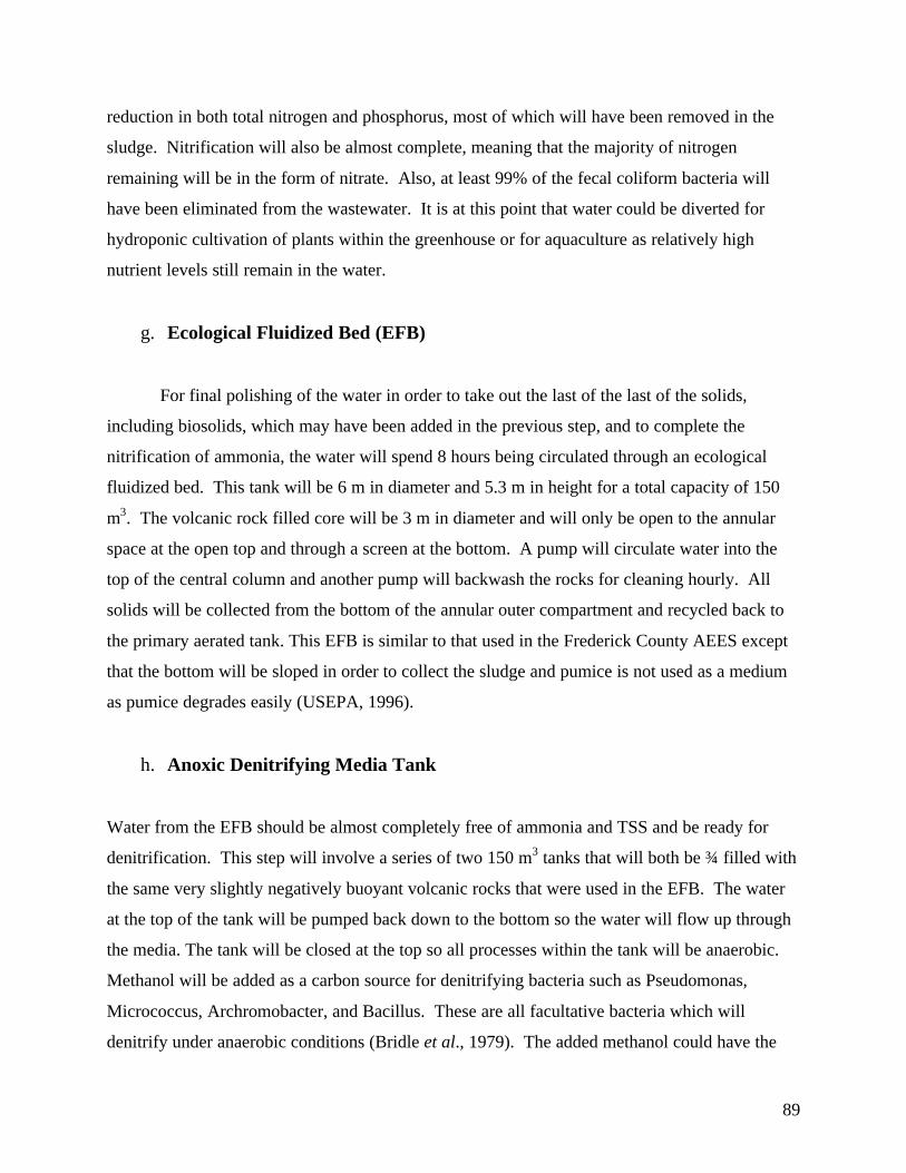
89
reduction in both total nitrogen and phosphorus, most of which will have been removed in the
sludge. Nitrification will also be almost complete, meaning that the majority of nitrogen
remaining will be in the form of nitrate. Also, at least 99% of the fecal coliform bacteria will
have been eliminated from the wastewater. It is at this point that water could be diverted for
hydroponic cultivation of plants within the greenhouse or for aquaculture as relatively high
nutrient levels still remain in the water.
g. Ecological Fluidized Bed (EFB)
For final polishing of the water in order to take out the last of the last of the solids,
including biosolids, which may have been added in the previous step, and to complete the
nitrification of ammonia, the water will spend 8 hours being circulated through an ecological
fluidized bed. This tank will be 6 m in diameter and 5.3 m in height for a total capacity of 150
m3. The volcanic rock filled core will be 3 m in diameter and will only be open to the annular
space at the open top and through a screen at the bottom. A pump will circulate water into the
top of the central column and another pump will backwash the rocks for cleaning hourly. All
solids will be collected from the bottom of the annular outer compartment and recycled back to
the primary aerated tank. This EFB is similar to that used in the Frederick County AEES except
that the bottom will be sloped in order to collect the sludge and pumice is not used as a medium
as pumice degrades easily (USEPA, 1996).
h. Anoxic Denitrifying Media Tank
Water from the EFB should be almost completely free of ammonia and TSS and be ready for
denitrification. This step will involve a series of two 150 m3 tanks that will both be ¾ filled with
the same very slightly negatively buoyant volcanic rocks that were used in the EFB. The water
at the top of the tank will be pumped back down to the bottom so the water will flow up through
the media. The tank will be closed at the top so all processes within the tank will be anaerobic.
Methanol will be added as a carbon source for denitrifying bacteria such as Pseudomonas,
Micrococcus, Archromobacter, and Bacillus. These are all facultative bacteria which will
denitrify under anaerobic conditions (Bridle et al., 1979). The added methanol could have the

90
disadvantage of raising the BOD if added in excess of requirements (USEPA, 1996). Because of
this, experimentation must be done to determine the minimum amount of methanol that can be
used and we could also try putting this step before the EFB in order to oxidize the BOD.
Total residence time for this step should be about 12 hours depending on the porosity of
the media layer. At this point the water is of advanced tertiary quality with very low levels of all
contaminants except for phosphorus. The water exiting the denitrifying media tank should be
suitable for non-potable reuse. This is conditional upon the fecal coliform levels being suitably
low and some disinfection may be required (see Table 4.4). A denitrifying tank was used in the
Frederick County AEES, but it was simply an EFB with a closed top and no aeration to create
anoxic conditions. The pilot project tanks are different in that they are completely filled with
media and will therefore be more efficient.
i. Sub-surface Wetland
The final component of the system will consist of a sub-surface wetland system, similar
to the wetland discussed in section 4.3. Wetland plants will be grown in a gravel medium (1m
deep), and both roots and rocks will serve as substrates for microbial attachment. Because a long
narrow wetland is desirable for maintaining a constant flow rate the wetland will follow a
serpentine path, in order to minimize the total ground area needed. This component will have a
hydraulic capacity of 189 m3, with dimensions of 9.45 m by 20 m. The channel will be 3 m wide
and will consist of a series of switchbacks within the stipulated areas. The wastewater in the
wetland will be retained for approximately 12 hours.
Using processes previously discussed, microbes will degrade any remaining organic
compounds to inorganic forms, to be taken up by the plants. Both nitrogen and phosphorus can
be removed from the wastewater this way. Removal rate is dependant on plant growth, and can
be optimized by regular harvesting of the plants. Phosphorus removal can be further enhanced
with filtration of the effluent through a slow sand and bauxite filter. Bauxite refining residue (a
red mud) has been found to be an effective phosphate remover (Ho, 2000), and can be easily
mixed with sand.

91
j. Conclusion
The water which leaves the treatment centre will be of the highest quality for renovated
wastewater with less than 10 mg/L BOD, 10 mg/L TSS, 5 mg/L total N, and 3 mg/L P (Living
Machines Ltd, 2001). It will be suitable for many applications throughout campus, which are
detailed in the reuse section. If sufficient non-potable infrastructure is not in place at the time of
plant completion, it could be sent to the Iona treatment plant through the existing piping system.
It is the hope of this group, however, that all of this water be reused to satisfy all of the non-
potable water needs of a small portion of the campus. If all new buildings were designed with
dual water supplies prior to their being built, the implementation of water reuse would be much
less expensive. A summary of the treatment process is illustrated in the following diagram.
FIGURE 4.2 SUMMARY DIAGRAM FOR PILOT SCALE WASTEWATER TREATMENT

92
k. Costs Of The Pilot Plant
It is beyond the scope of this thesis and the ability of those working on it to come up with
exact numbers of what our specific system would cost. But, as cost is one of the most important
aspects of any proposed project some approximate figures are given here. These numbers are
based on the cost of existing treatment systems. The USEPA evaluation of the Fredrick county
AEES breaks down the cost of three different technologies for 80,000 gal/day (302.8 m3/day)
systems. The costs of all three systems were about the same and all share similarities with ours.
From this it can be estimated that this system will have a capital cost of $1,150,000 and an
annual operational cost of $215,000, which would include labour, maintenance, energy, and
chemicals used. To corroborate these figures, Kim Rink, the president of Ecotek, a company
which builds solar aquatics, said that a 600,000 gal/day (2271 m3/day) system would cost about
$5.6 million. So from that you arrive in the same area of a little over $1 million for our system
given a slight loss in economy due to its smaller scale (Rink, 2001).
II. Full Scale Treatment Plant
Following UBC's successful operation of the pilot plant a larger plant could be built in
order to treat all of the school’s almost 3.5 million gallons/day (13,247.5 m3/day) of current
sewage as well as future increases in wastewater production which are inevitable as new housing
developments are built on campus. Because of the large size of any plant capable of treating
such large sewage volumes, it could only be located on the south area of campus and most likely
on the south side of 16th avenue. Wastewater generated on the north side of campus would have
to be drained to a central pump station and pumped over to the plant. The larger plant could be
an expanded version of the pilot plant with some adjustments based upon experience gained
through operation of the smaller plant. There may also have to be some changes made due to
cost and land use constraints of the full sized plant. For example, the solar aquatics aspect of the
system may play a smaller role, as it cannot be as efficiently expanded to a larger scale due to the
necessity of shallow tanks and sunlight. A 4 million gal/day (15,140 m3/day) treatment plant
would cost over $18 million to build and could cost as much as $2 million per year to operate
(USEPA, 1996).

93
Chapter 5 - Synthesis Of Stormwater And Wastewater
5.1 Summary Of Proposed System
The proposed system is comprised of three different parts, all of which affect UBC’s
current system: the management of storm flow runoff, the rainwater harvesting from rooftops,
and the management of UBC’s sewage. Management of storm flow runoff attempts to limit two
main characteristics of the water: water quality and peak flows. Currently, UBC’s runoff
contains sediments, metals, and other pollutants typical of urban runoff. Some of this water
flows through vegetated channels, which naturally act to increase water quality by filtering and
contaminant uptake, but no direct attempt to ameliorate water quality has been made. There is
also no attempt to directly attenuate the peak flow of storm events. Measures are being proposed
to upgrade the system to handle peak flows, treat water quality, and reduce Point Grey Cliff
erosion. A proposal was put forth (by Alpin & Martin) to build a large, and costly biofiltration
swale, which would theoretically act to remove sediments and metals from the water. Our
proposed system suggests a cheaper and simpler method that can be set up throughout the
campus. The numerous small detention ponds, developed from best management practices,
would temporarily pool the water behind small check dams; ultimately dissipating the peak flows
of storm events. Additional benefits of the ponding allow for more settling of solids to occur and
potentially more time for plants to incorporate pollutants into their biomass. The overall effect
would be a decrease in the erosive capacity of the water and an increase in the quality of the
water. This directly improves the erosion situation for the Point Grey Cliffs and it directly
improves the water quality in the Fraser River estuary.
Of the rainwater that falls on the UBC campus, the majority of it hits the ground.
Although only a small fraction of water hits the rooftops of buildings, upon proper management,
it can still significantly improve many aspects of the overall water situation in the lower
mainland. If the water is collected, it would take away from the storm flow water that, at high
flows, can be damaging to the environment. The collected water can also be filtered and used for
many applications. Using the water to fulfill needs currently met by the GVRD, would decrease

94
the demand on the GVRD water supply. There is also an indirect effect in that it would decrease
the number of overflows in the GVRD sewage treatment system.
The wastewater that leaves UBC and goes to the GVRD enters the Iona Sewage
Treatment Plant. It is here that millions of dollars in upgrades are required because the plant
does not meet current standards for the effluent that is dumped into the Fraser River. The
effluent potentially has deleterious effects on aquatic species and may have adverse health
effects on humans. By implementing sewage treatment on the UBC campus, the volume of
sewage outgoing to Iona will be reduced allowing the GVRD to spend their savings upgrading
the quality of the treatment at Iona and not just the quantity of treatment. On UBC campus, the
proposal for a treatment facility carries many more implications. The proposed system uses a
combination of solar aquatic technology and conventional technologies. A facility of this type
on campus will allow for research and experimental applications for a variety of uses. Some of
which could decrease the water used from the GVRD, which again, decreases the demand on the
GVRD for both water and sewage treatment and disposal. Research could be done on the facility
itself with the new solar aquatic technology and the use of different plants in temperate regions,
or research could be done with the application and reuse of the effluent and sludge obtained from
the treatment.
Overall, the three different parts of the proposed water management system have multiple and
diverse improvements to some part of environment. All parts also act to accomplish the thesis
goals of improving sustainability, research opportunities, and UBC independence from the
GVRD.

93
5.2 Proposed Water Balance
FIGURE 5.1 PROPOSED WATER BALANCE FLOW CHART

94
The proposed water balance flow chart is a visual representation for the proposed
movement of water through the system at the University of British Columbia. The arrows do not
represent the volume of water flowing from one system to the next, just the direction.
Much of the proposed system still flows in a similar manner to the current system. The
only difference is a few new stages were created that redirect some of the water to different areas
for treatment or reuse.
It is easiest to look at the new stages in terms of water management and water usage.
Water management is composed of three new stages: ‘Rooftop’ rainwater harvesting, ‘Numerous
Small Detention Ponds’ as a subsystem of the stormwater runoff system, and ‘Treatment Plant’
for sewage treatment. Rainwater harvesting redirects precipitation away from simply entering
the ‘stormwater runoff system’ to more useful applications such as ‘fire fighting’, ‘emergency
use’, ‘general use’, and ‘irrigation’. The ‘numerous small detention ponds’ process the
stormwater runoff before going over the cliff and entering the ocean. While passing this stage,
the ponds act to slow the rainwater and potentially clean the water to cause less damage to the
cliff side and to life in the ocean. The ‘treatment plant’ stage plays a large role in reducing the
amount of sewage that will be sent to the GVRD for processing. The treatment plant system has
the potential to convert the sewage into usable forms for experimentation, general applications,
and land applications.
Water usage is composed of four new stages: ‘emergency use’, ‘fire fighting’ use,
‘general use’, and ‘experimental application’. The ‘emergency use’ stage is a storage stage that
holds water for times of emergency. The ‘fire fighting’ stage is the same as the emergency stage
in that water is stored for times of emergency. Both stages can receive treated water from the
GVRD or from rooftop harvesting. The ‘general use’ stage is for the re-application of harvested
and treated water. The water can be used for a multitude of applications such as domestic use,
academic use, and industrial cooling. UBC is the perfect institution to develop this technology
and test ‘experimental applications’ to see where and how this treated sewage can be used and
distributed.

95
PV = Vt x 1 .(1+r)t
5.3 Multiple Account Analysis
I. Introduction
A multiple account evaluation is used to evaluate the costs and benefits that emerge from
the alternative water management strategies and wastewater treatment systems discussed in this
paper. This method highlights benefits and costs that should be included in decision-making. It
compares options by assessing each from the perspective of categories, called accounts,
previously defined by the evaluator(s). There is an array of categories that could be accounted
for, but not all are relevant to every project. The evaluator or group of evaluators decides which
accounts are relevant to their project. The types of impacts and effects distinguish each category;
for instance the ecological damage to a fish-bearing stream is a cost under the environment
account not the financial account. The benefit of a multiple account evaluation is that it does not
aggregate all costs and benefits or require that they be expressed in monetary terms. Multiple
account evaluation is used as a tool for decision-making but does not yield a “yes or no” answer.
The costs and benefits of our proposed alternatives for UBC, (rainwater harvesting,
wastewater treatment and temporary detention ponds), are assessed and compared to the status
quo. Each system is compared to its respective component in the status quo and all systems as a
unit are compared to the total status quo. Accounts for financial, environmental and social
effects are used in this evaluation. The financial account, discussed first, is evaluated in
monetary terms and the other two accounts are qualitatively assessed in reference to the critical
value (see Glossary), which is calculated from that account.
The costs and benefits are evaluated over a 20-year period from the beginning of 2002 to
the end of 2022. A discount rate (r) of 7%, as recommended by Tietenberg, is used to calculate
the costs in terms of present value (PV) by Equation 5.3.1 (1996). The variable t represents the
years from implementation of the project, therefore in 2002 t = 0. A discount rate of 5% is also
used to test the sensitivity of results to future costs. All costs are real values not nominal values
as nominal values include inflation.
Equation 5.3.1

96
Wt = C2001 x 2%
In places all over the world and especially in BC, there are problems with how water is
priced. In Vancouver water is priced by the GVRD, which forecasts the next year’s demand and
then determines the cost of producing that amount of water. The average price they will charge
for water next year is the total cost of the forecasted demand divided by the total volume. There
are a few problems with this system. As Tom Tietenberg states, “ in order to adequately balance
conservation with the use, the customer should be paying the marginal cost of supplying the last
unit of water”(1996), this is not done in Vancouver. Since the average, not marginal cost is used,
if the forecast were to fall short of actual demand, the GVRD would not be charging enough to
offset the production costs on that supply of water. Another problem is that the cost of water in
Vancouver does not include “marginal scarcity rent”, which incorporates the marginal user cost
(Tietenberg, 1996). For these reasons, water prices in Vancouver are unsustainably low. To
account for the low cost of water the discount rate will not be lowered, as this would create
problems such as the putting off the project indefinitely on the basis that it will be more cost
effective next year. It would also problematically discount all factors including sewage and
labour at a low discount rate when it is not merited. Instead, the price of water is allowed to
increase from year to year, an approach that is supported by both Tietenberg (1996) and
Winipenney (1991). The underlying principle is, as future water supply becomes increasingly
scarce, it also becomes more precious to us. The increase is estimated at 8%, and is used to
calculate the cost of water per 1000L in year t, (Wt), by Equation 5.3.2, where C is the price of
water per 1000L in 2001. In 20 years an increase in water prices of 8% each year results in a
price of $1.36/1000L for water and sewage ($1.16/1000L for water plus $0.20 for sewage) this
does not seem unreasonable as Edmonton currently pays $1.95/1000L for water and sewage
(Pate, 2001).
Equation 5.3.2
II. The Financial Account
The financial account looks at the present cost of the project in comparison to the status
quo. The present value of the status quo is determined by summing the present value of costs

97
At = A2001(1+ I)
I1 = (R2006 + E2006 ) x 1 x 1 . R2001 E2001 2 2006-2001
I2 = (R2021 + E2021 ) x 1 x 1 . R2006 E2006 2 2021-2006
UBC will incur from 2002 to 2022 due to water usage and sewage production. The cost of
water, for reasons explained above, is given in Equation 5.3.2, C2001 = 25.07 cents/1000L
(Marques, 2001). The cost of sewage is 19.63 cent/1000L and is assumed constant throughout
the project, as sewage disposal does not increase in value.
The amount of water used and sewage produced is assumed to increase with population
growth. UBC estimates population growth in terms of residence and employees in their Official
Community Plan. Since this does not address students living off campus, the average increase
from these areas will be used as the increase for the UBC population as a whole. By 2006, UBC
is planning to increase the number of people living on campus (R2006) by 4,000 and increase the
number of jobs (E2006) by 700, by 2021 these increases will be 5,300 (R2021) and 900 (E2021)
respectively (UBC Official Community Plan, 2002). Currently there are 8,700 people living on
campus (R2001) and 9, 079 working on campus (E2001), therefore the average increase per year is
calculated by Equation 5.3.3. From this equation the increase each year up to 2006 (I1) is 5.4%,
and 1.6% per year after that till 2021(I2). The growth form 2021 to 2022 is assumed to be the
same as the growth per year estimated to 2021.
Equation 5.3.3
Using I1 and I2 calculated above, Equation 5.3.4 is used to extrapolate the 2001 amount of
water usage and sewage production (A) to 2002 and later years. It is assumed that all water and
sewage on campus is affected by this population growth. These assumptions are not necessarily
an accurate representation of what occurs from one year to the next: expansion is geared more
heavily toward some years than others, not all water use is population dependant and the
population increases based on averages. However, they do allow for a reasonable estimate of
future water use and sewage production.
Equation 5.3.4

98
Table a, Appendix IV, provides the costs of both water usage and sewage production
each year until 2022. The total cost of the status quo over the next 20 years is roughly $65.4
million. Costs were also summed per year to give the cost since 2002 to any year after, the cost
to present column in Table a, Appendix IV. This information is illustrated in Figure 5.2.
$0
$10
$20
$30
$40
$50
$60
0 5 10 15 20
Time (years)
Co
st in
Mill
ion
s
Water Cost
Sewage Cost
FIGURE 5.2 WATER AND SEWAGE COSTS OVER THE NEXT 20 YEARS
Our proposed system would allow UBC to be more independent from the GVRD, cutting
water demand and thus cost. There are three components of our proposed system: rainwater
collection (Table b, Appendix IV), wastewater treatment (Table c, Appendix IV), and temporary
detention (Table d, Appendix IV). Each component is analysed separately and, since the
rainwater harvesting system could be hooked up to the wastewater treatment facility, these two
components are analysed as one system. Costs include one-time purchases such as the materials,
installation and land, as well as costs that will occur over the next 10 years such as maintenance.
The costs of the rainwater collection system include installation, maintenance, storage
tanks, corrugated aluminium sheets, pipes and filters (the last three costs are aggregated under
system costs. The storage tanks are the most expensive parts of the system costing $30,713 for
the 12,000-gallon tanks and $92,141 for the 48,000-gallon tanks (Water Tanks, 2001).
Maintenance costs are low for the collection system as it is relatively simple and could be woven

99
into a Plant Operations job. Maintenance and installation costs were estimated at $50/hr, the
price UBC pays for skilled labour (Mazzi, 2002). Installation of the rainwater harvesting system
is estimated to take 8 labourers, 8 hrs/day, three weeks and maintenance one labourer 8
hrs/month every year. The system has the ability to supplement 400,000,000 L of water demand
with rainwater each year. Figure 5.3 shows how costs of the system, maintenance and
installation compare to water savings over the next 20 years. As illustrated in the graph, by the
intersection of the cost and savings lines, the project pays for itself in just over 15 years. Even if
the rainwater system only supplemented 100 million litres it would pay for itself within a 20-year
time frame. Table 5.2 shows the cost of the rainwater system plus the cost of water demand that
is not supplemented by the system over the 20-year period.
$0.0
$0.5
$1.0$1.5
$2.0
$2.5
$3.0
0 5 10 15 20 25
Time (years)
Do
llar
Am
ou
nt
(Mill
ion
s)
Cost
Water Savings
FIGURE 5.3 RAINWATER HARVESTING COST AND SAVINGS OVER TIME
The pilot wastewater treatment facility has the capacity to treat 378,541 L of the sewage
and reduce water demand by the equivalent amount. The costs include the system and
installation at $1.15 million, storage and treatment $190,000, maintenance at $210,000/year, and
land $519/m2 (Barrs, 1995). The pilot facility costs $18.9 million generates saving both from
supplemented sewage treatment and water production. Figure 5.4 shows that these savings do
not pay for the system in 20 years, but it may in the future.

100
$0
$1
$2
$3
$4
$5
0 5 10 15 20 25
Time (years)
Sav
ing
s (M
illio
ns)
Watsewater Facility Cost
Water + Sewage Savings
FIGURE 5.4 WASTEWATER FACILITY AND SAVINGS OVER THE NEXT 20 YEARS
The costs of the rainwater harvesting and wastewater facility sums to $68.3 million and
comparing this to the above estimate places the cost of the project at $2.9 million more than the
status quo. The comparison of savings to system costs is represented in Figure 5.5. $2.9 million
as listed in Table 5.4, is referred to as the critical value. Theoretically, since reduction of water
demand from the GVRD is a function of our project and the GVRD benefits from this reduction,
they may be willing to contribute to the overall cost of the project, thus reducing the critical
value.
$0
$1
$2
$3
$4
$5
$6
0 5 10 15 20 25
Time (years)
Do
llar
Am
ou
nt
(Mill
ion
s)
Cost
Savings
FIGURE 5.5 WASTEWATER FACILITY AND RAINWATER HARVESTING COST AND SAVINGS OVER
THE NEXT 20 YEARS

101
Our temporary detention ponds are compared to the Alpin & Martin proposal, which
costs approximately $1.45 million. The supplies for our temporary detention pond channel
include sandbags ($0.46/bag), 10ft by 5ft pieces of plastic ($0.15/sheet), and PVC pipes($1/ft)
(Dawson, 2002). These costs sum to $5.75/10m length of channel, and since there are
approximately 10,000m of ditch that could be changed into temporary detention pond channels
on campus, this amounts to $5,750 in supplies. The channel will also contain 20 plants/10m and
each plant is priced at $2 (Pinette, 2002). Installation is estimated to take 2½ hrs/10 m at $48/hr
and maintenance 1 hr/week also at $48/hr (Dawson, 2002). Maintenance every 10 years includes
dredging and replanting, which is estimated to take twice the time as regular maintenance, on top
of regular maintenance costs. The comparison shown in Table 5.1 makes it apparent that our
proposed channel would be more cost effective than theirs, serve the same function, as well as
improving aesthetics and increasing habitat for wildlife.
Table 5.1-Temporary Detention Pond Channel Compared to The Alpin & Martin Proposal(2001)
Account Temp. Detention Pond Channels Alpin & MartinFinancial S $0.36 million S $1.45 million
Social S AestheticS Decreased Erosion
S Decreased Erosion
Environmental S Improved water quality S Improved water Quality
III. The Social and Environmental Accounts
The social account includes different social benefits that occur to slightly different parts
of society. Many in the UBC community will attribute an existence value to our project because
UBC has increased independence from the GVRD and has become more sustainable and
environmentally responsible. The sewage treatment plant, a solar aquatic system, could be used
as a research and educational facility and thus has a use value to researchers as well as users.
SFU has estimated this to be worth $60,000 over 10 years from the cost benefit analysis of a
solar aquatic system in a proposal they created (SFU, 1999). This is an underestimate, as SFU
only included revenue from specific educational programs and did not include research value.
There would also be a positive option value inherent in having two supplies of water, if one
supply is cut-off then the other could supplement as a back up. For instance, if there is an
earthquake that severed the pipes running from the GVRD to campus, or the GVRD watersheds

102
became infected with Cryptosporidium or Giardia, the water from the sewage treatment and
rainwater collection could be rationed out for use or visa versa if water produced on campus
becomes unusable. Since we are decreasing our reliance on the GVRD, but not severing our
connection with them, UBC only increases its options. The actual benefit of this may very likely
be small as the likelihood of these events is low, however the perceived benefit will probably be
greater especially in light of recent water contamination issues in Ontario. Another benefit of
our project is that UBC will decrease its demand on the GVRD watersheds. Decreased erosion is
another benefit due to rainwater harvesting and stormwater detention. Erosion is a major issue
on campus that involves various groups from all over Vancouver. Erosion is a natural process,
so the account that suffers most from high erosion is the social account. A lot of money is spent
on erosion control, as it is socially undesired. Therefore, erosion control could also be
categorized in the financial account. However, it is difficult to estimate the dollar savings that
could arise from our alternatives as the relationship between runoff and erosion amounts is
largely unknown and the number of interest groups involved is large. Therefore the best way to
include erosion in this evaluation is as a non-monetary factor.
From an environmental perspective these alternatives help UBC become more
environmentally friendly by reducing our impact on our natural resources. If the project were
implemented, UBC would decrease its impact on the GVRD watersheds. The watersheds have
been manipulated to produce water Vancouver and its surrounding municipalities. At present the
impact of this activity has little detrimental effect on the surrounding area, however, increasing
demand and climate change bring the possibility of more severe strain on the water supply and
biophysical region. The situation at the Iona Island Sewage Treatment Facility is much the
same; impacts on the environment are poorly understood, but may be found to be serious over
time. If deleterious environmental effects of the facility become prominent, the cost to upgrade
the Iona Island Sewage treatment system to secondary treatment would be in the $400 million
range (Nenninger, 2001). The UBC facility would treat water one step further through tertiary
treatment. The environmental benefit is that UBC decreases the possibility for environmental
damage. Another environmental benefit that is difficult to put a value on involves the ability of
temporary detention ponds to improve stormwater quality. The levels of pollution that have
entered the Georgia Strait and the Fraser River from UBC have not been documented, therefore

103
the effects of poor quality water going into the Georgia Strait are unknown and there is no data to
compare improvements in quality to.
IV. Results and Conclusion
Tables 5.3 to 5.3 show each alternative system compared to the status quo. The social
and environmental accounts in the tables only show benefits; costs of the alternatives are the
opposite of the benefits of the status quo and visa versa. As Table 5.2 shows rainwater
harvesting is economically cost effective and is associated with a variety of benefits. The on
campus wastewater treatment facility cost is more than the status quo revealing that it is the most
expensive component of our proposal. The $2.9 million dollar difference in Table 5.4 is due to
the treatment facility. Combining the two systems allows the rainwater savings to go towards
paying for the wastewater system. The integration of the two systems also cuts cost by at least
$190,000, as some of the components can be shared.
Table 5.2-Rainwater Harvesting Compared to Receiving all Water from the GVRD
Account Rainwater Harvesting Just GVRDFinancial S $49.6 million S $50.4 million
SocialS Independence + sustainability
S Decreased ErosionS Reliable
EnvironmentalS Less impact on the Capilano
and Seymour watershedsS
Table 5.3-Wastewater Treatment on Campus Compared to Sending all Wastewater to the GVRD
Account On Campus Treatment Just Iona IslandFinancial S $18.9 million S $15.0 million
Social
S Independence from theGVRD+ more sustainable andenvironmentally responsibleS Research facilityS Backup plan
S Out of sight out of mind
EnvironmentalS Less sewage to IonaS Decreased impact on the
watershedsS

104
Table 5.4 The Rainwater Harvesting and Wastewater Treatment at UBC vs. the Status Quo
Account FactorsFinancial S $2.9- the cost of the project above the status quo
Social S Independence from the GVRD+ more sustainable andenvironmentally responsible -existence value
S Research facility-use valueS Backup plan –option valueS Decreased erosion
Environmental S Less impact on the Capilano and Seymour watershedsS Less sewage to Iona
S Cleaner Water going into the Georgia Strait
Table 5.4 summarises the multiple account information for the rainwater harvesting and
the wastewater treatment facility. It is likely that the social benefits of the project have more
value then the environmental benefits, at least in the short term. For the project to be cost
effective, the benefits of the social and environmental accounts would have to outweigh or
balance the critical value $2.9 million dollars over a 20-year period. The trade-off is financial
cost for the decreased risk of environmental damage, increased flexibility to respond to uncertain
events, and social benefits.
Table 5.5 Cost and Pay off Period for the project Under Different Discount Rates
Discount Rate, Water Increase Cost at 20 years(millions)
7% Discount, 8% H2O increase $2.9
4% Discount, 8% H2O increase $2.5
Table 5.5 shows that changing the discount rate to 4% increases the cost of the project in
comparison to the status quo by about $0.4 million dollars. Lowering the discount rate has this
effect because the project is capital intensive; it incurs higher costs upfront and lower costs in the
future. The 4% discount rate shows that the assumed cost of capital does have a noteworthy
effect on the evaluation of the project in respect to the status quo, but would still leave the status
quo less expensive than the alternative in a 20-year timeframe.
The evaluation, and thus decision for project implementation depends not only on the
costs and benefits of the project, but also on the valuation of the benefits, the assumed cost of
capital, and the timeframe in question. $2.9 million dollars over the next 20 years is not an
unfeasible or unreasonable cost for UBC to incur in comparison the value of the benefits.

105
Chapter 6 - Conclusion And Future Recommendations
6.1 Conclusion
This project has encompassed a variety of water management issues as they apply to the
University of British Columbia, as well as implications of these issues to the larger world. We
have examined possible stormwater management and rainwater collection systems, and
alternatives to the current wastewater management strategy. A broad overview of these topics is
included as well as detailed discussions regarding the applications of these systems to UBC. A
comprehensive analysis has been produced that will hopefully lead to the further application of
such systems at UBC. In the end, we hope to have demonstrated the values of undertaking the
proposed changes, and we hope that some (or all!) of our proposals will be incorporated into the
UBC water system in the future. It is our opinion that considerable environmental, social, and
(in some instances) economic benefits can result from the use of such sustainable practices. It is
hoped that our project will not only affect the views of the UBC community, but also those of the
GVRD, the nation, and beyond.
The proposed stormwater treatment system would realise a number of environmental
benefits, including the protection of natural waters from hydrocarbon, heavy metal and sediment
contamination. While no official treatment is currently underway at UBC or in the GVRD, we
have proposed a system involving temporary detention ponds. This system is shown to be more
cost-effective than biofiltration options, and also includes aesthetic benefits.
The benefits of on-site rainwater harvesting are discussed in this thesis. These include
the roof-top collection of rainwater for a variety of applications, primarily for use in irrigation of
UBC’s lawns and gardens and for general domestic use (not including drinking needs). The
collected water can also be stored as an emergency water supply, or for firefighting. An
extended benefit of rainwater harvesting on campus is the decreased dependence on the GVRD's
water system and decreased contribution to erosion.
With respect to the current wastewater system for UBC, we feel that major changes must
be made to improve environmental sustainability. Currently wastewater from UBC is sent to the
Iona Wastewater Treatment Plant, where it is discharged to the Strait of Georgia after only

106
primary treatment. Effluent from Iona and other Lower Mainland WWTPs has failed recent
quality standards. The development of the pilot wastewater treatment system proposed in this
project would hopefully act as an example of an effective and sustainable treatment option that
may induce upgrading of the current infrastructure. Aesthetic values are also incorporated into
the proposed wastewater system with the growth of plants in the subsurface wetland.
Overall, this project has presented a detailed and holistic analysis of the current water system at
UBC. We have proposed alternatives that are aimed at decreasing the amount of wastewater
produced while increasing the effectiveness and sustainability of rainwater, stormwater, and
wastewater systems.
6.2 Future Direction
I. Stormwater Future
The potential future direction of stormwater treatment much depends on the results of the
detention pond experiment. If the Ho of the experiment conducted could be rejected, then our
design and ideas were solid and sound. These ideas could be adopted into UBC stormwater
management with the installation of check dams in every suitable grassed channel throughout
UBC. Those channels that were deemed prone to flooding or debris jams, could be left
unaltered. Managers would like to have accurate information about the effectiveness of the
campus wide system. This could involve large scale testing by injecting tracer dies upstream in
the UBC stormwater system, and following its flow rate, before and after the modifications of
the system. This could determine the amount of peak flow attenuation (similar process to
Pettersson, et al (1999)). Analyzing the concentration of the tracer dye before and after
modification would give an estimate of particle settlement, and removal, assuming that the tracer
chosen sorbs to organic or inorganic material. Maintenance schedules would need to be updated
to ensure ‘temporary’ detention ponds do not become clogged and permanent ponds. Natural
storms could be monitored in the same way our replicated storms were analyzed to bring
confidence that the results obtained were not correlated to the artificial storm flows.
Plants could be planted and tested for their role in decreasing flow velocity, nutrient
uptake, metal removal, habitat for wildlife, and aesthetic value. Plants species, as recommended

107
by Table 3.4, require planting a number of months before testing during warm weather. The
same monitoring stations used in the experiment could be used to collect the conductivity,
turbidity, and suspended sediment. But a new protocol would need to be used to determine the
amount of heavy metal removal by a plant. Tissue samples of the plants would need to be taken
before and after experimentation to determine if specialized plants are more effective at
removing metals than grass. The grass would also need to be tested as a control for comparison.
The GVRD could include the usage of numerous small check dams in their stormwater
treatment section of their Best Management Practices Guide. This would enable others
communities to make modifications to their existing channels or enable them to design numerous
detention ponds at the planning stage.
II. Rain Harvesting
The proposed rainwater harvesting, filtering, and storage system does not have to be
implemented all at once. Small adjustments can be made over time to reach the goal of the
proposed system. Other options for rainwater harvesting include courtyard and ground
catchments.
Courtyard catchments would include any paved or terra formed ground that can act as a
collection watershed. The water can be funnelled into storage facilities and can later be used for
irrigation purposes. The water would contain more sediments and pollutants than water collected
from rooftops, but with proper filtering it too could be used for general applications.
Ground catchments on UBC campus will basically involve the stormwater runoff system
(i.e. swales and check dams). Instead of directing the stormwater flow off the cliffs, the water
could be used in other ways. Similar to courtyard catchments, it could either be used for
irrigation or for general applications (after filtering).
If all these management techniques are used and the water is not to be filtered, but more
water is collected than needed for irrigation needs, the water could be used off campus. The
water could be sold to surrounding communities for the irrigation of lawns and fields.
Ultimately, this would reduce the demand of water from the GVRD.

108
III. Wastewater Treatment At UBC
Any treatment system implemented at UBC would require the allocation of some land,
which will be occupied by a treatment plant. As land is quite limited on campus, with many
different interests competing to develop it, it is an important first step to secure an area for a
treatment plant. Energy use in a treatment process is a very important factor when assessing the
sustainability of a process for a given level of treatment. Energy is used for heating of the
wastewater and for the operation of mechanical systems such as pumps and air compressors.
Further research and consideration is needed to make the pilot treatment plant as energy efficient
as possible. This would include the use of materials in the SA greenhouse, which minimise the
heat lost from the process and using gravity to transport the wastewater as much as possible.
There is also a biological component to energy efficiency as different species of plants and
microbes could be experimented with to determine which help treat wastewater most efficiently
at cooler temperatures. If a pilot plant is built at UBC the potential for experimentation will be
great in fields such as microbiology, materials engineering, botany, biology, civil engineering,
and landscape architecture. From a social standpoint, a pilot plant, like the one proposed in this
thesis, could help change the way in which our society views wastewater. Just as discarded
paper was once thought of as a waste to be disposed of, and is now considered a commodity to
be conserved and reused, we may begin to view wastewater as a resource. Future experiments in
using both wastewater and sludge in agriculture or aquaculture could be conducted at UBC.
Also, reusing water within buildings for flushing toilets and urinals may pave the way for the
acceptance of reused water for other uses, like washing clothes, which are currently prohibited in
BC.
IV. Environmentally Sound Initiatives
The alternatives addressed here are only some of the possible changes that could make
UBC a more environmentally sound institution. There are a myriad of other issues that the
university could take responsibility for, in order to reduce its ecological footprint.
Transportation to and from the University is especially important, as Vancouver’s topography
facilitates air quality problems. As air quality gets worse and single occupancy vehicles become

109
more common, UBC is an establishment that can step forward and act as the catalyst for change.
Programs and initiatives have already started in this area; however, UBC has not given them the
priority they deserve. A strong commitment to improving transportation options means making
less popular changes. UBC also has the ability to ensure that products sold and used on campus
come from institutions that participate in fair trade, equitable practices and ecologically sound
operation. The most prominently future initiative should be to make environmental
responsibility synonymous with UBC. For instance, when the slogan, Tuum Est or ‘it’s yours’ is
used, the underlying principle should be that it is each individual’s opportunity and responsibility
to make a difference.
110
Bibliography
Aabasi, S.A. “Aquatic Plant-Based Water Treatment Systems in Asia.” Aquatic Plants ForWater Treatment and Resource Recovery. Ed. Reddy and Smith. Magnolia, 1987: 175-198.
Alpin & Martin Consultants Ltd. Master Servicing Plan: Stormwater Management, TechnicalReport. Oct. 2001.
Alpin & Martin Consultants Ltd. UBC Properties Inc. and UBC Utilities. University of BritishColumbia Master Servicing Plan: Sanitary Sewers Technical Report. File 99110H. 2000.
Barrs R, et al. Waste Management: A UBC Policy Initiative. UBC School of Community andRegional Planning. 1995.
Bear River Solar Aquatics. 2000. November 23, 2001.<www.collections.ic.gc.ca/western/bearriver.html>.
Bestbier, et al. Urban Watershed Management (Cdrom). UBC, 2000.
Bowes G. and S. Beer. “Physiologica Plant Processes: Photosynthesis.” Aquatic Plants ForWater Treatment and Resource Recovery. Ed. Reddy and Smith. Magnolia, 1987: 289-294.
Bridle T., H. Monteith, and P. Sutton. Evaluation of Industrial Waste Carbon Sources forBiological Denitrification. Environmental Protection Service, 1979.
Brix, Hans. "How Green are Aquaculture & Constructed Wetlands vs. Conventional WastewaterTreatment," Water Science and Technology 30.1-3 1999: 45-50.
Budd G., G. Logsdon, and B. Long. “Overview of Chlorine Dioxide, Ozone, and UltravioletIrridation”, Providing Safe Drinking Water in Small Systems-Technology, Operations, andEconomics, Eds. Cortuvo, Craun, Hearne, Lewis Publishers, Boca Raton, 1999.
Buras, Netty, et al. “Microbiological Aspects of Fish Grown in Treated Wastewater.” WaterResources. 21.1 1987: 1-10.
Cardil D. Telephone conversation discussing Shadow River Estates: Questions regarding thePeat Bog System. February 21, 2002.
Chau, Lillian. A Study Of Rainwater Harvesting For West Mall Annex Student Offices. ForProfessor B. Rees of PLAN 504, UBC. 2001.

111
CHMC - Canadian Housing and Mortgage Corporation. Modular Peat Bed WastewaterTreatment System. 2001. November 10, 2001. <www.chmc-schl.gc.ca/en/imquaf/himu/wacon/wacon_004.cmf>.
Chomolok, S. (Errington SA Operator). Interview concerning: Questions regarding the SAfacility. Errington, B.C. November 18, 2001.
CMHC - Canadian Water and Wastewater Association. Regulatory Barriers to On-site WaterReuse. CMHC, 1997.
Coast River Env. Services Ltd. UBC Stormwater (01P014) Water Analysis, ALS file numberN9581, January 7, 2002.
Collins M. “Experiences Introducing “New” Technology: Slow Sand Filtration”, Providing SafeDrinking Water in Small Systems-Technology, Operations, and Economics, Eds. Cortuvo,Craun, Hearne, Lewis Publishers, Boca Raton, 1999.
Connell G. “Chlorination Systems”, Providing Safe Drinking Water in Small Systems-Technology, Operations, and Economics, Eds. Cortuvo, Craun, Hearne, Lewis Publishers,Boca Raton, 1999.
Cronk J., and S. Fennessy. Wetland Plants Biology and Ecology. Lewis Publishers, Boca Raton,Florida, 2001.
Dawson K. RE: Biofiltration Swale. Email to Thesis group. March 8, 2002
Deadly Parasites. Medical Detectives. TLC. February 28, 2002.
DeBusk T.A. and K.R. Reddy. “Wastewater Treatment Using Floating Aquatic Macrophytes:Contanimant Removal Processes and Management Strategies.” Aquatic Plants For WaterTreatment and Resource Recovery. Ed. Reddy and Smith. Magnolia, 1987: 643-656.
DeBusk W.F., and K.R. Reddy. “Nutrient Storage Capabilities of Aquatic and Wetland Plants.”Aquatic Plants For Water Treatment and Resource Recovery. Ed. Reddy and Smith.Magnolia, 1987: 337-357.
Doeksen G. and J. Barnes., Economies of Size for Oklahoma Slow Sand Treatment Technology,Oklahoma Extension Facts F-908, Oklahoma, 1998.
Droste R. Theory and Practice of Water and Wastewater Treatment, John Wiley and Sons Inc.,New York, 1997.
Dunn R., J. Stidwill. CMHC Water Quality Guidline and WaterMonitoring Tools for ResidentialWater Reuse Systems. Canada: CMHC, 2000.

112
Environment Canada. Canadian Climate Normals, Vancouver, UBC. 2001. January 12, 2002.<http://www.msc-smc.ec.gc.ca/climate/climate_normals/show_normals_e.cfm?station_id=254&prov=BC>.
EPA. Constructed Wetlands for Wastewater Treatment and Wildlife Habitat. Cannon Beach, OR– Wooded Wetlands for Wastewater Treatment. 2002. February 18, 2002.<www.epa.gov/owow/wetlands/construc/cannon.html>.
Feigin A., et al. Irrigation With Treated Sewage Effluent – Management For EnvironmentalProtection. Springer-Verlag, 1991.
Finkenbine J.K., J.W. Atwater, and D.S. Mavinic. “Stream Health after Urbanization.” Journalof the American Water Resources Association. vol36, no5, October 2000.
Forestry 395, UBC, 2000.
Frost J. Phone conversation regarding the system in place at the C.K. Choi Building, UBC.Vancouver, B.C. January 26, 2002.
Gattinger V. RE: Prince Albert, Sask and RE: Technological Problems. Emails to the thesisgroup. February 21 to February 23, 2002.
GeoFlow. Chlorination. February 22, 2002. March 20, 2002.<www.geoflow.com/wastewater/chlor.htm>.
Gottschalk C., et al. Ozonation of Water and Wastewater – A Practical Guide to UnderstandingOzone and its Application. Wiley-VCH: 2000.
Gould, John, et al. Rainwater Catchement Systems for domestic Supply. 1995.
Green Buildings BC. Beausoleil Solar Aquatics Water Reclamation System. July 20, 2001.November 15, 2001<www.greenbuildingsbc.com/new_buildings/case_studies/Beausoleil_Solar.pdf>.
GVRDa. Sewerage: Combined Sewage Systems. 2001. February 22, 2002.<www.gvrd.bc.ca/services/sewers/collect/CombinedSewers.html>.
GVRDb. Sewerage: Iona Wastewater Treatment Plant. 2001. February 22, 2002.<www.gvrd.bc.ca/services/sewers/treat/Iona/Index.html>.
GVRDc. Nutrifor. 2001. February 22, 2002. <www.nutrifor.com>.
GVRDd. Sewerage: Liquid Waste Planning. February 19, 2001. February 28, 2002.<http://www.gvrd.bc.ca/services/sewers/lwplanning/lwmp%20stage%203/>.

113
GVRDe. Water Conservation. July 12, 2000. January 29, 2002.<http://www.gvrd.bc.ca/services/water/conserve/index.html>
Hares, R.J., and N.I.Ward. Effects of Water Pollution From Roads. In: 11th Annual InternationalConference on Heavy Metals in the Environment. University of Michigan, School ofPublic Health, Ann Arbor, MI. 2000.
Harrison P. (UBC Profesor). Interview regarding the impact of sewage on the Strait of Georgia.Vancouver, B.C. October 15, 2001.
Ho, Goen. “Alternative Technologies for Wastewater Management.” Proceedings of theWorkshop on Sustainable Wastewater and Stormwater Management – RegionalWorkshop for the Latin America and the Caribbean. 27-31 March 2000: 114-155.
Institute of Asian Research, the University of British Columbia. C.K. Choi Building. 2001.January 5, 2002. <www.iar.ubc.ca/choibuilding/Index.htm>.
Jowett, C. Telephone conversation regarding Waterloo Biofilter Systems Inc. and the system inplace at Prince Albert. February 20, 2002.
Kadlec J.A. “Nutrient Dynamics in Wetlands.” Aquatic Plants For Water Treatment andResource Recovery. Ed. Reddy and Smith. Magnolia, 1987: 393-419.
Kantrowitz, I.H., and W.M. Woodham. Efficiency of a stormwater detention pond in reducingloads of chemical and physical constituents in urban streamflow, Pinellas County,Florida. US Geological Survey, Earth Science Information Center, Open-File ReportsSection, Box 25286, MS 517, DENVER, CO 80225 (USA), 1994, 18 pp.
Kominar R.J., Bioavailable Heavy Metal Sediment Loading In Laurel Creek. Department ofChemistry, Wilfrid Laurier University, Waterloo, ON. November 3, 1997. February 25,2002. <http://www.adm.uwaterloo.ca/infowast/watgreen/laurelcreek/17.html>.
Lakshman, G. “Ecotechnological Opportunities for Aquatic Plants – A Survey of UtilizationOptions.” Aquatic Plants For Water Treatment and Resource Recovery. Ed. Reddy andSmith. Magnolia, 1987: 49-68.
Living Machines Ltd. Home Page. 2001. November 18, 2001. <http://livingmachines.com>.
Marques, J. RE: Cost of Water to UBC 2001. Email to Caila Holbrook. November 2, 2001.
Mazza, Patrick. Of storms and slides, logging and development: Second harsh winter in row hasCascadians thinking about human role in "natural" disaster”. Cascadia Planet. March 6,1997. March 10, 2002. <http://www.tnews.com/text/mud.html#6>.

114
Mazzi, E. (Manager, Mechanical Utilities). Meetings and multiple emails consulting with theRainwater Subgroup regarding the temporary detention ponds. Vancouver, BC. October2001 to March 2002.
Melcer, R., and B. Topnik. Conversion of Small Municipal Wastewater Treatment Plants toSequencing Batch Reactors. Canada: Environment Canada, 1987.
Ministry of Land, Water, and Air Protection. Waste Management Act Municipal SewageRegulation. April 23, 1999. March 21, 2002.<www.qp.gov.bc.ca/statreg/reg/W/WasteMgmt/129_99.htm#section%202>.
Nenninger, Fred. Interview with Caila Holbrook. Vancouver, BC. October 24, 2001.
NFPA. NFPA Codes And Standards. 2002. March 7, 2002.<http://www.nfpa.org/Home/index.asp>.
North Carolina State University. Water Shedss, Water, Soil, and Hydro-Environmental DecisionSupport System. 2002. March 10, 2002. <http://h2osparc.wq.ncsu.edu/>.
Orians, Kristin. Chemisty 301 Class Notes. UBC: 2000.
Pair UBC. Faculty and Staff. October 5, 2000. January 29, 2002.<http://www.pair.ubc.ca/faculty/fac&staff_overview00.htm>.
Pate, Joe (President of Enviro Energy International Inc.). Interview with Caila Holbrook.Vancouver, BC. October 15, 2001.
Pazwash, Hormoz. Urban stormwater management practices; concepts and misconceptions.Hydraulic Engineering – Proceedings of the 1990 National Conference, ASCE, Boston,MA, (USA), 1990, pp. 506-511.
Pescod, M.B. “Wastewater treatment and use in agriculture.” FAO Irrigation and DrainagePaper (47). Food and Agriculture Organization of the UN, 1992.
Pettersson, Thomas J.R. Water quality improvement in a small stormwater detention pond.Water Science & Technology [Water Sci Technol], vol. 38, no. 10 pt 8, pp. 115-122,1998.
Pettersson, Thomas J.R., and Gilbert Svensson. Particle removal in detention ponds modelled fora year of successive rain events. Doktorsavhandlingar vid Chalmers Tekniska Hogskola[Doktorsavh Chalmers Tek Hogsk], no. 1542, pp. 567-574, 1999.
Pinette, Roger (Ponds Beautiful Owner). Telephone conversation with Caila Holbrook.Vancouver, BC. January 11, 2002.
Porteous, N. RE: Solar Aquatics Questions. Email to thesis group. November 28, 2001.

115
PromoLife. Ozone Products. 2002. March 20, 2002.<www.promolife.com/products/ozoneh2o.htm>.
Pure Rain Over Texas. UV Products. May 31, 2001. March 20, 2002.<www.purerainovertexas.com/prod02.htm>.
Raindrop Laboratories. Rainwater Harvesting and Purification System. January 15, 2002.February 10, 2002. <http://www.rdrop.com/users/krishna/rainwatr.htm>.
Rink, K. RE: Cost of Solar Aquatics. Email to thesis group. November 6, 2001.
River Works. Fraser Facts. 2000. March 6, 2002. <http://www.riverworks.org/fraser.htm>.
Rouse, J. (Land Use Specialist for the Ministry of Health). Telephone interview regarding reuseof water. March 21, 2002.
Safety Central. Emergency Drinking Water Rations. 2001. March 22, 2002.<http://www.safetycentral.com/waterrations.html>.
SFU. A Sustainable Vision for the Burnaby Mountain Development. 1999. October 24, 2001.<http://www.sfu.ca/bmcp/geog-449>.
Sierra Legal Defence Fund. The National Sewage Report Card (Number Two): Rating theTreatment Methods and Discharges of 21 Canadian Cities. August 1999. February 22,2002. <www.sierralegal.org/reports/Sewage.pdf>.
Slow Sand Filtration. Practical Hydroponics & Greenhouses, Issue 24, September-October 1995.
Smith, David (Landscape and Grounds Supervisor). Meeting with Michael Grant. Vancouver,BC. February 15, 2002.
Stengel, E., et al. “Evidence for Denitrification in Artificial Wetlands.” Aquatic Plants ForWater Treatment and Resource Recovery. Ed. Reddy and Smith. Magnolia, 1987: 543-550.
Sundblad, K., and H.B. Wittgren. “Wastewater Treatment in a Wetland Filter – Effects ofVarying application Frequency on Nitrogen Removal.” Aquatic Plants For WaterTreatment and Resource Recovery. Ed. Reddy and Smith. Magnolia, 1987: 513-523.
Tchobanoglous, G. “Aquatic Plant Systems for WWT: Engineering Considerations.” AquaticPlants For Water Treatment and Resource Recovery. Ed. Reddy and Smith. Magnolia,1987: 27-48.
Tietenberg, T. Environmental and Natural Resource Economics, 4th edition, New York, NewYork, HarperCollins College Publishers, 1996.

116
Todd, John. "The Design of Living Technologies for Wastewater Treatment," EcologicalEngineering 6.1-3 1996: 109-136.
UBC Campus Sustainability Office. UBC Campus Sustainability Office. 2001. November 25,2001. <http://www.sustain.ubc.ca/>.
UBC Library-archives. A Breif History of the University of British Columbia. November 1999.February 27, 2002. <http://www.library.ubc.ca/spcoll/ubc_arch/hist_ubc.html>.
UBC Library-enrolment. UBC Student Enrolment Figures1915-present. June 2000. February 27,2002. <http://www.library.ubc.ca/spcoll/ubc_arch/enrolmnt.html>.
UBC Official Community Plan. UBC Official Community Plan- Summary. 2002. January 29,2002. <http://www.ocp.ubc.ca/ocp/summary.html>.
UBC/Pacific Spirit Park Cliff Erosion Management Planning Consultation DiscussionDocument. The Point Grey Cliffs Need Your Help…An oppurtunity for feedback onoptions toward a cliff erosion management plan. 2000.
UBC Utilities a. Drinking Water Quality Monitoring Program – Draft 2. URBANSYSTEMS,2002.
UBC Utilities b. Emergency Response Plan Water Utility. URBANSYSTEMS, January 2002
United Nations Environment Program. Rain and Stormwater Harvesting in Rural Areas: AReport by the United Nations Environment Programme. 1st ed. Dublin. 1983.
USEPA. Interim Report: Evaluation of the Advanced Ecological Engineering WastewaterTreatment Facility in Frederick County, MD. 1996. January 30, 2002.<http://www.epa.gov/clariton/clhtml/pubtitle.html>.
Water Tanks.com. 2001. October 30, 2001.<http://www.watertanks.com/cat.asp?cat+16&sud=8>.
Waterloo Biofilter Systems Inc. home page. 2001. October 30, 2001 <www.waterloo-biofilter.com>.
Whitehead, A.J. Experimental Culture of Duckweed (Lemnaceae) for Treatment of DomesticSewage. UBC: 1987.
Winipenny, J., Values for the Environment: A Guide to Economic Appraisal, HMSO, London,1991.

117
Wolverton a, B.C. “Aquatic Plants for Wastewater Treatment: An Overview.” Aquatic PlantsFor Water Treatment and Resource Recovery. Ed. Reddy and Smith. Magnolia, 1987:3-15.
Wolverton b, B.C. “Artificial Marshes for Wastewater Treatment.” Aquatic Plants For WaterTreatment and Resource Recovery. Ed. Reddy and Smith. Magnolia, 1987: 141-152.
Wong, et al. “Managing Urban Stormwater using constructed Wetlands.” Industry report, 1997,2nd 1999, CRC for Hydrology + Freshwater Ecology. Monash University, Victoria, Aus,50 p. 1999.
World Bank Home Page. World Bank Development Indicators. 2001. February 27, 2002.<http://www.worldbank.org>.

118
Appendix I – Rooftop Area
Building Name Real Area (based on aerial map) error column m^2 +/- m^21 Thunderbird Stadium 6700 5202 Garden Pavillion 202 373 Botanical Garden Center 755 1274 Totem Park Field Station 965 1265 Landscape Architecture Studio 444 676 Other (Botanical Garden) 95.8 23.67 Other (Thunderbird Stadium) 221 408 Wolfsen II Fields 47.6 15.59 J. Owen 853 100
10 Fornitek 12200 90011 Feric 1270 14012 Salish/Haida 2200 29013 Nootka/Dene 1930 27014 Shushwap/Kwakitla 1930 27015 Totem Park Commons Block 2120 20016 Ritsumeikan 2110 30017 University Services Building 7620 60018 Agricultural Canada 3590 40019 Food Sciences 1490 15020 St. Johns College 4670 57021 Sherwood Lett 422 6822 Twedsmuir 422 6823 Kootenay 422 6824 Caribou 422 6825 Robson 422 6826 Okanogan 422 6827 Mawdsley 422 6828 Hamber 422 6829 Ross 422 6830 Mackenzie 422 6831 Vanier Commons Block 1490 15032 Norman Mackenzie House 573 9633 Museum of Anthropolgy 6180 48034 Archeolgy, Anthropology and Sociology 215 2935 Extra Sessional Studies 162 3336 Cecil Green House 704 9037 Social Work 3260 42038 Bollert Hall 582 8939 Performing Arts Centre 1960 19040 Vancouver School of Theology (Chancellor) 2840 25041 St. Marks College 1740 26042 Duke Hall 411 6343 Other (VST) 194 3944 Carey Hall 2640 300
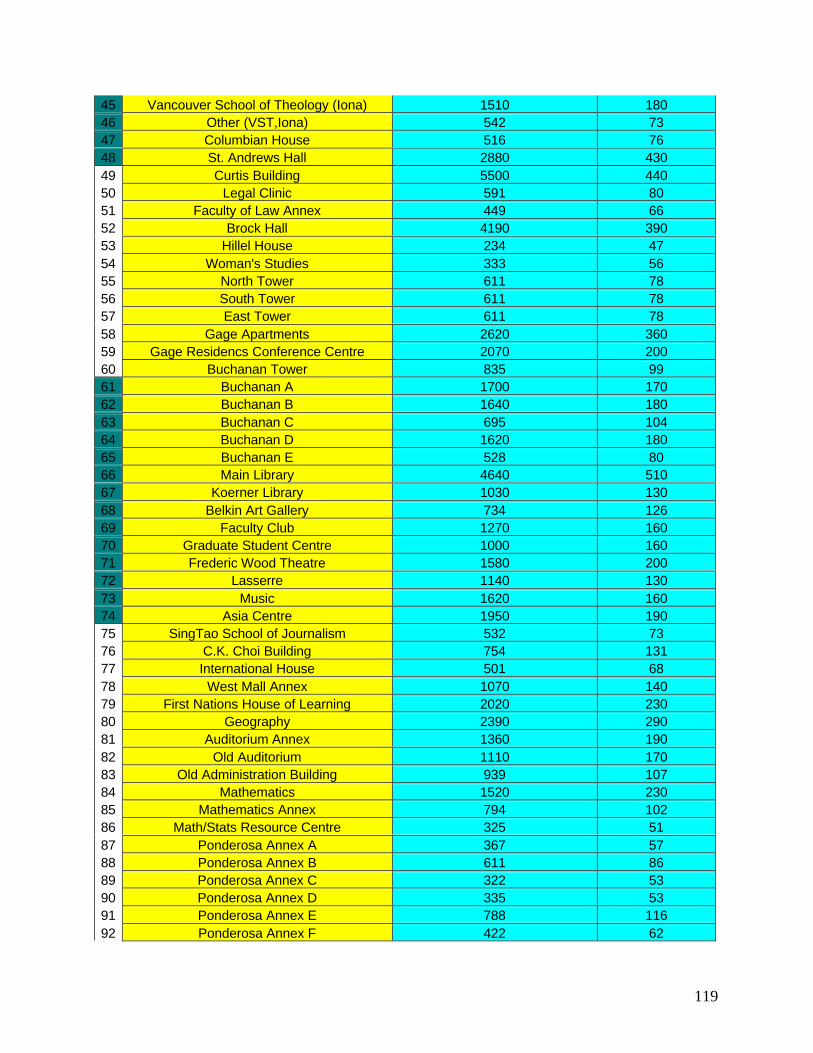
119
45 Vancouver School of Theology (Iona) 1510 18046 Other (VST,Iona) 542 7347 Columbian House 516 7648 St. Andrews Hall 2880 43049 Curtis Building 5500 44050 Legal Clinic 591 8051 Faculty of Law Annex 449 6652 Brock Hall 4190 39053 Hillel House 234 4754 Woman's Studies 333 5655 North Tower 611 7856 South Tower 611 7857 East Tower 611 7858 Gage Apartments 2620 36059 Gage Residencs Conference Centre 2070 20060 Buchanan Tower 835 9961 Buchanan A 1700 17062 Buchanan B 1640 18063 Buchanan C 695 10464 Buchanan D 1620 18065 Buchanan E 528 8066 Main Library 4640 51067 Koerner Library 1030 13068 Belkin Art Gallery 734 12669 Faculty Club 1270 16070 Graduate Student Centre 1000 16071 Frederic Wood Theatre 1580 20072 Lasserre 1140 13073 Music 1620 16074 Asia Centre 1950 19075 SingTao School of Journalism 532 7376 C.K. Choi Building 754 13177 International House 501 6878 West Mall Annex 1070 14079 First Nations House of Learning 2020 23080 Geography 2390 29081 Auditorium Annex 1360 19082 Old Auditorium 1110 17083 Old Administration Building 939 10784 Mathematics 1520 23085 Mathematics Annex 794 10286 Math/Stats Resource Centre 325 5187 Ponderosa Annex A 367 5788 Ponderosa Annex B 611 8689 Ponderosa Annex C 322 5390 Ponderosa Annex D 335 5391 Ponderosa Annex E 788 11692 Ponderosa Annex F 422 62

120
93 Ponderosa Annex G 624 8594 Ponderosa Annex H 771 9695 Ponderosa 1650 16096 Printmaking Hut 651 11297 Old Computer Science Building (LSK) 2320 28098 Power House 1480 21099 Other (Power House) 193 37100 Henry Angus/David Lam Building 5250 600101 Hut M-17/18 2300 210102 Jack Bell Building 702 93103 Botany Annex 307 50104 Arts One 444 80105 Kenny 2880 360106 Scarfe 5030 580107 Campus Planning and Development 748 111108 Plant Operations Annex F 1170 160109 Geolgical Sciences Building 2720 310110 Geophysics and Astronomy Building 1160 180111 Engineering Annex 422 93112 Old Barn Coffee House 234 42113 Forward Building 1140 150114 Coal and Mineral Processing Lab 744 90115 Wood Products Laboratory 572 94116 Horticulture Building/Greenhouse 1780 170117 Plant Sciences Greenhouse 330 57118 Header House 198 37119 MacMillan 3010 430120 Other (MacMillan) 926 107121 Bio-Resource Engineering Annex 324 52122 Thunderbird Residence (west) 4770 600123 Old Barn 323 51124 Thunderbird Residence 2 3070 380125 Pulp & Paper Centre 1390 150126 CICSR/ Computer Science 3140 340127 Advanced Materials 2330 250128 Mcleod Electrical Engineering 1900 230129 Civil & Mechanical Engineering 5770 630130 Civil Engineering/Mechanical Lab 4130 390131 Chemical Engineering 881 114132 Family Nutrition Services 1780 240133 Fisheries Centre 1170 130134 Sustainable Development 1320 180135 Biological Science Building 5970 690136 Bookstore 4360 360137 Chemistry 3970 490138 Physics 1430 180139 Hebb Theatre 1320 200140 Hennigs 3600 310

121
141 Student Union Building (SUB) 6990 530142 Aquatic Centre 2950 290143 War Memorial Gym 3700 310144 Administration Building 2400 260145 Copp 2100 290146 Pharmacology 736 99147 MacDonald 2400 260148 Friedman 1570 220149 Instructional Resources Centre (IRC) 3120 370150 Woodward Library 1940 190151 Wesbrook 3180 400152 Library Processing Centre 1700 250153 Biochemical Research 1030 140154 UBC Hospital 8580 790155 Purdy Pavilion 2240 330156 Detwiller Pavilion 3540 420157 S.E.R.F. Task Force 1750 230158 PE Centre 2550 230159 Osborne Centre 2750 250160 Tennis Courts 2290 220161 Rugby Pavilion 401 59162 Thunderbird Winter Sports Centre 9360 860163 Thames Court 5550 880164 West Hampstead 5270 710165 Sandringham 4980 740166 St. James House 4410 520167 The Chatham 1030 120168 Bristol 4070 470169 Windham Hall 1580 210170 The Stratford 784 94171 The Regency 830 98172 Balmoral 1080 120173 Pemberly 2450 220174 RCMP 1780 290175 Child Care Services Office 2650 550176 Naramata Ct 303 49177 Revelstoke Ct houses 2030 370178 Chilk Study Area 1280 140179 Salmo Ct houses 2030 370180 Oyama Ct houses 1210 220181 Keremeos Ct houses 2030 370182 Melfa Ct houses 1800 330183 Osoyoos Cr. Buildings 6630 710184 Other (Fariview) 458 66185 University Apartments Sopron House 1750 280186 Acadia House 1620 250187 Acadia Highrise 622 119188 Commons 911 109

122
189 Acadia Family Housing 13700 2400190 Fariview Crescent Residence 7320 1040191 Presidents Row Faculty housing 1340 230192 Counselling Psychology 239 42193 Adult Education Research Centre 344 66194 Fraternity Houses 2720 370195 Psychiatric Day House 294 62196 Lutheran Campus Centre 514 102197 Regent College 1690 170
total 387000 47000

123
Appendix II – UBC Rain Data
Time Period Total Rainfall(mm)
Total Rainfall(m)
Total VolumeCollected (m^3)
Error VolumeCollected (m^3)
Total VolumeCollected (L)
Error VolumeCollected (L)
January 147.2 0.1472 56966.4 6918.4 56966400 6918400February 128.1 0.1281 49574.7 6020.7 49574700 6020700
March 116 0.116 44892 5452 44892000 5452000April 81.4 0.0814 31501.8 3825.8 31501800 3825800May 65 0.065 25155 3055 25155000 3055000June 47.9 0.0479 18537.3 2251.3 18537300 2251300July 39.6 0.0396 15325.2 1861.2 15325200 1861200
August 46.4 0.0464 17956.8 2180.8 17956800 2180800September 68 0.068 26316 3196 26316000 3196000
October 132.5 0.1325 51277.5 6227.5 51277500 6227500November 186 0.186 71982 8742 71982000 8742000December 175.7 0.1757 67995.9 8257.9 67995900 8257900
year 1233.8 1.2338 477480.6 57988.6 477480600 57988600Total (rounded) 500 million 60 million
Scaled due torunoff
coefficient of0.8
400 million 48 million

124
Appendix III – Stormwater Pilot Project Pictures
Before Photos
During Photos

125
After Photos

126
Appendix IV – Multiple Account Analysis Tables
Table a. Costs of the Status Quo at a 7% Discount RateSource Cost/Unit Units PV cost 7% Cost to PresentWater GVRD 2002 0.27 5607307736 $1,518,212 $1,518,2122003 0.29 5910102354 $1,615,151 $3,133,3632004 0.32 6229247881 $1,718,279 $4,851,6422005 0.34 6565627266 $1,827,992 $6,679,6342006 0.37 6920171139 $1,944,710 $8,624,3442007 0.40 7030893877 $1,994,291 $10,618,6352008 0.43 7143388179 $2,045,136 $12,663,7712009 0.46 7257682390 $2,097,277 $14,761,0482010 0.50 7373805308 $2,150,748 $16,911,7962011 0.54 7491786193 $2,205,582 $19,117,3792012 0.58 7611654772 $2,261,814 $21,379,1932013 0.63 7733441249 $2,319,480 $23,698,6732014 0.68 7857176309 $2,378,616 $26,077,2892015 0.74 7982891129 $2,439,260 $28,516,5482016 0.80 8110617388 $2,501,449 $31,017,9982017 0.86 8240387266 $2,565,224 $33,583,2222018 0.93 8372233462 $2,630,626 $36,213,8482019 1.00 8506189197 $2,697,694 $38,911,5422020 1.08 8642288225 $2,766,473 $41,678,0152021 1.17 8780564836 $2,837,005 $44,515,0202022 1.26 8921053873 $2,909,336 $47,424,3562023 1.36 9063790735 $2,983,510 $50,407,866Sewage GVRD 2002 0.1963 5019885800 $985,404 $985,4042003 0.1963 5290959633 $970,669 $1,956,0722004 0.1963 5576671453 $956,154 $2,912,2262005 0.1963 5877811712 $941,856 $3,854,0822006 0.1963 6195213544 $927,772 $4,781,8552007 0.1963 6294336961 $880,950 $5,662,8052008 0.1963 6395046352 $836,491 $6,499,2962009 0.1963 6497367094 $794,276 $7,293,5722010 0.1963 6601324968 $754,191 $8,047,7632011 0.1963 6706946167 $716,129 $8,763,8912012 0.1963 6814257306 $679,988 $9,443,8792013 0.1963 6923285423 $645,671 $10,089,5502014 0.1963 7034057989 $613,085 $10,702,6352015 0.1963 7146602917 $582,145 $11,284,7792016 0.1963 7260948564 $552,765 $11,837,5452017 0.1963 7377123741 $524,869 $12,362,4142018 0.1963 7495157721 $498,380 $12,860,7942019 0.1963 7615080244 $473,228 $13,334,0222020 0.1963 7736921528 $449,346 $13,783,3672021 0.1963 7860712273 $426,668 $14,210,0362022 0.1963 7986483669 $405,136 $14,615,171

127
2023 0.1963 8114267408 $384,689 $14,999,861Net Present Cost-20yrs $65,407,727
Table b. Costs of the Rainwater Harvesting Collection System at a 7% Discount RateSources Cost/Unit Units PV cost 7% Cost to PresentTanks 92141 10 $921,413
30714 20 $614,275Filters 2033 30 $61,004System 1000 30 $30,000installation 50 1344 $67,200maintenece 2002 50 240 $12,000 $1,705,8922003 50 240 $11,215 $1,717,1072004 50 240 $10,481 $1,727,5882005 50 240 $9,796 $1,737,3842006 50 240 $9,155 $1,746,5382007 50 240 $8,556 $1,755,0942008 50 240 $7,996 $1,763,0902009 50 240 $7,473 $1,770,5632010 50 240 $6,984 $1,777,5472011 50 240 $6,527 $1,784,0752012 50 240 $6,100 $1,790,1752013 50 240 $5,701 $1,795,8762014 50 240 $5,328 $1,801,2042015 50 240 $4,980 $1,806,1842016 50 240 $4,654 $1,810,8372017 50 240 $4,349 $1,815,1872018 50 240 $4,065 $1,819,2522019 50 240 $3,799 $1,823,0502020 50 240 $3,550 $1,826,6012021 50 240 $3,318 $1,829,9192022 50 240 $3,101 $1,833,0202023 50 240 $2,898 $1,835,918
PV cost 7% PV Savings Savings to PresentWater GVRD2002
0.27 5507307736 $1,491,137 $108,302 $108,302
2003 0.29 5810102354 $1,587,822 $109,315 $217,6172004 0.32 6129247881 $1,690,695 $110,336 $327,9532005 0.34 6465627266 $1,800,150 $111,367 $439,3212006 0.37 6820171139 $1,916,608 $112,408 $551,7292007 0.40 6930893877 $1,965,926 $113,459 $665,1882008 0.43 7043388179 $2,016,506 $114,519 $779,7072009 0.46 7157682390 $2,068,380 $115,589 $895,2962010 0.50 7273805308 $2,121,581 $116,670 $1,011,9662011 0.54 7391786193 $2,176,142 $117,760 $1,129,7262012 0.58 7511654772 $2,232,099 $118,861 $1,248,5862013 0.63 7633441249 $2,289,487 $119,971 $1,368,5582014 0.68 7757176309 $2,348,343 $121,093 $1,489,6502015 0.74 7882891129 $2,408,703 $122,224 $1,611,875

128
2016 0.80 8010617388 $2,470,608 $123,367 $1,735,2412017 0.86 8140387266 $2,534,095 $124,520 $1,859,7612018 0.93 8272233462 $2,599,205 $125,683 $1,985,4442019 1.00 8406189197 $2,665,980 $126,858 $2,112,3022020 1.08 8542288225 $2,734,462 $128,044 $2,240,3462021 1.17 8680564836 $2,804,695 $129,240 $2,369,5862022 1.26 8821053873 $2,876,723 $130,448 $2,500,0342023 1.36 8963790735 $2,950,593 $131,667 $2,631,701
Net Present Cost-20yrs $51,585,859
Table c. Cost of the Wastewater Treatment Pilot FacilitySource Cost /Unit Units PV cost 7% Cost to Presentsystem & 1150000 1 $1,150,000land 375 519 $194,625Storage 92,141 2 $184,282UV treatment 3,087 2 $6,174maintenece 2002 215000 $215,000 $1,559,6252003 215000 $200,935 $1,760,5602004 215000 $187,789 $1,948,3492005 215000 $175,504 $2,123,8532006 215000 $164,022 $2,287,8752007 215000 $153,292 $2,441,1672008 215000 $143,264 $2,584,4312009 215000 $133,891 $2,718,3222010 215000 $125,132 $2,843,4542011 215000 $116,946 $2,960,4002012 215000 $109,295 $3,069,6952013 215000 $102,145 $3,171,8402014 215000 $95,463 $3,267,3032015 215000 $89,217 $3,356,5202016 215000 $83,381 $3,439,9012017 215000 $77,926 $3,517,8272018 215000 $72,828 $3,590,6542019 215000 $68,063 $3,658,7182020 215000 $63,611 $3,722,3292021 215000 $59,449 $3,781,7782022 215000 $55,560 $3,837,3382023 215000 $51,925 $3,889,263
PV cost 7% PV Savings Savings to PresentSewage GVRD 0.1963 5019507259$985,329 $177 $1772003 0.1963 5290581092$970,599 $173 $3502004 0.1963 5576292912$956,089 $169 $5192005 0.1963 5877433171$941,796 $166 $6852006 0.1963 6194835003$927,716 $163 $8482007 0.1963 6293958420$880,897 $160 $1,0082008 0.1963 6394667811$836,442 $158 $1,1662009 0.1963 6496988553$794,229 $156 $1,3222010 0.1963 6600946427$754,147 $154 $1,4762011 0.1963 6706567626$716,088 $152 $1,6282012 0.1963 6813878765$679,950 $150 $1,7782013 0.1963 6922906882$645,635 $149 $1,9272014 0.1963 7033679448$613,052 $148 $2,074

129
2015 0.1963 7146224376$582,114 $147 $2,2212016 0.1963 7260570023$552,736 $146 $2,3662017 0.1963 7376745200$524,842 $145 $2,5112018 0.1963 7494779180$498,355 $144 $2,6552019 0.1963 7614701703$473,205 $144 $2,7992020 0.1963 7736542987$449,324 $143 $2,9422021 0.1963 7860333732$426,648 $143 $3,0852022 0.1963 7986105128$405,116 $143 $3,2272023 0.1963 8113888867$384,672 $143 $3,370
Net Present Cost-20yrs $18,875,349Net Present Cost-20yrs $18,684,893 shared
Table d-The Connected SystemNet Present Cost of Harvesting and Wastewater-20yrs $68,328,579
Net Present Cost of The Status Quo $65,407,727The Rainwater and Wastewater -Status Quo = $2,920,852
Table e-Biofiltration Channel Cost/unit Unit PV Cost 7% Cost to Present
Supplies 5.75 10000 $5,750Plants 20 1000 $20,000Construction 48 2500 $120,000Maintenance 2002 48 52 $2,496 $148,2462003 48 52 $2,333 $150,5792004 48 52 $2,180 $152,7592005 48 52 $2,037 $154,7962006 48 52 $1,904 $156,7002007 48 52 $1,780 $158,4802008 48 52 $1,663 $160,1432009 48 52 $1,554 $161,6982010 48 52 $1,453 $163,1502011 48 52 $1,358 $164,5082012 48 5052 $123,273 $287,7812013 48 52 $1,186 $288,9672014 48 52 $1,108 $290,0752015 48 52 $1,036 $291,1112016 48 52 $968 $292,0792017 48 52 $905 $292,9832018 48 52 $845 $293,8292019 48 52 $790 $294,6192020 48 52 $738 $295,3572021 48 52 $690 $296,0472022 48 5052 $62,666 $358,7132022 48 156 $1,808 $360,522
Net Present Cost $360,522

130
Appendix V – Vancouver And UBC Location Map

131
Glossary
A
Abiotic – non-living environmental factors, including chemical and physical effects.
Aerobic – having oxygen available as an oxidizing agent (electron acceptor).
Anaerobic – not using oxygen as an electron acceptor; the presence of oxygen is detrimental.
Anoxic – oxygen is not present.
B
Biofiltration channel – a modified grass swale proposal by Alpin & Martin to treat stormwater
for quality.
Biophysical – the combination of biological and physical/abiotic processes.
Black water – toilet wastewater.
BMP – Best Management Practices for land developers, managers, etc… to decrease their
environmental impacts.
BOD – Biological Oxygen Demand. The amount of oxygen required to degrade a given amount
of organic matter.
C
Catchment – the amount or water collected from rainfall.
Cistern – a container for the storage of water.
Coagulant – An agent that causes a liquid or colloidal solution to transform into a soft, semisolid,
or solid mass.
Composting tea – the liquid effluent after being broken down in the composting toilets.
Contaminant – a particle/compound/chemical/substance/object that is not naturally present at the
site.
Critical Value – the financial difference between the two options being assessed in a multiple
account analysis. The benefits, from the other account(s) of the more expensive option,
would have to qualitatively be worth at least this amount to the decision maker for the more
expensive option to be feasible.

132
D
Denitrification – the anoxic reduction of nitrate to nitrate to atmospheric nitrogen, resulting in a
loss of nitrogen from the aquatic system. Requires large amounts of organic matter.
Detention – the holding back and containment of water by dams.
Discount Rate – a method for expressing future costs and benefits as present values, so that the
worth of a project to the present decision makers can be assessed. Discounting is used
because money that goes towards a project could have been invested and that investment
could produce returns. Since you forgo the opportunity to invest, you forgo the returns from
that investment.
DO – Dissolved Oxygen (aqueous solution).
Dual Water System – a building which has both potable and non-potable water supplies.
E
Effluent – the treated solution leaving the treatment system.
Emergent (macrophytes) – species that are partially both above and below the water surface.
Eutrophication – the condition that can result after a large increase in organic matter, as the BOD
is dramatically greater than the available oxygen, leading to anaerobic conditions.
Existence Value – The willingness to pay for a good to exist above the willingness to pay for use
of that good. For instance, most people are willing to pay to keep rainforests from
deforestation because the rainforest’s existence is valued in and of itself.
F
Facultative – being able to function efficiently under both aerobic and anaerobic conditions.
Floating (macrophytes) – species whose leaves float on the water surface, while stems and roots
are submerged. May or may not be rooted in bottom sediments.
Flocculation – the process by which small particles come together to for clumps, or flocs.
First Flush – The first rainwater running off roofs, courtyards, or impermeable/semi-permeable
surfaces.

133
G
Grass swale – a grassy ditch to channel stormwater flow.
“Green” – a term used to describe environmentally friendly ideas or technologies (i.e./ green
buildings).
Grey water-Household wastewater not including waste from toilets.
H
Hydrograph – a graphical plot of data comparing discharge vs. time or distance.
I
Influent – the solution entering the treatment system.
Irrigation – the act of transporting and distributing water for the purposes of watering
crops/gardens/etc.
L
Lower Mainland – a term describing the land area of Vancouver and the GVRD in southwestern
BC.
M
Macrophytes – multi-cellular aquatic plants, including various submerged, floating, and aquatic
species.
Marginal Scarcity Rent – The price of being a marginal user of a scarce good or service. A
marginal user is one who purchases small units of a good or service at a price that covers the
cost of producing those units.
N
Nitrification – oxidative processes converting ammonium to nitrite to nitrate, using the bacteria
Nitrosomonas and Nitrobacter (respectively).

134
O
Open channel flow – An enclosed pipe that is less than 100% full of liquid.
Option Value – The willingness to pay for a good because it decreases the risk that you will need
that good in the future and not have it. The good gives you the option to use it in the future,
given that at the present you don’t know what will happen in the future.
Oxic – in the presence of oxygen.
P
Pathogen/pathogenic – an organism that detrimentally affects its host as its sole means of
survival.
PCB – Polychlorinated biphenyl.
Peak Flow – the largest amplitude peak on a hydrograph.
Permeability – the ability of water to penetrate into a medium (such as soil).
Pollutant – a contaminant which exhibits harmful or detrimental effects.
Potable – water that has been classified as safe for human consumption.
Primary Production – the amount of carbon fixed by photosynthetic/autotrophic organisms,
serving as the base of the trophic food chain.
Primary (1°) Treatment – the initial stage of wastewater treatment that removes solid/particulate
matter; the removed solids are known as ‘sludge.’
R
Reclaimed water – wastewater that has been treated and recycled for reuse.
Renovated water – wastewater that has been treated to tertiary standards and is suitable for reuse.
Reservoir – a containment area/facility designed to store large amounts of water before its use.
Rhizosphere – a term referring to the root zone of soil/sediments, physically characterized by the
depth of root activity.
Riparian – vegetation in and alongside a body of water.
Runoff coefficient – The ratio of the volume of water which runs off a surface to the volume of
rain which falls on the surface.

135
S
Salinity – grams of ionic solutes per 1000 grams of water.
Secondary (2°) Treatment – the stage of wastewater treatment that serves to decrease the BOD of
the effluent.
Sludge – the solid residue removed from wastewater during primary treatment.
Sodicity – the amount of exchangeable sodium (Na+) in soils.
Solar Aquatics – a wastewater treatment system utilising aquatic plants within a greenhouse
environment.
Specific Gravity – the relative density of an object compared to that of water (i.e. an object with a
specific gravity of 1.0 is neutrally buoyant in water).
Stormwater – the overland flow and runoff of precipitation.
Submerged (macrophytes) – species that have all physical parts (stems, leaves, etc) below the
water surface.
Sump – a tank which collects the effluent from both the composting toilets and the sinks,
laboratories, and water fountains.
T
Tertiary (3) Treatment – the stage of wastewater treatment that removes excess nutrients
(including N, P) from the effluent.
Trunk Sewer/Main – Main line transport system for sewage or stormwater. Includes largest
volume pipes and channels.
TSS – Total Suspended Solids (in solution).
Turbidity – the degree to which a solution scatters incident light due to suspended particles.
U
Use Value – the willingness to pay for a good or service because you directly consume or
experience it.
UV – the ultraviolet region of the light spectrum.

136
Acronyms
AEES – Advanced Ecological Engineering Systems
BCSDWR – British Columbia Safe Drinking Water Regulation
BMP – Best Management Practice
BOD – Biological Oxygen Demand
CELSS – Closed Ecological Life Support Systems
CFI – Canadian Foundation for Innovation
DIC – Dissolved Inorganic Carbon
DO – Dissolved Oxygen
EDM – Environmental Design and Management Ltd
EEA – Ecological Engineering Associates
EFB – Ecological Fluidized Bed
EPA – Environmental Protection Agency
FREMP – Fraser River Estuary Management Program
GVRD – Greater Vancouver Regional District
GVS&DD – Greater Vancouver Sewage and Drainage District
GVWD – Greater Vancouver Water District
Ha – Alternate Hypothesis
Ho – Null Hypothesis
LWD – Large Woody Debris
MFEMPS – Massachusetts Foundation for Excellence in Marine and Polymer Sciences
N – nitrogen
NASA – National Aeronautics & Space AdministrationNTU – Nephelometric Turbidity UnitsOAI – Ocean Arks InternationalP – phosphorusPCB – Polychlorinated BiphenylsSA – Solar AquaticsSEEDS – Social, Ecological, Economic Development Studies
TCU – True Colour Units
TSS – Total Suspended Sediment
UBC – the University of British Columbia; located in Vancouver, BC, Canada.
US – United States
UV – Ultraviolet
WHO – World Health Organisation
WWTP – Waste Water Treatment Plant