water injected screw compressor
TRANSCRIPT

NUMERICAL INVESTIGATION OF HEAT TRANSFER ON SCREW COMPRESSOR ROTORS
N Stosic, I. K. Smith and A. KovacevicCentre for Positive Displacement Compressor Technology,
City University, London EC1V OHB, U.K, e-mail: [email protected]
Key words: Heat Transfer, Dry Screw Compressor, Water Injection
Abstract. Since dry screw compressor rotors and housing are subjected to high temperatures which cause their deformation, they either may not operate at high pressure ratio, or they must be cooled. However, the gas temperature is high only in the high pressure region of the screw compressor therefore the domain where the heat is transferred to the rotors is limited to only a small portion of the rotors and housing. Also, since the rotors revolve at high speeds while residing only briefly within areas of different gas temperatures during one cycle, the rotor temperature becomes virtually uniform across any cross sectional area perpendicular to the rotor axis and its value is somewhere between the highest and lowest gas temperature at that cross section area. At the same time, due to the relatively high thermal conductivity of the compressor components, which are made of metal, heat transfer by conduction is considered substantial and the rotor body temperature attained is a result of a balance between the heat received from the gas and its dissipation in regions of lower gas temperature. Consequently, it appears that rotor cooling is required only in the compressor high temperature region to keep rotor temperatures at a reasonable level.
Therefore, an effective means of cooling the rotors could be to inject a small quantity of flashing liquid, preferably water into the casing, at the high pressure port end in any circumferential position. The liquid would then impinge on the rotors at a rate such that it would be instantly evaporated by contact with them. To confirm these principles and quantify the heat transfer rate and required flow rate of liquid injected for rotor cooling, a complex numerical investigation by using a CFD code has been performed. The results indicate that dry compressors may run at pressure ratio up to 8:1. This is substantially higher than the normal pressure ratios attainable in such machines. It is also shown that due to the high rotational speed and intermittent passing through hot and cold gas areas, the rotor temperature is far lower than that of the gas. Since the heat transfer rate between the gas and the rotors is very low, it is possible to cool the rotors by only relatively small quantities of flashing fluid, such as water. The experimental investigation was performed to confirm these estimations. The result of this investigation is that only minor modification is required for oil free compressors to be made to operate with much higher pressure ratios in a single stage.
1123
NOMENCLATURE
c - concentrationf - body forceh - enthalpym - mass q - heat fluxp - pressures - control volume surfaces - source/sink
S - strain tensort - timeT - stress tensorT - temperaturev - velocityV - volumex - spatial coordinate - density
1 INTRODUCTIONThe present world annual production rate of positive displacement compressors is in excess
of 200 million units, while approximately 17% of the world’s electric power production is required to drive them in industrial, commercial and domestic applications. The majority of these are reciprocating machines but many other types, such as screw compressors, play a significant role.
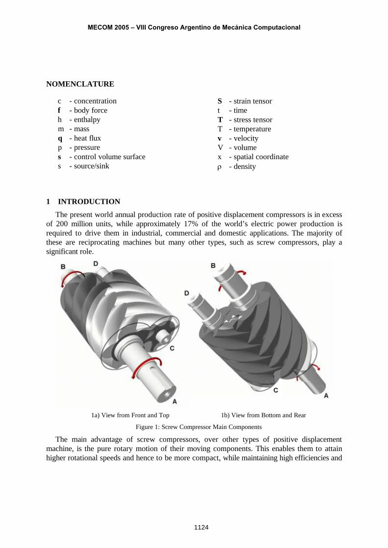
1a) View from Front and Top 1b) View from Bottom and Rear
Figure 1: Screw Compressor Main Components
The main advantage of screw compressors, over other types of positive displacement machine, is the pure rotary motion of their moving components. This enables them to attain higher rotational speeds and hence to be more compact, while maintaining high efficiencies and
MECOM 2005 – VIII Congreso Argentino de Mecánica Computacional
1124
delivery rates over a wide range of operating conditions with less wear and hence a longer service life. Thus, typically, they are up to five times lighter than reciprocating compressors of the same capacity and their service life is nearly ten times longer. Consequently an increasing proportion of positive displacement compressors sold and currently in operation are of this type.
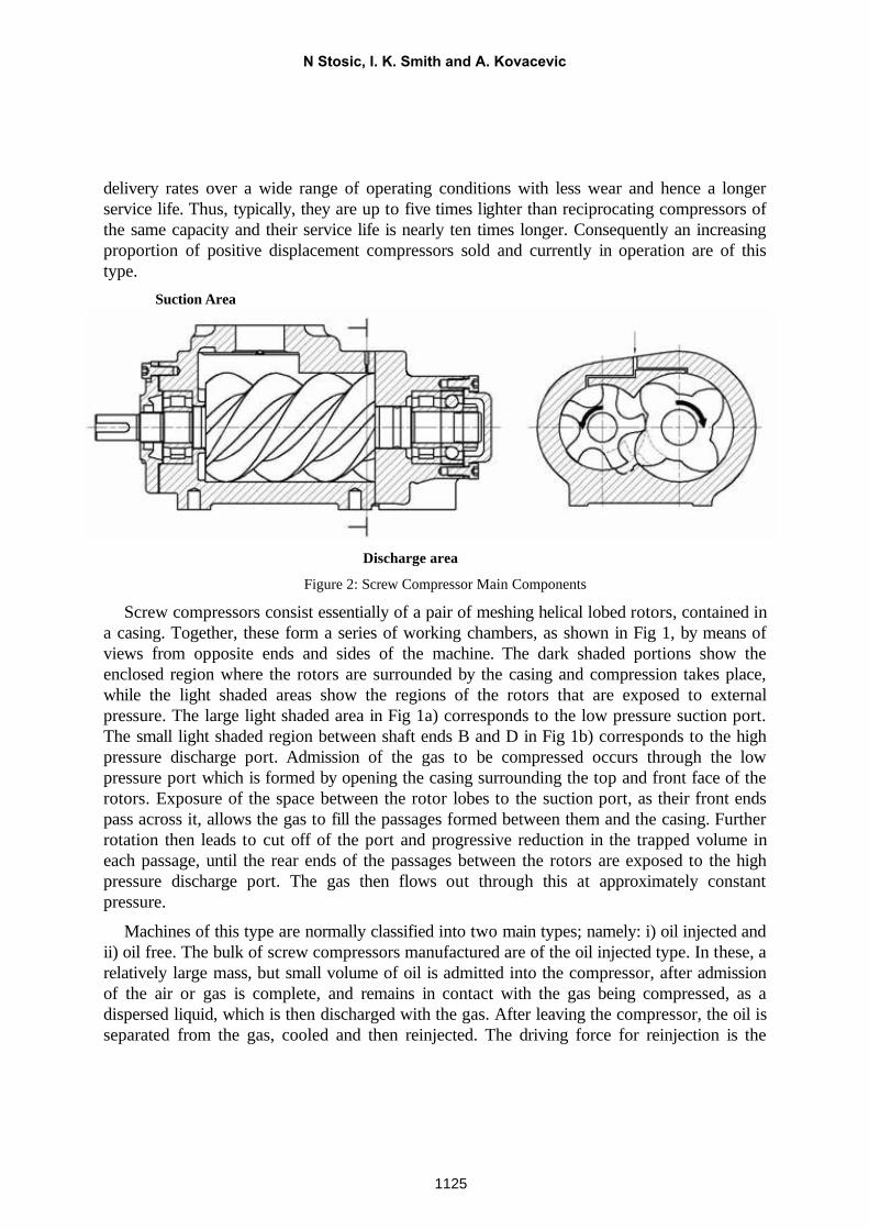
Suction Area
Discharge area
Figure 2: Screw Compressor Main Components
Screw compressors consist essentially of a pair of meshing helical lobed rotors, contained in a casing. Together, these form a series of working chambers, as shown in Fig 1, by means of views from opposite ends and sides of the machine. The dark shaded portions show the enclosed region where the rotors are surrounded by the casing and compression takes place, while the light shaded areas show the regions of the rotors that are exposed to external pressure. The large light shaded area in Fig 1a) corresponds to the low pressure suction port. The small light shaded region between shaft ends B and D in Fig 1b) corresponds to the high pressure discharge port. Admission of the gas to be compressed occurs through the low pressure port which is formed by opening the casing surrounding the top and front face of the rotors. Exposure of the space between the rotor lobes to the suction port, as their front ends pass across it, allows the gas to fill the passages formed between them and the casing. Further rotation then leads to cut off of the port and progressive reduction in the trapped volume in each passage, until the rear ends of the passages between the rotors are exposed to the high pressure discharge port. The gas then flows out through this at approximately constant pressure.
Machines of this type are normally classified into two main types; namely: i) oil injected and ii) oil free. The bulk of screw compressors manufactured are of the oil injected type. In these, a relatively large mass, but small volume of oil is admitted into the compressor, after admission of the air or gas is complete, and remains in contact with the gas being compressed, as a dispersed liquid, which is then discharged with the gas. After leaving the compressor, the oil is separated from the gas, cooled and then reinjected. The driving force for reinjection is the
N Stosic, I. K. Smith and A. Kovacevic
1125
pressure difference between the discharged gas and that between the meshing rotors, trapped in the compressor immediately after suction is complete. The oil serves three purposes; namely as a lubricant, as a sealant of the clearances between the rotors and between the rotors and the casing and as a coolant of the gas being compressed. Because of this latter effect, gases can be compressed to pressure ratios of up to about 15:1 in a single stage without an excessive temperature rise.
Dry gas compression in screw machines is limited to a pressure ratio of approximately 3:1. This is because the higher gas temperatures of the uncooled gas cause the rotors and housings to deform. It follows that if the rotors were cooled, higher pressure ratios would be possible. To do this effectively, the principles of heat transfer within these machines needs to be properly understood.
2 HEAT TRANSFER WITHIN SCREW COMPRESSORFirstly, it must be appreciated that the gas temperature is only high in the high pressure
region of the screw compressor. This occurs where the working chamber volume is greatly compressed. This is in the region of the compressor, immediately prior to the discharge port, as shown at the location marked as the ‘discharge area’ in Fig 2. Consequently, the area enclosing this volume, from which heat is transferred to the compressor components, is small. Also, the heat transfer coefficient between the gas and the rotors is low. Thus Brok et al, 1980 [1] claim that the heat transfer between gas and compressor elements is negligible. Recktenwald et al, 1986 [4] disagree but still admit that, in energy terms, the heat transfer rate is less than one percent of the total compressor power input. Nevertheless, over a large number of compression cycles, resulting from continuous operation, the temperature rise within the compressor parts can be substantial.
Secondly, the gas temperature varies significantly around the circumference of the compressor bore in any plane normal to the axis of rotor rotation, especially near the discharge port where the pressure varies between near suction and discharge. Despite this, due to the rapid rotation of the rotors and the poor rate of heat transfer between the gas and the rotors, the rotor temperature is almost constant around the circumference. However, the compressor components are made of metal, which has a relatively high thermal conductivity. It follows that the main means of heat transfer along the length of the rotors from the high pressure to the low pressure ends is by internal conduction along them with an approximately linear body temperature distribution in the axial direction. The rotor temperatures attained are therefore the result of a balance between the heat received from the gas at high temperature and its rejection to regions at lower temperature.
When these considerations are taken into account, an effective means of cooling the rotors could be to inject a small quantity of flashing liquid, preferably water into the casing, at the axial end corresponding to that of the high pressure port in any circumferential position. The liquid would then impinge on the rotors at a rate such that, due to the high heat transfer
MECOM 2005 – VIII Congreso Argentino de Mecánica Computacional
1126
coefficient it would instantly evaporate on contact with them. In view of the low heat transfer rate from the gas to the rotors, the liquid mass flow rate required for this would be of the order of only a few tenths of one percent of the mass flow rate of the gas being compressed. The liquid would then separate out from the compressed gas by condensation in the compressor aftercooler, which is a common component of a dry compressor plant.
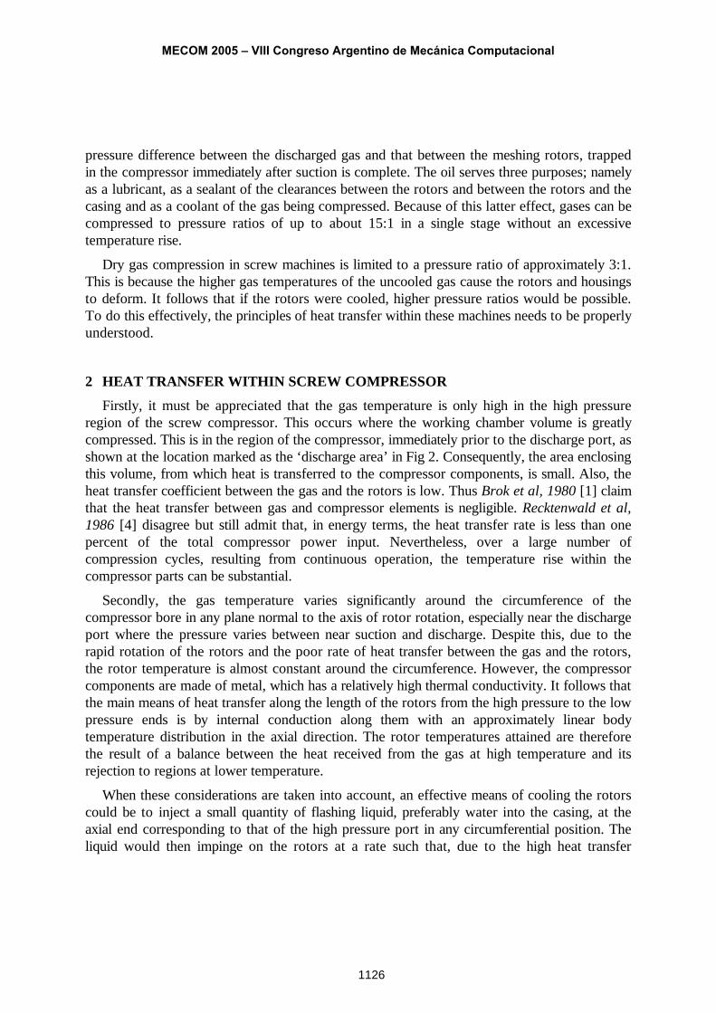
Figure 3: Screw compressor pressure and temperatures
To confirm these principles and quantify the heat transfer rate and required flow rate of liquid injection for rotor cooling, an initial study of heat and fluid flow in a screw compressor was carried out using a computer code, based on the assumption of homogenous on one dimensional flow of fluid through the compressor, details of which are given by Hanjalic and
N Stosic, I. K. Smith and A. Kovacevic
1127
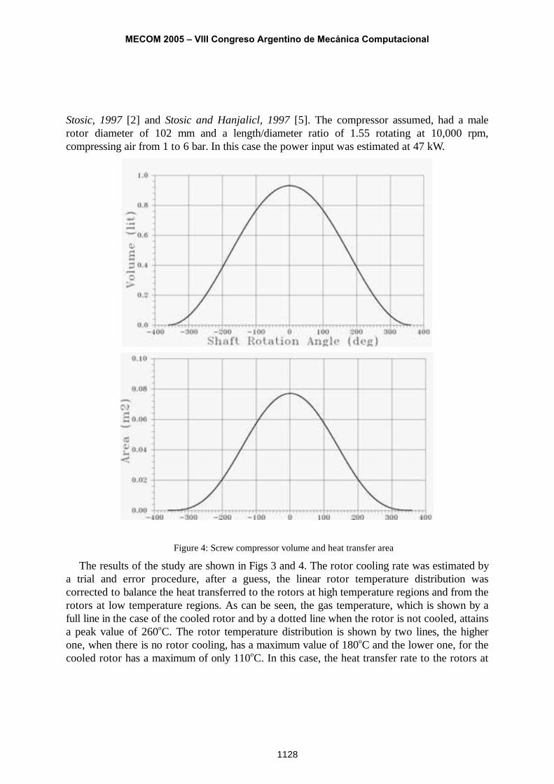
Stosic, 1997 [2] and Stosic and Hanjalicl, 1997 [5]. The compressor assumed, had a male rotor diameter of 102 mm and a length/diameter ratio of 1.55 rotating at 10,000 rpm, compressing air from 1 to 6 bar. In this case the power input was estimated at 47 kW.
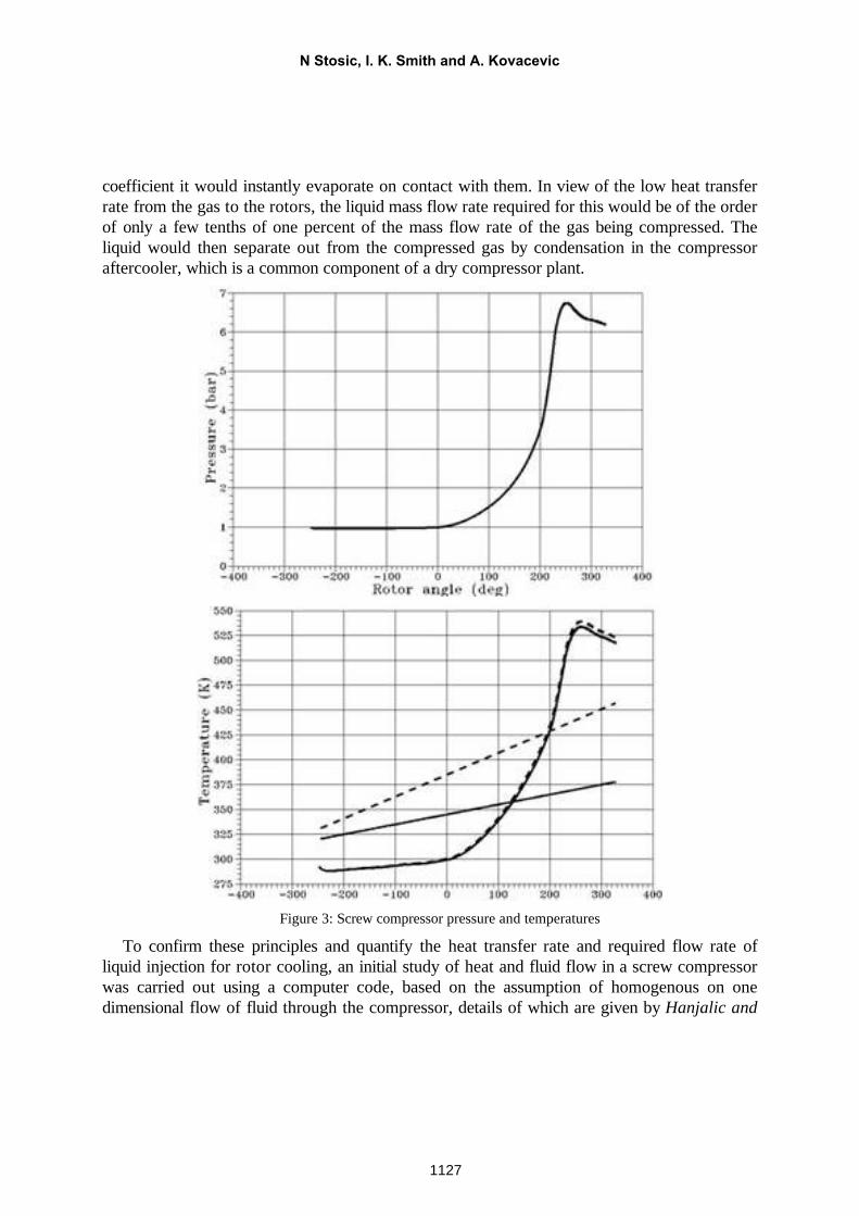
Figure 4: Screw compressor volume and heat transfer area
The results of the study are shown in Figs 3 and 4. The rotor cooling rate was estimated by a trial and error procedure, after a guess, the linear rotor temperature distribution was corrected to balance the heat transferred to the rotors at high temperature regions and from the rotors at low temperature regions. As can be seen, the gas temperature, which is shown by a full line in the case of the cooled rotor and by a dotted line when the rotor is not cooled, attains a peak value of 260oC. The rotor temperature distribution is shown by two lines, the higher one, when there is no rotor cooling, has a maximum value of 180oC and the lower one, for the cooled rotor has a maximum of only 110oC. In this case, the heat transfer rate to the rotors at
MECOM 2005 – VIII Congreso Argentino de Mecánica Computacional
1128
the high temperature region was estimated as only about 100 W and about 1/3 of the heattransferred to the rotors was removed by the water jet impinging on the high temperature area of the rotor.
For the calculated conditions, the water flow was 0.0132 g/s, while the air flow was 0.184 kg/s, giving the mass ratio of water injected against the air flow of 72 ppm. This is well within the region of humid but not wet air and implies that the injected water evaporated completely, using its latent heat to cool the rotors. Under these circumstances, the liquid can be recovered from the compressed gas after cooling in the compressor aftercooler, which is a common element of dry compressor plant. It should be noted that the water injection rate is so small that the rotor cooling hardly affected the gas discharge temperature.
These results show that by the use of such a simple cooling procedure, oil free compressors can be built to operate with much higher pressure ratios in a single stage.
The cost of their manufacture for high pressure applications would thereby be reduced and their efficiencies increased. It would also thereby be possible to use twin screw machines to expand gases at much higher temperatures than is presently thought to be possible. It is concluded that by the use of this technique, only minor design changes are needed to enable oil free compressors to operate with much higher stage pressure ratios.
.
3 3-D NUMERICAL STUDY OF A SCREW COMPRESSOR HEAT TRANSFERContemporary developments in computational fluid dynamics and heat transfer enable the
flow processes within screw compressors to be estimated, taking full account of 3-D effects. Numerical calculation of the heat and fluid flow through them by this means, improves the understanding of the flow phenomena and enables the maximum possible improvements to be made to the machine design. An independent stand-alone interface program, which connects the screw compressor geometry and a CFD preprocessor, has been developed by the authors in order to generate a numerical grid for this purpose.
The interface employs a procedure to produce rotor profiles and an analytical transfinite interpolation method with adaptive meshing to obtain a fully structured 3-D numerical mesh, which is directly transferable to a CFD code. This was required to overcome problems associated with moving, stretching and sliding rotor domains and with robust calculations in domains with significantly different geometry ranges.
Some changes have been made within the solver functions both to enable calculations and to make them faster. These include a means to maintain constant pressures at the inlet and outlet ports and consideration of two-phase flow resulting from oil injection in the working chamber. Modifications implemented to the CFD procedure improved solutions in complex domains with strong pressure gradients.
The pre-processor code and calculating method have been tested on a commercial CFD solver to obtain flow simulations and integral parameter calculations. More information on the
N Stosic, I. K. Smith and A. Kovacevic
1129
screw compressor CFD is given by Kovacevic et al 2003 [3]. The program interface calculates the meshing rotor coordinates from given rack or rotor curves, by means of two parameter adaptation, and then calculates the grids for both rotors. It also calculates the grids for the inlet and outlet ports and prepares the control parameters necessary for the CFD calculation of the compressor fluid flow.
The compressor flow is fully described by the mass averaged equations of continuity, momentum and energy conservation, which are accompanied by the turbulence model equations and an equation of state. Equations are given for the control volume V bounded by surface s in the integral form similar for all conserved properties. They all contain local and convective rates of change on the left hand side and diffusive and source terms on the right hand side.
The continuity equation is:
s( ) 0V S
d dV ddt
v v s ,
where is the density and v is the fluid velocity, while vs is the grid velocity.
The momentum equation is:
s( ) bV S S V
d dV d d dVdt
v v v v s T s f
where T is a stress tensor, and fb is the resultant body force.
Since liquid is injected into a screw compressor, the oil concentration ii
mcm
, where m is
the overall mass, is calculated from its equation as a passive component, which affects the air in the source term of the mass and enthalpy equation. The concentration equation is:
s( )i i ci ciV S S V
d c dV c d d s dVdt
v v s q s
qci and sci denote the diffusion flux and source or sink of liquid.
The transport equation of enthalpy is:
s
s
( )
: p
h hV S S V
V V S V
d hdV h d d s dVdt
ddV p dV d pdVdt
v v s q s
S v v v s
where S is the viscous part of the stress tensor, p is pressure, qh is the heat flux and sh
represents the heat source or sink.
MECOM 2005 – VIII Congreso Argentino de Mecánica Computacional
1130
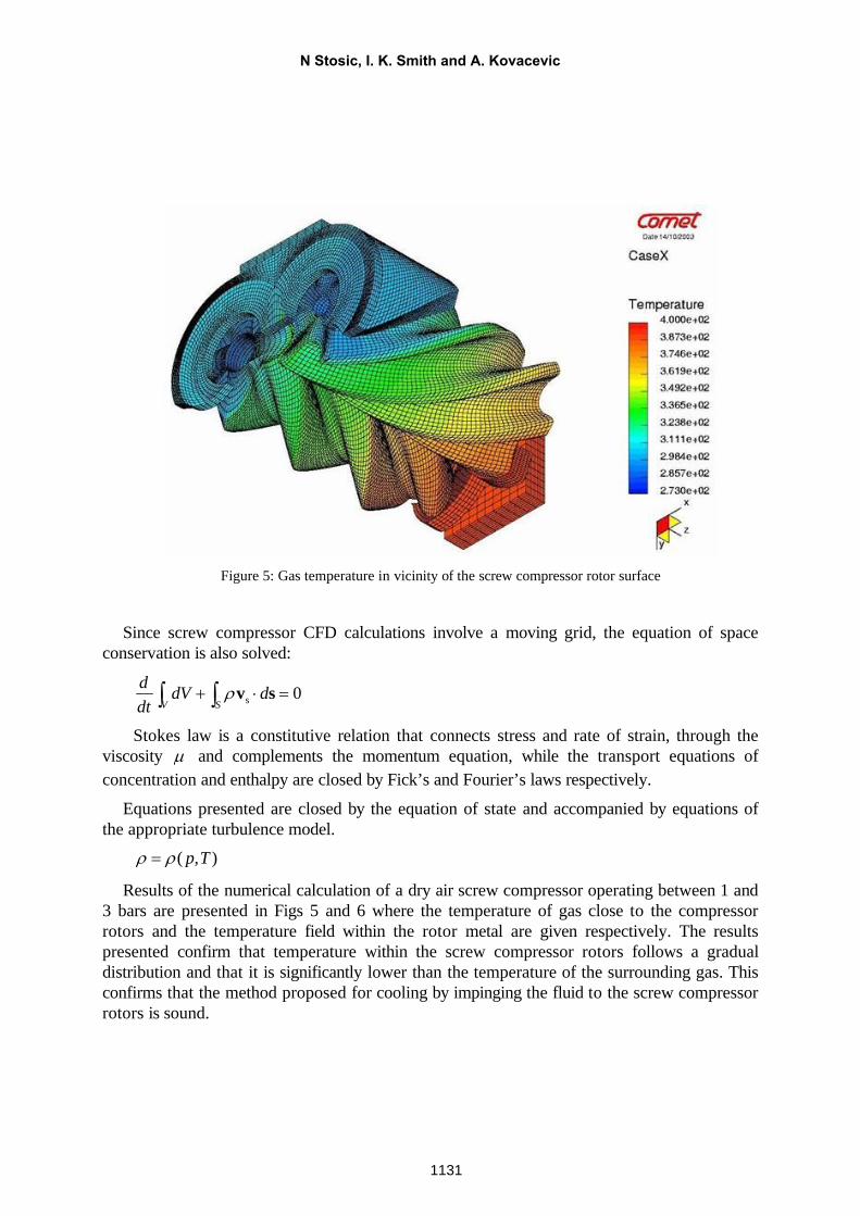
Figure 5: Gas temperature in vicinity of the screw compressor rotor surface
Since screw compressor CFD calculations involve a moving grid, the equation of space conservation is also solved:
s 0V S
d dV ddt
v s
Stokes law is a constitutive relation that connects stress and rate of strain, through the viscosity and complements the momentum equation, while the transport equations of concentration and enthalpy are closed by Fick’s and Fourier’s laws respectively.
Equations presented are closed by the equation of state and accompanied by equations of the appropriate turbulence model.
( , )p T
Results of the numerical calculation of a dry air screw compressor operating between 1 and 3 bars are presented in Figs 5 and 6 where the temperature of gas close to the compressor rotors and the temperature field within the rotor metal are given respectively. The results presented confirm that temperature within the screw compressor rotors follows a gradual distribution and that it is significantly lower than the temperature of the surrounding gas. This confirms that the method proposed for cooling by impinging the fluid to the screw compressor rotors is sound.
N Stosic, I. K. Smith and A. Kovacevic
1131
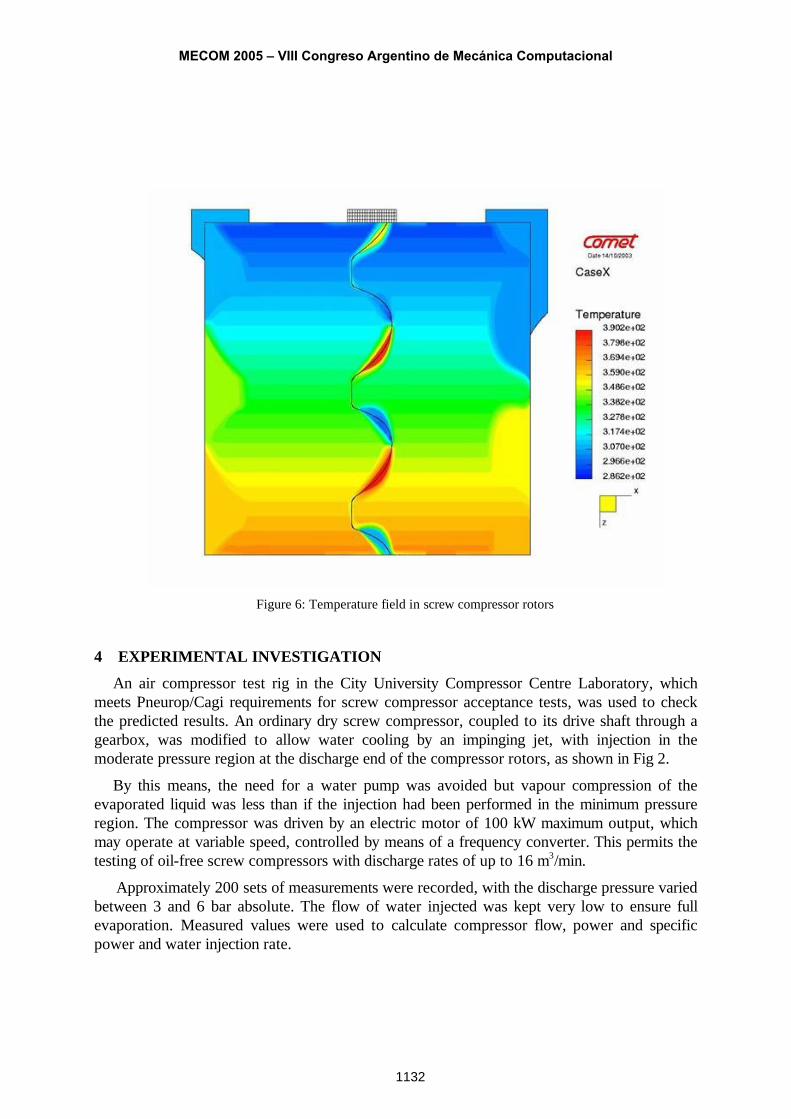
Figure 6: Temperature field in screw compressor rotors
4 EXPERIMENTAL INVESTIGATIONAn air compressor test rig in the City University Compressor Centre Laboratory, which
meets Pneurop/Cagi requirements for screw compressor acceptance tests, was used to check the predicted results. An ordinary dry screw compressor, coupled to its drive shaft through a gearbox, was modified to allow water cooling by an impinging jet, with injection in the moderate pressure region at the discharge end of the compressor rotors, as shown in Fig 2.
By this means, the need for a water pump was avoided but vapour compression of the evaporated liquid was less than if the injection had been performed in the minimum pressure region. The compressor was driven by an electric motor of 100 kW maximum output, which may operate at variable speed, controlled by means of a frequency converter. This permits the testing of oil-free screw compressors with discharge rates of up to 16 m3/min.
Approximately 200 sets of measurements were recorded, with the discharge pressure varied between 3 and 6 bar absolute. The flow of water injected was kept very low to ensure full evaporation. Measured values were used to calculate compressor flow, power and specific power and water injection rate.
MECOM 2005 – VIII Congreso Argentino de Mecánica Computacional
1132
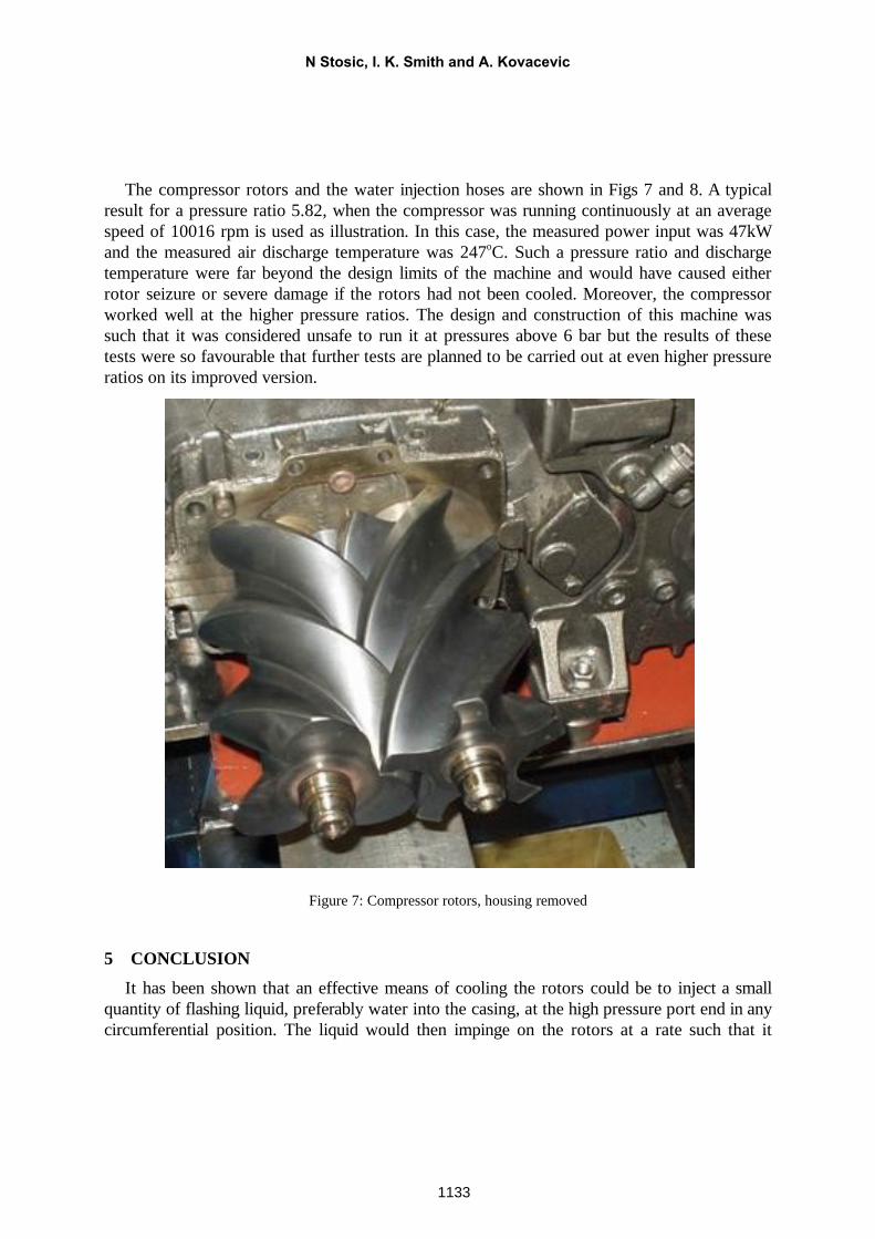
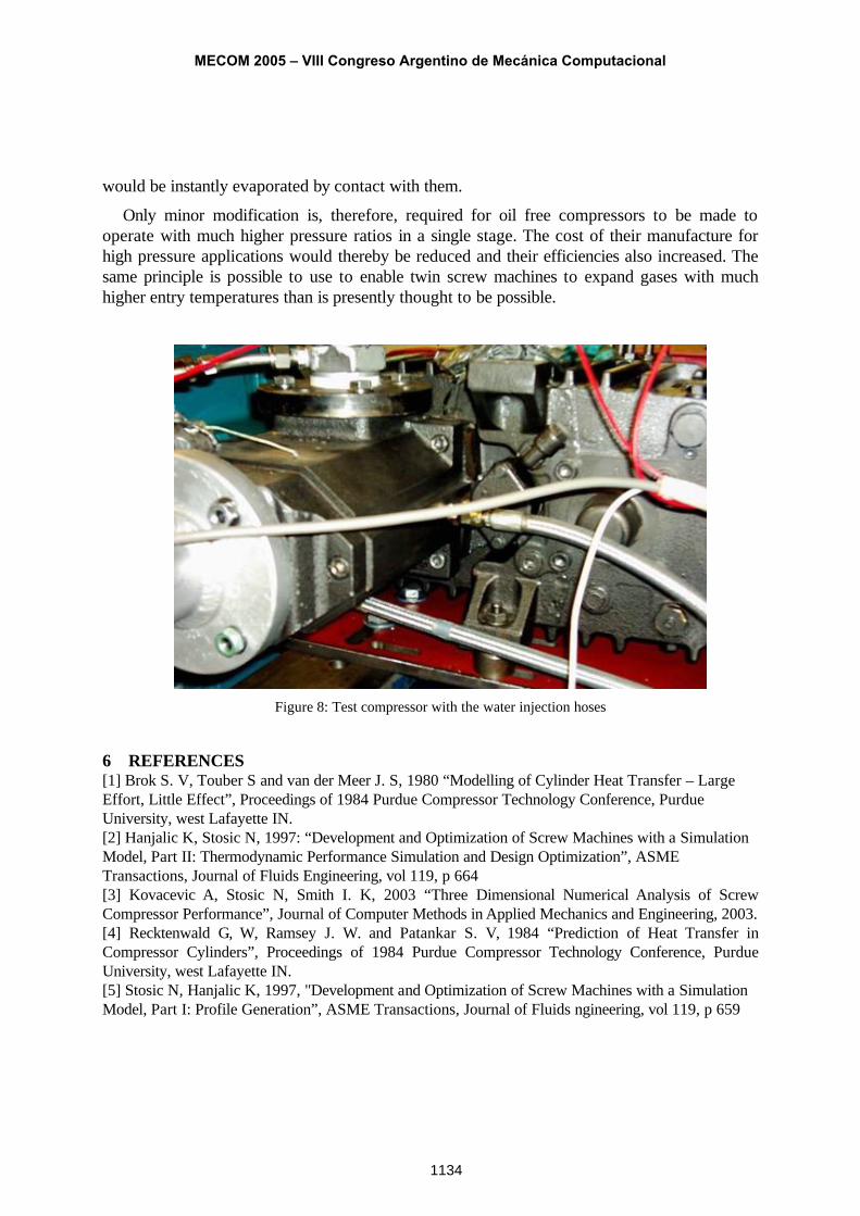
The compressor rotors and the water injection hoses are shown in Figs 7 and 8. A typical result for a pressure ratio 5.82, when the compressor was running continuously at an average speed of 10016 rpm is used as illustration. In this case, the measured power input was 47kW and the measured air discharge temperature was 247oC. Such a pressure ratio and discharge temperature were far beyond the design limits of the machine and would have caused either rotor seizure or severe damage if the rotors had not been cooled. Moreover, the compressor worked well at the higher pressure ratios. The design and construction of this machine was such that it was considered unsafe to run it at pressures above 6 bar but the results of these tests were so favourable that further tests are planned to be carried out at even higher pressure ratios on its improved version.
Figure 7: Compressor rotors, housing removed
5 CONCLUSIONIt has been shown that an effective means of cooling the rotors could be to inject a small
quantity of flashing liquid, preferably water into the casing, at the high pressure port end in any circumferential position. The liquid would then impinge on the rotors at a rate such that it
N Stosic, I. K. Smith and A. Kovacevic
1133
would be instantly evaporated by contact with them.
Only minor modification is, therefore, required for oil free compressors to be made to operate with much higher pressure ratios in a single stage. The cost of their manufacture for high pressure applications would thereby be reduced and their efficiencies also increased. The same principle is possible to use to enable twin screw machines to expand gases with much higher entry temperatures than is presently thought to be possible.
Figure 8: Test compressor with the water injection hoses
6 REFERENCES[1] Brok S. V, Touber S and van der Meer J. S, 1980 “Modelling of Cylinder Heat Transfer – Large Effort, Little Effect”, Proceedings of 1984 Purdue Compressor Technology Conference, Purdue University, west Lafayette IN.[2] Hanjalic K, Stosic N, 1997: “Development and Optimization of Screw Machines with a Simulation Model, Part II: Thermodynamic Performance Simulation and Design Optimization”, ASME Transactions, Journal of Fluids Engineering, vol 119, p 664[3] Kovacevic A, Stosic N, Smith I. K, 2003 “Three Dimensional Numerical Analysis of Screw Compressor Performance”, Journal of Computer Methods in Applied Mechanics and Engineering, 2003.[4] Recktenwald G, W, Ramsey J. W. and Patankar S. V, 1984 “Prediction of Heat Transfer in Compressor Cylinders”, Proceedings of 1984 Purdue Compressor Technology Conference, Purdue University, west Lafayette IN. [5] Stosic N, Hanjalic K, 1997, "Development and Optimization of Screw Machines with a Simulation Model, Part I: Profile Generation”, ASME Transactions, Journal of Fluids ngineering, vol 119, p 659
MECOM 2005 – VIII Congreso Argentino de Mecánica Computacional
1134