waste-free beer filtration with ceramic membranes · waste-free beer filtration with ceramic...
TRANSCRIPT

Waste-free beer filtration with ceramic membranes
A white paper on GEA clearamic BeerFiltration

AUTHORS: SONJA VON LIERES, FELIX OCKERT, KORNEL VETTERLEIN
2 · GEA CLEARAMIC BEERFILTRATION

1. Introduction 4
2. Basic principles of beer filtration 6
2.1 Static deep-bed filtration 6
2.2 Precoat filtration 6
2.3 Cross-flow filtration with membranes 7
2.3.1 Durable ceramic membranes 8
2.3.2 Manufacture and characteristics of ceramic membranes 10
3. System layout for beer filtration with cross-flow filtration 12
4. Use of ceramic membranes in cross-flow filtration 15
4.1 Work sequence of cross-flow filtration 15
4.2 Exploitation of the remaining retentate 15
4.3 Cleaning sequence 15
4.4 Protecting against membrane breakage 15
4.5 Modular block 15
5. Product result 16
6. Costs 16
7. Summary 17
GEA: proven partner to the brewing industry 18
Table of contents
GEA CLEARAMIC BEERFILTRATION · 3

1. Introduction
Sustainability is now a universal process criterion. The brewing industry
too is intensively concerned with optimizing the consumption of natural
resources and launching “green” products, which represent a high level of
ecological responsibility. As well as changed legal constraints and image
cultivation, cost concerns also play a substantial role here.
The procurement, handling and disposal of filter aids have become e. g. a
cost factor that increasingly impairs the profitability of breweries. At the same
time, the consumer also still expects a brilliantly clear product of consistent
quality.
In this situation GEA clearamic BeerFiltration is the timely solution: as a
wastefree beer filtration, this process works with absolutely no filter aids at
the same time as ensuring genuine, unadulterated beer enjoyment.
The ceramic membranes form the centrepiece of this cross-flow filtration.
The material is absolutely foodneutral and can be regenerated again at any
time in the filtration system. The service life of the membrane is at least 10
years. The result: purest beer quality – brewed in a way that is sustainable
and reduces costs.
The following report considers the technical-technological background and
explains the basic principles and features of the filtration process.
4 · GEA CLEARAMIC BEERFILTRATION

1. Introduction
GEA CLEARAMIC BEERFILTRATION · 5

2. Basic principles of beer filtration
Beer filtration must always be seen in conjunction with stabiliza-
tion, as adequate turbidity and stability cannot be ensured with
filtration only. Stabilization takes place before, during or after
the actual filtration. Filtered beer becomes cloudy again shortly
after filtration.
The reaction of the colloidal and genuinely dissolved substances
– with the aid of movement, light, temperature fluctuations and
time – results in the formation of larger colloids. Initially, these
form opal turbidity and might ultimately emerge as flakes.
This is slowed down by reducing or completely removing the
reactants. Known stabilizing agents are polyvinylpolypyrrolidone
(PVPP), silica gel and kieselsol as well as various enzymes and
tannin outside of the purity law. Deep-bed, precoat and cross-
flow filtration with membranes are used for filtering beverages.
The first of these use filter aids such as cotton or cellulose fibers
or kieselguhr and perlite as powder, the effectiveness of which is
further improved with the addition of other substances such as
silica gel or previously asbestos.
Generally, filter aids can produce pure separation, like a sieve;
however, they can also work adsorptively and accumulate solids.
Essentially, the procedures used can be summarized
in three groups:
2.1 Static deep-bed filtration
The cloudy product flows through a porous filter cake, which
retains the solids. Depending on size and nature, these are
deposited on the cake or in the pores of the cake. Ready-made
filter layers with a thickness of approx. 10 mm are established,
which consist of cellulose and kieselguhr.
Classic beer filtration – mass filtration – was carried out with
cotton mass. Even though it was nearly waste- free it required
large quantities of washing water, manpower and energy and
was therefore superseded by kieselguhr filtration.
Static deep-bed filtration is nowadays used only rarely as the
sole filtration. However, with layer filters, it is common and
established as a safety filtration following another filtration.
2.2 Precoat filtration
The most common type is the filtration with kieselguhr as
filter aid. Due to this many process steps have been adapted to
the filtration.
The coarse kieselguhr (or perlite) is washed up on a supporting
layer, e.g. coarse filter layer or metal sieve, and bridges the pores
of the supporting layer. Another deposit of fine kieselguhr comes
onto this first sedimentation that leads to a greater filtration
intensity. Beer is now pumped onto the filter and clarified.
The active mechanisms here are both the sieve effect and adsorp-
tion. A constant dosage of kieselguhr into the unfiltered beer
prevents blocking of the cake surface by the solids. The filter
cake grows over the duration of filtration and thus remains
porous. With the addition of silica gel, proteins can be accumu-
lated at the same time, which prevents a subsequent clouding
reaction in the beer. With a variety of kieselguhr, other aids such
as PVPP and various dosage quantities, a highly flexible and
established system has been created. Time consuming is the
treatment of the kieselguhr before and after filtration. The dis-
posal of used kieselguhr is becoming increasingly difficult.
Moreover, there is discussion of the transfer of substances from
the kieselguhr into the beer.
6 · GEA CLEARAMIC BEERFILTRATION

From the present perspective, the resources can be considered
unlimited. Kieselguhr filtration can withstand greater
quantities of solids than e. g. mass filtration, yet preliminary
clarification or young beer separators have become accepted
everywhere since the introduction of CCTs (cylindro-conical
tanks). The current processes for beer stabilization are
entirely geared towards kieselguhr filtration and take place
on its periphery.
2.3 Cross-flow filtration with membranes
By contrast with kieselguhr filtration, membrane filtration is
largely a surface filtration.
Solids are retained on or in the pores of the membrane.
With a flow over the membrane surface at right angles to
the filtration direction, these solids are washed away again
and held in suspension, so the membrane surface remains
clear and therefore active. This cross-flow is achieved by high
circulatory pumping capacities within the system, cf. fig. 1.
The membranes slowly become blocked due to the
cross-flow then have to be chemically cleaned. This is
time-consuming as the membrane can also become
blocked at depth. Contamination that has settled here is
difficult for cleaning agents to reach and can be removed
only slowly and under aggressive conditions.
Fig. 1: Unfiltrate passes
through the channels of the
membrane: a partial stream
passes through the membrane
as filtrate (2) whereas the
retentate (1) continues to flow
1 ~ 2000 mm/s2 ~ 0.5 mm/s
GEA CLEARAMIC BEERFILTRATION · 7

Polymer membranes are temperature resistant only to a limited
extent and therefore destroyed by cleaning in the medium term.
As they consist of organic material, they are not completely
inert. There is always a need for membrane replacement which
may even be required annually depending on the CIP (cleaning
in place) intervals and operating hours. Ceramic membranes
are more expensive to purchase but when optimally installed
virtually indestructible.
Durabilities of well over ten years are common in practice.
Moreover, they are a completely inert and therefore food-com-
patible medium.
2.3.1 Durable ceramic membranes
Advantages of ceramic membranes in cross-flow filtration:
• Completely inert material
• Free to choose the right pore size for an optimum filtration
• Operationally safe
• Long lifetime of more than 10 years
• High temperature range (135 °C), can be sterilized with steam
• High mechanical stability
• Very good cleanability
• Full pH range 0 – 14
• Standard cleaning agents: NaOH, HNO3 and booster
• Cleaning times approx. 2.5 h
• Acid and base resistant, solvent resistant
• Can be regenerated
• No problems with back flushing
• Wear resistant
• Robust against pressure and temperature
• Constant flux rate of filtrate over the complete lifetime cycle
• Minimum operational costs
• Short installation and start-up times, due to pre-assembling
Membrane filter
Filtrate
Retentate
Highly porous ceramic body
Fig. 2: With cross-flow,
part of the volume
passes through the
membrane and is
discharged as filtrate
8 · GEA CLEARAMIC BEERFILTRATION

Fig. 3: The schematic drawing combined with an REM image shows a cross-section
through the support and membrane. The multi-layer construction is clearly visible.
The size of these particles determines the size of the spaces, the pores
Fig. 4: The body manufactured from highly porous ceramic
contains several channels running parallel to its longitudinal axis
on the surface of which the membrane is fitted
GEA CLEARAMIC BEERFILTRATION · 9

2.3.2 Manufacture and characteristics
of ceramic membranes
Ceramic membranes are bodies that are sintered at
a high temperature. Multi-channel elements are used
for beverage filtration, cf. fig. 5.
The requirement for maximum mechanical and
chemical stability with minimum flow resistance has
been met by using a support with a macroporous
structure made of pure aluminium oxide (α-AI₂O₃).
To manufacture the base body, aluminium oxide
powder is initially mixed with water and an organic
bonding agent. The resulting mass can then be
extruded into the form desired. After careful drying,
the water initially evaporates in the subsequent sintering
process, whilst all the organic components including
the bonding agent evaporates at approx. 600 °C.
The final sintering temperature is reached at approx.
1800 °C. Here the aluminium oxide crystals begin to
fuse together and form the solid and stable base body
of the membranes, cf. fig. 3. The porous base body
that is now present has a pore size from 10 to 15 µm.
Fig. 5: The ceramic
multi-channel element
Fig. 6: Module housing made of stainless
steel protect the ceramic elements
The membrane is washed into the channels of the
element as a suspension with defined particles. The
particles that stick to the wall of the base body are
surface-dried and then sintered. With the sintering
temperature, particle size in the suspension and
number of processes, a defined membrane layer can
be applied in a reproducible way, which is highly
resistant both chemically and mechanically.
This multi-layered structure is comparable with the
different sedimentations of kieselguhr filtration. The
filtrate and its solids define the required pore size.
However, valuable elements of the filtrate must not
be separated. Its viscosity – often correlating with
solid concentration – defines the channel width: the
more viscous the product, the wider the channel.
Ceramic membranes are standard applications in
yeast beer recovery and increasingly used for fruit
juice filtration.
10 · GEA CLEARAMIC BEERFILTRATION

The oldest systems for yeast beer recovery have
been in use for over 20 years with the first set of
membranes. Because of their extreme durability,
ceramic membranes can be cleaned very hot and
chemically aggressively, whereby initial installation
condition can be achieved over and over again.
Furthermore, expensive enzymatic cleaners can
be compensated for with high caustic at high
temperatures.
Sodium hypochlorite or peroxide is used as the
oxidative component for cleaning. The usual, cost-
effective media of the brewery are therefore used.
Integration of the
ceramic elements into modules
The ceramic elements are integrated into non-
nesting stainless steel modules, cf. fig. 6. The
module housings ensure reliable sealing of the
filter elements. It is important here to compensate
for the mechanical tensions between filter elements
and module housing and to avoid direct contact
between metal and ceramic.
Because of this specific requirement, GEA has
expressly developed a specially moulded seal,
which meets all the hygiene requirements as well as
ensuring maximum durability.
The module’s primary functions include:
• Holding the working pressure
• Ensuring flow channelling of
permeate and retentate
• Allowing a controlled flow across the membrane,
cf. fig. 7
The high-end construction of the membrane in the
usual GEA standard reliably connects the compo-
nents with a 100 % seal. The rules of hygienic design
which are of utter importance when flow speeds
are low as specified here are particularly observed.
The good drainability of the module, which allows
considerable time savings, and guarantees optimum
cleaning is also remarkable.
Fig. 7: Modules ensure flow
channelling of the permeate
and the retentate and allow
a controlled flow accross the
membrane
GEA CLEARAMIC BEERFILTRATION · 11

3. System layout for beer filtration with cross-flow filtration
One or more modules are combined into a filtration loop. The
loop pump performs the circulation, the feed pump provides the
filtration pressure. The filtrate is discharged from the modules
via a flow or pressure control – cf. fig. 8. The loop is typically
supplied with unfiltrate in three ways:
1. The unfiltrate is fed to the loop via a feed pump and only
filtrate runs out of the loop. Solids therefore quickly become
concentrated in the loop, so this variant is practical only for
products with a low solid content.
2. For continuous concentration, filtering is conducted as de-
scribed in 1 until a high concentration of solids occurs after a
short time. This is then continuously discharged. The process
runs until the membranes are exhausted. The disadvantage is
the procedure with a constantly high solid concentration and
therefore viscosity.
3. Unfiltrate is placed in a batch tank and fed into the loop.
A partial flow is filtered off here. Another partial flow is fed
back into the batch tank as a retentate. Due to the greater
volume of the system compared with variant 1, the increase
in concentration therefore takes place more slowly. Conse-
quently, efficient filtering is possible forlonger with a low
solid content – synonymous with low viscosity.
When the retentate flows through the filtration channels, a
pressure loss occurs, the extent of which grows with the flow
speed and viscosity of the medium and falls as the channel
width increases. In addition to the aforementioned selection
“viscous = wide channel”, a pressure gradient emerges over
the channel, which results in an uneven flow through the
membrane: the pressure difference to the filtrate is significantly
higher on the input side than on the output side (cf. fig. 9). It is
even possible for the input area to be filtered and for filtrate to
flow back into the retentate in the output area. The filtration
pressure is stated as the trans-membrane pressure (TMP), as
there is no constant difference in pressure from filtrate to
unfiltrate due to pressure loss in the channel. The TMP is
therefore the averaged pressure on the side of the retentate
less the filtrate pressure.
In addition to optimum adaptation of the channel width and
flow the speed to the product, this is achieved by limiting the
channel / element length. The channel length should be selected
such that no backflow occurs. The length of the module is also
calculated from the maximum element length. To effectively
remove the covering layer on the surface of the membrane, the
flow speed must be set sufficiently high. With the circulation
power, the energy demand rises cubically. As such, a combination
of cross-flow and back flushing momentum is frequently
employed in the case of thin suspensions, e. g. pre-clarified beer.
The cross-flow keeps the solid element in suspension, which is
washed out of the membrane pores by means of periodical back
flushing with filtrate. After back flushing, the TMP falls back to a
lower value. Longer operational times can therefore be achieved.
Back flushing can substantially reduce the cross-flow speed
(from approx. 5 m/s to 2 m/s), which produces energy savings.
Due to shorter maturation times and thus higher solid contents,
it is advisable to pre-clarify the beer in front of a filtration by a
centrifuge.
These basic requirements and numerous trials produce
an optimized system design:
• To create a large filtration surface, filtering is carried
out with a narrow channel of approx. 1.5 mm
• The flow speed is around 2 m/s
• Periodic back-pulses are used. These pulses must be as sudden
as possible in order to have equal impact on all pores
• The element length remains limited to 1200 mm
in order to prevent backflow
• The optimum pore size is between 0.5 and 0.8 μm
12 · GEA CLEARAMIC BEERFILTRATION

0.0
1.0
2.0
3.0
4.0
5.0
6.0
7.0
8.0
0.0
5.0
10.0
15.0
20.0
25.0
30.0
35.0
40.0
0 50 100 150 200 250 300 350 400 450
Pressure (bar)
Duration (min)
Flux (l/[m2*h])
1 Buffer tank2 Chiller3 Module4 Filtrate5 Loop pump6 Retentate7 Feed pump8 Feed line
– Flux– Pressure inlet module– Pressure outlet module– Trans-membrane pressure– Pressure filtrate
2
5
7
3 3 3 3
1
4
6
8
Fig. 8: Work sequence of cross-flow filtration
Fig. 9: Model filtration of a high gravity beer (> 17 °P)
GEA CLEARAMIC BEERFILTRATION · 13

14 · GEA CLEARAMIC BEERFILTRATION
4. Use of ceramic membranes in cross-flow filtration
With appropriate preparation of the storage cellar beer, beer
filtration with cross-flow filtration can be optimized in terms of
production and cost:
• Adequate cold storage < 0 °C results in coarsening of the
colloids, which then become easier to separate. This is particu-
larly important for beers produced within the purity law,
which are usually significantly less filterable than enzymated
beers due to a lack of enzyme addition in the brewhouse
• Pre-stabilization with kieselsol, tannin or proteolytic enzymes
4.1 Work sequence of cross-flow filtration
Work sequence:
• The cleaned system is filled with de-aerated water, cooled to
filtration temperature and emptied by means of CO2 pressure
• Under counter-pressure, the system is filled
with unfiltrate and vented
• The loop pump and temperature control are switched
on and the filtrate side is vented, no prerun occurs
• When a predefined TMP is reached, the system either
continues to operate with a falling flow, e. g. to drain a tank,
or it is shutdown
• In the case of shutdown, the filtrate is removed from the
modules and pipelines by means of CO2 and completely
extracted
4.2 Exploitation of the remaining retentate
The remaining retentate can be exploited in various ways:
• Buffering of the retentate in a separate buffer tank in
order to then cut it off at the end of the next filtration run.
This results in a further increase in retentate concentration
per batch. However, this requires a low number of beer
type changes.
• Exploitation in a retentate preparation, which can
also absorb excess yeast for beer recovery
• Discharging the beer to the post-run tank with water in order
to wash out the extract. The watery retentate is disposed of in
the sewer or exploited in a biogas plant.
4.3 Cleaning sequence
During flushing, foam residues and the retentate are rinsed out
and the system temperature is set to the range of the caustic
solution temperature in the stack tank. The temperature should
jump by no more than 20 K in the case of a change of medium
and the temperature variation should not be higher than
10 K/min. For the caustic cleaning with booster a 2 % caustic
soda solution at a temperature of at least 85 °C is used. The
rinsing water accrued can be collected. It is then neutralized
with acid, the system is rinsed, and the temperature is set. The
cleaning takes around 2.5 h. Following the CIP, the pressure
resistance of the elements can be checked with water under
standardized conditions (temperature, flux, cross-flow) and the
success of the cleaning can thus be determined.
4.4 Protecting against membrane breakage
Membrane breakage can be virtually eliminated with
ceramic membranes and is drastic if it happens at all. This
can be monitored using an in-line measurement of turbidity.
4.5 Modular block
The maximum size of a filtration loop or block is determined by
the circulation pump, which becomes uneconomical from certain
sizes in terms both of availability and of fittings. In the case of
higher power, several blocks are then connected together. They
can then be operated as a batch or continuous process.
GEA CLEARAMIC BEERFILTRATION · 15
5. Product result
6. Costs
Trials in various breweries in the side-flow to kieselguhr filtra-
tion show only slight differences from this procedure. Better or
equal turbidity values were achieved throughout. The other
When considering costs, a fundamental difference of ceramic
membranes compared with other systems must be taken into
account: since the membranes are purchased with the system
and last for the entire service life of the system this is pure
investment activity.
With polymer membranes or kieselguhr filters, the costs of filter
aids and the disposal of these can be found in the running costs,
so the investment costs emerge as significantly lower.
The costs for polymer membranes specifically are a considerable
factor in the OPEX (operational expenditure) and should always
be taken into account. Accordingly, a filtration system must be
planned for a high workload in order to make optimum use of
the capital invested. The system design must allow easy expand-
ability. Comparability of offers (polymer vs. ceramic) is not
possible with the offer for the system alone.
The following design criteria
have been taken as the basis:
1. High gravity beer (< 17 °P)
2. The caustic solution is considered replaced after
three passes (mixing zones, resharpening).
3. Acid and booster are consumed in every pass.
4. Rinsing water is accumulated:
a. Interim rinsing water for pre-rinsing.
b. Interim rinsing water for alkali pre-rinsing.
5. The overrun is replaced with water after each filtration.
The diluted beer is collected in a tank and is dosed to
the following filtration. The overrun is discarded below a
defined gravity. This loss of extract is shown as beer loss.
parameters of the beers were normal, as were the tastes.
In tasting, some of the trial beers were described as a little
more pure.
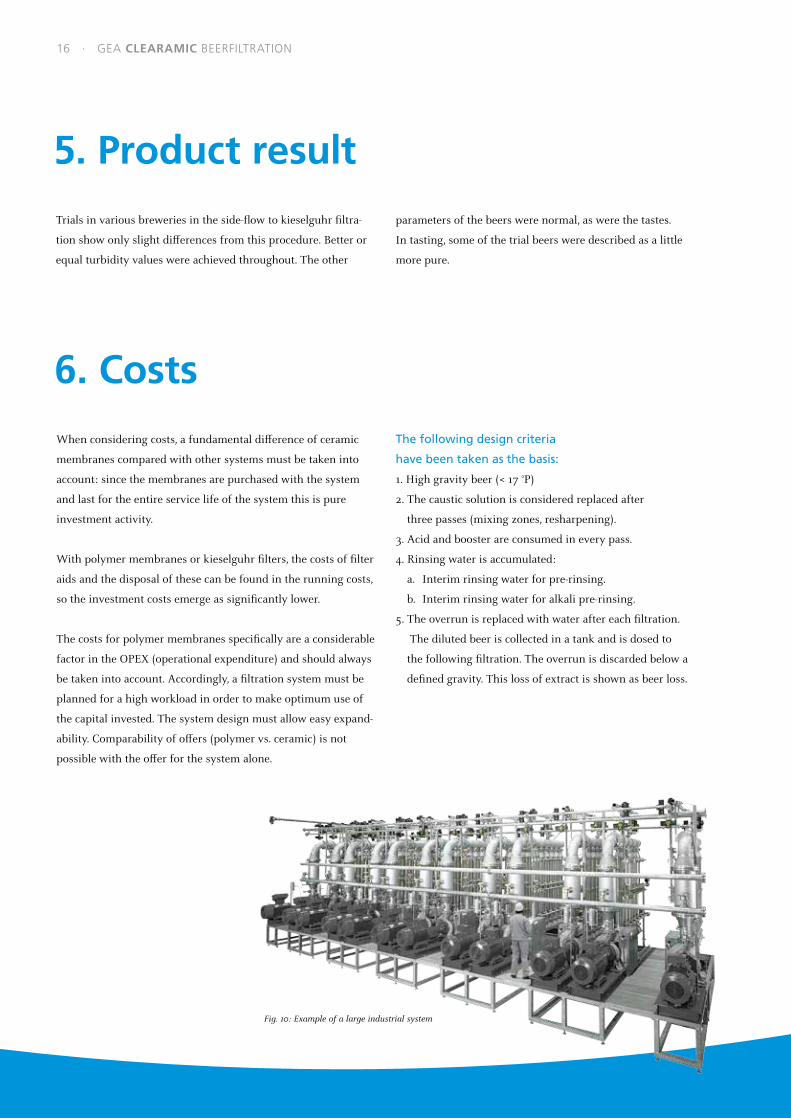
Fig. 10: Example of a large industrial system
16 · GEA CLEARAMIC BEERFILTRATION

0.0 2.0 4.0 6.0 8.0 10.0 12.0
OPEX total
Beer losses
Air
CO2
Electricity
Steam
Glycol
Water
Booster
Caustic
Acid
Costs (€c/hl)
Fig. 11: clearamic BeerFiltration – example for filtration costs
7. Summary
GEA clearamic BeerFiltration is the first waste-free beer filtra-
tion process. Filter aids can be completely omitted. Sustainable
and at the same time cost-cutting process management is thus
supported at the critical point. In parallel with this, the process
fulfils the consumer desire for crystal clear beer in permanently
consistent quality. As the studies have shown, the beer quality
remains consistently high with clearamic BeerFiltration.
With the use of ceramic membranes, beer filtration is carried
out with greater process reliability, since in the case of proper
integration, there is no risk of membrane breakage. Ceramic is
food-neutral, so there is no risk of contamination. The service
life of the ceramic membranes is at least 10 years. The staff costs
are low. No expensive special cleaning agents are needed. In
conclusion, the process is therefore economically superior to
alternative products.
GEA CLEARAMIC BEERFILTRATION · 17

GEA: proven partner to the brewing industry
Beer is one of the most multifaceted consumables
created by human society. Unlike wine, of which the
taste is dependent not least on the climatic condi-
tions of the respective vintage, the consumer expects
the preferred brand of beer to always taste exactly
the same. Constant quality down to the finest
flavor nuances is therefore the central aim of such
production.
To permanently guarantee this stability, breweries all
over the world have been working with equipment
and technologies from GEA for generations.
GEA is one of the largest suppliers of process
technology and components for the food, beverage
and energy industries. As an international technology
group, the company focuses on sophisticated
production processes.
Breweries have been working with equipment from GEA and production plants designed, erected and commissioned by GEA for over 100 years. Worldwide, every second liter of beer flows through GEA components. With waste-free beer filtration, new options are now opening up in the sustainable orientation of process management.
Based on its decades of experience, the company
has acquired great brewery expertise, which is
equally valued by regional craft breweries and by
large industrial businesses of world-famous brands.
The mature process technology of the company,
innovations in equipment technology and customized
solutions contribute significantly to an economic
process and to consistently high product quality.
GEA clearamic BeerFiltration seamlessly
continues the innovation series:
waste-free filtration with ceramic membranes has
already proven its advantages in the production of
fruit juice and in beer recovery. With this process,
breweries can now place their beer filtration
on a more sustainable basis, which also satisfies
demanding beer connoisseurs: No Waste. Pure Taste.
18 · GEA CLEARAMIC BEERFILTRATION

GEA CLEARAMIC BEERFILTRATION · 19

GEA Group is a global engineering company with multi-billion euro sales and operations in more than
50 countries. Founded in 1881, the company is one of the largest providers of innovative equipment and
process technology. GEA Group is listed in the STOXX® Europe 600 Index.
We live our values.Excellence • Passion • Integrity • Responsibility • GEA-versity
Werner-Habig-Straße 1
59302 Oelde, Germany
Tel +49 2522 77-0
Fax +49 2522 77-2089
gea.com
GEA Germany
GEA Westfalia Separator Group GmbH
The
info
rmat
ion
cont
aine
d in
thi
s br
ochu
re m
erel
y se
rves
as
a no
n-bi
ndin
g de
scrip
tion
of o
ur p
rodu
cts
and
is w
ithou
t gu
aran
tee.
Bin
ding
info
rmat
ion,
in p
artic
ular
rel
atin
g to
cap
acity
dat
a an
d su
itabi
lity
for
spec
ific
appl
icat
ions
, can
onl
y be
pro
vide
d w
ithin
the
fra
mew
ork
of c
oncr
ete
inqu
iries
. Pr
inte
d on
chl
orin
e-fr
ee b
leac
hed
pape
r · P
rinte
d in
Ger
man
y · S
ubje
ct t
o m
odifi
catio
n · W
estf
alia
® a
nd W
estf
alia
Sep
arat
or ® a
re r
egis
tere
d tr
adem
arks
of
GEA
Mec
hani
cal E
quip
men
t G
mbH
. · B
_BE-
17-0
4-00
30 E
N