washington state bridge inspection manual · , hydraulic engineering circular (hec) no. 18 •...
TRANSCRIPT

Bridge Preservation Office/Highway and Local Programs
Washington State Bridge Inspection ManualM 36-64.03
November 2012

Americans with Disabilities Act (ADA) InformationMaterials can be made available in an alternate format by emailing the WSDOT Diversity/ADA Compliance Team at [email protected] or by calling toll free, 855-362-4ADA (4232). Persons who are deaf or hard of hearing may make a request by calling the Washington State Relay at 711.
Title VI Notice to the PublicIt is Washington State Department of Transportation (WSDOT) policy to ensure no person shall, on the grounds of race, color, national origin, or sex, as provided by Title VI of the Civil Rights Act of 1964, be excluded from participation in, be denied the benefits of, or be otherwise discriminated against under any of its federally funded programs and activities. Any person who believes his/her Title VI protection has been violated may file a complaint with WSDOT’s Office of Equal Opportunity (OEO). For Title VI complaint forms and advice, please contact OEO’s Title VI Coordinator at 360-705-7082 or 509-324-6018.
To get the latest information on WSDOT publications, sign up for individual email updates at www.wsdot.wa.gov/publications/manuals.
Washington State Department of Transportation Bridge Preservation Office PO Box 47340 Olympia, WA 98504-7340 www.wsdot.wa.gov/eesc/bridge/
Washington State Bridge Inspection Manual M 36-64.03 Page iii November 2012
Foreword
The Washington State Bridge Inspection Manual (WSBIM) is published jointly by the Bridge and Structures and the Highways and Local Programs offices of the Washington State Department of Transportation (WSDOT). This manual is the primary source of information and guidance for those who inspect bridges subject to the National Bridge Inspection Standards (NBIS) managed by state and local agencies in Washington State.
This publication is the official source for all information relevant to Washington State’s compliance with the NBIS, the National Bridge Inventory, and the Washington State Bridge Inventory. It is also the official source of information for the inspection of bridges and selected structures on state right of way that are not subject to the NBIS, and for the recordkeeping requirements for these bridges and selected structures in the Washington State Bridge Inventory.
The WSBIM is managed by the Bridge Inspection Committee composed of individuals listed in this document. Suggestions for improvement and updating the manual are always welcome. All questions and comments regarding this manual will be reviewed by this committee and incorporated into subsequent revisions as appropriate.
Approved: Approved:
________________________________ _________________________________ Harvey Coffman, P.E, S.E. Debbie Lehmann, P.E. WSDOT Bridge Preservation Engineer/ FHWA Washington Division Bridge Engineer Washington State Bridge Program Manager

Foreword
Page iv Washington State Bridge Inspection Manual M 36-64.03 November 2012
Bridge Inspection Committee Members
Jody Bywater, P.E.Quality Assurance EngineerWSDOT Bridge PreservationPO Box 47341Olympia, WA [email protected]
Dave Mounts, Co-ChairHighways and Local Programs SupervisorWSDOT Highways and Local ProgramsPO Box 47390Olympia, WA [email protected]
Grant Griffin, P.E.Highways and Local Programs Bridge EngineerWSDOT Highways and Local ProgramsPO Box 47390Olympia, WA [email protected]
Glen Scroggins, Co-Chair, P.E., S.E.Bridge Preservation SupervisorWSDOT Bridge PreservationPO Box 47341Olympia, WA [email protected]
Debbie Lehmann, P.E.WA Division Bridge EngineerFHWA 711 South Capitol WayOlympia, WA [email protected]
Bruce Thill, P.E.Bridge Asset ManagerWSDOT Bridge and StructuresPO Box 47340Olympia, WA [email protected]
WSBIM Contributors
Mohamad Al-Salman, P.E.Heath BrightDave Bruce, P.E.George Comstock, P.E.Barbara JohnstoneRoman Peralta, P.E.Larry VedenCraig Yasuda, P.E.

Washington State Bridge Inspection Manual M 36-64.03 Page v November 2012
Comment Request Form
Date:
From:
Phone:
Email:
To: Bridge Preservation Engineer Washington State Department of Transportation PO Box 47340 Olympia, WA 98504-7340
Subject: Bridge Inspection Manual Comment
Recommendation for Improvement:

Comment Request Form
Page vi Washington State Bridge Inspection Manual M 36-64.03 November 2012

Washington State Bridge Inspection Manual M 36-64.03 Page vii November 2012
Contents
PageForeword . . . . . . . . . . . . . . . . . . . . . . . . . . . . . . . . . . . . . . . . . . . . . . . . . . . . . . . . . . . . . . . . . . . . . . . . . . . . . . iii
Bridge Inspection Committee Members . . . . . . . . . . . . . . . . . . . . . . . . . . . . . . . . . . . . . . iv
Comment Request Form . . . . . . . . . . . . . . . . . . . . . . . . . . . . . . . . . . . . . . . . . . . . . . . . . . . . . . . . . . . . . . . . . v
Introduction . . . . . . . . . . . . . . . . . . . . . . . . . . . . . . . . . . . . . . . . . . . . . . . . . . . . . . . . . . . . . . . . . . . . . . . . . . . xiPurpose . . . . . . . . . . . . . . . . . . . . . . . . . . . . . . . . . . . . . . . . . . . . . . . . . . . . . . . . . . . . . . . . xiReferences . . . . . . . . . . . . . . . . . . . . . . . . . . . . . . . . . . . . . . . . . . . . . . . . . . . . . . . . . . . . . xiRevisions . . . . . . . . . . . . . . . . . . . . . . . . . . . . . . . . . . . . . . . . . . . . . . . . . . . . . . . . . . . . . .xii
Chapter 1 Bridge Inspection Organization Requirements . . . . . . . . . . . . . . . . . . . . . . . . . . . . . . . 1-11 .01 General . . . . . . . . . . . . . . . . . . . . . . . . . . . . . . . . . . . . . . . . . . . . . . . . . . . . . . . . . . 1-11 .02 Description of Bridge Inspection Organization . . . . . . . . . . . . . . . . . . . . . . . . . . . 1-4
Chapter 2 Bridge Files (Records) . . . . . . . . . . . . . . . . . . . . . . . . . . . . . . . . . . . . . . . . . . . . . . . . . . . . . 2-12 .01 General . . . . . . . . . . . . . . . . . . . . . . . . . . . . . . . . . . . . . . . . . . . . . . . . . . . . . . . . . . 2-12 .02 Maintaining Bridge Files (Records) . . . . . . . . . . . . . . . . . . . . . . . . . . . . . . . . . . . . 2-22 .03 Maintaining a State Bridge Inventory – WSBIS . . . . . . . . . . . . . . . . . . . . . . . . . . 2-42 .04 FHWA Data Submittal Process . . . . . . . . . . . . . . . . . . . . . . . . . . . . . . . . . . . . . . 2-102 .05 Responding to FHWA . . . . . . . . . . . . . . . . . . . . . . . . . . . . . . . . . . . . . . . . . . . . . 2-112 .06 Appendices . . . . . . . . . . . . . . . . . . . . . . . . . . . . . . . . . . . . . . . . . . . . . . . . . . . . . . 2-12
Appendix 2 .06-A Components of a Bridge Record . . . . . . . . . . . . . . . . . 2 .06-A-1Appendix 2 .06-B Record Change Form . . . . . . . . . . . . . . . . . . . . . . . . . . 2 .06-B-1Appendix 2 .06-C Washington State Bridge Inventory System Coding Guide . . . . . . . . . . . . . . . . . . . . . . . . . . . . . . . . 2 .06-C-1Appendix 2 .06-D Local Agency Bridge Inventory Coding Guide . . . . . . 2 .06-D-1Appendix 2 .06-E Memorandum . . . . . . . . . . . . . . . . . . . . . . . . . . . . . . . . 2 .06-E-1
Chapter 3 Inspections and Reports . . . . . . . . . . . . . . . . . . . . . . . . . . . . . . . . . . . . . . . . . . . . . . . . . . . 3-13 .01 General . . . . . . . . . . . . . . . . . . . . . . . . . . . . . . . . . . . . . . . . . . . . . . . . . . . . . . . . . . 3-13 .02 Inspection Types and Reporting . . . . . . . . . . . . . . . . . . . . . . . . . . . . . . . . . . . . . . . 3-13 .03 Bridge Inspection Orientation . . . . . . . . . . . . . . . . . . . . . . . . . . . . . . . . . . . . . . . 3-293 .04 Policy and Procedures . . . . . . . . . . . . . . . . . . . . . . . . . . . . . . . . . . . . . . . . . . . . . 3-333 .05 Forms . . . . . . . . . . . . . . . . . . . . . . . . . . . . . . . . . . . . . . . . . . . . . . . . . . . . . . . . . . 3-423 .06 Appendices . . . . . . . . . . . . . . . . . . . . . . . . . . . . . . . . . . . . . . . . . . . . . . . . . . . . . . 3-72
Appendix 3 .06-A1 Bridge With Fill on Deck . . . . . . . . . . . . . . . . . . . . . . 3 .06-A1-1Appendix 3 .06-A2 Bridge With No Fill on Deck . . . . . . . . . . . . . . . . . . . 3 .06-A2-1Appendix 3 .06-A3 Culvert With Fill on Deck . . . . . . . . . . . . . . . . . . . . . 3 .06-A3-1Appendix 3 .06-B UBIT Inspections and Procedures . . . . . . . . . . . . . . . . 3 .06-B-1Appendix 3 .06-C FHWA Letter for Routine Extended Frequency Inspections . . . . . . . . . . . . . . . . . . . . . . . . . 3 .06-C-1Appendix 3 .06-D FHWA Letter for Bridge Special Feature Inspections . 3 .06-D-1

Contents
Page viii Washington State Bridge Inspection Manual M 36-64.03 November 2012
PageChapter 4 WSDOT Bridge Elements . . . . . . . . . . . . . . . . . . . . . . . . . . . . . . . . . . . . . . . . . . . . . . . . . . . 4-1
4 .0 Introduction . . . . . . . . . . . . . . . . . . . . . . . . . . . . . . . . . . . . . . . . . . . . . . . . . . . . . . 4-14 .1 Bridge Decks . . . . . . . . . . . . . . . . . . . . . . . . . . . . . . . . . . . . . . . . . . . . . . . . . . . . . 4-64 .2 Superstructure . . . . . . . . . . . . . . . . . . . . . . . . . . . . . . . . . . . . . . . . . . . . . . . . . . . 4-124 .3 Substructure . . . . . . . . . . . . . . . . . . . . . . . . . . . . . . . . . . . . . . . . . . . . . . . . . . . . . 4-324 .4 Culverts . . . . . . . . . . . . . . . . . . . . . . . . . . . . . . . . . . . . . . . . . . . . . . . . . . . . . . . . 4-474 .5 Tunnels . . . . . . . . . . . . . . . . . . . . . . . . . . . . . . . . . . . . . . . . . . . . . . . . . . . . . . . . . 4-484 .6 Sidewalk and Supports . . . . . . . . . . . . . . . . . . . . . . . . . . . . . . . . . . . . . . . . . . . . . 4-494 .7 Bearings . . . . . . . . . . . . . . . . . . . . . . . . . . . . . . . . . . . . . . . . . . . . . . . . . . . . . . . . 4-514 .8 Bridge Rail . . . . . . . . . . . . . . . . . . . . . . . . . . . . . . . . . . . . . . . . . . . . . . . . . . . . . . 4-544 .9 Pedestrian Rail . . . . . . . . . . . . . . . . . . . . . . . . . . . . . . . . . . . . . . . . . . . . . . . . . . . 4-554 .10 Smart Flags . . . . . . . . . . . . . . . . . . . . . . . . . . . . . . . . . . . . . . . . . . . . . . . . . . . . . 4-564 .11 Seismic Restrainers . . . . . . . . . . . . . . . . . . . . . . . . . . . . . . . . . . . . . . . . . . . . . . . 4-594 .12 Expansion Joint BMS . . . . . . . . . . . . . . . . . . . . . . . . . . . . . . . . . . . . . . . . . . . . . 4-624 .13 Movable Bridges . . . . . . . . . . . . . . . . . . . . . . . . . . . . . . . . . . . . . . . . . . . . . . . . . 4-714 .14 Other Bridge Elements . . . . . . . . . . . . . . . . . . . . . . . . . . . . . . . . . . . . . . . . . . . . . 4-724 .15 Bridge Deck Overlays . . . . . . . . . . . . . . . . . . . . . . . . . . . . . . . . . . . . . . . . . . . . . 4-744 .16 Protective Coatings . . . . . . . . . . . . . . . . . . . . . . . . . . . . . . . . . . . . . . . . . . . . . . . 4-74
Chapter 5 Bridge Analysis . . . . . . . . . . . . . . . . . . . . . . . . . . . . . . . . . . . . . . . . . . . . . . . . . . . . . . . . . . . . 5-15 .01 General . . . . . . . . . . . . . . . . . . . . . . . . . . . . . . . . . . . . . . . . . . . . . . . . . . . . . . . . . . 5-15 .02 Bridge Load Rating . . . . . . . . . . . . . . . . . . . . . . . . . . . . . . . . . . . . . . . . . . . . . . . . 5-15 .03 Scour Evaluation . . . . . . . . . . . . . . . . . . . . . . . . . . . . . . . . . . . . . . . . . . . . . . . . . . 5-55 .04 Appendices . . . . . . . . . . . . . . . . . . . . . . . . . . . . . . . . . . . . . . . . . . . . . . . . . . . . . . 5-10
Appendix 5 .04-A WSDOT Plan of Action Template . . . . . . . . . . . . . . . . 5 .04-A-1Appendix 5 .04-B FHWA Plan of Action Template . . . . . . . . . . . . . . . . . . 5 .04-B-1Appendix 5 .04-C Instructions for Completing the Plan of Action . . . . . . 5 .04-C-1
Chapter 6 Damage and Repairs . . . . . . . . . . . . . . . . . . . . . . . . . . . . . . . . . . . . . . . . . . . . . . . . . . . . . . . 6-16 .01 General . . . . . . . . . . . . . . . . . . . . . . . . . . . . . . . . . . . . . . . . . . . . . . . . . . . . . . . . . . 6-16 .02 Bridge Damage Report . . . . . . . . . . . . . . . . . . . . . . . . . . . . . . . . . . . . . . . . . . . . . 6-16 .03 Bridge Repairs . . . . . . . . . . . . . . . . . . . . . . . . . . . . . . . . . . . . . . . . . . . . . . . . . . . 6-66 .04 Maintenance - Bridge Repair Report . . . . . . . . . . . . . . . . . . . . . . . . . . . . . . . . . 6-146 .05 Forms . . . . . . . . . . . . . . . . . . . . . . . . . . . . . . . . . . . . . . . . . . . . . . . . . . . . . . . . . . 6-14

Contents
Washington State Bridge Inspection Manual M 36-64.03 Page ix November 2012
PageChapter 7 Quality Control/Quality Assurance . . . . . . . . . . . . . . . . . . . . . . . . . . . . . . . . . . . . . . . . . . 7-1
7 .01 General . . . . . . . . . . . . . . . . . . . . . . . . . . . . . . . . . . . . . . . . . . . . . . . . . . . . . . . . . . 7-17.02 WSDOTBridgePreservationOfficeQualityControlProgram . . . . . . . . . . . . . . . 7-27 .03 Coding and Appraisal Unit . . . . . . . . . . . . . . . . . . . . . . . . . . . . . . . . . . . . . . . . . . . 7-37 .04 Risk Reduction Unit (Load Rating) . . . . . . . . . . . . . . . . . . . . . . . . . . . . . . . . . . . . 7-67 .05 Risk Reduction Unit (Scour Group) . . . . . . . . . . . . . . . . . . . . . . . . . . . . . . . . . . . 7-77 .06 Regionald and Special Structures Inspection Units . . . . . . . . . . . . . . . . . . . . . . . . 7-87 .07 Underwater Inspection Unit . . . . . . . . . . . . . . . . . . . . . . . . . . . . . . . . . . . . . . . . . 7-107.08 WSDOTBridgePreservationOfficeQualityAssurnaceProgram . . . . . . . . . . . 7-117.09 WSDOTH&LPQualityControl/QualityAssuranceProgram . . . . . . . . . . . . . . 7-137.10 WSDOTH&LPQualityControlProgram . . . . . . . . . . . . . . . . . . . . . . . . . . . . . . 7-137.11 WSDOTH&LPQualityAssuranceProgram . . . . . . . . . . . . . . . . . . . . . . . . . . . . 7-187 .12 Appendices . . . . . . . . . . . . . . . . . . . . . . . . . . . . . . . . . . . . . . . . . . . . . . . . . . . . . . 7-21
Appendix 7 .12-A Bridge Letter File Contents for State Bridges . . . . . . . 7 .12-A-1Appendix 7 .12-B Flowchart for Tracking New Bridges . . . . . . . . . . . . . 7 .12-B-1Appendix7.12-C BridgePreservationOfficeFloorPlan . . . . . . . . . . . . . 7 .12-C-1Appendix 7 .12-D WSBIS Fields Maintained With Other WSDOT Database Source Information . . . . . . . . . . . . 7 .12-D-1Appendix7.12-E BridgePreservationOfficeLeadApprovalCriteria . . . 7 .12-E-1Appendix7.12-F BridgePreservationOfficeQualityControlReview Tracking Form . . . . . . . . . . . . . . . . . . . . . . . . . . . . . . . .7 .12-F-1Appendix7.12-G BridgePreservationOfficeQualityControlReport Review Tracking Form . . . . . . . . . . . . . . . . . . . . . . . . 7 .12-G-1Appendix7.12-H BridgePreservationOfficeQualityControlField Review Form . . . . . . . . . . . . . . . . . . . . . . . . . . . . . . . . 7 .12-H-1Appendix7.12-I BridgePreservationOfficeRecertificationProgram . . . 7 .12-I-1Appendix7.12-J BridgePreservationOfficeQualityAssurance Bridge Selection Process . . . . . . . . . . . . . . . . . . . . . . . . 7 .12-J-1Appendix7.12-K BridgePreservationOfficeFieldReview . . . . . . . . . . 7 .12-K-1Appendix7.12-L BridgePreservationOfficeDecertification/ Reinstatement . . . . . . . . . . . . . . . . . . . . . . . . . . . . . . . . 7 .12-L-1Appendix7.12-M H&LPContinuedCertificationofBridge Inspection Personnel . . . . . . . . . . . . . . . . . . . . . . . . . . 7 .12-M-1Appendix7.12-N H&LPCertificationSuspensionandReinstatement . . 7 .12-N-1Appendix7.12-O H&LPQualityAssuranceDeficiencies . . . . . . . . . . . . 7 .12-O-1

Contents
Page x Washington State Bridge Inspection Manual M 36-64.03 November 2012

Washington State Bridge Inspection Manual M 36-64.03 Page xi November 2012
Introduction
PurposeThe Washington State Bridge Inspection Manual (WSBIM) has been developed to provide specific guidance, offer needed technical details, and serve as an information source to both state and local agency staff related to and involved with bridge inspections within the state of Washington. The intent of this manual is to serve as an operations manual for the collection and reporting of bridge inspection information.
The WSBIM is currently divided up into seven chapters. The first three chapters explain the responsibilities within the bridge inspection organization, provide guidance to the structure of the Washington State Bridge Inventory System (WSBIS), and further explains the types of inspections and the reports required to meet the federal mandate outlined in the Code of Federal Regulations. The fourth chapter describes the Washington State Bridge Management System (BMS) and defines the element level inspection used by both state and local agency bridge inspectors. The final three chapters provide more detailed information to the inspector in regard to load ratings, scour, damage/repair reporting, and quality control/quality assurance.
ReferencesBridge inspection staff may also refer to the most current editions of the following:
• Bridge Inspector’s Reference Manual (BIRM), Publication No. FHWA NHI 12-049
• The Manual for Bridge Evaluation, 2nd Edition, AASHTO
• Evaluating Scour at Bridges, Hydraulic Engineering Circular (HEC) No. 18
• Title 23 CFR 650 Subchapter C – National Bridge Inspection Standards
• Title 23 CFR 500 Subchapter F – Transportation Infrastructure Officials
• Recording and Coding Guide for the Structure Inventory and Appraisal of the Nation’s Bridges, Report No. FHWA-PD-96-001, December 1995, FHWA available at www.fhwa.dot.gov/bridge/mtguide.pdf.
• Detail Manual for Certification in the Field of Transportation Engineering Technology – Subfield of Bridge Safety Inspection, contains the requirements for NICET certification. Contact the National Institute for Certification in Engineering Technologies
• Transportation Structures Preservation Manual M 23-11
• Local Agency Guidelines (LAG) M 36-63, WSDOT
• Washington State Bridge List M 23-09

Introduction
Page xii Washington State Bridge Inspection Manual M 36-64.03 November 2012
RevisionsThe WSBIM is a dynamic document that is updated periodically to incorporate revisions based on new requirements from FHWA, as well as newly adopted practices by either state or local agencies within the state. We encourage the user to submit to the Bridge Inspection Committee any proposed revisions or new material, by using the Comment Request Form provided.
In the event of conflicting information or requirements between the WSBIM and NBIS, the NBIS will govern. Agencies are not relieved of the responsibility of complying with the NBIS even when a conflict exists. If a conflict is discovered, notify the WSDOT Regional Bridge Inspection Engineer or the Local Agency Bridge Engineer at once.

Washington State Bridge Inspection Manual M 36-64.03 Page 1-1 November 2012
Chapter 1 Bridge Inspection Organization Requirements
1.01 GeneralThe National Bridge Inspection Standards (NBIS) are published in the Code of Federal Regulations, 23 CFR 650, Subpart C. The NBIS sets the national standard for the proper safety inspection and evaluation of bridges and apply to all structures defined as highway bridges located on all public roads. Washington State’s bridge inspection organization is required to meet the NBIS and functions under the authority of the Federal Highway Administration (FHWA) and state law.
In Washington State, the bridge inspection organization is structured as a collaborative effort by the Washington State Department of Transportation (WSDOT) Bridge Preservation Office, WSDOT Highways and Local Programs Office, most county roadway agencies, and many city roadway agencies. Collectively, all state and local agency owned bridges subject to the NBIS are managed under this organization.
With respect to the organization’s activities, the NBIS requires the following:
• Performing regularly scheduled in-service bridge inspections.
• Maintaining bridge records.
• Maintaining a state bridge inventory.
• Submitting selected state bridge inventory data to FHWA for incorporation into the National Bridge Inventory (NBI) (timely reporting of significantly damaged bridges to the FHWA Washington Division).
• Maintaining current load ratings on all NBI structures.
• Maintaining current scour plans of action for all bridges considered vulnerable to scour.
• A quality control and quality assurance program.
There are a few activities that are not explicitly required by the NBIS, but are either strongly implied or required by other FHWA policies:
• Performing scour evaluations for all bridges over water.
• Maintaining personnel qualification records and an inspector certification program.
• Responding to FHWA Technical Advisories, FHWA Action Memoranda, and other policy or information requirements provided by the FHWA Washington Division Bridge Engineer.
There are a few more activities addressed in this manual which are clearly part of managing bridges but not required by the NBIS. These include:
• Bridge Management System data, recommended but not required by Title 23 Code of Federal Regulations 500 Subchapter F.

Bridge Inspection Organization Requirements Chapter 1
Page 1-2 Washington State Bridge Inspection Manual M 36-64.03 November 2012
• Bridge repair management.
• Managing non-NBIS structures.
The NBIS applies to all publicly-owned highway bridges longer than 20 feet located on public roads. The WSDOT bridge inspection organization, however, is only responsible for state and local agency-owned bridges. Federally-owned bridges are inventoried and managed by a variety of federal agencies. Privately-owned highway bridges of any length are not included in this requirement, although WSDOT encourages private bridge owners to inventory, inspect, and maintain their bridges in conformance with the NBIS and this manual.
A. Definitions
Some definitions for use with this manual are as follows:
Bridge – The NBIS gives the following definition: “A structure including supports erected over a depression or an obstruction, such as water, highway, or railway, and having a track or passageway for carrying traffic or other moving loads, and having an opening measured along the center of the roadway of more than 20 feet between undercopings of abutments or spring lines of arches, or extreme ends of openings for multiple boxes. It may also include multiple pipes, where the clear distance between openings is less than half of the smaller contiguous opening.”
Bridge Inspection Organization – A state department of transportation that is required by the NBIS to inspect, or cause to be inspected, all highway bridges located on public roads that are fully or partially within the state’s boundaries, except for bridges that are owned by federal agencies. The bridge inspection organization is managed under the guidance of a Statewide Program Manager, with the intent and responsibility to meet the requirements of the NBIS.
Bridge Inspection Program – An organizational unit that functions as part of the Bridge Inspection Organization and that meets the requirements of 23 CFR 650.307 and this manual. Agencies that meet this requirement are led by delegated program managers, and all agencies work in coordination with the Statewide Program Manager.
Bridge Condition Inspection Training (BCIT) – A comprehensive bridge inspector training course offered by WSDOT which FHWA accepts as equivalent to the Safety Inspection of In-Service Bridges FHWA-NHI-130055 course.
Bridge File – A file containing historic and current information about a bridge, and meeting the intent of Chapter 2 of the AASHTO Manual for Bridge Evaluation.
Bridge Inspection – The condition inspection and evaluation of in-service bridges.
Bridge Reporting Database – The database which stores the Washington State Bridge Inventory System (WSBIS) data, combining data from the BPO and HLP databases.
BridgeWorks – The software application that is used to perform bridge inspections and which updates data in the various inventory databases.
Chapter 1 Bridge Inspection Organization Requirements
Washington State Bridge Inspection Manual M 36-64.03 Page 1-3 November 2012
Critical Finding – Also known as critical damage in the state of Washington.
Fracture Critical Member – A member in tension, or with a tension element, whose failure would probably cause a portion of or the entire bridge to collapse.
H&LP Bridge Inventory – The inventory of local agency bridges kept in the H&LP database. The Bridge Reporting Database draws data from this database regularly for inclusion into WSBIS.
Inventory Route – The route for which the applicable inventory data is to be recorded. The inventory route may be on the structure or under the structure. Generally inventories along a route are made from west to east and south to north.
Inventory Record – Data which has been coded according to this manual for each structure carrying public road traffic or each inventory route which goes under a structure.
Local Agency – Generally refers to city or county bridge owners but also includes bridge owners other than state and federal.
National Bridge Inspection Standards (NBIS) – Title 23 Code of Federal Regulations 650 Part C defines the NBIS regulations, and establishes requirements for inspection procedures, frequency of inspections, qualifications of personnel, inspection reports, and preparation and maintenance of a state bridge inventory. The NBIS apply to all structures defined as bridges located on all public roads.
Public Road – Any road under the jurisdiction of and maintained by a public authority and open to public travel.
National Bridge Inventory (NBI) – The aggregation of structure inventory and appraisal data collected to fulfill the requirements of the National Bridge Inspection Standards. Each state shall prepare and maintain an inventory of all bridges subject to the NBIS.
Washington State Bridge Inventory System (WSBIS) – The aggregation of structure inventory and appraisal data collected and used to fulfill the requirements of the NBIS and additional data used to manage the state and local bridge inventories. This data is stored in the Bridge Reporting Database.
The State –The Washington State Department of Transportation (WSDOT).
State System Bridge Inventory – The inventory of state bridges kept in the BPO database. The Bridge Reporting Database draws data from this database regularly for inclusion into WSBIS.
Statewide Program Manager – The individual in Washington State with overall responsibility to ensure that all the bridge inspection programs meet the requirements of the NBIS.
Delegated Program Manager – Individuals with functional responsibility to ensure that bridges managed by their bridge inspection program meet the requirements of the NBIS.
Bridge Inspection Organization Requirements Chapter 1
Page 1-4 Washington State Bridge Inspection Manual M 36-64.03 November 2012
Bridge Inspection Committee – A committee of state and/or local agency representatives that provides overall advisory input to the bridge inspection organization within the state of Washington. The list of members is in the Foreword of this manual.
1.02 Description of Bridge Inspection OrganizationWashington State’s bridge inspection organization is required by the NBIS, led by the State Bridge Preservation Engineer (who serves as the Statewide Program Manager) and advised by the Bridge Inspection Committee. The bridge inspection organization has the following responsibilities:
• Establishing policies and procedures.
• Maintaining the state bridge inventory and regularly reporting NBI data to the FHWA.
• Maintaining personnel qualification records and an inspector certification program.
• Maintaining a quality control and quality assurance program.
All the other activities required by the NBIS are the responsibility of the various bridge inspection programs operating within state and local agency governments. The composition and size of each inspection program varies widely, generally depending on the number of bridges managed by the agency. Two state offices play key roles in the organization:
• Bridge Preservation Office (BPO) – This office is dedicated to running the bridge inspection program for all state owned bridges. This includes bridges managed by State Parks, General Administration, and other state agencies with bridges subject to the NBIS. BPO also manages bridges on the border with Oregon and Idaho. BPO is led by the Bridge Preservation Engineer.
• Highways and Local Programs (H&LP) – This office provides support and services to local agency bridge inspection programs. In particular, H&LP provides training, manages the inspector certification program, and manages many aspects of the local agency bridge inventory data. The WSDOT Local Agency Bridge Engineer functions as a delegated program manager for all local agency bridges.
As mentioned above, local agencies have a wide variety of bridge inspection programs, which generally fall into the following categories:
• Local agencies with a delegated program manager and bridge inspection staff working directly for him/her.
• Local agencies without a delegated program manager but with bridge inspection staff.
• Local agencies without a bridge inspection program. These agencies, usually smaller and mid-sized cities, generally have agreements with other agencies, usually the surrounding county, to inspect and manage their bridges.

Chapter 1 Bridge Inspection Organization Requirements
Washington State Bridge Inspection Manual M 36-64.03 Page 1-5 November 2012
The bridge inspection organization, and the various programs within it, are staffed by individuals who have defined roles and responsibilities described as follows.
A. Statewide Program Manager (SPM)
The Statewide Program Manager is the individual in Washington State who leads the bridge inspection organization. This position is held by the Bridge Preservation Engineer, who must ensure that the organization fulfills its NBIS responsibilities. To qualify as the Statewide Program Manager, WSDOT requires this individual to have both a current Structural Engineering and Professional Engineering license and qualify as a certified team leader. The Statewide Program Manager must also be recertified on a regular basis by attending a refresher training class accepted by FHWA. The certification process is described in detail in Chapter 7.
B. Delegated Program Manager (DPM)
A delegated program manager assumes some functions for the program manager for the selected subset of bridges under his or her direct control. To qualify as a delegated program manager, the individual must meet, at a minimum, the program manager requirements as described in the NBIS. Delegated program managers must be recertified on a regular basis by attending a refresher training class accepted by FHWA. The certification process is described in detail in Chapter 7.
Note that though delegated program managers perform functions for the bridge inspection organization, overall responsibility for NBIS compliance still resides with the Statewide Program Manager.
C. Team Leader (TL)
A team leader is in charge of an inspection team and responsible for planning, preparing, and performing the field inspection of bridges. The team leader also makes repair recommendations and is responsible for initiating the critical damage procedures including full bridge closure if deemed necessary. To qualify as a team leader, the individual must meet, at a minimum, the team leader requirements as described in the NBIS. Team leaders must be recertified on a regular basis by attending a refresher training class accepted by FHWA. The certification process is described in detail in Chapter 7.
D. Assistant Inspector
An assistant inspector may accompany the team leader during field bridge inspections. Typical duties include helping to organize bridge inspection trips, taking measurements, compiling notes, and taking photographs. When assistant inspectors also fully participate in the inspection process and prepare inspection reports under the direct supervision of a team leader, this work provides qualifying experience towards certification as a team leader.
The NBIS does not set specific training or educational requirements for assistant inspectors. However, bridge inspector training is recommended and available to all assistant bridge inspectors to serve as a good foundation for beginning inspectors as well as being a requirement for advancement to team leader.

Bridge Inspection Organization Requirements Chapter 1
Page 1-6 Washington State Bridge Inspection Manual M 36-64.03 November 2012
E. Load Rating Engineer (LRE)
A load rating engineer manages all aspects of maintaining current and accurate load ratings for bridges he/she is responsible for. Responsibilities include reviewing inspection reports for changed conditions that warrant revisions to the load ratings on file, revising load ratings as needed, creating new load ratings for new bridges, and ensuring that the findings from load ratings are implemented. In particular, the load rating engineer must track bridges that require posting and ensure that the bridge inventory has current data from the load ratings.
To qualify as a load rating engineer, the individual must have a current Professional Engineering license and completed the Fundamentals of LRFR FHWA-NHI-130092 and LRFR for Highway Bridges FHWA-NHI-130092A classes.
F. Underwater Bridge Inspection Diver (UBID)
To qualify as an underwater bridge inspection diver, the individual must meet, at a minimum, the underwater bridge inspection diver requirements as described in the NBIS. The certification process is described in detail in Chapter 7.

Washington State Bridge Inspection Manual M 36-64.03 Page 2-1 November 2012
Chapter 2 Bridge Files (Records)
2.01 GeneralThis chapter establishes policies on how the Washington State Department of Transportation (WSDOT) and local agencies maintain bridge records, both to meet Federal Highway Administration (FHWA) requirements and effectively manage physical assets (also sometimes referred to as physical features) on WSDOT right of way. These policies apply to structures that are commonly called bridges, culverts, tunnels, lids, detention vaults, overpasses, and undercrossings when they meet certain criteria generally based on structure geometry, location, and use which will be described in more detail below.
These policies also apply differently depending on bridge ownership and location and fall into three main categories:
1. WSDOT-owned structures on WSDOT right of way.
2. Local agency-owned structures on WSDOT right of way.
3. Local agency-owned structures on local agency right of way.
Unless otherwise specifically noted below, all policies apply to WSDOT and local agency owned structures on WSDOT right of way. However, only those policies directly associated with FHWA requirements apply to local agency owned structures on local agency right of way. There are occasionally special circumstances in which WSDOT owns a structure on local agency right of way, and this chapter has no specific policies except that the bridge record must be maintained under all circumstances and agreements regarding bridge and bridge record maintenance shall be kept in the bridge record.
This chapter addresses the following topics associated with bridge records:
• Maintaining physical paper bridge records.
• Maintaining a state bridge inventory.
• Submitting state bridge inventory data to FHWA.
• Responding to FHWA and Program Manager requests for information.
Each topic has components that are mandated by FHWA and components that are required by WSDOT policy. The following sections clearly identify the authorizing environment.

Chapter 2 Bridge Files (Records)
Page 2-2 Washington State Bridge Inspection Manual M 36-64.03 November 2012
2.02 Maintaining Bridge Files (Records)This section is largely based on requirements established by Chapter 2 of the AASHTO Manual for Bridge Evaluation (MBE) and therefore mandated by FHWA. The MBE provides some overall guidance:
A. Bridge owners should maintain a complete, accurate, and current record of each bridge under their jurisdiction.
B. A bridge record contains the cumulative information about an individual bridge.
C. A bridge record may be stored electronically, on paper, or a mixture of both. When both electronic and paper formats are used, they should be cross-referenced in the bridge file (record).
The MBE further identifies specific types of documents to be included in the bridge record – plans, inspection reports, photos, etc. A complete listing of the components of a bridge file (record) is included in Appendix 2.06-A. Note that there are some components required by WSDOT policy that are not listed in the MBE.
For Washington State bridge records, there are some specific requirements for maintaining paper bridge records. These requirements are based on the need to provide backup data in the event that electronic data is corrupted. On this basis, BPO must maintain a file containing bridge records for all bridges under their jurisdiction and each bridge record must contain the following paper documentation:
1. All signed bridge inspection reports, including but not limited routine, fracture critical, underwater, and special report types. Signed damage inspections in response to fires, floods, earthquakes, etc shall also be included.
2. Any and all miscellaneous special inspections, studies, investigations, or record reviews. Examples include but are not limited to: load testing documentation, findings from FHWA technical advisory requests for information, survey results, or ground/slope stability studies.
3. A current printout of any specific inspection requirements, usually but not necessarily associated with fracture critical, underwater, or special inspection reports.
4. A deck and elevation photograph current enough to make the bridge clearly identifiable when compared against the actual bridge. In cases where a bridge is part of a cluster of other bridges (at a freeway interchange, for example) additional sketches or other documentation may be required to clearly locate and define the limits of the bridge.
5. Current load rating calculations. Since load ratings can be very large, it is sufficient to place a copy of the summary sheet that includes the controlling load rating factors and a signed PE stamp. However, the complete physical load rating document must be maintained on file at some location.

Bridge Files (Records) Chapter 2
Washington State Bridge Inspection Manual M 36-64.03 Page 2-3 November 2012
6. All current agreements with other agencies for maintenance, rehabilitation, or shared ownership. In cases where many bridges are covered under a single agreement, the agreement can be referenced in the bridge file components checklist.
7. A document identifying the location of any records either maintained electronically or in another file, with instructions on finding these records. In cases when the inventory boundaries between adjacent bridges is altered or re-defined, this document needs to cross-reference all related structures throughout the history of each bridge.
Note that the inspection reports, miscellaneous studies and inventory data is cumulative, meaning that all historic as well as current data must be kept in the bridge record. For all other documents listed above, only the most current record must be maintained. Appendix 2.06-A comprehensively specifies which bridge record components are maintained cumulatively.
All documents listed above may be stored electronically as a supplement to the paper files, and all other documents listed in Appendix 2.06-A may be stored either electronically or on paper. Bridge records stored electronically should have a backup system intended to protect the electronic data for the life of the structures.
2.02.01 Transferring Bridge Ownership
Whenever a bridge transfers ownership and/or program manager responsibility, the entire bridge record, both paper and electronic, must be transferred to the new owner/program manager. Bridge transfers must be acknowledged and documented by both program managers involved along with any additional deeds, agreements, plans or other documentation available. All transfer documentation must be retained in the bridge record. See Appendix 2.06-B for a checklist and program manager signoff sheet. In some cases, the acknowledgement of the transfer by the program managers may be the only documentation available.
In cases where WSDOT transfers a bridge record to another agency, a complete electronic copy of the entire bridge record is made and retained permanently. Other agencies are encouraged to follow this practice, but are not required to.
For more information about transferring electronic records in the WSBIS, see Section 2.03.03.
2.02.02 Dead Bridge Files (Records)
When a bridge is demolished or permanently removed from service and no longer considered appropriate for inclusion in the bridge inventory, the program manager for the “dead” bridge shall provide documented acknowledgement of the removal from the inventory which is retained for a minimum of five years. WSDOT maintains dead bridge files (records) permanently. Local agencies are encouraged to maintain permanent dead bridge files as well, though there is no requirement to do so.
See Section 2.03.04 for more information on processing “dead” bridge electronic records in the WSBIS.

Chapter 2 Bridge Files (Records)
Page 2-4 Washington State Bridge Inspection Manual M 36-64.03 November 2012
2.02.03 Structures on WSDOT Right of Way
WSDOT shall maintain a bridge record for all structures considered appropriate for inclusion in the WSBIS that are on the WSDOT right of way, including local agency bridges passing over state routes or adjacent to state routes, whether or not the structure is subject to the NBIS or reported to the NBI. For more information, see Section 2.03.05.
2.03 Maintaining a State Bridge Inventory – WSBISWashington State is required by 23 CFR 650.315 to maintain an inventory of all bridges (structures) subject to the National Bridge Inspection Standards (NBIS), from which selected data is reported to FHWA as requested for entry into the National Bridge Inventory (NBI). FHWA has a Stewardship Agreement with Washington State to submit NBI data on April 1 and October 1 each year. Federal law under 23 CFR Part 500 provides an option for state agencies to maintain a Bridge Management System (BMS), with the incentive that federal funding can be used with more flexibility. Washington State has chosen to implement a BMS and integrally incorporate it into the state inventory for bridges managed under the WSDOT bridge program. In addition, Washington State maintains an inventory to meet WAC 136-20-020, which requires that each county maintain an inventory of bridges in the state inventory. The Washington State Bridge Inventory System (WSBIS) is maintained to meet these federal and state laws and regulations. The WSBIS is also maintained to meet the WSDOT mission statement with respect to operating the state bridge structures, and provides a means for local agencies to do the same.
In Washington State, there are currently two separate databases which hold bridge information, one mostly holding state owned structures (BPO database) and a second mostly holding local agency owned structures (HLP database). A third database (the Bridge Reporting Database) draws data from these two databases and is the source for data reported to FHWA. This third BRD database is maintained by the WSDOT Office of Information Technology (OIT). The Washington State Bridge Inventory System (WSBIS) consists of the data held in the BRD.
The BPO database is maintained by the WSDOT Bridge Preservation Office, which maintains an associated coding guide available in Appendix 2.06-C. The HLP database is maintained by the WSDOT Highways and Local Programs Office, which also maintains an associated HLP coding guide available in Appendix 2.06-D. These coding guides are intended to define the fields maintained in the respective databases for use by bridge inspectors and inventory managers. These coding guides are largely based on the federal coding guide and must meet the following requirements:
1. Whenever a database field has to be translated to match the federal coding guide, this translation must be clearly defined.
2. The state or local agency coding guides cannot contradict the federal coding guide.
3. Required and optional fields must be clearly identified.
4. Every field must clearly state whether or not it is required for under records, and if so, exactly how it is coded for these under records.

Bridge Files (Records) Chapter 2
Washington State Bridge Inspection Manual M 36-64.03 Page 2-5 November 2012
5. When bridge records are neither “on” nor “under” (pedestrian bridge adjacent to a highway bridge for example). The coding guide must provide clear and consistent guidance on how these are to be coded.
2.03.01 WSBIS Inventory and Data
The WSBIS needs to be understood clearly in two ways – which structures are included in the inventory and what data associated with these structures is maintained. Each of these categories has both mandated and optional components.
Mandated Structures in the WSBIS – Reported to the NBI
In general, a structure is subject to the NBIS and must be reported to the NBI when it:
• Carries highway traffic.
• Is owned by a public agency or built on public right of way for a public agency. Bridges owned by road associations or individual property owners on private right of way do not qualify.
• Is open to the public. Bridges posted “no trespassing” or otherwise clearly identified that they are privately owned or restricted to authorized users are not considered public. Bridges behind locked gates are also not considered public.
• Has a clear span along centerline of roadway greater than 20 feet.
• Is a qualifying utility/detention vault. Based on an agreement between Washington State and FHWA, vaults under roadways are considered subject to the NBIS when the minimum clear span along the centerline of the roadway exceeds 20 feet AND is wider than 12 feet, including any structure that has any portion directly under a lane or shoulder.
There are a few special circumstances that affect whether or not a bridge is subject to the NBIS and reported to the NBI not mentioned above (see Section 2.03.06).
Structures over federal aid or STRAHNET highways must include an “under” record(s) in the WSBIS and be reported to the NBI.
Optional Structures in the WSBIS – Not reported to the NBI
Optional structures include any structure that the state or local agency manages as part of their bridge inventory, but which do not qualify for reporting to the NBI. Typically this will include bridges with span lengths less than 20 feet (short spans), pedestrian structures that do not cross over or under a highway, and “under” records for a route that is neither federal aid nor STRAHNET. Note that local agency structures on WSDOT right of way have special requirements as noted in Section 2.02.03.
Mandated Data in the WSBIS
All data fields defined in the FHWA Coding Guide are required in the WSBIS. In cases where structures are maintained in WSBIS but not reported to the NBI, it is still required to complete all these fields in some consistent manner defined in a coding guide.

Chapter 2 Bridge Files (Records)
Page 2-6 Washington State Bridge Inspection Manual M 36-64.03 November 2012
The following additional fields or clarifications of NBI fields are required:
• Bridge Number – A 10-digit alphanumeric code that must always be populated.
• Bridge Name – A 24-digit alphanumeric code that must always be populated.
• Washington State Region Code (Coding Guide Item 2) – Consist of the following 2-digit alphanumeric codes that always must be populated:
NW – Northwest Region EA – Eastern Region NC – Northcentral Region OL – Olympic Region SC – Southcentral Region SW – Southwest Region
• County Code (Coding Guide Item 3) – Consists of the numeric code representing the alphabetic order of Washington State counties. This field must always be populated. These codes are available in an Excel spreadsheet within the “County and City Codes” tab at www.ofm.wa.gov/pop/annex/default.asp.
Use the 2-digit COUNTYN column in the County Codes spreadsheet tab.
Examples: Adams 01 Yakima 39
• City Code – Consists of the 1990 federal census place code, updated by OFM for cities incorporated after 1999. These codes are available in an Excel spreadsheet within the “County and City Codes” tab at www.ofm.wa.gov/pop/annex/default.asp.
Use the 4-digit Place_1990 column in the City Codes spreadsheet tab.
Examples: Aberdeen 0005 Zillah 1500
Optional Data in the WSBIS
All other data, including BMS elements and condition states, repairs, notes, and electronic photos and documents are not required in the WSBIS, and are not reported to the NBI.
2.03.02 New Bridge Inventory in the WSBIS
Newly built bridges must be added to the bridge inventory (WSBIS) and the SI&A data entered within 90 days after the bridge is opened to public traffic in the anticipated final configuration.
Temporary bridges that are installed either as an emergency response by agency staff or as a stand-alone contract without any other substantial work performed in the immediate vicinity of the bridge site to not need to be inventoried if they are in service for less than 90 days. Temporary bridges that are an integral part of a larger construction project, located within that project, and maintained by the contractor do not need to be inventoried unless they remain in place after physical completion of the contract. In all other circumstances temporary bridges must be inventoried and routine inspections performed.

Bridge Files (Records) Chapter 2
Washington State Bridge Inspection Manual M 36-64.03 Page 2-7 November 2012
Bridge owners are encouraged to monitor the condition of all bridges in use by the public, even those carrying traffic prior to the final configuration. In these circumstances, WSDOT recommends that non-reportable safety inspections be performed as deemed appropriate and as coordinated with the contractor.
New bridges to the inventory must have a unique Structure Identifier (federal coding guide item 8) in the WSBIS. In particular, when a bridge is replaced – either temporarily or permanently – with a new structure, this new structure must have a new Structure Identifier. The same Bridge Number and Bridge Name fields can be used.
Individuals who create new inventory records in the WSBIS need to be familiar with a wide variety of information sources, much more than is required for updating the inventory as part of inspections. In preparation for creating a new inventory record, the following information should be available:
• Bridge plans.
• Load rating calculations, or summary information to correctly code selected fields.
• Scour calculations, or summary information to correctly code selected fields when bridge is over water.
• Route information.
• Traffic information.
Additional specific information may be required in many cases, including but not limited to maintenance agreements, navigable waterway permits, replacement cost estimates, and historical significance.
Individuals who create new inventory records need to coordinate closely with the inventory inspection team to ensure that all the data is collected. More information regarding the inventory inspection process is available in Chapter 3.
2.03.03 Transferring Bridge Ownership in the WSBIS
Transferring bridge ownership between local agencies and state agencies requires transferring electronic records between the HLP and BPO databases. This will be a manual process whereby the record will be “obsoleted” in the originating database, and a new record created in the receiving database. This new record will be created based on printouts of the established record in the originating database, and all associated electronic files (.jpg photos, .pdf images, plans, etc.) transmitted along with paper records on DVD or other compatible format. These electronic files will be associated with the database record and stored electronically.
2.03.04 Deleting (Obsoleting) Bridges in the WSBIS
Both the BPO and HLP databases are designed to retain historical data indefinitely, including records of bridges that have been removed from service and no longer part of the current bridge inventory. These bridges are called “obsolete” in the WSBIS and are called “dead” in the paper files (see Section 2.02.02).

Chapter 2 Bridge Files (Records)
Page 2-8 Washington State Bridge Inspection Manual M 36-64.03 November 2012
WSDOT policy guides the requirements for deleting (obsoleting) structures in the WSBIS, but in this case the policy applies to all bridges in the WSBIS that are reported to the NBI, including local agency bridges on local agency right of way. Obsoleting bridge records in both databases shall include the following steps:
• Create a new informational report describing the circumstances of the removal and the replacement structure information if appropriate.
• This informational report is signed by the program manager.
• The paper bridge file (record), including the last signed informational report documenting removal from the bridge inventory, shall be retained for a minimum of five years.
See Section 2.02.02 for more information on maintaining “dead” bridge files.
2.03.05 Bridges With Multi-Agency Responsibility in the WSBIS
There are several ways in which a single bridge can have more than one agency responsible for the bridge inventory data, almost always bridges at grade separations. This section describes 4 cases of shared responsibility between WSDOT and a local agency, based on the principle of assigning data responsibility to the agency in the best position to maintain and report the data. These cases are WSDOT policy for all structures on WSDOT right of way. However, they can apply equally to any two agencies (a county and a city, for example). Regardless of how local agencies address these cases, it is a requirement that all bridge data in WSBIS that is reported to the NBI must be complete, accurate and current. This WSDOT policy is superceded by any written agreement between two agencies regarding bridge inventory recordkeeping.
Case 1: WSDOT-Owned Bridges on WSDOT Right of Way – WSDOT will be responsible for maintaining all bridge inventory data and federal reporting in this situation. Note that this situation applies to any combination of “on” and “under” records, route owners, and federal reporting status. However, WSDOT will ask local agencies for specific data regarding local agency route and traffic, both for routes “on” and “under” the bridge as applicable.
Case 2: Local Agency-Owned Bridges Carrying Highway Traffic Over State Routes – This situation assumes that the bridge must have a federally reported “on” record and at least one federally reported “under” record. The “on” record shall be maintained by the local agency and the “under” record(s) shall be maintained by WSDOT.
Case 3: Local Agency-Owned Pedestrian Bridges Over State Routes – This addresses all situations in which there is no federally reported “on” record, and assumes that there is a federally reported “under” record, and possibly additional “under” records for the Bridge List M 23-09. The “under” record(s) shall be maintained by WSDOT. If the local agency chooses to maintain a record, it cannot be federally reported.

Bridge Files (Records) Chapter 2
Washington State Bridge Inspection Manual M 36-64.03 Page 2-9 November 2012
Case 4: Local Agency-Owned Bridges on State Right of Way Adjacent to a State Route – This addresses all situations in which a local agency owns a structure (usually a pedestrian bridge) on state right of way that does not cross over or under any routes, and is deemed appropriate by WSDOT for inclusion in the bridge inventory. In this case, no records are federally reported
In all situations where there is shared responsibility between WSDOT and a local agency, both the BPO and HLP database must use the same structure identifier (federal coding guide item 8) and coordinate the on/under code (federal coding guide item 5A) to maintain a unique combination of these fields (a composite key) for all bridge records in both databases, regardless of which ones are reported to the NBI. The BPO and HLP data stewards shall coordinate closely to ensure these bridge records are kept complete, accurate and current. See Section 2.02.03 for more information.
Any situations that do not fit into these four cases listed above shall be considered on a case-by-case basis by the program managers involved and should address the following questions:
• Does the bridge record include a federally reported “on” record)? These are bridges that are subject to the NBIS.
• Does the bridge record include one or more federally reported “under” records? These are bridges with federal aid or STRAHNET routes under the bridge.
• Is this a bridge that doesn’t qualify for either an “on” or “under” record? These are pedestrian or other bridges that are not subject to the NBIS, and do not cross over a highway.
• Who owns the bridge?
• What agency owns the route on the bridge, if applicable? It is relatively common for a state owned structure to carry a local agency route, usually over a state route.
• What agency owns the route (or routes) under the bridge, if applicable?
• Does either agency need to maintain “on” or “under” records that are not federally reported? WSDOT often maintains “under” records that are not reported to hold data for the Bridge List M 23-09.
• Are there any interagency agreements relevant to inspection and reporting responsibility?
Any interagency agreement should address these questions, and clearly assign bridge inspection and inventory responsibilities.
2.03.06 Reporting WSBIS Data to the NBI – Special Circumstances
Section 2.03.01 outlined requirements for bridges subject to the NBIS and reported to the NBI. However, there are several special circumstances that warrant additional discussion.

Chapter 2 Bridge Files (Records)
Page 2-10 Washington State Bridge Inspection Manual M 36-64.03 November 2012
Bridges Owned by Public Agencies That Are Not Open to the Public – Public agencies can own bridges that are not part of the public right of way, intended only for access by agency staff or other authorized personnel. In general, these bridges should not be reported to the NBI, and these bridges should be signed or gated so the public either does not have access to the bridge or is clearly warned that the bridge is not part of the public way. WSDOT bridges are posted “No Trespassing” at the entrance to the bridge if they are not gated.
Bridges Owned by Public Agencies That Are Closed – Bridges that are permanently closed to highway traffic but still in place may be retained in the WSBIS, but cannot be reported to the NBI. Bridges that are closed but the agency plans to either re-open or replace with a new structure can be federally reported for up to five years. See Appendix 2.06-E for more details.
Privately-Owned Bridges – These bridges may belong to individuals, community road associations, railroads, or corporations, and may be open to the public. One relatively common example is a bridge in a shopping mall parking lot. FHWA and WSDOT promote the incorporation of these bridges in the WSBIS and recommend they be reported to the NBI if they qualify, but there is no federal or state requirement that they be inventoried.
Public Transit Bridges – Bridges carrying public transit buses in service (carrying passengers) are subject to the NBIS, even if these bridges are restricted to only public transit vehicles.
Whenever a special circumstance affects the reporting of a structure, a brief explanation of the reporting status shall be kept in the electronic bridge record for all bridges inventoried in the WSBIS.
In any situation where it is unclear if a bridge should be included in the WSBIS and reported to the NBI, please consult with the NBI Program Manager.
2.03.07 Washington State Bridge List M 23-09
The WSBIS is the source of data for the Bridge List M 23-09 published by the Bridge and Structures Office. It is a list of structures carrying or intersecting Washington State highways, and structures for which WSDOT has a maintenance responsibility. Data specific to the Bridge List is maintained for nearly all structures on WSDOT right of way, including local agency owned structures.
For more information on the data maintained for the Bridge List M 23-09, see the BPO coding guide in Appendix 2.06-C.
2.04 FHWA Data Submittal ProcessThe Bridge Preservation Office extracts data from the WSBIS and submits it to FHWA for inclusion in the NBI twice per year, and additionally as coordinated with the Washington Division of the FHWA. The scheduled submittals are April 1 and October 1, or the first work days following these dates. The data submitted is all the data defined by the federal coding guide, and is provided in a very specific format

Bridge Files (Records) Chapter 2
Washington State Bridge Inspection Manual M 36-64.03 Page 2-11 November 2012
also defined in Appendix E of this same federal coding guide. These submittals are performed by the Bridge Preservation Office with data taken from the Bridge Reporting Database (BRD and submitted to the FHWA User Profile and Access Control System (UPACS).
Data drawn for submittal to the NBI is taken only from the most current “released” data from the BRD, meaning that each bridge record has been through the quality control process described in Chapter 7, including acceptance by the BPO and HLP data stewards. However, in addition to this quality control process, prior to the scheduled NBI submittals both the BPO and HLP data stewards run systemic checks of the data to identify and correct data errors. In particular, these checks are intended to ensure the following:
• Bridges added to the inventory are reviewed to determine if they should be reported to the NBI.
• Bridges removed from the inventory are reviewed to determine if they should be reported to the NBI and to ensure the electronic records accurately and sufficiently document the obsolete record.
• Bridges that are transferred between agencies are reviewed to ensure the electronic records accurately document the transfer.
• Bridges with shared responsibility are reviewed to ensure the electronic records are complete and accurate.
The intent is to submit error free data each submittal, but in cases when errors are found but cannot be corrected because a field visit is required, the intent is that these errors will be corrected at the next regularly scheduled inspection.
Data submitted to the NBI is used for performance measurements after the submittal, both by FHWA and WSDOT. Verifying timely inspections for the four federally reported inspection types (routine, fracture critical, underwater, and special feature) is a primary focus of these performance measures. For April 1 data, all inspection work due through December 31 of the previous year must be “released” into the BPO and HLP databases prior to April 1; for October 1 data, all inspection work due through June 30 of the same year must be “released” prior to October 1.
2.05 Responding to FHWAInformation Requests – FHWA requests bridge inspection information from WSDOT on a periodic basis. The information that is requested can be in response to national technical advisories, FHWA’s oversight of the NBIS program in Washington State, or based on the WSDOT/FHWA Stewardship Agreement. The bridge inspection requests for information from FHWA will typically be in the form of an email request with an assigned completion date based on the specific request. The FHWA Division Bridge Engineer will submit the information request to the Washington NBIS Program Manager (WA NBIS PM). The WA NBIS PM will review the FHWA information request and forward/disseminate the request to the necessary individuals for response. All information will be provided back to the WA NBIS PM who will then forward the requested information to the Washington FHWA Division Bridge Engineer by the deadline in the original request. (See chart for flow of information requests.)

Chapter 2 Bridge Files (Records)
Page 2-12 Washington State Bridge Inspection Manual M 36-64.03 November 2012
Communication Between FHWA and WSDOT – The Washington NBIS PM will be included in all written and email communications to or from FHWA regarding any bridge inspection, bridge emergency, or critical finding issues within the state of Washington. The WSDOT H&LP delegated Program Manager and the Washington NBIS PM will be included in all written and email communications to or from FHWA where local agency bridges are involved. (See chart for flow of communication between WSDOT and FHWA on bridge inspection, emergency, or critical finding issues within Washington.)
Annual NBIS Program Review – FHWA conducts an annual review of the bridge inspection organization within the state of Washington. The purpose of this review is to assure compliance with the NBIS. The review examines all facets of the inspection program – the effectiveness of the overall organization, delegated functions, inspection personnel, inspection procedures, bridge records and files, and the inventory of bridge data, and is intended to identify and correct any weaknesses while building upon existing strengths. In addition, site reviews of bridge inspections and interviews of inspection personnel are conducted. FHWA also conducts reviews of NBI data that is submitted for Washington by WSDOT.
Additional information on the NBI and NBIS can be found on the FHWA Office of Bridge Technology website at www.fhwa.dot.gov/bridge/nbis.htm.
2.06 AppendicesAppendix 2.06-A Components of a Bridge RecordAppendix 2.06-B Record Change FormAppendix 2.06-C Washington State Bridge Inventory System Coding GuideAppendix 2.06-D Local Agency Bridge Inventory Coding GuideAppendix 2.06-E Memorandum

Washington State Bridge Inspection Manual M 36-64.03 Page 2.06-A-1 November 2012
Appendix 2.06-A Components of a Bridge Record
Based on the AASHTO Manual for Bridge Evaluation (MBE), FHWA requirements, and Washington State Department of Transportation (WSDOT) policy.
GeneralBridge information must be available “in good usable form,” which means:
• Available in a physical file under the control of the structure owner.
• Available electronically in an organized structure under the control of the structure owner.
• When both physical and electronic records are maintained, one location selected to cross reference all other locations where information is available.
It is understood that in many cases, particularly for older bridges, not all the components listed below are available. Once a reasonable search for records is undertaken, and all records found are maintained, bridge recordkeeping requirements will be met.
Some components of the bridge record require only “current” information, where other components require “cumulative” historical information. The difference is whether or not historical information is required that may not be relevant to the current bridge. For example, a high load hit may require the replacement of an entire bridge span. The inspection report associated with that damage must be retained as part of the cumulative inspection record, but the plan sheets associated with the old demolished spans do not need to be retained – only plans that describe the current bridge in place are needed for the record.
This appendix is based on the Manual for Bridge Evaluation, Second Edition, with 2011 Interim Revisions.
Components of Bridge Records in MBE Required by FHWAPlans – Current structural plans, including initial construction and subsequent widening, rehabilitation and repair plans associated with the structure. Plans associated with maintenance work, including guardrail, paving, and joint replacement should also be retained. There is no requirement to maintain plans for portions of bridge that are no longer in place (original deck plans after a new deck has been installed, for example).
Specifications – Current structural specifications and special provisions, including initial construction and subsequent widening, rehabilitation and repair specifications associated with the structure. There is no requirement to maintain specifications for portions of bridge that are no longer in place. Standard specifications can be considered included by reference when stated on the plan sheets.

Components of a Bridge Record Appendix 2.06-A
Page 2.06-A-2 Washington State Bridge Inspection Manual M 36-64.03 November 2012
Photographs – Maintain current photographs of the deck and elevation, and current defects or other significant features. The deck and elevation photographs need to be sufficient to easily identify the bridge, and should be updated whenever the bridge is rehabilitated, widened, or otherwise visibly altered.
Posting – Current load and clearance posting values, date of posting, and description of posting signage used. This description needs to identify the posting requirements to meet state and local laws. In many cases this may simply be a listing of the locations and quantity of signs. In more complex circumstances, a layout sheet or other documentation may be required. In cases when advance warning signs are needed, these signs shall be included in this documentation.
Bridges that require load and clearance posting are significant sources of litigation between the travelling public and the bridge owning agency, and it’s especially important to keep this information both current and organized. Maintaining current information means ensuring:
• The most current load rating calculations are consistent with the load posting values.
• Documentation for posting restrictions created by executive decision (usually as a result of bridge damage).
• The most current vertical and/or horizontal clearance measurements are consistent with the vertical clearance posting values for all public roadways on and under the bridge.
• The actual posting signs, both for load and clearance, are in place as described in the record, and address posting requirements for all public roadways on and/or under the bridge.
Traffic Data – All traffic data required for the bridge record is maintained in the SI&A sheet or equivalent. See SI&A Sheets.
Inspection History – A cumulative record of all routine, fracture critical, underwater, and special feature inspections; all damage inspections required as a result of accidents or natural disasters; all other special follow-up inspections to assess damage after a natural disaster; and any other in-depth inspection or testing report.
This bridge record component also includes a cumulative record of all in-depth studies or evaluations, including but not limited to fatigue evaluations, material test reports, and seismic evaluations. Scour evaluations are also required, but are addressed in the “Scour” component below.
Inspection Requirements – A current set of documents that define requirements for all fracture critical, underwater, and special feature inspections. These documents are intended to facilitate inspection planning by defining the appropriate equipment and access needs.
SI&A Sheets – A cumulative record that displays all the data for the bridge defined in the Recording and Coding Guide for the Structure Inventory and Appraisal of the Nation’s Bridges.
Appendix 2.06-A Components of a Bridge Record
Washington State Bridge Inspection Manual M 36-64.03 Page 2.06-A-3 November 2012
Inventories and Inspections – This component is addressed in Inspection History.
Load Rating Records – A current and complete record of load rating calculations, including a summary of the controlling rating factor and controlling element. In addition, this summary should provide all the information needed to code relevant fields in the SI&A sheet. The summary sheet shall be signed and stamped by the Professional Engineer of record for the load rating document.
Components of Bridge Records in MBE Recommended by FHWACorrespondence – Cumulative correspondence directly related to the bridge, with emphasis on bridge condition, damage, repairs, rehabilitation, and replacement. FHWA memos and alerts that are relevant to specific bridges or bridge types should also be included, though in cases when many bridges are referenced in an FHWA alert it may be appropriate to include it by reference to another file dedicated to these documents. The intent is to retain pertinent information for the long term management of the in-service bridge that is not retained in other locations listed in this appendix. For example, when a bridge is damaged from a high load hit there will generally be an associated damage inspection report, repair recommendation, and repair plans kept in the record along with other inspection reports, repair recommendations and bridge plans. However, there may also be correspondence about this bridge that discusses high load hits as a persistent problem, and maybe evaluates possible solutions. This additional management correspondence belongs in the record here.
Correspondence documents associated with construction records are also recommended (see Construction Documents).
Materials and Tests – Material certification and testing documents associated with construction records are required (see Construction Documents).
Maintenance and Repair History – Cumulative records of maintenance work and repairs performed that are not kept as part of construction records is required. At a minimum, this includes completed maintenance records for all repair recommendations documented in inspection reports.
Coating History – Cumulative paint, sealant and other protective membrane material specifications and testing documents are required. This information is associated with construction records (see Construction Documents).
Accident Records – This component refers to vehicular accidents resulting in damage to the bridge (see Inspection History).
Permit Loads – A cumulative record of all permit loads requiring review by the Load Rating Engineer, or other designated individual who meets the qualifications of a Load Rating Engineer.
Flood Data – A cumulative record of all major flooding events for all scour critical/unknown foundation bridges over water. Major flooding events are defined by the agency who manages the bridge.

Components of a Bridge Record Appendix 2.06-A
Page 2.06-A-4 Washington State Bridge Inspection Manual M 36-64.03 November 2012
Construction Documents – The Manual for Bridge Evaluation includes construction documents in several separately listed components above. Bridge owners must maintain permanent records as listed in the WSDOT Construction Manual M 41-01, Chapter 10, Section 10-3, or as defined by local agency policy.
Components of Bridge Records Required by FHWAScour – Scour records are required for all bridges over water. Current records are needed for level 1, 2, and 3 Scour Evaluations (as defined in HEC-20 Chapter 4 and scour Plans of Action, but cumulative records are required for stream cross sections. For bridges with unknown foundations, it should be noted in the file.
Movable and Complex Structures – Cumulative records are required for movable bridges and other “complex” structures that have specialized inspection and maintenance needs. The documents include but are not limited to:
• Mechanical inspection reports.
• Electrical inspection reports.
• Operations, inspection, and maintenance (OIM) manuals.
Other documents needed for the long term management of these structures should also be kept in the record.
Components of Bridge Records Required by WSDOT PolicyDesign Calculations – WSDOT archives bridge design calculations in accordance with the WSDOT Bridge Design Manual M 23-50, Chapter 1, Section 1.3.8. WSDOT encourages local agencies to maintain bridge design calculations for the life of the structure.
Agreements – A current record of all maintenance, inspection, or other relevant agreements with other agencies or consultants pertinent to bridge management.
Permits – A current record of all permits issued by other agencies. Generally permits are required from the U.S. Coast Guard for bridges over navigable waterways, but occasionally permits are required from other agencies as well.

Washington State Bridge Inspection Manual M 36-64.03 Page 2.06-B-1 November 2012
Appendix 2.06-B Record Change Form
Record Change Requiring Statewide Program Manager Approval
Affecting the following bridge: (Structure ID, Bridge Name, Bridge Number)
______________________________________________________________________________
The following changes were made: (e.g., structure obsoleted, ownership transferred)
Supporting documentation: (e.g., field verification of removal of structure, agreement number)
1. Approved by Statewide P.M.: _____________________
2. Approved by Delegated P.M., if applicable: _____________________
3. FYI through Coding Engineer: _____________________
4. Return to Database Engineer: _____________________
Notify BPO SupervisorNotify Risk Reduction EngineerNotify Regional Inspection EngineersNotify Region Maintenance
5. To Resource Tech. for final processing:
Structure Transferred to Local Agency Done
Structure Transferred From Local Agency Done
Structure Record Obsoleted Done
Get supporting transfer documentation
Get supporting transfer documentation
Create Informational Obsolete Control Entity
Create Informational Change owner/Prog. Mgr.
Create Informational Change owner/Prog. Mgr.
Pull WSBIS forms and place in letter file
Scan contents of letter file before sending originals
Acquire structure records from Local Agency
Put letter file in Dead Bridge files
Create duplicate letter file, if applicable
Create letter file
Burn a CD of all plan sheets available to sendGet load rating package, scan before sendingGet scour documents, scan before sendingGet design calcs, scan before sendingSend files to receiving agency

Record Change Form Appendix 2.06-B
Page 2.06-B-2 Washington State Bridge Inspection Manual M 36-64.03 November 2012
Checklist for files:
Item Required Scanned Copied
Retained Copy or Original
Sent Copy or Original Comments
Plans Required by FHWA
Specifications Required by FHWA
Photographs Required by FHWA
Posting Required by FHWA
Traffic Data Required by FHWA
Inspection History Required by FHWA
Inspection Requirements
Required by FHWA
SI&A Sheets Required by FHWA
Inventories and Inspections
Required by FHWA
Load Rating Records Required by FHWA
Correspondence Recommended by FHWA
Materials and Tests Recommended by FHWA
Maintenance and Repair History
Recommended by FHWA
Coating History Recommended by FHWA
Accident Records Recommended by FHWA
Permit Loads Recommended by FHWA
Flood Data Recommended by FHWA
Construction Documents
Recommended by FHWA
Scour Records Required by FHWA
Movable and Complex Structures Documents
Required by FHWA
Design Calculations Required by WSDOT
Agreements Required by WSDOT
Permits Required by WSDOT

Washington State Bridge Inspection Manual M 36-64.03 Page 2.06-C-1 November 2012
Washington State Bridge Appendix 2.06-C Inventory System Coding Guide
WSBIS Item No. WSBIS Item Name FHWA Item No.
Report Types Tab Inspection Type Routine Inspection Date 90 Routine Inspection Frequency 91 Fracture Critical Inspection Frequency 92A Fracture Critical Inspection Date 93A Underwater Inspection Frequency 92B Underwater Inspection Date 93B Special Inspection Frequency 92C Special Inspection Date 93C Inspector Initials Inspector Certification Number Co-Inspector Initials Inspection Hours Inspection Overtime Hours
NBI Tab657 Structural Evlauation 67658 Deck Geometry 68659 Underclearances 69660 Operating Level 70661 Alignment 72662 Waterway 71663 Overall Deck Condition 58671 Superstructure Overall 59675 Number of Utilities676 Substructure Condition 60677 Channel Protection 61678 Culvert Condition 62679 Pier/Abutment Protection 111680 Scour 113W01 Asphalt DepthW02 Design Curb HeightW03 Speed Limit684 Bridge Rails 36A685 Transitions 36B686 Guardrails 36C687 Terminals 36D688 Revise Rating Flag693 Soundings Flag695 Clearance FlagW04 Subject to NBIS FlagW05 Bridge Account Manager

Washington State Bridge Inventory System Coding Guide Appendix 2.06-C
Page 2.06-C-2 Washington State Bridge Inspection Manual M 36-64.03 November 2012
WSBIS Item No. WSBIS Item Name FHWA Item No.
WB71 Tab001 Structure Identifier 8009 Bridge NumberW06 Program Manager019 Owner 22021 County Code 3023 City132 Bridge Name156 Location (used for Main Listings) 9181 Section183 Township185 Range188 Latitude 16196 Longitude 17
WB72 Tab232 Features Intersected 6256 Facilities Carried 7274 Region code 2276 FIPS Code 4285 Toll 20286 Custodian 21288 Parallel Structure 101289 Temporary Structure 103291 Median 33292 Historical Significance 37293 Open, Closed or Posted 41
WB73 Tab332 Year Built 27336 Year Rebuilt 106340 Structure Length 49346 NBIS Length348 Maximum Span Length 48352 Lanes On 28A356 Curb-to-Curb Width 51360 Out-to-Out Deck Width 52364 Sidewalk/Curb Width Left 50A367 Sidewalk/Curb Width Right 50B370 Minimum Vertical Clearance Over Deck 53374 Minimum Vertical Clearance Under Bridge 54B378 Vertical Underclearance Code 54A379 Minimum Lateral Underclearance Right 55A382 Lateral Underclearance Code 55B383 Minimum Lateral Underclearance Route Left 56386 Navigation Control 38

Appendix 2.06-C Washington State Bridge Inventory System Coding Guide
Washington State Bridge Inspection Manual M 36-64.03 Page 2.06-C-3 November 2012
WSBIS Item No. WSBIS Item Name FHWA Item No.
387 Navigation Vertical Clearance 39390 Navigation Horizontal Clearance 40394 Vertical Lift Minimum Navigation Clearance 116397 Approach Roadway Width 323100 Skew 343102 Flared Flag 35
WB74 Tab432 Inventory Route On/Under 5A433 Inventory Route Highway Class 5B434 Inventory Route Service Level 5C435 Route 5D440 Milepost445 ADT 29451 ADT Truck Percentage 109453 ADT Year 30457 Future ADT 114463 Future ADT Year 115467 Linear Referencing System Route 13A477 Linear Referencing System Sub Route 13BW07 LRS Milepost 11483 National Highway System 104484 Base Highway Network 12485 STRAHNET Highway 100486 Federal Lands Highways 105487 Functional Classification 26489 National Truck Network 110490 Lane Use Direction 102354 Lanes Under 28B491 Horizontal Clearance, Route Direction 47495 Horizontal Clearance, Reverse Direction 47499 Maximum Vertical Clearance, Route Direction 104103 Detour Length 19156 Location (used for Secondary Listings) 9

Washington State Bridge Inventory System Coding Guide Appendix 2.06-C
Page 2.06-C-4 Washington State Bridge Inspection Manual M 36-64.03 November 2012
WSBIS Item No. WSBIS Item Name FHWA Item No.
WB75 Tab532 Main Span Material 43A533 Main Span Design 43B535 Approach Span Material 44A536 Approach Span Design 44B538 Number of Main Spans 45541 Number of Approach Spans 46544 Service On 42A545 Service Under 42B546 Deck type 107547 Wearing Surface 108A548 Membrane 108B549 Deck Protection 108C550 Design Load 31551 Operating Rating Method 63552 Operating Rating Tons 64554 Inventory Rating Method 65555 Inventory Rating Tons 66585 Border Bridge State Code 98A588 Border Bridge Percent 98B590 Border Bridge Structure Identifier 99
WB78 Tab844 Proposed Improvement Work Type 75A846 Proposed Improvement Work Method 75B847 Proposed Improvement Length 76867 Proposed Improvement Structure Cost 94873 Proposed Improvement Roadway Cost 95861 Proposed Improvement Total Cost 96879 Proposed Improvement Estimate Year 97

Appendix 2.06-C Washington State Bridge Inventory System Coding Guide
Washington State Bridge Inspection Manual M 36-64.03 Page 2.06-C-5 November 2012
Coding Guide Instuctions1. Throughout this appendix, each item heading potentially has two parts. The text
above the line is the WSBIS item number (if one exists) and name. The equivalent FHWA item number and name (if they exist) are below the line.
2. The following is a discussion of ‘on’ and ‘under’ records.
Each bridge has data elements related to the structure. This data describes the bridge itself, including the structure type, quantities and dimensions, location, etc.
In addition, each bridge has data elements related to the roadway associated with the bridge. This data describes the roadway that is either on or under the structure, including route number, highway classifications, vertical and horizontal clearances, etc. This data is called a crossing record. A bridge will have either one or two NBI reportable crossing records.
A bridge that carries vehicular traffic will have an ‘on’ crossing record. This ‘on’ record exists for any public roadway on the bridge, whether it is a state route or a local agency route.
A bridge that crosses a state route roadway, regardless of what is on the bridge, will have an ‘under’ crossing record in the BPO database. (A local agency may or may not have an ‘under’ crossing record for a state owned bridge that crosses a local route. That record would reside in the H&LP database, not in the BPO database.)
For crossing records, a flag known as the Main Listing or Secondary Listing is used. All structure records are related to the Main Listing. A Secondary Listing, if it exists, is reported to the NBI in a record separate from the structure record. Secondary Listings are coded by the Info Group, and are displayed in the BridgeWorks application in Inventory Management mode.
The Structural Inventory and Appraisal (SI&A) sheet will display the data relevant to the structure and to the Main Listing. If a Secondary Listing exists, a second SI&A sheet will display only the data relevant to that crossing record.
The Inventory Report displays the Main Listing Information. The current Inventory Report was not designed to display Secondary Listings.
State owned bridges that meet the NBIS definition, and are located over a state route, are reported to the NBI by BPO. This includes all the structural and inspection data, as well as the crossing record for the roadway on and the crossing record for the roadway under.
Local agency owned bridges that meet the NBIS definition, and are located over a state route, are reported to the NBI. The structural and inspection data, and the crossing record for the roadway on the bridge, are reported by the local agency. The crossing record for the roadway under the bridge is reported by BPO.

Washington State Bridge Inventory System Coding Guide Appendix 2.06-C
Page 2.06-C-6 Washington State Bridge Inspection Manual M 36-64.03 November 2012
Bridges that do not meet the NBIS definition, but are located over a state route, are reported to the NBI but with a truncated amount of structural data, no inspection data, and the crossing record for the roadway under.
Examples:
Bridge 90/327 Schoessler Rd Over I-90 – This bridge has an ‘on’ crossing record for Shoessler Rd (the Main Listing) and an ‘under’ crossing record for I-90 (the Secondary Listing). Both these records are reported to the NBI.
Bridge 90/531N I-90 Over Abbott Rd – This bridge has an ‘on’ crossing record for I-90 (the Main Listing). There is not an ‘under’ crossing record for Abbott Rd. in the BPO database. The ‘on’ crossing record is reported to the NBI.
Bridge 90/564P Pedestrian Br Over I-90 – This bridge has an ‘under’ crossing record for I-90 (the Main Listing). This crossing record is reported to the NBI.
Bridge 90/179.25 Schnebly Coulee – This bridge, a short span, has an ‘on’ crossing record for I-90 (the Main Listing). This record is not reported to the NBI because short span bridges are not NBIS bridges. WSDOT maintains a crossing record by BPO policy.
Throughout the coding guide, each item is described as to whether it is:
• Required to be coded for Main Listing ‘on’ records (WSBIS Item 0000 is coded M and WSBIS Item 432 is coded 1).
• Required to be coded for Main Listing ‘under’ records (WSBIS Item 0000 is coded M and WSBIS Item 432 is coded 2 or A-Z).
• Required to be coded for Secondary Listing ‘under’ records (WSBIS Item 0000 is coded S and WSBIS Item 432 is coded 2 or A-Z).
Additionally, it is noted if each item is reported to the NBI or is maintained in the WSBIS database.

Appendix 2.06-C Washington State Bridge Inventory System Coding Guide
Washington State Bridge Inspection Manual M 36-64.03 Page 2.06-C-7 November 2012
For Main or Secondary Listing ‘under’ records, only the following items are submitted to the NBI:
Description WSBIS Code NBI CodeStructure Identifier 001 8Location 156 9Latitude 188 16Longitude 196 17County Code 021 3Features Intersected 232 6AFacilities Carried 256 7FIPS Place Code 276 4Toll 285 20Parallel Structure 288 101Temporary Structure 289 103Year Built 332 27Bridge Length 340 49Maximum Span Length 348 48Lanes On 352 28ALanes Under 354 28BOn/Under 432 5AHighway Class 433 5BService Level 434 5CRoute Number 435 5DADT On Inventory Route 445 29Truck ADT PCT 451 109ADT Year 453 30LRS Route 467 13ALRS Sub Route 477 13BLRS Milepost W07 11National Highway System 483 104Base Highway Network 484 12Strahnet 485 100Fed Funct Class 487 26National Truck Net 489 110Lane Use Direction 790 102Horizontal Clearance Route Dir 491 47Horizontal Clearance Reverse Dir 495 47Max Vertical Clearance Route Dir 499 10Detour Length 4103 19Main Span Material 532 43AMain Span Design 533 43BService On 544 42AService Under 545 42B
3. With the exception of WSBIS Item 435 - Route Number, WSBIS does not record leading zeroes. When leading zeroes are required for FHWA items, they are added in the translation for the NBI submittal.

Washington State Bridge Inventory System Coding Guide Appendix 2.06-C
Page 2.06-C-8 Washington State Bridge Inspection Manual M 36-64.03 November 2012

Appendix 2.06-C Washington State Bridge Inventory System Coding Guide
Washington State Bridge Inspection Manual M 36-64.03 Page 2.06-C-9 November 2012
Inspection Type
Table: tblInspectionsPerformedField Name: inspn_typeData Type: varchar
Selected report types (routine, fracture critical, etc.) are further categorized by inspection types as specified below:
Report Type Code Inspection Type
Routine Null not applicable
Fracture Critical Null not applicable
Underwater Null not applicable
Special* 1 Movable 2 Floating 3 Suspension 4 Redundant Pin and Hanger 5 Segmental 6 Ferry Terminal 7 High Strength Steel 8 Structure with Temporary Support 9 Cable Stayed 0 Other
Interim Null not applicable
In-Depth Null not applicable
UW Interim Null not applicable
Equipment Null not applicable
Damage A Overheight E Flood G Earthquake O Other R Reported by Others
Safety Null not applicable
Short Span Null not applicable
2 Man UBIT Null not applicable
Informational Null not applicable
Inventory Null not applicable
*The Special report type is referred to as a Special Feature inspection in Chapter 3.
Null Status: Null only for selected report types listed above.
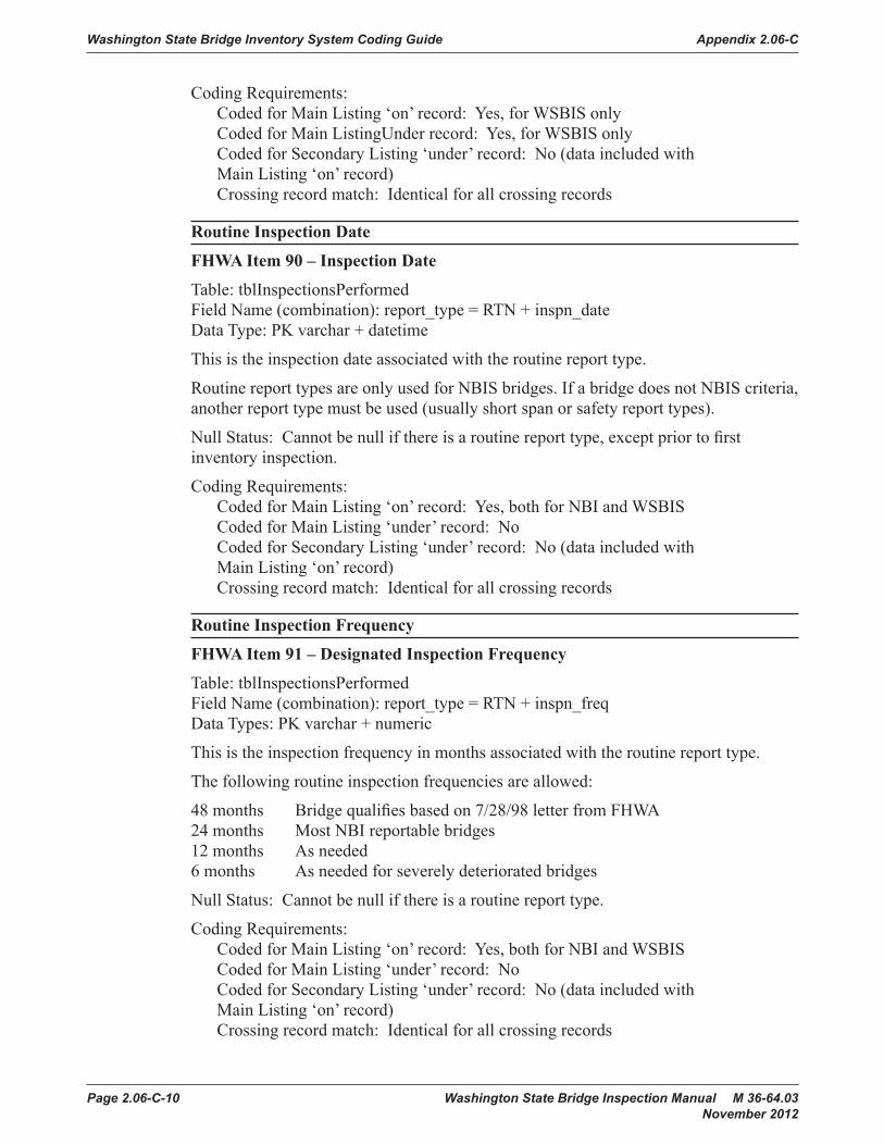
Washington State Bridge Inventory System Coding Guide Appendix 2.06-C
Page 2.06-C-10 Washington State Bridge Inspection Manual M 36-64.03 November 2012
Coding Requirements:Coded for Main Listing ‘on’ record: Yes, for WSBIS onlyCoded for Main ListingUnder record: Yes, for WSBIS onlyCoded for Secondary Listing ‘under’ record: No (data included with Main Listing ‘on’ record) Crossing record match: Identical for all crossing records
Routine Inspection Date
FHWA Item 90 – Inspection Date
Table: tblInspectionsPerformedField Name (combination): report_type = RTN + inspn_dateData Type: PK varchar + datetime
This is the inspection date associated with the routine report type.
Routine report types are only used for NBIS bridges. If a bridge does not NBIS criteria, another report type must be used (usually short span or safety report types).
Null Status: Cannot be null if there is a routine report type, except prior to first inventory inspection.
Coding Requirements:Coded for Main Listing ‘on’ record: Yes, both for NBI and WSBISCoded for Main Listing ‘under’ record: NoCoded for Secondary Listing ‘under’ record: No (data included with Main Listing ‘on’ record)Crossing record match: Identical for all crossing records
Routine Inspection Frequency
FHWA Item 91 – Designated Inspection Frequency
Table: tblInspectionsPerformedField Name (combination): report_type = RTN + inspn_freqData Types: PK varchar + numeric
This is the inspection frequency in months associated with the routine report type.
The following routine inspection frequencies are allowed:
48 months Bridge qualifies based on 7/28/98 letter from FHWA24 months Most NBI reportable bridges12 months As needed6 months As needed for severely deteriorated bridges
Null Status: Cannot be null if there is a routine report type.
Coding Requirements:Coded for Main Listing ‘on’ record: Yes, both for NBI and WSBISCoded for Main Listing ‘under’ record: NoCoded for Secondary Listing ‘under’ record: No (data included with Main Listing ‘on’ record)Crossing record match: Identical for all crossing records

Appendix 2.06-C Washington State Bridge Inventory System Coding Guide
Washington State Bridge Inspection Manual M 36-64.03 Page 2.06-C-11 November 2012
Fracture Critical Inspection Frequency
FHWA Item 92A – Critical Feature Inspection, Fracture Critical Details
Table: tblInspectionsPerformedField Name (combination): report_type = FC + inspn_freqData Types: PK varchar + numeric
This is the inspection frequency in months associated with the fracture critical report type.
The following fracture critical inspection frequencies are allowed:
24 months Most NBI reportable bridges12 months As needed6 months As needed for severely deteriorated bridges
Null Status: Cannot be null if there is a fracture critical report type.
Coding Requirements:Coded for Main Listing ‘on’ record: Yes, both for NBI and WSBISCoded for Main Listing ‘under’ record: NoCoded for Secondary Listing ‘under’ record: No (data included with Main Listing ‘on’ record)Crossing record match: Identical for all crossing records
NBI Commentary:WSBIS data is translated to match NBI format requirements in the NBI text file.
Fracture Critical Inspection Date
FHWA Item 93A – Critical Feature Inspection Date, Fracture Critical Details
Table: tblInspectionsPerformedField Name (combination): report_type = FC + inspn_dateData Type: PK varchar + datetime
This is the inspection date associated with the fracture critical report type.
Fracture critical report types are only used for NBIS bridges which are considered fracture critical. If a bridge does not meet NBIS criteria, another report type must be used.
Null Status: Cannot be null if there is a fracture critical report type, except prior to first inventory inspection.
Coding Requirements:Coded for Main Listing ‘on’ record: Yes, both for NBI and WSBISCoded for Main Listing ‘under’ record: NoCoded for Secondary Listing ‘under’ record: No (data included with Main Listing ‘on’ record)Crossing record match: Identical for all crossing records
NBI Commentary:WSBIS data is translated to match NBI format requirements in the NBI text file.

Washington State Bridge Inventory System Coding Guide Appendix 2.06-C
Page 2.06-C-12 Washington State Bridge Inspection Manual M 36-64.03 November 2012
Underwater Inspection Frequency
FHWA Item 92B – Critical Feature Inspection, Underwater Inspection
Table: tblInspectionsPerformedField Name (combination): report_type = UW + inspn_freqData Types: PK varchar + numeric
This is the inspection frequency in months associated with the underwater report type.
The following underwater inspection frequencies are allowed:
60 months Most bridges48 months as needed based on conditions36 months as needed based on conditions24 months as needed based on conditions, may be used with UW interim12 months as needed based on conditions, may be used with UW interim6 months as needed based on conditions, may be used with UW interim
Null Status: Cannot be null if there is a underwater report type.
Coding Requirements:Coded for Main Listing ‘on’ record: Yes, both for NBI and WSBISCoded for Main Listing ‘under’ record: Yes, for WSBIS onlyCoded for Secondary Listing ‘under’ record: No (data included with Main Listing ‘on’ record)Crossing record match: Identical for all crossing records
NBI Commentary:WSBIS data is translated to match NBI format requirements in the NBI text file.
Underwater Inspection Date
FHWA Item 93B – Critical Feature Inspection Date, Underwater Inspection
Table: tblInspectionsPerformedField Name (combination): report_type = UW + inspn_dateData Type: PK varchar + datetime
This is the inspection date associated with the underwater report type.
Null Status: Cannot be null if there is an underwater report type, except prior to first inventory inspection.
Coding Requirements:Coded for Main Listing ‘on’ record: Yes, both for NBI and WSBISCoded for Main Listing ‘under’ record: Yes, for WSBIS onlyCoded for Secondary Listing ‘under’ record: No (data included with Main Listing ‘on’ record)Crossing record match: Identical for all crossing records
NBI Commentary:WSBIS data is translated to match NBI format requirements in the NBI text file.
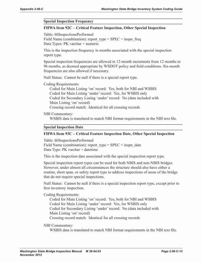
Appendix 2.06-C Washington State Bridge Inventory System Coding Guide
Washington State Bridge Inspection Manual M 36-64.03 Page 2.06-C-13 November 2012
Special Inspection Frequency
FHWA Item 92C – Critical Feature Inspection, Other Special Inspection
Table: tblInspectionsPerformedField Name (combination): report_type = SPEC + inspn_freqData Types: PK varchar + numeric
This is the inspection frequency in months associated with the special inspection report type.
Special inspection frequencies are allowed in 12-month increments from 12 months to 96 months, as deemed appropriate by WSDOT policy and field conditions. Six-month frequencies are also allowed if necessary.
Null Status: Cannot be null if there is a special report type.
Coding Requirements:Coded for Main Listing ‘on’ record: Yes, both for NBI and WSBISCoded for Main Listing ‘under’ record: Yes, for WSBIS onlyCoded for Secondary Listing ‘under’ record: No (data included with Main Listing ‘on’ record)Crossing record match: Identical for all crossing records
NBI Commentary:WSBIS data is translated to match NBI format requirements in the NBI text file.
Special Inspection Date
FHWA Item 93C – Critical Feature Inspection Date, Other Special Inspection
Table: tblInspectionsPerformedField Name (combination): report_type = SPEC + inspn_dateData Type: PK varchar + datetime
This is the inspection date associated with the special inspection report type.
Special inspection report types can be used for both NBIS and non-NBIS bridges. However, under almost all circumstances the structure should also have either a routine, short span, or safety report type to address inspections of areas of the bridge that do not require special inspections.
Null Status: Cannot be null if there is a special inspection report type, except prior to first inventory inspection.
Coding Requirements:Coded for Main Listing ‘on’ record: Yes, both for NBI and WSBISCoded for Main Listing ‘under’ record: Yes, for WSBIS onlyCoded for Secondary Listing ‘under’ record: No (data included with Main Listing ‘on’ record)Crossing record match: Identical for all crossing records
NBI Commentary:WSBIS data is translated to match NBI format requirements in the NBI text file.

Washington State Bridge Inventory System Coding Guide Appendix 2.06-C
Page 2.06-C-14 Washington State Bridge Inspection Manual M 36-64.03 November 2012
Inspector Initials
Table: tblInspectionsPerformedField Name: inspr_initialsData Type: varchar
These are the initials of the team leader whose certification number appears in the Inspector Certification Number.
Null Status: Cannot be null.
Coding Requirements:Coded for Main Listing ‘on’ record: Yes, for WSBIS onlyCoded for Main Listing ‘under’ record: Yes, for WSBIS onlyCoded for Secondary Listing ‘under’ record: No (data included with Main Listing ‘on’ record)Crossing record match: Identical for all crossing records
Inspector Certification Number
Table: tblInspectionsPerformedField Name: cert_noData Type: varchar
This is the certification number of the team leader at the bridge site performing the inspection for the designated report type.
Null Status: Cannot be null.
Coding Requirements:Coded for Main Listing ‘on’ record: Yes, for WSBIS only Coded for Main Listing ‘under’ record: Yes, for WSBIS onlyCoded for Secondary Listing ‘under’ record: No (data included with Main Listing ‘on’ record)Crossing record match: Identical for all crossing records
Co-Inspector Initials
Table: tblInspectionsPerformedField Name: co_inspr_initialsData Type: varchar
These are the initials of the individual who assisted the team leader in performing the inspection for the designated report type.
Null Status: May be null only for Damage, Informational and Inventory report types.
Coding Requirements:Coded for Main Listing ‘on’ record: Yes, for WSBIS onlyCoded for Main Listing ‘under’ record: Yes, for WSBIS onlyCoded for Secondary Listing ‘under’ record: No (data included with Main Listing ‘on’ record)Crossing record match: Identical for all crossing records

Appendix 2.06-C Washington State Bridge Inventory System Coding Guide
Washington State Bridge Inspection Manual M 36-64.03 Page 2.06-C-15 November 2012
Inspection Hours
Table: tblInspectionsPerformedField Name: inspn_hoursData Type: numeric
This is the total number of inspection hours (to the nearest half hour) that the inspection team spent on the bridge while performing an inspection on the designated report type.
Null Status: Leave blank only for Informational and Inventory report types.
Coding Requirements:Coded for Main Listing ‘on’ record: Yes, for WSBIS onlyCoded for Main Listing ‘under’ record: Yes, for WSBIS onlyCoded for Secondary Listing ‘under’ record: No (data included with Main Listing ‘on’ record)Crossing record match: Identical for all crossing records
Inspection Overtime Hours
Table: tblInspectionsPerformedField Name: inspn_overtime_hoursData Type: numeric
This is the total number of overtime inspection hours (to the nearest half hour) that the inspection team spent on the bridge while performing an inspection on the designated report type.
Null Status: Leave blank only for Informational and Inventory report types.
Coding Requirements:Coded for Main Listing ‘on’ record: Yes, for WSBIS onlyCoded for Main Listing ‘under’ record: Yes, for WSBIS onlyCoded for Secondary Listing ‘under’ record: No (data included with Main Listing ‘on’ record)Crossing record match: Identical for all crossing records

Washington State Bridge Inventory System Coding Guide Appendix 2.06-C
Page 2.06-C-16 Washington State Bridge Inspection Manual M 36-64.03 November 2012

Appendix 2.06-C Washington State Bridge Inventory System Coding Guide
Washington State Bridge Inspection Manual M 36-64.03 Page 2.06-C-17 November 2012
Adequacy Appraisals
WSBIS Items 657, 658, 659, 661, and 662
FHWA Items 67, 68, 69, 71, and 72
The items in the Appraisal Section are used to evaluate a bridge in relation to the level of service which it provides on the highway system of which it is a part. The structure will be compared to a new one which is built to current standards for that particular type of road as further defined in this section except for WSBIS Item 661 - Approach Roadway Alignment. See WSBIS Item 661 for special criteria for rating that item.
WSBIS Items 657, 658, 659, 661, and 662 will be coded with a 1-digit code that indicates the appraisal rating for the item. The ratings and codes are as follows:
Code Description9 Not applicable8 Superior or equal to present desirable criteria7 Better than present minimum criteria6 Equal to present minimum criteria5 Better than minimum tolerable limits4 Meets minimum tolerable limits to be left in place as is3 Basically intolerable requiring high priority corrective action2 Basically intolerable requiring high priority replacement1 This value of rating code not used0 Bridge closed
WSBIS Items 657, 658, 659 are calculated automatically based on other coded items.
Completed bridges not yet opened to traffic, if rated, shall be appraised as if open to traffic. Design values, for example ADT, shall be used for the evaluation. The data provided will include a code of G for WSBIS Item 293 - Structure Open, Posted, or Closed to Traffic.
NBI Commentary:WSBIS uses the 9 code to indicate “Not applicable”, which is translated to N when reported to the NBI. WSBIS used code 8 for “Superior or equal to present desirable criteria”.
WSBIS Item 657 Structural Evaluation
FHWA Item 67 Structural Evaluation
Table: tblInspectionReportsField Name: structural_adqcyData Type: varchar
This item is calculated automatically and cannot be edited.
Structural Evaluation rates the adequacy of the structure’s condition, taking into account any major structural deficiencies. This rating is based on the overall condition of the superstructure, substructure, the inventory rating, and the ADT.

Washington State Bridge Inventory System Coding Guide Appendix 2.06-C
Page 2.06-C-18 Washington State Bridge Inspection Manual M 36-64.03 November 2012
Table WSBIS-657 explains how the inventory rating may further lower this code. The code for this item is no higher than the lowest of the condition codes for Superstructure Overall, Substructure Condition, or Culvert Condition.
ADT Structural Adequacy Appraisal
Rating Code
0-500 501-5000 >5000
Inventory Rating HS Truck (Tons)
Not Applicable 936 36 36 831 31 31 723 25 27 618 20 22 512 14 18 4
Inventory rating less than value in rating code of 4 and requiring corrective action.
3
Inventory rating is less than above and bridge requires replacement, WSBIS Item 844 is coded 31 or 32.
2
Bridge is closed and requires replacement. 0
Structural Adequacy Appraisal RatingTable WSBIS-657
Null Status: Cannot be null if bridge has an on record, must be null if the bridge does not have an on record.
Coding Requirements:Coded for Main Listing ‘on’ record: Yes, both for NBI and WSBISCoded for Main Listing ‘under’ record: NoCoded for Secondary Listing ‘under’ record: No (data included with Main Listing ‘on’ record)Crossing record match: Identical for all crossing records
WSBIS Item 658 – Deck Geometry
FHWA Item 68 – Deck Geometry
Table: tblInspectionReportsField Name: deck_geometry_aprslData Type: varchar
This item is calculated automatically and cannot be edited.
The level of service provided by the bridge is evaluated with respect to the highway system of which it is a part. This appraisal is based on the number of traffic lanes, the curb-to-curb width, the minimum vertical clearance over the bridge deck, the ADT, and the federal functional classification.

Appendix 2.06-C Washington State Bridge Inventory System Coding Guide
Washington State Bridge Inspection Manual M 36-64.03 Page 2.06-C-19 November 2012
The following tables explain how the values are determined with respect to the highway system of which the bridge is a part. The lowest code determined from the tables is used.
Curb-to-Curb Bridge Roadway Width (in feet) Deck Geometry Appraisal
Rating CodeAverage Daily Traffic (ADT) (both directions)
0-100 101-400 401-1000 1001-2000 2001-5000 >5000Not Applicable 9
>32 >36 >40 >44 >44 >44 828 32 36 40 44 44 724 28 30 34 40 44 620 24 26 28 34 38 518 20 22 24 28 32(28) 416 18 20 22 26 30(26) 3
Bridge is open and has a width less than required for a rating code of 3 and WSBIS Item 844 is coded 31.
2
Bridge is closed. 0Notes:1. For bridges longer than 200 feet, use the values shown in parentheses.2. Use the lower rating code for roadway widths between those shown.3. For bridges with 3 or more undivided lanes of 2-way traffic, use Table WSBIS-658C under the column Number of Lanes
(Other Roadways).
Deck Geometry Appraisal Rating 2-Lane Bridge With 2-Way TrafficTable WSBIS-658A
Curb-to-Curb Bridge Roadway Width (in feet) Deck Geometry Appraisal
Rating CodeAverage Daily Traffic (ADT) (both directions)
0-100 >100Not Applicable 9
15’11” - 815 - 714 - 613 - 512 - 411 15’11” 3
Bridge is open and has a width less than required for a rating code of 3 and WSBIS Item 844 is coded 31.
2
Bridge is closed. 0Notes:1. Use the lower rating code for roadway widths between those shown.2. All single lane bridges with a deck width less than 16 feet and an ADT > 100 should be rated
at 3 or below.
Deck Geometry Appraisal Rating 1-Lane Bridge With 2-Way TrafficTable WSBIS-658B

Washington State Bridge Inventory System Coding Guide Appendix 2.06-C
Page 2.06-C-20 Washington State Bridge Inspection Manual M 36-64.03 November 2012
Curb-to-Curb Bridge Roadway Width (in feet) Two or More Lanes in Each Direction
Deck Geometry Appraisal
Rating Code
Number of Lanes (Interstate)
Number of Lanes (Other Roadways)
2 Lanes > 2 Lanes 2 Lanes > 2 LanesNot Applicable 9
> 42 > 12N + 24 > 42 > 12N + 18 840 12N + 20 38 12N + 15 738 12N + 16 36 12N + 12 636 12N + 14 33 11N + 10 5
34 (29) 11N + 12 (11N + 7) 30 11N + 6 433 (28) 11N + 11 (11N + 6) 27 11N + 5 3
Bridge is open and has a width less than required for rating code of 3 and WSBIS Item 844 is coded 31.
2
Bridge is closed. 0Notes:1. N = Number of traffic lanes.2. Use the lower rating code for roadway widths between those shown.3. For bridges longer than 200 feet, use the values shown in parentheses.
Deck Geometry Appraisal Rating Bridges With 2-Way TrafficTable WSBIS-658C
Bridge/Ramp Width (in feet) Deck Geometry Appraisal
Rating CodeNumber of Lanes
1 Lane > 1 LaneNot Applicable 9
> 26 > 12N + 12 824 12N + 10 722 12N + 8 620 12N + 6 518 12N + 4 416 12N + 2 3
Bridge is open and has deck width less than required for a rating code of 3 and WSBIS Item 844 is coded 31.
2
Bridge is closed. 0Notes:1. N = Number of traffic lanes.2. Use the lower rating code for a roadway width between those shown.
Deck Geometry Appraisal Rating Bridges or Ramps With 1-Way TrafficTable WSBIS-658D

Appendix 2.06-C Washington State Bridge Inventory System Coding Guide
Washington State Bridge Inspection Manual M 36-64.03 Page 2.06-C-21 November 2012
Functional Class Deck Geometry Appraisal
Rating Code
Interstate and Other Freeway Other Principal and Minor Arterials
Major and Minor Collectors and
LocalsDesignated
Routes*Undesignated
Routes*Minimum Vertical Clearance
Not Applicable 9> 17′0″ > 16′0″ > 16′6″ > 16′6″ 816′9″ 15′6″ 15′6″ 15′6″ 716′6″ 14′6″ 14′6″ 14′6″ 615′9″ 14′3″ 14′3″ 14′3″ 515′0″ 14′0″ 14′0″ 14′0″ 4
Vertical clearance is less than value for rating of 4; corrective action is required. 3Vertical clearance is less than value for rating of 4 and WSBIS Item 844 is coded 31; replacement is required.
2
Bridge is closed. 0Notes:*Use the first column (Designated Routes) for all routes except designated routes in urban areas where there is an alternative interstate or freeway facility with a minimum clearance of at least 16′0″. Use the second column (Undesignated Routes) for all undesignated interstate or freeway facilities.1. Use the lower rating code for any vertical clearance measurements between those shown.
Deck Geometry Appraisal RatingTable WSBIS-658E
Null Status: Cannot be null.
Coding Requirements:Coded for Main Listing ‘on’ record: Yes, both for NBI and WSBISCoded for Main Listing ‘under’ record: NoCoded for Secondary Listing ‘under’ record: No (data included with Main Listing ‘on’ record)Crossing record match: Identical for all crossing records
WSBIS Item 659 – Underclearances
FHWA Item 69 – Underclearances, Vertical and Horizontal
Table: tblInspectionReportsField Name: underclrnc_aprslData Type: varchar
This item is calculated automatically and cannot be edited.
This appraisal is based on the vertical and lateral underclearances beneath the bridge as related to the federal functional classification of the roadway carried beneath the bridge. If the bridge is not over a highway or a railroad, the field will be set to 9.

Washington State Bridge Inventory System Coding Guide Appendix 2.06-C
Page 2.06-C-22 Washington State Bridge Inspection Manual M 36-64.03 November 2012
Minimum vertical underclearance, minimum lateral underclearance on right, and minimum lateral underclearance on left are used to evaluate this item.
See the following tables for an explanation of how the values are calculated.
The functional classification used in the tables is for the route under the bridge. If no ‘under’ record exits, it is assumed that the route under the bridge is a major or minor collector or a local road for the purpose of using the tables.
Functional ClassUnder-
clearance Adequacy Appraisal
Rating Code
Interstate and Other Freeway Other Principal and Minor Arterials
Major and Minor
Collectors and Locals
RailroadsDesignated Routes*
Undesignated Routes*
Minimum Vertical UnderclearanceNot Applicable 9
> 17′0″ > 16′0″ > 16′6″ > 16′6″ > 23′0″ 816′9″ 15′6″ 15′6″ 15′6″ 22′6″ 716′6″ 14′6″ 14′6″ 14′6″ 22′0″ 615′9″ 14′3″ 14′3″ 14′3″ 21′0″ 515′0″ 14′0″ 14′0″ 14′0″ 20′0″ 4
Vertical Clearance is less than value for rating of 4; corrective action is required. 3Vertical clearance is less than value for rating of 4 and WSBIS Item 844 is coded 31; replacement is required.
2
Bridge closed. 0Notes:*Use the first column (Designated Routes) for all routes except designated routes in urban areas where there is an alternative interstate or freeway facility with a minimum clearance of at least 16′0″. Use the second column (Undesignated Routes) for all undesignated interstate or freeway facilities.1. Use the lower rating code for any vertical clearance measurements between those shown.
Vertical Underclearance Adequacy Appraisal RatingTable WSBIS-659A

Appendix 2.06-C Washington State Bridge Inventory System Coding Guide
Washington State Bridge Inspection Manual M 36-64.03 Page 2.06-C-23 November 2012
Functional ClassUnder-
clearance Adequacy Appraisal
Rating Code
1-Way Traffic 2-Way Traffic
RailroadsPrincipal Arterials (Interstate, etc.) Other
Principal and Minor Arterials
Major and Minor
Collectors and Locals
Main Line Ramp
Lt. Rt. Lt. Rt.
Minimum Lateral Underclearance (Feet)Not Applicable 9
> 30 > 30 > 4 > 10 > 30 > 12 > 20 818 21 3 9 21 11 17 76 12 2 8 12 10 14 65 11 2 6 10 8 11 54 10 2 4 8 6 8 4
Underclearance is less than value for rating of 4; corrective action is required. 3Underclearance is less than value for rating of 4 and WSBIS Item 844 is coded 31; replacement is required.
2
Bridge is closed. 0Notes:1. Use the lower rating code for any underclearance measurements between those shown.2. Use the value from the Right Ramp column to determine the rating code when acceleration or deceleration lanes
or ramps are provided under 2-way traffic.
Lateral Underclearance Adequacy Appraisal RatingTable WSBIS-659B
Null Status: Cannot be null.
Coding Requirements:Coded for Main Listing ‘on’ record: Yes, both for NBI and WSBISCoded for Main Listing ‘under’ record: Yes, WSBIS onlyCoded for Secondary Listing ‘under’ record: No (data included with Main Listing ‘on’ record)Crossing record match: Identical for all crossing records
WSBIS Item 660 – Operating Level
FHWA Item 70 – Bridge Posting
Table: tblInspectionReportsField Name: safe_load_codeData Type: varchar
The National Bridge Inspection Standards require the posting of load limits only if the maximum legal load configurations in the State exceeds the load permitted under the operating rating. If the load capacity at the operating rating is such that posting is required, this item shall be coded 4 or less. If no posting is required at the operating rating, this item shall be coded 5.

Washington State Bridge Inventory System Coding Guide Appendix 2.06-C
Page 2.06-C-24 Washington State Bridge Inspection Manual M 36-64.03 November 2012
This item evaluates the load capacity of a bridge in comparison to the State legal load. It differs from WSBIS Item 657 - Structural Evaluation in that WSBIS Item 657 uses WSBIS Item 555 - Inventory Rating, while the bridge posting requirement is based on WSBIS Item 552 - Operating Rating.
Although posting a bridge for load-carrying capacity is required only when the maximum legal load exceeds the operating rating, highway agencies may choose to post at a lower level. This posting practice may appear to produce conflicting coding when WSBIS Item 293 - Structure Open, Posted or Closed to Traffic is coded to show the bridge as actually posted at the site and WSBIS Item 660 - Bridge Posting is coded as bridge posting is not required. Since different criteria are used for coding these 2 items, this coding is acceptable and correct when the highway agency elects to post at less than the operating rating. WSBIS Item 660 shall be coded 4 or less only if the legal load of the State exceeds that permitted under the operating rating.
The use or presence of a temporary bridge affects the coding. The actual operating rating of the temporary bridge should be used to determine this item. However the highway agency may choose to post at a lower level. This also applies to bridges shored up or repaired on a temporary basis.
The legal load that creates the lowest value shall be coded.
Code Relationship of Operating Rating to Maximum Legal Load5 Equal to or above legal loads4 0.1 – 9.9% below legal load (posting required)3 10.0 – 19.9% below legal load (posting required)2 20.0 – 29.9% below legal load (posting required)1 30.0 – 39.9% below legal load (posting required)0 > 39.9% below legal load (posting required)
Null Status: Cannot be null.
Coding Requirements:Coded for Main Listing ‘on’ record: Yes, both for NBI and WSBISCoded for Main Listing ‘under’ record: No`Coded for Secondary Listing ‘under’ record: No (data included with Main Listing ‘on’ record)Crossing record match: Identical for all crossing records
WSBIS Item 661 – Alignment
FHWA Item 72 – Approach Roadway Alignment
Table: tblInspectionReportsField Name: alignment_aprslData Type: varchar
Code the rating based on the adequacy of the approach roadway alignment. This item identifies those bridges which do not function properly or adequately due to the alignment of the approaches. It is not intended that the approach roadway alignment be compared to current standards but rather to the existing highway alignment. This concept differs from other appraisal evaluations. The establishment of set criteria to

Appendix 2.06-C Washington State Bridge Inventory System Coding Guide
Washington State Bridge Inspection Manual M 36-64.03 Page 2.06-C-25 November 2012
be used at all bridge sites is not appropriate for this item. The basic criteria is how the alignment of the roadway approaches to the bridge relate to the general highway alignment for the section of highway the bridge is on.
Speed reductions necessary because of structure width and not alignment shall not be considered in evaluating this item.
Code Description9 Not applicable (non-vehicular traffic use).8 No reduction in speed required for vehicle as it approaches the bridge.6 Minor reduction in speed required for vehicle(less than 10 mph) as it approaches
the bridge.3 Horizontal or vertical curvature of approach roadway requires substantial
reduction in the speed of vehicle (10 mph or greater) as it approaches the bridge.
Null Status: Cannot be null if bridge has an on record, must be null if the bridge does not have an on record.
Coding Requirements:Coded for Main Listing ‘on’ record: Yes, both for NBI and WSBISCoded for Main Listing ‘under’ record: NoCoded for Secondary Listing ‘under’ record: No (data included with Main Listing ‘on’ record)Crossing record match: Identical for all crossing records
NBI Commentary:This coding guide has eliminated several intermediate codes available in the NBI coding guide.
WSBIS Item 662 – Waterway
FHWA Item 71 – Waterway Adequacy
Table: tblInspectionReportsField Name: waterway_aprslData Type: varchar
This item appraises the waterway opening with respect to passage of flow through the bridge. Site conditions may warrant somewhat higher or lower ratings than indicated by the table (e.g., flooding of an urban area due to a restricted bridge opening).
Where overtopping frequency information is available, the descriptions given in the table for chance of overtopping mean the following:
Remote – greater than 100 yearsSlight – 11 to 100 yearsOccasional – 3 to 10 yearsFrequent – less than 3 years
Adjectives describing traffic delays mean the following:
Insignificant – Minor inconvenience. Highway passable within hoursSignificant – Traffic delays of up to several days.Severe – Long term delays to traffic

Washington State Bridge Inventory System Coding Guide Appendix 2.06-C
Page 2.06-C-26 Washington State Bridge Inspection Manual M 36-64.03 November 2012
WSBIS Item 487 – Functional Class
Description
01, 11, 12 02, 06, 07, 14, 16, 17 08, 09, 19
Waterway Adequacy Appraisal Rating Code
9 9 9 Bridge not over a waterway8 8 8 Bridge deck and roadway approaches above flood water elevations.
Remote chance of overtopping.ORBridge deck above roadway approaches. Slight chance of overtopping roadway approaches.
6 6 7 Slight chance of overtopping bridge deck and roadway approaches.4 5 6 Bridge deck above roadway approaches. Occasional overtopping
of roadway approaches with insignificant traffic delays3 4 5 Bridge deck above roadway approaches. Occasional overtopping
of roadway approaches with significant traffic delays.2 3 4 Occasional overtopping of bridge deck and roadway approaches
with significant traffic delays.2 2 3 Frequent overtopping of bridge deck and roadway approaches with
significant traffic delays.2 2 2 Occasional or frequent overtopping of bridge deck and roadway
approaches with severe traffic delays.0 0 0 Bridge closed.
Waterway Adequacy Appraisal RatingTable WSBIS-662
Inspection report comments are required when the condition is coded 7 or less.
Null Status: Cannot be null.
Coding Requirements:Coded for Main Listing ‘on’ record: Yes, both for NBI and WSBISCoded for Main Listing ‘under’ record: Yes, WSBIS onlyCoded for Secondary Listing ‘under’ record: No (data included with Main Listing ‘on’ record)Crossing record match: Identical for all crossing records
NBI Commentary:WSBIS uses the 9 code to indicate “Not applicable”, which is translated to N when reported to the NBI.

Appendix 2.06-C Washington State Bridge Inventory System Coding Guide
Washington State Bridge Inspection Manual M 36-64.03 Page 2.06-C-27 November 2012
Condition Ratings
WSBIS Items 663, 671, 676, 677, and 678
FHWA Items 58, 59, 60, 61, and 62
In order to promote uniformity between bridge inspectors, these guidelines will be used to rate and code WSBIS Items 663, 671, 676, 677, and 678.
Condition ratings are used to describe the existing, in-place bridge as compared to the as-built condition. Evaluation is for the materials related, physical condition of the deck, superstructure, and substructure components of a bridge. The condition evaluation of channels and channel protection and culverts is also included. Condition codes are properly used when they provide an overall characterization of the general condition of the entire component being rated. Conversely, they are improperly used if they attempt to describe localized or nominally occurring instances of deterioration or disrepair. Correct assignment of a condition code must, therefore, consider both the severity of the deterioration or disrepair and the extent to which it is widespread throughout the component being rated.
The load-carrying capacity will not be used in evaluating condition items. The fact that a bridge was designed for less than current legal loads and may be posted shall have no influence upon condition ratings.
Portions of bridges that are being supported or strengthened by temporary members will be rated based on their actual condition; that is, the temporary members are not considered in the rating of the item. (See WSBIS Item 289 - Temporary Structure Designation for the definition of a temporary bridge.)
Completed bridges not yet opened to traffic, if rated, shall be coded as if open to traffic.

Washington State Bridge Inventory System Coding Guide Appendix 2.06-C
Page 2.06-C-28 Washington State Bridge Inspection Manual M 36-64.03 November 2012
The following general condition ratings shall be used as a guide in evaluating WSBIS Items 663, 671 and 676:
Code Description9 Not applicable8 Very good condition – no problems noted.7 Good condition – some minor problems.6 Satisfactory condition – structural elements show some minor deterioration.5 Fair condition – all primary structural elements are sound but may have minor
section loss, cracking, spalling or scour.4 Poor condition – advanced section loss, deterioration, spalling or scour.3 Serious condition – loss of section, deterioration, spalling or scour have seriously
affected primary structural components. Local failures are possible. Fatigue cracks in steel or shear cracks in concrete may be present.
2 Critical condtion – advanced deterioration of primary structural elements. Fatigue cracks in steel or shear cracks in concrete may be present or scour may have removed substructure support. Unless closely monitored it may be necessary to close the bridge until corrective action is taken.
1 “Imminent” failure condition – major deterioration or section loss present in critical structural components or obvious vertical or horizontal movement affecting structure stability. Bridge is closed to traffic but corrective action may put back in light service.
0 Failed condition – out of service beyond corrective action.
NBI Commentary:WSBIS uses the 9 code to indicate “Not applicable”, which is translated to N when reported to the NBI. WSDOT uses condition code 8 for all cases where a bridge is in “Excellent” or “Very good” condition.
WSBIS Item 663 – Overall Deck Condition
FHWA Item 58 – Deck
Table: tblInspectionReportsField Name: deck_overall_condData Type: varchar
This item describes the overall condition rating of the deck. Rate and code the condition in accordance with the above general condition ratings. Code N for culverts and other structures without decks (e.g., filled arch bridges).
Deck condition ratings are also associated with deck BMS elements as shown in WSBIM Chapter 4. If the inspector determines a deck code should be different from that indicated in Chapter 4 guidance, an explanation for this difference should be noted in the inspection report.
Concrete decks should be inspected for cracking, scaling, spalling, leaching, chloride contamination, potholing, delamination, and full or partial depth failures. Steel grid decks should be inspected for broken welds, broken grids, section loss, and growth of filled grids from corrosion. Timber decks should be inspected for splitting, crushing, fastener failure, and deterioration from rot.

Appendix 2.06-C Washington State Bridge Inventory System Coding Guide
Washington State Bridge Inspection Manual M 36-64.03 Page 2.06-C-29 November 2012
The condition of the wearing surface/protective system, joints, expansion devices, curbs, sidewalks, parapets, fascias, bridge rail, and scuppers shall not be considered in the overall deck evaluation. However, their condition should be noted on the inspection form under the appropriate BMS element note.
Decks integral with the superstructure will be rated as a deck only and not how they may influence the superstructure rating (for example, rigid frame, slab, deck girder or T-beam, voided slab, box girder, etc.). Similarly, the superstructure of an integral decktype bridge will not influence the deck rating.
Inspection report comments are required when the condition is coded 5 or less.
Null Status: Cannot be null.
Coding Requirements:Coded for Main Listing ‘on’ record: Yes, both for NBI and WSBISCoded for Main Listing ‘under’ record: Yes, for WSBIS onlyCoded for Secondary Listing ‘under’ record: No (data included with Main Listing ‘on’ record)Crossing record match: Identical for all crossing records
NBI Commentary:This item has been modified to incorporate BMS deck element condition states into the coding criteria.
WSBIS Item 671 – Superstructure Overall
FHWA Item 59 – Superstructure
Table: tblInspectionReportsField Name: superstructure_condData Type: varchar
This item describes the physical condition of all structural members. Rate and code the condition in accordance with the previously described general condition ratings. Code N for all culverts.
The structural members should be inspected for signs of distress which may include cracking, deterioration, section loss, and malfunction and misalignment of bearings.
The condition of bearings, joints, paint system, etc., shall not be included in this rating, except in extreme situations, but should be noted on the inspection form under the appropriate BMS element note.
On bridges where the deck is integral with the superstructure, the superstructure condition rating may be affected by the deck condition. The resultant superstructure condition rating may be lower than the deck condition rating where the girders have deteriorated or been damaged.
Fracture critical components should receive careful attention because failure could lead to collapse of a span or the bridge.
Inspection report comments are required when the condition is coded 5 or less.

Washington State Bridge Inventory System Coding Guide Appendix 2.06-C
Page 2.06-C-30 Washington State Bridge Inspection Manual M 36-64.03 November 2012
Null Status: Cannot be null.
Coding Requirements:Coded for Main Listing ‘on’ record: Yes, both for NBI and WSBISCoded for Main Listing ‘under’ record: Yes, for WSBIS onlyCoded for Secondary Listing ‘under’ record: No (data included with Main Listing ‘on’ record)Crossing record match: Identical for all crossing records
WSBIS Item 675 – Number of Utilities
Table: tblInspectionReportsField Name: utilities_qtyData Type: varchar
This field indicates the number of franchise utilities attached to the bridge. Utilities include, but are not limited to, water pipes, sewer lines, telephone lines, power lines, and gas lines. Conduit for electricity used on the bridge is not considered a utility. A conduit cluster (e.g., a telephone cluster) is considered one utility. This field is not used to evaluate the condition of utilities on the bridge, only the number of utilities present. If more than nine utilities are attached to the bridge, code 9. If there are no utilities, code Ø.
Null Status: Null only when there is no on record associated with the bridge.
Coding Requirements:Coded for Main Listing ‘on’ record: Yes, for WSBIS onlyCoded for Main Listing ‘under’ record: NoCoded for Secondary Listing ‘under’ record: No (data included with Main Listing ‘on’ record)Crossing record match: Identical for all crossing records
WSBIS Item 676 – Substructure Condition
FHWA Item 60 – Substructure
Table: tblInspectionReportsField Name: substructure_condData Type: varchar
This item describes the physical condition of piers, abutments, piles, fenders, footings, or other components. Rate and code the condition in accordance with the previously described general condition ratings. Code N for all culverts.
All substructure elements should be inspected for visible signs of distress including evidence of cracking, section loss, settlement, misalignment, scour, collision damage, and corrosion.
The substructure condition rating shall be made independent of the deck and superstructure.

Appendix 2.06-C Washington State Bridge Inventory System Coding Guide
Washington State Bridge Inspection Manual M 36-64.03 Page 2.06-C-31 November 2012
Integral-abutment wingwalls to the first construction or expansion joint shall be included in the evaluation. For non-integral superstructure and substructure units, the substructure shall be considered as the portion below the bearings. For structures where the substructure and superstructure are integral, the substructure shall be considered as the portion below the superstructure.
In all cases, if WSBIS Item 680 - Scour is 2 or less, WSBIS Item 676 - Substructure shall be coded the same.
Inspection report comments are required when the condition is coded 5 or less.
Null Status: Cannot be null.
Coding Requirements:Coded for Main Listing ‘on’ record: Yes, both for NBI and WSBISCoded for Main Listing ‘under’ record: Yes, for WSBIS onlyCoded for Secondary Listing ‘under’ record: No (data included with Main Listing ‘on’ record)Crossing record match: Identical for all crossing records
NBI Commentary:This item has been modified based on an April 27, 2001 FHWA memo regarding FHWA Items 60 and 113 (WSBIS Items 676 and 680). This memo is not available at the FHWA website, but the change is also noted in the 6/2011 errata document available at www.fhwa.dot.gov/bridge/errata.pdf.
WSBIS Item 677 – Channel Protection
FHWA Item 61 – Channel and Channel Protection
Table: tblInspectionReportsField Name: channel_protData Type: varchar
This item describes the physical conditions associated with the flow of water through the bridge such as stream stability and the condition of the channel, riprap, slope protection, or stream control devices including spur dikes. The inspector should be particularly concerned with visible signs of excessive water velocity which may affect undermining of slope protection, erosion of banks, and realignment of the stream. Accumulation of drift and debris on the superstructure and substructure should be noted on the inspection form but not included in the condition rating.
Inspection report comments are required when the condition is coded 7 or less. Note that a bridge with no scour potential (piles founded or on bedrock) can have a very low channel rating based on a threat to the approach fill. In this situation this code is the only way to flag the problem. Also note that roadway embankment erosion due to bridge or roadway runoff is NOT included in this field. These issues are addressed in the abutment BMS field.

Washington State Bridge Inventory System Coding Guide Appendix 2.06-C
Page 2.06-C-32 Washington State Bridge Inspection Manual M 36-64.03 November 2012
Rate and code the condition in accordance with the previously described general condition ratings and the following descriptive codes:
Code Description9 Not applicable. Use when bridge is not over a waterway (channel).8 There are no noticeable or noteworthy deficiencies. Banks are protected or well
vegetated. River control devices such as spur dikes and embankment protection are not required or are in a stable condition.
7 Bank protection is in need of minor repairs. River control devices and embankment protection have a little minor damage. Banks and/or channel have minor amounts of drift.
6 Bank is beginning to slump. River control devices and embankment protection have widespread minor damage. There is minor stream bed movement evident. Debris is restricting the channel slightly.
5 Bank protection is being eroded. River control devices and/or embankment have major damage. Trees and brush restrict the channel.
4 Bank and embankment protection is severely undermined. River control devices have severe damage. Large deposits of debris are in the channel.
3 Bank protection has failed. River control devices have been destroyed. Stream bed aggradation, degradation or lateral movement has changed the channel to now threaten the bridge and/or approach roadway.
2 The channel has changed to the extent the bridge is near a state of collapse.1 Bridge closed because of channel failure. Corrective action may put back in
light service.0 Bridge closed because of channel failure. Replacement necessary.
Null Status: Cannot be null.
Coding Requirements:Coded for Main Listing ‘on’ record: Yes, both for NBI and WSBISCoded for Main Listing ‘under’ record: Yes, for WSBIS onlyCoded for Secondary Listing ‘under’ record: No (data included with Main Listing ‘on’ record)Crossing record match: Identical for all crossing records

Appendix 2.06-C Washington State Bridge Inventory System Coding Guide
Washington State Bridge Inspection Manual M 36-64.03 Page 2.06-C-33 November 2012
WSBIS Item 678 – Culvert Condition
FHWA Item 62 – Culverts
Table: tblInspectionReportsField Name: culvert_condData Type: varchar
This item evaluates the alignment, settlement, joints, structural condition, scour, and other items associated with culverts. The rating code is intended to be an overall condition evaluation of the culvert. Integral wingwalls to the first construction or expansion joint shall be included in the evaluation.
Inspection report comments are required when the condition is coded 5 or less. Additional guidelines:
• Concrete three-sided rigid frames carrying deck traffic or with roadway fill less than A/2 are coded as bridges.
• Concrete three-sided rigid frames with roadway fill more than A/2 on them, are coded as culverts.
• Concrete Boxes with or without roadway fill are coded as culverts.
• Steel Pipe Arches are coded as culverts.
• For Culverts, code Deck, Superstructure and Substructure (WSBIS Items 663, 671, and 676) as “9”.
• Code Bridge Rails and Transitions (WSBIS Items 684 and 685) “N” if there is sufficient roadway fill that there is no attachment to the structure. Guardrails and Terminals (WSBIS Items 686 and 687) are to be coded “0” or “1” as appropriate.
• When inspecting culverts, document the depth of the fill on both ends of the culvert. For cases where there is a significant amount of fill compared to the span length of the culvert, or total length of culverts where there are multiple barrels, estimate and document the depth of fill.

Washington State Bridge Inventory System Coding Guide Appendix 2.06-C
Page 2.06-C-34 Washington State Bridge Inspection Manual M 36-64.03 November 2012
Rate and code the condition in accordance with the previously described general condition ratings and the following descriptive codes:
Code Description9 Not applicable. Use if structure is not a culvert.8 No noticeable or noteworthy deficiencies which affect the condition of the culvert.
Insignificant scrape marks caused by drift.7 Shrinkage cracks, light scaling, and insignificant spalling which does not expose
reinforcing steel. Insignificant damage caused by drift with no misalignment and not requiring corrective action. Some minor scouring has occurred near curtain walls, wingwalls, or pipes. Metal culverts have a smooth symmetrical curvature with superficial corrosion and no pitting.
6 Deterioration or initial disintegration, minor chloride contamination, cracking with some leaching, or spalls on concrete or masonry walls and slabs. Local minor scouring at curtain walls, wingwalls, or pipes. Metal culverts have a smooth curvature, non-symmetrical shape, significant corrosion or moderate pitting.
5 Moderate to major deterioration or disintegration, extensive cracking and leaching, or spalls on concrete or masonry walls and slabs. Minor settlement or misalignment. Noticeable scouring or erosion at curtain walls, wingwalls, or pipes. Metal culverts have significant distortion and deflection in one section, significant corrosion or deep pitting.
4 Large spalls, heavy scaling, wide cracks, considerable efflorescence, or opened construction joint permitting loss of backfill. Considerable settlement or misalignment. Considerable scouring or erosion at curtain walls, wingwalls or pipes. Metal culverts have significant distortion and deflection throughout, extensive corrosion or deep pitting.
3 Any condition described in Code 4 but which is excessive in scope. Severe movement or differential settlement of the segments, or loss of fill. Holes may exist in walls or slabs. Integral wingwalls nearly severed from culvert. Severe scour or erosion at curtain walls, wingwalls or pipes. Metal culverts have extreme distortion and deflection in one section, extensive corrosion, or deep pitting with scattered perforations.
2 Integral wingwalls collapsed, severe settlement of roadway due to loss of fill. Section of culvert may have failed and can no longer support embankment. Complete undermining at curtain walls and pipes. Corrective action required to maintain traffic. Metal culverts have extreme distortion and deflection throughout with extensive perforations due to corrosion.
1 Bridge closed – corrective action may put back in light service.0 Bridge closed – replacement necessary.
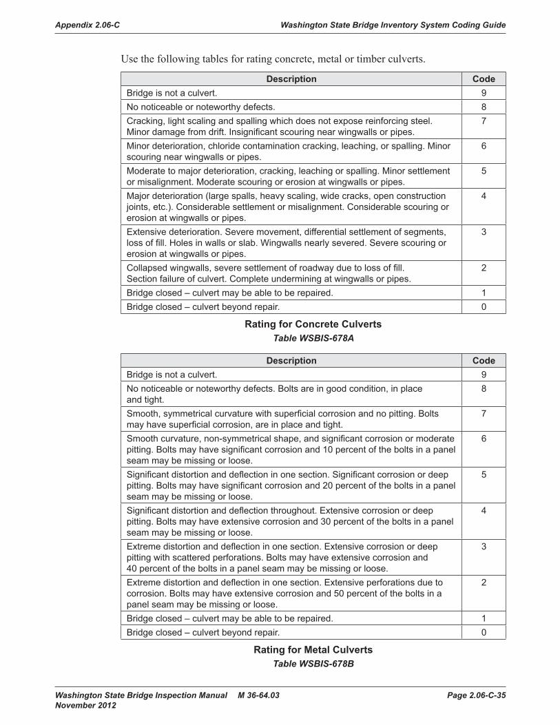
Appendix 2.06-C Washington State Bridge Inventory System Coding Guide
Washington State Bridge Inspection Manual M 36-64.03 Page 2.06-C-35 November 2012
Use the following tables for rating concrete, metal or timber culverts.
Description CodeBridge is not a culvert. 9No noticeable or noteworthy defects. 8Cracking, light scaling and spalling which does not expose reinforcing steel. Minor damage from drift. Insignificant scouring near wingwalls or pipes.
7
Minor deterioration, chloride contamination cracking, leaching, or spalling. Minor scouring near wingwalls or pipes.
6
Moderate to major deterioration, cracking, leaching or spalling. Minor settlement or misalignment. Moderate scouring or erosion at wingwalls or pipes.
5
Major deterioration (large spalls, heavy scaling, wide cracks, open construction joints, etc.). Considerable settlement or misalignment. Considerable scouring or erosion at wingwalls or pipes.
4
Extensive deterioration. Severe movement, differential settlement of segments, loss of fill. Holes in walls or slab. Wingwalls nearly severed. Severe scouring or erosion at wingwalls or pipes.
3
Collapsed wingwalls, severe settlement of roadway due to loss of fill. Section failure of culvert. Complete undermining at wingwalls or pipes.
2
Bridge closed – culvert may be able to be repaired. 1Bridge closed – culvert beyond repair. 0
Rating for Concrete CulvertsTable WSBIS-678A
Description CodeBridge is not a culvert. 9No noticeable or noteworthy defects. Bolts are in good condition, in place and tight.
8
Smooth, symmetrical curvature with superficial corrosion and no pitting. Bolts may have superficial corrosion, are in place and tight.
7
Smooth curvature, non-symmetrical shape, and significant corrosion or moderate pitting. Bolts may have significant corrosion and 10 percent of the bolts in a panel seam may be missing or loose.
6
Significant distortion and deflection in one section. Significant corrosion or deep pitting. Bolts may have significant corrosion and 20 percent of the bolts in a panel seam may be missing or loose.
5
Significant distortion and deflection throughout. Extensive corrosion or deep pitting. Bolts may have extensive corrosion and 30 percent of the bolts in a panel seam may be missing or loose.
4
Extreme distortion and deflection in one section. Extensive corrosion or deep pitting with scattered perforations. Bolts may have extensive corrosion and 40 percent of the bolts in a panel seam may be missing or loose.
3
Extreme distortion and deflection in one section. Extensive perforations due to corrosion. Bolts may have extensive corrosion and 50 percent of the bolts in a panel seam may be missing or loose.
2
Bridge closed – culvert may be able to be repaired. 1Bridge closed – culvert beyond repair. 0
Rating for Metal CulvertsTable WSBIS-678B

Washington State Bridge Inventory System Coding Guide Appendix 2.06-C
Page 2.06-C-36 Washington State Bridge Inspection Manual M 36-64.03 November 2012
Description CodeBridge is not a culvert. 9No noticeable or noteworthy defects. 8Insignificant deterioration, decay, or scour. No structural loss. 7Minor deterioration, decay, or scour. All primary structural elements are sound. 6Moderate deterioration, decay, or scour. All primary structural elements are sound but have some section loss.
5
Major deterioration, decay or scour. Advanced section loss or scour that affects the load capacity of the structure.
4
Extensive deterioration, decay, or scour. Advanced section loss or scour that significantly affects the load capacity of the structure.
3
Severe deterioration, decay, or scour. Critical structural members have obvious vertical or horizontal movement affecting structural stability.
2
Bridge closed – culvert may be able to be repaired. 1Bridge closed – culvert beyond repair. 0
Rating for Timber CulvertsTable WSBIS-678C
Null Status: Cannot be null.
Coding Requirements:Coded for Main Listing ‘on’ record: Yes, both for NBI and WSBISCoded for Main Listing ‘under’ record: Yes, for WSBIS onlyCoded for Secondary Listing ‘under’ record: No (data included with Main Listing ‘on’ record)Crossing record match: Identical for all crossing records
WSBIS Item 679 – Pier/Abutment Protection
FHWA Item 111 – Pier or Abutment Protection (for Navigation)
Table: tblInspectionReportsField Name: pier_abutment_protData Type: varchar
If WSBIS Item 386 - Navigation Control has been coded 1, use the codes below to indicate the presence and adequacy of pier or abutment protection features such as fenders, dolphins, etc. The condition of the protection devices may be a factor in the overall evaluation of WSBIS Item 676 - Substructure.

Appendix 2.06-C Washington State Bridge Inventory System Coding Guide
Washington State Bridge Inspection Manual M 36-64.03 Page 2.06-C-37 November 2012
WSDOT Code NBI Code Description1 1 Navigation protection not required2 2 In place and functioning3 3 In place but in a deteriorated condition4 4 In place but reevaluation of design suggested5 5 None present but reevaluation suggestedN [blank] Not applicable
Null Status: Cannot be null.
Coding Requirements:Coded for Main Listing ‘on’ record: Yes, both for NBI and WSBISCoded for Main Listing ‘under’ record: Yes, for WSBIS onlyCoded for Secondary Listing ‘under’ record: No (data included with Main Listing ‘on’ record)Crossing record match: Identical for all crossing records
NBI Commentary:WSDOT codes N where the NBI codes a blank. This field is translated in the NBI text file.
WSBIS Item 680 – Scour
FHWA Item 113 – Scour Critical Bridges
Table: tblInspectionReportsField Name: scour_codeData Type: varchar

Washington State Bridge Inventory System Coding Guide Appendix 2.06-C
Page 2.06-C-38 Washington State Bridge Inspection Manual M 36-64.03 November 2012
Code as indicated below to identify the current status of the bridge regarding its vulnerability to scour:
Code DescriptionN Bridge not over waterway.U Bridge with “unknown” foundation that has not been evaluated for scour. Until risk
can be determined, a plan of action should be developed and implemented to reduce the risk to users from a bridge failure during or immediately after a flood event (see HEC 23).
9 Bridge foundations (including piles) on dry land well above flood water elevations.8 Bridge foundations determined to be stable for the assessed or calculated scour
conditions. Scour is determined to be above top of footing (Example A) by:• assessment (e.g., bridge foundations are on rock formations that have been
determined to resist scour within the service life of the bridge), or• calculation, or• installation of properly designed countermeasures (see HEC 23).
7 Countermeasures have been installed to mitigate an existing problem with scour and to reduce the risk of bridge failure during a flood event. Instructions contained in a plan of action have been implemented to reduce the risk to users from a bridge failure during or immediately after a flood event.
5 Bridge foundations determined to be stable for assessed or calculated scour conditions. Scour is determined to be within the limits of footing or piles (Example B) by:• assessment (e.g., bridge foundations are on rock formations that have been
determined to resist scour within the service life of the bridge), or• calculations, or• installation of properly designed countermeasures (see HEC 23).
4 Bridge foundations determined to be stable for assessed or calculated scour conditions; field review indicates action is required to protect exposed foundations (see HEC 23).
3 Bridge is scour critical; bridge foundations determined to be unstable for assessed or calculated scour conditions:• Scour within limits of footing or piles (Example B)• Scour below spread-footing base or pile tips (Example C)
2 Bridge is scour critical; field review indicates that extensive scour has occurred at bridge foundations, which are determined to be unstable by: • a comparison of calculated scour and observed scour during the bridge
inspection, or• an engineering evaluation of the observed scour condition reported by the
bridge inspector in WSBIS Item 676 - Substructure.1 Bridge is scour critical; field review indicates that failure of piers/abutments is
imminent. Bridge is closed to traffic. Failure is imminent based on:• a comparison of calculated and observed scour during the bridge inspection, or• an engineering evaluation of the observed scour condition reported by the
bridge inspector in WSBIS Item 676 - Substructure.0 Bridge is scour critical. Bridge has failed and is closed to traffic.

Appendix 2.06-C Washington State Bridge Inventory System Coding Guide
Washington State Bridge Inspection Manual M 36-64.03 Page 2.06-C-39 November 2012
These codes are generally determined based on scour analyses made by hydraulic, geotechnical, or structural engineers. However, bridge inspectors play a key role in determining selected scour codes:
• Scour code 4 can be determined by the bridge inspector regardless of any previous higher scour code, based on observed conditions.
• For scour codes of 2 or less, the WSBIS Item 676 - Substructure code must have a matching code.
Example AAbove topof footing
CALCULATED SCOUR DEPTH ACTION NEEDED
Example BWithin limitsof footingor piles
Example CBelow pile tipsor spread-footing base
SPREAD FOOTING(NOT FOUNDED IN ROCK)
PILE FOOTING
None - scour code is 8
Conductfoundationstructuralanalysis - scour code is 5 or 3
Provide formonitoringand scour countermeasuresas necessary - scour code is 3
= Calculated scour depth
Figure WSBIS-680
Null Status: Cannot be null.
Coding Requirements:Coded for Main Listing ‘on’ record: Yes, both for NBI and WSBISCoded for Main Listing ‘under’ record: Yes, for WSBIS onlyCoded for Secondary Listing ‘under’ record: No (data included with Main Listing ‘on’ record)Crossing record match: Identical for all crossing records
NBI Commentary:The WSDOT description clarifies what scour codes are editable by inspectors and how they relate to the substructure condition code.

Washington State Bridge Inventory System Coding Guide Appendix 2.06-C
Page 2.06-C-40 Washington State Bridge Inspection Manual M 36-64.03 November 2012
This coding guide has eliminated codes T and 6, which are available in the NBI coding guide.
WSBIS Item W01 – Asphalt Depth (XX.XX inches)
Table: tblBridgesField Name: asphalt_depthData Type: numeric
Code the average depth of asphalt in inches on the deck as observed from field measurements, or as determined from comparing the design curb height against the measured curb height from the top of asphalt. Code zero when there is either no asphalt on the deck, or when the structure does not have a deck, including when asphalt pavement is placed on fill over a culvert.
Null Status: Null only when there is no on record associated with the bridge.
Coding Requirements:Coded for Main Listing ‘on’ record: Yes, for WSBIS onlyCoded for Main Listing ‘under’ record: NoCoded for Secondary Listing ‘under’ record: No (data included with Main Listing ‘on’ record)Crossing record match: Identical for all crossing records
WSBIS Item W02 – Design Curb Height (XX.XX inches)
Table: tblBridgesField Name: design_curb_heightData Type: numeric
Code the curb height shown on current bridge plans in inches. Code zero when there is no curb.
Null Status: Null only when there is no on record associated with the bridge.
Coding Requirements:Coded for Main Listing ‘on’ record: Yes, for WSBIS onlyCoded for Main Listing ‘under’ record: NoCoded for Secondary Listing ‘under’ record: No (data included with Main Listing ‘on’ record)Crossing record match: Identical for all crossing records
WSBIS Item W03 – Speed Limit (XX MPH)
Table: tblCrossingField Name: speed_limitData Type: integer
Code the posted speed limit for the inventory route at the bridge site. In cases where the speed limit changes in the immediate vicinity of the bridge, code the higher speed limit. In cases where the speed limit is not known, use engineering judgement and the following guidelines:

Appendix 2.06-C Washington State Bridge Inventory System Coding Guide
Washington State Bridge Inspection Manual M 36-64.03 Page 2.06-C-41 November 2012
Urban Freeways: 60 mphRural Freeways: 70 mphState Highways: 60 mphUrban Arterials: 45 mphCity/Town Streets: 35 mphAlleys/Access Roads: 20 mph
Null Status: Null only when there is no on record associated with the bridge.
Coding Requirements:Coded for Main Listing ‘on’ record: Yes, for WSBIS onlyCoded for Main Listing ‘under’ record: NoCoded for Secondary Listing ‘under’ record: No (data included with Main Listing ‘on’ record)Crossing record match: Identical for all crossing records
WSBIS Items 684, 685, 686, 687 – Traffic Safety
FHWA 36 – Traffic Safety Features
Bridge inspection shall include the recording of information on traffic safety features so that the evaluation of their adequacy can be made.
Use the following codes for each of the four traffic safety segments:
Code Description0 Inspected feature does not meet currently acceptable standards or a safety
feature is required and none is provided.1 Inspected feature meets currently acceptable standards.N Not applicable or a safety feature is not required.
Null Status: Cannot be null if bridge has an on record, must be null if the bridge does not have an on record.
Coding Requirements:Coded for Main Listing ‘on’ record: Yes, both for NBI and WSBISCoded for Main Listing ‘under’ record: NoCoded for Secondary Listing ‘under’ record: No (data included with Main Listing ‘on’ record)Crossing record match: Identical for all crossing records
NBI Commentary:WSDOT has applied state safety standards to determine how these fields are coded.
Washington State Bridge Inventory System Coding Guide Appendix 2.06-C
Page 2.06-C-42 Washington State Bridge Inspection Manual M 36-64.03 November 2012
WSBIS Item 684 – Bridge Rails
FHWA 36A – Traffic Safety Features, Bridge Railings
Table: tblInspectionReportsField Name: bridge_rail_adqcyData Type: varchar
Bridge railings should be coded to reflect the current WSDOT standards. Acceptable crash tested bridge rails fall into two general categories.
Thrie-beam Retrofit
• Thrie-beam mounted to baluster rail
• Steel truss and Thrie-beam
• Edge mounted Thrie-beam
• Thrie-beam mounted to steel posts on concrete deck
• Thrie-beam mounted to open girder
Concrete Rail
• New Jersey style rail
• F-shaped concrete rail
• Single slope concrete rail
• 32” vertical concrete parapet
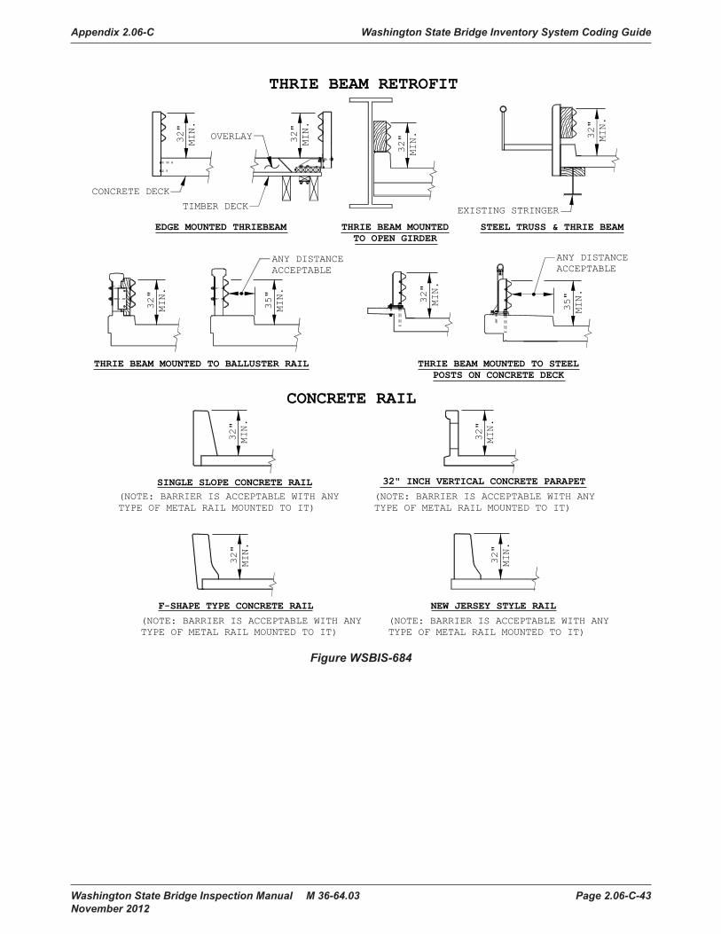
Appendix 2.06-C Washington State Bridge Inventory System Coding Guide
Washington State Bridge Inspection Manual M 36-64.03 Page 2.06-C-43 November 2012
SINGLE SLOPE CONCRETE RAIL(NOTE: BARRIER IS ACCEPTABLE WITH ANYTYPE OF METAL RAIL MOUNTED TO IT)
32"
MIN.
F-SHAPE TYPE CONCRETE RAIL
(NOTE: BARRIER IS ACCEPTABLE WITH ANYTYPE OF METAL RAIL MOUNTED TO IT)
32"
MIN.
CONCRETE RAIL
THRIE BEAM RETROFIT
NEW JERSEY STYLE RAIL
(NOTE: BARRIER IS ACCEPTABLE WITH ANYTYPE OF METAL RAIL MOUNTED TO IT)
32"
MIN.
THRIE BEAM MOUNTED TO BALLUSTER RAIL
THRIE BEAM MOUNTEDTO OPEN GIRDER
32"
MIN.
ANY DISTANCEACCEPTABLE
EXISTING STRINGER
THRIE BEAM MOUNTED TO STEELPOSTS ON CONCRETE DECK
35"
MIN.
32"
MIN.
OVERLAY
EDGE MOUNTED THRIEBEAM
35"
MIN.
ANY DISTANCEACCEPTABLE
CONCRETE DECK32"
MIN.
TIMBER DECK
32"
MIN.
STEEL TRUSS & THRIE BEAM
32"
MIN.
32" INCH VERTICAL CONCRETE PARAPET
(NOTE: BARRIER IS ACCEPTABLE WITH ANYTYPE OF METAL RAIL MOUNTED TO IT)
32"
MIN.
32"
MIN.
Figure WSBIS-684

Washington State Bridge Inventory System Coding Guide Appendix 2.06-C
Page 2.06-C-44 Washington State Bridge Inspection Manual M 36-64.03 November 2012
WSBIS Item 685 – Transitions
FHWA 36B – Traffic Safety Features, Transitions
Table: tblInspectionReportsField Name: rail_trans_adqcyData Type: varchar
Transition details are shown in WSDOT Standard Plans C-3 thru C-3c. Features that the inspector should note are:
• If guardrails are not required, the absence of transitions is automatically acceptable and coded as “1”.
• Transitions must be nested (two layers). In most cases this will be Thrie-beam. W-beam is allowed only when there is insufficient bridge rail height to accommodate the Thrie-beam transition.
• Post spacing should decrease in the transition resulting in gradual stiffening as a vehicle moves along the transition from a flexible guardrail to the more rigid concrete bridge rail.
• Type III transitions (hollow steel post) have generally been retrofitted, but are only acceptable if they have been retrofitted with a wooden block out. On one-way highways, the non-retrofitted posts are acceptable on the trailing edge. Unless further investigation shows that it meets current standards, this is the criteria for acceptance that will be used.

Appendix 2.06-C Washington State Bridge Inventory System Coding Guide
Washington State Bridge Inspection Manual M 36-64.03 Page 2.06-C-45 November 2012
BridgeRail
Transition Approach Guardrail Guardrailterminal
Note:See Standard PLans Section Cfor current Standards
Notes:A. Approach guardrail required at all corners for reversible lane bridges.
B. Approach guardrail may not be required if the bridge is in an urban area with sidewalks containing well beyond the Bridge ends.
2 way roadway5 lanes or more
2 way roadway4 lanes or less
Divided highways
Approach guardrail requiredwhere shown (Typ.)
Bridge end Curb face extension line
Figure WSBIS-685
WSBIS Item 686 – Guardrails
FHWA 36C – Traffic Safety Features, Approach Guardrail
Table: tblInspectionReportsField Name: aprch_rail_adqcyData Type: varchar
W-beam and Thrie-beam are acceptable rail types. Details of these rails are shown in Standard Plans C-1 thru C-1c. Features that the inspector should pay close attention to while inspecting the approach rail are:
• Rails are not necessarily required at all four corners of the bridge. Code Guardrails as “1” when not required.
• Posts should be 6″ x 8″ timber (nominal), or W6x9’s, spaced at 6′ 3″ o.c. Nested Thrie-beam is also acceptable but requires lower post spacing.
• Guardrail height (from ground to top of W-beam) should be between 26″ and 28″.
• Guardrail height (from ground to top of Thrie-beam) should be 30″.
• Concrete rail is acceptable.

Washington State Bridge Inventory System Coding Guide Appendix 2.06-C
Page 2.06-C-46 Washington State Bridge Inspection Manual M 36-64.03 November 2012
WSBIS Item 687 – Terminals
FHWA 36D – Traffic Safety Features, Approach Guardrail Ends
Table: tblInspectionReportsField Name: rail_end_adqcyData Type: varchar
• Terminals are to be coded as “1” or “0” if they are within a reasonable distance of the bridge. On a fill embankment, this would be near the bottom of the fill slope (Design Manual, Figure 700-5). Otherwise they will be coded as an “N”.
• If guardrails are not required, the absence of terminals is automatically acceptable and coded as “1”.
• Acceptable guardrail terminals are shown in the Washington State Standard Plans or Design Manual and are as follows:
1. Buried terminals Standard Plans C-4 and C-4a.
2. Bent back, slotted terminals with anchor cables Figure 710-13.
3. Square terminals with end piece designed to turn over when impacted Figure 710-13.
4. Attenuator style terminals (don’t need to be slotted) Sec 720.
5. Inertial barriers (barrels filled with sand) Sec 720.
6. Median bull nose terminals Figure C-2C.
WSBIS Item 688 – Revise Rating Flag
Table: tblInspectionReportsField Name: rating_calc_flagData Type: varchar
This code indicates whether or not the bridge should be reviewed for a revised rating based on field conditions.
Y Yes, review rating * Null field, does not apply
See Chapter 5, Section 5.02.
Null Status: Null when rating review is not required.
Coding Requirements:Coded for Main Listing ‘on’ record: Yes, for WSBIS onlyCoded for Main Listing ‘under’ record: NoCoded for Secondary Listing ‘under’ record: No (data included with Main Listing ‘on’ record)Crossing record match: Identical for all crossing records

Appendix 2.06-C Washington State Bridge Inventory System Coding Guide
Washington State Bridge Inspection Manual M 36-64.03 Page 2.06-C-47 November 2012
WSBIS Item 693 – Soundings Flag
Table: tblInspectionReportsField Name: inspn_soundings_flagData Type: varchar
This code indicates whether or not soundings of the streambed (streambed cross sections at the bridge) are required.
Y Soundings need to be taken. * Null field, does not apply
This field is coded as part of the inspection planning process, and instructs the inspector to take soundings. When soundings are taken, the flag should be changed to null.
Note that pedestrian bridges over waterways are managed for soundings and may be coded Y as appropriate.
Null Status: Null when soundings are not required.
Coding Requirements:Coded for Main Listing ‘on’ record: Yes, for WSBIS onlyCoded for Main Listing ‘under’ record: Yes, for WSBIS onlyCoded for Secondary Listing ‘under’ record: No (data included with Main Listing ‘on’ record)Crossing record match: Identical for all crossing records
WSBIS Item 694 – Clearance Flag
Table: tblInspectionReportsField Name: measure_clrnc_flagData Type: varchar
This field identifies which clearances need to be checked on a bridge.
C Measure horizontal/lateral and vertical clearances. H Measure horizontal/lateral clearances. V Measure vertical clearances. * Null field, does not apply
This field is coded as part of the inspection planning process, and instructs the inspector to take, document and code clearance measurements. Unless otherwise instructed, vertical and horizontal clearances on the bridge are to be verified, and vertical, horizontal and lateral clearances under the bridge are to be verified. When measurements are taken, documented and coded, this field should be made null.
Null Status: Null when measurements are not required.
Coding Requirements:Coded for Main Listing ‘on’ record: Yes, for WSBIS onlyCoded for Main Listing ‘under’ record: Yes, for WSBIS onlyCoded for Secondary Listing ‘under’ record: No (data included with Main Listing ‘on’ record)Crossing record match: Identical for all crossing records

Washington State Bridge Inventory System Coding Guide Appendix 2.06-C
Page 2.06-C-48 Washington State Bridge Inspection Manual M 36-64.03 November 2012
WSBIS Item W04 – Subject to NBIS Flag
Table: tblBridgesField Name: nbi_bridgeData Type: varchar
This field identifies whether or not the bridge is subject to the National Bridge Inspection Standards (NBIS).
Y Bridge is subject to the NBIS N Bridge is not subject to the NBIS.
This field is based on 23 CFR 650.305 and the Questions and Answers paragraphs Q303-1 through Q303-6. For reference, see www.fhwa.dot.gov/bridge/nbis.htm.
Structures subject to the NBIS include all publicly owned highway structures carrying public roads over a depression or obstruction and having an opening measured along the center of the roadway of more than 20 feet between one of the following:
• Undercopings of abutments
• Spring lines of arches
• Extreme ends of openings for multiple box culverts
• Extreme ends of openings for multiple pipe culverts where the clear distance between pipes is less than half of the smaller contiguous pipe
Structures not subject to the NBIS include:
• Sign support structures
• High mast lighting
• Retaining walls
• Noise barrier structures
• Overhead traffic signs
• Tunnels
• Structures carrying only pedestrians
• Structures carrying only railroad
Ownership and access are also important factors. To be subject to the NBIS, a structure must be both publicly owned and publicly accessible. Structures not subject to the NBIS include:
• Privately owned structures accessible to the public (e.g., road association structures)
• Publicly owned bridges that are not accessible to the public (e.g., structures behind gates used to access dams for agency employees and contractors)
Null Status: Cannot be null.

Appendix 2.06-C Washington State Bridge Inventory System Coding Guide
Washington State Bridge Inspection Manual M 36-64.03 Page 2.06-C-49 November 2012
Coding Requirements:Coded for Main Listing ‘on’ record: Yes, for WSBIS onlyCoded for Main Listing ‘under’ record: Yes, for WSBIS onlyCoded for Secondary Listing ‘under’ record: No (data included with Main Listing ‘on’ record)Crossing record match: Identical for all crossing records
WSBIS Item W05 – Bridge Account Manager (BAM)
Table: tblBATSField Name: work_order Data Type: varcharField Name: cost_category Data Type: varcharField Name: weekend_rate Data Type: varcharField Name: per_diem Data Type: varchar
BAM codes are used to track and categorize inspection costs.
Work Order This field identifies the bridge owner responsible for inspection costs:
0 WSDOT and GA owned bridges (WSBIS Item 019 codes 01 and 21)1 Local Agency bridges (WSBIS Item 019 codes 02, 04, 12, 13, 24, 25)2 State Ferry bridges (WSBIS Item 019 code of 22)3 State Parks (WSBIS Item 019 code of 11)9 No charges (includes Underwater inspections)
Cost Category This field identifies the staffing and equipment used for inspections:
0 All inspections performed by a lead inspector and a co-inspector team from BPO(2 man routine). This category includes inspections that use bucket trucks, man lifts, and attenuators or traffic control provided by region maintenance.
1 All inspections performed by a lead inspector, co-inspector, and equipment operator team from BPO (3 man UBIT). Generally the equipment will be a UBIT, but this category includes any other equipment that involves a BPO equipment operator.
2 All inspections performed by a co-inspector and equipment operator team from BPO (2 man UBIT). Generally these inspections will be done for local agencies who provide their own lead inspector.
3 All underwater inspections performed by the BPO dive team.
Weekend This field identifies the overtime status of the inspection:
0 Inspection performed on weekday(s) Monday–Thursday1 Inspection performed on weekend(s) Friday–Sunday
Any inspection performed on both weekdays and weekends shall be considered weekend work.

Washington State Bridge Inventory System Coding Guide Appendix 2.06-C
Page 2.06-C-50 Washington State Bridge Inspection Manual M 36-64.03 November 2012
Per Diem This field identifies the State lodging rate applied to the inspection:
0 No overnight stay associated with inspection.1 Minimum lodging rate associated with inspection.2 Other than minimum lodging rate associated with inspection.
Lodging rates are available at www.ofm.wa.gov/resources/travel/colormap.pdf.
Note that rates are determined by the location of the hotel. Lodging rates are associated with all bridges inspected while on travel status when at least one inspector is staying in a hotel that evening or stayed in a hotel the previous evening. Lodging rates are applied based on where the hotel is located at the end of the day. On the last day of a multi-day inspection trip, the lodging rate is based on the previous night’s location.
Null Status: Cannot be null when an inspection has been performed. Will be null for Informational and Inventory report types.
Coding Requirements:Coded for Main Listing ‘on’ record: Yes, for WSBIS onlyCoded for Main Listing ‘under’ record: Yes, for WSBIS onlyCoded for Secondary Listing ‘under’ record: No (data included with Main Listing ‘on’ record)Crossing record match: Identical for all crossing records

Appendix 2.06-C Washington State Bridge Inventory System Coding Guide
Washington State Bridge Inspection Manual M 36-64.03 Page 2.06-C-51 November 2012
WSBIS Item 001 – Structure Identifier
FHWA Item 8 – Structure Number
Table: tblBridgesField Name: structure_idData Type: varchar
This field must be unique for every structure in the Washington State Bridge Inventory, and cannot change for the life of the structure. Furthermore, when a new bridge replaces an old bridge, a new unique structure identifier must be coded. The old identifier cannot be “recycled.”
The WSDOT Inventory Engineer at the Bridge Preservation Office assigns the structure identifier when the original bridge inventory record is processed. When initially creating a new structure in BridgeWorks, a temporary structure ID is generated with an X as the first character, and the remainder generated based on the inspector certification number and a serial number. This temporary structure ID will be changed when the record is “released” into the database.
Null Status: Cannot be null
Coding Requirements:Coded for Main Listing ‘on’ record: Yes, both for NBI and WSBISCoded for Main Listing ‘under’ record: Yes, both for NBI and WSBISCoded for Secondary Listing ‘under’ record: No (data included with Main Listing ‘on’ record)Crossing record match: Identical for all crossing records
NBI Commentary:This field is translated to the NBI by adding 7 zeroes to the end of the 8-digit WSBIS code. This translation is done automatically with the generation of the NBI text file. The NBI coding guide states that all structures with a closed median should be considered one structure, not two, presumably in cases when they are actually structurally distinct. In some instances WSDOT has coded these structures separately.
WSBIS Item 009 – Bridge Number
Table: tblBridgesField Name: bridge_noData Type: varchar
This is a unique (to the owner agency) alphanumeric code assigned by the owner of the bridge. This field does not require all spaces to be filled; however, the field cannot be left blank.
WSDOT owned structure bridge numbers are formatted as follows:[route number] / [alphanumeric character string]

Washington State Bridge Inventory System Coding Guide Appendix 2.06-C
Page 2.06-C-52 Washington State Bridge Inspection Manual M 36-64.03 November 2012
WSDOT bridge numbers follow several rules:
1. The / character is always in the 4th position, with leading blanks as needed. For example, bridges on I-5 are coded with two leading blanks followed by a 5 and a slash. Bridges on US 395 have no leading blanks.
2. In general, every bridge must have a unique bridge number. The exception is when bridges are replaced the bridge number usually doesn’t change. In this case, the obsoleted bridge will have the same bridge number.
3. The alphanumeric character string following the slash is numerically sequenced by increasing route milepoint, and is often followed by letter characters:
E east bridge of a pair on a divided south-north routeW west bridge of a pair on a divided south-north routeN north bridge of a pair on a divided west-east routeS south bridge of a pair on a divided west-east routeE-N ramp carrying from eastbound to northbound (vary as needed)ECD eastbound collector distributor (vary as needed)C culvertP pedestrian bridgeDV detention vaultA bridge not on mainlineF bridge on frontage roadALT bridge on alternate route mainlineSP bridge on spur route
Null Status: Cannot be null.
Coding Requirements:Coded for Main Listing ‘on’ record: Yes, for WSBIS onlyCoded for Main Listing ‘under’ record: Yes, for WSBIS onlyCoded for Secondary Listing ‘under’ record: No (data included with Main Listing ‘on’ record)Crossing record match: Identical for all crossing records
Examples:90/43S Eastbound I-90 bridge at Mercer Slough in South Bellevue395/101N-E Ramp carrying northbound US395 traffic to eastbound Lewis St.5/313P Pedestrian bridge over I-5 in Tumwater

Appendix 2.06-C Washington State Bridge Inventory System Coding Guide
Washington State Bridge Inspection Manual M 36-64.03 Page 2.06-C-53 November 2012
WSBIS Item W06 – Program Manager
Table:tbl6ControEntityField Name: program_manager_gidData Type: uniqueidentifier
This field identifies the individual responsible for bridge inspection and reporting as described in the National Bridge Inspection Standards Title 23 CFR 650.307. Both the NBI program manager and delegated program managers are listed in this field as appropriate.
In cases when the bridge is not subject to the NBIS, this field identifies who is responsible for inspecting the bridge and maintaining the bridge records in accordance with WSDOT policies.
Null Status: Cannot be null.
Coding Requirements:Coded for Main Listing ‘on’ record: Yes, for WSBIS onlyCoded for Main Listing ‘under’ record: Yes, for WSBIS onlyCoded for Secondary Listing ‘under’ record: No (data included with Main Listing ‘on’ record)Crossing record match: Identical for all crossing records
WSBIS Item 019 – Owner
FHWA Item 22 – Owner
Table: tblBridgesField Name: agency_idData Type: integer
The actual name of the owner of the bridge shall be recorded on the inspection form. The code shall be used to represent the type of agency that is the primary owner of the structure. If more than one agency has equal ownership, code one agency in the hierarchy of State, Federal, county, city, railroad, and other private.

Washington State Bridge Inventory System Coding Guide Appendix 2.06-C
Page 2.06-C-54 Washington State Bridge Inspection Manual M 36-64.03 November 2012
WSDOT Code NBI Code Description1 001 State Highway Agency2 002 County Highway Agency4 004 City or Municipal Highway Agency11 011 State Park, Forest, or Reservation Agency12 012 County Park, Forest, or Reservation Agency13 012 City Park, Forest, or Reservation Agency21 021 Other State Agencies22 001 Washington State Ferries24 025 Other County Agency25 025 Other City or Local Agencies26 026 Private (other than railroad)27 027 Railroad31 031 State Toll Authority32 032 County Toll Authority33 032 City or Other Toll Authority60 060 Other Federal Agencies (not listed below)61 061 Indian Tribal Government62 062 Bureau of Indian Affairs63 063 Bureau of Fish and Wildlife64 064 U.S. Forest Service66 066 National Park Service68 068 Bureau of Land Management69 069 Bureau of Reclamation70 070 Corps of Engineers (Civil)71 071 Corps of Engineers (Military)72 072 Air Force73 073 Navy/Marines74 074 Army80 080 Unknown92 001 Idaho maintenance responsibility93 001 Oregon maintenance responsibility

Appendix 2.06-C Washington State Bridge Inventory System Coding Guide
Washington State Bridge Inspection Manual M 36-64.03 Page 2.06-C-55 November 2012
Null Status: Cannot be null
Coding Requirements:Coded for Main Listing ‘on’ record: Yes, both for NBI and WSBISCoded for Main Listing ‘under’ record: Yes, for WSBIS onlyCoded for Secondary Listing ‘under’ record: No (data included with Main Listing ‘on’ record)Crossing record match: Identical for all crossing records
NBI Commentary:Selected codes have been eliminated because they are not used by any bridges in Washington State (NSA, Pentagon, etc.). Selected codes were added, generally to differentiate county agencies from other local agencies, provide a unique code for Washington State Ferries, and codes for Oregon and Idaho border bridges maintained by these other state agencies.
WSBIS Item 021 – County Code
FHWA Item 3 – County Code
Table: tblBridgesField Name: county_idData Type: integer
This code identifies the county in which the bridge is located. If this is a jointly owned bridge, the county that is responsible for reporting the data to the inventory should be entered here.

Washington State Bridge Inventory System Coding Guide Appendix 2.06-C
Page 2.06-C-56 Washington State Bridge Inspection Manual M 36-64.03 November 2012
County Name WSBIS Code NBI CodeAdams 1 001Asotin 2 003Benton 3 005Chelan 4 007Clallam 5 009Clark 6 011Columbia 7 013Cowlitz 8 015Douglas 9 017Ferry 10 019Franklin 11 021Garfield 12 023Grant 13 025Grays Harbor 14 027Island 15 029Jefferson 16 031King 17 033Kitsap 18 035Kittitas 19 037Klickitat 20 039Lewis 21 041Lincoln 22 043Mason 23 045Okanogan 24 047Pacific 25 049Pend Oreille 26 051Pierce 27 053San Juan 28 055Skagit 29 057Skamania 30 059Snohomish 31 061Spokane 32 063Stevens 33 065Thurston 34 067Wahkiakum 35 069Walla Walla 36 071Whatcom 37 073Whitman 38 075Yakima 39 077
Appendix 2.06-C Washington State Bridge Inventory System Coding Guide
Washington State Bridge Inspection Manual M 36-64.03 Page 2.06-C-57 November 2012
Null Status: Cannot be null
Coding Requirements:Coded for Main Listing ‘on’ record: Yes, both for NBI and WSBISCoded for Main Listing ‘under’ record: Yes, both for NBI and WSBISCoded for Secondary Listing ‘under’ record: No (data included with Main Listing ‘on’ record)Crossing record match: Identical for all crossing records
NBI Commentary:The WSBIS county code is translated to the NBI county code using the formula (WSBIS Code x 2) – 1 = NBI code and as shown above.
WSBIS Item 023 – City
Table: tblBridgesField Name: city_idData Type: integer
This is the 1990 federal census place code, updated by OFM for cities incorporated after 1999. These codes are available in an Excel spreadsheet within the “County and city codes” tab at www.ofm.wa.gov/pop/annex/default.asp.
Use the 4-digit Place_1990 column in the City Codes spreadsheet tab.
If the bridge is not in a city, code zeroes.
Examples:Aberdeen = 0005Zillah = 1500
Null Status: Cannot be null.
Coding Requirements:Coded for Main Listing ‘on’ record: Yes, for WSBIS onlyCoded for Main Listing ‘under’ record: Yes, for WSBIS onlyCoded for Secondary Listing ‘under’ record: No (data included with Main Listing ‘on’ record)Crossing record match: Identical for all crossing records
WSBIS Item 132 – Bridge Name
Table: tblBridgesField Name: bridge_nameData Type: varchar
This is the name of the bridge, either as determined by legislative action or as determined by the bridge owner. If the bridge name is more than one word, separate words with a blank space. If the name of the bridge is too long to fit in the field, use abbreviations to shorten it. Left-justify the entry and leave following columns blank.

Washington State Bridge Inventory System Coding Guide Appendix 2.06-C
Page 2.06-C-58 Washington State Bridge Inspection Manual M 36-64.03 November 2012
Null Status: Cannot be null.
Coding Requirements:Coded for Main Listing ‘on’ record: Yes, for WSBIS onlyCoded for Main Listing ‘under’ record: Yes, for WSBIS onlyCoded for Secondary Listing ‘under’ record: No (data included with Main Listing ‘on’ record)Crossing record match: Identical for all crossing records
WSBIS Item 156 – Location
FHWA Item 9 – Location
Table: tblCrossingField Name: locationData Type: varchar
This item contains a narrative description of the bridge location for the inventory route. Descriptions should be oriented ahead on station whenever possible. Do not use city limits, as these boundaries may move. This item shall be left justified.
Examples:19.3 E JCT SR 20314.7 E MASON CO
This item is used to code the location for all Main Listings. Secondary Listings are coded on the WB74 tab, and are visible in BridgeWorks Inventory Management mode.
Null Status: Cannot be null
Coding Requirements:Coded for Main Listing ‘on’ record: Yes, both for NBI and WSBISCoded for Main Listing ‘under’ record: Yes, both for NBI and WSBISCoded for Secondary Listing ‘under’ record: Yes, both for NBI and WSBIS (see WSBIS Item 156 on the WB74 tab)Crossing record match: Varies as needed for crossing records
WSBIS Items 181, 183, and 185 – Section, Township, and Range
Table: tblBridgesField Name: section Data Type: varcharField Name: township Data Type: varcharField Name: range Data Type: varchar
Section, township, and range numbers are location markers established by survey mapping. If the bridge runs along a section, township, or range line, use the smaller of the two numbers. If a bridge crosses any line, use the number at the beginning of the bridge.

Appendix 2.06-C Washington State Bridge Inventory System Coding Guide
Washington State Bridge Inspection Manual M 36-64.03 Page 2.06-C-59 November 2012
WSBIS Item 181 – Section This is the number of the section in which the bridge is located. Enter a numeric code from ‘01’ to ‘36’.
WSBIS Item 183 – Township This is the number of the township in which the bridge is located. Enter a numeric code from ‘01’ to ‘41’. Township designations carry a directional suffix (north or south); however, since all townships in Washington are north, this directional indicator need not be entered.
WSBIS Item 185 – Range This is the number of the range in which this bridge is located. There are two parts to this field. In the first two columns, enter the number of the range in which the bridge is located. Valid ranges are:
01 through 47 if the third column is E01 through 16 If the third column is W.
In the third column, enter the directional suffix which indicates the position of the range in relation to the Willamette Meridian. Enter one of the following codes:
E EastW West
A map of section, township and range information is available at www.wsdot.wa.gov/data/tools/geoportal/.
Null Status: Cannot be null.
Coding Requirements:Coded for Main Listing ‘on’ record: Yes, for WSBIS onlyCoded for Main Listing ‘under’ record: Yes, for WSBIS onlyCoded for Secondary Listing ‘under’ record: No (data included with Main Listing ‘on’ record)Crossing record match: Identical for all crossing records
WSBIS Item 188 – Latitude (XX degrees XX minutes XX.XX seconds)
FHWA Item 16 – Latitude
Table: tblBridges Field Name: latitude Data Type: Computed, realTable: tblBridges Field Name: latitude_degree Data Type: NumericTable: tblBridges Field Name: latitude_minute Data Type: numericTable: tblBridges Field Name: latitude_second Data Type: numeric
Code the latitude in degrees, minutes and seconds to the nearest hundredth of a second using the NAD 83/91 - North American Datum of 1983, with 91 adjustments. For on records, the latitude should be taken at the beginning of the bridge at the centerline of the roadway if traffic allows, at the shoulder as necessary. For ‘under’ records, the latitude should be taken at the centerline of the inventory route where it crosses under the bridge. Generally this can be most easily taken from the deck of the bridge crossing over the route.

Washington State Bridge Inventory System Coding Guide Appendix 2.06-C
Page 2.06-C-60 Washington State Bridge Inspection Manual M 36-64.03 November 2012
Null Status: Cannot be null
Coding Requirements:Coded for Main Listing ‘on’ record: Yes, both for NBI and WSBISCoded for Main Listing ‘under’ record: Yes, both for NBI and WSBISCoded for Secondary Listing ‘under’ record: No (data included with Main Listing ‘on’ record)Crossing record match: Identical for all crossing records
WSBIS Item 196 – Longitude (XXX degrees XX minutes XX.XX seconds) 9 digits
FHWA Item 17 – Longitude
Table: tblBridges Field Name: longitude Data Type: Computed, realTable: tblBridges Field Name: longitude_degree Data Type: NumericTable: tblBridges Field Name: longitude_minute Data Type: numericTable: tblBridges Field Name: longitude_second Data Type: numeric
Code the longitude in degrees, minutes and seconds to the nearest hundredth of a second using the NAD 83/91 - North American Datum of 1983, with 91 adjustments. Note that GPS devices will show a negative number, but this field must be coded as a positive number. For on records, the longitude should be taken at the beginning of the bridge at the centerline of the roadway if traffic allows, at the shoulder as necessary. For ‘under’ records, the longitude should be taken at the centerline of the inventory route where it crosses under the bridge. Generally this can be most easily taken from the deck of the bridge crossing over the route.
Null Status: Cannot be null
Coding Requirements:Coded for Main Listing ‘on’ record: Yes, both for NBI and WSBISCoded for Main Listing ‘under’ record: Yes, both for NBI and WSBISCoded for Secondary Listing ‘under’ record: No (data included with Main Listing ‘on’ record)Crossing record match: Identical for all crossing records

Appendix 2.06-C Washington State Bridge Inventory System Coding Guide
Washington State Bridge Inspection Manual M 36-64.03 Page 2.06-C-61 November 2012
WSBIS Item 232 – Features Intersected
FHWA Item 6 – Features Intersected
Table: tblBridgesField Name: feature_intersectedData Type: varchar
This item contains a description of the features intersected by the structure. The data in this segment shall be left justified and is limited to 24 characters.
Examples:SR 99, BLUE R, RR (see figure below)I-405 N-E & N-W RAMPSGOOSE CREEKSR 524 SPUR/44TH AVE W
Simpson Road N.W.
SR 99
(Aurora Ave)Union
PacificRailroad
Blue River
Figure WSBIS-232
Null Status: Cannot be null
Coding Requirements:Coded for Main Listing ‘on’ record: Yes, both for NBI and WSBISCoded for Main Listing ‘under’ record: Yes, both for NBI and WSBISCoded for Secondary Listing ‘under’ record: No (data included with Main Listing ‘on’ record)Crossing record match: Identical for all crossing records
NBI Commentary:The NBI coding guide separates this field into two segments (6A with 24 characters and 6B with 1 character). However, it’s also stated that 6B is not used. The WSBIS coding guide eliminates any reference to 6B, but a blank space is created automatically in the NBI text file. In addition, the NBI coding guide specifies the use of parentheses which is ignored.

Washington State Bridge Inventory System Coding Guide Appendix 2.06-C
Page 2.06-C-62 Washington State Bridge Inspection Manual M 36-64.03 November 2012
WSBIS Item 256 – Facilities Carried
FHWA Item 7 – Facility Carried by Structure
Table: tblBridgesField Name: facilities_carriedData Type: varchar
The facility being carried by the structure shall be recorded and coded. In all situations this item describes the use on the structure. This item shall be left justified and is limited to 18 characters.
Examples:US 12MAIN STREETISRAEL RDRAILROADPEDESTRIANS
Null Status: Cannot be null
Coding Requirements:Coded for Main Listing ‘on’ record: Yes, both for NBI and WSBISCoded for Main Listing ‘under’ record: Yes, both for NBI and WSBISCoded for Secondary Listing ‘under’ record: No (data included with Main Listing ‘on’ record)Crossing record match: Identical for all crossing records
WSBIS Item 274 – Region Code
FHWA Item 2 – Highway Agency District
Table: tblBridgesField Name: region_codeData Type: varchar
This is the WSDOT region in which the bridge is located.
WSDOT Code NBI Code Region NameNW 01 Northwest RegionNC 02 North Central RegionOL 03 Olympic RegionSW 04 Southwest RegionSC 05 South Central RegionEA 06 Eastern Region
A region boundary map can be found at www.wsdot.wa.gov/mapsdata/products/digitalmapsdata.htm.

Appendix 2.06-C Washington State Bridge Inventory System Coding Guide
Washington State Bridge Inspection Manual M 36-64.03 Page 2.06-C-63 November 2012
Null Status: Cannot be null
Coding Requirements:Coded for Main Listing ‘on’ record: Yes, both for NBI and WSBISCoded for Main Listing ‘under’ record: Yes, for WSBIS onlyCoded for Secondary Listing ‘under’ record: No (data included with Main Listing ‘on’ record)Crossing record match: Identical for all crossing records
NBI Commentary:As required, this code is translated to a 2-digit numeric code as shown above.
WSBIS Item 276 – Federal Information Processing Standards (FIPS) Code
FHWA Item 4 – Place Code
Table: tblBridgesField Name: fips_codeData Type: varchar
Code all zeroes for this field.
Null Status: Cannot be null
Coding Requirements:Coded for Main Listing ‘on’ record: Yes, both for NBI and WSBISCoded for Main Listing ‘under’ record: Yes, both for NBI and WSBISCoded for Secondary Listing ‘under’ record: No (data included with Main Listing ‘on’ record)Crossing record match: Identical for all crossing records
NBI Commentary:Federal Information Processing Standards were withdrawn by the National Institute of Standards and Technology on January 1, 2006, with the intent to replace them with the Geographic Names Information System (GNIS). On this basis, WSDOT has chosen not to maintain FIPS codes. See the following links for more information: http://geonames.usgs.gov/docs/fips55_change.pdf http://nhd.usgs.gov/gnis.html

Washington State Bridge Inventory System Coding Guide Appendix 2.06-C
Page 2.06-C-64 Washington State Bridge Inspection Manual M 36-64.03 November 2012
WSBIS Item 285 – Toll
FHWA Item 20 – Toll
Table: tblBridgesField Name: toll_codeData Type: varchar
The toll status of the structure is indicated by this item. Interstate toll segments under Secretarial Agreement (Title 23 - United States Code - Highways Section 129 as amended by 1991 ISTEA and prior legislation) shall be identified separately. Use one of the following codes:
Code Description1 Toll bridge. Tolls are paid specifically to use the structure.2 On toll road. The structure carries a toll road, that is, tolls are paid to use the
facility, which includes both the highway and the structure.3 On free road. The structure is tollfree and carries a tollfree highway.4 On Interstate toll segment under Secretarial Agreement. Structure functions
as a part of the toll segment.5 Toll bridge is a segment under Secretarial Agreement. Structure is separate
agreement from highway segment.
Null Status: Cannot be null
Coding Requirements:Coded for Main Listing ‘on’ record: Yes, both for NBI and WSBISCoded for Main Listing ‘under’ record: Yes, both for NBI and WSBISCoded for Secondary Listing ‘under’ record: No (data included with Main Listing ‘on’ record)Crossing record match: Identical for all crossing records
WSBIS Item 286 – Custodian
FHWA Item 21 – Maintenance Responsibility
Table: tblBridgesField Name: custodian_idData Type: integer
The codes below shall be used to represent the type of agency that has primary responsibility for maintaining the structure. If more than one agency has equal maintenance responsibility, code one agency in the hierarchy of State, Federal, county, city, railroad, and other private.

Appendix 2.06-C Washington State Bridge Inventory System Coding Guide
Washington State Bridge Inspection Manual M 36-64.03 Page 2.06-C-65 November 2012
WSDOT Code NBI Code Description 1 001 State Highway Agency 2 002 County Highway Agency 4 004 City or Municipal Highway Agency11 011 State Park, Forest, or Reservation Agency12 012 County Park, Forest, or Reservation Agency13 012 City Park, Forest, or Reservation Agency21 021 Other State Agencies22 001 Washington State Ferries24 025 Other County Agency25 025 Other City or Local Agencies26 026 Private (other than railroad)27 027 Railroad31 031 State Toll Authority32 032 County Toll Authority33 032 City or Other Toll Authority60 060 Other Federal Agencies (not listed below)61 061 Indian Tribal Government62 062 Bureau of Indian Affairs63 063 Bureau of Fish and Wildlife64 064 U.S. Forest Service66 066 National Park Service68 068 Bureau of Land Management69 069 Bureau of Reclamation70 070 Corps of Engineers (Civil)71 071 Corps of Engineers (Military)72 072 Air Force73 073 Navy/Marines74 074 Army80 080 Unknown92 001 Idaho maintenance responsibility93 001 Oregon maintenance responsibility
Null Status: Cannot be null
Coding Requirements:Coded for Main Listing ‘on’ record: Yes, both for NBI and WSBISCoded for Main Listing ‘under’ record: Yes, for WSBIS onlyCoded for Secondary Listing ‘under’ record: No (data included with Main Listing ‘on’ record)Crossing record match: Identical for all crossing records

Washington State Bridge Inventory System Coding Guide Appendix 2.06-C
Page 2.06-C-66 Washington State Bridge Inspection Manual M 36-64.03 November 2012
NBI Commentary:Selected codes have been eliminated because they are not used by any bridges in Washington State (NSA, Pentagon, etc.). Selected codes were added, generally to differentiate county agencies from other local agencies, provide a unique code for Washington State Ferries, and codes for Oregon and Idaho border bridges maintained by these other state agencies.
WSBIS Item 288 – Parallel Structure
FHWA Item 101 – Parallel Structure Designation
Table: tblBridgesField Name: parallel_structure_codeData Type: varchar
Code this item to indicate situations where separate structures carry the inventory route in opposite directions of travel over the same feature. The lateral distance between structures has no bearing on the coding of this item. One of the following codes shall be used:
Code DescriptionR The right structure of parallel bridges carrying traffic in the direction of increasing
mileposts.L The left structure of parallel bridges carrying traffic in the direction of decreasing
mileposts.N No parallel structure exists.
Null Status: Cannot be null
Coding Requirements:Coded for Main Listing ‘on’ record: Yes, both for NBI and WSBISCoded for Main Listing ‘under’ record: Yes, both for NBI and WSBISCoded for Secondary Listing ‘under’ record: No (data included with Main Listing ‘on’ record)Crossing record match: Identical for all crossing records
WSBIS Item 289 – Temporary Structure
FHWA Item 103 – Temporary Structure Designation
Table: tblBridgesField Name: temporary_structure_codeData Type: varchar
Code this item to indicate situations where a temporary structure or conditions exist.
Code DescriptionT Temporary structure or conditions exist.

Appendix 2.06-C Washington State Bridge Inventory System Coding Guide
Washington State Bridge Inspection Manual M 36-64.03 Page 2.06-C-67 November 2012
A temporary structure or conditions are those which are required to facilitate traffic flow. This may occur either before or during the modification or replacement of a structure found to be deficient. Such conditions include the following:
• Bridges shored up, including additional temporary supports.
• Temporary repairs made to keep a bridge open.
• Temporary structures, temporary runarounds or bypasses.
• Other temporary measures, such as barricaded traffic lanes to keep the bridge open.
Any repaired structure or replacement structure which is expected to remain in place without further project activity, other than maintenance, for more than 5 years shall not be considered temporary. Under such conditions, that structure, regardless of its type, shall be considered the minimum adequate to remain in place and evaluated accordingly.
If this item is coded T, then all data recorded for the structure shall be for the condition of the structure without temporary measures, except for the following items which shall be for the temporary structure:
WSBIS Item499 – Inventory Route, Minimum Vertical Clearance293 – Structure Open, Posted, or Closed to Traffic491 – Inventory Route, Total Horizontal Clearance370 – Minimum Vertical Clearance Over Bridge Roadway374 – Minimum Vertical Underclearance379 – Minimum Lateral Underclearance on Right383 – Minimum Lateral Underclearance on Left660 – Bridge Posting
Null Status: Leave this field blank unless there are a temporary structure or conditions.
Coding Requirements:Coded for Main Listing ‘on’ record: Yes, both for NBI and WSBISCoded for Main Listing ‘under’ record: Yes, both for NBI and WSBISCoded for Secondary Listing ‘under’ record: No (data included with Main Listing ‘on’ record)Crossing record match: Identical for all crossing records
NBI Commentary:WSDOT has defined a 5 year time period for which temporary structures or conditions can be in place and still considered temporary. The NBI coding guide refers to “a significant period of time.”

Washington State Bridge Inventory System Coding Guide Appendix 2.06-C
Page 2.06-C-68 Washington State Bridge Inspection Manual M 36-64.03 November 2012
WSBIS Item 291 – Median
FHWA Item 33 – Bridge Median
Table: tblBridgesField Name: median_codeData Type: varchar
Indicate with a 1-digit code if the median is nonexistent, open or closed. The median is closed when the area between the 2 roadways at the structure is bridged over and is capable of supporting traffic. All bridges that carry either 1-way traffic or 2-way traffic separated only by a centerline will be coded 0 for no median.
WSDOT Code NBI Code Description0 0 No median (undivided highway)1 1 Open median2 2 Closed median – painted only3 2 Closed median – mountable curb4 3 Closed median – flex or thrie beam5 3 Closed median – box beam guardrail6 3 Closed median – concrete barrier7 1 Open median – net between structures9 3 Other median

Appendix 2.06-C Washington State Bridge Inventory System Coding Guide
Washington State Bridge Inspection Manual M 36-64.03 Page 2.06-C-69 November 2012
Code 1
Code 3
Code 6
Code 7
Code 5
Code 4
REVERSEDirection
Median
RouteDirection
Figure WSBIS-291
Null Status: Cannot be null
Coding Requirements:Coded for Main Listing ‘on’ record: Yes, both for NBI and WSBISCoded for Main Listing ‘under’ record: NoCoded for Secondary Listing ‘under’ record: No (data included with Main Listing ‘on’ record)Crossing record match: Identical for all crossing records
NBI Commentary:This coding guide split out various types of medians that are translated to the NBI coding guide as described above.

Washington State Bridge Inventory System Coding Guide Appendix 2.06-C
Page 2.06-C-70 Washington State Bridge Inspection Manual M 36-64.03 November 2012
WSBIS Item 292 – Historical Significance
FHWA Item 37 – Historical Significance
Table: tblBridgesField Name: hist_signifData Type: varchar
Bridges are considered historically significant based on a review and listing on either the National Register of Historic Places (NRHP) or the Historical American Engineering Record (HAER). Generally this review is performed by the Washington State Department of Archaeology and Historic Preservation (DAHP). Use one of the following codes:
WSDOT Code NBI Code Description1 1 Bridge is on the NRHP or the HAER.2 2 Bridge is eligible for the NRHP or the HAER.3 3 Bridge is possibly eligible for the NRHP or the HAER
but requires further investigation before determination can be made. Alternately, bridge is on a State or local historic register.
4 4 Historical significance has not been determined at this time. (This code should be used for all new structures.)
5 5 Bridge is not eligible for the NRHP or the HAER – reviewed by the DAHP.
6 5 Bridge is not eligible for the NRHP – reviewed by agency other than the DAHP.
Null Status: Cannot be null.
Coding Requirements:Coded for Main Listing ‘on’ record: Yes, both for NBI and WSBISCoded for Main Listing ‘under’ record: Yes, only for WSBISCoded for Secondary Listing ‘under’ record: No (data included with Main Listing ‘on’ record)Crossing record match: Identical for all crossing records
NBI Commentary:WSDOT translates as shown above.

Appendix 2.06-C Washington State Bridge Inventory System Coding Guide
Washington State Bridge Inspection Manual M 36-64.03 Page 2.06-C-71 November 2012
WSBIS Item 293 – Open, Closed or Posted
FHWA Item 41 – Structure Open, Posted, or Closed to Traffic
Table: tblBridgesField Name: open_closed_codeData Type: varchar
This item provides information about the actual operational status of a structure. One of the following codes shall be used:
Code DescriptionA Open, no restrictionB Open, posting recommended but not legally implemented (all signs not in
place or not correctly implemented)D Open, would be posted or closed except for temporary shoring, etc., to allow
for unrestricted trafficE Open, temporary structure in place to carry legal loads while original structure
is closed and awaiting replacement or rehabilitationG New structure not yet open to trafficK Bridge closed to all trafficP Posted for load (may include other restrictions such as temporary bridges
which are load posted)R Posted for other load-capacity restriction (speed, number of vehicles on
bridge, etc.)
Null Status: Cannot be null if bridge has an on record, must be null if the bridge does not have an on record.
Coding Requirements:Coded for Main Listing ‘on’ record: Yes, both for NBI and WSBISCoded for Main Listing ‘under’ record: NoCoded for Secondary Listing ‘under’ record: No (data included with Main Listing ‘on’ record)Crossing record match: Identical for all crossing records

Washington State Bridge Inventory System Coding Guide Appendix 2.06-C
Page 2.06-C-72 Washington State Bridge Inspection Manual M 36-64.03 November 2012

Appendix 2.06-C Washington State Bridge Inventory System Coding Guide
Washington State Bridge Inspection Manual M 36-64.03 Page 2.06-C-73 November 2012
WSBIS Item 332 – Year Built
FHWA Item 27 – Year Built
Table: tblBridgesField Name: built_yearData Type: numeric
Code the year of construction of the structure. Code all 4 digits of the year in which construction of the structure was completed. If the year built is unknown, code 1900. If the year built is earlier than 1900, code 1900.
Null Status: Cannot be null
Coding Requirements:Coded for Main Listing ‘on’ record: Yes, both for NBI and WSBISCoded for Main Listing ‘under’ record: Yes, both for NBI and WSBISCoded for Secondary Listing ‘under’ record: No (data included with Main Listing ‘on’ record)Crossing record match: Identical for all crossing records
NBI Commentary:The earliest allowable date in WSBIS is 1900, and for bridges built before that date, 1900 is coded.
WSBIS Item 336 – Year Rebuilt
FHWA Item 106 – Year Reconstructed
Table: tblBridgesField Name: rebuilt_yearData Type: numeric
Code the year of the last major rehabilitation of the structure. Code all four digits of the year in which reconstruction was completed. If there has been no reconstruction, code 0000.
For a bridge to be defined as rebuilt, the type of work performed, whether or not it meets current minimum standards, must have been eligible for funding under any of the federal aid funding categories. The eligibility criteria would apply to the work performed regardless of whether all state or local funds or federal aid funds were used.
Some types of eligible work not to be considered as rebuilt are listed:
• Safety feature replacement or upgrading (for example, bridge rail, approach guardrail or impact attenuators).
• Painting of structural steel.
• Overlay of bridge deck as part of a larger highway surfacing project (for example, overlay carried across bridge deck for surface uniformity without additional bridge work).

Washington State Bridge Inventory System Coding Guide Appendix 2.06-C
Page 2.06-C-74 Washington State Bridge Inspection Manual M 36-64.03 November 2012
• Utility work.
• Emergency repair to restore structural integrity to the previous status following an accident.
• Retrofitting to correct a deficiency which does not substantially alter physical geometry or increase the load-carrying capacity.
• Work performed to keep a bridge operational while plans for complete rehabilitation or replacement are under preparation (for example, adding a substructure element or extra girder).
Null Status: Cannot be null.
Coding Requirements:Coded for Main Listing ‘on’ record: Yes, both for NBI and WSBISCoded for Main Listing ‘under’ record: Yes, both for NBI and WSBISCoded for Secondary Listing ‘under’ record: No (data included with Main Listing ‘on’ record)Crossing record match: Identical for all crossing records
WSBIS Item 340 – Structure Length (XXXX feet)
FHWA Item 49 – Structure Length
Table: tblBridgesField Name: structure_lengthData Type: numeric
The structure length shall be recorded in whole feet. The measurement shall be along the centerline of the bridge and back to back of backwalls of abutments or from paving notch to paving notch.
Culvert lengths should be measured along the center line of roadway regardless of their depth below grade. Measurement should be made between inside faces of exterior walls. Tunnel length should be measured along the centerline of the roadway.

Appendix 2.06-C Washington State Bridge Inventory System Coding Guide
Washington State Bridge Inspection Manual M 36-64.03 Page 2.06-C-75 November 2012
Figure WSBIS-340a

Washington State Bridge Inventory System Coding Guide Appendix 2.06-C
Page 2.06-C-76 Washington State Bridge Inspection Manual M 36-64.03 November 2012
C30° SKEW ANGLE
D
4'1'
7'
1'5'A & B
A = Structure length (WSBIS Item 340)
B = NBIS Length (WSBIS Item 346)
C = Maximum span length (WSBIS Item 348)
D = the distance between consecutive pipes, which must be = or < the diameter of the smallest pipe in the series.
Roadway¢
Opening Distance = 18' = 5'+1'+7'+1'+4'
A (normal to the pipes) = cos (30) = .867 = 20.76' (Code 21')18' 18'
C = cos(30) = 8.08' (code 8')7
A
B & C
For a structure with ballast (where the ballast is > A/2)such that the live load is not transferred into the deck,"A" will be inside the face of the exterior wall.
Figure WSBIS-340b
Null Status: Cannot be null.
Coding Requirements:Coded for Main Listing ‘on’ record: Yes, both for NBI and WSBISCoded for Main Listing ‘under’ record: Yes, both for NBI and WSBISCoded for Secondary Listing ‘under’ record: No (data included with Main Listing ‘on’ record)Crossing record match: Identical for all crossing records

Appendix 2.06-C Washington State Bridge Inventory System Coding Guide
Washington State Bridge Inspection Manual M 36-64.03 Page 2.06-C-77 November 2012
WSBIS Item 346 – NBIS Length (XX.X feet)
Table: tblBridgesField Name: nbi_lengthData Type: numeric
The NBIS bridge length is a measurement along the center of the roadway between undercopings of abutments, spring lines of arches, or the extreme ends of openings for multiple boxes. This measurement is coded to the nearest lesser tenth of a foot and may be different from the measurement entered in WSBIS Item 340 - Structure Length. See Structure Length for examples on how to code the NBIS Length.
If the measurement as entered in Structure Length is between 19 and 23 feet inclusive, a measurement of the NBIS length shall be coded in this field. The NBIS criteria defines a bridge as being greater than 20 feet in length. The NBIS length is used to assist in determining if the structure meets the NBIS definition.
Null Status: Leave this field blank if the measurement as entered in Structure Length is less than 19 feet or greater than 23 feet.
Coding Requirements:Coded for Main Listing ‘on’ record: Yes, for WSBIS onlyCoded for Main Listing ‘under’ record: NoCoded for Secondary Listing ‘under’ record: No (data included with Main Listing ‘on’ record)Crossing record match: Identical for all crossing records
WSBIS Item 348 – Maximum Span Length (XXXX feet)
FHWA Item 48 – Length of Maximum Span
Table: tblBridgesField Name: max_span_lengthData Type: numeric
The length of the maximum span shall be recorded in whole feet. The measurement shall be along the centerline of the bridge. Record center to center of bearings when there are bearings, and clear open distance between piers, bents, or abutments otherwise.
See WSBIS Item 340 - Structure Length for examples on how to code the length of maximum span.
Null Status: Cannot be null.
Coding Requirements:Coded for Main Listing ‘on’ record: Yes, both for NBI and WSBISCoded for Main Listing ‘under’ record: Yes, both for NBI and WSBISCoded for Secondary Listing ‘under’ record: No (data included with Main Listing ‘on’ record)Crossing record match: Identical for all crossing records

Washington State Bridge Inventory System Coding Guide Appendix 2.06-C
Page 2.06-C-78 Washington State Bridge Inspection Manual M 36-64.03 November 2012
WSBIS Item 352 – Lanes On
FHWA Item 28A – Lanes On the Structure
Table: tblBridgesField Name: lane_on_qtyData Type: numeric
Code the number of lanes being carried on the structure.
Include all lanes carrying highway traffic (e.g., cars, trucks, buses) which are striped or otherwise operated as a full width traffic lane for the entire length of the structure. This shall include any full width merge lanes and ramp lanes, and shall be independent of directionality of usage (e.g., a 1-lane bridge carrying 2-directional traffic is still considered to carry only one lane on the structure).
It should be noted here that for the purpose of evaluating WSBIS Item 663 Deck Geometry , any “1-lane” bridge, not coded as a ramp (WSBIS Item 434 = 7), which has a WSBIS Item 356 Curb-to-Curb coded 16 feet or greater shall be evaluated as 2 lanes.
Double deck bridges may be coded as 1 or 2 structures, but all related data must be compatible with the method selected.
Null Status: Cannot be null
Coding Requirements:Coded for Main Listing ‘on’ record: Yes, both for NBI and WSBISCoded for Main Listing ‘under’ record: Yes, both for NBI and WSBISCoded for Secondary Listing ‘under’ record: No (data included with Main Listing ‘on’ record)Crossing record match: Must be identical for all crossing records..
NBI Commentary:The WSBIS coding guide simplified and clarified the NBI coding guide text, but the intent was unchanged.
WSBIS Item 356 – Curb-to-Curb Width (XXX.X feet)
FHWA Item 51 – Bridge Roadway Width, Curb-to-Curb
Table: tblBridgesField Name: curb_to_curb_widthData Type: numeric
The information to be recorded is the most restrictive minimum distance between curbs or rails on the structure roadway. For structures with closed medians and usually for double decked structures, coded data will be the sum of the most restrictive minimum distances for all roadways carried by the structure*. The data recorded for this item must be compatible with other related route and bridge data (e.g., Lanes On, Lanes Under, ADT, etc.). The measurement should be exclusive of flared areas for ramps. A 4-digit number should be used to represent the distance to the nearest tenth of a foot. See examples in WSBIS Items 364 and 367.

Appendix 2.06-C Washington State Bridge Inventory System Coding Guide
Washington State Bridge Inspection Manual M 36-64.03 Page 2.06-C-79 November 2012
Where traffic runs directly on the top slab (or wearing surface) of a culvert-type structure (e.g., an R/C box without fill), code the actual roadway width (curb-to-curb or rail-to-rail). This will also apply where the fill is minimal and headwalls or parapets affect the flow of traffic.
Where the roadway is on fill carried across a structure and the headwalls or parapets do not affect the flow of traffic, code 0. This is considered proper inasmuch as a filled section simply maintains the roadway cross section.
*Raised or non-mountable medians, open medians, and barrier widths are to be excluded from the summation along with barrier-protected bicycle and equestrian lanes.
Coding a sidehill viaduct (half bridge):
Figure WSBIS-356
Null Status: Cannot be null.
Coding Requirements:Coded for Main Listing ‘on’ record: Yes, both for NBI and WSBISCoded for Main Listing ‘under’ record: Yes, for WSBIS onlyCoded for Secondary Listing ‘under’ record: No (data included with Main Listing ‘on’ record)Crossing record match: Identical for all crossing records

Washington State Bridge Inventory System Coding Guide Appendix 2.06-C
Page 2.06-C-80 Washington State Bridge Inspection Manual M 36-64.03 November 2012
WSBIS Item 360 – Out-to-Out Deck Width (XXX.X feet)
FHWA Item 52 – Deck Width, Out-to-Out
Table: tblBridgesField Name: out_to_out_widthData Type: numeric
Code the out-to-out width to the nearest tenth of a foot. If the structure is a through structure, the number to be coded will represent the lateral clearance between superstructure members. The measurement should be exclusive of flared areas for ramps. See examples in WSBIS Items 364 and 367.
Where traffic runs directly on the top slab (or wearing surface) of the culvert (e.g., an R/C box without fill) code the actual width (out-to-out). This will also apply where the fill is minimal and the culvert headwalls affect the flow of traffic. However, for sidehill viaduct structures code the actual out-to-out structure width. See figure in WSBIS Items 364 and 367.
Where the roadway is on a fill carried across a pipe or box culvert and the culvert headwalls do not affect the flow of traffic, code 0. This is considered proper inasmuch as a filled section over a culvert simply maintains the roadway crosssection.
Null Status: Cannot be null.
Coding Requirements:Coded for Main Listing ‘on’ record: Yes, both for NBI and WSBISCoded for Main Listing ‘under’ record: Yes, for WSBIS onlyCoded for Secondary Listing ‘under’ record: No (data included with Main Listing ‘on’ record)Crossing record match: Identical for all crossing records

Appendix 2.06-C Washington State Bridge Inventory System Coding Guide
Washington State Bridge Inspection Manual M 36-64.03 Page 2.06-C-81 November 2012
WSBIS Item 364 – Sidewalk/Curb Width Left (XX.X feet)
FHWA Item 50A – Curb or Sidewalk Widths
Table: tblBridgesField Name: sdwk_curb_leftData Type: numeric
WSBIS Item 367 – Sidewalk/Curb Width Right (XX.X feet)
FHWA Item 50B – Curb or Sidewalk Widths
Table: tblBridgesField Name: sdwk_curb_rightData Type: numeric
Code the widths of the left and right curbs or sidewalks to nearest tenth of a foot. Code zeroes when there are no curbs or sidewalks.
2
1 33
Figure WSBIS-364a
(1) WSBIS 356 - Bridge Roadway Width, Curb-to-Curb(2) WSBIS 360 - Deck Width, Out-to-Out(3) WSBIS 364 and 367 - Curb or Sidewalk Width
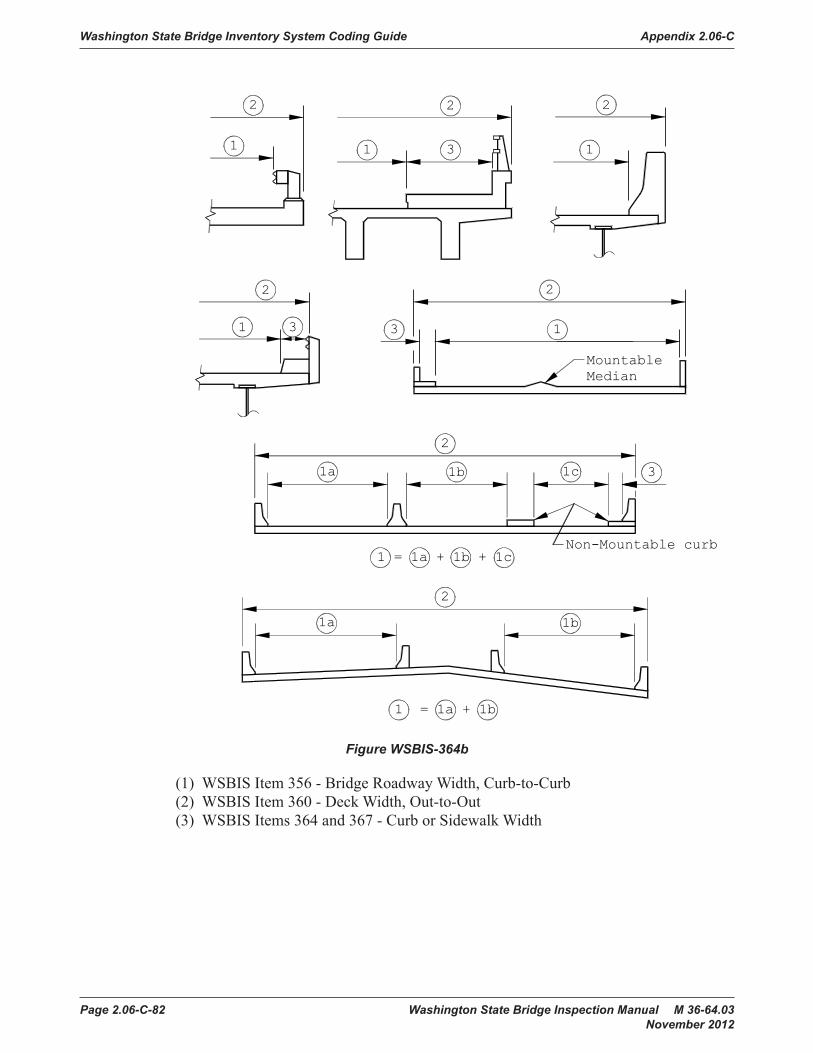
Washington State Bridge Inventory System Coding Guide Appendix 2.06-C
Page 2.06-C-82 Washington State Bridge Inspection Manual M 36-64.03 November 2012
2
1a 1b
1 = 1a + 1b
2
1a 1b 1c
1 = 1a + 1b + 1c
2
311
2
1
2
2
1 3
3
Non-Mountable curb
MountableMedian
2
13
Figure WSBIS-364b
(1) WSBIS Item 356 - Bridge Roadway Width, Curb-to-Curb(2) WSBIS Item 360 - Deck Width, Out-to-Out(3) WSBIS Items 364 and 367 - Curb or Sidewalk Width

Appendix 2.06-C Washington State Bridge Inventory System Coding Guide
Washington State Bridge Inspection Manual M 36-64.03 Page 2.06-C-83 November 2012
Curb orSidewalk
Before Rail Retrofit After Rail RetrofitCode curb/sidewalkLeft of Right zero
No longerusable as curbor sidewalk
Figure WSBIS-364c
Null Status: Cannot be null.
Coding Requirements:Coded for Main Listing ‘on’ record: Yes, both for NBI and WSBISCoded for Main Listing ‘under’ record: Yes, for WSBIS onlyCoded for Secondary Listing ‘under’ record: No (data included with Main Listing ‘on’ record)Crossing record match: Identical for all crossing records
WSBIS Item 370 – Minimum Vertical Clearance Over Deck (XXXX feet and inches)
FHWA Item 53 – Minimum Vertical Clearance Over Bridge Roadway
Table: tblBridgesField Name: min_vert_deckData Type: numeric
The information to be recorded for this item is the actual minimum vertical clearance over the bridge roadway, including shoulders, to any superstructure restriction (excluding sign structures), in feet and inches, rounded to the lesser inch (e.g., 16′-3¾″ is to be coded 1603). For double decked structures code the minimum, regardless whether it is pertaining to the top or bottom deck. When no superstructure restriction exists above the bridge roadway code 9999. When a restriction is 100 feet or greater code 9912.

Washington State Bridge Inventory System Coding Guide Appendix 2.06-C
Page 2.06-C-84 Washington State Bridge Inspection Manual M 36-64.03 November 2012
16'-3"
CURB LINE
FOG LINE
CURB LINE
FOG LINE
16'-9"
FOG LINE
FOG LINE
CURB LINE
CURB LINE
CENTER LINE
18'-6"
STEEL TRUSS EXAMPLE
LANELANE17'-5"
17'-9"
16'-7"
16'-11"
16'-3"
16'-5"
16'-9"
CENTER LINE
LANELANE
BRIDGE OVER BRIDGE EXAMPLECode: 1603
Code: 1603
BOTTOM OF GIRDER
INVENTORIED BRIDGE
Figure WSBIS-370
Null Status: Cannot be null.
Coding Requirements:Coded for Main Listing ‘on’ record: Yes, both for NBI and WSBISCoded for Main Listing ‘under’ record: Yes, for WSBIS onlyCoded for Secondary Listing ‘under’ record: No (data included with Main Listing ‘on’ record)Crossing record match: Identical for all crossing records
WSBIS Item 374 – Minimum Vertical Clearance Under Bridge (XXXX feet and inches)
FHWA Item 54B – Minimum Vertical Underclearance
Table: tblBridgesField Name: min_vert_underData Type: numeric
Code the minimum vertical clearance from the roadway (travel lanes only) or railroad track beneath the structure to the underside of the superstructure. Traveled way, or travel lanes, is between fog lines and excludes shoulders or gore areas.
If the bridge crosses both a highway and a railroad, code the highway clearance UNLESS the railroad has a substandard clearance based on current design criteria and the roadway is NOT substandard.
The information to be recorded is the actual minimum vertical clearance over the traveled way to the structure, in feet and inches, rounded to the lesser inch (e.g., 16′-3¾″ is to be coded 1603). When a restriction is 100 feet or greater, code 9912.
If the feature is not a highway or railroad, code the minimum vertical clearance 0.

Appendix 2.06-C Washington State Bridge Inventory System Coding Guide
Washington State Bridge Inspection Manual M 36-64.03 Page 2.06-C-85 November 2012
Top ofRail
Bottom of girder
Top ofRail
LANE LANE
DIVIDED HIGHWAY EXAMPLE
LANE LANE 16'-6"
17'-0"
17'-6"
EOP
EOP
17'-4"
FOG LINE
16'-8"
FOG LINE
15'-9"
16'-5"
16'-9"
EOP
EOP
16'-7"
FOG LINE
16'-3"
FOG LINE
CENTER LINE
CENTER LINE
FOG LINE
FOG LINE
CURB LINE
CURB LINE
CENTER LINE
16'-7"
16'-11"
16'-3"
16'-1"
16'-9"
LANELANE
BRIDGE OVER BRIDGE EXAMPLE
Code: 1603
Code: 1603
Code: 1603
Code: 1603
CURB LINE CURB LINE
FOG LINE FOG LINE
15'-9" 15'-9"
CENTER LINE
16'-3"
16'-3"
18'-5"
LANELANE
TUNNEL EXAMPLE
CENTER LINE
17'-0"
15'-9"
15'-9"
CURB LINE
CURB LINE
LANE LANE
UNDIVIDED HIGHWAY EXAMPLE
16'-3"
FOG LINE
16'-3"
FOG LINE
16'-3"
RAIL ROAD EXAMPLECode: 1603
16'-3"
BOTTOM OF GIRDER
INVENTORIED BRIDGE
Figure WSBIS-374
Null Status: Cannot be null.
Coding Requirements:Coded for Main Listing ‘on’ record: Yes, both for NBI and WSBISCoded for Main Listing ‘under’ record: Yes, for WSBIS onlyCoded for Secondary Listing ‘under’ record: No (data included with Main Listing ‘on’ record)Crossing record match: Identical for all crossing records

Washington State Bridge Inventory System Coding Guide Appendix 2.06-C
Page 2.06-C-86 Washington State Bridge Inspection Manual M 36-64.03 November 2012
WSBIS Item 378 – Vertical Underclearance Code
FHWA Item 54A – Reference feature
Table: tblBridgesField Name: vert_under_codeData Type: varchar
Code the reference feature from which the clearance measurement is taken:
Code DescriptionH Highway beneath structureR Railroad beneath structureN Feature not a highway or railroad
Null Status: Cannot be null.
Coding Requirements:Coded for Main Listing ‘on’ record: Yes, both for NBI and WSBISCoded for Main Listing ‘under’ record: Yes, for WSBIS onlyCoded for Secondary Listing ‘under’ record: No (data included with Main Listing ‘on’ record)Crossing record match: Identical for all crossing records
WSBIS Item 379 – Minimum Lateral Underclearance Right (XX.X feet)
FHWA Item 55B – Minimum Lateral Underclearance on Right
Table: tblBridgesField Name: lateral_route_rightData Type: numeric
The purpose of this item is to identify the lateral restrictions caused by the structure on the railroad or roadway underneath.
Code the minimum lateral underclearance on the right to the nearest tenth of a foot. When both a railroad and highway are under the structure, code the most critical dimension.
The lateral clearance should be measured from the right edge of the roadway excluding shoulders(fog line) or from the centerline (between rails) of the righthand track of a railroad to the nearest substructure unit (pier, abutment, etc.), a retaining wall or to a slope. The right/left orientation is based on traffic direction. The clearance measurements to be recorded will be the minimum after measuring the clearance in both directions of travel, perpendicular to the centerline of the undercrossing.
If two related features are below the bridge, measure both and record the lesser of the two. An explanation should be written on the inspection form as to what was recorded. When the clearance is 100 feet or greater, code 99.9.
If the feature beneath the structure is not a railroad or highway, code 0 to indicate not applicable.
The presence of ramps and acceleration or turning lanes is not considered in this item; therefore, the minimum lateral clearance on the right should be measured from the right edge of the through roadway.

Appendix 2.06-C Washington State Bridge Inventory System Coding Guide
Washington State Bridge Inspection Manual M 36-64.03 Page 2.06-C-87 November 2012
PARKING
STRIPE
PARKING
STRIPE
CITY STREET EXAMPLE
16.0'14.6'
* *
TYPICAL PLAN VIEW
Measure lateral under clearancePerpendicular to inventory routeunder Structure at Minimum "X"Locations.
X
X
Route Under
Structure
7.2' OPEN 8.2'
RT. = 7.2 Lt. = 999
FREEWAY OPEN MEDIAN EXAMPLE
FOG LINE
FOG LINE
FOG LINE
FOG LINE
12.3'
2-way traffic: RT. = 11.6 LT. = ØØØ1-way traffic looking in the directionof traffic: RT. = 12.3 LT. = 11.6
HIGHWAY EXAMPLEFOG LINE
FOG LINE
11.6'
2-way traffic: RT. = 12.9 LT. = ØØØ1-way traffic looking in the directionof traffic: RT. = 14.3 LT. = 12.9
MULTIPLE LEVEL INTERCHANGE EXAMPLE
FOG LINE
12.9'
FOG LINE
14.3'
RT. = 6.4 Lt. = 7.0
FREEWAY PIER MEDIAN EXAMPLE
FOG LINE
FOG LINE
FOG LINE
FOG LINE
6.9' 7.6'7.0' 6.4'
2-way traffic: RT. = 14.6 LT. = ØØØ1-way traffic looking in the direction oftraffic: RT. = 16.0 LT. = 14.6* = Parking area, Inspectors please document Dimension.
7.2' OPEN 8.2'
RT. = 7.2 Lt. = 999
DUAL HIGHWAY OPEN MEDIAN EXAMPLE
FOG LINE
FOG LINE
FOG LINE
FOG LINE
RT. = 6.4 Lt. = 7.0(For LT. greater than 100'-0" CODE 998)
DUAL HIGHWAY PIER MEDIAN EXAMPLE
FOG LINE
FOG LINE
FOG LINE
FOG LINE
6.9' 7.6'7.0' 6.4'CENTER LINE
CENTER LINE
CENTER LINE
CENTER LINE
ROUTE YROUTE X
ROUTE X ROUTE Y
ROUTE X ROUTE X ROUTE X
ROUTE X ROUTE X
ROUTE X
ROUTE X
Figure WSBIS-379a

Washington State Bridge Inventory System Coding Guide Appendix 2.06-C
Page 2.06-C-88 Washington State Bridge Inspection Manual M 36-64.03 November 2012
¢ ¢
RT. = 10.2 Lt. = ØØØ
RAILROAD MULTIPLE TRACK EXAMPLE
10.2' 12.6'
R/R R/R
RT. = 12.3 Lt. = 11.6
¢
RT. = 14.2 Lt. = ØØØ
RAILROAD SINGLE TRACK EXAMPLE
14.2'21.5'R/R
Retaining wall
12.3'
HIGHWAY WITH RETAINING WALL EXAMPLE
FOG LINE
FOG LINE
11.6'
ROUTE X
40.0'
HIGHWAY ON/OFF RAMP EXAMPLE
FOG LINE
GORE/FOG LINE
GORE/FOG LINE
FOG LINE
11.5'
ROUTE XON/OFFRAMP
2-way traffic: RT. = 11.5 LT. = ØØØ1-way traffic looking in the directionof traffic: RT. = 40.0 LT. = 11.5
Figure WSBIS-379b
Null Status: Cannot be null.
Coding Requirements:Coded for Main Listing ‘on’ record: Yes, both for NBI and WSBISCoded for Main Listing ‘under’ record: NoCoded for Secondary Listing ‘under’ record: No (data included with Main Listing ‘on’ record)Crossing record match: Identical for all crossing records
NBI Commentary:The NBI coding guide text and drawings are not clear or consistent, particularly with respect to determining whether or not the lateral measurements extend to guardrails, concrete rails, non-mountable curbs, substructure units, or slopes. Attempts to define the steepness of slopes was also problematic This coding guide clarifies that all measurements are to substructure units or “slopes” without defining the steepness. In addition, the NBI coding guide was not entirely clear about how to code dual highways in relation to substructure units or medians. This coding guide clarifies this through illustration.

Appendix 2.06-C Washington State Bridge Inventory System Coding Guide
Washington State Bridge Inspection Manual M 36-64.03 Page 2.06-C-89 November 2012
WSBIS Item 382 – Lateral Underclearance Code
FHWA Item 55A – Minimum Lateral Underclearance on Right
Table: tblBridgesField Name: lateral_route_codeData Type: varchar
This code identifies the type of reference feature from which the clearance measurement is taken.
Code DescriptionH Highway beneath structureR Railroad beneath structureN Feature beneath the bridge is neither a highway or railroad
WSBIS Item 383 – Minimum Lateral Underclearance Route Left (XX.X feet)
FHWA Item 56 – Minimum Lateral Underclearance on Left
Table: tblBridgesField Name: lateral_route_leftData Type: numeric
The purpose of this code is to identify the lateral restrictions caused by the structure on the railroad or roadway underneath.
This field is intended to record measurements on the left side of highway based on traffic direction for divided highways, 1 way streets, and ramps. For railroads and all 2 direction, 2 lane routes which are undivided, code 000.
Code the minimum lateral underclearance on the left (median side for divided highways) to the nearest tenth of a foot. The lateral clearance should be measured from the left edge of the roadway (excluding shoulders) to the nearest substructure unit, or to a slope. Refer to examples for WSBIS Item 379 - Minimum Lateral Underclearance on Right.
For clearances greater than 100 feet, code 99.8.
In cases where there is an open median (no piers in median), code 99.9.
Code 0 to indicate not applicable (railroads and other non highway undercrossings).
Null Status: Cannot be null.
Coding Requirements:Coded for Main Listing ‘on’ record: Yes, both for NBI and WSBISCoded for Main Listing ‘under’ record: NoCoded for Secondary Listing ‘under’ record: No (data included with Main Listing ‘on’ record)Crossing record match: Identical for all crossing records
NBI Commentary:See WSBIS Item 379 commentary.
Washington State Bridge Inventory System Coding Guide Appendix 2.06-C
Page 2.06-C-90 Washington State Bridge Inspection Manual M 36-64.03 November 2012
WSBIS Item 386 – Navigation Control
FHWA Item 38 – Navigation Control
Table: tblBridgesField Name: nav_control_codeData Type: varchar
Indicate for this item whether or not navigation control (a bridge permit for navigation) is required. Use one of the following codes:
Code DescriptionN Not applicable, no waterway0 No navigation control on waterway (bridge permit not required or bridge crossing
an advance approval waterway)1 Navigation control on waterway (bridge permit required)
Code 0 for bridges that cross Advance Approval Waterways (Title 33, Code of Federal Regulations, Section 115.70, as amended). These are waterways for which the Commandant, U.S. Coast Guard has given advance approval to the location and plans of bridges to be constructed across reaches of waterways navigable-in-law, but not actually navigated other than by logs, log rafts, rowboats, canoes and small motorboats.
Null Status: Cannot be null.
Coding Requirements:Coded for Main Listing ‘on’ record: Yes, both for NBI and WSBISCoded for Main Listing ‘under’ record: Yes, only for WSBISCoded for Secondary Listing ‘under’ record: No (data included with Main Listing ‘on’ record)Crossing record match: Identical for all crossing records
NBI Commentary:This coding guide provides additional guidance on how to code bridges crossing advance approval waterways as defined in Title 33CFR Section 115.70
WSBIS Item 387 – Navigation Vertical Clearance (XXX feet)
FHWA Item 39 – Navigation Vertical Clearance
Table: tblBridgesField Name: nav_vert_clrncData Type: numeric
If WSBIS Item 386 - Navigation Control has been coded 1, record the minimum vertical clearance imposed at the site as measured above a datum that is specified on a navigation permit issued by a control agency. The measurement shall be coded to the foot. This measurement will show the clearance that is allowable for navigational purposes. In the case of a swing or bascule bridge, the vertical clearance shall be measured with the bridge in the closed position (i.e., open to vehicular traffic).

Appendix 2.06-C Washington State Bridge Inventory System Coding Guide
Washington State Bridge Inspection Manual M 36-64.03 Page 2.06-C-91 November 2012
The vertical clearance of a vertical lift bridge shall be measured with the bridge in the raised or open position. Also, WSBIS Item 394 - Vertical Lift Minimum Navigation Clearance shall be coded to provide clearance in a closed position. If WSBIS Item 386 - Navigation Control has been coded 0 or N, code 0 to indicate not applicable.
Null Status: Cannot be null.
Coding Requirements:Coded for Main Listing ‘on’ record: Yes, both for NBI and WSBISCoded for Main Listing ‘under’ record: Yes, only for WSBISCoded for Secondary Listing ‘under’ record: No (data included with Main Listing ‘on’ record)Crossing record match: Identical for all crossing records
WSBIS Item 390 – Navigation Horizontal Clearanc (XXXX feet)
FHWA Item 40 – Navigation Horizontal Clearance
Table: tblBridgesField Name: nav_horiz_clrncData Type: numeric
If WSBIS Item 386 - Navigation Control has been coded 1, record the horizontal clearance measurement imposed at the site that is shown on the navigation permit. This may be less than the structure geometry allows. If a navigation permit is required but not available, use the minimum horizontal clearance between fenders, if any, or the clear distance between piers or bents. Code the clearance to the foot. If WSBIS Item 386 - Navigation Control has been coded 0 or N, code 0 to indicate not applicable.
Null Status: Cannot be null.
Coding Requirements:Coded for Main Listing ‘on’ record: Yes, both for NBI and WSBISCoded for Main Listing ‘under’ record: Yes, only for WSBISCoded for Secondary Listing ‘under’ record: No (data included with Main Listing ‘on’ record)Crossing record match: Identical for all crossing records
WSBIS Item 394 – Vertical Lift Minimum Navigation Clearance (XXX feet)
FHWA Item 116 – Minimum Navigation Vertical Clearance, Vertical Lift Bridge
Table: tblBridgesField Name: vert_lift_min_clrncData Type: numeric
Code the minimum vertical clearance to the nearest lesser foot imposed at the site as measured above a datum that is specified on a navigation permit issued by a control agency.
Null Status: Code this item only for vertical lift bridges in the dropped or closed position, otherwise leave blank.

Washington State Bridge Inventory System Coding Guide Appendix 2.06-C
Page 2.06-C-92 Washington State Bridge Inspection Manual M 36-64.03 November 2012
Coding Requirements:Coded for Main Listing ‘on’ record: Yes, both for NBI and WSBISCoded for Main Listing ‘under’ record: NoCoded for Secondary Listing ‘under’ record: No (data included with Main Listing ‘on’ record)Crossing record match: Varies as needed for crossing records
WSBIS Item 397 – Approach Roadway Width (XXX feet)
FHWA Item 32 – Approach Roadway Width
Table: tblBridgesField Name: aprch_widthData Type: numeric
Code the normal width of usable roadway approaching the structure measured to the nearest foot. Usable roadway width will include the width of traffic lanes and the widths of shoulders where shoulders are defined as follows:
Shoulders must be constructed and normally maintained flush with the adjacent traffic lane, and must be structurally adequate for all weather and traffic conditions consistent with the facility carried. Unstabilized grass or dirt, with no base course, flush with and beside the traffic lane, is not to be considered a shoulder for this item.
For structures with medians of any type and doubledecked structures, this item should be coded as the sum of the usable roadway widths for the approach roadways (i.e., all median widths which do not qualify as shoulders should not be included in this dimension). When there is a variation between the approaches at either end of the structure, code the most restrictive of the approach conditions.
Regardless of whether the median is open or closed, the data coded must be compatible with the other related route and bridge data (e.g., if WSBIS Item 356 - Curb-to-Curb is for traffic in one direction only, then Lanes On, ADT, etc., must be for traffic in one direction only).
If a ramp is adjacent to the through lanes approaching the structure, it shall be included in the approach roadway width.
Null Status: Cannot be null
Coding Requirements:Coded for Main Listing ‘on’ record: Yes, both for NBI and WSBISCoded for Main Listing ‘under’ record: Yes, for WSBIS onlyCoded for Secondary Listing ‘under’ record: No (data included with Main Listing ‘on’ record)Crossing record match: Identical for all crossing records

Appendix 2.06-C Washington State Bridge Inventory System Coding Guide
Washington State Bridge Inspection Manual M 36-64.03 Page 2.06-C-93 November 2012
WSBIS Item 3100 – Skew (XX degrees)
FHWA Item 34 – Skew
Table: tblBridgesField Name: nominal_skew_angleData Type: numeric
The skew angle is the angle between the centerline of a pier and a line normal to the roadway centerline. When plans are available, the skew angle can be taken directly from the plans. If no plans are available, the angle is to be field measured if possible. Record the skew angle to the nearest degree. If the skew angle is zero (bridge piers perpendicular to roadway centerline), it should be so coded. When the structure is on a curve or if the skew varies for some other reason, the average skew should be recorded, if reasonable. Otherwise, record 99 to indicate a major variation in skews of substructure units. A 2-digit number should be coded.
Skew Angle
Figure WSBIS-3100
Null Status: Cannot be null
Coding Requirements:Coded for Main Listing ‘on’ record: Yes, both for NBI and WSBISCoded for Main Listing ‘under’ record: Yes, for WSBIS onlyCoded for Secondary Listing ‘under’ record: No (data included with Main Listing ‘on’ record)Crossing record match: Identical for all crossing records

Washington State Bridge Inventory System Coding Guide Appendix 2.06-C
Page 2.06-C-94 Washington State Bridge Inspection Manual M 36-64.03 November 2012
WSBIS Item 3102 – Flared Flag
FHWA 35 – Structure Flared
Table: tblBridgesField Name: flared_flagData Type: varchar
Code this item to indicate if the structure is flared (i.e., the width of the structure varies). Generally, such variance will result from ramps converging with or diverging from the through lanes on the structure, but there may be other causes. Minor flares at ends of structures should be ignored.
WSDOT Code NBI Code DescriptionN 0 No flareY 1 Yes flared
Null Status: Cannot be null
Coding Requirements:Coded for Main Listing ‘on’ record: Yes, both for NBI and WSBISCoded for Main Listing ‘under’ record: Yes, for WSBIS onlyCoded for Secondary Listing ‘under’ record: No (data included with Main Listing ‘on’ record)Crossing record match: Identical for all crossing records
NBI Commentary:WSDOT codes Y and N, which is translated to 1 and 0 for NBI reporting.

Appendix 2.06-C Washington State Bridge Inventory System Coding Guide
Washington State Bridge Inspection Manual M 36-64.03 Page 2.06-C-95 November 2012
WSBIS Item 0000 – Main Listing Flag
See Coding Guide Clarifications for a description of the Main Listing Flag. Note that this item is maintained by the Information Group and is visible in the BridgeWorks Inventory Management mode.
WSBIS Items 432, 433, 434, and 435
FHWA Item 5 – Inventory Route
The inventory route is a 9-digit code composed of 5 segments.
Segment Description5A Record Type5B Route Signing Prefix5C Designated Level of Service5D Route Number5E Directional Suffix
WSBIS Item 432 – Inventory Route On/Under
FHWA 5A – Record type
Table: tblCrossingField Name: on_under_codeData Type: varchar
There are two types of National Bridge Inventory records: ‘on’ and ‘under’. Code the first digit (leftmost) using one of the following codes:
Code Description1 Route carried ‘on’ the structure2 Single route goes ‘under’ the structure
A – Z Multiple routes go ‘under’ the structure
‘On’ signifies that the inventory route is carried on the structure. Each bridge structure carrying highway traffic must have a record identified with a type code = 1. All of the NBI data items must be coded, unless specifically excepted, with respect to the structure and the inventory route on it.
‘Under’ signifies that the inventory route goes under the structure. If an inventory route beneath the structure is a Federal-aid highway, is a STRAHNET route or connector or is otherwise important, a record must be coded to identify it. The type code must be 2 or an alphabetic letter A through Z. Code 2 for a single route under the structure. If 2 or more routes go under a structure on separate roadways, the code of 2 shall not be used. Code A, B, C, D, etc., consecutively for multiple routes on separate roadways under the same structure. STRAHNET routes shall be listed first. When this item is coded 2 or A through Z, only selected items are coded, as specified in the item descriptions and in the list in the Coding Guide Clarifications.

Washington State Bridge Inventory System Coding Guide Appendix 2.06-C
Page 2.06-C-96 Washington State Bridge Inspection Manual M 36-64.03 November 2012
It cannot be overemphasized that all route-oriented data must agree with the coding as to whether the inventory route is on or under the structure.
Tunnels shall be coded only as an ‘under’ record; that is, they shall not be coded as a structure carrying highway traffic.
There are situations of a route under a structure, where the structure does not carry a highway, but may carry a railroad, pedestrian traffic, or even a building. These are coded the same as any other ‘under’ record and no ‘on’ record shall be coded.
For additional clarification of ‘on’ and ‘under’ records, refer to the Coding Guide Instructions.
Null Status: Cannot be null
Coding Requirements:Coded for Main Listing ‘on’ record: Yes, both for NBI and WSBISCoded for Main Listing ‘under’ record: Yes, both for NBI and WSBISCoded for Secondary Listing ‘under’ record: Yes, both for NBI and WSBISCrossing record match: Unique for all crossing records
WSBIS Item 433 – Inventory Route Highway Class
FHWA Item 5B – Route Signing Prefix
Table: tblCrossingField Name: hwy_classData Type: varchar
Identify the route signing prefix for the inventory route using one of the following codes:
Code Description1 Interstate highway2 U.S. numbered highway3 State highway4 County road5 City street6 Federal lands road7 State lands road8 Other (include toll roads not otherwise identifiable above)
When 2 or more routes are concurrent, the highest class of route will be used. The hierarchy is in the order listed above.
Null Status: Cannot be null
Coding Requirements:Coded for Main Listing ‘on’ record: Yes, both for NBI and WSBISCoded for Main Listing ‘under’ record: Yes, both for NBI and WSBISCoded for Secondary Listing ‘under’ record: Yes, both for NBI and WSBISCrossing record match: Varies as needed for crossing records

Appendix 2.06-C Washington State Bridge Inventory System Coding Guide
Washington State Bridge Inspection Manual M 36-64.03 Page 2.06-C-97 November 2012
WSBIS Item 434 – Inventory Route Service Level
FHWA Item 5C – Designated Level of Service
Table: tblCrossingField Name: serv_level_codeData Type: varchar
Identify the designated level of service for the inventory route using one of the following codes:
Code Description1 Mainline (includes reversible routes)2 Alternate3 Bypass4 Spur6 Business7 Ramp, Wye, Connector, etc.8 Service and/or unclassified frontage road0 None of the above
Null Status: Cannot be null
Coding Requirements:Coded for Main Listing ‘on’ record: Yes, both for NBI and WSBISCoded for Main Listing ‘under’ record: Yes, both for NBI and WSBISCoded for Secondary Listing ‘under’ record: Yes, both for NBI and WSBISCrossing record match: Varies as needed for crossing records
WSBIS Item 435 – Route
FHWA Item 5D – Route Number
Table: tblCrossingField Name: inv_routeData Type: varchar
Code the route number of the inventory route in the next 5 positions. This value shall be right justified in the field with leading zeros filled in.
If concurrent routes are of the same hierarchy level, denoted by the route signing prefix, the lowest numbered route shall be coded. Code 00000 for bridges on roads without route numbers.
Null Status: Cannot be null
Coding Requirements:Coded for Main Listing ‘on’ record: Yes, both for NBI and WSBISCoded for Main Listing ‘under’ record: Yes, both for NBI and WSBISCoded for Secondary Listing ‘under’ record: Yes, both for NBI and WSBISCrossing record match: Varies as needed for crossing records.

Washington State Bridge Inventory System Coding Guide Appendix 2.06-C
Page 2.06-C-98 Washington State Bridge Inspection Manual M 36-64.03 November 2012
FHWA Item 5E – Directional Suffix
Washington State does not maintain directional suffixes to route numbers, so this information is not maintained in the Washington State Bridge Inventory. This code is not editable, and is automatically generated as 0 (not applicable) for the NBI text file.
WSBIS Item 440 – Milepost (XXX.XX) miles
Table: tblCrossingField Name: traffic_flowData Type: numeric
The milepost is displayed on the inspection report header with the associated route (WSBIS Item 435). Both are intended to provide information about the location of the bridge on the primary route used for inspection access, and should represent the bridge milepost relative to nearby milepost signs. In nearly all cases the route and milepost are based on the route coded in WSBIS Item 009 - Bridge Number. In rare instances a bridge number will be based on one route and the Route and Milepost will be based on another route.
Null Status: Cannot be null.
Coding Requirements:Coded for Main Listing ‘on’ record: Yes, for WSBIS onlyCoded for Main Listing ‘under’ record: Yes, for WSBIS onlyCoded for Secondary Listing ‘under’ record: Yes, for WSBIS onlyCrossing record match: Null for all secondary listings.
WSBIS Item 445 – ADT
FHWA Item 29 – Average Daily Traffic
Table: tblCrossingField Name: adtData Type: numeric
Code a 6-digit number that shows the average daily traffic volume for the inventory route. Make certain the unit’s position is coded even if estimates of ADT are determined to tens or hundreds of vehicles; that is, appropriate trailing zeros shall be coded. The ADT coded should be the most recent ADT counts available. Included in this item are the trucks referred to in WSBIS Item 451 - Average Daily Truck Traffic. If the bridge is closed, code the actual ADT from before the closure occurred.
The ADT must be compatible with the other items coded for the bridge. For example, parallel bridges with an open median are coded as follows: if WSBIS Item 352 - Lanes On the Structure and WSBIS Item 356 - Curb-to-Curb are coded for each bridge separately, then the ADT must be coded for each bridge separately (not the total ADT for the route).
ADT information is available at www.wsdot.wa.gov/mapsdata/tools/traffictrends/.

Appendix 2.06-C Washington State Bridge Inventory System Coding Guide
Washington State Bridge Inspection Manual M 36-64.03 Page 2.06-C-99 November 2012
Null Status: Cannot be null
Coding Requirements:Coded for Main Listing ‘on’ record: Yes, both for NBI and WSBISCoded for Main Listing ‘under’ record: Yes, both for NBI and WSBISCoded for Secondary Listing ‘under’ record: Yes, both for NBI and WSBISCrossing record match: Varies as needed for crossing records
WSBIS Item 451 – ADT Truck Percentage (XX percent)
FHWA Item 109 – Average Daily Truck Traffic
Table: tblCrossingField Name: adt_truck_pctData Type: numeric
Code the percentage of WSBIS Item 445 - Average Daily Traffic that is truck traffic on the inventory route. Do not include vans, pickup trucks and other light delivery trucks in this percentage.
Null Status: Cannot be null
Coding Requirements:Coded for Main Listing ‘on’ record: Yes, both for NBI and WSBISCoded for Main Listing ‘under’ record: Yes, both for NBI and WSBISCoded for Secondary Listing ‘under’ record: Yes, both for NBI and WSBISCrossing record match: Varies as needed for crossing records
WSBIS Item 453 – ADT Year
FHWA Item 30 – Year of Average Daily Traffic
Table: tblCrossingField Name: adt_yearData Type: numeric
Record the year represented by the ADT in WSBIS Item 445. Code all four digits of the year.
ADT Year information is available at the link in WSBIS Item 445.
Null Status: Cannot be null
Coding Requirements:Coded for Main Listing ‘on’ record: Yes, both for NBI and WSBISCoded for Main Listing ‘under’ record: Yes, both for NBI and WSBISCoded for Secondary Listing ‘under’ record: Yes, both for NBI and WSBISCrossing record match: Varies as needed for crossing records

Washington State Bridge Inventory System Coding Guide Appendix 2.06-C
Page 2.06-C-100 Washington State Bridge Inspection Manual M 36-64.03 November 2012
WSBIS Item 457 – Future ADT
FHWA Item 114 – Future Average Daily Traffic
Table: tblCrossingField Name: future_adtData Type: numeric
Code the forecasted average daily traffic (ADT) for the inventory route. This shall be projected at least 17 years but no more than 22 years from the last year of routine, short span, or safety inspection. If planning data is not available, use the best estimate based on site familiarity.
The future ADT must be compatible with the other items coded for the bridge. For example, parallel bridges with an open median are coded as follows: if WSBIS Item 352 - Lanes On the Structure and WSBIS Item 356 - Curb-to-Curb are coded for each bridge separately, then the future ADT must be coded for each bridge separately (not the total for the route).
Null Status: Cannot be null.
Coding Requirements:Coded for Main Listing ‘on’ record: Yes, both for NBI and WSBISCoded for Main Listing ‘under’ record: NoCoded for Secondary Listing ‘under’ record: NoCrossing record match: Varies as needed for crossing records
NBI Commentary:The WSDOT description clarifies that 17-22 year range is based on the year of inspection as defined in WSBIS Item 463.
WSBIS Item 463 – Future ADT Year
FHWA Item 115 – Year of Future Average Daily Traffic
Table: tblCrossingField Name: future_adt_yearData Type: numeric
Code the year represented by the future ADT in WSBIS Item 457. The projected year of future ADT shall be at least 17 years but no more than 22 years from the year of routine, short span, or safety inspection.
Null Status: Cannot be null.
Coding Requirements:Coded for Main Listing ‘on’ record: Yes, both for NBI and WSBISCoded for Main Listing ‘under’ record: NoCoded for Secondary Listing ‘under’ record: NoCrossing record match: Varies as needed for crossing records

Appendix 2.06-C Washington State Bridge Inventory System Coding Guide
Washington State Bridge Inspection Manual M 36-64.03 Page 2.06-C-101 November 2012
WSBIS Item 467 – Linear Referencing System Route
FHWA Item 13A – LRS Inventory Route Number
Table 13A: tblCrossingField Name: lrs_routeData Type: varchar
The LRS inventory route number reported must correspond to the LRS inventory route number reported by the State for the HPMS.
The LRS inventory route number is coded in the eleven positions, right justified and zero filled to the 10th digit. In most cases the 11th digit can remain blank, but if necessary it is used to provide the complete LRS route information.
Examples:599S500035529SPEVERET (reported to NBI as 529SPEVERE)
Null Status: Cannot be null
Coding Requirements:Coded for Main Listing ‘on’ record: Yes, both for NBI and WSBISCoded for Main Listing ‘under’ record: Yes, both for NBI and WSBISCoded for Secondary Listing ‘under’ record: Yes, both for NBI and WSBISCrossing record match: Varies as needed for crossing records
NBI Commentary:WSDOT maintains an 11 digit LRS route number, but the NBI has only 10 digits. In most cases WSDOT does not use the 11th digit, so the coding is intended to minimize data loss when the 11th digit is not used by leaving it as a blank field when possible.
WSBIS Item 477 – Linear Referencing System Sub Route
FHWA Item 13B – LRS Subroute Number
Table 13B: tblCrossingField Name: lrs_sub_routeData Type: varchar
The LRS subroute number is always coded 00.

Washington State Bridge Inventory System Coding Guide Appendix 2.06-C
Page 2.06-C-102 Washington State Bridge Inspection Manual M 36-64.03 November 2012
WSBIS Item W07 – LRS Milepost (XXX.XX) miles
FHWA Item 11 – Kilometerpoint
Table: tblCrossingField Name: lrs_traffic_flowData Type: numeric
The linear referencing system (LRS) milepoint is used to establish the location of the bridge on the Base Highway Network (see WSBIS Item 484). It must be from the same LRS Inventory Route and milepoint system as reported in the Highway Performance Monitoring System (HPMS). The milepoint coded in this item directly relates to WSBIS Item 477 - LRS Inventory Route, Subroute Number.
This item records the milepoint at the beginning of the structure (the lowest milepoint on the structure). When the LRS Inventory Route goes under the structure (WSBIS Item 432 coded 2 or A-Z), then code the milepoint on the underpassing route where the structure is first encountered.
Code to two decimal places. Code all zeros in this field if milepoints are not available.
Null Status: Cannot be null
Coding Requirements:Coded for Main Listing ‘on’ record: Yes, both for NBI and WSBISCoded for Main Listing ‘under’ record: Yes, both for NBI and WSBISCoded for Secondary Listing ‘under’ record: Yes, both for NBI and WSBISCrossing record match: Varies as needed for crossing records
WSBIS Item 483 – National Highway System
FHWA Item 104 – Highway System of the Inventory Route
Table: tblCrossingField Name: fed_hwy_system_codeData Type: varchar
This item is to be coded for all records in the inventory. For the inventory route identified in WSBIS Item 435, indicate whether the inventory route is on the National Highway System (NHS) or not on that system. Use one of the following codes:
Code Description0 Inventory Route is not on the NHS1 Inventory Route is on the NHS

Appendix 2.06-C Washington State Bridge Inventory System Coding Guide
Washington State Bridge Inspection Manual M 36-64.03 Page 2.06-C-103 November 2012
Null Status: Cannot be null
Coding Requirements:Coded for Main Listing ‘on’ record: Yes, both for NBI and WSBISCoded for Main Listing ‘under’ record: Yes, both for NBI and WSBISCoded for Secondary Listing ‘under’ record: Yes, both for NBI and WSBISCrossing record match: Varies as needed for crossing records
WSBIS Item 484 – Base Highway Network
FHWA Item 12 – Base Highway Network
Table: tblCrossingField Name: base_hwy_netData Type: varchar
This item is to be coded for all records in the inventory. The Base Highway Network includes the through lane (mainline) portions of the NHS, rural/urban principal arterial system and rural minor arterial system. Ramps, frontage roads and other roadways are not included in the Base Network. For the inventory route identified in WSBIS Item 435 - Inventory Route, indicate whether the inventory route is on the Base Highway Network or not on that network. Use one of the following codes:
Code Description0 Inventory Route is not on the Base Network1 Inventory Route is on the Base Network
Null Status: Cannot be null
Coding Requirements:Coded for Main Listing ‘on’ record: Yes, both for NBI and WSBISCoded for Main Listing ‘under’ record: Yes, both for NBI and WSBISCoded for Secondary Listing ‘under’ record: Yes, both for NBI and WSBISCrossing record match: Varies as needed for crossing records

Washington State Bridge Inventory System Coding Guide Appendix 2.06-C
Page 2.06-C-104 Washington State Bridge Inspection Manual M 36-64.03 November 2012
WSBIS Item 485 – STRAHNET Highway
FHWA Item 100 – STRAHNET Highway Designation
Table: tblCrossingField Name: strahnet_hwyData Type: varchar
This item shall be coded for all records in the inventory that are designated as part of the Strategic Highway Network. For the purposes of this item, the STRAHNET Connectors are considered included in the term STRAHNET. For the inventory route identified in WSBIS Item 435, indicate STRAHNET highway conditions using one of the following codes:
Code Description0 The inventory route is not a STRAHNET route1 The inventory route is on an Interstate STRAHNET route2 The inventory route is on a Non-Interstate STRAHNET route3 The inventory route is on a STRAHNET connector route
Null Status: Cannot be null
Coding Requirements:Coded for Main Listing ‘on’ record: Yes, both for NBI and WSBISCoded for Main Listing ‘under’ record: Yes, both for NBI and WSBISCoded for Secondary Listing ‘under’ record: Yes, both for NBI and WSBISCrossing record match: Varies as needed for crossing records
WSBIS Item 486 – Federal Lands Highways
FHWA Item 105 – Federal Lands Highways
Table: tblCrossingField Name: fed_lands_hwy_codeData Type: varchar
Code zeroes for this field.
Null Status: Cannot be null
Coding Requirements:Coded for Main Listing ‘on’ record: Yes, both for NBI and WSBISCoded for Main Listing ‘under’ record: Yes for WSBIS onlyCoded for Secondary Listing ‘under’ record: Yes for WSBIS onlyCrossing record match: Varies as needed for crossing records
NBI Commentary:WSDOT has not been able to identify a source for this data, and will code zeroes until an information source is identified.
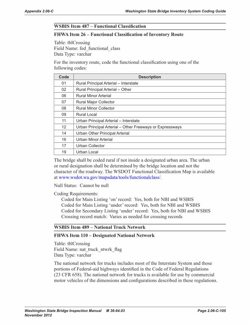
Appendix 2.06-C Washington State Bridge Inventory System Coding Guide
Washington State Bridge Inspection Manual M 36-64.03 Page 2.06-C-105 November 2012
WSBIS Item 487 – Functional Classification
FHWA Item 26 – Functional Classification of Inventory Route
Table: tblCrossingField Name: fed_functional_classData Type: varchar
For the inventory route, code the functional classification using one of the following codes:
Code Description01 Rural Principal Arterial – Interstate02 Rural Principal Arterial – Other06 Rural Minor Arterial07 Rural Major Collector08 Rural Minor Collector09 Rural Local11 Urban Principal Arterial – Interstate12 Urban Principal Arterial – Other Freeways or Expressways14 Urban Other Principal Arterial16 Urban Minor Arterial17 Urban Collector19 Urban Local
The bridge shall be coded rural if not inside a designated urban area. The urban or rural designation shall be determined by the bridge location and not the character of the roadway. The WSDOT Functional Classification Map is available at www.wsdot.wa.gov/mapsdata/tools/functionalclass/.
Null Status: Cannot be null
Coding Requirements:Coded for Main Listing ‘on’ record: Yes, both for NBI and WSBISCoded for Main Listing ‘under’ record: Yes, both for NBI and WSBISCoded for Secondary Listing ‘under’ record: Yes, both for NBI and WSBISCrossing record match: Varies as needed for crossing records
WSBIS Item 489 – National Truck Network
FHWA Item 110 – Designated National Network
Table: tblCrossingField Name: nat_truck_ntwrk_flagData Type: varchar
The national network for trucks includes most of the Interstate System and those portions of Federal-aid highways identified in the Code of Federal Regulations (23 CFR 658). The national network for trucks is available for use by commercial motor vehicles of the dimensions and configurations described in these regulations.

Washington State Bridge Inventory System Coding Guide Appendix 2.06-C
Page 2.06-C-106 Washington State Bridge Inspection Manual M 36-64.03 November 2012
For the inventory route identified in WSBIS Item 435, indicate conditions using one of the following codes:
WSDOT Code NBI Code DescriptionN 0 The inventory route is not part of the national network
for trucksY 1 The inventory route is part of the national network for trucks
Null Status: Cannot be null
Coding Requirements:Coded for Main Listing ‘on’ record: Yes, both for NBI and WSBISCoded for Main Listing ‘under’ record: Yes, both for NBI and WSBISCoded for Secondary Listing ‘under’ record: Yes, both for NBI and WSBISCrossing record match: Varies as needed for crossing records
NBI Commentary:WSDOT codes Y and N where the NBI codes are 1 and 0 respectively. This field is translated to NBI codes in the NBI text file.
490 – Lane Use Direction
FHWA Item 102 – Direction of Traffic
Table: tblCrossingField Name: lane_direction_codeData Type: varchar
Code the direction of traffic of the inventory route identified in WSBIS Item 435 as a 1-digit number using one of the codes below. This item must be compatible with other traffic-related items such as WSBIS Item 352 - Lanes on the Structure, WSBIS Item 445 - Average Daily Traffic, WSBIS Item 491 - Total Horizontal Clearance and WSBIS Item 356 - Curb-to-Curb.
WSDOT Code NBI Code Description0 0 No highway traffic on inventory route1 1 1 way traffic on inventory route2 2 2 way traffic on inventory route3 2 2 way and reversible traffic on inventory route4 1 Reversible traffic only on inventory route5 3 2 way traffic on 1 lane bridge (curb-to-curb must be <16 ft.)
Null Status: Cannot be null
Coding Requirements:Coded for Main Listing ‘on’ record: Yes, both for NBI and WSBISCoded for Main Listing ‘under’ record: Yes, both for NBI and WSBISCoded for Secondary Listing ‘under’ record: Yes, both for NBI and WSBISCrossing record match: Varies as needed for crossing records

Appendix 2.06-C Washington State Bridge Inventory System Coding Guide
Washington State Bridge Inspection Manual M 36-64.03 Page 2.06-C-107 November 2012
NBI Commentary:WSDOT provides additional codes to address reversible traffic lanes, which are translated to NBI codes as shown above.
WSBIS Item 354 – Lanes Under
FHWA Item 28B – Lanes Under the Structure
Table: tblCrossingField Name: lane_under_qtyData Type: numeric
Code the number of lanes under the structure.
For ‘on’ records, code WSBIS Item 354 for all lanes under the bridge for all routes that are functionally classified (see WSBIS Item 487).
For ‘under’ records, code WSBIS Item 354 for only the lanes under the bridge associated with the inventory route.
Include all lanes carrying highway traffic (e.g., cars, trucks, buses) which are striped or otherwise operated as a full width traffic lane for the entire length of the structure on or under the structure. This shall include any full width merge lanes and ramp lanes, and shall be independent of directionality of usage (e.g., a 1-lane bridge carrying 2-directional traffic is still considered to carry only one lane on the structure).
Null Status: Cannot be null
Coding Requirements:Coded for Main Listing ‘on’ record: Yes, both for NBI and WSBISCoded for Main Listing ‘under’ record: Yes, both for NBI and WSBISCoded for Secondary Listing ‘under’ record: Yes, both for NBI and WSBISCrossing record match: Varies as needed for crossing records.
NBI Commentary:This coding guide simplified and clarified the NBI coding guide text, but the intent was unchanged.

Washington State Bridge Inventory System Coding Guide Appendix 2.06-C
Page 2.06-C-108 Washington State Bridge Inspection Manual M 36-64.03 November 2012
WSBIS Item 491 – Horizontal Clearance, Route Direction (XXXX feet & inches)
FHWA Item 47 – Inventory Route, Total Horizontal Clearance
Table: tblCrossingField Name: horiz_clrnc_routeData Type: numeric
WSBIS Item 495 – Horizontal Clearance, Reverse Direction (XXXX feet & inches)
FHWA Item 47 – Inventory Route, Total Horizontal Clearance
Table: tblCrossingField Name: horiz_clrnc_rvrsData Type: numeric
The horizontal clearance for the inventory route should be measured and recorded for each opening between restrictive features – curbs, rails, guardrails, walls, piers, slopes, or other structural features limiting the roadway (surface and shoulders).
The purpose of this item is to give the largest available clearance for the movement of wide loads. Flush and mountable medians are not considered to be restrictions. This clearance is defined in two ways:
1. Clear distance between restrictions of the inventory route either on or under the structure.
2. Roadway surface and shoulders when there are no other restrictions.
When the entire inventory route passes through a single opening, code the measurement in WSBIS Item 491 and WSBIS Item 495 blank.
When the inventory route passes through multiple openings, code WSBIS Item 491 and WSBIS Item 495 for the mainline as appropriate.
When a restriction is 100 feet or greater, code 9912.

Appendix 2.06-C Washington State Bridge Inventory System Coding Guide
Washington State Bridge Inspection Manual M 36-64.03 Page 2.06-C-109 November 2012
Figure WSBIS-495
Null Status: Cannot both be null.
Coding Requirements:Coded for Main Listing ‘on’ record: Yes, both for NBI and WSBISCoded for Main Listing ‘under’ record: Yes, both for NBI and WSBISCoded for Secondary Listing ‘under’ record: Yes, both for NBI and WSBISCrossing record match: Varies as needed for crossing records
NBI Commentary:The NBI requires coding only the maximum horizontal clearance for divided highways. WSBIS has two fields. When the NBI submittal is prepared, the largest dimension is selected and reported.

Washington State Bridge Inventory System Coding Guide Appendix 2.06-C
Page 2.06-C-110 Washington State Bridge Inspection Manual M 36-64.03 November 2012
WSBIS Item 499 – Maximum Vertical Clearance Route Direction (XXXX feet & inches)
FHWA Item 10 – Inventory Route, Minimum Vertical Clearance
Table: tblCrossingField Name: vert_clrnc_route_maxData Type: numeric
Code the practical maximum vertical clearance over the inventory route identified in WSBIS Item 435, whether the route is on the structure or under the structure. This field identifies the minimum vertical clearance for the lane that will carry the highest load, regardless of the direction of travel. When no restriction exists leave this item blank. When the restriction is 100 feet or greater code 9912.
To accurately code this field, all vertical clearance measurements for the inventory route must be collected over all lane stripes and at edges of pavement, recorded in a vertical clearance card, and kept on file.
Example:
17'-0"
15'-6"
15'-6"
CURB LINE
CURB LINE
LANE LANE
LANE LANE
DIVIDED HIGHWAY EXAMPLE
LANE LANE
UNDIVIDED HIGHWAY EXAMPLE
16'-3"
FOG LINE
16'-3"
FOG LINE
CENTER LINE
Code "1603": The maximum vertical height allowed in any 10foot roadway width is the least vertical clearancein the lane of roadway with the maximum verticalclearance.
15'-9"
16'-3"
16'-9"
EOP
EOP
16'-6"
FOG LINE
16'-0"
FOG LINE
14'-6"
15'-0"
15'-6"
EOP
EOP
15'-3"
FOG LINE
14'-9"
FOG LINE
CENTER LINE
15'-6"
CURB LINE
FOG LINE
CURB LINE
FOG LINE
15'-9"
CENTER LINE
17'-6"
STEEL TRUSS EXAMPLE
LANELANE16'-1"
16'-3"
CENTER LINE
Figure WSBIS-499

Appendix 2.06-C Washington State Bridge Inventory System Coding Guide
Washington State Bridge Inspection Manual M 36-64.03 Page 2.06-C-111 November 2012
Null Status: Null when no restriction exists.
Coding Requirements:Coded for Main Listing ‘on’ record: Yes, both for NBI and WSBISCoded for Main Listing ‘under’ record: Yes, both for NBI and WSBISCoded for Secondary Listing ‘under’ record: Yes, both for NBI and WSBISCrossing record match: Varies as needed for crossing records
NBI Commentary:The NBI coding guide indicates that this measurement should be the minimum clearance for a 10 foot width of pavement or travelled part of the roadway. However, from a practical perspective this has been interpreted in this coding guide as the clearance for the lane that will pass the tallest load. The lanes are defined by striping, gutterlines or barriers.
WSBIS Item 4103 – Detour Length (XX miles)
FHWA Item 19 – Bypass, Detour Length
Table: tblCrossingField Name: detour_lengthData Type: numeric
Indicate the actual length to the nearest mile of the detour length, which is considered the additional travel needed to return to the original route if the bridge is closed.
If a ground level bypass is available at the structure site for the inventory route (ramps at a diamond interchange, for example), code the detour length as 0.
If the detour exceeds 99 miles, code 99.
If the bridge is one of twin bridges and is not at an interchange, code 1 where the other twin bridge can be used as a temporary bypass with a reasonable amount of crossover grading.
Code 0 for routes under the structure, on the basis that a failed bridge over the route can be removed to allow passage.
To the extent practical, the detour route should match the capacity and functionality of the original route. When this is not possible the following minimum standards shall apply:
1. The detour route cannot have weight restrictions lower than the original route.
2. The detour route cannot have vertical clearance limits over the roadway lanes less than 14 feet 3 inches (as measured) unless the original route also has vertical clearance restrictions, in which case the detour cannot further restrict clearances.

Washington State Bridge Inventory System Coding Guide Appendix 2.06-C
Page 2.06-C-112 Washington State Bridge Inspection Manual M 36-64.03 November 2012
Route A Route ARoute B Ro
ute C
Not includedin detour length
Bridge Impassable
Detour Length
Figure WSBIS-4103
Null Status: Cannot be null
Coding Requirements:Coded for Main Listing ‘on’ record: Yes, both for NBI and WSBISCoded for Main Listing ‘under’ record: Yes, both for NBI and WSBISCoded for Secondary Listing ‘under’ record: Yes, both for NBI and WSBISCrossing record match: Varies as needed for crossing records
NBI Commentary:This coding guide provides additional direction on how to code routes under the structure, and additional criteria for determining acceptable detour routes.

Appendix 2.06-C Washington State Bridge Inventory System Coding Guide
Washington State Bridge Inspection Manual M 36-64.03 Page 2.06-C-113 November 2012
WSBIS Item 156 – Location
FHWA Item 9 – Location
Table: tblCrossingField Name: locationData Type: varchar
This item contains a narrative description of the bridge location for the inventory route. Descriptions should be oriented ahead on station whenever possible. Do not use city limits, as these boundaries may move. This item shall be left justified.
Examples:19.3 E JCT SR 20314.7 E MASON CO
This item is used to code the location for all Secondary Listings and is visible in BridgeWorks Inventory Management mode. Main Listings are coded on the WB71 tab.
Null Status: Cannot be null
Coding Requirements:Coded for Main Listing ‘on’ record: Yes, both for NBI and WSBIS (See WSBIS Item 156)Coded for Main Listing ‘under’ record: Yes, both for NBI and WSBIS (See WSBIS Item 156)Coded for Secondary Listing ‘under’ record: Yes, both for NBI and WSBISCrossing record match: Varies as needed for crossing records

Washington State Bridge Inventory System Coding Guide Appendix 2.06-C
Page 2.06-C-114 Washington State Bridge Inspection Manual M 36-64.03 November 2012

Appendix 2.06-C Washington State Bridge Inventory System Coding Guide
Washington State Bridge Inspection Manual M 36-64.03 Page 2.06-C-115 November 2012
WSBIS Item 532 – Main Span Material
FHWA Item 43A – Structure Type, Main, Kind of Material
Table: tblBridgesField Name: fed_main_material_codeData Type: varchar
Indicate the kind of material and/or design for the main span.
Code Description1 Concrete2 Concrete continuous3 Steel4 Steel continuous5 Prestressed and/or post-tensioned concrete 6 Prestressed and/or post-tensioned concrete continuous7 Wood or Timber8 Masonry9 Aluminum, Wrought Iron, or Cast Iron0 Other
WSBIS Item 533 – Main Span Design
FHWA Item 43B – Structure Type, Main, Type of Design
Table: tblBridgesField Name: fed_main_material_codeData Type: varchar
Indicate the predominant type of design and/or type of construction.

Washington State Bridge Inventory System Coding Guide Appendix 2.06-C
Page 2.06-C-116 Washington State Bridge Inspection Manual M 36-64.03 November 2012
Code Description01 Slab02 Stringer/Multibeam or Girder03 Girder and Floorbeam System04 Tee Beam05 Box Beam or Girders – Multiple06 Box Beam or Girders – Single or Spread07 Frame (except frame culverts)08 Orthotropic09 Truss – Deck10 Truss – Thru11 Arch – Deck12 Arch – Thru13 Suspension14 Stayed Girder15 Movable – Lift16 Movable – Bascule17 Movable – Swing18 Tunnel19 Culvert (includes frame culverts)20* Mixed types21 Segmental Box Girder22 Channel Beam (Bathtub Unit)00 Other
*Applicable only to approach spans – WSBIS Item 536
Examples:Wood or Timber Through Truss = 710Masonry Culvert = 819Steel Suspension = 313Continuous Concrete Multiple Box Girders = 205Simple Span Concrete Slab = 101Tunnel in Rock = 018
Null Status: Cannot be null.
Coding Requirements:Coded for Main Listing ‘on’ record: Yes, both for NBI and WSBISCoded for Main Listing ‘under’ record: Yes, both for NBI and WSBISCoded for Secondary Listing ‘under’ record: No (data included with Main Listing ‘on’ record)Crossing record match: Identical for all crossing records

Appendix 2.06-C Washington State Bridge Inventory System Coding Guide
Washington State Bridge Inspection Manual M 36-64.03 Page 2.06-C-117 November 2012
WSBIS Item 535 – Approach Span Material
FHWA Item 44A – Structure Type, Approach Spans, Kind of Material
Table: tblBridgesField Name: fed_aprch_material_codeData Type: varchar
Indicate the type of structure for the approach spans to a major bridge or for the spans where the structural material is different. The codes are the same as for WSBIS Item 532. However, code 0 if this item is not applicable. If the kind of material is varied, code the most predominant.
Null Status: Cannot be null.
Coding Requirements:Coded for Main Listing ‘on’ record: Yes, both for NBI and WSBISCoded for Main Listing ‘under’ record: Yes, for WSBIS onlyCoded for Secondary Listing ‘under’ record: No (data included with Main Listing ‘on’ record)Crossing record match: Identical for all crossing records
WSBIS Item 536 – Approach Span Design
FHWA Item 44B – Structure Type, Approach Spans, Type of Design
Table: tblBridgesField Name: fed_aprch_design_codeData Type: varchar
Indicate the type of structure for the approach spans to a major bridge or for the spans where the structural material is different. The codes are the same as for WSBIS Item 533. However, code 00 if this item is not applicable. Use code 20 when no one type of design and/or construction is predominant for the approach units.
Null Status: Cannot be null.
Coding Requirements:Coded for Main Listing ‘on’ record: Yes, both for NBI and WSBISCoded for Main Listing ‘under’ record: Yes, for WSBIS onlyCoded for Secondary Listing ‘under’ record: No (data included with Main Listing ‘on’ record)Crossing record match: Identical for all crossing records

Washington State Bridge Inventory System Coding Guide Appendix 2.06-C
Page 2.06-C-118 Washington State Bridge Inspection Manual M 36-64.03 November 2012
WSBIS Item 538 – Number of Main Spans
FHWA Item 45 – Number of Spans in Main Unit
Table: tblBridgesField Name: main_span_qtyData Type: numeric
Record the number of spans in the main or major unit. This item will include all spans of most bridges, the major unit only of a sizable structure, or a unit of material or design different from that of the approach spans. Drop-ins and cantilevers are counted separately.
Null Status: Cannot be null.
Coding Requirements:Coded for Main Listing ‘on’ record: Yes, both for NBI and WSBISCoded for Main Listing ‘under’ record: Yes, for WSBIS onlyCoded for Secondary Listing ‘under’ record: No (data included with Main Listing ‘on’ record)Crossing record match: Identical for all crossing records
WSBIS Item 541 – Number of Approach Spans
FHWA Item 46 – Number of Approach Spans
Table: tblBridgesField Name: aprch_span_qtyData Type: numeric
Record the number of approach spans to the major bridge, or the number of spans of material different from that of the major bridge.
If the bridge has no approach spans, enter zero.
Null Status: Cannot be null.
Coding Requirements:Coded for Main Listing ‘on’ record: Yes, both for NBI and WSBISCoded for Main Listing ‘under’ record: Yes, for WSBIS onlyCoded for Secondary Listing ‘under’ record: No (data included with Main Listing ‘on’ record)Crossing record match: Identical for all crossing records
NBI Commentary:This coding guide requires coding zeroes when there are no approach spans. The NBI coding guide doesn’t provide guidance.

Appendix 2.06-C Washington State Bridge Inventory System Coding Guide
Washington State Bridge Inspection Manual M 36-64.03 Page 2.06-C-119 November 2012
WSBIS Item 544 – Service On
FHWA Item 42A – Type of Service On Bridge
Table: tblBridgesField Name: serv_on_codeData Type: varchar
Code Description1 Highway2 Railroad3 Pedestrian-bicycle4 Highway-railroad5 Highway-pedestrian6 Overpass structure at an interchange or second level of a multilevel interchange7 Third level (Interchange)8 Fourth level (Interchange)9 Building or plaza0 Other
Null Status: Cannot be null.
Coding Requirements:Coded for Main Listing ‘on’ record: Yes, both for NBI and WSBISCoded for Main Listing ‘under’ record: Yes, both for NBI and WSBISCoded for Secondary Listing ‘under’ record: No (data included with Main Listing ‘on’ record)Crossing record match: Identical for all crossing records

Washington State Bridge Inventory System Coding Guide Appendix 2.06-C
Page 2.06-C-120 Washington State Bridge Inspection Manual M 36-64.03 November 2012
WSBIS Item 545 – Service Under
FHWA Item 42B – Type of Service Under Bridge
Table: tblBridgesField Name: serv_under_codeData Type: varchar
Code Description1 Highway, with or without pedestrian2 Railroad3 Pedestrian-bicycle4 Highway-railroad5 Waterway6 Highway-waterway7 Railroad-waterway8 Highway-waterway-railroad9 Relief for waterway0 Other
Null Status: Cannot be null.
Coding Requirements:Coded for Main Listing ‘on’ record: Yes, both for NBI and WSBISCoded for Main Listing ‘under’ record: Yes, both for NBI and WSBISCoded for Secondary Listing ‘under’ record: No (data included with Main Listing ‘on’ record)Crossing record match: Identical for all crossing records

Appendix 2.06-C Washington State Bridge Inventory System Coding Guide
Washington State Bridge Inspection Manual M 36-64.03 Page 2.06-C-121 November 2012
WSBIS Item 546 – Deck Type
FHWA Item 107 – Deck Structure Type
Table: tblBridgesField Name: fed_deck_typeData Type: varchar
Record the type of deck system on the bridge. If more than one type of deck system is on the bridge, code the most predominant. Code N for a filled culvert or arch with the approach roadway section carried across the structure. Use one of the following codes:
WSDOT Code NBI Code Description1 1 Concrete Cast-in-Place2 2 Concrete Precast Panels3 3 Steel Grating – Open4 4 Steel Grating – Filled with Concrete5 5 Steel plate (includes orthotropic)6 6 Corrugated Steel7 7 Aluminum8 8 Treated timber9 8 Untreated timberO 9 OtherA 9 Filled archesB 9 Precast integral with beamN N Not applicable (no deck)
Null Status: Cannot be null.
Coding Requirements:Coded for Main Listing ‘on’ record: Yes, both for NBI and WSBISCoded for Main Listing ‘under’ record: Yes, WSBIS onlyCoded for Secondary Listing ‘under’ record: No (data included with Main Listing ‘on’ record)Crossing record match: Identical for all crossing records
WSBIS Commentary:Main Listing ‘under’ records (e.g., railroad bridges and pedestrian bridges) are to be coded N, with the following exception: WSDOT owned pedestrian bridges are to be coded with the appropriate Deck Type.
NBI Commentary:WSDOT provides additional codes which are translated to NBI codes as shown above.

Washington State Bridge Inventory System Coding Guide Appendix 2.06-C
Page 2.06-C-122 Washington State Bridge Inspection Manual M 36-64.03 November 2012
FHWA Item 108 – Wearing Surface/Protective System
Information on the wearing surface and protective system of the bridge deck shall be coded using a 3-digit code composed of three segments:
WSBIS Item 547 – Wearing Surface
FHWA Item 108A – Type of Wearing Surface
Table: tblBridgesField Name: fed_wear_surfData Type: varchar
Code Description1 Monolithic Concrete (concurrently placed with structural deck)2 Integral Concrete (separate non-modified layer of concrete added to structural
deck)3 Latex Concrete or similar additive4 Low Slump Concrete5 Epoxy Overlay6 Bituminous (ACP or BST)7 Timber8 Gravel9 Other0 None (no additional concrete thickness or wearing surface is included in the
bridge deck)N Not Applicable (applies only to structures with no deck)
WSBIS Item 548 – Membrane
FHWA Item 108B – Type of Membrane
Table: tblBridgesField Name: fed_membraneData Type: varchar
Code Description1 Built-up2 Preformed Fabric3 Epoxy8 Unknown9 Other0 NoneN Not Applicable (applies to structures with no deck)

Appendix 2.06-C Washington State Bridge Inventory System Coding Guide
Washington State Bridge Inspection Manual M 36-64.03 Page 2.06-C-123 November 2012
WSBIS Item 549 – Deck Protection
FHWA Item 108C – Deck Protection
Table: tblBridgesField Name: fed_deck_protData Type: varchar
Code Description1 Epoxy Coated Reinforcing2 Galvanized Reinforcing3 Other Coated Reinforcing4 Cathodic Protection6 Polymer Impregnated7 Internally Sealed8 Unknown9 Other0 NoneN Not Applicable (applies to structures with no deck)
Null Status: Cannot be null.
Coding Requirements:Coded for Main Listing ‘on’ record: Yes, both for NBI and WSBISCoded for Main Listing ‘under’ record: Yes, WSBIS onlyCoded for Secondary Listing ‘under’ record: No (data included with Main Listing ‘on’ record)Crossing record match: Identical for all crossing records
WSBIS Commentary:Main Listing ‘under’ records (e.g., railroad bridges and pedestrian bridges) are to be coded N, with the following exception: WSDOT owned pedestrian bridges are to be coded with the appropriate Wearing Surface/Protective system codes.

Washington State Bridge Inventory System Coding Guide Appendix 2.06-C
Page 2.06-C-124 Washington State Bridge Inspection Manual M 36-64.03 November 2012
WSBIS Item 550 – Design Load
FHWA Item 31 – Design Load
Table: tblBridgesField Name: design_load_codeData Type: varchar
Use the codes below to indicate the live load for which the structure was designed. The numerical value of the railroad loading should be recorded on the form. Classify any other loading, when feasible, using the nearest equivalent of the loadings given below.
Code Metric Description English Description 0 Unknown Unknown 1 M 9 H 102 M 13.5 H 153 MS 13.5 HS 154 M 18 H 205 MS 18 HS 206 MS 18 + Mod HS 20 + Mod7 Pedestrian Pedestrian8 Railroad Railroad9 MS 22.5 or greater HS 25 or greaterA HL 93 HL 93B Greater than HL 93 Greater than HL 93C Other Other
Null Status: Cannot be null if bridge has an on record, must be null if the bridge does not have an on record.
Coding Requirements:Coded for Main Listing ‘on’ record: Yes, both for NBI and WSBISCoded for Main Listing ‘under’ record: NoCoded for Secondary Listing ‘under’ record: No (data included with Main Listing ‘on’ record)Crossing record match: Identical for all crossing records
NBI Commentary:This field has been revised based on a February 2, 2011 FHWA memo available at www.fhwa.dot.gov/bridge/110202.cfm.

Appendix 2.06-C Washington State Bridge Inventory System Coding Guide
Washington State Bridge Inspection Manual M 36-64.03 Page 2.06-C-125 November 2012
WSBIS Item 551 – Operating Rating Method
FHWA Item 63 – Method Used to Determine Operating Rating
Table: tblBridgesField Name: oper_rtng_methData Type: varchar
Use one of the codes below to indicate which load rating method was used to determine the Operating Rating coded in WSBIS Item 552 for this structure.
Code Description0 Field evaluation and documented engineering judgment reported in tons using
the HS20 load1 Load Factor Rating (LFR) method reported in tons using the HS20 load2 Allowable Stress Rating (ASR) method reported in tons using the HS20 load4 Load Testing reported in tons using the HS20 load5 No rating analysis or evaluation performed8 Load and Resistance Factor Rating (LRFR) method reported by rating factor
using HL93 loadF Assigned rating method based on Load and Resistance Factor Design (LRFD)
reported by rating factor using the HL93 load
Code 0 is to be used when the load rating is determined by field evaluation and documented engineering judgment, typically done when plans are not available for concrete structures or in cases of severe deterioration. Field evaluation and engineering judgment ratings must be documented. See Chapter 5 for additional guidance.
Code 5 is to be used when the bridge has not been load rated or load rating documentation does not exist.
Null Status: Cannot be null if bridge has an on record, must be null if the bridge does not have an on record.
Coding Requirements:Coded for Main Listing ‘on’ record: Yes, both for NBI and WSBISCoded for Main Listing ‘under’ record: NoCoded for Secondary Listing ‘under’ record: No (data included with Main Listing ‘on’ record)Crossing record match: Identical for all crossing records
NBI Commentary:WSBIS Item 551 (FHWA Item 63) has been modified based on a November 15, 2011 FHWA Memo available at www.fhwa.dot.gov/bridge/nbi/111115.cfm. WSDOT does not use the following FHWA codes: 3, 6, 7, A, B, C, D or E.

Washington State Bridge Inventory System Coding Guide Appendix 2.06-C
Page 2.06-C-126 Washington State Bridge Inspection Manual M 36-64.03 November 2012
WSBIS Item 552 – Operating Rating (XXX tons or X.XX rating factor)
FHWA Item 64 – Operating Rating
Table: tblBridgesField Name: oper_rtng_tonsData Type: numeric
The following text defines both WSBIS Item 552 - Operating Rating and WSBIS Item 555 - Inventory Rating.
WSDOT enters rating data into database as tonnage for all cases noted in WSBIS Items 551 and 554 except when using the LRFR method (Code 8), then data is entered as a rating factor.
If WSBIS Item 551 - Operating Rating Method has been coded 5, the operating rating shall be coded with a rating factor of 1.3.
If WSBIS Item 554 - Inventory Rating Method has been coded 5, the inventory rating shall be coded with a rating factor of 1.
If the bridge will not carry a minimum of 3 tons of live load, the operating rating shall be coded 0; and, consistent with the direction of the AASHTO Manual, it shall be closed.
The use or presence of a temporary bridge requires special consideration in coding. In such cases, since there is no permanent bridge, WSBIS Items 552 and 555 should be coded as 0 even though the temporary structure is rated for as much as full legal load.
A bridge shored up or repaired on a temporary basis is considered a temporary bridge and the inventory and operating rating shall be coded as if the temporary shoring were not in place. See WSBIS Item 289 - Temporary Structure Designation for definition of a temporary bridge.
Code 999 for a structure under sufficient fill such that, according to AASHTO design, the live load stress on the structure is insignificant in the structure load capacity.
Null Status: Cannot be null if bridge has an on record, must be null if the bridge does not have an on record.
Coding Requirements:Coded for Main Listing ‘on’ record: Yes, both for NBI and WSBISCoded for Main Listing ‘under’ record: NoCoded for Secondary Listing ‘under’ record: No (data included with Main Listing ‘on’ record)Crossing record match: Identical for all crossing records
NBI Commentary:WSBIS Items 552 and 555 (FHWA Items 64 and 66) have been modified based on a March 22, 2004 FHWA Memo available at www.fhwa.dot.gov/bridge/032204.htm. Note that this field is no longer restricted to reporting HS20 loads only – by WSBIS Item 551 definition, in some cases HL93 load cases are reported here. Additional clarification on how to code these fields was also added.

Appendix 2.06-C Washington State Bridge Inventory System Coding Guide
Washington State Bridge Inspection Manual M 36-64.03 Page 2.06-C-127 November 2012
Data is reported to FHWA as a 3-digit number. When reporting rating data as metric tons, a decimal point is assumed between the 2nd and 3rd digit. For example, a 32.4 Metric ton will be coded as 324. When reporting data as a rating factor, a decimal point is assumed between the first and second digit. For example, a rating factor of 1.15 is reported as 115.
WSBIS Item 554 – Inventory Rating Method
FHWA Item 65 – Method Used to Determine Inventory Rating
Table: tblBridgesField Name: invt_rtng_methData Type: varchar
See WSBIS Item 551 for coding instructions.
WSBIS Item 555 – Inventory Rating (XXX tons or X.XX rating factor)
FHWA Item 66 – Inventory Rating
Table: tblBridgesField Name: invt_rtng_tonsData Type: numeric
See WSBIS Item 552 for coding instructions.
WSBIS Item 585 – Border Bridge State Code
FHWA Item 98A – Border Bridge, Neighboring State Code
Table: tblBridgesField Name: border_state_codeData Type: varchar
Use this item to indicate structures crossing to Oregon or Idaho. Code a 3-digit number specifying which border state.
The neighboring state codes are:Oregon 410Idaho 160
Null Status: If the bridge is not on a border, leave blank.
Coding Requirements:Coded for Main Listing ‘on’ record: Yes, both for NBI and WSBISCoded for Main Listing ‘under’ record: NoCoded for Secondary Listing ‘under’ record: No (data included with Main Listing ‘on’ record)Crossing record match: Identical for all crossing records
NBI Commentary:This field has been limited to codes relevant to Washington State.

Washington State Bridge Inventory System Coding Guide Appendix 2.06-C
Page 2.06-C-128 Washington State Bridge Inspection Manual M 36-64.03 November 2012
WSBIS Item 588 – Border Bridge Percent
FHWA Item 98B – Border Bridge, Percent Responsibility
Table: tblBridgesField Name: border_pctData Type: varchar
Code a 2-digit number specifying the percent responsibility for any bridge improvements born by the border state.
Null Status: If the bridge is not on a border, leave blank.
Coding Requirements:Coded for Main Listing ‘on’ record: Yes, both for NBI and WSBISCoded for Main Listing ‘under’ record: NoCoded for Secondary Listing ‘under’ record: No (data included with Main Listing ‘on’ record)Crossing record match: Identical for all crossing records
WSBIS Item 590 – Border Bridge Structure Identifier
FHWA Item 99 – Border Bridge Structure Number
Table: tblBridgesField Name: border_structure_idData Type: varchar
Code the neighboring State’s 15-digit National Bridge Inventory structure number for any structure noted in WSBIS Item 585 - Border Bridge. This number must match exactly the neighboring State’s submitted NBI structure number. The entire 15-digit field must be accounted for including zeros and blank spaces whether they are leading, trailing, or embedded in the 15-digit field.
Null Status: If the bridge is not on a border, leave blank.
Coding Requirements:Coded for Main Listing ‘on’ record: Yes, both for NBI and WSBISCoded for Main Listing ‘under’ record: NoCoded for Secondary Listing ‘under’ record: No (data included with Main Listing ‘on’ record)Crossing record match: Identical for all crossing records

Appendix 2.06-C Washington State Bridge Inventory System Coding Guide
Washington State Bridge Inspection Manual M 36-64.03 Page 2.06-C-129 November 2012
WSBIS Item 844 – Proposed Improvement Work Type
FHWA Item 75A – Type of Work Proposed
Table: tblProposeImprovementsField Name: prpsed_work_typeData Type: varchar
WSBIS Item 846 – Proposed Improvement Work Method
FHWA Item 75B – Work Done By
Table: tblProposeImprovementsField Name: prpsed_work_method_code_overrideData Type: varchar
These codes are automatically populated for every bridge, but can be manually overridden as appropriate.
The information to be recorded for this item will be the type of work proposed on the structure to meet current service and design requirements. Code a 3-digit number composed of two segments.
Segment Description75A Type of Work Proposed75B Work Done by
This item must be coded for all bridges. Use one of the following codes to represent the proposed work type, otherwise leave blank:
Code Description31 Replacement of bridge or other structure because of substandard load carrying
capacity or substandard bridge roadway geometry.32 Replacement of bridge or other structure because of relocation of road.33 Widening of existing bridge or other major – structure without deck rehabilitation
or replacement; includes culvert lengthening.34 Widening of existing bridge with deck rehabilitation or replacement.35 Bridge rehabilitation because of general structure deterioration or inadequate
strength.36 Bridge deck rehabilitation with only incidental widening.37 Bridge deck replacement with only incidental widening.38 Other structural work, including hydraulic replacements.
The third digit shall be coded using one of the following codes to indicate whether the proposed work is to be done by contract or by force account:
Code Description1 Work to be done by contract2 Work to be done by owner’s forces
Null Status: Cannot be null.

Washington State Bridge Inventory System Coding Guide Appendix 2.06-C
Page 2.06-C-130 Washington State Bridge Inspection Manual M 36-64.03 November 2012
Coding Requirements:Coded for Main Listing ‘on’ record: Yes, both for NBI and WSBISCoded for Main Listing ‘under’ record: Yes, for WSBIS onlyCoded for Secondary Listing ‘under’ record: No (data included with Main Listing ‘on’ record)Crossing record match: Identical for all crossing records
NBI Commentary:WSDOT maintains all proposed improvement data for all bridges, an acceptable option for inclusion in the NBI.
WSBIS Item 847 – Proposed Improvement Length (XXXX feet)
FHWA Item 76 – Length of Structure Improvement
Table: tblProselImprovementsField Name: prpsed_length_overrideData Type: numeric
This code is automatically populated for every bridge, but can be manually overridden as appropriate.
Code the length of the proposed bridge improvement to the nearest foot with leading zeroes. For replacement or rehabilitation of the entire bridge, the length should be back to back of backwalls of abutments or from pavement notch to pavement notch. For replacement or rehabilitation of only part of the structure, use the length of the portion to be improved.
For culvert improvements, use the proposed length measured along the centerline of the barrel regardless of the depth below grade. The measurement should be made between the inside faces of the top parapet or edge-stiffening beam of the top slab.
Null Status: Cannot be null.
Coding Requirements:Coded for Main Listing ‘on’ record: Yes, both for NBI and WSBISCoded for Main Listing ‘under’ record: Yes, for WSBIS onlyCoded for Secondary Listing ‘under’ record: No (data included with Main Listing ‘on’ record)Crossing record match: Identical for all crossing records
NBI Commentary:WSDOT maintains all proposed improvement data for all bridges, an acceptable option for inclusion in the NBI.

Appendix 2.06-C Washington State Bridge Inventory System Coding Guide
Washington State Bridge Inspection Manual M 36-64.03 Page 2.06-C-131 November 2012
WSBIS Item 867 – Proposed Improvement Structure Cost (XXXXXX in thousands of dollars)
FHWA Item 94 – Bridge Improvement Cost
Table: tblProposeImprovementsField Name: prpsed_structure_costData Type: numeric
These codes are automatically populated for every bridge, but can be manually overridden as appropriate.
Code a 6-digit number to represent the estimated cost of the proposed bridge improvements (including replacement) in thousands of dollars with leading zeroes. This cost does not include roadway, right of way, detour, demolition, or preliminary engineering costs.
The maximum cost that can be coded is 999999, corresponding to $999,999,000.
Code the base year for this cost in WSBIS Item 879.
Null Status: Cannot be null.
Coding Requirements:Coded for Main Listing ‘on’ record: Yes, both for NBI and WSBISCoded for Main Listing ‘under’ record: Yes, for WSBIS onlyCoded for Secondary Listing ‘under’ record: No (data included with Main Listing ‘on’ record)Crossing record match: Identical for all crossing records
NBI Commentary:WSDOT maintains all proposed improvement data for all bridges, an acceptable option for inclusion in the NBI.
WSBIS Item 873 – Proposed Improvement Roadway Cost (XXXXXX in thousands of dollars)
FHWA Item 95 – Roadway Improvement Cost
Table: tblPropsedImprovementsField Name: prpsed_roadway_costData Type: numeric
These codes are automatically populated for every bridge, but can be manually overridden as appropriate.
Code a 6-digit number to represent the cost of the proposed roadway improvement in thousands of dollars with leading zeroes. This shall include only roadway construction costs, excluding bridge, right-of-way, detour, extensive roadway realignment costs, preliminary engineering, etc. Code the base year for the cost in WSBIS Item 879 - Year of Improvement Cost Estimate. Do not use this item for estimating maintenance costs.

Washington State Bridge Inventory System Coding Guide Appendix 2.06-C
Page 2.06-C-132 Washington State Bridge Inspection Manual M 36-64.03 November 2012
The maximum cost that can be coded is 999999, corresponding to $999,999,000.
Code the base year for this cost in WSBIS Item 879.
Null Status: Cannot be null.
Coding Requirements:Coded for Main Listing ‘on’ record: Yes, both for NBI and WSBISCoded for Main Listing ‘under’ record: Yes, for WSBIS onlyCoded for Secondary Listing ‘under’ record: No (data included with Main Listing ‘on’ record)Crossing record match: Identical for all crossing records
NBI Commentary:WSDOT maintains all proposed improvement data for all bridges, an acceptable option for inclusion in the NBI.
WSBIS Item 861 – Proposed Improvement Total Cost (XXXXXX in thousands of dollars)
FHWA Item 96 – Total Project Cost
Table: tblPrpsedImprovementsField Name: prpsed_total_costData Type: numeric
These codes are automatically populated for every bridge, but can be manually overridden as appropriate.
Code a 6-digit number to represent the total project cost in thousands of dollars with leading zeroes, including incidental costs not included in WSBIS Items 867 and 873. This item should include all costs normally associated with the proposed bridge improvement project. The Total Project Cost will therefore usually be greater than the sum of WSBIS Items 867 and 873.
The maximum cost that can be coded is 999999, corresponding to $999,999,000.
Code the base year for this cost in WSBIS Item 879.
Null Status: Cannot be null.
Coding Requirements:Coded for Main Listing ‘on’ record: Yes, both for NBI and WSBISCoded for Main Listing ‘under’ record: Yes, for WSBIS onlyCoded for Secondary Listing ‘under’ record: No (data included with Main Listing ‘on’ record)Crossing record match: Identical for all crossing records
NBI Commentary:WSDOT maintains all proposed improvement data for all bridges, an acceptable option for inclusion in the NBI.

Appendix 2.06-C Washington State Bridge Inventory System Coding Guide
Washington State Bridge Inspection Manual M 36-64.03 Page 2.06-C-133 November 2012
WSBIS Item 879 – Proposed Improvement Estimate Year
FHWA Item 97 – Year of Improvement Cost Estimate
Table: tblPrpsedImprovementsField Name: prpsed_estimate_yearData Type: numeric
Code the year that the costs of work estimated in WSBIS Item 867 - Bridge Improvement Cost, WSBIS Item 873 - Roadway Improvement Cost, and WSBIS Item 861 - Total Project Cost were based upon. This date and the data provided for WSBIS Item 867 through WSBIS Item 861 must be current; that is, WSBIS Item 879 shall be no more than 8 years old.
Null Status: Cannot be null.
Coding Requirements:Coded for Main Listing ‘on’ record: Yes, both for NBI and WSBISCoded for Main Listing ‘under’ record: Yes, for WSBIS onlyCoded for Secondary Listing ‘under’ record: No (data included with Main Listing ‘on’ record)Crossing record match: Identical for all crossing records
NBI Commentary:WSDOT maintains all proposed improvement data for all bridges, an acceptable option for inclusion in the NBI.
FHWA Items not maintained in the WSBIS
FHWA Item 1 – State Code
The Washington State Code is 530, and is created automatically for insertion in NBI reports. This data field is not maintained in the Washington State Bridge Inventory.
FHWA Item 112 – NBIS Bridge Length
The NBIS bridge length = Y for all on records reported to the NBI by definition, and is created automatically for insertion in NBI text file. This data field is not maintained in the Washington State Bridge Inventory.

Washington State Bridge Inventory System Coding Guide Appendix 2.06-C
Page 2.06-C-134 Washington State Bridge Inspection Manual M 36-64.03 November 2012

Washington State Bridge Inspection Manual M 36-64.03 Page 2.06-D-1 November 2012
Local Agency Bridge Appendix 2.06-D Inventory Coding Guide
GeneralThis appendix describes how to create a Washington State Bridge Inventory System (WSBIS) record (Inventory Record). It also describes the procedures which must be followed in order to add, update, and/or delete this inventory information.
The National Bridge Inspection Standards (NBIS) require that a bridge inventory record be established and maintained for each bridge in the state meeting certain qualifications.
1. An inventory record must be kept for all bridges greater than 20 feet* in length and located on public roads which carry vehicular traffic. This is regardless of whether or not the bridge is on the Federal Aid System. Bridges less than 20 feet in length may be inventoried when they meet the qualifications enumerated in Chapter 7. However these records will not be reported to the Federal Highway Administration (FHWA).
*(6.1 meters)
2. An inventory record must also be kept for all bridges over a federal aid route, Strategic Highway Corridor Network (STRAHNET) route, or any otherwise important route. This can include a pedestrian bridge, a tunnel or even a pipeline. An Agency may also choose to maintain a record for bridges over public routes not listed above.
Bridges that do not intersect a public road must be carefully coded to avoid submittal to the FHWA.
In Washington, to facilitate the collection and storage of such a volume of information, a computer system called the Washington State Bridge Inventory System (WSBIS) has been developed. WSBIS is composed of two distinct databases and data management applications. The data management applications are known as Bridge Works. This computer system allows the bridge inventory records for every bridge in the state to be stored in their respective computer database, One for State owned Bridges and one for Local Agency owned bridges. This system was developed by the Washington State Department of Transportation (WSDOT) so that all public bridge information in the state could be coded and stored in a standard, consistent, and accessible format. The bridge inventory data from these two databases is then combined in a central database managed by the WSDOT Office of Information Technologies (OIT). From this central database, information can easily be gathered into reports or transferred to the national database called the National Bridge Inventory (NBI).
The correctness of the bridge information stored in WSBIS is the responsibility of the owner agency. Maintaining the databases’ is the responsibility of the WSDOT Bridge Preservation Office (BPO) for State owned bridges and WSDOT Highways and Local Programs (H&LP) for local agency owned bridges. BPO and H&LP each maintain

Local Agency Bridge Inventory Coding Guide Appendix 2.06-D
Page 2.06-D-2 Washington State Bridge Inspection Manual M 36-64.03 November 2012
a version of Bridge Works to be used by bridge program personnel to enter inspection data, correct inventory information, attached files and photos, and submit updated information to the WSBIS.
In some instances, a local agency will contract with WSDOT or a consultant to inspect and update the inventory for a local agency bridge (i.e., when the local agency does not have the equipment or resources needed). In both cases, the inspection information shall be entered in the Local Agency Bridge Inventory through the Local Agency Bridge Works application. No matter who does the bridge inspection, the Local Agency bridge owner is responsible for the accuracy of all of their bridge data. It is ultimately the owner’s responsibility to ensure that all inspection data is correctly entered into the Local Agency Bridge Inventory. The Local Agency Bridge Inventory is the only valid source of Local Agency bridge data used to populate the overall bridge inventory managed by WSDOT OIT. Failure to enter updated inspection data in the Local Agency Bridge Inventory will cause the inspection data to be omitted from the overall bridge inventory and omitted from subsequent submittals to the NBI. This failure will also cause discontinuities in the inspection history available through Bridge Works and will, in effect, corrupt the Local Agency Bridge Inventory.
The first part of this chapter describes the procedures which must be followed to add, update, and delete an individual bridge inventory record.
The second part provides a field-by-field description of the WSBIS Inventory Report, defining each field and giving the acceptable coding values which may be entered.
The last part describes the computer editing process performed by the WSBIS system to check the values entered on the report as the inventory record is added or updated.
WSBIS Inventory ReportA WSBIS Inventory Report is produced for every bridge record that has been established in the WSBIS database. This report is the hard copy record of an individual bridges’ inventory information and should be reviewed for accuracy whenever updates to the record have been made.
The format of this report is a holdover from a time when coding was submitted on paper forms for entry into the database. To make information easier to enter and retrieve, the form was arranged into four distinct sections: Control Fields, card indicator boxes, data entry fields, and a space for error notifications. While data is no longer collected on a paper form an understanding of the reports’ layout is useful.
The first three sections are composed of boxes called fields. Each field is uniquely named. Each has numbered tic marks denoting columns, which indicates the number of characters each field is allowed.
A. Control Fields
Along the top of the report (columns 1 to 27) are six fields known as Control Fields. They uniquely identify the individual bridge record in the following manner. First a unique alphanumeric number is assigned to the record called the Structure Identification (SID) Number. The Bridge Number uniquely identifies the bridge

Appendix 2.06-D Local Agency Bridge Inventory Coding Guide
Washington State Bridge Inspection Manual M 36-64.03 Page 2.06-D-3 November 2012
within each agency’s system. The Owner Code, County Code and City Code uniquely identify the political subdivision which has control over that bridge. The Update Code is no longer used.
There is one other control field that is made up of several fields from the Inventory Report. This field is called the crossing key. It is a 14-character field that combines the owner code, route, and milepost to create a unique address for Main and Secondary Listing records (see WB74-32).
B. Card Indicator Boxes
Along the left-hand side of the Report (columns 28 to 31) are eight boxes (called Cards) numbered WB71 to WB78. These numbered boxes identify information on the Report as belonging to the WSBIS Inventory. These Cards (WB71, etc.) are duplicated on the forms (Tabs) in Bridge Works where the data is entered. They are also used in field call-outs.
C. Data Display Fields
The data display fields are stacked directly beneath the Control Fields. This has been done so that all the information can be contained on a single page. The data display fields are where the coding information specific to the given bridge is displayed. They are a reflection of the data entered in the Bridge Works on the forms indicated by that Card Indicator Box. The middle row of each field displays the data as it is recorded in the WSBIS. The bottom row will display any updates made during a specific inspection or informational update when the report is printed from the Bridge Works application. These fields will be blank again after the next update to the WSBIS and only current changes will be displayed in the bottom row.
D. Error Reporting
The Bridge Works application calculates and displays error codes to indicate that inventory information is incorrect. If an error code is reported, the record should be reviewed and the error(s) corrected before the submittal is made. In the rare case where an error code is incorrectly reported it can be ignored.
An example of such a case would be the recording of a side hill viaduct (half bridge). The quality control program will return the error code E489, Curb-to-Curb Width is greater than Out-to-Out Deck Width. However, since the correct coding of the Curb-to-Curb Width is the roadway width and the Out-to-Out Width is the actual deck width the coding is not in error. The quality control program simply cannot recognize this record as a half bridge which has unique coding requirements.
Coding ProceduresTo establish and maintain the bridge inventory information, the inspector must enter the information into the Bridge Works application. Currently two versions of the Bridge Works application are used in Washington State, One maintained by BPO and one maintained by H&LP. The Local Agency version of Bridge Works is available for download at www.wsdot.wa.gov/localprograms/bridge/bridgeworks.htm.

Local Agency Bridge Inventory Coding Guide Appendix 2.06-D
Page 2.06-D-4 Washington State Bridge Inspection Manual M 36-64.03 November 2012
This section provides instructions for proper preparation of an Inventory Report.
The Inventory Report is a valuable reference of the bridges’ recorded inventory information. It is also useful for determining the number of characters each field allows. The Report format is used as a method of locating the named field on the report, as well as the forms in the Bridge Works application and Item call out numbers in the error descriptions.
This method combines the last number of the Card identification from the boxes on the left margin with the column number listed below the field being referenced. For example, , the field “Bridge Name” would be referenced as (132), and would be found in Bridge Works under the WB71 tab and referenced in parenthesis as 132 to the right of the field label. The field “ADT Year” would be referenced as (453), and found under the WB74 tab in Bridge Works with 453 in parenthesis.
Usually, numeric coded values will be right-justified and alpha coded entries will be left-justified. Some fields must have all columns filled in, others do not.
Examples:
1. For ROUTE NUMBER, the value 101 shall be entered as 00101.
2. For BRIDGE NAME, the name Tule Creek Bridge would be left justified. It has 17 characters so there would be 7 trailing spaces (it is not required to enter trailing spaces in Bridge Works).
Special characters from a keyboard should be limited (i.e., the slash (/), the apostrophe (‘), or the ampersand (&) are allowable but others should be avoided). Abbreviations may also be used where space is limited, but the abbreviations must be kept meaningful.
Refer to the descriptions of each field to determine the proper code to enter. Each description should be read carefully as a code having a particular meaning in one field may mean something else entirely in another field. For example, when information does not apply, in some instances a nine will be entered in the field, in other instances a zero will be entered, and in still other instances, the field will be left blank. The field description will explain the proper procedure to follow.
A. Establishing/Reestablishing the Inventory Record
The original inventory record needs to be established only once and is required when:
• A new bridge has been built (usually before it is placed in service).
• An existing bridge has been replaced with a new bridge (it is required that the existing record and its’ SID be deleted before a new record for the bridge is established with a new unique SID).
• A detour bridge has been built and remains in service for more than three years or beyond the life of the contract under which it was built.
• An existing bridge not previously inventoried is added to the statewide inventory.

Appendix 2.06-D Local Agency Bridge Inventory Coding Guide
Washington State Bridge Inspection Manual M 36-64.03 Page 2.06-D-5 November 2012
A bridge’s original inventory record can be established by the following steps.
1. In Bridge Works, select “Database/Create Structure” from the menu at the top of the main page. A new window will pop up with twelve data entry fields. Two of these fields are automatically filled in by the Bridge Works application. First, the Provisional (or temporary) SID will be assigned. Second, the “Sort Bridge Number” will be created when you fill the “Bridge Number” field. The last two digits of the Provisional SID are for sequencing the creation of multiple new records (i.e., “01”, 02). The permanent SID is assigned by WSDOT when the new record is released to the WSBIS. Enter valid data in all of the other fields.
After completing all fields, click in the “Sort Bridge Number” field to activate the “Create Structure” button. Click the “Create Structure” button to close the window and add the new record to your inventory list. You can then choose the new record off the bridge list and continue adding the required inventory information.
2. Enter appropriate values in the data entry fields on the application forms. The following conditions will apply:
• Information must be entered in all Fatal Fields. These fields are reviewed during the update process for values that are within a predetermined range. If a Fatal Field is blank or out of range, the record cannot be created.
• Required Fields should be completed if the information is known. These fields are cross-referenced by the program for relational logic and valid range entries. Normally if the information for one of these fields is unknown, it should be left blank until the correct information can be determined. There are some exceptions that are noted in the field descriptions.
The Sufficiency Rating generator (described in the appendix) uses a number of the Fatal and Required fields to generate some of the Adequacy Appraisals, the Sufficiency Rating and Deficiency Status. Therefore for accurate ratings these fields must be entered.
• Other information should then be entered in the Optional Fields, as applicable, to create a complete record. Information entered here is not edited. (See the field descriptions on the following pages for an explanation of what information can be entered in these Optional Fields.)
3. A copy of this Inventory Report shall be kept in the bridge file.
Reestablishing the Inventory Record
If an Inventory record for a bridge has been mistakenly deleted or obsoleted (as sometimes happens when a bridge has changed ownership), it can be recovered by emailing a request to the Local Agency Bridge Inventory Engineer for local agency bridges or to the BPO Bridge Inventory Engineer for State owned bridges. In the request, be sure to provide correct control field information.
Once the record has been recovered, it must be reviewed for errors and corrected. Submit the updated data in the manner described for updating the inventory.

Local Agency Bridge Inventory Coding Guide Appendix 2.06-D
Page 2.06-D-6 Washington State Bridge Inspection Manual M 36-64.03 November 2012
B. Updating the Inventory
The original bridge inventory record needs to be updated whenever new data must be added or whenever changes must be made to the existing record.
Updates to the original inventory data may be required as a result of damage to the bridge, changed conditions noted during an inspection, safety improvements or rehabilitation, when new computations or measurements are made, or when the bridge changes ownership. Updates to a bridges’ inventory record must be reported to the Local Agency Bridge Inventory Engineer or the BPO Bridge Inventory Engineer within 90 days. Updates that have not been Released to their respective inventories will not be included in the data for the overall bridge inventory managed by WSDOT OIT and will not be included in any submittals and reports prepared using that data.
To start the update process, select the bridge record from the Bridge List you want to change. Be sure the latest Master Control Data (MCD) in the Control Data Grid is highlighted and then click “edit” to create an updatable copy. This new copy will be in a state of “work” and is called an Update Control Data (UCD). To complete an update, this procedure will be followed.
1. Review the data displayed in the Bridge Works forms (tabs). All of the forms except BMS, Notes, Repairs, Photos, Files, and Letters are arranged with two data fields after the field name. The left side data field will display existing information. The right side data field is for entering update information.
2. Enter new coding values in each Data Entry Field that must be updated. Make sure your entry is complete. Choosing F9 from your keyboard or clicking the “Check Control Data” button on the NBI tab will cause Bridge Works to run the error checking process for the selected Control Data (CD). Bridge Works will then provide you with a list of errors or will let you know that no errors were found. This process can be run on UCD’s or MCD’s.
• If you are entering new data, simply enter the appropriate values in the field.
• If you are making a change to existing data, the entire field must be re coded. For example, if the name shown in Item 232 - Features Intersected, has been misspelled, the entire name must be reentered, not just one or two letters corrected.
• If you want to blank out an entire field, type an asterisk (*) in the update field. If the field is not a fatal field, the existing data contained in that field will be erased and the field will be blank after the record is processed. Fatal Fields can only be updated.
4. When all updates are complete to the satisfaction of the Team Leader responsible for the bridge inspection, the report is submitted to the state of “review.” At this point it is forwarded to the Team Leader’s Program Manager or supervisor for their review. This internal review falls under the heading of Quality Control (QC) and is an important step in the release process. Once the Program Manager or supervisor is satisfied with the UCD it is submitted to the state of “Approved.”

Appendix 2.06-D Local Agency Bridge Inventory Coding Guide
Washington State Bridge Inspection Manual M 36-64.03 Page 2.06-D-7 November 2012
5. Next, a Selection Set of approved UCD’s are sent to the Local Agency Bridge Inventory Engineer for review. The UCD’s are then reviewed during a Quality Assurance (QA) process to ensure correctness and consistency before the data is released to the Inventory.
Any errors found will be noted and returned to the bridge owner for corrections. Once the corrections are made, the UCD is again submitted for review. Once the Inventory Engineer is satisfied with the correctness of the UCD it is released to the Bridge Inventory. At this point, the UCD becomes an MCD and can no longer be changed. An MCD is a permanent part of the bridge record history and further changes must be made through the UCD process.
6. After release, the Bridge Inspection Report and the WSBIS Bridge Inventory Report are printed. The final validation of the inspection report is completed when the Bridge Inspection Team members sign the report. The report is then added to the inspection history in the official bridge file and the previous WSBIS Inventory Report is replaced with the current report.
This process must be completed within 90 days but it is recommended that the release is done as soon as possible. The quality of the inspection report tends to degrade through an extended review. Instead, complete the release process on the UCD and make any later corrections through an Informational UCD.
C. Deleting/Transferring the Inventory Record
When an inventory record becomes obsolete, it needs to be changed from “Active” to “Inactive” status in the WSBIS database. The reasons a record may become obsolete include:
• A bridge has been bypassed and is no longer in use, or
• A bridge has been demolished, or
• A bridge has been permanently closed to traffic.
If a new bridge is built on the site of an old bridge, the agency should first obsolete the old record before establishing a new inventory record. (This will ensure that each new bridge is assigned a unique Structure Identifier.)
To obsolete the inventory record:
1. An email listing the control data for each bridge to be deleted shall be sent to the Local Agency Bridge Inventory Engineer. This email shall include the Structure Identification Number and Bridge Name along with instructions that the record is to be deleted.
If the jurisdiction of a bridge is being transferred from one agency to another, the bridge record shall not be obsoleted.
Instead, the Owner Code, Custodian Code and, if necessary, the City Code shall be updated by the original owner prior to sending the bridge records to the new owner. For example:

Local Agency Bridge Inventory Coding Guide Appendix 2.06-D
Page 2.06-D-8 Washington State Bridge Inspection Manual M 36-64.03 November 2012
The city of Selah has expanded its boundaries and annexed a bridge from Yakima County.
Yakima County would update the Owner Code from 02 to 04, the Custodian Code the same if appropriate, and the City Code from 0000 to 1155 prior to the data being submitted for update. Selah would then be responsible to correct the Bridge Number and all other data for the Inventory record.
This will ensure that a given bridge retains its unique Structure Identifier throughout the life of the bridge.
A sample of the entire WSBIS Inventory Report is shown in the forms section.
D. Type of Records
In general, there are two distinct types of Crossing Records (how a highway relates to a bridge and the feature it crosses). The most common is a bridge that carries a highway and the other is a bridge that crosses a highway. Since the design of the Inventory Report only allows the recording of one highway the determination of how that highway relates to the bridge must be made so that all of the Inventory Report fields are consistent.
Structures that carry a public highway are considered “On Records” regardless of the feature crossed. Route information shall be recorded for the highway carried.
An “On Record” shall also be recorded for those bridges that carry a public highway and cross a public highway. Route information shall be recorded for the route on the bridge regardless of classification.
Structures that do not carry a public highway are considered “Under Records” and information about the route the bridge crosses shall be recorded.
Before entering information for a new record, a determination must be made as to whether the record applies to a route “on” the bridge or a route “under” the bridge. There is a distinct difference between the two, and the coding requirements are not the same (see Item 432).
With that in mind, the following is a field-by-field description of the WSBIS Inventory Report.
2.04 Inventory Coding FieldsThe following describes the valid codes that may be used and the purpose of each field. It also defines the control fields, fatal fields, required fields, and optional fields.
structure_id Structure Identifier (Fatal)Control FieldFHWA Item 8A This is a unique, eight-character code assigned by the WSDOT Inventory
Engineer when the original bridge inventory record is processed. The Structure Identifier is a Primary Key which ties all tables with related information for that bridge together in the WSBIS database. It will not change throughout the life of the bridge.

Appendix 2.06-D Local Agency Bridge Inventory Coding Guide
Washington State Bridge Inspection Manual M 36-64.03 Page 2.06-D-9 November 2012
bridge_no Bridge Number (Fatal)Control Field This is a unique (to the owner agency) alphanumeric code assigned by the owner
of the bridge. This field does not require all spaces to be filled; however, the field cannot be left blank.
For local agencies, the bridge number should conform to their agency’s numbering system.
The inspector should be aware that special characters can cause undesirable results; therefore, the bridge number should be limited to an alpha-numeric code as much as possible. However, the characters ‘/’ and ‘-‘ are acceptable.
Owner Code Owner Code (Fatal)Control FieldFHWA Item 022 This code identifies the agency of record which owns the bridge. Jointly-owned
bridges must be reported by only one of the owner agencies.
There will need to be an agreement between the owner agencies as to which agency will be reporting the bridge to WSBIS. This will prevent both agencies from reporting the same bridge under a different Structure Identifier.
Use one of the following codes.
01 State Highway Agency02 County Highway Agency03 Town or Township Highway Agency04 City or Municipal Highway Agency11 State Park, Forest, or Reservation
Agency12 County Park, Forest, or Reservation
Agency13 City/Other Park, Forest, or
Reservation Agency21 Other State Agencies24 Other County Agencies25 Other City or Local Agencies26 Private (Ports and non-Railroad)27 Railroad31 State Toll Authority32 County Toll Authority33 City or Other Toll Authority60 Other Federal Agencies
(not listed below)
61 Indian Tribal Government62 Bureau of Indian Affairs63 Bureau of Fish and Wildlife64 U.S. Forest Service66 National Park Service68 Bureau of Land Management69 Bureau of Reclamation70 Corps of Engineers (Civilian)71 Corps of Engineers (Military)72 Air Force73 Navy/Marines74 Army75 NASA76 Metropolitan Washington
Airport Services80 Unknown91 Canada92 Idaho93 Oregon

Local Agency Bridge Inventory Coding Guide Appendix 2.06-D
Page 2.06-D-10 Washington State Bridge Inspection Manual M 36-64.03 November 2012
county_id County Number (Fatal)Control FieldFHWA Item 003 This is a two-digit code which identifies the county in which the bridge is located.
If this is a jointly owned bridge, the county that is responsible for reporting the data to the inventory should be entered here. Use one of the following codes.
County NameCounty Code
Region Code County Name
County Code
Region Code
Adams 01 EA Lewis 21 SW
Asotin 02 SC Lincoln 22 EA
Benton 03 SC Mason 23 OL
Chelan 04 NC Okanogan 24 NC
Clallam 05 OL Pacific 25 SW
Clark 06 SW Pend Oreille 26 EA
Columbia 07 SC Pierce 27 OL
Cowlitz 08 SW San Juan 28 NW
Douglas 09 NC Skagit 29 NW
Ferry 10 EA Skamania 30 SW
Franklin 11 SC Snohomish 31 NW
Garfield 12 SC Spokane 32 EA
Grant 13 NC Stevens 33 EA
Grays Harbor 14 OL Thurston 34 OL
Island 15 NW Wahkiakum 35 SW
Jefferson 16 OL Walla Walla 36 SC
King 17 NW Whatcom 37 NW
Kitsap 18 OL Whitman 38 EA
Kittitas 19 SC Yakima 39 SC
Klickitat 20 SW

Appendix 2.06-D Local Agency Bridge Inventory Coding Guide
Washington State Bridge Inspection Manual M 36-64.03 Page 2.06-D-11 November 2012
city_id City Number (Fatal)Control Field This is the city in which the bridge is located. (Codes for cities and towns are
identified according to the most recent U.S. Bureau of the Census Identification Schedule.) Contact the Bridge Engineer for Local Agencies for newly incorporated municipalities.
If the bridge is outside of corporate limits or in an unincorporated city, code all zeros. Use the following codes.
City CodeUnincorporated 0000Aberdeen 0005Airway Heights 0010Bucoda 0013Albion 0015Algona 0020Almira 0025Anacortes 0030Arlington 0045Asotin 0050Auburn 0055Bainbridge Island 0058Battle Ground 0060Beaux Arts Village 0070Bellevue 0075Bellingham 0080Benton City 0085Bingen 0090Black Diamond 0095Blaine 0100Bonney Lake 0105Bothel 0110Bremerton 0115Brewster 0120Bridgeport 0125Brier 0127Buckley 0130Burien 0138Burlington 0140Camas 0145Carbonado 0150Carnation 0155Cashmere 0165Castle Rock 0170CaThlamet 0175Centralia 0180Chehalis 0190Chelan 0195Cheney 0200Chewelah 0205Clarkston 0215Cle Elum 0220Clyde Hill 0225
City CodeColfax 0230College Place 0235Colton 0240Colville 0250Conconully 0255Concrete 0260Connell 0265Cosmopolis 0270Coulee City 0275Coulee Dam 0280Coupeville 0290Creston 0295Cusick 0300Darrington 0305Davenport 0310Dayton 0315Deer Park 0320Des Moines 0325Dupont 0330Duval 0335East Wenatchee 0350Eatonville 0360Edgewood 0364Edmonds 0365Electric City 0375EllensbuRg 0380Elma 0385Elmer City 0390Endicott 0395Entiat 0405Enumclaw 0410Ephrata 0415Everett 0420Everson 0425Fairfield 0430Farmington 0440Federal Way 0443Ferndale 0445Fife 0450Fircrest 0455Forks 0465Friday Harbor 0470Garfield 0480
City CodeGeorge 0489Gig Harbor 0490Gold Bar 0495Goldendale 0500Grand Coulee 0510Grandview 0515Granger 0520Granite Falls 0525Hamilton 0535Harrah 0540Harrington 0545Hartline 0550Hatton 0555Hoquiam 0560Hunts Point 0570Ilwaco 0575Index 0580Ione 0585IssaqUah 0590Kahlotus 0595Kalama 0600Kelso 0605Kenmore 0609Kennewick 0610Kent 0615Kettle Falls 0620Kirkland 0625Kittitas 0630Krupp 0635La Center 0640Lacey 0643La Conner 0650La Crosse 0655Lake Forest Park 0657Lake Stevens 0664Lakewood 0665Lamont 0668Langley 0670Latah 0675Leavenworth 0680Liberty Lake 0684Lind 0685Long Beach 0690

Local Agency Bridge Inventory Coding Guide Appendix 2.06-D
Page 2.06-D-12 Washington State Bridge Inspection Manual M 36-64.03 November 2012
City CodeLongview 0695Lyman 0705Lynden 0710Lynnwood 0715Mabton 0725Mccleary 0728Malden 0730Mansfield 0735Marcus 0740Marysville 0745Mattawa 0750Medical Lake 0755Medina 0760Mercer Island 0763Mesa 0765Metaline 0770Metaline Falls 0775 Mill Creek 0778Millwood 0780Milton 0785Monroe 0790MOntesano 0795Morton 0800Moses Lake 0805Mossyrock 0810Mountlake Terrace 0815Mount Vernon 0820Moxee City 0825Mukilteo 0830Naches 0835Napavine 0840Nespelem 0855Newcastle 0858Newport 0860Newcastle 0861Nooksack 0865Normandy Park 0870North Bend 0875North Bonneville 0877Northport 0885Oakesdale 0890Oak Harbor 0895Oakville 0900Ocean Shores 0907Odessa 0910Okanogan 0915Olympia 0920Omak 0925Oroville 0935Orting 0940Ohello 0945
City CodePacific 0950Palouse 0955Pasco 0960Pateros 0970Pe Ell 0975Pomeroy 0985Port Angeles 0990Port Orchard 1000 Port Townsend 1005Poulsbo 1010Prescott 1015Prosser 1020Pullman 1025Puyallup 1030Quincy 1040Rainier 1050Raymond 1055Reardan 1060Redmond 1065Renton 1070Republic 1075Richland 1080Ridgefield 1085Ritzville 1090Riverside 1095Rockford 1100Rock Island 1105Rosalia 1115Roslyn 1120Roy 1125Royal City 1127Ruston 1130St John 1135Sammamish 1136Seatac 1139Seattle 1140Sedro-Woolley 1150Selah 1155Sequim 1160Shelton 1165Shoreline 1169SKykomish 1175Snohomish 1180Snoqualmie 1185Soap Lake 1190South Bend 1195South Cle Elum 1205South Prairie 1210Spangle 1215Spokane 1220Spokane Valley 1221
City CodeSprague 1225Springdale 1230Stanwood 1235Starbuck 1240Steilacoom 1245Stevenson 1250Sulton 1255Sumas 1265Sumner 1270Sunnyside 1275Tacoma 1280Tekoa 1285Tenino 1290Tieton 1295Toledo 1300Tonasket 1305Toppenish 1310Tukwila 1320Tumwater 1325Twisp 1330Union Gap 1335Uniontown 1340University Place 1343Vader 1345Vancouver 1350Waitsburg 1360Walla Walla 1365Wapato 1375Warden 1380Washougal 1385Washtucna 1390Waterville 1395Waverly 1400Wenatchee 1405Westport 1420West Richland 1425White Salmon 1435Wilbur 1440Wilkeson 1445Wilson Creek 1450Winlock 1455Winslow 1460Winthrop 1465Woodinville 1469Woodland 1470Woodway 1475Yacolt 1480Yakima 1485Yarrow Point 1490Yelm 1495Zillah 1500

Appendix 2.06-D Local Agency Bridge Inventory Coding Guide
Washington State Bridge Inspection Manual M 36-64.03 Page 2.06-D-13 November 2012
bridge_name Bridge Name (Fatal)WB71-32 This is the name of the bridge.
If the bridge name is more than one word, separate words with a blank space. If the name of the bridge is too long to fit in the field, use abbreviations to shorten it. Left-justify the entry and leave following columns blank. This field does not require a complete entry, but must not be left blank.
location Location (Fatal)WB71-56FHWA Item 009 This field gives a narrative description of the physical location of the bridge
with respect to the route being inventoried. The location should be keyed to a permanent, distinguishable feature, such as a road junction or a county line. Descriptions should be oriented ahead on station whenever possible. Do not use city limits, as these boundaries may move.
Left-justify this description and do not enter zeroes in remaining blank spaces (otherwise, the zeroes will be considered part of the location description). This field does not require a complete entry, but must not be left blank.
section Section (Fatal)WB71-81 This is the number of the section in which the bridge is located. Enter a numeric
code from ‘01’ to ‘36’.
Section, township, and range numbers are location markers established by survey mapping.
If the bridge runs along a section, township, or range line, use the smaller of the two numbers. If a bridge crosses any line, use the number at the beginning of the bridge.
township Township (Fatal)WB71-83 This is the number of the township in which the bridge is located. Enter a
numeric code from ‘01’ to ‘41’.
Township designations carry a directional suffix (north or south); however, since all townships in Washington are north, this directional indicator need not be entered.

Local Agency Bridge Inventory Coding Guide Appendix 2.06-D
Page 2.06-D-14 Washington State Bridge Inspection Manual M 36-64.03 November 2012
range Range (Fatal)WB71-85 This field contains the number of the range in which this bridge is located.
There are two parts to this field. In the first two columns, enter the number of the range in which the bridge is located. Valid ranges are:
01 through 47 If the third column is E 01 through 16 If the third column is W
In the third column, enter the directional suffix which indicates the position of the range in relation to the Willamette Meridian. Enter one of the following codes:
E East W West
latitude Latitude (Fatal)WB71-88FHWA Item 016 This field contains the degrees of latitude at the centerline of the bridge at its
beginning milepost. Latitude is designated in degrees, minutes, and seconds to the hundredth of a second. Since all of Washington is located in northern latitudes, the directional suffix (N) need not be entered. It is recommended this field be coded using GPS or an accurate digital mapping program.
longitude Longitude (Fatal)WB71-96FHWA Item 017 This field contains the degrees of longitude at the centerline of the bridge at its
beginning milepost. Longitude is indicated in degrees, minutes, and seconds to the hundredth of a second. Since all of Washington is located in western longitudes, the directional suffix (W) need not be entered. It is recommended this field be coded using GPS or an accurate digital mapping program.

Appendix 2.06-D Local Agency Bridge Inventory Coding Guide
Washington State Bridge Inspection Manual M 36-64.03 Page 2.06-D-15 November 2012
feature_intersected Features Intersected (Fatal)WB72-32FHWA Item 006A This is the name or names of the features intersected by the bridge, i.e., the
features under the bridge. If full names will not fit in the field, abbreviations may be used where necessary but an effort shall be made to keep them meaningful. Left-justify the name or names entered without using trailing zeroes. This field does not require a complete entry, but must not be left blank.
If one of the features intersected is another roadway, indicate the signed route number or name of the highway (i.e., SR 99).
If there is an alternate name for a feature, enclose this second identifier in parentheses. For example a signed number route that is also a named memorial route (i.e., SR 99 (Aurora Avenue)).
If more than one feature is intersected, give both names, signed route first separated by a comma (i.e., SR 99, Blue R, UPR).
Washington State Bridge Inspection Manual Page 2-21January 2002
Bridge Inventory Coding Guide
feature_intersected Features Intersected (Fatal)WB72 - 32FHWA Item 006A This is the name or names of the features intersected by the bridge,
i.e., the features under the bridge. If full names will not fit in the field,abbreviations may be used where necessary but an effort shall be madeto keep them meaningful. Left-justify the name or names enteredwithout using trailing zeroes. This field does not require a completeentry, but must not be left blank.
If one of the features intersected is another roadway, indicate thesigned route number or name of the highway (i.e., SR 99).
If there is an alternate name for a feature, enclose this second identifierin parentheses. For example a signed number route that is also a namedmemorial route (i.e., SR 99 (Aurora Avenue)).
If more than one feature is intersected, give both names, signed routefirst separated by a comma (i.e., SR 99, Blue R, UPR).
Figure WB72 - 32Figure WB72-32
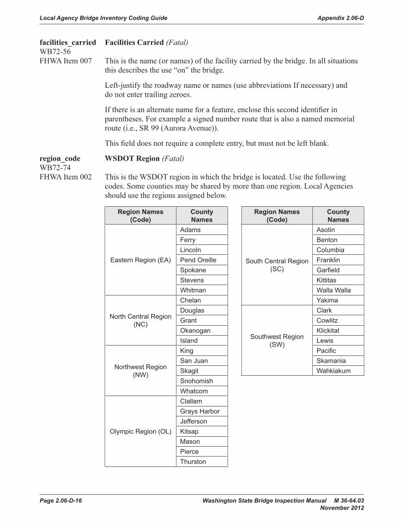
Local Agency Bridge Inventory Coding Guide Appendix 2.06-D
Page 2.06-D-16 Washington State Bridge Inspection Manual M 36-64.03 November 2012
facilities_carried Facilities Carried (Fatal)WB72-56FHWA Item 007 This is the name (or names) of the facility carried by the bridge. In all situations
this describes the use “on” the bridge.
Left-justify the roadway name or names (use abbreviations If necessary) and do not enter trailing zeroes.
If there is an alternate name for a feature, enclose this second identifier in parentheses. For example a signed number route that is also a named memorial route (i.e., SR 99 (Aurora Avenue)).
This field does not require a complete entry, but must not be left blank.
region_code WSDOT Region (Fatal)WB72-74FHWA Item 002 This is the WSDOT region in which the bridge is located. Use the following
codes. Some counties may be shared by more than one region. Local Agencies should use the regions assigned below.
Region Names (Code)
County Names
Region Names (Code)
County Names
Eastern Region (EA)
Adams
South Central Region (SC)
AsotinFerry BentonLincoln ColumbiaPend Oreille FranklinSpokane GarfieldStevens KittitasWhitman Walla Walla
North Central Region (NC)
Chelan YakimaDouglas
Southwest Region (SW)
ClarkGrant CowlitzOkanogan KlickitatIsland Lewis
Northwest Region (NW)
King PacificSan Juan SkamaniaSkagit WahkiakumSnohomishWhatcom
Olympic Region (OL)
ClallamGrays HarborJeffersonKitsapMasonPierceThurston

Appendix 2.06-D Local Agency Bridge Inventory Coding Guide
Washington State Bridge Inspection Manual M 36-64.03 Page 2.06-D-17 November 2012
90
90
5
5
82
82
90
5
Dou
glas
Okano
gan
Chelan
Kittita
s
Yakima
Grant
Ada
ms
Linc
oln
Whitm
an
KingSnoh
omish
Skag
it
Wha
tcom
Pierce
Lewis
Clallam
Klickitat
Je�e
rson
Skam
ania
Cowlitz
Benton
Fran
klin
Walla
Walla
Spok
ane
Ferry
Steven
s
Pen
dOreille
Grays
Harbo
r
Paci�c
Clark
Columbia
Asotin
Wah
kiakum
Thurston
Mason
San
Juan
Kitsap
Gar�e
ld
Nor
thw
est
Nor
thC
entr
al
Oly
mpi
c
Sou
thw
est
Sou
th C
entr
alEas
tern
Spok
ane
Yaki
ma
Ever
ett
Long
view
Vanc
ouve
r
Oly
mpi
aTa
com
aSeat
tleW
enat
chee
Elle
nsbu
rg
Ken
new
ick
Om
ak
Pullm
an
Pt. A
ngel
es
Bel
lingh
am Island

Local Agency Bridge Inventory Coding Guide Appendix 2.06-D
Page 2.06-D-18 Washington State Bridge Inspection Manual M 36-64.03 November 2012
fips_code FIPS Place Code (Required)WB72-76FHWA Item 004 This field identifies the census-designated place in which the bridge is located
using the Federal Information Processing Standards (FIPS 55) code, given in the current version of the Census of Population and Housing – Geographic Identification Code Scheme.
These codes can be located at www.itl.nist.gov/fipspubs/55new/nav-top-fr.htm.
If no code is applicable, enter all zeroes.
leg_dist_code_1 Legislative District Number (1) (Required)WB72-81 This field identifies the first or only State Legislative District in which the bridge
is located (see Section 2.08, Forms).
If the legislative district number is followed by a letter (District 19A, for example), disregard the letter and enter the two-digit number only.
Washington State Legislative District Maps can be found in Chapter 2, Forms.
leg_dist_code_2 Legislative District Number (2) (Required)WB72-83 For bridges which span a State Legislative District dividing line, use this field
to identify the second State Legislative District number.
Use both this and the Legislative District Number (1) field to enter the two separate State Legislative District numbers. If no code is applicable, enter all zeroes.
toll_code Toll (Fatal)WB72-85FHWA Item 020 This code indicates if a toll is required for use of the bridge. One of the following
codes will apply:
1. Toll bridge – a toll must be paid specifically to use the bridge.
2. On toll road – a toll must be paid to use the roadway carried by the bridge.
3. Non-toll bridge – no tolls are paid to use the bridge or the roadway carried by the bridge.
4. On interstate toll segment under secretarial agreement. Bridge functions as a part of the toll segment.
5. Toll bridge is a segment under secretarial agreement. Bridge is separate agreement from highway segment.

Appendix 2.06-D Local Agency Bridge Inventory Coding Guide
Washington State Bridge Inspection Manual M 36-64.03 Page 2.06-D-19 November 2012
custodian_id Custodian (Fatal)WB72-86FHWA Item 021 This code describes the type of agency that has primary responsibility for
maintaining the bridge (may not be the same as the owner). Acceptable values to enter in this field are as follows:
01 State Highway Agency 02 County Highway Agency 03 Town or Township Highway Agency 04 City or Municipal Highway Agency 11 State Park, Forest, or Reservation Agency 12 County Park, Forest, or Reservation Agency 13 City/Other Park, Forest, or Reservation Agency 21 Other State Agencies 24 Other County Agencies 25 Other City or Local Agencies 26 Private (other than Railroad) 27 Railroad 31 State Toll Authority 32 County Toll Authority 33 City or Other Toll Authority 60 Other Federal Agencies (not listed below) 62 Bureau of Indian Affairs 63 Bureau of Fish and Wildlife 64 U.S. Forest Service 66 National Park Service 68 Bureau of Land Management 69 Bureau of Reclamation 70 Corps of Engineers (Civilian) 71 Corps of Engineers (Military) 72 Air Force 73 Navy/Marines 74 Army 75 NASA 76 Metropolitan Washington Airport Services 80 Unknown 91 Canada 92 Idaho 93 Oregon

Local Agency Bridge Inventory Coding Guide Appendix 2.06-D
Page 2.06-D-20 Washington State Bridge Inspection Manual M 36-64.03 November 2012
parallel_structure_ Parallel Structure (Fatal)WB72-88FHWA Item 101 This field contains a code to identify situations in which separate bridges carry
the same inventory route in opposite directions of travel over the same feature. The lateral distance between bridges has no bearing on the coding of this field.
Right and left are determined by facing in the direction of increasing mileposts or, in the absence of milepost markers, by facing north or east.
R To indicate the right-hand bridge of the pair L To indicate the left-hand bridge of the pair N To indicate the bridge is not a parallel bridge
temporary_structure_ Temporary Structure (Required)WB72-89FHWA Item 103 This code indicates If a temporary bridge has been built or temporary measures
have been taken on an existing bridge to maintain a flow of traffic. Temporary bridges or temporary repair measures may be required during the modification or replacement of a bridge found to be deficient.
Any one of the following conditions will require that a code of “T” be entered in this field:• The bridge has been shored up or additional temporary supports have
been installed.• Temporary repairs have been made to keep the bridge open.• A temporary bridge has been built to provide an interim bypass that is not
under the control of a contractor, such as an emergency bailey type bridge.• Other temporary measures have been taken, such as barricaded traffic lanes,
to keep the bridge open to traffic.
If none of these conditions exist, leave the field blank.
Any repaired bridge or replacement bridge expected to remain in service without further project activity (other than maintenance) for a significant period of time shall not be considered temporary. Under such conditions, that bridge, regardless of its type, shall be considered the minimum adequate to remain in place and shall be evaluated accordingly.
If this item is coded T, then all data recorded for the bridge shall be for the condition of the bridge without temporary measures, except for the following items which shall be coded for the temporary bridge:
WB72-93 Structure Open, Posted, or Closed to Traffic WB73-70 Minimum Vertical Clearance Over Bridge Deck WB73-74 Minimum Vertical Clearances Under Bridge WB73-79 Minimum Lateral Under clearance Right WB73-83 Minimum Lateral Under clearance Left WB74-91 Horizontal Clearance Route Direction WB74-95 Horizontal Clearance Reverse Direction WB76-60 Operating Level

Appendix 2.06-D Local Agency Bridge Inventory Coding Guide
Washington State Bridge Inspection Manual M 36-64.03 Page 2.06-D-21 November 2012
critical_facility Critical Facility (Required)WB72-90 FHWA Item 6B No longer coded, leave blank.
median_code Median (Fatal)WB72-91FHWA Item 033 This code indicates If there is a median on the bridge. By definition, a bridge
median can only exist on divided highways.
A divided highway can be identified by the use of traffic control devices separating the route and reverse route directions of travel. Devices such as a concrete barrier, or yellow crosshatching between solid double yellow lines 18 inches or more apart, or others, such that vehicles are restricted to the right-hand lanes unless directed or permitted in the left-hand lanes by a police officer, or other official traffic control devices.
If a structure has been divided into a left and a right bridge so that the median is between the two structures then no median is considered to be on the bridge. Culverts will often have a median similar to the diagram for Code 1.
Use the following diagrams to identify the median device on the bridge.
0 No median (undivided roadway). 1 Open median. 2 Closed median – painted (Traffic lanes are separated only by painted median). 3 Closed median – mountable curb or center island. 4 Closed median – flex or thrie beam guardrail. 5 Closed median – box beam guardrail. 6 Closed median – Concrete (i.e., NJB, Type F barrier). 7 Open median – with safety modifications (i.e., a net has been installed). 9 Other type of median.

Local Agency Bridge Inventory Coding Guide Appendix 2.06-D
Page 2.06-D-22 Washington State Bridge Inspection Manual M 36-64.03 November 2012
Bridge Inventory Coding Guide
Page 2-28 Washington State Bridge Inspection ManualJanuary 2002
Figure WB72 - 91
Code 1
Route DirectionReverse Direction
Median
Code 4
Code 3
Figure WB72-91

Appendix 2.06-D Local Agency Bridge Inventory Coding Guide
Washington State Bridge Inspection Manual M 36-64.03 Page 2.06-D-23 November 2012Washington State Bridge Inspection Manual Page 2-29
January 2002
Bridge Inventory Coding Guide
Figure WB72 - 91
Code 7
Code 5
Code 6
Figure WB72-91

Local Agency Bridge Inventory Coding Guide Appendix 2.06-D
Page 2.06-D-24 Washington State Bridge Inspection Manual M 36-64.03 November 2012
hist_signif Historical Significance (Fatal)WB72-92FHWA Item 037 A bridge may be considered historically significant If it is a particularly
unique example of the history of engineering, the crossing itself is historically significant, the bridge is associated with historical property, or the bridge was involved in events of historical significance.
If the bridge is only on the National Register of Historic Places (NRHP) list, use the numeric code. If the bridge is only on the Historical American Engineering Record (HAER) list, use the alpha code. If the bridge is on both NRHP and HAER lists, use the numeric code. For questions, contact the Office of Archeology and Historic Preservation at 360-586-3065 or www.oahp.wa.gov.
1 or A Bridge is on the NRHP or HAER. 2 or B Bridge is eligible for the NRHP or HAER. 3 or C Bridge is possibly eligible for the NRHP or HAER. (Further
investigation is required before a determination can be made.) 4 Bridge’s historical significance has not been determined at this time.
(This code should be used if the bridge is less than 50 years old.) 5 Bridge has been reviewed by the State Office of Archaeology
and Historic Preservation and is not eligible for the NRHP, HAER. 6 Bridge has been reviewed and a determination has been made that
this bridge has no historical significance.

Appendix 2.06-D Local Agency Bridge Inventory Coding Guide
Washington State Bridge Inspection Manual M 36-64.03 Page 2.06-D-25 November 2012
open_closed Open, Closed, or Posted (Fatal)WB72-93FHWA Item 041 This field provides information about the actual weight capacity status of a
bridge. The field review could show that a structure is posted, but WB76-60 Operating Level may indicate that posting is not required. This is possible and acceptable coding since WB76-60 is based on the operating stress level and the governing agency’s posting procedures may specify posting at some stress level less than the operating rating. One of the following codes shall be used:
A Bridge is open with no restrictions. B Bridge is open. Posting has been recommended but has not been
legally implemented (all signs are not in place). D Bridge is open. It would be posted or closed except that temporary
shoring, etc., has been used to allow for unrestricted traffic flow. If this code is used, WB72-89 shall be coded T.
E Bridge is open, but it is a temporary bridge carrying traffic while the original bridge is being replaced or rehabilitated. If this code is used, WB72-89 shall be coded T.
G Bridge is new and not yet open to traffic. K Bridge is closed to traffic. P Bridge is posted for weight restrictions. R Bridge is posted for other load-capacity restrictions such as speed
or limiting the number of vehicles allowed on the bridge at one time.
program_year Program Year (Required)WB72-94 If the bridge has been included in an approved six-year construction program,
this field contains the year that work is to start on the project, including preliminary engineering.
Work to be performed on the bridge must be major construction or reconstruction. If the bridge is not included in a six-year program, code zeroes in this field.

Local Agency Bridge Inventory Coding Guide Appendix 2.06-D
Page 2.06-D-26 Washington State Bridge Inspection Manual M 36-64.03 November 2012

Appendix 2.06-D Local Agency Bridge Inventory Coding Guide
Washington State Bridge Inspection Manual M 36-64.03 Page 2.06-D-27 November 2012
built_year Year Built (Fatal)WB73-32 FHWA Item 027 This is the year that original construction of the bridge was completed.
If the year the bridge was built is not known, enter an estimate of that date. If the bridge was built during or before the year 1900, enter 1900 in the field.
There are cases where a careful evaluation of the year built and year rebuilt must be made. The first is when an existing bridge has been moved to a new site. The second is when parts of a dismantled bridge from another site are used at a new site. And the third is when parts of the old bridge are used at the same site.
Excluding engineering and safety considerations, an evaluation of the impact on future funding is a factor. The year built and year rebuilt are key fields used to determine If a bridge is eligible for federal funding. Another consideration would be the percentage of used material in relation to new material. The greater the percentage of new material used in the bridge the less need there is of capturing the original date of construction in the inventory.
Since every occasion of these instances will be unique in its application guidance should be sought from your Program Manager when there is question as to the proper year to use.
rebuilt_year Year Rebuilt (Fatal)WB73-36 FHWA Item 106 This is the year in which the last major rehabilitation of the existing bridge
was completed.
Record and code the year of most recent reconstruction of the structure. Code all four digits of the latest year in which reconstruction of the structure was completed. If there has been no reconstruction, code 0.
For a bridge to be defined as rebuilt, the type of work performed, whether or not it meets current minimum standards must have been eligible for funding under any of the federal aid funding categories. The eligibility criteria would apply to the work performed regardless of whether all state or local funds or federal aid funds were used.
Some types of eligible work not to be considered as rebuilt are listed:
• Safety feature replacement or upgrading (for example, bridge rail, approach guardrail, or impact attenuators).
• Painting of structural steel.
• Overlay of bridge deck as part of a larger highway surfacing project (for example, overlay carried across bridge deck for surface uniformity without additional bridge work).
• Utility work.
• Emergency repair to restore structural integrity to the previous status following an accident.

Local Agency Bridge Inventory Coding Guide Appendix 2.06-D
Page 2.06-D-28 Washington State Bridge Inspection Manual M 36-64.03 November 2012
• Retrofitting to correct a deficiency which does not substantially alter physical geometry or increase the load-carrying capacity.
• Work performed to keep a bridge operational while plans for complete rehabilitation or replacement are under preparation (for example, adding a substructure element or extra girder).
Example Code
Rebuild completed 1970 1970 Bridge has NOT been Rebuilt 0
structure_length Bridge Length (Fatal)WB73-40FHWA Item 49 This is the measurement for the length of roadway supported by the bridge.
This measurement is taken along the center of the roadway from the back of the backwall of each abutment or from the back of paving notch (seat) to paving notch (seat). Culvert lengths are measured along the centerline of the roadway from inside face to inside face of the exterior walls, or from spring line to spring line, regardless of depth below grade. When the culvert is not perpendicular to the roadway, the centerline length must be calculated. Code this measurement to the nearest foot.
The bridge length entered in this field is considered the length when determining eligibility for federal funding, except when the bridge length is near 20 feet. If that is the case, the length of the bridge as entered in NBIS Length will be used. See Figure WB73-40A and Figure WB73-40B.
nbi_length NBIS Length (Fatal, If WB73-40 is between 20 and 23 feet)WB73-46FHWA Item 112 The NBIS bridge length is a measurement along the center of the roadway
between undercopings of abutments, spring lines of arches, or the extreme ends of openings for multiple boxes.
This measurement is coded to the nearest tenth of a foot and may be different from the measurement entered in Bridge Length.
If the measurement as entered in Bridge Length is between 20 and 23 feet, a measurement of the NBIS length shall be coded in this field.
If the measurement as entered in Structure Length is greater than 23 feet, this field shall be left blank. See Figure WB73-40A and Figure WB73-40B.
max_span_length Maximum Span Length (Fatal)WB73-48FHWA Item 048 This is the number of feet which the bridge spans at its maximum opening.
This length is measured along the centerline of the bridge. The span length is measured either as the center-to-center distance between bearings or the clear distance between piers, bents, or abutments. The preferred measurement to enter is the center-to-center distance between bearings. The span may be either a main span or approach span. See Figure WB73-40A and Figure WB73-40B.

Appendix 2.06-D Local Agency Bridge Inventory Coding Guide
Washington State Bridge Inspection Manual M 36-64.03 Page 2.06-D-29 November 2012
Washington State Bridge Inspection Manual Page 2-35January 2002
Bridge Inventory Coding Guide
Figure WB73 - 40A
A & B & C
A
C
B
A = Structure Length (WB73-40)
B = NBIS Length (WB 73-46)C = Maximum Span Length (WB73-48)
For a culvert, it doesn't matter if the roadway is on the slabor on ballast, "A" will remain unchanged.
A & B
C
Figure WB73-40A

Local Agency Bridge Inventory Coding Guide Appendix 2.06-D
Page 2.06-D-30 Washington State Bridge Inspection Manual M 36-64.03 November 2012
C
30 ° SKEW ANGLE
A & B
A = Structure length ( WSBIS Item 340 )
B = NBIS Length ( WSBIS Item 346 )
C = Maximum span length ( WSBIS Item 348 )
D = the distance between consecutive pipes , which must be = or < the diameter of the smallest pipe in the series .
Roadway ¢
Opening Distance = 18 ' = 5 ' + 1 ' + 7 ' + 1 ' + 4 '
A ( normal to the pipes ) = cos ( 30 ) = . 867 = 20 . 76 ' ( Code 21 ' ) 18 ' 18 '
C = cos ( 30 ) = 8 . 08 ' ( code 8 ' ) 7
A
B & C
For a structure with ballast ( where the ballast is > A / 2 ) such that the live load is not transferred into the deck , " A " will be inside the face of the exterior walls. .
Figure WB73-40B

Appendix 2.06-D Local Agency Bridge Inventory Coding Guide
Washington State Bridge Inspection Manual M 36-64.03 Page 2.06-D-31 November 2012
lane_on Lanes On (Fatal)WB73-52FHWA Item 028A The number of lanes of motor vehicle traffic carried by the bridge must be
entered in this field. It includes all traffic lanes which are striped or otherwise marked as full-width lanes for the entire length of the ridge.
Include any full-width merge lanes or ramp lanes carried on the bridge. The number of traffic lanes is independent of the direction in which these lanes carry traffic. That is, a one-lane bridge which carries traffic in two directions is considered to have only one lane on the bridge.
It should be noted here for purposes of the Deck Geometry Evaluation any one-way bridge (excluding ramps, WB74-34 coded 7) which has a curb-to-curb width 16 feet or greater shall be evaluated as two lanes. Also, If the curb-to-curb is less than 16 feet and the bridge carries two way traffic, then WB73-52 is coded Ø1 and WB74-90 is coded 5. For information to code a half bridge, see Appendix 2.07A.
lane_under Lanes Under (Fatal)WB73-54FHWA Item 028B This field contains the number of lanes of motor vehicle traffic carried by the
highway or highways which pass underneath the bridge.
If the bridge carries highway traffic (WB74-32 is coded 1, regardless of ownership and/or maintenance responsibility), it is the total number of lanes of all inventory routes passing underneath.
If the route being inventoried is under the bridge (WB74-32 coded 2 or A-Z), this is the number of lanes of the inventoried route only.
There may be a separate record of some or all of the routes located under the bridge (see WB74-32 for routes requiring a record in the NBI).

Local Agency Bridge Inventory Coding Guide Appendix 2.06-D
Page 2.06-D-32 Washington State Bridge Inspection Manual M 36-64.03 November 2012
curb_to_curb_width Curb-to-Curb Width (Fatal)WB73-56FHWA Item 051 The curb-to-curb width is the measurement, in feet, of the most restrictive width
of the structure from curb-to-curb (or inside face of rail to inside face of rail if no curb). This is a Fatal Field.
This measurement is recorded to the nearest tenth of a foot. For structures that carry lanes of traffic separated by a median barrier, the curb-to-curb width is the sum of the most restrictive minimum widths of each roadway carried on the structure. The widths of any open medians, raised or non-mountable medians, barrier-protected horse or bicycle lanes, or flared ramps should be excluded from this measurement.
When the roadway runs directly on the top slab or wearing surface of a culvert (such as a reinforced concrete box without fill), the actual roadway width from curb-to-curb or from rail-to-rail is entered in this field. This is also the case If the fill is minimal and the culvert headwalls reduce the roadway width. When there are no lateral restrictions such as curbs or rails the actual usable roadway width is recorded as the curb-to-curb measurement.
When the roadway is carried on sufficient fill covering a pipe or box culvert so that the load is not transferred into the structure, and when headwalls or parapets do not affect the flow of traffic, a value of Ø should be entered in this field. The filled section over the culvert simply maintains the roadway cross-section, the structure itself is considered to have no deck and thus no curb-to-curb width.
It should be noted, however, that for purposes of Sufficiency Rating calculations the program will default to a curb-to-curb width of 36´ for the S2, D, and E calculations.
For the correct coding of a Side Hill Viaduct (Half Bridge), see Appendix 2.07A.
Bridge Inventory Coding Guide
Page 2-38 Washington State Bridge Inspection ManualJanuary 2002
curb_to_curb_width Curb-to-Curb Width (Fatal)WB73 - 56FHWA Item 051 The curb-to-curb width is the measurement, in feet, of the most
restrictive width of the structure from curb-to-curb (or inside face ofrail to inside face of rail if no curb). This is a Fatal Field.
This measurement is recorded to the nearest tenth of a foot. Forstructures that carry lanes of traffic separated by a median barrier, thecurb-to-curb width is the sum of the most restrictive minimum widthsof each roadway carried on the structure. The widths of any openmedians, raised or non-mountable medians, barrier-protected horseor bicycle lanes, or flared ramps should be excluded from thismeasurement.
When the roadway runs directly on the top slab or wearing surface ofa culvert (such as a reinforced concrete box without fill), the actualroadway width from curb-to-curb or from rail-to-rail is entered inthis field. This is also the case if the fill is minimal and the culvertheadwalls reduce the roadway width. When there are no lateralrestrictions such as curbs or rails the actual useable roadway widthis recorded as the curb-to-curb measurement.
When the roadway is carried on sufficient fill covering a pipe or boxculvert so that the load is not transferred into the structure, and whenheadwalls or parapets do not affect the flow of traffic, a value of /0 /0 /0 /0should be entered in this field. The filled section over the culvertsimply maintains the roadway cross-section, the structure itself isconsidered to have no deck and thus no curb-to-curb width.
It should be noted, however, that for purposes of Sufficiency Ratingcalculations the program will default to a curb-to-curb width of 36′for the S2, D, and E calculations.
For the correct coding of a Side Hill Viaduct (Half Bridge), seeAppendix 2.07A
Curb-to-Curb Roadway WidthCurb-to-Curb Roadway WidthFigure WB73-56

Appendix 2.06-D Local Agency Bridge Inventory Coding Guide
Washington State Bridge Inspection Manual M 36-64.03 Page 2.06-D-33 November 2012
Washington State Bridge Inspection Manual Page 2-39January 2002
Bridge Inventory Coding Guide
Curb-to-Curb Roadway WidthFigure WB73 - 56
Non-mountablemedian andcurb
2 = 2a + 2b + 2c1 = 1a + 1b
WB73-56 (1) Bridge Roadway Width, Curb-to-CurbWB73-60 (2) Deck Width, Out-to-OutWB73-64 (3) Curb or Sidewalk Width
1a 1b 1c 3
2
1 = 1a + 1b + 1c
2
Mountablemedian
1 = 1a + 1b + 1c
1c
2a
1a
2c
1b1a3
varies
2b
1b
Non-mountablemedian andcurb
44’ 50.2’ 12.7 3
Out-To-Out
Curb-to-Curb Width = 44’+50.2’+12.7’ = 106.9’
Curb-to-Curb Roadway WidthFigure WB73-56

Local Agency Bridge Inventory Coding Guide Appendix 2.06-D
Page 2.06-D-34 Washington State Bridge Inspection Manual M 36-64.03 November 2012
out_to_out_width Out-to-Out Deck Width (Fatal)WB73-60FHWA Item 052 This field contains the measurement of the most representative out-to-out width
on the bridge. This measurement should be taken normal to centerline from the outside edges of each side of the deck and coded to the nearest tenth of a foot. The widths of any open medians, or flared ramps should be excluded from this measurement. For through structures, the out-to-out width is a measurement of the lateral clearance between superstructure members. See Figures WB73-56 and WB73-60.
When the roadway runs directly on the culvert (as described in Curb-to-Curb Width), the width of the culvert itself, from outside edge to outside edge, should be entered in this field. When the roadway is carried on fill over a buried culvert (also described in Curb-to-Curb Width), a value of zero should be entered.
See Appendix 2.07-A for Side Hill Viaduct (Half Bridge) coding.

Appendix 2.06-D Local Agency Bridge Inventory Coding Guide
Washington State Bridge Inspection Manual M 36-64.03 Page 2.06-D-35 November 2012Washington State Bridge Inspection Manual Page 2-41
January 2002
Bridge Inventory Coding Guide
Figure WB73 - 60
E
C
A
B
D
A = Curb-to-Curb width (WB73 – 56)
B = Out-to-Out Deck width (WB73 – 60)
C = Sidewalks and Curb – Left (WB73 – 64)
D = Sidewalks and Curb – Right (WB73 – 67)
E = Minimum Vertical Clearance Over Bridge Deck (WB73 – 70)
HORIZONTAL / VERTICAL MEASUREMENTS
(Looking Ahead on Mileposts)
Figure WB73-60

Local Agency Bridge Inventory Coding Guide Appendix 2.06-D
Page 2.06-D-36 Washington State Bridge Inspection Manual M 36-64.03 November 2012
sdwk_curb_left Sidewalk/Curb Width, Left (Required)WB73-64FHWA Item 050A The combined usable width of the left-hand sidewalk and curb on the bridge is
entered in this field. The left-hand side of the bridge is determined by facing in the direction of increasing mileposts. If no mileposts are in use, left is determined by facing north or east. See Figure WB73-64.
This measurement is coded to the nearest tenth of a foot.
If the bridge has no functional sidewalks and/or curbs, code zeroes in this field. If the bridge has concrete barriers for rails and no sidewalks, also code zeroes.
Bridge Inventory Coding Guide
Page 2-42 Washington State Bridge Inspection ManualJanuary 2002
sdwk_curb_left Sidewalk/Curb Width, Left (Required)WB73 - 64FHWA Item 050A The combined useable width of the left-hand sidewalk and curb on
the bridge is entered in this field. The left-hand side of the bridgeis determined by facing in the direction of increasing mileposts.If no mileposts are in use, left is determined by facing north or east.See Figure WB73 - 64.
This measurement is coded to the nearest tenth of a foot.
If the bridge has no functional sidewalks and/or curbs, code zeroes inthis field. If the bridge has concrete barriers for rails and no sidewalks,also code zeroes.
Figure WB73 - 64
sdwk_curb_right Sidewalk/Curb Width, Right (Required)WB73 - 67FHWA Item 050B The combined useable width of the right-hand sidewalk and curb on
the bridge is entered in this field. The right-hand side of the bridge isdetermined by facing in the direction of increasing mileposts. If nomileposts are in use, right is determined by facing north or east.
This measurement is coded to the nearest tenth of a foot.
If the bridge has no functional sidewalks and/or curbs, code zeroes inthis field. If the bridge has concrete barriers for rails and no sidewalks,also code zeroes.
Curb orsidewalk
No longerusable as curb
or sidewalk
Before Rail Retrofit After Rail Retrofit.Code curb/sidewalkLeft of Right zero
Figure WB73-64
sdwk_curb_right Sidewalk/Curb Width, Right (Required)WB73-67FHWA Item 050B The combined usable width of the right-hand sidewalk and curb on the bridge
is entered in this field. The right-hand side of the bridge is determined by facing in the direction of increasing mileposts. If no mileposts are in use, right is determined by facing north or east.
This measurement is coded to the nearest tenth of a foot.
If the bridge has no functional sidewalks and/or curbs, code zeroes in this field. If the bridge has concrete barriers for rails and no sidewalks, also code zeroes.

Appendix 2.06-D Local Agency Bridge Inventory Coding Guide
Washington State Bridge Inspection Manual M 36-64.03 Page 2.06-D-37 November 2012
min_vert_deck Minimum Vertical Clearance Over Deck (Required)WB73-70FHWA Item 053 The minimum vertical clearance over the bridge deck is entered in this field.
This measurement is coded to the nearest lesser inch and should be taken from the top of the traffic lane or shoulder to a point where the clearance is the most restrictive to include bridge mounted elements. The foot (′) and inch (″) symbols are already marked in the field. See Figure WB73-60.
If there is no restriction, code 9999 in this field. If the minimum restriction is a distance greater than 100 feet, code 9912.
min_vert_under Minimum Vertical Clearance Under Bridge WB73-74 (Required)FHWA Item 054B This field contains the minimum vertical clearance measured under the bridge.
This is the minimum vertical clearance from the roadway (travel lanes only) or railroad track beneath the bridge to the underside of the superstructure. See Figure WB73-74.
The value is coded to the nearest lesser inch. The posted clearance is typically less than the measured value. The measured value should be reported in this field. WSDOT typically posts bridges with clearance less than 15′-3″.
If the bridge does not cross a highway or a railroad, zeroes should be entered. If the bridge crosses both a highway and a railroad, code the most critical dimension and note why it is the one recorded in the inspection report. See Figure WB73-78.

Local Agency Bridge Inventory Coding Guide Appendix 2.06-D
Page 2.06-D-38 Washington State Bridge Inspection Manual M 36-64.03 November 2012
Bridge Inventory Coding Guide
Page 2-44 Washington State Bridge Inspection ManualJanuary 2002
Vertical ClearancesFigures WB73 - 74 and WB73 - 78
24'-9
"
16'-0
"
16'-2
"
16'
-2"
16'-0
"
16'-
1"15
'-5"
15
'-6"
15'-2
"
15'-3
"15
'-7"
1
5'-7"
15'-5
"
15'-
5"14'-10"
14'
-11"
24'-9
"
24'-1
0"25
'-2"
2
5'-3"
16'-3
"
16'
-3"
Shld
.
Mai
nlin
e
Mai
nlin
e
Acce
l. La
ne
Shld
.
Shld
.
Shld
.
Shld
.
Mai
nlin
e
Mai
nlin
e
Acce
l. La
ne
RR T
rack
RR T
rack
24'-1
1"
2
5'-00
"
Shld
.
25'-2
"
25'-
3"
5' 13' 12' 12' 4' 4' 12' 12' 13' 5' 6' 8' 5' 8' 6'
16'-3
"
16'-2
"
15'-5
"
15'-2
"
15'-7
"
15'-5
"
14'-10"
25'-2
"25
'-2"
24'-1
1"
Code the most Restrictive Clearances:WB73 – 74 would be coded 1410WB73 – 78 would be coded H
Figure WB73-74 and WB73-78
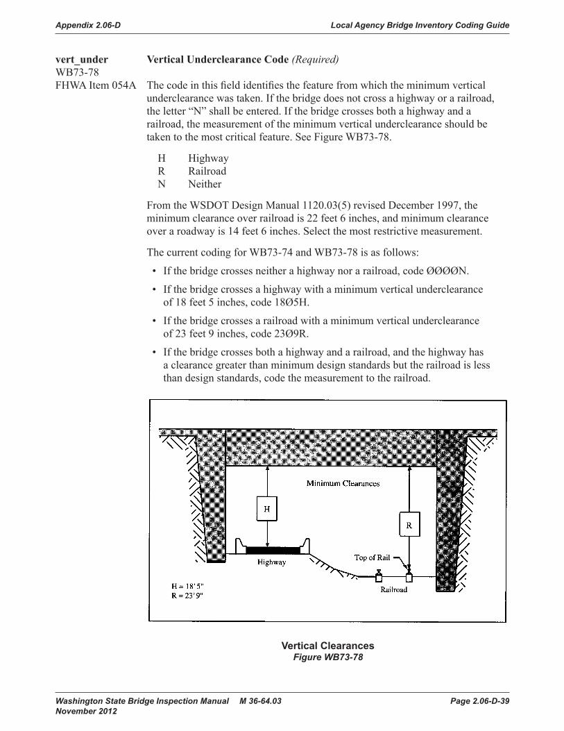
Appendix 2.06-D Local Agency Bridge Inventory Coding Guide
Washington State Bridge Inspection Manual M 36-64.03 Page 2.06-D-39 November 2012
vert_under Vertical Underclearance Code (Required)WB73-78FHWA Item 054A The code in this field identifies the feature from which the minimum vertical
underclearance was taken. If the bridge does not cross a highway or a railroad, the letter “N” shall be entered. If the bridge crosses both a highway and a railroad, the measurement of the minimum vertical underclearance should be taken to the most critical feature. See Figure WB73-78.
H Highway R Railroad N Neither
From the WSDOT Design Manual 1120.03(5) revised December 1997, the minimum clearance over railroad is 22 feet 6 inches, and minimum clearance over a roadway is 14 feet 6 inches. Select the most restrictive measurement.
The current coding for WB73-74 and WB73-78 is as follows:
• If the bridge crosses neither a highway nor a railroad, code ØØØØN.
• If the bridge crosses a highway with a minimum vertical underclearance of 18 feet 5 inches, code 18Ø5H.
• If the bridge crosses a railroad with a minimum vertical underclearance of 23 feet 9 inches, code 23Ø9R.
• If the bridge crosses both a highway and a railroad, and the highway has a clearance greater than minimum design standards but the railroad is less than design standards, code the measurement to the railroad.
Washington State Bridge Inspection Manual Page 2-45January 2002
Bridge Inventory Coding Guide
vert_under Vertical Underclearance Code (Required)WB73 - 78FHWA Item 054A The code in this field identifies the feature from which the minimum
vertical underclearance was taken. If the bridge does not cross ahighway or a railroad, the letter “N” shall be entered. If the bridgecrosses both a highway and a railroad, the measurement of theminimum vertical underclearance should be taken to the most criticalfeature. See Figure WB73 - 78.
H HighwayR RailroadN Neither
From the WSDOT Design Manual 1120.03(5) revised December 1997,the minimum clearance over railroad is 22 feet 6 inches, and minimumclearance over a roadway is 14 feet 6 inches. Select the most restrictivemeasurement.
The current coding for WB73 - 74 and WB73 - 78 is as follows:
• If the bridge crosses neither a highway nor a railroad, code /0 /0 /0 /0N.
• If the bridge crosses a highway with a minimum verticalunderclearance of 18 feet 5 inches, code 18 /05H.
• If the bridge crosses a railroad with a minimum verticalunderclearance of 23 feet 9 inches, code 23/09R.
• If the bridge crosses both a highway and a railroad, and thehighway has a clearance greater than minimum design standardsbut the railroad is less than design standards, code themeasurement to the railroad.
Vertical ClearancesFigure WB73 - 78Vertical ClearancesFigure WB73-78

Local Agency Bridge Inventory Coding Guide Appendix 2.06-D
Page 2.06-D-40 Washington State Bridge Inspection Manual M 36-64.03 November 2012
lateral_route_right Minimum Lateral Underclearance Right (Required)WB73-79FHWA Item 055B Using a three-digit number and a one-digit code (WB73-82), record the minimum
lateral underclearance on the right to the nearest tenth of a foot (with an assumed decimal point). When both a railroad and highway are under the bridge, code the most critical dimension. This measurement is determined while facing the direction the traffic flows.
The lateral clearance should be measured from the right edge of the roadway (excluding shoulders) or from the centerline (between rails) of the right hand track of a railroad to the nearest substructure unit (pier, abutment, etc.), to a rigid barrier (concrete bridge rail, etc.), or to the toe of a slope steeper than 3:1. The clearance measurements to be recorded will be the minimum after measuring the clearance in both directions of travel. In the case of a divided highway, this would mean the outside clearances of both roadways should be measured and the smaller distance recorded and coded (see Figures WB73-79 through WB73-83).
If two related features are below the bridge, measure both and record the lesser of the two. An explanation should be written on the inspection form as to what was recorded. When the clearance is 100 feet or greater, code 999.
If the feature beneath the bridge is not a railroad or highway, code ØØØN to indicate not applicable.
The presence of ramps and acceleration or turning lanes is not considered in this item; therefore, the minimum lateral clearance on the right should be measured from the right edge of the through roadway.
Examples Code
Railroad 6.22 feet centerline to pier 062
Highway 6.16 feet edge of pavement to pier 062
Creek beneath bridge 000
lateral_route Lateral Underclearance Code (Required)WB73-82FHWA Item 055A This code identifies the type of reference feature from which the minimum lateral
underclearance measurement on the right was taken. See Figures WB73-79 through WB73-83.
H Highway beneath bridge. R Railroad beneath bridge. N Feature beneath the bridge is neither a highway nor a railroad.

Appendix 2.06-D Local Agency Bridge Inventory Coding Guide
Washington State Bridge Inspection Manual M 36-64.03 Page 2.06-D-41 November 2012
lateral_route_left Minimum Lateral Underclearance Route Left WB73-83 (Required)FHWA Item 056 Code only for divided highways, one way streets, and ramps. This is not
applicable to railroads or two-way roads with closed medians. Using a three-digit number, record and code the minimum lateral underclearance on the left (median side for divided highways) to the nearest tenth of a foot (with an assumed decimal point). The lateral clearance should be measured from the left edge of the roadway (excluding shoulders) to the nearest substructure unit, to a rigid barrier, or to the toe of slope steeper than 1 to 3. Refer to Figures WB73-79 through WB73-83.
In the case of a divided highway, the median side clearances of both roadways should be measured and the smaller distance recorded and coded. If there is no obstruction in the median area, a notation of “open” should be recorded and 999 should be coded. For clearances greater than 100 feet, code 998. Code ØØØ to indicate not applicable.
Code Description
000 Not applicable. 998 Clearance equal to 99.8 feet or greater. 999 Divided highway with no obstructions.

Local Agency Bridge Inventory Coding Guide Appendix 2.06-D
Page 2.06-D-42 Washington State Bridge Inspection Manual M 36-64.03 November 2012
Bridge Inventory Coding Guide
Page 2-48 Washington State Bridge Inspection ManualJanuary 2002
Figure WB73 - 79 through 83
15.1'
UNDIVIDED HIGHWAY
RAILROAD
CL
20.4'30.5'
For Minimum Lateral Underclearance Left, Code 000
2:1
2:1
For Minimum Lateral Underclearance Right, Code 20.4RFor Minimum Lateral Underclearance Left, Code 000
20.1'
KMA
For Minimum Lateral Underclearance Right, Code 15.1H
Figures WB73-79 through WB73-83

Appendix 2.06-D Local Agency Bridge Inventory Coding Guide
Washington State Bridge Inspection Manual M 36-64.03 Page 2.06-D-43 November 2012
Washington State Bridge Inspection Manual Page 2-49January 2002
Bridge Inventory Coding Guide
Figure WB73 - 79 through 83
DIVIDED HGHWAY
15.1' 20.1'
For Minimum Lateral Underclearance Right, Code 20.4HFor Minimum Lateral Underclearance Left, Code 18.2
For Minimum Lateral Underclearance Right, Code 20.1HFor Minimum Lateral Underclearance Left, Code 15.1
ONE - WAY ROADWAY
20.4'19.3'21.1' 18.2'
KMA
KMA
Figures WB73-79 through WB73-83

Local Agency Bridge Inventory Coding Guide Appendix 2.06-D
Page 2.06-D-44 Washington State Bridge Inspection Manual M 36-64.03 November 2012
nav_control_code Navigation Control Code (Fatal)WB73-86FHWA Item 038 This field indicates whether or not a navigation control (a bridge permit
for navigation as issued by the United States Coast Guard) is required.
0 No navigation control on waterway (bridge permit does not exist). 1 Yes, navigation control on waterway (a bridge permit exists). N Not applicable (bridge does not cross a waterway).
nav_vert_clrnc Navigation Vertical Clearance (Required)WB73-87FHWA Item 039 This field contains the minimum vertical clearance allowable for navigational
purposes. If the Navigation Control code has been coded 1, this field will show the number of feet (to the nearest foot rounded down) of minimum vertical clearance imposed at the site. This is not a field measurement but is the number of feet as measured above a datum point specified on the navigation permit.
In the case of a swing or bascule bridge, the clearance should be measured with the bridge in the closed position. In the case of a vertical lift bridge, the clearance should be measured with the bridge in the raised or open position.
If the Navigation Control code has been coded Ø or N, enter zeros in this field to indicate there is no navigational clearance.
nav_horiz_clrnc Navigation Horizontal Clearance (Required)WB73-90FHWA Item 040 This field contains the minimum horizontal clearance allowable for navigational
purposes. If the Navigation Control code has been coded 1, this field will show the number of feet (to the nearest foot rounded down) of minimum horizontal clearance between fenders (If any), or the minimum clear distance between piers or bents. This is the measurement shown on the navigation permit and may be less than the actual clearance distance measured on site.
If the Navigation Control code has been coded Ø or N, enter zeros in this field to indicate there is no navigational clearance.
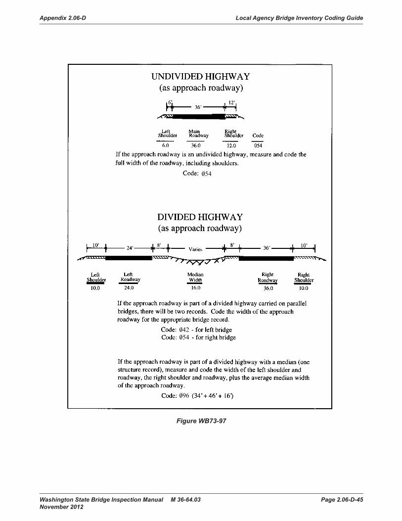
Appendix 2.06-D Local Agency Bridge Inventory Coding Guide
Washington State Bridge Inspection Manual M 36-64.03 Page 2.06-D-45 November 2012
Bridge Inventory Coding Guide
Page 2-52 Washington State Bridge Inspection ManualJanuary 2002
Figure WB73 - 97
/042
/096
/054
/054
Figure WB73-97

Local Agency Bridge Inventory Coding Guide Appendix 2.06-D
Page 2.06-D-46 Washington State Bridge Inspection Manual M 36-64.03 November 2012
vert_lift_min_clrnc Vertical Lift Minimum Navigation Clearance (Required)WB73-94FHWA Item 116 For vertical lift bridges, this value indicates the minimum vertical clearance for
navigational purposes when the bridge is in the closed position (that is, when the bridge allows vehicular traffic to cross).
If the Navigation Control code has been coded 1 and the bridge is a vertical lift bridge, this field will show the number of feet (to the nearest foot rounded down) of minimum vertical clearance imposed at the site. This is the number of feet as measured above a datum point specified on a navigation permit.
If the Navigation Control code has been coded 1, but the bridge is not a vertical lift bridge, leave the field blank.
aprch_width Approach Roadway Width (Fatal)WB73-97FHWA Item 032 This is the normal width to the nearest foot of the roadway approaching the
bridge. This measurement should include the width of shoulders If the shoulders have been constructed so that they are maintained flush with the adjacent traffic lane and are structurally consistent with these traffic lanes.
This measurement should disregard localized widening. Grass or dirt adjacent to the traffic lanes but not within the maintained roadway should not be considered part of the approach roadway for this item.
For bridges with closed medians, the normal width of the median between the roadways approaching the bridge should not be included in this measurement. Where there is a variation between the approach widths at either end of the bridge, code the narrowest of the approach widths in this field. See Figure WB73-97.

Appendix 2.06-D Local Agency Bridge Inventory Coding Guide
Washington State Bridge Inspection Manual M 36-64.03 Page 2.06-D-47 November 2012
nominal_skew_angle Skew Angle (Fatal)WB73-100FHWA Item 034 The skew angle is a measurement of the angle of intersection between the
centerline of a pier and a line drawn perpendicular to the roadway centerline. This angle is coded to the nearest whole degree. See Figure WB73-100.
If the bridge is not skewed, enter 00 in this field. If the skew angle varies from pier to pier, enter the average skew angle, provided it is a representative figure. If it is not, code 99 in this field to indicate that a major variation exists in the skew angles measured from the separate piers supporting the bridge.
Washington State Bridge Inspection Manual Page 2-53January 2002
Bridge Inventory Coding Guide
nominal_skew_angle Skew Angle (Fatal)WB73 - 100FHWA Item 034 The skew angle is a measurement of the angle of intersection between
the centerline of a pier and a line drawn perpendicular to the roadwaycenterline. This angle is coded to the nearest whole degree. SeeFigure WB73 - 100.
If the bridge is not skewed, enter /0 /0 in this field. If the skew anglevaries from pier to pier, enter the average skew angle, provided it is arepresentative figure. If it is not, code 99 in this field to indicate that amajor variation exists in the skew angles measured from the separatepiers supporting the bridge.
flared_flag Flared Flag (Fatal)WB73 - 102FHWA Item 035 This code indicates whether or not the width of the bridge varies (or
flares). Although there may be other causes, generally such varianceis the result of ramps converging or diverging from the structure’sthrough lanes. Minor widening at the four corners of the bridge(i.e., for aesthetic reasons) is not to be considered a flare.
N No, bridge does not flare.Y Yes, bridge flares.
Figure WB73 - 100
SkewAngle
Figure WB73-100
flared_flag Flared Flag (Fatal)WB73-102FHWA Item 035 This code indicates whether or not the width of the bridge varies (or flares).
Although there may be other causes, generally such variance is the result of ramps converging or diverging from the structure’s through lanes. Minor widening at the four corners of the bridge (i.e., for aesthetic reasons) is not to be considered a flare.
N No, bridge does not flare. Y Yes, bridge flares.

Local Agency Bridge Inventory Coding Guide Appendix 2.06-D
Page 2.06-D-48 Washington State Bridge Inspection Manual M 36-64.03 November 2012

Appendix 2.06-D Local Agency Bridge Inventory Coding Guide
Washington State Bridge Inspection Manual M 36-64.03 Page 2.06-D-49 November 2012
on_under_code Inventory Route On /Under (Fatal)WB74-32FHWA Item 005A This field identifies whether the route being inventoried is carried on or is
under the bridge. It cannot be overemphasized that all route-oriented data must agree in the coding as to whether the route being inventoried is “on” or “under” the bridge.
For all records, there are data elements related to the structure and data elements related to the inventory route. The data elements related to the structure (structure data) will not change whether you are coding for the route on the bridge or for the route under the bridge. However, the data elements related to the inventory route (crossing data) are related to the specific route being inventoried.
These two data element types are maintained in two separate tables in the database and are related to each other by the Structure Identifier and a Crossing Key. The Crossing Key is created from the owner code, route number, and mile post to create a unique addressing code for each crossing. Therefore, each bridge will have only one structure record but may have multiple crossing records.
In order for the computer to keep multiple crossings related to their structure elements, it uses a flag known as the Main listing and Secondary listing flag. All structure records are related to the Main listing. The first or only crossing record for a route is also related to the Main listing. The same is true for under routes where no “on” record is coded, such as a tunnel.
However, where a record for a route is coded “on” a bridge and another record(s) will be coded for a route(s) under the same bridge, there must be a Secondary listing(s) created. This Inventory Coding Form was not designed to report Secondary listings. Regardless of whether the code in this field is 1 or 2, this report always displays the Main listing information.
For Secondary listings, another form must be used. If your agency has a bridge over a federal aid route that fits into this category, contact the Bridge Engineer for Local Agencies for the proper procedures.
For entering the code in this field for the Main listing, use one of the following codes:
Code Description
1 Route being inventoried is On the bridge.
2 Route being inventoried is Under the bridge. This would be the code for a single route under the bridge, for tunnels, pedestrian, and railroad undercrossings or even a building.
A-Z Multiple routes go Under the bridge. The code A will be used for the most important of the multiple routes on separate roadways under the bridge. Z will be for the 26th route under the bridge. The level of importance is determined by STRAHNET designation and the highway class.

Local Agency Bridge Inventory Coding Guide Appendix 2.06-D
Page 2.06-D-50 Washington State Bridge Inspection Manual M 36-64.03 November 2012
If the code entered here is 2 or A-Z, only the following fields need to be entered:
Field Name WSBIS Code FHWA No.Location WB71-56 009Latitude WB71-88 016Longitude WB71-96 017Features Intersected WB72-32 006AFacilities Carried WB72-56 007FIPS Place Code WB72-76 004Toll WB72-85 020Parallel Structure WB72-88 101Temporary Structure WB72-89 103Critical WB72-90 06BYear Built WB73-32 027Bridge Length WB73-40 049NBIS Length WB73-46 112Maximum Span Length WB73-48 048Lanes On WB73-52 028ALanes Under WB73-54 028BMin Vertical Clearance Under Bridge WB73-74 054BVertical Underclearance Code WB73-78 054BMinimum Lateral Underclearance Right WB73-79 055BLateral Underclearance Code WB73-82 055AMinimum Lateral Underclearance Route Left WB73-83 056On/Under WB74-32 005AHighway Class WB74-33 005BService Level WB74-34 005CRoute Number WB74-35 005DMile Post WB74-40 01}ADT On Inventory Route WB74-45 029Truck ADT PCT WB74-51 109ADT Year WB74-53 030National Highway System WB74-83 104Base Highway Network WB74-84 012Strahnet WB74-85 100Fed Functional Class WB74-87 026National Truck Net WB74-89 110Lane Use Direction WB74-90 102Horizontal Clearance Route Dir WB74-91 047Horizontal Clearance Reverse Dir WB74-95 047Max Vertical Clearance Route Dir WB74-99 110Detour Length WB74-103 119Main Span Material WB75-32 043AMain Span Design WB75-33 043BService On WB75-44 042AService Under WB75-45 042B
Tunnels shall be coded as an “under” record only; that is, they shall not be coded as a bridge carrying highway traffic.

Appendix 2.06-D Local Agency Bridge Inventory Coding Guide
Washington State Bridge Inspection Manual M 36-64.03 Page 2.06-D-51 November 2012
hwy_class Inventory Route Highway Class (Fatal)WB74-33FHWA Item 005B This code identifies what type of highway the inventoried route is on using
the following:
1 Interstate highway 2 U.S. numbered highway 3 State highway 4 County road 5 City street 6 Federal lands road 7 State lands road 8 Other (include toll roads not otherwise identified.)
When two or more routes are concurrent, the highest class of route will be used. The hierarchy is in the order listed above.
serv_level_ Inventory Route Service Level (Fatal)WB74-34FHWA Item 005C This code describes the designated level of service provided by the
inventoried route:
1 Mainline (most local agency bridges) 2 Alternate 3 Bypass 4 Spur 6 Business 7 Ramp or “Y” 8 Service and/or unclassified Frontage Road Ø None of the above
route Route (Fatal)WB74-35FHWA Item 005D The number of the inventory route on (or under) the bridge must be entered in
this field. County agencies should enter the County Road Log Number as the inventory route number. City agencies should enter a route number If one has been assigned. If not, the city can enter any unique number in this field; however, rather than arbitrarily assigning a random number, it is recommended that city agencies enter their city number code. This will ensure that two cities within the same county will not enter an identical route number.
Example:
If the bridge is located on highway 14, code 00014. If the bridge is located in Sprague, code 01225.

Local Agency Bridge Inventory Coding Guide Appendix 2.06-D
Page 2.06-D-52 Washington State Bridge Inspection Manual M 36-64.03 November 2012
traffic_flow Milepost (Fatal)WB74-40FHWA Item 01 The Linear Referencing System (LRS) milepost is used to establish the location
of the bridge on the Base Highway Network (see WB74-84). It must be from the same LRS Inventory Route and milepost system as reported in the Highway Performance Monitoring System (HPMS). The milepost coded in this item directly relates to WB74-67 and WB74-77, the LRS Inventory Route, and Subroute Number.
This item must be coded for all bridges reportable to the NBI. Code a five-digit number to represent the milepost distance in miles to the nearest hundredth (with an assumed decimal point). For bridges carrying the Inventory Route, code the milepost at the beginning of the bridge (i.e., the lowest milepost on the bridge). When the Inventory Route goes under the bridge (WB74-32 coded 2 or A-Z), then code the milepost on the underpassing route where the bridge is first encountered.
For records where mileposts are not provided, use a logical referencing system. Mileposts of zero are undesirable. Mileposts may be coded for bridges that are not located on the Base Highway Network; however, WB74-84, Base Highway Network shall be coded 0 for these records.
The milepost is coded aligned to the assumed decimal point and zero filled where needed to fill the five digits.
Examples Code
milepost is 130.34 13034
milepost is 9.60 00960
adt ADT on the Inventory Route (Required)WB74-45FHWA Item 029 This is the Average Daily Traffic (ADT) volume carried on the route being
inventoried. If bridges on a divided highway are coded as parallel, then the ADT is the volume carried on the individual bridge, not the cumulative volume carried on the route. The determined ADT volume must be no more than four (4) years old. Add leading zeros to fill all spaces in the field.
adt_truck_pct Truck ADT Percentage (Required)WB74-51FHWA Item 109 This is the percentage of the ADT volume that is truck traffic. It does not include
vans, pickups, or other light delivery trucks. Code to the nearest whole percent.
adt_year ADT Year (Required)WB74-53 FHWA Item 030 This is the year in which the estimate of the ADT volume was determined. If the
year entered in this field is more than four years in the past, a new ADT volume must be determined and entered in the ADT (WB74-45) and the year the ADT was determined in this field.

Appendix 2.06-D Local Agency Bridge Inventory Coding Guide
Washington State Bridge Inspection Manual M 36-64.03 Page 2.06-D-53 November 2012
future_adt Future ADT (Required)WB74-57FHWA Item 114 This is the ADT volume that the inventory route is expected to carry 20 years
in the future. This field may be updated whenever a new projection is made. The field must be updated any time the projected date of this forecast is less than 17 years, but not more than 22 years from the current year.
This volume is intended to provide a basis for forecasting future construction needs.
future_adt_year Future ADT Year (Required)WB74-63 FHWA Item 115 This is the year for which WB74-57 has been projected.
This date must be at least 17, but no more than 22 years from the current year. If the date in this field is outside these limits, then a new value will be required for WB74-57 and a new year will need to be entered in this field.
lrs_route Linear Referencing System Route (Required)WB74-67FHWA Item 013A If WB74-84, Base Highway Network, has been or is to be coded Ø, then this field
should be left blank.
The LRS inventory route and subroute numbers are a 12-digit code composed of two segments. These items must correspond to the LRS inventory route and subroute numbers reported by Washington State for the Highway Performance Monitoring System (HPMS).
If WB74-84, Base Highway Network, has been coded 1, the LRS inventory route number is ten digits, right justified, and zero filled. The code can be alphanumeric but cannot contain blanks. The LRS inventory route number is not necessarily the same as the route number posted along the roadway, but is a number used to uniquely identify a route within at least a county and perhaps throughout the state.
George will identify where this can be located.
Example 1: WB74-84 has been coded zero, structure carries route 99 WB74-67 LRS code will be: blank
Example 2: WB74-84 has been coded one, structure carries route 99 WB74-67 LRS code will be: 0000000099

Local Agency Bridge Inventory Coding Guide Appendix 2.06-D
Page 2.06-D-54 Washington State Bridge Inspection Manual M 36-64.03 November 2012
lrs_sub_route LRS Sub Route (Required)WB74-77FHWA Item 013B If WB74-84, Base Highway Network, has been or is to be coded 0, then this
two-digit field should be left blank.
This is the second segment of the LRS inventory route number. It is a number that uniquely identifies portions of an inventory route sections where duplicate mileposts occur or where a route passes through another agencies jurisdiction. If there is no sub route number, code 00 in this segment.
fed_aid_route Federal Aid Route Number (Required)WB74-79 If the route being inventoried is a federal aid highway, enter its federal aid route
number in this field.
Federal Aid Route Numbers are shown on the Statewide National Functional Classification System Maps. These maps are located at local agency planning departments or at WSDOT Service Center Planning.
If the bridge is not on a federal aid highway, the field should be filled with zeros.
fed_hwy_system_ National Highway System (Required)WB74-83 FHWA Item 104 This item shall be coded for all records in the inventory. For the inventory route
identified in WB74-35, indicate whether the inventory route is on the NHS or not on that system. This code shall reflect an inventory route on the NHS as described in the TRANSPORTATION EQUITY ACT FOR THE 21ST CENTURY (TEA21). State of Washington National Highway System Maps are located at local agency planning departments or at WSDOT Planning.
If more than one federal aid highway is carried on or under the bridge, indicate only the classification of the more primary route.
0 Inventory Route is not on the NHS. 1 Inventory Route is on the NHS.
base_hwy_net Base Highway Network (Fatal)WB74-84FHWA Item 012 This item shall be coded for all records in the inventory, both on and under
records.
For the inventory route identified in WB74-35 (Route), indicate whether or not the inventory route is a part of the Base Highway Network.
The Base Highway Network includes the through lane (mainline) portions of the NHS system, rural and urban principal arterials, and rural minor arterials. Ramps, frontage roads, and other roadways are not included in the Base Highway Network. If WB74-87 (Federal Function Class) is coded one of the following: 01, 02, 06, 11, 12, 14, this field should be coded 1.
0 Inventory route is not on the Base Highway Network. 1 Inventory route is on the Base Highway Network.

Appendix 2.06-D Local Agency Bridge Inventory Coding Guide
Washington State Bridge Inspection Manual M 36-64.03 Page 2.06-D-55 November 2012
strahnet_hwy STRAHNET Highway (Required)WB74-85FHWA Item 100 This item shall be coded for all records in the inventory.
For identification of STRAHNET routes, see the State of Washington National Highway System map. State of Washington Highway System maps are located at local agency planning departments or at WSDOT Service Center Planning.
For the inventory route identified in WB74-35, indicate STRAHNET highway status using one of the following codes:
0 The inventory route is not a STRAHNET highway. 1 The inventory route is an Interstate STRAHNET highway. 2 The inventory route is a non-Interstate STRAHNET highway. 3 The inventory route connects with a Department of Defense facility.
fed_lands_hwy_ Federal Lands Highway (Required)WB74-86FHWA Item 105 This code identifies bridges on roads which lead to and traverse through federal
lands. These bridges may be eligible to receive funding from the Federal Lands Highway Program.
Washington State Forest Highways maps can be found in the Emergency Relief chapter of the Local Agencies Guidelines (LAG) manual.
As of January 1, 2000, there are three Land Management Systems. There are two in Douglas County and one in Lincoln County.
Use one of the following codes:
0 Not Applicable 1 Indian Reservation Road (IRR) 2 Forest Highway (FH) 3 Land Management Highway System (LMHS) 4 Both IRR and FH 5 Both IRR and LMHS 6 Both FH and LMHS 9 Combined IRR, FH, and LMHS
For definition of IRR (Indian Reservation Roads), see Title 23 USC Chapter 1, Part 973

Local Agency Bridge Inventory Coding Guide Appendix 2.06-D
Page 2.06-D-56 Washington State Bridge Inspection Manual M 36-64.03 November 2012
fed_functional_class Federal Functional Class (Required)WB74-87FHWA Item 026 This code describes the Federal Functional classification of the inventory
route as classified according to Statewide National Functional Classification System maps. Statewide National Functional Classification System maps are located at local agency planning departments or online at www.wsdot.wa.gov/mapsdata/tools/functionalclass/.
Separate codes are used to distinguish roadways located in rural or in urban areas. Routes shall be coded rural If they are not inside a designated urban area, Codes 08, 09, and 19 are for roads off the Federal Aid System. See WB74-79, Federal Aid Route Number to reference whether the bridge is on or off the Federal Aid Route system.
Rural Codes Urban Codes
01 Principal Arterial-Interstate02 Principal Arterial-Other06 Minor Arterial07 Major Collector (Federal Aid Secondary)08 Minor Collector09 Local
11 Principal Arterial-Interstate12 Principal Arterial-Other Freeway or Expressway14 Other Principal Arterial16 Minor Arterial17 Collector19 Local
nat_truck_ntwrk_ National Truck Network (Required)WB74-89FHWA Item 110 A one letter code is entered in this field to indicate whether the inventory route
carried on or under the bridge is part of the National Network for Trucks. This network includes the Interstate System and the Federal Aid Primary System. Routes considered to be a part of the Federal Aid Primary System are “rural arterials and their extensions into or through urban areas in existence on June 1, 1991” (as identified in the Code of Federal Regulations (23 CFR 658)). Roadways on this network are available for use by commercial motor vehicles of the dimensions and configurations described in the Code of Federal Regulations.
Y Inventory route is part of the National Truck Network. N Inventory route is not part of the National Truck Network.

Appendix 2.06-D Local Agency Bridge Inventory Coding Guide
Washington State Bridge Inspection Manual M 36-64.03 Page 2.06-D-57 November 2012
Figu
re W
B74
- 67
thro
ugh
89
Figure WB74-67 through 89

Local Agency Bridge Inventory Coding Guide Appendix 2.06-D
Page 2.06-D-58 Washington State Bridge Inspection Manual M 36-64.03 November 2012
lane_direction_ Lane Use Direction (Required)WB74-90FHWA Item 102 Code the direction of traffic on the inventory route identified in WB74-35 as
a one-digit number using one of the codes below. This item must be compatible with other traffic-related items such as WB73-52, WB73-56, WB74-45, and WB74-91.
0 No highway traffic carried. 1 One-way traffic carried. 2 Two-way traffic carried. 3 Two-way and reversible traffic carried. 4 Reversible traffic only carried. 5 Two-way traffic carried on one-lane bridge (curb-to-curb distance must be < 16´).
horiz_clrnc_route Horizontal Clearance, Route Direction (Required)WB74-91FHWA Item 047 This clearance is the maximum horizontal distance available for wide loads
moving across (or under) the bridge or culvert. This measurement shall be coded in feet and inches. See Figure WB74-91.
For undivided highways (or one-way ramps or streets), the measurement of horizontal clearance is taken from one side of the roadway to the other.
The measurement of horizontal clearance for divided highways is taken only for one side of the roadway, which carries traffic in the direction of increasing mileposts or, in the absence of mileposts, toward the east or north. The measurement of horizontal clearance for the lanes carrying traffic in the opposite direction, called the Reverse Direction, is entered in WB74-95 (Horizontal Clearance Reverse Direction).
If the inventory route is carried on the bridge, measure and code the smallest distance between the inside faces of the bridge rail, nonmountable curbs, or the truss members.
If the inventory route is carried under the bridge, measure and code the smallest distance between a substructure element and the median barrier. (If the horizontal clearance is restricted by an embankment, measure to the toe of the slope.)
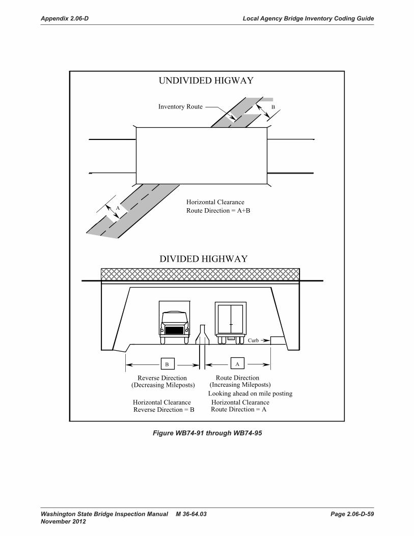
Appendix 2.06-D Local Agency Bridge Inventory Coding Guide
Washington State Bridge Inspection Manual M 36-64.03 Page 2.06-D-59 November 2012
Bridge Inventory Coding Guide
Page 2-64 Washington State Bridge Inspection ManualJanuary 2002
Figure WB74 - 91 through 95
Inventory Route
AB
Horizontal ClearanceRoute Direction = A+B
UNDIVIDED HIGWAY
DIVIDED HIGHWAY
Reverse Direction(Decreasing Mileposts)
Route Direction(Increasing Mileposts)
Horizontal ClearanceReverse Direction = B
Horizontal ClearanceRoute Direction = A
B
Curb
Looking ahead on mile posting
A
KMA
Figure WB74-91 through WB74-95

Local Agency Bridge Inventory Coding Guide Appendix 2.06-D
Page 2.06-D-60 Washington State Bridge Inspection Manual M 36-64.03 November 2012
horiz_clrnc_rvrs Horizontal Clearance, Reverse Direction (Required)WB74-95FHWA Item 047 This is the minimum horizontal clearance for that side of the divided roadway
which carries traffic in the direction of decreasing mileposts, or, in the absence of mileposts, to the south or west (see Figure WB74-91). This is called the reverse direction. The measurement shall be coded in feet and inches.
If the inventory route is not a divided highway, leave this field blank.
vert_clrnc_route_max Maximum Vertical Clearance Route DirectionWB74-99FHWA Item 010 A value must be entered in this field to indicate If any height restrictions
(imposed by a structural member such as sway bracing on trusses, a bridge passing over this route, the mouth of a tunnel) apply to loads carried on the inventory route. This measurement is coded in feet and inches. If the inventory route is carried on or under the bridge, code the vertical clearance for the 10-foot width of the traveled part of the roadway which will allow passage of the highest vehicle without striking the bridge. The maximum vertical height allowed in any 10 foot roadway width is the least vertical clearance in the 10 foot width of the roadway with the maximum vertical clearance. If there is no vertical restriction leave the field blank (see Figure WB74-99).
Washington State Bridge Inspection Manual Page 2-65January 2002
Bridge Inventory Coding Guide
horiz_clrnc_rvrs Horizontal Clearance, Reverse Direction (Required)WB74 - 95FHWA Item 047 This is the minimum horizontal clearance for that side of the divided
roadway which carries traffic in the direction of decreasing mileposts,or, in the absence of mileposts, to the south or west (see FigureWB74 - 91). This is called the reverse direction. The measurementshould be coded in feet and inches.
If the inventory route is not a divided highway, leave this field blank.
vert_clrnc_route_max Maximum Vertical Clearance Route DirectionWB74 - 99FHWA Item 010 A value must be entered in this field to indicate if any height
restrictions (imposed by this bridge) apply to loads carried on theinventory route. This measurement is coded in feet and inches. If theinventory route is carried on or under the bridge, code the verticalclearance for the 10-foot width of the traveled part of the roadwaywhich will allow passage of the highest vehicle without striking thebridge. The maximum vertical height allowed in any 10 foot roadwaywidth is the least vertical clearance in the 10 foot width of the roadwaywith the maximum vertical clearance. If there is no vertical restrictioncaused by the bridge, leave the field blank (see Figure WB74 - 99).
Figure WB74 - 99Figure WB74-99

Appendix 2.06-D Local Agency Bridge Inventory Coding Guide
Washington State Bridge Inspection Manual M 36-64.03 Page 2.06-D-61 November 2012
detour_length Detour Length (Fatal)WB74-103FHWA Item 019 The detour length is the distance a vehicle, when starting at one end of the
bridge, must travel along the shortest alternate route to reach the opposite end of the bridge. The total detour length is coded to the nearest mile. To be an acceptable detour, an alternate route must be a public road and must be able to provide a similar level of load-carrying capacity as the inventory route (see Figure WB74-103).
If the bridge is at an interchange and a ground-level bypass or the other side of a parallel bridge can be used as the detour route, code Ø in this field.
If the bridge is not at an interchange and a ground level bypass or parallel bridge can be used as a detour route, code Ø1.
If the bridge is on a dead-end road where there is no alternate route, or if the distance that must be traveled is greater than 98 miles, code 99 in the field.
Bridge Inventory Coding Guide
Page 2-66 Washington State Bridge Inspection ManualJanuary 2002
detour_length Detour Length (Fatal)WB74 - 103FHWA Item 019 The detour length is the distance a vehicle, when starting at one end
of the bridge, must travel along the shortest alternate route to reachthe opposite end of the bridge. The total detour length is coded to thenearest mile. To be an acceptable detour, an alternate route must be apublic road and must be able to provide a similar level of load-carryingcapacity as the inventory route (see Figure WB74 - 103).
If the bridge is at an interchange and a ground-level bypass or the otherside of a parallel bridge can be used as the detour route, code /0 /0 inthis field.
If the bridge is not at an interchange and a ground level bypass orparallel bridge can be used as a detour route, code /01.
If the bridge is on a dead-end road where there is no alternate route, orif the distance that must be traveled is greater than 98 miles, code 99 inthe field.
Figure WB74 - 103Figure WB74-103

Local Agency Bridge Inventory Coding Guide Appendix 2.06-D
Page 2.06-D-62 Washington State Bridge Inspection Manual M 36-64.03 November 2012

Appendix 2.06-D Local Agency Bridge Inventory Coding Guide
Washington State Bridge Inspection Manual M 36-64.03 Page 2.06-D-63 November 2012
fed_main_material_ Main Span Material (Required)WB75-32FHWA Item 043A This code describes the kind of material and /or design used in the bridge’s
main span.
When coding this field, indicate the composition of the superstructure’s main load carrying member. That is, if the bridge has a concrete deck carried on timber stringers, code 7 (for timber). Or, if the bridge has a concrete deck carried on steel beams, code 3 (for steel).
1 Concrete 2 Concrete continuous 3 Steel 4 Steel continuous 5 Prestressed concrete 6 Prestressed concrete continuous 7 Timber 8 Masonry 9 Aluminum, wrought iron, cast iron 0 Other
Both pre-tensioned concrete and post-tensioned concrete are considered prestressed concrete.
fed_main_design_ Main Span Design (Required)WB75-33FHWA Item 043B This code describes the predominant type of design and/or type of construction
used in the bridge’s main span. This is a Fatal Field for WSDOT only.
01 Slab 02 Stringer/multi-beam or girder 03 Girder and floorbeam system 04 Tee beam 05 Box beam/box girder-multiple
Bridge Inventory Coding Guide
Page 2-68 Washington State Bridge Inspection ManualJanuary 2002
fed_aprch_material_ Approach Span Material (Required)WB75 - 35FHWA Item 044A This code identifies the kind of material used in the bridge’s
approach spans.
1 Concrete2 Concrete continuous3 Steel4 Steel continuous5 Prestressed concrete6 Prestressed concrete continuous7 Timber8 Masonry9 Aluminum, wrought iron, cast iron0/ Other
When coding this field, indicate the composition of thesuperstructure’s main load carrying member. That is, if the bridgehas a concrete deck carried on timber stringers, code 7 (for timber).Or, if the bridge has a concrete deck carried on steel beams, code 3(for steel).
fed_aprch_design_ Approach Span Design (Required)WB75 - 36FHWA Item 044B This code identifies the predominant type of design and/or
type of construction used in the bridge’s approach spans. BMSelement descriptions may differ from the following approach spandesign types.
0/ 1 Slab0/ 2 Stringer/multi-beam or girder0/ 3 Girder and floorbeam system0/ 4 Tee beam0/ 5 Box beam/box girder - multiple0/ 6 Box beam/box girder - single or spread0/ 7 Rigid frame0/ 8 Orthotropic0/ 9 Truss - deck10/ Truss - through11 Arch - deck12 Arch - through13 Suspension14 Stayed girder15 Movable - lift16 Movable - bascule17 Movable - swing18 Tunnel19 Culvert20/ Mixed types21 Segmental box girder22 Channel beam (bathtub unit)0/ 0/ Other
06 Box beam/box girder-single or spread
Bridge Inventory Coding Guide
Page 2-68 Washington State Bridge Inspection ManualJanuary 2002
fed_aprch_material_ Approach Span Material (Required)WB75 - 35FHWA Item 044A This code identifies the kind of material used in the bridge’s
approach spans.
1 Concrete2 Concrete continuous3 Steel4 Steel continuous5 Prestressed concrete6 Prestressed concrete continuous7 Timber8 Masonry9 Aluminum, wrought iron, cast iron0/ Other
When coding this field, indicate the composition of thesuperstructure’s main load carrying member. That is, if the bridgehas a concrete deck carried on timber stringers, code 7 (for timber).Or, if the bridge has a concrete deck carried on steel beams, code 3(for steel).
fed_aprch_design_ Approach Span Design (Required)WB75 - 36FHWA Item 044B This code identifies the predominant type of design and/or
type of construction used in the bridge’s approach spans. BMSelement descriptions may differ from the following approach spandesign types.
0/ 1 Slab0/ 2 Stringer/multi-beam or girder0/ 3 Girder and floorbeam system0/ 4 Tee beam0/ 5 Box beam/box girder - multiple0/ 6 Box beam/box girder - single or spread0/ 7 Rigid frame0/ 8 Orthotropic0/ 9 Truss - deck10/ Truss - through11 Arch - deck12 Arch - through13 Suspension14 Stayed girder15 Movable - lift16 Movable - bascule17 Movable - swing18 Tunnel19 Culvert20/ Mixed types21 Segmental box girder22 Channel beam (bathtub unit)0/ 0/ Other
07 Rigid frame 08 Orthotropic 09 Truss-deck 10 Truss – through (Includes Pony Truss) 11 Arch-deck 12 Arch – through (With or without overhead lateral bracing) 13 Suspension 14 Stayed girder 15 Movable-lift 16 Movable-bascule 17 Movable-swing 18 Tunnel 19 Culvert
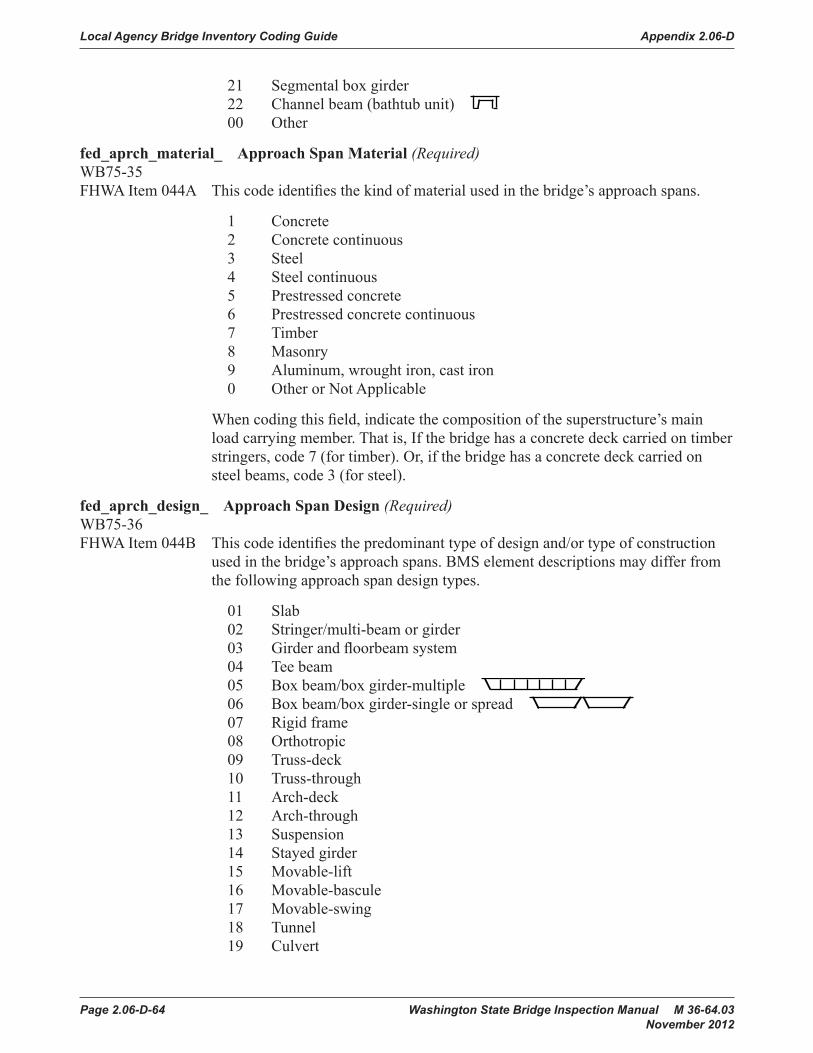
Local Agency Bridge Inventory Coding Guide Appendix 2.06-D
Page 2.06-D-64 Washington State Bridge Inspection Manual M 36-64.03 November 2012
21 Segmental box girder 22 Channel beam (bathtub unit)
Bridge Inventory Coding Guide
Page 2-68 Washington State Bridge Inspection ManualJanuary 2002
fed_aprch_material_ Approach Span Material (Required)WB75 - 35FHWA Item 044A This code identifies the kind of material used in the bridge’s
approach spans.
1 Concrete2 Concrete continuous3 Steel4 Steel continuous5 Prestressed concrete6 Prestressed concrete continuous7 Timber8 Masonry9 Aluminum, wrought iron, cast iron0/ Other
When coding this field, indicate the composition of thesuperstructure’s main load carrying member. That is, if the bridgehas a concrete deck carried on timber stringers, code 7 (for timber).Or, if the bridge has a concrete deck carried on steel beams, code 3(for steel).
fed_aprch_design_ Approach Span Design (Required)WB75 - 36FHWA Item 044B This code identifies the predominant type of design and/or
type of construction used in the bridge’s approach spans. BMSelement descriptions may differ from the following approach spandesign types.
0/ 1 Slab0/ 2 Stringer/multi-beam or girder0/ 3 Girder and floorbeam system0/ 4 Tee beam0/ 5 Box beam/box girder - multiple0/ 6 Box beam/box girder - single or spread0/ 7 Rigid frame0/ 8 Orthotropic0/ 9 Truss - deck10/ Truss - through11 Arch - deck12 Arch - through13 Suspension14 Stayed girder15 Movable - lift16 Movable - bascule17 Movable - swing18 Tunnel19 Culvert20/ Mixed types21 Segmental box girder22 Channel beam (bathtub unit)0/ 0/ Other
00 Other
fed_aprch_material_ Approach Span Material (Required)WB75-35FHWA Item 044A This code identifies the kind of material used in the bridge’s approach spans.
1 Concrete 2 Concrete continuous 3 Steel 4 Steel continuous 5 Prestressed concrete 6 Prestressed concrete continuous 7 Timber 8 Masonry 9 Aluminum, wrought iron, cast iron 0 Other or Not Applicable
When coding this field, indicate the composition of the superstructure’s main load carrying member. That is, If the bridge has a concrete deck carried on timber stringers, code 7 (for timber). Or, if the bridge has a concrete deck carried on steel beams, code 3 (for steel).
fed_aprch_design_ Approach Span Design (Required)WB75-36 FHWA Item 044B This code identifies the predominant type of design and/or type of construction
used in the bridge’s approach spans. BMS element descriptions may differ from the following approach span design types.
01 Slab 02 Stringer/multi-beam or girder 03 Girder and floorbeam system 04 Tee beam 05 Box beam/box girder-multiple
Bridge Inventory Coding Guide
Page 2-68 Washington State Bridge Inspection ManualJanuary 2002
fed_aprch_material_ Approach Span Material (Required)WB75 - 35FHWA Item 044A This code identifies the kind of material used in the bridge’s
approach spans.
1 Concrete2 Concrete continuous3 Steel4 Steel continuous5 Prestressed concrete6 Prestressed concrete continuous7 Timber8 Masonry9 Aluminum, wrought iron, cast iron0/ Other
When coding this field, indicate the composition of thesuperstructure’s main load carrying member. That is, if the bridgehas a concrete deck carried on timber stringers, code 7 (for timber).Or, if the bridge has a concrete deck carried on steel beams, code 3(for steel).
fed_aprch_design_ Approach Span Design (Required)WB75 - 36FHWA Item 044B This code identifies the predominant type of design and/or
type of construction used in the bridge’s approach spans. BMSelement descriptions may differ from the following approach spandesign types.
0/ 1 Slab0/ 2 Stringer/multi-beam or girder0/ 3 Girder and floorbeam system0/ 4 Tee beam0/ 5 Box beam/box girder - multiple0/ 6 Box beam/box girder - single or spread0/ 7 Rigid frame0/ 8 Orthotropic0/ 9 Truss - deck10/ Truss - through11 Arch - deck12 Arch - through13 Suspension14 Stayed girder15 Movable - lift16 Movable - bascule17 Movable - swing18 Tunnel19 Culvert20/ Mixed types21 Segmental box girder22 Channel beam (bathtub unit)0/ 0/ Other
06 Box beam/box girder-single or spread
Bridge Inventory Coding Guide
Page 2-68 Washington State Bridge Inspection ManualJanuary 2002
fed_aprch_material_ Approach Span Material (Required)WB75 - 35FHWA Item 044A This code identifies the kind of material used in the bridge’s
approach spans.
1 Concrete2 Concrete continuous3 Steel4 Steel continuous5 Prestressed concrete6 Prestressed concrete continuous7 Timber8 Masonry9 Aluminum, wrought iron, cast iron0/ Other
When coding this field, indicate the composition of thesuperstructure’s main load carrying member. That is, if the bridgehas a concrete deck carried on timber stringers, code 7 (for timber).Or, if the bridge has a concrete deck carried on steel beams, code 3(for steel).
fed_aprch_design_ Approach Span Design (Required)WB75 - 36FHWA Item 044B This code identifies the predominant type of design and/or
type of construction used in the bridge’s approach spans. BMSelement descriptions may differ from the following approach spandesign types.
0/ 1 Slab0/ 2 Stringer/multi-beam or girder0/ 3 Girder and floorbeam system0/ 4 Tee beam0/ 5 Box beam/box girder - multiple0/ 6 Box beam/box girder - single or spread0/ 7 Rigid frame0/ 8 Orthotropic0/ 9 Truss - deck10/ Truss - through11 Arch - deck12 Arch - through13 Suspension14 Stayed girder15 Movable - lift16 Movable - bascule17 Movable - swing18 Tunnel19 Culvert20/ Mixed types21 Segmental box girder22 Channel beam (bathtub unit)0/ 0/ Other
07 Rigid frame 08 Orthotropic 09 Truss-deck 10 Truss-through 11 Arch-deck 12 Arch-through 13 Suspension 14 Stayed girder 15 Movable-lift 16 Movable-bascule 17 Movable-swing 18 Tunnel 19 Culvert

Appendix 2.06-D Local Agency Bridge Inventory Coding Guide
Washington State Bridge Inspection Manual M 36-64.03 Page 2.06-D-65 November 2012
20 Mixed types 21 Segmental box girder 22 Channel beam (bathtub unit)
Bridge Inventory Coding Guide
Page 2-68 Washington State Bridge Inspection ManualJanuary 2002
fed_aprch_material_ Approach Span Material (Required)WB75 - 35FHWA Item 044A This code identifies the kind of material used in the bridge’s
approach spans.
1 Concrete2 Concrete continuous3 Steel4 Steel continuous5 Prestressed concrete6 Prestressed concrete continuous7 Timber8 Masonry9 Aluminum, wrought iron, cast iron0/ Other
When coding this field, indicate the composition of thesuperstructure’s main load carrying member. That is, if the bridgehas a concrete deck carried on timber stringers, code 7 (for timber).Or, if the bridge has a concrete deck carried on steel beams, code 3(for steel).
fed_aprch_design_ Approach Span Design (Required)WB75 - 36FHWA Item 044B This code identifies the predominant type of design and/or
type of construction used in the bridge’s approach spans. BMSelement descriptions may differ from the following approach spandesign types.
0/ 1 Slab0/ 2 Stringer/multi-beam or girder0/ 3 Girder and floorbeam system0/ 4 Tee beam0/ 5 Box beam/box girder - multiple0/ 6 Box beam/box girder - single or spread0/ 7 Rigid frame0/ 8 Orthotropic0/ 9 Truss - deck10/ Truss - through11 Arch - deck12 Arch - through13 Suspension14 Stayed girder15 Movable - lift16 Movable - bascule17 Movable - swing18 Tunnel19 Culvert20/ Mixed types21 Segmental box girder22 Channel beam (bathtub unit)0/ 0/ Other
00 Other or Not Applicable
main_span_qty Number of Main Spans (Required)WB75-38FHWA Item 045 This is the number of spans in the main or major unit of the bridge. A bridge will
contain at least one span. Most bridges will contain a main unit with no approach spans. In such cases, code the number of spans in this field and enter zero in WB75-41. If the bridge contains a main section and approach sections, code the number of spans in the main section only in this field, and code the number of spans in the approach section(s) in WB75-41.
aprch_span_qty Number of Approach Spans (Required)WB75-41FHWA Item 046 This is the number of spans in the approach(es) to the main section of the bridge.
If the bridge has no approach spans, enter zero.
serv_on_code Service On (Fatal)WB75-44FHWA Item 042A This field describes the type of service carried on the bridge.
1 Highway 2 Railroad 3 Pedestrian exclusively 4 Highway and railroad 5 Highway and pedestrian 6 Overpass bridge at an interchange or second level of a multilevel interchange 7 Third level of a multilevel interchange 8 Fourth level of a multilevel interchange 9 Building or plaza 0 Other
serv_under_code Service Under (Required)WB75-45FHWA Item 042B This field describes the type of service under the bridge.
1 Highway, with or without pedestrian traffic 2 Railroad 3 Pedestrians exclusively 4 Highway and railroad 5 Waterway 6 Highway and waterway 7 Railroad and waterway 8 Highway, waterway, and railroad 9 Relief for waterway 0 Other

Local Agency Bridge Inventory Coding Guide Appendix 2.06-D
Page 2.06-D-66 Washington State Bridge Inspection Manual M 36-64.03 November 2012
fed_deck_type Deck Type (Required)WB75-46FHWA Item 107 This is the federal code for the type of deck system on the bridge.
If the deck is composed of more than one type of material, indicate what type of material is the most predominant.
If the bridge is a culvert and the roadway is carried on fill, code N to indicate that the deck type is not applicable. WB75-47, Wearing Surface, WB75-48, Membrane, and WB75-49, Deck Protection will also be coded N in this case.
1 Concrete cast-in-place 2 Concrete precast panels 3 Steel grating-open 4 Steel grating-filled with concrete 5 Steel plate (including orthotropic) 6 Corrugated steel 7 Aluminum 8 Treated timber 9 Untreated timber Ø Other A Filled arches B Precast integral with beam N Not applicable (bridge has no deck)
fed_wear_surf Wearing Surface (Required)WB75-47FHWA Item 108A This is the federal code for the type of wearing surface on the bridge deck.
1 Concrete (also monolithic decks) 2 Integral concrete (non-modified concrete layer added) 3 Latex modified or other modified concrete 4 Low slump concrete 5 Protective overlays (epoxy, methyl methacrylate, polyester) 6 Bituminous (i.e., ACP or BST) 7 Timber 8 Gravel (ballast) 9 Other Ø None (traffic does not ride on wearing surface) N Not applicable (bridge has no deck)

Appendix 2.06-D Local Agency Bridge Inventory Coding Guide
Washington State Bridge Inspection Manual M 36-64.03 Page 2.06-D-67 November 2012
fed_membrane Membrane (Required)WB75-48FHWA Item 108B This is the federal code for the type of deck membrane used on the bridge.
1 Built-up (roofing tar or liquid asphalt) 2 Preformed fabric 3 Epoxy 8 Unknown 9 Other Ø None N Not applicable (bridge has no deck)
fed_deck_prot Deck Protection (Required)WB75-49FHWA Item 108C This is the federal code for the type of deck-protective system on the bridge.
1 Epoxy coated reinforcing 2 Galvanized reinforcing 3 Other coated reinforcing bar 4 Cathodic protection 6 Polymer impregnated 7 Internally sealed 8 Unknown 9 Other Ø None N Not applicable (bridge has no deck)
design_load_ Design Load (Required)WB75-50FHWA Item 031 This code expresses the type and amount of live load the bridge has been
designed to carry. Classify any other loading, when feasible, using the nearest equivalent valid code.
1 H 10 2 H 15 3 HS 15 4 H 20 5 HS 20 6 HS 20 + Military Mod 7 Pedestrian 8 Railroad 9 HS 25 or Greater 0 Unknown A HL-93 B Greater than HL-93 C Other

Local Agency Bridge Inventory Coding Guide Appendix 2.06-D
Page 2.06-D-68 Washington State Bridge Inspection Manual M 36-64.03 November 2012
oper_rtng_meth Operating Rating Method (Required)WB75-51FHWA Item 063 Code this field with one of the following codes to indicate which load rating
method was used to determine the Operating Rating for this bridge. FHWA has chosen the Load Factor Method as the standard for computing Operating and Inventory ratings reported to the NBI. For proper coding, see load rating section of Chapter 5.
F Load Factor reported in tons W Working Stress reported in tons L Load and Resistance Factor reported in tons T Load Testing N No rating analysis was performed A Administrative 6 Load Factor Rating reported by Rating Factor using HS-20 loading 7 Working Stress Rating reported by Rating Factor using HS-20 loading 8 Load and Resistance Factor reported by Rating Factor using HL-93 loading
oper_rtng_tons Operating Rating Tons (Required)WB75-52FHWA Item 064 This field contains a value which indicates the absolute maximum gross weight
(in tons) to which the bridge may be subjected for the type of vehicle used in the operating rating.
HS loading shall be used in the rating. The following conditions will apply:
• If the bridge will not carry a minimum of 3 tons of live load, code zero, and consistent with the direction of the AASHTO Manual for Condition Evaluation of Bridges, it shall be closed.
• If the bridge is a temporary bridge, code zero in this field (since there is no permanent bridge) even though the temporary bridge is rated for as much as a full legal load.
• If the bridge is shored up or repaired on a temporary basis, it is considered a temporary bridge and should be coded as If the shoring were not in place.
• Code 99 for a bridge under sufficient fill such that according to AASHTO design the live load is insignificant in the bridge load capacity.

Appendix 2.06-D Local Agency Bridge Inventory Coding Guide
Washington State Bridge Inspection Manual M 36-64.03 Page 2.06-D-69 November 2012
invt_rtng_meth Inventory Rating Method (Required)WB75-54FHWA Item 065 Code this field with one of the codes listed below to indicate which load rating
method was used to determine the Inventory Rating coded for this bridge. FHWA has chosen the Load Factor Method as the standard for computing Operating and Inventory rating reported to the NBI.
F Load Factor reported in tons W Working Stress reported in tons L Load and Resistance Factor reported in tons T Load Testing N No rating analysis was performed A Administrative 6 Load Factor Rating reported by Rating Factor using HS-20 loading 7 Working Stress Rating reported by Rating Factor using HS-20 loading 8 Load and Resistance Factor reported by Rating Factor using HL-93 loading
invt_rtng_tons Inventory Rating Tons (Required)WB75-55FHWA Item 066 This is the capacity rating, in tons, which results in a load level which can safely
utilize an existing bridge for an indefinite period of time. HS loading shall be used in the rating. The following conditions will apply:
• If the bridge is a temporary bridge, code zero in this field (since there is no permanent bridge) even though the temporary bridge is rated for as much as a full legal load.
• If the bridge is shored up or repaired on a temporary basis, it is considered a temporary bridge and should be coded as If the shoring were not in place.
• Code 99 for a bridge under sufficient fill such that according to AASHTO design the live load is insignificant in the bridge load capacity.
op_rating_factor Operating Rating Factor If Item 551 is coded 6, 7, or 8, the operating rating factor is entered here as
a 3-digit number without the decimal point.
inv_rating_factor Inventory Rating Factor If Item 554 is coded 6, 7, or 8, the inventory rating factor is entered here as
a 3-digit number without the decimal point.
design_exception_date Design Exception Date (Optional)WB75-57 If a design exception has been granted by the FHWA to permit a deviation from
required standards, this is the effective date of FHWA approval.
For example, if approval to build a one-lane bridge on a low volume road was granted, enter the date approval was given for this exception. Indicate the date in the MMDDYYYY format. If no design exception has been granted, leave the field blank.

Local Agency Bridge Inventory Coding Guide Appendix 2.06-D
Page 2.06-D-70 Washington State Bridge Inspection Manual M 36-64.03 November 2012
fed_aid_project Federal Aid Project (Optional)WB75-65 This is the most recent federal aid project number under which federal funds
have been used for construction or reconstruction from the year 1970 forward.
Left justify and leave unused columns blank. If the construction work has been assigned more than one federal aid project number, enter the number for the most recently completed (or current) portion of the project. If federal funds have not been used, leave the field blank.
border_state_code Border Bridge State Code (Required)WB75-85FHWA Item 098A For bridges which do not cross a Washington State border, leave this field blank.
This is the code of the neighboring state with which Washington State, or a Local Agency within Washington State, shares responsibility for improvements on the existing bridge which crosses state borders. Valid codes are:
160 Idaho 410 Oregon CAN Canada
border_pct Border Bridge Percent (Required)WB75-88FHWA Item 098B For bridges which do not cross a Washington State border, leave the field blank.
This is the percentage of responsibility a neighboring state accepts for improvements on an existing bridge which crosses state borders.
Code the percentage of square footage of the existing bridge that the neighbor is responsible for funding.
border_structure_id Border Bridge Structure Identifier (Required)WB75-90FHWA Item 099 If the bridge does not cross a Washington State border, leave this field blank.
This is the neighboring state’s 15 character National Bridge Inventory Structure Number.
The entire 15 character field must be filled in exactly, including any blank spaces and any leading, trailing, or imbedded zeros.
The Bridge Inspection Report (BIR) NBI section has numbers in parentheses that reflect the inventory form WB76. For example, WB76-57, Structural Adequacy Appraisal, is (657) on the BIR.

Appendix 2.06-D Local Agency Bridge Inventory Coding Guide
Washington State Bridge Inspection Manual M 36-64.03 Page 2.06-D-71 November 2012
alphabetic_span Alphabetic Span Type(s) (Optional) Use the table below to identify each group of span types that make up the
entire bridge. Separate each span group by a space. List the Main Span first. The sequence for listing the Approach Spans should be longest to shortest but is somewhat arbitrary. The Alphabetic Span type for the Main and Approach spans must be compatible with Items 532, 533, 535 and 536 respectively.
As an example suppose you have a Steel Through Truss with a 140’ Creosote Treated Timber approach at one end of the truss and a 30’ Concrete t-beam at the other approach.
Items 532 would = 3 and 533 would = 10. Items 535 would = 1 or 7 and 536 would = 04 or 02 depending on which approach you choose to list.
The Alphabetic Span would be entered as follows:
STrus TTC CTB
Alphabetic Span Definition
Alphabetic Span Definition
Aculv Aluminum Culvert PRCB Precast Reinforced Concrete BeamBAS Bascule Lift Span SA Steel Arch CA Concrete Arch STA Steel Tied Arch
CEFA Concrete Earth Filled Arch SRB Steel Rolled BeamCBox Concrete Box Girder SBG Steel Box GirderCCulv Concrete Culvert SCulv Steel CulvertCFP Concrete Floating Pontoon SFP Steel Floating PontoonCG Concrete Girder SG Steel Girder (weld or rivet)CS Concrete Slab SLS Steel Lift Span
CSS Cable Stayed Span SSCG Steel Stayed Concrete GirderCVS Concrete Voided Slab SSwS Steel Swing Span
CSTP Concrete Slab on Timber Piling Strus Steel TrussCTB Concrete T-Beam SSusS Steel Suspension Span
CTrus Concrete Truss TCulv Timber CulvertCTun Concrete Lined Tunnel TS Timber SlabCESB Concrete Encased Steel Beam TTLB Treated Timber Laminated BeamLIDTun Cut and Cover (LID) Tunnel TTTrus Treated Timber TrussMCulv Masonry Culvert TTS Treated Timber (Salts) BridgePCG Prestressed Concrete Girder TTC Treated Timber (Creosote) BridgePCS Prestressed Concrete Slab TLTun Timber Lined Tunnel
PCBTG Prestressed Concrete Bulb-T Girder UTun Unlined TunnelPCMWG Prestressed Concrete Multi-Web Girder Plaza Park Plaza Structures
PCTG Prestressed Concrete Trapezoidal Girder UTTrus Untreated Timber TrussPTCTB Post-Tensioned Concrete T-Beam UT Untreated Timber BridgePTCBox Post-Tensioned Concrete Box Girder UTLB Untreated Timber Laminated BeamPTCSeg Post-Tensioned Segmental Box Girder WSG Weathering Steel Girder

Local Agency Bridge Inventory Coding Guide Appendix 2.06-D
Page 2.06-D-72 Washington State Bridge Inspection Manual M 36-64.03 November 2012
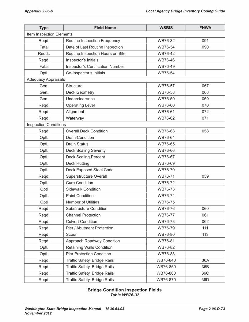
Appendix 2.06-D Local Agency Bridge Inventory Coding Guide
Washington State Bridge Inspection Manual M 36-64.03 Page 2.06-D-73 November 2012
Type Field Name WSBIS FHWAItem Inspection Elements
Reqd. Routine Inspection Frequency WB76-32 091Fatal Date of Last Routine Inspection WB76-34 090
Reqd.. Routine Inspection Hours on Site WB76-42Reqd. Inspector’s Initials WB76-46Fatal Inspector’s Certification Number WB76-49Optl. Co-Inspector’s Initials WB76-54
Adequacy AppraisalsGen. Structural WB76-57 067Gen. Deck Geometry WB76-58 068Gen. Underclearance WB76-59 069Reqd. Operating Level WB76-60 070Reqd. Alignment WB76-61 072Reqd. Waterway WB76-62 071
Inspection ConditionsReqd. Overall Deck Condition WB76-63 058Optl. Drain Condition WB76-64Optl. Drain Status WB76-65Optl. Deck Scaling Severity WB76-66Optl. Deck Scaling Percent WB76-67Optl. Deck Rutting WB76-69Optl. Deck Exposed Steel Code WB76-70Reqd. Superstructure Overall WB76-71 059Optl. Curb Condition WB76-72Optl Sidewalk Condition WB76-73Optl. Paint Condition WB76-74Optl Number of Utilities WB76-75
Reqd. Substructure Condition WB76-76 060Reqd. Channel Protection WB76-77 061Reqd. Culvert Condition WB76-78 062Reqd. Pier / Abutment Protection WB76-79 111Reqd. Scour WB76-80 113Reqd. Approach Roadway Condition WB76-81Optl. Retaining Walls Condition WB76-82Optl. Pier Protection Condition WB76-83Reqd. Traffic Safety, Bridge Rails WB76-840 36AReqd. Traffic Safety, Bridge Rails WB76-850 36BReqd. Traffic Safety, Bridge Rails WB76-860 36CReqd. Traffic Safety, Bridge Rails WB76-870 36D
Bridge Condition Inspection FieldsTable WB76-32

Local Agency Bridge Inventory Coding Guide Appendix 2.06-D
Page 2.06-D-74 Washington State Bridge Inspection Manual M 36-64.03 November 2012
inspn_freq Routine Inspection Frequency (Required)WB76-32FHWA Item 091 This is the number of months between consecutive routine inspections.
The standard maximum frequency of NBI bridges for Routine Inspections is 24 months.
last_inspn_date Date of Last Routine Inspection (Fatal)WB76-34FHWA Item 090 This is the date the most recent routine inspection was performed on this bridge.
inspn_hours Routine Inspection Hours on Site (Optional)WB76-42 This is the total number of inspection hours (to the tenth of an hour) that the
inspection team spent on the bridge during a Routine Inspection.
inspr_initials Inspector’s Initials (Required)WB76-46 These are the initials of the inspector whose certification number appears in
WB76-49.
cert_no Inspector’s Certification Number (Fatal)WB76-49 This is the certification number of the lead inspector at the bridge site performing
the routine inspection.
co_inspr_initials Co-Inspector’s Initials (Optional)WB76-54 These are the initials of the individual who assisted the lead inspector in
performing a routine inspection.
Adequacy Appraisal There are six fields used to appraise the adequacy of the bridge in relation to the level of service it provides on the highway system of which it is a part. To make this appraisal, the present condition of the bridge is compared to the condition of a new bridge built to current standards for that particular classification of road (with the exception of underclearance).
The appraisal codes for Structural Adequacy Appraisal, Deck Geometry Appraisal, and Underclearance Adequacy Appraisal are computed automatically by the WSBIS system.
The appraisal codes for Operating Level, Alignment Adequacy Appraisal, and Water Way Adequacy Appraisal are not computed automatically and must be entered by the bridge inspector. See the field descriptions that follow.

Appendix 2.06-D Local Agency Bridge Inventory Coding Guide
Washington State Bridge Inspection Manual M 36-64.03 Page 2.06-D-75 November 2012
structure_adqcy Structural Adequacy Appraisal (Generated)WB76-57FHWA Item 067 The value in this field is generated by the WSBIS system and rates the adequacy
of the structure’s condition, taking into account any major structural deficiencies. This rating is based on the overall condition of the superstructure, substructure, the inventory rating, and the ADT.
Table WB76-57 explains how the inventory rating may further lower this code. The code for this item is no higher than the lowest of the condition codes for Superstructure Overall, Substructure Condition, or Culvert Condition.
ADT Structural Adequacy Appraisal
Rating Code
0-500 501-5000 >5000
Inventory Rating HS Truck (Tons)
Not Applicable 9
36 36 36 8
31 31 31 7
23 25 27 6
18 20 22 5
12 14 18 4
Inventory rating less than value in rating code of 4 and requiring corrective action. 3
Inventory rating is less than above and bridge requires replacement, WB78-44 is coded 31 or 32. 2
Bridge is closed and requires replacement. Ø
Structural Adequacy Appraisal RatingTable WB76-57

Local Agency Bridge Inventory Coding Guide Appendix 2.06-D
Page 2.06-D-76 Washington State Bridge Inspection Manual M 36-64.03 November 2012
deck_geometry_aprsl Deck Geometry Appraisal (Generated)WB76-58FHWA Item 068 The value in this field is generated by the WSBIS system. This is the adequacy
appraisal rating of the bridge’s deck geometry. The level of service provided by the bridge is evaluated with respect to the highway system of which it is a part. This appraisal is based on the number of traffic lanes, the curb-to-curb width, the minimum vertical clearance over the bridge deck, the ADT, and the federal functional classification.
The following Tables, WB76-58A through E, explain how the values are determined with respect to the highway system of which the bridge is a part. The lowest code determined from the tables is used.
Curb-to-Curb Bridge Roadway Width (In Feet) Deck Geometry Appraisal
Rating Code
Average Daily Traffic (ADT) (Both Directions)
0-100 101-400 401-1000 1001-2000 2001-5000 >5000
Not Applicable 9
≥ 32 ≥ 36 ≥ 40 ≥ 44 > 44 > 44 8
28 32 36 40 44 44 7
24 28 30 34 40 44 6
20 24 26 28 34 38 5
18 20 22 24 28 32 (28) 4
16 18 20 22 26 30 (26) 3
Bridge is open and has a width less than required for a rating code of 3 and WB78-44 is coded 31.
2
Bridge is closed. Ø
Notes:1. For bridges longer than 200 feet, use the values shown in parentheses.2. Use the lower rating code for roadway widths between those shown.3. For bridges with three or more undivided lanes of two-way traffic, use Table WB76-58C under
the column NUMBER of LANES (Other Roadways).4. For bridges with one-lane and one-way traffic.
Deck Geometry Appraisal Rating Two-Lane Bridge With Two-Way Traffic or One-Lane With One-Way Traffic
Table WB76-58A

Appendix 2.06-D Local Agency Bridge Inventory Coding Guide
Washington State Bridge Inspection Manual M 36-64.03 Page 2.06-D-77 November 2012
Curb-to-Curb Bridge Roadway Width (In Feet)
Deck Geometry Appraisal Rating Code
Average Daily Traffic (ADT) (Both Directions)0-100 >100
Not Applicable 915′11″ – 8
15 – 714 – 613 – 512 – 411 15′11″ 3
Bridge is open and has a width less than required for a rating code of 3 and WB78-44 is coded 31. 2
Bridge is closed. ØNotes:1. Use the lower rating code for a roadway widths between those shown.2. All single lane bridges with a deck width less than 16 feet and an ADT > 100 should be rated at 3 or below.
Deck Geometry Appraisal Rating One-Lane Bridge With Two-Way TrafficTable WB76-58B
Curb-to-Curb Bridge Roadway Width (In Feet) Two or More Lanes in Each Direction
Deck Geometry Appraisal
Rating CodeNumber of Lanes (Interstate) Number of Lanes (Other Roadways)2 Lanes > 2 Lanes 2 Lanes > 2 Lanes
Not Applicable 9≥ 42 ≥ 12N + 24 ≥ 42 ≥ 12N + 18 840 12N + 20 38 12N + 15 738 12N + 16 36 12N + 12 636 12N + 14 33 11N + 10 5
34 (29) 11N + 12 (11N + 7) 30 11N + 6 433 (28) 11N + 11 (11N + 6) 27 11N + 5 3
Bridge is open and has a width less than required for rating code of 3 and WB78-44 is coded 31.
2
Bridge is closed ØNotes:1. N = Number of traffic lanes.2. Use the lower rating code for roadway widths between those shown.3. For bridges longer than 200 feet, use the values shown in parentheses.
Deck Geometry Appraisal Rating Bridges With Two-Way TrafficTable WB76-58C

Local Agency Bridge Inventory Coding Guide Appendix 2.06-D
Page 2.06-D-78 Washington State Bridge Inspection Manual M 36-64.03 November 2012
Bridge/Ramp Width (In feet)Deck Geometry
Appraisal Rating Code
Number of Lanes1 Lane > 1 Lane
Not applicable 9≥ 26 ≥ 12N + 12 824 12N + 10 722 12N + 8 620 12N +6 518 12N +4 416 12N + 2 3
Bridge is open and has deck width less than required for a rating code of 3 and WB78-44 is coded 31. 2
Bridge is closed. ØNotes:1. N = Number of traffic lanes.2. Use the lower rating code for a roadway width between those shown.
Deck Geometry Appraisal Rating for Ramps With One-Way Traffic (Service Level = 7)Table WB76-58D
Functional Class
Deck Geometry Appraisal
Rating Code
Interstate and Other Freeway Other
Principal and Minor Arterials
Major and Minor Collectors and Locals
Designated Routes*
Undesignated Routes*
Minimum Vertical Clearance
Not Applicable 9≥ 17′0″ ≥ 16′0″ ≥ 16′6″ ≥ 16′6″ 816′9″ 15′6″ 15′6″ 15′6″ 716′6″ 14′6″ 14′6″ 14′6″ 615′9″ 14′3″ 14′3″ 14′3″ 515′0″ 14′0″ 14′0″ 14′0″ 4
Vertical clearance is less than value for rating of 4; corrective action is required. 3
Vertical clearance is less than value for rating of 4 and WB78-44 is coded 31; replacement is required. 2
Bridge is closed. ØNotes:*Use the first column (Designated Routes) for all routes except designated routes in urban areas where there is an alternative interstate of freeway facility with a minimum clearance of at least 16′ 0″. Use the second column (Undesignated Routes) for all undesignated interstate or freeway facilities.1. Use the lower rating code for any vertical clearance measurements between those shown.
Deck Geometry Appraisal RatingTable WB76-58E

Appendix 2.06-D Local Agency Bridge Inventory Coding Guide
Washington State Bridge Inspection Manual M 36-64.03 Page 2.06-D-79 November 2012
underclrnc_aprsl Underclearance Adequacy Appraisal (Generated)WB76-59FHWA Item 069 The code for this field is generated by the WSBIS system.
It rates the adequacy of the bridge’s underclearance. This appraisal is based on the vertical and lateral underclearances beneath the bridge as related to the federal functional classification of the roadway carried beneath the bridge. If the bridge is not over a highway or a railroad, the field will be set to 9.
See Tables WB76-59A and B for an explanation of how the values are calculated.
Functional ClassUnder-
Clearance Adequacy Appraisal
Rating Code
Interstate and Other Freeway Other
Principal and Minor Arterials
Major and Minor Collectors and Locals Railroads
Designated Routes*
Undesignated Routes*
Minimum Vertical Underclearance
Not Applicable 9
≥ 17′0″ ≥ 16′0″ ≥ 16’6″ ≥ 16′6″ ≥ 23′0″ 8
16′9″ 15′6″ 15′6″ 15′6″ 22′6″ 7
16′6″ 14′6″ 14′6″ 14′6″ 22′0″ 6
15′9″ 14′3″ 14′3″ 14′3″ 21′0″ 5
15′0″ 14′0″ 14′0″ 14′0″ 20′0″ 4
Vertical clearance is less than value for rating of 4; corrective action is required. 3
Vertical clearance is less than value for rating of 4 and WB78-44 is coded 31; replacement is required. 2
Bridge is closed. Ø
Notes:*Use the first column (Designated Routes) for all routes except designated routes in urban areas where there is an alternative interstate of freeway facility with a minimum clearance of at least 16′ 0″. Use the second column (Undesignated Routes) for all undesignated interstate or freeway facilities.1. Use the lower rating code for any vertical clearance measurements between those shown.
Underclearance Adequacy Appraisal RatingTable WB76-59A

Local Agency Bridge Inventory Coding Guide Appendix 2.06-D
Page 2.06-D-80 Washington State Bridge Inspection Manual M 36-64.03 November 2012
Functional Class
Under-clearance Adequacy Appraisal
Rating Code
One-Way Traffic Two-Way Traffic
Railroads
Principal Arterials (Interstate, etc.) Other
Principal and Minor Arterials
Major and Minor Collectors and Locals
Main Line Ramp
Lt. Rt. Lt. Rt.
Minimum Lateral Underclearance (Feet)
Not Applicable 9
≥ 30 ≥ 30 ≥ 4 ≥ 10 ≥ 30 ≥ 12 ≥ 20 8
18 21 3 9 21 11 17 7
6 12 2 8 12 10 14 6
5 11 2 6 10 8 11 5
4 10 2 4 8 6 8 4
Underclearance is less than value for rating of 4; corrective action is required. 3
Underclearance is less than value for rating of 4 and WB78-44 is coded 31; replacement is required. 2
Bridge is closed. Ø
Notes:1. Use the lower rating code for any underclearance measurements between those shown.2. Use the value from the Right Ramp column to determine the rating code when acceleration or deceleration lanes
or ramps are provided under two-way traffic.
Underclearance Adequacy RatingTable WB76-59B

Appendix 2.06-D Local Agency Bridge Inventory Coding Guide
Washington State Bridge Inspection Manual M 36-64.03 Page 2.06-D-81 November 2012
safe_load_code Operating Level (Required)WB76-60FHWA Item 070 This appraisal is a consideration of the relationship between the load that may
legally use the bridge and the desired load capacity for this type of bridge in the state of Washington. It is to be based on the bridge’s operating rating.
When the maximum legal load allowed in the state exceeds the operating rating, the bridge must be posted. This is in accordance with the requirements of the NBIS. Agencies, however, may elect to post bridges at lower rating capacities. If this is done, WB72-93 may show that the bridge is posted while the field may show that posting is not required. Such coding information is not in conflict but is acceptable and correct.
If the bridge is a temporary bridge, the operating level appraisal rating must reflect its actual load-carrying capacity at the operating rating. The rating should be made based on the loads the bridge is actually carrying. This also applies to bridges which have been shored up or repaired on a temporary basis.
Refer to Table WB76-60 and the Federal coding guide to determine the proper code to enter in this field (see Figure 5.03A-1 for AASHTO Trucks).
CodeRelationship of
Operating Rating to Maximum Legal Load
Operating Rating (Tons)
Type 3Type 3S2
Type 3-3
5 Equal to or above legal load; no posting is required. ≥ 25.0 ≥ 36.0 ≥ 40.0
4 0.1% to 9.9% below legal load; posting is required. ≥ 22.5 ≥ 32.4 ≥ 36.0
3 10.0% to 19.9% below legal load; posting is required. ≥ 20.0 ≥ 28.8 ≥ 32.0
2 20.0% to 29.9% below legal load; posting is required. ≥ 17.5 ≥ 25.2 ≥ 28.0
1 30.0% to 39.9% below legal load; posting is required. ≥ 15.0 ≥ 21.6 ≥ 24.0
Ø Greater than 39.9% below legal load; posting is required. <15.0 < 21.6 < 24.0
Note:These codes are to be used as a guide for coding purposes only. They are not intended to be used for design or posting considerations.
Operating Level Appraisal RatingTable WB76-60

Local Agency Bridge Inventory Coding Guide Appendix 2.06-D
Page 2.06-D-82 Washington State Bridge Inspection Manual M 36-64.03 November 2012
alignment_aprsl Alignment Adequacy Appraisal (Required)WB76-61FHWA Item 072 The evaluation of the approach roadway alignment is based on an assessment of
how that alignment relates to the general alignment of the section of highway the bridge is on. The approach roadway alignment is not intended for comparison to current standards, but rather to the existing highway alignment. This field identifies bridges which do not function properly or safely due to the alignment of their approach roadways.
Speed reductions necessary because of the width of the bridge deck will not be considered.
The following codes are to be used:
9 Not applicable (non-vehicular traffic use). 8 No reduction in speed required for vehicle as it approaches the bridge. 6 Minor reduction in speed required for vehicle as it approaches the bridge. 3 Horizontal or vertical curvature of approach roadway requires substantial reduction in the speed of vehicle as it approaches the bridge.
waterway_aprsl Waterway Adequacy Appraisal (Required)WB76-62FHWA Item 071 This item appraises the waterway opening with respect to passage of flow
beneath the bridge. The following codes shall be used in evaluating waterway adequacy (interpolate where appropriate). Site conditions may warrant somewhat higher or lower rating than indicated by Table WB76-62 (i.e., flooding of an urban area due to a restricted bridge opening).
The frequency of overtopping means the following:
Remote greater than 100 years Slight 11 to 100 years Occasional 3 to 10 years Frequent less than 3 years
Adjectives describing traffic delays mean the following:
Insignificant Minor inconvenience. Highway passable in a matter of hours. Significant Traffic delays of up to several days. Severe Long-term delays to traffic with resulting hardship.

Appendix 2.06-D Local Agency Bridge Inventory Coding Guide
Washington State Bridge Inspection Manual M 36-64.03 Page 2.06-D-83 November 2012
Description
Functional Class*1 2 3
CodeBridge not over a waterway 9 9 9
Bridge deck and roadway approaches above flood (high) water elevations. Chance of overtopping remote.
8 8 8
Bridge deck above roadway approaches. Slight chance of over topping roadway approaches.
7 7 8
Slight chance of over topping bridge deck and roadway approaches. 6 6 7
Bridge deck is higher than approaches. Occasional over topping of roadway approaches with insignificant delays.
4 5 6
Bridge deck is higher than approaches. Occasional overtopping of roadway approaches with significant delays.
3 4 5
Occasional overtopping of both bridge deck and roadway approaches with significant delays.
2 3 4
Frequent overtopping of both bridge deck and roadway approaches with significant delays.
2 2 3
Occasional or frequent overtopping of both bridge deck and roadway approaches with severe delays.
2 2 2
Bridge closed – hydraulics problem Ø Ø Ø*Functional Class:1 = Principal arterials, interstates, freeways, or expressways.2 = Other principal arterials, minor arterials, and major collectors.3 = Minor collectors and local roadways.
Waterway Adequacy Appraisal RatingTable WB76-62
Condition Rating Codes Codes are entered in WB76-63 to WB76-83 to describe (rate) the current
condition of the existing, in-place bridge as compared to its as built condition. WB76-71 and WB76-76 are based on the overall condition of the bridge elements that comprise either the superstructure or substructure.
Condition codes are properly used when they provide an overall characterization of the general condition of the entire set of components being rated. They are improperly used If they attempt to describe localized or nominally occurring instances of deterioration or disrepair. In assigning condition codes, therefore, the engineer should consider both the severity of deterioration or disrepair and the extent to which it is widespread throughout the components being rated.
The existing condition of the bridge should be the only consideration in making these evaluations. The fact that a bridge may be posted or may have been designed for less than the current legal load should have no bearing on the evaluation of its present condition. Similarly, the fact that portions of a bridge are being supported or strengthened by temporary braces should not be considered. In such instances, the bridge is to be rated as If the temporary braces were not in place.

Local Agency Bridge Inventory Coding Guide Appendix 2.06-D
Page 2.06-D-84 Washington State Bridge Inspection Manual M 36-64.03 November 2012
A completed bridge not yet open to traffic should be coded as If it were open to traffic.
Use Table WB76-63A to determine the proper code to enter for all primary load carrying bridge members (i.e., superstructure, substructure). Use Table WB76-64 to determine the proper code to enter for all secondary bridge members (i.e., curbs, sidewalks, rails). Where other coding values are appropriate, the field description will specify what codes to enter.
deck_overall_cond Overall Deck Condition (Required)WB76-63FHWA Item 058 This item describes the overall condition rating of the deck. BMS will address
local conditions (see Chapter 4). Rate and code the deck condition in accordance with the general condition ratings by using Table WB76-63A Condition Codes for Primary Bridge Members (Deck) based on a visual inspection and/or Table WB76-63B Condition Rating Guide for Deck Conditions/Overall based on deck testing results (chloride, delamination, rebar cover).
Use a code of “9” for culverts and other bridges without a deck (i.e., filled arch bridge).
The condition of the wearing surface/protective system, joints, expansion devices, curbs, sidewalks, parapets, facias, bridge rail, and scuppers shall not be considered in the overall deck evaluation. However, their condition should be noted on the inspection form.
Decks integral with the superstructure will be rated as a deck only and may influence the superstructure rating (for example, rigid frame, slab, deck girder or T-beam, voided slab, box girder, etc.). The superstructure of an integral deck-type bridge will not influence the deck rating.
If deck testing has been completed then the deck condition rating will be determined from the lowest rating obtained from Tables WB76-63A and WB76-63B. If deck testing has not been completed, then the deck condition rating will be based only on Table WB76-63A.
If the bridge has a concrete deck that has been rehabilitated with a protective concrete overlay (such as Latex or Microsilica) then the deck shall be rated based on Table WB76-63A. The deck testing results and Table WB76-63B will no longer be used to determine the deck condition rating in this case.
For slab type bridges, deck condition codes shall match the superstructure condition code.

Appendix 2.06-D Local Agency Bridge Inventory Coding Guide
Washington State Bridge Inspection Manual M 36-64.03 Page 2.06-D-85 November 2012
9 Not Applicable.
8 Very Good Condition. No problems noted.
7 Good Condition. Some minor problems.
6 Satisfactory Condition. Structural elements show some minor deterioration.
5 Fair Condition. All primary structural elements are sound but may have deficiencies such as minor section loss, deterioration, cracking, spalling, or scour.
4 Poor Condition. Advanced deficiencies such as section loss, deterioration, cracking, spalling, or scour.
3 Serious Condition. Loss of section, deterioration, spalling, or scour have seriously affected primary structural components. Local failures are possible. Fatigue cracks in steel or shear cracks in concrete maybe present.
2 Critical Condition. Advanced deterioration of primary structural elements. Fatigue cracks in steel or shear cracks in concrete maybe present or scour may have removed substructure support. Unless closely monitored, it may be necessary to close the bridge until corrective action is taken.
1 Imminent Failure Condition. Major deterioration or section loss present in critical structural components or obvious vertical or horizontal movement affecting structure stability. Bridge is closed to traffic but corrective action may put back in light service.
Ø Failed Condition. Out of service. Beyond corrective action.
Condition Rating for Primary Bridge Members (Deck)Table WB76-63A
Rebar CoverVisible
CrackingVisible Spalls
and/or DelaminationChloride Content
at Rebar Level Code
N/A N/A N/A N/A 9
No exposed Rebar Minor Shrinkage None None > 1# / C.Y. 8
No exposed RebarMinor – Medium
Longitudinal/Transverse
None None > 2# / C.Y. 7
Random Exposed Rebar
Medium Map Cracking < 1% (of deck area) < 20% has
> 2# / C.Y. 6
Exposed Rebar< 1% (of deck area)
Extensive Map Cracking
1% to 2% (of deck area)
21-40% has > 2# / C.Y. 5
Exposed Rebar > 1% (of deck area)
Extensive Cracking w/ Rebar Corrosion
2% to 5% (of deck area)
41-60% has > 2# / C.Y. 4
N/A N/A> 5% (of deck area)
> 60% has > 2# / C.Y. 3
Condition Rating Guide for Deck Conditions/OverallTable WB76-63B

Local Agency Bridge Inventory Coding Guide Appendix 2.06-D
Page 2.06-D-86 Washington State Bridge Inspection Manual M 36-64.03 November 2012
drain_cond Drains Condition (Optional)WB76-64 This is the condition rating of the drains in the bridge deck.
A rating of 5 should be used to indicate the drains are completely plugged with dirt and debris. Use Table WB76-64 Condition Rating for Secondary Bridge Members (Drains).
9 Not Applicable.
8 Very Good Condition. No problems noted.
7 Good Condition. Some minor problems.
6 Satisfactory Condition. Structural elements show some minor deterioration.
5 Fair Condition. All primary structural elements are sound but may have deficiencies such as minor section loss, deterioration, cracking, spalling, or scour.
4 Poor Condition. Advanced deficiencies such as section loss, deterioration, cracking, spalling, or scour.
Condition Rating for Secondary Bridge Members (Drains)Table WB76-64
drain_status_ Drains Status (Optional)WB76-65 This code describes the present status of the drains on the bridge.
0 Drains do not exist 1 Drains exist as built 2 Drains have been permanently blocked 3 Drains have been replaced by another type 4 Drains have been disconnected 9 Drains status is unknown
deck_scaling_ Deck Scaling Severity (Optional)WB76-66 This code describes the severity of any deck scaling present.
The amount and type of deterioration present in the top surface of concrete bridge decks is to be rated. If the bridge does not have a concrete deck (for example, it has an asphalt overlay or a steel or timber deck), code N.
N None L Light (scaling up to ¼″ deep) M Moderate (scaling up to ½″ deep) H Heavy (scaling or spalls up to 1″ deep) S Severe (over 1″ deep)

Appendix 2.06-D Local Agency Bridge Inventory Coding Guide
Washington State Bridge Inspection Manual M 36-64.03 Page 2.06-D-87 November 2012
deck_scaling_pct Deck Scaling Percent (Optional)WB76-67 This value is the percentage of the total deck area where scaling and/or spalling
are present. It includes any areas which have been patched.
In scaled areas of more than 1 percent, estimate the percentage at 5 percent increments. The amount and type of deterioration present in the top surface of concrete bridge decks is to be calculated. If the bridge does not have a concrete deck (for example, it has an asphalt overlay or a steel or timber deck), code 00.
deck_rutting_ Deck Rutting (Optional)WB76-69 The amount and type of deterioration present in the top surface of concrete bridge
decks is to be rated using the following codes. If the bridge does not have a concrete deck (i.e., it has an asphalt overlay or a steel or timber deck), code Ø.
8 No wear 7 Exposed aggregate 5 Visible wheel track rutting 3 Wheel track rutting has exposed reinforcing steel 0 Not applicable
deck_exposed_steel_ Deck Exposed Steel (Optional)WB76-70 This code describes the degree to which the deck area shows exposed
reinforcing steel.
The amount and type of deterioration present in the top surface of concrete bridge decks is to be rated. If the bridge does not have a concrete deck (for example, it has an asphalt overlay or a steel or timber deck), code Ø.
8 None 7 Some cracking in deck over reinforcing steel 5 0 to 5 percent of deck area shows exposed reinforcing steel 3 More than 5 percent of deck area shows exposed reinforcing steel 0 Not applicable
superstructure_cond Superstructure Overall (Required)WB76-71FHWA Item 059 This item describes the physical condition of all structural members comprising
the superstructure. Rate and code the condition in accordance with the previously described general condition ratings. BMS will address local conditions (see Chapter 4). Code 9 for all culverts.
The condition of secondary members such as bracing, diaphragms, bearings, joints, paint system, etc., shall not be included in this rating, except in extreme situations, but should be noted on the inspection form.
On bridges where the deck is integral with the superstructure, the superstructure condition rating may be affected by the deck condition. The resultant superstructure condition rating may be lower than the deck condition rating where the girders have deteriorated or been damaged.

Local Agency Bridge Inventory Coding Guide Appendix 2.06-D
Page 2.06-D-88 Washington State Bridge Inspection Manual M 36-64.03 November 2012
Use Table WB76-71 Condition Rating for Primary Bridge Members (Superstructure).
9 Not Applicable.
8 Very Good Condition. No problems noted.
7 Good Condition. Some minor problems.
6 Satisfactory Condition. Structural elements show some minor deterioration.
5 Fair Condition. All primary structural elements are sound but may have deficiencies such as minor section loss, deterioration, cracking, spalling, or scour.
4 Poor Condition. Advanced deficiencies such as section loss, deterioration, cracking, spalling, or scour.
3 Serious Condition. Loss of section, deterioration, spalling, or scour have seriously affected primary structural components. Local failures are possible. Fatigue cracks in steel or shear cracks in concrete may be present.
2 Critical Condition. Advanced deterioration of primary structural elements. Fatigue cracks in steel or shear cracks in concrete maybe present or scour may have removed substructure support. Unless closely monitored, it may be necessary to close the bridge until corrective action is taken.
1 Imminent Failure Condition. Major deterioration or section loss present in critical structural components or obvious vertical or horizontal movement affecting structure stability. Bridge is closed to traffic but corrective action may put back in light service.
Ø Failed Condition. Out of service. Beyond corrective action.
Condition Rating for Primary Bridge Members (Superstructure)Table WB76-71
curb_cond Curb Condition (Optional)WB76-72 This is the condition rating of any curbs located on the bridge. Use Table
WB76-72 Condition Rating for Secondary Bridge Members (Curbs).
9 Not Applicable.
8 Very Good Condition. No problems noted.
7 Good Condition. Some minor problems.
6 Satisfactory Condition. Structural elements show some minor deterioration.
5 Fair Condition. All primary structural elements are sound but may have deficiencies such as minor section loss, deterioration, cracking, spalling, or scour.
4 Poor Condition. Advanced deficiencies such as section loss, deterioration, cracking, spalling, or scour.
Condition Rating for Secondary Bridge Members (Curbs)Table WB76-72
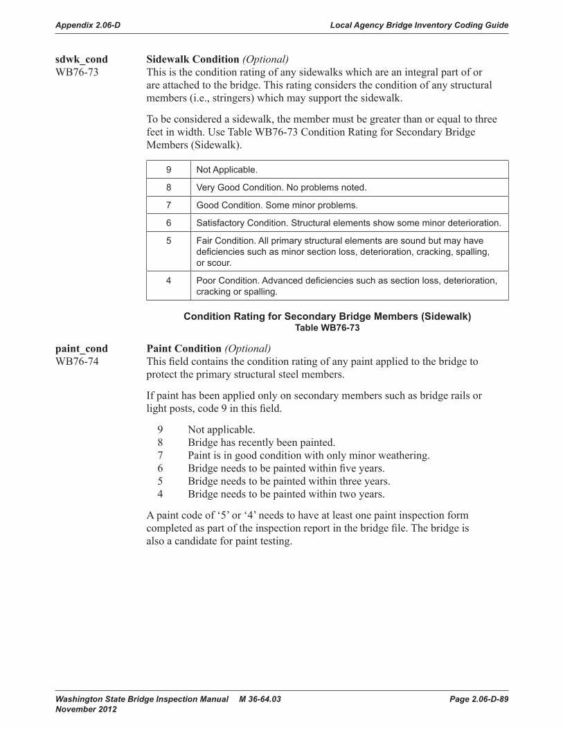
Appendix 2.06-D Local Agency Bridge Inventory Coding Guide
Washington State Bridge Inspection Manual M 36-64.03 Page 2.06-D-89 November 2012
sdwk_cond Sidewalk Condition (Optional)WB76-73 This is the condition rating of any sidewalks which are an integral part of or
are attached to the bridge. This rating considers the condition of any structural members (i.e., stringers) which may support the sidewalk.
To be considered a sidewalk, the member must be greater than or equal to three feet in width. Use Table WB76-73 Condition Rating for Secondary Bridge Members (Sidewalk).
9 Not Applicable.
8 Very Good Condition. No problems noted.
7 Good Condition. Some minor problems.
6 Satisfactory Condition. Structural elements show some minor deterioration.
5 Fair Condition. All primary structural elements are sound but may have deficiencies such as minor section loss, deterioration, cracking, spalling, or scour.
4 Poor Condition. Advanced deficiencies such as section loss, deterioration, cracking or spalling.
Condition Rating for Secondary Bridge Members (Sidewalk)Table WB76-73
paint_cond Paint Condition (Optional)WB76-74 This field contains the condition rating of any paint applied to the bridge to
protect the primary structural steel members.
If paint has been applied only on secondary members such as bridge rails or light posts, code 9 in this field.
9 Not applicable. 8 Bridge has recently been painted. 7 Paint is in good condition with only minor weathering. 6 Bridge needs to be painted within five years. 5 Bridge needs to be painted within three years. 4 Bridge needs to be painted within two years.
A paint code of ‘5’ or ‘4’ needs to have at least one paint inspection form completed as part of the inspection report in the bridge file. The bridge is also a candidate for paint testing.

Local Agency Bridge Inventory Coding Guide Appendix 2.06-D
Page 2.06-D-90 Washington State Bridge Inspection Manual M 36-64.03 November 2012
utilities_qty Number of Utilities (Optional)WB76-75 This field indicates the number of franchise utilities attached to the bridge.
Utilities include — but are not limited to — water pipes, sewer lines, telephone lines, power lines, and gas lines. Conduit for electricity used on the bridge is not considered a utility. A conduit cluster (i.e., a telephone cluster) is considered one utility.
This field is not used to evaluate the condition of utilities on the bridge, only the number of utilities present.
If more than nine utilities are attached to the bridge, code 9. If there are no utilities, code Ø. If the number of utilities is not known, leave this field blank.
substructure_cond Substructure Condition (Required)WB76-76FHWA Item 060 This item describes the overall physical condition of piers, abutments, piles,
fenders, footings, or other components. Rate and code the condition in accordance with the previously described general condition ratings. Code 9 for all culverts. BMS will address local conditions (see Chapter 4).
The condition of secondary members such as bracing, diaphragms, bearings, joints, paint system, etc., shall not be included in this rating, except in extreme situations, but should be noted on the inspection form.
The Substructure Condition code should be consistent with Scour code WB76-80. A Scour code of 2 or below should result in a corresponding Substructure code of 2 or below.
The substructure condition rating shall be made independent of the deck and superstructure.
Integral-abutment wing walls to the first construction or expansion joint shall be included in the evaluation. For non-integral superstructure and substructure units, the substructure shall be considered as the portion below the bearings.

Appendix 2.06-D Local Agency Bridge Inventory Coding Guide
Washington State Bridge Inspection Manual M 36-64.03 Page 2.06-D-91 November 2012
Use Table WB76-76 Condition Rating for Primary Bridge Members (Substructure).
9 Not Applicable.
8 Very Good Condition. No problems noted.
7 Good Condition. Some minor problems.
6 Satisfactory Condition. Structural elements show some minor deterioration.
5 Fair Condition. All primary structural elements are sound but may have deficiencies such as minor section loss, deterioration, cracking, spalling, or scour.
4 Poor Condition. Advanced deficiencies such as section loss, deterioration, cracking, spalling, or scour.
3 Serious Condition. Loss of section, deterioration, spalling, or scour have seriously affected primary structural components. Local failures are possible. Fatigue cracks in steel or shear cracks in concrete may be present.
2 Critical Condition. Advanced deterioration of primary structural elements. Fatigue cracks in steel or shear cracks in concrete maybe present or scour may have removed substructure support. Unless closely monitored, it may be necessary to close the bridge until corrective action is taken.
1 Imminent Failure Condition. Major deterioration or section loss present in critical structural components or obvious vertical or horizontal movement affecting structure stability. Bridge is closed to traffic but corrective action may put back in light service.
Ø Failed Condition. Out of service. Beyond corrective action.
Condition Rating for Primary Bridge Members (Substructure)Table WB76-76
channel_prot Channel Protection (Required)WB76-77FHWA Item 061 This item describes the physical conditions associated with the flow of water
beneath the bridge such as stream stability and the condition of the channel, riprap, slope protection, or stream control devices including spur dikes. The inspector should be particularly concerned with visible signs of excessive water velocity which may affect undermining of slope protection, erosion of banks, and realignment of the stream which may result in immediate or potential problems. Accumulation of drift and debris on the superstructure and substructure should be noted on the inspection form but not included in the condition rating.
If more than one condition is present, enter the lowest of the codes that apply. Use Table WB76-77.

Local Agency Bridge Inventory Coding Guide Appendix 2.06-D
Page 2.06-D-92 Washington State Bridge Inspection Manual M 36-64.03 November 2012
Code Devices Description
9 Bridge is not over a waterway.
8 Protected, well vegetated banks. No river control devices required or they are in stable condition.
7 Bank protection needs minor repair. River control devices/slope protection show minor damage. Banks and/or channel show minor accumulation of drift.
6 Bank beginning to slump. River control devices/slope protection show wide spread damage. Minor movement of streambed. Debris restricts waterway.
5 Eroded bank protection. River control devices/slope protection have major damage. Trees and brush restrict waterway.
4 Banks severely undermined. River control devices/slope protection have severe damage. Large deposits of debris in waterway.
3 Failed bank protection. River control devices are destroyed. Waterway has changed course so it now threatens the bridge and/or approach roadway.
2 Waterway has changed course to extent that bridge is now near collapse.
1 Bridge closed – may be able to be repaired.
0 Bridge closed – beyond repair.
Rating for Channel and Channel ProtectionTable WB76-77
culvert_cond Culvert Condition (Required)WB76-78FHWA Item 062 This is the general overall condition rating of any bridge which is a culvert.
A culvert is defined in the FHWA Culvert Inspection Manual as a drainage opening beneath an embankment, usually a pipe, which has been designed to allow the even flow of water beneath a roadway and designed to take advantage of submergence. This is a bridge with WB75-33 coded 19.
If the bridge is not a culvert, code 9 in this field.
Any culvert with a clear opening of more than 20 feet when measured along the center of the roadway, must be inventoried. In addition, any multiple pipes with a total span of more than 20 feet and a clear distance between openings of less than half of the smaller contiguous opening must also be inventoried. Culverts or multiple pipes which measure less than 20 feet may be inventoried at the agency’s discretion.

Appendix 2.06-D Local Agency Bridge Inventory Coding Guide
Washington State Bridge Inspection Manual M 36-64.03 Page 2.06-D-93 November 2012
When rating the general condition of the culvert, evaluate the alignment, degree of settlement, and structural integrity. Wingwalls which have been poured integral to the culvert’s first construction or expansion joint should be included in this evaluation. Refer to the FHWA Culvert Inspection Manual for a detailed discussion regarding the inspection and rating of culverts. See Figure WB76-78 and Table WB76-78A Rating for Concrete Culverts or Table WB76-78B Rating for Metal Culverts.
When culvert condition is coded (not including 9), code the following fields a 9.
Type Field Name WSBIS FHWA Item
Reqd. Overall Deck Dondition WB76-63 058
Reqd. Superstructure Overall WB76-71 059
Reqd. Substructure Condition WB76-76 060
Table WB76-78

Local Agency Bridge Inventory Coding Guide Appendix 2.06-D
Page 2.06-D-94 Washington State Bridge Inspection Manual M 36-64.03 November 2012
Bridge Inventory Coding Guide
Page 2-100 Washington State Bridge Inspection ManualJanuary 2002
Figure WB76 - 78
Figure WB76-78

Appendix 2.06-D Local Agency Bridge Inventory Coding Guide
Washington State Bridge Inspection Manual M 36-64.03 Page 2.06-D-95 November 2012
Code Description
9 Bridge is not a culvert.
8 No noticeable or noteworthy defects.
7 Cracking, light scaling and spalling which does not expose reinforcing steel. Minor damage from drift. Insignificant scouring near wingwalls or pipes.
6 Minor deterioration, chloride contamination cracking, leaching, or spalling. Minor scouring near wingwalls or pipes.
5 Moderate to major deterioration, cracking, leaching or spalling. Minor settlement or misalignment. Moderate scouring or erosion at wingwalls or pipes.
4 Major deterioration (large spalls, heavy scaling, wide cracks, open construction joints, etc). Considerable settlement or misalignment. Considerable scouring or erosion at wingwalls or pipes.
3 Extensive deterioration. Severe movement, differential settlement of segments, loss of fill. Holes in walls or slab. Wingwalls nearly severed. Severe scouring or erosion at wingwalls or pipes.
2 Collapsed wingwalls, severe settlement of roadway due to loss of fill. Section failure of culvert. Complete undermining at wingwalls or pipes.
1 Bridge closed – culvert may be able to be repaired.
Ø Bridge closed – culvert beyond repair.
Rating for Concrete CulvertsTable WB76-78A

Local Agency Bridge Inventory Coding Guide Appendix 2.06-D
Page 2.06-D-96 Washington State Bridge Inspection Manual M 36-64.03 November 2012
Code Description
9 Bridge is not a culvert
8 No noticeable or noteworthy defects. Bolts are in good condition, in place, and tight.
7 Smooth, symmetrical curvature with superficial corrosion and no pitting. Bolts may have superficial corrosion, are in place and tight.
6 Smooth curvature, non-symmetrical shape, and significant corrosion or moderate pitting. Bolts may have significant corrosion and 10 percent of the bolts in a panel seam maybe missing or loose.
5 Significant distortion and deflection in one section. Significant corrosion or deep pitting. Bolts may have significant corrosion and 20 percent of the bolts in a panel seam maybe missing or loose.
4 Significant distortion and deflection throughout. Extensive corrosion or deep pitting. Bolts may have extensive corrosion and 30 percent of the bolts in a panel seam maybe missing or loose.
3 Extreme distortion and deflection in one section. Extensive corrosion or deep pitting with scattered perforations. Bolts may have extensive corrosion and 40 percent of the bolts in a panel seam maybe missing or loose.
2 Extreme distortion and deflection in one section. Extensive perforations due to corrosion. Bolts may have extensive corrosion and 50 percent of the bolts in a panel seam maybe missing or loose.
1 Bridge closed – culvert may be able to be repaired.
Ø Bridge closed – culvert beyond repair.
Rating for Metal CulvertsTable WB76-78B

Appendix 2.06-D Local Agency Bridge Inventory Coding Guide
Washington State Bridge Inspection Manual M 36-64.03 Page 2.06-D-97 November 2012
Code Description
9 Bridge is not a culvert
8 No noticeable or noteworthy defects
7 Insignificant deterioration, decay or scour. No structural loss.
6 Minor deterioration, decay or scour. All primary structural elements are sound.
5 Moderate deterioration, decay or scour. All primary structural elements are sound but have some section loss.
4 Major deterioration, decay or scour. Advanced section loss or scour that affects the load capacity of the structure.
3 Extensive deterioration, decay or scour. Advanced section loss or scour that significantly affects the load capacity of the structure.
2 Severe deterioration, decay or scour. Critical structural members have obvious vertical or horizontal movement affecting structural stability.
1 Bridge closed – culvert may be able to be repaired.
Ø Bridge closed – culvert beyond repair.
Rating for Timber CulvertsTable WB76-78C
pier_abutment_prot Pier / Abutment Protection (Required)WB76-79FHWA Item 111 This is only required If the bridge crosses a navigable channel (Item 386 = 1).
This item contains a code which indicates the presence and adequacy of pier and/or abutment navigation protection features (i.e., fenders and dolphins).
WB76-79 evaluates the adequacy of the pier protection features and is not an evaluation of their general condition. WB76-83 is to be used for rating their general condition. However, the adequacy evaluation of these features should correspond to condition ratings entered in WB76-83 in the manner noted.
If WB73-86 has not been coded 1, code N in this field.
1 No pier protection is required. 2 Pier protection is in place and functioning properly (it has a condition rating of 6, 7, or 8). 3 Pier protection is in place but is in a deteriorating condition (it has a condition rating of 4 or 5), 4 Pier protection is in place but a reevaluation of its design is needed. 5 No pier protection is present but a reevaluation of the need for it should be made. N Not applicable.

Local Agency Bridge Inventory Coding Guide Appendix 2.06-D
Page 2.06-D-98 Washington State Bridge Inspection Manual M 36-64.03 November 2012
scour_ Scour (Required)WB76-80FHWA Item 113 This rating is used to identify the current status of a bridge regarding its
vulnerability to scour. Details on conducting a scour analysis are included in Chapter 5. Whenever a rating factor of 4 or below is determined for this item, the rating factor for WB76-76, Substructure may need to be revised to reflect the severity of actual scour and resultant damage to the bridge. A scour critical bridge is one with abutment or pier foundations which are rated as unstable due to (1) observed scour at the bridge site or (2) a scour potential as determined from a scour evaluation study.
When a bridge inspector identifies an actual or potential scour problem, the bridge must be further evaluated to determine whether or not it should be considered scour critical. This evaluation process includes field observations by an individual (or individuals) with a knowledge of foundation, hydraulic, and geotechnical engineering and may require that calculations of anticipated scour depths be made.
See Figure WB76-80 and Table WB76-80 Rating for Scour.

Appendix 2.06-D Local Agency Bridge Inventory Coding Guide
Washington State Bridge Inspection Manual M 36-64.03 Page 2.06-D-99 November 2012
Bridge Inventory Coding Guide
Page 2-106 Washington State Bridge Inspection ManualJanuary 2002
Figure WB76 - 80
Figure WB76-80

Local Agency Bridge Inventory Coding Guide Appendix 2.06-D
Page 2.06-D-100 Washington State Bridge Inspection Manual M 36-64.03 November 2012
Code Description
N Bridge is not over a waterway.
U Bridge with “unknown” foundation that has not been evaluated for scour. Until risk can be determined, a plan of action should be developed and implemented to reduce the risk to users from a bridge failure during and immediately after a flood event (see HEC 23).
T Bridge over “tidal” waters that has not been evaluated for scour, but considered low risk. Bridge will be monitored with regular inspection cycle and with appropriate underwater inspections until an evaluation is performed (“Unknown” foundations in “tidal” waters should be coded U.)
9 Bridge foundations (including piles) well above flood water elevations.
8 Bridge foundations determined to be stable for the assessed or calculated scour condition. Scour is determined to be above top of footing (Example A) by assessment (i.e., bridge foundations are on rock formations that have been determined to resist scour within the service life of the bridge4), by calculation or by installation of properly designed countermeasures (see HEC 23).
7 Countermeasures have been installed to mitigate an existing problem with scour and to reduce the risk of bridge failure during a flood event. Instructions contained in a plan of action have been implemented to reduce the risk to users from a bridge failure during or immediately after a flood event.
6 Scour calculation/evaluation has not been made.
5 Bridge foundations determined to be stable for assessed or calculated scour condition. Scour is determined to be within the limits of footing or piles (Example B) by assessment (i.e., bridge foundations are on rock formations that have been determined to resist scour within the service life of the bridge), by calculations or by installation of properly designed countermeasures (see HEC 23).
4 Bridge foundations determined to be stable for assessed or calculated scour conditions; field review indicates action is required to protect exposed foundations (see HEC 23).
3 Bridge is scour critical; bridge foundations determined to be unstable for assessed or calculated scour conditions: • Scour within limits of footing or piles (see Figure WB76-80B). • Scour below spread-footing base or pile tips (see Figure WB76-80C).
2 Bridge is scour critical; field review indicates that extensive scour has occurred at bridge foundations, which are determined to be unstable by: • A comparison of calculated scour and observed scour during the bridge inspection, or • An engineering evaluation of the observed scour condition reported by the bridge inspector in WB76-76.
1 Bridge is scour critical; field review indicates that failure of piers/abutments is imminent. Bridge is closed to traffic. Failure is imminent based on: • A comparison of calculated and observed scour during the bridge inspection, or • An engineering evaluation of the observed scour condition reported by the bridge inspector in WB76-76.
Ø Bridge is scour critical. Bridge has failed and is closed to traffic.
Rating for ScourTable WB76-80
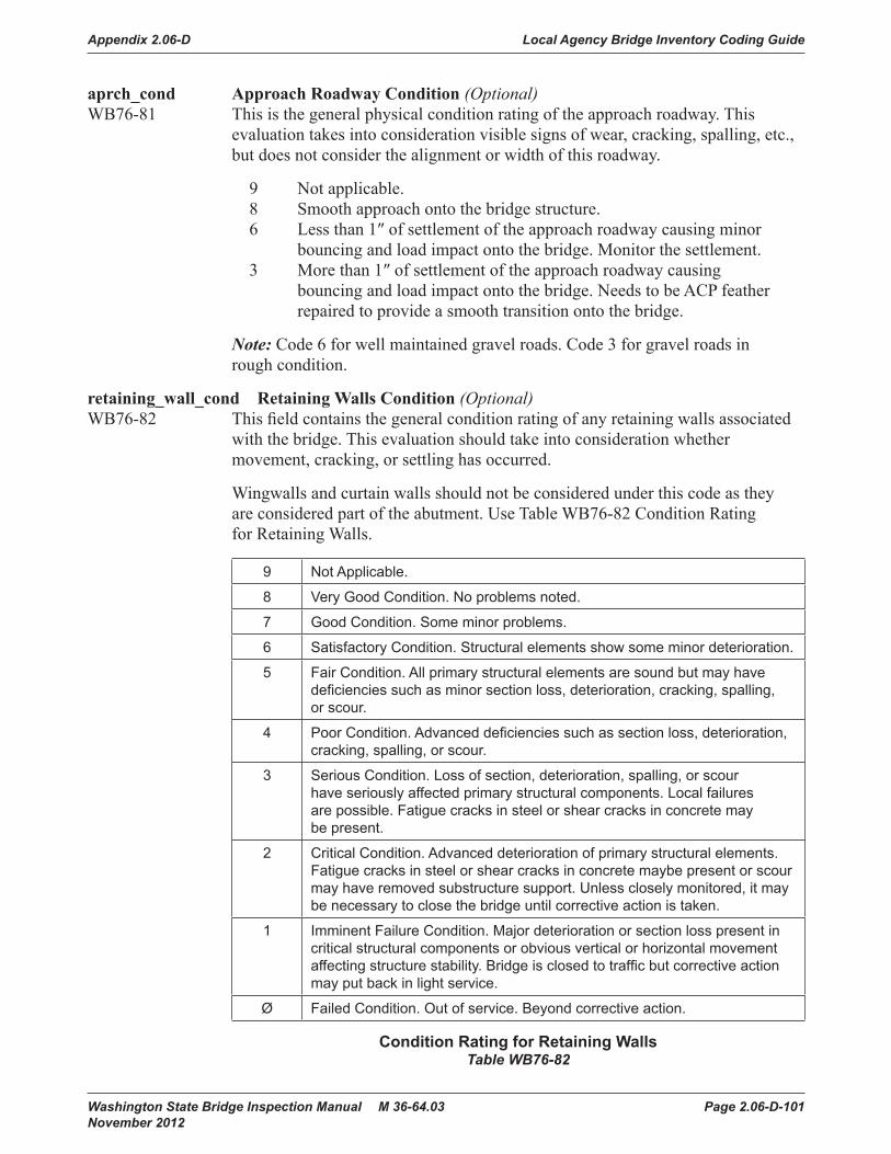
Appendix 2.06-D Local Agency Bridge Inventory Coding Guide
Washington State Bridge Inspection Manual M 36-64.03 Page 2.06-D-101 November 2012
aprch_cond Approach Roadway Condition (Optional)WB76-81 This is the general physical condition rating of the approach roadway. This
evaluation takes into consideration visible signs of wear, cracking, spalling, etc., but does not consider the alignment or width of this roadway.
9 Not applicable. 8 Smooth approach onto the bridge structure. 6 Less than 1″ of settlement of the approach roadway causing minor bouncing and load impact onto the bridge. Monitor the settlement. 3 More than 1″ of settlement of the approach roadway causing bouncing and load impact onto the bridge. Needs to be ACP feather repaired to provide a smooth transition onto the bridge.
Note: Code 6 for well maintained gravel roads. Code 3 for gravel roads in rough condition.
retaining_wall_cond Retaining Walls Condition (Optional)WB76-82 This field contains the general condition rating of any retaining walls associated
with the bridge. This evaluation should take into consideration whether movement, cracking, or settling has occurred.
Wingwalls and curtain walls should not be considered under this code as they are considered part of the abutment. Use Table WB76-82 Condition Rating for Retaining Walls.
9 Not Applicable.
8 Very Good Condition. No problems noted.
7 Good Condition. Some minor problems.
6 Satisfactory Condition. Structural elements show some minor deterioration.
5 Fair Condition. All primary structural elements are sound but may have deficiencies such as minor section loss, deterioration, cracking, spalling, or scour.
4 Poor Condition. Advanced deficiencies such as section loss, deterioration, cracking, spalling, or scour.
3 Serious Condition. Loss of section, deterioration, spalling, or scour have seriously affected primary structural components. Local failures are possible. Fatigue cracks in steel or shear cracks in concrete may be present.
2 Critical Condition. Advanced deterioration of primary structural elements. Fatigue cracks in steel or shear cracks in concrete maybe present or scour may have removed substructure support. Unless closely monitored, it may be necessary to close the bridge until corrective action is taken.
1 Imminent Failure Condition. Major deterioration or section loss present in critical structural components or obvious vertical or horizontal movement affecting structure stability. Bridge is closed to traffic but corrective action may put back in light service.
Ø Failed Condition. Out of service. Beyond corrective action.
Condition Rating for Retaining WallsTable WB76-82

Local Agency Bridge Inventory Coding Guide Appendix 2.06-D
Page 2.06-D-102 Washington State Bridge Inspection Manual M 36-64.03 November 2012
pier_prot Pier Protection Condition (Optional)WB76-83 This rating describes the general condition rating of any pier and/or abutment
protection features (i.e., fenders and dolphins) which have been put in place to protect the bridge against collisions from vessels or objects in tow.
This field is used for rating the general condition of the bridge’s pier protection features and does not evaluate the adequacy of those features.
If no pier protection exists, code 9. Use Table WB76-83 Condition Rating for Secondary Bridge Members (Pier Protection).
9 Not Applicable.
8 Very Good Condition. No problems noted.
7 Good Condition. Some minor problems.
6 Satisfactory Condition. Structural elements show some minor deterioration.
5 Fair Condition. All primary structural elements are sound but may have deficiencies such as minor section loss, deterioration, cracking, spalling, or scour.
4 Poor Condition. Advanced deficiencies such as section loss, deterioration, cracking, spalling, or scour.
Condition Rating for Secondary Bridge Members (Pier Protection)Table WB76-83
bridge_rail_adqcy Traffic Safety, Bridge Rails (Required)WB76-84FHWA Item 036A This code indicates whether or not the bridge railings meet current design
standards as established by the AASHTO Standards Specifications for Highway Bridges. To meet current design standards, bridge railings must be capable of smoothly redirecting an impacting vehicle and meet current crash test standards. Factors which may affect this capability are bridge rail height, strength, type of material, and geometric design. See Figure WB76-84.
0 Does not meet currently acceptable standards or a feature is required but not provided. 1 Meets currently acceptable standards. N Not applicable, or not required, such as a non-vehicular bridge.

Appendix 2.06-D Local Agency Bridge Inventory Coding Guide
Washington State Bridge Inspection Manual M 36-64.03 Page 2.06-D-103 November 2012
rail_trans_adqcy Traffic Safety, Transitions (Required)WB76-85FHWA Item 036B This rating indicates whether or not the transition between the bridge rail and
the approach guardrail meets current design standards. See Figure WB76-87. To meet design standards, the transition must provide for the following:
• A gradual stiffening of the approach guardrail in a manner that will not cause sagging or pocketing due to vehicle impact.
• A firm attachment between the approach guardrail and the bridge by a WSDOT Type F anchor, a WSDOT Type 3 beam guardrail anchor, or extension of the concrete barrier.
• A gradual tapering out of the curb ends.
0 Does not meet currently acceptable standards or a feature is required but not provided. 1 Meets currently acceptable standards. N Not applicable, or not required, such as a non-vehicular bridge.
aprch_rail_adqcy Traffic Safety, Guardrails (Required)WB76-86FHWA Item 036C This rating indicates whether or not the approach guardrail meets current
design standards. To meet standards, the approach guardrail should be of adequate length, height, and structural quality to shield motorists from bridge ends or from other hazards at the bridge site. Design standards are given in the AASHTO Roadside Design Guide. See Figure WB76-87.
Ø Does not meet currently acceptable standards or a feature is required but not provided. 1 Meets currently acceptable standards. N Not applicable, or not required, such as a non-vehicular bridge.
rail_end_adqcy Traffic Safety, Terminals (Required)WB76-87FHWA Item 036D This code indicates whether or not the terminals (guardrail ends) meet current
design standards. To meet standards, the terminals should either be flared, buried, shielded, or able to break away. Design standards for terminals are given in the AASHTO Roadside Design Guide. See Figure WB76-87.
Ø Does not meet currently acceptable standards or a feature is required but not provided. 1 Meets currently acceptable standards. N Not applicable, or not required, such as a non-vehicular bridge.

Local Agency Bridge Inventory Coding Guide Appendix 2.06-D
Page 2.06-D-104 Washington State Bridge Inspection Manual M 36-64.03 November 2012
Washington State Bridge Inspection Manual Page 2-113January 2002
Bridge Inventory Coding Guide
Approach Rail RequirementsFigures WB76 - 84 through WB76 - 87
2 way roadway4 lanes or less
Approach guardrail requiredwhere shown (Typ.)
2 way roadway5 lanes or more
NOTES:
A. Approach guardrail required at allcorners for reversible lane bridges.
B. Approach guardrail may not be
Divided highways
required if the bridge is in an urbanarea with sidewalks continuing wellbeyond the bridge ends.
Guardrailterminal
Approach guardrail
Curb face extension line
TransitionBridge
rail
APPROACH RAIL REQUIREMENTS
Bridgeend
Note: See Standard Plans Section C for current standards.
Approach Rail RequirementsFigures WB76-84 through WB76-87

Appendix 2.06-D Local Agency Bridge Inventory Coding Guide
Washington State Bridge Inspection Manual M 36-64.03 Page 2.06-D-105 November 2012
rating_calc_ Rating (Optional)WB76-88 This code indicates whether or not the load ratings WB75-52 and WB75-55 need
to be reviewed or calculated.
Y Yes, operating and/or inventory ratings need to be reviewed, or original ratings need to be established. N No, operating and/or inventory ratings need not be reviewed.
repair_status_ Repair Status (Optional)WB76-89 The inspector should code this field Y If there are recommended repairs.
Y Recommended repair add to Bridge Repair List items. N No Recommended Repairs.
card_check_ Card Check (Optional)WB76-90 This field indicates that a Kardex card check is required as part of this inspection.
This is either a new or rebuilt bridge. Used by WSDOT personnel only.
Y Yes, perform a card check as part of this inspection. N No, do not perform a card check.
inspn_photo_ Photographs (Optional)WB76-91 This code identifies the types of photographs to be taken during this inspection.
D Take deck photographs. E Take elevation photographs. P Take both deck and elevation photographs.
Leave this field blank If photographs are not required. Use an asterisk to remove a code.
inspn_season_ Season (Optional)WB76-92 This field specifies the time of year in which this bridge should be inspected,
either summer, winter, or another seasonal inspection.
L During low water S Summer W Winter B Outside bird nesting season F Outside fish windows K Call for utility
Use an asterisk to remove a code.
inspn_soundings_ Soundings (Optional)WB76-93 This code indicates whether or not soundings of the streambed are required.
Y Soundings should be taken. N Soundings need not be taken.

Local Agency Bridge Inventory Coding Guide Appendix 2.06-D
Page 2.06-D-106 Washington State Bridge Inspection Manual M 36-64.03 November 2012
measure_clrnc_ Clearances (Optional)WB76-94 This field identifies which clearances need to be checked on a bridge.
C Measure both horizontal and vertical clearances. H Measure horizontal clearances. V Measure vertical clearances.
Leave this field blank If clearances are not required. Use an asterisk to remove a code.
monitor_structure_ Monitor Structure (Optional)WB76-95 This field prompts the inspector to review comments from the previous
inspection to identify what to monitor during an inspection.
Y Yes N No

Appendix 2.06-D Local Agency Bridge Inventory Coding Guide
Washington State Bridge Inspection Manual M 36-64.03 Page 2.06-D-107 November 2012
inspn_fracture_type Fracture Critical/UBIT Inspection, Type (Required)WB77-32FHWA Item 92A Code If a fracture critical inspection is required or whether an Under Bridge
Inspection Truck (UBIT) is needed.
U A Fracture Critical inspection is required (using a UBIT). Y A Fracture Critical inspection is required (without using a UBIT). I Requires UBIT for inspection, not Fracture Critical. N No Fracture Critical inspection is required.
fracture_inspn_freq Fracture Critical/UBIT Inspection, Frequency (Required)WB77-33FHWA Item 92A A two-digit code representing the number of months between consecutive
fracture critical or UBIT inspections.
fracture_inspn_date Fracture Critical/UBIT Inspection Last Inspection Date (Fatal)WB77-35FHWA Item 93A The date on which the most recent fracture critical inspection was completed.
Code this field in the mmddyyyy format.
fracture_inspn_hours Fracture Critical/UBIT Inspection Hours (Required)WB77-43 The total number of inspection hours (to the nearest tenth of an hour) that the
inspection team spent on the bridge during the most recent fracture critical/UBIT inspection. Use leading zeros.
fracture_inspr_initials Fracture Critical/UBIT Inspection Inspector (Optional)WB77-47 The initials of the lead inspector of the inspection team who performed the most
recent fracture critical/UBIT inspection.
fracture_cert_no Fracture Critical/UBIT Inspector Identification No (Fatal)WB77-50 The certification number of the lead inspector at the bridge site during the most
recent fracture critical /UBIT inspection.
fracture_co_inspr_initials Fracture Critical/UBIT Co-Inspector (Optional)WB77-55 The initials of the individual who assisted the lead inspector in performing the
most recent fracture critical /UBIT inspection.
inspn_underwater_type Underwater Inspection, Type (Required)WB77-58FHWA Item 92B The type of underwater inspection that is required for the bridge.
D Underwater inspection with a diver (and fathometer, If necessary) is required. N No underwater inspection is required. O Other type of underwater inspection is required (submarine, ROV, etc.). W Underwater inspection w/o diver (wading) is required.

Local Agency Bridge Inventory Coding Guide Appendix 2.06-D
Page 2.06-D-108 Washington State Bridge Inspection Manual M 36-64.03 November 2012
underwater_inspn_freq Underwater Inspection, Frequency (Required)WB77-59FHWA Item 92B A two-digit code representing the number of months between consecutive
underwater inspections.
underwater_inspn_date Underwater Inspection Last Inspection Date (Fatal)WB77-61FHWA Item 93B The date on which the most recent underwater inspection was completed.
Code this field in the mmddyyyy format.
underwater_inspn_hours Underwater Inspection Hours (Optional)WB77-69 The total number of inspection hours (to the nearest tenth of an hour) that the
inspection team spent at the bridge during the most recent underwater inspection. Use leading zeros.
underwater_inspr_initials Underwater Inspection Inspector (Required)WB77-73 The initials of the lead inspector of the inspection team who performed the most
recent underwater inspection.
underwater_cert_no Underwater Inspection Inspector Identification No (Fatal)WB77-76 The certification number of the lead inspector at the bridge site during the most
recent underwater inspection.
underwater_co_inspr_initials Underwater Inspection Co-Inspector (Optional)WB77-81 The initials of the individual who assisted the lead inspector in performing the
most recent underwater inspection.
inspn_special_type Other Special Inspections, Type (Required)WB77-84FHWA Item 92C This field identifies the type of special inspection that is required for the bridge.
1 Movable bridge. 2 Floating bridge. 3 Suspension bridge. 4 Redundant pin/hanger bridge. 5 Segmental. 6 Ferry terminal. 7 High strength steel bridge. 8 Bridges with temporary supports (require intermediate inspections). 9 Cable stayed. Ø Other special features. N No special inspection is required.
special_inspn_freq Special Inspection Frequency (Required)WB77-85FHWA Item 92C A two-digit code representing the number of months between consecutive
special inspections.
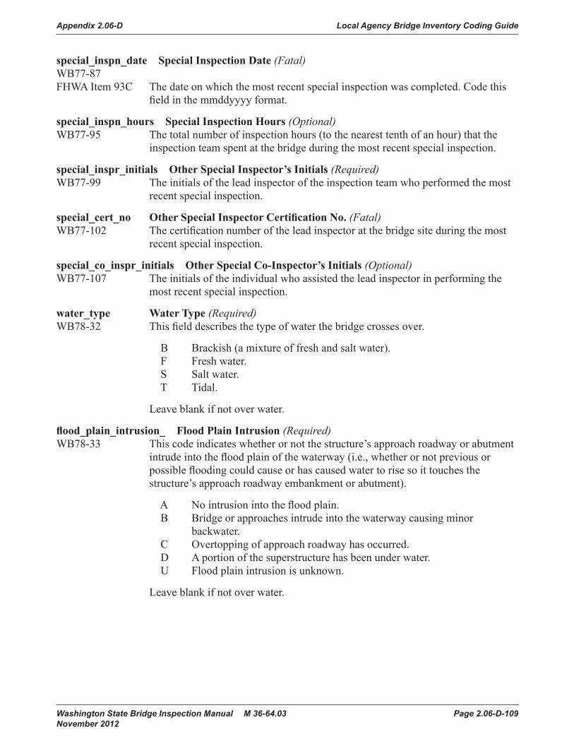
Appendix 2.06-D Local Agency Bridge Inventory Coding Guide
Washington State Bridge Inspection Manual M 36-64.03 Page 2.06-D-109 November 2012
special_inspn_date Special Inspection Date (Fatal)WB77-87FHWA Item 93C The date on which the most recent special inspection was completed. Code this
field in the mmddyyyy format.
special_inspn_hours Special Inspection Hours (Optional)WB77-95 The total number of inspection hours (to the nearest tenth of an hour) that the
inspection team spent at the bridge during the most recent special inspection.
special_inspr_initials Other Special Inspector’s Initials (Required)WB77-99 The initials of the lead inspector of the inspection team who performed the most
recent special inspection.
special_cert_no Other Special Inspector Certification No. (Fatal)WB77-102 The certification number of the lead inspector at the bridge site during the most
recent special inspection.
special_co_inspr_initials Other Special Co-Inspector’s Initials (Optional)WB77-107 The initials of the individual who assisted the lead inspector in performing the
most recent special inspection.
water_type Water Type (Required)WB78-32 This field describes the type of water the bridge crosses over.
B Brackish (a mixture of fresh and salt water). F Fresh water. S Salt water. T Tidal.
Leave blank if not over water.
flood_plain_intrusion_ Flood Plain Intrusion (Required)WB78-33 This code indicates whether or not the structure’s approach roadway or abutment
intrude into the flood plain of the waterway (i.e., whether or not previous or possible flooding could cause or has caused water to rise so it touches the structure’s approach roadway embankment or abutment).
A No intrusion into the flood plain. B Bridge or approaches intrude into the waterway causing minor backwater. C Overtopping of approach roadway has occurred. D A portion of the superstructure has been under water. U Flood plain intrusion is unknown.
Leave blank if not over water.

Local Agency Bridge Inventory Coding Guide Appendix 2.06-D
Page 2.06-D-110 Washington State Bridge Inspection Manual M 36-64.03 November 2012
flood_control_ Flood Control (Required)WB78-34 This field indicates If there is any existing type of flood control on the waterway
the bridge crosses. To be considered, this flood control must be in place either upstream or downstream from the bridge and must be near enough to have an effect on the bridge. Flood control may be provided by dams, dikes, fill, or other means.
B Both upstream and downstream. U Upstream. D Downstream. N No flood control.
Leave blank if not over water.
scour_history_ Scour History (Required)WB78-35 This code describes scour conditions at the bridge site.
C Current scour problems. H History of scour problems but scour conditions are now stable. N No history of scour. U Scour history is unknown.
Leave blank if not over water.
streambed_material_type Streambed Material Type (Required)WB78-36 This code describes the composition of the streambed at the bridge site. Enter one of the following codes to indicate the predominant type of material
that is evident.
1 Bedrock 2 Sediment 3 Gravel 4 Sand 5 Cobbles 6 Lined Canal 7 Vegetation 8 Alluvial Fan 9 Unknown
Leave blank if not over water.

Appendix 2.06-D Local Agency Bridge Inventory Coding Guide
Washington State Bridge Inspection Manual M 36-64.03 Page 2.06-D-111 November 2012
substructure_stability_ Substructure Stability (Required)WB78-37 This code describes the type of material upon which the bridge’s substructure
rests. This code is used to determine the degree of stability that can be expected in the bridge substructure.
Code the lower number value If different sections of a continuous span bridge are supported by different materials.
1 Spread footing, simple spans. 2 Spread footing, continuous spans. 3 Pile foundation, simple spans. 4 Pile foundation, continuous spans. 5 Bedrock, simple spans. 6 Bedrock, continuous spans. 7 Unknown, simple spans. 8 Unknown, continuous spans
Leave blank if not over water.
waterway_obstruction Waterway Obstruction (Required)WB78-38 This code indicates any conditions in the waterway which affect the flow of water
beneath the bridge.
A Debris accumulates at the bridge. B Ice accumulates at the bridge. C The waterway is overgrown with vegetation. D A and C above. E A and B above. F B and C above. G A, B, and C above. N No obstruction to the flow of water beneath the bridge.
Leave blank if not over water.
streambed_stability_ Streambed Stability (Required)WB78-39 This code describes any existing stream conditions which may influence scour
at the bridge site.
A Sharp bends. B Significant lateral shifts. C Steep slopes. D High water velocity. E Degradation. F Aggredation. G No conditions influencing scour exist. H Streambed conditions are unknown.
Leave blank if not over water.

Local Agency Bridge Inventory Coding Guide Appendix 2.06-D
Page 2.06-D-112 Washington State Bridge Inspection Manual M 36-64.03 November 2012
streambed_anabranch_ Streambed Anabranch (Required)WB78-40 This field indicates whether or not confluences or shifting anabranches are
present in the waterway. A confluence is a flowing together of two or more streams. An anabranch is a river branch that re-enters the main stream, creating an island in the waterway.
Code only those conditions which exist near the bridge site.
A Anabranches are present. B Both anabranches and confluences are present. C Confluences are present. N Neither anabranches nor confluences are present. U Waterway configuration is unknown.
Leave blank if not over water.
piers_in_waterway Piers in Water (Required)WB78-41 This field contains the number of the structure’s piers in the water at normal
yearly high water.
If the bridge is inspected at low water, look for evidence that the piers or pile bents have been in the water.
0 No piers in the water. 1-9 Number of piers in the water. M More than nine piers in the water.
Leave blank if not over water.
prpsed_serv_on_code Proposed Improvement Service On (Required)WB78-42 This field identifies the type of service to be carried on the proposed bridge.
1 Highway. 2 Railroad. 3 Pedestrian exclusively. 4 Highway and railroad. 5 Highway and pedestrian. 6 Overpass bridge at an interchange or second level of a multilevel interchange. 7 Third level of a multilevel interchange. 8 Fourth level of a multilevel interchange. 9 Building or plaza. 0 Other or Not Applicable.
The code Ø means “Other” only If there are proposed improvements. If there are no proposed improvements to the bridge, the code Ø means “not applicable.”

Appendix 2.06-D Local Agency Bridge Inventory Coding Guide
Washington State Bridge Inspection Manual M 36-64.03 Page 2.06-D-113 November 2012
prpsed_serv_under_code Proposed Improvement Service Under (Required)WB78-43 This field identifies the type of service under the proposed bridge.
1 Highway, with or without pedestrian traffic. 2 Railroad. 3 Pedestrians exclusively. 4 Highway and railroad. 5 Waterway. 6 Highway and waterway. 7 Railroad and waterway. 8 Highway, waterway, and railroad. 9 Relief. 0 Other or Not Applicable
The code 0 means “Other” only If there are proposed improvements. If there are no proposed improvements to the bridge, the code 0 means “not applicable.”
prpsed_work_type Proposed Improvement Work Type (Required)WB78-44FHWA Item 075A This field identifies the type of work to be accomplished on the proposed
improvement. The proposed work should improve the bridge to the degree that it can provide the type of service needed. This field must be coded for bridges eligible for the Highway Bridge Replacement and Rehabilitation Program. To be eligible, a bridge must carry highway traffic, be deficient and have a sufficiency rating of 80.0 or less.
31 Replacement of bridge because of substandard load-carrying capacity or substandard bridge roadway geometry. 32 Replacement of bridge because of relocation of road. 33 Widening of existing bridge without deck rehabilitation or replacement OR lengthening of a culvert. 34 Widening of existing bridge with deck rehabilitation or replacement. 35 Rehabilitation of bridge because of general structural deterioration or inadequate strength. 36 Rehabilitation of bridge deck with only incidental widening. 37 Replacement of bridge deck with only incidental widening. 38 Other structural work, includes hydraulic replacements. 00 If there are no proposed improvements to the bridge, the code 00 means “not applicable.”
If there are no proposed improvements to the bridge, the code 00 means “not applicable.”

Local Agency Bridge Inventory Coding Guide Appendix 2.06-D
Page 2.06-D-114 Washington State Bridge Inspection Manual M 36-64.03 November 2012
prpsed_work_meth Proposed Improvement Work Method (Required)WB78-46FHWA Item 075B This field indicates who will perform the work (as indicated in WB78-44)
on the proposed improvement.
1 Work to be done by contract. 2 Work to be done by the agency which owns the bridge.
prpsed_length Proposed Improvement Length (Required)WB78-47FHWA Item 76 This field contains the length of the proposed improvement. The measurement
is to the nearest foot. This should be a measurement of the proposed length of the bridge only, not the length of the project. (Do not include the length of approach guardrails.)
If only a portion of the bridge is to be rehabilitated or replaced, the improvement length is a measurement of the portion being improved only. If the entire bridge is being rehabilitated or replaced, the improvement length is measured from back to back of abutment backwalls or from pavement notch to pavement notch. See Figure WB78-47A.
If the bridge is a pipe or culvert, the improvement length is measured along the centerline of the barrel, regardless of pipe or culvert depth below grade. For pipes, code the total length of the pipe before ends have been mitered. This is not the length as is referenced in WB74-40. See Figure WB78-47B.
If the proposed improvement is to the substructure or channel beneath the bridge, code the length of the bridge directly over, or supported by, the substructure or channel.
This field must be coded for bridges eligible for the Highway Bridge Replacement and Rehabilitation Program.

Appendix 2.06-D Local Agency Bridge Inventory Coding Guide
Washington State Bridge Inspection Manual M 36-64.03 Page 2.06-D-115 November 2012Washington State Bridge Inspection Manual Page 2-125
January 2002
Bridge Inventory Coding Guide
Figure WB78 - 47A
/0 /0 /021 /0
/0 /0 /0 /064Figure WB78-47A

Local Agency Bridge Inventory Coding Guide Appendix 2.06-D
Page 2.06-D-116 Washington State Bridge Inspection Manual M 36-64.03 November 2012
Bridge Inventory Coding Guide
Page 2-126 Washington State Bridge Inspection ManualJanuary 2002
Figure WB78 - 47B
/0 /0 /0127
/0 /0 /0 /058
Figure WB78-47B

Appendix 2.06-D Local Agency Bridge Inventory Coding Guide
Washington State Bridge Inspection Manual M 36-64.03 Page 2.06-D-117 November 2012
prpsed_roadway_width Proposed Improvement Roadway Width (Required)WB78-53 This field contains the curb-to-curb width of the roadway on the proposed bridge.
This measurement is coded to the nearest foot.
prpsed_lanes_on Proposed Improvement Lanes On (Required)WB78-57 This field contains the number of through lanes the proposed bridge will carry.
prpsed_lanes_under Proposed Improvement Lanes Under (Required)WB78-59 This field contains the number of lanes that will pass beneath the proposed
bridge.
prpsed_total_cost Proposed Improvement Total Cost (Required)WB78-61FHWA Item 096 This field must be coded for bridges eligible for the Highway Bridge
Replacement and Rehabilitation Program. This field contains the total cost of the proposed improvements in thousands of dollars. This value includes the bridge cost, the roadway cost, and all incidental costs normally associated with the proposed bridge improvement project. The total project cost will, therefore, usually be greater than the sum of the bridge and roadway costs.
If WB78-83 is coded N, the cost will not be automatically generated.
If no improvement is needed, code all zeroes.
Do not use this field to estimate maintenance costs.
prpsed_structure_cost Proposed Improvement Structure Cost (Required)WB78-67FHWA Item 094 This field must be coded for bridges eligible for the Highway Bridge
Replacement and Rehabilitation Program. This field contains the estimated cost, in thousands of dollars, for the proposed bridge or major bridge improvements. This total should include only bridge construction costs.
It excludes any roadway, right of way, detour, demolition, preliminary engineering, maintenance, guardrail, or paving costs that are not part of the bridge cost.
If WB78-83 is coded N, the cost will not automatically be generated.
If no improvement is needed, code all zeroes.

Local Agency Bridge Inventory Coding Guide Appendix 2.06-D
Page 2.06-D-118 Washington State Bridge Inspection Manual M 36-64.03 November 2012
prpsed_roadway_cost Proposed Improvement Roadway Cost (Required)WB78-73FHWA Item 095 This field contains the estimated cost, in thousands of dollars, for any proposed
roadway improvements. This total includes all roadway construction costs, including guardrail and paving costs, but does not include bridge , right of way, detour, extensive roadway realignment, preliminary engineering, or maintenance costs.
If WB78-83 is coded N, the cost will not automatically be generated.
This field must be coded for bridges eligible for the Highway Bridge Replacement and Rehabilitation Program.
prpsed_estimate_year Proposed Improvement Estimate Year (Required)WB78-79FHWA Item 097 This field contains the year in which the project cost estimates have been made.
If this date is more than eight years old, the cost estimates entered in WB78-61, WB78-67, and WB78-73 must be revised and a new estimate year must be entered in this field.
prpsed_cost_calc_ Proposed Improvement Calculation (Required)WB78-83 This field directs the WSBIS system to compute costs for any proposed bridge
improvements.
If no improvements are proposed for the bridge, this field should be left blank.
Y Yes, compute the replacement costs automatically. N No, do not automatically compute the replacement costs.
inspn_agency_id Inspecting Agency (Optional)WB78-84 If the agency which owns the bridge does not have primary responsibility for
inspecting it, this field describes the type of agency inspecting the bridge.
If the owner agency has primary responsibility for inspecting the bridge, leave this field blank, otherwise enter a code to indicate the type of agency inspecting the bridge.
When the agency which owns the bridge performs routine inspections on it and uses other agencies to perform special inspections (for example, a consultant performs underwater inspections), the primary responsibility for inspecting the bridge is still considered to rest with the owner agency. The field should be left blank. Use the following codes.

Appendix 2.06-D Local Agency Bridge Inventory Coding Guide
Washington State Bridge Inspection Manual M 36-64.03 Page 2.06-D-119 November 2012
01 State Highway Agency 02 County Highway Agency 03 Town or Township Highway Agency 04 City or Municipal Highway Agency 11 State Park, Forest, or Reservation Agency 12 County Park, Forest, or Reservation Agency 13 City/Other Park, Forest, or Reservation Agency 21 Other State Agencies 24 Other County Agencies 25 Other City or Local Agencies 26 Private (Consultant) 27 Railroad 31 State Toll Authority 32 County Toll Authority 33 City or Other Toll Authority 60 Other Federal Agencies (not listed below) 61 Indian Tribal Government 62 Bureau of Indian Affairs 63 Bureau of Fish and Wildlife 64 U.S. Forest Service 66 National Park Service 68 Bureau of Land Management 69 Bureau of Reclamation 70 Corps of Engineers (Civilian) 71 Corps of Engineers (Military) 72 Air Force 73 Navy/Marines 74 Army 75 NASA 76 Metroplitan Washington Airport Services 80 Unknown 91 Canada 92 Idaho 93 Oregon

Local Agency Bridge Inventory Coding Guide Appendix 2.06-D
Page 2.06-D-120 Washington State Bridge Inspection Manual M 36-64.03 November 2012
city_inspn_no Inspecting Agency Number (Optional)WB78-86 If the agency which owns the bridge does not have primary responsibility
for inspecting it, this field contains a code which indicates the entity which is performing the inspections.
Use the following criteria for determining the proper code to enter:
1 If the inspecting entity is a county, code that county’s number in the first two field positions and leave the last two field positions blank.
2 If the inspecting agency is a city, code that city’s four-digit number in the field.
3 If the inspecting entity is WSDOT or an agency outside Washington State, code all zeroes in the field.
If the owner agency is inspecting the bridge, leave this field blank
seismic_superstrctr_main_b Seismic Status Superstructure Main Biennium (Optional)WB78-90 This field contains the biennium in which the superstructure main span group
was fitted with seismic restraining devices.
Enter the beginning and ending years of the biennium. For example, code the 1997-1999 biennium as 9799.
Leave this field blank If the superstructure of the main span group has not been fitted with seismic restraining devices.
seismic_superstrctr_aprch_b Seismic Status Superstructure Approach Biennium (Optional)WB78-94 This field contains the biennium in which the superstructure approach span
group was fitted with seismic restraining devices.
Enter the beginning and ending years of the biennium. For example, code the 1997-1999 biennium as 9799.
Leave this field blank If either there are no approach spans or If the superstructure of the approach span group has not been fitted with seismic restraining devices.
seismic_substrctr_main_b Seismic Status Substructure Main Biennium (Optional)WB78-98 This field contains the biennium in which the substructure main span group
was fitted with seismic restraining devices.
Enter the beginning and ending years of the biennium. For example, code the 1997-1999 biennium as 9799.
Leave this field blank If the substructure of the main span group has not been fitted with seismic restraining devices.

Appendix 2.06-D Local Agency Bridge Inventory Coding Guide
Washington State Bridge Inspection Manual M 36-64.03 Page 2.06-D-121 November 2012
seismic_substrctr_aprch_b Seismic Status Substructure Approach Biennium (Optional)WB78-102 This field contains the biennium in which the substructure approach span group
was fitted with seismic restraining devices.
Enter the beginning and ending years of the biennium. For example, code the 1997–1999 biennium as 9799.
Leave this field blank If either there are no approach spans or If the substructure of the approach span group has not been fitted with seismic restraining devices.

Local Agency Bridge Inventory Coding Guide Appendix 2.06-D
Page 2.06-D-122 Washington State Bridge Inspection Manual M 36-64.03 November 2012

Appendix 2.06-D Local Agency Bridge Inventory Coding Guide
Washington State Bridge Inspection Manual M 36-64.03 Page 2.06-D-123 November 2012
Edit ProcessThe WSBIS system has been designed so that various checks of the coded values are made before the form is processed and the information stored in WSBIS. These edit checks are made each time information is added or updated. There are four different types of edit checks performed and each is described below.
A. Valid Range Edits
Each field is edited to see If a complete entry was made and whether the coded values fall within the acceptable range of values for that field. For example, acceptable values for SECTION (WB71-81) are the numbers Ø1 through 36. The number 42, therefore, is an invalid entry in this field.
When a valid range error is found during processing, the error is underlined in the field and asterisks are printed in the Card Indicator Box corresponding to that field. (Card WB71 in the example above). These errors should be corrected and the form resubmitted. Refer to the VALID RANGE EDITS table on the following pages for a listing of valid values for each field.
B. Fatal Field Edits
Certain fields are considered critical and must contain acceptable values for information to be added or updated on the form. These are called Fatal Fields. For example, COUNTY NUMBER is considered a Fatal Field. Therefore, an acceptable value (a number between Ø1 and 39) must be coded in the field.
If a Fatal Field error is found when data is first being added, the inventory record will not be created. When a Fatal Field error is found as the form is being updated, the original data will be left in the field and an error message will be displayed. Refer to the FATAL FIELD EDITS table on the following pages for a list of Fatal Fields, and the field descriptions.
C. Dependency Edits
Certain fields are cross-checked against each other to confirm compatibility of codes in related fields. For example, If the MAXIMUM SPAN LENGTH has been coded ØØ78, then the BRIDGE LENGTH (WB73-40) must be coded as greater than ØØ78 (since the total length of the structure is usually greater than the length of the maximum span). Similarly, If NAVIGATION CONTROL (WB73-86) has been coded 1 (to indicate that navigation control exists) then NAVIGATION VERTICAL CLEARANCE and NAVIGATION HORIZONTAL CLEARANCE must be coded with values greater than Ø (since a navigable channel must have some vertical and horizontal clearance).
When a dependency error is found during processing of the form, the problematic fields are marked and an error message code is printed at the top of the form. These messages are preceded by the letter E and indicate the source of the problem. For a listing of the error codes which may appear on the form and what each means, refer to the ERROR CODES table on the following pages.

Local Agency Bridge Inventory Coding Guide Appendix 2.06-D
Page 2.06-D-124 Washington State Bridge Inspection Manual M 36-64.03 November 2012
D. Logical Edits
Values coded in certain fields are checked to see If they are reasonable. For example, for the MINIMUM VERTICAL CLEARANCE UNDER BRIDGE (WB73-74) to be coded at 8 feet, would be questionable. Values coded in certain fields are also checked against other values to see If a reasonable relationship exists between two fields. For example, If YEAR BUILT (WB73-32) has been coded to show that the bridge has been built in the past five years, it would be unreasonable for the DECK CONDITION OVERALL to be coded Ø through 4 (how could a five year old bridge deck be in such deteriorated condition?)
When logical coding errors are found during the processing of the form, the problematic fields are marked and an error message code is printed at the top of the form. These messages are preceded either by the letter R or the letter L and indicate the source of the problem. For a listing of error codes which may appear on the form and what each means, refer to the ERROR CODES table on the following pages.
Error CodesE400 One of the following conditions is true:
• National Highway System (WB74-83) is coded “1” and Highway Class (WB74-33) is in the range “4” through “8”
OR
• National Highway System (WB74-83) is not coded “1” and Highway Class (WB74-33) is coded “1”
E401 On/Under (WB74-32) is coded “2” or is in the range “A” through “Z” and one of the following conditions is true:
• Lanes On (WB73-52) is greater than “/ØØ” and Service On (WB75-44) is coded “Ø”, “2”, “3”, or “9”
OR
• Lanes On (WB73-52) is coded “/ØØ” and Service On (WB75-44) code is coded “1” or is in the range “4” through “8”
E402 One of the following conditions is true:
• Lanes Under (WB73-54) is greater than “/ØØ” and Service Under (WB75-45) is not “1”, “4”, “6”, or “8”
OR
• Lanes Under (WB73-54) is coded “/ØØ” and Service Under (WB75-45) is not “2”, “3”, “5”, “7”, “9”, or “Ø”
E403 One of the following conditions is true:
• National Highway System (WB74-83) is coded “Ø” and Federal Functional Classification (WB74-87) is coded “Ø1”, “Ø2”, “11”, “12”, or “14”)

Appendix 2.06-D Local Agency Bridge Inventory Coding Guide
Washington State Bridge Inspection Manual M 36-64.03 Page 2.06-D-125 November 2012
OR
• National Highway System (WB74-83) is coded “1” and Federal Functional Classification (WB74-87) is coded “Ø6”, “Ø7”, “Ø8”, “Ø9”, “16”, “17”, or “19”
E404 Deck Geometry (WB76-58) is coded in the range “Ø” through “5” and one of the following conditions is true:
• Year Built (WB73-32) is within 10 years of current year
OR
• Year Rebuilt (WB73-36) is within 10 years of current year
E405 If Year Rebuilt (WB73-36) > ‘ ØØØØ’ and Year Rebuilt (WB73-36) is earlier than Year Built (WB73-32)
E406 Underclearance Adequacy (WB76-59) is in the range “Ø” through “5” and one of the following conditions is true:
• Year Built (WB73-32) is within 10 years of current year
OR
• Year Rebuilt (WB73-36) is within 10 years of current year
E407 On/Under (WB74-32) is coded “2” or is in the range “A” through “Z” and Lanes Under (WB73-54) is coded “/ØØ”
E408 On/Under (WB74-32) is coded “1” and one of the following conditions is true:
• Navigation Control (WB73-86) is coded “1” and Navigation Horizontal Clearance (WB73-90) is coded “ ØØØØ”
OR
• Navigation Control (WB73-86) is coded “Ø” or “N” and Navigation Horizontal Clearance (WB73-90) is greater than “ ØØØØ”
E409 On/Under (WB74-32) is coded “1” and one of the following conditions is true:
• Navigation Control (WB73-86) is coded “1” and Navigation Vertical Clearance (WB73-87) is coded “ ØØØØ”
OR
• Navigation Control (WB73-86) is coded “Ø” or “N” and Navigation Vertical Clearance (WB73-87) is greater than “ØØØØ”
E410 Maximum Span Length (WB73-48) is greater than Bridge Length (WB73-40)

Local Agency Bridge Inventory Coding Guide Appendix 2.06-D
Page 2.06-D-126 Washington State Bridge Inspection Manual M 36-64.03 November 2012
E411 On/Under (WB74-32) is coded “2” or is in the range “A” through “Z” and Underclearance Adequacy (WB76-59) is in the range “Ø” through “3” and none of the following are true:
• Service Under (WB75-45) is coded “1” or “6” and Minimum Vertical Clearance Under Bridge (WB73-74) is less than 15 feet and STRAHNET (WB74-85) is coded “2”
OR
• Service Under (WB75-45) is coded “1” or “6” and Minimum Vertical Clearance Under Bridge (WB73-74) is less than 14 feet and STRAHNET (WB74-85) is coded “Ø” or “1”
OR
• Service Under (WB75-45) is coded “2”, “4”, “7”, or “8” and Minimum Vertical Clearance Under Bridge (WB73-74) is less than 20 feet
OR
• Service Under (WB75-45) is coded “Ø”, “3”, “5”, or “9”
E412 On/Under (WB74-32) is coded “2” or is in the range “A” through “Z” and Underclearance Adequacy (WB76-59) is in the range “Ø” through “3” and Service Under (WB75-45) is coded “2”, “4”, “7”, or “8” and the lesser of Horizontal Clearance Route Direction (WB74-91) and Horizontal Clearance Reverse Direction (WB74-95) is less than 8 feet.
E415 On/Under (WB74-32) is coded “2” or is in the range “A” through “Z” and Underclearance Adequacy (WB76-59) is in the range “Ø” through “3” and Service Under (WB75-45) is coded “1”, “4”, “6”, or “8” and Median (WB72-91) is greater than “Ø” and either of the following is false:
• ADT (WB74-45) is greater than 249 and less than 999999 and Minimum Lateral Underclearance Left (WB73-83) is less than 2 feet
OR
• ADT (WB74-45) is less than 25Ø or equal to 999999 and Minimum Lateral Underclearance Left (WB73-83) is less than 1´Ø6″
E416 On/Under (WB74-32) is coded “2” or is in the range “A” through “Z” and Underclearance Adequacy (WB76-59) is in the range “Ø” through “3” and Minimum Lateral Underclearance Right Code (WB73-82) is “H” and one of the following is false:
• ADT (WB74-45) is greater than 249 and less than 999999 and Minimum Lateral Underclearance Right (WB73-79) is less than 6 feet
OR
• ADT (WB74-45) is less than 25Ø or equal to 999999 and Minimum Lateral Underclearance Right (WB73-79) is less than 4´ Ø6″

Appendix 2.06-D Local Agency Bridge Inventory Coding Guide
Washington State Bridge Inspection Manual M 36-64.03 Page 2.06-D-127 November 2012
E417 STRAHNET (WB74-85) is coded “1” or “2” and Horizontal Clearance Route Direction (WB74-91) is zero and Horizontal Clearance Reverse Direction (WB74-95) is zero
E418 STRAHNET (WB74-85) is coded “1” or “2” and Latitude (WB71-88) is not within range
E419 STRAHNET (WB74-85) is coded “1” or “2” and Longitude (WB71-96) is not within range
E420 Curb to Curb Width (WB73-56) is coded “ØØØØ” and Main Span Design (WB75-33) does not equal “19”
E421 Out to Out Deck Width (WB73-60) is coded “ØØØØ” and Main Span Design (WB75-33) does not equal “19”
E422 One of the following conditions is true:
• Main Span Design (WB75-33) is coded “19” and Deck Overall (WB76-63) is in the range “Ø” through “8”
OR
• Main Span Design (WB75-33) is not coded “19” and Deck Overall (WB76-63) is coded “9”
E423 One of the following conditions is true:
• Main Span Design (WB75-33) is coded “19” and Superstructure Overall (WB76-71) is in the range “Ø” through “8”
OR
• Main Span Design (WB75-33) is not coded “19” and Superstructure Overall (WB76-71) is coded “9”
E424 One of the following conditions is true:
• Main Span Design (WB75-33) is coded “19” and Substructure Overall (WB76-76) is in the range “Ø” through “8”
OR
• Main Span Design (WB75-33) is not coded “19” and Substructure Overall (WB76-76) is coded “9”
E425 One of the following conditions is true:
• Main Span Design (WB75-33) is coded “19” and Culvert (WB76-78) is coded “9”
OR
• Main Span Design (WB75-33) is not coded “19” and Culvert (WB76-78) is in the range “Ø” through “8”

Local Agency Bridge Inventory Coding Guide Appendix 2.06-D
Page 2.06-D-128 Washington State Bridge Inspection Manual M 36-64.03 November 2012
E426 Open Closed (WB72-93) is coded “E” or “K” and Operating Rating Tons (WB75-52) is greater than zero
E427 Open Closed (WB72-93) is coded “E” or “K” and Inventory Rating Tons (WB75-55) is greater than zero
E428 Proposed Improvements Total Cost (WB78-61) is less than the sum of Proposed Improvements Structure Cost (WB78-67) plus Proposed Improvements Roadway Cost (WB78-73)
E429 Proposed Improvements Estimate Year (WB78-79) is greater than “ ØØØØ” and one of the following conditions is true:
• Proposed Improvements Structure Cost (WB78-67) is zero
OR
• Proposed Improvements Roadway Cost (WB78-73) is zero
OR
• Proposed Improvements Total Cost (WB78-61) is zero
E430 Main Span Design (WB75-33) is coded “15” and Vertical Lift Minimum Clearance (WB73-94) is blank
E431 ADT (WB74-45) is greater than 1ØØ and Truck ADT Percent (WB74-51) is blank
E432 NBIS Length (WB73-46) is greater than or equal to 2Ø feet and Bridge Length (WB73-40) is less than 2Ø feet
E433 One of the following conditions is not met:
• Border State Code (WB75-85) = spaces and Border State Percent (WB75-88) = spaces and Border State Structure Identifier (WB75-90) = spaces
OR
• Border State Code (WB75-85) not = spaces and Border State Percent (WB75-88) not = spaces and Border State Structure Identifier (WB75-90) not = spaces
E437 Sufficiency Rating is less than or equal to 8 Ø. ØØ and the Deficient Obsolete Status is “1” (SD) or “2” (FO) and one or more of the following fields are coded zero:
• Proposed Improvement Work Type (WB78-44)
• Proposed Improvement Work Method (WB78-46)
• Proposed Improvement Structure Improvement Length (WB78-47)
• Proposed Improvement Structure Cost (WB78-67)
• Proposed Improvement Roadway Cost (WB78-73)
• Proposed Improvement Total Cost (WB78-61)

Appendix 2.06-D Local Agency Bridge Inventory Coding Guide
Washington State Bridge Inspection Manual M 36-64.03 Page 2.06-D-129 November 2012
E450 On/Under (WB74-32) is coded “1” and Lanes On (WB73-52) is coded “/ØØ”
E451 On/Under (WB74-32) is coded “1” and Service On (WB75-44) is coded “Ø”, “2”, “3”, or “9”
E452 On/Under (WB74-32) is coded “2” or is in the range “A” through “Z” and Service Under (WB75-45) is coded “Ø”, “2”, “3”, “5”, “7”, or “9”
E453 Underclearance Adequacy (WB76-59) is in the range “Ø” through “8” and Service Under (WB75-45) is coded “Ø”, “3”, “5”, or “9”
E454 Waterway Adequacy (WB76-62) is in the range “Ø” through “8” and Service Under (WB75-45) is coded “1”, “2”, “3”, or “4”
E455 Service Under (WB75-45) is in the range “5” through “9” and Substructure Stability (WB78-37) is blank
E456 Service Under (WB75-45) is in the range “5” through “9” and Flood Control (WB78-34) is blank
E457 Service Under (WB75-45) is in the range “5” through “9” and Flood Plain Intrusion (WB78-33) is blank
E459 Service Under (WB75-45) is in the range “5” through “9” and Piers in Water (WB78-41) is blank
E460 Service Under (WB75-45) is in the range “5” through “9” and Scour (WB76-80) is “N” or blank
E461 Service Under (WB75-45) is in the range “5” through “9” and Waterway Obstruction (WB78-38) is blank
E462 Service Under (WB75-45) is in the range “5” through “9” and Streambed Anabranch (WB78-40) is blank
E463 Service Under (WB75-45) is in the range “5” through “9” and Streambed Material (WB78-36) is blank
E464 Service Under (WB75-45) is in the range “5” through “9” and Scour History (WB78-35) is blank
E465 Service Under (WB75-45) is in the range “5” through “9” and Streambed Stability (WB78-39) is blank
E466 Service Under (WB75-45) is in the range “5” through “9” and Channel Protection (WB76-77) is coded “9”
E467 Service Under (WB75-45) is in the range “5” through “9” and Water Type (WB78-32) is blank
E468 One of the following conditions is true:
• Navigation Control (WB73-86) is coded “1” and Pier / Abutment (WB76-79) is coded “N” or blank

Local Agency Bridge Inventory Coding Guide Appendix 2.06-D
Page 2.06-D-130 Washington State Bridge Inspection Manual M 36-64.03 November 2012
OR
• Navigation Control (WB73-86) is coded “N” and Pier / Abutment (WB76-79) is in the range “1” through “5”
E470 Service Under (WB75-45) is in the range “1” through “4” or “Ø” and Substructure Stability (WB78-37) is not blank
E471 Service Under (WB75-45) is in the range “1” through “4” or “Ø” and Flood Control (WB78-34) is not blank
E472 Service Under (WB75-45) is in the range “1” through “4” or “Ø” and Flood Plain Intrusion (WB78-33) is not blank
E473 Service Under (WB75-45) is in the range “1” through “4” or “Ø” and Navigation Control (WB73-86) is coded “Ø” or “1”
E474 Service Under (WB75-45) is in the range “1” through “4” or “Ø” and Navigation Horizontal Clearance is greater than zero
E475 Service Under (WB75-45) is in the range “1” through “4” or “Ø” and Navigation Vertical Clearance is greater than zero
E476 Service Under (WB75-45) is in the range “1” through “4” or “Ø” and Pier / Abutment (WB76-79) is in the range “1” through “5”
E477 Service Under (WB75-45) is in the range “1” through “4” or “Ø” and Piers in Water (WB78-41) is not blank
E478 Service Under (WB75-45) is in the range “1” through “4” or “Ø” and Channel Protection (WB76-77) is in the range “Ø” through “8”
E479 One of the following conditions is true:
• Service Under (WB75-45) is in the range “1” through “4” or “Ø” and Scour (WB76-80) is coded “U” or “T” or in the range “Ø” through “9”)
OR
• Service Under (WB75-45) is in the range “5” through “9” and Scour (WB76-80) is coded “N”
E480 Service Under (WB75-45) is in the range “1” through “4” or “Ø” and Waterway Obstruction (WB78-38) is not blank
E481 Service Under (WB75-45) is in the range “1” through “4” or “Ø” and Streambed Anabranch (WB78-40) is not blank
E482 Service Under (WB75-45) is in the range “1” through “4” or “Ø” and Streambed Material (WB78-36) is not blank
E483 Service Under (WB75-45) is in the range “1” through “4” or “Ø” and Scour History (WB78-35) is not blank

Appendix 2.06-D Local Agency Bridge Inventory Coding Guide
Washington State Bridge Inspection Manual M 36-64.03 Page 2.06-D-131 November 2012
E484 Service Under (WB75-45) is in the range “1” through “4” or “Ø” and Streambed Stability (WB78-39) is not blank
E485 Service Under (WB75-45) is in the range “1” through “4” or “Ø” and Water Type (WB78-32) is not blank
E489 Curb to Curb Width (WB73-56) is greater than Out to Out Deck Width (WB73-60)
E490 Inventory Rating Tons (WB75-55) is greater than Operating Rating Tons (WB75-52)
E491 Superstructure Overall (WB76-71) is coded “Ø” or “1” and Open Closed (WB72-93) is not coded “D”, “E”, or “K”
E492 Substructure Overall (WB76-76) is coded “Ø” or “1” and Open Closed (WB72-93) is not coded “D”, “E”, or “K”
E493 Culvert (WB76-78) is coded “Ø” or “1” and Open Closed (WB72-93) is not coded “D”, “E”, or “K”
E494 One of the following conditions is true:
• Temporary Structure (WB72-89) is coded “T” and Open Closed (WB72 93) is not coded “D”, “E”, or “P”
OR
• Open Closed (WB72-93) is coded “D” or “E” and Temporary Structure (WB72-89) is not coded “T”
E495 Proposed Improvements Work Type (WB78-44) is greater than “/ØØ” and Proposed Improvements Estimate Year (WB78-79) is coded zero or is blank
E496 Proposed Improvements Work Type (WB78-44) is greater than “/ØØ” and Proposed Improvements Lanes On (WB73-52) is coded zero or is blank
E497 Proposed Improvements Work Type (WB78-44) greater than “/ØØ” and Proposed Improvements Structure Improvement Length (WB78-47) is coded zero or is blank
E499 Proposed Improvements Work Type (WB78-44) is greater than “/ØØ” and Proposed Improvements Roadway Width (WB78-53) is coded zero or is blank
E500 Proposed Improvements Work Type (WB78-44) is greater than “/ØØ” and Proposed Improvements Service On (WB75-44) is coded zero or is blank
E501 Proposed Improvements Work Type (WB78-44) is greater than “/ØØ” and Proposed Improvements Structure Cost (WB78-67) is coded zero or is blank
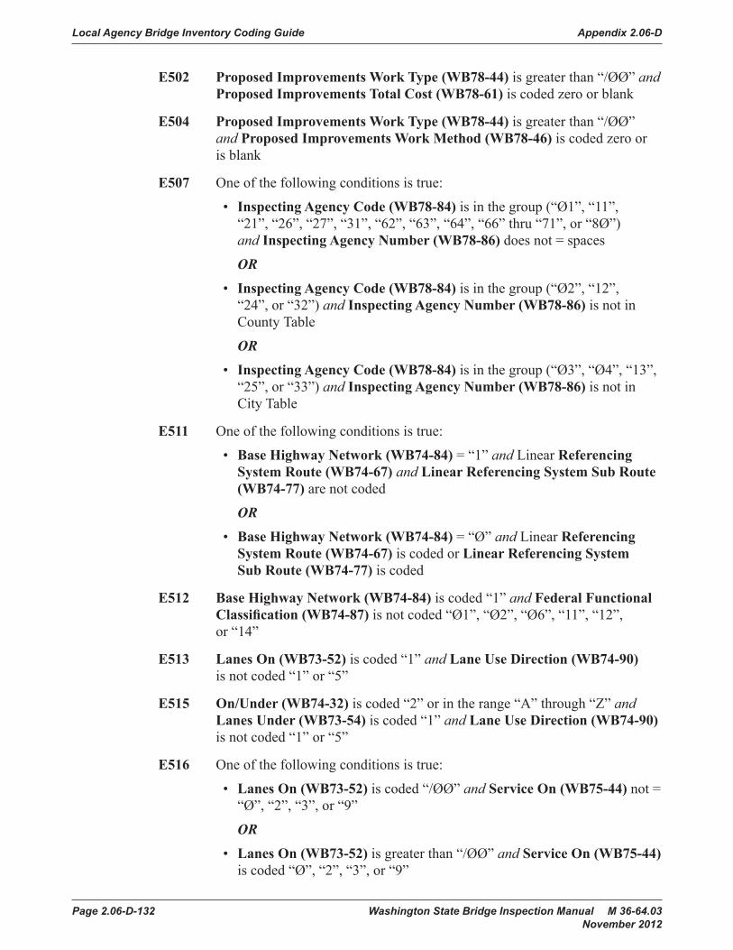
Local Agency Bridge Inventory Coding Guide Appendix 2.06-D
Page 2.06-D-132 Washington State Bridge Inspection Manual M 36-64.03 November 2012
E502 Proposed Improvements Work Type (WB78-44) is greater than “/ØØ” and Proposed Improvements Total Cost (WB78-61) is coded zero or blank
E504 Proposed Improvements Work Type (WB78-44) is greater than “/ØØ” and Proposed Improvements Work Method (WB78-46) is coded zero or is blank
E507 One of the following conditions is true:
• Inspecting Agency Code (WB78-84) is in the group (“Ø1”, “11”, “21”, “26”, “27”, “31”, “62”, “63”, “64”, “66” thru “71”, or “8Ø”) and Inspecting Agency Number (WB78-86) does not = spaces
OR
• Inspecting Agency Code (WB78-84) is in the group (“Ø2”, “12”, “24”, or “32”) and Inspecting Agency Number (WB78-86) is not in County Table
OR
• Inspecting Agency Code (WB78-84) is in the group (“Ø3”, “Ø4”, “13”, “25”, or “33”) and Inspecting Agency Number (WB78-86) is not in City Table
E511 One of the following conditions is true:
• Base Highway Network (WB74-84) = “1” and Linear Referencing System Route (WB74-67) and Linear Referencing System Sub Route (WB74-77) are not coded
OR
• Base Highway Network (WB74-84) = “Ø” and Linear Referencing System Route (WB74-67) is coded or Linear Referencing System Sub Route (WB74-77) is coded
E512 Base Highway Network (WB74-84) is coded “1” and Federal Functional Classification (WB74-87) is not coded “Ø1”, “Ø2”, “Ø6”, “11”, “12”, or “14”
E513 Lanes On (WB73-52) is coded “1” and Lane Use Direction (WB74-90) is not coded “1” or “5”
E515 On/Under (WB74-32) is coded “2” or in the range “A” through “Z” and Lanes Under (WB73-54) is coded “1” and Lane Use Direction (WB74-90) is not coded “1” or “5”
E516 One of the following conditions is true:
• Lanes On (WB73-52) is coded “/ØØ” and Service On (WB75-44) not = “Ø”, “2”, “3”, or “9”
OR
• Lanes On (WB73-52) is greater than “/ØØ” and Service On (WB75-44) is coded “Ø”, “2”, “3”, or “9”

Appendix 2.06-D Local Agency Bridge Inventory Coding Guide
Washington State Bridge Inspection Manual M 36-64.03 Page 2.06-D-133 November 2012
E603 Owner (Control Field) is coded “Ø1” and Service On (WB75-44) is coded “1” or is in the range “4” through “8” and Curb Condition (WB76-72) is blank
E605 Owner (Control Field) is coded “Ø1” and Service On (WB75-44) is coded “1” or is in the range “4” through “8” and Sidewalk Condition (WB76-73) is blank
E613 Owner (Control Field) is coded “Ø1” and Service On (WB75-44) is coded “1” or is in the range “4” through “8” and Paint Condition (WB76-74) is blank
E616 Owner (Control Field) is coded “Ø1” and Service On (WB75-44) is coded “1” or is in the range “4” through “8” and Pier Protection (WB76-83) is blank
E617 Owner (Control Field) is coded “Ø1” and Service On (WB75-44) is coded “1” or is in the range “4” through “8” and Number of Utilities (WB76-75) is blank
E618 Owner (Control Field) is coded “Ø1” and Service On (WB75-44) is coded “1” or is in the range “4” through “8” and Scaling Severity (WB76-66) is blank
E619 Owner (Control Field) is coded “Ø1” and Service On (WB75-44) is coded “1” or is in the range “4” through “8” and Scaling Percent (WB76-67) is blank
E620 Owner (Control Field) is coded “Ø1” and Service On (WB75-44) is coded “1” or is in the range “4” through “8” and Deck Rutting (WB76-69) is blank
E621 Owner (Control Field) is coded “Ø1” and Service On (WB75-44) is coded “1” or is in the range “4” through “8” and Exposed Reinforcing Steel (WB76-70) is blank
E622 Owner (Control Field) is coded “Ø1” and Service On (WB75-44) is coded “1” or is in the range “4” through “8” and Drain Condition (WB76-64) is blank
E623 Owner (Control Field) is coded “Ø1” and Service On (WB75-44) is coded “1” or is in the range “4” through “8” and Retaining Walls (WB76-82) is blank
E630 One of the following conditions is true
• Lane Use Direction (WB74-90) is coded “Ø” and Lanes On (WB73-52) is greater than zero
OR
• On/Under (WB74-32) is coded “1” and Lane Use Direction (WB74-90) is in the range “1” through “5” and Lanes On (WB73-52) is equal to zero

Local Agency Bridge Inventory Coding Guide Appendix 2.06-D
Page 2.06-D-134 Washington State Bridge Inspection Manual M 36-64.03 November 2012
L007 Future ADT (WB74-57) is greater than 2ØØ,ØØØ
L008 Future ADT Year (WB74-63) is not in the range of 17 to 23 years in the future
L009 ADT (WB74-45) is greater than 2ØØ,ØØØ
L010 Truck ADT Percent (WB74-51) is greater than 4Ø
L011 ADT Year (WB74-53) is more than 4 years old
L012 Alignment Adequacy (WB76-61) is coded “Ø” or “1”
L047 Channel Protection (WB76-77) is coded “Ø” or “1”
L085 Deck Geometry (WB76-58) is coded “Ø” or “1”
L092 Deck Overall (WB76-63) is coded “Ø” or “1”
L132 One of the following conditions is true:
• Main Span Design (WB75-33) is coded “/ØØ”
OR
• Main Span Material (WB75-32) is coded “Ø”
L158 Horizontal Clearance Reverse Direction (WB74-95) is less than 8 feet
L159 Horizontal Clearance Route Direction (WB74-91) is less than 8 feet
L163 Routine Inspection Frequency (WB76-32) is greater than 24 months
L183 Lanes On (WB73-52) is greater than 14
L184 Lanes Under (WB73-54) is greater than 2 Ø
L185 Routine Inspection Last Inspection Date (WB76-34) is more than three years old
L210 Maximum Span Length (WB73-48) is greater than 984 feet
L223 Minimum Vertical Clearance Under Bridge (WB73-74) is greater than zero and less than 7 feet
L228 Navigation Horizontal Clearance (WB73-90) is greater than 984 ft.
L229 Navigation Vertical Clearance (WB73-87) is greater than 25Ø feet.
L231 Proposed Improvements Estimate Year (WB78-79) is more than 8 years old
L232 Number of Main Spans (WB75-38) is greater than 5Ø
L233 Number of Approach Spans (WB75-41) is greater than 5Ø
L318 Operating Level (WB76-60) is coded “Ø” or “1”

Appendix 2.06-D Local Agency Bridge Inventory Coding Guide
Washington State Bridge Inspection Manual M 36-64.03 Page 2.06-D-135 November 2012
L321 Sidewalk Curb Left (WB73-64) is greater than 12 feet
L322 Sidewalk Curb Right (WB73-67) is greater than 12 feet
L339 Bridge Length (WB73-40) is greater than 3937 feet
L341 Structural Adequacy (WB76-57) is coded “Ø” or “1”
L368 Underclearance Adequacy (WB76-59) is coded “Ø” or “1”
L378 Maximum Vertical Clearance Route Direction (WB74-99) is less than 8 feet
L382 Waterway Adequacy (WB76-62) is coded “Ø” or “1”
R700 On/Under (WB74-32) is coded “1” and Year Built (WB73-32) is within the last 5 years and Deck Overall (WB76-63) is less than 5
R701 On/Under (WB74-32) is coded “1” and Year Built (WB73-32) is within the last 5 years and Superstructure Overall (WB76-71) is less than 5
R702 On/Under (WB74-32) is coded “1” and Year Built (WB73-32) is within the last 5 years and Substructure Overall (WB76-76) is less than 5
R703 On/Under (WB74-32) is coded “1” and Year Built (WB73-32) is within the last 5 years and Channel Protection (WB76-77) is less than 5
R704 On/Under (WB74-32) is coded “1” and Year Built (WB73-32) is within the last 5 years and Culvert (WB76-78) is less than 5
R705 On/Under (WB74-32) is coded “1” and Year Built (WB73-32) is within the last 5 years and Structural Adequacy (WB76-57) is less than 5
R706 On/Under (WB74-32) is coded “1” and Year Built (WB73-32) is within the last 5 years and Deck Geometry (WB76-58) is less than 5
R707 On/Under (WB74-32) is coded “1” and Year Built (WB73-32) is within the last 5 years and Underclearance Adequacy (WB76-59) is less 5
R708 On/Under (WB74-32) is coded “1” and Year Built (WB73-32) is within the last 5 years and Operating Level (WB76-60) is less than 5
R709 On/Under (WB74-32) is coded “1” and Year Built (WB73-32) is within the last 5 years and Waterway Adequacy (WB76-62) is less than 5
R710 On/Under (WB74-32) is coded “1” and Year Built (WB73-32) is within the last 5 years and Alignment Adequacy (WB76-61) is less than 5
R711 On/Under (WB74-32) is coded “1” and Year Built (WB73-32) is within the last 5 years and Inventory Rating Tons (WB75-55) is less than 2Ø tons
R712 On/Under (WB74-32) is coded “1” and Year Built (WB73-32) is within the last 5 years and Operating Rating Tons (WB75-52) is less than 2Ø tons

Local Agency Bridge Inventory Coding Guide Appendix 2.06-D
Page 2.06-D-136 Washington State Bridge Inspection Manual M 36-64.03 November 2012
R713 On/Under (WB74-32) is coded “1” and Year Rebuilt (WB73-36) is within 5 years and Deck Overall (WB76-63) is in the range “Ø” through “5”
R714 On/Under (WB74-32) is code d “1” and Year Rebuilt (WB73-36) is within 5 years and Superstructure Overall (WB76-71) is in the range “Ø” through “4”
R715 On/Under (WB74-32) is coded “1” and Year Rebuilt (WB73-36) is within 5 years and Substructure Overall (WB76-76) is in the range “Ø” through “4”
R716 On/Under (WB74-32) is coded “1” and Year Rebuilt (WB73-36) is within 5 years and Channel Protection (WB76-77) is in the range “Ø” through “4”
R717 On/Under (WB74-32) is coded “1” and Year Rebuilt (WB73-36) is within 5 years and Culvert (WB76-78) is in the range “Ø” through “4”
R718 On/Under (WB74-32) is coded “1” and Year Rebuilt (WB73-36) is within 5 years and Structural Adequacy (WB76-57) is in the range “Ø” through “4”
R719 On/Under (WB74-32) is coded “1” and Year Rebuilt (WB73-36) is within 5 years and Deck Geometry (WB76-58) is in the range “Ø” through “4”
R720 On/Under (WB74-32) is coded “1” and Year Rebuilt (WB73-36) is within 5 years and Underclearance Adequacy (WB76-59) is in the range “Ø” through “4”
R721 On/Under (WB74-32) is coded “1” and Year Rebuilt (WB73-36) is within 5 years and Operating Level (WB76-60) is in the range “Ø” through “4”
R722 On/Under (WB74-32) is coded “1” and Year Rebuilt (WB73-36) is within 5 years and Waterway Adequacy (WB76-62) is in the range “Ø” through “4”
R723 On/Under (WB74-32) is coded “1” and Year Rebuilt (WB73-36) is within 5 years and Alignment Adequacy (WB76-61) is in the range “Ø” through “4”
R727 Median (WB72-91) is coded “Ø”, or in the range “2” through “7”, or “9” and Minimum Lateral Underclearance Left (WB73-83) is coded 99.9
R729 Service On (WB75-44) is coded “1” or is in the range “4” through “8” and Approach Roadway Width (WB73-97) is less than 8 feet
R730 Service On (WB75-44) is coded “1” or is in the range “4” through “8” and Curb to Curb Width (WB73-56) is less than 9 feet
R731 Service On (WB75-44) is coded “1” or is in the range “4” through “8” and Out to Out Deck Width (WB73-60) is less than 9 feet

Appendix 2.06-D Local Agency Bridge Inventory Coding Guide
Washington State Bridge Inspection Manual M 36-64.03 Page 2.06-D-137 November 2012
R732 Service On (WB75-44) is coded “1” or is in the range “4” through “8” and Minimum Vertical Clearance Over Deck (WB73-70) is less than 7 feet
R733 Service Under (WB75-45) is coded “1”, “2”, “4”, “6”, “7” or “8” and Minimum Vertical Clearance Under Bridge (WB73-74) is zero
R736 Main Span Design (WB75-33) is in the range “/ØØ” through “18”, or “21”, or “22” and Curb to Curb Width (WB73-56) is between Ø and 9 feet or between 15Ø feet and 999 feet
R737 Main Span Design (WB75-33) is in the range “/ØØ” through “18”, or “21”, or “22” and Out to Out Deck Width (WB73-60) is between Ø and 9 feet or between 15Ø feet and 999 feet.
R738 Bridge Length (WB73-40) is between 19 feet and 23 feet and NBIS Length (WB73-46) is blank
R742 Open Closed (WB72-93) is coded “A” and Superstructure Overall (WB76-71) is in the range “Ø” through “4”
R743 Open Closed (WB72-93) is coded “A” and Substructure Overall (WB76-76) is in the range “Ø” through “4”
R744 Open Closed (WB72-93) is coded “A” and Culvert (WB76-78) is in the range “Ø” through “4”
R745 Open Closed (WB72-93) is coded “A” and Superstructure Overall (WB76-71) is greater than “4” and Substructure Overall (WB76-76) is greater than “4” and Culvert (WB76-78) is greater than “4” and Operating Rating Tons (WB75-52) is greater than 36 tons and Structural Adequacy (WB76-57) is in the range “Ø” through “3”
R746 Open Closed (WB72-93) is coded “A” and Operating Level (WB76-60) is in the range “Ø” through “4”
R747 On/Under (WB74-32) is coded “1” and Operating Rating Tons (WB75-52) is coded zero and Open Closed (WB72-93) is not coded “K” and Temporary Structure (WB72-89) is blank
R762 Routine Inspection Last Inspection Date (WB76-34) is less than the current date minus Routine Inspection Frequency (WB76-32)
R763 Curb to Curb Width (WB73-56) does not equal zero and Lanes On (WB73-52) is greater than 3 and Approach Roadway Width (WB73-97) is greater than 1.5 times Curb to Curb Width (WB73-56)
R764 Curb to Curb Width (WB73-56) does not equal zero and Lanes On (WB73-52) is less or equal to 3 and Approach Roadway Width (WB73-97) is greater than or equal to 2 times Curb to Curb Width (WB73-56)

Local Agency Bridge Inventory Coding Guide Appendix 2.06-D
Page 2.06-D-138 Washington State Bridge Inspection Manual M 36-64.03 November 2012
R765 Open Closed (WB72-93) is coded “B”, “D”, “E”, “P” or “R” and Routine Inspection Frequency (WB76-32) is not less than 24 months
R766 Open Closed (WB72-93) is not coded “D”, “E”, or “K” and any of the following fields is coded “Ø” and all others of this group are coded “2” or greater
• Deck Overall (WB76-63)
• Superstructure Overall (WB76-71)
• Substructure Overall (WB76-76)
• Culvert (WB76-78)
• Structural Adequacy (WB76-57)
• Deck Geometry (WB76-58)
• Underclearance Adequacy (WB76-59)
• Waterway Adequacy (WB76-62)
R767 Operating Level (WB76-60) is coded “5” and Superstructure Overall (WB76-71) is coded “Ø”, “1”, “2”, or “3”
R768 Operating Level (WB76-60) is coded “5” and Substructure Overall (WB76-76) is coded “Ø”, “1”, “2”, or “3”
R769 Operating Level (WB76-60) is coded “5” and Culvert (WB76-78) is coded “Ø”, “1”, “2”, or “3”
R770 Fracture Critical/UBIT Inspection Type (WB77-32) is not coded “N” and Fracture Critical/UBIT Inspection Frequency (WB77-33) is greater than “/ØØ” and Fracture Critical/UBIT Inspection Last Inspection Date (WB77-35) is older than current date minus the Fracture Critical/UBIT Inspection Frequency (WB77-33)
R771 Underwater Inspection Type (WB77-58) is not coded “N” and Underwater Inspection Frequency (WB77-59) is greater than “/ØØ” and Underwater Inspection Last Inspection Date (WB77-61) is older than current date minus the Underwater Inspection Frequency (WB77-59)
R772 Other Special Inspection Type (WB77-84) is not coded “N” and Other Special Inspection Frequency (WB77-85) is greater than “/ØØ” and Other Special Inspection Last Inspection Date (WB77-87) is older than current date minus the Other Special Inspection Frequency (WB77-85)
R773 Future ADT (WB74-57) is less than four-tenths ADT (WB74-45)
R774 Future ADT (WB74-57) is greater than 4 times ADT (WB74-45)
R775 Minimum Vertical Clearance Under Bridge (WB73-74) is coded “R” and Minimum Vertical Clearance Under Bridge (WB73-74) is less than 15´ Ø9″

Appendix 2.06-D Local Agency Bridge Inventory Coding Guide
Washington State Bridge Inspection Manual M 36-64.03 Page 2.06-D-139 November 2012
R776 Minimum Lateral Underclearance Right (WB73-79) is coded “R” and Minimum Lateral Underclearance Right (WB73-79) is less than 4¢11″
R777 Curb to Curb Width (WB73-56) is less than 16´ /ØØ″ and Lanes On (WB73-52) is greater than 1
R778 The following conditions are not met:
• Curb to Curb Width (WB73-56) is greater than 16´ /ØØ″ and
• Lanes On (WB73-52) is 2 or greater and
• Service Level (WB74-34) is not coded “7”
R779 Curb to Curb Width (WB73-56) is less than half of Out to Out Deck Width (WB73-60)
R780 One of the following conditions is true:
• National Highway System (WB74-83) is coded “1” and Federal Functional Classification (WB74-87) is not coded “Ø1”, “Ø2”, “11”, “12”, and “14”
OR
• National Highway System (WB74-83) is coded “Ø” and Federal Functional Classification (WB74-87) is not coded “Ø6”, “Ø7”, “Ø8”, “Ø9”, “16”, “17”, and “19”
R781 National Highway System (WB74-83) is coded “1” and Highway Class (WB74-33) is coded “2” or “3”
Appendix
2-A Half Bridges
Forms
WSBIS Inventory Coding FormWashington State Legislative Districts Map

Local Agency Bridge Inventory Coding Guide Appendix 2.06-D
Page 2.06-D-140 Washington State Bridge Inspection Manual M 36-64.03 November 2012

Washington State Bridge Inspection Manual M 36-64.03 Page 2.06-E-1 November 2012
Appendix 2.06-E Memorandum

Memorandum Appendix 2.06-E
Page 2.06-E-2 Washington State Bridge Inspection Manual M 36-64.03 November 2012
Washington State Bridge Inspection Manual M 36-64.03 Page 3-1 November 2012
Chapter 3 Inspections and Reports
3.01 GeneralThis chapter provides guidelines to inspect bridges, including documentation.
The guidelines presented herein are those in use by the WSDOT Bridge Preservation Office (BPO) and BPO inspection teams. Local Agencies are encouraged to follow these guidelines so as to provide a consistent basis for evaluation and reporting of inspection data. Coding for non-mandatory items may deviate according to the needs of an individual agency. Agencies are encouraged to document such deviations in a manner so as to aid in the evaluation of the associated inspection data.
The basis for bridge inspection policies and procedures are referenced throughout the chapter by the updated versions of the two following manuals: The AASHTO Manual for Bridge Evaluation (MBE) provides uniformity in the procedures and policies for determining the physical condition, maintenance needs, and load capacity of the nation’s highway bridges.
The FHWA NHI 12-049 Bridge Inspector’s Reference Manual (BIRM) is a manual on programs, procedures, and techniques for inspecting and evaluating a variety of in-service bridges. It provides guidelines regarding what preparation is necessary, how to inspect, what to look for, what equipment and tools are needed, how to document the results of the inspections, and provide appropriate follow-up to the inspection.
3.02 Inspection Types and ReportingA number of different types of inspections have been developed to address specific needs. This section will identify and describe the inspection types used by both the state and local agencies. Following is a summary description of the commonly used inspection types. Additional detailed information is provided in each referenced sub-section in the remainder of the chapter.
Routine (A) – Routine Inspections are regularly scheduled inspections consisting of observations, measurements, or both, needed to determine the physical and functional condition of the bridge, to identify any changes from “Initial” or previously recorded conditions, and to ensure that the structure continues to satisfy present service requirements. The initial inspection, commonly referred to as an inventory inspection, is the first inspection of a bridge and is typically reported to the NBI as a Routine inspection.
Fracture Critical (B) – Fracture-critical members or member components (FCMs) are steel tension members or steel tension components of members whose failure would be expected to result in a partial or full collapse of the bridge (MBE 4.11). A Fracture-Critical Inspection of steel bridges shall include the identification of all fracture-critical members (FCM) and the development of a plan for inspecting such members.
Inspections and Reports Chapter 3
Page 3-2 Washington State Bridge Inspection Manual M 36-64.03 November 2012
In-Depth (C) – An In-Depth Inspection is a close-up, hands-on inspection of one or more members above or below the water level to identify any deficiencies not readily detectable using Routine Inspection procedures.
Interim (D) – An interim inspection type in Washington State is referred to as a Special Inspection according to the MBE. This type of inspection is scheduled to monitor a known or suspected deficiency, such as foundation settlement, scour or significant member deterioration. Underwater interim inspections are similar where only a portion of the bridge or specific underwater elements are monitored at a frequency shorter than the full underwater inspection.
Damage (E) – A Damage Inspection is an unscheduled one-time inspection to assess structural damage resulting from environmental factors or human actions. The scope of inspection should be sufficient to determine the need for emergency load restrictions or closure of the bridge to traffic, and to assess the level of effort necessary to define a repair. Depending on the specific situation, a Damage inspection may be cause to initiate Interim inspections. This determination is typically made by the Team Leader or his/her supervisor.
Underwater (F) – An Underwater Inspection is the combined effort of soundings to locate the channel bottom, probing to locate deterioration of substructure and undermining, diving to visually inspect and measure bridge components, or some combination thereof.
Equipment (G) – If portions of the bridge during a Routine Inspection cannot be given close or adequate inspection from the ground (the bridge crosses a deep ravine, for example) or from the shore (the bridge crosses a wide body of water), then an Equipment Inspection may be utilized to supplement the inspection by using specialized access equipment such as a boat or an under bridge inspection truck (UBIT) on an extended frequency as determined by the agency. For bridges where such access equipment is required as a part of every Routine Inspection, the Equipment Inspection type is not used.
Special Feature (H) – Structures with Special Feature Inspections in Washington State are considered Complex bridges according to the NBIS. This inspection type is used for structures with unique design or construction such as movable bridges, floating bridges, suspension and cable-stayed bridges and ferry terminals. Also included are bridges built with special materials such as high strength steel, and bridges that were built using techniques such as segmentally constructed post-tensioned concrete boxes and bridges with pin and hanger connections.
Safety (I) – This inspection type is utilized for structures crossing over public highways which could impact public safety, but are not reported to the NBI. These include railroads, pedestrian bridges, utility bridges, highway lids and tunnels.
Short Span (J) – This inspection type is used for bridges/culverts that have an opening of 20 feet or less. This is measured along the center of the roadway between undercopings of abutments, spring lines of arches, or extreme ends of openings for multiple boxes. Short span bridges may also include multiple pipe culverts, but the

Chapter 3 Inspections and Reports
Washington State Bridge Inspection Manual M 36-64.03 Page 3-3 November 2012
clear distance between openings must be less than half of the smaller contiguous opening. Except in select defined cases, Short Spans are generally not reported to the NBI.
Two Man UBIT (K) – This inspection type is used when the UBIT, its driver and the UBIT operator are supplied by the BPO, but the responsibility for the inspection and reporting resides with the client agency. The sole purpose of this inspection type is to facilitate the scheduling of future inspections and the internal accounting and billing of current inspection work. This inspection type is not reported to the NBI.
Informational (L) – This report type is used as a means to add notes or to attach files or photos to a report between scheduled inspections. Additionally the Informational Report can be used to change the inspection frequency if necessary or to just assign a next scheduled inspection date without having to change the normal inspection frequency. An Informational Report type does not involve field work.
Unusual Circumstances – Depending on the inspection type, bridges submitted to the NBI have regular inspection intervals that must adhere to the intervals as defined within the NBIS. When a bridge is inspected late, the agency must document a justifiable cause that pushed the inspection beyond the required interval. The justifiable cause, identified as an unusual circumstance in the preamble of the NBIS regulation, should be documented within the inspection report. Some examples of unusual circumstances are as follows: severe weather, concern for inspector safety, concern for inspection quality, the need to optimize scheduling with other bridges, or other unique situations. The agency must also ensure that the next inspection is scheduled for the original inspection month during subsequent inspection cycles.
A. Routine
1. Inventory Inspection – The first routine inspection performed on any bridge is the inventory or initial inspection. An inventory inspection is also performed after rehabilitation work that changes a bridge’s dimensions or clearances, or when there is a change in bridge ownership.
The purpose of this inspection is to add the bridge to the inventory of bridges and to establish certain baseline information.
a. Gathering Inventory Data – Establishing baseline information about the bridge from the original construction plans or as-built plans can be performed in the office prior to the site inspection. Agencies shall record the required WSBIS data into BridgeWorks along with the applicable Bridge Management System (BMS) elements for the structure. Any information not known or which cannot be determined from the plans can be left blank until the site inspection.
Depending on the type of structure built, one or more of the following inspection types may also be required to be performed with the initial inspection:
• A fracture critical inspection if the bridge contains fracture critical members, see Section 3.02.B.
Inspections and Reports Chapter 3
Page 3-4 Washington State Bridge Inspection Manual M 36-64.03 November 2012
• An underwater inspection by wading or by an underwater inspection diver if one is needed to inspect underwater portions of the bridge, see Section 3.02.F.
• An equipment inspection utilizing specialized equipment if during the routine inspection, certain bridge elements cannot be reached for sufficient examination, see Section 3.02.G.
• A special features inspection if the bridge contains unique design or construction elements, see Section 3.02.H.
Conclusions and findings from these items should be incorporated into the Bridge Inspection Report (BIR) to support the applicable codes and ratings.
Team leaders should coordinate the planning and timing of the inspection with the appropriate project or construction offices prior to visiting the site.
b. Site Inspection – After the bridge has been built, and preferably before it is placed into service, the team leader must visit the bridge site to verify the inventory information that has been coded and to establish any information that was not known. At the bridge site, the team leader can review the information to confirm the actual bridge dimensions and clearance measurements and to verify the condition of all bridge elements.
Changes or additions to the WSBIS data, the BIR form, or BMS elements, must be noted on the inspection form and entered into BridgeWorks.
c. Check Coding – The BIR form should note any inconsistencies found between the planned and the as-built bridge and should provide an explanation of any coding changes made. For example, if surface cracks have been found in a newly-poured bridge deck but these cracks do not warrant lowering the condition coding for the deck, the team leader should note the location and extent of the cracking so that it can be looked for and further evaluated during future inspections.
As part of the inventory inspection, two photographs of the bridge should be taken: an elevation and a deck photograph. The elevation photograph should be taken (looking north or east) to show a view from one side of the bridge. The deck photograph should be taken (ahead on station) to show a view of the bridge looking onto the bridge deck.
See Section 3.02.A.2 for instructions on completing the remainder of the BIR form.
d. Updating the Bridge File – The WSBIS Inventory Record, the BIR, and the two photographs provide a record of the inventory inspection. In addition to being stored within BridgeWorks, these items must be placed in the bridge file created for the given bridge. Each time the bridge is revisited, additional inspection reports, any new photos, and any updates to the WSBIS and to the BIR form are added to the file so that the bridge records remain current. See Section 2.02 for further details.

Chapter 3 Inspections and Reports
Washington State Bridge Inspection Manual M 36-64.03 Page 3-5 November 2012
2. Routine Inspections – Generally, a regular inspection of the entire bridge is to be performed on regular intervals not to exceed 24 months throughout the life of the bridge. However, the NBIS does allow for extended inspection frequencies of up to 48 months provided the bridge meets specific criteria submitted by the State and approved in writing by the FHWA. Inspection intervals less than 24 months for specific reasons can be developed and documented by the inspecting agency if necessary.
a. Inspecting Bridge Components – The BIRM describes the general inspection procedures to be followed for inspecting any concrete, steel, or timber bridge, and the specific procedures to follow for inspecting a given bridge element (i.e., the bridge abutments). These steps can be used by the team leader as a checklist to help accomplish the inspection and to help spot particular types of problems a given bridge or bridge element will be prone to. Following these procedures will help ensure that a thorough and comprehensive inspection is achieved.
However, specific problems not covered in these general procedures may be encountered. If that is the case, the team leader may contact their respective WSDOT Bridge Program Support personnel.
b. Inspecting for Scour – The routine inspection of any bridge over water should include an assessment of existing scour conditions, the affect of scour on the bridge, effectiveness of countermeasures, and recommendations for repair, if appropriate. The following manuals as well as the BIRM discusses inspection procedures of bridges over water:
• HEC 20 Stream Stability at Highway Structures Fourth Edition
• HEC 23 Bridge Scour and Stream Instability Countermeasures; Experience, Selection, and Design Guidance Third Edition
The field inspection is used in conjunction with the scour analysis, see Section 5.03, to identify and verify the potential of harmful effects of scour to the bridge.
The Scour Field Evaluation form was developed to supplement the BIR for water crossings by measuring the streambed cross-section (soundings) at a bridge and to document observations related to scour. It is to be completed by the inspection team leader during the on-site inspection. A copy of this form is shown in Section 3.05.
Soundings of streambed elevations should be taken during the initial routine inspection and during subsequent inspections as required. The form should note the location and depth of the streambed at each point where a sounding was taken. This information should then be plotted over time to show any changes to the channel bottom.
The form should also note the specific location and extent of any deterioration, damage, or undermining in:
• The stream channel and stream banks.

Inspections and Reports Chapter 3
Page 3-6 Washington State Bridge Inspection Manual M 36-64.03 November 2012
• The substructure elements (i.e., intermediate piers, pier walls, web walls, columns, or shafts).
• The foundation (i.e., footings and seals).
• Channel protection devices (i.e., dams and levees).
• Scour countermeasures (i.e., riprap or shielding).
Finally, the form should recommend any repairs, replacement, or maintenance required. Such comments need to be included in the BIR.
c. Bridge Inspection Report – A bridge inspection report must be prepared at the completion of each routine inspection to record the inspection findings, provide a narrative description of conditions at the bridge site, and note any changes in the WSBIS coding information. The team leader shall record and submit the findings of the routine inspection into BridgeWorks.
The Bridge Inspection Report form will have the following preprinted information that will identify the bridge:
• Bridge Number – The bridge number given by the owner agency that is associated with the particular structure.
• Bridge Name – The bridge name given by the owner agency that is associated with the particular structure.
• Structure ID – The unique federal structure identification number associated with the particular structure in the NBI assigned by WSDOT.
• Route – The number of the inventory route carried on or under the bridge.
• Milepost – The bridge’s milepost location on the inventory route.
• Intersecting – The feature or features which intersect with the bridge.
• Location – The physical location of the bridge.
• Structure Type – The structure type (for local agency bridges, this field may be blank).
d. Completing the Bridge Inspection Report
(1) At the conclusion of the routine inspection, confirm the condition and adequacy coding for the various bridge elements and make any changes as necessary. Review the Adequacy Appraisal codes, NBI condition codes, BMS elements and their respective condition states, and complete the narrative describing the existing conditions.
(2) Enter onto the inspection report: team leader initials, team leader identification number, assistant inspector initials, date of inspection, and total number of crew hours at the bridge site. The team leader and assistant inspector are required to sign the approved and released copy of the BIR that is placed in the bridge file.

Chapter 3 Inspections and Reports
Washington State Bridge Inspection Manual M 36-64.03 Page 3-7 November 2012
(3) Prepare a list of any bridge elements in need of repair and recommend the type of repair that should be done. A photo of repair areas should be taken with each type of recommended repair. See Section 6.03 for additional repair instructions and procedures.
(4) If it is determined that a critical bridge deficiency has been identified resulting in an emergency load restriction, lane closure, bridge closure or a failed bridge, a Damage inspection and/or a subsequent In-Depth inspection may have to be performed, see Section 3.02.E for Damage inspections, and Section 3.02.C for In-Depth inspections.
e. Updating the WSBIS Inventory Record – Any changes that need to be made to the WSBIS Inventory Record shall be entered into BridgeWorks.
After the data is processed and updated, a new WSBIS Inventory Record is generated for each bridge that has changes. On all Routine inspections, all changes/updates to NBI data shall be released into the inventory within 90 days of the date of inspection.
The updated WSBIS Inventory Record and other applicable reports shall be filed in their respective bridge file.
3. Routine Inspections with Extended Intervals – Routine inspections with extended inspection intervals are structures with inspection frequencies greater than twenty-four months not exceeding forty-eight months, and only with written FHWA approval.
The criteria approved by FHWA shall be re-evaluated after every inspection. Refer to the WSDOT letter sent to FHWA, dated July 28, 1998, see Appendix 3.06-C for further details. Team leaders for the State shall place the following note in the zero (0) note of the BIR within BridgeWorks for existing extended interval bridges and candidate bridges:
“Continue to validate the status of this bridge each inspection as a 48-month inspection candidate. Verify condition ratings, load ratings, vertical clearances, ADT, scour codes when applicable, and that no major maintenance has been completed in the last two years.”
The procedures and guidelines used for routine inspections at 24 month intervals shall be used for these structures as well.
B. Fracture Critical
The National Bridge Inspection Standards (NBIS) require that a fracture critical inspection be performed on regular intervals not to exceed 24 months on bridge members identified as fracture critical. According to the MBE, a fracture critical member is a steel tension member in a bridge whose failure could result in the partial or total collapse of the bridge.

Inspections and Reports Chapter 3
Page 3-8 Washington State Bridge Inspection Manual M 36-64.03 November 2012
This section provides information to assist the team leader in identifying fracture critical bridge members, preparing written procedures, planning and performing effective fracture critical inspections and completing the required inspection report. The information presented here is meant as a summary of the main points of the fracture critical inspection. A complete description of fracture critical members and fracture critical inspection procedures are provided in the BIRM.
1. General – Each agency shall identify the bridges within its jurisdiction which contain fracture critical members. The agency can then identify, through documentation, the particular fracture critical members within each bridge. For the member to be considered fracture critical, two conditions must exist.
a. The member must be in tension. The area of the bridge where the member is located is subject to tensioning (expanding) forces.
b. There is no redundancy in the member or the bridge. There must be no other structural elements able to carry the load of the member if the given member fails.
There are three types of redundancy—load path, structural, and internal. Only load path redundancy is evaluated to determine whether a member is fracture critical. Load path redundancy is the number of supporting elements, usually parallel, such as girders or trusses. AASHTO neglects structural and internal redundancies in determining whether a member is fracture critical. For a bridge to be redundant, it must have more than two load paths.
2. Bridge Types – The following is a list of the types of bridges in which fracture critical members will be found. Figures are also shown which illustrate these bridge types and note the location of the fracture critical areas.
a. Two-Beam or Two-Girder Systems (Figure 3.02.B-1)
(1) Simple Spans – Each beam or girder should be considered fracture critical as failure of either one could cause the bridge to collapse (Example A).
(2) Continuous Spans – In general, at the midpoint of the span, the bottom of the girder should be considered fracture critical and over the pier, the top of the girder should be considered fracture critical. A structural engineer may need to assess the bridge to determine the actual redundancy and presence of fracture critical elements (Example B).
(3) Cantilever-Suspended Span – In addition to the bottom of the girder at mid-span and the top of the girder over the pier, the top flange and adjacent portion of the web in the area of the cantilevered support should be considered fracture critical (Example C).

Chapter 3 Inspections and Reports
Washington State Bridge Inspection Manual M 36-64.03 Page 3-9 November 2012Washington State Bridge Inspection Manual Page 3-17
January 2002
Inspections and Reports
Two-beam or Two-girder SystemFigure 3.05.C-1
In-Span Hinge
Figure 3.02.B-1

Inspections and Reports Chapter 3
Page 3-10 Washington State Bridge Inspection Manual M 36-64.03 November 2012
b. Truss Systems (Figure 3.02.B-2) – Most truss bridges employ only two trusses and are thus considered fracture critical. All truss members in tension should be regarded as fracture critical. The exception is, when a detailed analysis by an experienced structural engineer, verifies loss of a member would not result in collapse of the bridge or major component.
The following elements within any truss bridge should also warrant special attention:
(1) Pin-Connections – Any pin connections on a truss bridge should be considered fracture critical.
(2) Category D and E Welds – On a truss bridge, any tension member containing a Category D or E weld.
Inspections and Reports
Page 3-18 Washington State Bridge Inspection ManualJanuary 2002
b. Truss Systems (Figure 3.05.C-2)
Most truss bridges employ only two trusses and are thus consideredfracture critical. For inspectors, all truss members in tension should beregarded as fracture critical. The exception is, when a detailed analysisby an experienced structural engineer, varifies loss of a member wouldnot result in collapse of the bridge or major component.
The following elements within any truss bridge should also warrantspecial attention:
(1) Pin-connections: Any pin connections on a truss bridge should beconsidered fracture critical.
(2) Category D and E Welds: On a truss bridge, any tension membercontaining a Category D or E weld. (See Inspecting Steel Bridgesfor Fatigue Damage published by Pennsylvania DOT.)
c. Tied Arches (Figure 3.05.C-3)
The tie girder which keeps the supports from spreading apart is in tensionand should be considered fracture critical.
Tied Arch BridgeFigure 3.05.C-3
Truss SystemFigure 3.05.C-2
Figure 3.02.B-2
c. Tied Arches (Figure 3.02.B-3) – The tie girder which keeps the supports from spreading apart is in tension and should be considered fracture critical.
Inspections and Reports
Page 3-18 Washington State Bridge Inspection ManualJanuary 2002
b. Truss Systems (Figure 3.05.C-2)
Most truss bridges employ only two trusses and are thus consideredfracture critical. For inspectors, all truss members in tension should beregarded as fracture critical. The exception is, when a detailed analysisby an experienced structural engineer, varifies loss of a member wouldnot result in collapse of the bridge or major component.
The following elements within any truss bridge should also warrantspecial attention:
(1) Pin-connections: Any pin connections on a truss bridge should beconsidered fracture critical.
(2) Category D and E Welds: On a truss bridge, any tension membercontaining a Category D or E weld. (See Inspecting Steel Bridgesfor Fatigue Damage published by Pennsylvania DOT.)
c. Tied Arches (Figure 3.05.C-3)
The tie girder which keeps the supports from spreading apart is in tensionand should be considered fracture critical.
Tied Arch BridgeFigure 3.05.C-3
Truss SystemFigure 3.05.C-2
Figure 3.02.B-3

Chapter 3 Inspections and Reports
Washington State Bridge Inspection Manual M 36-64.03 Page 3-11 November 2012
d. Suspension Spans (Figure 3.02.B-4)
(1) Cables – If the main suspension member is a cable, the cable should be considered fracture critical (Example A).
(2) Cable Stayed Bridge – The bridge is of such complexity that it should be reviewed by a structural engineer to determine the criticality of the various stays to fracture (Example B).
Washington State Bridge Inspection Manual Page 3-19January 2002
Inspections and Reports
d. Suspension Spans (Figure 3.05.C-4)
(1) Cables: If the main suspension member is a cable, the cable should beconsidered fracture critical. (Example A)
(2) Cable Stayed Bridge: The bridge is of such complexity that it shouldbe reviewed by a structural engineer to determine the criticality of thevarious ties to fracture. (Example B)
Suspension SpansFigure 3.05.C-4
Example A: Cable Suspension Bridge
Example B: Cable Stayed Bridge
Figure 3.02.B-4

Inspections and Reports Chapter 3
Page 3-12 Washington State Bridge Inspection Manual M 36-64.03 November 2012
e. Other Fracture Critical Bridge Details
(1) Steel Cross Beams and Caps – Tension zones of the I section or box beam should be considered fracture critical (Figure 3.02.B-5).
Inspections and Reports
Page 3-20 Washington State Bridge Inspection ManualJanuary 2002
e. Other Fracture Critical Bridge Details
(1) Steel Cross Beams and Caps: In mid-span, the lower portion of theI-section or box beam is in tension and should be considered fracturecritical. (Figure 3.05.C-5)
Steel Cross BeamFigure 3.05.C-5
(2) Pin and Hanger Supports: The pin and hanger connection used tosupport a suspended span from a cantilever span should be consideredfracture critical if the member is nonredundant. The pin connection andhanger support in a two-girder or three-girder system is fracture criticalas the bridge has no built in redundancy. The same connections in amulti-beam system are not fracture critical as the bridge has a highdegree of redundancy. However, due to the poor performance of pinsin multi-beam suspended spans, the pin connections in such bridgesshould be inspected as if it were fracture critical. (Figure 3.05.C-6)
Pin and HangerFigure 3.05.C-6
Figure 3.02.B-5
(2) Pin and Hanger Supports – The pin and hanger connection used to support a suspended span from a cantilever span should be considered fracture critical if the member is non-redundant. The pin connection and hanger support in a two-girder or three-girder system is fracture critical as the bridge has no built in redundancy. The same connections in a multi-beam system (more than 3 beams) are not fracture critical as the bridge has a high degree of redundancy. Pin connections in such bridges should be inspected with the same techniques and methods as fracture critical pins (Figure 3.02.B-6).
Inspections and Reports
Page 3-20 Washington State Bridge Inspection ManualJanuary 2002
e. Other Fracture Critical Bridge Details
(1) Steel Cross Beams and Caps: In mid-span, the lower portion of theI-section or box beam is in tension and should be considered fracturecritical. (Figure 3.05.C-5)
Steel Cross BeamFigure 3.05.C-5
(2) Pin and Hanger Supports: The pin and hanger connection used tosupport a suspended span from a cantilever span should be consideredfracture critical if the member is nonredundant. The pin connection andhanger support in a two-girder or three-girder system is fracture criticalas the bridge has no built in redundancy. The same connections in amulti-beam system are not fracture critical as the bridge has a highdegree of redundancy. However, due to the poor performance of pinsin multi-beam suspended spans, the pin connections in such bridgesshould be inspected as if it were fracture critical. (Figure 3.05.C-6)
Pin and HangerFigure 3.05.C-6
Figure 3.02.B-6

Chapter 3 Inspections and Reports
Washington State Bridge Inspection Manual M 36-64.03 Page 3-13 November 2012
3. Prepare Written Procedures – Once the fracture critical members within a bridge have been identified, the agency must prepare a detailed plan as to how it will accomplish the fracture critical inspection. This written procedure may be developed by others being hired to perform the fracture critical inspection. However, if this is done, a qualified designee from the owner agency should carefully review the written plan to ensure that a sufficient analysis of the member will be made and that the task will be accomplished in a reasonable manner. These written inspection procedures are to be kept in each bridge file.
Fracture critical inspections can prove costly; therefore, in the development of the inspection plan, particular attention should be given to each of the following:
a. Scheduling – Generally, it will be best to schedule a fracture critical inspection during cold weather (as cracks will be more visible), at low water (if the fracture critical member is underwater at high water), during daylight hours, and when traffic on the bridge will be lightest (as some form of traffic control may be necessary).
b. Equipment – The team leader will require close access to each fracture critical member; thus, some type of equipment may be needed to provide sufficient access. Ladders, scaffolding, aerial work platforms, or UBITs may be deemed appropriate for a given situation. The choice of equipment will depend on the cost of rental, the time needed to perform the inspection using that equipment, and equipment availability. If a UBIT is used, it should be determined, before its use, whether it could overload the bridge, operate on the bridge grade, has sufficient reach, and if it might damage the deck. Use of a UBIT may also create a need for traffic control.
c. Workforce – In order to keep the amount of time spent at the bridge site to a minimum, consideration should be given to the level of manpower needed. Once the number of individuals needed is determined, the duties to be performed by each individual should be clearly defined.
d. Tools – The standard tools common to any routine inspection should be on hand for the fracture critical inspection. In particular, a wire brush, a magnifying glass, and a light source able to provide 50 to 100 lumens should be considered. In addition, specialized tools for carrying out nondestructive testing may also be warranted (i.e., a dye penetrant kit or ultrasonic testing device).
e. Inspection Procedures – The fracture critical member inspection plan should identify the inspection frequency and method(s) to be used. These should be developed depending on the criticality of the feature based on experience with other similar details or structures, calculated remaining fatigue life, current indications, material properties, consequences and likelihood of rapid failure, etc.
If several types of inspection are employed, identify when, where and how they are to be used. For example, a pinned truss bridge may require each of the pins to be examined visually during each inspection, supplemented by

Inspections and Reports Chapter 3
Page 3-14 Washington State Bridge Inspection Manual M 36-64.03 November 2012
ultrasonic testing of 1/3 of the pins during each inspection. Therefore, all of the pins would be inspected ultrasonically in a 72-month period, if the inspection frequency was 24 months.
4. Perform the Fracture Critical Inspection – The purpose of the fracture critical inspection is to assess the structural condition of each bridge member identified as fracture critical. When inspecting these members, it is always best to err on the side of conservatism. The consequences of dismissing or failing to note a blemish on a fracture critical member are too great. Therefore, the inspection should be conducted carefully and thoroughly. Such close inspection of single members can be tedious; however, the team leader should work in a manner that insures the same degree of care and attention to the last area inspected as the first. The previous pages described the general areas within a bridge where fracture critical members will be located. The following pages describe the particular features to note.
First, the team leader must gain access to the fracture critical area. The team leader should be no further than 24 inches from the surface being inspected and should work with a light source of at least 50 to 100 lumens. The best viewing angle is at approximately 120°. The team leader will want to look for deteriorated surfaces or surface cracks. The BIRM discusses inspection procedures and the types of problems that may be found.
The following areas or members should be checked:
• Areas vulnerable to corrosion (under deck joints, on surfaces where water collects, in places where dissimilar materials meet).
• Areas where there is a change in the bridge cross section, where stress is concentrated, or which show out-of-plane bending.
• Web stiffeners (especially at the ends).
• Coped sections and/or re-entrant corners.
• Eyebars.
• Shear connectors.
• Pin and hanger assemblies.
• Punched holes.
• Rivet and bolt heads.
• Tack welds and field welds (especially at weld ends or returns).
If any cracks, blemishes, or other irregularities are found, the team leader will need to evaluate these further, which may include the use of a magnifying glass. A dye penetrant kit can be used to establish the limits of a crack. Use of magnetic or ultrasonic testing devices may be required to detect internal problems not apparent to the eye. The agency will need to determine which devices will be the most cost effective and reliable for the given situation.

Chapter 3 Inspections and Reports
Washington State Bridge Inspection Manual M 36-64.03 Page 3-15 November 2012
Finally, the team leader will need to record the location and size of any cracks found. Mark and date the crack ends in permanent marker for follow up on the structure. In most cases, it will be helpful to take a photograph of such cracks to provide visual documentation. This information and the photographs are to be included in the Visual Fracture Critical Inspection Report.
5. Prepare the Visual Fracture Critical Inspection Report – At the conclusion of the fracture critical inspection, a Visual Fracture Critical Inspection Report should be prepared to provide detailed verification of the inspection findings. The report should provide qualitative and quantitative information concerning the fracture critical member. This information is important for a number of reasons: it can offer insight about the condition of the member, it can provide a history of the bridge, and it can be used to substantiate the thoroughness of the inspection effort in the event of litigation arising from a bridge failure. See Section 3.05 for a copy of the Visual Fracture Critical Inspection Report form.
The inspection report should:
• Identify what parts of the bridge were inspected and the location of each fracture critical bridge member. (This can be shown on a photograph or sketch of the bridge.)
• Describe the procedures followed to inspect the fracture critical member.
• Describe the condition of the fracture critical member.
• Provide the following details about any defects found:
– What the defect is.
– Where the defect is located (a sketch may be used to illustrate its location relative to the ends of the member, and its position in the cross section of the member).
– Summarize the inspection findings (addressing how individual defects affect the member’s overall condition).
– Make any appropriate recommendations (i.e., repair the fracture critical member, recalculate load ratings, close the bridge).
6. Updating the WSBIS Inventory Record – Any changes that need to be made to the WSBIS Inventory Record shall be entered into BridgeWorks.
On all Fracture Critical inspections, all changes/updates to NBI data shall be released into the inventory within 90 days of the date of inspection.
7. Updating the Bridge File – Place the signed and completed Visual Fracture Critical Inspection Report within the bridge file. This report can be referred to if necessary to help determine the appropriate inspection frequency for the bridge, evaluate the degree to which bridge conditions have changed from one inspection to the next, and determine what maintenance or repair may be required on the bridge.

Inspections and Reports Chapter 3
Page 3-16 Washington State Bridge Inspection Manual M 36-64.03 November 2012
C. In-Depth
Any time a bridge element or portion of the bridge requires further evaluation, analysis, or investigation to accurately assess its condition, complete an in-depth inspection. This inspection may involve testing, monitoring, or conducting specific analyses of given bridge elements.
1. Identify Need – Any time the structural condition of an element cannot be determined in the course of a routine inspection, an in-depth inspection may be required. The in-depth inspection is performed to obtain more sophisticated data, perform special testing, and/or bring in other experts to assess a particular problem.
The need for an in-depth inspection generally arises as a result of a routine inspection; however, such a need may also be the result of a damage, flood, or interim inspection. Whenever such a need is discovered, an in-depth inspection should be performed.
In-depth inspections do not have inspection intervals and are treated as one-time only inspections. If the inspecting agency feels that subsequent inspections are needed on regular intervals, interim inspections should be utilized instead.
2. Performing the Inspection – The in-depth inspection should include as detailed analysis as necessary to determine the condition of the given bridge element. There can be no standard set of procedures to follow or observations to be made. Many factors will influence the depth and extent of analysis required. To facilitate accomplishment of the inspection, the team leader should make sure that any traffic control measures or necessary special equipment will be available.
3. Reporting – There is no standard form to be completed for reporting in-depth inspection findings. When the inspection is concluded, the team leader should prepare a BIR along with any additional documentation to note:
• The location of each bridge element inspected.
• The procedures used to analyze and assess the particular bridge element.
• The names, titles, and observations made by any specialists who were consulted.
• The results of any testing performed.
• Any recommendations for maintenance or repair.
4. Updating the WSBIS Inventory Record – Any changes that need to be made in the WSBIS inventory record shall be entered into BridgeWorks.
On all In-Depth inspections, all changes/updates to NBI data shall be released into the inventory within 90 days of the date of inspection.
5. Updating the Bridge File – A copy of the report and an updated copy of the WSBIS Inventory Record (if applicable) shall be placed in the bridge file at the completion of the In-Depth Inspection and must be cross referenced to the current Bridge Inspection Report.

Chapter 3 Inspections and Reports
Washington State Bridge Inspection Manual M 36-64.03 Page 3-17 November 2012
D. Interim
Special inspections as defined in the MBE are called Interim inspections in the state of Washington. This inspection type is used any time a particular known or suspected deficiency needs to be monitored between routine inspections.
1. Identifying Need – The Interim inspection is performed to monitor a particular known or suspected deficiency and is carried out between regularly scheduled routine inspections. For example, if noticeable settling has occurred in the foundation, or if a particular bridge member shows signs of rapid deterioration. The team leader should observe and monitor this condition to determine the effect on the bridge or the danger posed to the bridge.
The inspection interval may vary depending on the type of deficiency being inspected. Interim inspections may occur between regularly scheduled Routine inspections on 24 month intervals, typically on the off year of the Routine inspection. Underwater Interim inspections typically may also occur between regularly scheduled Underwater inspections, but on 30 month intervals. There are cases where interim inspections may occur several times during a calendar year on three or six month intervals. The inspecting agency along with the team leader will determine the appropriate inspection interval.
2. Performing Inspection – The team leader is free to schedule an interim inspection at his or her discretion as the need arises. This type of inspection can be accomplished by any suitable person who has some familiarity with the bridge. That is, the team leader need not be present during the inspection. However, if someone other than the team leader will perform the inspection, this individual should be carefully instructed as to what to look for, what measurements to take, what results might be expected, and/or how the problem can affect the structural integrity of the bridge.
3. Reporting – A BIR documenting the inspection findings should be prepared by the individual who performed the inspection. Any of the following information may be appropriate to include:
• The date of interim inspection.
• The team leader’s name.
• The applicable inspection interval.
• The location of the element or elements inspected.
• Any measurements taken.
• The procedures utilized to analyze and assess the given bridge element(s).
• The results of any testing performed.
• Any recommendations for maintenance or repair.

Inspections and Reports Chapter 3
Page 3-18 Washington State Bridge Inspection Manual M 36-64.03 November 2012
4. Updating the WSBIS Inventory Record – Any changes that need to be made to the WSBIS Inventory Record shall be entered into BridgeWorks. The routine bridge inspection date should not be changed due to an interim inspection. On all interim inspections, all changes/updates to NBI data shall be released into the inventory within 90 days of the date of inspection
5. Updating the Bridge File – A copy of the report and an updated copy of the WSBIS Inventory Record (if applicable) must be placed in the bridge file at the completion of the interim inspection and must be cross referenced to the current Bridge Inspection Report.
E. Damage
Damage inspections are categorized by type based on the damage received or how it was found or is being reported. Team leaders should create a Damage inspection report in BridgeWorks and choose one of the following categories:
• Collision – Damage typically caused by over height loads.
• Flooding – Damage as a result of scour to the channel beneath the structure.
• Earthquake – Damage caused by seismic events.
• Other – Damage/defects found during normal inspection that result in loss of capacity, or for other undefined types of damage.
• Reported by Others – Minor damage typically caused by over height loads but reported by maintenance forces. This damage type is used primarily by the state to track deterioration over time.
Damage inspections do not have inspection intervals but subsequent In-Depth and/or Interim inspections may be scheduled as a result of the damage to monitor the structure over time.
If called upon to perform a Damage Inspection, team leaders should get familiarized with the type of bridge and the location of the damage. Office review of as-built plans and photos should take place prior to inspecting the damaged structure.
1. Assess Damage – When damage occurs as a result of collision, earthquake, or other forces, a thorough examination of the damaged areas should be made, along with an assessment of any residual damage to other bridge components. The amount of time and effort required to make this assessment will depend upon the extent and seriousness of the damage.
If significant damage has occurred, the team leader will need to:
• Identify any fractured members.
• Determine any loss of foundation support.
• Compute the amount of any section loss.
• Measure the amount any member is out of alignment.
• Inform the bridge owner that an updated load rating may be necessary.

Chapter 3 Inspections and Reports
Washington State Bridge Inspection Manual M 36-64.03 Page 3-19 November 2012
Any time flooding has occurred on the waterway the bridge crosses, an inspection should be conducted both during and immediately after the flooding to assess what effects the increased water flow is having, or had, on the bridge. The following explains these procedures:
(a) During Event Inspection – An inspection during the flood can provide information about the structure’s safety and condition under adverse conditions. Observations made during the flood may help the team leader recommend appropriate measures to protect the bridge from failure or damage due to any future flooding.
To the extent possible during the flood, the team leader should look for the suggestion or the presence of any of the following:
• Streambed scour around underwater bridge elements.
• Bank erosion.
• Lateral migrations in the channel.
• Sediment transport or accumulation.
• Debris transport or accumulation (especially around piers).
(b) Follow-up Inspection – The bridge should be revisited immediately after the flood to assess any damage to the bridge and to provide information about the actual impact of the flood. The team leader should assess the impact of any of the following:
• Streambed scour around underwater bridge elements.
• Bank erosion.
• Lateral migrations in the channel.
• Sediment transport or accumulation.
• Debris transport or accumulation (especially around piers).
2. Reporting – After a Damage Inspection report has been created within BridgeWorks, descriptions and comments shall be added under the appropriate BMS elements describing the damage. In addition to the inspection report, a Bridge Damage Report is also required for all Damage inspections performed by the state, See Section 6.02 for further instructions.
For collision and over height damage, add the BMS Element #362, Impact Damage flag, if required. Add the damage photos and revise the BMS condition state codes if necessary. The following information should also be noted:
• The location, extent, and type of any damage found.
• The amount of any section loss.
• The degree to which any members are out of alignment.
• The need for new load ratings, if applicable.
• Any recommendations for repair or maintenance.
Inspections and Reports Chapter 3
Page 3-20 Washington State Bridge Inspection Manual M 36-64.03 November 2012
For prestressed concrete or steel bridges fill out the Prestressed Concrete and Steel Damage Report form or equivalent to supplement the BIR and the Bridge Damage Report form, see Section 3.05.
If the bridge is damaged as a result of the flood or if conditions have changed at the bridge site, a Bridge Damage Report and a new Scour Field Evaluation form must be completed. If the bridge is a scour critical structure, the instructions within the Plan of Action (POA) should be followed, see Section 5.03.B.
The report should provide the following information:
• Flood stage at which the bridge was visited.
• Approximate streamflow volume and velocity at the time of the visit.
• Location and extent of any damage to the bridge.
• Current condition of any bridge elements affected by the flood.
• Any recommendations for scour countermeasures, bank protection, channel protection, etc., which may protect the bridge from damage during future flooding or reduce the potential for future flooding.
3. Critical Damage-Bridge Repair Report (CDBRR) – If the bridge has been damaged to the extent that has resulted in an emergency load restriction, lane closure, or a bridge closure, a CDBRR, which is part of the Bridge Damage Report, shall be used, see Section 6.02 for further instructions. A copy of this report shall be entered into BridgeWorks and another copy shall be sent to FHWA for initial report and any subsequent updates.
4. Updating the WSBIS Inventory Record – If any changes to the WSBIS Inventory Record (the inventory or load ratings, for example) are needed, they must be entered into BridgeWorks. On all Damage inspections, all changes/updates to NBI data shall be released into the inventory within 90 days of the date of inspection.
5. Updating the Bridge File – A copy of the BIR and an updated copy of the WSBIS Inventory Record (if applicable), a copy of the Bridge Damage Report and all other applicable forms and drawings shall be placed in the bridge file at the completion of the Damage Inspection.
F. Underwater
Bridges over water have special inspection requirements. If the bridge has members in water too deep to permit a visual or tactile (hands-on and/or wading) inspection from the surface at low water or during seasonal low stream flows, an underwater bridge inspection diver must conduct an underwater inspection. An evaluation of the bridge’s susceptibility to scour also needs to be conducted, see Section 5.03. Many bridge failures are due to underwater or scour problems; therefore, the importance of these types of inspection cannot be overemphasized. There may be environmental restrictions that need to be taken into consideration prior to conducting an underwater inspection.

Chapter 3 Inspections and Reports
Washington State Bridge Inspection Manual M 36-64.03 Page 3-21 November 2012
An underwater inspection of submerged bridge elements is required on an interval not to exceed 60 months. The purpose of the underwater inspection is to examine the underwater elements to the extent necessary to determine their structural condition and adequacy. At a minimum, an underwater bridge inspection diver must swim by and examine all underwater portions of the bridge. If the underwater elements are covered with marine growth, portions of the structure need to be cleaned in order to positively ascertain the condition of the element. For concrete piers, this consists of cleaning 1 square foot patches near the surface, mid height, and bottom of all piers. For multiple pile bents, a one foot band must be cleaned near the surface, mid-height and bottom of one pile per bent, but no less than 10 percent of the piles. The underwater bridge inspection diver must also perform a visual or tactile inspection of the entire bridge footing at ground line to identify if any undermining of the footing exists, as well as probing to determine if scour holes are being filled in. If significant problems are encountered during the course of the inspection, a more detailed inspection of the bridge may be needed.
Existing scour conditions must be evaluated during an underwater inspection. The team leader must assess condition and depth of the streambed, determine the susceptibility of the streambed to scour, and determine what countermeasures can be taken to safeguard the bridge. The primary requirement of the scour inspection is to establish a cross-section of the streambed. This is accomplished by sounding and can be carried out with either a fathometer (also known as a “fish finder”) or a lead line. See the BIRM and the MBE for guidance on performing underwater inspections.
1. Prepare Written Procedures – Written inspection procedures need to be developed for each bridge requiring an underwater inspection. The inspection plan should detail as a minimum:
• Type and frequency of required inspection.
• Location of members to be inspected.
• Type(s) of foundation.
• Bottom of foundation elevation or pile tip elevation.
• Identification of scour critical substructure units.
• Special equipment requirements.
• Follow-up actions taken on findings of last inspection.
2. Document the Underwater Inspection – Prepare a Daily Site Dive Log for each dive and prepare an Underwater Inspection Report when inspection of the entire underwater portion of the bridge is concluded.
a. Daily Site Dive Log – The Daily Site Dive Log must be completed by the inspection team leader (in concert with the diver). Section 3.05, provides a sample of the Daily Site Dive Log form. The form should summarize what equipment was used in the dive, what procedures were employed, what problems were encountered (such as strong currents or underwater obstructions or accumulations of debris), and should provide any information which may

Inspections and Reports Chapter 3
Page 3-22 Washington State Bridge Inspection Manual M 36-64.03 November 2012
be helpful for planning future dives. At the conclusion of every dive, the diver must go over the inspection findings with the team leader in order to verify that the notes taken by the staff on the surface are a correct representation of what the diver found. The diver should also go over all underwater photos, making sure that the photo numbers and descriptions are correct.
b. Underwater Inspection Report – The Underwater Inspection Report must be completed by the underwater inspection team leader and reviewed by the diver. The report should be thorough and include the following information for the various levels of inspection performed.
(1) For a Routine Underwater Inspection, note:
• What conditions were found as a result of the visual inspection or cleaning.
• The condition of any protective coatings.
• Evidence of any significant defects or damage.
• Evidence of scour or the build-up of debris at the piers.
• The location of exposed foundation elements.
• Ground line elevations at the base of all piles or pile groups, elevations of the tops of all exposed footings and/or seals, and ground line elevations of all footings or seals at their corners.
• The condition of the streambed around each pier, including a description of any placed rock.
• The water flow (whether high, medium, or low) and an approximation of the velocity (ft/sec.).
• The influence of any significant environmental conditions (i.e., corrosive pollutants, salt water, etc.).
• Any changes to the surrounding area which have or may alter the flow characteristics around the pilings or piers (i.e., logs upstream, construction going on nearby).
• Any discrepancies between the bridge design and its actual configuration.
• Any recommendations for repairs, a subsequent scour inspection, a change in inspection frequency, or an in-depth inspection.
(2) For an Interim Inspection, note:
• The specific areas inspected.
• The amount and type of testing performed.
• Testing results and/or findings.
• Any recommendations for repair

Chapter 3 Inspections and Reports
Washington State Bridge Inspection Manual M 36-64.03 Page 3-23 November 2012
In addition to the written information provided in the Underwater Inspection Report, problem areas in the bridge should be carefully identified and documented with drawings, photographs, and/or video recordings. Although underwater photos and video recordings are often preferred, they may not always offer clear views of the problem areas so sketches and drawings are always needed to document findings.
3. Updating the WSBIS Inventory Record – Any changes to the applicable inventory coding information (the date of underwater inspection, team leader initials, inspection hours and changes to the condition coding for the substructure) shall be entered so that the WSBIS Inventory Record can be updated accordingly. On all Underwater inspections, all changes/updates to NBI data shall be released into the inventory within 90 days of the date of inspection.
4. Updating the Bridge File – After the Underwater Inspection Report is completed, the summary findings need to be included within the current BIR. The full text of the Underwater Inspection Report executive summary is entered into the #9 report note of the BIR within BridgeWorks. If changes are required to either the NBI substructure code, or the BMS element condition states, then notes need to be added to the BIR under the appropriate NBI or BMS element number. The date, type of underwater inspection, inspection hours, team leader’s and assistant inspector’s initials, and the team leader’s certification number is added to the current BIR. The completed Underwater Inspection Report shall be placed in the bridge file. These reports can be referred to as necessary to help determine the appropriate inspection frequency for the bridge, evaluate the degree to which bridge conditions have changed from one inspection to the next, and determine what maintenance or repair may be required.
G. Equipment
The Equipment inspection type is not reported to FHWA and is primarily used for scheduling and tracking purposes by the inspecting agency.
This inspection type is typically used to supplement Routine inspections that have portions of the bridge that cannot be given close or adequate inspection. Specialized equipment such as a boat or an under bridge inspection truck (UBIT) is utilized to perform the inspection.
Typical inspection frequencies for equipment inspections vary between 48 and 72 months and are typically determined by the inspection agency and the team leader. See Appendix 3.06-B for suggested frequencies for UBIT use.
H. Special Feature
Bridges with special features include structures such as movable bridges, floating bridges, suspension and cable-stayed bridges, and ferry terminals. Also included are bridges built with special materials such as high strength steel, and bridges that were built using techniques such as segmentally constructed post-tensioned concrete boxes. Bridges with pin and hanger connections are also considered to be special feature bridges. Written procedures must be developed and included in the bridge file for all Special Features inspections. Procedures should include:

Inspections and Reports Chapter 3
Page 3-24 Washington State Bridge Inspection Manual M 36-64.03 November 2012
• Type, detail, and frequency of required inspection.
• The location of members to be inspected.
• Special equipment required.
Special Feature bridge types normally have detailed maintenance and inspection manuals specific to each bridge. The first four bridge types listed below are considered “Complex Bridges” according to the NBIS. The remaining types are inspected as suggested by FHWA. Refer to the FHWA letter sent to WSDOT, Bridge Special Feature Inspections, dated February 17, 1993, in Appendix 3.06-D.
1. Movable Bridges – There are three basic types of movable bridges: vertical lifts, bascules, and swings. All of these structures are operated by either electro-mechanical drive systems or hydraulic systems. See the BIRM and the MBE for guidance on performing inspections on movable bridges.
2. Suspension Bridges – Suspension bridges consist of a pair of main cables hanging between and passing over two towers and anchored by backstays into large counterweights on opposite shores. Suspender ropes hang from the main cables and support a pair of stiffening trusses or girders that run the length of the suspended spans. The stiffening trusses or girders support floor beams, stringers, and a roadway deck. Orthotropic decks may be used in place of the stringers and roadway deck. See the BIRM and the MBE for guidance on performing inspections of suspension bridges.
3. Cable-Stayed Bridges – Cable-stayed bridges are very distinct structures with many unique details that require special inspection. On a cable-stayed bridge the longitudinal structural components that support the road deck are supported by inclined cables or stays that extend directly into anchors or saddles in one or two towers. One cantilevered component is balanced by another cantilevered component on the opposite side of the support tower. Typically, the deck is anchored to the ground in at least one spot to resist seismic forces and any unbalance in the cantilevered spans. See the BIRM and the MBE for guidance on performing inspections on cable-stayed bridges.
4. Segmental Bridges – Segmental bridges are unique due to their construction. A segmental girder is a single or multiple box girder that is formed from segments post-tensioned together. This type of construction takes advantage of the standardization of the manufacturing process. See the BIRM and the MBE for guidance on performing inspections of concrete segmental bridges.
5. Floating Bridges – Floating bridges in Washington State consist of concrete pontoons that are bolted together longitudinally and are held in position by steel cables connected to anchors on the bottom of the waterway. Some of the bridges are reinforced with prestressing steel. Two of Washington State’s floating bridges contain movable spans that have unique operating characteristics.

Chapter 3 Inspections and Reports
Washington State Bridge Inspection Manual M 36-64.03 Page 3-25 November 2012
6. Ferry Terminals – Ferry terminals usually have a dock or holding area built over the water and a transfer span to carry the traffic onto the ferry deck. The holding area can be constructed of treated timber, concrete, or steel components. The transfer spans generally are steel trusses or girders with one end supported on the fixed pier and a free end which can be raised or lowered onto the boat to accommodate tidal changes.
Because of the complexity of ferry terminal inspections, team leaders may contact their respective WSDOT Bridge Program Support personnel for further information.
7. Pin and Hanger Connections – A pin and hanger is a system used to connect suspended spans to cantilevered spans. The hanger is connected to a beam or girder by a pin on one or both ends. In two-girder and three-girder systems, the pin and hanger connection is fracture critical. Even when used in a multi-beam system where the bridge has a high degree of redundancy, the connection should still be inspected as closely as any fracture critical element. This is due to problems experienced in other states with pins in multi beam suspended spans. See the BIRM and the MBE for guidance on performing inspections of pin and hanger assemblies.
8. A-514 High Performance Steel – A-514 steel is used in high stress areas of larger steel bridges to reduce member size and total weight of steel. A typical location would be the top and bottom flanges of plate girders over the intermediate piers.
Bridges fabricated from A514 steel have suffered from hydrogen cracks which occurred during fabrication. Also, higher strength steels generally are subject to larger stress ranges than the lower strength steels. In tension zones, cracks may initiate and propagate faster than in the lower strength steels. It is important that team leaders check tension zones closely for cracks particularly at welds, bolt holes, copes, and other fatigue prone locations.
I. Safety
Safety inspections are performed on structures such as railroad overcrossings, pedestrian bridges, utility structures, and highway lids or tunnels. These structures are not submitted to FHWA but are still inspected as they may impact public safety. On all safety inspections, all changes/updates to the data shall be released into the inventory within 90 days of the date of inspection
The inspection intervals will vary depending on the structure type being inspected. Recommended frequencies are as follows:
• 12 Months – Timber bridges with red/yellow tags, any other material in poor condition needing monitoring, scour issues, load posting, etc.
• 24 Months – All other timber structures, any other bridge material that has BMS elements in Condition States 3 or 4.
• 48 Months – Steel structures in good condition and concrete structures with minor problems.
• 72 Months – Concrete structures in good condition.

Inspections and Reports Chapter 3
Page 3-26 Washington State Bridge Inspection Manual M 36-64.03 November 2012
There are two categories that team leaders from the State typically perform safety inspections on:
1. Non-State-Owned Bridges That are Non-Vehicular and Crossing Over State Routes – The Deck Overall (WB76-63), Superstructure (WB76-71) and Substructure (WB76-76) codes should all be coded a “9”. These bridges could be railroads, local roads, local agency pedestrian bridges, or utility bridges owned by the utility. The inspection frequency is generally seventy-two months. The team leader shall only use BMS Element (#366) – Undercrossing-Safety Inspection, documenting any details of flagged defects or damage within the element note in BridgeWorks.
2. State-Owned Bridges – Even if they are not NBI bridges (pedestrian, tunnels without traffic on top of them) the bridges should receive full NBI and BMS inspections.
J. Short Span
Short span bridges are not eligible for federal replacement funding, nor are they generally reported in the NBI. However, certain short span bridges located on the STRAHNET (defense highways), must be inspected, inventoried, and reported to the NBI. Bridges meeting one of the following criteria must be inspected and reported:
• Curb-to-curb deck width less than one-fourth of the approach roadway width.
• Minimum vertical clearance less than 18 feet, or
• Operating rating less than an HS-10 loading.
Even for those short span bridges which are not required to be reported to the NBI, there remains concern about their deterioration and performance. Therefore, it is recommended that agencies inspect short span bridges similar to a full NBI inspection for informational purposes. The frequency of the inspections for these bridges will be at the discretion of the owner agency.
1. Inspection Criteria – In addition to the required inspection of STRAHNET short span bridges, inspections are recommended for the following short span bridges provided the depth of fill (if present) is less than half the span opening and:
• Timber structure with a span from 4 feet through 20 feet, see Appendix 3.06-A1.
• Single span concrete or steel structure with a span from 6 feet through 20 feet, see Appendix 3.06-A2.
• Multiple span structure with a total length from 8 feet through 20 feet, see Appendix 3.06-A3.
• Steel corrugated pipes with an opening greater than 8 feet.
• Multiple pipes with out to out dimension from 10 feet to 20 feet, see WB73-40 in Appendix 2.06-C for structure length definitions.

Chapter 3 Inspections and Reports
Washington State Bridge Inspection Manual M 36-64.03 Page 3-27 November 2012
This criteria is presented as a guideline and is not intended to replace sound engineering judgment. When in doubt, a conservative approach should be taken.
a. Short Span Bridges Inspected – If the short span bridge is inspected, agencies should follow these guidelines on reporting:
(1) Fill in all the applicable fields listed on the WSBIS Inventory coding form. The bridge number should be unique for short span bridges.
(2) Take deck and elevation photographs.
(3) Fill out the Scour Field Evaluation form (if applicable).
(4) Complete a BIR.
(5) Determine the frequency of inspection needed. Recommended frequencies are as follows:
• 12 Months – Timber with red/yellow tags, any other material in poor condition needing monitoring, scour issues, load posting, etc.
• 24 Months – All other timber structures, any other material that has BMS elements in Condition States 3 or 4.
• 48 Months – Steel structures in good condition and concrete structures with minor problems.
• 72 Months – Concrete structures in good condition.
(6) Submit the data through normal bridge inspection reporting procedures.
b. Short Span Bridges Not Inspected – If the short span bridge is not inspected, the following are some guidelines to follow:
(1) WSDOT team leaders should note the milepost, type of bridge, features carried, features intersected, take elevation and deck photographs, and notify maintenance personnel that future inspections of the bridge are their responsibility.
(2) Local Agency team leaders should note the milepost, type of bridge, features carried, features intersected, take elevation and deck photographs, and determine the need for any future inspection of the bridge is necessary and coordinate with their maintenance personnel.
2. Performing the Inspections – The inspection procedures for short span bridges are the same as those for NBI bridges.
An underwater inspection is performed on short span bridges with structural elements underwater. If the team leader is unable to assess the condition of the elements either visually or by probing, an underwater bridge inspection diver must conduct the underwater inspection. This inspection determines the structural condition and adequacy of the short span bridges underwater elements.

Inspections and Reports Chapter 3
Page 3-28 Washington State Bridge Inspection Manual M 36-64.03 November 2012
3. Updating the WSBIS Inventory Record – Following the inspection procedures used on NBI bridges insures consistency of reporting. State-owned bridges are added to the WSDOT Bridge List while local agency bridges are added to their own local inventories.
After the bridges are inspected, the procedures for creating and updating the WSBIS inventory are followed. On all short span inspections, all changes/updates to the data shall be released into the inventory within 90 days of the date of inspection
4. Updating the Bridge File – The minimum information maintained in the bridge file for short span bridges should include:
a. Inventory data, including location maps.
b. Completed inspection forms.
c. A sketch of the bridge showing dimensions and depth of fill (barrel length should be taken as one pass distance, regardless of the number of barrels).
d. Deck and elevation photographs
e. Scour Field Evaluation Form (if applicable).
f. Correspondence.
K. Two-Man UBIT
The two-man UBIT inspection type is primarily utilized by the State for scheduling and tracking purposes when assisting Local Agencies with NBI inspections. The two-man UBIT inspection type is not an NBI reportable inspection.
1. Identify Need – Through signed agreements between the State and Local Agencies, the State can assist those agencies with inspections requiring the use of specialized equipment by performing two-man UBIT inspections.
The inspection interval may vary depending on terms of the agreement between the State and the Local Agency. The Local Agency shall determine the level and inspection interval for their structures within the agreement.
2. Performing the Inspection – Typically, an assistant inspector and UBIT driver will make up the inspection team that represents the State. A local agency team leader will accompany the state team to perform the inspection. The assistant inspector will coordinate with the Local Agency team leader as to how the work will proceed for the time period assigned.
3. Updating the WSBIS Invntory Record – The responsibility of generating the BIR and editing the WSBIS and any applicable inspection forms and entering the data into BridgeWorks shall reside with the team leader from the local agency.

Chapter 3 Inspections and Reports
Washington State Bridge Inspection Manual M 36-64.03 Page 3-29 November 2012
4. Assistant Inspector Responsibilities – The assistant inspector from the State shall ensure that the following items are completed during and after the inspection of each local agency bridge.
a. While at the bridge site, take a Deck and Elevation photo of the structure.
b. Log the actual UBIT hours on site.
c. Create a Two-Man inspection type within BridgeWorks.
d. Enter the local agency team leader’s initials as ZZZ and a certification number of Z9999.
e. The bucket operator’s initials will be entered as the assistant inspector. The assistant inspector should attach the deck and elevation photos taken at the site into BridgeWorks.
f. Add the appropriate resources and dates for future inspections.
L. Informational
The Informational report type is used as a means to add notes and attach files or photos to the report between scheduled inspections. Additionally, the Informational report can be used to change the inspection frequency if necessary or to assign a future inspection date without having to change the normal inspection frequency. An Informational Report type typically does not involve field work and is not a NBI reportable inspection type.
Changes or additions to the report should be documented on the inspection form and entered into BridgeWorks.
3.03 Bridge Inspection OrientationDesignation of the bridge orientation and a component numbering system for the bridge elements are needed for consistency within the inspection reports. Typical bridge orientation convention has the structure beginning at and going from the west end of the structure to the east, or from the south to the north, or in some cases, the direction of increasing mile post. The subcomponents of a structure are typically numbered from the left to the right looking ahead on stationing. The orientation and component numbering system typically follows the convention of the inspecting agency. If the State inspects bridges for other agencies, they will follow State convention (see Figures 3.03-A, 3.03-B, and 3.03-C) or follow established agency orientation.

Inspections and Reports Chapter 3
Page 3-30 Washington State Bridge Inspection Manual M 36-64.03 November 2012
Figure 3.03-A

Chapter 3 Inspections and Reports
Washington State Bridge Inspection Manual M 36-64.03 Page 3-31 November 2012
Figure 3.03-B
ORIENTATION: B.O.B. NORMALLY SOUTH OR WEST ENDS FOLLOWING ROUTE ORIENTATION.
EXCEPTIONS INCLUDE:
ONE WAY RAMPS – B.O.B. = FIRST END TO RECEIVE TRAFFIC.
SELECTED BRIDGES THAT FOLLOW PLAN ORIENTATION.
THERE IS NO GOLDEN RULE ABOUT ORIENTATION EXCEPT THAT B.O.B. MUST ALWAYS BE IDENTIFIED IN THE ‘0’ NOTE ALONG WITH BASIS FOR THIS ASSUMPTION. IT IS HELPFUL TO REFER TO GEOGRAPHICAL MARKERS (STREETS, RIVERS, ETC) WHEN DESCRIBING THE B.O.B.

Inspections and Reports Chapter 3
Page 3-32 Washington State Bridge Inspection Manual M 36-64.03 November 2012
Figure 3.03-C
Section 3.04 provides guidelines for inspection processes and procedures specific to the State and the Office of Highways and Local Programs. These guidelines can be used as a reference or can be implemented.

Chapter 3 Inspections and Reports
Washington State Bridge Inspection Manual M 36-64.03 Page 3-33 November 2012
3.04 Policy and ProceduresThis section discusses the specific policies and procedures that are utilized in BPO or H&LP that are supplementary guidelines for field work and inspection report writing. These best management practices are utilized by inspection teams and are specific to each program.
3.04.1 BPO Policy and Procedures
A. General Inspection and Report Writing• Columns on the first page of the BIR contain NBI and agency specific items with
associated coding information for each structure within the inventory. The numbers within parenthesis next to these item titles are unique to the BridgeWorks program that corresponds to FHWA items and/or agency specific items. For example, the first code at the top of the BIR form is the Structural Adequacy Appraisal code, the number within the parenthesis, (657), is a shortened version of the WSBIS specific code for WB76-57, where the 6 and 57 are combined for easy reference. Team leaders may utilize these shortened versions of the WSBIS coding numbers within the body of the BIR to document and justify coding.
• When circumstances prevent any required work from being completed at the time of inspection, report this fact to your supervisor. In the inspection report, clearly identify why the work wasn’t completed and what is required of the next team leader to achieve the task.
• Traffic lanes on a structure are numbered from right to left looking in the direction of traffic on one-way multilane routes. For reversible lanes assumed orientation should be described in the report.
• Whenever an in-span hinge separates two bridges, the bearings, restrainers, and joint are to be coded with the “dependent” structure. Explain any exceptions to this rule in the 0 note.
• Whenever measurements are taken, for joint openings, monitored conditions, or anything else, include in the report the date and the surface temperature or air temperature when the measurements were taken. Unless there is a warranted condition, only measurements from the last three inspections need to be maintained.
• Refer to specific joints by pier or span numbers instead of joint numbers.
• Investigate fully and report any and all joint noises and their origination.
• Compare Curb to Curb Deck Width (WB73-56) with Horizontal Clearance (WB74-91 and 95) and investigate differences (typically they should be the same, except for non-mountable medians).
• Detailed notes are to be entered separately under each Bridge Management System (BMS) element. NBI notes should reference the appropriate BMS element note. With the exception of BMS Element (#361) – Scour Flag, maintain any details of flagged defects or damage within the (BMS) element note.

Inspections and Reports Chapter 3
Page 3-34 Washington State Bridge Inspection Manual M 36-64.03 November 2012
• Inspection report summary comments are required for any BMS element in Condition State (CS) 2, 3 or 4.
• Avoid using phrases for significant defects such as “open crack” without a further description such as width, and any repetitive nature. Mark the specific defect location on the bridge with any measurement, team leaders’ initials, and the date. Consider taking a photo of the marked defect to include in the inspection report. For concrete crack size guidelines, see the table in Chapter 4, Section 4.04.
• When submitting reports for initial review, include field notes in the review package along with a clean copy of the report, the WSBIS sheet, the inspection photographs, and other relevant reports (fracture critical, soundings, etc.). The WSBIS sheet is required to reflect all current changes associated with the inspection.
• When a bridge carries vehicular traffic, whether it is a state route, a county road or a city street, all data in the WB74 row relates to the route on the bridge. The only exception is the route number and milepost, which will only reference the state route associated with the bridge. When the bridge does not carry vehicular traffic (i.e., a tunnel, pedestrian bridge, railroad bridge or a Lid), all data in the WB74 row relates to the route under the structure.
• Describe photos with respect to bridge orientation, not geographic direction. Photos should identify the orientation, location, and what is photographed. All photos, except deck and elevation photos, must be numbered and referenced in the notes or in an attached file such as a Fracture Critical Report.
• Photos no longer relevant to the report should be deleted. Keep repair photos in the report for an additional inspection cycle so the Bridge Preservation Supervisor can compare them.
• Deck and Elevation Photos should be assessed at each inspection based on conditions or changes to the structure for required updating.
B. Bridge Inspection Notes Standard Practice
A. Cardinal directions (north, south, east, and west) are never capitalized, except at the beginning of a sentence. These directions are also not abbreviated. The directions northeast, southeast, northwest, and southwest may be abbreviated NE, SE, NW, and SW.
B. For acronyms, follow the standard practice of spelling out the first time use with the acronym in parenthesis following (e.g., Highways and Local Programs (H&LP)).

Chapter 3 Inspections and Reports
Washington State Bridge Inspection Manual M 36-64.03 Page 3-35 November 2012
C. Use of abbreviations should be limited. The following are allowed abbreviations:
F Fahrenheit A.M. a.m.in. or ″ inch (inches) P.M. p.m.
ft. foot (feet) NW NE SW SE directionsL length D depthW width etc. etcetera
sq. ft. square feetpsi pounds per sq. in. YT Yellow taggedpsf pounds per sq. ft. RT Red tagged
ACP asphalt concrete pavement LMC latex modified concreteBST bituminous surface treatment HMA hot mix asphaltSR State Route US National HighwayI Interstate Jan January, etc.
D. Limit the use of symbols to ° or degrees and % for percent.
E. Dimensions are noted with a space between feet and inches, and a hyphen between whole inches and fractions of an inch. When combined with other dimensions, a ‘0’ should precede bare fractions of an inch. Measurements greater than 12″ may be listed in inches, if appropriate. Decimal inches may also be used. For example:
1′ 1-1/16″ x 6′ 0-7/8″ 6″ x 14″ timber stringers 8″ x 14″ x 1/2″ deep spall 3 ft. wide x 14 ft. long x 2.5 ft. tall bridge corbel 12 ft. (L) x 15′ 6″ (W) x 3″ (D) popout in south face of Pier 2 1′ 0-3/4″(l) x 0.125″(w) crack in east face of Girder 2F 42.2″ long anchor bolts
C. Report Notes Within BridgeWorks
0 Note – Orientation
• Bridge orientation and identification of the pier/span numbering system is always required, stating the basis of orientation such as “increasing mileposts,” “ramp direction,” or per plans. Any potentially confusing orientation issues or deviations from standards (west to east or south to north) must be clearly identified. Identifiable physical features at beginning or end of bridge may also be used.

Inspections and Reports Chapter 3
Page 3-36 Washington State Bridge Inspection Manual M 36-64.03 November 2012
• As an option, indicate the purpose and schedule of any interim or special inspections that are required, similar to the following format: “Interim Inspections of RT timber are done in odd numbered years and Routine Inspections of the entire bridge are done in even numbered years.” Statement should briefly describe what is to be accomplished during the Interim or Special Feature Inspection. This information should appear in the “Notes” box under the specific inspection tab, but may sometimes be more completely explained here.
• Place any special instructions and information that doesn’t fit anywhere else under the 0 note.
• During the first inspection cycle, after a new bridge, rehabilitated bridge or widened bridge receives traffic, state the date when the Initial Routine Inspection was performed under the 0 note. This was previously referred to as an Inventory Inspection.
1 Note – This note is maintained by the team leader and is used for explanatory information regarding bridges that are Fracture Critical and/or require a Special Feature Inspection. Use this note to explain any special features, procedures, areas to be inspected or complicated scheduling. Do not use this note to redundantly repeat resource information or dates that an inspection occurred.
5 Note – Program Management Engineer maintains this note. It contains information regarding scheduled rehabilitation or replacement, and other upcoming program management items.
9 Note – The 9 note is used to insert information contained in an Underwater Inspection Report, which could be pertinent to the coding of the bridge substructure. The BPO Dive Team will provide this note. This note should provide the date of inspection and a brief synopsis of the findings and relationship to previously found conditions. A copy of the most recent Underwater Inspection Report is attached to the BridgeWorks “Letters” tab for underwater inspections since 2011.
11 Note – The Load Rating Engineer maintains this field. It is used to explain any load posting placed on a bridge. This note is closely associated with the Revise Rating flag (688), see Section 3.04.1.E.
D. Operating Level Code (660)
Verify that load posting signs are in place and that they match the posting requirements in Note 11 and write a note within BridgeWorks under Operating Level Code (660) to that effect. Take a photo of any existing posting sign. Insure that WB72-93 (open or closed) is coded appropriately.
E. Revise Rating Flag (668)• For short span bridges, do not turn on the (688) flag. Currently we do not have
ratings for these bridges and in most cases we do not have design plans in order to rate them. If you observe any deterioration that will compromise the structural integrity of a short span structure, recommend Priority 1 or Urgent repairs for the affected members.

Chapter 3 Inspections and Reports
Washington State Bridge Inspection Manual M 36-64.03 Page 3-37 November 2012
• For State owned bridges, any load rating issues should be addressed within the body of the BIR in the (688) note. Delete any notes that don’t have relevance to the existing condition of the bridge.
Scour Code (680) Note
The Scour Engineer maintains the Scour code (680) field and notes. Any scour comments by the team leader should be placed in BMS Element (#361) Scour Flag or Channel Protection (677), depending upon which is most appropriate.
Soundings Flag (693) Note
When preparing for an inspection that requires soundings, print any existing stream profile file to include in your inspection field packet. The Scour Engineer determines which State bridges need stream cross sections (soundings) by placing a “Y” in the Soundings Flag (693). When this is required as part of the inspection, perform the following:
1. Enter data into the Scour Field Evaluation Form, see Section 3.05.
a. If you could not take soundings on the initial inspection trip, plan on getting them on another trip, either by coordinating with another team leader or by doing it yourself.
b. If there is a reason soundings should be taken at a different time of the year (e.g. low water, low tide, or fish windows), add a resource with an explanation under the Report Types Tab.
2. Save the file under the bridge number (e.g., 5_24S.xls) in the appropriate year “Soundings” folder found on the W drive at W:\Data\Bridge\RegionalInsp\Common\Soundings.
3. Attach the completed form to the appropriate bridge inspection report File Tab, replacing any already existing form.
4. Change the Soundings Flag (693) from “Y” to “*” for state bridges only.
5. Place the date soundings were taken in the (693) note (e.g., ‘Soundings taken 2/1/2004’).
6. When you return to the office submit an email to the Scour Engineer stating that the soundings have been completed and that the findings are in the soundings folder for his review.
7. The scour engineer will email an electronic stream profile file that you will attach to the report Files tab.
a. Replace any existing stream profile file with the updated one.
b. Print the new stream profile file and include it with your inspection review packet.

Inspections and Reports Chapter 3
Page 3-38 Washington State Bridge Inspection Manual M 36-64.03 November 2012
F. Timber Structures• Yellow Tagged (YT) members have rot and a shell between 1-½” and 3”. A YT
member requires a Monitor repair. The need for interim inspections is determined by the lead.
• Red Tagged (RT) members have rot and a shell less than 1-½”. A RT member requires a Priority 1 repair. Schedule interim inspection unless determined otherwise by the lead.
G. Culverts• Structure Length, NBI Length and Maximum Span are determined in accordance
with WB73-40, WB73-46, and WB73-48.
• The BMS quantity is determined by measuring from inlet to outlet of one barrel/pipe and is not dependent upon the number of barrels or pipes.
H. Vertical Clearances (WB73-70 and WB73-74)
When to Collect or Verify Vertical Clearances
• At bridges with vertical clearances under or over that is measured to be less than 15′3″.
• At bridges where the clearances box has been populated with a “V”.
• When team leader feels that over height hit damage is occurring significantly enough to check the existing clearance information.
• As a part of over height load damage inspections.
Where to Collect or Verify Vertical Clearances
• From the top of the riding surface up to the lowest portions of the superstructure or signage located over the traveled way.
• At fog lines and lane striping for all traveled lanes and grade breaks within the traveled way.
• At drivable shoulders on both sides of the traveled way out to the edge of pavement, curb or limiting obstruction.
• For existing postings verify lowest accessible clearance location first and verify other locations as required.
• For damage inspections, measure all accessible lane stripe locations in the area of the damage and at the point of impact.
Documenting Vertical Clearances
• Document all measured clearances. Measure and record the horizontal distance from the shoulder edge of pavement to the adjacent fog line or lane stripe. Information should be neatly transcribed and turned in to the Bridge Geometry Engineer. See the Vertical Clearance Card form located in Section 3.05.

Chapter 3 Inspections and Reports
Washington State Bridge Inspection Manual M 36-64.03 Page 3-39 November 2012
• 694 Note should reference: (Vertical clearances checked on (date). Minimum clearance below the bridge measured to be (measured minimum clearance) below (exact location). See photo #. REPAIR #00000)
• Update WSBIS fields WB73-70, WB73-74 and WB74-99. For minimum clearance fields WB73-70 and WB73-74, when the fog line to edge of pavement, curb or obstruction is less than 2 feet wide, the minimum clearance found at either location will be used and reported.
Posting Requirements and Recommendations
• All bridges with minimum clearances over the traveled lanes less than 15’3” require posting on the structure at the controlling location and advance warning signs at one or both shoulders.
• All bridges with posted clearances over the traveled lanes less than 14’0” require additional advance posting signs in advance of intersections and ramps providing detour routes.
• All posted clearances shall be 3” less than the actual lowest measured clearance.
• When the edge of lane or fog line is posted for less than 15’-3” and all other lanes are over 15’-3”, advanced warning signs are required only on the right shoulder and shall read “ Low Clearance At Shoulder”
• No advance warning signs are required for posted clearances more than 2 ft. outside the edge of lane or fog line.
• When vertical clearance posting is found deficient or missing, write a “priority 1”, “V repair” as follows: (Coordinate with the region traffic office to provide required correct vertical clearance posting on and in advance of the bridge. Minimum clearance measured to be (measured clearance) located at (controlling location) on (date measured). Post for (3” less than measured clearance). Posting is to be in accordance with “Vertical Clearance Repair” sheet attached to the files tab. Contact (Bridge Geometry Engineer) at Bridge Preservation 360-570-2544 with any Questions.) Fill out a “Vertical Clearance Repair” sheet, attach to the files tab and turn in to the Bridge Geometry Engineer. See the Vertical Clearance Repair form in Section 3.05.
• Ancillary objects such as lights or signs that suspend below those bridge elements are to be noted. Those that are below 15’3” within a traveled path or have evidence of traffic impact damage are to written up as a repair to be removed or relocated.
Each Inspection, Check For:
• All postings on bridge, and in advance, are in place.
• Posted clearances are consistent with existing conditions and documentation.
• Update 694 note and WSBIS for any changes.

Inspections and Reports Chapter 3
Page 3-40 Washington State Bridge Inspection Manual M 36-64.03 November 2012
I. Inspection of Structures Under Contract• Inventory Inspection Letter File organized by the Bridge Inventory Technician will
include the Project Office contact and contract numbers.
• For inventory inspection under contract, the BPO inspector MUST make contact with the Project Office (Project Engineer if possible) prior to performing inspection. Do not directly talk to contractor.
• If construction defects or safety issues are found during inspection: Emergency contacts: 1st – Project Engineer
2nd – BPO 3rd – Bridge Construction Office
• Routine Maintenance, contact the Project Office and Regional Maintenance Staff.
J. Bridge Scour for Local Agency Bridge Inspections• Bridges with Scour Code (680) of 2, 3, and 4 are scour critical. For reports with a
scour code of “6”,”U”or “T” the bridge is assumed to be scour critical. For a scour code of “U” add the BMS Element (#380) – Unknown Pier Foundations flag into BridgeWorks for that particular bridge.
• Bridges with a scour code of “6”, “U”, or “T” need a priority 1 repair called out in the (680) note.
The call out in the (680) note should read as follows: “This inspection report assumes the bridge is scour critical. REPAIR #XXXXX”
The Repair should read as follows: “WB76-80 is coded [“U”, “T”, or “6”] indicating that the bridge foundation [is not known, is tidal], and/or has not been evaluated. Perform evaluation of scour potential and any required mitigation. Indicate determination and any requirements under the 680 note.”
• Scour critical bridges, and those that are assumed to be scour critical, that have exposed footings or have a history of exposed footings due to scour, REQUIRE a priority 1 scour repair documented in the BMS Element (#361) – Scour flag note in BridgeWorks. This repair should read as follows: “Scour mitigation needs to be evaluated.”
• All scour critical bridges need soundings at every routine inspection. The (WB76-93) note needs the following comment: “Take soundings every routine inspection on this scour critical bridge.” Also ensure that the (WB76-93) flag is set to “Y” at all times. This will help the process stay in place over time.
• Bridges that are not scour critical do not need cross sections unless there is some specific need that is documented in the report.

Chapter 3 Inspections and Reports
Washington State Bridge Inspection Manual M 36-64.03 Page 3-41 November 2012
K. Rental Equipment
The Bridge Preservation Engineer has determined that equipment damage insurance must be purchased when renting access equipment. If the rental company does not offer insurance, insurance can be purchased through the Department of Enterprise Servcies (DES). The DES insurance option can take up to two weeks to process so plan accordingly.
For rented access equipment the following is required:
• Review the paperwork, when receiving the equipment, to insure that it reflects insurance for the rented equipment.
• Review the invoice when you receive it from the BPO Accountant, making sure that the rate and time used are correct.
• Notify the rental office of any discrepancies found.
• Write the bridge number and dates used on the invoice.
• Return it to the BPO Accountant for processing.
L. Bridge Deck Inspection
For routes/locations other than those designated for rolling attenuator inspection or rolling video inspection:
• DON’T COMPROMISE YOUR SAFETY! Decks must be walked facing traffic.
• DO consider these conditions before judging it safe to walk the deck:
– Traffic volume and speed
– Weather conditions: rain, fog, ice
– Time of day, ambient light, visibility
– Time of day: peak vs. low traffic volumes
– Length of time required on deck for inspection
– Shoulder width, sidewalk width
– Bridge length
– Can inspection team return at another better time?
– Can inspection team use traffic control, schedule rolling attenuator inspection, or use rolling video inspection?
Both inspectors should walk the same shoulder, especially in tight shoulders and curved bridges.
The team leader and assistant inspector shall agree on the course of action; if either judges it unsafe the bridge deck shall not be walked. If you can return to walk the deck at a safe time do so. Otherwise note in the report that deck wasn’t inspected and why, with your recommendation as to whether it needs weekend deck walking, traffic control, rolling attenuator inspection, or rolling video inspection.
Inspections and Reports Chapter 3
Page 3-42 Washington State Bridge Inspection Manual M 36-64.03 November 2012
3.04.2 H&LP Policy and Procedures
Local Agency Policy and Procedures are detailed in the Local Agency Guidelines (LAG) Chapter 34. Electronic copies of the LAG are available on the WSDOT Highways and Local Programs website at www.wsdot.wa.gov/localprograms/.
Local agencies are encouraged to review the BPO Policies and Procedures in the preceding section and adopt or modify the advice to the benefit of their Bridge Program. Local Agency bridge personnel are encouraged to contact the WSDOT Local Agency Bridge Program personnel for guidance and advice on bridge program questions.
3.05 FormsThis section contains inspection forms typically used by the State. Local agencies have the option of developing their own forms with similar information or utilizing the forms in this section.
Bridge Inspection ReportWSBIS Inventory RecordScour Field EvaluationUnderwater Inspection ReportDaily Site Dive LogVisual Fracture Critical Inspection ReportPrestressed Concrete Damage Report and Steel Damage ReportPre-Activity Safety Plan (PASP) – Cover SheetFall Protection Plan – Emergency Action PlanLead Exposure Control Work PlanRespirator RecordConfined Space Entry and Hot Work PermitUltrasonic UT Inspection ReportUT Inspection SchedulePins Summary SheetPin and Hanger Visual Inspection ReportSpecial Features Inspection ReportVertical Clearance CardVertical Clearance Repair Required

Chapter 3 Inspections and Reports
Washington State Bridge Inspection Manual M 36-64.03 Page 3-43 November 2012
Bridge Inspection Report(page 1 of 2)

Inspections and Reports Chapter 3
Page 3-44 Washington State Bridge Inspection Manual M 36-64.03 November 2012
Bridge Inspection Report(page 2 of 2)

Chapter 3 Inspections and Reports
Washington State Bridge Inspection Manual M 36-64.03 Page 3-45 November 2012
WSBIS Inventory Record

Inspections and Reports Chapter 3
Page 3-46 Washington State Bridge Inspection Manual M 36-64.03 November 2012
Repairs Warranted:
Date
Location Measurement (ft) Distance was measured from:
Lead Inspector Co-Inspector
Bridge Name
Scour Field EvaluationBridge Number Structure ID
Rail Height from Deck (ft):
Soundings
Inspector's Remarks:
(Taken from top of the upstream bridge rail)Thalweg (ft):Distance to thalweg (ft):
Ice/Debris in Channel
Heavy Growth Along Banks
Channel/Embankments are Eroding/Sloughing
Damage to Riprap/Abutments/Piers
Scour Holes Near Piers/Abutments
Riprap in Place at Piers/Abutments
Boat Required
Divers Required
UBIT Required
Winter Inspection
Repair Required
Monitoring Required
Scour Field Evaluation

Chapter 3 Inspections and Reports
Washington State Bridge Inspection Manual M 36-64.03 Page 3-47 November 2012
DOT Form 234-026 EFRevised 9/98
Underwater Inspection ReportNumber
Name Identification No.
Agency
Intersecting
Date
Hours on Site
Dive Contractor
Structure Type Substructure Type
Number of SpansFoundation Type Number of Piers in Waterway
Inter. Bents (1)Pier Wall (2)Web Wall (3)Columns (4)Shaft (5)Piles (6)Bracing (7)
Foundation (8)Footing (9)Seal (10)Piles (11)
Scour (12)Scour Mitigat. (13)
Channel (14)Streambed (15)Drift (16)Flow (17)
Diver’s Signature Diver’s Signature
Page of
TitleInspector’s Signature
Route
Underwater Inspection ReportDOT Form 234-026

Inspections and Reports Chapter 3
Page 3-48 Washington State Bridge Inspection Manual M 36-64.03 November 2012
Daily Site Dive Log(page 1 of 2)

Chapter 3 Inspections and Reports
Washington State Bridge Inspection Manual M 36-64.03 Page 3-49 November 2012
Daily Site Dive Log(page 2 of 2)

Inspections and Reports Chapter 3
Page 3-50 Washington State Bridge Inspection Manual M 36-64.03 November 2012
VISUAL FRACTURE CRITICALINSPECTION REPORT
Bridge Name:Bridge No:Structure ID:Structure Type:Agency:Milepost:
Inspected items:
Procedures:
Date:Hours:Inspector ID #:
Co-Inspector Intials:
Lead Inspector Signature:
Lead Inspector Intials:
Co-Inspector Signature:
Visual Fracture Critical Inspection Report.xlsx 1 of 2
Note: FCM = Fracture Critical Member
FCM Location FCM TypeFCM Per Girder or
Truss Line Sh. No.
Rivet Server Plans
Contract Sh. Name
Visual Fracture Critical Inspection Report.xlsx 1 of 2
Visual Fracture Critical Inspection Report(page 1 of 2)

Chapter 3 Inspections and Reports
Washington State Bridge Inspection Manual M 36-64.03 Page 3-51 November 2012
VISU
AL
FRA
CTU
RE
CR
ITIC
AL
INSP
ECTI
ON
REP
OR
T
Dat
e:H
ours
:In
spec
tor I
D #
:Le
ad In
spec
tor:
Co-
Insp
ecto
r:
Trus
s /
Gird
erSp
anLo
catio
nFe
atur
eIn
spec
ted
Det
ail D
escr
iptio
nR
emar
ks
Mile
post
:A
genc
y:St
ruct
ure
Type
:St
ruct
ure
ID:
Brid
ge N
o.:
Brid
ge N
ame:
Vis
ual F
ract
ure
Crit
ical
Insp
ectio
n R
epor
t.xls
x2
of 2
Visual Fracture Critical Inspection Report(page 2 of 2)
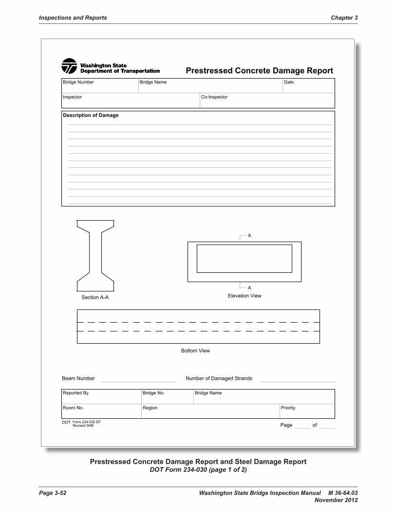
Inspections and Reports Chapter 3
Page 3-52 Washington State Bridge Inspection Manual M 36-64.03 November 2012
Steel Damage Report
DOT Form 234-030 EF Revised 9/98 Page of
Bridge Number Bridge Name Date
Inspector Co-Inspector
Description of Damage
Member Sizes
Reported By Bridge No. Bridge Name
Room No. Region Priority
DOT Form 234-030 EFRevised 9/98
Prestressed Concrete Damage Report
Page of
Bridge Number Bridge Name Date
Inspector Co-Inspector
Description of Damage
Section A-A
Bottom View
Elevation View
A
A
Reported By Bridge No. Bridge Name
Room No. Region Priority
Beam Number Number of Damaged Strands
Prestressed Concrete Damage Report and Steel Damage ReportDOT Form 234-030 (page 1 of 2)

Chapter 3 Inspections and Reports
Washington State Bridge Inspection Manual M 36-64.03 Page 3-53 November 2012
Steel Damage Report
DOT Form 234-030 EFRevised 9/98 Page of
Bridge Number Bridge Name Date
Inspector Co-Inspector
Description of Damage
Member Sizes
Reported By Bridge No. Bridge Name
Room No. Region Priority
DOT Form 234-030 EFRevised 9/98
Prestressed Concrete Damage Report
Page of
Bridge Number Bridge Name Date
Inspector Co-Inspector
Description of Damage
Section A-A
Bottom View
Elevation View
A
A
Reported By Bridge No. Bridge Name
Room No. Region Priority
Beam Number Number of Damaged Strands
Prestressed Concrete Damage Report and Steel Damage ReportDOT Form 234-030 (page 2 of 2)

Inspections and Reports Chapter 3
Page 3-54 Washington State Bridge Inspection Manual M 36-64.03 November 2012
1
Bridge Inspection Pre-Activity Safety Plan Cover Sheet
This pre-activity safety plan covers all bridge inspection activities as indicated below for the
WEEK/WEEKEND OF ________________ TO _______________.
LOCATION: BR NOs & MPs _________________________________________________.
COUNTIES _________________________________________________________________.
Our signatures below indicate that we have read the safety plan, that we understand the hazards related to the activities to be conducted, and that we will apply the appropriate controls to minimize the risks of accident and injury during the inspections.
LEAD INSPECTOR: DATE:
CO-INSPECTOR: DATE:
UBIT DRIVER: DATE:
Our initials below indicate that we have discussed and aware of the hazards, risks and control measures prior to the start of daily activities (Tail Gate Safety Meetings)
DATE
LEAD INSPECTOR
CO-INSPECTOR
UBIT DRIVER
Activities to be conducted during the above inspection dates (check all that apply):□ General Bridge Inspection Activities
□ Routine Inspection□ Damage Inspection □ Short Span Inspection□ Safety Inspection□ Interim Inspection□ Special Inspection
□ UBIT / Equipment Bridge Inspection using a UBIT, Bucket Truck, Man Lift, or other Boom Truck
□ Attach Fall Protection Plan
□ Confined Space Entry□ Attach Confined Entry Plan
□ Bridge Climbing Inspection□ Attach Fall Protection Plan
□ Scour Site Visit Bridge Inspection □ Underwater Inspection □ Boat Inspection □ Nondestructive Testing
□ □Fill out the cover page to the Pre-Activity Safety Plan for each inspection trip. For multiple crew inspections fill out a sheet for each crew. For multiple bridges where more room is needed to list the bridges above attach a list of the bridges. This cover sheet must be filled out before the activities starts and must be present on site during the activities. Maintain these coversheets in chronological order in front of the Pre-Activity Safety Plan section of the Safety Binder and keep in the inspection vehicle. The lead inspector is responsible for all on site safety matters.
Pre-Activity Safety Plan (PASP) – Cover Sheet

Chapter 3 Inspections and Reports
Washington State Bridge Inspection Manual M 36-64.03 Page 3-55 November 2012
DOT Form 750-001 EFRevised 06/08
Emergency Action PlanFirst Aid / CPR
Names of Trained Personnel on Site
Location of First Aid Equipment
Describe Procedure for Removal of Injured Employee(Note: No removal will be attempted without supervision of qualified emergency rescue personnel)
Initiate Emergency Services (call or radio 911 if available)
Location of Phone Phone Number of Sheriff or Police Phone No. of Emergency Resp. Team
Crane
Hoist
Winch
Block / Tackle
Location
Location
Location
Location
Other (Describe)
Plan Reviewed at Job Site
Employee Signature
Employee Signature
Employee Signature
Employee Signature
A Copy of This Work Plan Must Be On Job Site
Fall Protection Plan
DOT Form 750-001 EF Revised 06/08
Date Location Supervisor
Description of Work
Recognized Fall HazardsLaddersFormingCatwalksSloped AccessWork over WaterScaffold
PouringWelding at HeightSet GirdersLeading EdgeBridge DecksExcavations
Drilling ShaftsConnect GirdersWork DecksWalkways / RampsStressingTieback Strands
Perimeter Edge, Stairwell,
Method of ProtectionCrane Boom Truck Forklift Other
Personnel Hoisting
Roof, Window Opening
Assembly, disassembly, and maintenance of all equipment will be done according to manufacturer’s recommended procedures.A visual inspection of all safety equipment will be done daily or before each use.Any defective equipment will be tagged and removed from service immediately.
Procedure for Assembly, Maintenance, Inspection, and Disassembly of System
Type of Harness
Type of Lanyard
Anchorage
Control Zones/WarningLines and Monitors
Fall Restraint
Guardrail
Nets
Other
Yes No
Yes No
Type of Harness
Type of Lanyard
Type of Life Line
Anchorage
Deceleration Device
Other Type ofEquipment Used
Yes No
Fall Arrest
Overhead ProtectionHard Hats
4 inch Toe Boards
Warning Signs
Debris Nets
Other
Tool Handling, Storage, and Securing4 inch Toe Boards
Debris Nets
Tool Buckets
Other
Tool Belts
Fall Protection Plan – Emergency Action PlanDOT Form 750-001 (page 1 of 2)

Inspections and Reports Chapter 3
Page 3-56 Washington State Bridge Inspection Manual M 36-64.03 November 2012
DOT Form 750-001 EFRevised 06/08
Emergency Action PlanFirst Aid / CPR
Names of Trained Personnel on Site
Location of First Aid Equipment
Describe Procedure for Removal of Injured Employee(Note: No removal will be attempted without supervision of qualified emergency rescue personnel)
Initiate Emergency Services (call or radio 911 if available)
Location of Phone Phone Number of Sheriff or Police Phone No. of Emergency Resp. Team
Crane
Hoist
Winch
Block / Tackle
Yes No
Yes No
Yes No
Yes No
Location
Location
Location
Location
Other (Describe)
Plan Reviewed at Job Site Yes No
Employee Signature
Employee Signature
Employee Signature
Employee Signature
A Copy of This Work Plan Must Be On Job Site
Fall Protection Plan
DOT Form 750-001 EFRevised 06/08
Date Location Supervisor
Description of Work
Recognized Fall Hazards
Method of Protection
Personnel Hoisting
Roof, Window Opening
Assembly, disassembly, and maintenance of all equipment will be done according to manufacturer’s recommended procedures.A visual inspection of all safety equipment will be done daily or before each use.Any defective equipment will be tagged and removed from service immediately.
Procedure for Assembly, Maintenance, Inspection, and Disassembly of System
Type of Harness
Type of Lanyard
Anchorage
Control Zones/WarningLines and Monitors
Fall Restraint
Guardrail
Nets
Other
Type of Harness
Type of Lanyard
Type of Life Line
Anchorage
Deceleration Device
Other Type ofEquipment Used
Fall Arrest
Overhead Protection Tool Handling, Storage, and Securing
Fall Protection Plan – Emergency Action PlanDOT Form 750-001 (page 2 of 2)

Chapter 3 Inspections and Reports
Washington State Bridge Inspection Manual M 36-64.03 Page 3-57 November 2012
DO
TFo
rm 7
50-0
60 E
FR
evis
ed 1
0/20
11
Dat
eP
roje
ct L
ocat
ion
*Sup
ervi
sor/C
ompe
tent
Per
son
Des
crip
tion
of W
ork
(e.g
. equ
ipm
ent u
sed,
mat
eria
ls in
volv
ed, s
peci
al p
roce
dure
s/pr
actic
es, r
espo
nsib
ilitie
s)
Torc
h bu
rnin
g
Riv
et b
ustin
g
Man
ual d
emol
ition
of s
truct
ures
Man
ual s
crap
ing
Man
ual s
andi
ngH
eat g
un a
pplic
atio
nsP
ower
tool
s cl
eani
ng w
ith d
ust
Spr
ay p
aint
ing
with
lead
pai
nt.
Insp
ectio
nsA
ny it
em n
ot li
sted
Full-
face
PA
PR
(tig
ht fi
tting
)H
ood
or h
elm
et P
AP
R w
ith m
anuf
actu
rer
Full-
face
airl
ine
resp
irato
r in
cont
inuo
us
Prio
r rem
oval
with
tool
equ
ippe
d
Ven
tilat
ion
(mec
hani
cal)
Em
ploy
ee ro
tatio
n to
dis
tribu
te le
ad
Dus
t sup
pres
sion
/wet
met
hods
Prio
r rem
oval
with
che
mic
al s
tripp
er
Enc
apsu
latio
n
Oth
er, d
escr
ibe:
Any
of t
he re
spira
tors
list
ed a
bove
Full-
face
resp
irato
rH
ood
or h
elm
et P
AP
RH
alf-f
ace
airli
ne re
spira
tor i
n co
ntin
uous
Any
of t
he re
spira
tors
list
ed a
bove
Hal
f-fac
e re
spira
tor
DO
TFo
rm 7
50-0
60 E
F
Rev
ised
10/
2011
Lead
Exp
osur
e C
ontr
olW
ork
Plan
No.
of P
eopl
e on
Cre
w
*Sup
ervi
sor/C
ompe
tent
Per
son
mea
ns o
ne w
ho is
cap
able
of i
dent
ifyin
g ex
istin
g an
d pr
edic
tabl
e le
ad h
azar
ds in
the
surr
ound
ing
or w
orki
ng c
ondi
tions
and
who
has
auth
oriz
atio
n to
take
pro
mpt
cor
rect
ive
mea
sure
s to
elim
inat
e th
em.
Cut
ting
Wel
ding
Abr
asiv
e bl
astin
g
Lead
bur
ning
Pow
er to
ol c
lean
ing
Usi
ng le
ad c
onta
inin
g
Abr
asiv
e bl
astin
g en
clos
ure
Whe
n le
ad is
pre
sent
if d
oing
thes
e “tr
igge
r tas
ks” (
chec
k al
lth
at a
pply
)
Trea
t as
ifex
pose
d at
this
leve
l1
≥2,
500
µg/m
3(5
0 tim
es th
e P
EL
or m
ore)
≥50
0 µg
/m3
(10
times
the
PE
L or
mor
e)
≥50
µg/
m3
to 5
00 µ
g/m
3
Con
tact
you
r saf
ety
offic
efo
r gui
danc
e pr
ior t
o jo
b
Use
app
ropr
iate
resp
irato
ry p
rote
ctio
nfo
r exp
osur
e le
vel
(che
ck p
rote
ctio
n us
ed)
2
with
out d
ust c
olle
ctio
nsy
stem
s
mor
tar
mov
emen
t and
rem
oval
colle
ctio
n sy
stem
s
conf
irmed
AP
F of
100
0
flow
or p
ositi
ve p
ress
ure
mod
e
flow
or p
ositi
ve p
ress
ure
mod
e
Con
tact
the
safe
ty o
ffice
prio
r to
job
Met
hods
to R
educ
e/C
ontro
l Lea
dE
xpos
ure
(che
ck a
ll th
at a
pply
) .3
If yo
u ha
ve re
cent
air
mon
itorin
g on
a s
imila
r job
(e.g
. tas
ks, e
quip
men
t, en
viro
nmen
tal c
ondi
tions
, pai
nt le
ad c
onte
nt),
you
can
use
that
to d
eter
min
e ex
posu
re.
Oth
er a
ppro
pria
te o
ptio
ns m
ay b
e av
aila
ble.
Con
tact
you
r saf
ety
offic
e fo
r mor
e in
form
atio
n. A
PF =
ass
igne
d pr
otec
tion
fact
or (s
ee W
AC
296
-842
-130
05)
1 2
with
dus
t con
trol
expo
sed
wor
k
All
feas
ible
con
trol o
ptio
ns m
ust b
e im
plem
ente
d to
redu
ce e
xpos
ures
bel
ow th
e P
EL.
If r
espi
rato
rs a
re th
e on
ly m
etho
d us
ed to
redu
ce e
xpos
ures
,de
scrib
e in
det
ail w
hy o
ther
con
trols
are
not
feas
ible
. 3 Req
uire
men
ts fo
r all
lead
wor
k
All
item
s be
low
are
als
o re
quire
d if
expo
sure
s ar
e at
or a
bove
the
PE
L (5
0 m
icro
gram
s pe
r cub
ic m
eter
of a
ir) o
r doi
ng tr
igge
r tas
ks w
ith n
om
onito
ring
with
in p
revi
ous
12 m
onth
s sh
owin
g ex
posu
res
are
belo
w th
e P
EL
shift
and
pla
ced
in s
eale
d an
d la
bele
d ba
g or
oth
er c
onta
iner
that
will
pre
vent
dis
pers
ion
of d
ust.
Cov
eral
ls o
r oth
er e
xpos
ed g
arm
ents
mus
t nev
er b
e ta
ken
hom
e.
1. 2.A
s re
quire
d by
trig
ger t
ask
leve
lR
ecen
t air
mon
itorin
g: d
ivid
e ai
r mon
itorin
g re
sults
by
assi
gned
pro
tect
ion
fact
or o
f res
pira
tor.
(Res
ults
/AP
F=
) Ans
wer
mus
t be
belo
w 5
0
All
empl
oyee
s on
job
site
mus
t sig
n th
e le
ad c
ontro
l pla
n
Sup
ervi
sor/C
ompe
tent
Per
son
Prin
ted
Nam
eD
ate
Sig
ned
Sup
ervi
sor/C
ompe
tent
Per
son
Sig
natu
re
Lead Exposure Control Work PlanDOT Form 750-060 (page 1 of 2)

Inspections and Reports Chapter 3
Page 3-58 Washington State Bridge Inspection Manual M 36-64.03 November 2012
DO
TFo
rm 7
50-0
60 E
FR
evis
ed 1
0/20
11
Dat
eP
roje
ct L
ocat
ion
*Sup
ervi
sor/C
ompe
tent
Per
son
Des
crip
tion
of W
ork
(e.g
. equ
ipm
ent u
sed,
mat
eria
ls in
volv
ed, s
peci
al p
roce
dure
s/pr
actic
es, r
espo
nsib
ilitie
s)
DO
TFo
rm 7
50-0
60 E
F
Rev
ised
10/
2011
Lead
Exp
osur
e C
ontr
olW
ork
Plan
No.
of P
eopl
e on
Cre
w
*Sup
ervi
sor/C
ompe
tent
Per
son
mea
ns o
ne w
ho is
cap
able
of i
dent
ifyin
g ex
istin
g an
d pr
edic
tabl
e le
ad h
azar
ds in
the
surr
ound
ing
or w
orki
ng c
ondi
tions
and
who
has
auth
oriz
atio
n to
take
pro
mpt
cor
rect
ive
mea
sure
s to
elim
inat
e th
em.
Whe
n le
ad is
pre
sent
if d
oing
thes
e “tr
igge
r tas
ks” (
chec
k al
lth
at a
pply
)
Trea
t as
ifex
pose
d at
this
leve
l1
≥2,
500
µg/m
3(5
0 tim
es th
e P
EL
or m
ore)
≥50
0 µg
/m3
(10
times
the
PE
L or
mor
e)
≥50
µg/
m3
to 5
00 µ
g/m
3
Con
tact
you
r saf
ety
offic
efo
r gui
danc
e pr
ior t
o jo
b
Use
app
ropr
iate
resp
irato
ry p
rote
ctio
nfo
r exp
osur
e le
vel
(che
ck p
rote
ctio
n us
ed)
2
with
out d
ust c
olle
ctio
nsy
stem
s
mor
tar
mov
emen
t and
rem
oval
colle
ctio
n sy
stem
s
conf
irmed
AP
F of
100
0
flow
or p
ositi
ve p
ress
ure
mod
e
flow
or p
ositi
ve p
ress
ure
mod
e
Con
tact
the
safe
ty o
ffice
prio
r to
job
Met
hods
to R
educ
e/C
ontro
l Lea
dE
xpos
ure
(che
ck a
ll th
at a
pply
) .3
If yo
u ha
ve re
cent
air
mon
itorin
g on
a s
imila
r job
(e.g
. tas
ks, e
quip
men
t, en
viro
nmen
tal c
ondi
tions
, pai
nt le
ad c
onte
nt),
you
can
use
that
to d
eter
min
e ex
posu
re.
Oth
er a
ppro
pria
te o
ptio
ns m
ay b
e av
aila
ble.
Con
tact
you
r saf
ety
offic
e fo
r mor
e in
form
atio
n. A
PF =
ass
igne
d pr
otec
tion
fact
or (s
ee W
AC
296
-842
-130
05)
1 2
with
dus
t con
trol
expo
sed
wor
k
All
feas
ible
con
trol o
ptio
ns m
ust b
e im
plem
ente
d to
redu
ce e
xpos
ures
bel
ow th
e P
EL.
If r
espi
rato
rs a
re th
e on
ly m
etho
d us
ed to
redu
ce e
xpos
ures
,de
scrib
e in
det
ail w
hy o
ther
con
trols
are
not
feas
ible
. 3
All
empl
oyee
s tra
ined
in le
ad-s
afe
wor
k pr
actic
esS
oap,
wat
er (d
rinki
ng w
ater
qua
lity)
, and
tow
els
avai
labl
e an
d us
ed b
efor
e ea
ting,
drin
king
, sm
okin
g, o
r oth
er "h
and
to fa
ce" a
ctiv
ities
on s
ite o
rat
faci
lity
no fu
ther
than
thre
e m
inut
es a
way
Are
a fo
r lun
ch a
nd b
reak
s th
at is
free
of l
ead
cont
amin
atio
n. L
ist l
ocat
ion:
All
empl
oyee
s ha
ve b
een
offe
red/
had
acce
ss to
initi
al b
lood
test
ing
Oth
er P
PE
(as
appl
icab
le) g
love
s, h
ardh
at, w
eldi
ng g
love
s, w
ork
boot
s, e
ye p
rote
ctio
n/he
arin
g pr
otec
tion
No
eatin
g, d
rinki
ng, s
mok
ing,
or o
ther
han
d to
face
act
iviti
es c
ondu
cted
in le
ad w
ork
zone
Equ
ipm
ent,
tool
s, w
ork
surfa
ces
whe
re le
ad d
ust m
ay a
ccum
ulat
e ar
e cl
eane
d w
ith H
EP
A v
acuu
m a
nd/o
r wet
cle
anin
g m
etho
ds a
t end
of
shift
proj
ect
Job
will
be
rout
inel
y in
spec
ted
by S
uper
viso
r/Com
pete
nt p
erso
nA
ir m
onito
ring
has
been
pre
form
ed in
the
last
12
mon
ths
on s
imila
r job
or w
ill b
e tre
ated
as
"trig
ger t
ask"
exp
osur
es le
vels
list
ed o
n pr
evio
us p
age
Req
uire
men
ts fo
r all
lead
wor
k
All
item
s be
low
are
als
o re
quire
d if
expo
sure
s ar
e at
or a
bove
the
PE
L (5
0 m
icro
gram
s pe
r cub
ic m
eter
of a
ir) o
r doi
ng tr
igge
r tas
ks w
ith n
om
onito
ring
with
in p
revi
ous
12 m
onth
s sh
owin
g ex
posu
res
are
belo
w th
e P
EL
Cov
eral
ls: w
orn
durin
g al
l lea
d w
ork,
rem
oved
or H
EP
A v
accu
med
bef
ore
ente
ring
lunc
h/br
eak
area
or l
eavi
ng w
ork
site
, and
rem
oved
at e
nd o
fsh
ift a
nd p
lace
d in
sea
led
and
labe
led
bag
or o
ther
con
tain
er th
at w
ill p
reve
nt d
ispe
rsio
n of
dus
t. C
over
alls
or o
ther
exp
osed
gar
men
ts m
ust n
ever
be
take
n ho
me.
Res
pira
tory
pro
tect
ion
used
sel
ecte
d ba
sed
on e
ither
:1. 2.
As
requ
ired
by tr
igge
r tas
k le
vel
Rec
ent a
ir m
onito
ring:
div
ide
air m
onito
ring
resu
lts b
y as
sign
ed p
rote
ctio
n fa
ctor
of r
espi
rato
r. (R
esul
ts/A
PF=
) A
nsw
er m
ust b
e be
low
50
Em
ploy
ees
med
ical
ly c
lear
ed fo
r res
pira
tor u
se a
nd fi
t tes
ted
All
empl
oyee
s on
job
site
mus
t sig
n th
e le
ad c
ontro
l pla
n
Sup
ervi
sor/C
ompe
tent
Per
son
Prin
ted
Nam
eD
ate
Sig
ned
Sup
ervi
sor/C
ompe
tent
Per
son
Sig
natu
re
Lead Exposure Control Work PlanDOT Form 750-060 (page 2 of 2)

Chapter 3 Inspections and Reports
Washington State Bridge Inspection Manual M 36-64.03 Page 3-59 November 2012
Name Employee ID Number Organization Code
Supervisor's Name Telephone Number
ExposureWelding/Cutting/BrazingSpray PaintingVehicle Body RepairPavement Marking
LeadPestcidesAsbestosSilica
SolventsBridge MaintenanceAbrasive BlastingGrinding/Sanding
Pigeon DroppingsOther (Specify)
Fit TestDate of Fit Test Type of Fit Test Used
Tester
Qualitative Quantitative N/A
Pass Fail
RespiratorSize
Facepiece
Type
Manufacturer
Model Number Approval Number
Small Medium Large
1/2 Mask Full Face Hood/Helmet
SCBAPAPRAir LineDust / MistOther (Describe)
Chemical CartridgeGas MaskCombination
NorthMSAWillsonSurvivair3MBullard
NorthstarAmerican OpticalScottGlendaleUvexOther
Comments
DOT Form 750-090 EFRevised 02/2012
Respirator Record
Respirator RecordDOT Form 750-090

Inspections and Reports Chapter 3
Page 3-60 Washington State Bridge Inspection Manual M 36-64.03 November 2012
DOT Form 750-094 EFRevised 08/2011
Sampling Equipment Name Model/Type Date Calibrated Identification Number
Emergency ServicesEmergency services must be arranged prior to permit-required confined space entry (including 911 services). Onlypersons who have been trained and equipped for entry rescue may enter the space to perform rescue services. Do notattempt an entry rescue if you are not trained and equipped to do so. If a person is down for no apparent cause, you mustassume that toxic gases or an oxygen deficiency exist.
Post entry review of permit conducted by
Confined Space Entry PermitLocation, Description and Classification of Confined Space
DOT Form 750-094 EFRevised 08/2011
Date Purpose of Entry/Work to be done Time Started
Division/Unit Time Completed
Supervisor(s) in Charge of Crew Type of Crew Phone
Requirements Completed (All applicablemust be completed before entry)Lockout - De-energize
Line(s) Broken, Capped or Blanked
Purge, Flush, and Vent Ventilation
Standby Safety Personnel
Full Body Harness with “D” Ring
First Aid/CPR Equipment & TrainedPersonnel
Secure area (post, flag and protectfrom falling objects)
Emergency Escape/Retrieval/Rescue/EquipmentLifelines
Protective Clothing
Respirator (list type)Hot Work Permit
Atmospheric ChecksPeriodic ChecksAcceptable
ConditionsInitial
ChecksChecks After Isolation and
Ventilation% of OxygenL.E.L.Carbon MonoxideHydrogen Sulfide
19.5% to 23%< 10%
< 35 ppm
Hr 1 Hr 2 Hr 3 Hr 4 Hr 5 Hr 6 Hr 7 Hr 8
Atmospheric monitoring conducted by:
Note: continuous/periodic tests shall be performed throughout the job. Contact Region Safety Office with questions.
L.E.L. Lower Explosive Limit, also referred to as lower flammable limit (LFL).
Distribution: Original to Division/Unit, Copy to Regional Safety Office
< 10 ppm
Completed N/A
Lighting (explosion proof as necessary)
Communication Equipment
Completed N/A
Add any other requirements necessary for entry
_
Records must be maintained for at least one year.
Date
1
Hazards in Confined SpaceCheck all that apply and ensure each hazard is eliminated or controlled before and during entry:
(Potentially) Hazardous atmosphereMaterial with potential to engulfElectrical shockMoving partsTemperature extremes
which slopes downwards and tapers to a smaller section)
Communication procedures between entrants and attendants
Emergency/Rescue Service Provided by
Phone Number/Contact Information
Describe Procedures (include necessary equipment):
Print Name Initial Authorized Role 2
2 Check the person’s authorized role. Remember, a person cannot be both an attendant and entrant; they can only serveone role.
Entry Supervisor Authorization - All Entry Conditions SatisfiedSignature Date
Permit expiration date and time (may not be longer than required to perform work)
Post entry reviews must be done within one year of entry.Distribution: Original to Division/Unit, Copy to Regional Safety Office
Trapping or asphyxiation hazard (inwardly coverging walls or floor
Any Other hazard that is capable of impairing self rescue or presentsimmediate danger to life or health (describe):
Date Time
Requirements Completed (All applicablemust be completed before entry)
1
Confined Space Entry and Hot Work PermitDOT Form 750-094 (page 1 of 2)

Chapter 3 Inspections and Reports
Washington State Bridge Inspection Manual M 36-64.03 Page 3-61 November 2012
DOT Form 750-094 EFRevised 08/2011
Sampling Equipment Name Model/Type Date Calibrated Identification Number
Emergency ServicesEmergency services must be arranged prior to permit-required confined space entry (including 911 services). Onlypersons who have been trained and equipped for entry rescue may enter the space to perform rescue services. Do notattempt an entry rescue if you are not trained and equipped to do so. If a person is down for no apparent cause, you mustassume that toxic gases or an oxygen deficiency exist.
Post entry review of permit conducted by
Confined Space Entry PermitLocation, Description and Classification of Confined Space
DOT Form 750-094 EFRevised 08/2011
Date Purpose of Entry/Work to be done Time Started
Division/Unit Time Completed
Supervisor(s) in Charge of Crew Type of Crew Phone
Requirements Completed (All applicablemust be completed before entry)Lockout - De-energize
Line(s) Broken, Capped or Blanked
Purge, Flush, and VentVentilation
Standby Safety Personnel
Full Body Harness with “D” Ring
First Aid/CPR Equipment & TrainedPersonnel
Secure area (post, flag and protectfrom falling objects)
Emergency Escape/Retrieval/Rescue/EquipmentLifelines
Protective Clothing
Respirator (list type)Hot Work Permit
Atmospheric ChecksPeriodic ChecksAcceptable
ConditionsInitial
ChecksChecks After Isolation and
Ventilation% of OxygenL.E.L.Carbon MonoxideHydrogen Sulfide
19.5% to 23%< 10%
< 35 ppm
Hr 1 Hr 2 Hr 3 Hr 4 Hr 5 Hr 6 Hr 7 Hr 8
Atmospheric monitoring conducted by:
Note: continuous/periodic tests shall be performed throughout the job. Contact Region Safety Office with questions.
L.E.L. Lower Explosive Limit, also referred to as lower flammable limit (LFL).
Distribution: Original to Division/Unit, Copy to Regional Safety Office
< 10 ppm
Completed N/A
Lighting (explosion proof as necessary)
Communication Equipment
Completed N/A
Add any other requirements necessary for entry
_
Records must be maintained for at least one year.
Date
1
Hazards in Confined SpaceCheck all that apply and ensure each hazard is eliminated or controlled before and during entry:
which slopes downwards and tapers to a smaller section)
Communication procedures between entrants and attendants
Emergency/Rescue Service Provided by
Phone Number/Contact Information
Describe Procedures (include necessary equipment):
Print Name Initial Authorized Role 2
Entrant Attendant
Entrant Attendant
Entrant Attendant
Entrant Attendant
Entrant Attendant
Entrant Attendant
Entrant Attendant2 Check the person’s authorized role. Remember, a person cannot be both an attendant and entrant; they can only serve
one role.
Entry Supervisor Authorization - All Entry Conditions SatisfiedSignature Date
Permit expiration date and time (may not be longer than required to perform work)
Post entry reviews must be done within one year of entry.Distribution: Original to Division/Unit, Copy to Regional Safety Office
immediate danger to life or health (describe):
Date Time
Requirements Completed (All applicablemust be completed before entry)
1
Confined Space Entry and Hot Work PermitDOT Form 750-094 (page 2 of 2)

Inspections and Reports Chapter 3
Page 3-62 Washington State Bridge Inspection Manual M 36-64.03 November 2012
UT INSPECTION REPORT
Bridge Name:Bridge No:Structure ID:Structure Type:Agency:Milepost:
Inspected items:
Procedures:
Sh. No. Contract Sh. Name
UTM Location
Date: Hours:Inspector ID #:
Co-Inspector Intials:Lead Inspector Intials:
Rivet Server PlansUTM Per Girder or
Truss LineUTM Type
Pins1. When possible, test from both ends of pins.2. Verify pin length shown on back reflection with plans. If back reflection does not match the plans, conduct
manual length measurement and document correct pin length.3. Start test with transducer at or near pin center for back reflection check, then run transducer around full
perimeter of pin, searching for indications or significant loss of back reflection.4. Whenever the test suggests that there is a defect in a pin, store and print out the indication with all
associated equipment and settings documented. The location of the transducer shall also be documented using a clock hand convention (1 O’clock to 12 O’clock).
Note: UTM = Ultrasonic Tested Member
Ultrasonic (UT) Inspection Report.xlsx 1 of 2
Ultrasonic UT Inspection Report(page 1 of 2)

Chapter 3 Inspections and Reports
Washington State Bridge Inspection Manual M 36-64.03 Page 3-63 November 2012
<
<<<<
<<<
LE
FT E
ND
>
>>>>
>>>
<
<<<<
<<<
R
IGH
T EN
D
>>>
>>>>
>C
OM
ME
NTS
:C
OM
ME
NTS
:
DAT
E
d =
in.
D =
in.
in.
S le
ft =
in.
S ri
ght =
in.
H =
in.
h =
in.
9:00
3:00
6:00
12:0
0
9:00
3:00
6:00
12:0
0
LEFT
EN
DFA
CE
RIG
HT
EN
D
FAC
E
PR
OFI
LE L
OO
KIN
G A
HE
AD
ON
STA
TIO
N
LOO
KIN
G
STR
UC
TUR
E I.D
.TR
USS
or G
IRD
ER
PIN
I.D
.To
tal L
engt
h, L
= Ultr
ason
ic (U
T) In
spec
tion
Rep
ort.x
lsx
2 of
2
Ultrasonic UT Inspection Report(page 2 of 2)

Inspections and Reports Chapter 3
Page 3-64 Washington State Bridge Inspection Manual M 36-64.03 November 2012
UT
INSP
ECTI
ON
SC
HED
ULE
Dat
e:H
ours
:In
spec
tor I
D #
:Le
ad In
spec
tor:
Co-
Insp
ecto
r:
VTU
TLo
catio
nFr
eq.
(Mon
ths)
UT
Insp
ectio
n D
ate
Brid
ge N
ame:
Mile
post
:
Con
ditio
n St
ate
Trus
s /
Gird
erSp
an
Brid
ge N
o.:
Stru
ctur
e ID
:St
ruct
ure
Type
:A
genc
y:
Det
ail D
escr
iptio
nR
edun
dant
N
ext
Insp
ectio
nD
ate
UT
Insp
ectio
n S
ched
ule.
xlsx
1 of
1
UT Inspection Schedule

Chapter 3 Inspections and Reports
Washington State Bridge Inspection Manual M 36-64.03 Page 3-65 November 2012
PIN
S SU
MM
AR
Y SH
EET
2005
2007
2009
2011
2013
2015
2017
2019
2021
Con
ditio
n St
ate
Brid
ge N
o.:
Stru
ctur
e ID
:H
ours
:
Lead
Insp
ecto
r:
Brid
ge N
ame:
Dat
e:
Trus
s /
Gird
erLo
catio
n
Age
ncy:
Insp
ecto
r ID
#:
Stru
ctur
e Ty
pe:
Co-
Insp
ecto
r:M
ilepo
st:
Det
ail D
escr
iptio
n
Pin
s S
umm
ary
She
et.x
lsx
1 of
1
Pins Summary Sheet

Inspections and Reports Chapter 3
Page 3-66 Washington State Bridge Inspection Manual M 36-64.03 November 2012
PIN AND HANGER VISUALINSPECTION REPORT
Bridge Name:Bridge No:Structure ID:Structure Type:Agency:Milepost:
Inspected Items: Pins & Hanger Assemblies
Procedures:
Co-Inspector Signature:
Hours:Date:
Co-Inspector Intials:
Lead Inspector Signature:
Inspector ID #:Lead Inspector Intials:
Hangers1. As required, use mirrors or other equipment to check inside surfaces of members.2. Check for loose or unevenly loaded member sub-elements.3. Check all rivets at connection plates, with emphasis on first row. The first row is the row closest to the edge
of the connection or gusset plate.4. Check for any welds, including plug, tack, or repair welds. Record location of welds, regardless of condition,
and document weld type and category.5. Check members and associated connection or gusset plates for areas of heavy or pitted corrosion, nicks,
gouges, sharp bends, and collision damage. Record location of all these conditions and estimated sectionloss, if applicable.
6. Check all heat straightened or repaired areas. Record location of these areas, regardless of condition.
Pins and Anchor Bolts1. As required, use mirrors or other equipment to check inside surfaces of members.2. Check for pitting, laminar rust, surface deformation, and pack rust. It is important to check the pin, pin nuts,
and all members surrounding the pin for this kind of steel deterioration.3. Check for mobility and noise of pin and surrounding members. If the pin is physically “frozen” it is important
to note this because the added stress can affect other members in the structure.4. Observe and record abnormalities like; alignment, pin wear, loose pin nuts, and amount of nut engagement.
It’s important to note that full nut engagement is when the nut is flush with the pin or the pin is extendingh
Pin and Hanger Visual Inspection Report.xlsx 1 of 2
Location Type
MemberPer Girder or Truss
Line Sh. No.
Rivet Server Plans
Contract Sh. Name
4. Observe and record abnormalities like; alignment, pin wear, loose pin nuts, and amount of nut engagement.It’s important to note that full nut engagement is when the nut is flush with the pin or the pin is extendingpast the nut.
5. Check for paint system failure on pin nuts, pin, and surrounding members.
Pin and Hanger Visual Inspection Report.xlsx 1 of 2
Pin and Hanger Visual Inspection Report(page 1 of 2)

Chapter 3 Inspections and Reports
Washington State Bridge Inspection Manual M 36-64.03 Page 3-67 November 2012
PIN
AN
D H
AN
GER
VIS
UA
LIN
SPEC
TIO
N R
EPO
RT
Dat
e:H
ours
:In
spec
tor I
D #
:Le
ad In
spec
tor:
Co-
Insp
ecto
r:
Trus
s /
Gird
erSp
anLo
catio
nFe
atur
eIn
spec
ted
Det
ail D
escr
iptio
nR
emar
ksPi
ns
Han
gers
Age
ncy:
Mile
post
:
Stru
ctur
e Ty
pe:
Stru
ctur
e ID
:B
ridge
No.
:B
ridge
Nam
e:
Pin
and
Han
ger V
isua
l Rep
ort F
orm
.xls
2 of
2
Pin and Hanger Visual Inspection Report(page 2 of 2)

Inspections and Reports Chapter 3
Page 3-68 Washington State Bridge Inspection Manual M 36-64.03 November 2012
SPECIAL FEATURESINSPECTION REPORT
Bridge Name:Bridge No:Structure ID:Structure Type:Agency:Milepost:
Inspected items:
Procedures:
Note: FCM = Fracture Critical Member
Special Features Specail Features TypeFCM Per Girder or
Truss Line
Date:Hours:Inspector ID #:
Contract
Co-Inspector Intials:
Lead Inspector Signature:
Lead Inspector Intials:
Co-Inspector Signature:
Sh. No.
Rivet Server Plans
Sh. Name
Special Features Inspection Report.xlsx 1 of 2Special Features Inspection Report.xlsx 1 of 2
Special Features Inspection Report(page 1 of 2)

Chapter 3 Inspections and Reports
Washington State Bridge Inspection Manual M 36-64.03 Page 3-69 November 2012
SPEC
IAL
FEA
TUR
ESIN
SPEC
TIO
N R
EPO
RT
Dat
e:H
ours
:In
spec
tor I
D #
:Le
ad In
spec
tor:
Co-
Insp
ecto
r:
Gird
erPi
erLo
catio
nFe
atur
eIn
spec
ted
Det
ail D
escr
iptio
nR
emar
ks
Brid
ge N
o.:
Brid
ge N
ame:
Mile
post
:A
genc
y:St
ruct
ure
Type
:St
ruct
ure
ID:
Spe
cial
Fea
ture
s In
spec
tion
Rep
ort.x
lsx
2 of
2
Special Features Inspection Report(page 2 of 2)

Inspections and Reports Chapter 3
Page 3-70 Washington State Bridge Inspection Manual M 36-64.03 November 2012
Vertical Clearance Card

Chapter 3 Inspections and Reports
Washington State Bridge Inspection Manual M 36-64.03 Page 3-71 November 2012
VERTICAL CLEARANCE REPAIR REQUIRED
Bridge ____________________ Milepost___________________ Date__________________
Vertical clearance posting requirements for this bridge require Bridge Maintenance to coordinate with the Region Traffic Office to establish requirements and complete the repair.
Vertical clearances were checked and found to be_________________ minimum at: ______________________________________________________________________________________________ ______________________________________________________________________________________________. Bridge is not posted or is incorrectly posted for _______________. New or revised posting of the structure is required. Prior to any fabrication of signs, verify these findings and report any discrepancies more than 1” to the Bridge Geometry Engineer at 360-570-2544. Once actual minimum vertical clearance and location has been verified, posted clearance height is to be 3” lower than actual measured clearance and displayed to the nearest inch. Post the bridge for the following clearance or clearances and at the following locations___________________ ____________________________________________________________________________________________________________________________________________________________________________________________ ______________________________________________________________________ (See Posting Bullet Below)
Bridge is correctly posted for _________________ minimum at: ______________________________________ ______________________________________________________________________________________________ _____________________________________________, but requires additional posting. (See Posting Bullet Below)
Posting at bridges where the actual measured clearance is less than 15’ 3”, requires:
The LOW CLEARANCE (W12-301) sign, or the LOW CLEARANCE w/ARROW (W12-302) sign at the low point on the structure.
The advance LOW CLEARANCE (W12-2) sign on the right shoulder or both shoulders for multiple lane divided routes. Distance of posting from the structure is to be in accordance with MUTCD Table 2C-4.
Posted clearance is less than 14 feet and requires installation of additional advance LOW CLEARANCE (W12-2) sign in advance of the closest intersecting road or off ramp that provides a detour around the low clearance obstruction. Supplement with an ADVISORY DISTANCE (W13-501) plaque showing the distance to the obstruction. Distance of posting from intersection is to be in accordance with MUTCD Table 2C-4.
Where the clearance varies, such as at arched structures or tunnels, use additional signs to provide effective clearance information at the following locations: ______________________________________________________ ____________________________________________________________________________________________________________________________________________________________________________________________
Posting at shoulder, over edge of lane or fog line, requires advance LOW CLEARANCE posting on same shoulder to read “LOW CLEARANCE AT SHOULDER __________. Distance of posting from the structure is to be in accordance with MUTCD Table 2C-4.
Existing posting is not required based on measured clearance greater than 15’ 3”, Posting is discretionary. However, changes in the structure or surface overlays may have reduced the actual clearance since posting was established. Verify clearance and remove or change the posting accordingly.
All regulatory and vertical clearance postings are to be in accordance with RCWs 46.61.450, 46.44.020, WSDOT Traffic Manual M51-02 (Chapter 2) and the MUTCD. Contact Bridge Preservation Supervisor at 360-570-2557 with any questions or noted discrepancies.
Vertical Clearance Repair Required
Inspections and Reports Chapter 3
Page 3-72 Washington State Bridge Inspection Manual M 36-64.03 November 2012
3.06 AppendicesAppendix 3.06-A1 Bridge With Fill on DeckAppendix 3.06-A2 Bridge With No Fill on DeckAppendix 3.06-A3 Culvert With Fill on DeckAppendix 3.06-B UBIT Inspections and ProceduresAppendix 3.06-C FHWA Letter for Routine Extended Frequency InspectionsAppendix 3.06-D FHWA Letter for Bridge Special Feature Inspections

Washington State Bridge Inspection Manual M 36-64.03 Page 3.06-A1-1 November 2012
Appendix 3.06-A1 Bridge With Fill on Deck
Short Span Inspections are recommended and performed by the Washington State Department of Transportation (WSDOT) Bridge Preservation Office when the following criteria are met:
1. Depth of fill must be less than D/2 (where D = Maximum opening distance).
2. CONCRETE Structures: Opening of 6 feet or more. STEEL Structures: Opening of 6 feet or more. TIMBER Structures: Opening of 4 feet or more.

Bridge With Fill on Deck Appendix 3.06-A1
Page 3.06-A1-2 Washington State Bridge Inspection Manual M 36-64.03 November 2012

Washington State Bridge Inspection Manual M 36-64.03 Page 3.06-A2-1 November 2012
Appendix 3.06-A2 Bridge With No Fill on Deck
Short Span Inspections are recommended and performed by the Washington State Department of Transportation (WSDOT) Bridge Preservation Office when the following criteria are met:
1. CONCRETE Structures: Opening of 6 feet or more. STEEL Structures: Opening of 6 feet or more. TIMBER Structures: Opening of 4 feet or more.

Bridge With No Fill on Deck Appendix 3.06-A2
Page 3.06-A2-2 Washington State Bridge Inspection Manual M 36-64.03 November 2012

Washington State Bridge Inspection Manual M 36-64.03 Page 3.06-A3-1 November 2012
Appendix 3.06-A3 Culvert With Fill on Deck
Short Span Inspections are recommended and performed by the Washington State Department of Transportation (WSDOT) Bridge Preservation Office when the following criteria are met:
1. Depth of fill must be less the D/2 (where D = total opening).
2. Total Opening of 8 feet or more.

Culvert With Fill on Deck Appendix 3.06-A3
Page 3.06-A3-2 Washington State Bridge Inspection Manual M 36-64.03 November 2012

Washington State Bridge Inspection Manual M 36-64.03 Page 3.06-B-1 November 2012
Appendix 3.06-B UBIT Inspections and Procedures
The following explains the procedures for UBIT inspections.
1. Determine Those Bridges Which Will Require Inspection With a UBIT – On some structures, the team leader will not be able to gain sufficient access to determine the structural condition of the member (for example, floorbeam and stringer connections, a pier cap, or a bearing device at midspan or on top of interior piers that are too high for ladders). If this is the case, a UBIT, ladder, scaffolding, catwalk, boat, or some other means may be required to provide sufficient access.
The records for all structures that require inspection with a UBIT are all contained within the State Bridge Inventory. As part of scheduling for an upcoming inspection season, lists are generated from the inventory for bridges that are due for inspection with a UBIT.
2. Provide for the Use of the UBIT – The UBIT is an expensive piece of equipment and only a few agencies have the budget to purchase one. Along with the State, there are only a few UBIT owners in the Pacific Northwest. These trucks are complicated pieces of equipment which require special expertise to operate and a trained UBIT driver to drive and maintain the truck.
3. Conduct the UBIT Inspection – The UBIT inspection gives “hands on” access to under bridge elements for inspection. The team leader should make the same observations and assessments as would be made during a routine inspection. Given the expense of contracting for the use of this equipment, special care should be taken to ensure that the UBIT inspection is performed efficiently.
It is a good idea to map out an inspection plan that will allow an inspection of the entire under portion of the bridge in as few steps as possible and with as few changes in the positioning of the UBIT as needed. Communication between the inspection team in the bucket and the truck operator should be maintained at all times to ensure the safety of the operation and to allow for proper positioning for the inspection. The team should have any and all inspection equipment required (test hammer, note pad, camera, etc.). Finally, the team leader should ensure that needed traffic control can be provided and that all other necessary special equipment will be available. If these steps are taken, the UBIT inspection can be accomplished quickly and at minimum expense.
4. Record the Inspection Findings on the Bridge Inspection Report – The UBIT inspection findings should be recorded on the Bridge Inspection Report. Follow the same procedures as described for Routine Inspection Reports in Section 3.02.A.
5. Updating the WSBIS Inventory Record – Any other changes needed for the WSBIS Inventory Record (add the inspection date for UBIT, Fracture Critical, and/or Special Inspections) should be entered into BridgeWorks.
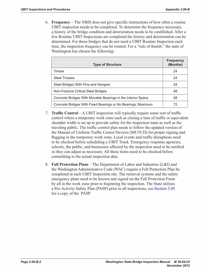
UBIT Inspections and Procedures Appendix 3.06-B
Page 3.06-B-2 Washington State Bridge Inspection Manual M 36-64.03 November 2012
6. Frequency – The NBIS does not give specific instructions of how often a routine UBIT inspection needs to be completed. To determine the frequency necessary, a history of the bridge condition and deterioration needs to be established. After a few Routine UBIT Inspections are completed the history and deterioration can be determined. For those bridges that do not need a UBIT Routine Inspection each time, the inspection frequency can be rotated. For a “rule of thumb,” the state of Washington has chosen the following:
Type of StructureFrequency (Months)
Timber 24
Steel Trusses 24
Steel Bridges With Pins and Hangers 24
Non-Fracture Critical Steel Bridges 48
Concrete Bridges With Movable Bearings in the Interior Spans 48
Concrete Bridges With Fixed Bearings or No Bearings; Maximum 72
7. Traffic Control – A UBIT inspection will typically require some sort of traffic control where a temporary work zone such as closing a lane of traffic or equivalent shoulder width is set up to provide safety for the inspection team as well as the traveling public. The traffic control plan needs to follow the updated version of the Manual of Uniform Traffic Conrol Devices (MUTCD) for proper signing and flagging in the temporary work zone. Local events and traffic disruptions need to be checked before scheduling a UBIT Truck. Emergency response agencies, schools, the public, and businesses affected by the inspection need to be notified so they can adjust as necessary. All these items need to be checked before committing to the actual inspection date.
8. Fall Protection Plans – The Department of Labor and Industries (L&I) and the Washington Administrative Code (WAC) require a Fall Protection Plan be completed at each UBIT Inspection site. The retrieval systems and the safety emergency plans need to be known and signed on the Fall Protection Form by all in the work zone prior to beginning the inspection. The State utilizes a Pre-Activity Safety Plan (PASP) prior to all inspections, see Section 3.05 for a copy of the PASP.

Washington State Bridge Inspection Manual M 36-64.03 Page 3.06-C-1 November 2012
FHWA Letter for Routine Appendix 3.06-C Extended Frequency Inspections

FHWA Letter for Routine Extended Frequency Inspections Appendix 3.06-C
Page 3.06-C-2 Washington State Bridge Inspection Manual M 36-64.03 November 2012

Washington State Bridge Inspection Manual M 36-64.03 Page 3.06-D-1 November 2012
FHWA Letter for Bridge Appendix 3.06-D Special Feature Inspections

FHWA Letter for Bridge Special Feature Inspections Appendix 3.06-D
Page 3.06-D-2 Washington State Bridge Inspection Manual M 36-64.03 November 2012

Appendix 3.06-D FHWA Letter for Bridge Special Feature Inspections
Washington State Bridge Inspection Manual M 36-64.03 Page 3.06-D-3 November 2012

FHWA Letter for Bridge Special Feature Inspections Appendix 3.06-D
Page 3.06-D-4 Washington State Bridge Inspection Manual M 36-64.03 November 2012

Appendix 3.06-D FHWA Letter for Bridge Special Feature Inspections
Washington State Bridge Inspection Manual M 36-64.03 Page 3.06-D-5 November 2012

FHWA Letter for Bridge Special Feature Inspections Appendix 3.06-D
Page 3.06-D-6 Washington State Bridge Inspection Manual M 36-64.03 November 2012

Washington State Bridge Inspection Manual M 36-64.03 Page 4-1November 2012
Chapter 4 WSDOT Bridge Elements
4.0 IntroductionThis chapter defi nes the Washington State Department of Transportation (WSDOT) elements for recording the structural condition evaluation of bridges. Local Agencies are encouraged, but not required to use the WSDOT Bridge Elements as defi ned in this chapter in order to use WSDOT management strategies and lessons learned. The basic intent of any element data is to supplement the National Bridge Inventory (NBI) structural evaluation of the Deck, Superstructure, and Substructure. Most of the other NBI information such as location, traffi c, and geometry is still useful, but element conditions are a practical necessity to identify and manage bridge needs.
Though the NBIS did provide a consistent standard for the collection of bridge data, it was not comprehensive enough to provide performance-based decision support that included economic considerations. Among the problems with the NBIS are:
• Each bridge is divided into only three major parts for condition assessment: superstructure, substructure, and deck. This level of detail is not suffi cient to identify appropriate repair strategies, or to estimate costs.
• Each of the three major parts was rated on a 0-9 scale by severity of deterioration, without identifying the deterioration process at work or the extent of deterioration.
• NBI condition ratings vary based on the vague language of the condition defi nitions. Because the bridges include multiple distress symptoms and ratings to describe the overall or “average” condition of the bridge, is often diffi cult to decide what the “average” condition is when a bridge has mainly localized problems.
• A suffi ciency rating based on NBI data is used at the Federal level for funding approval, but this measure emphasizes large-scale functional and geometric characteristics of bridges, making it irrelevant for maintenance decision-making.
• NBI does not provide a method to inspect or track the performance of items such as paint, overlays, and expansion joints.
WSDOT recognized a different strategy towards future bridge preservation was needed in the early 1980’s. A comprehensive deck testing program existed at the time and obviously the testing should have a connection to the NBI deck condition rating. WSDOT elements have been in use since 1992 and were designed to be practical for the inspector, useful to a bridge manager, and accurately capture bridge conditions. WSDOT elements have matured since 1992 and so have the national element philosophies:
• 1985 – NCHRP Project 12-28: Bridgit and Pontis Management software • 1987 – NCHRP Report 300: Element based Bridge Management System (BMS) • 1993 – FHWA CoRe Element Report recommendations• 1996 – AASHTO CoRe Element Guidelines adopted• 2011 – AASHTO Guidelines for Bridge Element Inspection

WSDOT Bridge Elements Chapter 4
Page 4-2 Washington State Bridge Inspection Manual M 36-64.03 November 2012
Today, a successful Bridge Management System must use supplemental bridge condition data to ensure the effective use of available funds. WSDOT element data has supported WSDOT Bridge needs with minor changes since the year 2008 in the follow ways:
• Element data is used to identify current bridge condition, need, and cost.
• Provided a logical and realistic method to prioritize bridge projects.
• Realistic and reliable forecasts of future preservation need and cost.
• Adapted changes in management philosophies without changing elements.
• Tracks the performance of desired bridge needs.
Elements represent parts of a structure that are relevant to document structural conditions with clearly defi ned condition states or to manage. Elements that carry primary design loads are considered structural elements and all follow the same condition state philosophy.
“Smart Flags” are elements used to track supplemental information that may or may not be included in other elements or exist at the time of original construction. A Smart Flag condition states defi ned as necessary to collect useful information and may be signifi cantly different than other element defi nitions. Examples of Smart Flags are Steel Fatigue (cracks in steel elements), Scour, and Pack Rust.
4.01 Identifying Elements Prior to Inspection
Details about the design of the bridge are important when identifying the elements. As-built plans should be used to determine the correct elements, and then fi eld verifi ed during the inspection. If as-built plans are not available, then the elements will have to be defi ned or assumed at the bridge site. Many of the element dimensions for the element total quantity are diffi cult to determine in the fi eld and it is highly recommend the total quantities be calculated based on contract plan dimensions.
For example, looking at the contract Plans is the only practical way to determine if a bridge deck has plain reinforced steel which is element 12, or epoxy coated steel which is element 26 because this information is not visible to the inspector. Likewise, fi eld measuring the deck length and width in traffi c would not be necessary and usually less accurate than if plan dimensions are available.
An average bridge made of the same material will have six to ten elements. A large or complex bridge may have up to 20 elements. A typical bridge will have a bridge deck, possibly a deck overlay, bridge rails, a primary load carrying member like a prestressed concrete girder, primary substructure support like concrete columns, other elements like abutments, expansion joints and/or bearings.

Chapter 4 WSDOT Bridge Elements
Washington State Bridge Inspection Manual M 36-64.03 Page 4-3November 2012
4.02 Element Units and the Total Quantity
Every element has assigned units that are necessary for the inspector to quantify the element defects. The units are “SF” for Square Feet, “LF” for Lineal Feet, “EA” for Each, or in the case of concrete pontoons the units are per Cell.
“SF” units apply to elements where the surface area provides the better method to document element condition and manage the element, such as deck and paint elements.
The total quantity for an element with “LF” units should represent the total length of an element and is based on the way it was constructed. For example: A bridge may have been built using fi ve “Prestressed Concrete Girders.” Each one was individually pre-cast and then put into place at the bridge site. If each girder were 100 feet in length then the total element quantity would be “500 LF.” If the same bridge was a “Concrete Box Girder” then the total quantity would be “100 LF” since the box girder was constructed as one unit.
“EA” units are used to determine the number of members in a condition state. For example: A bridge may 5 piles at 3 piers for a total quantity of 15 for the pile element. Then, each pile is inspected, evaluated, and recorded in the appropriate condition state. Elements with units of “EA” code the entire member in one condition state, such as piles, where the entire pile is in one of the defi ned condition states. Other element units, such as “LF” or “SF” may have all or portions of the element in one or all of the condition states in order to describe the existing element conditions.
4.03 Quantifying Element Defects
In order to quantify the condition of an element, the fi rst step is to review the condition state language for the elements. A complete list of the condition state descriptions is provided in this chapter and summarized in this section.
Element condition state (CS) language is based on four condition states for all primary structural members, regardless of the materials. Similar to the NBI system of evaluation, element condition requires the inspector to evaluate defects and also quantify the defect’s impact to the element or possibly the bridge. A defect evaluation may result in element quantities in CS1, CS2, CS3, or CS4 depending on the location, size, structural importance or element units.
The following summarizes the WSDOT element condition state philosophy for primary structural members. Different condition philosophies apply to the non-primary structural elements such as deck/overlays, joints, paint, and smart fl ags. These element condition states are described in Chapter 4 and not discussed in this section.
Condition State 1: Good Condition – Most parts of a bridge will be in this condition state for all BMS elements. The element may have some defects, but is in good condition. Many times new bridges have insignifi cant defects and older bridges will acquire insignifi cant defects with time. In order to determine if the defect is insignifi cant, the inspector must decide if the defect will impact the element load carrying capacity with time. Inspectors are cautioned to look at new construction that may not be CS1.

WSDOT Bridge Elements Chapter 4
Page 4-4 Washington State Bridge Inspection Manual M 36-64.03 November 2012
Condition State 2: Repaired Condition – This condition state documents repairs to structural members. A repair is defi ned as a defective member partially modifi ed to carry design loads and still dependent on the remaining portions of the defective member, such as an in-span splice, helper member, or column splice. Generally, these are easy to identify and report. Common repairs do not have the same integrity or longevity as original construction. When a damaged or defective member has been entirely replaced, the member quantity is CS1 or considered a new member. Many times members are diffi cult to access and prohibit a good quality repair. Inspectors are cautioned to verify repairs to make sure they are functioning as intended. If a repair is not completed correctly or is not functioning properly, then the repair should be coded as CS3 or CS4. For example:
• A timber helper stringer/pile that does not properly transfer design loads is not considered suffi cient to be considered in CS2. A repair must be properly blocked, braced, or connected to the deck/pile as required by repair design.
• Timber pier caps are assumed to be designed as simple spans. Even though the member that has been partially replaced is not continuous at a support, as long as there is a positive connection to the supporting columns, the replaced portion may be considered in CS1.
Condition State 3: Fair Condition – This condition state records any signifi cant defect noticed by the inspector, but the defect does not signifi cantly impact the capacity of the element. Capacity is not currently threatened, but if left unchecked, it could be threatened in the future. Repairs may apply to the elements in CS3 because the defects are more economical address now than to wait and repair later.
Condition State 4: Poor Condition – This condition state documents members with defects that have impacted the structural capacity of the element. Based on the visual inspection, the owner of the bridge must address this defi ciency in order to preserve or restore the capacity of the member and/or structure. Generally, these defects have reduced the structural capacity of the element, but are still within safe operating limits of design.

Chapter 4 WSDOT Bridge Elements
Washington State Bridge Inspection Manual M 36-64.03 Page 4-5November 2012
4.04 Concrete Element Cracking
The following table is reproduced from the Bridge Inspector’s Reference Manual (BIRM), Volume 1, Table 2.2.3; and should be used to distinguish between different sizes of concrete cracks.
Concrete Crack With GuidelinesReinforced Concrete Prestressed Concrete
English Metric English MetricHairline (HL) < 1/16″ < 1.6 mm < 0.004″ < 0.1 mm
(0.0625)
Narrow (N) 1/16″ to 1/8″ 1.6 to 3.2 mm 0.004″ to 0.009″ 0.1 to 0.23 mm
0.0625″ to 0.125″
Medium (M) 1/8″ to 3/16″ 3.2 to 4.8 mm 0.010″ to 0.030″ 0.25 to 0.75 mm
0.125″ to 0.1875″
Wide (W) > 3/16″ > 4.8 mm > 0.030″ > 0.76 mm
> 0.1875″
Concrete Structural Cracking – For the purpose of evaluating element condition, concrete structural cracks are narrow (or wider) in regions of high shear or moment (see BIRM). Crack width is signifi cant to the extent that it indicates exposure of rebar to water and/or a structural problem in a concrete element. Generally, most concrete elements have hairline cracking and not considered signifi cant structurally.
4.05 WSDOT Deck Element to NBI Deck Table
WSDOT began testing concrete decks in the early 1980s and discovered a very poor correlation to the traditional assumptions of deck deterioration. In addition, the deck testing and crack surveys did not prioritize deck preservation projects in a fashion acceptable to the inspectors, maintenance, or management. Today, WSDOT recommends the use of the deck and soffi t elements and Table 4.0 to evaluate the FHWA Item 058, NBI Deck Overall Condition Code. This table originates from the 1973 FHWA Coding Guidelines and has been modifi ed to refl ect WSDOT’s primary bridge deck management philosophies since the early 1990s.
Secondary and more subjective concrete deck conditions such as cracking, scaling, leaching, rebar cover, chloride content, Half-cell potential, etc. may be documented in the deck element notes, but not applied to the deck element evaluation of structural condition. These secondary conditions are applied during annual prioritization of the concrete bridge decks and should not determine the NBI code. To be clear, these types of secondary conditions visible below the deck in the soffi t or other structural elements below the deck element require an evaluation of:

WSDOT Bridge Elements Chapter 4
Page 4-6 Washington State Bridge Inspection Manual M 36-64.03 November 2012
Percent of Concrete Deck Patches, Spalls,
and Delaminations(CS2 + CS3 + CS4)
Percent of Concrete Deck Soffi t in CS3
(CS3 only)NBI Deck
Condition Code
N/A N/A 9
None None 8
None None 7
< 1% < 2% 6
1% to 2% 2% to 5% 5
2% to 5% 5% to 10% 4
> 5% > 10% 3
WSDOT Deck Condition to NBI Deck Overall Table 4.0
4.1 Bridge DecksThe intent of the bridge deck elements is to record the top surface deterioration. The Concrete Deck Soffi t, slab, or deck-girder elements record the structural deterioration. Deck elements 12, 13, 14, 20, and 26 record deck patches in CS2, deck spalls in CS3, and delaminations in CS4. Other deck top surface distress such as cracking, scaling, and rutting are not tracked in the deck BMS condition states. These items should be described in the notes at the inspector’s discretion. Do not count fi lling in of the rut as a patch. These locations have fi lled in a rut with Liquid Concrete or Ure-Fast and are not considered a deck structural repair.
All asphaltic patching material on a concrete bridge deck shall be considered a spalled area and since this is unacceptable patching material. These materials can be picked out of the spall and will smell like tar.
All bridges will have at least one deck element, even though some bridges do not have a traditional deck and use elements 13 or 14. (The one exception is a Luten Arch structure that is earth fi lled with an asphalt pavement only.)
Traditional concrete bridge decks use elements 12, 20, or 26 to record the top surface deterioration; and have the Structural Concrete Deck Element (35) to record the structural deterioration. It should be noted for element 26 that epoxy coated rebar in bridge decks became an industry standard in Washington State in the early 1980s.
Non-Traditional concrete decks use elements 13 or 14 to record the top surface deterioration and the slab or deck-girder elements record the structural deterioration.
Steel and Timber decks use elements 28, 29, 30, 31 to record structural condition only, since there is little need to track the wearing surface defects.

Chapter 4 WSDOT Bridge Elements
Washington State Bridge Inspection Manual M 36-64.03 Page 4-7November 2012
Inspectors are encouraged to take the time to locate and describe the patches and spalls on larger structures using photos and descriptions. The preferred documentation format for patching is the number and SF per span. This format is easiest for the next inspector to identify quantity changes.
Quantity estimates must be based on the sum of the estimated length and width of the patched or spalled areas. Approximations based on the percent of area are not useful. The total quantity for deck elements is the actual bridge deck area. Do not use the FHWA Item 051 when a deck curb-to-curb dimensions vary.
12 Concrete Deck Units – SF
This element defi nes a concrete bridge deck constructed with uncoated steel reinforcement. The quantity should equal the deck’s curb-to-curb width times the length.
1. Defects are superfi cial. The deck surfaces have no spalls/delaminations or previous repairs. The deck surfaces may have hairline cracks or rock pockets. Wear and rutting may expose aggregate or reinforcing.
2. Deck area with repairs or patches. Do not include the rare case rutting fi lled with patching material.
3. Deck area with spalling.
4. If the results of deck delamination testing are available, record the delaminated area (CS4) from element 376 in the deck CS4.
Elem 13- Bridge Deck Surface
Deck Bulb Tee Girders
Asphalt Overlay
Voided Slab Units
Elem 14- Fully Supported Concrete Deck
13 Bridge Deck Surface Units – SF
This element defi nes a surface of a bridge deck that consists of a slab or girder without a traditional deck. Usually there is a deck protection system (overlay) present, but in some cases, traffi c may be driving directly on the girder or slab. The Bridge Deck Surface consists of precast or prestressed girders with no span between the fl anges. This element is generally used with superstructure elements 38, 49, 50, 51, 52, 54, 108, 109, or 114. The quantity should equal the “deck” curb-to-curb width times the length.

WSDOT Bridge Elements Chapter 4
Page 4-8 Washington State Bridge Inspection Manual M 36-64.03 November 2012
14 Fully Supported Concrete Deck Units – SF
This element defi nes a fully supported concrete bridge deck constructed with one layer of coated reinforcement (epoxy, galvanizing, stainless steel, etc.). The bridge support surface consists of precast or prestressed girders with no span between the fl anges. This element may apply to superstructure elements 50, 51, 108, 109, or 114. The quantity should equal the deck’s curb-to-curb width times the length.
1. Defects are superfi cial. The deck surfaces have no spalls/delaminations or previous repairs. The deck surfaces have no exposed reinforcing. The deck surfaces may have hairline cracks, rock pockets and/or be worn exposing aggregate.
2. If the top of the slabs or girders are visible, area of deck with repairs.
3. If the top of the slabs or girders are visible, area of deck spalling
4. If the results of deck delamination testing are available, record the delaminated area (CS4) from element 376 in the deck CS4.
20 Concrete Deck – Lightweight Aggregate Units – SF
This element defi nes a lightweight concrete bridge deck constructed with lightweight aggregate and steel reinforcement. The total design weight of the deck is approximately 120 lbs./C.Y. The quantity should equal the deck’s curb-to-curb width times the length.
26 Concrete Deck w/Coated Bars Units – SF
This element defi nes a concrete bridge deck constructed with coated (epoxy, galvanizing, stainless steel, etc.) reinforcement. The quantity should equal the deck’s curb-to-curb width times the length.
1. Defects are superfi cial. The deck surfaces have no spalls/delaminations or previous repairs. The deck surfaces may have hairline cracks or rock pockets. Wear and rutting may expose aggregate or reinforcing.
2. Deck area with repairs or patches. Do not include the rare case rutting fi lled with patching material.
3. Deck area with spalling.
4. If the results of deck delamination testing are available, record the delaminated area (CS4) from element 376 in the deck CS4.

Chapter 4 WSDOT Bridge Elements
Washington State Bridge Inspection Manual M 36-64.03 Page 4-9November 2012
27 Steel Orthotropic Deck Units – SF
This element defi nes a bridge deck constructed of a fl at, deck plate stiffened either longitudinally or transversely, or in both directions. See BIRM, Volume 1, Figure P.1.2.7. The quantity should equal the deck’s curb-to-curb width times the length.
28 Steel Deck – Open Grid Units – SF
This element defi nes a bridge deck constructed of steel grids that are open and unfi lled. The quantity should equal the deck’s curb-to-curb width times the length.
29 Steel Deck – Concrete Filled Grid Units – SF
This element defi nes a bridge deck constructed of steel grids with either all of the openings or just those in the wheel lines fi lled with concrete. The quantity should equal the deck’s curb-to-curb width times the length.
30 Deck – Corrugated or Other Steel system Units – SF
This element generally defi nes a bridge deck constructed of corrugated metal fi lled with Portland cement concrete or asphaltic concrete. This element may also be used to identify other non-standard steel decks. The quantity should equal the deck’s curb-to-curb width times the length.
1. Defects are superfi cial. The connectors (such as welds, rivets, etc.) or concrete/asphalt fi ller are functioning as designed.
2. Deck area with repairs or replaced panels.
3. Deck area with structural defects. The defects do not signifi cantly affect structural capacity. Defi ciencies do not warrant analysis, but may require repairs.
4. Deck area with damage in signifi cant locations or quantity and has reduced the structural capacity of the element. Structural analysis is warranted or has determined repairs are essential to restore the full capacity of the element.

WSDOT Bridge Elements Chapter 4
Page 4-10 Washington State Bridge Inspection Manual M 36-64.03 November 2012
31 Timber Deck Units – SF
This element defi nes a bridge deck constructed of timber. The deck may be longitudinally or transversely laminated or of planks. The deck may have an overlay or may be constructed with runners of metal or timber. The quantity should equal the deck’s curb to curb width times the length.
1. Defects are superfi cial and have no effect on the structural capacity of the element. Decay, insect infestation, cracks, splits, or checks may exist.
2. Timber deck area with repairs, plates, or replaced timbers.
3. Timber deck area with structural defects. The defects do not signifi cantly affect structural capacity. Defi ciencies do not warrant analysis, but may require repairs. These areas are typically marked with a YELLOW TAG by inspectors.
4. Timber deck area with damage in signifi cant locations or quantity and has reduced the structural capacity of the element or the bridge. Structural analysis is warranted or has determined repairs are essential to restore the full capacity of the element. These areas are typically marked with a RED TAG by inspectors.
32 Fiber Reinforced Polymer (FRP) – Deck Units – SF
This element defi nes a bridge deck constructed of fi ber reinforced polymer. The quantity should equal the deck’s curb to curb width times the length.
1. Defects are superfi cial. Cracking or delamination of layers may be present.
2. FRP Deck area with repairs, patches, or plated.
3. FRP Deck area with structural defects. The defects do not signifi cantly affect structural capacity. Defi ciencies do not warrant analysis, but may require repairs.
4. FRP Deck area with damage in signifi cant locations or quantity and has reduced the structural capacity of the element or the bridge. Structural analysis is warranted or has determined repairs are essential to restore the full capacity of the element.
35 Concrete Deck Soffi t Units – SF
This element defi nes the bottom (or undersurface) and edge of a concrete deck and is to be included with concrete deck elements 12, 20, and 26. It is extremely valuable when an asphalt overlay exists on the top surface of the deck. The purpose of the element is to identify decks that may have a reduced structural capacity through visual inspections of the deck soffi t. Element 35 does not apply if steel stay-in-place forms are present on the soffi t. To be consistent with the deck quantity, the deck soffi t quantity should equal the deck’s curb-to-curb width times the length.
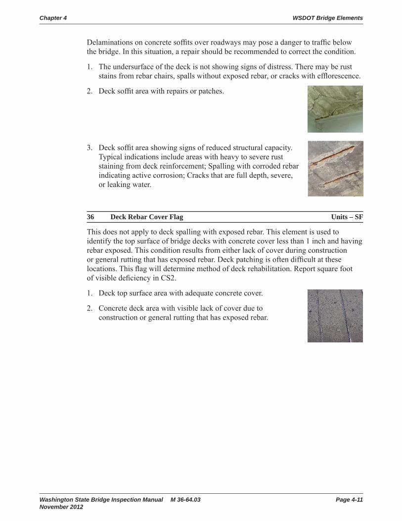
Chapter 4 WSDOT Bridge Elements
Washington State Bridge Inspection Manual M 36-64.03 Page 4-11November 2012
Delaminations on concrete soffi ts over roadways may pose a danger to traffi c below the bridge. In this situation, a repair should be recommended to correct the condition.
1. The undersurface of the deck is not showing signs of distress. There may be rust stains from rebar chairs, spalls without exposed rebar, or cracks with effl orescence.
2. Deck soffi t area with repairs or patches.
3. Deck soffi t area showing signs of reduced structural capacity. Typical indications include areas with heavy to severe rust staining from deck reinforcement; Spalling with corroded rebar indicating active corrosion; Cracks that are full depth, severe, or leaking water.
36 Deck Rebar Cover Flag Units – SF
This does not apply to deck spalling with exposed rebar. This element is used to identify the top surface of bridge decks with concrete cover less than 1 inch and having rebar exposed. This condition results from either lack of cover during construction or general rutting that has exposed rebar. Deck patching is often diffi cult at these locations. This fl ag will determine method of deck rehabilitation. Report square foot of visible defi ciency in CS2.
1. Deck top surface area with adequate concrete cover.
2. Concrete deck area with visible lack of cover due to construction or general rutting that has exposed rebar.

WSDOT Bridge Elements Chapter 4
Page 4-12 Washington State Bridge Inspection Manual M 36-64.03 November 2012
4.2 SuperstructureGirders
A girder is defi ned as any longitudinal structural member (single web or box section) that directly supports the bridge deck. A girder type bridge will typically have two or more girders. Girders may be constructed of the following typical materials: Rolled, welded, bolted (riveted), steel sections; Post tensioned, prestressed or reinforced concrete sections; or Timber sections.
Elem #92
Steel Welded Girder Prestressed Conc Girder
Elem #115
Timber Sawn Girder
Elem #117
Diaphragms
Diaphragms are structural members used to tie adjoining girders together to improve the strength and rigidity of the girder and to distribute forces in the lateral direction. There is no BMS element defi ned for a diaphragm. If a diaphragm has advanced deterioration, it should be noted in the BMS comments of the accompanying girder.
Pedestrian Bridges
The same BMS elements used for bridges that carry vehicular traffi c can be used for pedestrian bridges. Do not use the BMS sidewalk elements (#260 through #266) for pedestrian bridges.
Elem 140 Pedestrian Bridge
Girders
Diaphragm
Elem 108

Chapter 4 WSDOT Bridge Elements
Washington State Bridge Inspection Manual M 36-64.03 Page 4-13November 2012
Slab Bridges
Slab bridges can have precast segments or cast in place concrete. The bridge in the picture is a cast in place concrete slab and will have a deck element for the deterioration of the top surface. Structural defi ciencies of the slab bottom and edge are documented in BMS element #38 “Concrete Slab.”
38 Concrete Slab Units – SF
This element defi nes a concrete slab bridge and edge that has been constructed with uncoated reinforcement. Structural defi ciencies of the edge and bottom surface are addressed in the condition states. The slab quantity should equal the slab’s curb-to-curb width times the length.
49 Concrete Hollow Slab Units – SF
This element defi nes a concrete slab bridge and edge that has been constructed with sono-tubes and uncoated reinforcement. Structural defi ciencies of the edge and bottom surface are addressed in the condition states. This type of bridge was typically built in the 50’s and 60’s on the state highway system. The slab quantity should equal the slab’s curb-to-curb width times the length.
50 Prestressed Concrete Slab Units – SF
This element defi nes a concrete slab bridge that has been constructed with prestressed concrete and uncoated steel reinforcement. Structural defi ciencies of the edge and bottom surface are addressed in the condition states. The slab quantity should equal the slab’s curb-to-curb width times the length.
51 Prestressed Concrete Slab w/Coated Bars Units – SF
This element defi nes a concrete slab bridge that has been constructed with prestressed concrete and coated steel reinforcement (epoxy, etc.). This element may be solid or have built in voids. Structural defi ciencies of the edge and bottom surface are addressed in the condition states. The slab quantity should equal the slab’s curb-to-curb width times the length.
52 Concrete Slab w/Coated Bars Units – SF
This element defi nes a concrete slab bridge and edge that has been constructed with coated (epoxy, etc.) reinforcement. This element may or may not contain a hollow core. Structural defi ciencies of the edge and bottom surface are addressed in the condition states. The slab quantity should equal the slab’s curb-to-curb width times the length.
Elem 38
Concrete Slab

WSDOT Bridge Elements Chapter 4
Page 4-14 Washington State Bridge Inspection Manual M 36-64.03 November 2012
1. Defects are superfi cial and have no effect on the structural capacity of the element. There may be discoloration, effl orescence, and/or superfi cial cracking, spalls, or delaminations.
2. Concrete slab area with repairs or patches.
3. Concrete slab area with structural defects. The defects do not signifi cantly affect structural capacity. Defi ciencies do not warrant analysis, but may require repairs.
4. Concrete slab area with damage in signifi cant locations or quantity and has reduced the structural capacity of the element or the bridge. Structural analysis is warranted or has determined repairs are essential to restore the full capacity of the element.
54 Timber Slab Units – SF
This element defi nes a slab that is constructed of timber. Structural defi ciencies of the edge and bottom surface are addressed in the condition states. The slab quantity should equal the slab’s curb-to-curb width times the length.
1. Defects are superfi cial and have no effect on the structural capacity of the element. Decay, insect infestation, cracks, splits, or checks may exist.
2. Slab area with repairs, plates or replaced timbers.
3. Slab area with structural defects. The defects do not signifi cantly affect structural capacity. Defi ciencies do not warrant analysis, but may require repairs. These areas are typically marked with a YELLOW TAG by inspectors.
4. Slab area with damage in signifi cant locations or quantity and has reduced the structural capacity of the element or the bridge. Structural analysis is warranted or has determined repairs are essential to restore the full capacity of the element. These areas are typically marked with a RED TAG by inspectors.
89 Prestressed Concrete Girder w/Coated Strands Units – LF
This element defi nes a girder constructed of precast prestressed concrete and epoxy coated strand that supports the bridge deck. The element quantity should equal the sum of each girder length. The total element quantity should equal the length of each girder multiplied by the number of girders.
1. Defects are superfi cial and have no effect on the structural capacity of the element. There may be discoloration, effl orescence, and/or superfi cial cracking, spalls, or delaminations.
2. Girder length affected by repair or patch. Capacity repairs such as a strand splicing should record girder span length.

Chapter 4 WSDOT Bridge Elements
Washington State Bridge Inspection Manual M 36-64.03 Page 4-15November 2012
3. Girder length affected by defects. The defects do not signifi cantly affect structural capacity. Defi ciencies do not warrant analysis, but may require repairs. Girder with defects such as: delaminations, spalls, structural cracking, exposed or corroded reinforcing or strands.
4. Girder span length with damage in signifi cant locations or quantity and has reduced the structural capacity of the element or the bridge. Structural analysis is warranted or has determined repairs are essential to restore the full capacity of the element.
90 Steel Rolled Girder Units – LF
This element defi nes a girder unit of structural steel that has an integral web and fl anges and was fabricated in a steel mill by the rolling process. This element may have bolted, riveted or welded cover plates. This element directly supports the bridge deck and is part of a two or more longitudinal girder system. The element quantity should equal the length of each girder multiplied by the number of girders.
91 Steel Riveted Girder Units – LF
This element defi nes a girder unit of structural steel that directly supports the bridge deck. This element has a web and fl anges that are connected with rivets. This element is part of a two or more longitudinal girder system. The element quantity should equal the length of each girder multiplied by the number of girders.
92 Steel Welded Girder Units – LF
This element defi nes a girder unit of structural steel that directly supports the bridge deck. This element has a web and fl anges that are connected with welds. This element is part of a two or more longitudinal girder system. The element quantity should equal the sum of each girder length.
1. Defects are superfi cial and have no effect on the structural capacity of the element.
2. Girder length affected by repairs such as: bolts or rivets have been replaced; cracks that have been drilled or plated.
3. Girder length affected by structural defects. The defects do not signifi cantly affect structural capacity. Defi ciencies do not warrant analysis, but may require repairs. Structural defi ciencies are not limited to impact damage, cracks, broken bolts, or measurable section loss due to corrosion (note the location and depth).
4. Girder span length with damage in signifi cant locations or quantity and has reduced the structural capacity of the element or the bridge. Structural analysis is warranted or has determined repairs are essential to restore the full capacity of the element. Structural defi ciencies are not limited to impact damage, corrosion, a crack in primary load path member or in the attachment welded to primary member. Retain the quantity of the element reported in CS4 if the element is repainted but not repaired.

WSDOT Bridge Elements Chapter 4
Page 4-16 Washington State Bridge Inspection Manual M 36-64.03 November 2012
96 Concrete Encased Steel Girder Units – LF
This element defi nes a steel girder that is encased in concrete. The element quantity should equal the length of each girder multiplied by the number of girders.
1. Defects are superfi cial and have no effect on the structural capacity of the element. There may be discoloration, effl orescence, and/or superfi cial cracking.
2. Girder length affected by repairs or patches.
3. Girder length affected by structural defects. The defects do not signifi cantly affect structural capacity. Defi ciencies do not warrant analysis, but may require repairs. Structural defi ciencies are not limited to impact damage, cracks, broken bolts, or measurable section loss due to corrosion (note the location and depth), concrete delaminations or spalls in a tension zone.
4. Girder span length with damage in signifi cant locations or quantity and has reduced the structural capacity of the element or the bridge. Structural analysis is warranted or has determined repairs are essential to restore the full capacity of the element.
97 Prestressed Concrete Trapezoidal Girder Units – LF
This element defi nes a prestressed concrete box girder. Post-tensioning and span fi eld splices may or may not be present. The element quantity should equal the sum of each girder length. The total element quantity will equal the length of each girder multiplied by the number of girders.
1. Defects are superfi cial and have no effect on the structural capacity of the element. There may be discoloration, effl orescence, and/or superfi cial cracking, spalls, or delaminations.
2. Girder length affected by repair or patch. Capacity repairs such as a strand splicing should record girder span length.
3. Girder length affected by defects. The defects do not signifi cantly affect structural capacity. Defi ciencies do not warrant analysis, but may require repairs. Girder with defects such as: delaminations, spalls, structural cracking, exposed or corroded reinforcing or strands.
4. Girder span length with damage in signifi cant locations or quantity and has reduced the structural capacity of the element or the bridge. Structural analysis is warranted or has determined repairs are essential to restore the full capacity of the element.
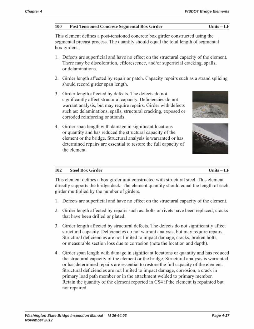
Chapter 4 WSDOT Bridge Elements
Washington State Bridge Inspection Manual M 36-64.03 Page 4-17November 2012
100 Post Tensioned Concrete Segmental Box Girder Units – LF
This element defi nes a post-tensioned concrete box girder constructed using the segmental precast process. The quantity should equal the total length of segmental box girders.
1. Defects are superfi cial and have no effect on the structural capacity of the element. There may be discoloration, effl orescence, and/or superfi cial cracking, spalls, or delaminations.
2. Girder length affected by repair or patch. Capacity repairs such as a strand splicing should record girder span length.
3. Girder length affected by defects. The defects do not signifi cantly affect structural capacity. Defi ciencies do not warrant analysis, but may require repairs. Girder with defects such as: delaminations, spalls, structural cracking, exposed or corroded reinforcing or strands.
4. Girder span length with damage in signifi cant locations or quantity and has reduced the structural capacity of the element or the bridge. Structural analysis is warranted or has determined repairs are essential to restore the full capacity of the element.
102 Steel Box Girder Units – LF
This element defi nes a box girder unit constructed with structural steel. This element directly supports the bridge deck. The element quantity should equal the length of each girder multiplied by the number of girders.
1. Defects are superfi cial and have no effect on the structural capacity of the element.
2. Girder length affected by repairs such as: bolts or rivets have been replaced; cracks that have been drilled or plated.
3. Girder length affected by structural defects. The defects do not signifi cantly affect structural capacity. Defi ciencies do not warrant analysis, but may require repairs. Structural defi ciencies are not limited to impact damage, cracks, broken bolts, or measurable section loss due to corrosion (note the location and depth).
4. Girder span length with damage in signifi cant locations or quantity and has reduced the structural capacity of the element or the bridge. Structural analysis is warranted or has determined repairs are essential to restore the full capacity of the element. Structural defi ciencies are not limited to impact damage, corrosion, a crack in primary load path member or in the attachment welded to primary member. Retain the quantity of the element reported in CS4 if the element is repainted but not repaired.

WSDOT Bridge Elements Chapter 4
Page 4-18 Washington State Bridge Inspection Manual M 36-64.03 November 2012
103 Prestressed Concrete Super Girder Units – LF
This element defi nes a prestressed WSDOT type W83G, WF83G, W95G, or WF95G girder. Girders may or may not be post-tensioned. The element quantity should equal the total length of each girder multiplied by the number of girders.
104 Post Tension Concrete Box Girder Units – LF
This element defi nes a box girder unit constructed of post-tensioned, cast in place concrete. The element quantity should equal the length of each girder multiplied by the number of girders.
105 Concrete Box Girder Units – LF
This element defi nes a box girder superstructure unit constructed with cast in place reinforced concrete. The element quantity should equal the total length of box girders.
1. Defects are superfi cial and have no effect on the structural capacity of the element. There may be discoloration, effl orescence, and/or superfi cial cracking, spalls, or delaminations.
2. Girder length affected by repair or patch. Capacity repairs such as a strand splicing should record girder span length.
3. Girder length affected by defects. The defects do not signifi cantly affect structural capacity. Defi ciencies do not warrant analysis, but may require repairs. Girder with defects such as: delaminations, spalls, structural cracking, exposed or corroded reinforcing or strands.
4. Girder length affected by damage in signifi cant locations or quantity and has reduced the structural capacity of the element or the bridge. Structural analysis is warranted or has determined repairs are essential to restore the full capacity of the element.
107 Steel Open Girder Units – LF
This element defi nes an open girder unit that is constructed of structural steel. An open or “through” girder is part of a two girder system with stringer and fl oor beam elements that support a bridge deck. Open girders are located on the outside of the bridge. The bridge deck and any sidewalks are contained between the open girders. Bridges with open girders were generally built prior to 1950 and usually have built up riveted steel members. The element quantity should equal the length of each girder multiplied by the number of girders.
1. Defects are superfi cial and have no effect on the structural capacity of the element.
2. Steel open girder length affected by repairs such as: bolts or rivets have been replaced; cracks that have been drilled or plated.

Chapter 4 WSDOT Bridge Elements
Washington State Bridge Inspection Manual M 36-64.03 Page 4-19November 2012
3. Steel open girder length affected by structural defects. The defects do not signifi cantly affect structural capacity. Defi ciencies do not warrant analysis, but may require repairs. Structural defi ciencies are not limited to impact damage, cracks, broken bolts, or measurable section loss due to corrosion (note the location and depth).
4. Steel open girder span length with damage in signifi cant locations or quantity and has reduced the structural capacity of the element or the bridge. Structural analysis is warranted or has determined repairs are essential to restore the full capacity of the element. Structural defi ciencies are not limited to impact damage, corrosion, a crack in primary load path member or in the attachment welded to primary member. Retain the quantity of the element reported in CS4 if the element is repainted but not repaired.
Open Girders
stringer floorbeam Elem #107
Steel Open Girder
108 Prestressed Concrete Bulb-T Girder Units – LF
This element defi nes a precast prestressed concrete Bulb-T girder unit. Structural defi ciencies of the edge and bottom surface are addressed in the condition states. The element quantity should equal the length of each girder multiplied by the number of girders.
109 Prestressed Concrete Multiple Web Girder Units Units – LF
This element defi nes a precast prestressed concrete girder that has more than one web. Structural defi ciencies of the edge and bottom surface are addressed in the condition states. The element quantity should equal the length of each girder unit. The total element quantity should equal the length of each girder unit multiplied by the number of girders.
110 Concrete Girder Units – LF
This element defi nes a girder (including T-Beams) constructed of non-prestressed reinforced concrete. The element quantity should equal the length of each girder multiplied by the number of girders.
1. Defects are superfi cial and have no effect on the structural capacity of the element. There may be discoloration, effl orescence, and/or superfi cial cracking, spalls, or delaminations.
2. Girder length affected by repair or patch. Capacity repairs such as a strand splicing should record girder span length.

WSDOT Bridge Elements Chapter 4
Page 4-20 Washington State Bridge Inspection Manual M 36-64.03 November 2012
3. Girder length affected by defects. The defects do not signifi cantly affect structural capacity. Defi ciencies do not warrant analysis, but may require repairs. Girder with defects such as: delaminations, spalls, structural cracking, exposed or corroded reinforcing or strands.
4. Girder span length with damage in signifi cant locations or quantity and has reduced the structural capacity of the element or the bridge. Structural analysis is warranted or has determined repairs are essential to restore the full capacity of the element.
111 Timber Glue-Lam Girder Units – LF
This element defi nes a girder unit constructed of glue-lam timber. This element directly supports the bridge deck. The element quantity should equal the length of each girder multiplied by the number of girders.
1. Defects are superfi cial and have no effect on the structural capacity of the element. Decay, insect infestation, cracks, splits, or checks may exist.
2. Glue-Lam girder length affected by repairs, patches, or plated.
3. Glue-Lam girder length affected by structural defects. The defects do not signifi cantly affect structural capacity. Defi ciencies do not warrant analysis, but may require repairs. These areas are typically marked with a YELLOW TAG by inspectors.
4. Glue-Lam girder span length with damage in signifi cant locations or quantity and has reduced the structural capacity of the girder or the bridge. Structural analysis is warranted or has determined repairs are essential to restore the full capacity of the element. These areas are typically marked with a RED TAG by inspectors.
113 Steel Stringer Units – LF
This element defi nes a stringer constructed of structural steel that supports the deck in a stringer-fl oor beam system. A stringer is connected to a fl oor beam and directly supports a bridge deck. A steel stringer and fl oor beam combination is commonly used in steel truss and steel open girder bridges. The element quantity should equal the length of each stringer multiplied by the number of stringers.
1. Defects are superfi cial and have no effect on the structural capacity of the element.
2. Stringer length affected by repairs such as: bolts or rivets have been replaced; cracks that have been drilled or plated.

Chapter 4 WSDOT Bridge Elements
Washington State Bridge Inspection Manual M 36-64.03 Page 4-21November 2012
3. Stringer length affected by structural defects. The defects do not signifi cantly affect structural capacity. Defi ciencies do not warrant analysis, but may require repairs. Structural defi ciencies are not limited to impact damage, cracks, broken bolts, or measurable section loss due to corrosion (note the location and depth).
4. Stringer span length with damage in signifi cant locations or quantity and has reduced the structural capacity of the element or the bridge. Structural analysis is warranted or has determined repairs are essential to restore the full capacity of the element. Structural defi ciencies are not limited to impact damage, corrosion, a crack in primary load path member or in the attachment welded to primary member. Retain the quantity of the element reported in CS4 if the element is repainted but not repaired.
114 Concrete Multiple Web Girder Unit Units – LF
This element defi nes a girder constructed of non-prestressed reinforced precast concrete. Structural defi ciencies of the edge and bottom surface are addressed in the condition states. The element quantity should equal the length of each unit multiplied by the number of units. Check the NBIS main span type.
115 Prestressed Concrete Girder Units – LF
This element defi nes a girder constructed of precast prestressed concrete that supports the bridge deck. The element quantity should equal the sum of each girder length. The element quantity should equal the length of each girder multiplied by the number of girders.
116 Concrete Stringer Units – LF
This element defi nes a stringer constructed of reinforced concrete that supports the bridge deck in a stringer-fl oor beam system. The element quantity should equal the length of each stringer multiplied by the number of stringers. See Steel Stringers and Floor Beams for a more general description.
1. Defects are superfi cial and have no effect on the structural capacity of the element. There may be discoloration, effl orescence, and/or superfi cial cracking, spalls, or delaminations.
2. Girder length affected by repair or patch. Capacity repairs such as a strand splicing should record girder span length.
3. Girder length affected by defects. The defects do not signifi cantly affect structural capacity. Defi ciencies do not warrant analysis, but may require repairs. Girder with defects such as: delaminations, spalls, structural cracking, exposed or corroded reinforcing or strands.
4. Girder span length with damage in signifi cant locations or quantity and has reduced the structural capacity of the element or the bridge. Structural analysis is warranted or has determined repairs are essential to restore the full capacity of the element.

WSDOT Bridge Elements Chapter 4
Page 4-22 Washington State Bridge Inspection Manual M 36-64.03 November 2012
117 Timber Sawn Girder Units – LF
This element defi nes a girder constructed of sawn timber that supports the bridge deck. The element quantity should equal the length of each girder multiplied by the number of girders.
118 Timber Stringer Units – LF
This element defi nes a stringer constructed of timber that supports the bridge deck. The element quantity should equal the length of each stringer multiplied by the number of stringers. See Steel Stringers, Element 113, for a more general description.
1. Defects are superfi cial and have no effect on the structural capacity of the element. Decay, insect infestation, cracks, splits, or checks may exist.
2. Girder or stringer length affected by repairs or plates.
3. Girder or stringer length affected by structural defects. The defects do not signifi cantly affect structural capacity. Defi ciencies do not warrant analysis, but may require repairs. Typically, locations in a load path with a 1½″ to 3″ shell thickness are marked with a YELLOW TAG.
4. Girder or stringer span length with damage in signifi cant locations or quantity and has reduced the structural capacity of the element or the bridge. Structural analysis is warranted or has determined repairs are essential to restore the full capacity of the element. Typically, locations in a load path with less than a 1½″ shell thickness are marked with a RED TAG.
119 Concrete Truss Units – LF
This element defi nes all members in a truss that is constructed of concrete. There is only one concrete truss on the state highway system. The truss quantity should equal the sum of each concrete truss length, which is two times the truss span length.
1. Truss panel length with superfi cial defects that have no effect on the structural capacity of the element. There may be discoloration, effl orescence, and/or superfi cial cracking, spalls, or delaminations.
2. Truss panel length with repairs or patches.
3. Truss panel length affected with structural defects. The defects do not signifi cantly affect structural capacity. Defects do not warrant analysis, but may require repairs. Length of truss with defects such as: delaminations, spalls, structural cracking, exposed or corroded reinforcing or strands.
4. Length of truss affected with damage in signifi cant locations or quantity and has reduced the structural capacity of the element or the bridge. Structural analysis is warranted or has determined repairs are essential to restore the full capacity of the element.

Chapter 4 WSDOT Bridge Elements
Washington State Bridge Inspection Manual M 36-64.03 Page 4-23November 2012
126 Steel Thru Truss Units – LF
This element includes all structural steel truss members. Code this element for through and pony trusses only. The truss quantity should equal the sum of each truss length, which is two times the truss span length.
131 Steel Deck Truss Units – LF
This element includes all truss members of a structural steel deck truss. The top and bottom chords are included in this element. The truss quantity should equal the sum of each truss length, which is two times the truss span length.
1. Defects are superfi cial and have no effect on the structural capacity of the element.
2. Truss panel length with repairs such as: bolts or rivets have been replaced; cracks that have been drilled or plated.
3. Truss panel length with structural defects. The defects do not signifi cantly affect structural capacity. Defi ciencies do not warrant analysis, but may require repairs. Structural defi ciencies are not limited to impact damage, cracks, broken bolts, or measurable section loss due to corrosion (note the location and depth).
4. Truss panel length affected by damage in signifi cant locations or quantity and has reduced the structural capacity of the element or the bridge. Structural analysis is warranted or has determined repairs are essential to restore the full capacity of the element. Structural defi ciencies are not limited to impact damage, corrosion, a crack in primary load path member or in the attachment welded to primary member. Retain the quantity of the element reported in CS4 if the element is repainted but not repaired.
133 Truss Gusset Plates Units – EA
This element documents structural defects on gusset plates at the panel points of a truss element. Gusset plates are defi ned as any plate attached to primary members that transfer primary or secondary load at the panel joint. Signifi cant defects should be considered when they are within the stress zones of the gusset. Stress zones are approximately illustrated as the shaded portion in Figure at right. The total quantity for a truss is the total number of upper and lower panel points on both sides of the truss.
1. Defects are superfi cial and have no effect on the structural capacity of the element.
2. Number of panel points with repairs or have been reinforced.
3. Number of panel points with structural defects. The defects do not signifi cantly affect structural capacity. Defi ciencies do not warrant analysis, but may require repairs. Structural defi ciencies are not limited to impact damage, cracks, broken bolts, or measurable section loss due to corrosion (note the location and depth).

WSDOT Bridge Elements Chapter 4
Page 4-24 Washington State Bridge Inspection Manual M 36-64.03 November 2012
4. Number of panel points with structural defi ciencies in signifi cant locations or quantity and has reduced the structural capacity of the element or the bridge. Structural analysis is warranted or has determined repairs are essential to restore the full capacity of the element. Retain the quantity of the element reported in CS4 if the element is repainted but not repaired.
135 Timber Truss Units – LF
This element defi nes a truss constructed of timber members. The truss quantity should equal the sum of each truss length, which is two times the truss span length.
1. Truss panel length with defects that are superfi cial and have no effect on the structural capacity of the element. Decay, insect infestation, cracks, splits, or checks may exist.
2. Truss panel length with repairs or plates.
3. Truss panel length with structural defects. The defects do not signifi cantly affect structural capacity. Defi ciencies do not warrant analysis, but may require repairs. Typically, locations in a load path with a 1½″ to 3″ shell thickness are marked with a YELLOW TAG.
4. Truss panel length affected by damage in signifi cant locations or quantity and has reduced the structural capacity of the element or the bridge. Structural analysis is warranted or has determined repairs are essential to restore the full capacity of the element. Typically, locations in a load path with less than a 1½″ shell thickness are marked with a RED TAG.
139 Timber Arch Units – LF
This element includes all members of an arch constructed of Timber. The element quantity should equal the length measured from one arch support to the other.
1. Arch panel length with defects that are superfi cial and have no effect on the structural capacity of the element. Decay, insect infestation, cracks, splits, or checks may exist.
2. Arch panel length with repairs or plates.
3. Arch panel length with structural defects. The defects do not signifi cantly affect structural capacity. Defi ciencies do not warrant analysis, but may require repairs. Typically, locations in a load path with a 1½″ to 3″ shell thickness are marked with a YELLOW TAG.
4. Arch panel length affected by damage in signifi cant locations or quantity and has reduced the structural capacity of the element or the bridge. Structural analysis is warranted or has determined repairs are essential to restore the full capacity of the element. Typically, locations in a load path with less than a 1½″ shell thickness are marked with a RED TAG.

Chapter 4 WSDOT Bridge Elements
Washington State Bridge Inspection Manual M 36-64.03 Page 4-25November 2012
141 Steel Arch Units – LF
This element includes only the arch constructed of structural steel. When coding NBI, pier caps, cross beams, and any other coded substructure elements within the arch span are considered superstructure elements. The element quantity should equal the length measured from one arch support to the other.
142 Steel Tied Arch Units – LF
This element includes all members of a tied arch constructed of structural steel. The bottom and top chords are included in this element. The element quantity should equal the length measured from one arch support to the other.
1. Arch panel length with defects that are superfi cial and have no effect on the structural capacity of the element.
2. Arch panel length with repairs such as: bolts or rivets have been replaced; cracks that have been drilled or plated.
3. Arch panel length with structural defects. The defects do not signifi cantly affect structural capacity. Defi ciencies do not warrant analysis, but may require repairs. Structural defi ciencies are not limited to impact damage, cracks, broken bolts, or measurable section loss due to corrosion (note the location and depth).
4. Arch panel length affected by damage in signifi cant locations or quantity and has reduced the structural capacity of the element or the bridge. Structural analysis is warranted or has determined repairs are essential to restore the full capacity of the element. Structural defi ciencies are not limited to impact damage, corrosion, a crack in primary load path member or in the attachment welded to primary member. Retain the quantity of the element reported in CS4 if the element is repainted but not repaired.
143 Steel Suspender Units – EA
This element defi nes a steel suspender used in a suspension bridge. The quantity should equal the total number of suspenders.
1. Number of suspenders with defects that are superfi cial and have no effect on the structural capacity of the element.
2. Number of suspenders with repairs such as: bolts or rivets have been replaced; cracks that have been drilled or plated.
3. Number of suspenders with structural defects. The defects do not signifi cantly affect structural capacity. Defi ciencies do not warrant analysis, but may require repairs. Structural defi ciencies are not limited to impact damage, cracks, broken bolts, or measurable section loss due to corrosion (note the location and depth).
4. Number of suspenders with damage in signifi cant locations or quantity and has reduced the structural capacity of the element or the bridge. Structural analysis is warranted or has determined repairs are essential to restore the full capacity of the element. Structural defi ciencies are not limited to impact damage, corrosion,

WSDOT Bridge Elements Chapter 4
Page 4-26 Washington State Bridge Inspection Manual M 36-64.03 November 2012
a crack in primary load path member or in the attachment welded to primary member. Retain the quantity of the element reported in CS4 if the element is repainted but not repaired.
144 Concrete Arch Units – LF
This element only defi nes the arch (open/closed spandrel, bowstring, etc.) and is constructed of non-prestressed reinforced concrete. When coding NBI, pier caps, cross beams, and any other coded substructure elements within the arch span are considered superstructure elements. The element quantity should equal the length measured from one arch foundation to the other.
1. Arch panel length with defects that are superfi cial and have no effect on the structural capacity of the element. There may be discoloration, effl orescence, and/or superfi cial cracking, spalls, or delaminations.
2. Arch panel length with repairs or patches.
3. Arch panel length with structural defects. The defects do not signifi cantly affect structural capacity. Defi ciencies do not warrant analysis, but may require repairs. Arch with defects such as: delaminations, spalls, structural cracking, exposed or corroded reinforcing or strands.
4. Arch panel length affected by damage in signifi cant locations or quantity and has reduced the structural capacity of the element or the bridge. Structural analysis is warranted or has determined repairs are essential to restore the full capacity of the element.
145 Earth Filled Concrete Arch Units – LF
This element defi nes an earth fi lled (Luten) arch constructed of reinforced concrete. The element quantity should equal the length measured from one arch foundation to the other. If there is a concrete deck constructed on the fi ll, BMS element 14 applies. If there is an ACP wearing surface, BMS element 800 or 801 applies.
1. Arch span length with defects that are superfi cial and have no effect on the structural capacity of the element. There may be discoloration, effl orescence, and/or superfi cial cracking, spalls, or delaminations.
2. Arch span length with repairs or patches.
3. Arch span length with structural defects. The defects do not signifi cantly affect structural capacity. Defi ciencies do not warrant analysis, but may require repairs. Arch with defects such as: delaminations, spalls, structural cracking, exposed or corroded reinforcing or strands.
4. Arch span length affected by damage in signifi cant locations or quantity and has reduced the structural capacity of the element or the bridge. Structural analysis is warranted or has determined repairs are essential to restore the full capacity of the element.

Chapter 4 WSDOT Bridge Elements
Washington State Bridge Inspection Manual M 36-64.03 Page 4-27November 2012
146 Suspension – Main Cable Units – EA
This element defi nes a main steel cable used to support the superstructure in a suspension bridge.
147 Suspension – Suspender Cable Units – EA
This element defi nes a suspender steel cable that connects the bridge superstructure to the main suspension cable. Suspender cables include the anchor device at the ends and the zinc protection on the wires. The outer protection system is usually a form of a paint element.
149 Cable Stayed Bridge – Cable Units – EA
This element defi nes a steel cable used to support the superstructure in a cable stayed bridge.
1. Number of cables with no defects. Zinc coating may be dull gray showing early signs stages of zinc oxidation. New replacement cables are coded in this condition state.
2. Number of cables with defects that are insignifi cant and do not affect the capacity of the cable. Zinc coating has white spots or areas of the surface which indicate corrosion of the zinc protection.
3. Number of cables or anchors with defects that are beginning to affect the capacity of the cable, but are within acceptable design limits. Localized areas of zinc depletion and showing rust spots, but there is no visible section loss.
4. Number of cables or anchors with defects that have clearly affected the capacity. This includes broken wires or localized section loss due to other defects. The zinc protective coating is largely depleted with ferrous rust prevalent in many locations along the cable length.

WSDOT Bridge Elements Chapter 4
Page 4-28 Washington State Bridge Inspection Manual M 36-64.03 November 2012
150 Concrete Column on Spandrel Arch Units – EA
This element defi nes the column supports on a spandrel arch bridge. The element quantity is the number of columns supported by the arch.
1. Defects are superfi cial and have no effect on the structural capacity of the element. There may be discoloration, effl orescence, and/or superfi cial cracking, spalls, or delaminations.
2. Number of columns with repairs or patches.
3. Number of columns with structural defects. The defects do not signifi cantly affect structural capacity. Defi ciencies do not warrant analysis, but may require repairs. Element with defects such as: delaminations, spalls, structural cracking, exposed or corroded reinforcing or strands.
4. Number of columns with damage in signifi cant locations or quantity and has reduced the structural capacity of the element or the bridge. Structural analysis is warranted or has determined repairs are essential to restore the full capacity of the element.
152 Steel Floor Beam Units – LF
This element defi nes a fl oor beam constructed of structural steel that supports stringers in a stringer-fl oor beam system. Floor beams are load carrying elements located transversely to the general bridge alignment. Floor beams transmit the loads from the deck and/or stringers to the outside open girders or to the bottom chord of a truss bridge. The element quantity should equal the length of each fl oor beam multiplied by the number of fl oor beams.
1. Defects are superfi cial and have no effect on the structural capacity of the element.
2. Floorbeam length affected by repairs such as: bolts or rivets have been replaced; cracks that have been drilled or plated.
3. Floorbeam length affected by structural defects. The defects do not signifi cantly affect structural capacity. Defi ciencies do not warrant analysis, but may require repairs. Structural defi ciencies are not limited to impact damage, cracks, broken bolts, or measurable section loss due to corrosion (note the location and depth).
4. Floorbeam span length with damage in signifi cant locations or quantity and has reduced the structural capacity of the element or the bridge. Structural analysis is warranted or has determined repairs are essential to restore the full capacity of the element. Structural defi ciencies are not limited to impact damage, corrosion, a crack in primary load path member or in the attachment welded to primary member. Retain the quantity of the element reported in CS4 if the element is repainted but not repaired.

Chapter 4 WSDOT Bridge Elements
Washington State Bridge Inspection Manual M 36-64.03 Page 4-29November 2012
154 Prestressed Concrete Floor Beam Units – LF
This element defi nes a fl oor beam constructed of prestressed concrete that supports the bridge deck in a stringer-fl oor beam system. The element quantity should equal the length of each fl oor beam multiplied by the number of fl oor beams.
155 Concrete Floor Beam Units – LF
This element defi nes a fl oor beam constructed of reinforced concrete that supports the bridge deck in a stringer-fl oor beam system. Floor beams are load carry elements located transversely to the general bridge alignment. Floor beams transmit the loads from the deck and/or stringers to the outside open girders. The element quantity should equal the length of each fl oor beam multiplied by the number of fl oor beams.
1. Defects are superfi cial and have no effect on the structural capacity of the element. There may be discoloration, effl orescence, and/or superfi cial cracking, spalls, or delaminations.
2. Floorbeam length affected by repairs or patches.
3. Floorbeam length affected by structural defects. The defects do not signifi cantly affect structural capacity. Defi ciencies do not warrant analysis, but may require repairs. Girder with defects such as: delaminations, spalls, structural cracking, exposed or corroded reinforcing or strands.
4. Floorbeam span length with damage in signifi cant locations or quantity and has reduced the structural capacity of the element or the bridge. Structural analysis is warranted or has determined repairs are essential to restore the full capacity of the element.
156 Timber Floor Beam Units – LF
This element defi nes a stringer constructed of timber that supports the bridge deck. The element quantity should equal the length of each fl oor beam multiplied by the number of fl oor beams. See Steel Floorbeam, Element 152, for a more general description.
1. Defects are superfi cial and have no effect on the structural capacity of the element. Decay, insect infestation, cracks, splits, or checks may exist.
2. Floorbeam length affected by repairs or plates.
floorbeam

WSDOT Bridge Elements Chapter 4
Page 4-30 Washington State Bridge Inspection Manual M 36-64.03 November 2012
3. Floorbeam length affected by structural defects. The defects do not signifi cantly affect structural capacity. Defi ciencies do not warrant analysis, but may require repairs. Typically, locations in a load path with a 1½″ to 3″ shell thickness are marked with a YELLOW TAG.
4. Floorbeam span length with damage in signifi cant locations or quantity and has reduced the structural capacity of the element or the bridge. Structural analysis is warranted or has determined repairs are essential to restore the full capacity of the element. Typically, locations in a load path with less than a 1 ½ shell thickness are marked with a RED TAG.
160 Steel Column on Spandrel Arch Units – EA
This element defi nes the column supports on a spandrel arch bridge. The element quantity is the number of columns supported by the arch.
161 Steel Hanger Units – EA
This element defi nes the hanger portion of a pin and hanger usually on a steel girder. Truss “hanger” members are not included in this element. The quantity should equal the total number of steel hangers on the bridge. Generally there will be two hangers at each location.
1. Defects are superfi cial and have no effect on the structural capacity of the element.
2. Number of steel columns or hangers with repairs such as: bolts or rivets have been replaced; cracks that have been drilled or plated.
3. Number of steel columns or hangers with structural defects. The defects do not signifi cantly affect structural capacity. Defi ciencies do not warrant analysis, but may require repairs. Structural defi ciencies are not limited to impact damage, cracks, broken bolts, or measurable section loss due to corrosion (note the location and depth).
4. Number of steel columns or hangers with damage in signifi cant locations or quantity and has reduced the structural capacity of the element or the bridge. Structural analysis is warranted or has determined repairs are essential to restore the full capacity of the element. Structural defi ciencies are not limited to impact damage, corrosion, a crack in primary load path member or in the attachment welded to primary member. Retain the quantity of the element reported in CS4 if the element is repainted but not repaired.

Chapter 4 WSDOT Bridge Elements
Washington State Bridge Inspection Manual M 36-64.03 Page 4-31November 2012
162 Steel Pin Units – EA
This element defi nes a structural pin used in any connection joint in a girder or truss. The quantity should equal the total number of pins on the bridge. Zero force and construction pins are not included in the quantity. Pins in bearing elements are not included unless they have uplift loadings.
1. Number of pins and associated connection plates are in good condition. Visual Inspection: There may be minor rust or shallow surface deformations on the exposed pin surfaces. Minor amounts of rust powder or paint damage may be present suggesting minor pin rotation in place. No pack rust is present between associated connection plates. There is no noise associated with the pin connection. Ultrasonic Testing (UT): Transducer can be applied to both ends of pin allowing a complete scan of pin grip surfaces, there are strong shoulder and end refl ections, and there are no UT indications. UT indications are defi ned as pips in the grip area that are three times larger (3:1) than the background noise when the GAIN is adjusted to produce a 90 to 100 percent refl ection height for the far shoulder.
2. Number of pins and associated connection plates have defects that do not affect the strength or serviceability of the bridge. Visual Inspection: Corrosion with pitting or laminar rust may be present. Minor abnormalities may be observed in alignment, pin wear, or deck joint movement. Pack rust may be present between connection plates, but is not judged to put a jacking force between the pin nuts. The connection may have some rust powder and/or make noise under loading. Ultrasonic Testing (UT): For pins UT inspected from both ends, there may be non-coincident indications between 10 and 20 percent of the far shoulder refl ection height. There may be loss in shoulder or back refl ections which can be explained by pin end conditions (dents, holes, corrosion). Pins that can be UT inspected from one end only are considered CS2, even if they have no indications or have indications less than 10 percent of the far shoulder refl ection height.
3. Number of pins and associated connection plates have defects that may affect the strength or serviceability of the bridge. Visual Inspection: Signifi cant corrosion may be present, suggesting that pin is “frozen” in place. Signifi cant abnormalities may be observed in alignment, pin wear, or deck joint movement. Pack rust may be present between connection plates that place a jacking force between the pin nuts. The connection may have signifi cant amounts of rust powder and/or make noise under loading. Ultrasonic Testing (UT): For pins UT inspected from both ends, there may be coincident indications (of any size) or non-coincident indications greater than 20 percent of the far shoulder refl ection height. There may be loss in shoulder or back refl ections that cannot be explained by pin end conditions (dents, holes, corrosion). Pins that can be UT inspected from one end only are considered CS3 if there are indications greater than 10 percent of the far shoulder refl ection height.
4. Number of pins and associated connection plates have defects that are judged to affect the strength or serviceability of the bridge. Visual Inspection: There may be “frozen” pins designed for free rotation as part of normal bridge movement. Pack rust may be present between connection plates that are causing distortion/displacement of plates or pins.

WSDOT Bridge Elements Chapter 4
Page 4-32 Washington State Bridge Inspection Manual M 36-64.03 November 2012
4.3 SubstructureThe evaluation of the substructure elements are based on those portions of the member that are exposed for visual inspection and included in the element quantity. If an element is added to a bridge or quantities are changed due to exposure or discovery by other means, do not delete the historical information in subsequent inspections. Simply note the prior exposure or those members not visible and document the current condition.
Abutments
An abutment is a substructure unit located at the end of a bridge that retains fi ll and typically supports the superstructure. Abutments shall be evaluated for the capacity to transfer design loads to the foundation and also include an evaluation of the fi ll materials behind the abutment. The type of material used in the construction of the abutment wall defi nes the type abutment element such as timber, concrete or steel. If the abutment has columns with a cap, then code the abutment type the same as back wall material type and include the quantity of columns and cap with any other columns and caps in the bridge.
Pier Cap/Cross Beam
A pier cap is an element that is attached to the top of a pier and is used to support the superstructure of a bridge. A pier cross beam is generally attached to the girders and is used to distribute the loads from the girders to the pier.
One BMS element is used to defi ne either a cap or cross beam constructed of the same material.
Abutment
Elem 235Timber Cap
Elem 206Timber Col/Pile
Elem 216Timber Abutment
Elem 231
Steel Pier Cap
Elem 231
Steel Pier Cross Beam

Chapter 4 WSDOT Bridge Elements
Washington State Bridge Inspection Manual M 36-64.03 Page 4-33November 2012
Pier Wall Defi nition
A pier wall is a substructure pier element. For WSDOT elements, a pier wall is defi ned using two criteria: if the length (transverse direction) is 3 times greater than the width (longitudinal direction) at the bottom; and the wall extends full height from the foundation to the superstructure. If the pier does not meet these two criteria, then the element would be coded as a column or other pier.
a web wall is considered a pier wall in BMS. This type of pier
truss bridges. Sidewalks
Conc Pier Wall
Elem 210Elem 212
Conc Submerged Pier Wall
(Web Wall)
Elem 214 – Web WallElem 227 – Sub. Column
Pile/Column Elements
These long slender members transfer load normally as a part of the bridge substructure. The bottom of a column element may be visible or supported on unknown foundations. For element and inspection purposes, a pile is inspected as a designed column for the visible portion above ground or if visible in the past. Single columns supported on a single shaft are to be considered the same as one column or column length even though a part of the shaft is visible.
Foundation Elements
WSDOT elements have a Timber Foundation or a Concrete Foundation element to document any visible structural conditions not related to scour. The foundation may be a spread footing or a footing supported by piles or drilled shafts. The foundation element is based on the footing material and the piles may be of any material. The condition of the foundation is the focus of these elements, not the design or pile materials at this time.
These elements document that a foundation is visible and structural conditions. As with Pile/column elements, if an element is added due to exposure, do not delete the element in subsequent inspections. When scour threatens or reduces the condition, the scour documentation and condition is recorded separately in element 361 and not recorded in the foundation element.
Def.Length
Def.Width
QuantityLength

WSDOT Bridge Elements Chapter 4
Page 4-34 Washington State Bridge Inspection Manual M 36-64.03 November 2012
Submerged Element Defi nition (Column, Pier Wall, Foundation)
A Submerged element in BMS is defi ned as a substructure element located within the normal high water banks of a waterway channel. Repair or replacement of these elements may have special construction requirements as outlined in the environmental permits.
202 Steel Pile/Column Units – EA
This element defi nes a column or column portion of a pile constructed of structural steel visible for inspection.
1. Defects are superfi cial and have no effect on the structural capacity of the element.
2. Number of pile/columns with repairs such as: bolts or rivets have been replaced; cracks that have been drilled or plated.
3. Number of pile/columns with structural defects. The defects do not signifi cantly affect structural capacity. Defi ciencies do not warrant analysis, but may require repairs. Structural defi ciencies are not limited to impact damage, cracks, broken bolts, or measurable section loss due to corrosion (note the location and depth).
4. Number of pile/columns with damage in signifi cant locations or quantity and has reduced the structural capacity of the element or the bridge. Structural analysis is warranted or has determined repairs are essential to restore the full capacity of the element. Structural defi ciencies are not limited to impact damage, corrosion, a crack in primary load path member or in the attachment welded to primary member. Retain the quantity of the element reported in CS4 if the element is repainted but not repaired.
204 Prestressed Concrete Pile/Column Units – EA
This element defi nes a column or column portion of a pile constructed of prestressed concrete visible for inspection.
205 Concrete Pile/Column Units – EA
This element defi nes a column or column portion of a pile constructed of reinforced concrete visible for inspection. Usually, WSDOT concrete piles are designed and constructed inside a sacrifi cial steel pipe.
1. Defects are superfi cial and have no effect on the structural capacity of the element. There may be discoloration, effl orescence, and/or superfi cial cracking, spalls, or delaminations.
2. Number of pile/columns that has been repaired or patched.
Submerged Pile/Column
Normal High Water

Chapter 4 WSDOT Bridge Elements
Washington State Bridge Inspection Manual M 36-64.03 Page 4-35November 2012
3. Number of pile/columns has structural defects. The defects do not signifi cantly affect structural capacity. Defi ciencies do not warrant analysis, but may require repairs. Element with defects such as: delaminations, spalls, structural cracking, exposed or corroded reinforcing or strands.
4. Number of pile/columns with damage in signifi cant locations or quantity and has reduced the structural capacity of the element or the bridge. Structural analysis is warranted or has determined repairs are essential to restore the full capacity of the element.
206 Timber Pile/Column Units – EA
This element defi nes a column or column portion of a pile constructed of timber visible for inspection.
1. Defects are superfi cial and have no effect on the structural capacity of the element. Decay, insect infestation, cracks, splits, or checks may exist.
2. Number of pile/columns with repairs, plates, or splices.
3. Number of pile/columns with structural defects. The defects do not signifi cantly affect structural capacity. Defi ciencies do not warrant analysis, but may require repairs. Typically, locations in a load path with a 1½″ to 3″ shell thickness are marked with a YELLOW TAG.
4. Number of pile/columns with damage in signifi cant locations or quantity and has reduced the structural capacity of the element or the bridge. Structural analysis is warranted or has determined repairs are essential to restore the full capacity of the element. Typically, locations in a load path with less than a 1½″ shell thickness are marked with a RED TAG.
207 Concrete Pile/Column w/Steel Jacket Units – EA
This element defi nes a column or column portion of a pile constructed of reinforced concrete and has been seismically retrofi tted with a steel jacket visible for inspection.
1. Defects are superfi cial and have no effect on the structural capacity of the element.
2. Number of pile/columns with repairs.
3. Number of pile/columns with structural defects. The defects do not signifi cantly affect structural capacity. Defi ciencies do not warrant analysis, but may require repairs. Structural defi ciencies are not limited to impact damage, cracks, broken bolts, or measurable section loss due to corrosion (note the location and depth).
4. Number of pile/columns with damage in signifi cant locations or quantity and has reduced the structural capacity of the element or the bridge. Structural analysis is warranted or has determined repairs are essential to restore the full capacity of the element. Structural defi ciencies are not limited to impact damage, corrosion, a crack in primary load path member or in the attachment welded to primary member.

WSDOT Bridge Elements Chapter 4
Page 4-36 Washington State Bridge Inspection Manual M 36-64.03 November 2012
208 Concrete Pile/Column w/Composite Wrap Units – EA
This element defi nes a column or column portion of a pile constructed of reinforced concrete and has been seismically retrofi tted with composite wrap visible for inspection.
1. Defects are superfi cial and have no effect on the structural capacity of the element. There may be discoloration, superfi cial cracking or debonding.
2. Number of composite wrapped Pile/Columns with repairs.
3. Number of composite wrapped Pile/Columns with structural defects. The defects do not signifi cantly affect structural capacity of the wrap or pile/column. Defi ciencies do not warrant analysis, but may require repairs.
4. Number of composite wrapped Pile /Columns with damage in signifi cant locations or quantity and has reduced the structural capacity of the element or the bridge. Structural analysis is warranted or has determined repairs are essential to restore the full capacity of the element.
209 Submerged Concrete Pile/Column w/Steel Jacket Units – EA
This element defi nes a submerged column or column portion of a pile that is constructed of reinforced concrete and has been seismically retrofi tted with a steel jacket visible for inspection.
1. Defects are superfi cial and have no effect on the structural capacity of the element.
2. Number of steel jacketed Pile/Columns with repairs.
3. Number of steel jacketed Pile/Columns with structural defects. The defects do not signifi cantly affect structural capacity. Defi ciencies do not warrant analysis, but may require repairs. Structural defi ciencies are not limited to impact damage, cracks, broken bolts, or measurable section loss due to corrosion (note the location and depth).
4. Number of steel jacketed Pile/Columns with damage in signifi cant locations or quantity and has reduced the structural capacity of the element or the bridge. Structural analysis is warranted or has determined repairs are essential to restore the full capacity of the element.
210 Concrete Pier Wall Units – LF
This element defi nes a pier wall constructed of reinforced concrete. The element quantity should equal the length at the top of the wall.
211 Other Pier Wall Units – LF
This element defi nes a pier wall that is constructed of a non-standard material (rock and mortar) or non-standard construction.

Chapter 4 WSDOT Bridge Elements
Washington State Bridge Inspection Manual M 36-64.03 Page 4-37November 2012
212 Concrete Submerged Pier Wall Units – LF
This element defi nes a submerged pier wall constructed of reinforced concrete. The element quantity should equal the length at the top of the wall.
213 Other Submerged Pier Wall Units – LF
This element defi nes a submerged pier wall that is constructed of a non-standard material (rock and mortar) or non-standard construction.
1. Defects are superfi cial and have no effect on the structural capacity of the element.
2. Length of pier wall with repairs.
3. Length of pier wall with structural defects. The defects do not signifi cantly affect structural capacity. Defi ciencies do not warrant analysis, but may require repairs.
4. Length of pier wall with damage in signifi cant locations or quantity and has reduced the structural capacity of the element or the bridge. Structural analysis is warranted or has determined repairs are essential to restore the full capacity of the element.
214 Concrete Web Wall between Columns Units – LF
This element defi nes a secondary concrete wall constructed between pier columns. This element includes railroad crash barriers. The element quantity should equal the length at the top of the wall.
1. Defects are superfi cial and have no effect on the structural capacity of the element.
2. Web wall length with repairs.
3. Web wall length with structural defects. The defects do not signifi cantly affect structural capacity. Defi ciencies do not warrant analysis, but may require repairs.
4. Web wall length with damage in signifi cant locations or quantity and has reduced the structural capacity of the element or the bridge. Structural analysis is warranted or has determined repairs are essential to restore the full capacity of the element.
215 Concrete Abutment Units – LF
This element defi nes an abutment constructed of reinforced concrete which is designed to retain the roadway fi ll and carry design loads to the foundation. This element includes walls and wing walls but not to exceed 30 feet from the back-of-pavement seat. The element quantity should equal the out-to-out skew length which is the out-to-out bridge width divided by the cosine of the skew angle for each abutment.
1. Defects are superfi cial and have no effect on the structural capacity of the element. There may be discoloration, effl orescence, and/or superfi cial cracking, spalls, or delaminations.
2. Entire length of abutment when the abutment has been repaired.
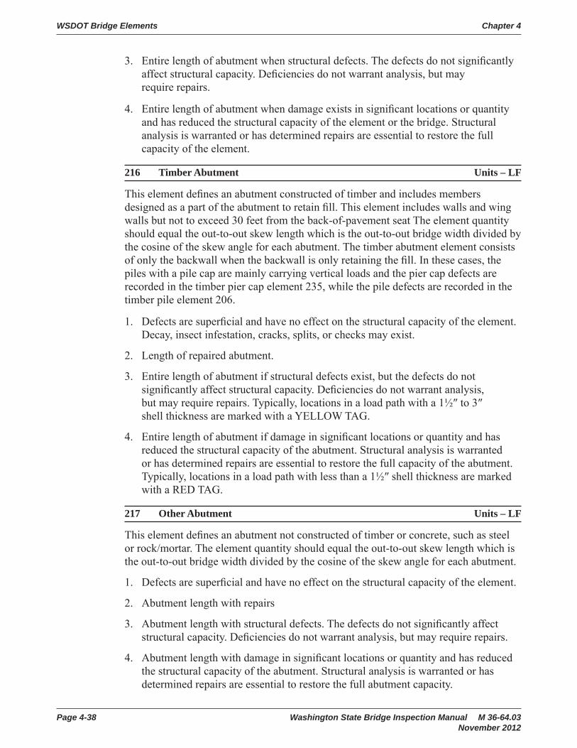
WSDOT Bridge Elements Chapter 4
Page 4-38 Washington State Bridge Inspection Manual M 36-64.03 November 2012
3. Entire length of abutment when structural defects. The defects do not signifi cantly affect structural capacity. Defi ciencies do not warrant analysis, but may require repairs.
4. Entire length of abutment when damage exists in signifi cant locations or quantity and has reduced the structural capacity of the element or the bridge. Structural analysis is warranted or has determined repairs are essential to restore the full capacity of the element.
216 Timber Abutment Units – LF
This element defi nes an abutment constructed of timber and includes members designed as a part of the abutment to retain fi ll. This element includes walls and wing walls but not to exceed 30 feet from the back-of-pavement seat The element quantity should equal the out-to-out skew length which is the out-to-out bridge width divided by the cosine of the skew angle for each abutment. The timber abutment element consists of only the backwall when the backwall is only retaining the fi ll. In these cases, the piles with a pile cap are mainly carrying vertical loads and the pier cap defects are recorded in the timber pier cap element 235, while the pile defects are recorded in the timber pile element 206.
1. Defects are superfi cial and have no effect on the structural capacity of the element. Decay, insect infestation, cracks, splits, or checks may exist.
2. Length of repaired abutment.
3. Entire length of abutment if structural defects exist, but the defects do not signifi cantly affect structural capacity. Defi ciencies do not warrant analysis, but may require repairs. Typically, locations in a load path with a 1½″ to 3″ shell thickness are marked with a YELLOW TAG.
4. Entire length of abutment if damage in signifi cant locations or quantity and has reduced the structural capacity of the abutment. Structural analysis is warranted or has determined repairs are essential to restore the full capacity of the abutment. Typically, locations in a load path with less than a 1½″ shell thickness are marked with a RED TAG.
217 Other Abutment Units – LF
This element defi nes an abutment not constructed of timber or concrete, such as steel or rock/mortar. The element quantity should equal the out-to-out skew length which is the out-to-out bridge width divided by the cosine of the skew angle for each abutment.
1. Defects are superfi cial and have no effect on the structural capacity of the element.
2. Abutment length with repairs
3. Abutment length with structural defects. The defects do not signifi cantly affect structural capacity. Defi ciencies do not warrant analysis, but may require repairs.
4. Abutment length with damage in signifi cant locations or quantity and has reduced the structural capacity of the abutment. Structural analysis is warranted or has determined repairs are essential to restore the full abutment capacity.

Chapter 4 WSDOT Bridge Elements
Washington State Bridge Inspection Manual M 36-64.03 Page 4-39November 2012
218 Steel Abutment Units – LF
This element defi nes an abutment constructed of structural steel.
1. Defects are superfi cial and have no effect on the structural capacity of the element.
2. Steel span length of abutment with repairs such as: bolts or rivets have been replaced; cracks that have been drilled or plated.
3. Steel span length of abutment with structural defects. The defects do not signifi cantly affect structural capacity. Defi ciencies do not warrant analysis, but may require repairs. Structural defi ciencies are not limited to impact damage, cracks, broken bolts, or measurable section loss due to corrosion (note the location and depth).
4. Steel span length of abutment affected by damage in signifi cant locations or quantity and has reduced the structural capacity of the element or the bridge. Structural analysis is warranted or has determined repairs are essential to restore the full capacity of the element.
219 Concrete Cantilevered Span Abutment Units – LF
This element defi nes an abutment for a bridge (bridge) span that is cantilevered from the fi rst or last pier. These bridges do not have a true abutment like other bridges. The “Cantilever Span Abutment” element was created to keep this abutment type separate from the typical abutment elements. The default notation assumes the pavement seat (abutment 1) is Pier 1; the cantilever span is Span 1; the fi rst pier is Pier 2.
1. Defects are superfi cial and have no effect on the structural capacity of the element. There may be discoloration, effl orescence, and/or superfi cial cracking, spalls, or delaminations.
2. Abutment length with repairs or patched.
3. Abutment length with structural defects. The defects do not signifi cantly affect structural capacity. Defi ciencies do not warrant analysis, but may require repairs.
4. Abutment length with damage in signifi cant locations or quantity and has reduced the structural capacity of the element or the bridge. Structural analysis is warranted or has determined repairs are essential to restore the full capacity of the element.
220 Concrete Submerged Foundation Units – EA
This element defi nes a reinforced concrete foundation footing supported by shafts, piles, or soil (spread footing) that is visible for inspection. The piles may be timber, concrete or steel. The foundation may be always or seasonally covered by water. Scour defi ciencies at a concrete abutment are included in element 361 and are not included in this element.
Elem 219
Cantilevered Span Abutment

WSDOT Bridge Elements Chapter 4
Page 4-40 Washington State Bridge Inspection Manual M 36-64.03 November 2012
221 Concrete Foundation Units – EA
This element defi nes a reinforced concrete foundation footing supported by shafts, piles, or soil (spread footing) that is visible for inspection. The piles may be timber, concrete or steel. Scour defi ciencies at a concrete foundation are included in element 361 and are not included in this element. Plinths are a form of spread footing and included in this element which are a small concrete base that supports a column.
1. Defects are superfi cial and have no effect on the structural capacity of the element. There may be discoloration, effl orescence, and/or superfi cial cracking, spalls, or delaminations.
2. Number of foundations with repairs.
3. Number of foundations with structural defects. The defects do not signifi cantly affect structural capacity. Defi ciencies do not warrant analysis, but may require repairs.
4. Number of foundations with damage in signifi cant locations or quantity and has reduced the structural capacity of the element or the bridge. Structural analysis is warranted or has determined repairs are essential to restore the full capacity of the element.
222 Timber Foundation Units – LF
This element defi nes a timber foundation element that includes a mud sill which is a spread footing and the rare case of a pile supported footing. A timber pile supported footing is a where timber horizontal footing member is a support for columns and the timber member is supported by piles.
1. Defects are superfi cial and have no effect on the structural capacity of the element. Decay, insect infestation, cracks, splits, or checks may exist.
2. Total length of foundation if repairs exist.
3. Total length of foundation if structural defects exist, but the defects do not signifi cantly affect structural capacity. Defi ciencies do not warrant analysis, but may require repairs. Typically, locations in a load path with a 1½″ to 3″ shell thickness are marked with a YELLOW TAG.
4. Total length of foundation where damage exists in signifi cant locations or quantity and has reduced the structural capacity of the element or the bridge. Structural analysis is warranted or has determined repairs are essential to restore the full capacity of the element. Typically, locations in a load path with less than a 1½ shell thickness are marked with a RED TAG.
225 Steel Submerged Pile/Column Units – EA
This element defi nes a column or column portion of a pile constructed of steel and is visible for inspection. The exposure may be intentional or caused by scour.

Chapter 4 WSDOT Bridge Elements
Washington State Bridge Inspection Manual M 36-64.03 Page 4-41November 2012
226 Prestressed Concrete Submerged Pile/Column Units – EA
This element defi nes a submerged column or column portion of a pile constructed of prestressed concrete and is visible for inspection. The exposure may be intentional or caused by scour.
227 Concrete Submerged Pile/Column Units – EA
This element defi nes a submerged column or column portion of a pile constructed of reinforced concrete and is visible for inspection. The exposure may be intentional or caused by scour.
1. Defects are superfi cial and have no effect on the structural capacity of the element. There may be discoloration, effl orescence, and/or superfi cial cracking, spalls, or delaminations.
2. Number of pile/columns with repairs.
3. Number of pile/columns with structural defects. The defects do not signifi cantly affect structural capacity. Defi ciencies do not warrant analysis, but may require repairs.
4. Number of pile/columns with damage in signifi cant locations or quantity and has reduced the structural capacity of the element or the bridge. Structural analysis is warranted or has determined repairs are essential to restore the full capacity of the element.
228 Timber Submerged Pile/Column Units – EA
This element defi nes a submerged column or column portion of a pile constructed of reinforced timber and is visible for inspection. The exposure may be intentional or caused by scour.
1. Defects are superfi cial and have no effect on the structural capacity of the element. Decay, insect infestation, cracks, splits, or checks may exist.
2. Number of pile/columns with repairs, plates, or splices.
3. Number of pile/columns with structural defects. The defects do not signifi cantly affect structural capacity. Defi ciencies do not warrant analysis, but may require repairs. Typically, locations in a load path with a 1½″ to 3″ shell thickness are marked with a YELLOW TAG.
4. Number of pile/columns with damage in signifi cant locations or quantity and has reduced the structural capacity of the element or the bridge. Structural analysis is warranted or has determined repairs are essential to restore the full capacity of the element. Typically, locations in a load path with less than a 1½″ shell thickness are marked with a RED TAG.

WSDOT Bridge Elements Chapter 4
Page 4-42 Washington State Bridge Inspection Manual M 36-64.03 November 2012
231 Steel Pier Cap/Crossbeam Units – LF
This element defi nes a steel pier cap or crossbeam.
1. Defects are superfi cial and have no effect on the structural capacity of the element.
2. Steel span length of pier cap/crossbeam with repairs.
3. Steel span length of pier cap/crossbeam with structural defects. The defects do not signifi cantly affect structural capacity. Defi ciencies do not warrant analysis, but may require repairs. Structural defi ciencies are not limited to impact damage, cracks, broken bolts, or measurable section loss due to corrosion (note the location and depth).
4. Steel span length of pier cap/crossbeam with damage in signifi cant locations or quantity and has reduced the structural capacity of the element or the bridge. Structural analysis is warranted or has determined repairs are essential to restore the full capacity of the element. Structural defi ciencies are not limited to impact damage, corrosion, a crack in primary load path member or in the attachment welded to primary member. Retain the quantity of the element reported in CS4 if the element is repainted but not repaired.
233 Prestressed Concrete Pier Cap/Crossbeam Units – LF
This element defi nes a prestressed concrete pier cap or crossbeam.

Chapter 4 WSDOT Bridge Elements
Washington State Bridge Inspection Manual M 36-64.03 Page 4-43November 2012
234 Concrete Pier Cap/Crossbeam Units – LF
This element defi nes a reinforced concrete pier cap or crossbeam. Integral pier caps with girders framed directly into the crossbeam are also included in this element.
1. Defects are superfi cial and have no effect on the structural capacity of the element. There may be discoloration, effl orescence, and/or superfi cial cracking, spalls, or delaminations.
2. Length of pier cap/crossbeam affected by repair or patch. Capacity repairs such as a strand splicing should record girder span length.
3. Length of pier cap/crossbeam affected by defects. The defects do not signifi cantly affect structural capacity. Defi ciencies do not warrant analysis, but may require repairs. Girder with defects such as: delaminations, spalls, structural cracking, exposed or corroded reinforcing or strands.
4. Length of pier cap/crossbeam affected by damage in signifi cant locations or quantity and has reduced the structural capacity of the element or the bridge. Structural analysis is warranted or has determined repairs are essential to restore the full capacity of the element.
235 Timber Pier Cap Units – LF
This element defi nes a timber pier cap that directly supports the superstructure.
1. Defects are superfi cial and have no effect on the structural capacity of the element. Decay, insect infestation, cracks, splits, or checks may exist.
2. Length of pier cap with repairs, plates, or splices.
3. Length of pier cap with structural defects. The defects do not signifi cantly affect structural capacity. Defi ciencies do not warrant analysis, but may require repairs. Typically, locations in a load path with a 1½″ to 3″ shell thickness are marked with a YELLOW TAG.
4. Length of pier cap with damage in signifi cant locations or quantity and has reduced the structural capacity of the element or the bridge. Structural analysis is warranted or has determined repairs are essential to restore the full capacity of the element. Typically, locations in a load path with less than a 1 ½ shell thickness are marked with a RED TAG.
WSDOT Bridge Elements Chapter 4
Page 4-44 Washington State Bridge Inspection Manual M 36-64.03 November 2012
236 Concrete Floating Pontoon Units – Cell
A concrete fl oating bridge is a series of post-tensioned fl oating pontoons which are subdivided into internal compartments called cells. Traffi c may ride directly on the top of the pontoon or the roadway may be elevated above the pontoon and supported by columns. This element includes all pontoons regardless of size or confi guration and all cells shall be evaluated at the same risk to the bridge condition. Deck elements will apply for the entire length of the pontoon structure. Pontoon condition will include the top slab where the deck /soffi t elements exist on the pontoon. The deck/soffi t elements are not included where the deck is elevated above the pontoon. The total quantity for the Concrete Floating Pontoon element is equal to the total number of pontoon cells for the bridge.
Concrete pontoons are specially designed to be water tight and dry while in service. The concrete is specifi cally designed to be visually crack free and have low permeability with water tight construction joints. Water tight design is the basis for condition evaluation of the pontoon below water line and is to include, but is not limited to the assessment of post-tensioned concrete, connections between pontoons, element 237-Pontoon hatch/bulkheads, and the risk to buoyancy. Water tight criteria shall not apply to the evaluations of conventionally designed concrete conditions above the waterline.
Concrete cracking shall be assessed on the location: Above or below the waterline; Whether it is in an exterior or interior wall; Whether it is active or in-active; And based on the design criteria that visible cracking should not exist on submerged surfaces.
An active crack is defi ned for this element as a crack that allows water to pass into or through a concrete section which is a risk for transporting fi ne materials out of the section or a source of contaminates into the section. Active cracks may be visible under normal bridge loading or only visible under storm conditions.
Seepage is defi ned as a cell with a water depth that is stable at less than 1 inch. Ballasted cells shall establish a void ratio of the ballast to calculate a volume of water in a cell.
This Concrete Floating Pontoon element also defi nes the relationship between the bridge element condition and the corresponding NBI Substructure Condition rating or FHWA Item 060.
1. Number of pontoon cells with defects that are superfi cial and are insignifi cant to structural capacity or buoyancy of the cell, pontoon or bridge. The cell is dry. A cell may have water present due to condensation caused when a deck hatch is opened.
• If the total quantity is in CS1, then FHWA Item 060 shall be an 8.
2. Number of pontoon cells with a repair such as, but not limited to a concrete patch or a sealed crack.
• If repairs are above water level, then FHWA Item 060 shall be a 7.
• If repairs below water level, then FHWA Item 060 shall be a 6.

Chapter 4 WSDOT Bridge Elements
Washington State Bridge Inspection Manual M 36-64.03 Page 4-45November 2012
• If 20 percent of the cells in one pontoon, or a total of 10 percent of the cells in adjoining pontoons, or 5 percent of the total element quantity are in CS2, then FHWA Item 060 shall be a 5.
3. Number of pontoon cells with signifi cant defects. Conventional concrete defects above the waterline which does not affect structural capacity of the concrete. Water tight defects below the waterline which may affect buoyancy of the cell, pontoon or the bridge. Typical CS3 submerged defects include, but are not limited to: Cracks that are stable or inactive for several storm events; Areas of concrete that are moist or have leachate present; Any cells that are consistently in a damp or “trace condition.”
• If cells are in CS3 due to seepage, then FHWA Item 060 shall be a 6.
• If eight or more adjacent or contiguous cells in a single pontoon are in CS3, then FHWA Item 060 shall be a 5.
• If 20 percent of the cells in one pontoon, or a total of 10 percent of the cells in adjoining pontoons or 5 percent of the total element quantity are in CS3, then FHWA Item 060 shall be a 4.
4. Number of pontoon cells with damage in signifi cant locations or quantity which has reduced the structural capacity of the pontoon or threatens the buoyancy of a cell, the pontoon or the bridge. Wet conditions that indicate a threat to a cell’s buoyancy include, but not limited to: Water leaks more than 1 inch per year in three consecutive years; Water leaks 2 inches or more in a year; Any cell visually leaking water. Any cell with a pontoon hatch or bulkhead in CS4, see element 237.
• If cells are in CS4, then FHWA Item 060 shall be a 4.
• If eight or more non-adjacent cells in a single pontoon are in CS4 or one cell leaks ½ inch per month, then FHWA Item 060 shall be a 3.
• If eight or more adjacent cells in a single pontoon are in CS4, or one cell leaks 1 inch of water per month, then FHWA Item 060 shall be a 2.
• If 20 percent of the cells in one pontoon, or a total of 10 percent of the cells in adjoining pontoons or 5 percent of the total element quantity are in CS4, then FHWA Item 060 shall be a 2.
• If one cell leaks 1 inch of water per month, for three consecutive months, then the FHWA Item 060 shall be a 1 and the bridge shall be closed to traffi c.
• If there is a measurable or visual change in the alignment or the free board distance at any location on the pontoon, then the FHWA Item 060 shall be a 1 and the bridge shall be closed to traffi c.

WSDOT Bridge Elements Chapter 4
Page 4-46 Washington State Bridge Inspection Manual M 36-64.03 November 2012
237 Pontoon Hatch/Bulkhead Units – EA
This element defi nes a steel deck or bulkhead hatch access. Deck hatches are accessed from the exterior of a pontoon and bulkhead hatches provide access between cells. The condition evaluation of a hatch includes, but is not limited to the ability of a hatch to provide a watertight structural seal. The performance of the hatches is critical to the design buoyancy of the pontoon structure during extreme events. The total element quantity should equal the total number of hatch and bulkheads on a bridge.
1. Defects are superfi cial and are insignifi cant to performance of the hatch. Insignifi cant amounts of water enter a cell when a deck hatch is opened.
2. Number of hatch/bulkheads with repairs such as: replaced seals, repaired hold-down dogs or locks.
3. Number of hatch/bulkheads with structural defects. The defects do not threaten performance of the hatch.
4. Number of hatch/bulkheads with damage that threatens performance during an extreme event. All pontoon cells in element 236 shall be coded CS4 that have a deck hatch or bulkhead hatch coded CS4.
238 Floating Bridge – Anchor Cable Units – EA
This element defi nes a steel anchor cable used in a fl oating bridge. The condition of a fl oating pontoon anchor cable is evaluated during underwater inspections performed by divers and remotely operated vehicles. Condition evaluation is based on cable protection system, breakage of wires within the cable and the condition of the cable anchor. The total element quantity should equal the number of fl oating pontoon anchor cables attached to the bridge.
1. Number of cables or anchors with no defects in the cable or anchor and the galvanized protection system is functioning properly. New replacement cables are coded in this condition state. (Corresponds to NBI substructure rating of 7 or 8.)
2. Number of cables or anchors with defects that are insignifi cant and do not affect the capacity of the cable. The galvanized protection system is showing signs of failure, and surface or freckled rust may exist with no signifi cant loss of section. If any portion of the cable or anchor is CS2, then the NBI Substructure Condition rating (FHWA Item 060) shall be a maximum of 6.
3. Number of cables or anchors with defects that are beginning to affect the capacity of the cable, but are within acceptable design limits. Corrosion section loss is present. Single wire failures of the cable may exist due to corrosion or hydrogen embrittlement, but no closer than 30 feet apart.

Chapter 4 WSDOT Bridge Elements
Washington State Bridge Inspection Manual M 36-64.03 Page 4-47November 2012
4. Number of cables or anchors with defects that have signifi cantly affected the capacity. Two or more broken wires, or equivalent section loss due to other defects, are within 30 feet. If any portion of the cable or anchor is CS4, then the NBI Substructure Condition rating (FHWA Item 060) shall be a maximum of 4. If two or more adjacent cables (on the same side or opposite sides of the pontoon) or more than four cables on the structure are CS4, then the NBI Substructure Condition rating (FHWA Item 060) shall be 3.
4.4 Culverts
240 Metal Culvert Units – LF
This element defi nes a metal (steel, aluminum, etc.) culvert including arches, round or elliptical pipes, etc.
1. Defects are superfi cial and have no effect on the structural capacity of the element. There may be corrosion, erosion, scour, distortion, or roadway settlement.
2. Length of culvert with repairs.
3. Length of culvert with structural defects. The defects do not signifi cantly affect structural capacity. Defi ciencies do not warrant analysis, but may require repairs.
4. Length of culvert affected by damage in signifi cant locations or quantity and has reduced the structural capacity of the culvert. Structural analysis is warranted or has determined repairs are essential to restore the full capacity of the element. Major deterioration, distortion, defl ection, roadway settlement, or misalignment of the barrel may be in visible.
241 Concrete Culvert Units – LF
This element defi nes all precast and cast-in-place (conventional or prestressed) concrete arch, pipe and box culverts.
1. Defects are superfi cial and have no effect on the structural capacity of the element. There may be discoloration, effl orescence, and/or superfi cial cracking, spalls, or delaminations.
2. Length of culvert with repair or patch.
3. Length of culvert affected by defects. The defects do not signifi cantly affect structural capacity. Defi ciencies do not warrant analysis, but may require repairs. Culvert with defects such as: delaminations, spalls, structural cracking, exposed or corroded reinforcing or strands.
4. Length of culvert affected by damage in signifi cant locations or quantity and has reduced the structural capacity of the element or the bridge. Structural analysis is warranted or has determined repairs are essential to restore the full capacity of the culvert. Major deterioration, distortion, defl ection, roadway settlement, or misalignment of the barrel may be in visible.
WSDOT Bridge Elements Chapter 4
Page 4-48 Washington State Bridge Inspection Manual M 36-64.03 November 2012
242 Timber Culvert Units – LF
This element defi nes all timber box culverts.
1. Defects are superfi cial and have no effect on the structural capacity of the element. Decay, insect infestation, cracks, splits, or checks may exist.
2. Length of culvert that has been replaced, repaired, patched, or plated.
3. Length of culvert with structural defects. The defects do not signifi cantly affect structural capacity. Defi ciencies do not warrant analysis, but may require repairs. Typically, locations in a load path with a 1½″ to 3″ shell thickness are marked with a YELLOW TAG.
4. Length of culvert affected by damage in signifi cant locations or quantity and has reduced the structural capacity of the element or the bridge. Structural analysis is warranted or has determined repairs are essential to restore the structural capacity of the culvert. Major deterioration, distortion, defl ection, roadway settlement, or misalignment of the barrel may be in visible. Typically, locations in a load path with less than a 1½″ shell thickness are marked with a RED TAG.
243 Other Culvert Units – LF
This element defi nes all culverts not included under steel, concrete, or timber culvert elements. It may include masonry or combinations of other materials.
1. Defects are superfi cial and have no effect on the structural capacity of the culvert.
2. Length of culvert with repairs.
3. Length of culvert with structural defects. The defects do not signifi cantly affect structural capacity. Defi ciencies do not warrant analysis, but may require repairs.
4. Length of culvert affected by damage in signifi cant locations or quantity and has reduced the structural capacity of the culvert. Structural analysis is warranted or has determined repairs are essential to restore the structural capacity of the culvert. Major deterioration, distortion, defl ection, roadway settlement, or misalignment of the barrel may be in visible.
4.5 Tunnels
250 Tunnel – Concrete Lined Units – SF
This is an element used to identify concrete lined tunnels. Use the CoRe elements to record the elements that exist inside the tunnel.
251 Tunnel – Timber Lined Units – SF
This is an element used to identify timber-lined tunnels. Use the CoRe elements to record the elements that exist inside the tunnel.

Chapter 4 WSDOT Bridge Elements
Washington State Bridge Inspection Manual M 36-64.03 Page 4-49November 2012
252 Tunnel – Unlined Units – SF
This is an element to identify unlined tunnels. Use the CoRe elements to record the elements that exist inside the tunnel.
1. Defects are superfi cial and have no effect on the structural capacity of the tunnel.
2. Tunnel area with repairs or patches.
3. Tunnel area with structural defects. The defects do not signifi cantly affect structural capacity. Defi ciencies do not warrant analysis, but may require repairs.
4. Tunnel area affected by damage in signifi cant locations or quantity and has reduced the structural capacity of the tunnel (or tunnel liner). Structural analysis is warranted or has determined repairs are essential to restore the full capacity of the element.
253 Tunnel Tile Units – SF
This is an element to identify tunnel tile.
1. Tile is bonded with no cracks, chips, or blemishes. Tile may be dirty but refl ectivity is enhanced during regular tunnel washing operations.
2. Tile area that has been repaired.
3. Tile area that is bonded, but cracked and may have effl orescence or small amounts of section loss. Tile may be blemished from impact or other causes resulting in major loss of refl ectivity.
4. Tile area with delaminations based on soundings, is completely missing, or has major section loss warranting replacement.
4.6 Sidewalk and SupportsA sidewalk is an element that provides pedestrian access across a bridge. A sidewalk is supported by a bridge deck and/or by sidewalk brackets that consist of several types of materials. The purpose of the sidewalk BMS is to record the structural integrity of the support system and sidewalk. Identify these elements in BMS if the sidewalk width is greater than or equal to 3 feet.
However, there are exceptions that must be accommodated. When there is a true sidewalk on a bridge as determined by the design, approach sidewalks, and location, it is appropriate to enter a sidewalk element in the BMS. Timber sidewalks, for example, may be narrow and have a support system. These exceptions should include a sidewalk BMS element. Please make a specifi c note explaining the reasoning for including the sidewalk element.

WSDOT Bridge Elements Chapter 4
Page 4-50 Washington State Bridge Inspection Manual M 36-64.03 November 2012
If a rail retrofi t or a wide curb has been determined to NOT be a sidewalk, then Bridge Rail elements will be used to document defects.
Elem 264 Elem 260 Elem 260
260 Steel Open Grid Sidewalk and Supports Units – SF
This element defi nes a sidewalk constructed of steel grids that are open and unfi lled. This element also includes the members used to provide support like stringers and braces. The total quantity should equal the width of the sidewalk times its length.
261 Steel Concrete Filled Grid Sidewalk and Supports Units – SF
This element defi nes a sidewalk constructed of steel grids that have been fi lled with concrete. This element also includes the members used to provide support like stringers and braces. The total quantity should equal the width of the sidewalk times its length.
262 Corrugated/Orthotropic Sidewalk and Supports Units – SF
This element defi nes a sidewalk constructed of corrugated metal fi lled with Portland cement concrete or asphaltic concrete or an orthotropic steel deck. This element also includes the members used to provide support like stringers and braces. The total quantity should equal the width of the sidewalk times its length.
264 Timber Sidewalk and Supports Units – SF
This element defi nes a sidewalk constructed of timber. This element also includes the members used to provide support like stringers and braces. The total quantity should equal the width of the sidewalk times its length.
SidewalkDeck
Traffic BarrierTraffic BarrierSidewalkDeck
Ped BarrierDeck
Sidewalk
Sidewalk Supports

Chapter 4 WSDOT Bridge Elements
Washington State Bridge Inspection Manual M 36-64.03 Page 4-51November 2012
266 Concrete Sidewalk and Supports Units – SF
This element defi nes a sidewalk constructed of reinforced concrete. The concrete sidewalk may be supported by the roadway deck, bracing, diaphragms, or sidewalk stringers. The total quantity should equal the width of the sidewalk times its length.
267 Fiber Reinforced Polymer (FRP) Sidewalk and Supports Units – SF
This element defi nes a sidewalk constructed of fi ber-reinforced polymer. This element also includes the members used to provide support like stringers and braces. The total quantity should equal the width of the sidewalk times its length.
1. Defects are superfi cial and have no effect on the structural capacity of the sidewalk or supports.
2. Sidewalk area (or support projected area) with repairs or patches
3. Sidewalk area (or support projected area) with structural defects. The defects do not signifi cantly affect structural capacity. Defi ciencies do not warrant analysis, but may require repairs.
4. Sidewalk area (or support projected area) affected by damage in signifi cant locations or quantity and has reduced the structural capacity of the sidewalk support. Structural analysis is warranted or has determined repairs are essential to restore the full capacity of the element.
4.7 BearingsWhen an in-span hinge separates two structures, the joint, bearing, and seismic restrainers at the hinge will be documented in the dependent (or supported) structure only.
310 Elastomeric Bearing Units – EA
This element defi nes a bridge bearing that is constructed primarily of elastomers, with or without fabric or metal reinforcement.

WSDOT Bridge Elements Chapter 4
Page 4-52 Washington State Bridge Inspection Manual M 36-64.03 November 2012
311 Moveable Bearing (Roller, Sliding, etc.) Units – EA
This element defi nes those bridge bearings that provide for both defl ection and longitudinal movement by means of roller, rocker or sliding mechanisms.
311 – Movable (roller, sliding, ect.) 311 – Movable (roller, sliding, ect.)
312 Concealed Bearing or Bearing System Units – EA
This element defi nes those bridge bearings and/or bearing seats that are not accessible with tools or equipment and therefore are not open for detailed inspection.
313 Fixed Bearing Units – EA
This element defi nes those bridge bearings that provide for rotation only.
313 – Fixed Bearing
313 – Fixed Bearing
314 Pot Bearing Units – EA
This element defi nes those high load bearings with a confi ned elastomer. The bearing may be fi xed against horizontal movement, guided to allow sliding in one direction, or fl oating to allow sliding in any direction.
314 – Pot Bearing

Chapter 4 WSDOT Bridge Elements
Washington State Bridge Inspection Manual M 36-64.03 Page 4-53November 2012
315 Disc Bearing Units – EA
This element defi nes a high load bearing with a hard plastic disc. The bearing may be fi xed against horizontal movement, guided to allow sliding in one direction, or fl oating to allow sliding in any direction.
316 Isolation Bearing Units – EA
This element defi nes a bearing that is laminated and is a sandwich of neoprene and steel plates. The bearing contains a lead core that is primarily used for seismic loads. The isolation bearing is used to protect structures against earthquake damage.
1. Defects are superfi cial and have no effect on the superstructure movements or safe transfer of load to the substructure. Shear deformation, displacement, or cracking of grout pad may be present. Top and bottom surfaces may not be parallel.
2. Number of bearings with a repair.
3. Number of bearings with structural defects. The defects are not detrimental to the superstructure or the safe transfer of load to the substructure. Defi ciencies do not warrant analysis, but may require repairs.
4. Number of bearings with defects that are detrimental to the superstructure or the safe transfer of load to the substructure. Loss of minimum bearing area may be imminent. Structural analysis is warranted or has determined bearing repairs are essential to restore the safe movement or transfer of load to the substructure.
321 Concrete Roadway Approach Slab Units – SF
This element defi nes a structural concrete slab supported at the bridge abutment and the roadway pavement. This element is essentially a concrete deck element that documents the surface conditions of the approach slab. The element quantity is the total area of both concrete approach slabs attached to the bridge. Do not include asphalt shoulder if present.
1. Defects are superfi cial. The slab surface do not have spalls/delaminations or previous repairs. The deck surfaces may have cracks or rock pockets. Wear and rutting may expose aggregate or reinforcing.
2. Slab area with repairs or patches. Do not include the rare case rutting fi lled with patching material.
3. Slab area with spalling.
4. If the results of delamination testing on the approach slab are available, record the delaminated area CS4.

WSDOT Bridge Elements Chapter 4
Page 4-54 Washington State Bridge Inspection Manual M 36-64.03 November 2012
322 Bridge Impact Units – EA
This fl ag documents an increase to the bridge live load, or impact, due to hammering or dynamic response of the bridge from trucks passing on to the bridge. Truck speed may be considered when slower speeds reduce the impact. Total quantity is based on the direction of trucks on to the bridge. Head to head traffi c has two and bridges with a single direction of traffi c will have one, such as ramps or main line divided structures (N&S or E&W). Code the approach roadway in the condition state that best indicates the severity of the problem. For the roadway where trucks are leaving the structure, defi ciencies can be described and repairs may be called out. However, approach roadway will not be quantifi ed.
1. The number of approach roadways that are smooth. Hammer or dynamic response to the structure is not signifi cant. There may be small bumps or minor raveling of the pavement in the approach roadway.
2. The number of approach roadways (not approach slab) that have been repaired or feather patched to correct an approach problem. If a paving project has removed the repairs, then the fl ag may be deleted.
3. The number of approach roadways that are rough, but the increase in live load to the structure is minor. Hammering impact is minor due to the wheels passing over surface discontinuities such as joints, cracks, or potholes. Dynamic response is minor due to a dip or rise in the approach roadway alignment.
4. The number of approach roadways that are causing signifi cant increase in live load to the structure. Hammering impact is signifi cant due to the wheels passing over surface discontinuities such as joints, cracks, or potholes. Dynamic response is signifi cant due to a dip or rise in the approach roadway alignment.
4.8 Bridge RailBridge rail BMS elements are to be entered for each type of rail. For example, if there is W-beam or Thrie beam guardrail mounted on the concrete bridge rail, then the length of each metal and concrete element should be entered. If the original concrete bridge rail has aluminum rail installed on top (with or without a rail retrofi t), enter that quantity into the appropriate BMS element as well. In the element notes, describe what type of metal bridge or pedestrian rail has been entered.
330 Metal Bridge Railing Units – LF
This element defi nes all types and shapes of metal bridge railing aluminum, metal beam, rolled shapes, etc. The quantity should equal the total length measured along each bridge rail.
331 Concrete Bridge Railing Units – LF
This element defi nes all types and shapes of reinforced concrete bridge railing. The quantity should equal the total length measured along each bridge rail.

Chapter 4 WSDOT Bridge Elements
Washington State Bridge Inspection Manual M 36-64.03 Page 4-55November 2012
332 Timber Bridge Railing Units – LF
This element defi nes all types and shapes of timber railing. All elements of this rail (except connectors) must be timber. The quantity should equal the total length measured along each bridge rail.
333 Other Bridge Railing Units – LF
This element defi nes all types and shapes of bridge railing except those defi ned as METAL, CONCRETE or TIMBER. This element will include cable rails, and combinations of materials. The quantity should equal the total length measured along each bridge rail.
1. Defects are superfi cial and have no effect on the structural capacity of the element.
2. Bridge rail length with a repair.
3. Bridge rail length with structural defects. The defects do not signifi cantly affect structural capacity. Defi ciencies do not warrant analysis, but may require repairs. Structural defi ciencies are not limited to impact damage, cracks, broken bolts, or measurable section loss due to corrosion (note the location and depth), decay, or spalling.
4. Bridge rail length with damage in signifi cant locations or quantity and has reduced the structural capacity of the rail. Structural analysis is warranted or has determined repairs are essential to restore the full capacity of the element.
4.9 Pedestrian RailA pedestrian rail will typically be on the outside of a sidewalk and protected from traffi c by a Bridge Rail.
340 Metal Pedestrian Rail Units – LF
This element defi nes all types and shapes of metal pedestrian bridge railing including steel (excluding weathering steel), aluminum, metal beam, rolled shapes, etc. The quantity should equal the total length measured along each pedestrian rail.
341 Concrete Pedestrian Rail Units – LF
This element defi nes all types and shapes of reinforced concrete pedestrian bridge railing. The quantity should equal the total length measured along each pedestrian rail.
342 Timber Pedestrian Rail Units – LF
This element defi nes all types and shapes of timber pedestrian bridge railing. All elements of this rail (except connectors) must be timber. The quantity should equal the total length measured along each pedestrian rail.

WSDOT Bridge Elements Chapter 4
Page 4-56 Washington State Bridge Inspection Manual M 36-64.03 November 2012
343 Other Pedestrian Rail Units – LF
This element defi nes all types and shapes of pedestrian bridge railing except those defi ned as METAL, CONCRETE or TIMBER. This element will include cable rails, and combinations of materials. The quantity should equal the total length measured along each pedestrian rail.
1. Defects are superfi cial and have no effect on the structural capacity of the element.
2. Pedestrian rail length with a repair.
3. Pedestrian rail length with structural defects. The defects do not signifi cantly affect structural capacity. Defi ciencies do not warrant analysis, but may require repairs. Structural defi ciencies are not limited to impact damage, cracks, broken bolts, or measurable section loss due to corrosion (note the location and depth), decay, or spalling.
4. Pedestrian rail length with damage in signifi cant locations or quantity and has reduced the structural capacity of the rail. Structural analysis is warranted or has determined repairs are essential to restore the full capacity of the element.
4.10 Smart Flags
355 Damaged Bolts or Rivets Units – EA
This smart fl ag is used to identify superstructure steel elements that have broken or missing bolts and/or rivets. Report one unit for each occurrence in the corresponding condition state.
1. Number of damaged, missing, or loose bolts or rivets in secondary member(s).
2. Number of damaged, missing, or loose bolts or rivets has been replaced.
3. Number of damaged, missing, or loose bolts or rivets in a primary member(s).
356 Steel Cracking Units – EA
This smart fl ag is used to identify superstructure steel elements with cracks. Report one unit for each occurrence (or crack) in the corresponding condition state. If fatigue damage exists, which may warrant analysis of the element or the serviceability of the element is uncertain, contact a BPO supervisor immediately.
1. Number of steel cracks, of any length, in a secondary member(s).
2. Number of steel cracks within a load path that have been repaired or arrested. The bridge may still be prone to fatigue.
3. Number of steel cracks within a load path that are not arrested and less than 1 inch. Any cracks (typically cope cracks) must be repaired according to BPO specifi ed procedures.

Chapter 4 WSDOT Bridge Elements
Washington State Bridge Inspection Manual M 36-64.03 Page 4-57November 2012
4. Number of steel cracks within a load path that are not arrested and 1 inch or greater in length. Any cracks (typically cope cracks) must be repaired according to BPO specifi ed procedures.
357 Pack Rust Units – EA
The primary purpose of this smart fl ag is to quantify steel connections where rust expansion is visually defl ecting steel plates and should be addressed when the bridge is painted. Structural impacts to rust pack overstressing are recorded in the steel elements. The total quantity is the number of existing pack rust locations identifi ed by the inspector.
1. Approximate number of locations where visible pack rust exists and is less than ¼ inch thick.
2. Number of locations where pack rust is more than ¼ inch thick.
360 Bridge Movement Units – EA
The primary purpose of this smart fl ag is to identify structural movement that is causing signifi cant distress to the bridge. Movements may be horizontal, vertical, or rotational. Evidence of movement should be documented (photo) in such a way that future measurements can determine if the structure is still moving or has stabilized.
1. The entire bridge appears to have stabilized due to repairs or recent history of measurements. Tilt meters, piezometer tubes, or monitoring system show no movement in the past two years.
2. Bridge elements are moving but do not cause a signifi cant problem for the bridge. Bearings may be approaching design limits. Substructure elements may be moving.
3. Bridge movement is at or beyond design limits. Investigation and repair analysis of the bridge is warranted.
361 Scour Units – EA
This smart fl ag is used to identify foundation scour for bridges crossing waterways as observed during inspections. Its primary purpose is to identify bridge piers or abutments that are subject to scour and to provide some measure of the magnitude of that scour.
1. Number of pier/abutment foundations where no Scour exists, or the scour has been repaired and is functioning as designed.
2. Number of pier/abutment foundations where scour is superfi cial and has no effect on the foundation structural capacity. No exposed spread footings. Minimum pile embedment is greater than 10’. The substructure code is not affected by scour. Monitor scour condition.

WSDOT Bridge Elements Chapter 4
Page 4-58 Washington State Bridge Inspection Manual M 36-64.03 November 2012
3. Number of pier/abutment foundations where scour exists. The scour does not signifi cantly affect the foundation structural capacity. Scour does not warrant analysis, but may require repairs. If left unchecked, could adversely impact the foundation structural capacity. Top of spread footings may be exposed. Minimum pile embedment is between 5’ and 10’. The NBI substructure code (676) of 4 (poor condition) would be appropriate if the scour had undermined the foundation to the point the load carrying capacity of the pier or abutment had been reduced, or it was potentially unstable. Reanalysis of the scour code may be warranted. Repairs to the bridge may be warranted.
4. Number of pier/abutment foundations with scour damage in signifi cant locations or quantity and has reduced the foundation structural capacity. Structural analysis is warranted or has determined repairs are essential to restore the full capacity of the pier. Undermining of spread footings or foundation material is occurring. Minimum pile embedment is less than 5’. NBI scour code should be coded 2 or less. If local failure of the foundation or substructure element were possible, NBI substructure code should be a 3 (serious condition). Directly comment that the substructure rating is based on the pile embedment length. Evaluate and comment on any riprap or other scour countermeasures that are in place. Make a recommendation to evaluate the pile for lateral stability. Document the scour condition thoroughly. Repairs to the bridge are necessary.
362 Impact Damage Units – EA
This is a smart fl ag used to identify damage caused by impact from traffi c or other causes such as fl ood debris. A maximum of 1 unit can be coded in each condition state.
1. Impact damage has occurred. None of the prestressed system is exposed. Repair, patching, or heat straightening is not required.
2. Impact damage has been repaired or patched. Any damage to a prestressed system has been repaired and patched. Steel elements have been repaired and painted.
3. Impact damage has occurred. Any prestressed system exposure is due to a traffi c impact, but is not impaired. Patching concrete or heat straightening of steel is needed.
4. Impact damage has occurred and strength of the member is impaired. Analysis is warranted to ascertain if the member can be repaired or needs to be replaced.
366 Undercrossing – Safety Inspection Units – EA
This is a smart fl ag for safety checks of Railroad and other non-vehicular undercrossings. No other core elements are needed.
1. Report the entire bridge in condition state one (EA).

Chapter 4 WSDOT Bridge Elements
Washington State Bridge Inspection Manual M 36-64.03 Page 4-59November 2012
367 Movable Bridge Units – EA
This is a smart fl ag to identify movable bridges. BMS elements will be used in addition to this smart fl ag.
1. A Movable bridge with elements that do not require repair (EA).
2. A Movable bridge with elements that require repair (EA).
368 Seismic Pier Crossbeam Bolster Units – EA
This element identifi es concrete piers with seismic structural improvements.
1. Number of piers with a crossbeam bolster.
369 Seismic Pier Infi ll Wall Units – EA
This element identifi es concrete piers with seismic structural improvements.
1. Number of piers with a seismic pier infi ll wall.
4.11 Seismic RestrainersEarthquake restrainers have been installed on WSDOT bridges since the 1980s. The typical longitudinal restrainer uses epoxy coated Dywidag bars with a designed gap maintained by double nuts. An earlier system using springs to maintain the required restrainer gap was used until the early 1990s when it was discontinued as being ineffective. Gap measurements are required during an inspection if visual inspection or loose double nuts indicate the gaps are not uniform.
370 Seismic – Longitudinal Restrainer Units – EA
This element is used to identify longitudinal seismic restrainers. When an in-span hinge separates two structures, the joint, bearing, and seismic restrainers at the hinge will be documented in the dependant (or supported) structure only. The quantity should equal the total number of longitudinal restrainers on the bridge.

WSDOT Bridge Elements Chapter 4
Page 4-60 Washington State Bridge Inspection Manual M 36-64.03 November 2012
371 Seismic – Transverse Restrainer Units – EA
This element is used to identify transverse seismic restrainers. When an in-span hinge separates two structures, the joint, bearing, and seismic restrainers at the hinge will be documented in the dependant (or supported) structure only. The quantity should equal the total number of transverse restrainers on the bridge.
372 Seismic – Link/Pin Restrainer Units – EA
This element is used to identify link/pin seismic restrainers. When an in-span hinge separates two structures, the joint, bearing, and seismic restrainers at the hinge will be documented in the dependant (or supported) structure only. The quantity should equal the total number of link/pin restrainers on the bridge.
1. Restrainer is in good condition and will function as designed. Anchor plate nuts have been checked and are in good condition.
2. Number of restrainers with misaligned seismic-longitudinal restrainer rods. Anchor plate nuts that are tight, but that have epoxy running down their bolts or are of varying lengths. The gap between adjacent longitudinal restrainers varies between ¼ inch and ¾ inch. Short transverse pipe restrainer length. Measure the depth of the diaphragm hole to the restrainer. Take a picture of the hole and tape measure.
3 Number of restrainers with improper anchor plate installation. Loose or inadequately bonded anchor nuts. A repair is warranted if over 25 percent of the anchor nuts have more than 2 inches of bolt thread exposed below the nut. Restrainer gap variation in a series of longitudinal seismic restrainers is greater than ¾ inches (measure and add the two gap distances on both sides of each restrainer in making your comparisons). Loose double nuts. Specify the replacement of the double nuts with (new) nuts having (with) setscrews and the resetting of the restrainer gaps according to the design tables. The inspector shall specify the required gaps, according to the bridge plans, in the repair.
373 Seismic – Catcher Block Units – EA
This element is used to identify a catcher block attached to a pier or abutment installed as part of a seismic retrofi t. The quantity should equal the total number of catcher blocks on the bridge.
1. Number of catcher blocks in good condition.
2. Number of catcher blocks with defi ciencies that need correction.

Chapter 4 WSDOT Bridge Elements
Washington State Bridge Inspection Manual M 36-64.03 Page 4-61November 2012
375 Cathodic Protection Units – EA
This is a smart fl ag used to identify a cathodic protection system used on a bridge. The quantity should equal the total number of cathodic protection systems on the bridge.
1. Code 1 if the cathodic protection system is functioning as designed.
2. Code 1 if the cathodic system is no longer functioning as designed.
376 Concrete Deck Delamination Testing Units – SF
This is a smart fl ag used to identify the results of concrete deck delamination testing. For Washington State bridges, the BMS engineer will provide the area of condition states and 376 notes for this element.
1. Deck area with no delaminations
2. For bridges with an ACP overlay, this is the area of concrete patching before an overlay was constructed. No action required by the inspector.
3. Deck area with concrete spalling measured in the Materials Lab Deck Delamination Test.
4. Deck area with concrete delamination measured in a Materials Lab Deck Delamination Test. This area should be recorded in the Concrete Deck CS4 (or Deck and Concrete Overlay CS4).
380 Unknown Pier Foundations Units – EA
This smart fl ag is used to identify the number of submerged unknown pier foundations on a bridge. The unknown status is based on nonexistent foundation plans for the pier. This is information only and no action is required of the inspector for this Smart Flag.
1. The number of submerged unknown pier foundations.

WSDOT Bridge Elements Chapter 4
Page 4-62 Washington State Bridge Inspection Manual M 36-64.03 November 2012
4.12 Expansion Joint BMSThe expansion joint condition states are designed to track the criteria associated with joint structural failure such as spalling, patches, and other structural problems. A spall within 1′-0″ of a joint system should be considered a joint spall and not included with the deck spalling. Spalls next to the joint are a joint defi ciency rather than deck deterioration.
Missing or defective joint glands are not considered structural joint failures in the joint condition states. Some joints are designed to pass water and many joints leak within days of installation. If the joint seal leakage is causing structural problems with elements below the joint, this should be noted in the report and a repair should be recommended. A smart fl ag or element may be used to track this deterioration in the future, but it is not included in the joint condition states at this time.
If any portion of a joint falls into a lower condition state, code the entire length of the joint in the lower condition state. Joints with structural defects are coded in CS2. Joints that require replacement are tracked in CS3. In general, joints in Condition State 3 will be programmed for rehabilitation or replacement.
When the entire joint is replaced with a new joint system, change the BMS element to the new joint type. Do not use more than one BMS element for a joint location, unless the structure has been widened and there are two joint systems present. Joint notes should reference specifi c joints by pier or span number.
When an in-span hinge separates two structures, the joint, bearing, and seismic restrainers at the hinge will be documented in the dependent (or supported) structure only.
400 Asphalt Butt Joint Seal Units – LF
This element defi nes a butt joint between concrete and asphalt pavement that is an asphalt sawcut fi lled with hot poured rubber. This element is shown in WSDOT Standard Plan A-40.20, Bridge Transverse Joint Seals for HMA. At the inspector’s discretion, this joint may also be applied at a butt joint at the end of the approach slab to extend the life of the asphalt. The quantity should equal the length measured along the joint.
1. The expansion joint is functioning as designed. Joint may not be perfect with signs of leakage. The adjacent concrete or asphalt is sound.
2. Skewed joint length at each location. “D” spalls or patches are present in the header or in the concrete within one foot of either side of the joint but no more than 10 percent of the length.
3. Skewed joint length at each location with the following typical criteria: When the concrete or asphalt must be rebuilt to maintain a reliable roadway surface; More than 10 percent of the joint length has spalls or patches adjacent to the seal; Asphalt was placed without a sawcut or the sawcut was not in the proper location.

Chapter 4 WSDOT Bridge Elements
Washington State Bridge Inspection Manual M 36-64.03 Page 4-63November 2012
401 Asphalt Open Joint Seal Units – LF
This element represents a sealed and sawcut contraction joint in asphalt bridge paving over an open concrete joint in a bridge deck or truss panel joint, as shown in WSDOT Standard Plan A-40.20, Bridge Transverse Joint Seals for HMA. The joint consists of hot poured rubber placed in an open concrete joint and a membrane may or may not exist. After the asphalt is placed, a sawcut is placed over the concrete joint and the gap fi lled with hot poured rubber. Elements 402 - Open Concrete Joint and 420 - Joint Paved Over fl ag do not apply at these locations. The quantity should equal the length measured along the joint.
Element 420 - the Joint Paved Over fl ag does apply for all locations of a buried steel joint due to the risk of planing equipment damaging the bridge deck.
1. The expansion joint is functioning as designed. Joint may not be perfect with signs of leakage. The adjacent concrete or asphalt is sound.
2. Skewed joint length at each location. “D” spalls or patches are present in the header or in the concrete within one foot of either side of the joint but no more than 10 percent of the length.
3. Skewed joint length at each location with the following typical criteria: When the concrete or asphalt must be rebuilt to maintain a reliable roadway surface; More than 10 percent of the joint length has spalls or patches adjacent to the seal; Asphalt was placed without a sawcut or the sawcut was not in the proper location.
402 Open Concrete Joint Units – LF
This element defi nes a joint designed to have concrete edges at the joint opening in a concrete wearing surface. The original design is usually fi lled with hot poured rubber or pre-molded joint fi ller and the design materials may or may not be present. This joint is typical for panel joints at a truss fl oorbeam and interior joints on older bridges. The quantity should equal the length measured along the expansion joint.
This is not to be confused with: Element 403 - Concrete Bulb-T joint, Elements 405 to 406 Compression Seals with the seal missing, or Element 417 - Rapid Cure Silicone (RCS) joint.
1. The expansion joint is functioning as designed. Joint may not be perfect with signs of leakage. The adjacent deck or header is sound.
2. Skewed joint length at each location with “D” spalls or patches are present in the header or in the deck within one foot of either side of the joint.
3. Skewed joint length at each location where the deck or headers must be rebuilt to maintain a reliable roadway surface. As a guideline, more than 25 percent of the joint length has spalls or patches in the deck or headers adjacent to the seal.
A repair to reseal the joints is required for bridges at each steel fl oorbeam where water is corroding the top fl ange and/or connections.

WSDOT Bridge Elements Chapter 4
Page 4-64 Washington State Bridge Inspection Manual M 36-64.03 November 2012
403 Concrete Bulb-T Units – LF
This element defi nes a joint formed to accept a Bulb-T preformed seal. The seal may be missing or other materials present to provide a seal. The quantity should equal the length measured along the expansion joint.
404 Compression Seal/Concrete Header Units – LF
This element defi nes a joint with concrete headers formed during the original construction of the bridge. The joint is fi lled with a pre-formed compression type seal. The quantity should equal the length measured along the expansion joint.
405 Compression Seal/Polymer Header Units – LF
This element defi nes those joints that have been rehabilitated with a polymer header and fi lled with a pre-formed compression type seal. The quantity should equal the length measured along the expansion joint.

Chapter 4 WSDOT Bridge Elements
Washington State Bridge Inspection Manual M 36-64.03 Page 4-65November 2012
406 Compression Seal/Steel Header Units – LF
This element defi nes a joint with steel angle plate headers that have a pre-formed compression type seal. The quantity should equal the length measured along the expansion joint.
407 Steel Angle Header Units – LF
This element defi nes an open joint with steel angle plate headers. The quantity should equal the length measured along the expansion joint.
408 Steel Sliding Plate Units – LF
This element defi nes a joint with steel sliding plates. The quantity should equal the length measured along the expansion joint.

WSDOT Bridge Elements Chapter 4
Page 4-66 Washington State Bridge Inspection Manual M 36-64.03 November 2012
409 Steel Sliding Plate w/Raised Bars Units – LF
This element defi nes a joint with steel sliding plates and steel raised bars welded to the plates to accommodate an overlay. The quantity should equal the length measured along the expansion joint.
410 Steel Fingers Units – LF
This element defi nes a joint with open steel fi ngers. The quantity should equal the length measured along the expansion joint.
411 Steel Fingers w/Raised Bars Units – LF
This element defi nes a joint with bars or plates welded to the steel fi nger plates to accommodate an overlay. The quantity should equal the length measured along the expansion joint.

Chapter 4 WSDOT Bridge Elements
Washington State Bridge Inspection Manual M 36-64.03 Page 4-67November 2012
412 Strip Seal – Anchored Units – LF
This element defi nes an expansion joint that uses a neoprene type waterproof gland with steel extrusion or other system to anchor the gland. The steel extrusion is anchored into the concrete deck or header. The quantity should equal the length measured along the expansion joint.
413 Strip Seal – Welded Units – LF
This element defi nes an expansion joint that uses a neoprene type waterproof gland with steel extrusion or other system to anchor the gland. The steel extrusion is welded to a pre existing steel expansion joint. The quantity should equal the length measured along the expansion joint.
414 Bolt Down – Sliding Plate w/springs Units – LF
This element defi nes a bolted sliding plate expansion joint that uses steel springs. The quantity should equal the length measured along the expansion joint.
1. The expansion joint is functioning as designed. Joint may not be perfect with signs of leakage. The adjacent deck or header is sound.
2. Skewed joint length at each location with “D” spalls or patches present in the header or in the deck within one foot either side of the joint.
3. Skewed joint length at each location where the deck or headers must be rebuilt to maintain a reliable roadway surface or to maintain seal placement. As a guideline, more than 25 percent of the joint length has spalls or patches in the deck or headers adjacent to the seal.

WSDOT Bridge Elements Chapter 4
Page 4-68 Washington State Bridge Inspection Manual M 36-64.03 November 2012
Steel Materials: Steel components are banging, cracked, loose, broken, or missing. Steel sections that have been removed and/or replaced with something else (usually concrete patching) should be CS3.
SpringBolt Down Sliding Plate
415 Bolt Down Panel – Molded Rubber Units – LF
This element defi nes an expansion joint that uses a waterproof gland that is held in place by molded rubber panels that are attached with bolts. The quantity should equal the length measured along the expansion joint.
1. The expansion joint is functioning as designed. Joint may not be perfect with signs of leakage. The adjacent deck or header is sound. Molded Rubber panels are secure and have no defects.
2. Skewed joint length at each location with “D” spalls or patches present in the header or in the deck within one foot either side of the joint. Some of the bolts may be broken but they represent less than 10 percent of the total for that panel.
3. Skewed joint length at each location where more than 10 percent of the bolts in a panel are missing, loose, or broken. As a guideline, more than 25 percent of the joint length has spalls or patches in the deck or headers adjacent to the seal

Chapter 4 WSDOT Bridge Elements
Washington State Bridge Inspection Manual M 36-64.03 Page 4-69November 2012
416 Assembly Joint Seal (Modular) Units – LF
This element defi nes a large movement joint that has an assembly mechanism with multiple neoprene type waterproof glands. The quantity should equal the length measured along the expansion joint.
417 Silicone Rubber Joint Filler Units – LF
This element defi nes an expansion joint that has been repaired with a single or two component rubber joint fi ller. The quantity should equal the length measured along the expansion joint.
1. The expansion joint is functioning as designed. Joint may not be perfect with signs of leakage. The adjacent deck or header is sound.
2. Skewed joint length at each location with “D” spalls or patches present in the header or in the deck within one foot either side of the joint.
3. Skewed joint length at each location where the deck or headers must be rebuilt to maintain a reliable roadway surface or to maintain seal placement. As a guideline, more than 25 percent of the joint length has spalls or patches in the deck or headers adjacent to the seal.
Steel Materials: Steel components are banging, cracked, loose, broken, or missing. Steel sections that have been removed and/or replaced with something else (usually concrete patching) should be CS3.

WSDOT Bridge Elements Chapter 4
Page 4-70 Washington State Bridge Inspection Manual M 36-64.03 November 2012
418 Asphalt Plug Units – LF
This element defi nes an expansion joint that has been replaced with an asphalt plug system. The quantity should equal the length measured along the expansion joint.
1. The expansion joint is functioning as designed. Joint may not be perfect with signs of leakage. The adjacent deck or header is sound.
2. Skewed joint length at each location with rutting in the joint is minor. “D” spalls or patches are present in the joint, or in deck adjacent to joint.
3. Skewed joint length at each location where the asphalt material in the joint has signifi cant rutting, bulging or is missing. As a guideline, more than 25 percent of the joint length has spalls or patches in the deck or headers adjacent to the seal.
–
419 Steel Angle w/Raised Bars Units – LF
This element defi nes a joint with steel angles and steel raised bars welded to the angles to accommodate an overlay. The quantity should equal the length measured along the expansion joint.
1. The expansion joint is functioning as designed. Joint may not be perfect with signs of leakage. The adjacent deck or header is sound.
2. Skewed joint length at each location with “D” spalls or patches present in the header or in the deck within one foot either side of the joint.
3. Skewed joint length at each location where the deck or headers must be rebuilt to maintain a reliable roadway surface or to maintain seal placement. As a guideline, more than 25 percent of the joint length has spalls or patches in the deck or headers adjacent to the seal.

Chapter 4 WSDOT Bridge Elements
Washington State Bridge Inspection Manual M 36-64.03 Page 4-71November 2012
Steel Materials: Steel components are banging, cracked, loose, broken, or missing. Steel sections that have been removed and/or replaced with something else (usually concrete patching) should be CS3.
420 Joint Paved Over Flag Units – LF
This element identifi es when a steel joint system that has been paved over with asphalt. This is a high risk to damaging the steel joint or bridge deck by the paving operations. When this fl ag is used, a cost for joint work will be included in the next paving contract to correct the problem. Since the joint cannot be inspected, the joint element condition states should remain unchanged (and so noted). Some steel joints may have more than 2.5” of asphalt may not require rehabilitation. The Total quantity will be the sum total length of all joint systems on the bridge.
1. Skewed joint length at each location that is paved over, but rehabilitation is not required.
2. Skewed joint length at each location that requires rehabilitation. A photo is helpful to determine the type of rehabilitation.
4.13 Movable Bridges
501 Movable Bridge Steel Tower Units – LF
This element defi nes the structural steel columns and members used to support a counter weight of a vertical lift span. The total quantity is the total of the supporting column lengths.
1. Defects are superfi cial and have no effect on the structural capacity of the element.
2. Tower column length with repairs such as: bolts or rivets have been replaced; cracks that have been drilled or plated.
3. Tower column length with structural defects. The defects do not signifi cantly affect structural capacity. Defi ciencies do not warrant analysis, but may require repairs.

WSDOT Bridge Elements Chapter 4
Page 4-72 Washington State Bridge Inspection Manual M 36-64.03 November 2012
4. Tower column length affected by damage in signifi cant locations or quantity and has reduced the structural capacity of the column or the tower. Structural analysis is warranted or has determined repairs are essential to restore the full capacity of the element. Structural defi ciencies are not limited to impact damage, corrosion, a crack in primary load path member or in the attachment welded to primary member. Retain the quantity of the element reported in CS4 if the element is repainted but not repaired.
4.14 Other Bridge Elements
705 Bridge Luminaire Pole and Base Units – EA
This element is defi ned by a light pole and anchor system attached to a bridge. It does not include the mast arm or other types of lights that may be attached to the bridge. The condition states describe the structural condition of the pole, anchor bolts, and support. Region maintenance may need to be contacted prior to inspection in order to remove bolt covers or otherwise provide access for inspection. The total element quantity should equal the number of luminaire poles attached to the bridge.
1. There are no signifi cant structural defects in the pole or support, and the grout pad is solid. Poles or supports that have been replaced are coded in this condition state.
2. Number of poles where structural inspection requires special equipment to access.
3. Number of poles with structural defects. The defects do not signifi cantly affect the structural capacity.
4. Number of poles affected by damage in signifi cant locations or quantity and has reduced structural capacity. Structural analysis is warranted or has determined repairs are essential to restore the full capacity of the element. Visual inspection indicates a base plate that is not supported by leveling nuts.
WSDOT categorizes overlays in to two different types. The fi rst type, ACP and Thin Overlay, is a deck protection system intended to prolong the life of the deck and wearing surface. The second type, Concrete Overlay, is intended to rehabilitate the deck and provide a new deck wearing surface.
ACP Overlays (BMS 800) can generally be identifi ed in the fi eld; the membrane below it cannot (BMS 801). Thin overlays may be identifi ed in the fi eld if the system has failed and chunks are missing. Deterioration of the ACP and thin overlays is not generally associated with the deterioration of the deck. The ACP may be replaced several times without exposing the concrete deck. Therefore, the condition states for the deck and overlay elements are independent and DIFFERENT. Spalls and delaminations are repaired (patched) on WSDOT bridges before placing the overlay. If the area of patching is known, this should be noted and recorded in the Deck element as CS2. If a new BST has been applied to an ACP surface, then the overlay element CS2 and CS3 are equal to zero.

Chapter 4 WSDOT Bridge Elements
Washington State Bridge Inspection Manual M 36-64.03 Page 4-73November 2012
800 Asphalt Concrete (AC) Overlay Units – SF
This element defi nes an Asphalt Concrete (AC) bridge deck overlay, with or without a Bituminous Surface Treatment (BST). The quantity should equal the overlay’s width times the length.
801 Asphalt Concrete (AC) Overlay With Waterproofi ng Membrane Units – SF
This element defi nes an asphaltic concrete with waterproofi ng membrane bridge deck overlay. The quantity should equal the overlay’s width times the length.
802 Thin Polymer Overlay Units – SF
This defi nes a thin polymer bridge deck overlay that is less than or equal to 0.5 inches in thickness (i.e., epoxy, methyl-methacrylate). The quantity should equal the overlay’s width times the length.
1. Defects are superfi cial. The deck surfaces have no spalls/delaminations or previous repairs. The deck surfaces may have cracking.
2. Total area of overlay patches.
3. Total area of overlay spalls or potholes. Thin Polymer Overlays (802) may have visible delaminations and should be considered as spalls and coded in CS3.
Concrete Overlay elements are diffi cult to discern in the fi eld and are identifi ed in special provisions or Plans. When constructing modifi ed concrete overlays, the material removed by the deck preparation (spalls and delams) is replaced with the overlay material. WSDOT considers this construction deck rehabilitation; or in other words, the concrete overlay and deck are monolithic. Therefore, CS2 and CS3 for the deck and concrete overlay will be the SAME. All defects noted in the concrete overlay (SF) apply to the deck. It is not uncommon to have the overlay break up when there is a problem in the deck below it.
803 Modifi ed Concrete Overlay Units – SF
This defi nes a rigid modifi ed concrete bridge deck overlay that is normally 1.5 inches or greater in thickness (i.e., Latex (LMC), Microsilica (MMC), Fly Ash (FMC)). The quantity should equal the overlay’s width times the length.
804 Polyester Concrete Overlay Units – SF
This defi nes a rigid polyester concrete bridge deck overlay that is normally 0.75 inches in thickness. The quantity should equal the overlay’s width times the length.
1. Defects are superfi cial. The deck surfaces have no spalls/delaminations or previous repairs. The deck surfaces may have hairline cracks or rock pockets.
2. Concrete overlay area with repairs or patches. Do not include the rare cases of rutting that has been fi lled with patching material.

WSDOT Bridge Elements Chapter 4
Page 4-74 Washington State Bridge Inspection Manual M 36-64.03 November 2012
3. Concrete overlay area with spalling.
4. If the results of deck delamination testing are available from Element 376, include the delaminated area in this CS4.
4.15 Bridge Deck Overlays
805 AC Over a Polymer Overlay Units – SF
This defi nes an asphaltic concrete applied over a thin polymer bridge deck overlay (i.e., epoxy, methyl-methacyrlate). The quantity should equal the overlay’s width times the length.
1. Defects are superfi cial. The deck surfaces have no spalls/delaminations or previous repairs. The deck surfaces may have cracking.
2. ACP overlay area with patches.
3. ACP overlay area with spalls or potholes.
806 BST on Concrete (Chip Seal) Units – SF
This defi nes a Bituminous Surface Treatment (BST), or commonly known as a chip seal, mistakenly applied directly on a concrete deck. This severely limits the inspection of the deck. Code the area of BST covering the concrete deck in CS1.
4.16 Protective CoatingsWSDOT inspectors must not change paint elements for state bridges. Inspectors will be notifi ed with a sticky note if the bridge has been repainted.
Steel Paint Area
The steel paint area is equal to the surface area of the steel members in the bridge. An estimate of the steel paint area may be made if bridge plans are not available but the steel tonnage is known. The following table provides an approximate conversion factor:
Bridge Type Square Feet Per Ton
Rolled or Plate Girder 110
Truss 160
901 Red Lead Alkyd Paint System Units – SF
This paint protection system is a 3-coat alkyd system incorporating lead based paint. Use this paint element as a default if the paint was installed prior to 1991.

Chapter 4 WSDOT Bridge Elements
Washington State Bridge Inspection Manual M 36-64.03 Page 4-75November 2012
902 Inorganic Zinc/Vinyl Paint System Units – SF
This paint protection system consists of an inorganic zinc silicate shop applied primer system and a vinyl is paint applied after erection, cleaning, and spot priming.
903 Inorganic Zinc/Urethane Paint System Units – SF
This paint protection system consists of a inorganic zinc silicate shop applied primer system and an epoxy, aliphatic urethane paint system applied after erection, cleaning, and spot priming. This paint system is used on new WSDOT steel bridges.
904 Organic Zinc/Urethane Paint System Units – SF
This paint protection system is a 3-coat system incorporating an organic zinc primer, an epoxy second coat and a moisture cured urethane topcoat. Use this paint element as a default if the paint was installed after 1991.
905 Coal Tar Epoxy Paint System Units – SF
This paint protection system incorporates a coal tar epoxy based product.
1. The paint system is sound and functioning as intended to protect the metal surface.
2. Paint system area with chalking, peeling, curling or showing other early evidence of paint system distress, but there is no exposure of metal.
3. Paint system area that is no longer effective. The metal substrate is exposed.
906 Metalizing Units – SF
This protection system consists of a sprayed coating of zinc or zinc/aluminum.
907 Galvanizing Units – SF
This protection system consists of zinc applied to steel in a variety of spray-on methods.
908 Epoxy Paint for Weathering Steel Units – SF
This protection system consists of a clear epoxy coating applied to weathering steel to prevent excessive corrosion.
1. Protection system area that is sound and functioning as intended to protect the metal surface.
2. Protection system area with corrosion of the substrate metal.

WSDOT Bridge Elements Chapter 4
Page 4-76 Washington State Bridge Inspection Manual M 36-64.03 November 2012
909 Zinc Primer Units – SF
This paint protection system consists of a zinc silicate shop applied primer system.
1. The paint system is sound and functioning as intended to protect the metal surface.
2. Protection system area with chalking, peeling, curling or showing other early evidence of paint system distress, but there is no exposure of metal.
3. Protection system area that is no longer effective. The metal substrate is exposed.
910 Weathering Steel Patina Units – SF
This protection system consists of a chemical compound formed on the surface of weathering steel elements and is called the patina. When exposed to the atmosphere, weathering steel develops a patina, which seals and protects the steel from further corrosion. This oxide fi lm is actually an intended layer of surface rust, which protects the member from further corrosion and loss of material thickness. The patina acts like a paint system to protect the steel. The color is an indicator of the condition of the patina may vary from orange to dark brown or purple-brown.
1. Weathering steel color is yellow orange to light brown. Some areas may not have rust. Patina has a dusty to granular texture.
2 Weathering steel area that is chocolate brown or purple brown in color (boldly exposed) and in good condition. The patina is tightly adhered, capable of withstanding hammering or vigorous wire brushing. The patina system is sound and functioning to protect the metal surface.
3. Weathering steel area that is black in color indicating non-protective patina. Area that remains damp for long periods of time due to rain, condensation, leaky joints, traffi c spray or other source of moisture. Area where debris has accumulated on a horizontal surface and the steel is continuously wet. Area with a texture of large granules (greater than ⅛″ diameter); fl aking (greater than ¼″ diameter) or laminar rusting in thin sheets.

Washington State Bridge Inspection Manual M 36-64.03 Page 5-1 November 2012
Chapter 5 Load Rating and Scour
5.01 GeneralThe National Bridge Inspection Standards (NBIS) requires a load rating be calculated for each bridge as well as a scour evaluation for any structure over water.
The load rating calculations and scour evaluations are a permanent part of the bridge file and are to be updated when the condition of the bridge changes. All load rating calculations shall be stamped, signed, and dated by a registered professional engineer.
5.02 Bridge Load RatingLoad rating of bridges shall be completed per Chapter 13 of the Bridge Design Manual M 23-50 and the AASHTO Manual for Bridge Evaluation (MBE). See the appendix in the MBE for examples of load rating different types of structures.
A. General Load Rating and Re-Rating Guidelines• The Load rating of new bridges shall be completed within 90 days of opening the
structure to the traveling public in the anticipated final configuration.
• The ratings of existing bridges shall be re-examined when the “Revise Rating Flag” is turned on. The condition of identified bridge elements shall be reviewed and the load ratings shall be updated if needed. In cases where the capacity of a member is reduced significantly, such as impact damage to a girder with loss of reinforcing or damage to steel members, ratings shall be updated within 30 days. In other cases such as increase in dead load, a preliminary assessment can be made based on the increase in dead load, condition of the structure and existing ratings. If in the engineer’s judgment, the ratings will not be affected significantly, and will not require a need to post or lower the load restriction on the bridge, ratings should be updated within 12 months.
B. Bridge Load Rating Revision Criteria
WSBIS element WB76, Item 88, Revise Rating should be coded as “Y” when one or more of the following items apply:
1. The Superstructure or Cross-beams/ Floor-beams Elements’ State condition changes from either Condition State 1 or State 2 to Condition State 3 or State 4.
2. The approach condition to the structure causes severe impact to the bridge. An option is to call for a high priority repair to fix the approaches so the transition onto the structure is smooth.
3. The deck has potholes on the surface or at the joints. An option is to call for a high priority repair to patch the potholes in the deck at the joints.

Load Rating and Scour Chapter 5
Page 5-2 Washington State Bridge Inspection Manual M 36-64.03 November 2012
4. The thickness of the overlay has increased.
5. The railing is replaced with a heavier traffic barrier.
6. New utilities such as water main or sewer line have been installed on the structure.
7. The number of striped lanes has increased on 2 line superstructure members such as trusses or 2-line girder bridge, and box girder bridges.
When a deficiency is observed in the field such as rot pockets in timber or section loss in a steel member, the inspector should provide the following items to assist in providing accurate rating factors:
1. The description “shell thickness” shall state whether the thickness is all around the member or on one side and whether it is full depth and location.
2. Section loss in steel members should include, if possible, the remaining section thickness, location of the section loss and length.
Provide a sketch of the deficient member and show deterioration as stated above and provide length of the deteriorated area. It is of great importance to provide as accurate information as possible instead of estimates. Posting or restricting a bridge is greatly dependent on this information.
C. Bridges With Unknown Structural Components
For concrete and masonry bridges with no design plans, and when the necessary reinforcing details are unknown and cannot be measured, load capacity ratings may be determined based on field inspection by a qualified bridge inspector followed by evaluation by a qualified engineer. Such a bridge does not need to be posted for load restrictions if it has been carrying normal traffic for an appreciable period of time and shows no sign of distress; Reference the manual for bridge Evaluation (MBE) second edition, Sections 6.1.4 and 6A.8.1. General rating guidelines for these structures are:
• Inventory rating shall be equal to the design truck at the time the bridge was constructed. Operating rating shall be equal to the inventory rating multiplied by 1.667.
• Legal trucks rating factors shall be equal to 1 when the Superstructure or Substructure NBI code is equal or greater than 5. Restriction of permit loads shall be assessed.
• Posting or restricting of a bridge shall be assessed when NBI condition rating of the superstructure or substructure is 4 or less or when there are signs of structural distress.
The Load Rating Methods WB75-51 and WB75-54 shall be coded as “A”, Administrative.
Full documentation for an administrative rating shall be placed in the bridge file.

Chapter 5 Load Rating and Scour
Washington State Bridge Inspection Manual M 36-64.03 Page 5-3 November 2012
D. Data Management
The WSBIS database shall be updated within 30 days from the completion and approval of a load rating of a structure.
E. Posting Requirements
Posting of a structure shall occur when the Operating rating factor for any of the legal loads is less than 1 based on the Load Factor or Allowable Stress Methods or the rating factor for any of the legal loads is less than 1 based on the Load and Resistance Factor Method.
Agencies generally post a bridge between the Inventory Rating and the Operating Rating using the Load Factor Method and Allowable Stress Methods. The minimum permissible posting value is three tons at inventory or operating levels. Bridges not capable of carrying a minimum gross live load of three tons shall be closed. The posted tonnage shall be the smaller of the rating factor for the specific truck times its weight or the gross vehicle weight of the truck.
In general, posting of a structure, when warranted, shall occur within 60 days from the date of the letter sent to the region or the date the local agency is notified by the engineer. In instances where the load carrying capacity of a bridge is significantly reduced, such as by impact to the structure, posting or closing of the bridge shall occur as soon as it is determined it is not safe to carry legal vehicular loads.
F. Overload Permits
Overweight loads traveling over state or local agency roads are required to obtain permits/approval from the state, county, or city maintaining those roadways. No permit loads shall be allowed over posted bridges. The first step in evaluating a permit is to determine if the configuration meets RCW 46.44 for maximum gross weight, load per axle, or axle group. The second step is to evaluate the structures on the traveled route. This can be accomplished in two methods.
The first method, which is more precise for a specific structure, is to model the permit load moving on the bridge and calculating its load rating factor. A single lane distribution factor can be used in the model, which means that no other trucks are permitted in the adjacent lanes. A rating factor equal to or above 1 means the permit truck can safely travel over the particular structure. Permit loads that have unusual configuration or have more than 8 tires per axles shall be evaluated using this method.
The second method is more general and the engineer shall be extremely cautious when applying it to ensure that the permit load is enveloped by one of the typical rated trucks. The method calculates the maximum weight per axle allowed over a bridge and is dependent on the load rating factors for the particular structure, as follows:

Load Rating and Scour Chapter 5
Page 5-4 Washington State Bridge Inspection Manual M 36-64.03 November 2012
• Truck Type SA
Definition: Construction Equipment Tires (a.k.a., Super Single Axle) (RCW 46.44.091(3))
Range: Up to 45,000 lbs. per axle.
Criteria: Using the Load Rating Factor for the AASHTO2 Truck (a.k.a., Type 3S2), which has a dual axle weighing 31,000 lbs., the equation is 45,000 lbs. * Rating Factor * 31/45 rounded to the nearest 500 lbs.
• Collection Truck (RCW 46.44.041) Restriction List
Truck Type S/A
Definition: Two-axle trucks where the rear drive axle is the item in question on non-interstate routes only.
Range: Up to 26,000 lbs. on rear axle.
Criteria: Using the Load Rating Factor for the AASHTO1 Truck (a.k.a., Type 3), which has a dual axle weighing 34,000 lbs., the equation is 26,000 lbs. * Rating Factor * 26/34 rounded to the nearest 500 lbs.
• Truck Type T/D
Definition: Three-axle trucks where the rear tandem drive axles are the item in question on non-interstate routes only.
Range: Up to 42,000 lbs. on rear dual.
Criteria: Using the Load Rating Factor for the AASHTO1 Truck (a.k.a., Type 3), which has a dual axle weighing 34,000 lbs., the equation is 42,000 lbs. * Rating Factor * 34/42 rounded to the nearest 500 lbs.
• Tow Truck (RCW 46.44.015) Restriction List
Truck Type: Tow truck with tandem (dual) drive axles.
Definition: Three axle tow truck with tandem drive axles towing a variety of vehicles.
Range: Up to 48,000 lbs. on drive dual axles.
Criteria: Using the Load Rating Factor for the AASHTO2 Truck (a.k.a., Type 3S2), which has dual weighing 31,000 lbs., the equation is 48,000 lbs. * Rating Factor * 31/48 rounded to the nearest 500 lbs.
• Truck Type CL8
Definition: Class 8 Short Hitch five-axle combination (three-axle tractor with a two-axle trailer).
Range: Up to 21,500 lbs. per axle in dual group and 20,000 to 22,000 for a single axle.
Criteria: Use the Load Rating Factor for the OL1 Truck based on single lane distribution factor. The equation is 22,000 lbs. * Rating Factor rounded to the nearest 500 lbs.
Chapter 5 Load Rating and Scour
Washington State Bridge Inspection Manual M 36-64.03 Page 5-5 November 2012
• Truck Type BL
Definition: Big load six plus axle combination and three to four axle single units.
Range: Up to 22,000 lbs. per axle in dual and triaxle groups and up to 22,000 lbs. for a single axle.
Criteria: Use the Load Rating Factor for the OL2 Truck based on a single lane distribution factor. The equation is 22,000 lbs. * Rating Factor rounded to the nearest 500 lbs. In some instances engineering judgment may be used in establishing restrictions on a structure.
5.03 Scour EvaluationAll bridges spanning waterways are required by the NBIS to have a scour evaluation. A scour evaluation is done to identify the susceptibility to erosion of streambed material and the degree of foundation element stability. The evaluation should include as-built foundation details, current condition of the foundation, a stream bed cross section profile, and stream flow rates. Scour evaluations are site specific and additional information may be required to do an accurate analysis.
As the bridge foundation condition changes and/or the stream bed characteristics change, the scour criticality may have to be reanalyzed.
Upon determining that a bridge is scour critical, the agency needs to develop a written plan of action (POA) to monitor, mitigate, or close the bridge. Monitoring the structural performance of the bridge during and after flood events is particularly important. For additional information, see FHWA HEC 18 Evaluating Scour at Bridges.
A. Determining Susceptibility to Scour
Each bridge’s susceptibility to scour damage must be determined to be either:
1. Stable for calculated scour conditions (scour code 8, 7, 5, 4).
2. Scour critical (scour code 3, 2, 1, 0).
3. Scour risk cannot be determined due to unknown foundations.
4. Tidal water that has not been evaluated for scour, but considered low risk (appropriate scour code or code 3 if foundations are unknown).
See FHWA coding guide revision at www.fhwa.dot.gov/engineering/hydraulics/policymemo/revguide.cfm.
The results of the scour evaluation are to be recorded by the scour engineer in the Scour Summary Sheet and to be placed in the scour files. Upon completion of all scour evaluations, there should not be any bridges with a code “6.” The completed scour evaluations, information required to do the evaluation, and the best mitigation option for the bridge in question are to be incorporated into the permanent bridge file.
All scour critical bridges should receive soundings at least every 24 months. In addition certain bridges may need soundings after a major flood event.

Load Rating and Scour Chapter 5
Page 5-6 Washington State Bridge Inspection Manual M 36-64.03 November 2012
B. Action Plans for Scour Critical Bridges
For each bridge that has been determined to be scour critical, a POA shall be developed to identify the appropriate measures necessary to make the bridge less vulnerable to damage or failure due to scour. The two primary components of the POA are instructions regarding the type and frequency of inspections to be made at the bridge, and a schedule for the timely design and construction of scour countermeasures (see Section 5.04 for WSDOT and FHWA POA templates)
The POA should include:
• Physical site identification (bridge, route, stream, etc.)
• Hydrologic and Hydraulic Characteristics
• Party responsible for decision on closure/reopen
• Responsible party contact information
• Trigger mechanisms for closure and opening
• Detour routes
• Communication to public (detour signage, law enforcement, press, etc.)
When monitoring is deemed appropriate there are basic components that should be incorporated as listed above. Depending on the risk or consequence of failure, greater detail may be warranted.
Monitoring – It is important that all scour critical bridges be monitored during and after flood events. The POA should include specific instructions to bridge inspectors or maintenance workers on what to look for, at what locations, and methods of inspection to use. Guidance should also be included as to when a bridge should be closed to traffic. Agencies should also develop and inform appropriate personnel of bridge closure procedures. The intensity of the monitoring effort is related to the risk of the scour hazard, as determined from the scour evaluation. Some of the items to consider when developing the monitoring plan include:
• Amount of existing rotational movement or settlement of substructure units
• Degree of streambed degradation, aggradation, or lateral movement
• Recommended procedures and equipment for taking measurements of streambed elevations (rods, probes, weights, portable sonic equipment, etc.)
• Instructions for inspecting existing countermeasures such as riprap, dikes, barbs, mats, etc.
• Guidance on maximum permissible scour depths, flood flows, water surface elevations, etc. beyond which the bridge should be closed to traffic
• Instructions for checking the operation of fixed scour monitoring devices
• Reporting procedures for conditions that warrant bridge closure. Establish the chain of command with authority to close bridges.
• Forms and procedures for documenting inspection results and instructions regarding follow-up actions when necessary

Chapter 5 Load Rating and Scour
Washington State Bridge Inspection Manual M 36-64.03 Page 5-7 November 2012
Temporary Countermeasures – Temporary countermeasures provide a degree of protection for scour critical bridges. They may prevent damage for most flows, but are sacrificial, low-cost treatments that help insure the safety of a bridge during flood events. Use of such measures may postpone the need to close a bridge during high flows. Temporary countermeasures, such as riprap, should not be viewed as an alternative to monitoring, but rather as a supplement.
Permanent Countermeasures – Permanent countermeasures are engineered to make a bridge safe from damage due to scour. A variety of methods exist including channel improvements, structural strengthening or underpinning, drop structures, relief bridges or constructing additional spans. These types of fixes would eliminate the bridge from being “scour critical,” but are more costly. Agencies prioritize permanent countermeasures to address the most critical needs as funds permit.
C. Recording Bridge Scour Information
The completed bridge scour evaluation shall include the resulting WB76-80 scour code, the information required to do the evaluations, and the written action plan to mitigate scour risk. The evaluation is to be incorporated into the permanent bridge file for the bridge. Any changes to bridge inventory data should be accomplished within 30 days after the evaluation or field review are complete. The scour monitoring information or schedule should be communicated to all affected parties.
Fields that relate to bridge hydraulics and/or scour are:
• Waterway Adequacy Appraisal- WB 76-62 [71]
• Substructure Condition - WB 76-76 [60]
• Channel Protection - WB 76-77 [61]
• Pier/Abutment Protection – WB 76-79 [111]
• Scour – WB 76-80 [113]
D. Scour Analysis
The general solution procedure for analyzing stream stability and scour involves the following three levels of analysis:
• Level 1 – Application of simple geomorphic concepts and other qualitative analyses
• Level 2 – Application of basic hydrologic, hydraulic and sediment transport engineering concepts.
• Level 3 – Application of mathematical or physical modeling studies
Data Needs for Level 1 Qualitative and Other Geomorphic Analyses – The data required for preliminary stability analyses include maps, aerial photographs, notes, and photographs from field inspections, historic channel profile data, information on man’s activities, and changes in stream hydrology and hydraulics over time.
A flowchart of the typical steps in qualitative geomorphic analyses is provided in Figure 5-1.

Load Rating and Scour Chapter 5
Page 5-8 Washington State Bridge Inspection Manual M 36-64.03 November 2012
The six steps are generally applicable to most stream stability problems. As shown in the figure, the qualitative evaluation leads to a conclusion regarding the need for more detailed (Level 2) analysis or a decision to complete a screening or evaluation based on the Level 1 analysis. A Level 1 qualitative analysis is a prerequisite for a Level 2 engineering analysis for bridge design or rehabilitation.
Step 1: Stream Characteristics
Step 2: Land Use Changes
Step 3: Overall Stability
Step 4: Lateral Stability
Step 5: Vertical Stability
Step 6: Stream Response
More Detailed Analyses
Necessary?
Screening/Evaluation Complete
Level 2 Analyses
YES
NO
Unstable
Unstable
Instability Possible
Level 1 AnalysisFigure 5-1
Data Needs for Level 2 Basic Engineering Analyses – Data requirements for basic hydrologic, hydraulic and sediment transport engineering analyses are dependent on the types of analyses that must be completed. Hydrologic data needs include dominant discharge (or bankfull flow), flow duration curves, and flow frequency curves. Hydraulic data needs include cross sections, channel and bank roughness estimates, channel alignment, and other data for computing channel hydraulics, up to and including water surface profile calculations. Analysis of basic sediment transport conditions requires information on land use, soils, geologic conditions, watershed and channel conditions, and available measured sediment transport rates (e.g., from USGS gauging stations).

Chapter 5 Load Rating and Scour
Washington State Bridge Inspection Manual M 36-64.03 Page 5-9 November 2012
More detailed quantitative analyses require data on the properties of bed and bank materials and field data on bed-load and suspended-load transport rates. Properties of bed and bank materials that are important to a study of sediment transport include size, shape, fall velocity, cohesion, density, and angle of repose.
Level 3 analyses are generally performed by qualified hydraulic engineers (see Figure 5-2).
Step 1: Flood History
Step 2: Hydraulic Conditions
Step 3: Bed and Bank Material
Step 4: Watershed Sediment
Step 5: Incipient Motion
Step 6: Armoring Potential
Step 7: Rating Curves
Step 8: Scour Analyses
More Detailed Analyses
Necessary?
Design Bridge, Countermeasures, or Channel Restoration
Level 3 Analyses
YES
NO
Changing Yield
Unstable Channel
No Armor Potential
Shifting Bed Evauation
High Scour Potential
Level 2 AnalysisFigure 5-2

Load Rating and Scour Chapter 5
Page 5-10 Washington State Bridge Inspection Manual M 36-64.03 November 2012
5.04 AppendicesAppendix 5.04-A WSDOT Plan of Action TemplateAppendix 5.04-B FHWA Plan of Action TemplateAppendix 5.04-C Instructions for Completing the Plan of Action

Washington State Bridge Inspection Manual M 36-64.03 Page 5.04-A-1 November 2012
Appendix 5.04-A WSDOT Plan of Action Template
Foundations:
Subsurface soil information: Non-Cohesive Cohesive Rock
Last Inspection Date
Regular Inspection Program
Items to Watch:
w/ cross sections
Underwater Inspection Program
Items to Watch:
Flood Monitoring Program Visual Inspection
Flood monitoring required during event:
Discharge Staqe
Elevation measured from
Post-flood monitoring required: within
SCOUR VULNERABILITY
RECOMMENDED ACTION(S)
MONITORING PROGRAM
Flood monitoring event defined by (check all that apply):
Flood warning system:
Frequency of flood monitoring:
Frequency of post-flood monitoring:
Criteria for termination of flood monitoring:
Structure ID Bridge NameBrg No
Region Route Mile Post
Owner
SCOUR CRITICAL BRIDGE - PLAN OF ACTION
Waterway Brg Length Main Span Appr Spans
Date POA Modified:
Modified By:
Title:

WSDOT Plan of Action Template Appendix 5.04-A
Page 5.04-A-2 Washington State Bridge Inspection Manual M 36-64.03 November 2012
COUNTERMEASURE RECOMMENDATIONS
Agency and Department responsible for monitoring:
Contact Number
BRIDGE CLOSURE PLAN
DETOUR ROUTE

Washington State Bridge Inspection Manual M 36-64.03 Page 5.06-B-1 November 2012
Appendix 5.04-B FHWA Plan of Action Template
Scour Critical Bridge - Plan of Action Page 1 of 5
SCOUR CRITICAL BRIDGE - PLAN OF ACTION1. GENERAL INFORMATION
Structure number: City, County, State: Waterway:
Structure name: State highway or facility carried: Owner:
Year built: Year rebuilt: Bridge replacement plans (if scheduled): Anticipated opening date:
Structure type: Bridge Culvert Structure size and description:
Foundations: Known, type: Depth: Unknown
Subsurface soil information (check all that apply): Non-cohesive Cohesive Rock
Bridge ADT: Year/ADT: % Trucks:
Does the bridge provide service to emergency facilities and/or an evacuation route (Y/N)? If so, describe:
2. RESPONSIBILITY FOR POAAuthor(s) of POA (name, title, agency/organization, telephone, pager, email):
Date:
Concurrences on POA (name, title, agency/organization, telephone, pager, email):
POA updated by (name, title, agency, organization): Date of update: Items update:
POA to be updated every months by (name, title, agency/organization):Date of next update:
3. SCOUR VULNERABILITY
a. Current Item 113 Code: 3 2 1 Other:
b. Source of Scour Critical Code: Observed Assessment Calculated Other:
c. Scour Evaluation Summary:
d. Scour History:

FHWA Plan of Action Template Appendix 5.04-B
Page 5.06-B-2 Washington State Bridge Inspection Manual M 36-64.03 November 2012
Scour Critical Bridge - Plan of Action Page 2 of 5
4. RECOMMENDED ACTION(S) (see Sections 6 and 7)
Recommended Implemented
a. Increased Inspection Frequency Yes No Yes No
b. Fixed Monitoring Device(s) Yes No Yes No
c. Flood Monitoring Program Yes No Yes No
d. Hydraulic/Structural Countermeasures Yes No Yes No
5. NBI CODING INFORMATION
Current Previous
Inspection dateItem 113 Scour CriticalItem 60 SubstructureItem 61 Channel & Channel ProtectionItem 71 Waterway AdequacyComments: (drift, scour holes, etc. - depict in sketches in Section 10)
6. MONITORING PROGRAMRegular Inspection Program w/surveyed cross sections
Items to Watch: Increased Inspection Frequency of mo. w/surveyed cross sections
Items to Watch:
Underwater Inspection RequiredItems to Watch:
Increased Underwater Inspection Frequency of mo.Items to Watch:
Fixed Monitoring Device(s)Type of Instrument: Installation location(s): Sample Interval: 30 min. 1 hr. 6 hrs. 12 hrs. Other: Frequency of data download and review: Daily Weekly Monthly Other Scour alert elevation(s) for each pier/abutment: Scour critical elevations(s) for each pier/abutment:Survey ties: Criteria of termination for fixed monitoring:

Appendix 5.04-B FHWA Plan of Action Template
Washington State Bridge Inspection Manual M 36-64.03 Page 5.06-B-3 November 2012
Scour Critical Bridge - Plan of Action Page 3 of 5
Flood Monitoring ProgramType: Visual inspection
Instrument (check all that apply):Portable Geophysical Sonar Other:
Flood monitoring required: Yes NoFlood monitoring event defined by (check all that apply):
Discharge Stage Elev. measured from Rainfall (in/mm) per (hour)Flood forecasting information: Flood warning system:
Frequency of flood monitoring: 1 hr. 3 hrs. 6 hrs. Other: Post-flood monitoring required: No Yes, within days Frequency of post-flood monitoring: Daily Weekly Monthly Other: Criteria for termination of flood monitoring: Criteria for termination of post-flood monitoring: Scour alert elevation(s) for each pier/abutment: Scour critical elevation(s) for each pier/abutment:
Note: Additional details for action(s) required may be included in Section 8.Action(s) required if scour alert elevation detected (include notification and closure procedures):Action(s) required if scour critical elevation detected (include notification and closure procedures):
Agency and department responsible for monitoring:
Contact person (include name, title, telephone, pager, e-mail):
7. COUNTERMEASURE RECOMMENDATIONS
Prioritize alternatives below. Include information on any hydraulic, structural or monitoring countermeasures.
Only monitoring required (see Section 6 and Section 10 – Attachment F)Estimated cost $
Structural/hydraulic countermeasures considered (see Section 10, Attachment F):Priority Ranking Estimated cost
(1) $(2) $(3) $(4) $(5) $
Basis for the selection of the preferred scour countermeasure: Countermeasure implementation project type:
Proposed Construction Project Maintenance ProjectProgrammed Construction - Project Lead Agency:Bridge Bureau Road Design Other
Agency and department responsible for countermeasure program (if different from Section 6 contact for monitoring):

FHWA Plan of Action Template Appendix 5.04-B
Page 5.06-B-4 Washington State Bridge Inspection Manual M 36-64.03 November 2012
Scour Critical Bridge - Plan of Action Page 4 of 5
Contact person (include name, title, telephone, pager, e-mail):
Target design completion date:
Target construction completion date:Countermeasures already completed:
8. BRIDGE CLOSURE PLANScour monitoring criteria for consideration of bridge closure:
Water surface elevation reaches at Overtopping road or structureScour measurement results / Monitoring device (See Section 6)Observed structure movement / SettlementDischarge: cfs/cmsFlood forecast: Other: Debris accumulation Movement of riprap/other armor protection
Loss of road embankment
Emergency repair plans (include source(s), contact(s), cost, installation directions):
Agency and department responsible for closure:
Contact persons (name, title, agency/organization, telephone, pager, email):
Criteria for re-opening the bridge:
Agency and person responsible for re-opening the bridge after inspection:
9. DETOUR ROUTEDetour route description (route number, from/to, distance from bridge, etc.) - Include map in Section 10, Attachment E.
Bridges on Detour Route:
Bridge Number Waterway Sufficiency Rating/ Load Limitations Item 113 Code
Traffic control equipment (detour signing and barriers) and location(s):
Additional considerations or critical issues (susceptibility to overtopping, limited waterway adequacy, lane restrictions, etc.) :

Appendix 5.04-B FHWA Plan of Action Template
Washington State Bridge Inspection Manual M 36-64.03 Page 5.06-B-5 November 2012
Scour Critical Bridge - Plan of Action Page 5 of 5
News release, other public notice (include authorized person(s), information to be provided and limitations):
10. ATTACHMENTS
Please indicate which materials are being submitted with this POA:
Attachment A: Boring logs and/or other subsurface information
Attachment B: Cross sections from current and previous inspection reports
Attachment C: Bridge elevation showing existing streambed, foundation depth(s) and observed and/or calculated scour depths
Attachment D: Plan view showing location of scour holes, debris, etc.
Attachment E: Map showing detour route(s)
Attachment F: Supporting documentation, calculations, estimates and conceptual designs for scour countermeasures.
Attachment G: Photos
Attachment H: Other information:

FHWA Plan of Action Template Appendix 5.04-B
Page 5.06-B-6 Washington State Bridge Inspection Manual M 36-64.03 November 2012

Washington State Bridge Inspection Manual M 36-64.03 Page 5.04-C-1 November 2012
Instructions for Appendix 5.04-C Completing the Plan of Action
The existing bridge management system in your state will provide much of the information required to fill out this template. Note that all blocks in this template will expand automatically to allow as much space as you require. All fields can be modified to accommodate local terminology, as desired. Where check boxes are provided, they can be checked by double-clicking on the box and selecting the “checked” option. If you include additional attachments, please indicate this in Section 10.
Section 1Foundations – It is recommended that substructure depths be shown in the bridge elevation, Attachment C (see Section 10). The minimum depth should be reported in Section 1 as a worst-case condition.
Subsurface Soil Information – If conditions vary with depth and/or between substructure units, this should be noted and included in Attachments A and/or C (see Section 10).
Sections 1, 2, 3, and 4These sections are intended as an executive summary for the reviewer/manager who may not need the details of Sections 5 through 10, and show:
• Section 1 – General information• Section 2 – Who prepared the POA• Section 3 – The source of the problem• Section 4 – What actions are recommended and their status
Section 3Reasons why the bridge has been rated scour critical for Item 113:
Scour Critical• Aggressive stream or tidal waterway (high velocity, steep slope, deep flow).• Actively degrading channel.• Bed material is easily eroded.• Large angle of attack (> 10°).• Significant overbank or floodplain flow (floodplain >50 m or 150 feet wide).• Possibility of bridge overtopping (potential for pressure flow through bridge).• Evidence of scour and/or degradation.• Evidence of structural damage due to scour.• Foundations are spread footings on erodible soil, shallow piles, or embedment
unknown.• Exposed footing in erodible material.• Exposed piles with unknown or insufficient embedment.• Loss of abutment and/or pier protection.• No countermeasures or countermeasures in poor condition.• Needs countermeasures immediately.

Instructions for Completing the Plan of Action Appendix 5.04-C
Page 5.04-C-2 Washington State Bridge Inspection Manual M 36-64.03 November 2012
Unknown Foundations• No record of foundation type (spread footing vs. piles).• Depth of foundation or pile embedment unknown.• Condition of foundation or pile embedment unknown.• Subsurface soil strata not documented.
Section 5This section highlights recent changes in the scour/hydraulics coding items as an indication of potential problems or adverse trends. See FHWA Policy Memorandum on Revision of Coding Guide, Item 113 - Scour Critical Bridges dated April 27, 2001, for details on Items 113 and 60 which can be found at www.fhwa.dot.gov/engineering/hydraulics/policymemo/revguide.cfm.
Section 6Multiple individuals responsible for various monitoring activities may be listed, as appropriate.
Section 7Guidance on the selection and design of scour countermeasures may be found in FHWA Hydraulic Engineering Circular No. 23, Bridge Scour and Stream Instability Countermeasures, Second Edition, 2001. To facilitate the selection of alternative scour countermeasures, a matrix describing the various countermeasures and their attributes is presented in this circular and can be found at http://isddc.dot.gov/olpfiles/fhwa/010592.pdf.
Section 8Standard closure and reopening procedures, if available, may be appended to the POA (see Section 10, Attachment H).
Section 9In some situations, public transportation (e.g., bus routes) may be of importance to the public, and therefore could be included in the POA (see Section 10, Attachment).

Washington State Bridge Inspection Manual M 36-64.03 Page 6-1 November 2012
Chapter 6 Damage and Repairs
6.01 GeneralThe purpose of this chapter is to provide consistent procedures for reporting and following up on damage and repair of bridges. Recommendations for repairs resulting from bridge inspections range from preventive maintenance that will preserve the life of the structure from more rapid deterioration, to routine repairs that correct minor problems, to critical repairs that must be undertaken immediately to restore service or safeguard the public. The ability to identify and track bridge repair needs and to follow the status of repairs is a vital element of a quality bridge management program. Bridge program managers rely on accurate, timely information provided by concise reports and thorough procedures. The following sections outline both the reports to use and procedures to follow for various types of damage and maintenance needs.
6.02 Bridge Damage ReportThe Bridge Damage Report (BDR) form was developed by the state to assist in documenting and tracking critical structural and safety related deficiencies on damaged structures. The following procedure describes how to fill out the BDR which is performed in conjunction with a Damage Inspection as described in Chapter 3. Local agencies may develop a similar process that that meets the needs of each agency. See Section 6.05 for a copy of the BDR form.
A dynamic BDR form (developed using one-path) may be copied from: W:\Data\Bridge\BridgeDamage\CDBRR-ALERT Form (For Inspectors Use)
A. Bridge Damage Report Type
When filling out the BDR form, team leaders shall check the appropriate box in the upper right corner of the form. Depending on the level of damage or deficiencies found, the team leader has the following three options to choose from, all of which are briefly described below.
1. ALERT – When damage to the structure does not require bridge or lane closures, or postings on the bridge, the team leader should select the ALERT option. The state utilizes the ALERT option to internally track and document damage to a structure over time.
2. Critical Damage Bridge Repair Report (CDBRR) – When a bridge inspection identifies a significant structural problem requiring an emergency load restriction, lane closure, bridge closure, or if a bridge has failed, a Critical Damage Bridge Repair Report (CDBRR) must be completed (see Figure 6.02-A). The purpose of this option is to provide added visibility and attention to these critical repair recommendations and to ensure all recommendations are acted upon quickly and diligently.

Damage and Repairs Chapter 6
Page 6-2 Washington State Bridge Inspection Manual M 36-64.03 November 2012
Complete all recommended repairs, the Bridge Damage Report, and other
necessary written inspection forms. Send copies to appropriate individuals/files.
• FHWA
Field Inspection ProcedureFigure 6.02-A

Chapter 6 Damage and Repairs
Washington State Bridge Inspection Manual M 36-64.03 Page 6-3 November 2012
3. UPDATE – The UPDATE option is primarily used to update a previously created CDBRR. As defined in the MBE, each bridge owner should establish a tracking system to ensure adequate follow up showing dates, actions taken, and current status of the structure. The UPDATE of a CDBRR along with tracking system provides bridge managers with an oversight tool to aid in the resolution of all identified critical deficiencies.
FHWA will periodically review the reports and the tracking system to verify the needed repairs were promptly reported and the recommended repairs were completed within a reasonable period of time. FHWA may also conduct field checks to verify that critical repair work was accomplished.
The Bridge Preservation Engineer (for State bridges) or the WSDOT Local Agency Bridge Engineer (for Local Agency bridges) is to be notified by phone or email within one working day of identifying structural deficiencies to a structure that may require a Bridge Damage Report.
B. Completing the Bridge Damage Report
After the BDR type has been selected, the team leader may now fill in the applicable fields of the form. The form is organized into three distinct sections: the bridge and inspection team information, the description of the incident that caused the damage, and a section devoted to the follow-up or post repair activities on the structure. Team leaders should fill out the form as thoroughly as possible although some information may be unknown and left blank.
1. Bridge and Inspection Team Information – This portion of the BDR briefly describes the basic information of the structure that has been damaged along with the inspection team information. The items within this section of the BDR are described below.
• Agency Name – The name of the owner agency of the damaged structure.
• Structure ID – The unique federal structure identification number associated with the particular structure in the NBI assigned by WSDOT.
• Bridge Number – The bridge number given by the owner agency that is associated with the particular structure.
• Milepost – The structure’s milepost location on the inventory route.
• Inspection Date – The date when the inspection of structural deficiencies took place.
• Bridge Name – The name given by the owner agency that is associated with the particular structure.
• Report Submitted Date – The date the BDR is submitted into the tracking system.
• Inspector Name – The team leader that performed the inspection.
• Lead Inspector Cert# – The team leader’s certification number.
• Co-Inspector’s Name – The assistant inspector to the team leader.

Damage and Repairs Chapter 6
Page 6-4 Washington State Bridge Inspection Manual M 36-64.03 November 2012
2. Incident Information – This portion of the BDR describes the incident information along with the deficiencies found on the structure. The items within this section of the BDR are described below.
• Incident Date – The date of the incident that caused damage to the structure, if the information is available.
• Time of Incident – The approximate time of the incident, if the information is available.
• Weather/Road Conditions – Description of weather and road conditions at the time of the incident, if the information is available.
• Reported By – The individual that reported the damage to the owner agency.
• Region – One of six WSDOT regions within the state where the structure resides, primarily used by the State.
• Phone Number – Contact number for the individual that reported the incident.
• Number of Fatalities – Fatalities as a result of the damage, if the information is available.
• Number of Injuries – Injuries as a result of the damage, if the information is available.
• Hazardous Materials – Description of hazardous materials, if encountered, as a result of the incident.
• Time/Date When Reported – Approximate time and actual date when the incident occurred, if the information is available.
• Description of Vehicles Involved – Description of the vehicles involved in the incident, if the information is available.
• Description of Incident – Description of the incident that caused damage to the structure, if the information is available.
• Description of the Facilities Damaged – Detailed description and location of damage to the structure. For example, on over height collisions, the team leader should measure and identify the extent and degree of the damage as well as the vertical clearance at the point of impact.
• Mitigation Measures Taken – Description of any actions taken to safeguard the traveling public until recommended repairs can be made.
• Description of Recommended Repair(s) – Description of repairs required to correct the deficiencies noted. This may be added while on-site or sometime after the field visit prior to submitting. Any time the recommended repairs cannot be accomplished immediately, the Washington State Bridge Inventory System (WSBIS) Inventory Coding Form should be updated and submitted to ensure that the data accurately reflects the bridge’s current condition and status.

Chapter 6 Damage and Repairs
Washington State Bridge Inspection Manual M 36-64.03 Page 6-5 November 2012
If a CDBRR is selected in lieu of an ALERT, one of the following three choices must accompany the CDBRR:
• Bridge Closure – A closure as a result of a bridge failure.
• Lane Closure – The inspection results in the temporary lane or bridge closure due to structural problems.
• Temporary Load Posting – The inspection results in the temporary load posting of the bridge until repairs can be accomplished.
If limits are placed on a bridge for some other reason than the three listed above, the Other Restriction option may be selected. This item may be used to further explain any closures, postings, restrictions or other actions taken with the damaged structure. This explanation shall be documented within the Mitigation Measures Taken section of the BDR as described above.
3. Post Repair – This section is typically filled out when an UPDATE to the BDR is utilized. Within one month after completion of the recommended repairs has been verified, the post repair portion is to be completed and submitted. The items within this section of the BDR are described below:
• Description of Work Done – Description of repair work performed to correct the deficiencies to the structure, the appropriate verification photos may be attached as needed.
• Date of Completion – Date when the actual repairs were verified as completed and restrictions were removed.
• Submitted By – The individual that updated the BDR with the verification of the completed repairs to the structure.
• Date Submitted – The date when the BDR is updated with the verification of the completed repairs to the structure.
C. Reporting
1. BDR Submittals – After the Damage Inspection is performed, the typical Bridge Damage Report will only contain information within the Bridge/Inspection Team section and within the Incident Information sections. Once completed, the team leader must place a copy of the BDR in the ”Files” tab of BridgeWorks for the respective structure, send a copy of the report to the Bridge Preservation Engineer (for State bridges), or the WSDOT Local Agency Bridge Engineer (for local agency bridges). The information shall be entered in the follow-up tracking system, all within three (3) days after identifying the damage. If the BDR type is a CDBRR, the Bridge Preservation Engineer or the WSDOT Local Agency Bridge Engineer will then forward a copy of this report to the FHWA Division Bridge Engineer.

Damage and Repairs Chapter 6
Page 6-6 Washington State Bridge Inspection Manual M 36-64.03 November 2012
Team leaders for the State are required to save a copy of the BDR and all other electronic files, including emails and photos, associated with the Damage inspection into the Bridge Damage folder. Damage inspections requiring a CDBRR and subsequent UPDATES are saved into W:\Data\Bridge Damage\CDBRR Events\(Inspection Year) directory. All Damage inspections requiring an ALERT is saved into W:\Data\Bridge\Bridge Damage\(Inspection Year)\(bridge number and date).
State team leaders are also required to send an email to the Bridge Preservation Engineer and the Bridge Preservation Supervisor, with a carbon copy to the Load Rating Engineer, informing them that the BDR form is complete and saved within Bridge Damage Folder as described above.
2. Post Repair Reporting – The individual who completes an UPDATE on a CDBRR may be relying on reports and photos from those who have actually done the work. This is understandable and justified, recognizing that those who actually perform the work may not be the same person responsible for the bridge inspection and reporting. The purpose of the CDBRR is to provide accountability, as well as accurate, timely information, hence the requirement for submission of the report upon immediate completion of the work. However, it is still good practice to have trained team leaders field verify that all the repairs are complete and satisfactory. This follow-up verification inspection is to be conducted within six months of completion of the required work.
After the verification is complete, a copy of the UPDATE shall be placed in the bridge file, a copy is also sent to the Bridge Preservation Engineer (for State bridges), or the WSDOT Local Agency Bridge Engineer (for Local Agency bridges), and the follow-up tracking system shall be updated. The Bridge Preservation Engineer or the WSDOT Local Agency Bridge Engineer will then forward a copy of this report to the FHWA Division Bridge Engineer. Update and resubmit the WSBIS data as necessary and described in Chapter 3.
6.03 Bridge Repairs A. New Repair Entries
When a bridge inspection identifies a routine structural or non-structural deficiency, i.e., any deficiency that is not identified in Section 6.02, a repair note describing the deficiency and recommended repair should be written in the Bridge Inspection Report (BIR).
1. BIR Repair Note – The State utilizes the following guidelines when describing and documenting deficiencies needing repair. Local Agencies are encouraged to follow these guidelines but may tailor the program to meet their individual needs.
• Deficiencies that require repairs shall be documented in the body of the BIR with the associated BMS elements.
• The description of the deficiency should be concise and detailed, including location and size of the defect.

Chapter 6 Damage and Repairs
Washington State Bridge Inspection Manual M 36-64.03 Page 6-7 November 2012
• Photos of deficiencies requiring repairs shall be taken for proposed and completed repair of any priority. Multiple photographs of a defect, including an overall view along with close-ups, are recommended.
• A “REPAIR” notation should be put in the individual element note with the appropriate repair number. The repair number is generated by BridgeWorks and is referenced in the “Repairs” tab of the program.
Example: Stringer F in Panel 2 at Floor Beam 2 has a 4-½” long crack at the top cope. See photo #7. REPAIR #12345.
2. Repair Entry – Repair entries for deficiencies found during the course of a bridge inspection shall be entered within the “Repairs” tab found in the BridgeWorks program.
The repair entry should include:
• Priority for the repair
• Repair responsibility for the repair
• Date when the repair was first noted
• Accurate description of the repair required
• Proper identification of repair location
• Photograph(s) of the damaged area
It is recommended that repair entries with multiple items similar in nature are contained within the same repair. Do not put multiple repair items in the same repair note, unless they are similar.
Similar – Replace 10 ft. red tagged (RT) timber cap at Pier 2 and 5 ft. RT timber cap at Pier 3.
Not Similar – Replace upper 10 ft. RT timber Pile 5A and entire RT timber cap at Pier 6.
Due to number of repairs generated, the State utilizes standard descriptions for similar types of repairs called the “Repair Protocols” which are located at W:\Data\Bridge\BridgeRepair\Repair Protocols. Contact BPO for examples and additional guidance for the protocols. For any repairs that require additional repair instructions from the BPO office, consult the Bridge Preservation Supervisor for the required repair design lead-time.
3. Repair Responsibility – Repair responsibilities utilized within the BridgeWorks program organizes repairs into separate repair types. The state utilizes these repair types to assign responsibility to the various entities that will, in most cases, ultimately perform the repair.

Damage and Repairs Chapter 6
Page 6-8 Washington State Bridge Inspection Manual M 36-64.03 November 2012
The following repair responsibility codes are utilized by team leaders for the state. Local agencies are encouraged to use the following items for repairs, but may tailor the program to meet their individual needs.
B – Bridge Repair
These repair responsibilities are generally associated with the bridge or conditions that impact elements of the bridge to include structural deficiencies, non-scour related erosion or conditions preventing proper inspection. Regional bridge crews are typically charged with completing these types of repairs for state structures.
V – Vertical Clearance Repair
This indicates that the bridge has restrictive overhead clearance for vehicular traffic and that no signing or improper signing is in place. Vertical clearance signs are required for measured clearances less than 15´-3˝ and the policy for the State is to post at a height 3” less than measured. Measured clearances less than 14´-0˝ require advanced restrictive height warning signs as defined in the updated MUTCD. State team leaders shall follow the guidelines in Section 3.04.1J for further instructions on vertical clearance repairs. The Bridge Preservation Office (BPO) Geometry Engineer is tasked with keeping track of vertical clearance issues and repairs for State structures. Regional Sign crews are typically charged with completing these types of repairs for state structures.
S – Scour Repair
This indicates that the bridge site needs to be evaluated for scour mitigation. A description of the condition of concern must be provided in the inspection notes. Repair actions to correct the condition should be included in the repair description. The BPO Scour Engineer or the Local Agency’s hydraulic engineer will review and may revise the recommended repair, the repair priority, or may deactivate the repair altogether after careful review of the bridge site. A note by the hydraulic expert should be added to the inspection report detailing their findings, typically within the note of NBIS Item 680. Regional bridge crews are typically charged with completing these types of repairs for state structures.
Engineering scour mitigation requires the engineer to work closely with environmental agencies to develop the best corrective action plan for all. Erosion caused by runoff from the bridge is not considered a scour repair.
Team leaders for the state shall apply the following guidelines when selecting a Scour repair responsibility.
• For new scour repairs or monitoring, enter an (S) scour repair (responsibility) and assign it a Priority 0, see Section 6.03A.4. Notify the Bridge Scour Engineer, including photos, sketches and any other information. Code BMS Element #361 in the BIR and provide notes with the date that the scour engineer was contacted. The scour engineer will review the conditions and set the priority.

Chapter 6 Damage and Repairs
Washington State Bridge Inspection Manual M 36-64.03 Page 6-9 November 2012
• For existing repairs, for scour with a set priority, insure that the repair (responsibility) is changed from a (B) to an (S) and leave the existing priority as it is set. If the existing priority is (S), set it to 0 and notify the BPO Scour Engineer.
• When a change in condition to an existing repair for scour is identified, insure that the repair (responsibility) is changed from a (B) to an (S). Notify the BPO Scour Engineer, including photos, sketches and any other information. Code BMS Element #361 and describe the change noting the date that the scour engineer was contacted.
Example Responsibility Priority
New Repair S 0 Comment and notify Scour Engineer
Exist Repair B S 1 (Leave)
Exist Repair B S S 0 Notify Scour Engineer
Change B S 1 (Leave) Comment and notify Scour Engineer
Verify B S 1 (Leave) Comment and notify Scour Engineer
R – Railroad Repair
WSDOT conducts limited scope (non-structural and non-mandated) “Safety” inspections of railroad owned bridges that cross over state-owned highways. The R repair indicates that a railroad owned bridge crossing over a public highway has a condition that could pose a hazard to the motoring public, such as ballast falling onto the roadway. The repair description should include some indication of the relative urgency of the recommended repair. The inspecting highway agency (WSDOT or local agency) must ensure that all such repair recommendations are communicated to the appropriate department/individual at the correct railroad. For higher priority conditions, consider reducing the inspection frequency.
U – Utility Repair
This indicates that there is a deficiency with a utility (not owned by the bridge owner) mounted to the bridge. The inspecting highway agency (WSDOT or local agency) should ensure that all such repair recommendations are communicated to the appropriate department/individual at the correct utility. If the deficiency poses a safety risk to the traveling public or to bridge inspection and maintenance crews, or if the deficiency is creating a problem for the structural integrity of the bridge, then the repair recommendations must be communicated to the appropriate department/individual at the correct utility.
J – Roadway Repair
This indicates that there is a non-bridge related deficiency in the roadway approach to a bridge. Regional roadway maintenance crews are typically charged with completing these types of repairs for State structures. Deck joints and defects on both sides of the abutment headers are B repairs and not J repairs.

Damage and Repairs Chapter 6
Page 6-10 Washington State Bridge Inspection Manual M 36-64.03 November 2012
4. Repair Priority – The priority of the required repair establishes the urgency at which the repair shall take place. The priority may evolve into a more urgent priority if repairs are not completed.
The state has established the following priority system to provide local agencies with an explanation of the priority codes used:
• Priority 0 – A Priority 0 repair is typically used only for J repairs and other repairs not directly attached to, or affecting the bridge. This priority is also used for new scour repairs, as a flag to the WSDOT Scour Engineer, to indicate the need for review and actual assignment of the proper priority.
However, for J and U repairs, inspectors must use judgment in determining the impact of the situation. If an existing condition directly impacts the structure, presents a safety hazard, or interferes and prevents the bridge from being properly inspected a Priority 1 should be assigned. Conditions creating a hazard to pedestrians or traffic need to be reported to the region by the inspector as soon as possible and a note of the communication identifying the date, time and point of contact should appear in the repair note.
• Priority 1 – A Priority 1 repair describes a deficiency to a primary bridge element that could cause a major impact to the bridge such as load restrictions. This type of deficiency may lead to more extensive and costly structural repairs if not completed as soon as possible.
Priority 1 is the highest priority assigned to a routine type repair which left uncompleted, could turn into an urgent or emergency repair during next inspection.
These repairs are top priority to ensure:
– Public Safety
– Reliability of the Transportation System
– Protection of Public Investments
– Maintenance of Legal Federal Mandates
On occasion, the inspection frequency (WB76-32) may need adjustment to ensure that conditions since the previous inspection have not deteriorated to urgent or emergency status, that safety of the traveling public has not become compromised, and that inspectors may verify that repairs have been done in a timely manner. Additionally, the Rating Revision flag (WB76-88) may require a “Y” to reexamine the bridge for load carrying capability.
Examples of deficiencies requiring Priority 1 repairs are as follows:
– Repairing exposure of damaged strands and/or rebar.
– Removing or mitigating any existing potential for material falling from the bridge.
– Repairing significant joint defects that impact the bridge or create traffic hazards such as ‘D’ spalls in the header with exposed steel.

Chapter 6 Damage and Repairs
Washington State Bridge Inspection Manual M 36-64.03 Page 6-11 November 2012
– Trimming or removal of trees, brush or debris that interferes with inspection procedures or equipment access. List the month and year of the next inspection by which this repair needs to be completed.
• Priority 2 – A Priority 2 repair describes a minor to moderate deficiency to a primary bridge element or a major deficiency to a secondary bridge element. This type of deficiency would not cause major impact to the level of service of the bridge or compromise safety. But, this type of deficiency may lead to more extensive and costly structural repairs if not completed in a relatively timely manner.
Priority 2 is different from Priority 1 in that a Priority 2 deficiency does not immediately jeopardize:
– Public Safety
– Reliable Transportation System
– Protection of Public Investments
– Maintenance of Legal Federal Mandates
A Priority 2 repair would not generally be cause for a reduction in inspection frequency or a reexamination of a bridge’s load rating.
Examples of deficiencies requiring Priority 2 repairs are as follows:
– Repair spalling in secondary members.
– Repair spalling in the deck soffit and/or concrete girders. If not excessive, this could be a Priority 3.
• Priority 3 – A Priority 3 repair is generally a minor nonstructural or “Housekeeping” type of repair that could evolve into a higher priority if not corrected.
Examples of deficiencies requiring Priority 3 repairs are as follows:
– Cleaning of drains, bridge members or deck and sidewalk surfaces.
– Remove debris from off of pier caps and abutments.
– Remove garbage, debris or vegetation from around abutments piles or retaining walls.
• Priority M – Monitor repairs require no action from the region bridge crews, but they should be aware of the condition, since the problem/defect could evolve into a repair. A reduced inspection frequency may be necessary in order to monitor the problem/defect. The state utilizes the following guidelines when implementing and administering monitor repairs.
– Every monitor repair note must be updated at each routine or interim inspection with a clear statement of findings. This update including the inspection date, inspector initials, and notes on the changed condition will be appended to the existing repair note. If the condition is unchanged state, “No changes noted” and include the year and initials.

Damage and Repairs Chapter 6
Page 6-12 Washington State Bridge Inspection Manual M 36-64.03 November 2012
– Every monitor repair note must include measurable information about the condition of interest, allowing subsequent inspectors to more easily and accurately determine if the condition is changing. Photos, sketches, and/or measurements are among the ways to provide this information, which must also clearly include location and date. It may be appropriate to reference an attached file with historical data in the monitor repair note.
– Over time, every monitor repair note will provide information on what circumstances warrant repair action. Inspectors will be expected to provide this information when possible, but it is recognized that this information may require more detailed evaluation and structural analysis beyond the scope of bridge inspection work.
Some existing monitor repairs may not meet the requirements listed above. In this case, please coordinate with the Bridge Preservation Supervisor to determine if a monitor repair is appropriate.
B. Modifying Existing Repairs
When there is need to change or update the verbiage within a repair entry after subsequent inspections, team leaders for the State shall apply the following guidelines when modifying the repair. Local Agencies are encouraged to use the following guidelines as well, but may tailor the program to meet their individual needs.
• The team leader shall add his/her initials along with a date in parenthesis with a brief description of any changes to an existing repair note, including a priority change.
• Minor edits to repair text (spelling, caps, minor grammatical changes) should generally be avoided unless something else is being done to the entry.
• If a significant change to a repair is needed, eliminate the original repair entry by entering a date in the “Verified” column. Add a note in parenthesis in the repair description stating reasons for its removal, and then enter a new repair with the original repair date.
• Break out and rewrite repairs when dissimilar elements are called out in the same repair as described in Section 6.03A.2. Date the new repair with the original repair date for the respective elements.
C. Repair Verification
Local agencies are encouraged to use the following guidelines, but may tailor the program to meet their individual needs.
At each routine inspection, the current status of all open (not previously verified) repair entries must be reviewed by the inspection team and field reviewed provided the necessary access equipment is available. If the recommended work has been completed, the repair entry in the BIR shall be verified in accordance with the following guidelines.
• BMS element condition states and notes where the repairs are referenced must be updated to accurately describe the repaired condition after the inspection.

Chapter 6 Damage and Repairs
Washington State Bridge Inspection Manual M 36-64.03 Page 6-13 November 2012
• Any portion of a primary BMS element that has been repaired is typically coded in Condition State 2. Primary members that have been completely replaced should be returned to Condition State 1.
• A completed repair should have before and after photos with the verification date and the repair number referenced in the individual BMS element note. Remove this verification note during the subsequent inspection.
Example: Stringer F in Panel 2 at Floor Beam 2 crack has been stop drilled. REPAIR #12345 verified on 1/20/02. See photos #7 and #9.
• In the “Repairs” tab of BridgeWorks, the team leader should enter the verification date within the “Verified” column and attach the after photos to the “Photo” column.
• Explain in the repair description why verification could not be accomplished and what it will take to do so for the next inspection (equipment, environment, etc.).
Repairs to state structures are most often performed by region bridge maintenance crews. Their work is often reported to BPO via a Bridge Repair Report (see Section 6.04). When this is done, the BridgeWorks application uses the info entered in the Bridge Repair Report to enter a Maintenance Date (Maint).
The Maint date informs the bridge inspection team that the work specified by the repair entry has been completed. Once the date is entered, the responsible maintenance crew does not typically revisit this repair entry. The bridge inspection crew’s responsibility at this point is to verify that the reported maintenance satisfactorily completes the recommended repair(s). When a Maint date has been entered, consideration should be given to the need to schedule appropriate access equipment prior to heading out to the field. Discuss with your supervisor as needed.
There are, on occasion, repair entries within BridgeWorks that contain inappropriate or unexplained maintenance completion dates. Scenarios include, but are not limited to: (a) the work performed does not complete the full scope of the original repair recommendation; (b) the work performed is not satisfactory; (c) further deterioration has occurred rendering the work performed inadequate; (d) there is no visual evidence of any work done; (e) the work performed belongs in fact to a different repair entry (i.e., the Bridge Repair Report was improperly entered).
In cases such as these, correction is needed to ensure that the repair needs continue to be properly communicated back to the region bridge maintenance crews.
The team leader shall apply case-by-case judgment in making these corrections. Two primary options should be considered:
• Option A – Add a verified date with photos and/or notes in the repair description (does not have to be both provided there is no question of the intent). Write a new repair entry with appropriate supporting information and noting the changes being made. (Example: A repair entry of large scope has been partially completed. The existing entry could be verified, the description modified to note the portion that was completed, and the new entry would be referenced. The new repair entry

Damage and Repairs Chapter 6
Page 6-14 Washington State Bridge Inspection Manual M 36-64.03 November 2012
would reference the old entry, note the partial completion and would describe the remaining scope. In most cases, the noted date of the new entry should be the same as the original entry.)
• Option B – Enter an Override Date in the BridgeWorks application. Modify the repair description to explain the reason for the override and provide the date and initials of the author. (This option may be most appropriate for a case where the Bridge Repair report was incorrectly entered. It could also be appropriate for the case where only a small part of the overall scope of a repair was addressed by the work in the Bridge Repair Report.)
In some extreme and/or complex cases, direct communication with the region bridge maintenance crew to explain the situation may also be advisable.
6.04 Maintenance – Bridge Repair ReportThe repair description from the inspection reports for WSDOT-owned bridges are entered into the “Bridge Repair List” (a state document), which can be viewed on the internal homepage of the WSDOT website. This list is updated twice a year. Maintenance crews for the State will review the list and schedule the work to complete the bridge repairs. When a repair is completed, the maintenance crew submits a Maintenance – Bridge Repair Report (MBRR) to the Bridge Manager. The MBRR documents the completed repair and is typically submitted electronically via a link provided on the Bridge Repair List website. If submitted electronically, the program inserts a “maintenance date” for that repair into the database. If sent via email, the Bridge Manager will enter the “maintenance date” in the database. Entering the maintenance date will automatically remove the repair from the printed “Bridge Repair List.,” However, the repair will still appear in the Bridge Inspection Report (BIR). The MBRR is a state document, but it is recommended that Local Agencies utilize this report if they do not have a bridge repair documentation process in place.
An example of a completed Maintenance - Bridge Repair Report can be found at the end of this chapter.
6.05 FormsBridge Damage Report
Maintenance - Bridge Repair Report Example

Chapter 6 Damage and Repairs
Washington State Bridge Inspection Manual M 36-64.03 Page 6-15 November 2012
Bridge Damage Report
ALERT
CDBRR
UPDATE
Agency Name Structure ID Bridge Number MP Inspection Date
Bridge Name Report Submitted Date
Inspector's Name Lead Inspector's Cert# Co-Inspector's Name
IncidentIncident Date: Time of Incident Weather/Road Conditions Check all that apply
(Top three require a CDBRR)
Bridge Closure
Reported By Region Phone Number Lane Closure
Select... Temporary Load Posting Number of Fatalities:
Number Injuries:
Hazardous Materials: Other Restriction
Time/Date when ReportedDescription of Vehicles Involved
Description of Incident
Description of the Facilities Damaged
Mitigation Measures Taken (And explain in more detail any closures, postings, restrictions or other actions taken)
Description of Recommended Repair(s) (This may be added while on-site or sometime after the field visit prior to submitting)
Post RepairDescription of Work Done:(This section completed ONLY when designated a CDBRR. Required within 1 month after verified completion of recommended repair.)
Date of Completion Submitted By (Print Name) Date Submitted
Bridge Damage Report

Damage and Repairs Chapter 6
Page 6-16 Washington State Bridge Inspection Manual M 36-64.03 November 2012
Bridge Damage Report – Instructions

Chapter 6 Damage and Repairs
Washington State Bridge Inspection Manual M 36-64.03 Page 6-17 November 2012
Maintenance Date 2006-07-18
10000
Map Repair No
To: Bridge Preservation Office PO Box 47341, Olympia, WA 98504-7341
Structure Identifier 0005090ABridge Number 5/321 Bridge Name CAPITOL LAKE
Mile Post 104.52 Location 0.5 N JCT US 101
Repairs Completed ByB - Bridge Maintenance
Origin of RepairsB - Bridge Repair List Repair No S10000, Priority 1, Dated 2003-12-03
Repair DescriptionRepair the strip seal at the north abutment. (verified - repair completed but has failed again; see new repairs 10002-4)
Type of Materials Used - SuppliersSand blast and sika-flex with backer rod
Repair Remarks and DetailsCleaned expansion joint by sand blasting and poured sika- flex joint.
Weather Conditions
Completed By Steve McIntyre Posted Date 2006-07-18
Page 1 of 1BEISt - Maintenance Report
11/6/2012http://hqolymbrgsql01p/InventoryAndRepair/Repair/BRIDGE/Maints/Maintenance/6335d...
Maintenance - Bridge Repair Report Example

Damage and Repairs Chapter 6
Page 6-18 Washington State Bridge Inspection Manual M 36-64.03 November 2012

Washington State Bridge Inspection Manual M 36-64.03 Page 7-1 November 2012
Chapter 7 Quality Control/Quality Assurance
7.01 GeneralThis chapter establishes policies on how the Washington State Department of Transportation (WSDOT) and local agencies within the state of Washington conduct quality control/quality assurance (QC/QA) on its respective bridge inspection programs to meet FHWA requirements within §650.307(c) and §650.313(g).
The guidelines presented herein are those in use by both the WSDOT Bridge Preservation Office (BPO) and Highways and Local Programs (H&LP). Sections 7.02 through 7.08 pertains to the QC/QA program implemented by the BPO. Sections 7.09 and 7.11 pertain to the QC/QA program developed by the H&LP Office. Local Agencies are encouraged to follow these guidelines so as to provide a consistent basis for evaluation and reporting of inspection data.
The QC/QA programs documented in this chapter, including the appendices, have been approved for use by the Federal Highway Administration (FHWA.) As an alternative, individual agencies may choose to establish their own QC/QA policies and procedures. The procedures will require documentation similar to what is discussed in this chapter and meet the approval of the SPM or named delegate as well as the FHWA Division Bridge Engineer within the state of Washington.
Any QC/QA program being developed will want to reflect on the five areas identified in §650.307 through §650.315. A thorough QC/QA program will examine these five areas as well as any internal policies and procedures established within a given agency as a means of determining whether or not the inspection program maintains what FHWA defines as a high degree of accuracy and consistency.
The five topics identified in 23CFR 650 include:
• Bridge Inspection Organization (650.307)
• Inspection Staff Qualifications and Re-Certification (650.309)
• Inspection Frequency (650.311)
• Inspection Procedures (650.313)
• Inventory (650.315)
There are also many sources of information available that can help an agency in developing their own QC/QA programs. One particularly helpful is a document written by Dr. Glen Washer and Dr. C. Alec Chang entitled Guideline for implementing Quality Control and Quality Assurance for Bridge Inspection. AASHTO sponsored the creation of this document completed in June 2009 to help those agencies in need of assistance in developing their own QC/QA programs. Section 1.4 from that document identifies seven characteristics that are common to effective programs.
Quality Control/Quality Assurance Chapter 7
Page 7-2 Washington State Bridge Inspection Manual M 36-64.03 November 2012
These include:
1. Independent Reviews.
2. Objective and quantitative measures of quality.
3. Quality program documentation.
4. Comprehensive coverage of the inspection and load rating program.
5. Established procedures for corrective actions.
6. Established schedule for evaluations.
7. Documented review procedures.
The section concludes by saying that these characteristics of effective programs can be used in many ways and methodologies depending upon an agencies specific programmatic characteristics and needs.
7.02 WSDOT Bridge Preservation Office Quality Control ProgramA. Purpose
To establish within management a diverse set of quality control (QC) procedures to be used in the BPO in order to maintain a high degree of accuracy and consistency within the BPO inspection program. These procedures have been developed uniquely for each of the different units in the office. The procedures focus on the following areas:
• Qualifications of designated positions within the office.
• Maintaining bridge information (electronic and physical information).
• Management/analysis of bridge load rating and bridge scour.
• Office review and Field verification of information and conditions collected in bridge inspection reports.
The QC program’s role is to evaluate and communicate directly with staff, any assessments made of their work. BPO policy and practices should be evaluated throughout this process and be addressed and adjusted accordingly in order to create a more consistent and accurate inspection program.
B. Definitions
Quality control is defined in National Bridge Inspection Standards (NBIS) Regulation 23 CFR 650.305 Definitions as those procedures intended to maintain the quality of a bridge inspection and load rating at or above a specified level. QC is performed within a work group.
C. Time Frame of Evaluation
This is an ongoing process throughout the year by each of the individual units within the office.

Chapter 7 Quality Control/Quality Assurance
Washington State Bridge Inspection Manual M 36-64.03 Page 7-3 November 2012
D. Personnel
To meet the federal requirements identified in 23 CFR 650 for Bridges, Structures and Hydraulics, the BPO has five distinct units that work together. These units consist of the following:
• Coding and Appraisal Unit• Regional Inspection Unit• Risk Reduction Unit• Special Structures Unit• Underwater Inspection Unit
The QC program will be administered by the supervisor in each of these respective units. There may be portions of the work that are delegated to staff positions. This work will be addressed further below in each of the individual units.
7.03 Coding and Appraisal UnitThe Coding and Appraisal Unit is led by the Coding and Appraisal Engineer and is responsible for administering QC procedures within the unit. Listed below are those areas identified in 23 CFR 650 that require defined QC procedures. These procedures may be delegated to others within the unit at the discretion of the Coding and Appraisal Engineer.
A. Bridge File Maintenance
There are two positions within the information group that work at maintaining both the physical and electronic bridge files. These are parallel positions (Resource Technician and Inventory Technician) that operate as QC for each other.
Physical Letter Files – The Resource Technician performs an annual audit by comparing a current list of bridges from the Washington State Bridge Inventory System (WSBIS) database against the physical letter files. All conflicts between the electronic list and the physical letter files are addressed, validating both the physical and electronic portions of the bridge files. This audit has three QC functions:
• Identifies physical letter files that are missing so they can be recovered.• Validates the accuracy of the electronic database with respect to the bridges
listed in the inventory.• Ensures that records for bridges that have been added, transferred, or removed
from the inventory are complete and accurate.
Verify that all signed inspection reports from the previous year made it into the letter file.
There are two types of letter files depending on the type of inspection a bridge receives. Appendix 7.12-A provides information on what is contained in each of these two types. The physical letter files are located in the Bridge Resource Room (Room #2041). See the attached Bridge Office floor plan in Appendix 7.12-C for locations of the other various types of physical files kept in the office.

Quality Control/Quality Assurance Chapter 7
Page 7-4 Washington State Bridge Inspection Manual M 36-64.03 November 2012
Electronic Files – The Resource Technician is also responsible for scanning electronic copies of signed inspection reports which are placed in the physical letter files, for placement in the electronic file for a particular bridge. The Inventory Technician is assigned the task of QC of this scanning process, reviewing 10 percent of the electronic files for accuracy and completeness.
Items reviewed include whether the final inspection report form was the “released” version of the report, all pages are included, all inspection types listed on the first page are included, and that the Team Leader signed the report. Once the spot check has been performed by the Inventory Technician on a batch of inspection reports, the Resource Technician uploads the reports on the BEISt server for access by all with the privileges to do so.
B. Processing Inspection Reports
Field Inspections – Bridge inspection reports are processed by the Bridge Data Steward after all the QC is complete between inspectors and supervisors. The Bridge Data Steward performs the following QC actions:
• Validates that the QC process between the inspectors and supervisors was performed (initials required on WSBIS sheet used to initiate inspection processing).
• Checks changes made to all codes in WSBIS report for reasonableness and consistency.
• Runs automated error checks within BridgeWorks application. See BPO coding guide for a detailed list of error checks.
• Checks to ensure that inspection report types are used correctly, and that when multiple report types are used in a single inspection that they all have the same inspection date.
When these checks are completed and errors corrected, the Bridge Data Steward “releases” the inspection data into the “State System Bridge Inventory” database.
The Bridge Data Steward then prints out a fresh copy of the bridge inspection report with released data, and sends that to the bridge inspectors for signature. The Bridge Data Steward then sends the WSBIS report with initials validating the inspector QC process to the Bridge Resource Technician, who also receives the signed inspection reports from the inspectors for scanning and filing. This WSBIS report is matched against the signed inspection reports to ensure they are returned to the Bridge Resource Technician for final processing as described above. The WSBIS report with QC initials is then filed for auditing purposes. These changes will then be permanently recorded in the database and immediately visible on the BEISt website.
Informational Inspections – The “State System Bridge Inventory” database often needs updated information from sources other than field bridge inspections. This includes updates to traffic or route information and setting flags for inspectors to take measurements or other specific field work that should be performed during the next field inspection. In all cases, a note is added to the informational inspection describing the changes made.

Chapter 7 Quality Control/Quality Assurance
Washington State Bridge Inspection Manual M 36-64.03 Page 7-5 November 2012
When single bridges or a small number of bridges need updating for new non-inspection data, the electronic data is reviewed and processed by the Bridge Data Steward prior to releasing into the database, though no printouts, signatures, scanning or filing is done. When batch updates are performed on a large number of structures, the Bridge Data Steward is involved in reviewing the changes, but the release process is done automatically by the BridgeWorks Application Engineer. Similarly, informational inspections are also created by the Bridge Preservation Supervisor as needed to make changes to bridge repairs. These changes are not reviewed by the Bridge Data Steward.
C. Coding New Bridges
The Bridge Inventory Technician has primary responsibility for tracking the construction of new bridges and entering them into the “State System Bridge Inventory” database. See the attached flowchart in Appendix 7.12-B that describes this process. This involves considerable coordination with many individuals both within BPO and other offices in WSDOT to obtain complete and accurate information. Due to this complexity, the flow chart is considered part of the QC process since it plays a key role in ensuring that all steps are taken.
QC of the inventory process consists of the following:
• All plan sheets are reviewed by the Bridge Resource Technician prior to loading onto BEISt to ensure that the sheet labels are correct and that the image is complete and legible.
• The new bridge inventory data is created as an Inventory report type, and is reviewed by the Bridge Data Steward prior to release into the “State System Bridge Inventory ” database.
D. Data Concurrency
The Bridge Geometric Engineer is responsible to make sure that selected WSBIS fields have data that is reasonably concurrent with other WSDOT databases which serve as sources for these fields. Since this is a manual operation at this time, data queries are initiated with several other offices once per year in the late summer and the WSBIS is updated with the revised data in the following winter. The WSBIS fields managed this way are included in Appendix 7.12-D.
In order to obtain complete information on these selected fields from other databases in WSDOT, these external databases must have a complete and current list of bridges in the WSBIS and selected location information accurately coded. Regular communication and cross checking between the Bridge Geometric Engineer and the data stewards for these other external databases ensures this data integrity and concurrency, and has significant quality benefits for both the WSBIS and other databases with shared information.
E. Vertical Clearance and Clearance Posting
The Bridge Geometric Engineer manages the collection of vertical clearance data for all bridges intersecting state routes. In most cases, this consists of providing guidance to bridge inspectors on when and how to collect vertical clearance data, and reviewing

Quality Control/Quality Assurance Chapter 7
Page 7-6 Washington State Bridge Inspection Manual M 36-64.03 November 2012
and entering this data after it has been collected. This work serves as a QC mechanism for the vertical clearance data and for any bridge posting recommendations that result from vertical clearance findings.
F. Inspector Certification
The BridgeWorks Application Engineer performs an annual check of every bridge inspectors’ qualifications as established by the Statewide Program Manager (SPM) and can be found in Appendix 7.12-I. Inspectors who meet the qualifications retain active certification in the BridgeWorks software and retain accounts as needed to create bridge inspection reports.
G. Inspection Status Report and Performance Indicators
The BridgeWorks Application Engineer maintains a database and reporting tool called the Inspection Status Report (ISR) that serves as a “management dashboard” for the BPO. The ISR identifies bridges due for inspection and tracks their inspection progress. It also creates a record of NBI compliance for on-time inspection for federally reported inspection types. The ISR is considered a QC process for the entire bridge inspection operation.
7.04 Risk Reduction Unit (Load Rating)The Load Rating group is led by the Risk Reduction Engineer who is responsible for administering QC within the group. QC consists of procedures defined below that will assess load rating work completed by consultants as well as what is completed in-house. Currently those load ratings completed by consultants and in-house consist of state owned bridges that meet the federal definition of a bridge QC levels 1 and 2 listed below will be applied to all ratings submitted to the load rating section.
A. QC Criteria
All state owned bridges (owner code 1), that qualify as an NBI reportable bridge with new load ratings shall be reviewed per Level 1 as described below.
Level 1 –
• Verify that a stamped summary sheet is included in the rating file.
• Evaluate the rating factors, do they make sense? For example is the OL1 RF greater than OL2 or the RF for AASHTO 1 greater than HS20.
• Verify that all elements/members that require ratings are rated.
• Verify that preliminary calculations are included in the submittal, especially for complex structures for accuracy. These files might include dead loads, factors, and any assumptions used in the calculations.
• Verify that the rating represent the condition of the structure based on the latest inspection report.
• Verify that each bridge’s physical characteristics are modeled properly
• Verify reinforcing/pre-stressing; typically check points at maximum stress.

Chapter 7 Quality Control/Quality Assurance
Washington State Bridge Inspection Manual M 36-64.03 Page 7-7 November 2012
• Verify that dead and live loads are modeled properly.
• Verify that the inventory and operating tons are updated in BridgeWorks and the posting matches the rating where needed.
Level 2 – This will require an independent load rating of 3 percent of the structures from Level 1. Rating factors and condition of the superstructure or substructure will be the main factors in choosing the bridges. That is, bridges with low rating factors or have an NBI code less than 5 for superstructure or substructure will have higher priority for review.
7.05 Risk Reduction Unit (Scour Group)The Scour Group is also led by the Risk Reduction Engineer and is responsible for administering QC within the group. QC tasks may be delegated to the Scour Engineer at the discretion of the Risk Reduction Engineer. QC of scour items will consist of procedures defined below to assess the scour work completed by the Regional and Special Structures Inspection Units as well as that of the Scour Group. QC will also verify that new structures added to the inventory are properly designed for scour and are not scour critical. Note that the criteria set below contain QA elements.
A. Bridge Selection Criteria
All state bridges in which the scour code has changed since the last inspection. All state bridges in which the POA has changed in regards to new directions to the regions. These two items will be verified for validity.
In addition, a list of 60 bridges over water will be selected randomly from the previous inspection season. Of the bridges selected, 40 of them shall have a scour code of 3, 4, or 7.
B. Office Review• Verify that each bridge over water has a scour summary sheet, scour calculations
if appropriate, a bridge layout sheet and initial ground line drawings.
• Verify that the bridge is properly coded based on scour calculations.
• Verify that each scour critical bridge has a Plan of Action and that it has clear direction for the field staff to follow.
C. On Site Field Review• Verify that the scour code in the bridge inspection report is correct and that it
reflects the field conditions.
• Verify that the scour code note added to all bridges over water, has clear and direct information.
• Verify any scour related concerns, exposed footings, channel migration, presence or need for countermeasures.
• Verify that the POAs reflect the conditions in the field.

Quality Control/Quality Assurance Chapter 7
Page 7-8 Washington State Bridge Inspection Manual M 36-64.03 November 2012
7.06 Regional and Special Structures Inspection UnitsThe responsibility of structural inspections has been divided between three supervisors within the BPO. There are two Regional Inspection Engineers that oversee the bulk of the state inventory of bridges within the state of Washington. One Special Structures Engineer oversees the more unique types of structures within the inventory.
A. Office Review of Structural Inspections
The Regional Inspection Engineers review 100 percent of UBIT inspection reports and 50 percent of non-UBIT inspection reports under their responsibility, with the exception being those that qualify for “Team Leader Approval.” See Appendix 7.12-E for specific criteria. The reviews are targeted in such a manner that all Team Leaders have close to an equal number of bridges reviewed.
The Special Structures Engineer reviews 100 percent of all Special Structure reports under his area of responsibility.
The office review of reports will consist of the following validation for accuracy and consistency:
• Inspection Type – The appropriate inspection types are identified.
• Inspection Date – Ensure that bridges are inspected on time.
• Inspection Frequency – Verify that inspection frequency is based on condition or policy (i.e., 48 month frequency criteria).
• Inspection Hours – Verify that the correct inspection hours are reported based on history of previous report hours, structure type and condition.
• Accounting Codes – Verify that the correct accounting codes are used.
• Organization of Report – Verify that the report is organized, understandable, uses correct photo and file references that follow office policy.
• Proper Inspection Forms – Verify that the appropriate inspection forms are included in the reports.
• Soundings and Ground Lines – Verify if bridge requires soundings. If required, verify that soundings and ground lines are correct and completed.
• Inspection Resources – Verify that the appropriate resources needed for safety, access, and adequate inspection are being used.
• NBI Codes – Verify that the NBI codes are supported by inspection report content.
• BMS Elements – Verify that the BMS elements are complete and accurate.
• BMS Condition States – Verify that the BMS condition states are supported by the inspection report content.
• Repair Recommendation and Priorities – Verify that appropriate repairs and repair priorities are recommended based on inspection report content.

Chapter 7 Quality Control/Quality Assurance
Washington State Bridge Inspection Manual M 36-64.03 Page 7-9 November 2012
• Follow-Up Actions on Significant/Critical Findings – Ensure deficiencies that require immediate action have had the proper parties notified and are being monitored and/or followed up on.
• Follow-Up on Damage and Critical Damage Bridge Repair Report (CDBRR) Reports – Verify that CDBRR’s and Alerts have updated information added such as future repaired dates and/or completed repairs.
Additional QC measures that are associated with the inspection program consist of the following:
• Regional Inspection Team Leaders are scheduled to inspect bridges randomly. This limits the chances of the same bridge getting inspected by the same Team Leader repetitively.
• Regional Inspection Engineers have the opportunity to review reports written by all Regional Team Leaders. The two Regional Inspection Engineers participate in a two year rotation in which one is responsible for reviewing all Local Agency inspection reports inspected by the BPO. All Regional Team Leaders (under both Regional Inspection Engineers) are assigned to inspect these Local Agency bridges. This allows the Regional Inspection Engineer on that particular rotation to review reports and provide feedback to all Regional Team Leaders, not just the Team Leaders working under them.
• All changes made or suggested for any particular report during the QC review process must be agreed upon by the Team Leader responsible for the final submittal of the report. In the event of a disagreement, the Bridge Preservation Engineer shall intervene as arbitrator to determine a final solution to the matter.
Documentation of reports reviewed includes, but is not limited to bridge name, inspector name, date bridge inspected, date reviewed and review state (APPROVED, APPROVED AS NOTED(AAN) OR RETURN FOR CORRECTION(RFC)). Example office review forms are included in Appendix 7.12-F and 7.12-G.
B. Field Review of Structural Inspections
Each year, 2 percent of all structural inspections are selected for field review. Structures are selected from a list of current year inspections, along with a concurrent review of the prior inspection. The reviews are targeted in such a manner that all Team Leaders have close to an equal number of bridges reviewed.
During the field review, the primary focus is to evaluate the accuracy of:
• NBI inventory items.• NBI ratings of condition codes.• Bridge BMS elements.• Bridge BMS element condition states.• Written or omitted repairs.• Proper safety procedures.• Areas of improvement.

Quality Control/Quality Assurance Chapter 7
Page 7-10 Washington State Bridge Inspection Manual M 36-64.03 November 2012
Field reviews allow the supervisor an opportunity to see how the various Team Leaders are evaluating structures, relative to how the supervisor would evaluate the same structure. The expectation for coding NBI data items for “Deck, Super, and Substructure,” relative to the supervisors rating, are for the NBI condition codes to be within plus or minus 1 except for codes less than 5. Codes of 4 or less should not deviate at all, unless there are changed conditions warranting an updated code. For the BMS elements, there should be no missing elements. For BMS condition states, verbiage in the report should be supportive of the condition state ratings and quantities. For repairs, all repairs need to be supported by inspection findings.
All deviations from the above standard are documented, and the supervisor shall dialogue one-on-one with the Team Leader responsible for the report concerning all deviations. It is the responsibility of the supervisor to determine if more training is necessary for the Team Leader, or if other measures need to be taken to insure consistency of the bridge inspection reports. A field review form is included in Appendix 7.12-H.
7.07 Underwater Inspection UnitThe Underwater Inspection (UW) Unit within the BPO focuses on the structural inspection of substructure bridge elements identified to be in water deeper than 4 feet. The Special Structures Engineer has the responsibility of administering QC procedures identified below for this unit.
The UW inspection program does not utilize the BPO Mobile Bridge program currently known as BridgeWorks to document findings. The individuals involved in the UW inspection program have developed their own process and procedures for performing underwater bridge inspections and writing of the inspection reports.
A. Underwater Inspection Office Report Review Process
Reviews of UW inspection reports are based on the type and condition of the bridge inspected. A complete office review is performed for all bridges that fall into one of the following categories:
• Local Agency owned.
• Washington State Ferry terminals.
• Scour critical bridges (scour code of 3 or less).
• Structures with exposed footings.
• Bridge with repairs associated with the underwater inspection findings.
The review ensures that all documentation is included to support the underwater findings. This includes:
• Correct substructure coding (based on inspection findings).
• Sketches and drawings showing the extents of underwater inspection.
• Documentation of ground lines around all piers.

Chapter 7 Quality Control/Quality Assurance
Washington State Bridge Inspection Manual M 36-64.03 Page 7-11 November 2012
• Drawings showing the location and extents of all defects.
• Drawings showing the current channel cross section.
• Repairs must be adequately described and written into the text of the inspection findings.
A UW report checklist is used to make sure the report package is complete.
B. Field Review of Underwater Bridge Inspections
The Special Structures Engineer accompanies the underwater bridge inspection team for 5 percent of all of the inspections performed each year.
7.08 WSDOT Bridge Preservation Office Quality Assurance ProgramA. Purpose
To conduct an independent annual evaluation of the adequacy of the bridge inspection program within the BPO in meeting the FHWA requirements as defined in the §650.307 through §650.315, as well as office policy, procedures and best management practices established in the WSBIM. The program will also assess the adequacy and consistency of QC procedures in place within the BPO.
B. Definitions
Quality assurance (QA) is defined in §650.305 as the use of sampling and other measures to assure the adequacy of QC procedures to verify or measure the quality level of the entire bridge inspection and load rating program. QA is administered from outside a work group.
C. Timeframe of the Quality Assurance Evaluation
QA will be conducted on bridges inspected in the previous inspection season. See Appendix 7.12-J for details on the selection process.
D. Personnel
To meet the federal requirement identified in §650.307(c) and §650.313(g) the BPO created a Quality Assurance Engineer (QAE) position. This position is responsible for administering the QA program. The QAE must meet the same qualifications and re-certification requirements as a TL.
E. Quality Assurance
The QA program treats the separate units within BPO as a whole to evaluate the following areas below for accuracy and consistency and produces an annual summary of findings. In addition to that, the QAE will participate in an annual office wide “Process Change” meeting, a meeting with management and staff prior to the beginning of the next inspection season. This will consist of a summary of the information that is contained in the annual report submitted to the SPM.

Quality Control/Quality Assurance Chapter 7
Page 7-12 Washington State Bridge Inspection Manual M 36-64.03 November 2012
1. Staff Qualifications and Re-Certification – Document validity of qualifications and re-certification of SPM, TL, LRE and UBID based on roles and responsibilities defined in Chapter 1.
2. Office Records and Procedures – Review and document the accuracy and completeness of the following for those bridges selected using the selection criteria described in Appendix 7.12-J:
• Contents of bridge letter and electronic files (see Appendix 7.12-A).• Load ratings.
Review of load rating information:
• Load posting at bridge matches that of load rating documentation.
• Operating level codes match legal load ratings and posting codes.
• Summary sheet in the letter file is signed and stamped by Engineer of Record (EOR).
Inspection reports:
• Appropriate report forms:– Fracture Critical report– Underwater report– Special Inspection report– Damage inspections
• Bridges on 48 month frequency.• Scour Evaluation of bridges over water.
3. Field Procedures – Review and document the accuracy and completeness of the following for those bridges selected using the selection criteria described in Appendix 7.12-J:
• Appropriate forms used.
• NBI appraisal coding, NBI inventory data and Bridge Management System (BMS) condition state coding.
• Inspection notes.
• Photographs and sketches.
• Maintenance recommendations.
• Resources used to conduct bridge inspections.
• Safety hazards addressed.
4. Data Quality – The Coding and Appraisal Unit completes QC/QA processes that include error checks, incorporated results from FHWA provided error checks, persistent error reports, and State developed consistency, compatibility and accuracy checks.

Chapter 7 Quality Control/Quality Assurance
Washington State Bridge Inspection Manual M 36-64.03 Page 7-13 November 2012
5. De-certification/Reinstatement – For process on de-certification and reinstatement see Appendix 7.12-L.
6. Deliverables – A written report will be provided to the SPM prior to the beginning of the next inspection season that will include:
• Executive summary.
• Selection breakout by category. See Appendix 7.12-J for details.
• Individual QA field and office reports for each bridge selected.
• Findings (from both office and field procedures).
• Recommendations to management.
7.09 WSDOT H&LP Quality Control/Quality Assurance ProgramA. General
H&LP conducts quality control/quality assurance (QC/QA) reviews of local agency bridge programs statewide to:
• Verify that local agency bridge inspection programs maintain a high degree of accuracy and consistency.
• Identify future training needs.
• Ensure compliance with the NBIS.
QC reviews are conducted by both the local agency bridge owners and by H&LP. The H&LP Local Agency Bridge Inventory Engineer continually performs routine QC on the data contained in the Local Agency Bridge Inventory.
QA reviews are formal reviews of an agency that are conducted a minimum of once every five years. This formal agency review consists of both a bridge file review and the field review as detailed in Section 7.11.B. See Local Agency Guidelines (LAG) M 36-63 Appendix 34.57 for a copy of the checklist used by H&LP for this review.
7.10 WSDOT H&LP Quality Control ProgramH&LP has established a set of QC procedures to be used with Local Agencies in order to maintain a high degree of accuracy and consistency within the bridge inspection program. The procedures focus on the following areas:
• Qualifications of designated bridge positions within the agency.
• Maintaining bridge information (electronic and physical information).
• Management/analysis of bridge load rating and bridge scour.
• Office review and Field verification of information and conditions detailed in bridge inspection reports.

Quality Control/Quality Assurance Chapter 7
Page 7-14 Washington State Bridge Inspection Manual M 36-64.03 November 2012
The QC program’s role and that of those involved in the process is to evaluate and communicate the assessments made directly with staff involved. Local Agency practices should be evaluated throughout this process and be addressed and adjusted accordingly in order to create a more consistent and accurate inspection program.
Quality control is defined per 23 CFR 650.305 as “procedures that are intended to maintain the quality of a bridge inspection and load rating at or above a specified level.” QC is performed within a work group.
A. Personnel – Roles, Responsibilities, and Qualifications
The roles and responsibilities for the following local agency bridge inspection personnel are described in detail in Chapter 1. The minimum qualifications for each of these positions are described in the NBIS.
List of typical local agency bridge inspection personnel:
• Program Manager• Team Leader• Load Rater• Underwater Bridge Inspection Diver
B. Personnel – Continuing Education Requirements
The Certified Bridge Inspector (CBI) list is managed through the Local Agency BridgeWorks bridge inspection software. Each CBI must fulfill the continuing education requirements as listed in Appendix 7.12-M or as outlined in LAG Chapter 34 prior to the expiration date on their Local Agency BridgeWorks account and must submit their training records for review and request an extension of their Local Agency BridgeWorks account rights.
H&LP will also search the database for all inspectors that are due for the refresher course within the next year and notify each inspector of the need to attend the refresher course and availability of training. A CBI who does not fulfill the requirements of Appendix 7.12-M will have their certification suspended until the inspector supplies H&LP with proof that they have successfully fulfilled the continuing education requirements. See Appendix 7.12-N for the suspension and reinstatement process.
C. Maintain Bridge Information (Electronic and Physical Information)
Each agency is responsible for maintaining a bridge file for each bridge within its jurisdiction. A detailed list of information that should be in the bridge file is listed and described in Chapter 2, Section 2.02. In addition, agencies are required to maintain a record of other general information. This information may be requested during the QA review of the bridge inspection program. The following general information should be on file:
• An experience and training record for each lead inspector.
• A master list of all bridges within the agency’s jurisdiction. This list should identify bridges that have fracture critical members, require underwater inspection, and/or warrant special inspection because of their design features, location, or strategic importance.

Chapter 7 Quality Control/Quality Assurance
Washington State Bridge Inspection Manual M 36-64.03 Page 7-15 November 2012
Physical Letter Files – The H&LP Local Agency Bridge Engineer will perform an annual audit by comparing a current list of bridges from the Local Agency WSBIS database against the physical letter files. All conflicts between the electronic list and the physical letter files are addressed, validating both the physical and electronic portions of the bridge files. This annual audit has three QC functions:
• Identifies physical letter files that are missing so they can be recovered.
• Validates the accuracy of the electronic database with respect to the bridges listed in the inventory.
• Ensures that records for bridges that have been added, transferred, or removed from the inventory are complete and accurate.
All physical letter files should include an individual bridge record checklist as provided in LAG Chapter 34, Appendix 34.56.
Electronic Files – Local Agencies have the option of keeping some or all of their bridge files electronically. If an agency chooses to maintain an electronic copy, it is the local agency program manager’s responsibility for scanning the signed inspection reports. The agency should review the data scanned to ensure the files are accurate and complete.
Items to be reviewed include:
• Did the agency “release” the final inspection report form:
– Were all pages included– Were all inspection types listed on the first page included– Did the Team Leader sign the report
See LAG Chapter 34, Appendix 34.55, for additional information that should be reviewed and included as part of an individual electronic bridge record.
D. Management/Analysis of Bridge Load Rating and Bridge Scour
Load Rating – The QC tasks for load rating are the responsibility of the H&LP Local Agency Bridge Engineer or the Local Agency Program Manager. A PE license is required for the individual responsible for this review. The QC tasks apply to any new load rating work to be completed on a structure or for revisions to a load rating on a structure.
QC consists of procedures defined below that assess the load rating work completed by consultants as well as by local agencies. These rules currently apply to those load ratings completed by consultants and local agencies on locally owned bridges that meet the federal definition of a bridge (NBI bridges). However, agencies are also encouraged to follow these methods for their non-NBI bridges.
A selected number of locally owned bridges (Owner code of 2, 3,4,25, or 32) that qualify as NBI bridges will be reviewed annually. A sub-set of the selected bridges will consist of a combination of Fracture Critical bridges and bridges with a Superstructure or Substructure NBI Code of 4 or less.

Quality Control/Quality Assurance Chapter 7
Page 7-16 Washington State Bridge Inspection Manual M 36-64.03 November 2012
The QC review on all selected structures will include the following:
• Verify the bridge has been rated.
• Verify a stamped summary sheet is included in the rating file.
• Verify the inventory and operating tons match the values reported in bridge inventory through the BridgeWorks software and the posting matches the rating where needed.
• Evaluate the rating factors, do they make sense? For example is the OL1 RF greater than OL2 or the RF for AASHTO 1 greater than HS20?
For structures that consist of a combination of Fracture Critical bridges and bridges with a superstructure or substructure NBI condition code of 4 or less, additional information will be reviewed for these structures as follows:
• Verify all elements/members that require ratings are rated.
• Verify the preliminary calculations are included in the submittal and are checked for accuracy. These files might include dead loads, factors, and any assumptions used in the calculations.
• Verify the ratings represent the condition of the structure based on the latest inspection report.
• Verify each bridge’s physical characteristics are modeled properly.
• Verify reinforcing/pre-stressing; typically check points at maximum stress.
• Verify dead and live loads are modeled properly.
Bridge Scour – The QC tasks for bridge scour are the responsibility of the H&LP Local Agency Bridge Engineer or the Local Agency Program Manager. The H&LP Local Agency Bridge Engineer will conduct an annual review on all local agency bridges in which the scour code has changed since the last inspection and on all bridges in which the scour Plan of Action (POA) has changed in regards to new directions for monitoring or implementing. These two items will be verified for validity.
The QC review on all selected structures will check the following:
• Verify each bridge over water has:
– a scour summary sheet– scour calculations if appropriate– a bridge layout sheet– Initial ground line drawings
• Verify the bridge is properly coded based on scour calculations.
• Verify each scour critical bridge has a Plan of Action and that it has clear direction for the field staff to follow.
A field review is also conducted as part of the QC review on the bridges selected annually that includes the following:
• Verify the scour code in the bridge inspection report is correct and that it reflects the field conditions.
Chapter 7 Quality Control/Quality Assurance
Washington State Bridge Inspection Manual M 36-64.03 Page 7-17 November 2012
• Verify the scour code note added to all bridges over water has clear and direct information.
• Verify any scour related concerns, exposed footings, channel migration, presence or need for countermeasures.
• Verify the POAs reflects the conditions in the field.
E. Review and Validation of Inspection Reports and Data
QC reviews are conducted by both the local agency bridge owners and by H&LP. The H&LP Local Agency Bridge Inventory Engineer continually performs routine QC on the data contained in the Local Agency Bridge Inventory.
An individual bridge record specific QC check by the H&LP Local Agency Bridge Inventory Engineer begins after agencies conduct bridge inspections and perform their internal QC procedure. After an Agency’s QC is complete, notification is made to H&LP by email that their bridge inspection records are ready for release to the Local Agency Bridge Inventory. Any necessary information or instructions related to their updated inspection data are also provided in this email. The Local Agency Bridge Inventory Engineer then starts the QC process on the updated, as well as the existing bridge data associated with the bridge records. This includes the following:
• A query is run on all inventory data for verification of data consistency and correct data field correlation.
• An in-depth review is run on all inventory data for verification of data consistency and correct data field correlation on all new data prior to releasing into the bridge inventory.
• A review of the inspection coding for consistency, completeness and accuracy.
• A review of additional bridge file components as they become available electronically through the bridge inspection software.
• Note any discrepancies, errors or questions.
Along with the individual inventory review:
• An evaluation of all bridge inventory data integrity is made whenever bridge information requests are made.
• Individual questions are answered daily through one-on-one instruction by phone call or email.
• Review visits with an Agency are conducted periodically with formal review visits as noted above.
• Quarterly reports are prepared from the bridge inventory data and are forwarded to the Agencies for review and action. This report lists bridges with inspections that appear to be out of date, with inspection work that needs to be completed and released, and a projection of what inspections need to be scheduled in the next quarter.

Quality Control/Quality Assurance Chapter 7
Page 7-18 Washington State Bridge Inspection Manual M 36-64.03 November 2012
If discrepancies or errors are found the following will occur:
• A documented phone call may be sufficient to clear up the issue.
• If the error has been previously noted or is severe enough to warrant immediate action, the structure update will be returned un-released with an explanation as to why the update was not released and instructions on how to resolve the issue.
• An Excel spreadsheet of the errors found is prepared from the review notations and is sent to the Agency with instructions on how to correct their record. The updated inspection information is released and the corrections are made through an informational update or during the next inspection.
• If the review does not result in questions or concerns, the update is released without comment.
F. Reporting of Quality Control Reviews
Reporting annual results and findings of QC reviews will be as follows:
• Provide results to the Statewide Program Manager for incorporation into overall Washington QC/QA annual report by the end of October.
• Copies of all reporting and documentation of the H&LP QC reviews will be available at the WSDOT H&LP Office.
7.11 WSDOT H&LP Quality Assurance ProgramQA reviews are formal reviews that are conducted by H&LP annually for bridge inspector personnel qualifications and a minimum of once every five years to verify the adequacy of the QC procedures for a local agency. The QA review is performed by the H&LP Local Agency Bridge Engineer as an independent reviewer from the bridge inspection team on a sample of work completed within a three year timeframe prior and up to the time of the formal review.
Quality assurance is defined per 23 CFR 650.305 as “the use of sampling and other measures to assure the adequacy of QC procedures in order to verify or measure the quality level of the entire bridge inspection and load rating program”. QA is administered from outside a work group.
A. Annual QA Review – Certified Bridge Inspector
At a minimum, the H&LP Local Agency Bridge Engineer will review qualifications and re-certification records for a sample of certified inspectors within the database on an annual basis. Continued certification will be in accordance with Appendix 7.12-M and any suspension of certification will be in accordance with Appendix 7.12-N.
B. QA Review – On Local Agency QC Procedures
The formal QA review that is conducted a minimum of once every five years consists of both a bridge file review and the field review as detailed below. This review will be performed by, or under the direction of the H&LP Local Agency Bridge Engineer. The agencies and structures that are selected for review are those responsible for NBIS

Chapter 7 Quality Control/Quality Assurance
Washington State Bridge Inspection Manual M 36-64.03 Page 7-19 November 2012
inspections and reporting. The number of bridges to be reviewed will be determined based on agency inventory and types of structures. If an agency has a cross section of structure types and condition states a sample from all types will be included as part of the review.
Selection criteria for agencies to receive a QA review includes the following;
• Agencies responsible for NBIS inspections and reporting will have a higher priority.
• Elapsed time since last local agency QA review (maximum interval of five years).
• Past Performance – An agency that has had a review with minor deficiencies and/or corrections will receive higher priority; conversely agencies with a demonstrated record of high quality results will be a lower priority.
• Condition of Bridges – Agencies with inventories of higher risk bridges (such as bridges with low sufficiency ratings that are fracture critical or structurally deficient) will receive high priority.
Listed below are the procedures and sampling parameters that will be used in selecting bridges to review from each selected agency:
• Is the bridge load restricted?
• Bridge’s deficiency status.
• Is the bridge programmed for rehabilitation or replacement?
• Does the bridge have critical findings and what is the status of any follow-up action?
• Bridges with unusual changes in condition ratings.
• Bridges that require special inspection.
• Location of bridges.
A close-out meeting will be conducted at the conclusion of each local agency QA review. Any deficiencies, as well as commendable practices will be identified for the agency at the time of the review. See Appendix 7.12-O for procedure on documenting an agencies deficiencies and corrective action to be taken. If no deficiencies were found during the local agency’s bridge program QA review, the local agency will be informed in writing.
Office File Review – The QA office file review assesses the following items documenting the results via the checklist in LAG Chapter 34, Appendix 34.57:
• Inspection reports.
• Verify inspections were completed by qualified staff.
• Complete and organized bridge files.
• Accurate and current master lists.
• Accurate documentation of bridge load ratings.

Quality Control/Quality Assurance Chapter 7
Page 7-20 Washington State Bridge Inspection Manual M 36-64.03 November 2012
• Accurate documentation of scour evaluations including scour codes and a plan of action for all scour critical bridges
• Thorough and accurate documentation of inspections performed
• Inspection frequency as outlined by the NBIS at a minimum or agency specific defined frequencies, see LAG Chapter 34, Appendix 34.52.
• For agencies with a Program Manager delegated by WSDOT, an in-depth review to validate the agencies QC/QA procedures
Field Review – The field bridge inspection QA review is the second component of the overall QA review. The field review will be performed by, or under the direction of the Local Agency Bridge Engineer. Other members of the team will consist of representatives from the bridge owner agency and possibly Region Local Programs Personnel. The number of bridges the team selects will be based on a review of the agency’s overall inventory and past performance. The Local Agency Bridge Engineer will consider the number of bridges in an agencies inventory when making the following decisions on the number of structures to be sampled:
• The various inspection types of structures in an agencies inventory. (i.e., fracture critical, special, underwater, routine).
• The sample reviewed should have a cross section of structures of all types of bridges within and agencies inventory. This should be at a minimum of three bridges per structure inspection type depending on the individual inventory.
• The number of bridges in poor condition. Generally 10 percent of bridges considered structurally deficient in the Local Agency BridgeWorks Inventory should be reviewed, but not more than three will be required.
• An agencies past performance that has had a review with major deficiencies and/or corrections will have a higher priority.
The field review process will compare the bridge site condition report with the routine inspection reports as well as Fracture Critical, Underwater, and/or Complex Bridge Inspection Reports if applicable:
• General site review checklist:
– Review Bridge Inspection Report(s).
– NBI Appraisal Rating Items and Condition Codes (WB76).
– BMS Element correctness and condition states.
– Accuracy of notes.
– Repair Recommendations.
– Special inspections and procedures (fracture critical, underwater, complex).
– Correct correlation of report elements.
– Field aspects of frequency, scour, and load rating.

Chapter 7 Quality Control/Quality Assurance
Washington State Bridge Inspection Manual M 36-64.03 Page 7-21 November 2012
• One or more condition ratings are out of tolerance more than +/- 1. This will be reported on the closeout meeting and the information will also be included in the letter to the agency.
• Review Bridge Inventory Report
– Inspection date and frequency for all reportable inspection types (WB77).
– Additional coding not noted on the Bridge Inspection Report.
C. Reporting of Quality Assurance Reviews
Reporting results and findings of QA reviews will be as follows:
• Detailed in the Federal Aid Highway Program Stewardship and Oversight Agreement dated February 19, 2008 entered into by WSDOT and FHWA.
• Provided to the Statewide Program Manager for incorporation into overall Washington QC/QA annual report by the end of October.
• Copies of all reporting and documentation of the H&LP QA reviews will be available at the WSDOT H&LP office.
7.12 AppendicesAppendix 7.12-A Bridge Letter File Contents for State Bridges
Appendix 7.12-B Flowchart for Tracking New Bridges
Appendix 7.12-C Bridge Preservation Office Floor Plan
Appendix 7.12-D WSBIS Fields Maintained With Other WSDOT Database Source Information
Appendix 7.12-E Bridge Preservation Office Lead Approval Criteria
Appendix 7.12-F Bridge Preservation Office Quality Control Review Tracking Form
Appendix 7.12-G Bridge Preservation Office Quality Control Report Review Tracking Form
Appendix 7.12-H Bridge Preservation Office Quality Control Field Review Form
Appendix 7.12-I Bridge Preservation Office Recertification Program
Appendix 7.12-J Bridge Preservation Office Quality Assurance Bridge Selection Process
Appendix 7.12-K Bridge Preservation Office Field Review
Appendix 7.12-L Bridge Preservation Office Decertification/Reinstatement
Appendix 7.12-M H&LP Continued Certification of Bridge Inspection Personnel
Appendix 7.12-N H&LP Certification Suspension and Reinstatement
Appendix 7.12-O H&LP Quality Assurance Deficiencies

Quality Control/Quality Assurance Chapter 7
Page 7-22 Washington State Bridge Inspection Manual M 36-64.03 November 2012

Washington State Bridge Inspection Manual M 36-64.03 Page 7.12-A-1 November 2012
Bridge Letter File Appendix 7.12-A Contents for State Bridges
(page 1 of 2)
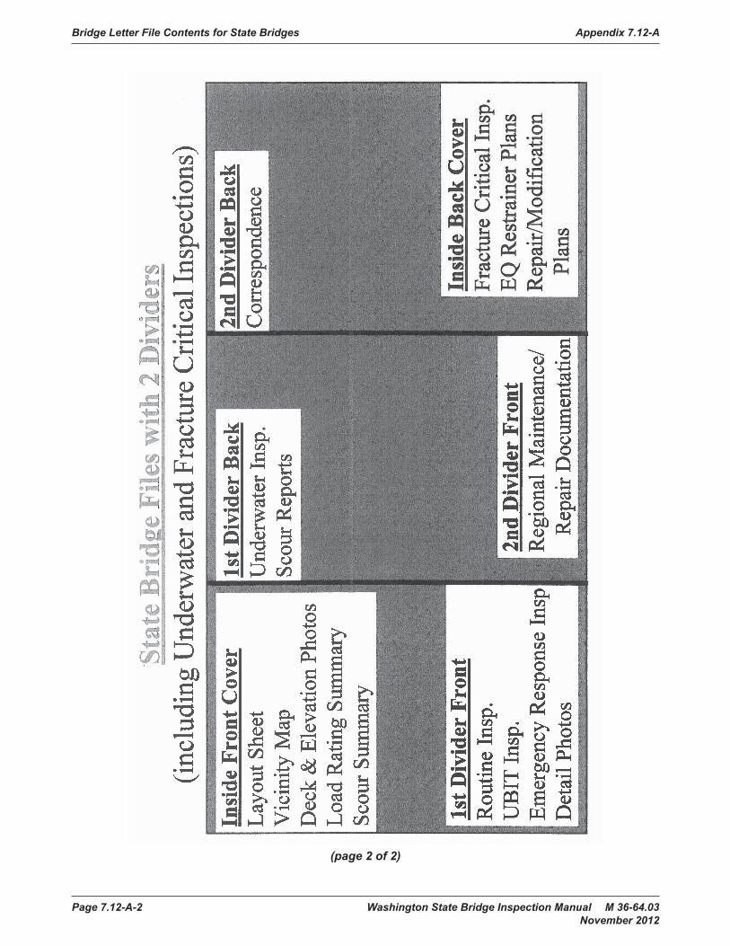
Bridge Letter File Contents for State Bridges Appendix 7.12-A
Page 7.12-A-2 Washington State Bridge Inspection Manual M 36-64.03 November 2012
(page 2 of 2)

Washington State Bridge Inspection Manual M 36-64.03 Page 7.12-B-1 November 2012
Appendix 7.12-B Flowchart for Tracking New Bridges
Bridge
Inve
ntory Flow
DSB
Contract data en
tered into Con
tract T
racking DB
SAL
(all contracts)
GB
Other Data Sources
From
Bid Ope
nings
Iden
tify & con
tact
GFC
* Bu
ilders E
xchange
↓Project E
ngineer
BDJ
*Project web
site
↓BT
*CCIS
↓HB
Download Aw
ard Plans &
Spe
c from
Prin
t Services
Iden
tify & re
cord Expected
to AFM
/Con
tract P
lans
Completion/op
ening date
↓ ↓Initial re
view
of p
lans fo
r brid
ge re
lated work
↓Co
nfirm
review
of all contracts for brid
ge
related work & I.D. actual plan sheets Q
/CScou
r data to/
↓from
Scour Engineer
↓Extract &
Process Award plans
↓Plan
sheet Q
/CLoad
Rating data from
Create new
record in
Brid
ge W
orks
Load
plans to
Brid
ge W
orks
Load
Rating Engine
er6 mos ‐ 1 year prio
r to expe
cted
com
pletion
↓Crossin
g Re
cords review
BMS Elem
ent review
↓Ch
eck for relevant
Dive Inspectio
n Ch
ange Orders/CR
IPs
Notificatio
n↓
GIS Data
↓Mon
itor b
ridges for Ope
ning
Date
↓Final review & re
lease to Brid
geWorks
↓ ↓1 mon
th prio
r to traffic
Layout to
Rom
an/Craig
Structure placed
in "GO IN
SPEC
T" Status
Check for relevant
for review if UBIT/Bu
cket
in Con
tract T
racking DB
Change Orders/CR
IPs
↓ ↓Inspectio
n Sche
duled
C:\U
sers\Byw
aterj\Do
cumen
ts\Brid
ge Preservation Managem
ent\QC\QC Manual\U
nit‐C&
A\Co
py of B
ridge Inventory Flow
.xlsx
2/14/20
12

Flowchart for Tracking New Bridges Appendix 7.12-B
Page 7.12-B-2 Washington State Bridge Inspection Manual M 36-64.03 November 2012

Washington State Bridge Inspection Manual M 36-64.03 Page 7.12-C-1 November 2012
Appendix 7.12-C Bridge Preservation Office Floor Plan
Bridge Preservation Office Floor Plan Appendix 7.12-C
Page 7.12-C-2 Washington State Bridge Inspection Manual M 36-64.03 November 2012

Washington State Bridge Inspection Manual M 36-64.03 Page 7.12-D-1 November 2012
WSBIS Fields Maintained With Other Appendix 7.12-D WSDOT Database Source Information
1. Fields that BPO would like to get from TDO to check for NBI submittal:
hwy_class (char(1), null) – This code identifies what type of highway the inventoried route is one using the following:
1 Interstate highway 2 U.S. numbered highway 3 State Highway 4 County road 5 City street 6 Federal lands road 7 State lands road 8 Other (included toll roads not otherwise identified.)
serv_level_code(char(1), null) – This code describes the designated level of service provided by the inventoried route:
1 Mainline (most local agency bridges) 2 Alternate 3 Bypass 4 Spur 6 Business 7 Ramp or “Y” 8 Service and/or unclassified Frontage Road 0 None of the above
When two or more routes are concurrent, the highest class of route will be used. The hierarchy is as listed above
adt(numeric(6,0), null) – This is the Average Daily Traffic (ADT) volume carried on the route being inventoried. If bridges on a divided highway are coded as parallel, then the ADT is the volume carried on the individual bridge, not the cumulative volume carried on the route. The determined ADT volume must be no more than four (4) years old. Add leading zeros to fill all spaces in the field.
adt_truck_pct (numeric(2,0),null) – This is the percentage of the ADT volume that is truck traffic. It does not include vans, pickups, or other light delivery trucks. Code to the nearest whole percent.
adt_year(numeric(4,0), null) – This is the year in which the estimate of the ADT volume was determined. If the year entered in this field is more than four years in the past, a new ADT volume must be determined and entered in the ADT and the year the ADT was determined in this field.

WSBIS Fields Maintained With Other WSDOT Database Source Information Appendix 7.12-D
Page 7.12-D-2 Washington State Bridge Inspection Manual M 36-64.03 November 2012
Future_adt(numeric(6,0), null) – This is the ADT volume that the inventory route is expected to carry 20 years in the future. This field may be updated whenever a new projection is made. The field must be updated any time the projected date of this forecast is less than 17 years, but not more than 22 years from the current year.
Future_adt_year(numeric(4,0), null) – This is the year for which future_adt has been projected. This date must be at least 17, but no more than 22 years from the current year. If the date in this field is outside these limits, then a new value will be required for and a new year will need to be entered in this field.
strahnet_hwy(char(1),null – For the inventory route identified indicate STRAHNET highway status using one of the following codes:
0 The inventory route is not a STRAHNET highway. 1 The inventory route is an Interstate STRAHNET highway. 2 The inventory route is a non-Interstate STRAHNET highway. 3 The inventory route connects with a Department of Defense facility.
nat_truck_ntwrk_flag(char(1),null)
fed_hwy_system_code(char(1),null) – This item shall be coded for all records in the inventory. For the inventory route identified indicate whether the inventory route is on the NHS or not on that system. This code shall reflect an inventory route on the NHS as described in the TRANSPORTATION EQUITY ACT FOR THE 21ST CENTURY (TEA21).
If more than one federal aid highway is carried on or under the bridge, indicate only the classification of the more primary route.
0 Inventory Route is not on the NHS. 1 Inventory Route is on the NHS.
fed_functional_class(class(2),null) – This code describes the Federal Functional classification of the inventory route as classified according to Statewide National Functional Classification System maps. Statewide National Functional Classification System maps are located at local agency planning departments or WSDOT Service Center Planning.
Separate codes are used to distinguish roadways located in rural or in urban areas. Routes shall be coded rural if they are not inside a designated urban area, Codes 08, 09, and 19 are for off-system roads.
Rural Codes 01 Principal Arterial – Interstate
02 Principal Arterial – Other 06 Minor Arterial 07 Major Collector (Federal Aid Secondary) 08 Minor Collector 09 Local

Appendix 7.12-D WSBIS Fields Maintained With Other WSDOT Database Source Information
Washington State Bridge Inspection Manual M 36-64.03 Page 7.12-D-3 November 2012
Urban Codes 11 Principal Arterial – Interstate
12 Principal Arterial – Other Freeway or Expressway 14 Other Principal Arterial 16 Minor Arterial 17 Collector 19 Local
fed_lands_hwy_code(char(1),null) – This code identifies bridges on roads which lead to and traverse through federal lands. These bridges may be eligible to receive funding from the Federal Lands Highway Program.Use one of the following codes:
0 Not Applicable 1 Indian Reservation Road (IRR) 2 Forest Highway (FH) 3 Land Management Highway System (LMHS) 4 Both IRR and FH 5 Both IRR and LMHS 6 Both FH and LMHS 9 Combined IRR, FH, and LMHS
For definition of IRR (Indian Reservation Roads), see Title 23 USC Section 101.
2. Fields BPO would like to get from TDO if available:
Region_code(char(2),null) – This is a two-digit code, which identifies the WSDOT region in which the bridge is located.
County_id(int,null) – This is a two-digit code, which identifies the county in which the bridge is located. If this is a jointly owned bridge, the county that is responsible for reporting the data to the inventory should be entered here. Use one of the following codes.
City_id(int,null) – This is the city in which the bridge is located. (Codes for cities and towns are identified according to the most recent U.S. Bureau of the Census Identification Schedule.) Contact the Bridge Engineer for Local Agencies for newly incorporated municipalities.If the bridge is outside of corporate limits or in an unincorporated city, code all zeros.
Leg_dist_code_1(int, null) – This field identifies the first or only State Legislative District in which the bridge is located.If the legislative district number is followed by a letter (District 19A, for example), disregard the letter and enter the two-digit number only
Leg_dist_code_2(int, null) – For bridges which span a State Legislative District dividing line, use this field to identify the second State Legislative District number.Use both this and the Legislative District Number (1) field to enter the two separate State Legislative District numbers. If no code is applicable, enter all zeroes.
WSBIS Fields Maintained With Other WSDOT Database Source Information Appendix 7.12-D
Page 7.12-D-4 Washington State Bridge Inspection Manual M 36-64.03 November 2012
speed_limit(tinyint, null) – Speed limit on the bridge.
• These are coming from the Data Mart process…an ARM value is returned as well.
• These are going to be populated by HPMS.

Washington State Bridge Inspection Manual M 36-64.03 Page 7.12-E-1 November 2012
Bridge Preservation Office Appendix 7.12-E Lead Approval Criteria
Please use the following criteria to help you determine which reports can be sent directly to the Bridge Information Group without further review by a supervisor or a second Lead.
A “Bridge Inspection Report” that fits any one of the following nine criteria must be reviewed by a Regional Bridge Inspection Engineer or a second Lead Inspector.
1. If NBI codes for Deck Overall, Superstructure or Substructure are less than “6”.
2. Structures with repairs or conditions to be monitored.
3. New bridge structures (Inventory Inspections).
4. Fracture Critical bridges.
5. Local Agency bridges.
6. UBIT Bridge Inspections.
7. Any inspection with a frequency >24 months.
8. Any bridge that is currently having issues with scour.
9. Any time an inspection/report type and/or frequency is either changed, added, or deleted.
Additionally, the Lead may submit for review any report that the Lead feels needs further input from the Regional Bridge Inspection Engineer.
If the “Bridge Inspection Report” does not meet any of these criteria, then the “Bridge Inspection Report” can be routed by the experienced Lead Inspector to the Info Group for processing.
For quality assurance reasons, the “Bridge Inspection Report” can be randomly reviewed at the Regional Bridge Inspection Engineer’s option.

Bridge Preservation Office Lead Approval Criteria Appendix 7.12-E
Page 7.12-E-1 Washington State Bridge Inspection Manual M 36-64.03 November 2012
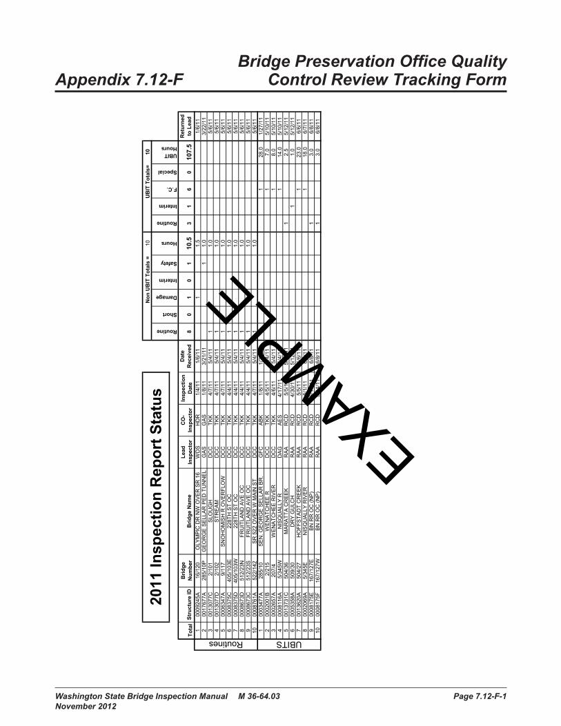
Washington State Bridge Inspection Manual M 36-64.03 Page 7.12-F-1 November 2012
Bridge Preservation Office Quality Appendix 7.12-F Control Review Tracking Form
Exam
ple
of a
QC
Offi
ce R
evie
w T
rack
ing
Form
1010
Tota
lSt
ruct
ure
IDB
ridge
N
umbe
rB
ridge
Nam
eLe
ad
Insp
ecto
rC
O-
Insp
ecto
rIn
spec
tion
Dat
eD
ate
Rec
eive
d8
01
01
10.5
31
60
107.
5R
etur
ned
to L
ead
100
0924
5A16
/120
OLY
MP
IC D
R N
W O
VE
R S
R 1
6W
DS
HD
R1/
4/11
1/6/
111
1.5
1/6/
112
0017
677A
285/
10P
GE
OR
GE
SE
LLA
R P
ED
TU
NN
EL
GA
SG
AS
1/8/
113/
21/1
11
1.0
3/22
/11
300
1307
7C 2
/101
SLO
UG
HD
CC
TKK
4/7/
115/
4/11
11.
05/
6/11
400
1307
7D 2
/102
STR
EA
MD
CC
TKK
4/7/
115/
4/11
11.
05/
6/11
500
0634
7A 9
/117
SN
OH
OM
ISH
R O
VE
RFL
OW
DC
CTK
K4/
7/11
5/4/
111
1.0
5/6/
116
0008
375C
405/
103E
228T
H S
T O
CD
CC
TKK
4/4/
115/
4/11
11.
05/
6/11
700
0837
5D40
5/10
3W22
8TH
ST
OC
DC
CTK
K4/
4/11
5/4/
111
1.0
5/6/
118
0008
673D
512/
23N
FRU
ITLA
ND
AV
E O
CD
CC
TKK
4/4/
115/
4/11
11.
05/
6/11
900
0867
3C51
2/23
SFR
UIT
LAN
D A
VE
OC
DC
CTK
K4/
4/11
5/4/
111
1.0
5/6/
1110
0008
761A
522/
142
SR
522
OV
ER
W M
AIN
ST
DC
CTK
K4/
7/11
5/4/
111
1.0
5/6/
111
0003
477A
285/
10S
EN
. GE
OR
GE
SE
LLA
R B
R.
GFC
AB
K1/
8/11
1/27
/11
128
.01/
27/1
12
0002
001B
2/2
15W
EN
ATC
HE
E R
DC
CTK
K4/
5/11
5/4/
111
7.0
5/10
/11
300
0265
7A20
7/4
WE
NA
TCH
EE
RIV
ER
DC
CTK
K4/
6/11
5/4/
111
8.0
5/10
/11
400
0811
6A 5
/345
WN
ISQ
UA
LLY
RD
AG
AE
S4/
17/1
15/
4/11
114
.05/
10/1
15
0013
731C
504/
36M
AR
ATT
A C
RE
EK
RA
AR
CD
5/5/
115/
12/1
11
2.5
5/12
/11
600
0535
8A50
9/30
DR
Y G
ULC
HR
AA
RC
D4/
30/1
15/
12/1
11
1.0
5/12
/11
700
1362
0A50
4/27
HO
FFS
TAD
T C
RE
EK
RA
AR
CD
5/5/
116/
6/11
123
.06/
6/11
800
0206
9A5/
345E
NIS
QU
ALL
Y R
IVE
RR
AA
RC
D5/
1/11
6/6/
111
18.0
6/7/
119
0008
175E
167/
127E
BN
RR
OC
(NP
)R
AA
RC
D5/
14/1
16/
8/11
13.
06/
8/11
1000
0817
5F16
7/12
7WB
N R
R O
C (N
P)
RA
AR
CD
5/14
/11
6/8/
111
3.0
6/8/
11
UBIT Hours
Routine
Short
Damage
Interim
Safety
Hours
Routine
Interim
UBITSRoutines
Non
UB
IT T
otal
s =
2011
Insp
ectio
n R
epor
t Sta
tus
F.C.
UB
IT T
otal
s= Special
EXAMPLE

Bridge Preservation Office Quality Control Review Tracking Form Appendix 7.12-F
Page 7.12-F-2 Washington State Bridge Inspection Manual M 36-64.03 November 2012

Washington State Bridge Inspection Manual M 36-64.03 Page 7.12-G-1 November 2012
Bridge Preservation Office Quality Appendix 7.12-G Control Report Review Tracking Form
201
1 R
EPO
RT
REV
IEW
STA
TUS
REV
IEW
DAT
ER
EPO
RT
DAT
E00
6/11
5IN
SPEC
TOR
APPR
OVA
L ST
ATU
SC
OM
MEN
TS03
/26
02/2
800
6/10
1FP
P/W
AW
AA
N03
/29
03/1
909
9/54
0NB
DC
C/G
AS
AA
N03
/29
03/1
909
9/54
0SB
DC
C/G
AS
AA
N03
/30
03/2
009
9/54
0W-S
DC
C/G
AS
AP
PR
OV
ED
03/3
003
/07
0850
7600
WD
S/A
ES
AA
NLA
Cen
tralia
03/3
003
/21
0803
9100
WD
S/T
JNA
PP
RO
VE
DLA
Klic
kita
t Cou
nty
03/3
003
/21
0811
8500
WD
S/T
JNA
AN
LA K
licki
tat C
ount
y03
/30
03/0
808
2012
00W
DS
/AE
SA
AN
LA L
ewis
Cou
nty
03/3
103
/24
0864
7200
WD
S/S
MP
AA
NLA
Sta
te P
arks
03/3
103
/23
0827
6000
WD
S/T
JNA
AN
LA C
lark
Cou
nty
03/3
103
/22
0012
160A
WD
S/T
JNA
AN
LA S
kam
ania
Cou
nty
03/3
103
/22
0821
8700
WD
S/T
JNA
AN
LA K
licki
tat C
ount
y03
/31
03/0
708
2884
00JE
D/T
JNA
AN
LA Y
akim
a C
ount
y04
/01
03/0
808
3969
00JE
D/T
JNA
AN
LA Y
akim
a C
ount
y04
/01
03/0
708
6510
00JE
D/T
JNA
AN
LA Y
akim
a C
ount
y04
/04
03/1
708
2717
00D
AG
/TJN
AA
NLA
Cow
litz
Cou
nty
04/0
403
/15
0855
7500
DA
G/T
JNA
AN
LA L
ongv
iew
04
/04
03/1
508
5584
00D
AG
/TJN
AA
NLA
Lon
gvie
w
04/0
403
/03
0009
236C
DA
G/T
KK
AP
PR
OV
ED
LA C
owlit
z C
ount
y04
/05
03/0
316
7/11
2WD
AG
/TK
KA
AN
04/0
502
/28
167/
110
DA
G/T
KK
AA
N04
/05
03/0
316
7/11
6D
AG
/TK
KA
PP
RO
VE
D04
/05
03/0
316
7/11
2W-N
DA
G/T
KK
AA
N04
/05
03/0
316
7/11
1W-N
DA
G/T
KK
AA
N04
/05
03/0
216
7/12
3WD
AG
/TK
KA
AN
04/0
503
/02
167/
129
DA
G/T
KK
AA
N04
/05
03/0
216
7/13
1.25
DA
G/T
KK
AA
N04
/05
03/2
800
1075
6AD
AG
/HD
RA
AN
LA C
owlit
z C
ount
y04
/05
03/2
908
4923
00D
AG
/HD
RA
AN
LA C
owlit
z C
ount
y04
/05
03/1
400
0309
3AD
AG
/TJN
AA
NLA
Kel
so04
/06
03/0
908
2302
00W
DS
/AE
SA
AN
LA C
owlit
z C
ount
y04
/06
03/3
108
1641
00D
AG
/?A
AN
LA C
owlit
z C
ount
y04
/06
03/0
300
5/62
6.5A
JHL/
RC
DA
PP
RO
VE
D04
/06
03/0
102
0/22
3NJH
L/R
CD
AP
PR
OV
ED
04/0
603
/02
005/
706
JHL/
RC
DA
AN
04/0
603
/03
005/
651W
JHL/
RC
DA
AN
void
und
er s
outh
app
roac
h04
/06
03/0
200
5/70
8JH
L/R
CD
AA
N04
/06
03/0
300
5/72
6EJH
L/R
CD
AP
PR
OV
ED
EXAMPLE

Bridge Preservation Office Quality Control Report Review Tracking Form Appendix 7.12-G
Page 7.12-G-2 Washington State Bridge Inspection Manual M 36-64.03 November 2012

Washington State Bridge Inspection Manual M 36-64.03 Page 7.12-H-1 November 2012
Bridge Preservation Office Appendix 7.12-H Quality Control Field Review Form
Field Review 2012 WASHINGTON STATEQUALITY CONTROL REVIEW
Bridge Number: Bridge Name:Inspectors: QC Reviewer:Inspection Date:Frequency:Previous Report Date
Description of Quality Control Method
Are all the applicable FHWA items for the structure properly coded? Yes _____ No _____
Are all the BMS elements for the structure correctly identified? Yes _____ No _____
Are all the BMS element condition states for the structure properly coded? Yes _____ No _____
Do the BMS codes support the NBI Codes? Yes _____ No _____
(page 1 of 2)

Bridge Preservation Office Quality Control Field Review Form Appendix 7.12-H
Page 7.12-H-2 Washington State Bridge Inspection Manual M 36-64.03 November 2012
Field Review 2012 WASHINGTON STATEQUALITY CONTROL REVIEW
Bridge Number: Bridge Name:Inspectors: QC Reviewer:Inspection Date:Does the verbiage within the report support the condition states? Yes _____ No _____
Were proper safety procedures practiced? Yes _____ No _____
Are the existing repairs supported by the inspection findings? Yes _____ No _____
Are improvement processes necessary? Yes _____ No _____
(page 2 of 2)
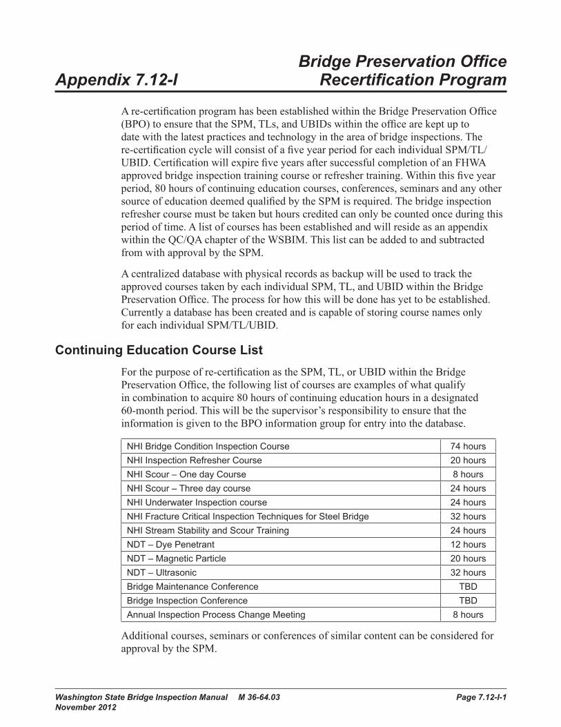
Washington State Bridge Inspection Manual M 36-64.03 Page 7.12-I-1 November 2012
Bridge Preservation Office Appendix 7.12-I Recertification Program
A re-certification program has been established within the Bridge Preservation Office (BPO) to ensure that the SPM, TLs, and UBIDs within the office are kept up to date with the latest practices and technology in the area of bridge inspections. The re-certification cycle will consist of a five year period for each individual SPM/TL/UBID. Certification will expire five years after successful completion of an FHWA approved bridge inspection training course or refresher training. Within this five year period, 80 hours of continuing education courses, conferences, seminars and any other source of education deemed qualified by the SPM is required. The bridge inspection refresher course must be taken but hours credited can only be counted once during this period of time. A list of courses has been established and will reside as an appendix within the QC/QA chapter of the WSBIM. This list can be added to and subtracted from with approval by the SPM.
A centralized database with physical records as backup will be used to track the approved courses taken by each individual SPM, TL, and UBID within the Bridge Preservation Office. The process for how this will be done has yet to be established. Currently a database has been created and is capable of storing course names only for each individual SPM/TL/UBID.
Continuing Education Course ListFor the purpose of re-certification as the SPM, TL, or UBID within the Bridge Preservation Office, the following list of courses are examples of what qualify in combination to acquire 80 hours of continuing education hours in a designated 60-month period. This will be the supervisor’s responsibility to ensure that the information is given to the BPO information group for entry into the database.
NHI Bridge Condition Inspection Course 74 hoursNHI Inspection Refresher Course 20 hoursNHI Scour – One day Course 8 hoursNHI Scour – Three day course 24 hoursNHI Underwater Inspection course 24 hoursNHI Fracture Critical Inspection Techniques for Steel Bridge 32 hoursNHI Stream Stability and Scour Training 24 hoursNDT – Dye Penetrant 12 hoursNDT – Magnetic Particle 20 hoursNDT – Ultrasonic 32 hoursBridge Maintenance Conference TBDBridge Inspection Conference TBDAnnual Inspection Process Change Meeting 8 hours
Additional courses, seminars or conferences of similar content can be considered for approval by the SPM.

Bridge Preservation Office Recertification Program Appendix 7.12-I
Page 7.12-I-1 Washington State Bridge Inspection Manual M 36-64.03 November 2012
Documents available as reference and training material include but are not limited to the following:
• Washington State Bridge Inspection Manual (WSBIM) including annually updated Best practices(guidelines)
• Bridge Inspection Reference Manual (BIRM)
• The Manual for Bridge Evaluation (MBE)
• Timber Bridges Manual (USDA)

Washington State Bridge Inspection Manual M 36-64.03 Page 7.12-J-1 November 2012
Bridge Preservation Office Quality Appendix 7.12-J Assurance Bridge Selection Process
The following table identifies categories used to help evaluate whether or not the random selection is representative sample of the previous seasons inspections. If a particular category is not considered to be covered sufficiently, additional bridges can be traded out in order to establish more representative coverage. The selection set for the office and field review will include a minimum of 100 bridges of the previous year’s inspections. The final list developed prior to generating a random sample is screened for inspection types that consist of Routine, Safety or Short Span type inspections. The list is also screened for bridges that have been previously QA’d. Once a final list of bridges is developed, a random list is generated. The first 100 bridges are selected and represent the final short list for QA office and field review for that year. This final short list is then validated for reasonable representation of the categories listed below.
As an option, a minimum of five bridges previously receiving a quality assurance review, excluding work from the previous QA inspection season, can be added to the final short list for the season. The goal of doing this is to validate whether or not suggested changes in the report that reflect correct office procedures and federal requirements have been implemented or not. These bridges may be chosen by the QA Engineer to best fit within proximities of the randomly selected bridges.
Region Scour Code
Primary Material Type Open/Closed/Posted
Primary Design Type Year Built
Inspection Type Inspection Frequency
By Team Leader NBI Reportable
Sufficiency Rating Bridge Length
Structurally Deficient/Functionally Obsolete (SD/FO)
BPO Scope of Field ReviewThe selection process above does not eliminate any bridges because of size or complexity. The typical bridge will be inspected in its entirety. However, the scope of field review for larger and more complex bridges is entirely a different matter. The process for QA inspection for these types of structures will be more case by case. The idea will be that some of all of the components for these particular bridges will be inspected. The QA process should consider both time and size in determining how to reach this goal for these types of bridges. Traffic windows, lane closure manpower, species windows, and equipment availability are other factors that will influence the ability for one QA team to accomplish a smaller scale inspection of a larger more complex structure.

Bridge Preservation Office Quality Assurance Bridge Selection Process Appendix 7.12-J
Page 7.12-J-2 Washington State Bridge Inspection Manual M 36-64.03 November 2012

Washington State Bridge Inspection Manual M 36-64.03 Page 7.12-K-1 November 2012
Bridge Preservation Appendix 7.12-K Office Field Review
The following is a list of contents in a typical bridge file for structures owned by the State of Washington which also includes Washington State Ferries (WSF) structures.
• Letter file contents include:
• Deck and Elevation Photos (More recent photos are stored on BEISt)
• Vicinity map
• Load Rating summary sheet
• Scour Summary sheet**
• Signed Inspection reports
• Fracture Critical report*
• Underwater (U/W) report*
• WSBIS forms (in file drawer)
• Correspondence
• Maintenance records
• Plan sheets (Most plans are stored on BEISt)
*For bridges with underwater and/or fracture critical inspections. **For bridges over water.

Bridge Preservation Office Field Review Appendix 7.12-K
Page 7.12-K-2 Washington State Bridge Inspection Manual M 36-64.03 November 2012

Washington State Bridge Inspection Manual M 36-64.03 Page 7.12-L-1 November 2012
Bridge Preservation Office Appendix 7.12-L Decertification/Reinstatement
Currently under development.

Bridge Preservation Office Decertification/Reinstatement Appendix 7.12-L
Page 7.12-L-2 Washington State Bridge Inspection Manual M 36-64.03 November 2012

Washington State Bridge Inspection Manual M 36-64.03 Page 7.12-M-1 November 2012
H&LP Continued Certification Appendix 7.12-M of Bridge Inspection Personnel
A continued certification of bridge inspection personnel program has been established to ensure that all program managers, team leaders, load raters, and underwater bridge inspection divers are kept up to date with the latest practices and technology in the area of bridge inspections. This continued certification program requires that each Certified Bridge Inspector (CBI) must participate in the following during a five-year period to maintain certification:
• 40 hours of bridge related continuing education courses and training including WSDOT sponsored bridge training, bridge conferences and other NHI bridge training courses.
• An approved Bridge Inspector Refresher Training course. The hours credited can only be counted once during this five-year period of time.
• Successful field evaluations performed by WSDOT H&LP during QA reviews or by an agency’s Bridge Program Manager with the approval of the WSDOT Local Agency Bridge Engineer (see Section 34.3) for recertification and qualification status.
Continued Certification Course and Training ListThe following is a list of courses that are examples of what would qualify in combination to acquire 40 hours of continuing education hours in the designated five-year period. It is the inspector’s responsibility to ensure that the information is given to their local agency program manager or the H&LP Bridge Engineer within the necessary timeframes to ensure continued certification.
WSDOT/LTAP – Bridge Condition Inspection Fundamentals (BCIF) 24 hours
WSDOT/LTAP – Bridge Condition Inspection Training (BCIT) 72 hours
WSDOT/LTAP – Bridge Condition Inspection Update (BCIU) 16 hours
WSDOT/LTAP – Bridge Inventory Coding 18 hours
NHI Bridge Condition Inspection Course 74 hours
NHI Inspection Refresher Course 20 hours
NHI Scour – One Day Course 8 hours
NHI Scour – Three Day Course 24 hours
NHI Underwater Inspection Course 24 hours
NHI Fracture Critical Inspection Techniques for Steel Bridge 32 hours
Pacific NW Bridge Maintenance Conference 16 hours
Pacific NW Bridge Inspection Conference 16 hours

H&LP Continued Certification of Bridge Inspection Personnel Appendix 7.12-M
Page 7.12-M-2 Washington State Bridge Inspection Manual M 36-64.03 November 2012

Washington State Bridge Inspection Manual M 36-64.03 Page 7.12-N-1 November 2012
H&LP Certification Suspension Appendix 7.12-N and Reinstatement
H&LP has established a suspension and reinstatement of certification process to ensure that all program managers, team leaders, load raters, and underwater bridge inspection divers are kept up to date with the certification program requirements that each Certified Bridge Inspector (CBI) is required to meet.
If a CBI does not fulfill the requirements of Appendix 7.12-M, their certification will be suspended until the inspector supplies H&LP with proof that they have successfully fulfilled the continuing education requirements as outlined in Appendix 7.12-M.
If a Certified Bridge Inspector’s work is found to be deficient during a formal review, a plan of corrective action will be initiated.
This formal correction plan consists of the following:
A. The CBI will be notified by formal letter that a plan of corrective action is being initiated.
B. The Certified Bridge Inspector will be required to attend additional Bridge Inspector training classes beyond the continuing education requirements of Appendix 7.12-M as specified by H&LP to meet the individual needs of the CBI based on the deficiencies found. The CBI will also be provided additional field instruction by H&LP or by the Agency’s Bridge Program Manager.
C. A CBI who satisfactorily completes the plan of corrective action will be considered in good standing. A CBI who does not satisfactorily complete the plan of corrective action will have their certification suspended and will be required to re-certify under the requirements of Section 7.10.B.
When a CBI is suspended or reinstated, the H&LP Local Agency Bridge Engineer will notify the Statewide Program Manager (SPM) on the actions of suspension and reinstatement.

H&LP Certification Suspension and Reinstatement Appendix 7.12-N
Page 7.12-N-2 Washington State Bridge Inspection Manual M 36-64.03 November 2012

Washington State Bridge Inspection Manual M 36-64.03 Page 7.12-O-1 November 2012
Appendix 7.12-O H&LP Quality Assurance Deficiencies
H&LP has established a procedure for documenting and reporting deficiencies found during Quality Assurance reviews of a local agency.
If deficiencies exist, the local agency will be sent a letter or email requesting that any missing documentation be submitted or provide a plan of corrective action, for H&LP’s approval, to correct the deficiency within 60 days. This notification will be first in the form of email or other correspondence with the H&LP Bridge Office. If corrections are not made within 60 days of notification, the second notification will be a formal letter of non-compliance from the H&LP Engineering Services Manager.
Finally, failure to carry out the plan of corrective action will result in formal notification from the Director of H&LP that federal funds may be restricted until compliance is met. If continued deficiencies are found in subsequent reviews of the agency’s procedures, management practices, or systems, or if specific inspection errors continue, H&LP will work with the agency to further determine the cause of the problems and will recommend addition training for the both the Bridge Program Manager and the Bridge Inspection Team Leader
When a local agency is notified of deficiencies to correct, the H&LP Local Agency Bridge Engineer will notify and include the Statewide Program Manager (SPM) on all plans of corrective action and status updates to the plans of corrective action.

H&LP Quality Assurance Deficiencies Appendix 7.12-O
Page 7.12-O-2 Washington State Bridge Inspection Manual M 36-64.03 November 2012