washington metropolitan area transit authority - wmata.com · pdf fileastm e164, standard...
TRANSCRIPT
Washington Metropolitan Area Transit Authority
Volume # 2 CONTRACT SPECIFICATIONS
Divisions: 03, 05, 06, 07, 08, 15 &16. CONTRACT NO. FQ18063
REPLACE TREE ROOFSJGB (T19), CTF BLDG “A” (T38) AND RCF (C34).
December, 2017.
PAGE INTENTIONALLY LEFT BLANK
Washington Metropolitan Area Transit Authority Contract No. FQ18063 RFP- FQ18063/KKB Date: December 2017
TABLE OF CONTENTS
DIVISION 03 CONCRETE
03540
CAST UNDERLAYMENT
DIVISION 05 METALS
05120
STRUCTURAL STEEL FRAMING
05310 METAL DECKING
DIVISION 06 WOODS AND PLASTICS 06100 ROUGH CARPENTRY
DIVISION 07 THERMAL AND MOISTURE PROTECTION
07212 07532 07595 07620 07710 07900
BOARD INSULATION EPDM ROOFING PREPARATION FOR RE-ROOFING FLASHING AND SHEET METAL MANUFACTURED ROOF SPECIALTIES JOINT SEALERS
DIVISION 08 DOORS AND WINDOWS
08630
METAL-FRAMED SKYLIGHTS
DIVISION 15 MECHANICAL 15010 15425
MECHANICAL PROVISIONS, MATERIALS AND METHODS ROOF DRAINS
DIVISION 16 ELECTRICAL 16010 BASIC ELECTRICAL REQUIREMENTS
TABLE OF CONTENTS
Washington Metropolitan Area Transit Authority Contract No. FQ18063 RFP FQ18063/KKB Date: December 2017
PAGE INTENTIONALLY LEFT BLANK
Washington Metropolitan Area Transit Authority Contract No. FQ18063 RFP- FQ18063/KKB__ Date: December 2018
SECTION 03540
CAST UNDERLAYMENT
PART 1 GENERAL
1.01 SECTION INCLUDES
A. Liquid-applied self-leveling underlayment.
1. Use cementitious type at roof deck patching for concrete decks.
1.02 REFERENCE STANDARDS
A. ASTM C109/C109M - Standard Test Method for Compressive Strength of Hydraulic Cement Mortars (Using 2-in. or (50-mm) Cube Specimens); 2013.
B. ASTM C348 - Standard Test Method for Flexural Strength of Hydraulic-Cement Mortars; 2014.
C. ASTM E84 - Standard Test Method for Surface Burning Characteristics of Building Materials; 2014.
1.03 SUBMITTALS
A. See Contract Specifications General Requirements, for submittal procedures.
B. Product Data: Provide manufacturer's data sheets documenting physical characteristics and product limitations of underlayment materials. Include information on surface preparation, environmental limitations, and installation instructions.
C. Certificate: Certify that products meet or exceed specified requirements.
1.04 QUALITY ASSURANCE
A. Applicator Qualifications: Company specializing in performing the work of this section, and approved by manufacturer.
1.05 DELIVERY, STORAGE, AND HANDLING
A. Store products in manufacturer's unopened packaging until ready for installation.
B. Keep dry and protect from direct sun exposure, freezing, and ambient temperature greater than 105 degrees F (41 degrees C).
CAST UNDERLAYMENT 03540 - 1
Washington Metropolitan Area Transit Authority Contract No. FQ18063 RFP- FQ18063/KKB__ Date: December 2018
1.06 MOCK-UP
A. Provide a mock-up for evaluation of surface preparation techniques and application workmanship.
1. Prepare mock-up in location designated by COR.
2. Area: 6 ft by 6 ft (2 m by 2 m).
3. Do not proceed with patching until workmanship of mock-up has been approved by COR.
B. Mock-up may remain as part of the Work.
1.07 FIELD CONDITIONS
A. Do not install underlayment until floor penetrations and peripheral work are complete.
B. Maintain minimum ambient temperatures of 50 degrees F (10 degrees C) 24 hours before, during and 72 hours after installation of underlayment.
C. During the curing process, ventilate spaces to remove excess moisture.
PART 2 PRODUCTS
2.01 MANUFACTURERS
A. Cementitious Underlayment:
1. Fox Industries: FX32AEC
2. Or approved equal.
2.02 MATERIALS
A. Cast Underlayments, General:
1. Conform to applicable code for combustibility or flame spread requirements.
2. Provide certificate of compliance from authority having jurisdiction indicating approval of underlayment materials in the required fire rated assembly.
CAST UNDERLAYMENT 03540 - 2
Washington Metropolitan Area Transit Authority Contract No. FQ18063 RFP- FQ18063/KKB__ Date: December 2018
B. Cementitious Underlayment: Blended cement mix, that when mixed with water in accordance with manufacturer's directions will produce self-leveling underlayment with the following properties:
1. Compressive Strength: Minimum 6000 psi (27.6 MPa) after 28 days, tested per ASTM C 39.
2. Flexural Strength: Minimum 1000 psi (6.9 MPa) after 28 days, tested per ASTM C 293.
3. Bond Strength: 1,000 psi (12.3 MPa.
4. Splitting Tensile Strength ASTM C 496 7 days: 650 psi 4.48 MPa, 28 days: 800 psi 5.52 MPa
5. Thickness: Capable of thicknesses from feather edge to full depth.
6. Surface Burning Characteristics: Flame spread/Smoke developed index of 0/0 in accordance with ASTM E84.
C. Aggregate: Dry, well graded, washed silica aggregate, approximately 1/8 inch (3 mm) in size and acceptable to underlayment manufacturer.
D. Water: Potable and not detrimental to underlayment mix materials.
E. Bonding Agent: Manufacturer's recommended type, FX-752 or FX-792LPL.
2.03 MIXING
A. Site mix materials in accordance with manufacturer's instructions.
B. Add aggregate for areas where thickness will exceed 1/2 inch (12.7 mm). Mix underlayment and water for at least two minutes before adding aggregate, and continue mixing to assure that aggregate has been thoroughly coated.
C. Mix to self-leveling consistency without over-watering.
PART 3 EXECUTION
3.01 EXAMINATION
A. Verify that substrate surfaces are clean, dry, unfrozen, do not contain petroleum byproducts, or other compounds detrimental to underlayment material bond to substrate.
CAST UNDERLAYMENT 03540 - 3
Washington Metropolitan Area Transit Authority Contract No. FQ18063 RFP- FQ18063/KKB__ Date: December 2018
3.02 PREPARATION
A. Concrete: Mechanically prepare steel troweled concrete to create a textured surface necessary to achieve the best bond; acceptable methods include bead blasting and scarifying. Do not use acid etching.
B. Remove substrate surface irregularities. Fill voids and deck joints with filler. Finish smooth.
C. Vacuum clean surfaces.
D. Prime substrate in accordance with manufacturer's instructions. Allow to dry.
3.03 APPLICATION
A. Install underlayment in accordance with manufacturer's instructions.
3.04 CURING
A. Once underlayment starts to set, prohibit foot traffic until final set has been reached.
B. Air cure in accordance with manufacturer's instructions.
3.05 FIELD QUALITY CONTROL
A. Placed Material: Contractor will inspect and test for conformance to specification requirements.
3.06 PROTECTION
A. Protect against direct sunlight, heat, and wind; prevent rapid drying to avoid shrinkage and cracking.
B. Do not permit traffic over unprotected floor underlayment surfaces.
END OF SECTION
CAST UNDERLAYMENT 03540 - 4
Washington Metropolitan Area Transit Authority Contract No. FQ18063 RFP- FQ18063/KKB Date: December 2018
SECTION 05120
STRUCTURAL STEEL FRAMING
PART 1 GENERAL
1.01 SECTION INCLUDES
A. This Section covers the design, fabrication, and installation of structural metal framing.
1.02 RELATED SECTIONS
A. Section 05310: Steel Decking.
1.03 REFERENCES
A. American Institute of Steel Construction (AISC): 1. AISC 360; Specification for Structural Steel Buildings. 2. AISC 303; Code of Standard Practice for Steel Buildings and Bridges. 3. Specification for Structural Joints Using High-Strength Bolts (approved by Research Council
on Structural Connections, December 2009).
B. American National Standards Institute (ANSI): 1. ANSI B18.22.1, Plain Washers.
C. ASTM International (ASTM): 1. ASTM A36, Standard Specification for Carbon Structural Steel. 2. ASTM A53, Standard Specification for Pipe, Steel, Black and Hot-Dipped, Zinc-Coated,
Welded and Seamless. 3. ASTM A108, Standard Specification for Steel Bar, Carbon and Alloy, Cold-Finished. 4. ASTM A123, Standard Specification for Zinc (Hot-Dip Galvanized) Coatings on Iron and
Steel Products. 5. ASTM A325, Standard Specification for Structural Bolts, Steel, Heat Treated, 120/105 ksi
Minimum Tensile Strength. 6. ASTM A500, Standard Specification for Cold-Formed Welded and Seamless Carbon Steel
Structural Tubing in Rounds and Shapes. 7. ASTM A563, Standard Specification for Carbon and Alloy Steel Nuts. 8. ASTM A572, Standard Specification for High-Strength Low-Alloy Columbium-Vanadium
Structural Steel. 9. ASTM A780, Standard Practice for Repair of Damaged and Uncoated Areas of Hot-Dip
Galvanized Coatings. 10. ASTM A992, Standard Specifications for Structural Steel Shapes. 11. ASTM E164, Standard Practice for Contact Ultrasonic Testing of Weldments. 12. ASTM E709, Standard Guide for Magnetic Particle Testing. 13. ASTM F436, Standard Specification for Hardened Steel Washers. 14. ASTM F959, Standard Specification for Compressible-Washer-Type Direct Tension
Indicators for Use with Structural Fasteners. 15. ASTM F1554, Standard Specification for Anchor Bolts, Steel, 36, 55, and 105 ksi Yield
Strength. 16. ASTM F1852, Standard Specification for “Twist Off” Type Tension Control Structural
Bolt/Nut/Washer Assemblies, Steel, Heat Treated, 120/105 ksi Minimum Tensile Strength.
STRUCTURAL STEEL FRAMING 05120 - 1
Washington Metropolitan Area Transit Authority Contract No. FQ18063 RFP- FQ18063/KKB Date: December 2018
17. ASTM F2329, Standard Specification for Zinc Coating, Hot Dip, Requirements for
Application to Carbon and Alloy Steel Bolts, Screws, Washers, Nuts, and Special Threaded Fasteners.
D. American Welding Society (AWS): 1. AWS D1.1 Structural Welding Code - Steel.
E. SSPC ;The Society for Protective Coatings: 1. SSPC Painting Manual.
1.04 SUBMITTALS
A. Structural Steel Shop Drawings: 1. Submit shop drawings identifying the details as indicated on Drawings, indicating completely
the location in the project, the size and weights of the members, the methods of joining various components, the quantity, finish, the location and type of anchors and necessary measurements.
2. Provide easy-to-read markings on shop and erection drawings for shop assemblies which require markings for erection identification.
3. Note on shop drawings variations in tolerances or clearances between various products. 4. Use standard welding symbols of the AWS on shop drawings; show size, length, and type of
each weld. 5. Provide shop drawings prepared under the supervision of and sealed by a Professional
Engineer licensed in the Commonwealth of Pennsylvania experienced in structural engineering.
B. Working Drawings: 1. Furnish setting diagrams, templates, and directions for the installation of structural framing
anchor bolts, bearing plates, and other embedded items.
C. Project Standards: 1. Submit standards for typical beam, girder, column splices, and moment connection details
prior to submitting detail drawings; standards shall be prepared under the supervision of and sealed by a Professional Engineer licensed in the Commonwealth of Pennsylvania.
D. Connection Calculations: 1. Design all connections in accordance with AISC Specifications for Structural Steel Buildings
Using Allowable Strength Design. 2. Submit calculations prepared and sealed by a Professional Engineer, licensed in the
Commonwealth of Pennsylvania and experienced in structural engineering. 3. Use type of shop and field connections shown or, in absence of such indication, use the
most appropriate type. Connections shall safely withstand the combined effects of shears, direct forces, moments, and torques at applicable design stresses.
4. Connection details shown on the drawings are illustrative only. 5. Design and detail connections so interference does not occur with architectural clearance
lines and finishes. 6. One-sided or other eccentric connections are not permitted unless detailed on the Contract
Drawings.
E. Product Data: 1. Submit data for approval related to the following:
STRUCTURAL STEEL FRAMING 05120 - 2
Washington Metropolitan Area Transit Authority Contract No. FQ18063 RFP- FQ18063/KKB Date: December 2018
a. For items defined in Paragraph 2.01B this specification. b. Welding electrodes. c. Headed type studs. d. Paint primer.
F. Welding Certifications: 1. Prior to commencing work requiring welding, submit the procedure which will be used for
prequalifying welders and welding procedures. For all procedures other than those set forth in AWS D1.1, submit a copy of procedure qualification test records.
2. Submit certified copy of qualification test record showing each welder, welding operator, and tacker who will be employed in the work has satisfactorily passed AWS qualification tests for welding procedures.
3. Submit certified copy of reports for all analyses and tests required by referenced ASTM Specifications, including test reports for filler metals for welding, and mechanical tests for high-strength threaded fasteners.
G. Test Results: 1. Submit reports signed by the manufacturer certifying their products comply with
requirements specified. 2. Submit test reports certifying material conforms to ASTM specification. 3. Submit guarantee showing all steel used for this project is American-made. 4. Submit written affidavits from steel manufacturer indicating the percentage of post-industrial
recycled content (90% min.) and post-consumer recycled content (75% min.).
H. Qualification Statement: 1. Submit qualification statement denoting the requirements of this specification are met by the
following: a. Structural steel fabricator qualifications b. Structural steel erector qualifications c. Professional Land Surveyor d. Hot-Dip Galvanizing Company.
I. An Independent Testing and Inspection Agency (Approved Agency) shall submit inspection and testing reports required by this Section.
1.05 QUALITY CONTROL
A. Qualifications: 1. Fabricator: Company experienced in fabricating structural steel similar to that indicated for
the project who has a successful in-service performance for a minimum of 5 continuous years and sufficient production capacity.
a. Fabricator must participate in the AISC Quality Certification Program and be designated an AISC Certified Plant with Category STD at time of bid.
b. Fabricator shall have sufficient production capacity to produce and deliver the materials on time to meet the approved construction schedule for this Contract.
2. Erector: Company experienced in erecting structural steel work similar to that indicated for the project who has a successful in-service performance with a minimum of 5 continuous years of experience.
3. Welder, Tacker, and Welding Operator Qualifications: Use welders, tackers, and welding operators who have been previously qualified by tests as prescribed in the Structural Welding Code, AWS D1.1 of the American Welding Society to perform type of work required.
STRUCTURAL STEEL FRAMING 05120 - 3
Washington Metropolitan Area Transit Authority Contract No. FQ18063 RFP- FQ18063/KKB Date: December 2018
4. Land Surveyor: A surveyor licensed in the Commonwealth of Pennsylvania who is qualified
to determine and verify the top of steel elevations and the edge of slab locations for each elevated framed level and to verify the structure is square, plumb, and level in accordance with AISC tolerances.
5. Hot-Dip Galvanizing Plant Qualification: a. Company shall be a member of the American Galvanizers Association (AGA). b. Submit letter denoting plant location proposed for the defined work and number of years
of experience performing galvanizing work similar to work denoted in this Contract.
B. Comply with applicable provisions listed in those references stated in Paragraph 1.03 of this specification unless otherwise indicated.
C. Structural Tests and Special Inspection 1. Materials and fabrication procedures are subject to inspection and tests in mill, shop, and
field by an Independent Testing and Inspection Agency (Approved Agency). 2. Such inspections and tests will not relieve the Contractor of responsibility for providing
materials and fabrication procedures in compliance with specified requirements. a. Promptly remove and replace materials or fabricated components that do not comply. b. Requirements for code-related Special Inspections are defined in Division 1 Specification
Section.
1.06 DELIVERY, STORAGE, AND HANDLING
A. Deliver materials to site at such times and intervals to ensure continuity of installation and uninterrupted progress of work.
B. Store steel on platforms, skids, blocking or other supports to prevent dirt and debris contact. Protect from exposure to conditions that produce rust.
C. Handle steel so no parts are bent, broken, or otherwise damaged and avoid damage to other material and work. Store beams with webs vertical. Exercise care to avoid scraping and over stressing the steelwork.
D. Mark weight on all members. Match-mark all shop pre-fitted members.
E. Ship small parts, such as bolts, nuts, washers, pins, fillers, and small connecting plates and anchors in boxes, crates, or barrels. Pack separately each length and diameter of bolt and each size of nut and washer. Plainly mark an itemized list and description of the contents on the outside of each container.
F. Replace pieces bent or damaged unless repairs are authorized by the Engineer.
1.07 JOB CONDITIONS
A. Provide anchor rods and other anchorage items to be embedded in or attached to concrete, masonry, or other materials in ample time to not delay work.
1. Furnish setting drawings, templates, and installation directions.
STRUCTURAL STEEL FRAMING 05120 - 4
Washington Metropolitan Area Transit Authority Contract No. FQ18063 RFP- FQ18063/KKB Date: December 2018
PART 2 PRODUCTS
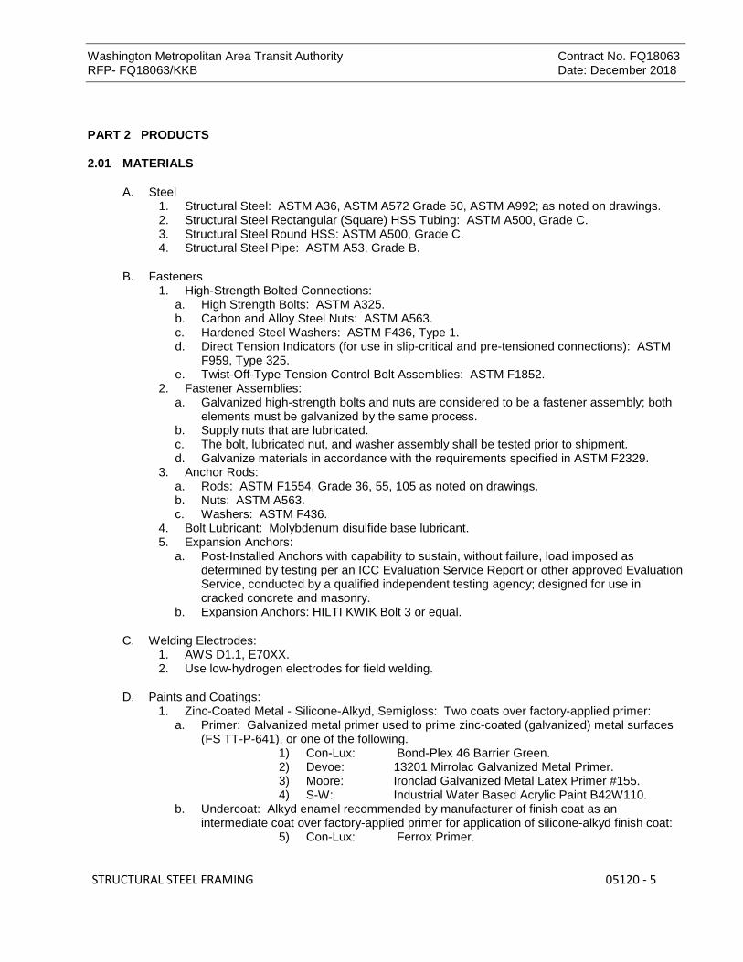
2.01 MATERIALS
A. Steel 1. Structural Steel: ASTM A36, ASTM A572 Grade 50, ASTM A992; as noted on drawings. 2. Structural Steel Rectangular (Square) HSS Tubing: ASTM A500, Grade C. 3. Structural Steel Round HSS: ASTM A500, Grade C. 4. Structural Steel Pipe: ASTM A53, Grade B.
B. Fasteners 1. High-Strength Bolted Connections:
a. High Strength Bolts: ASTM A325. b. Carbon and Alloy Steel Nuts: ASTM A563. c. Hardened Steel Washers: ASTM F436, Type 1. d. Direct Tension Indicators (for use in slip-critical and pre-tensioned connections): ASTM
F959, Type 325. e. Twist-Off-Type Tension Control Bolt Assemblies: ASTM F1852.
2. Fastener Assemblies: a. Galvanized high-strength bolts and nuts are considered to be a fastener assembly; both
elements must be galvanized by the same process. b. Supply nuts that are lubricated. c. The bolt, lubricated nut, and washer assembly shall be tested prior to shipment. d. Galvanize materials in accordance with the requirements specified in ASTM F2329.
3. Anchor Rods: a. Rods: ASTM F1554, Grade 36, 55, 105 as noted on drawings. b. Nuts: ASTM A563. c. Washers: ASTM F436.
4. Bolt Lubricant: Molybdenum disulfide base lubricant. 5. Expansion Anchors:
a. Post-Installed Anchors with capability to sustain, without failure, load imposed as determined by testing per an ICC Evaluation Service Report or other approved Evaluation Service, conducted by a qualified independent testing agency; designed for use in cracked concrete and masonry.
b. Expansion Anchors: HILTI KWIK Bolt 3 or equal.
C. Welding Electrodes: 1. AWS D1.1, E70XX. 2. Use low-hydrogen electrodes for field welding.
D. Paints and Coatings: 1. Zinc-Coated Metal - Silicone-Alkyd, Semigloss: Two coats over factory-applied primer:
a. Primer: Galvanized metal primer used to prime zinc-coated (galvanized) metal surfaces (FS TT-P-641), or one of the following.
1) Con-Lux: Bond-Plex 46 Barrier Green. 2) Devoe: 13201 Mirrolac Galvanized Metal Primer. 3) Moore: Ironclad Galvanized Metal Latex Primer #155. 4) S-W: Industrial Water Based Acrylic Paint B42W110.
b. Undercoat: Alkyd enamel recommended by manufacturer of finish coat as an intermediate coat over factory-applied primer for application of silicone-alkyd finish coat:
5) Con-Lux: Ferrox Primer.
STRUCTURAL STEEL FRAMING 05120 - 5
Washington Metropolitan Area Transit Authority Contract No. FQ18063 RFP- FQ18063/KKB Date: December 2018
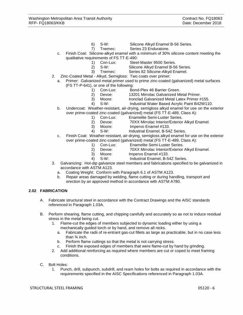
6) S-W: Silicone Alkyd Enamel B-56 Series. 7) Tnemec: Series 23 Enduratone.
c. Finish Coat: Silicone-alkyd enamel with a minimum of 30% silicone content meeting the qualitative requirements of FS TT-E-490:
1) Con-Lux: Steel-Master 9500 Series. 2) S-W: Silicone Alkyd Enamel B-56 Series. 3) Tnemec: Series 82 Silicone-Alkyd Enamel.
2. Zinc-Coated Metal - Alkyd, Semigloss: Two coats over primer: a. Primer: Galvanized metal primer used to prime zinc-coated (galvanized) metal surfaces
(FS TT-P-641), or one of the following: 1) Con-Lux: Bond-Plex 46 Barrier Green. 2) Devoe: 13201 Mirrolac Galvanized Metal Primer. 3) Moore: Ironclad Galvanized Metal Latex Primer #155. 4) S-W: Industrial Water Based Acrylic Paint B42W110.
b. Undercoat: Weather-resistant, air-drying, semigloss alkyd enamel for use on the exterior over prime-coated zinc-coated (galvanized) metal (FS TT-E-489, Class A):
1) Con-Lux: Enamelite Semi-Luster Series. 2) Devoe: 70XX Mirrolac Interior/Exterior Alkyd Enamel. 3) Moore: Impervo Enamel #133. 4) S-W: Industrial Enamel, B-54Z Series.
c. Finish Coat: Weather-resistant, air-drying, semigloss alkyd enamel for use on the exterior over prime-coated zinc-coated (galvanized) metal (FS TT-E-489, Class A):
1) Con-Lux: Enamelite Semi-Luster Series. 2) Devoe: 70XX Mirrolac Interior/Exterior Alkyd Enamel. 3) Moore: Impervo Enamel #133. 4) S-W: Industrial Enamel, B-54Z Series.
3. Galvanizing: Hot-dip galvanize steel members and fabrications specified to be galvanized in accordance with ASTM A123.
a. Coating Weight: Conform with Paragraph 6.1 of ASTM A123. b. Repair areas damaged by welding, flame cutting or during handling, transport and
erection by an approved method in accordance with ASTM A780.
2.02 FABRICATION
A. Fabricate structural steel in accordance with the Contract Drawings and the AISC standards referenced in Paragraph 1.03A.
B. Perform shearing, flame cutting, and chipping carefully and accurately so as not to induce residual stress in the metal being cut.
1. Flame-cut the edges of members subjected to dynamic loading either by using a mechanically guided torch or by hand, and remove all nicks.
a. Fabricate the radii of re-entrant gas-cut fillets as large as practicable, but in no case less than ¾ inch.
b. Perform flame cuttings so that the metal is not carrying stress. c. Finish the exposed edges of members that were flame-cut by hand by grinding.
2. Add additional reinforcing as required where members are cut or coped to meet framing conditions.
C. Bolt Holes: 1. Punch, drill, subpunch, subdrill, and ream holes for bolts as required in accordance with the
requirements specified in the AISC Specifications referenced in Paragraph 1.03A.
STRUCTURAL STEEL FRAMING 05120 - 6
Washington Metropolitan Area Transit Authority Contract No. FQ18063 RFP- FQ18063/KKB Date: December 2018
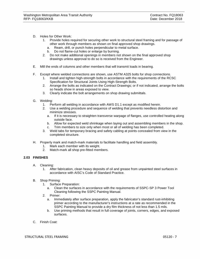
D. Holes for Other Work:
1. Provide holes required for securing other work to structural steel framing and for passage of other work through members as shown on final approved shop drawings.
a. Ream, drill, or punch holes perpendicular to metal surface. b. Do not flame-cut holes or enlarge by burning.
2. Do not make additional openings in members not shown on the final approved shop drawings unless approval to do so is received from the Engineer.
E. Mill the ends of columns and other members that will transmit loads in bearing.
F. Except where welded connections are shown, use ASTM A325 bolts for shop connections. 1. Install and tighten high-strength bolts in accordance with the requirements of the RCSC
Specification for Structural Joints Using High-Strength Bolts. 2. Arrange the bolts as indicated on the Contract Drawings; or if not indicated, arrange the bolts
so heads show in areas exposed to view. 3. Clearly indicate the bolt arrangements on shop drawing submittals.
G. Welding: 1. Perform all welding in accordance with AWS D1.1 except as modified herein. 2. Use a welding procedure and sequence of welding that prevents needless distortion and
minimize stresses. a. If it is necessary to straighten transverse warpage of flanges, use controlled heating along
outside face. b. Allow for expected weld shrinkage when laying out and assembling members in the shop. c. Trim members to size only when most or all of welding has been completed.
3. Weld tabs for temporary bracing and safety cabling at points concealed from view in the completed structure.
H. Properly mark and match-mark materials to facilitate handling and field assembly. 1. Mark each member with its weight. 2. Match-mark all shop pre-fitted members.
2.03 FINISHES
A. Cleaning: 1. After fabrication, clean heavy deposits of oil and grease from unpainted steel surfaces in
accordance with AISC’s Code of Standard Practice.
B. Shop Priming: 1. Surface Preparation:
a. Clean the surfaces in accordance with the requirements of SSPC-SP 3 Power Tool Cleaning following the SSPC Painting Manual.
2. Primer: a. Immediately after surface preparation, apply the fabricator’s standard rust-inhibiting
primer according to the manufacturer’s instructions at a rate as recommended in the SSPC Painting Manual to provide a dry film thickness of not less than 1.5 mils.
b. Use priming methods that result in full coverage of joints, corners, edges, and exposed surfaces.
C. Finish Coat:
STRUCTURAL STEEL FRAMING 05120 - 7
Washington Metropolitan Area Transit Authority Contract No. FQ18063 RFP- FQ18063/KKB Date: December 2018
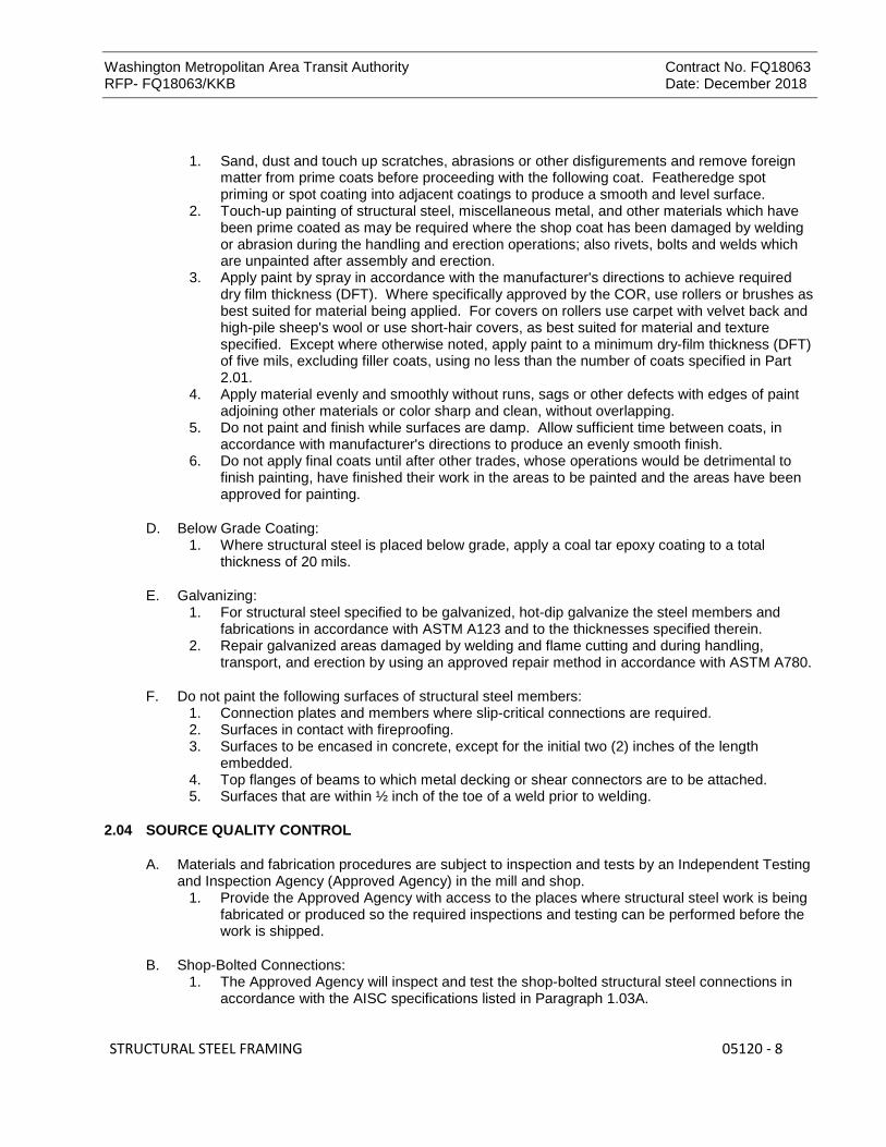
1. Sand, dust and touch up scratches, abrasions or other disfigurements and remove foreign
matter from prime coats before proceeding with the following coat. Featheredge spot priming or spot coating into adjacent coatings to produce a smooth and level surface.
2. Touch-up painting of structural steel, miscellaneous metal, and other materials which have been prime coated as may be required where the shop coat has been damaged by welding or abrasion during the handling and erection operations; also rivets, bolts and welds which are unpainted after assembly and erection.
3. Apply paint by spray in accordance with the manufacturer's directions to achieve required dry film thickness (DFT). Where specifically approved by the COR, use rollers or brushes as best suited for material being applied. For covers on rollers use carpet with velvet back and high-pile sheep's wool or use short-hair covers, as best suited for material and texture specified. Except where otherwise noted, apply paint to a minimum dry-film thickness (DFT) of five mils, excluding filler coats, using no less than the number of coats specified in Part 2.01.
4. Apply material evenly and smoothly without runs, sags or other defects with edges of paint adjoining other materials or color sharp and clean, without overlapping.
5. Do not paint and finish while surfaces are damp. Allow sufficient time between coats, in accordance with manufacturer's directions to produce an evenly smooth finish.
6. Do not apply final coats until after other trades, whose operations would be detrimental to finish painting, have finished their work in the areas to be painted and the areas have been approved for painting.
D. Below Grade Coating: 1. Where structural steel is placed below grade, apply a coal tar epoxy coating to a total
thickness of 20 mils.
E. Galvanizing: 1. For structural steel specified to be galvanized, hot-dip galvanize the steel members and
fabrications in accordance with ASTM A123 and to the thicknesses specified therein. 2. Repair galvanized areas damaged by welding and flame cutting and during handling,
transport, and erection by using an approved repair method in accordance with ASTM A780.
F. Do not paint the following surfaces of structural steel members: 1. Connection plates and members where slip-critical connections are required. 2. Surfaces in contact with fireproofing. 3. Surfaces to be encased in concrete, except for the initial two (2) inches of the length
embedded. 4. Top flanges of beams to which metal decking or shear connectors are to be attached. 5. Surfaces that are within ½ inch of the toe of a weld prior to welding.
2.04 SOURCE QUALITY CONTROL
A. Materials and fabrication procedures are subject to inspection and tests by an Independent Testing and Inspection Agency (Approved Agency) in the mill and shop.
1. Provide the Approved Agency with access to the places where structural steel work is being fabricated or produced so the required inspections and testing can be performed before the work is shipped.
B. Shop-Bolted Connections: 1. The Approved Agency will inspect and test the shop-bolted structural steel connections in
accordance with the AISC specifications listed in Paragraph 1.03A.
STRUCTURAL STEEL FRAMING 05120 - 8
Washington Metropolitan Area Transit Authority Contract No. FQ18063 RFP- FQ18063/KKB Date: December 2018
a. Verify proper fastening components were used and the connected elements were
fabricated properly. b. For slip-critical and pretension connections, test 2 bolts per connection.
2. Acceptance Criteria: a. Verify proper fastening component used. b. Verify proper fabrication of connected elements.
C. Shop Welding: 1. The Approved Agency will verify all welders and welding materials being supplied under this
Contract are properly certified and will conduct the inspections and tests specified. a. Inspect and test shop welds made during fabrication of structural steel assemblies by
performing a visual inspection of the full length of all welds and inspecting and testing shop-welded connections in accordance with the requirements of ASTM E164 and the following: 1) Ultrasonically inspect and test the entire length of all full penetration welds in
accordance with the requirements of ASTM E164. 2) Inspect the entire length of fillet welds in accordance with the requirements for the
Magnetic Particle Method specified in ASTM E709 and the following: a) For gusset plates welded to steel members, test 20 percent of fillet weld
locations. b) For all other fillet weld locations, test a minimum of 5 percent of the welds.
b. Record both the type and location of all defects found in the work, and record the work required and the work performed to correct deficiencies.
2. Acceptance Criteria: a. Verify weld materials, locations, and types agree with Construction Documents. b. Verify welds comply with AWS D1.1.
D. Submit mill test reports certifying the material provided conforms to the appropriate ASTM specification.
E. Promptly remove and replace materials or fabricated components that do not comply with specified requirements.
PART 3 EXECUTION
3.01 EXAMINATION
A. Before proceeding to erect the structural steel, verify the elevations of concrete and masonry bearing surfaces and locations of anchorages are in compliance with the Contract Documents and ready to receive the work of this Section.
B. Ensure anchor rods and other embedded items, that vary in location from the dimensions shown on the Contract Drawings, are positioned within the tolerances listed in the AISC Code of Standard Practice for Steel Buildings and Bridges.
C. Do not proceed with erection until unsatisfactory conditions have been corrected. 1. Immediately report errors in the structural steel, whether resulting from shop fabrication or
deformation resulting from handling or transportation, which will prevent the proper erection and fitting of parts.
STRUCTURAL STEEL FRAMING 05120 - 9
Washington Metropolitan Area Transit Authority Contract No. FQ18063 RFP- FQ18063/KKB Date: December 2018
3.02 ERECTION
A. Provide temporary shores, guys, braces, and other supports during erection to keep structural steel secure, plumb, and in alignment against temporary construction loads and loads equal in intensity to design loads.
1. Leave temporary bracing in place as long as required for safety.
B. Erect steel structures plumb in the location and at the elevations shown on the Contract Drawings and in accordance with the match marks, pertinent regulations, and the AISC standards referenced in Paragraph 1.03A.
1. Align column bases and bearing plates for beams and similar structural members using steel wedges or shims.
2. Do not field cut or alter structural members without the approval of the Engineer. 3. Allow concrete foundations to cure for a minimum of 14 days before tightening anchor rod
hardware. a. Do not tighten anchor rod hardware using impact torque wrenches.
4. Apply a coal tar epoxy coating to steel below grade.
C. Bolted Connections: 1. For connections using high-strength steel bolts, conform to requirements of the AISC
Specifications referenced in Paragraph 1.03A. a. Assemble high-strength bolted parts so they fit solidly together when assembled.
1) Remove scale, dirt, and other defects liable to prevent proper seating when joint surfaces are assembled, including joint surfaces adjacent to washers.
2) Do not use gaskets or any other interposed compressible materials. 3) Only use drift pins for bringing members into position, not to enlarge or distort holes.
2. Ensure holes are not enlarged and the metal in the vicinity of the holes is not disturbed by drifting during assembly.
a. Enlarge holes to admit bolts for connections only if approved by the Engineer. 1) Make the enlargement by reaming and not by burning. 2) Avoid hand reaming.
3. As erection progresses, install sufficient bolts in the work to resist dead loads, wind loads, and erection loads.
a. Arrange and insert the bolts so bolt heads show in areas exposed to view. b. Perform permanent bolting when sufficient alignment has been completed to ensure as
much of the structure as possible will be supported by such fastening work. 4. For bearing-type (snug-tightened) connections, tighten the ASTM A325 bolts to a snug tight
condition by either applying a few impacts from an impact wrench or the full effort of an ironworker using an ordinary spud wrench so all plies of the connected material have been brought into snug contact.
5. For slip-critical and pretension connections, tighten the ASTM A325 bolts, nuts, and direct tension indicators or twist-off-type tension control bolt in accordance with the AISC specifications listed in Paragraph 1.03A.
a. Clean oil, paint, or lacquer from the contact surfaces of slip-critical joints. b. Place direct tension indicators under either the bolt head or the hardened washer.
1) If direct tension indicators are placed under the turned element, place a hardened round steel washer between the direct tension indicator and the turned element.
c. To ensure proper tensioning of these connections is achieved, have a representative from the direct tension indicator supplier on site during their initial tightening to witness and approve of the degree of tightening.
STRUCTURAL STEEL FRAMING 05120 - 10
Washington Metropolitan Area Transit Authority Contract No. FQ18063 RFP- FQ18063/KKB Date: December 2018
D. Field Welding:
1. Provide only where approved by the Engineer or as indicated in the approved shop drawings.
a. Securely tighten erection bolts used in welded construction and leave them in place. b. Field welding rigid frame flange connection plates on columns may only be performed if
required for ease of erection and must be clearly indicated on the approved shop drawings and approved by the Engineer.
E. After the supported members have been aligned, properly positioned, and the anchor nuts have been tightened, dry-pack the entire area under bearing plates with non-shrink non-metallic grout.
1. Do not place concrete on steel structure until the grout is in place and anchor bolts have been tightened.
F. Prior to installing metal decking, clean all heavy rust, mill scale, dirt, or other material from the unpainted top flanges of supporting beams.
3.03 FIELD QUALITY CONTROL
A. An Independent Testing and Inspection Agency (Approved Agency) shall be engaged to inspect high-strength bolted connections and welded connections, to perform the specified tests, and interpret the test results; to confirm that the structure is square, plumb, and level in accordance with AISC tolerances; and to prepare and submit test reports for this work.
B. Field-Bolted Connections: 1. The Approved Agency will inspect and test the field-bolted structural steel connections in
accordance with the AISC specifications listed in Paragraph 1.03A and as specified. a. Verify proper fastening components were used and the connected elements were
fabricated properly. b. Slip-critical and pretension connections, test 2 bolts per connection.
2. Acceptance Criteria: a. Verify connections comply with the requirements specified in AISC and RCSC
specifications.
C. Field Welding: 1. The Approved Agency will verify all welders and welding materials in the field are properly
certified and will conduct the inspections and tests specified. a. Inspect and test field welds, in accordance with the requirements of AWS D1.1, made
during erection of structural steel assemblies by performing a visual inspection of the full length of all welds and the following: 1) Ultrasonically inspect and test the entire length of full penetration welds in
accordance with the requirements of ASTM E164: 2) Inspect the entire length of fillet welds in accordance with the requirements for the
Magnetic Particle Method specified in ASTM E709 and the following: a) For beam connection plates (angles) welded to plates embedded in concrete,
test all welds. b) For diagonal bracing members welded to gusset plates, test 40 percent of fillet
weld locations. c) For gusset plates welded to steel members, test 40 percent of fillet weld
locations. d) For all other fillet weld locations, test a minimum of 10 percent of the welds.
STRUCTURAL STEEL FRAMING 05120 - 11
Washington Metropolitan Area Transit Authority Contract No. FQ18063 RFP- FQ18063/KKB Date: December 2018
b. Record both the type and location of all defects found in the work, and record the work
required and the work performed to correct deficiencies. 2. Acceptance Criteria:
a. Verify welds comply with the requirements specified in AWS and ASTM specifications will be acceptable.
b. Verify welders and welding materials are properly certified.
D. Verification of Conditions 1. Have the Professional Land Surveyor survey each elevated framed level to determine the
top of steel elevations and the edge of slab locations, and verify that the structure is square, plumb, and level in accordance with AISC tolerances.
a. Submit a certified copy of the Professional Land Surveyor’s survey denoting top of steel elevations and the edge of slab locations for approval.
2. Verify only erectors qualified as specified herein erect the structural steel.
3.04 REPAIR/RESTORATION
A. Remove and replace work that does not comply with specified requirements. 1. Correct deficiencies in structural steel work that inspections and test reports have indicated
to be not in compliance with requirements. 2. Additional tests performed by the Approved Agency to reconfirm any noncompliant original
work and verify compliance of corrected work will be performed at no additional cost to the Owner.
B. Immediately after erection, clean field welds, bolted connections, and areas where shop paint is abraded; prime them with paint of the same quality as that used for the shop coat in accordance with the requirements specified in this Section.
1. Repair galvanized areas damaged by welding and flame cutting and during handling, transport, and erection by using an approved repair method in accordance with ASTM A780.
C. Apply touch-up paint to exposed areas using material as specified in Part 2.03.
D. Repair galvanized areas damaged by welding and flame cutting and during handling, transport, and erection by using an approved repair method in accordance with ASTM A780.
3.05 NON-CONFORMING WORK
A. Non-Conforming Work 1. Promptly remove and replace Work that does not comply with specified requirements.
a. Correct deficiencies in the Work that inspections and test reports have indicated to be not in compliance with requirements.
2. Record the work required and the work performed to correct deficiencies in field welding. 3. Depending on the amount of non-conforming work encountered, the amount of testing
required may be modified.
END OF SECTION
STRUCTURAL STEEL FRAMING 05120 - 12
Washington Metropolitan Area Transit Authority Contract No. FQ18063 RFP-FQ18063/KKB Date: December, 2018
SECTION 05310 METAL DECKING PART 1 - GENERAL 1.01 DESCRIPTION:
A. This section specifies providing metal roof decking.
B. Related Work Specified Elsewhere: 1. Touch up and field painting of metal deck: Section 09920.
1.02 QUALITY ASSURANCE:
A. Codes, Regulations, Reference Standards and Specifications: 1. Comply with codes and regulations of the jurisdictional authorities. 2. AISI Specifications for the Design of Light-Gauge Cold-Formed Steel
Structural Members. 3. AWS: D1.1. 4. SDI (Steel Deck Institute): Design Manual for Floor Decks and Roof
Decks. 5. ASTM: A653/A653M.
B. Qualification of Welding Personnel:
1. Employ welding personnel whose qualification is certified in accordance with AWS D1.1. Such certification is to remain in force for the duration of the welding operations under this Contract.
1.03 SUBMITTALS:
Submit the following for approval in accordance with the General Requirements and with the additional requirements as specified for each:
A. Shop Drawings:
1. nclude details of fabrication and erection including materials, dimensions, methods of joining, welding, accessories, fastenings and openings through decking.
1X0000 (08/01) 05310 - 1
Washington Metropolitan Area Transit Authority Contract No. FQ18063 RFP-FQ18063/KKB Date: December, 2017
B. Samples:
1. Three of each type of the following products used in the work. a. Decking: Six inches by width of material. b. Accessories. c. Fasteners.
C. Certification:
1. Certification that welding personnel have been qualified in accordance with AWS D1.1.
1.04 PRODUCT DELIVERY, STORAGE AND HANDLING:
A. Deliver products in good condition.
B. Store products so as to preclude corrosion, deterioration and damage.
C. Handle products so as to prevent damage. 1.05 JOB CONDITIONS:
D. Do not apply construction loads, such as roofing materials and aggregate, in excess of the live loads for which the deck is designed.
PART 2 - PRODUCTS 2.01 MATERIALS:
A. Steel Decking: 1. Galvanized: ASTM A653/A653M, Coating G60 or G90, gauge as shown. 2. Where terne-coated stainless steel is to be installed over decking, fabricate
decking with clear space between ribs 1/2-inch wide maximum.
B. Accessories: 1. Types shown or necessary to complete installation, such as 14-gauge
recessed sump pans for roof drains, cover plates where panels abut or change direction and closure plates.
2. Same gauge and finish as decking, unless otherwise shown or specified.
C. Fasteners: As shown on approved shop drawings. 2.02 FABRICATION:
Washington Metropolitan Area Transit Authority Contract No. FQ18063 RFP-FQ18063/KKB Date: December, 2018
A. Deck units countersunk at ends to form smooth, flush top surface at overlapping
ends, except for 12-gauge and 14-gauge material.
B. Deck units having interlocking side laps, in standard width and longest practicable lengths
C. Steel Roof Deck: Gage and depth as shown.
D. Metal Forming (corrugated):
1. Maximum Flexural Working Stress: 33,000 psi. 2. Maximum Roof Deflection: 1/240 of span, c/c of supports, under live load. 3. Maximum Floor Deflection: 1/360 of span, c/c of supports, under live load.
PART 3 - EXECUTION 3.01 INSTALLATION:
A. Erect steel decking and accessories in accordance with approved shop drawings and manufacturer's recommendations.
B. Place decking units on the supporting steel, align and adjust to final position before
permanently fastening.
C. If supporting beams are not in proper alignment or at correct elevation to provide bearing and alignment of deck units; do not place decking units in deficient areas until necessary corrections have been made.
D. Continue decking over three or more spans.
E. Perform welding in accordance with AWS D1.1. F. Use electric-arc welding to weld deck panels to end supports as shown on the
Contract Drawings or on approved shop drawings. Where panel ends meet, provide minimum two-inch overlap and weld to fuse ends of units together.
G. Crimp side joints of adjacent panels and weld at intervals not exceeding three feet.
H. Remove burrs and sharp edges.
1X0000 (08/01) 05310 - 3 05310 - 3 1X0000 (08/01)
Washington Metropolitan Area Transit Authority Contract No. FQ18063 RFP-FQ18063/KKB Date: December, 2017
I. Where welding occurs through deck, use welding washers and plug welds to ensure
proper attachment.
J. Cut bevels and perform other special cutting and fitting at jobsite.
K. Provide necessary support framing and reinforcement and openings for items penetrating deck panels.
L. Coordinate cutting of openings for work of other trades with trades involved.
M. Do not hang mechanical equipment or other loads from steel deck.
N. Repair areas where galvanizing has been damaged by welding or cutting operations
using cold galvanizing compound acceptable to the Engineer.
O. Clean galvanized roof sheets with zinc oxide residue or evidence of rusting with solvent and apply zinc-rich paint to restore corrosion resistance.
3.02 CLEAN-UP:
A. Clean up rubbish and debris caused by this work and remove from site.
B. Leave decks and areas surrounding work in broom-clean condition. END OF SECTION
05310 - 4 1X0000 (08/01)
Washington Metropolitan Area Transit Authority Contract No. FQ18063 RFP- FQ18063/KKB__ Date: December 2018
SECTION 06100
ROUGH CARPENTRY
PART 1: GENERAL
1.01 DESCRIPTION
A. This section includes the following:
1. Concealed wood blocking nailers and supports
2. Preservative treated wood materials
1.02 RELATED SECTIONS
A. Section 07532 – EPDM Membrane Roofing
C. Section 07620 – Flashing and Sheet Metal
1.03 REFERENCE STANDARDS
A. ASTM A153/A153M - Standard Specification for Zinc Coating (Hot-Dip) on Iron and Steel Hardware; 2009.
B. AWPA U1 - Use Category System: User Specification for Treated Wood; American Wood Protection Association; 2012.
C. PS 20 - American Softwood Lumber Standard; National Institute of Standards and Technology, Department of Commerce; 2010.
D. SPIB (GR) - Grading Rules; Southern Pine Inspection Bureau, Inc.; 2002.
1.04 SUBMITTALS
A. Product Data: Provide deck profile characteristics, dimensions, structural properties, and finishes.
B. Certificates: Certify that products furnished meet or exceed specified requirements.
ROUGH CARPENTRY 06100 - 1
Washington Metropolitan Area Transit Authority Contract No. FQ18063 RFP- FQ18063/KKB__ Date: December 2018
1.05 DELIVERY, STORAGE, AND HANDLING
A. General: Cover wood products to protect against moisture. Support stacked products to prevent deformation and to allow air circulation.
1.06 WARRANTY
A. Correct defective Work within a one year period after Date of Substantial Completion.
PART 2: PRODUCTS
2.01 GENERAL REQUIREMENTS
A. Dimension Lumber: Comply with PS 20 and requirements of specified grading agencies.
1. Provide any species graded by the agency specified; if no grading agency is specified, provide lumber graded by any grading agency meeting the specified requirements.
2. Grading Agency: Any grading agency whose rules are approved by the Board of Review, American Lumber Standard Committee (www.alsc.org) and who provides grading service for the species and grade specified; provide lumber stamped with grade mark unless otherwise indicated.
B. Lumber fabricated from old growth timber is not permitted.
2.02 DIMENSION LUMBER FOR CONCEALED APPLICATIONS
A. Grading Agency: Southern Pine Inspection Bureau, Inc. (SPIB).
B. Sizes: Nominal sizes as indicated on drawings or match existing, S4S.
C. Moisture Content: S-dry or MC19.
D. Miscellaneous Framing, Blocking, Nailers, Grounds, and Furring:
1. Lumber: S4S, No. 2 or Standard Grade.
2. Boards: Standard or No. 3.
2.03 ACCESSORIES
A. Fasteners and Anchors:
ROUGH CARPENTRY 06100 - 2
Washington Metropolitan Area Transit Authority Contract No. FQ18063 RFP- FQ18063/KKB__ Date: December 2018
1. Metal and Finish: Hot-dipped galvanized steel per ASTM A 153/A 153M for high humidity and
preservative-treated wood locations, unfinished steel elsewhere.
2. Drywall Screws: Bugle head, hardened steel, power driven type, length three times thickness of sheathing.
3. Anchors: Expansion shield and lag bolt type for anchorage to solid masonry or concrete.
2.05 FACTORY WOOD TREATMENT
A. Treated Lumber and Plywood: Comply with requirements of AWPA U1 - Use Category System for wood treatments determined by use categories, expected service conditions, and specific applications.
1. Preservative-Treated Wood: Provide lumber and plywood marked or stamped by an ALSC-accredited testing agency, certifying level and type of treatment in accordance with AWPA standards.
B. Preservative Treatment:
1. Manufacturers:
a. Arch Wood Protection, Inc: www.wolmanizedwood.com.
b. Viance, LLC: www.treatedwood.com.
c. Osmose, Inc: www.osmose.com.
d. Substitutions: See Section 01600 - Product Requirements.
2. Preservative Pressure Treatment of Lumber Above Grade: AWPA U1, Use Category UC3B, Commodity Specification A using waterborne preservative to 0.25 lb/cu ft retention.
a. Kiln dry lumber after treatment to maximum moisture content of 19 percent.
b. Treat lumber in contact with roofing, flashing, or waterproofing.
c. Treat lumber in contact with masonry or concrete.
PART 3: EXECUTION
3.01 PREPARATION
A. Coordinate installation of rough carpentry members specified in other sections.
3.02 INSTALLATION - GENERAL
A. Select material sizes to minimize waste.
ROUGH CARPENTRY 06100 - 3
Washington Metropolitan Area Transit Authority Contract No. FQ18063 RFP- FQ18063/KKB__ Date: December 2018
B. Reuse scrap to the greatest extent possible; clearly separate scrap for use on site as accessory
components, including: shims, bracing, and blocking.
3.03 BLOCKING, NAILERS, AND SUPPORTS
A. Provide framing and blocking members as indicated or as required to support finishes, fixtures, specialty items, and trim.
3.05 ROOF-RELATED CARPENTRY
A. Coordinate installation of roofing carpentry with framing of roof openings, and roofing assembly installation.
3.06 SITE APPLIED WOOD TREATMENT
A. Apply preservative treatment compatible with factory applied treatment at site-sawn cuts, complying with manufacturer's instructions.
B. Allow preservative to dry prior to erecting members.
3.07 TOLERANCES
A. Framing Members: 1/4 inch from true position, maximum.
B. Variation from Plane (Other than Floors): 1/4 inch in 10 feet maximum, and 1/4 inch in 30 feet maximum.
3.08 CLEANING
A. Do not leave any wood, shavings, sawdust, etc. on the ground or buried in fill.
B. Prevent sawdust and wood shavings from entering the storm drainage system.
END OF SECTION
ROUGH CARPENTRY 06100 - 4
Washington Metropolitan Area Transit Authority Contract No. FQ18063 RFP- FQ18063/KKB Date: December 2018
SECTION 07212
BOARD INSULATION
PART 1 GENERAL
1.01 SECTION INCLUDES
A. Board insulation at over roof deck.
1.02 RELATED REQUIREMENTS
A. Section 06100 - Rough Carpentry
1.03 REFERENCE STANDARDS
A. ASTM C578 - Standard Specification for Rigid, Cellular Polystyrene Thermal Insulation; 2014.
B. ASTM C1289 - Standard Specification for Faced Rigid Cellular Polyisocyanurate Thermal Insulation Board; 2014.
C. ASTM E84 - Standard Test Method for Surface Burning Characteristics of Building Materials; 2014.
D. ASTM E96/E96M - Standard Test Methods for Water Vapor Transmission of Materials; 2014.
1.04 SUBMITTALS
A. Product Data: Provide data on product characteristics, performance criteria, and product limitations.
B. Manufacturer's Certificate: Certify that products meet or exceed specified requirements.
C. Manufacturer's Installation Instructions: Include information on special environmental conditions required for installation and installation techniques.
D. Provide certification from the manufacturer that wind uplift requirements are being met per Building Code through the use of adhesives and fasteners. Submit all pertinent data.
E. Manufacturer shall provide complete shop drawings indicating board layout and thickness to achieve slopes as indicated on drawings.
1.05 FIELD CONDITIONS
A. Do not install insulation adhesives when temperature or weather conditions are detrimental to successful installation.
BOARD INSULATION 07212 - 1
Washington Metropolitan Area Transit Authority Contract No. FQ18063 RFP- FQ18063/KKB Date: December 2018
PART 2 PRODUCTS
2.01 APPLICATIONS
A. Insulation Over Roof Deck: Rigid foam board. See drawings.
2.02 FOAM BOARD INSULATION MATERIALS
A. Polyisocyanurate Board Insulation with Fiberglass Mat Facer: Rigid cellular foam, complying with ASTM C1289; Type I, fiberglass mat fiber facing top side; Class 1, non-reinforced foam core. 1. Flame Spread Index: 25 or less, when tested in accordance with ASTM E84. 2. Smoke Developed Index: 450 or less, when tested in accordance with ASTM
E84. 3. Compressive Strength: 25 psi 4. Board Size: as recommended by manufacturer. 5. Board Thickness: as required. See plans. 6. Thermal Resistance: R-value of 25. 7. Board Edges: Square. 8. Manufacturers:
a. Manufacturer of roof membrane. b. Manufacturer approved by manufacturer of roof membrane.
2.03 ACCESSORIES
A. Tape: As recommended by manufacturer.
B. Tape joints of rigid insulation in accordance with roofing and insulation manufacturers' instructions.
C. Insulation Fasteners: Appropriate for purpose intended and approved by roofing manufacturer. 1. Length as required for thickness of insulation material and penetration of deck
substrate, with metal washers.
D. Wire Mesh: Galvanized steel, hexagonal wire mesh.
E. Adhesive: Type recommended by insulation manufacturer for application.
PART 3 EXECUTION
3.01 EXAMINATION
A. Verify that substrate, adjacent materials, and insulation materials are dry and that substrates are ready to receive insulation and adhesive.
B. Verify substrate surfaces are flat, free of honeycomb, fins, irregularities, or materials or substances that may impede adhesive bond.
3.02 PREPARATION:
BOARD INSULATION 07212 - 2
Washington Metropolitan Area Transit Authority Contract No. FQ18063 RFP- FQ18063/KKB Date: December 2018
A. Prepare surfaces smooth, dry, clean, and free of projections, oil, grease, wax, rough mortar, debris and other substances that might prevent proper application of insulation.
B. Allow decks to dry thoroughly before application of insulation. Test for dampness per manufacturer’s recommendations.
3.03 APPLICATION OF ROOF INSULATION:
A. General Requirements for Application: 1. Apply insulation in direct contact with roof deck. Keep roof-insulation materials
dry before, during and after application. Apply insulation to deck so that continuous longitudinal joints are parallel to short dimension of roof; stagger cross joints by starting alternate courses with half-size insulation boards. Keep insulation 1/2-inch clear of vertical surfaces.
2. Install insulation in a minimum of 2 layers. Stagger the joints of each succeeding layer in both directions with respect to layer below. Embed succeeding layers firmly in insulation adhesive.
B. Application on Steel Decks: 1. Apply insulation so that joints occur on solid bearing surfaces only rather than over
open ribs. Apply insulation of the indicated thickness and as required to achieve the roof slopes indicated.
2. Before insulation is installed, uniformly apply adhesive at high sections of steel deck with adhesive primer at the rate recommended by the manufacturer. Allow primer to dry.
3. Apply adhesive to high sections of deck at the rate recommended by the manufacturer. Do not permit adhesive to flow into ribs or flutes of decking.
4. Place insulation while adhesive is still workable. When multiple layers of insulation are used, install second layer and succeeding layers as specified under general requirements for application.
C. Protection: 1. Do not install any insulation that cannot be roofed over in a day. 2. Protect open ends of each day's work with temporary water cut-offs; remove cut-
offs when work is resumed. 3. Protect open spaces between insulation and parapets or other walls and spaces
at curbs, hatches, expansion joints and similar locations until permanent roofing and flashing is applied. Storing, walking, wheeling or trucking directly on insulation or on roofed surfaces is prohibited; provide smooth, clean board or plank walkways, runways and platforms as necessary.
4. Limit storage loads on platforms and wheeling loads to 40 psf uniformly distributed. Limit size and weight of mechanical equipment used for insulation work so that deflection of roof deck under its use does not exceed 1/240 of deck span.
END OF SECTION
BOARD INSULATION 07212 - 3
Washington Metropolitan Area Transit Authority Contract No. FQ18063 RFP- FQ18063/KKB Date: December 2018
PAGE INTENTIONALLY LEFT BLANK
BOARD INSULATION 07212 - 4
Washington Metropolitan Area Transit Authority Contract No. FQ18063 RFP- FQ18063/KKB Date: December 2018
SECTION 07532
ETHYLENE-PROPYLENE-DIENE-MONOMER ROOFING (EPDM)
PART 1 GENERAL
1.01 SECTION INCLUDES
A. EPDM membrane roofing system, including all components specified.
B. Disposal of demolition debris and construction waste is the responsibility of Contractor. Perform disposal in manner complying with all applicable federal, state, and local regulations.
C. Comply with the published recommendations and instructions of the roofing membrane manufacturer.
1.02 RELATED REQUIREMENTS
A. Section 06100 - Rough Carpentry: Wood nailers associated with roofing and roof insulation.
B. Section 07595 - Preparation for Re-Roofing.
C. Section 07620 - Sheet Metal Flashing and Trim: Formed metal flashing and trim items associated with roofing.
D. Section 07710 – Manufactured Roof Specialties: Manufactured copings, fascias, gravel stops, and other flashing-related items.
E. Section 15010 - Mechanical Provisions, Materials and Methods.
1.03 DEFINITIONS
A. Roofing Terminology: Refer to ASTM D1079 for definition of terms related to roofing work not otherwise defined in the section.
1.04 REFERENCE STANDARDS
A. ASTM C1177/C1177M - Standard Specification for Glass Mat Gypsum Substrate for Use as Sheathing; 2013.
B. ASTM C1289 - Standard Specification for Faced Rigid Cellular Polyisocyanurate Thermal Insulation Board; 2014.
C. ASTM D1079 - Standard Terminology Relating to Roofing, Waterproofing, and Bituminous Materials; 2013.
D. ASTM D3273 - Standard Test Method for Resistance to Growth of Mold on the Surface of Interior Coatings in an Environmental Chamber; 2012.
E. ASTM E84 - Standard Test Method for Surface Burning Characteristics of Building Materials; 2014.
ETHYLENE-PROPYLENE-DIENE-MONOMER ROOFING (EPDM) 07532 - 1
Washington Metropolitan Area Transit Authority Contract No. FQ18063 RFP- FQ18063/KKB Date: December 2018
F. ASTM E136 - Standard Test Method for Behavior of Materials in a Vertical Tube Furnace At 750 Degrees C; 2012.
G. CAN-ULC-S770 - Standard Test Method Determination of L-Term Thermal Resistance Of Closed-Cell Thermal Insulating Foams; 2009.
1.05 SUBMITTALS
A. Product Data: 1. Provide membrane manufacturer's printed data sufficient to show that all components
of roofing system, including insulation and fasteners, comply with the specified requirements and with the membrane manufacturer's requirements and recommendations for the system type specified; include data for each product used in conjunction with roofing membrane.
B. Samples: Submit samples of each product to be used.
C. Shop Drawings: Provide: 1. The roof membrane manufacturer's standard details customized for this project for all
relevant conditions, including flashings, base tie-ins, roof edges, terminations, expansion joints, penetrations, and drains.
2. For tapered insulation, provide project-specific layout and dimensions for each board.
D. Specimen Warranty: Submit prior to starting work.
E. Installer Qualifications: Letter from manufacturer attesting that the roofing installer meets the specified qualifications.
F. Pre-Installation Notice: Copy to show that manufacturer's required Pre Installation Notice (PIN) has been accepted and approved by the manufacturer.
G. Executed Warranty.
H. Inspection Report for Information: Copy of roofing system manufacturer's inspection report of completed roofing membrane.
1.06 DELIVERY, STORAGE AND HANDLING
A. Deliver products in manufacturer's original containers, dry and undamaged, with seals and labels intact and legible.
B. Store materials clear of ground and moisture with weather protective covering.
C. Place and store roofing materials and equipment in a manner to avoid damage to deck or structural supporting members.
D. Protect roofing insulation materials from damage and from deterioration by sunlight, moisture, soiling, and other sources. Store in a dry location.
E. Keep combustible materials away from ignition sources.
ETHYLENE-PROPYLENE-DIENE-MONOMER ROOFING (EPDM) 07532 - 2
Washington Metropolitan Area Transit Authority Contract No. FQ18063 RFP- FQ18063/KKB Date: December 2018
1.07 WARRANTY
A. Comply with all warranty procedures required by manufacturer, including notifications, scheduling, and inspections.
B. Commencement of work by Contractor shall constitute acknowledgement by Contractor that this specification can be satisfactorily executed, under the project conditions and with all necessary prerequisites for warranty acceptance by roofing membrane manufacturer. No modification of the Contract Sum will be made for failure to adequately examine the Contract Documents or the project conditions.
C. Warranty: Provide warranty covering membrane, roof insulation, and other indicated components of the system, for the term indicated. 1. Limit of Liability: 20 Years from the Date of Substantial Completion, no dollar
limitation. 2. Scope of Coverage: Repair leaks in the roofing system caused by:
a. Ordinary wear and tear of the elements. b. Manufacturing defect in materials. c. Defective workmanship used to install these materials. d. Damage due to winds up to 55 mph (88 km/h).
PART 2 PRODUCTS
2.01 MANUFACTURERS
Basis of Design: Firestone Building Products LLC, Carmel, IN; EcoWhite Platinum EPDM: www.firestonebpco.com.
B. Or approved equal.
C. Manufacturer of Insulation and Cover Boards: Same manufacturer as roof membrane.
2.02 ROOFING SYSTEM DESCRIPTION
A. Roofing System: Ethylene-propylene-diene-monomer (EPDM) single-ply membrane. 1. Membrane Attachment: Fully adhered. 2. Warranty: Full system warranty; 20 Year No Dollar Limit Warranty from the Date of
Substantial Completion covering membrane, roof insulation, and membrane accessories.
3. Comply with applicable local building code requirements. 4. Provide assembly having Underwriters Laboratories, Inc. (UL) Class A Fire Hazard
Classification.
B. Roofing System Components: Listed in order from the top of the roof down: 1. Membrane: Thickness as specified. 2. Deck Cover Board: Gypsum-based board, 1/4 inch (6 mm) thick; loose-laid, no
attachment. 3. Insulation: See specification section 07212.
ETHYLENE-PROPYLENE-DIENE-MONOMER ROOFING (EPDM) 07532 - 3
Washington Metropolitan Area Transit Authority Contract No. FQ18063 RFP- FQ18063/KKB Date: December 2018
2.03 EPDM MEMBRANE MATERIALS
A. Roofing and Flashing Membrane: Cured synthetic single-ply membrane composed of ethylene propylene diene monomer (EPDM) with the following properties: 1. Thickness: 0.090 inch. 2. Nominal Thickness Tolerance: Plus/minus 10 percent. 3. Sheet Width: Provide the widest available sheets to minimize field seaming. 4. Cool Roof Surface: Provide white reflective roof surface, SRI-78.
B. Membrane Fasteners: Type and size as required by roof membrane manufacturer for roofing system and warranty to be provided; use only fasteners furnished by roof membrane manufacturer.
C. Flashing Membrane: Self-curing, non-reinforced membrane composed of non-vulcanized EPDM rubber, complying with ASTM D4811 Type II, and with the following properties: 1. Thickness: 0.055 inch. 2. Provide Cool Roof Surface: Provide white reflective roof surface, SRI-78
D. Pre-Molded Pipe Flashings: EPDM, molded for quick adaptation to different sized pipes; EPDM Pipe Flashing.
E. Self-Adhesive Lap Splice Tape: 35 mil EPDM-based, formulated for compatibility with EPDM membrane and high-solids primer; Splice tape.
F. Splice Adhesive: Synthetic polymer-based, formulated for compatibility with EPDM membrane and metal surfaces; SA-1065 Splice Adhesive.
G. Adhesive Primer: Synthetic rubber based primer formulated for compatibility with EPDM membrane and tape adhesive, with VOC content less than 2.1 lb/gal.
H. Seam Edge Treatment: EPDM rubber-based sealant, formulated for sealing exposed edges of membrane at seams; Lap sealant.
I. Pourable Sealer: Two-part polyurethane, two-color for reliable mixing.
J. Water Block Seal: Butyl rubber sealant for use between two surfaces, not exposed.
K. Metal Plates and Strips Used for Fastening Membrane and Insulation: Steel with Galvalume coating; corrosion-resistance meeting FM 4470 criteria.
L. Termination Bars: Aluminum bars with integral caulk ledge; 1.3 inches wide by 0.10 inch thick.
M. Roof Walkway Pads: EPDM, 0.30 inch thick by 30 by 30 inches with EPDM tape adhesive strips laminated to the bottom.
PART 3 INSTALLATION
3.01 GENERAL INSTALLATION REQUIREMENTS
A. Install roofing, insulation, flashings, and accessories in accordance with roofing manufacturer's published instructions and recommendations for the specified roofing system. Where
ETHYLENE-PROPYLENE-DIENE-MONOMER ROOFING (EPDM) 07532 - 4
Washington Metropolitan Area Transit Authority Contract No. FQ18063 RFP- FQ18063/KKB Date: December 2018
manufacturer provides no instructions or recommendations, follow NRCA Recommendations and industry standards. Comply with federal, state, and local regulations.
B. Obtain all relevant instructions and maintain copies at project site for duration of installation period.
C. Do not start work until Pre-Installation Notice has been submitted to manufacturer as notification that this project requires a manufacturer's warranty.
D. Perform work using competent and properly equipped personnel.
E. Temporary closures, which ensure that moisture does not damage any completed section of the new roofing system, are the responsibility of the applicator. Completion of flashings, terminations, and temporary closures shall be completed as required to provide a watertight condition.
F. Install roofing membrane only when surfaces are clean, dry, smooth and free of snow or ice; do not apply roofing membrane during inclement weather or when ambient conditions will not allow proper application; consult manufacturer for recommended procedures during cold weather. Do not work with sealants and adhesives when material temperature is outside the range of 60 to 80 degrees F (15 to 25 degrees C).
G. Protect adjacent construction, property, vehicles, and persons from damage related to roofing work; repair or restore damage caused by roofing work. 1. Protect from spills and overspray from bitumen, adhesives, sealants and coatings. 2. Particularly protect metal, glass, plastic, and painted surfaces from bitumen,
adhesives, and sealants within the range of wind-borne overspray. 3. Protect finished areas of the roofing system from roofing related work traffic and traffic
by other trades.
H. Until ready for use, keep materials in their original containers as labeled by the manufacturer.
I. Consult membrane manufacturer's instructions, container labels, and Material Safety Data Sheets (MSDS) for specific safety instructions. Keep all adhesives, sealants, primers and cleaning materials away from all sources of ignition.
3.02 EXAMINATION
A. Examine roof deck to determine that it is sufficiently rigid to support installers and their mechanical equipment and that deflection will not strain or rupture roof components or deform deck.
B. Verify that surfaces and site conditions are ready to receive work. Correct defects in the substrate before commencing with roofing work.
C. Examine roof substrate to verify that it is properly sloped to drains.
D. Verify that the specifications and drawing details are workable and not in conflict with the roofing manufacturer's recommendations and instructions; start of work constitutes acceptance of project conditions and requirements.
ETHYLENE-PROPYLENE-DIENE-MONOMER ROOFING (EPDM) 07532 - 5
Washington Metropolitan Area Transit Authority Contract No. FQ18063 RFP- FQ18063/KKB Date: December 2018
3.03 PREPARATION
A. Remove all of the existing EPDM roof system down to the roof deck. Dispose of all materials properly. Perform asbestos removal in accordance with federal, state and local regulations and dispose of waste in legal manner. 1. At penetrations, remove all existing flashings, including lead, asphalt, mastic, etc. 2. At walls, curbs, and other vertical and sloped surfaces, remove loose and unsecured
flashings;
B. Take appropriate measures to ensure that fumes from adhesive solvents are not drawn into the building through air intakes.
C. Prior to proceeding, prepare roof surface so that it is clean, dry, and smooth, and free of sharp edges, fins, roughened surfaces, loose or foreign materials, oil, grease and other materials that may damage the membrane.
D. Fill all surface voids in the immediate substrate that are greater than 1/4 inch (6 mm) wide with fill material acceptable insulation to membrane manufacturer.
E. Protect roof drains and other deck penetrations to prevent spillage and migration of roofing fluids.
3.04 SINGLE-PLY MEMBRANE INSTALLATION
A. Beginning at low point of roof, place membrane without stretching over substrate and allow to relax at least 30 minutes before attachment or splicing; in colder weather allow for longer relax time.
B. Lay out the membrane pieces so that field and flashing splices are installed to shed water.
C. Install membrane without wrinkles and without gaps or fishmouths in seams; bond and test seams and laps in accordance with membrane manufacturer's instructions and details.
D. Install membrane adhered to the substrate, with edge securement as specified.
E. Adhered Membrane: Bond membrane sheet to substrate using membrane manufacturer's recommended bonding material, application rate, and procedures.
F. Edge Securement: Secure membrane at all locations where membrane terminates or goes through an angle change greater than 2 in 12 inches (1:6 ) using mechanically fastened reinforced perimeter fastening strips, plates, or metal edging as indicated or as recommended by roofing manufacturer. 1. Exceptions: Round pipe penetrations less than 18 inches in diameter and square
penetrations less than 4 inches square. 2. Metal edging is not merely decorative; ensure anchorage of membrane as intended by
roofing manufacturer.
G. Correct deficiencies in or remove roofing membrane that does not comply with requirements, repair substrates, reapply roofing membrane, and repair flashing sheets.
ETHYLENE-PROPYLENE-DIENE-MONOMER ROOFING (EPDM) 07532 - 6
Washington Metropolitan Area Transit Authority Contract No. FQ18063 RFP- FQ18063/KKB Date: December 2018
3.05 FLASHING AND ACCESSORIES INSTALLATION
A. Install flashings, including laps, splices, joints, bonding, adhesion, and attachment, as required by membrane manufacturer's recommendations and details.
B. Metal Accessories: Install metal edgings, gravel stops, and copings in locations indicated on the drawings, with horizontal leg of edge member over membrane and flashing over metal onto membrane. 1. Follow roofing manufacturer's instructions. 2. Remove protective plastic surface film immediately before installation. 3. Install water block sealant under the membrane anchorage leg. 4. Flash with manufacturer's recommended flashing sheet unless otherwise indicated. 5. Where single application of flashing will not completely cover the metal flange, install
additional piece of flashing to cover the metal edge. 6. If the roof edge includes a gravel stop and sealant is not applied between the laps in
the metal edging, install an additional piece of self-adhesive flashing membrane over the metal lap to the top of the gravel stop; apply seam edge treatment at the intersections of the two flashing sections.
7. When the roof slope is greater than 1:12, apply seam edge treatment along the back edge of the flashing.
C. Existing Scuppers: Remove scupper and install new scupper.
D. Scuppers: Set in sealant and secure to structure; flash as recommended by manufacturer.
E. Roofing Relief Joints: Install as shown on drawings and as recommended by roofing manufacturer.
F. Flashing at Walls, Curbs, and Other Vertical and Sloped Surfaces: Install weathertight flashing at all walls, curbs, parapets, curbs, skylights, and other vertical and sloped surfaces that the roofing membrane abuts to; extend flashing at least 8 inches (200 mm) high above membrane surface. 1. Use the longest practical flashing pieces. 2. Evaluate the substrate and overlay and adjust installation procedure in accordance
with membrane manufacturer's recommendations. 3. Complete the splice between flashing and the main roof sheet with specified splice
adhesive before adhering flashing to the vertical surface. 4. Provide termination directly to the vertical substrate as shown on roof drawings.
G. Roof Drains: 1. Existing Drains: Remove all existing flashings, drain leads, roofing materials and
cement from the drain; remove clamping ring. 2. Taper insulation around drain to provide smooth transition from roof surface to drain.
Use specified pre-manufactured tapered insulation with facer or suitable bonding surface to achieve slope; slope not to exceed manufacturer's recommendations.
3. Position membrane, then cut a hole for roof drain to allow 1/2 to 3/4 inch (12 to 19 mm) of membrane to extend inside clamping ring past drain bolts.
4. Make round holes in membrane to align with clamping bolts; do not cut membrane back to bolt holes.
5. Apply sealant on top of drain bowl where clamping ring seats below the membrane
ETHYLENE-PROPYLENE-DIENE-MONOMER ROOFING (EPDM) 07532 - 7
Washington Metropolitan Area Transit Authority Contract No. FQ18063 RFP- FQ18063/KKB Date: December 2018
6. Install roof drain clamping ring and clamping bolts; tighten clamping bolts to achieve constant compression.
H. Flashing at Penetrations: Flash all penetrations passing through the membrane; make flashing seals directly to the penetration. 1. Pipes, Round Supports, and Similar Items: Flash with specified pre-molded pipe
flashings wherever practical; otherwise use specified self-curing elastomeric flashing. 2. Pipe Clusters and Unusual Shaped Penetrations: Provide penetration pocket at least 2
inches (50 mm) deep, with at least 1 inch (25 mm) clearance from penetration, sloped to shed water.
3. Structural Steel Tubing: If corner radii are greater than 1/4 inch (6 mm) and longest side of tube does not exceed 12 inches (305 mm), flash as for pipes; otherwise, provide a standard curb with flashing.
4. Flexible and Moving Penetrations: Provide weather-tight gooseneck set in sealant and secured to deck, flashed as recommended by manufacturer.
5. High Temperature Surfaces: Where the in-service temperature is, or is expected to be, in excess of 180 degrees F (82 degrees C), protect the elastomeric components from direct contact with the hot surfaces using an intermediate insulated sleeve as flashing substrate as recommended by membrane manufacturer.
3.06 FINISHING AND WALKWAY INSTALLATION
A. Install walkways at access points to the roof, around all rooftop equipment. Provide a continuous path of walkway pads connecting all equipment from roof access points, in a logical manner so as not to waste material. 1. Use specified walkway pads unless otherwise indicated. 2. Do not install walkway pads within 10 feet of any roof edge.
B. Walkway Pads: Adhere to the roofing membrane, spacing each pad at minimum of 1.0 inch and maximum of 3.0 inches from each other to allow for drainage. 1. If installation of walkway pads over field fabricated splices or within 6 inches of a
splice edge cannot be avoided, adhere another layer of flashing over the splice and extending beyond the walkway pad a minimum of 6 inches on either side.
2. Prime the membrane, remove the release paper on the pad, press in place, and walk on pad to ensure proper adhesion.
3.07 FIELD QUALITY CONTROL
A. Final Roof Inspection: Arrange for roofing system manufacturer's technical personnel to inspect roofing installation on completion of roofing membrane and flashing.
1. Notify The Engineer 48 hours in advance of date and time of inspection.
B. Correct deficiencies in or remove roofing that does not comply with requirements, repair substrates, reapply roofing, and repair flashing.
1. After flood tests, repair leaks and make further repairs until roofing installation is watertight.
C. Additional testing, at Contractor's expense, will be performed to determine compliance of corrected Work with requirements.
ETHYLENE-PROPYLENE-DIENE-MONOMER ROOFING (EPDM) 07532 - 8
Washington Metropolitan Area Transit Authority Contract No. FQ18063 RFP- FQ18063/KKB Date: December 2018
F. Inspection by Manufacturer: Provide final inspection of the roofing system by a Technical Representative employed by roofing system manufacturer specifically to inspect installation for warranty purposes (i.e. not a sales person).
G. Perform all corrections necessary for issuance of warranty.
3.08 CLEANING
A. Clean all contaminants generated by roofing work from building and surrounding areas, including bitumen, adhesives, sealants, and coatings.
B. Repair or replace building components and finished surfaces damaged or defaced due to the work of this section; comply with recommendations of manufacturers of components and surfaces.
C. Remove leftover materials, trash, debris, equipment from project site and surrounding areas.
3.09 PROTECTION
A. Where construction traffic must continue over finished roof membrane, provide durable protection and replace or repair damaged roofing to original condition.
B. Protect installed insulation from damage due to UV-light exposure, physical abuse, and other causes. Provide temporary coverings where insulation will be subject to abuse and cannot be concealed and protected by permanent construction immediately after installation.
END OF SECTION
ETHYLENE-PROPYLENE-DIENE-MONOMER ROOFING (EPDM) 07532 - 9
Washington Metropolitan Area Transit Authority Contract No. FQ18063 RFP- FQ18063/KKB Date: December 2018
PAGE INTENTIONALLY LEFT BLANK
ETHYLENE-PROPYLENE-DIENE-MONOMER ROOFING (EPDM) 07532 - 10
Washington Metropolitan Area Transit Authority Contract No. FQ18063 RFP- FQ18063/KKB Date: December 2018
SECTION 07595
PREPARATION FOR RE-ROOFING
PART 1 GENERAL
1.01 SECTION INCLUDES
A. Removal of existing roofing system in preparation for new tapered/thermal insulation and single ply membrane roofing system.
1.02 ADMINISTRATIVE REQUIREMENTS
A. Coordinate with affected mechanical and electrical work associated with roof penetrations.
B. Pre-installation Meeting: Convene one week before starting work of this section.
C. Schedule work to coincide with commencement of installation of new roofing system.
1.03 QUALITY ASSURANCE
A. Materials Removal Firm Qualifications: Company specializing in performing the work in this section with minimum five years of documented experience.
1.04 FIELD CONDITIONS
A. Do not remove existing roofing membrane when weather conditions threaten the integrity of the building contents or intended continued occupancy.
B. Maintain continuous temporary protection prior to and during installation of new roofing system.
1.05 SUBMITTALS
A. Submit Materials Removal Firm Qualifications
B. Submit Demolition Plan, outlining how the demolition work is to be accomplished and where demolition waste will be taken.
PREPARATION FOR RE-ROOFING
07595 - 1
Washington Metropolitan Area Transit Authority Contract No. FQ18063 RFP- FQ18063/KKB Date: December 2018
PART 2 PRODUCTS
2.01 MATERIALS
A. Temporary Protection: Sheet polyethylene; provide weights to retain sheeting in position.
B. Protection Board: ASTM C208 cellulose fiber board, one face finished with mineral fiber, asphalt and kraft paper.
PART 3 EXECUTION
3.01 EXAMINATION
A. Verify that existing roof surface is clear and ready for work of this section.
3.02 PREPARATION
A. Sweep roof surface clean of loose matter.
B. Remove loose refuse and dispose of off-site.
3.03 MATERIAL REMOVAL
A. Remove only existing roofing materials that can be replaced with new materials the same day.
B. Remove metal counter flashings.
C. Remove existing EPDM roofing and insulation down to existing metal deck. Dispose of all materials lawfully.
D.
3.04 PROTECTION
A. Provide temporary protective sheeting over uncovered deck surfaces.
B. Turn sheeting up and over parapets and curbing. Retain sheeting in position with weights.
C. Provide for surface drainage from sheeting to existing drainage facilities.
PREPARATION FOR RE-ROOFING
07595 - 2
Washington Metropolitan Area Transit Authority Contract No. FQ18063 RFP- FQ18063/KKB Date: December 2018
D. Do not permit traffic over unprotected or repaired deck surface.
END OF SECTION
PREPARATION FOR RE-ROOFING
07595 - 3
Washington Metropolitan Area Transit Authority Contract No. FQ18063 RFP- FQ18063/KKB Date: December 2018
PAGE INTENTIONALLY LEFT BLANK
PREPARATION FOR RE-ROOFING
07595 - 4
Washington Metropolitan Area Transit Authority Contract No. FQ18063 RFP- FQ18063/KKB Date: December 2018
SECTION 07620
FLASHING AND SHEET METAL
PART 1: GENERAL
1.01 DESCRIPTION:
A. The section specifies providing metal flashing, exposed metal edge flashing, masonry flashing and counter flashing set into existing or newly created reglets and stepped as required by adjacent roofing plane, miscellaneous sheet metal accessories, metal roofing, and downspouts.
B. Related Work Specified Elsewhere:
1. Section 06100 – Rough Carpentry
2. Section 07212 – Board Insulation
3. Section 07710 – Manufactured Roof Specialities
4. Section 07900 – Joint Sealers
5. Section 07532 – EPDM Membrane Roofing
C. The extent of each type of flashing and sheet metalwork is indicated on the drawings and by provisions of this section.
1.02 PERFORMANCE REQUIREMENTS:
A. General: Install sheet metal flashing and trim to withstand wind loads, structural movement, thermally induced movement, and exposure to weather without failing.
B. Fabricate and install flashings at roof edges to comply with recommendations of FM Loss Prevention Data Sheet 1 49 for the following wind zone: 1. Wind Zone 3: Wind pressures of 46 to 104 psf.
1.03 SUBMITTALS:
A. Submit the following for approval in accordance with the General Requirements and with the additional requirements specified.
1. Product data including manufacturer's material and finish data, installation instructions,
and general recommendations for each specified flashing material and fabricated product.
2. Shop Drawings:
a. Shop-fabricated work including complete details of joints, supports and fasteners in accordance with SMACNA Architectural Sheet Metal Manual standard details where applicable.
b. Show dimensions and locations of wood nailing strips and details of
installation.
FLASHING AND SHEET METAL 07620 - 1
Washington Metropolitan Area Transit Authority Contract No. FQ18063 RFP- FQ18063/KKB Date: December 2018
3. Samples:
a. Two 8 inch squares of each type of the following Flashing and Sheet Metal materials used in the work:
1. Copper sheet and Strips. 2. Lead-coated copper.
3. Stainless steel.
b. Two 12 inch long strips of completely each type of the following items used in
the work:
1. Reglets: 12 inch long strips. 2. Expansion joint flashing: 12 inch long strips.
3. Completely finished units of hemmed edge flashing trim: 12 inch long
strips.
c. Two each of all accessories used in the work. d. Two each of each type of material used in the work.
1. Bituminous paint: Pint containers.
1.04 PRODUCT DELIVERY, STORAGE AND HANDLING:
A. Deliver products to job site in original unopened containers clearly marked with manufacturer's name and brand designation, reference specification number, type and class as applicable.
B. Store products in approved dry area and protect from contact with soil and exposure to the
elements. Keep products dry.
C. Handle products so as to prevent breakage of containers and damage to products.
1.05 QUALITY ASSURANCE: A. Codes, Regulations, Reference Standards and Specifications:
1. Comply with codes and regulations of the jurisdictional authorities. 2. SMACNA: Architectural Sheet Metal Manual. 3. FS: QQ-L-201, UU-B-790. 4. AAMA: 606.1. 5. NRCA: Roofing and Waterproofing Manual. 6. ASTM: A167, A755, B32, B101, B209, B221, B370. 7. UL: 580 for Class 90 wind-uplift resistance. 8. FM: Loss Prevention Data Sheet 1-49. 9. Copper Development Association: Copper in Architecture Handbook.
B. Installer Qualifications: Engage an experienced Installer who has completed sheet metal flashing and trim work similar in material, design, and extent to that indicated for this Project and with a record of successful in-service performance.
FLASHING AND SHEET METAL 07620 - 2
Washington Metropolitan Area Transit Authority Contract No. FQ18063 RFP- FQ18063/KKB Date: December 2018
C. Coordinate Work of this Section with interfacing and adjoining Work for proper sequencing of
each installation. Ensure best possible weather resistance, durability of Work, and protection of materials and finishes.
PART 2: PRODUCTS
2.01 FLASHING AND SHEET METAL MATERIALS:
A. Sheet Metal Flashing/Trim:
1. Copper Sheet and Strips:
a. ASTM B370, cold-rolled except where soft temper is required for forming. b. 16 ounce per square foot (0.0216" thick) except as otherwise indicated.
2. Lead-Coated Copper Sheets:
a. ASTM B101, Type I or Type II, Class roofing temper except where cornice temper is indicated.
b. 16 ounce per square foot (0.0216" thick), except where 20 ounce is indicated
3. Stainless Steel:
a. ASTM A167, Type 304, minimum thickness 30 US gauge (0.012 inch); material for flashing mechanically keyed.
b. Use for flashing built onto masonry, unless otherwise shown.
4. Aluminum Sheets:
a. ASTM B209, Alloy 5005-H-14 b. Finish and color to match adjacent surfaces and thickness as indicated.
B. Miscellaneous Materials and Accessories:
1. Solder:
a. For use with steel or copper use 50-50 tin-lead solder ASTM B32, Grade 50A. b. For terne-coated stainless steel use ASTM B284. c. Use rosin flux.
2. Fasteners:
a. Same metal as flashing/sheet metal.
3. Bituminous Coating:
a. FS TT-C-494 or SSPC. - Paint 12.
i. Solvent type bituminous mastic.
FLASHING AND SHEET METAL 07620 - 3
Washington Metropolitan Area Transit Authority Contract No. FQ18063 RFP- FQ18063/KKB Date: December 2018
ii. Nominally free of sulfur.
iii. Compounded for 15-mil dry film thickness per coat.
4. Mastic Sealant:
a. Polyisobutylene; non-hardening, nonskinning, nondrying, nonmigrating sealant.
5. Metal Accessories:
a. Provide sheet metal clips, straps, anchoring devices and similar accessory units as required for installation of work.
b. Use noncorrosive material that matches or is compatible with the material
being installed.
c. Size and gage required for performance.
6. Roofing Cement:
a. ASTM D 2822, asphaltic.
2.02 FABRICATION:
A. General:
1. Shop-fabricate work to greatest extent possible. Comply with details shown, and with applicable requirements of SMACNA “Architectural Sheet Metal Manual” and other recognized industry practices. Fabricate for waterproof and weather-resistant performance; with expansion provisions for running work, sufficient to permanently prevent leakage, damage or deterioration of the work. Form work to fit substrates. Comply with material manufacturer instructions and recommendations. Form exposed sheet metal work without excessive oil-canning, buckling and tool marks, true to line and levels as indicated, and with exposed edges folded back to form hems.
2. Clean and in non-ferrous metals prior to soldering. Make soldering on finish surfaces
full flowing and smooth. Remove acid flux on surfaces by washing with a soda solution after soldering.
3. Where copper is folded in one direction and then folded at right angles to the first fold,
slit the folded portion and solder a patch of copper over the slit. 4. Tape reglets, or fill with removable filler, to prevent intrusion of mortar and concrete.
5. Expansion and Contraction: Form and fabricate sheet metal in a manner which allow
for thermal expansion and contraction and structure movement. Make lock seam work flat, true to line, and full of solder except where installed to permit expansion and contraction. Lap flat lock seams, and lap seams where soldered, according to pitch but in no case less than three inches; make laps in direction of flow. Make sheet metal work weather-tight throughout.
FLASHING AND SHEET METAL 07620 - 4
Washington Metropolitan Area Transit Authority Contract No. FQ18063 RFP- FQ18063/KKB Date: December 2018
6. Protect aluminum in contact with other metals, other than stainless steel, from
electrolytic action with bituminous paint. Coat concealed metal surfaces which will be in contact with roofing materials with bituminous paint.
B. Shop-Fabricated Items:
1. Cleats: Formed of the same metal as that being anchored, with size, shape, and quantity as required to secure flashing and sheet metal work in place.
2. Base flashing, counter flashing, equipment support flashing, and roof penetration
flashing; Formed of stainless steel, unless otherwise indicated, with 3/4 inch locked and soldered seams, assembled into units of not longer than 16 feet. Join units with three inch wide loose locked seams filled with soft grade butyl base compound, before units are assembled. Miter corners and join by riveted or locked and soldered joints. Coat portions of flashing which will be concealed, with bituminous paint.
3. Counter Flashing: Form counter flashing at parapet walls to extend into installed,
prefilled metal reglets. Form metal in a manner which will provide spring action against the roof flashing.
4. Scuppers: Formed of lead-coated cornice temper copper sheet as indicated.
5. Expansion Joint flashing for Exterior Walls: Formed of 20 ounce, lead coated copper
sheet, sizes and shapes as indicated.
6. Pitch Pockets: Fabricated from 0.012 inch stainless steel sheet or 20 ounce lead-copper sheet and having either folded or lapped connectors; with round or rectangular; where necessary for installation purposes, fabricate pockets in two sections and bolt.
C. Field Fabricated Items:
1. Identify bulk materials, from which items are field fabricated, by manufacturer's name or trademark printed or embossed at frequent intervals.
PART 3: EXECUTION 3.01 PREPARATION:
A. Examine surfaces to receive sheet metal work for defects which would adversely affect the installation. Clean dirt, debris, grease, oil and other foreign substances from surfaces that are to receive metalwork.
B. Do not commence installation until defective surfaces have been corrected.
3.02 INSTALLATION REQUIREMENTS:
A. General:
1. Except as otherwise indicated, comply with manufacturer’s installation instructions and recommendations, and with SMACNA “Architectural Sheet Metal Manual”.
FLASHING AND SHEET METAL 07620 - 5
Washington Metropolitan Area Transit Authority Contract No. FQ18063 RFP- FQ18063/KKB Date: December 2018
2. Coordinate flashing and sheet metal work with the work of other trades. Shop
fabricate the work whenever possible. Provide for expansion and contraction of sheet metal work.
3. Perform cutting, drilling and other operations in connection with sheet metal work to
accommodate work of other trades. Provide accessories as recommended by SMACNA.
4. Anchor units of work securely in place by methods indicated, providing for thermal
expansion of metal units; conceal fasteners where possible and set units true to line and level as indicated.
5. Install work with laps, joints and seams which will be permanently watertight and
weatherproof.
B. Adjacent material: Where sheet metal abuts or interfaces with adjacent materials, join as shown on approved shop drawings. Isolate dissimilar metals by use of compatible coatings or other approved methods. Apply red-rosin paper backing for sheet metal applied to any surface to permit movement caused by expansion or to prevent galvanic action.
C. Underlayment: Where stainless steel or aluminum is to be installed directly on cementitious or
wood substrates, install a course of paper slip sheet and a course of polyethylene underlayment.
D. Bed flanges of work in a thick coat of bituminous roofing cement where required for waterproof
performance.
E. Soldering:
1. Remove oxidation from seams to be soldered, brush liberal amount of flux on seams, solder immediately, neutralize acid and clean.
2. Solder slowly, thoroughly heating seam and completely sweating solder through full
width of seam. Use ample solder for full width along seams.
3. Do not solder aluminum and coil-coated galvanized steel sheet. Pre-tinning is not required for lead and lead-coated copper. Do not use torches for soldering, heat surfaces to receive solder and flow solder into joint. Fill joint completely. Completely remove flux and spatter from exposed surfaces.
F. Seams:
1. Flat lock: 3/4 inch wide, minimum. 2. Solder lap: One inch wide, minimum. 3. Unsoldered plain lap: three inches wide, minimum. 4. Seams: Corresponding to direction of flow.
G. Form flashing material shown or specified made up from sheets eight to ten feet long with
locked and soldered seams into units of not than sixteen feet. Join units together with three-inch wide loose-locked seams filled with sealant before units are joined. Runs of flashing shorter than sixteen will not require loose seam joins. Miter corners and join by locked and soldered joints.
FLASHING AND SHEET METAL 07620 - 6
Washington Metropolitan Area Transit Authority Contract No. FQ18063 RFP- FQ18063/KKB Date: December 2018
H. Install expansion joint flashing at locations shown and in accordance with at locations shown
and in accordance with manufacturer's recommendations. Splice ends of adjoining lengths of flashing with neoprene tabs applied to both faces with approved adhesive. Provide prefabricated corners, intersections and crossovers.
I. Form cap flashing at parapet walls and other vertical surfaces to extend into metal reglets built
into structure and prefilled with sealant. Lap built-up roof flashings and form metal to provide spring action against roof flashing. Prior to installation, coat flashing portions to be concealed with bituminous paint.
3.03 CLEANING AND PROTECTION:
A. Clean exposed metal surfaces, removing substances, which might cause corrosion of metal or deterioration of finishes.
B. Protection: Contractor shall perform surveillance and protection of flashings and sheet metal
work during construction, to ensure that work will be without damage or deterioration, other than natural weathering, at time of substantial completion.
C. Remove drippings and stains caused by this work from other exposed surfaces. D. Clean up rubbish and debris caused by this work and remove from site.
END OF SECTION
FLASHING AND SHEET METAL 07620 - 7
Washington Metropolitan Area Transit Authority Contract No. FQ18063 RFP- FQ18063/KKB Date: December 2018
PAGE INTENTIONALLY LEFT BLANK
FLASHING AND SHEET METAL 07620 - 8
Washington Metropolitan Area Transit Authority Contract No. FQ18063 RFP- FQ18063/KKB Date: December 2018
SECTION 07710
MANUFACTURED ROOF SPECIALTIES
PART 1: GENERAL
1.01 SUMMARY:
A. This Section includes the following:
1. Copings, gravel stops, reglets
2. Pre-manufactured roof curbs.
3. Roof hatches, manual and automatic operation.
1.02 RELATED SECTIONS:
A. Section 07900 - Joint Sealers.
B. Section 07532 – EPDM Membrane Roofing.
C. Section 07620 – Flashing and Sheet Metal.
1.03 SUBMITTALS:
A. Product Data: Provide data on shape of components, materials, and finishes, anchor types, and locations.
B. Shop Drawings: Show fabrication and installation details. Indicate dimensions, weights, loadings, required clearances, method of field assembly, and components. Include plans, elevations, sections, details, and attachments to other Work.
C. Manufacturer’s Installation Instructions: Indicate special procedures and perimeter conditions requiring special attention.
PART 2: PRODUCTS
2.01 COMPONENTS:
A. Metal Coping System: Factory fabricated of break formed aluminum for exposed surfaces and galvanized steel for concealed anchor system material.
1. Coping Material: Formed 0.063-inch smooth finish aluminum 5005 H34 alloy, or approved equal, designed to lock in place over both back and face sides of anchor plate system without the use of exposed fasteners. Corners prefabricated and of all welded construction.
2. Splice Plate: Fabricated of same formed aluminum and finish as coping material. Concealed splice of 6-inch length on 10-foot centers with two integral sealant strips.
3. Anchor Plate: Formed commercial quality galvanized steel and designed for compression fitting of coping with a slope to roof side of coping.
4. Finish: Exposed surfaces - 20 year Kynar factory finish, color selected during submittal approval.
5. Acceptable Manufacturers:
a. MM Systems Corporation; Snap-Lok Coping.
MANUFACTURED ROOF SPECIALTIES 07710 - 1
Washington Metropolitan Area Transit Authority Contract No. FQ18063 RFP- FQ18063/KKB Date: December 2018
b. W. P. Hickman Company, Inc.; Permasnap Coping.
c. Merchant & Evans Industries, Inc.; Neo-Lock Coping.
d. Or approved equal.
B. Reglet and Counterflashing: Roll formed Type 304 (0.020) stainless steel reglet and counterflashing system which allows the counterflashing to be removed and reinstalled without damage. The reglet frame shall be furnished with factory slotted mounting holes. Anchoring shall be with stainless steel devices as recommended by manufacturer on approved shop drawings and neoprene backed stainless steel washers. Provide profiles as shown on drawings and factory fabricated corners, ends, spring clips (securing counterflashing to reglet) if required, wind clips, and other accessories as required for a complete, watertight installation.
1. Acceptable Manufacturers:
a. MM Systems Corporation; SNAP-TITE System.
b. Fry Reglet; Springlock Systems.
c. Or approved equal.
C. Metal Gravel Stop: Factory fabricated of break formed aluminum for exposed surfaces and galvanized steel for concealed anchor system material.
1. Material: Formed 0.063-inch smooth finish aluminum 5005 H34 alloy, or approved equal, designed to lock in place over face sides of anchor plate system without the use of exposed fasteners. Corners prefabricated and of all welded construction.
2. Finish: Exposed surfaces -20 year Kynar factory finish, color selected during submittal approval.
D. Manufacturers of Curbs and Other Roof Mounting Assemblies:
1. AES Industries Inc.: www.aescurb.com.
2. The Pate Company: www.patecurbs.com.
3. Roof Products & Systems (RPS) by Commercial Products Group of Hart & Cooley, Inc: www.rpscurbs.com.
E. Manufactured Curbs, Equipment Rails, and Other Roof Mounting Assemblies: Factory-assembled hollow sheet metal construction with fully mitered and welded corners, integral counter-flashing, internal reinforcing, and top side and edges formed to shed water.
1. Sheet Metal: Hot-dip aluminum zinc alloy coated steel sheet (Galvalume) complying with ASTM A792/A792M; AZ55 coating designation; 18 gage, 0.048 inch thick.
2. Roofing Cants: Provide integral sheet metal roofing cants dimensioned to begin slope at top of roofing insulation; 1:1 slope; minimum cant height 4 inches.
3. Manufacture curb bottom and mounting flanges for installation directly on roof deck, not on insulation; match slope and configuration of roof deck.
MANUFACTURED ROOF SPECIALTIES 07710 - 2
Washington Metropolitan Area Transit Authority Contract No. FQ18063 RFP- FQ18063/KKB Date: December 2018
4. Provide the layouts and configurations shown on the drawings.
F. Curbs Adjacent to Roof Openings: Provide curb on all sides of opening, with top of curb horizontal for equipment mounting.
1. Provide preservative treated wood nailers along top of curb.
2. Insulate inside curbs with 1-1/2 inch thick fiberglass insulation.
3. Height Above Finished Roof Surface: 6 inches, minimum.
4. Height Above Roof Deck: 14 inches, minimum.
G. Pipe, Duct, and Conduit Mounting Pedestals: Vertical posts, minimum 8 inches square unless otherwise indicated.
1. Provide sliding channel welded along top edge with adjustable height steel bracket, manufactured to fit item supported.
2. Height Above Finished Roof Surface: 8 inches, minimum.
3. Height Above Roof Deck: 16 inches, minimum.
H. Manufacturers of Roof Hatches, Manual Operation
1. Babcock-Davis: www.babcockdavis.com.
2. Bilco Company; Type S (ladder access, standard size, solid cover): www.bilco.com.
3. Dur-Red Products: www.dur-red.com.
I. Roof Hatches: Factory-assembled steel frame and cover, complete with operating and release hardware.
1. Style: Provide flat metal covers unless otherwise indicated.
2. Mounting: Provide frames and curbs suitable for mounting conditions indicated on the drawings.
3. For Ladder Access: Single leaf; 30 by 36 inches.
J. Frames/Curbs: One-piece curb and frame with integral cap flashing to receive roof flashings; extended bottom flange to suit mounting.
MANUFACTURED ROOF SPECIALTIES 07710 - 3
Washington Metropolitan Area Transit Authority Contract No. FQ18063 RFP- FQ18063/KKB Date: December 2018
1. Material: Galvanized steel, 14 gage, 0.0747 inch thick with welded or sealed
mechanical corner joints
2. Finish: Factory prime paint.
3. Insulation: 2 inches rigid glass fiber, located on outside face of curb.
4. Curb Height: 8 inches from finished surface of roof, minimum.
K. Metal Covers: Flush, insulated, hollow metal construction.
1. Capable of supporting 40 psf live load and 20 lbf/sq. ft.internal loading pressure.
2. Material: Galvanized steel; outer cover 14 gage, 0.0747 inch thick, liner 22 gage, 0.03 inch thick.
3. Finish: Factory prime paint.
4. Insulation: 1 ½” inches rigid glass fiber.
5. Gasket: Neoprene, continuous around cover perimeter.
L. Safety Railing System: Manufacturer's standard accessory safety rail system mounted directly to curb.
1. Comply with OSHA 29 CFR 1910.23, with a safety factor of two.
2. Posts and Rails: Fiberglass reinforced polymer.
3. Gate: Same material as railing; automatic closing with latch.
4. Finish: Manufacturer's standard; molded in integral safety yellow.
5. Gate Hinges and Post Guides: ASTM B221 or B221M, 6063 T5 alloy aluminum.
6. Mounting Brackets: Hot dipped galvanized steel, 1/4 inch thick, minimum.
7. Fasteners: Type 316 stainless steel.
M. Hardware: Type 316 stainless steel, unless otherwise indicated or required by manufacturer.
MANUFACTURED ROOF SPECIALTIES 07710 - 4
Washington Metropolitan Area Transit Authority Contract No. FQ18063 RFP- FQ18063/KKB Date: December 2018
1. Lifting Mechanisms: Compression or torsion spring operator with shock
absorbers that automatically opens upon release of latch; capable of lifting covers despite 10 psf load.
2. Hinges: Heavy duty pintle type.
3. Hold open arm with vinyl-coated handle for manual release.
4. Latch: Upon closing, engage latch automatically and reset manual release.
5. Manual Release: Pull handle on interior.
6. Locking: Padlock hasp on interior.
2.02 FINISHES, GENERAL:
A. Comply with NAAMM's "Metal Finishes Manual for Architectural and Metal Products" for recommendations for applying and designating finishes.
B. Protect mechanical finishes on exposed surfaces from damage by applying a strippable, temporary protective covering before shipping.
C. Appearance of Finished Work: Variations in appearance of abutting or adjacent pieces are acceptable if they are within one half of the range of approved Samples. Noticeable variations in the same piece are not acceptable. Variations in appearance of other components are acceptable if they are within the range of approved Samples and are assembled or installed to minimize contrast.
2.03 ALUMINUM FINISHES:
A. Finish designations prefixed by AA comply with the system established by the Aluminum Association for designating aluminum finishes.
B. Conversion Coated and Factory Primed Finish: AA C12C42R1x (Chemical Finish: cleaned with inhibited chemicals; Chemical Finish: acid chromate fluoride phosphate conversion coating; Organic Coating: as specified below).
1. Organic Coating: Air dried primer of not less than 2.0 mil dry film thickness.
C. Baked Enamel Finish: AA C12C42R1x (Chemical Finish: cleaned with inhibited chemicals; Chemical Finish: acid chromate fluoride phosphate conversion coating; Organic Coating: as specified below). Apply baked enamel complying with paint manufacturer's specifications for
MANUFACTURED ROOF SPECIALTIES 07710 - 5
Washington Metropolitan Area Transit Authority Contract No. FQ18063 RFP- FQ18063/KKB Date: December 2018
cleaning, conversion coating, and painting. Below references AAMA standard for pigmented organic coating on extrusions. Color as selected by the Authority’s representative.
D. High Performance Organic Finish: AA C12C42R1x (Chemical Finish: cleaned with inhibited chemicals; Chemical Finish: acid chromate fluoride phosphate conversion coating; Organic Coating: as specified below). Prepare, pretreat, and apply coating to exposed metal surfaces to comply with coating and resin manufacturers' written instructions.
E. Fluoropolymer Two Coat System: Manufacturer's standard two coat, thermocured system consisting of specially formulated inhibitive primer and fluoropolymer color topcoat containing not less than 70 percent polyvinylidene fluoride resin by weight. Color as selected by the Authority’s representative.
2.04 GALVANIZED STEEL SHEET FINISHES:
A. Surface Preparation: Clean surfaces with nonpetroleum solvent so surfaces are free of oil and other contaminants. After cleaning, apply a conversion coating suited to the organic coating to be applied over it. Clean welds, mechanical connections, and abraded areas, and apply galvanizing repair paint specified below to comply with ASTM A 780.
1. Galvanizing Repair Paint: High zinc dust content paint for re-galvanizing welds in steel, complying with SSPC Paint 20.
B. Baked Enamel Finish: Immediately after cleaning and pretreating, apply manufacturer's standard two coat, baked enamel finish consisting of prime coat and thermosetting topcoat, with a minimum dry film thickness of 1 mil for topcoat. Comply with paint manufacturer's written instructions for applying and baking to achieve a minimum dry film thickness of 2 mils.
PART 3: EXECUTION
3.01 EXAMINATION:
A. Verify that deck, curbs, roof membrane, base flashing, and other items affecting work of this Section are in place and positioned correctly.
3.02 INSTALLATION:
A. Install components in accordance with manufacturer’s instructions. Coordinate installation of roof accessories with installation of roof deck, roof insulation, flashing, roofing membranes, penetrations, equipment, and other construction involving roof accessories to ensure that each element of the Work performs properly and that combined elements are waterproof and weather tight. Anchor roof accessories securely to supporting structural substrates so they are capable of withstanding lateral and thermal stresses, and inward and outward loading pressures.
B. Coordination installation of components of this section with installation of roofing membrane and base flashing.
3.03 CLEANING AND PROTECTION:
A. Clean exposed surfaces according to manufacturer's written instructions. Touch up damaged metal coatings.
MANUFACTURED ROOF SPECIALTIES 07710 - 6
Washington Metropolitan Area Transit Authority Contract No. FQ18063 RFP- FQ18063/KKB Date: December 2018
END OF SECTION
MANUFACTURED ROOF SPECIALTIES 07710 - 7
Washington Metropolitan Area Transit Authority Contract No. FQ18063 RFP- FQ18063/KKB Date: December 2018
SECTION 07900
JOINT SEALERS
PART 1: GENERAL
1.01 SECTION INCLUDES
A. Sealants and joint backing.
1.02 RELATED REQUIREMENTS
A. Section 07620 – Flashing and Sheet Metal.
B. Section 07532 – EPDM Membrane Roofing
1.03 REFERENCE STANDARDS
A. ASTM C920 - Standard Specification for Elastomeric Joint Sealants; 2014.
B. ASTM C1193 - Standard Guide for Use of Joint Sealants; 2013.
C. ASTM D1056 - Standard Specification for Flexible Cellular Materials--Sponge or Expanded Rubber; 2007.
D. SCAQMD 1168 - South Coast Air Quality Management District Rule No.1168; current edition; www.aqmd.gov.
1.04 ADMINISTRATIVE REQUIREMENTS
A. Coordinate the work with other sections referencing this section.
1.05 SUBMITTALS
A. Product Data: Provide data indicating sealant chemical characteristics.
B. Samples: Submit two samples illustrating sealant colors for selection.
JOINT SEALERS 07900 - 1
Washington Metropolitan Area Transit Authority Contract No. FQ18063 RFP- FQ18063/KKB Date: December 2018
1.06 QUALITY ASSURANCE
A. Manufacturer Qualifications: Company specializing in manufacturing the Products specified in this section with minimum three years documented experience.
B. Applicator Qualifications: Company specializing in performing the work of this section with minimum three years documented experience and approved by manufacturer.
1.07 FIELD CONDITIONS
A. Maintain temperature and humidity recommended by the sealant manufacturer during and after installation.
1.08 PRODUCT DELIVERY, STORAGE AND HANDLING:
A. Deliver products to jobsite in original unopened containers clearly marked with manufacturer's name and brand designation, referenced specification number, type and class as applicable.
B. Store products in approved dry area and protect from contact with soil and from exposure to the elements. Keep products dry.
C. Handle products to prevent breakage of containers and damage to products.
1.09 WARRANTY
A. Correct defective work within a one year period after Date of Substantial Completion.
B. Warranty: Include coverage for installed sealants and accessories which fail to achieve airtight seal, exhibit loss of adhesion or cohesion, or do not cure.
PART 2: PRODUCTS
2.01 MANUFACTURERS
A. Gunnable and Pourable Sealants:
1. Bostik Inc: www.bostik-us.com.
2. Dow Corning Corporation: www.dowcorning.com.
3. Pecora Corporation: www.pecora.com.
4. Tremco Global Sealants: www.tremcosealants.com.
JOINT SEALERS 07900 - 2
Washington Metropolitan Area Transit Authority Contract No. FQ18063 RFP- FQ18063/KKB Date: December 2018
5. Sherwin-Williams Company: www.sherwin-williams.com.
6. W.R. Meadows, Inc: www.wrmeadows.com.
B. Preformed Compressible Foam Sealers:
1. EMSEAL Joint Systems, Ltd: www.emseal.com.
2. Sandell Manufacturing Company, Inc: www.sandellmfg.com.
3. Dayton Superior Corporation: www.daytonsuperior.com.
4. Tremco Global Sealants: www.tremcosealants.com.
2.02 SEALANTS
A. Sealants and Primers - General: Provide only products having lower volatile organic compound (VOC) content than required by South Coast Air Quality Management District Rule No.1168.
B. Type 1 - General Purpose Exterior Sealant: Polyurethane; ASTM C920, Grade NS, Class 25, Uses M, G, and A; single component.
1. Color: To be selected by Architect from manufacturer's standard range.
2. Applications: Use for:
a. Other exterior joints for which no other sealant is indicated.
3. Polyurethane Products:
a. Pecora Corporation; DynaTrol I-XL General Purpose One Part Polyurethane Sealant: www.pecora.com.
b. Pecora Corporation; DynaTrol II General Purpose One Part Polyurethane Sealant: www.pecora.com.
c. BASF Construction Chemicals-Building Systems: www.buildingsystems.basf.com.
d. Sherwin-Williams Company; Stampede-1/-TX Polyurethane Sealant: www.sherwin-williams.com.
2.03 ACCESSORIES
A. Primer: Non-staining type, recommended by sealant manufacturer to suit application.
B. Joint Cleaner: Non-corrosive and non-staining type, recommended by sealant manufacturer; compatible with joint forming materials.
JOINT SEALERS 07900 - 3
Washington Metropolitan Area Transit Authority Contract No. FQ18063 RFP- FQ18063/KKB Date: December 2018
C. Joint Backing: Round foam rod compatible with sealant; ASTM D 1667, closed cell PVC; oversized
30 to 50 percent larger than joint width.
D. Bond Breaker: Pressure sensitive tape recommended by sealant manufacturer to suit application.
PART 3: EXECUTION
3.01 EXAMINATION
A. Verify that substrate surfaces are ready to receive work.
B. Verify that joint backing and release tapes are compatible with sealant.
3.02 PREPARATION
A. Remove loose materials and foreign matter that could impair adhesion of sealant.
B. Clean and prime joints in accordance with manufacturer's instructions.
C. Perform preparation in accordance with manufacturer's instructions and ASTM C1193.
D. Protect elements surrounding the work of this section from damage or disfigurement.
3.03 INSTALLATION
A. Perform work in accordance with sealant manufacturer's requirements for preparation of surfaces and material installation instructions.
B. Perform installation in accordance with ASTM C1193.
C. Install bond breaker where joint backing is not used.
D. Install sealant free of air pockets, foreign embedded matter, ridges, and sags.
E. Apply sealant within recommended application temperature ranges. Consult manufacturer when sealant cannot be applied within these temperature ranges.
F. Tool joints concave.
3.04 CURING AND PROTECTION
A. Cure sealants in compliance with manufacturer's recommendations.
JOINT SEALERS 07900 - 4
Washington Metropolitan Area Transit Authority Contract No. FQ18063 RFP- FQ18063/KKB Date: December 2018
B. Cure and protect joint sealers during construction period, so that they will be without deterioration,
soiling or damage, other than normal wear and weathering, at time of final acceptance.
C. Cure and protect sealants so as to minimize increases in modulus of elasticity and other accelerated aging effects.
D. Replace or restore sealants damaged or deteriorated during construction and from testing as directed. Cut out or remove damaged sealant immediately and properly prepare and reseal joint with new materials to produce sealant installation with repaired areas indistinguishable from other work.
3.05 CLEANING
A. Immediately clean off excess primers, drippings, sealants and sealant smears as work progresses, using methods and with cleaning materials approved by manufacturer of each joint primer and sealant and by manufacturers of materials where joints occur.
END OF SECTION
JOINT SEALERS 07900 - 5
Washington Metropolitan Area Transit Authority Contract No. FQ18063 RFP- FQ18063/KKB Date: December 2018
PAGE INTENTIONALLY LEFT BLANK
JOINT SEALERS 07900 - 6
Washington Metropolitan Area Transit Authority Contract No. FQ18063 RFP- FQ18063/KKB Date: December 2018
SECTION 08630
METAL-FRAMED SKYLIGHTS
PART 1 GENERAL
1.01 SECTION INCLUDES
A. Aluminum skylight framing system
B. Skylight glazing.
C. Fasteners, anchors, reinforcement, and flashings.
1.02 RELATED REQUIREMENTS
A. Section 07620 - Sheet Metal Flashing and Trim: Skylight counter-flashing.
b. Section 07900 - Joint Sealers.
1.03 REFERENCE STANDARDS
A. AAMA 501.2 - Field Check of Metal Storefronts, Curtain Walls, and Sloped Glazing Systems for Water Leakage; American Architectural Manufacturers Association; 2009.
B. AAMA 611 - Voluntary Specification for Anodized Architectural Aluminum; American Architectural Manufacturers Association; 2012.
C. ASTM A36/A36M - Standard Specification for Carbon Structural Steel; 2012.
D. ASTM A123/A123M - Standard Specification for Zinc (Hot-Dip Galvanized) Coatings on Iron and Steel Products; 2013.
E. ASTM B209 - Standard Specification for Aluminum and Aluminum-Alloy Sheet and Plate; 2010.
F. ASTM B209M - Standard Specification for Aluminum and Aluminum-Alloy Sheet and Plate [Metric]; 2010.
G. ASTM B221 - Standard Specification for Aluminum and Aluminum-Alloy Extruded Bars, Rods, Wire, Profiles, and Tubes; 2013.
H. ASTM B221M - Standard Specification for Aluminum and Aluminum-Alloy Extruded Bars, Rods, Wire, Profiles, and Tubes [Metric]; 2013.
I. ASTM C920 - Standard Specification for Elastomeric Joint Sealants; 2014.
J. ASTM D412 - Standard Test Methods for Vulcanized Rubber and Thermoplastic Elastomers--Tension; 2006a (Reapproved 2013).
METAL-FRAMED SKYLIGHTS 08630 - 1
Washington Metropolitan Area Transit Authority Contract No. FQ18063 RFP- FQ18063/KKB Date: December 2018
K. ASTM D2240 - Standard Test Method for Rubber Property--Durometer Hardness; 2005 (Reapproved 2010).
L. ASTM D4479/D4479M - Standard Specification for Asphalt Roof Coatings - Asbestos-Free; 2007 (Reapproved 2012)e1.
M. ASTM E283 - Standard Test Method for Determining the Rate of Air Leakage Through Exterior Windows, Curtain Walls, and Doors Under Specified Pressure Differences Across the Specimen; 2004 (Reapproved 2012).
N. ASTM E330/E330M - Standard Test Method for Structural Performance of Exterior Windows, Doors, Skylights and Curtain Walls by Uniform Static Air Pressure Difference; 2014.
O. ASTM E331 - Standard Test Method for Water Penetration of Exterior Windows, Skylights, Doors, and Curtain Walls by Uniform Static Air Pressure Difference; 2000 (Reapproved 2009).
1.04 SUBMITTALS
A. Product Data: Provide manufacturer's specifications, standard details, and installation requirements.
B. Shop Drawings: Indicate framed opening requirements and tolerances, spacing of all members, anticipated deflection under load, affected related work, expansion and contraction joint locations and details, and sizes and locations for field welding.
1. Show field measurements on shop drawings.
C. Selection Samples: Submit full range of aluminum finish samples for Architect's color selection.
D. Samples: Submit two samples, not less than 12 x 12 inch in size illustrating appearance of prefinished aluminum and specified glazing system, including glazed edge and corner.
E. Test Reports: Submit results of full-size mock-up testing. Reports of tests previously performed on the same design are acceptable.
F. Design Data: Provide framing member structural and physical characteristics and engineering calculations, and identify dimensional limitations.
G. Structural Glazing Adhesive: Submit product data and calculations showing compliance with performance requirements.
H. Report of field testing for water leakage.
1.05 QUALITY ASSURANCE
A. Designer Qualifications: Design skylight system under direct supervision of a professional structural engineer experienced in design of work of the type specified in this section and licensed in the State of Maryland.
B. Manufacturer Qualifications: Company specializing in manufacturing the products specified in this section with no fewer than three years of documented experience.
METAL-FRAMED SKYLIGHTS 08630 - 2
Washington Metropolitan Area Transit Authority Contract No. FQ18063 RFP- FQ18063/KKB Date: December 2018
C. Installer Qualifications: Company specializing in performing the work of this section with no fewer than three years of experience.
1.06 DELIVERY, STORAGE, AND HANDLING
A. Provide wrapping to protect prefinished aluminum surfaces. Do not use adhesive papers or spray coatings that bond when exposed to sunlight or weather.
1.07 WARRANTY
A. Correct defective work, including leaks, discoloration, failure of seal at insulated glazing units, and excessive thermal or structural movement, within one year after Date of Substantial Completion.
PART 2 PRODUCTS
2.01 MANUFACTURERS
A. Metal-Framed Skylights: Provide manufacturer that is best able to match the existing conditions and seamless installation.
2.02 METAL-FRAMED SKYLIGHTS
A. Metal Framed Skylights: Factory-fabricated, glazed.
1. Frame: Extruded aluminum structural members with integral condensation collection and guttering system thermally separated from exterior pressure bar.
2. Glazing System: Pressure glazing bar system for sloped joints and structural adhesive glazing for horizontal joints.
3. Glazing: Non-insulating glass. Match style and thickness of existing wired glass.
4. Aluminum Finish: Color anodized. Match existing
B. Performance Requirements:
1. Design and size components to withstand the loading requirements without damage or permanent set in accordance with the International Building Code.
2. Maximum allowable deflection of any glazing support member: 1/180 of span.
3. Design system to limit stress on structural glazing adhesive to 20 percent of tested tensile adhesion and maximum compression or elongation to 25 percent of neutral dimension.
4. Design system to accommodate thermal expansion and contraction over ambient temperature range of 100 degrees F, dynamic loading and release of loads, creep of concrete structural members, and deflection of structural support framing without damage to skylight system components or loss of weathertightness.
5. Limit air infiltration through assembly to 0.06 cu ft/min/sq ft for glazed area, measured at a reference differential pressure across assembly of 1.57 psf in accordance with ASTM E283.
METAL-FRAMED SKYLIGHTS 08630 - 3
Washington Metropolitan Area Transit Authority Contract No. FQ18063 RFP- FQ18063/KKB Date: December 2018
6. Water Leakage: None, when measured in accordance with ASTM E331 at a test pressure difference of 2.86 lbf/sq .
7. Design and fabricate to prevent harmonic vibration, wind whistles, noises caused by thermal movement, thermal movement transmitted to other building elements, loosening, weakening, or fracturing of attachments or components of system.
2.03 MATERIALS
A. Aluminum Extrusions: 6063-T5, 6063-T6, or 6061-T6 members complying with ASTM B221 (ASTM B221M). Minimum thickness 0.125 inch for structural members and 0.062 inch for non-structural members.
B. Formed Aluminum: Sheet material of alloy 5052, 5005, or 6061-T651 complying with ASTM B209 (ASTM B209M). Minimum thickness: 0.125 inch for structural members and 0.062 inches for non-structural members.
C. Internal Reinforcement: ASTM A36/A36M; Steel shapes as required for strength and mullion size limitations, hot-dip galvanized after fabrication in accordance with ASTM A123/A123M.
D. Glazing: ASTM C1172, Kind LT(fully tempered), 0.060-inch thick polyvinyl-butyral (PVB) interlayer factory-laminated between two pieces of tempered safety glass with protective edgecoat on the assembly to prevent contact of interlayer with water or joint materials; edgecoat such as Edgeseal by PPG, special polyurethane seal on Solaflex glazing by Monsanto, Sommer Macca Urethane E#2 by SX Chemical Company, or equal.
E. Glazing Accessories: As recommended by manufacturer of skylight system.
F. Structural Glazing Adhesive: Silicone, ASTM C920, Class 25, Grade NS, neutral cure; maximum hardness of 40, when tested in accordance with ASTM D2240 using Type A durometer; minimum tensile strength of 250 psi, when tested in accordance with ASTM D412.
G. Weatherseal Sealant: Silicone, same type as glazing adhesive.
H. Touch-Up Primer for Galvanized Steel Surfaces: Zinc rich type.
I. Protective Back Coating: Asphaltic mastic, ASTM D4479 Type I.
J. Fasteners: Stainless steel.
K. Flashings: 0.063 inch thick aluminum, same finish as system components; secured with concealed fastening method.
L. Anchorage Devices: Type recommended by manufacturer, exposed to view.
2.04 FABRICATION
A. Rigidly fit and secure joints and corners with screw and spline. Make joints rigid, with connections that are flush, hairline, and weatherproof.
METAL-FRAMED SKYLIGHTS 08630 - 4
Washington Metropolitan Area Transit Authority Contract No. FQ18063 RFP- FQ18063/KKB Date: December 2018
B. Fabricate components to allow for expansion and contraction with minimum clearance and shim spacing around perimeter of assembly.
C. Drain to exterior any water entering exterior joints, condensation occurring in glazing channels, or migrating moisture occurring within system.
D. Prepare components to receive concealed anchorage devices. Ensure that fasteners and anchorage devices will be concealed upon completion of installation.
E. Adhere glass to glazing frames with structural adhesive and cure under controlled conditions in shop. Field glazing of frames to glass is not acceptable.
2.05 FINISHES
A. Class I Color Anodized Finish: AAMA 611 AA-M12C22A42 Integrally colored anodic coating not less than 0.7 mils thick; dark bronze; exterior surfaces only.
PART 3 EXECUTION
3.01 EXAMINATION
A. Verify that structural curb is ready to receive skylight system. Coordinate installation of roofing and other adjacent work to ensure weather-tight construction.
3.02 PREPARATION
A. Apply 1 coat of protective coating to concealed aluminum and steel surfaces in contact with dissimilar materials.
3.03 INSTALLATION
A. Install in accordance with manufacturer's instructions.
B. Set skylight structure plumb, level, and true to line, without warp or rack of frames or glazing panels. Anchor securely in place in accordance with approved shop drawings.
C. Maintain assembly dimensional tolerances, aligning with adjacent work.
D. Install sill flashings.
E. Touch up damaged finishes so repair is imperceptible from 6 feet. Remove and replace components that cannot be satisfactorily touched up.
3.04 TOLERANCES
A. Maximum Variation from Plumb, Level, or Line: 1/8 inch per 10 feet, or 3/8 inch total in overall dimension.
B. Alignment of Two Adjoining Members Abutting in Plane: Within 1/16 inches.
METAL-FRAMED SKYLIGHTS 08630 - 5
Washington Metropolitan Area Transit Authority Contract No. FQ18063 RFP- FQ18063/KKB Date: December 2018
3.05 FIELD QUALITY CONTROL
A. Test installed skylight for water leakage in accordance with AAMA 501.2.
3.06 CLEANING
A. Remove protective material from prefinished aluminum surfaces. Remove labels, except fire labels, clean glass and remove excess glazing compound and sealant from frames and surrounding finish work.
B. Wash down exposed surfaces; wipe surfaces clean.
C. Remove excess sealant by methods recommended by skylight manufacturer.
END OF SECTION
METAL-FRAMED SKYLIGHTS 08630 - 6
Washington Metropolitan Area Transit Authority Contract No. FQ18063 RFP- FQ18063/KKB Date: December 2018
SECTION 15010
MECHANICAL PROVISIONS, MATERIALS AND METHODS
PART I – GENERAL 1.01 REFERENCES: A. The General Conditions, any supplementary General Conditions, General Requirements, are hereby made a part of this Section as fully as if repeated herein. 1.02 WORK INCLUDED: A. The Contractor shall provide all labor, materials, equipment and services necessary for and reasonably incidental to furnish and install complete all mechanical work indicated on drawings and/or specified and/or reasonably implied. B. Work Included: 1. Modifications to HVAC equipment, roof drain piping, ductwork, controls, etc. 2. Cutting and Patching 3. Painting as necessary. C. Refer to architectural drawings and specifications for additional notes and requirements. 1.03 GENERAL DESCRIPTION OF WORK:
A. The proposed work under this section of the specifications generally consist of furnishing and installing the materials, equipment and systems necessary and reasonably incidental to the relocation, demolition, removal and/or modification of the existing mechanical, plumbing systems, and installing the new material, equipment, and systems completely as specified here in and/or indicated on the drawings; painting, patching, replacing or repairing of damaged, disturbed and incomplete surfaces due to the performance of work, etc.
B. Repairs of wall and ceiling surfaces as necessary for the work under Division 15 are herein made a part of this specification. 1.04 CODES, PERMITS, ORDINANCES AND FEES: A. All work shall be performed in a neat and workman-like manner and shall be in strict accordance with the following authorities and the applicable IBC, FM, NEC, NFPA, SMACNA, U.L., ASTM, ASME, ANSI, and all municipal, state, city, and other local codes that govern each particular trade.
B. The Contractor shall obtain all necessary permits, licenses as required under the above codes and shall pay all associated charges. Contractor shall arrange and shall pay for all inspections as necessary and shall furnish customary certificate of approval. The Contractor shall furnish all permits to the Owner prior to start of work.
1.05 INTENT OF DRAWINGS:
MECHANICAL PROVISIONS 15010 - 1
Washington Metropolitan Area Transit Authority Contract No. FQ18063 RFP- FQ18063/KKB Date: December 2018
A. Information for the contract drawings were obtained from existing as-built drawings furnished
by the Owner and partial field verifications. However, the contractor shall field verify exact locations, sizes and number of equipment, fixtures, devices, piping, duct work, conduits, etc. Owner/ Engineer take no responsibility for the correctness of the existing conditions drawings. Failure to comply with this requirement will not relieve the Contractor of responsibility for complying with the contract documents.
B. Drawings are provided to indicate the extent of the work required under this contract. All HVAC equipment, plumbing fixtures, associated piping, ductwork, controls, conduits, electrical devices, wiring, etc. are existing and shall remain in place unless otherwise noted and shown on the drawings for reference only. 1.06 CONTRACTOR'S RESPONSIBILITY: A. The Contractor shall be responsible for his work until final acceptance and completion. He shall replace any of the same which shall be damaged, lost or stolen without additional cost to the Owner and shall coordinate with other trades. 1.07 EXAMINATION OF PREMISES BY CONTRACTOR BEFORE BIDDING: A. The Contractor shall examine the premises and fully acquaint himself with existing conditions, so that all problems pertaining to work under this contract are fully understood. 1.08 GENERAL REQUIREMENTS AND WORKMANSHIP: A. All material and equipment shall be installed and completed in a first class workmanlike manner and in accordance with the best modern methods and practice. Any materials installed which shall not present an orderly and reasonably neat workman-like appearance shall be removed and replaced when so directed in writing by the Engineer at the Contractor's expense.
B. The Contractor shall make all necessary changes in the existing work to accommodate and/or tie in with the new work. This shall include relocation, alterations and/or re-connection of all existing ductwork, piping, conduits, etc. as required. Adjust new work as required. Drawings indicate the general arrangements of the mechanical and electrical installations. Details of proposed departures due to actual field conditions or other causes shall be submitted for approval prior to installation.
C. Although the location of equipment, devices, etc. may be indicated on the drawings in a certain place, there might be conditions that render the original location impractical. In such cases, before installing the work, the Contractor shall consult the Engineer for his direction and shall install the work as directed by the Engineer at no additional cost to the Owner. 1.09 PROTECTION OF MATERIALS & EQUIPMENT: A. Materials and equipment shall be protected at all times and any that are damaged shall be repaired, painted, or replaced as directed. At the completion of all work, the materials and equipment shall be thoroughly cleaned and delivered in satisfactory condition.
MECHANICAL PROVISIONS 15010 - 2
Washington Metropolitan Area Transit Authority Contract No. FQ18063 RFP- FQ18063/KKB Date: December 2018
1.10 TEST, GENERAL: A. The entire affected piping systems shall be tested hydrostatically and proved. B. The costs of all equipment required for tests are to be included under the contract price. 1.11 DEMOLITION: A. Disconnect, demolish, and remove work as indicated. B. Where pipe, ductwork, insulation, or equipment to remain is damaged or disturbed, remove damaged portions and install new products of equal capacity and quality. C. Accessible Work: Remove in its entirety indicated any exposed pipe and ductwork indicated to be removed. D. Removal: Remove indicated equipment from project site. 1.12 RECORD DRAWINGS:
A. Upon completion of mechanical installations, the Contractor shall deliver to the COR one complete set of prints of the mechanical and electrical contract drawings which shall be legibly marked in red pencil to show all changes and departures of the installation as compared with the original design. They shall be suitable for use in preparation of Record Drawings.
1.13 APPROVALS:
A. The Contractor shall submit shop drawings of all specified materials and equipment to the Engineer within 10 days after award of the contract. No existing materials, devices or equipment shall be reused in the new construction unless so indicated.
PART 2 - MATERIALS 2.01 MATERIALS - GENERAL: A. All materials shall be new and the best of their respective kinds, suitable for the conditions and duties imposed on them at the building and shall be of representative manufacture. The description, characteristics and requirements of materials to be used shall be in accordance with qualifying conditions established in following paragraphs. 2.02 AIR DISTRIBUTION:
A. All duct work shall be constructed of galvanized steel and shall be fabricated and installed with mechanically secure air-tight joints and seams of approved types, in strict accordance with ASHRAE standards and SMACNA guidelines, and suitable for the intended application. Provide transition ductwork as required. All ductwork shall be field measured and coordinated prior to fabrication. Failure to comply will result in reworking the ductwork at the Contractor's
MECHANICAL PROVISIONS 15010 - 3
Washington Metropolitan Area Transit Authority Contract No. FQ18063 RFP- FQ18063/KKB Date: December 2018
expense.
2.03 PIPING: A. All materials, unless otherwise specified, shall be new and of the best quality of their respective kinds, and shall conform to the requirements and ordinances of local and insurance authorities having jurisdiction. New piping material must match the same use piping existing in the facility. B. Piping Insulation: 1. Insulation shall be one-piece flexible elastomeric thermal insulation with built-in vapor barrier or rigid pre-molded phenolic foam. 2. Pipe insulation jacket shall be factory applied vinyl coated, embossed and reinforced vapor barrier laminate. C. Sleeves: Provide standard weight galvanized pipe half –sectional sleeve with clamps around all pipes/conduits through wall, floor, ceiling and partition Laboratories, or approved equal. 2.04 Overflow Downspout Nozzles: A. Provide Jay F Smith 1107 T BS NB or approved equal. 2.04 ROOF DRAINS: A. See Specification Section 15425. PART 3 - EXECUTION 3.01 CUTTING AND PATCHING:
A. The Contractor shall perform all necessary cutting and patching as required to match with existing and as specified by the COR. All floor, wall and ceiling openings left after removal of existing piping, ductwork, and equipment shall be repaired and patched to match existing as specified by COR. No beams, columns, structural members, etc. shall be cut for the passage of piping, ductwork, conduits, etc. without written authorization of the Engineer.
B. Existing conditions or new work disturbed or damaged by the Contractor or subcontractors due to performance of work shall be neatly patched, repaired and/or replaced to match surrounding work and all materials used must conform to the class of materials originally installed. Work shall be done to the satisfaction of the Owner's representative and no additional cost to the Owner. 3.02 PAINTING:
A. Any surface disturbed, marred, dirtied, due to the performance of work, shall be restored and repainted to match original work and surrounding surfaces. Spot painting shall not be permitted. Repainted surfaces shall be painted from surface break to surface break in both horizontal and vertical directions.
MECHANICAL PROVISIONS 15010 - 4
Washington Metropolitan Area Transit Authority Contract No. FQ18063 RFP- FQ18063/KKB Date: December 2018
3.04 FINAL ACCEPTANCE: A. The work, when turned over to the Owner, shall be clean and in complete and perfect condition.
B. The entire installation work will not be ready for acceptance until it is functioning smoothly and to the satisfaction of the Engineer. All work shall be subject to the approval of the Owners' representative and the Engineer.
3.05 WARRANTY: A. All new mechanical installations performed under this contract shall be warrantied for a period of two (2) years from the date of final acceptance against defective materials, design and workmanship. Upon receipt of notice from the Owner of failure of any part of the guaranteed equipment, apparatus, devices, etc. during the guaranty period, the effected part or parts shall be replaced promptly with new parts by and at expense of the Contractor. This shall not in any way void or abrogate equipment manufacturer's guarantee or warranty. Certificates of guarantee including lead free fittings certification shall be delivered to the Owner.
END OF SECTION
MECHANICAL PROVISIONS 15010 - 5
Washington Metropolitan Area Transit Authority Contract No. FQ18063 RFP- FQ18063/KKB Date: December 2018
PAGE INTENTIONALLY LEFT BLANK
MECHANICAL PROVISIONS 15010 - 6
Washington Metropolitan Area Transit Authority Contract No. FQ18063 RFP- FQ18063/KKB Date: December 2018
SECTION 15425
ROOF DRAINS
PART I – GENERAL 1.01 SUMMARY
A. This Section specifies requirements for the following Scope of Work: 1. Replace existing drain assemblies for all roof areas.
1.02 SUBMITTALS
A. Product Data: For each type of product indicated. PART 2 – PRODUCTS 2.01 ROOF DRAIN COMPONENTS
A. New Roof Drains: Provide Zurn Z-100-C-E-VP or approved equal.
B. New Overflow Roof Drains: Same specification as above with -89 Suffix added. Dam height shall be 2-1/4” minimum.
C. Downspout Nozzle- Z-199 or approved equal.
PART 3 – EXECUTION 3.01 PREPARATION
A. The Contractor is cautioned to investigate all existing conditions and materials of construction.
B. Comply with Section 07595, PREPARATION FOR RE-ROOFING, for preparation, protection and clean-up of interior and exterior work areas.
C. Perform all repairs to existing roof membrane surfaces and flashings around drain sumps prior to
installation of new roof drains. 3.04 DRAIN TESTING
A. All drains will be tested after the roof installation. This will be done by stopping the drain, running a ¾” water hose filling the drainage area of each drain for a period of 30 minutes. This method will allow the COR to determine if there is any leaking inside the building as a result of the drain installation. In addition, when the stop is removed, run the water long enough in the presence of an inspector to verify that the drain is free-flowing.
END OF SECTION
ROOF DRAINS 15425 - 1
Washington Metropolitan Area Transit Authority Contract No. FQ18063 RFP- FQ18063/KKB Date: December 2018
PAGE INTENTIONALLY LEFT BLANK
ROOF DRAINS 15425 - 2
Washington Metropolitan Area Transit Authority Contract No. FQ18063 RFP- FQ18063/KKB Date: December 2018
SECTION 16010
BASIC ELECTRICAL REQUIREMENTS
PART 1 GENERAL
1.01 SUMMARY A. Section Includes: The work specified in this Section consists of services and work of an
administrative nature as well as general requirements concerning certain products and operations, all common to the entire Division 16 Sections. The work includes any electrical modifications to mechanical equipment resulting from relocating, removing or raising conduit, wiring and/or equipment.
1.02 REFERENCES A. Reference Standards: The following standards, along with all associated addenda and/or revision
thereto, shall serve as the minimum standards and requirements directly appropriate to the work and workmanship. 1. American National Standards Institute:
a. ANSI Cl, National Electrical Code. b. ANSI C2, National Electrical Safety Code.
2. Insulated Cable Engineers Association (ICEA) Standards for Wire and Cable and the testing thereof.
3. National Electric Manufacturer's Association (NEMA) Standards of Construction. 4. American National Standards Institute (ANSI) Standards of Equipment. 5. American Society for Testing Materials (ASTM) Standards for Equipment Testing. 6. Institute of Electrical and Electronics Engineers (IEEE) Standards for Equipment. 7. Underwriters' Laboratories (UL) Listings on specified Products. 8. Guidelines for seismic restraints of mechanical/plumbing piping and electrical systems.
1.03 SUBMITTALS A. Product Data: Include in submittals such manufacturer's descriptive literature, product
specifications, published details, performance/capacity rating schedules or charts and installation instructions, and such items as may be Scheduled or noted on the Drawings.
1.04 QUALITY ASSURANCE A. Regulatory Requirements: The construction code requirements of State, County, Utility Companies
or other political subdivision, which exceed the requirements of national codes, standards and approving bodies, shall be met and complied with. Modify the electrical work to be in conformity with such laws, ordinances, rules and regulations without additional expense to the Owner.
B. Code Requirements: Materials, equipment and installation for this project shall meet or exceed all requirements for a Seismic II geographical location.
BASIC ELECTRICAL REQUIREMENTS 16010 - 1
Washington Metropolitan Area Transit Authority Contract No. FQ18063 RFP- FQ18063/KKB Date: December 2018
C. U.L. Listing: Products shall be U.L. listed where possible; i.e., where products of like design, function and appearance have been submitted and have received the U.L. Label. Products shall also be labeled for the specific use intended and the location where it shall be installed.
D. Code Compliance Inspection: Have the work inspected by an authorized inspection agency for compliance with National Electrical Code and obtain certificates of approval, acceptance, and compliance with code regulations. Work shall not be deemed complete until such certificates have been delivered to the Owner with copies furnished to the AR for review.
1.05 INTERFACING/SCHEDULING A. Interferences:
1. Construct Electrical Systems when and in a manner not to delay or interfere with other operations of work in the Project.
2. Prior to making Electrical installations, coordinate Electrical work locations with the work of other operations of work especially in congested areas such as mechanical equipment rooms and above hung ceilings.
3. In the event that interferences develop, the AR's decision shall be final and no additional compensation shall be allowed for relocation of Electrical Products.
B. Scheduling: 1. Coordination and agreement of work schedule between the AR, the Contractor, the local
power utility company, and the local telephone company is vital; and no work in any area shall be started without approval from the AR.
2. The Contractor shall coordinate the Work in such manner as not to interfere or conflict with the performance of Work by the WMATA's employees, or the obligations and duties of their maintenance personnel during the normal operating hours.
3. Outages: Provide 48 hr notice of any power outages anticipated as a part of the work.
PART 2 PRODUCTS
2.01 MATERIALS A. Use only materials allowed by the National Electrical Code. All materials shall be UL rated.
PART 3 EXECUTION
3.01 INSTALLATIONS AND REMOVALS A. General Requirements: Install all work in accordance with the most recent edition of the National
Electrical Code.
END OF SECTION
BASIC ELECTRICAL REQUIREMENTS 16010 - 2