warning - fwmurphy.commcps-a1; mcps-a2 and mcps-na power supplies specifications - 16 optically...
TRANSCRIPT

Installation 00-02-0478 page 1 of 28
Millennium Controller MC SeriesInstallation and Operation Manual
For Kernel 0.96
DescriptionMC Series Millennium Controller is a PC-based monitoring, control anddata acquisition system. Designed with engine-driven compressors inmind, the MC Series is suitable for a wide range of industrial applica-tions. As the heart of the control package, the MC series continuouslymonitors inputs and set points for correct operation. When an out-of-limitevent occurs, the controller provides an alphanumeric readout of criticalmachinery data or shutdown fault information.In addition to the shutdown and control functions, the MC series con-troller provides both local and remote communications of vital equip-ment and operating data. This advanced system offers multiple optionsfor remote communications. A serial link is provided for ProgrammableLogic Controllers, PC’s and SCADA systems. Radio and satellite com-munications are accommodated through the MODBUS RTU protocol.Operations analysis and maintenance is facilitated by the operation hoursand data trending system. The shutdown snapshot feature gives operatorsa complete picture of system conditions at shutdown.
Basic ComponentsController Display PC Modules (head)
MCH-L-M: 586 compatible processor, 100 MHz; 8 MB RAM, LCD Display.
MCH-V-M: 586 compatible processor, 100 MHz; 8 MB RAM; VFD Display.
Power SupplyMCPS-NA: no analog outputs.
MCPS-A1: one analog output.
MCPS-A2: two analog outputs.
Optional I/O Expansion ModulesC267 Module UL/cUL Listed, Class I, Div. 2 Groups C & DThe C267 adds standard I/O capability to the Murphy MillenniumControllers via MODBUS RTU communication. The C267 includes 8 digi-tal inputs, 7 analog inputs, power supply monitor, 8 discrete outputs and 1 fre-quency input for speed sensing.
C277 Module UL/cUL Listed, Class I, Div. 2 Groups C & DThe C277 adds temperature sensing capabilities to the Murphy MillenniumControllers through MODBUS RTU communications via an RS485 port.The C277 can read up to 18 ungrounded thermocouples or mA sources frompressure transmitters and other transmitters.
C287 Module UL/cUL Listed, Class I, Div. 2 Groups C & DThe C287 adds precision analog inputs and additional analog outputs tothe Murphy Millennium Controllers via Modbus RTU communica-tions. The C287 includes four 15-bit analog inputs, four 16-bit analog out-puts (all 4-20mA).
Optional Hold Up Capacitor PackageMCCP ModelThe MCCP module is an optional Hold Up Capacitor Package that allowsthe MC Series Millennium Controller to work flawlessly with 12 VDCcranking battery systems.
MC Series General SpecificationsNOTE: The system is intended for mounting in a weatherproof enclosure.Power Input: 10-32 VDC, 26 watts maximum.Operating Temp.: -40 to 85°C (-40 to185°F)
Base Unit w/VFD Display: -40 to 85°C (-40 to 185°F).Base Unit w/LCD Display: -20 to 70°C (-4 to 158°F).
Programming: PC-based Ladder Logic.
Please read the following information before installing. A visual inspection of this product for damage during shipping is recommendedbefore mounting. It is your responsibility to have a qualified person install this unit and make sure it conforms to NEC and local codes.
GENERAL INFORMATION
C US
WARNINGBEFORE BEGINNING INSTALLATION OF THIS MURPHY PRODUCT
Disconnect all electrical power to the machine. Make sure the machine cannot operate during installation. Follow all safety warnings of the machine manufacturer. Read and follow all installation instructions.
ApprovedClass I, Div. 2Groups C & D
00-02-0478Revised 02-07
Section 50

Installation 00-02-0478 page 2 of 28
Display Module SpecificationsMCH-L-M Controller Display Module:- 586 compatible microprocessor, includes 8 MB of RAM. - 4-lines with 20 characters each, liquid crystal display.- 16-key user interface: set point entry, alarm acknowledgement, start, stop,
reset, etc.- 4 RS485 serial ports: power supply, serial I/O, modbus slave, spare.- 2 RS232 for ladder logic programming/monitoring or remote communications.- 8 MB DISKONCHIP® for increased data storage capability.
MCH-V-M Controller Display Module:- 586 compatible microprocessor and includes 8 MB of RAM. - 4-lines with 20 characters, vacuum fluorescent display.- 16-key user interface: set point entry, alarm acknowledgement, start, stop,
reset etc.- 4 RS-485 serial ports: power supply, serial I/O, modbus slave, spare.- 2 RS-232 for ladder logic programming/monitoring or remote communications.- 8 MB DISKONCHIP® for increased data storage capability.
MCPS-A1; MCPS-A2 and MCPS-NAPower Supplies Specifications- 16 Optically Isolated DC Digital Inputs (NO or NC), sink or source, LEDindicators, external power supply, or board supplied power, jumper selectable.Approved for use with general purpose passive mechanical switches inDivision 2 hazardous areas.
- Open Circuit max. 32VDC, I short circuit max 9.2 mA.
- Open Circuit min. 10VDC, I short circuit min 2.5 mA.
- Scan Time 100 ms.
- 1 Magnetic Pickup Input/AC Run Signal: 45 to 10kHz. 5 VAC rms min.120 VAC rms max.
- 4 Solid State Relay Outputs: External power must be supplied; 32 VDCmax to 5.5 VDC min; I max 3A; short circuit and thermally protected; 100ms scan time. Inductance 1 H max. @ 0.25 A, 5 mH max. @ 3A.
- 4 Mechanical Relay Outputs: Form "C" contacts: Rating: 10 A 125 VAC, 6 A 250 VAC, 1/8 HP 125, 250 VAC, 5 A 30 VDC 100 ms scan time. Approved for Div. 2.
- 2 4-20mA Outputs: 1-10 and/or 1-14 bit resolution (depending on modelused) max. loop resistance RL = (Vps – 3.15) / 0.02 Ω.
- 1 Digital Potentiometer Output: 0-255 steps, 50K-Ohms, 27.5 µW max., (other values of resistance available).
- 1 RS-485 Serial Port, Modbus RTU Slave 38.4 KBaud, half duplex.
- MCPS-NA Power Supply: No analog outputs- MCPS-A1 Power Supply: One analog output (14 bit).- MCPS-A2 Power Supply: Two analog outputs
Expansion Modules SpecificationsC267 - 8 Digital Inputs - 7 Analog Inputs - 8 Digital outputsInput Voltage: 9 to 28 VDC, 2.25 – 11 watts not including maximum18 amps for outputs. Operating Temperature: -22 to 158 °F (-30 to 70 °C). Storage Temperature: -22 to 158 °F (-30 to 70 °C). Communications: 1 – RS-485 9600-N-8-1 Communication port.Connection is made via modular RJ45 Jack. There are two jacks for sim-ple connection to other Comm Series Modules. The user can plug fromthe master controller into the C267. A second cable can then be runfrom the other jack to the next Comm Series Module. This can berepeated until the customers I/O resources are satisfied. The last modulein the line must have a terminating resistor installed in the second jack(available from Murphy as part number 00005292).Digital Inputs: 8 Optically isolated inputs (positive voltage or ground).Approved for use with general purpose passive mechanical switches inDivision 2 hazardous areas.Analog Inputs: 7 - 8-bit. Each analog individually shunt selectable for0-5 VDC, end of line 4-20 ma, or resistive sending unit.Frequency Input: 1 - Optically isolated frequency input requiring 3VAC rms up to 100 Hz and 2 VAC rms above 100 Hz. Used for speedreference. Range: 60 - 10,000 Hz.Outputs: 8 - FET Outputs rated at 5A with a total current draw throughthe unit not to exceed 18A when both PWR2 pins are connected.
C277 - 18 Analog InputsInput Voltage: 9 to 28 VDC, 0.6 watts. Operating Temperature: -22 to 158 °F (-30 to 70 °C). Storage Temperature: -22 to 158 °F (-30 to 70 °C). Communications: 1 – RS-485 9600-N-8-1 Communication port.Connection is made via modular RJ45 Jack. The C277 has two jacks tosimplify connection to the Millennium controller. Typically, a connec-tion is made in one jack and out the other. If the device is at the end ofthe communications loop, a terminating resistor must be installed in thesecond jack (available as part number 00005292).Inputs: 18 - can be configured to ungrounded read thermocouples orend-of-line 0-24 mA (4-20 mA) signals. 0.01 mA resolution.Type J: -150 to 750°C (-238 to 1382°F). 0.1 C (0.2 F) resolution.Type K: -150 to 1180°C (-238 to 2156°F). 0.1 C (0.2 F) resolution.Type E: -150 to 638°C (-238 to 1180°F). 0.1 C (0.2 F) resolution.Type T: -150 to 400°C (-238 to 752°F). 0.1 C (0.2 F) resolution.
C287 - 4 Analog Inputs - 4 Analog OutputsInput Voltage: 9 to 28 VDC, 3 – 5 watts including 4-20 mA outputs. Operating Temperature: -22 to 158 °F (-30 to 70 °C). Storage Temperature: -22 to 158 °F (-30 to 70 °C). Communications: 1 – RS-485 9600-N-8-1 Communication port.Connection is made via modular RJ45 Jack. There are two jacks for sim-ple connection to other Comm Series Modules. The user can plug fromthe master controller into the C287. A second cable can then be runfrom the other jack to the next Comm Series Module. This can berepeated until the customers I/O resources are satisfied. The last modulein the line must have a terminating resistor installed in the second jack(available as part number 00005292).Analog Inputs: 4 - 15-bit true 0-20 mA. Analog Outputs: 4 - 16 bit analogs, software configurable to 0-24 mA,0-20 mA, or 4-20 mA.
Specifications continued

Installation 00-02-0478 page 3 of 28
Display Module Mounting Dimensions
5.50 in. (140 mm)
0.156 in. (4 mm)dia. 4 places
5.50 in. (140 mm) Panel
MountingHole
Keps Nut
Screw
6-1/2 in. (165 mm)49/64 in. (19 mm)
6-1/2 in.(165 mm)
3 in.(76 mm) 5/16 in. (8 mm)
5-1/4 in.(133 mm)
6.0 in. (152 mm)
3.0 in. (76 mm)
3.0 in. (76 mm)
6.0 in. (152.3 mm)
Mounting Hole
HOME Fn7
4
1
+/-
8
5
2
0
9
6
3
ESCACK
AUTOMAN
SETUPENTER
RESET
STEP
RUNSTOP
PAGEDOWN
TESTTIMER
“O”
PAGESETUP
4-1/2 in.(114 mm
clearance)
4-1/2 in.(114 mm
clearance)
COM3 RS-232MODEM NOTALL MODELS
COM2 RS-232SERIAL CONSOLEOR MODEM
COM1 RS-232DEBUG/DOWNLOADCONSOLE RS-485
COMB I/OEXPANSIONB A SHD
COMA POWERCONTROL
RS-485COMCD
MODBUSRTU SLAVEB A SHD
RS-485COMCDSPAREPORT
B A SHD
Allow 4-1/2 in. (114 mm) for Plug and cable bends radiusbottom and left side from back.
Each Dsub-9 protudes 1/16 in. (1.5 mm)
NOTE: Use maximum blade width 5/64 in. (2 mm) screwdriver for wire terminals in these plugs.Fastening screws for flanges require 1/8 in. (3 mm). blade screwdriver which can be used for all other screw terminals.
Side View
Back View
Mounting Hole Side View
Front View
WWAARRNNIINNGG:: PERFORM THE MOUNTING OPERATION WITH POWER SOURCE OFF. THE MILLENNIUM CONTROLLER MODULE WASDESIGNED TO BE MOUNTED WITHIN A WEATHERPROOF ENCLOSURE. IT IS INTENDED FOR MOUNTING IN A FLAT PANEL. INSERTTHE MODULE FROM THE FRONT SIDE OF THE PANEL AND SECURE THE FOUR MOUNTING SCREWS AND NUTS THROUGH THE

Installation 00-02-0478 page 4 of 28
Power Supply Mounting Dimensions
C267, C277, C287 MountingMCCP Mounting
Power Supply (Rail mount type.)
MountingRail*
MountingBracket
To Panel
The Power Supply has (3) three rail mount clamps for easy panel mounting. Mounting rail is NOT supplied. Standard DIN mounting rail models: DIN 46277, EN50035, and EN50022 zinc–plated steel recommended. Recommended length for the mounting rail: 12 inches (305 mm) minimum.
Power Supply
BRACKET DETAIL
TS8TS6
TS2
K4 K3 K2 K1
TS4
ABCHGND
+
JS1
TS1
NEG
POS
POS
NEG
POS
NEG
POS JS2
GND -+ -+ + - ++ - + - ++ - - - + - ++ - -
SSR4SSR3SSR2SSR1
_
SSR2SSR1
_+ +
SSR4SSR3
+ _ _+
NC3C2NO2NC1C1NO1 C3NO3NC2 NC4C4NO4 TS7
SHGB1
A1
W1
+4-20
SHG
-4-20
+4-20
SHG
-4-20
TS5
+- - + - + - + -+
_
1 2 3 4 5 6 7 8 9 10 11 12 13 14 15 16
4-20mA
current
source
4-20mA
current
source
JR-1
NEG
TS3
MPUSHG
4-1/4 in. (108 mm)
13 in. (330 mm)
MountingRail*
MountingBracket
3-1/2 in. (89 mm)
Clearance for MountingRail and Cables 6 in. (152 mm)
NOTE: The maximum screwdriver blade width for wire terminals for plugs TS4 & TS8 is 5/64 in. (2 mm).Mounting flange screws and other terminal block screws use 1/8 in. (3 mm) wide screwdriver blade.
NOTE: Mount the MCPS power supply horizontally.If vertical mounting is required, DIN rail clamps must be used to secure the MCPS on the vertical DIN rail.
7 in. (178 mm)
4-11/16 in.(119 mm)
3/4 in. (19 mm)
8-1/2 in. (216 mm)Mounting
Holes
5/32 in. dia.(3 mm) 2-pls.
4-1/2 in. (114 mm)
5-3/4 in.(147 mm)
7-1/4 in.(184 mm)
# 8-32 x 1/2 in.(13 mm) slottedpan head (2-screws)are supplied withthe bracket.Drill and tap for#8-32 use lock washers orlocking nuts.
3-1/2 in.(89 mm) dia.
Side View Front View Front View
WWAARRNNIINNGG:: PERFORM THE MOUNTING OPERATION WITH POWER SOURCE OFF. THE MILLENNIUM CONTROLLER POWERSUPPLY WAS DESIGNED TO BE MOUNTED ON A FLAT PANEL AND WITHIN A WEATHERPROOF ENCLOSURE.
Side View
Side View

Installation 00-02-0478 page 5 of 28
HOME
MILLENNIUM CONTROLLER
Fn7
4
1
+/-
8
5
2
0
9
6
3
ESCACK
AUTOMAN
SETUPENTER
RESET
STEP
RUNSTOP
PAGEDOWN
TESTTIMER
“O”
PAGEUP
HOME 7 key
4 key
2 key
STEP 5 key
8 key
Fn key
ESC/ACK key
SETUP/ENTER key
TIMER“0” key
PAGE DOWN 3 key
TESTkey
6 key
PAGE UP 9 key
AUTO/MAN 1 key
RUN/STOP 0 key
RESET ± key
MC Series Display Module Features and functions
1 2 3 4 5 6 8 9 10 11 12 13 14 15 16 17 18 19 207
21 22 23 24 25 26 28 29 30 31 32 33 34 35 36 37 38 39 4027
41 42 43 44 45 46 48 49 50 51 52 53 54 55 56 57 58 59 6047
61 62 63 64 65 66 68 69 70 71 72 73 74 75 76 77 78 79 8067
ST: Normal operationRPM=xxx HRS=xx,xxx.xPs=xx.x Pd1=xxxPd2=xxx Pd =xxx
ANALOG OUTPUTSANALOG1 0ANALOG2 0DIGITAL POT 0
The Alphanumeric Display (All Models) The Millennium Controller Display is divided into lines and pages. Up to 100 pages areavailable in the main displays, setup pages and event pages. Each page can have up to32 lines. The last page displaying data will be the end page for that display or menu. It does not necessarily have to be the 100th page. The same rule applies to the lines of text displayed. The last line displaying data willbe the end line (it does not necessarily have to be the 32nd line).
The Control Module (Head) The Display/Communications and Control Module or head contains theprocessing power in the form of a single board computer with supportboard Vacuum Fluorescent Display (VFD), or optional Liquid Crystal
Display (LCD), both of which are dot matrix alphanumeric displays in a 4-line by 20 character format, and 16-key keypad, emulating a combinationof the ten-key pad of a personal computer and a traditional gas compres-sor panel annunciator.
Next Page tothe Left
Last Page
Pressing
Typical 1st Page or Home Page
Typical Last Page
+Fn HOME7
Next Pageto the Right
6
4
=
=
=

Installation 00-02-0478 page 6 of 28
MC Series Display Module Features and Functions
MC Series Display Module Keys Description
1 2 3 4 5 6 8 9 10 11 12 13 14 15 16 17 18 19 207
21 22 23 24 25 26 28 29 30 31 32 33 34 35 36 37 38 39 4027
41 42 43 44 45 46 48 49 50 51 52 53 54 55 56 57 58 59 6047
61 62 63 64 65 66 68 69 70 71 72 73 74 75 76 77 78 79 8067
Ps =34.5 Pd1=104 Pd =xxxT1 =xxx T2 =xxxEXHAUST TEMPERATURESCYL 1=xxx CYL 2=xxxENG COOLANT xxxFCOMP COOLANT xxxF*EXTERNAL ROD LOAD*CYL1 C=xxxxx T=xxxxxCYL2 C=xxxxx T=xxxxxSuction Pressure: 8.0 PSI
The Page Up key allows the userto navigate to the top of the dis-played page, 4 lines at a time.
The Page Down key allows the userto navigate to the bottom of the dis-played page, 4 lines at a time.
NOTE: The display shows only 4 lines of text at a given page.
9PAGEUP
3PAGEDOWN
The keys are used to enter numbers while an edit session is active. All key presses can be processed by the application, as defined by the programmer, in addi-tion to their default functions. When the cursor is off, the first key press of any display navigation key will not result in any action except to turn the cursor on.Any key used in controller program function will immediately cause the function on any press of the key. Examples: Reset, Run/Stop, Test, and Timer “0”.
This key has a modified action relative to the current location of the cursor and current page being displayed. Each keypress responds as follows:— The display changes to show the top 4 lines of the current page. If already shown then it will change the page to the home page for that menu.— The page is changed to display the Home Page of the ‘main’ menu.
When the Fn Key is pressed before the Home key, the page is changed to display the last page of the current menu.
The page is changed to display the previous page of the current menu. If no previous page exists, the key will be ignored.This key does nothing at the Home page.
The page is changed to display the next page of the current menu. If no next page exists, the key will be ignored.The next page is defined while creating the displays in MDesigner. This key moves to the right from the direction of the Home page.
Navigates the cursor position up, line by line, each key press. If the cursor is positioned at the top of the display, each key press will shift the displaydown by one line to display a new top line. If the cursor is placed on the top line of the page, the key will be ignored.
When the Fn Key is pressed before the Arrow Up key, the Autoscroll feature is activated. When Autoscroll is ON, the display will periodically be shifted up, by one line, to display a new bottom line. The period is controlled by the scroll time for each page. When the last line of the page has been displayed, the display will be reset to the first line of the page and begin again.
Navigates the cursor position down, line by line, each keypress. If the cursor is positioned at the bottom of the display, each keypress will cause thedisplay to be shifted up, by one line, to display a new bottom line. If the cursor is positioned on the last line of the page, the key will be ignored.
When the Fn Key is pressed before the Arrow Down key, the Autoscroll feature is deactivated. When Autoscroll is OFF, the display is nolonger changed automatically.
Fn
4
6
8
Fn
HOME7
Pressing
The Up key allows the user tonavigate to the top of the dis-played page, 1 line at a time.
8Pressing
The Down key allows the user tonavigate to the bottom of the dis-played page, 1 line at a time.
2
Pressing
Fn
2

Installation 00-02-0478 page 7 of 28
Navigates the cursor position up, by four lines, each keypress. The display will be replaced with previous four lines of the page being dis-played. If less than four lines are available to be displayed, the cursor will be positioned at the top line of the page. If the cursor is positionedon the top line of the page, the key will be ignored.
Navigates the cursor position down, by four lines, each keypress. The display will be replaced with the next four lines of the page being dis-played. If less than four lines are available to be displayed, the cursor will be positioned at the last line of the page. If the cursor is positioned on the last line of the page, the key will be ignored.
This key has a modified action relative to the current location of the cursor and the current page being displayed. Each keypress responds as follows:— When an edit session is active, it is canceled. Any changes made will be discarded.— When an active event is displayed, if the current login has sufficient rights, the displayed event will be acknowledged.
This key has a modified action relative to the current location of the cursor and the current page being displayed. Each keypress responds as follows:— When the cursor is positioned on a line that has been designed to allow editing and the current login has sufficient rights,
an edit session is activated. The cursor moves from the left to the right side and is placed on top of the parameter to be changed.— When an edit session is active, any changes made will be validated and the controller will be updated if the changes are valid,
otherwise they are discarded. The edit session will be ended in either case. The cursor is moved from the right, back to the left side.— When the cursor is positioned on a line that has been designed to navigate to other menus and the current login has
sufficient rights to enter the menu, the display will change to show the menu.When the Fn Key is pressed before the Setup/Enter key, SETUP menu is displayed. If this is done while in the settings, nothing happens.
Use this key to create a combination of keypresses to activate special operations. After the Fn key has been pressed, the top line reads “Fn key activat-ed” and while this is displayed, the second key of the combination can be pressed. The length of time is the “Notify Message Delay” in the administra-tor settings. If the time expires, the next keypress will operate normally. The primary keys to follow the Fn key are: Home, Setup/Enter.
This key can be assigned by the programmer, for the application running in the controller. Example:— The AUTO/MAN key can function as a toggle for the mode of operation in the controller application.— AUTO/MAN is an abbreviation for AUTOmatic/MANual.
This key can be programmed for the application running in the controller. Example: The STEP key can function as a single STEP commandfor the MANual mode. When the controller is in MANual mode, the STEP key can advance the sequence once for each time it is pressed. Ifa sequence has finished, it will remain idle until the STEP key is pressed again, to advance it.
This key has a modified action relative to the current location of the cursor and page displayed. When pressed the RESET key resets a shut-down. It is also used to reset Class B1 and B2 and Test Timers.When the cursor is positioned on a line that is displaying a timer and the current login has sufficient rights, the accumulator for the timer isreset each time the key is pressed, in effect restarting the timer at its preset. With the cursor anywhere except on the B1, B2 and Test Timerline, the function is the same as the TTDJ; if the Test Timer is active, it will reset, otherwise the B1 and B2 timers will reset.
This key can be programmed for the application running in the controller. Example: Pressing the key will initiate the start (RUN) sequence.Pressing the key again, initiates the shutdown (STOP) sequence. This key is active from any display with one exception. The numeric functionkey 0 (zero) is active during an edit. Therefore, the operator must exit from the edit session (ESC), to operate the key normally.
This key can be assigned by the programmer, for the application running in the controller. Example: Pressing this key will initiate the TEST mode.Once the TEST mode is activated, the TEST key can be pressed again, to end the mode.
This key has a modified action relative to the current location of the cursor and page displayed. Each keypress responds as follows:— When the cursor is positioned on a line that is displaying a timer and the current login has sufficient rights, the accumulator
for the timer is set to zero, in effect ending the timer as if it had timed out normally. With the cursor anywhere except on the B1, B2, or the Test Timer lines, the function is the same as the TTDJ; if the Test Timer is active, it will be zeroed. Otherwise if the B1 and B2 Timers are active, first the B1 Timer is zeroed and next the B2 Timer is zeroed.
— When an edit session is active, any changes made will be removed, clearing and restarting the session, which remains activated.
MC Series Display Module Key Descriptions continued
9PAGEUP
3PAGEDOWN
ESCACK
SETUPENTER
Fn
Fn
1AUTOMAN
5
STEP
+/-
RESET
0RUNSTOP
TEST
TIMER“O”

Installation 00-02-0478 page 8 of 28
MC Series I/O Matrix
C267 8 7 8 1 1C267NOAI 15 8 1 1C277 18C287 4 4MCPS 16 4 4 2 14X C277 72MCPS 16 4 4 2 14X C267 32 28 32 4 44XC267NOAI 60 32 4 4MCPS 16 4 4 2 14X C287 16 16MCPS 16 4 4 2 13X C277 54C267 8 8 1 1C267NOAI 15 8 1 1MCPS 16 4 4 2 13X C277 54C287 4 4MCPS 16 4 4 2 13X C267 24 21 24 3 33XC267NOAI 45 24 3 3C287 4 43X C267 16 4 4 2 13X C267 24 21 24 3 33XC267NOAI 45 24 3 3C277 183X C267 16 4 4 2 13X C287 12 12C277 18MCPS 16 4 4 2 13X C287 12 12C267 8 7 8 1 1C267NOAI 15 8 1 1MCPS 16 4 4 2 12X C277 362X C267 16 14 16 2 22XC267NOAI 30 16 2 2MCPS 16 4 4 2 12X C277 36C287 8 8MCPS 16 4 4 2 12X C267 16 14 16 2 22XC267NOAI 30 16 2 22X C287 36MCPS 16 4 4 2 12X C277 36C287 4 4C267 8 7 8 1 1C267NOAI 15 8 1 1MCPS 16 4 4 2 1C277 18C287 4 42XC267 16 14 16 2 22XC267NOAI 30 16 2 2MCPS 16 4 4 2 1C277 182X C287 8 8C267 8 7 8 1 1C267NOAI 15 8 1 1MCPS 16 4 4 2 1
DI 4-20mA/0-5 VDC/Sender/ DI
4-20mA/TC/ AI
4-20mA AI FET DO Relay DO 4-20mAAO
Freq.IN
PSMon
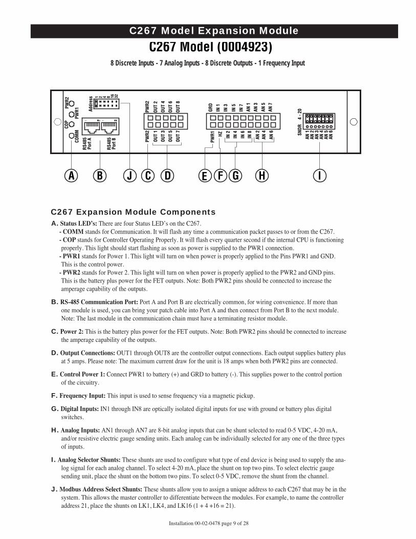
C267 Expansion Module ComponentsA. Status LED’s: There are four Status LED’s on the C267.
- COMM stands for Communication. It will flash any time a communication packet passes to or from the C267.- COP stands for Controller Operating Properly. It will flash every quarter second if the internal CPU is functioningproperly. This light should start flashing as soon as power is supplied to the PWR1 connection.
- PWR1 stands for Power 1. This light will turn on when power is properly applied to the Pins PWR1 and GND.This is the control power.
- PWR2 stands for Power 2. This light will turn on when power is properly applied to the PWR2 and GND pins.This is the battery plus power for the FET outputs. Note: Both PWR2 pins should be connected to increase theamperage capability of the outputs.
B. RS-485 Communication Port: Port A and Port B are electrically common, for wiring convenience. If more thanone module is used, you can bring your patch cable into Port A and then connect from Port B to the next module.Note: The last module in the communication chain must have a terminating resistor module.
C. Power 2: This is the battery plus power for the FET outputs. Note: Both PWR2 pins should be connected to increasethe amperage capability of the outputs.
D. Output Connections: OUT1 through OUT8 are the controller output connections. Each output supplies battery plusat 5 amps. Please note: The maximum current draw for the unit is 18 amps when both PWR2 pins are connected.
E. Control Power 1: Connect PWR1 to battery (+) and GRD to battery (-). This supplies power to the control portionof the circuitry.
F. Frequency Input: This input is used to sense frequency via a magnetic pickup.
G. Digital Inputs: IN1 through IN8 are optically isolated digital inputs for use with ground or battery plus digitalswitches.
H. Analog Inputs: AN1 through AN7 are 8-bit analog inputs that can be shunt selected to read 0-5 VDC, 4-20 mA,and/or resistive electric gauge sending units. Each analog can be individually selected for any one of the three typesof inputs.
I. Analog Selector Shunts: These shunts are used to configure what type of end device is being used to supply the ana-log signal for each analog channel. To select 4-20 mA, place the shunt on top two pins. To select electric gaugesending unit, place the shunt on the bottom two pins. To select 0-5 VDC, remove the shunt from the channel.
J. Modbus Address Select Shunts: These shunts allow you to assign a unique address to each C267 that may be in thesystem. This allows the master controller to differentiate between the modules. For example, to name the controlleraddress 21, place the shunts on LK1, LK4, and LK16 (1 + 4 +16 = 21).
Installation 00-02-0478 page 9 of 28
B
C267 Model (0004923)
RS48
5Po
rt A
PWR1
COM
M
COP
PWR2
PWR2
OUT
1OU
T 2
OUT
3OU
T 4
OUT
5OU
T 6
OUT
7 SNDR
4
- 20
AN 1
AN 2
AN 3
AN 4
AN 5
AN 6
GRD
HZIN
1
IN 3
IN 5
IN 7
AN 1
AN 2
AN 4
AN 6
AN 3
AN 5
AN 7
IN 2
IN 4
IN 6
IN 8
PWR1
OUT
8
PWR2
Addr
ess 1 2 4 8 16 32
RS48
5Po
rt B
A J C D E F G H I
C267 Model Expansion Module
8 Discrete Inputs - 7 Analog Inputs - 8 Discrete Outputs - 1 Frequency Input

C277 Expansion Module ComponentsPOWER UP NOTE: Due to the high accuracy of the readings provided by the C277, a great deal of averagingwill be processed at power-on. If all 18 channels are active, up to 48 seconds are needed to reach full accuracy.Delay configuring or polling the C277 for 8 seconds on power-up. Once this initial power-up sequence is com-plete, each complete update takes about 2 seconds with a filter frequency of 120.
A. Status LED’s: There are four Status LED’s on the C277.- COMM stands for Communication. It will flash any time a communication packet passes to or from the C277.- COP stands for Controller Operating Properly. It will flash every quarter second if the internal CPU is function-ing properly. This light should start flashing as soon as power is supplied to the PWR1 connection.
- PWR1 stands for Power 1. This light will turn on when power is properly applied to the Pins PWR1 and GND.This is the control power.
- PWR2 stands for Power 2. This light will turn on when the internal (minus) 5 VDC supply is functioning properly.B. RS-485 Communication Port: Port A, Port B and Port C are electrically common, for wiring convenience. If
more than one module is used, you can bring your patch cable into Port A and then connect from Port B to thenext module. Port C is available for twisted pair cable connections.Note: The last module in the communication chain must have a terminating resistor module.
C. Modbus Address Select Shunts: These shunts allow you to assign a unique address to each C277 that may be inthe system. This allows the master controller to differentiate between the modules. For example, to name the con-troller address 21, place the shunts on LK1, LK4, and LK16 (1+4+16 = 21).
D. Control Power Terminals: Hook battery (+) to the terminal labeled B+. Hook battery (-) to terminal labeled B-.
E. Channel Connection Terminals: Each channel has two dedicated terminals. The top row is the negative side ofthe connection and the bottom row is the positive side of the connection.
C277 Model (0007620)
RS48
5Po
rt A
PWR1
COM
MCO
P
C277
CO
MM
Se
ries
AN 1
+
AN 2
+
AN 3
+
AN 4
+
AN 5
+
AN 6
+
AN 7
+
AN 8
+
AN 9
+
AN 1
0+
AN 1
1+AN
12+
AN 1
3+
AN 1
4+
AN 1
5+
AN 1
6+
AN 1
7+
AN 1
8+
(-)
(-)
(-)
(-)
(-)
(-)
(-)
(-)
(-)
(-)
(-)
(-)
(-)
(-)
(-)
(-)
(-)
(-)
B+ B–
PWR2
Addr
ess 1 2 4 8 16 32
RS48
5Po
rt B
RS48
5Po
rt C
A B C D E
A– B+
Installation 00-02-0478 page 10 of 28
C277 Model Expansion Module
18 Thermocouples or 4 - 20 mA Inputs

Installation 00-02-0478 page 11 of 28
C287 DesignationA. Status LED’s: There are four Status LED’s on the C287.
- COMM stands for Communication. It will flash any time a communication packet passes to or from the C287.- COP stands for Controller Operating Properly. It will flash every half-second if the internal CPU is functioning
properly. This light should start flashing as soon as power is supplied to the PWR connection.- PWR1 stands for Power 1. This light will turn on when power is properly applied to the Pins PWR1 and GND. This
is the control power.- PWR2 stands for Power 2. This light will turn on when the internal +/- 15 VDC power is functioning properly.
B. RS-485 Communication Port: Port A and Port B are electrically common, for wiring convenience. If more thanone module is used, you can bring your patch cable into Port A and then connect from Port B to the next module.Note: The last module in the communication chain must have a terminating resistor module.
C. Modbus Address Select Shunts: These shunts allow you to assign a unique address to each C287 that may be inthe system. This allows the master controller to differentiate between the modules. For example, to name thecontroller address 21, place the shunts on LK1, LK4, and LK16 (1 + 4 +16 = 21).
D. Control Power: Hook battery (+) to PWR and battery (-) to GND. This supplies power to unit.
E. Analog Loop Power: Hook the analog Loop Power to this input.
F. Analog Outputs: These pins supply the 4-20 mA output current.
G. Analog Inputs: When used as the last unit on an analog loop, ground the AN(-) pin and hook the output from thetransmitter to the AN(+) pin. When used in a loop, bring the output from the transmitter into the AN(+) pin andcome out of the AN(-) pin to the next device.
RS48
5Po
rt A
PWR1
COM
M
COP
GND
PWR
AO 1
AO 3
AO 2
AO 4
AI 1
+AI
1–
AI 2
+AI
2–
AI 3
+AI
3–
AI 4
+AI
4–
LPW
R
PWR2
Addr
ess 1 2 4 8 16 32
RS48
5Po
rt B
A B C D E F G
C287 Model (0005945)
C287 Model Expansion Module
4 Analog Inputs - 4 Analog Outputs

Installation 00-02-0478 page 12 of 28
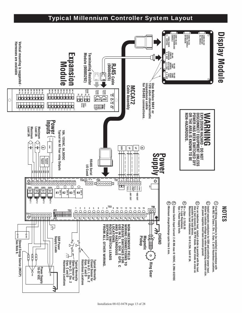
Typical MCPS Power Supply Wiring Diagram
WARNINGEXPLOSION HAZARD - DO NOTDISCONNECT EQUIPMENT UNLESSPOWER HAS BEEN SWITCHED OFFOR THE AREA IS KNOWN TO BENON-HAZARDOUS.
NOTESField Wiring connections to be installed in accordance with the NEC for Class I, Div. 2, Grps. C ad D Hazardous Locations.
Install separate conductors for SSR and controller power input.Allow for coductor voltage drop when determining conductor size.All power supplies must have common ground.
For an inductive load, install a diode in parallel with the load. Use a fast recovery 3A, 50 PIV diode. Mount diode as close aspossible to the load device. maximum load inductance: 1H @ 0.25A, 5mH @ 3A.
Rl = (Vps - 3.15)/0.20Rl = Loop ResistanceVps = Power Supply Volts
Sensor Switch Input Current: 2.45 MA max @ 10VDC, 9.2MA @32VDC
Minimum charge/discharge cycle time 5 min.
1.
2.
3.
4.
5.
6.
MCCA72
RS485 Serial I/O ComA
Future Expansion Port
Separate signal wiring from power
wiring
Separate speed signal wiring from other wiring
10A, 125VAC, 5A,30VDC Typical for All Four relay Outputs
Maximum Load 3A
Power Supply
NON-INCENDIVE FIELD WIRING CONNECTIONS TO PASSIVE SWITCHES FOR USE IN CL. I, DIV. 2 GPS. C AND D HAZARDOUS LOCATIONS.ROUTE SWITCH LEADS SEPARATEFROM ALL OTHER WIRING.
Stored Energy Source (MCCP) See Note 6.
SSR Power Supply Leads
PowerSupply 10-32 VDC
Typical Normally Open Sensor for Use in Cl. I, Div. 2 Grps. C and D Hazardous Locations
Typical Normally Closed Sensor for Use in Cl. I, Div. 2 Grps. C and D Hazardous Locations
Maximum Load 3A
PowerInputs
Ring Gear
Magnetic Pickup
CHGND
TS8
TS6
TS1
JS1
JS2
TS2
TS3
12
34
56
78
9
AN2 OUT
AN1 OUT
OUT 8
OUT 7
OUT 6
OUT 5
OUT 4
OUT 3
OUT 2
OUT 1
1011
1213
1415
16
TS7
K4
K3
K2
K1
TS4
ABCHGND
+-
+-
++
-+
+-
+-
++
--
-+
-+
+-
-
_
_+
+
+_
_+
TS5
+-
-+
-+
-+
-
+
_
I/P
I/P
GOV
MPU
SHG
LOAD
MAXIMUMLOAD 3A
NEG
JR-1
4-20mA
4-20
4-20
4-20
4-20
SHG
SHG
SHG
B1
W1
A1
CurrentSource
4-20mACurrentSource
87
65
43
21
910
1112
1314
1516
NEG
NEG
NEG
SSR1
SSR2
SSR3
SSR4
NO1
C1NC
1NO
2C2
NC2N
O3C3
NC3
NO4
C4NC
4
SSR1
SSR2
SSR3
SSR4
POS
POS
POS
GND
NC
NEG
POS
6A
6A
NEG
POS
3A
NO COM
COM
NEG
NEG
NEG
NEG
POS
POS
POS
POSPOS
MAXIMUMLOAD 3A
3
4
_
+
_+_+
**Use shielded twisted pair wire for speed signal and analog outputs. Connect the shield drain wire at only one end.
*
Installation 00-02-0478 page 13 of 28
RS485 Serial I/O Com
A
10A, 125VAC, 5A,30VDC Typical for All Four relay Outputs
Maxim
um
Load 3A
WARNING
EXPLOSION HAZARD - DO NOTDISCONNECT EQUIPM
ENT UNLESSPOW
ER HAS BEEN SWITCHED OFF
OR THE AREA IS KNOWN TO BE
NON-HAZARDOUS.
Display Module
Power
Supply
ExpansionM
odule
NO
N-IN
CE
ND
IVE
FIE
LD
WIR
ING
CO
NN
EC
TIO
NS
TO
PA
SS
IVE
SW
ITC
HE
S F
OR
US
E IN
CL
. I, DIV
. 2 G
PS
. CA
ND
D H
AZ
AR
DO
US
LO
CA
TIO
NS
.R
OU
TE
SW
ITC
H L
EA
DS
SE
PE
RA
TE
FR
OM
AL
L O
TH
ER
WIR
ING
.
Use
Be
lde
n 9
84
1 o
r 1
20
oh
m ch
ara
cteristic
imp
ed
ance
cab
le
for R
S48
5 co
nn
ectio
ns.
Stored Energy Source (MCCP)
See Note 6.
SSR Power
Supply Leads
Power Supply
10-32 VDC
Typical Normally
Open Sensor for Use in Cl. I, Div. 2 Grps. C and D Hazardous Locations
Typical Normally
Closed Sensor for Use in Cl. I, Div. 2 Grps. C and D Hazardous Locations
Maxim
um
Load 3A
Power
Inputs
MCCA72
Cable Assembly
NOTESField W
iring connections to be installed in accordance with
the NEC for Class I, Div. 2, Grps. C ad D Hazardous Locations.
Install separate conductors for SSR and controller power input.
Allow for coductor voltage drop w
hen determining conductor size.
All power supplies m
ust have comm
on ground.
For an inductive load, install a diode in parallel with the load.
Use a fast recovery 3A, 50 PIV diode. Mount diode as close as
possible to the load device. M
aximum
load inductance: 1H @ 0.25A, 5m
H @ 3A.
Rl = (Vps - 3.15)/0.20Rl = Loop ResistanceVps = Pow
er Supply Volts
Sensor Switch Input Current: 2.45 M
A max @
10VDC, 9.2MA @
32VDC
Minim
um charge/discharge cycle tim
e 5 min.
1.2.3.4.5.6.
Ring Gear
Magnetic
Pickup
CHGND
TS8TS6
TS1JS1
JS2
TS2TS3
TS7TS4
ABCHGND
+-+ -+ + - ++ - + - ++ - - - + - ++ - -
__+ + + _ _+
TS5
+- - + - + - + -
+
_
I/PI/P
GOV
MPU
SHG
RJ45 Cable (00004925)
Terminating Resistor
Module (00005292)
Vertical mounting is suggested -
Harnesses are available
LOAD
MAXIM
UMLOAD 3A
NEG
JR-1
4-20mA
4-20
4-20
4-20
4-20
SHG
SHG
SHGB1
W1
A1
CurrentSource
4-20mA
CurrentSource
87654321 9 10 11 12 13 14 15 16
NEG
NEG
NEG
SSR1 SSR2 SSR3 SSR4 NO1 C1 NC1 NO2 C2 NC2NO3 C3 NC3NO4 C4 NC4
SSR1 SSR2 SSR3 SSR4
POS
POS
POS
GND
NC
NEG
POS
6A6A
NEG
POS
3A
NOCOM
COM
NEG
NEG
NEG
NEG
POS
POS
POS
POSPOS
MAXIM
UMLOAD 3A
3
COM3 RS-232
MODEM
NOTALL M
ODELS
COM2 RS-232
SERIAL CONSOLEOR M
ODEM
COM1 RS-232
DEBUG/DOWNLOAD
CONSOLERS-485
COMB I/O
EXPANSIONB A SHD
COMA POW
ERCONTROL
RS-485COM
CM
ODBUSRTU SLAVEB A SHD
RS-485COM
DSPAREPORT
B A SHD
4
RS485Port A
PWR1
COMM
COP
C277 COM
M
Series
AN 1+
AN 2+
AN 3+
AN 4+
AN 5+
AN 6+
AN 7+
AN 8+
AN 9+
AN 10+
AN 11+AN 12+
AN 13+
AN 14+
AN 15+
AN 16+
AN 17+
AN 18+
(-)
(-)
(-)
(-)(-)
(-)
(-)
(-)
(-)
(-)
(-)
(-)
(-)
(-)
(-)
(-)
(-)
(-)
B+B–
PWR2
Address12481632
RS485Port B
RS485Port C
A–B+
1 2 3 4 5 6 7 8 9
AN2 OUT
AN1 OUT
OUT 8
OUT 7
OUT 6
OUT 5
OUT 4
OUT 3
OUT 2
OUT 1
10 11 12 13 14 15 16
K4 K3 K2 K1
Typical Millennium Controller System Layout

Installation 00-02-0478 page 14 of 28
RJ45 Cable (00004925)
C267 wiring.eps
Ring Gear Magnetic Pickup
To "B+"
Expansion ModuleC267 Model (0004923)
To I/O ExpansionCOMB "B" port onMCH module
(00005292)
- Vertical mounting is suggested - Harnesses are available.- Use Molex crimp pins 39000039 (Murphy 00007181).- Use crimper specifically designed for these Molex pins.- Separate signal wiring from power and output wiring.- Use shielded twisted pair cable for 4-20 mA/Transmitter/ Speed signal wiring.- Connect shield drain wire to ground of the device reading the signal, only.
Separate speed signal wiring from other wiring
= Screw terminal block
NOTE:
RS485Port A
PWR1COMM
COP
PWR2 PWR2
OUT 1 OUT 2
OUT 3 OUT 4
OUT 5 OUT 6
OUT 7
SNDR 4 - 20
AN 1AN 2AN 3AN 4AN 5AN 6
GRD
HZ IN 1
IN 3
IN 5
IN 7AN 1
AN 2
AN 4
AN 6
AN 3
AN 5AN 7
IN 2
IN 4
IN 6IN 8
PWR1
PXMSPXMS
PXMS
PXMS
PXMS
PXMS
PXMS
OUT 8
PWR2
Address12481632
RS485Port B
Typical C267 Module Wiring

RJ45 Cable(00004925)
Cable Assembly(00007197)
SIGNALS POWER & OUTPUTS
Cable Assembly(00007196)
Expansion Module C267 Model (0004923)To Interface Module C267TBIF (0007719)
To I/O ExpansionCOMB "B" port onMCH module
(00005292)
Vertical mounting is suggested - Harnesses are available
MagneticPickup
Ring Gear
PXMS
NOTE:
RS485Port A
PWR1COMM
COP
PWR2 PWR2
OUT 1 OUT 2
OUT 3 OUT 4
OUT 5 OUT 6
OUT 7
SNDR 4 - 20
AN 1AN 2AN 3AN 4AN 5AN 6
GRD
HZ IN 1
IN 3
IN 5
IN 7AN 1
AN 2
AN 4
AN 6
AN 3
AN 5AN 7
LK1
F-GND/
XMTR V+
Signal
Shield
Freq
. IN
AI 1
AI 2
AI 3
AI 4
AI 5
AI 6
AI 7
DI 1
DI 2
DI 3
DI 4
DI 5
DI 6
DI 7
DI 8
DO 1
DO 2
DO 3
DO 4
DO 5
DO 6
DO 7
DO 8
IN 2
IN 4
IN 6IN 8
PWR1
GRD HZ
IN 1
IN 3
IN 5
IN 7
AN 1
AN 2
AN 4
BCD Port
DI Top Row V+/GND (LK1)DI Btm Row SW. IN
DO Top Row Switched V+DO Btm Row GND
AN 6
AN 3
AN 5
AN 7
IN 2
IN 4
IN 6
IN 8
PWR1
OUT 8
PWR2
PWR2
BAT
–
BAT
+
OUT
1OU
T 2
OUT
3OU
T 4
OUT
5OU
T 6
OUT
7OU
T 8
PWR2
Address12481632
RS485Port B
C267TBIF(0007719)
C267 Model(0004923)
Use shielded twisted pair cable with shielded drain wire connected at the EMSTBIF end only.
*
*
*
Typical C267 Module Wiring Using C267TBIF
Installation 00-02-0478 page 15 of 28

Installation 00-02-0478 page 16 of 28
RJ45 Cable(00004925)
Expansion Module C277 Model (0007620)
To I/O ExpansionCOMB "B" port onMCH module
(00005292)
Only shielded, thermocouple grade, thermocouple extension wire should be used. The shield ground (drain wire)should be grounded at the readout instrument.No dissimilar metals should be used to make splices in this wire. For type J and K thermocouples (-) is color coded red. Type J (+) is white, and type K (+) is yellow.For other types consult a thermocouple reference book.Pressure transmitters should be wired using shieldedtwisted pair cabling.Do not use grounded thermocouples.
For best accuracy group thermocoupleinputs from the middle channels, 9 and 10.Locate 4 - 20 mA channels at the firstand last channels.
Vertical mounting is suggested - Harnesses are available
PXM
S
PXM
S
PXM
S
PXM
S
NOTE:
See NOTEbelowB+
W
W
W
W
W
W
W
R
R
W R
W
W
W
R
R
R
R
R
R
R
R
= Screw terminal block
RS485Port A
PWR1COMM COP
C277COMMSeries
AN 1+
AN 2+AN 3+
AN 4+
AN 5+
AN 6+
AN 7+
AN 8+
AN 9+
AN 10+
AN 11+AN 12+
AN 13+
AN 14+
AN 15+
AN 16+
AN 17+
AN 18+
B+
B–
PWR2
Address12481632
RS485Port B
RS485Port C
A–
B+
Typical C277 Module Wiring

Installation 00-02-0478 page 17 of 28
RJ45 Cable(00004925)
Expansion Module C287 Model (0005945)
B+To I/O ExpansionCOMB "B" port onMCH module
(00005292)
Vertical mounting is suggested
PXMS
PXMS
PXMS
PXMS
I/P
I/P
I/P
I/P
RS485Port A
PWR1COMM
COP
GND PWR
AO 1
AO 3AO 2
AO 4
AI 1+ AI 1–
AI 2+ AI 2–
AI 3+ AI 3–
AI 4+ AI 4–
LPWR
PWR2
Address12481632
RS485Port B
- Vertical mounting is suggested - Harnesses are available.- Use Molex crimp pins 39000039 (Murphy 00007181).- Use crimper specifically designed for these Molex pins.- Use shielded twisted pair cable for 4-20 mA/Transmitter/any Analog Input & Output.
= Screw terminal block
NOTE:
Typical C287 Module Wiring

Installation 00-02-0478 page 18 of 28
MCH Module Basic Instructions Turn power on to the MCPS power supply. After approximately 20seconds the first display appears. The following screens are “typical”.Actual screens depend on the program used by the controller.
Press HOME key To Get to The Home ScreenMay need to pressed more than once, depending on cursor position.
To Start the Unit ( from HOME SCREEN)Press "RESET" then "RUN STOP". The display below will beshown and the unit will proceed to the Warmup mode.
To Reset a ShutdownTo reset a shutdown condition press "RESET". The displaybelow shows a typical shutdown screen. To leave these screens,press a navigation key. If more than one shutdown occurs, thedisplay will cycle displaying the Events (1 of 2, etc.).
To See Class B1, B2 &Test Timers press "RIGHT Arrow Key"
To Reset Class B1 Timer in Timer ScreenUse “DOWN” key to get to the B1 TIMER line. Press “RESET”.
To Zero Class B1 Timer in Timer ScreenWith Cursor on B1 Timer line, Press "TIMER "0".
To Reset Class B2 Timer in Timer ScreenUse “DOWN” key to move to the B2 TIMER line.Press "RESET" key.
To Zero Class B2 Timer in Timer ScreenWith Cursor on B2 Timer line, Press "TIMER "0".
Alteratively, from any screen, pressing the"RESET" key willreset both the B1 and B2 Timers. With both Timers active, onepress of "TIMER "0" will zero the B1 Timer and the next press of"TIMER "0" will zero the B2 Timer. Also, from any screen the"TEST MODE" can be initiated and the "TEST" timer zeroed.
To Enter Test Mode Press "TEST" key.To View Test Timer Seconds LeftFrom the Home screen, press "RIGHT ARROW" to get to theTimer Screen and view the Test Timer Value.
To Reset and Zero Test Timer in Timer ScreenMove Cursor down to Test Timer line and press the "RESET"key. The Test Timer will be reset to a standard value of 300 seconds. Press the TIMER "0" key to zero the test timer.
Press "RESET" to reset a shutdown while in Test.
Millennium Controller Basic Instructions
S T : R E A D Y T O S T A R TR P M = 0 H R S = 0 . 0P s = 0 . 0 P d 1 = 0
P d 2 = 0
S T : S T A R T C O M M I T T E DR P M = 0 H R S = 0 . 0P s = 0 . 0 P d 1 = 0
P d 2 = 0
E v e n t 1 o f 10 2 : 0 1 : 5 2 P M 0 4 J A N 0 1S h t d n : 1 s t D i s c h a r g e H i S c r u b b e r L i q L v L .
S T : R E A D Y T O S T A R TR P M = 0 H R S = 0 . 0P s = 0 . 0 P d 1 = 0
P d 2 = 0
S T : R u n n i n g1 0 / 1 9 / 0 1 B 1 = 0 s e c1 8 : 5 8 B 2 = 0 s e cT e s t : O f f T e s t = 3 0 0 s e c
S T : R u n n i n g1 0 / 1 9 / 0 1 B 1 = 0 s e c1 8 : 5 8 B 2 = 0 s e cT e s t : O f f T e s t = 3 0 0 s e c
S T : R u n n i n g1 0 / 1 9 / 0 1 B 1 = 0 s e c1 8 : 5 8 B 2 = 6 0 0 s e cT e s t : O f f T e s t = 3 0 0 s e c
S T : R u n n i n g1 0 / 1 9 / 0 1 B 1 = 0 s e c1 8 : 5 8 B 2 = 0 s e cT e s t : O f f T e s t = 3 0 0 s e c
S T : R u n n i n g1 0 / 1 9 / 0 1 B 1 = 0 s e c1 8 : 5 8 B 2 = 0 s e cT e s t : O n T e s t = 2 9 8 s e c
S T : R u n n i n g1 0 / 1 9 / 0 1 B 1 = 0 s e c1 8 : 5 8 B 2 = 0 s e cT e s t : O f f T e s t = 3 0 0 s e c
S T : R u n n i n g1 0 / 1 9 / 0 1 B 1 = 3 0 0 s e c1 8 : 5 8 B 2 = 0 s e cT e s t : O f f T e s t = 3 0 0 s e c

Installation 00-02-0478 page 19 of 28
DefinitionsApplication – A program written with ISaGRAF that does the functionalcontrol that is downloaded to the Millennium Controller using a PC and theISaGRAF software.
Project – The result of MDesigner screen creation and configuration soft-ware which is downloaded using MDesigner software.
Login – The line that has this is the line where different levels of privileges aregranted based on the pass code used, and the resulting Login level. Login level (5)does not require a code, and is the level when there is not a higher level Login pre-sent. To Login with a higher level code, the cursor must be placed on this line, andthen the ENTER key must be pressed. The cursor will move over the zero dis-played on the right side of that line. A code can now be entered. There are (4) levelsof code, going from level (4), the lowest level of privilege up to level (1), the high-est level of privilege. Level (1) is called the Administrator level, and the privilegesare all encompassing. There is nothing that cannot be done with the Administratorcode. The lower levels have different privileges. For example, level (4), some set-tings are available to be changed that cannot cause improper operation of themachinery. Level (3) is a level where there should be set points that could causeimproper operation of the machine, and not everybody should have access to those.Level (2) is a level where calibration of inputs can be done, and is for higher leveltrained technicians. At the Administrator level, level (1), the Project, and /orApplication can be deleted, outputs can be forced off and on, a Remote Debuggercan be run, the administrator menu is available, and the real time clock can be set.All login levels have a common timer that starts to count down after each key press.If there are no key presses for the length of the Inactive/AutoLogout Delay, then theLogin level will revert back to level (5).
MCH Module Power Up and Self TestTurn on the power to the MCPS power supply. There will be about 20 sec-onds before the display first shows:
The above screen will be present for about 6 seconds after initial power-upand boot-up. If SETUP is pressed and there is an application and projectpresent, the Setup screen will be shown as:
If there is no application or project, the "Login" line and the two "Remove"lines will be missing. If there is no application, but there is a project, onlythe "Remove Application" line will be missing. If there is no project, butthere is an application, only the "Remove Project" line will be missing.
If SETUP is not pressed and there is no project, or no project and no appli-cation, this screen will show next:
Pressing ESC / ACK (Escape) will go back to the Setup Menu to allowSetup Menu selections, such as "Enable Transfer".If SETUP is not pressed and there is a project, but no application, this screenwill show:
This screen will be the only screen available until there is a download fromISaGRAF.If there is a project and a successful download has been done fromISaGRAF, then the application will start.
Remove ApplicationIf "Remove Application" is chosen, the screen will show:
Only choose "Yes" if a PC running ISaGRAF is connected and ready todownload a new, or revised application. If "Yes" is chosen, the applicationwill be removed and the display will show the setup menu again. Set up can be exited by allowing the time to run out, or by pressing “ESC”(Escape), either way the display will show:
= Only present within Administrator Login, Level 1.
MCH Power Up and Self Test Description
M i l l e n n i u mK E R N E L v 0 . 9 6P W R S P L Y v 1 . 7
P r e s s S E T U P f o r M e n u
* S e t u p M e n u *L o g i n ( 5 ) 0E n a b l e T r a n s f e rR e m o v e A p p l i c a t i o n
R e m o v e P r o j e c tR u n F a c t o r y T e s tR u n R e m o t e D e b u g g e rE n a b l e D e b u g M o d e
S e t D a t e & T i m eK e r n a l V 0 . 9 6P o w e r u p V 1 . 7 6P o w e r S u p p l y V 1 . 7
N o A p p l i c a t i o nD e t e c t e d
L i n k w i t h I S a G R A FT o d o w n l o a d
N o A p p l i c a t i o nD e t e c t e d
L i n k w i t h I S a G R A FT o d o w n l o a d
P r o j e c t N o t D e t e c t e dE n a b l e T r a n s f e r
T o d o w n l o a d w i t hM D e s i g n e r
* R e m o v e A p p l i c a t i o n *
A r e y o u s u r e ?E S C = N O E N T E R = Y E S

Installation 00-02-0478 page 20 of 28
Remove ProjectIf "Remove Project" is chosen, the screen will show:
Only choose "Yes" if a PC running MDesigner software is con-nected. If "Yes" is chosen, the second line of the display willchange to the following screen:
When that is complete, the display will show:
From this display press “ESC” (escape) to return to Setup Menu.
Enable TransferFrom the Setup Menu, if "Enable Transfer" is chosen, the screen shows:
With MDesigner running with a project loaded, choose down-load, and the screen will show:
Then the bottom line will change to:
Once the Project has been downloaded, the Setup Menu screen returns.
Run Factory TestTo run the “Factory Test”, two special cables are needed for thecommunications tests to pass. Without the cables, the keypad andthe display can be tested. Here is the test procedure assuming thejumper cables have been plugged into the COMB and COMCports, and COM1 and COM2 ports.Using the DOWN ARROW key, position the cursor on the RunFactory Test line.
Press SETUP/ENTER. The controller will exit the Setup Menu.
The Test will briefly display the version information as shown:
Next the display will change and wait for a key from the keypadto be depressed to begin the test, as shown next:
Press any key, and the display will show:
If each of the communications tests pass, the next test will auto-matically execute. While the test is in process, the bottom linewill be all "?". If it passes, the bottom line will display"PASSED" briefly before moving to the next test. If it fails, thebottom line will display "FAILED". At that time, it should benoted on paper which test failed and then any key can be pressedto execute the next test. The tests in order are:P1 to P2 DATA LINEP2 to P1 DATA LINEP2 to P1 CTS TEST
* R e m o v e P r o j e c t ** D e l e t i n g P r o j e c t *
P r o j e c t N o t D e t e c t e dE n a b l e T r a n s f e r
T o d o w n l o a d w i t hM D e s i g n e r
M i l l e n n i u mE n a b l e T r a n s f e r i n
M D e s i g n e rS c a n n i n g C O M 1
M i l l e n n i u m
I n i t i a l i z i n gP l e a s e S t a n d b y
M i l l e n n i u mD o w n l o a d i n P r o g r e s s
R e c e i v i n g . . .
M i l l e n n i u mD o w n l o a d i n P r o g r e s s
D e c o m p r e s s i n g . . .
MCH Power Up and Self Test Description continued
* R e m o v e P r o j e c t *
A r e y o u s u r e ?E S C = N O E N T E R = Y E S
* T e s t I / O v 1 . 2 ** b y F W M u r p h y ** P r e p a r i n g ** t o T e s t *
* * * * * * * * * * * * * * * * * * * ** P r e s s a n y K e y ** t o B e g i n ** * * * * * * * * * * * * * * * * * * *
C o m m u n i c a t i o n sC h e c k i n g P 1 t o P 2D A T A L I N E? ? ? ? ? ? ? ? ? ? ? ? ? ? ? ?

MCH Power Up and Self Test Description continuedNext, the display will show:
After the Port A (PS) test, the following are tested:PB to PCPC to PB
When the communications tests are done, the display will show:
If all of the characters are displayed properly, press any key. If theyare not displayed properly, note the errors. If any key is pressedacknowledging that this test is passed, the display will show:
If the display shows as what is documented here, press any key. Ifnot, note the errors. If any key is pressed, the display will show:
If all pixels are properly lit, and clearly displayed, press any key.If there is a problem, note the problem. The next test is the keypad test. The display will show:
The display prompts for individual keys to be pressed. 15 secondsis allowed for each prompted keypress. With each correct keypress,the controller will briefly display the key name and address on thebottom line, then briefly display PASSED, and then prompt for thenext keypress. If the wrong key is pressed, or there is a problem sothat the controller sees a key it does not expect, it will display that
key name and address on the bottom line. If the correct key ispressed within the 15 seconds, it will pass. If the correct key is notacknowledged within the 15 seconds, the keypad test will stop atthat point. Make note of any keys failed. This is the order of thekeys to be pressed for the keypad test:
HOME UP PGUP FnLEFT STEP RIGHT (ESC)/ACKAUTO/MAN DOWN PGDOWN SETUP/(Enter)RESET RUN/STOP TEST TIMER "0"
The keys to be pressed start at the upper left, go to the right, thendown a row at the left, and so forth until all keys have been tested.If the keypad test fails, or any other test fails, the display will show:
If all of the tests are passed, the display will show:
After either of these displays, the test is complete. To exit theTest, press “ESC”.
Run Remote Debugger(factory use only).
Enable Debug ModeAllows online monitoring of the application program and data usinga terminal program and a null modem cable. Hyperteminal in Windows can be configured for 115200,N,8,1 and anull modem cable is conected to COM 2 of the Millennium.
Installation 00-02-0478 page 21 of 28
C o m m u n i c a t i o n sC h e c k P o r t A ( P S )D A T A L I N E? ? ? ? ? ? ? ? ? ? ? ? ? ? ? ?
a A b B c C d D e E f F g G h H i I j Jk K l L m M n N o O p P q Q r R s S t Tu U v V w W x X y Y z Za A - z Z O K ?
C G R A M O K ?
K e y p a d T e s tT i m e o u t = x x S e c o n d sP r e s s H O M E k e y? ? ? ? ? ? ? ? ? ? ? ? ? ? ? ?
* * * * * * * * * * * * * * * * * * * ** M i l l e n n i u m T e s t ** F A I L E D ** * * * * * * * * * * * * * * * * * * *
* * * * * * * * * * * * * * * * * * * ** M i l l e n n i u m T e s t ** P A S S E D ** * * * * * * * * * * * * * * * * * * *

Installation MC-01002N page 22 of 28
MC Series Standard Displays - Typical Snapshot
* F A U L T S N A P S H O TT i m e x x : x x D a t e 7 / 1 9S p e e d : x x x R P M
* * * * * P R E S S U R E S * * * * *S u c t i o n x x P S I1 s t D i s c h x x P S I2 n d D i s c h x x P S I
* * * R O D L O A D * * *C y l # 1 C M P : x x x x x L b s
T E N : x x x x x L b s C y l # 2 C M P : x x x x x L b s
* * * * * O I L F L O W * * * * *E n g T o t a l x x x x P t sC o m p T o t a l x x x x P t s
T E N : x x x x x L b sC y l # 3 C M P : x x x x x L b s
T E N : x x x x x L b s
* * * T E M P E R A T U R E S * * *C y l # 1 D i s c : x x x FC y l # 2 D i s c : x x x FC y l # 3 D i s c : x x x F
D i s c h x x x P S I
C y l # 1 E x h a u s t : x x x FC y l # 2 E x h a u s t : x x x FC y l # 3 E x h a u s t : x x x FC y l # 4 E x h a u s t : x x x F
E n g . J k t . W t r . x x x FC o m p . J k t . W t r . x x x FA i r M a n i f o l d x x x FS u c t i o n x x x F

Installation 00-02-0478 page 23 of 28
Setup MenuThis is what the typical Setup Menu looks like. The setup menu is thestarting point to log into other screens.
To access the settings, first press Fn, and then quickly press Setup/Enter.This will show the Setup Menu.
At any time when entering or changing values, the Esc (Escape)/Ack(acknowledge) key can be pressed, instead of the Enter key, whichwould save the change, and the value will revert to what it was beforethe change was attempted.
The top line shows the current login level. Five (5) indicates no privi-leges. Press the Down Arrow key to move the cursor to the Login line.Press enter, enter the code required using the numeric keys, then pressEnter. Your login level will be shown. The login levels are shown in theadministrator Menu. Administrator level is one (1), and allows access toall functions. There are additionally Levels 2, 3, and 4. After a logincode has been entered, the privilege will last for the length of theInactive/Auto Logout timer set in the Administrator Menu. This timer isreset every time a key is pressed after the Login level has been entered.Moving the cursor down using the Down Arrow key to the line "EventList", and pressing Enter will allow viewing the Event List. If the EventList is clear, the cursor will return to the * on the first line. If the eventlist is not clear, the Right Arrow key will move through the Events. TheLeft Arrow key will move back to the last Event.
Event ListThe Events are labeled as a number out of the total number of events.Events are alarms and shutdowns. They are shown as when they becameactive with a date and time stamp, and then when they are acknowledgedwith a date and time stamp. To Exit the Event List, press the Home key.
Shown is a portion of a typical Event List. The first screen shows theevent. The event is a shutdown which was reset. The second screenshows when the shutdown occurred. These are noted by the abbreviation“RST” for reset, and “ACT” for active. Up to 100 events are stored.These will be typically the shutdowns and when they are reset, so thelast 50 shutdowns and their resets are saved.
MC Series Standard Display Menus
* S E T U P M E N U *L o g i n ( 5 ) 0E v e n t L i s t P r o c e s s S e t p o i n t s
A d m i n i s t r a t o r M e n uC l e a r E v e n t L i s tS e t D a t e & T i m eF o r c e M e n u
R S T L o g i n ( 5 ) 5 o f 3 40 7 : 0 6 : 5 5 A M 2 6 J u n 2 0 0 1S h t d n : C o m p r e s s o r H i C o o l a n t T e m p
A C T L o g i n ( 5 ) 4 o f 3 40 7 : 0 6 : 4 9 A M 2 6 J u n 2 0 0 1S h t d n : C o m p r e s s o r H i C o o l a n t T e m p

Installation 00-02-0478 page 24 of 28
MC Series Standard Display Menus
Administrator MenuThis is what the typical Administrator Menu looks like. The Administrator (Level [1]), and Level (2), Level (3), and Level(4)codes can be changed here. It is highly recommended not to change theAdministrator code. The other codes have Murphy default values, simi-lar to other Murphy controllers. For example, comparing to eitherMurphy EMS or S Series controllers, a typical Level (2) code is thesame as the code for the M Numbers, a typical Level (3) code is thesame as the code for the S Numbers, and a typical Level (4) code is thesame as for the P Numbers.
The Inactive/Auto Logout Delay is the length of time after the last keypress the Login Level will go back to Level (5), or no special privileges.This is usually left in the range of 600 seconds, or 10 minutes. If it is settoo short, it can make changing parameters very difficult, because of theneed to re-enter a login whenever the time times out, when the parame-ters have not been fully changed as desired.
The Event Display Delay is the length of time after a key press anyactive Event will be displayed over the current display. Whenever thereis a current Event such as a shutdown, or alarm, that display will beshown until a key is pressed. After a key is pressed, and no more keysare pressed, the Event display will return after this length of time.The Event Cycle Delay is the length of time each Event will stay on the
screen when there are multiple Events that are being displayed in turn.
The Cursor Off Delay is the amount of time after the last key press thecursor will turn itself off. The Notify Message Delay is the length of time a message such as "Fn
Key Active" will show and allow the second key to be pressed.The Modbus Slave Port is COM C. The Baud rate can be change here
from 9600 Baud to 19,200 Baud (19.2 Kbaud), to 38,400 Baud (38.4Kbaud). To do this, the cursor must be on the line where the Baud rateis displayed. ENTER is pressed, then the Baud rate can be changedusing the UP and DOWN keys. When the correct Baud rate is chosenwhich is compatible with the Modbus Master using COM C, ENTER ispressed again, and the Baud rate is selected.
The Power supply Poll Rate and I/O Port Poll Rate can be changed inmultiples of 55 milliseconds. The values here should not be changedwithout consultation with FWMurphy Millennium Controller experts.The values here work well for most all applications. It will only be avery unique application where these values are changed from their typi-cal values.
The choice for Reset Controller can be used to reset the controller. Thishas the same effect as cycling the power, except the power does not haveto be cycled. This is typically used to get to the Power-Up Setup todownload a new application, or project, or do a Factory Test, Transfer afile to or from the DISKONCHIP, such as a trended data file, or any ofthe other functions allowed in the Power-Up Setup Menu.
NOTE: Caution should be used when resetting the controller. The usermust realize that any control functions will cease, and if the equipmentis running, it will be stopped by all outputs dropping out.
The choice for Debug Link Enable is used if it is desired to useISaGRAF software to monitor program and controller operation. Itslightly slows down I/O scan rates to service the ISaGRAF communica-tions through the PC.
Clear Event ListWith the proper level code, if the cursor is navigated to the Clear EventList line, and Enter is pressed, the display on that line will change tosaying "Deleting...". When the dots get to the end of the line, the Eventswill have been cleared.
* C h a n g e P a s s w o r d s *A d m i n i s t r a t o r = 9 9 9 9 9L e v e l 2 = 9 9 9 9 9L e v e l 3 = 9 9 9 9 9
L e v e l 4 = 9 9 9 9 9
I n a c t i v e / A u t o L o g o u tD e l a y 6 0 0 s e c sE v e n t D i s p l a y D e l a y
1 5 s e c s
E v e n t C y c l e D e l a yD e l a y 3 s e c sC u r s o r O f f D e l a y
6 0 s e c s
N o t i f y M e s s a g e D e l a yD e l a y 3 s e c s
M o d b u s S l a v e P o r t B a u d R a t e 9 6 0 0R T U A d d r e s s 1
P w r S u p p l y P o l l R a t eC O M A ( 5 5 m s * ) 2 I / O P o r t P o l l R a t eC O M B ( 5 5 m s * ) 8
R e s e t C o n t r o l l e r N O
D e b u g L i n k E n a b l e N O

Installation 00-02-0478 page 25 of 28
Set Date & Time MenuThis is what the typical Set Date & Time Menu looks like.With the proper level code entered, when the cursor is moved to the SetDate & Time Line, and Enter is pressed, the display will show:
Any or all of the displayed Date and Time data can be set by navigatingto the appropriate line with the Up and Down arrow keys, pressingEnter, entering the corrected data using the numeric keypad, and press-ing Enter, again.
Force MenuThis is what the typical Force Menu looks like. With the proper levelcode entered, when the cursor is moved to the Force Menu, and Enter ispressed, the display will show:
With the administrator login code, the outputs can be forced. First “Enable Force” must be set to “Yes”. Next, the cursor can bemoved to any line where “Off” can be changed to “On”. The analog out-put values can be forced to any value. As long as keys are being pressed,the force time left will be reset to the maximum value. If no keys arepressed, the timer will time out and the forces will be removed.
MC Series Standard Display Menus
* S e t D a t e & T i m e *0 2 / 0 9 / 0 1 1 3 : 0 1D a y ( 1 - 3 1 ) = 0 9M o n t h ( 1 - 1 2 ) = 0 2
Y e a r ( 0 0 - 9 9 ) = 0 1H o u r s ( 0 - 2 3 ) = 1 3M i n s ( 0 - 5 9 ) = 0 1S e c s ( 0 - 5 9 ) = 0 9
* F o r c e M e n u *F o r c e T i m e L e f t : 1 2 0E n a b l e F o r c e : N oD I G I T A L O U T P U T S
8 7 6 5 4 3 2 10 0 0 0 0 0 0 0
O u t p u t 1 : O f fO u t p u t 2 : O f f
O u t p u t 3 : O f fO u t p u t 4 : O f fO u t p u t 5 : O f fO u t p u t 6 : O f f
O u t p u t 7 : O f fO u t p u t 8 : O f fF o r c e T i m e L e f t : 1 2 0A N A L O G O U T P U T S
A n a l o g O u t 1 : 1 0 0 . 0 0S P A N = 6 0 0 0Z E R O = 1 0 0 0
A n a l o g O u t 2 : 1 0 0 . 0
S P A N = 9 5 0Z E R O = 1 0 0
D I G I T A L P O T 2 5 5

Installation 00-02-0478 page 26 of 28
MC Series Troubleshooting Instructions
If There Is No Display on the ControllerCheck the power input to the power supply. It should be between 10 and 32 VDC. Make sure the wiring is per the instructions, and all grounds areproperly connected. If the power to the power supply is within tolerance, check the power to the MCH display head. This can be done by removingthe hood on the head end of the power supply cable. There are two pairs of wires in the power supply cable. The larger gage wires are the power,and with the head connected there should be 5.00 VDC +/- 0.25 VDC at the head end of the cable. If the 5 VDC is not present within tolerance, dis-connect the head and measure the same voltage. The power supply should be able to supply 5.00 VDC +/- 0.25 VDC at up to 3 Amps load. If itcannot perform as explained, return it for repair. If the power is within specifications, return the head for repair.
Checking the Digital InputsThere are LED's for each of the inputs. The status of the inputs is also displayed on one of the standard displays of the Millennium controller head.See Screen A, below. If the input is not working, check the wiring per the instructions. Check to see if jumpers are used, or if external power isused. Use a meter to test the inputs connections for voltage within the published specifications for voltage and current.
Checking the Digital OutputsThe relays have LED's to show their status. Both the relays and the SSR's (Solid State Relays) have their status shown in the standard displays ofthe MCH. See Screen B, below. Make sure the wiring is correct per the instructions. Use a meter to measure voltage and current. On the relays,with no wires connected, a continuity test, or Ohm meter can be used to verify the Common to Normally Open and Common to Normally Closedcontacts. The outputs can be forced. (See Page 25).
Checking the Analog OutputsUse a meter to measure milliAmps. The analog outputs can be forced, zeroed and spanned See Page 25. Make sure the power supply voltage iscorrect for the analog output load. Make sure which model power supply is used. Some power supplies have no analog outputs, some have one, oth-ers have two.
Checking the Speed InputMeasure AC volts and frequency with a meter. Compare to the published specifications.
Screen A Screen B
I n p u t s1 1 1 1 1 1 16 5 4 3 2 1 0 9 8 7 6 5 4 3 2 10 0 0 0 0 0 0 0 0 0 X X 0 0 X 0
O u t p u t s
8 7 6 5 4 3 2 10 0 0 X X 0 0 X

Installation 00-02-0478 page 27 of 28
NOTES
–––––––––––––––––––––––––––––––––––––––––––––––––––––––––––––––––––––––––––––––
–––––––––––––––––––––––––––––––––––––––––––––––––––––––––––––––––––––––––––––––
–––––––––––––––––––––––––––––––––––––––––––––––––––––––––––––––––––––––––––––––
–––––––––––––––––––––––––––––––––––––––––––––––––––––––––––––––––––––––––––––––
–––––––––––––––––––––––––––––––––––––––––––––––––––––––––––––––––––––––––––––––
–––––––––––––––––––––––––––––––––––––––––––––––––––––––––––––––––––––––––––––––
–––––––––––––––––––––––––––––––––––––––––––––––––––––––––––––––––––––––––––––––
–––––––––––––––––––––––––––––––––––––––––––––––––––––––––––––––––––––––––––––––
–––––––––––––––––––––––––––––––––––––––––––––––––––––––––––––––––––––––––––––––
–––––––––––––––––––––––––––––––––––––––––––––––––––––––––––––––––––––––––––––––
–––––––––––––––––––––––––––––––––––––––––––––––––––––––––––––––––––––––––––––––
–––––––––––––––––––––––––––––––––––––––––––––––––––––––––––––––––––––––––––––––
–––––––––––––––––––––––––––––––––––––––––––––––––––––––––––––––––––––––––––––––
–––––––––––––––––––––––––––––––––––––––––––––––––––––––––––––––––––––––––––––––
–––––––––––––––––––––––––––––––––––––––––––––––––––––––––––––––––––––––––––––––
–––––––––––––––––––––––––––––––––––––––––––––––––––––––––––––––––––––––––––––––
–––––––––––––––––––––––––––––––––––––––––––––––––––––––––––––––––––––––––––––––
–––––––––––––––––––––––––––––––––––––––––––––––––––––––––––––––––––––––––––––––
–––––––––––––––––––––––––––––––––––––––––––––––––––––––––––––––––––––––––––––––
–––––––––––––––––––––––––––––––––––––––––––––––––––––––––––––––––––––––––––––––
–––––––––––––––––––––––––––––––––––––––––––––––––––––––––––––––––––––––––––––––
–––––––––––––––––––––––––––––––––––––––––––––––––––––––––––––––––––––––––––––––
–––––––––––––––––––––––––––––––––––––––––––––––––––––––––––––––––––––––––––––––
–––––––––––––––––––––––––––––––––––––––––––––––––––––––––––––––––––––––––––––––
–––––––––––––––––––––––––––––––––––––––––––––––––––––––––––––––––––––––––––––––

Installation 00-02-0478 page 28 of 28
MC Series Options and Accessories
Accessories
Modbus RTU I/O Expansion Modules
Options
Cables and harnesses (for C267, C277 C287)00005293 RJ45 2-foot cable assembly00004925 RJ45 4-foot cable assembly00005292 Terminating Resistor Module00007621 RJ45 to DB9 cable assembly
Cables and harnesses for C267only00007196 HARNESS,C267 10 WIRE MOLEX to C267TBIF00007197 HARNESS,C267 18 WIRE MOLEX to C267TBIF00007719 Interface Terminal board C267TBIF00004924 Molex to raw wires harness, 2 ft. long 35267HRNSKIT
Cables and harnesses for C287only00008544 C287 harness kit 35287HRNSKIT
Configuration and Programming/SoftwareISaGRAF 3.4 256 (WD16) –Ladder logic (IEC-61131-3) programming and monitoring software for up to 256 tag namesISaGRAF 3.4L (WDL) –Ladder logic (IEC-61131-3) programming and monitoring software for unlimited number of tag namesMTools –Display, set point, and alarm screen configuration, initial and default value setting,Modbus register map creation and file transfer utilities.
MCCP Hold-up capacitor package (for 12 VDCcranking battery systems)
C267 (00004923) 8 Digital Inputs, 7 Analog Inputs, Power supply monitor, 8 Discrete outputsC277 (00007620) 18 Thermocouples/4-20 mAC287 (00005945) 4 Analog Inputs, 4 Analog Outputs
In order to consistently bring you the highest quality, full featured products, we reserve the right to change our specifications and designs at any time.
WarrantyA limited warranty on materials and workmanship is given with this FW Murphy product.
A copy of the warranty may be viewed or printed by going to www.fwmurphy.com/support/warranty.htm
CONTROL SYSTEMS & SERVICES DIVISIONP.O. Box 1819Rosenberg, Texas 77471 USAPhone: +1 281 633 4500 Fax: +1 281 633 4588E-mail: [email protected]
FRANK W. MURPHY, LTDChurch Rd LaverstockSalisbury SP1 1QZ UKPhone: +44 172 241 0055 Fax: +44 172 241 0088E-mail: [email protected] site: www.fwmurphy.co.uk
COMPUTRONIC CONTROLS, LTD41 - 43 Railway Terrace NechellsBirmingham B7 5NG UKPhone: +44 121 327 8500 Fax: +44 121 327 8501E-mail: [email protected] site: www.computroniccontrols.com
FW MURPHY INSTRUMENTS (HANGZHOU) CO. LTD 77 23rd StreetHangzhou Economic & Technological Development AreaHangzhou, Zhejiang 310018 ChinaPhone: +86 571 8788 6060 Fax: +86 571 8684 8878
FW MURPHYP.O. Box 470248Tulsa, Oklahoma 74147 USA +1 918 317 4100 Fax: +1 918 317 4266 E-mail: [email protected]
INDUSTRIAL PANEL DIVISIONFax: +1 918 317 4124E-mail: [email protected]
MURPHY POWER IGNITIONWeb site: www.murphy-pi.com
www.fwmurphy.com Printed in U.S.A.