walking control algorithm of biped humanoid robot on uneven and inclined floor
DESCRIPTION
Artigo sobre controleTRANSCRIPT
Walking Control Algorithm of Biped Humanoid Robot on Uneven and Inclined Floor
Jung-Yup Kim, Ill-Woo Park and Jun-Ho Oh
HUBO Laboratory, Humanoid Robot Research Center, Department of Mechanical Engineering,
Korea Advanced Institute of Science and Technology, 373-1 Guseong-dong Yuseong-gu, Daejeon 305-701, South Korea,
E-mail: [email protected] , [email protected] Fax : +82-42-869-8900
ABSTRACT
This paper describes walking control algorithm for the stable walking of a biped humanoid robot on an
uneven and inclined floor. Many walking control techniques have been developed based on the
assumption that the walking surface is perfectly flat with no inclination. Accordingly, most biped
humanoid robots have performed dynamic walking on well designed flat floors. In reality, however, a
typical room floor that appears to be flat has local and global inclinations of about 2 degrees. It is
important to note that even slight unevenness of a floor can cause serious instability in biped walking
robots. In this paper, the authors propose an online control algorithm that considers local and global
inclinations of the floor by which a biped humanoid robot can adapt to the floor conditions. For walking
motions, a suitable walking pattern was designed first. Online controllers were then developed and
activated in suitable periods during a walking cycle. The walking control algorithm was successfully
tested and proved through walking experiments on an uneven and inclined floor using KHR-2 (KAIST
Humanoid robot-2), a test robot platform of our biped humanoid robot, HUBO.
Key words: Walking control, biped humanoid robot, uneven floor, inclined floor, KHR-2
1. INTRODUCTION
Many studies on biped walking robots have been performed since 1970 [1-4]. During that period, biped
walking robots have transformed into biped humanoid robots through the technological development.
Furthermore, the biped humanoid robot has become a one of representative research topics in the
intelligent robot research society. Many researchers anticipate that the humanoid robot industry will be
the industry leader of the 21st century and we eventually enter an era of one robot in every home. The
strong focus on biped humanoid robots stems from a long-standing desire for human-like robots.
Furthermore, a human-like appearance is desirable for coexistence in a human-robot society. However,
while it is not hard to develop a human-like biped robot platform, the realization of stable biped robot
walking poses a considerable challenge. This is because of a lack of understanding on how humans walk
stably. Furthermore, biped walking is an unstable successive motion of a single support phase.
Early biped walking of robots involved static walking with a very low walking speed [5,6]. The step
time was over 10 seconds per step and the balance control strategy was performed through the use of
COG (Center Of Gravity). Hereby the projected point of COG onto the ground always falls within the
supporting polygon that is made by two feet. During the static walking, the robot can stop the walking
motion any time without falling down. The disadvantage of static walking is that the motion is too slow
and wide for shifting the COG.
Researchers thus began to focus on dynamic walking of biped robots [7-9]. It is fast walking with a
speed of less than 1 second per step. If the dynamic balance can be maintained, dynamic walking is
smoother and more active even when using small body motions. However, if the inertial forces generated
from the acceleration of the robot body are not suitably controlled, a biped robot easily falls down. In
addition, during dynamic walking, a biped robot may falls down from disturbances and cannot stop the
walking motion suddenly. Hence, the notion of ZMP (Zero Moment Point) was introduced in order to
control inertial forces [10, 11]. In the stable single support phase, the ZMP is equal to the COP (Center of
Pressure) on the sole. The advantage of the ZMP is that it is a point where the center of gravity is
projected onto the ground in the static state and a point where the total inertial force composed of the
gravitational force and inertial force of mass goes through the ground in the dynamic state. If the ZMP
strictly exists within the supporting polygon made by the feet, the robot never falls down. Most research
groups have used the ZMP as a walking stability criterion of dynamic biped walking. To this end, the
robot is controlled such that the ZMP is maintained within the supporting polygon.
In general, the walking control strategies using the ZMP can be divided into two approaches. First, the
robot can be modeled by considering many point masses, the locations of the point masses and the mass
moments of inertia of the linkages. The walking pattern is then calculated by solving ZMP dynamics
derived from the robot model with a desired ZMP trajectory. During walking, sensory feed back is used to
control the robot. Second, the robot is modeled by a simple mathematical model such as an inverted
pendulum system, and then the walking pattern is designed based on the limited information of a simple
model and experimental hand tuning. During walking, many kinds of online controllers are activated to
compensate the walking motion through the use of various sensory feedback data including the ZMP. The
first approach can derive a precise walking pattern that satisfies the desired ZMP trajectory, but it is hard
to generate the walking pattern in real-time due to the large calculation burden. Further, if the
mathematical model is different from the real robot, the performance is diminished. On the contrary, the
second approach can easily generate the walking pattern online. However, many kinds of online
controllers are needed to compensate the walking pattern in real-time, because the prescribed walking
pattern cannot satisfy the desired ZMP trajectory. In addition, this method depends strongly on the
sensory feedback, and hence the walking ability is limited to the sensor’s performance and requires
considerable experimental hand tuning. The authors have developed biped humanoid robots through the
second approach [12, 13]. Specifically, various online controllers are activated and switched in the
successive walking cycle.
At present, biped humanoid robot research groups have developed their own robot platforms and
dynamic walking control algorithms. For example, ASIMO of HONDA, WABIAN-2 of Waseda
University, and HRP-3 of AIST are well known biped humanoid robots. To date, most biped humanoid
robots have performed stable dynamic walking on the well prepared flat floors. Studies involving walking
on the uneven and inclined floors are still in the early stage [14, 15]. Dynamic walking on an uneven
surface is hard to realize because most biped humanoid robots perform hard position control of the joints
by using motors and reduction gears and the response times of the actuators and sensors are low due to
the reduction gear and sensor noise. Accordingly, it is impossible for the robot to measure the ground
conditions instantaneously and it is also impossible for the robot to appropriately respond even if it
measures the ground conditions rapidly. On the contrary, the human ankle can rapidly adapt to changing
ground conditions. Furthermore, human muscles can contract or relax quickly with smooth motions.
This paper described a dynamic walking control algorithm that considers local and global inclinations
of the floor. The authors propose the use of various online controllers to cope with an uneven and inclined
floor based on an enhanced version of a previously proposed dynamic walking algorithm [13]. These
online controllers are activated successively within a suitable time in a walking cycle. The performance of
the algorithm is demonstrated in walking experiments using KHR-2.
This remainder of this paper is organized as follows: In Section 2, KHR-2, the test robot platform, is
introduced. In Section 3, the walking pattern generation scheme for walking motion, the online controller
design considering floor conditions, and activation of the online controllers during a walking cycle are
described. In Section 4, the performance of the proposed walking control algorithm is assessed and
demonstrated through walking experiments involving various floor conditions. Finally, Section 5
concludes the paper a discussion and plan for future work.
2. BIPED HUMANOID ROBOT PLATFORM, KHR-2
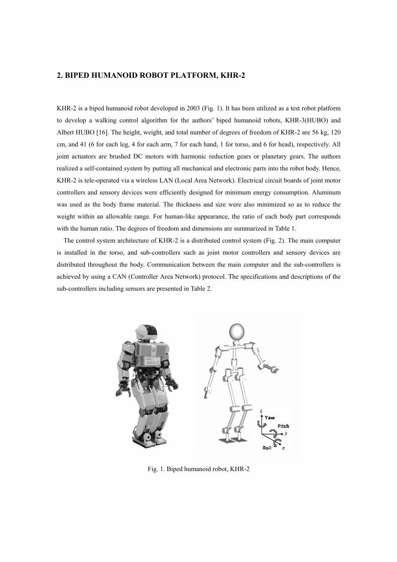
KHR-2 is a biped humanoid robot developed in 2003 (Fig. 1). It has been utilized as a test robot platform
to develop a walking control algorithm for the authors’ biped humanoid robots, KHR-3(HUBO) and
Albert HUBO [16]. The height, weight, and total number of degrees of freedom of KHR-2 are 56 kg, 120
cm, and 41 (6 for each leg, 4 for each arm, 7 for each hand, 1 for torso, and 6 for head), respectively. All
joint actuators are brushed DC motors with harmonic reduction gears or planetary gears. The authors
realized a self-contained system by putting all mechanical and electronic parts into the robot body. Hence,
KHR-2 is tele-operated via a wireless LAN (Local Area Network). Electrical circuit boards of joint motor
controllers and sensory devices were efficiently designed for minimum energy consumption. Aluminum
was used as the body frame material. The thickness and size were also minimized so as to reduce the
weight within an allowable range. For human-like appearance, the ratio of each body part corresponds
with the human ratio. The degrees of freedom and dimensions are summarized in Table 1.
The control system architecture of KHR-2 is a distributed control system (Fig. 2). The main computer
is installed in the torso, and sub-controllers such as joint motor controllers and sensory devices are
distributed throughout the body. Communication between the main computer and the sub-controllers is
achieved by using a CAN (Controller Area Network) protocol. The specifications and descriptions of the
sub-controllers including sensors are presented in Table 2.
Fig. 1. Biped humanoid robot, KHR-2
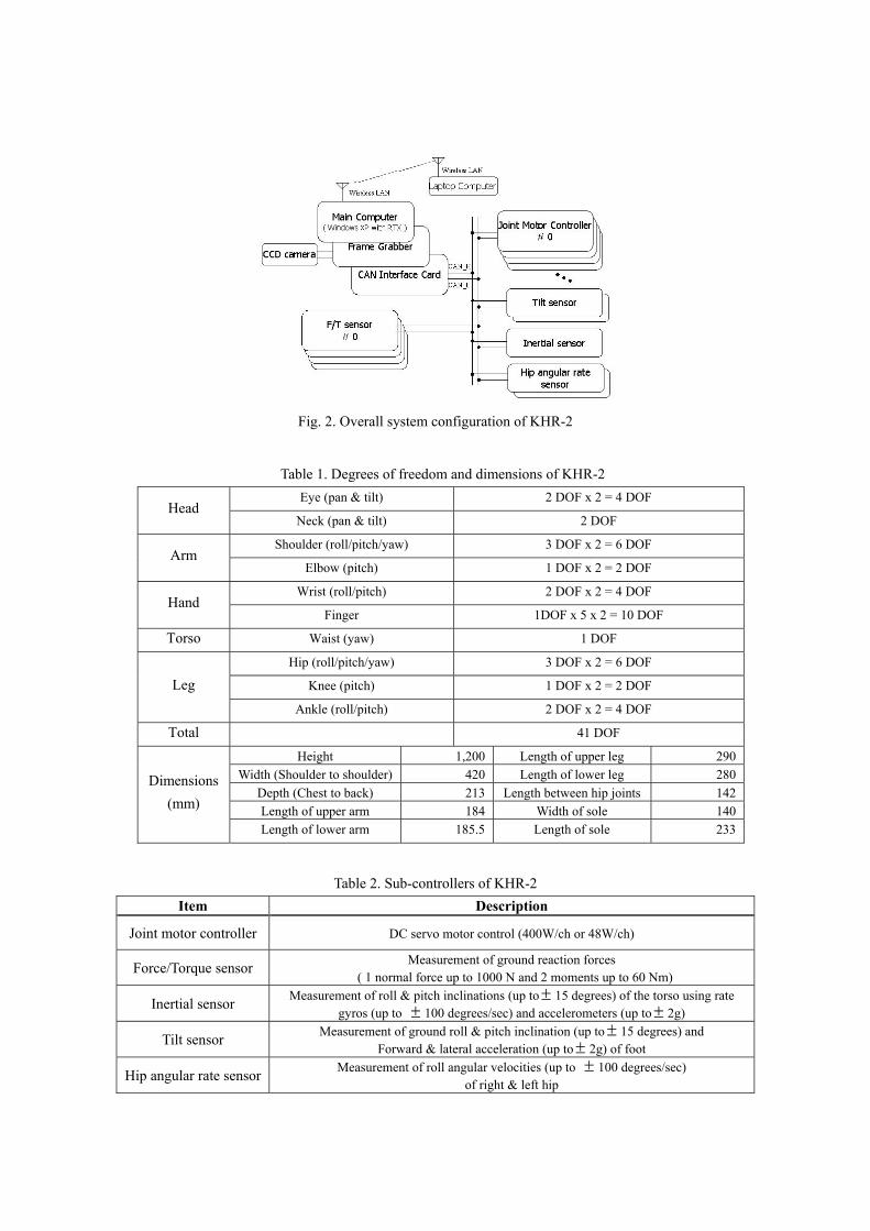
Fig. 2. Overall system configuration of KHR-2
Table 1. Degrees of freedom and dimensions of KHR-2 Eye (pan & tilt) 2 DOF x 2 = 4 DOF
Head Neck (pan & tilt) 2 DOF
Shoulder (roll/pitch/yaw) 3 DOF x 2 = 6 DOF Arm
Elbow (pitch) 1 DOF x 2 = 2 DOF
Wrist (roll/pitch) 2 DOF x 2 = 4 DOF Hand
Finger 1DOF x 5 x 2 = 10 DOF
Torso Waist (yaw) 1 DOF
Hip (roll/pitch/yaw) 3 DOF x 2 = 6 DOF
Knee (pitch) 1 DOF x 2 = 2 DOF Leg Ankle (roll/pitch) 2 DOF x 2 = 4 DOF
Total 41 DOF
Height 1,200 Length of upper leg 290Width (Shoulder to shoulder) 420 Length of lower leg 280
Depth (Chest to back) 213 Length between hip joints 142Length of upper arm 184 Width of sole 140
Dimensions (mm)
Length of lower arm 185.5 Length of sole 233
Table 2. Sub-controllers of KHR-2 Item Description
Joint motor controller DC servo motor control (400W/ch or 48W/ch)
Force/Torque sensor Measurement of ground reaction forces ( 1 normal force up to 1000 N and 2 moments up to 60 Nm)
Inertial sensor Measurement of roll & pitch inclinations (up to± 15 degrees) of the torso using rate gyros (up to ± 100 degrees/sec) and accelerometers (up to± 2g)
Tilt sensor Measurement of ground roll & pitch inclination (up to± 15 degrees) and Forward & lateral acceleration (up to± 2g) of foot
Hip angular rate sensor Measurement of roll angular velocities (up to ± 100 degrees/sec) of right & left hip
3. BIPED WALKING AND ONLINE CONTROL ALGORITHM CONSIDERING
FLOOR CONDITION
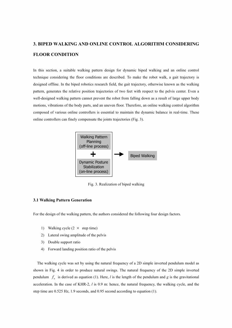
In this section, a suitable walking pattern design for dynamic biped walking and an online control
technique considering the floor conditions are described. To make the robot walk, a gait trajectory is
designed offline. In the biped robotics research field, the gait trajectory, otherwise known as the walking
pattern, generates the relative position trajectories of two feet with respect to the pelvis center. Even a
well-designed walking pattern cannot prevent the robot from falling down as a result of large upper body
motions, vibrations of the body parts, and an uneven floor. Therefore, an online walking control algorithm
composed of various online controllers is essential to maintain the dynamic balance in real-time. These
online controllers can finely compensate the joints trajectories (Fig. 3).
Fig. 3. Realization of biped walking
3.1 Walking Pattern Generation
For the design of the walking pattern, the authors considered the following four design factors.
1) Walking cycle (2 × step time)
2) Lateral swing amplitude of the pelvis
3) Double support ratio
4) Forward landing position ratio of the pelvis
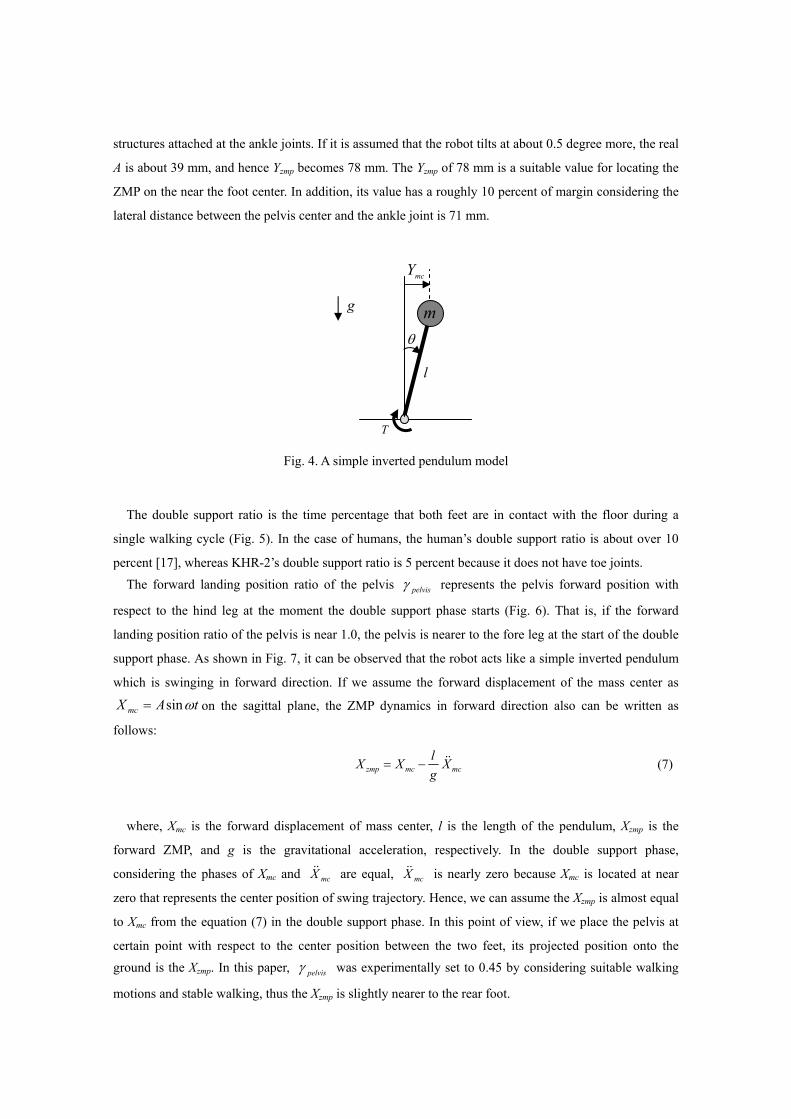
The walking cycle was set by using the natural frequency of a 2D simple inverted pendulum model as
shown in Fig. 4 in order to produce natural swings. The natural frequency of the 2D simple inverted
pendulum nf is derived as equation (1). Here, l is the length of the pendulum and g is the gravitational
acceleration. In the case of KHR-2, l is 0.9 m: hence, the natural frequency, the walking cycle, and the
step time are 0.525 Hz, 1.9 seconds, and 0.95 second according to equation (1).
Walking PatternPlanning
(off-line process)
Dynamic PostureStabilization
(on-line process)
Biped Walking
lgf n π2
1= (1)
The lateral swing amplitude of the pelvis also can be derived by means of the ZMP dynamics of a 2D
simple inverted pendulum model. The equation of motion of a simple inverted pendulum model can be
written as follows;
θθ &&2mlmglT −= (2)
Where, T is the torque at the joint, m is the point mass and θ is the angular displacement. Then, if we
divide the right and left parts by mg, we have
( )θθ &&lgll
mgT
−= (3)
By substituting zF = mg and θl = mcY into equation (3) under an assumption that θ is small (θ < 5
degrees), then we obtain
( )mcmcz
YglY
FT &&−= (4)
Where, zF is the ground reaction force, Ymc is the lateral displacement of mass center. ZMP is
practically calculated through dividing the torque T at the joint by the ground reaction force zF . Thus,
we can finally get following ZMP dynamics.
mcmczmp YglYY &&−= (5)
Where, Yzmp is the lateral ZMP. When the robot is walking, we can assume the lateral displacement of
the mass center as tAYmc ωsin= on the coronal plane. Then, we obtain
tglAYzmp ωω sin1 2
⎟⎟⎠
⎞⎜⎜⎝
⎛+= (6)
Here, when the walking frequency )2( nfπω = and the lateral swing amplitude of the pelvis A are
chosen as 3.3 rad/sec and 32 mm, the amplitude of Yzmp becomes 64 mm. Moreover, in real robot’s
walking, A becomes larger than the original value due to deflection of the compliant force/torque sensor
structures attached at the ankle joints. If it is assumed that the robot tilts at about 0.5 degree more, the real
A is about 39 mm, and hence Yzmp becomes 78 mm. The Yzmp of 78 mm is a suitable value for locating the
ZMP on the near the foot center. In addition, its value has a roughly 10 percent of margin considering the
lateral distance between the pelvis center and the ankle joint is 71 mm.
Fig. 4. A simple inverted pendulum model
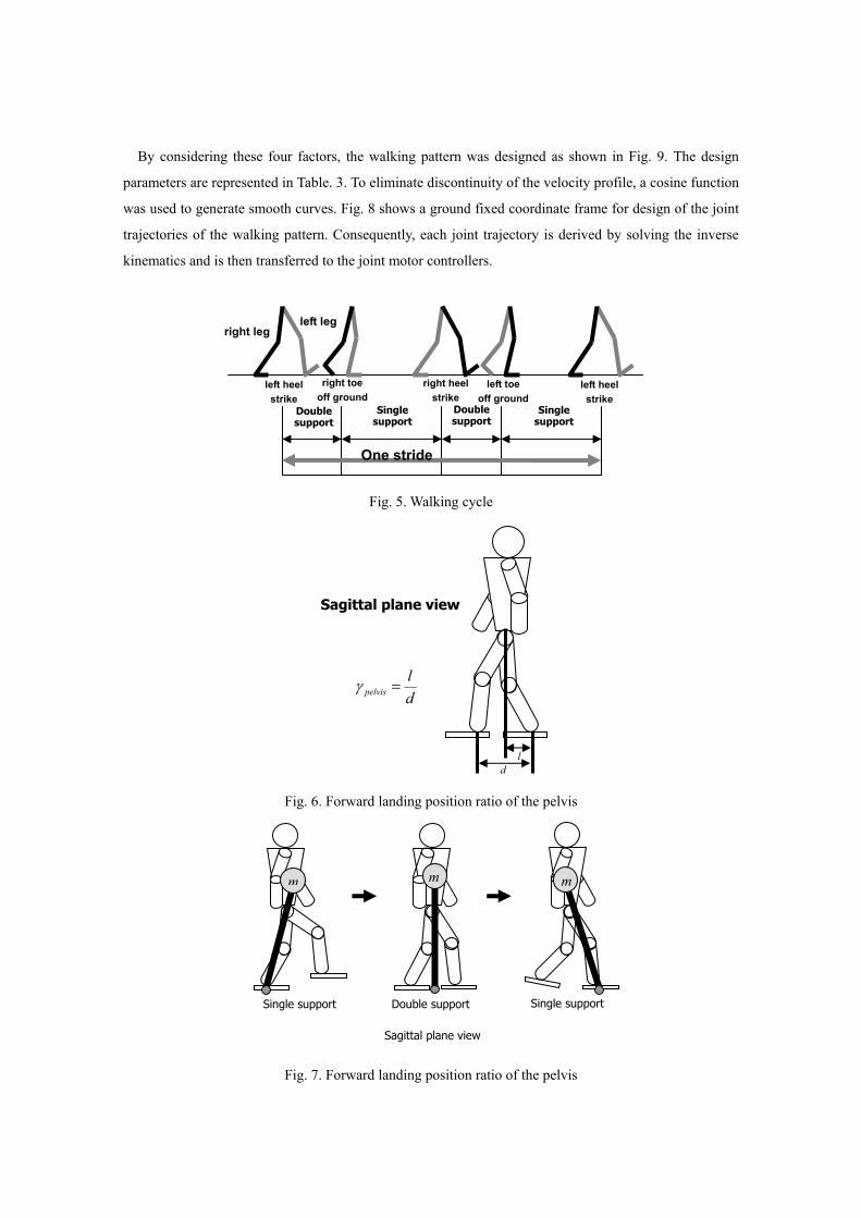
The double support ratio is the time percentage that both feet are in contact with the floor during a
single walking cycle (Fig. 5). In the case of humans, the human’s double support ratio is about over 10
percent [17], whereas KHR-2’s double support ratio is 5 percent because it does not have toe joints. The forward landing position ratio of the pelvis pelvisγ represents the pelvis forward position with
respect to the hind leg at the moment the double support phase starts (Fig. 6). That is, if the forward
landing position ratio of the pelvis is near 1.0, the pelvis is nearer to the fore leg at the start of the double
support phase. As shown in Fig. 7, it can be observed that the robot acts like a simple inverted pendulum
which is swinging in forward direction. If we assume the forward displacement of the mass center as
tAX mc ωsin= on the sagittal plane, the ZMP dynamics in forward direction also can be written as
follows:
mcmczmp XglXX &&−= (7)
where, Xmc is the forward displacement of mass center, l is the length of the pendulum, Xzmp is the
forward ZMP, and g is the gravitational acceleration, respectively. In the double support phase,
considering the phases of Xmc and mcX&& are equal, mcX&& is nearly zero because Xmc is located at near
zero that represents the center position of swing trajectory. Hence, we can assume the Xzmp is almost equal
to Xmc from the equation (7) in the double support phase. In this point of view, if we place the pelvis at
certain point with respect to the center position between the two feet, its projected position onto the ground is the Xzmp. In this paper, pelvisγ was experimentally set to 0.45 by considering suitable walking
motions and stable walking, thus the Xzmp is slightly nearer to the rear foot.
θ
g
l
m
mcY
T
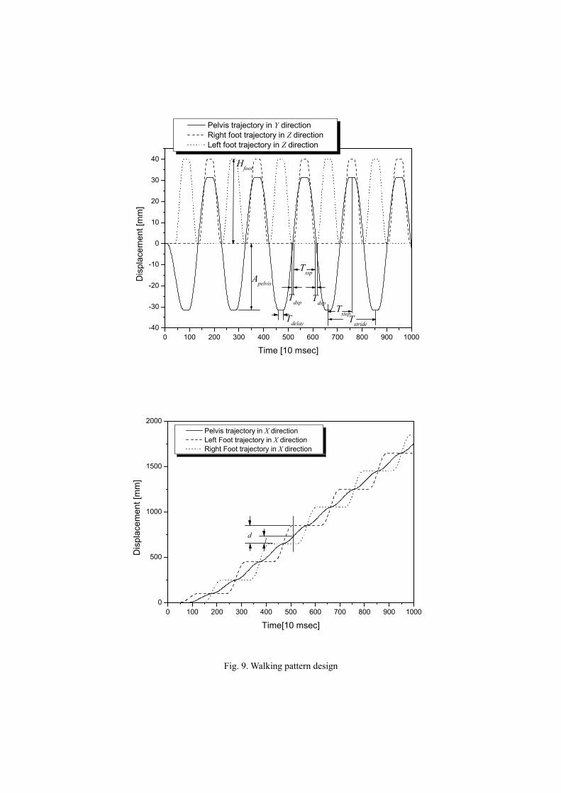
By considering these four factors, the walking pattern was designed as shown in Fig. 9. The design
parameters are represented in Table. 3. To eliminate discontinuity of the velocity profile, a cosine function
was used to generate smooth curves. Fig. 8 shows a ground fixed coordinate frame for design of the joint
trajectories of the walking pattern. Consequently, each joint trajectory is derived by solving the inverse
kinematics and is then transferred to the joint motor controllers.
Fig. 5. Walking cycle
Fig. 6. Forward landing position ratio of the pelvis
Fig. 7. Forward landing position ratio of the pelvis
right leg left leg
left heel strike
right heel strike
left heel strike
right toe off ground
left toe off ground
Double support
Double support
Single support
Single support
One stride
d
Sagittal plane view
l
dl
pelvis =γ
Sagittal plane view
m m m
Single support Double support Single support
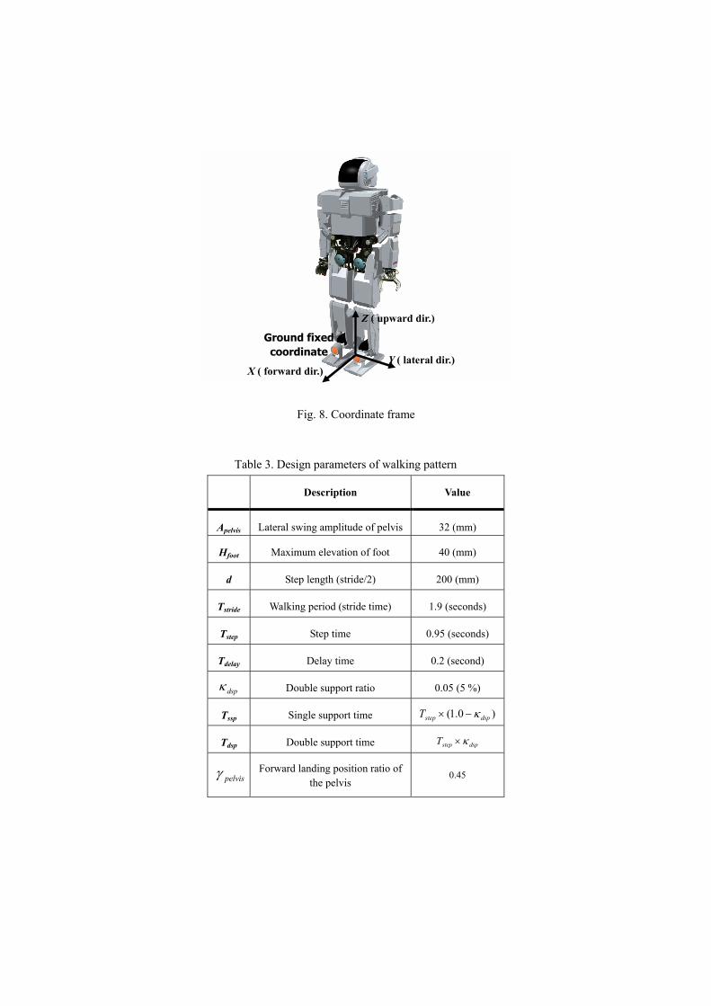
Fig. 8. Coordinate frame
Table 3. Design parameters of walking pattern
Description Value
Apelvis Lateral swing amplitude of pelvis 32 (mm)
Hfoot Maximum elevation of foot 40 (mm)
d Step length (stride/2) 200 (mm)
Tstride Walking period (stride time) 1.9 (seconds)
Tstep Step time 0.95 (seconds)
Tdelay Delay time 0.2 (second)
dspκ Double support ratio 0.05 (5 %)
Tssp Single support time )0.1( dspstepT κ−×
Tdsp Double support time dspstepT κ×
pelvisγ Forward landing position ratio of the pelvis
0.45
Y ( lateral dir.)
Z ( upward dir.)
Ground fixed coordinate
X ( forward dir.)
0 100 200 300 400 500 600 700 800 900 1000-40
-30
-20
-10
0
10
20
30
40
Apelvis
Hfoot
Tstep
Tssp
TdspTdsp
TstrideTdelay
D
ispl
acem
ent [
mm
]
Time [10 msec]
Pelvis trajectory in Y direction Right foot trajectory in Z direction Left foot trajectory in Z direction
0 100 200 300 400 500 600 700 800 900 10000
500
1000
1500
2000
l
Dis
plac
emen
t [m
m]
Time[10 msec]
Pelvis trajectory in X direction Left Foot trajectory in X direction Right Foot trajectory in X direction
d
Fig. 9. Walking pattern design
3.2 Walking Control Algorithm
In this section, the authors proposed an online controller design and suitable use of online controllers in a
walking cycle. The proposed walking control method is based on a controller switching strategy, and thus
it is important to divide the walking cycle into several walking stages. In each walking stage, suitable
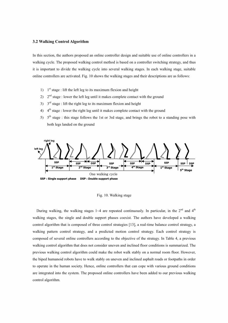
online controllers are activated. Fig. 10 shows the walking stages and their descriptions are as follows:
1) 1st stage : lift the left leg to its maximum flexion and height
2) 2nd stage : lower the left leg until it makes complete contact with the ground
3) 3rd stage : lift the right leg to its maximum flexion and height
4) 4th stage : lower the right leg until it makes complete contact with the ground
5) 5th stage : this stage follows the 1st or 3rd stage, and brings the robot to a standing pose with
both legs landed on the ground
Fig. 10. Walking stage
During walking, the walking stages 1~4 are repeated continuously. In particular, in the 2nd and 4th
walking stages, the single and double support phases coexist. The authors have developed a walking
control algorithm that is composed of three control strategies [13], a real-time balance control strategy, a
walking pattern control strategy, and a predicted motion control strategy. Each control strategy is
composed of several online controllers according to the objective of the strategy. In Table 4, a previous
walking control algorithm that does not consider uneven and inclined floor conditions is summarized. The
previous walking control algorithm could make the robot walk stably on a normal room floor. However,
the biped humanoid robots have to walk stably on uneven and inclined asphalt roads or footpaths in order
to operate in the human society. Hence, online controllers that can cope with various ground conditions
are integrated into the system. The proposed online controllers have been added to our previous walking
control algorithm.
left leg
right leg
1st Stage 2nd Stage 3rd Stage 4th Stage SSP DSP SSP DSP
SSP : Single support phase DSP : Double support phase
1st Stage 5th Stage
One walking cycle
SSP SSP SSP SSP DSP
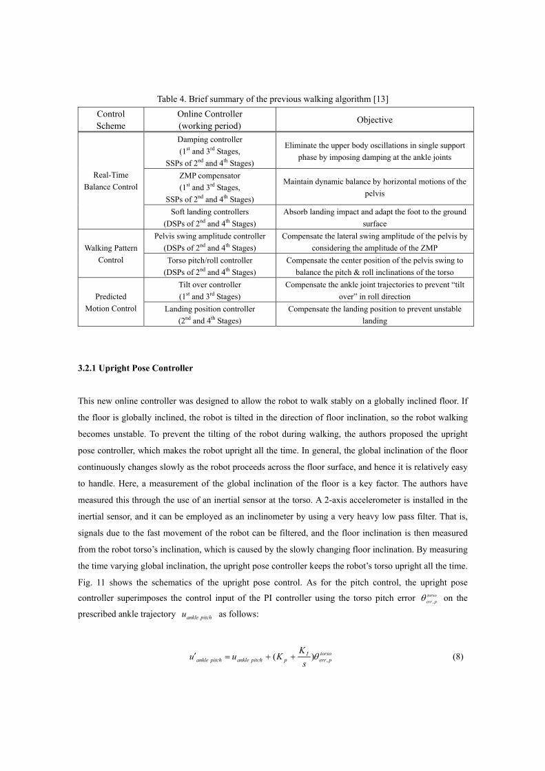
Table 4. Brief summary of the previous walking algorithm [13] Control Scheme
Online Controller (working period) Objective
Damping controller (1st and 3rd Stages,
SSPs of 2nd and 4th Stages)
Eliminate the upper body oscillations in single support phase by imposing damping at the ankle joints
ZMP compensator (1st and 3rd Stages,
SSPs of 2nd and 4th Stages)
Maintain dynamic balance by horizontal motions of the pelvis
Real-Time Balance Control
Soft landing controllers (DSPs of 2nd and 4th Stages)
Absorb landing impact and adapt the foot to the ground surface
Pelvis swing amplitude controller (DSPs of 2nd and 4th Stages)
Compensate the lateral swing amplitude of the pelvis by considering the amplitude of the ZMP Walking Pattern
Control Torso pitch/roll controller (DSPs of 2nd and 4th Stages)
Compensate the center position of the pelvis swing to balance the pitch & roll inclinations of the torso
Tilt over controller (1st and 3rd Stages)
Compensate the ankle joint trajectories to prevent “tilt over” in roll direction Predicted
Motion Control Landing position controller (2nd and 4th Stages)
Compensate the landing position to prevent unstable landing
3.2.1 Upright Pose Controller
This new online controller was designed to allow the robot to walk stably on a globally inclined floor. If
the floor is globally inclined, the robot is tilted in the direction of floor inclination, so the robot walking
becomes unstable. To prevent the tilting of the robot during walking, the authors proposed the upright
pose controller, which makes the robot upright all the time. In general, the global inclination of the floor
continuously changes slowly as the robot proceeds across the floor surface, and hence it is relatively easy
to handle. Here, a measurement of the global inclination of the floor is a key factor. The authors have
measured this through the use of an inertial sensor at the torso. A 2-axis accelerometer is installed in the
inertial sensor, and it can be employed as an inclinometer by using a very heavy low pass filter. That is,
signals due to the fast movement of the robot can be filtered, and the floor inclination is then measured
from the robot torso’s inclination, which is caused by the slowly changing floor inclination. By measuring
the time varying global inclination, the upright pose controller keeps the robot’s torso upright all the time.
Fig. 11 shows the schematics of the upright pose control. As for the pitch control, the upright pose
controller superimposes the control input of the PI controller using the torso pitch error torsoperr ,θ on the
prescribed ankle trajectory pitchankleu as follows:
torsoperr
Ippitchanklepitchankle s
KKuu ,)( θ++=′ (8)
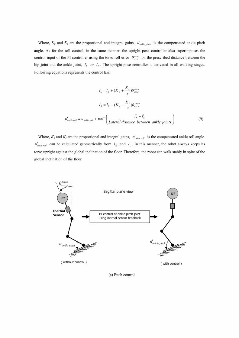
Where, Kp and KI are the proportional and integral gains, pitchankleu′ is the compensated ankle pitch
angle. As for the roll control, in the same manner, the upright pose controller also superimposes the
control input of the PI controller using the torso roll error torsorerr ,θ on the prescribed distance between the
hip joint and the ankle joint, Rl or Ll . The upright pose controller is activated in all walking stages.
Following equations represents the control law.
torsorerr
IpLL s
KKll ,)( θ++=′
torsorerr
IpRR s
KKll ,)( θ+−=′
⎟⎟⎠
⎞⎜⎜⎝
⎛ ′−′+=′ −
jointsnkleabetweendistance Lateralll
uu LRrollanklerollankle
1tan (9)
Where, Kp and KI are the proportional and integral gains, rollankleu′ is the compensated ankle roll angle.
rollankleu′ can be calculated geometrically from Rl and Ll . In this manner, the robot always keeps its
torso upright against the global inclination of the floor. Therefore, the robot can walk stably in spite of the
global inclination of the floor.
(a) Pitch control
mSagittal plane view
( without control ) ( with control )
m
PI control of ankle pitch joint using inertial sensor feedback
Inertial Sensor
torsoperr ,θ
pitchankleu pitchankleu′
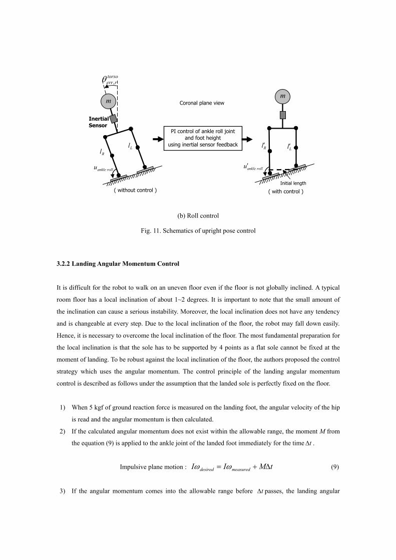
(b) Roll control
Fig. 11. Schematics of upright pose control
3.2.2 Landing Angular Momentum Control
It is difficult for the robot to walk on an uneven floor even if the floor is not globally inclined. A typical
room floor has a local inclination of about 1~2 degrees. It is important to note that the small amount of
the inclination can cause a serious instability. Moreover, the local inclination does not have any tendency
and is changeable at every step. Due to the local inclination of the floor, the robot may fall down easily.
Hence, it is necessary to overcome the local inclination of the floor. The most fundamental preparation for
the local inclination is that the sole has to be supported by 4 points as a flat sole cannot be fixed at the
moment of landing. To be robust against the local inclination of the floor, the authors proposed the control
strategy which uses the angular momentum. The control principle of the landing angular momentum
control is described as follows under the assumption that the landed sole is perfectly fixed on the floor.
1) When 5 kgf of ground reaction force is measured on the landing foot, the angular velocity of the hip
is read and the angular momentum is then calculated.
2) If the calculated angular momentum does not exist within the allowable range, the moment M from
the equation (9) is applied to the ankle joint of the landed foot immediately for the time t∆ .
Impulsive plane motion : tMII measureddesired ∆+= ωω (9)
3) If the angular momentum comes into the allowable range before t∆ passes, the landing angular
m Coronal plane view
Inertial Sensor
Initial length ( without control ) ( with control )
PI control of ankle roll joint and foot height
using inertial sensor feedback
m
torsorerr,θ
rollankleu rollankleu′
Rl Ll Rl′ Ll′
momentum control is deactivated.
In equation (9) above, measuredIω is the real angular momentum after landing, desiredIω is the desired
angular momentum after landing, M is the moment applied to the ankle joint of the landed foot, and ∆ t
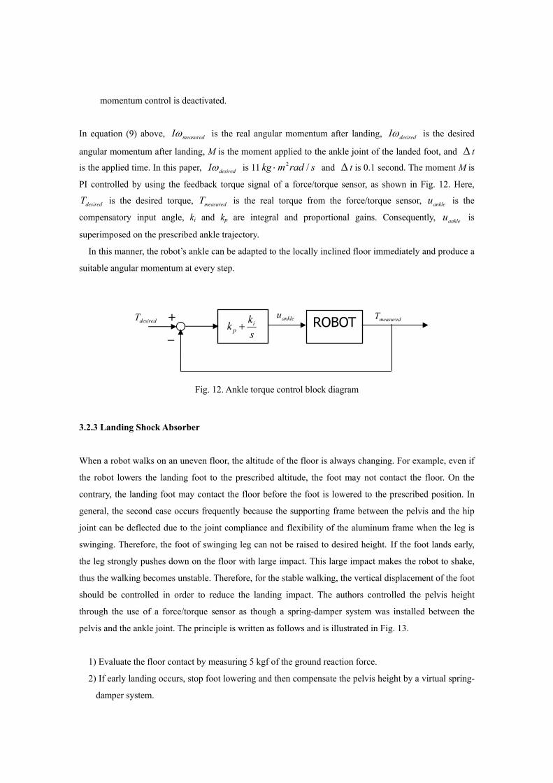
is the applied time. In this paper, desiredIω is 11 sradmkg /2⋅ and ∆ t is 0.1 second. The moment M is
PI controlled by using the feedback torque signal of a force/torque sensor, as shown in Fig. 12. Here,
desiredT is the desired torque, measuredT is the real torque from the force/torque sensor, ankleu is the
compensatory input angle, ki and kp are integral and proportional gains. Consequently, ankleu is
superimposed on the prescribed ankle trajectory.
In this manner, the robot’s ankle can be adapted to the locally inclined floor immediately and produce a
suitable angular momentum at every step.
Fig. 12. Ankle torque control block diagram
3.2.3 Landing Shock Absorber
When a robot walks on an uneven floor, the altitude of the floor is always changing. For example, even if
the robot lowers the landing foot to the prescribed altitude, the foot may not contact the floor. On the
contrary, the landing foot may contact the floor before the foot is lowered to the prescribed position. In
general, the second case occurs frequently because the supporting frame between the pelvis and the hip
joint can be deflected due to the joint compliance and flexibility of the aluminum frame when the leg is
swinging. Therefore, the foot of swinging leg can not be raised to desired height. If the foot lands early,
the leg strongly pushes down on the floor with large impact. This large impact makes the robot to shake,
thus the walking becomes unstable. Therefore, for the stable walking, the vertical displacement of the foot
should be controlled in order to reduce the landing impact. The authors controlled the pelvis height
through the use of a force/torque sensor as though a spring-damper system was installed between the
pelvis and the ankle joint. The principle is written as follows and is illustrated in Fig. 13.
1) Evaluate the floor contact by measuring 5 kgf of the ground reaction force.
2) If early landing occurs, stop foot lowering and then compensate the pelvis height by a virtual spring-
damper system.
ROBOT+
-
desiredT measuredT skk i
p +ankleu
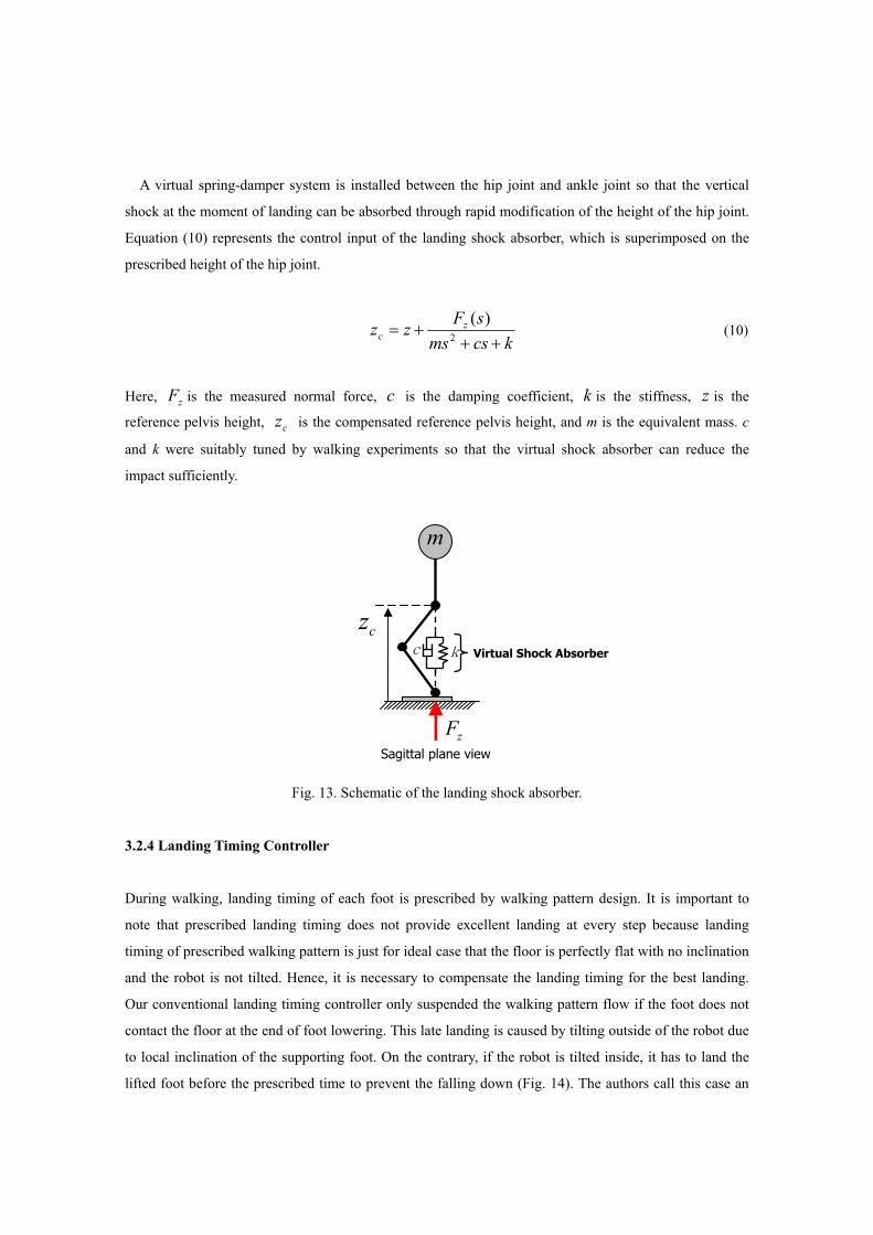
A virtual spring-damper system is installed between the hip joint and ankle joint so that the vertical
shock at the moment of landing can be absorbed through rapid modification of the height of the hip joint.
Equation (10) represents the control input of the landing shock absorber, which is superimposed on the
prescribed height of the hip joint.
kcsmssFzz z
c +++= 2
)( (10)
Here, zF is the measured normal force, c is the damping coefficient, k is the stiffness, z is the
reference pelvis height, cz is the compensated reference pelvis height, and m is the equivalent mass. c
and k were suitably tuned by walking experiments so that the virtual shock absorber can reduce the
impact sufficiently.
Fig. 13. Schematic of the landing shock absorber.
3.2.4 Landing Timing Controller
During walking, landing timing of each foot is prescribed by walking pattern design. It is important to
note that prescribed landing timing does not provide excellent landing at every step because landing
timing of prescribed walking pattern is just for ideal case that the floor is perfectly flat with no inclination
and the robot is not tilted. Hence, it is necessary to compensate the landing timing for the best landing.
Our conventional landing timing controller only suspended the walking pattern flow if the foot does not
contact the floor at the end of foot lowering. This late landing is caused by tilting outside of the robot due
to local inclination of the supporting foot. On the contrary, if the robot is tilted inside, it has to land the
lifted foot before the prescribed time to prevent the falling down (Fig. 14). The authors call this case an
Sagittal plane view
m
Virtual Shock Absorberc k
cz
zF
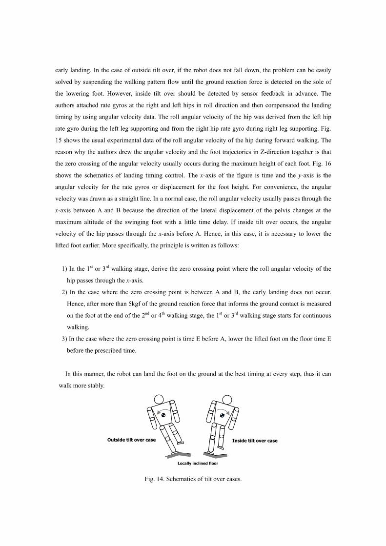
early landing. In the case of outside tilt over, if the robot does not fall down, the problem can be easily
solved by suspending the walking pattern flow until the ground reaction force is detected on the sole of
the lowering foot. However, inside tilt over should be detected by sensor feedback in advance. The
authors attached rate gyros at the right and left hips in roll direction and then compensated the landing
timing by using angular velocity data. The roll angular velocity of the hip was derived from the left hip
rate gyro during the left leg supporting and from the right hip rate gyro during right leg supporting. Fig.
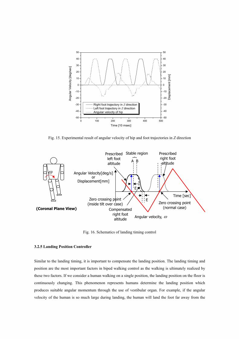
15 shows the usual experimental data of the roll angular velocity of the hip during forward walking. The
reason why the authors drew the angular velocity and the foot trajectories in Z-direction together is that
the zero crossing of the angular velocity usually occurs during the maximum height of each foot. Fig. 16
shows the schematics of landing timing control. The x-axis of the figure is time and the y-axis is the
angular velocity for the rate gyros or displacement for the foot height. For convenience, the angular
velocity was drawn as a straight line. In a normal case, the roll angular velocity usually passes through the
x-axis between A and B because the direction of the lateral displacement of the pelvis changes at the
maximum altitude of the swinging foot with a little time delay. If inside tilt over occurs, the angular
velocity of the hip passes through the x-axis before A. Hence, in this case, it is necessary to lower the
lifted foot earlier. More specifically, the principle is written as follows:
1) In the 1st or 3rd walking stage, derive the zero crossing point where the roll angular velocity of the
hip passes through the x-axis.
2) In the case where the zero crossing point is between A and B, the early landing does not occur.
Hence, after more than 5kgf of the ground reaction force that informs the ground contact is measured
on the foot at the end of the 2nd or 4th walking stage, the 1st or 3rd walking stage starts for continuous
walking.
3) In the case where the zero crossing point is time E before A, lower the lifted foot on the floor time E
before the prescribed time.
In this manner, the robot can land the foot on the ground at the best timing at every step, thus it can
walk more stably.
Fig. 14. Schematics of tilt over cases.
Outside tilt over case Inside tilt over case
Locally inclined floor
0 100 200 300 400 500-50
-40
-30
-20
-10
0
10
20
30
40
50
-50
-40
-30
-20
-10
0
10
20
30
40
50
Dis
plac
emen
t [m
m]
Ang
ular
Vel
ocity
[deg
/sec
]
Time [10 msec]
Right foot trajectory in Z direction Left foot trajectory in Z direction Angular velocity of hip
Fig. 15. Experimental result of angular velocity of hip and foot trajectories in Z direction
Fig. 16. Schematics of landing timing control
3.2.5 Landing Position Controller
Similar to the landing timing, it is important to compensate the landing position. The landing timing and
position are the most important factors in biped walking control as the walking is ultimately realized by
these two factors. If we consider a human walking on a single position, the landing position on the floor is
continuously changing. This phenomenon represents humans determine the landing position which
produces suitable angular momentum through the use of vestibular organ. For example, if the angular
velocity of the human is so much large during landing, the human will land the foot far away from the
(Coronal Plane View)
ω
Prescribedleft foot altitude
Prescribed right foot altitude
Angular velocity, ω
Stable region
EZero crossing point (inside tilt over case)
E
A B
Compensated right foot altitude
Time [sec]
Zero crossing point (normal case)
Angular Velocity[deg/s]or
Displacement[mm]
body center in order to reduce the angular velocity after landing. Likewise, a biped walking robot also has
to compensate the landing position from the prescribed landing position through the sensor feedback. The
authors compensate the landing position before landing by using the angular momentum so that the robot
can land the foot at the suitable position which is predicted to generate moderate angular momentum at
every step. The rate gyro is attached on the hip because the angular velocity signal of the hip is clearer
than that of the torso. Since the frames between the pelvis and leg are flexible and the reduction gears of
the hip joints are compliant, there is a great deal of noise in the angular velocity of the torso. Hence, the
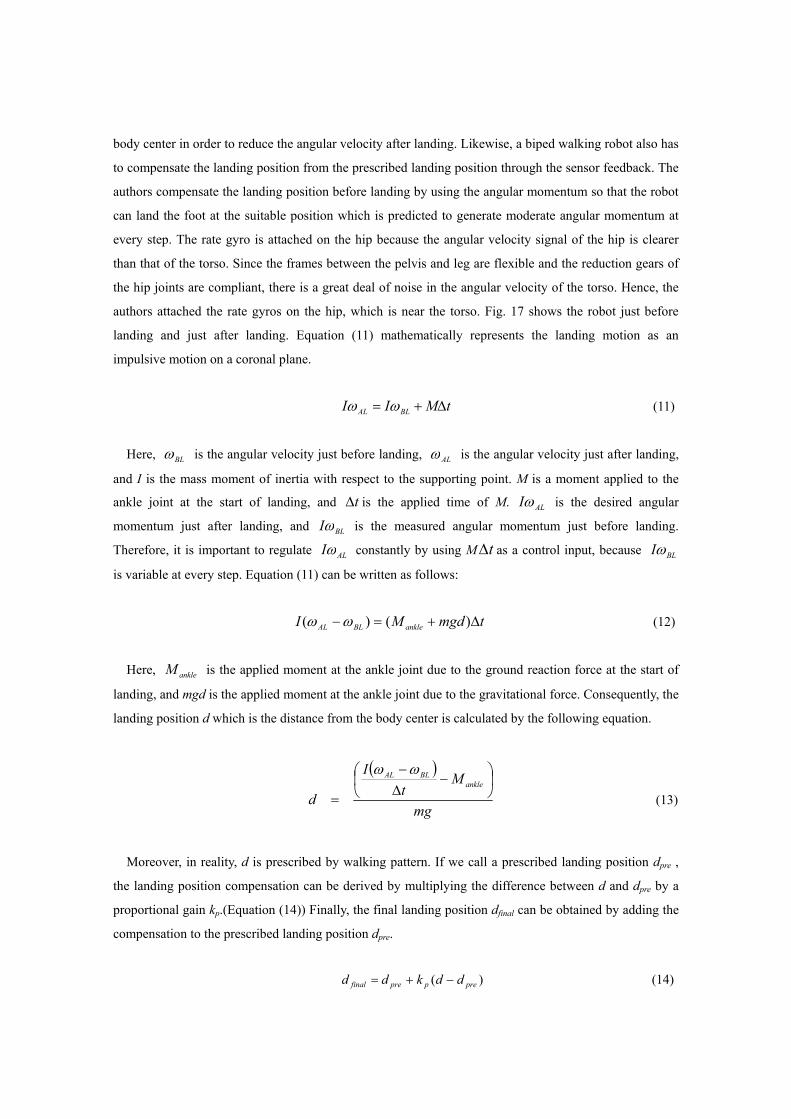
authors attached the rate gyros on the hip, which is near the torso. Fig. 17 shows the robot just before
landing and just after landing. Equation (11) mathematically represents the landing motion as an
impulsive motion on a coronal plane.
tMII BLAL ∆+= ωω (11)
Here, BLω is the angular velocity just before landing, ALω is the angular velocity just after landing,
and I is the mass moment of inertia with respect to the supporting point. M is a moment applied to the
ankle joint at the start of landing, and t∆ is the applied time of M. ALIω is the desired angular
momentum just after landing, and BLIω is the measured angular momentum just before landing.
Therefore, it is important to regulate ALIω constantly by using M t∆ as a control input, because BLIω
is variable at every step. Equation (11) can be written as follows:
tmgdMI ankleBLAL ∆+=− )()( ωω (12)
Here, ankleM is the applied moment at the ankle joint due to the ground reaction force at the start of
landing, and mgd is the applied moment at the ankle joint due to the gravitational force. Consequently, the
landing position d which is the distance from the body center is calculated by the following equation.
( )
mg
Mt
I
dankle
BLAL ⎟⎠⎞
⎜⎝⎛ −
∆−
=
ωω
(13)
Moreover, in reality, d is prescribed by walking pattern. If we call a prescribed landing position dpre ,
the landing position compensation can be derived by multiplying the difference between d and dpre by a
proportional gain kp.(Equation (14)) Finally, the final landing position dfinal can be obtained by adding the
compensation to the prescribed landing position dpre.
)( prepprefinal ddkdd −+= (14)

Fig. 17. The schematics of landing position control
3.2.6 Vibration Reduction Controller
When a biped humanoid robot is walking, the swinging leg vibrates. This is because the connecting frame
between the leg and pelvis is deflecting and the reduction gear is slightly compliant. While the vibrations
are not large, they disturb the precise landing position control of the foot. If the position control accuracy
is not within ± 3 mm, the performance of the landing position controller is diminished. Therefore, the
vibration reduction is fundamentally necessary for the landing position controller, so the authors proposed
the vibration reduction controller in order to reduce the vibrations of foot. Fig. 18 represents a
mathematical model of a swinging leg.
Fig. 18. A simple mathematical model of the leg
In Fig. 18, u is the control input angle of hip joint, θ is the actual angle of hip joint, m is the point
u
m
kθ l
Hip Roll Joint
Supportingleg
Swinging leg
Coronal Plane View
Rolling Vibration
Swinging leg
Supporting leg
Modeling
BLω
t∆Just before landing Just after landing
BLω ALω
M
d
mass of a leg, l is the distance from the hip joint to the mass center, and k is the torsional stiffness of the
spring. The equation of motion of the system is derived as follows:
)(2 ukml −−= θθ&& (15)
Thus, the transfer function is
22
2
)()()(
mlksmlk
sussG
+==
θ (16)
The transfer function shown above is a marginally stable system that has two poles on an imaginary
axis in the Laplace domain. To derive 2mlk , the period of vibration was calculated by free vibration
experiments of the lifted foot in the static single support phase. The exact transfer function of the rolling
joint of the hip joints as determined experimentally is
2.746
2.746)( 2 +=
ssG (17)
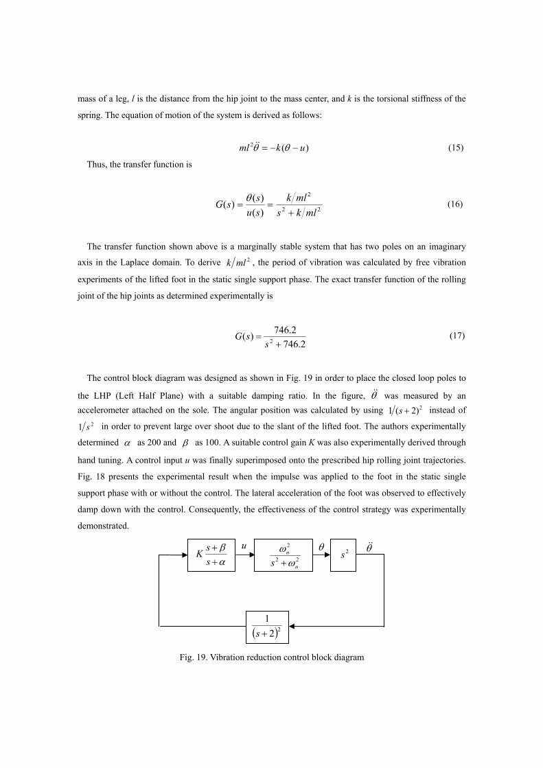
The control block diagram was designed as shown in Fig. 19 in order to place the closed loop poles to
the LHP (Left Half Plane) with a suitable damping ratio. In the figure, θ&& was measured by an accelerometer attached on the sole. The angular position was calculated by using 2)2(1 +s instead of
21 s in order to prevent large over shoot due to the slant of the lifted foot. The authors experimentally
determined α as 200 and β as 100. A suitable control gain K was also experimentally derived through
hand tuning. A control input u was finally superimposed onto the prescribed hip rolling joint trajectories.
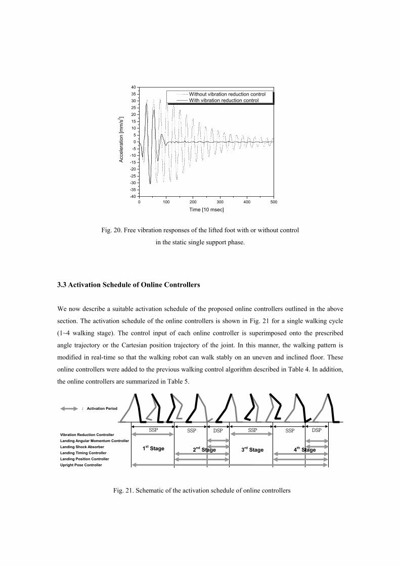
Fig. 18 presents the experimental result when the impulse was applied to the foot in the static single
support phase with or without the control. The lateral acceleration of the foot was observed to effectively
damp down with the control. Consequently, the effectiveness of the control strategy was experimentally
demonstrated.
Fig. 19. Vibration reduction control block diagram
22
2
n
n
s ωω+α
β++
ssK 2s
θ θ&&
( )221+s
u
0 100 200 300 400 500-40-35
-30-25
-20-15
-10-50
510
1520
2530
3540
Acce
lera
tion
[mm
/s2 ]
Time [10 msec]
Without vibration reduction control With vibration reduction control
Fig. 20. Free vibration responses of the lifted foot with or without control
in the static single support phase.
3.3 Activation Schedule of Online Controllers
We now describe a suitable activation schedule of the proposed online controllers outlined in the above
section. The activation schedule of the online controllers is shown in Fig. 21 for a single walking cycle
(1~4 walking stage). The control input of each online controller is superimposed onto the prescribed
angle trajectory or the Cartesian position trajectory of the joint. In this manner, the walking pattern is
modified in real-time so that the walking robot can walk stably on an uneven and inclined floor. These
online controllers were added to the previous walking control algorithm described in Table 4. In addition,
the online controllers are summarized in Table 5.
Fig. 21. Schematic of the activation schedule of online controllers
Vibration Reduction Controller Landing Angular Momentum Controller Landing Shock Absorber Landing Timing Controller Landing Position Controller Upright Pose Controller
SSP DSP SSP DSP SSP SSP
: Activation Period
1st Stage 2nd Stage 3rd Stage 4th Stage
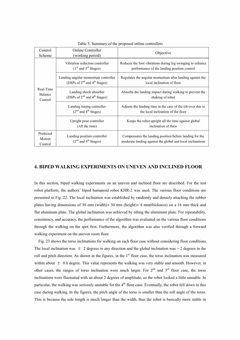
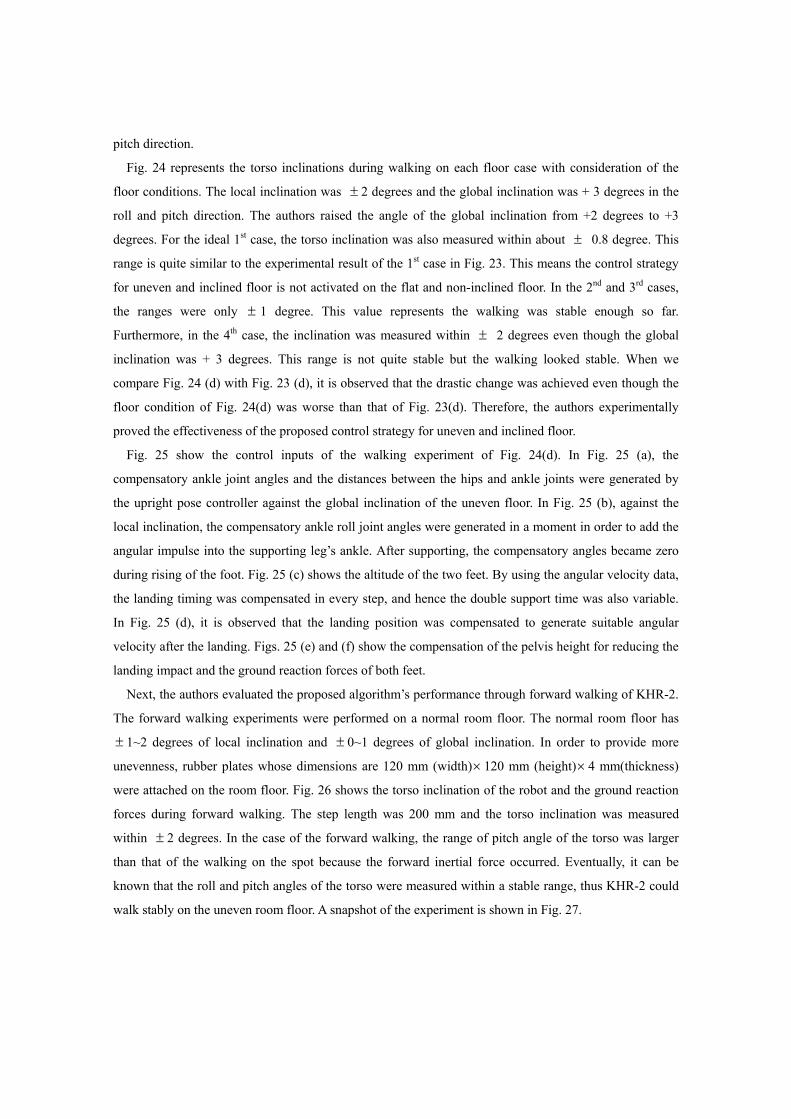
Table 5. Summary of the proposed online controllers Control Scheme
Online Controller (working period) Objective
Vibration reduction controller (1st and 3rd Stages)
Reduces the foot vibrations during leg swinging to enhance performance of the landing position control
Landing angular momentum controller(DSPs of 2nd and 4th Stages)
Regulates the angular momentum after landing against the local inclination of floor
Landing shock absorber (DSPs of 2nd and 4th Stages)
Absorbs the landing impact during walking to prevent the shaking of robot
Landing timing controller (2nd and 4th Stages)
Adjusts the landing time in the case of the tilt-over due to the local inclination of the floor
Real-Time Balance Control
Upright pose controller (All the time)
Keeps the robot upright all the time against global inclination of floor
Predicted Motion Control
Landing position controller (2nd and 4th Stages)
Compensates the landing position before landing for the moderate landing against the global and local inclinations
4. BIPED WALKING EXPERIMENTS ON UNEVEN AND INCLINED FLOOR
In this section, biped walking experiments on an uneven and inclined floor are described. For the test
robot platform, the authors’ biped humanoid robot KHR-2 was used. The various floor conditions are
presented in Fig. 22. The local inclination was established by randomly and densely attaching the rubber
plates having dimensions of 30 mm (width)× 30 mm (height)× 4 mm(thickness) on a 16 mm thick and
flat aluminum plate. The global inclination was achieved by tilting the aluminum plate. For repeatability,
consistency, and accuracy, the performance of the algorithm was evaluated on the various floor conditions
through the walking on the spot first. Furthermore, the algorithm was also verified through a forward
walking experiment on the uneven room floor.
Fig. 23 shows the torso inclinations for walking on each floor case without considering floor conditions.
The local inclination was ± 2 degrees in any direction and the global inclination was + 2 degrees in the
roll and pitch direction. As shown in the figures, in the 1st floor case, the torso inclination was measured
within about ± 0.8 degree. This value represents the walking was very stable and smooth. However, in
other cases, the ranges of torso inclination were much larger. For 2nd and 3rd floor case, the torso
inclinations were fluctuated with an about 2 degrees of amplitude, so the robot looked a little unstable. In
particular, the walking was seriously unstable for the 4th floor case. Eventually, the robot fell down in this
case during walking. In the figures, the pitch angle of the torso is smaller than the roll angle of the torso.
This is because the sole length is much longer than the width, thus the robot is basically more stable in
pitch direction.
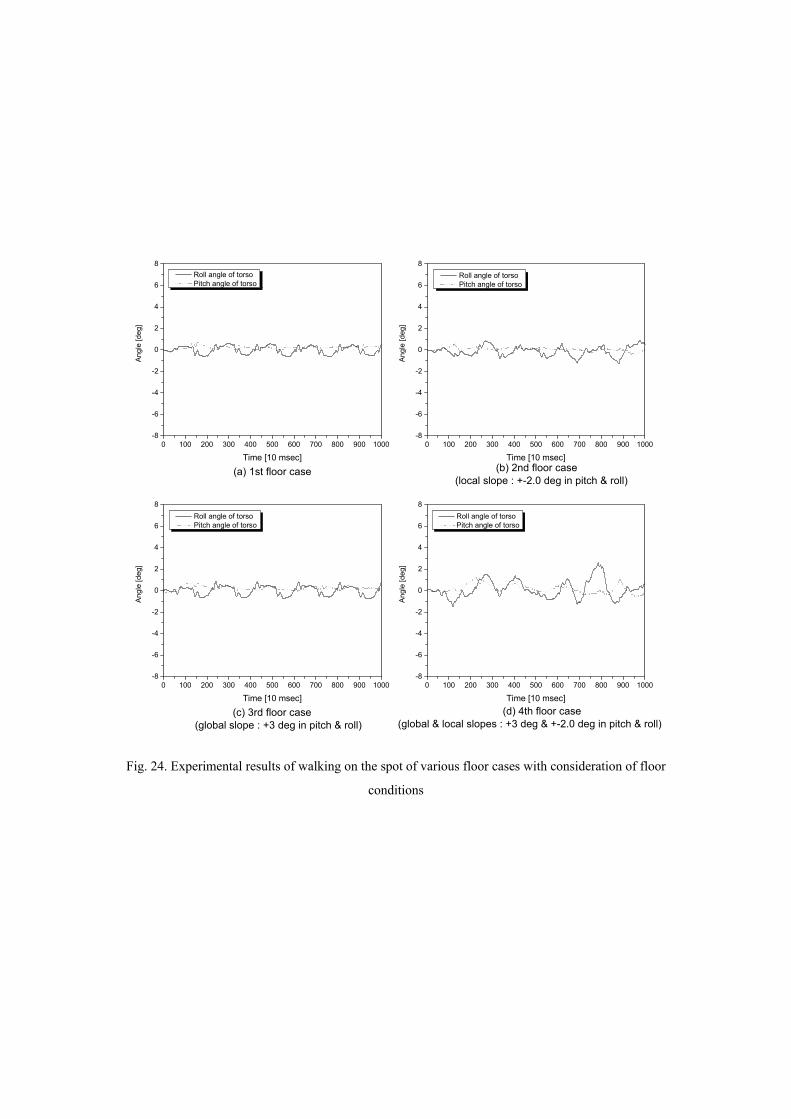
Fig. 24 represents the torso inclinations during walking on each floor case with consideration of the
floor conditions. The local inclination was ± 2 degrees and the global inclination was + 3 degrees in the
roll and pitch direction. The authors raised the angle of the global inclination from +2 degrees to +3
degrees. For the ideal 1st case, the torso inclination was also measured within about ± 0.8 degree. This
range is quite similar to the experimental result of the 1st case in Fig. 23. This means the control strategy
for uneven and inclined floor is not activated on the flat and non-inclined floor. In the 2nd and 3rd cases,
the ranges were only ± 1 degree. This value represents the walking was stable enough so far.
Furthermore, in the 4th case, the inclination was measured within ± 2 degrees even though the global
inclination was + 3 degrees. This range is not quite stable but the walking looked stable. When we
compare Fig. 24 (d) with Fig. 23 (d), it is observed that the drastic change was achieved even though the
floor condition of Fig. 24(d) was worse than that of Fig. 23(d). Therefore, the authors experimentally
proved the effectiveness of the proposed control strategy for uneven and inclined floor.
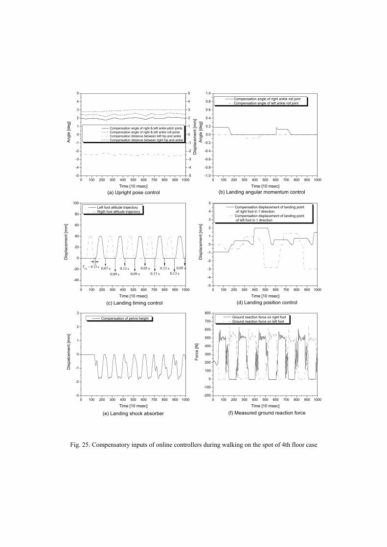
Fig. 25 show the control inputs of the walking experiment of Fig. 24(d). In Fig. 25 (a), the
compensatory ankle joint angles and the distances between the hips and ankle joints were generated by
the upright pose controller against the global inclination of the uneven floor. In Fig. 25 (b), against the
local inclination, the compensatory ankle roll joint angles were generated in a moment in order to add the
angular impulse into the supporting leg’s ankle. After supporting, the compensatory angles became zero
during rising of the foot. Fig. 25 (c) shows the altitude of the two feet. By using the angular velocity data,
the landing timing was compensated in every step, and hence the double support time was also variable.
In Fig. 25 (d), it is observed that the landing position was compensated to generate suitable angular
velocity after the landing. Figs. 25 (e) and (f) show the compensation of the pelvis height for reducing the
landing impact and the ground reaction forces of both feet.
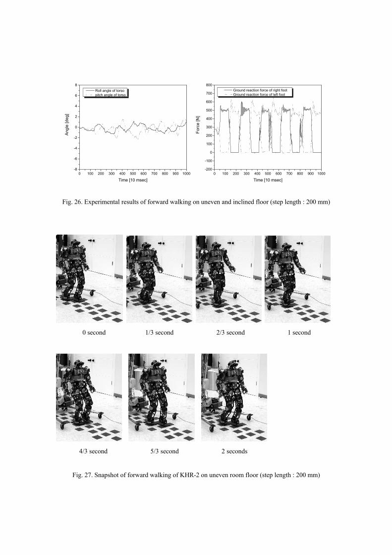
Next, the authors evaluated the proposed algorithm’s performance through forward walking of KHR-2.
The forward walking experiments were performed on a normal room floor. The normal room floor has
± 1~2 degrees of local inclination and ± 0~1 degrees of global inclination. In order to provide more
unevenness, rubber plates whose dimensions are 120 mm (width)× 120 mm (height)× 4 mm(thickness)
were attached on the room floor. Fig. 26 shows the torso inclination of the robot and the ground reaction
forces during forward walking. The step length was 200 mm and the torso inclination was measured
within ± 2 degrees. In the case of the forward walking, the range of pitch angle of the torso was larger
than that of the walking on the spot because the forward inertial force occurred. Eventually, it can be
known that the roll and pitch angles of the torso were measured within a stable range, thus KHR-2 could
walk stably on the uneven room floor. A snapshot of the experiment is shown in Fig. 27.
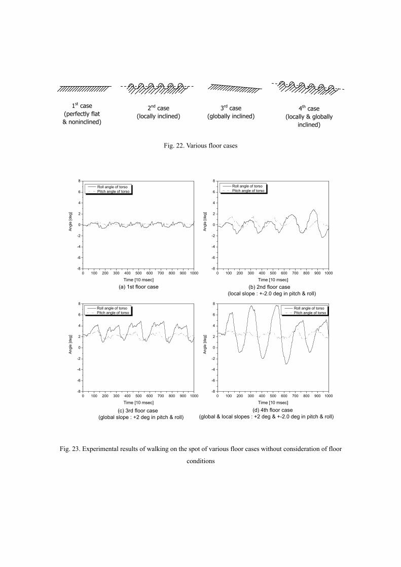
Fig. 22. Various floor cases
0 100 200 300 400 500 600 700 800 900 1000-8
-6
-4
-2
0
2
4
6
8
0 100 200 300 400 500 600 700 800 900 1000-8
-6
-4
-2
0
2
4
6
8
0 100 200 300 400 500 600 700 800 900 1000-8
-6
-4
-2
0
2
4
6
8
0 100 200 300 400 500 600 700 800 900 1000-8
-6
-4
-2
0
2
4
6
8
(d) 4th floor case (global & local slopes : +2 deg & +-2.0 deg in pitch & roll)
(c) 3rd floor case (global slope : +2 deg in pitch & roll)
(b) 2nd floor case (local slope : +-2.0 deg in pitch & roll)
Ang
le [d
eg]
Time [10 msec]
Roll angle of torso Pitch angle of torso
(a) 1st floor case
Ang
le [d
eg]
Time [10 msec]
Roll angle of torso Pitch angle of torso
Ang
le [d
eg]
Time [10 msec]
Roll angle of torso Pitch angle of torso
Ang
le [d
eg]
Time [10 msec]
Roll angle of torso Pitch angle of torso
Fig. 23. Experimental results of walking on the spot of various floor cases without consideration of floor
conditions
1st case (perfectly flat & noninclined)
2nd case (locally inclined)
3rd case (globally inclined)
4th case (locally & globally
inclined)
0 100 200 300 400 500 600 700 800 900 1000-8
-6
-4
-2
0
2
4
6
8
0 100 200 300 400 500 600 700 800 900 1000-8
-6
-4
-2
0
2
4
6
8
0 100 200 300 400 500 600 700 800 900 1000-8
-6
-4
-2
0
2
4
6
8
0 100 200 300 400 500 600 700 800 900 1000-8
-6
-4
-2
0
2
4
6
8
Ang
le [d
eg]
Time [10 msec]
Roll angle of torso Pitch angle of torso
Ang
le [d
eg]
Time [10 msec]
Roll angle of torso Pitch angle of torso
Ang
le [d
eg]
Time [10 msec]
Roll angle of torso Pitch angle of torso
(d) 4th floor case (global & local slopes : +3 deg & +-2.0 deg in pitch & roll)
(c) 3rd floor case (global slope : +3 deg in pitch & roll)
(b) 2nd floor case (local slope : +-2.0 deg in pitch & roll)
(a) 1st floor case
Ang
le [d
eg]
Time [10 msec]
Roll angle of torso Pitch angle of torso
Fig. 24. Experimental results of walking on the spot of various floor cases with consideration of floor
conditions
0 100 200 300 400 500 600 700 800 900 1000-5
-4
-3
-2
-1
0
1
2
3
4
5
-5
-4
-3
-2
-1
0
1
2
3
4
5
0 100 200 300 400 500 600 700 800 900 1000-1.0
-0.8
-0.6
-0.4
-0.2
0.0
0.2
0.4
0.6
0.8
1.0
0 100 200 300 400 500 600 700 800 900 1000
-40
-20
0
20
40
60
80
100
0 100 200 300 400 500 600 700 800 900 1000-5
-4
-3
-2
-1
0
1
2
3
4
5
0 100 200 300 400 500 600 700 800 900 1000-3
-2
-1
0
1
2
3
0 100 200 300 400 500 600 700 800 900 1000-200
-100
0
100
200
300
400
500
600
700
800
(f) Measured ground reaction force(e) Landing shock absorber
(d) Landing position control(c) Landing timing control
(b) Landing angular momentum control(a) Upright pose control D
ispl
acem
ent [
mm
]
Ang
le [d
eg]
Time [10 msec]
Compensation angle of right & left ankle pitch joints Compensation angle of right & left ankle roll joints Compensation distance between left hip and ankle Compensation distance between right hip and ankle
Ang
le [d
eg]
Time [10 msec]
Compensation angle of right ankle roll joint Compensation angle of left ankle roll joint
0.05 s0.13 s
0.13 s0.13 s
0.05 s0.09 s
0.13 s0.09 s
0.07 s
Dis
plac
emen
t [m
m]
Time [10 msec]
Left foot altitude trajectory Rigth foot altitude trajectory
Tdsp = 0.13 s
D
ispl
acem
ent [
mm
]
Time [10 msec]
Compensation displacement of landing point of right foot in Y direction
Compensation displacement of landing point of left foot in Y direction
Dis
palc
emen
t [m
m]
Time [10 msec]
Compensation of pelvis height
Forc
e [N
]
Time [10 msec]
Ground reaction force on right foot Ground reaction force on left foot
Fig. 25. Compensatory inputs of online controllers during walking on the spot of 4th floor case
0 100 200 300 400 500 600 700 800 900 1000-8
-6
-4
-2
0
2
4
6
8
0 100 200 300 400 500 600 700 800 900 1000-200
-100
0
100
200
300
400
500
600
700
800
Ang
le [d
eg]
Time [10 msec]
Roll angle of torso pitch angle of torso
Forc
e [N
]
Time [10 msec]
Ground reaction force of right foot Ground reaction force of left foot
Fig. 26. Experimental results of forward walking on uneven and inclined floor (step length : 200 mm)
0 second 1/3 second 2/3 second 1 second
4/3 second 5/3 second 2 seconds
Fig. 27. Snapshot of forward walking of KHR-2 on uneven room floor (step length : 200 mm)
5. CONCLUSION AND FUTURE WORK
This paper described a walking control algorithm for biped humanoid robots that considers an uneven and
inclined floor. In the case of the author’s previous algorithm, the online controllers were designed without
the consideration of the local and global inclinations of the floor. That is, the floor was assumed to be
comparatively flat. The previous online controllers worked well for a slightly uneven and inclined floor,
but the robot immediately fell down when the floor inclinations exceeded a certain threshold. Hence, six
online controllers (Upright pose controller, landing angular momentum controller, landing shock absorber,
landing timing controller, landing position controller, and vibration reduction controller) were developed
and added to the previous algorithm. These online controllers were designed through simple mathematical
models and experiments, and then suitable activation periods were planned in a walking cycle. Each
online controller has a clear objective and the controllers are decoupled from each other. To validate the
performance of the online controllers, walking experiments on an uneven and inclined aluminum plate
were performed. After stable walking on the aluminum plate was confirmed, a forward walking
experiment on an uneven room floor was carried out. Successful forward walking was realized, and the
effectiveness of the proposed walking algorithm was thereby verified.
As future research, it is necessary to develop a more human-like sole that is ground shape adaptive and
ground reaction force absorptive. In the case of a human sole, the thick and soft skin absorbs landing
impact and adapts to uneven ground. The authors’ biped humanoid robots, KHR-2, HUBO, and Albert
HUBO have hard and flat soles with four rubber supporters. If the floor’s curvature is large, one rubber
supporter among the four rubber supporters may not be in contact with the floor, and consequently the
foot landing becomes unstable. In addition, structural vibrations of the sole are generated because it is
hard and has little damping property. From this point of view, it is necessary to attach damping systems
that have a good force of restitution on the hard aluminum sole.
ACKNOWLEDGEMENTS
This research was supported by the MOCIE (Ministry of Commerce, Industry and Energy) of South
Korea.
REFERENCES
1. J. Yamaguchi, A. Takanishi, I. Kato.: Development of a biped walking robot compensating for three-
axis moment by trunk motion. Paper presented at the IEEE/RSJ international conference on intelligent
robots and systems, Yokohama, Japan, 26-30 July 1993
2. K. Nagasaka, H. Inoue, M. Inaba. : Dynamic walking pattern generation for a humanoid robot based on
optimal gradient method. Paper presented at the IEEE international conference on systems, man, and
cybernetics, 12-15 Oct. 1999
3. Y. Sakagami, R. Watanabe, C. Aoyama, S. Matsunaga, N. Higaki, K. Fujimura.: The intelligent
ASIMO: System overview and integration. Paper presented at the IEEE/RSJ international conference on
intelligent robots and systems, Lausanne, Switzerland, 30 Sep.- 5 Oct. 2002
4. K. Kaneko, F. Kanehiro, S. Kajita, H. Hirukawa, T. Kawasaki, M. Hirata, K. Akachi, T. Isozumi.:
Humanoid robot HRP-2. Paper presented at IEEE international conference on robotics and automation,
New Orieans, LA, 26 April - 1 May 2004
5. W. T. Miller III.: Real-time neural network control of a biped walking robot. IEEE Control Systems
Magazine. 14(1): 41-48 (1994)
6. C. L. Shih.: Ascending and descending stairs for a biped robot. IEEE Transactions on Systems, Man
and Cybernetics. 29(3): 255-268 (1999)
7. J. Yamaguchi, E. Soga, S. Inoue, A. Takanishi.: Development of a bipedal humanoid robot – control
method of whole body cooperative dynamic biped walking-. Paper presented at the IEEE international
conference on robotics and automation, Detroit, Michigan, 10-15 May 1999
8. K. Hirai, M. Hirose, T. Takenaka.: The development of Honda humanoid robot. Paper presented at the
IEEE international conference on robotics and automation, Leuven, Belgium, 16-20 May 1998
9. S. Kajita, F. Kanehiro, K. Kaneko, K. Fujiwara, K. Harada, K. Yokoi, H. Hirukawa.: Biped walking
pattern generation by using preview control of Zero-Moment Point. Paper presented at the IEEE
international conference on robotics and automation, Taipei, Taiwan, 14-19 Sep. 2003
10. M.Vukobratovic, B. Borovac, D. Surla, D. Stokic.: Biped locomotion. Springer-Verlag (1990)
11. K. Nishiwaki, S. Kagami, Y. Kuniyoshi, M. Inaba, H. Inoue.: Online generation of humanoid walking
motion based on fast generation method of motion pattern that follows desired ZMP. Paper presented at
the IEEE/RSJ international conference on intelligent robots and systems, Lausanne, Switzerland, 30 Sep.
– 5 Oct. 2002
12. J. H. Kim, J. H. Oh.: Walking control of the humanoid platform KHR-1 based on torque feedback
control. Paper presented at the IEEE international conference on robotics and automation, New Orieans,
LA, 26 April - 1 May 2004
13. J. Y. Kim, I. W. Park, J. H. Oh.: Experimental realization of dynamic walking of the biped humanoid
robot KHR-2 using zero moment point feedback and inertial measurement. Advanced Robotics. 20(6):
707-736 (2006)
14. Y. Sugahara, T. Hosobata, Y. Mikuriya, H. O. Lim, A. Takanishi.: Realization of stable dynamic
walking by a parallel bipedal locomotor on uneven terrain using a virtual compliance control. Paper
presented at the IEEE/RSJ international conference on intelligent robots and systems, Las Vegas, Nevada,
27-31 Oct. 2003
15. K. Hashimoto, Y. Sugahara, H. O. Lim, A. Takanishi.: Realization of stable walking on public road
with new biped foot system adaptable to uneven terrain. Paper presented at the IEEE/RAS-EMBS
international conference on biomedical robotics and biomechatronics, 20-22 Feb. 2006
16. I. W. Park, J. Y. Kim, J. Lee, J. H. Oh.: Mechanical design of humanoid robot platform KHR-
3(KAIST Humanoid Robot-3:HUBO). Paper presented at the IEEE/RAS international conference on
humanoid robots, Tsukuba, Japan, 5-7 Dec. 2005
17. V. T. Inman, H. J. Ralston and F. Todd, Human Walking, London : Williams & Wilkins, 1981.