vwr water jacketed co2 incubators with microprocessor control
TRANSCRIPT

WATER JACKETED CO2 INCUBATORS
WITH MICROPROCESSOR CONTROL
MODEL: 2310, 2300, 2350 2400, 2450
INSTALLATION AND OPERATION MANUAL
Sheldon Manufacturing Inc. P.O. Box 627 Cornelius, Oregon 97113 EMAIL: [email protected] INTERNET: http://www.Shellab.com/~Shellab
1-800-322-4897 (503) 640-3000 FAX (503) 640-1366
3
TABLE OF CONTENTS SECTION 1.0 RECEIVING AND INSPECTION SECTION 2.0 GRAPHIC SYMBOLS SECTION 3.0 INSTALLATION SECTION 4.0 CONTROL PANEL OVERVIEW SECTION 5.0 OPERATION SECTION 6.0 FYRITE CO2 CHECKING SECTION 7.0 MAINTENANCE SECTION 8.0 TROUBLESHOOTING SECTION 9.0 PARTS LIST UNIT SPECIFICATION SCHEMATICS
REV 02/07 4861519
These units are CO2 Water Jacketed incubators for professional, industrial or educational use where the preparation or testing of materials is done at approximately atmospheric pressure and no flammable, volatile, or combustible materials are being heated. These units are not intended for hazardous or household locations or use.
INTRODUCTION Thank you for choosing a water jacket incubator. These units are not intended for use at hazardous or household locations. Before you use the unit, read this entire manual carefully to understand how to install, operate, and maintain the unit in a safe manner. Your satisfaction with the unit will be maximized as you read about its safety and operational features. Keep this manual on-hand so it can be used by all operators of the unit. Be sure all operators of the unit are given appropriate training before you put the unit in service.
Note: Use the unit only in the way described in this manual. Failure to follow the guidelines and instructions in this manual may be dangerous and illegal.
General Safety Considerations Your incubator and its recommended accessories have been designed and tested to meet strict safety requirements. For continued safe operation of your incubator, always follow basic safety precautions including:
• Read this entire manual before using the incubator.
• Be sure you follow any city, county, or other ordinances in your area regarding the use of this unit.
• Use only approved accessories. Do not modify system components. Any alterations or modifications to your incubator may be dangerous and will void your warranty.
• Always plug the unit’s power cord into a grounded electrical outlet that conforms to national and local electrical codes. If the unit is not grounded, parts such as knobs and controls may conduct electricity and cause serious injury.
• Do not connect the unit to a power source of any other voltage or frequency beyond the range stated on the power rating on the dataplate inside the door of the unit.
• Do not modify the power cord provided with the unit. If the plug does not fit an outlet, have a proper outlet installed by a qualified electrician.
• Avoid damaging the power cord. Do not bend it excessively, step on it, place heavy objects on it. A damaged cord can easily become a shock or fire hazard. Never use a power cord after it has become damaged.
• Do not position the equipment in such a manner as to make it difficult to disconnect power cord or coupler.
• Do not attempt to move the unit while in operation or before the unit has been allowed to cool.
3
RECEIVING AND INSPECTION IMPORTANT: READ THIS INSTRUCTION MANUAL IMMEDIATELY. Your satisfaction and safety require a complete understanding of this unit, including its proper function and operational characteristics. Be sure operators are given adequate training before attempting to put the unit in service. NOTE: This equipment must be used only for its intended application; any alterations or modifications will void your warranty. 1.1 Inspection: The carrier, when accepting shipment, also accepts responsibility for
safe delivery and is liable for loss or damage claims. On delivery, inspect for visible exterior damage, note and describe on the freight bill any damage found and enter your claim on the form supplied by the carrier.
1.2 Inspect for concealed loss or damage on the unit itself, both interior and exterior. If
any, the carrier will arrange for official inspection to substantiate your claim. Save the shipping crate until you are sure the unit has been delivered in good condition.
1.3 Return Shipment: If for any reason you must return the unit, contact your
customer service representative for authorization and supply nameplate data. Please see the manual cover for information on where to contact customer service.
1.4 Accessories: Make sure all of the equipment indicated on the packing slip is
included with the unit. Carefully check all packaging before discarding. An accessory package is included with each unit. The 2310 comes equipped with 3 shelves, 4 shelf standards, 4 leveling feet, 1 humidity pan, and supply hose kit. The 2300 and 2400 comes equipped with 3 shelves, 2 shelf stands and 1 humidity pan per chamber, 4 leveling feet and 1 supply hose kit. All units are supplied with a power cord.
Section
1

4
GRAPHIC SYMBOLS Your incubator has been provided with a display of graphic symbols, which are designed to help in identifying the use and function of the available user adjustable components. 2.1 Indicates that you should consult your manual for further description
or discussion of a control user item. 2.2 Indicates "Temperature". 2.3 Indicates "Overtemperature Safety". 2.4 °C Indicates "Degrees Centigrade". 2.5 CO2 Indicates "Carbon Dioxide". 2.6 Indicates "Gas" (CO2 for this unit). 2.7 Indicates "AC Power ON". 2.8 Indicates "ON/I" and "OFF/O". 2.9 Indicates "Potential Shock Hazard" behind this protective partition. 2.10 Indicates "Protective Earth Ground". 2.11 Indicates "Water Jacket Low".
2.12 Indicates “Unit should be recycled” (Not disposed of in land-fill)
Section
2

5
INSTALLATION Local city, county, or other ordinances may govern the use of this equipment. If you have any questions about local requirements, please contact the appropriate local agency. Installation may be performed by the end user. Under normal circumstances this unit is intended for use indoors, at room temperatures between 5° and 40°C , at no greater than 80% Relative Humidity (at 25°C) and with a supply voltage that does not vary by more than 10%. Customer services should be contacted for operating conditions outside of these limits. CAUTION: Make sure that the incubator is located in its intended position and level before filling the water jacket. 3.1 Power Source: The unit power requirements are listed on the data plate. PLUG
THE UNIT INTO A PROPERLY GROUNDED AND RATED RECEPTACLE OF THE CORRECT STYLE. A separate circuit is recommended for this unit to prevent loss of product due to overloading or circuit failures caused by other equipment. The power supply must be properly grounded (earthed) and correctly sized to match the unit nameplate rating. The supply voltage must match the nameplate voltage within +/- 10%. The US market units are designed for 110 volts @ 60 Hz, 5 Amps. The EU market units are designed for 220 volts @ 50 Hz, 3.5 Amps. If supplied with a detachable cord set, plug the female end into the inlet on the unit and the male plug into the supply. Assure that units requiring fuses have them installed. This fuse may be at the inlet or a part of the cord set male plug. The unit must be located to easily allow for it to be unplugged or disconnected.
3.2 Location: When selecting a site for the unit, consider conditions which may affect
performance, such as heat from steam radiators, ovens, autoclaves, etc. Avoid direct sun, fast-moving air currents, heating/cooling ducts, and high-traffic areas. To ensure air circulation around the unit, allow a minimum of 10cm between the incubator and walls or partitions which might obstruct free airflow.
3.3 Lifting/Handling: These units are heavy and care should be taken to use
appropriate lifting devices that are sufficiently rated for these loads. Units should only be lifted from their bottom surfaces. Doors, handles and knobs are not adequate for lifting or transport. All moving parts, such as shelves and trays should be removed and doors need to be positively locked in the closed position during transfer to prevent shifting and damage.
Section
3
6
3.4 Leveling: The unit must sit level and solidly. Leveling feet are supplied and must be installed in the four holes in the bottom corners of the unit. With the feet installed and the unit standing upright, each foot can be raised by turning it in a counterclockwise direction. Adjust the foot at each corner until the unit stands level and solid without rocking. If the unit must be moved, drain all the water from the jacket and turn the leveling feet all the way clockwise to prevent damage.
3.5 Cleaning: The unit chamber should be cleaned and disinfected prior to use.
Your operating conditions and appropriate protocol will determine the correct procedure for decontamination. A typical decontamination procedure that is adequate for many situations has been described below. As well, certain steps are listed that will help reduce the likelihood of contamination and the necessity of decontamination. Whatever process is appropriate, it needs to be done on a regularly scheduled basis. Depending on usage and protocol, this may be monthly, quarterly or otherwise. Regardless of the decontamination procedure used, certain precautions will need to be taken:
A. Always disconnect the unit from the electrical service when cleaning.
Assure all volatile or flammable cleaners are evaporated and dry before reconnecting the unit to the power supply.
B. Special care should be taken when cleaning around sensing heads to
prevent damage.
C. If you use chlorine-based bleaches or abrasive cleaners this will modify the stainless steel interior finish. DO NOT USE hard tools such as metal wire brushes or steel wool. Use non-abrasive cleaners and soft tools such as plastic brushes.
D. In the event hazardous material is spilled onto or into the equipment,
appropriate decontamination must be carried out. If there is any doubt about the compatibility of decontamination or cleaning agents with parts of the equipment or with material contained, please contact the manufacturer or his agent. No decontamination or cleaning agents should be used which could cause a hazard as a result of a reaction with parts of the equipment or with the material contained in it.
TYPICAL DECONTAMINATION PROCEDURE
1. Remove the humidity pan every week and autoclave, or wash with soap
and water then disinfect with 70% alcohol solution. Replace water in the incubator with fresh, DISTILLED water.
2. Flush the sample port tubing with 70% alcohol solution. Replace any lines
that have a green color.
3. Remove the door gaskets, clean and disinfect. Clean and disinfect all

7
mounting grooves for the door gaskets.
4. Remove all shelves, shelf supports, shelf standards and shields. Autoclave, or wash and disinfect as described in item 1.
5. Wash and disinfect all interior surfaces.
6. Give special attention to cleaning and disinfecting all access ports, air
bleeds, shaft holes, electrical pass-through and any other passages into the chamber.
7. Replace all air and CO2 filters every six months or when noticeably dirty
on the upstream side. CO2 filters are located in the shadow box just behind the GAS IN fitting and in line with the CO2 tubing kit. Units with flow meters require operator- supplied air pumps. These pumps should be checked for proper air filtering.
OPERATION FOR MINIMIZING CONTAMINATION
1. Keep the outside of the incubator, including the air in the laboratory, as
clean as possible. This is particularly important for units placed directly on the floor. Do not place incubators near doors, air vents or other areas of high air movement or traffic.
2. The floor around the unit needs to be clean. Units that are placed on the
floor should be mounted higher – typically on a caster platform – for ease of moving the unit during cleaning and access to the back of the unit.
3. Minimize the number of times access is made to the chamber during
normal operation.
4. Do not depend on the use of antibiotics to maintain uncontaminated conditions, as this is an inadequate technique for sterilization. Preferably use aseptic techniques as described above for maintaining sterile conditions in the incubator.
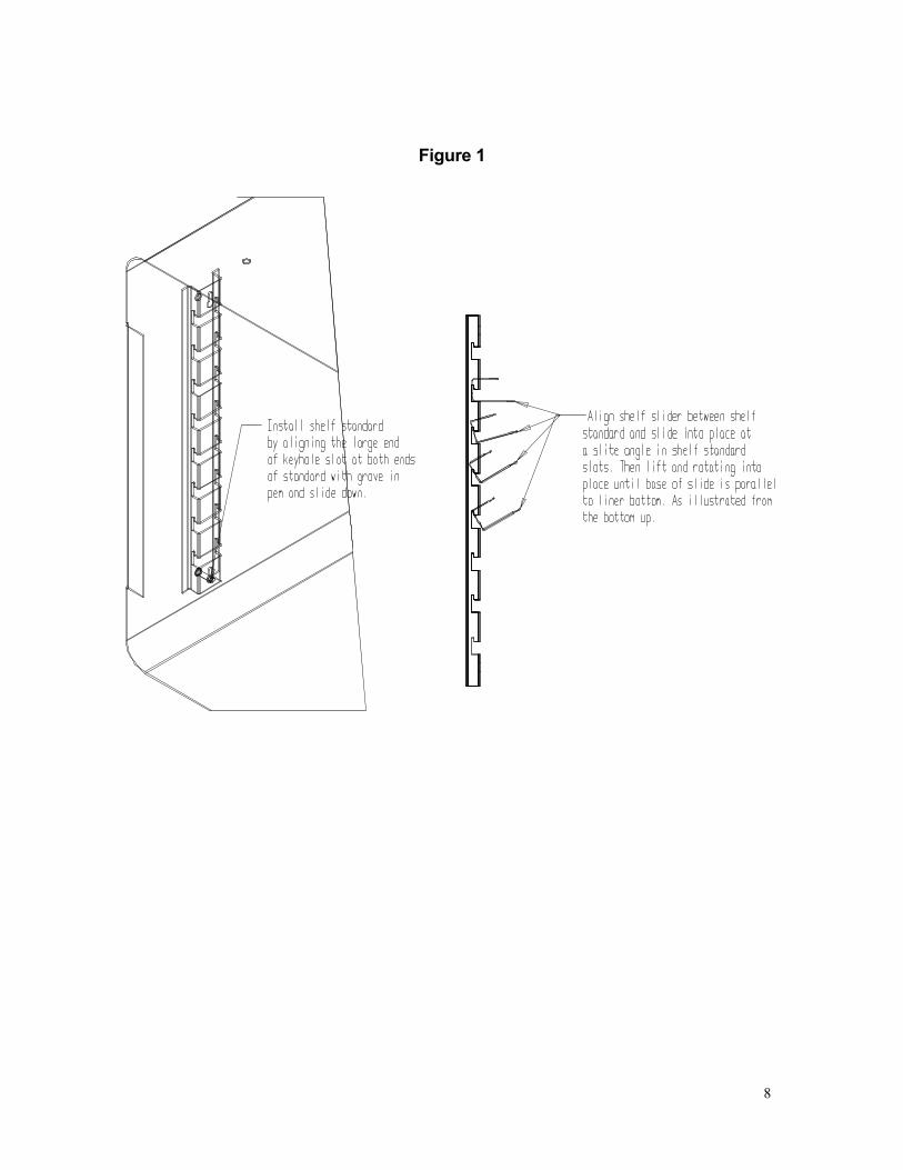
3.6 Shelves and Interior Parts: Shelving, clips and a humidity pan are supplied with
each unit. See Figure 1 for proper placement of these accessories. Also see similar shelf assembly instructions sent with the accessory kit.
8
Figure 1
9
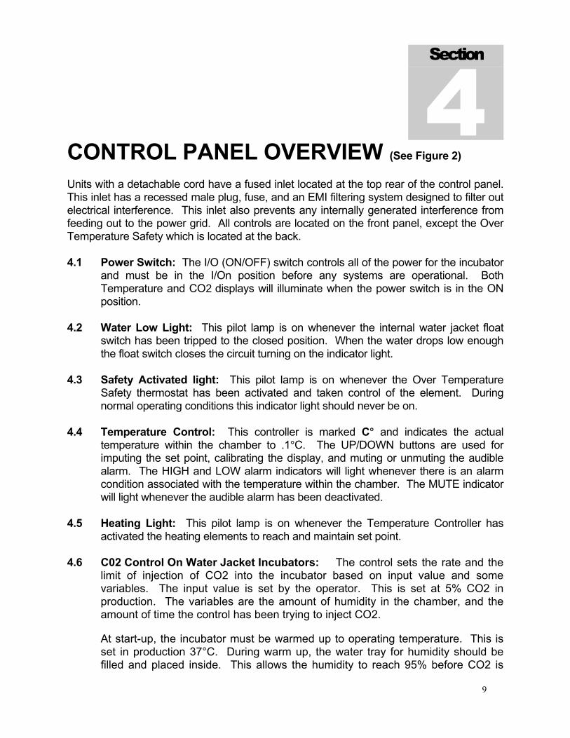
CONTROL PANEL OVERVIEW (See Figure 2) Units with a detachable cord have a fused inlet located at the top rear of the control panel. This inlet has a recessed male plug, fuse, and an EMI filtering system designed to filter out electrical interference. This inlet also prevents any internally generated interference from feeding out to the power grid. All controls are located on the front panel, except the Over Temperature Safety which is located at the back. 4.1 Power Switch: The I/O (ON/OFF) switch controls all of the power for the incubator
and must be in the I/On position before any systems are operational. Both Temperature and CO2 displays will illuminate when the power switch is in the ON position.
4.2 Water Low Light: This pilot lamp is on whenever the internal water jacket float
switch has been tripped to the closed position. When the water drops low enough the float switch closes the circuit turning on the indicator light.
4.3 Safety Activated light: This pilot lamp is on whenever the Over Temperature
Safety thermostat has been activated and taken control of the element. During normal operating conditions this indicator light should never be on.
4.4 Temperature Control: This controller is marked C° and indicates the actual
temperature within the chamber to .1°C. The UP/DOWN buttons are used for imputing the set point, calibrating the display, and muting or unmuting the audible alarm. The HIGH and LOW alarm indicators will light whenever there is an alarm condition associated with the temperature within the chamber. The MUTE indicator will light whenever the audible alarm has been deactivated.
4.5 Heating Light: This pilot lamp is on whenever the Temperature Controller has
activated the heating elements to reach and maintain set point. 4.6 C02 Control On Water Jacket Incubators: The control sets the rate and the
limit of injection of CO2 into the incubator based on input value and some variables. The input value is set by the operator. This is set at 5% CO2 in production. The variables are the amount of humidity in the chamber, and the amount of time the control has been trying to inject CO2.
At start-up, the incubator must be warmed up to operating temperature. This is set in production 37°C. During warm up, the water tray for humidity should be filled and placed inside. This allows the humidity to reach 95% before CO2 is
Section
4
10
injected. The TC type CO2 sensor required 95% humidity to correctly measure the CO2 levels.
The CO2 should be turned OFF during warm up. Failure to do so will cause the control overshoot the set value input by the operator, the injection value can be reset by going into cal mode on the main and door temperatures and back out of cal mode. The unit is then turned off for ten seconds and back on. This rebooting of the incubator control resets the injection rate and limit values to that which was input by the operator. The unit would be then be reset to the selected temperature on main and the door and the CO2 set to the desired level.
4.7 Injection Light: This pilot lamp is on whenever the CO2 controller is injecting the
CO2 into the chamber. 4.8 Over Temperature Safety Control (OTP): Located at the back of the control panel
adjacent to the power inlet. This is a hydraulic thermostat that is wired between the Main Temperature Control and the heating element and functions as an override control. If at any time the Temperature Control fails in the ON position and the temperature in the chamber rises above its set point, the OTP is activated and maintains temperature at its own set point. Note that the HEATING indicator will continue to function under the control of the OTP. It is not recommended that the unit be allowed to operate for an extended period of time using only OTP as temperature uniformity will suffer.
4.9 CO2 Sample Port: This is located in the upper front corner of the right side of the
incubator. A sample can be drawn to measure the CO2 content in the chamber at this port.
Figure 2
11
OPERATION READ THIS SECTION IN ITS ENTIRETY BEFORE ATTEMPTING OPERATION IMPORTANT: In order to assure the proper operation of this incubator, it is essential that you regularly verify the accuracy of the temperature and CO2 controls. Temperature can be confirmed by use of a thermometer inside of the chamber. CO2 can be confirmed with the use of a FYRITE Gas Analyzer or other equipment such as a gas chromatograph. These must be checked at least on a weekly basis. Any questions should be directed to a technical service representative. The temperature, and CO2 were calibrated at the factory prior to shipment. 5.1 Power up the unit by attaching the cord set (supplied with the accessories) to the
unit inlet and the building power supply. Attach the female end of the cordset into the fused and recessed male plug on the rear of the unit and the male plug end of the cord set into the building supply receptacle. Turn the power switch to the I/ON position.
5.2 Filling and Draining the Jacket: The front panel of the incubator has a WATER
LOW warning light. Fill the water jacket with WATER by means of the fill port located at the top right rear of the unit marked FILL WJ HERE. Stop filling when the WATER LOW warning light goes off. When full, the 2310 holds approximately 9.5 U.S. gallons (35.96 Liters) and 19.0 U.S. gallons (72 Liters) for the 2300/2400 chambers. To drain the unit, hook a suitable hose to the siphon tube located to the left of the fill port and marked SIPHON HERE. Start a siphon and allow the water to empty into a suitable service drain or catchment area.
WATER RECOMMENDATIONS FOR USE IN WATER JACKET INCUBATORS The addition of a dis-similar metal anode in Water Jacket incubators will allow the use of good-quality tap water to fill the Jacket. The anode is located in a threaded port near the fill port on the rear of the unit. (diagram). The anode will dissolve as it is in contact with mineral salts or dissolved gasses in the tap water. The anode should be removed and checked for erosion every year. When the anode appears to be over 50% eroded, a new one should be purchased form Sheldon Mfg., Inc. (Replacement Part #0260500) Tap water with a hardness of more than 30 parts per million (PPM) or 1.5 grains per gallon (GPG) will require assessment of the anode on a yearly basis. Dissolved gasses should be no more than 120 PPM or 7 GPG. The Ph of the water should test to between 6.0 and 8.5. DO NOT USE de-ionized water, it will cause corrosion. When in doubt, it is advisable to use DISTILLED WATER ONLY.
Section
5
12
5.3 Setting the Controls: Refer to the Control Panel Overview Section 4.6 of this
manual. 5.4 Calibrating the Controls: A. Push and hold both the UP and DOWN buttons until the decimal points in the
display begin to blink. B. While the decimal points are blinking the UP and DOWN buttons can be
used to adjust the display to match the actual condition in the incubator chamber.
C. If no buttons are pressed within five (5) seconds the blinking will stop and the
display will revert to showing the process or actual parameter within the incubator chamber.
5.5 Humidification: Humidification of the unit is achieved by evaporation of water from
the chamber humidity pan placed in the bottom of the incubator. By filling this stainless steel reservoir pan with DISTILLED WATER and allowing this water supply to heat and evaporate, near saturation humidity is obtained. Do not use plastic, glass or other metals. Only 300 series stainless metals are acceptable for this reservoir pan. Do not use corrosive chemicals, including copper sulphate or chlorine, in the pan or chamber as damage may occur. Use Distilled Water Only. Do NOT use Deionized Water!
Use of disinfecting chemicals in the chamber can change the surface tension of the
reservoir water thus preventing evaporation and proper humidification of the chamber. Water in the pan should be changed and the pan cleaned at least once a week to help control contamination and maintain proper surface tension.
5.6 Temperature Monitoring: To insure that the incubator is operating at the desired
temperature, an accurate temperature indicator such as a certified reference thermometer should be placed in the incubator chamber. Try to place the thermometer in the center of the chamber and raised off the shelf (taping the thermometer down to a petri dish is a method that raises it off the shelf and prevents it from rolling and hiding the scale from view). For ease of reading the thermometer, it would be better if it was an electronic with a remote display so they can be read without opening the doors.
5.7 Initial Control Settings: Set the controls to the set points you want your incubator
to operate at. A. Set the over temperature safety to its maximum position clockwise. Allow
the incubator to warm up and stabilize for 24 hours after making the initial control settings.
13
B. All units are shipped set for 37°C and 0.0% CO2. If other conditions are desired follow the instructions in section 5.3 for resetting controls.
5.8 Temperature Calibration: It is important that the calibration be performed in the
following order: Main temperature, then the over temperature safety. A. During main temperature calibration it is important that the inner glass door
not be opened for any reason, and that the outer heated door be opened as little as possible.
B. After the incubator has been running for 24 hours and the temperature
display is stable at the set point, read the temperature in the incubator chamber from the reference thermometer and, if necessary, recalibrate the display using the instructions in section 5.4.
C. After the main temperature display has restabilized and maintained set point
for several hours, check the actual temperature again. If it does not match the display, repeat the calibration process again.
D. After the Main temperature is set and adjusted, the over temperature safety
control needs to be set. Do this by turning the Safety counterclockwise until the SAFETY ACTIVATED indicator light comes on. Next slowly turn the control knob clockwise until the indicator light turns off. Then turn clockwise two of the smallest divisions on its scale past the point where the indicator went out. This will set the Over Temperature Safety at approximately 1°C above the Main Temperature Controller.
5.9 CO2 Supply System and Control System: The CO2 system is rated for
pressures between 15 and 20 PSI, which should never be exceeded at any time. Prior to any attempt to hook up or run the CO2 Control System, the water jacket must be filled and the temperatures adjusted as noted in Section 5.7 and 5.8.
14
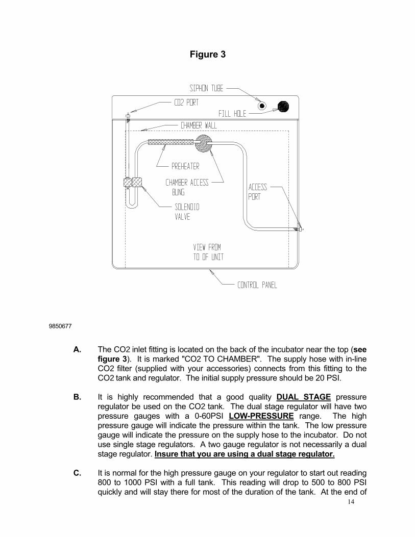
Figure 3
9850677
A. The CO2 inlet fitting is located on the back of the incubator near the top (see figure 3). It is marked "CO2 TO CHAMBER". The supply hose with in-line CO2 filter (supplied with your accessories) connects from this fitting to the CO2 tank and regulator. The initial supply pressure should be 20 PSI.
B. It is highly recommended that a good quality DUAL STAGE pressure regulator be used on the CO2 tank. The dual stage regulator will have two pressure gauges with a 0-60PSI LOW-PRESSURE range. The high pressure gauge will indicate the pressure within the tank. The low pressure gauge will indicate the pressure on the supply hose to the incubator. Do not use single stage regulators. A two gauge regulator is not necessarily a dual stage regulator. Insure that you are using a dual stage regulator.
C. It is normal for the high pressure gauge on your regulator to start out reading
800 to 1000 PSI with a full tank. This reading will drop to 500 to 800 PSI quickly and will stay there for most of the duration of the tank. At the end of
15
use, the pressure will drop quickly to zero, indicating that the tank is completely empty. Pure CO2 is in a liquid state in the new tank and a constant vapor pressure is generated in the tank above the liquid level, and the CO2 is drawn from the top as a gas. This same vapor pressure is maintained as long as any liquid is left in the tank. When the last of the liquid has evaporated into gas then the pressure will drop rapidly as the gas is drawn off.
D. Only medical grade CO2 should be used in your incubator. The use of a
lesser grade may damage your incubator and void your warranty. E. The microprocessor CO2 control system interprets the information from the
CO2 sensor, displays the CO2 concentration directly on the digital display, reads the CO2 set point, and controls the percentage of CO2 in the incubator chamber.
F. There are two types of CO2 sensors available, Thermal Conductivity (TC)
and Infrared (IR). The 2310 and 2300 units operate with TC sensors, and the 2400 units operate with IR sensors.
G. TC sensors operate under the principle that CO2 is 1.5 times denser than air
and if you measure the changes in density they can be interpreted as changes in CO2 content. This method of measurement is accurate, reliable and stable as long as all factors that influence air density are maintained unchanged. Factors that effect density are humidity and temperature. When the door of the incubator is opened, the humidity is reduced, the temperature is lowered and the thermal conductivity control system loses stability until the conditions in the incubator have recovered to original conditions.
H. IR sensors operate under the principle that a certain frequency of infrared
light is absorbed by CO2. The more CO2 is present the more light is absorbed. Advantages to this system are that it is only sensitive to CO2, so its accuracy is consistent no matter what the conditions are in the incubator.
I. Both types of CO2 sensors are factory calibrated and under normal
circumstances need no calibration in the fields; however, it is recommended that the accuracy of your CO2 control system be monitored by measuring the actual CO2 concentration on a weekly basis with a FYRITE or other measuring device. This should be done when the chamber has not been disturbed for an extended period of time, i.e. after the weekend or first thing on Monday morning.
5.10 Setting the CO2 Control: Attach the supply hose to the incubator and turn on the
CO2 supply. Set the CO2 control to the desired set point using the procedure described in section 5.3.
5.11 Adjusting CO2 Display: After the incubator has had several hours to stabilize at
16
CO2 set point, measure the actual CO2% with a Fyrite. If there is any difference between the Fyrite and the display, use the procedure described in section 5.4 for making the display match the Fyrite. See Section 6.0 for Fyrite use.
NOTE: When using the Fyrite, insure that gas is not being injected while the reading is being taken. Change the CO2 set point to 0.0 prior to taking the sample and then change the set point back to the desired value after the use of the Fyrite. 5.12 Alarm Conditions: The temperature control and the CO2 control are both equipped
with visual and audible alarms. A. Temperature Alarms: The temperature control has alarm indicators for high
and low conditions that are activated whenever the actual temperature is 1C° above or below the set point.
B. CO2 Alarms: The CO2 controller has alarm indicators for high and low alarm
conditions that are activated whenever the actual CO2% is 1% above or below the set point.
C. Audible Alarms: Both controls are equipped with audible alarms that are
activated when either of the HIGH or LOW indicators are activated. The audible alarms can be muted for a single alarm occurrence by pressing and holding down either the UP or DOWN button for several seconds until the MUTE light comes on. There is a built in delay of 15 minutes on the occurrence of a LOW alarm. This prevents the audible alarm from activating every time the door is opened and the temperature and CO2 drops.
5.13 Description of nGS (NO Gas Warning) Function: (If equipped) The CO2 Low alarm activates 15 minutes after the CO2 level drops below 4%, if the cause is not corrected in 5 minutes the CO2 display will flash nGS, indicating a no gas warning. nGS will continue to flash until the CO2 level has risen above 4%. The auditable alarm can be muted but the visual low alarm indicator will continue to be lit and the display will continue to flash nGS until cleared. No action is required by the user other than to correct the cause of the CO2 to drop. Note: It may take several hours after loss of gas before the CO2 low alarm comes on. This depends on the unit’s rate of decay. Low CO2 alarm does not activate until the CO2 is below 4%. Restore gas supply. Check CO2 tank and gas supply lines to the unit. As soon as the gas supply is restored and the CO2 level rises above 4.0%, the display will stop blinking nGS and will again show the sensor reading. No action is required by the user other than correcting the cause of the drop in gas supply. The auditable alarm can be muted but the visual low alarm indicator will continue to be lit and the display will continue to flash nGS until cleared.

17

18
FYRITE CO2 CHECKING
A Bacharach FYRITE CO2 Gas Analyzer is recommended to measure CO2 concentrations in the incubator chamber. This test instrument is not supplied with the incubator but is readily available from your dealer. Follow the instructions provided with the Fyrite instrument carefully to insure correct and accurate readings. 1. Press button on top of Fyrite canister to release CO2 concentration. Tip canister
to the side to ensure all fluid is released from the top of canister. 2. Loosen screw on slide scale and align top of fluid with zero on the scale. Tighten
screw. 3. Connect hose and aspirator bulb to unit being tested. The sample port for
connection is located in the upper front corner of the right side of the incubator. 4. Place the hose sampling cap directly over the plunger valve on top of canister
and depress firmly. 5. With button depressed, squeeze bulb 27 times. On the last squeeze and with
bulb still deflated, release hose from button. 6. Turn Fyrite canister upside down 3 times, each time allowing all fluid to flow to
the opposite end of the canister. 7. Tip canister to the 45 degree position to ensure all fluid has been released from
top of canister. 8. Read CO2 concentration in %. NOTE: Your Fyrite indicator will come with a complete set of detailed instructions which should be followed carefully. The fluid used inside this Fyrite instrument is poisonous and corrosive and must not be taken internally. In event of a spill or accidental body contact with the Fyrite fluid, follow instructions on the refill bottle carefully.
Section
6

19
MAINTENANCE NOTE: Prior to any maintenance or service on this unit, disconnect the service cord from the power supply. 7.1 Cleaning: Cleaning and decontamination are recommended on a regular basis.
To prepare the incubator for cleaning remove all parts such as the shelves, shelf standards and false ceiling. All stainless steel parts are autoclavable. Please review the cleaning procedures described in the Installation section for detailed instructions.
7.2 Check CO2 supply periodically and do not let it run out. (Automatic tank switches
are available from your dealer.) 7.3 CO2 supply lines and connections can be checked for leaks with a liquid soap
solution. Apply a liquid soap solution to all areas of the CO2 supply line and then look for bubbles which will indicate a leak.
7.4 Keep the CO2 flow system free of impurities. Erratic CO2 control is usually
traceable to the CO2 pressure regulator on the tank, impurities in the tank, or impurities in the solenoid valve. Replace the CO2 in-line filter every six (6) months or when the filter has become noticeably dirty on the upstream side. There is a CO2 filter attached to the tubing kit, and one inside the shadow box connected to the GAS-IN line.
7.5 Storage: If the incubator is to be turned off for any length of time, dry the chamber
and humidity pan thoroughly and leave at room temperature. Failure to do this may cause the interior to become contaminated. No adjustment to controls should be required when restarting the unit. If you intend to shut down the unit for transport, dry the chamber completely, remove the humidity pan and shelving, disconnect the CO2 supply and power cord, drain the water jacket and screw in the leveling feet. See Section 3.3 Lifting / Handling, for transport procedures.
7.6 There is no maintenance necessary for controls. If controls fail to operate as
specified, review Section 8.0 Troubleshooting, before calling for service.
Section
7
20
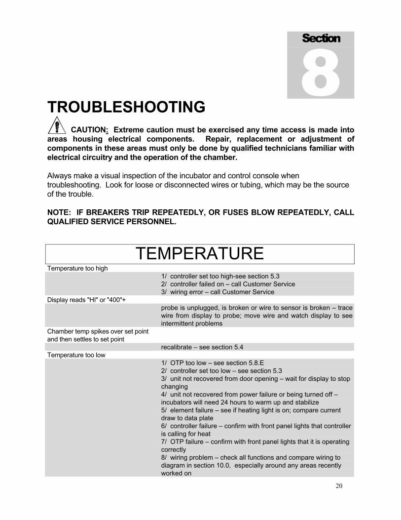
TROUBLESHOOTING CAUTION: Extreme caution must be exercised any time access is made into areas housing electrical components. Repair, replacement or adjustment of components in these areas must only be done by qualified technicians familiar with electrical circuitry and the operation of the chamber. Always make a visual inspection of the incubator and control console when troubleshooting. Look for loose or disconnected wires or tubing, which may be the source of the trouble. NOTE: IF BREAKERS TRIP REPEATEDLY, OR FUSES BLOW REPEATEDLY, CALL QUALIFIED SERVICE PERSONNEL.
TEMPERATURE Temperature too high 1/ controller set too high-see section 5.3
2/ controller failed on – call Customer Service 3/ wiring error – call Customer Service
Display reads "HI" or "400"+ probe is unplugged, is broken or wire to sensor is broken – trace
wire from display to probe; move wire and watch display to see intermittent problems
Chamber temp spikes over set point and then settles to set point
recalibrate – see section 5.4 Temperature too low 1/ OTP too low – see section 5.8.E
2/ controller set too low – see section 5.3 3/ unit not recovered from door opening – wait for display to stop changing 4/ unit not recovered from power failure or being turned off – incubators will need 24 hours to warm up and stabilize 5/ element failure – see if heating light is on; compare current draw to data plate 6/ controller failure – confirm with front panel lights that controller is calling for heat 7/ OTP failure – confirm with front panel lights that it is operating correctly 8/ wiring problem – check all functions and compare wiring to diagram in section 10.0, especially around any areas recently worked on
Section
8
21
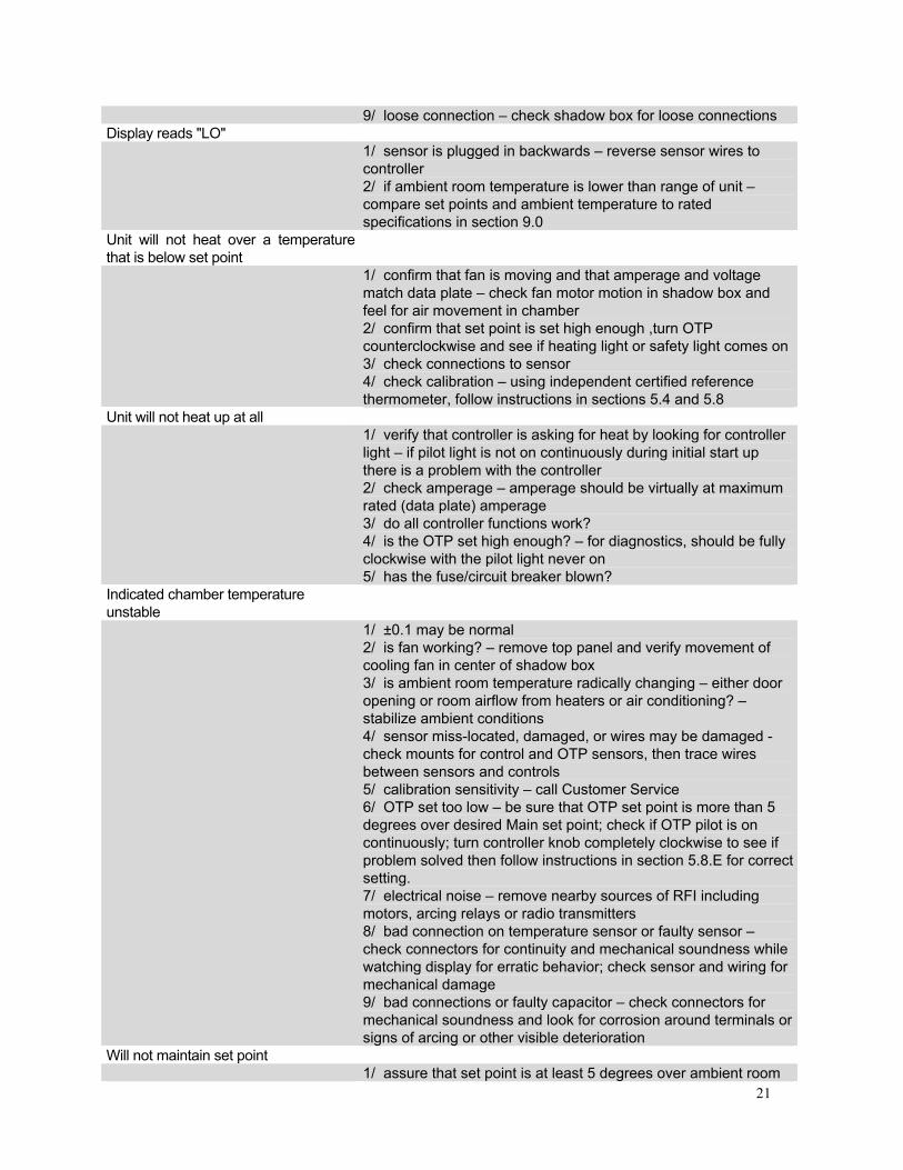
9/ loose connection – check shadow box for loose connections Display reads "LO" 1/ sensor is plugged in backwards – reverse sensor wires to
controller 2/ if ambient room temperature is lower than range of unit – compare set points and ambient temperature to rated specifications in section 9.0
Unit will not heat over a temperature that is below set point
1/ confirm that fan is moving and that amperage and voltage match data plate – check fan motor motion in shadow box and feel for air movement in chamber 2/ confirm that set point is set high enough ,turn OTP counterclockwise and see if heating light or safety light comes on 3/ check connections to sensor 4/ check calibration – using independent certified reference thermometer, follow instructions in sections 5.4 and 5.8
Unit will not heat up at all 1/ verify that controller is asking for heat by looking for controller
light – if pilot light is not on continuously during initial start up there is a problem with the controller 2/ check amperage – amperage should be virtually at maximum rated (data plate) amperage 3/ do all controller functions work? 4/ is the OTP set high enough? – for diagnostics, should be fully clockwise with the pilot light never on 5/ has the fuse/circuit breaker blown?
Indicated chamber temperature unstable
1/ ±0.1 may be normal 2/ is fan working? – remove top panel and verify movement of cooling fan in center of shadow box 3/ is ambient room temperature radically changing – either door opening or room airflow from heaters or air conditioning? – stabilize ambient conditions 4/ sensor miss-located, damaged, or wires may be damaged - check mounts for control and OTP sensors, then trace wires between sensors and controls 5/ calibration sensitivity – call Customer Service 6/ OTP set too low – be sure that OTP set point is more than 5 degrees over desired Main set point; check if OTP pilot is on continuously; turn controller knob completely clockwise to see if problem solved then follow instructions in section 5.8.E for correct setting. 7/ electrical noise – remove nearby sources of RFI including motors, arcing relays or radio transmitters 8/ bad connection on temperature sensor or faulty sensor – check connectors for continuity and mechanical soundness while watching display for erratic behavior; check sensor and wiring for mechanical damage 9/ bad connections or faulty capacitor – check connectors for mechanical soundness and look for corrosion around terminals or signs of arcing or other visible deterioration
Will not maintain set point 1/ assure that set point is at least 5 degrees over ambient room
22
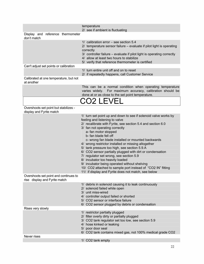
temperature 2/ see if ambient is fluctuating
Display and reference thermometer don’t match
1/ calibration error – see section 5.4 2/ temperature sensor failure – evaluate if pilot light is operating correctly 3/ controller failure – evaluate if pilot light is operating correctly 4/ allow at least two hours to stabilize 5/ verify that reference thermometer is certified
Can't adjust set points or calibration 1/ turn entire unit off and on to reset
2/ if repeatedly happens, call Customer Service Calibrated at one temperature, but not at another
This can be a normal condition when operating temperature varies widely. For maximum accuracy, calibration should be done at or as close to the set point temperature.
CO2 LEVEL Overshoots set point but stabilizes - display and Fyrite match
1/ turn set point up and down to see if solenoid valve works by feeling and listening to valve 2/ recalibrate with Fyrite, see section 5.4 and section 6.0 3/ fan not operating correctly a- fan motor stopped b- fan blade fell off c- wrong fan blade installed or mounted backwards 4/ wrong restrictor installed or missing altogether 5/ tank pressure too high, see section 5.9.A 6/ CO2 sensor partially plugged with dirt or condensation 7/ regulator set wrong, see section 5.9 8/ incubator too heavily loaded 9/ incubator being operated without shelving 10/ CO2 attached to sample port instead of “CO2 IN” fitting 11/ if display and Fyrite does not match, see below
Overshoots set point and continues to rise display and Fyrite match
1/ debris in solenoid causing it to leak continuously 2/ solenoid failed while open 3/ unit miss-wired 4/ controller output failed or shorted 5/ CO2 sensor or interface failure 6/ CO2 sensor plugged by debris or condensation
Rises very slowly 1/ restrictor partially plugged
2/ filter overly dirty or partially plugged 3/ CO2 tank regulator set too low, see section 5.9 4/ hose kinked or leaking 5/ poor door seal 6/ CO2 tank contains mixed gas, not 100% medical grade CO2
Never rises 1/ CO2 tank empty
23
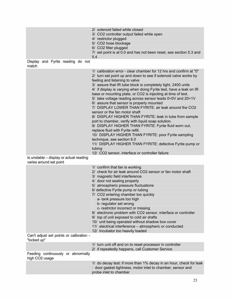
2/ solenoid failed while closed 3/ CO2 controller output failed while open 4/ restrictor plugged 5/ CO2 hose blockage 6/ CO2 filter plugged 7/ set point is at 0.0 and has not been reset, see section 5.3 and 5.4
Display and Fyrite reading do not match
1/ calibration error - clear chamber for 12 hrs and confirm at "0" 2/ turn set point up and down to see if solenoid valve works by feeling and listening to valve 3/ assure that IR tube block is completely tight, 2400 units 4/ if display is varying when doing Fyrite test, have a leak on IR base or mounting plate, or CO2 is injecting at time of test. 5/ take voltage reading across sensor leads 0=0V and 20=1V 6/ assure that sensor is properly mounted 7/ DISPLAY LOWER THAN FYRITE: air leak around the CO2 sensor or the fan motor shaft 8/ DISPLAY HIGHER THAN FYRITE: leak in tube from sample port to chamber, verify with liquid soap solution. 9/ DISPLAY HIGHER THAN FYRITE: Fyrite fluid worn out, replace fluid with Fyrite refill. 10/ DISPLAY HIGHER THAN FYRITE: poor Fyrite sampling technique, see section 6.0 11/ DISPLAY HIGHER THAN FYRITE: defective Fyrite pump or tubing 12/ CO2 sensor, interface or controller failure
Is unstable – display or actual reading varies around set point
1/ confirm that fan is working 2/ check for air leak around CO2 sensor or fan motor shaft 3/ magnetic field interference 4/ door not sealing properly 5/ atmospheric pressure fluctuations 6/ defective Fyrite pump or tubing 7/ CO2 entering chamber too quickly a- tank pressure too high b- regulator set wrong c- restrictor incorrect or missing 8/ electronic problem with CO2 sensor, interface or controller 9/ top of unit exposed to cold air drafts 10/ unit being operated without shadow box cover 11/ electrical interference – atmospheric or conducted 12/ Incubator too heavily loaded
Can't adjust set points or calibration - "locked up"
1/ turn unit off and on to reset processor in controller 2/ if repeatedly happens, call Customer Service
Feeding continuously or abnormally high CO2 usage
1/ do decay test: if more than 1% decay in an hour, check for leak : door gasket tightness, motor inlet to chamber, sensor and probe inlet to chamber
24
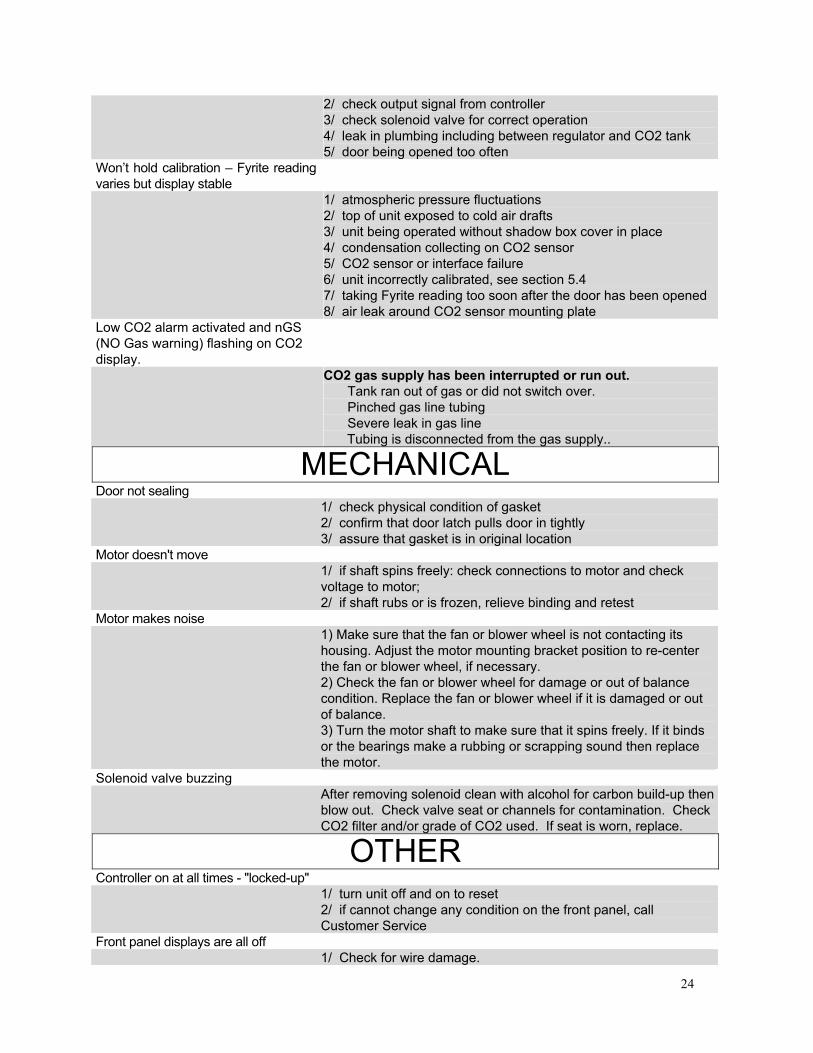
2/ check output signal from controller 3/ check solenoid valve for correct operation 4/ leak in plumbing including between regulator and CO2 tank 5/ door being opened too often
Won’t hold calibration – Fyrite reading varies but display stable
1/ atmospheric pressure fluctuations 2/ top of unit exposed to cold air drafts 3/ unit being operated without shadow box cover in place 4/ condensation collecting on CO2 sensor 5/ CO2 sensor or interface failure 6/ unit incorrectly calibrated, see section 5.4 7/ taking Fyrite reading too soon after the door has been opened 8/ air leak around CO2 sensor mounting plate
Low CO2 alarm activated and nGS (NO Gas warning) flashing on CO2 display.
CO2 gas supply has been interrupted or run out. Tank ran out of gas or did not switch over. Pinched gas line tubing Severe leak in gas line Tubing is disconnected from the gas supply..
MECHANICAL Door not sealing 1/ check physical condition of gasket
2/ confirm that door latch pulls door in tightly 3/ assure that gasket is in original location
Motor doesn't move 1/ if shaft spins freely: check connections to motor and check
voltage to motor; 2/ if shaft rubs or is frozen, relieve binding and retest
Motor makes noise 1) Make sure that the fan or blower wheel is not contacting its
housing. Adjust the motor mounting bracket position to re-center the fan or blower wheel, if necessary. 2) Check the fan or blower wheel for damage or out of balance condition. Replace the fan or blower wheel if it is damaged or out of balance. 3) Turn the motor shaft to make sure that it spins freely. If it binds or the bearings make a rubbing or scrapping sound then replace the motor.
Solenoid valve buzzing After removing solenoid clean with alcohol for carbon build-up then
blow out. Check valve seat or channels for contamination. Check CO2 filter and/or grade of CO2 used. If seat is worn, replace.
OTHER Controller on at all times - "locked-up" 1/ turn unit off and on to reset
2/ if cannot change any condition on the front panel, call Customer Service
Front panel displays are all off 1/ Check for wire damage.
25
Unit or wall fuse/circuit breaker is blown
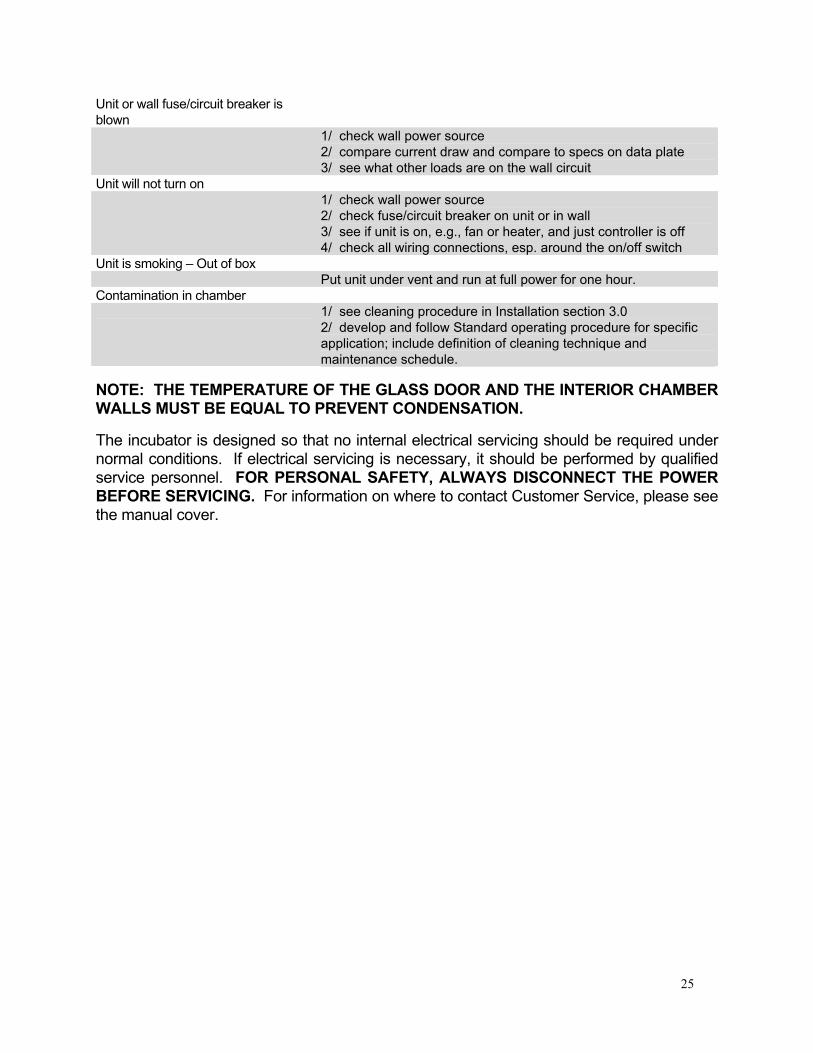
1/ check wall power source 2/ compare current draw and compare to specs on data plate 3/ see what other loads are on the wall circuit
Unit will not turn on 1/ check wall power source
2/ check fuse/circuit breaker on unit or in wall 3/ see if unit is on, e.g., fan or heater, and just controller is off 4/ check all wiring connections, esp. around the on/off switch
Unit is smoking – Out of box Put unit under vent and run at full power for one hour. Contamination in chamber 1/ see cleaning procedure in Installation section 3.0
2/ develop and follow Standard operating procedure for specific application; include definition of cleaning technique and maintenance schedule.
NOTE: THE TEMPERATURE OF THE GLASS DOOR AND THE INTERIOR CHAMBER WALLS MUST BE EQUAL TO PREVENT CONDENSATION. The incubator is designed so that no internal electrical servicing should be required under normal conditions. If electrical servicing is necessary, it should be performed by qualified service personnel. FOR PERSONAL SAFETY, ALWAYS DISCONNECT THE POWER BEFORE SERVICING. For information on where to contact Customer Service, please see the manual cover.

26
PARTS LIST
Description 115V 220V Anode 0260500 0260500 CO2 Display 1750559 1750560 CO2 Control w/Alarm – 2310 only 1750551 1750552 CO2 Filter 100199 100199 Control 4 Loop Pad 1750725 1750725 Cord Set 1800510 104192 Door Switch X1000022 X1000022 Door Heater 103068 103068 Element Coil 2350503 120071 Fan Blade 2600526 2600526 Fan Motor 4880508 4880507 Fuse 3300516 3300515 Gasket 2310 3450645 3450645 Gasket 3450644 3450644 Glass Door Latch 9530516 9530516 IR Transmitter, 2400 units 8320510 8320510 Over Temperature Safety 100001 100001 Pilot Light, Green 200021 200021 Pilot Light, Red 200020 200020 Power Inlet Fuse 3300516 3300515 Power Switch 103351 103351 Solenoid Valve 9740508 9740509 TC CO2 Sensor w/Interface, 2310,2300 units 9700501 9700501 Transformer, 2400 units 6750507 N/A * Must specify 220V-Jumpers on PCA must be reset from 115V to 220V.
Section
9

27
UNIT SPECIFICATIONS These units are 115 volt or 220 volt. Please refer to the unit data plate for its individual specification.
Weight Shipping Net 2300 280 lbs. 221 lbs. 2310 280 lbs. 257 lbs. 2350 600 lbs. 442 lbs. 2400 280 lbs. 221 lbs. 2450 800 lbs. 442 lbs.
Dimensions Exterior WxDxH (IN.)
Interior WxDxH (IN.)
2300 26.5x26x40 20.5x20x28 2310 26.5x25.25x39.75 20.5x20x25.75 2350 26.5x26x80 20.5x20x28 2400 26.5x26x40 19X20X25.5 2450 26.5x26x80 19X20X25.5 (x2)
Capacity Cubic Feet 2310 2 2300 6.7 2350 6.7 (x2) 2400 6.7 2450 6.7 (x2)
Temperature Range Uniformity CO2
2300 Amb. 8°C to 60°C +0.1°C @ 37°C 0 – 20% 2310 Amb. 8°C to 60°C +0.1°C @ 37°C 0 – 20% 2350 Amb. 8°C to 60°C +0.1°C @ 37°C 0 – 20% 2400 Amb. 8°C to 60°C +0.1°C @ 37°C 0 – 20% 2450 Amb. 8°C to 60°C +0.1°C @ 37°C 0 – 20%
Model Amp Voltage Hertz
2300 5 amp 120V 60 Hz
28
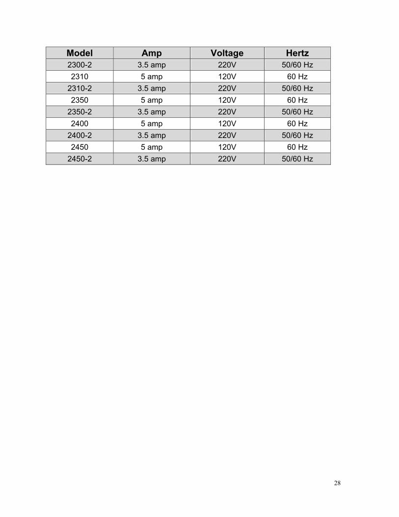
Model Amp Voltage Hertz 2300-2 3.5 amp 220V 50/60 Hz 2310 5 amp 120V 60 Hz
2310-2 3.5 amp 220V 50/60 Hz 2350 5 amp 120V 60 Hz
2350-2 3.5 amp 220V 50/60 Hz 2400 5 amp 120V 60 Hz
2400-2 3.5 amp 220V 50/60 Hz 2450 5 amp 120V 60 Hz
2450-2 3.5 amp 220V 50/60 Hz
29
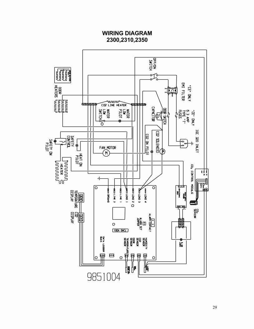
WIRING DIAGRAM 2300,2310,2350
30
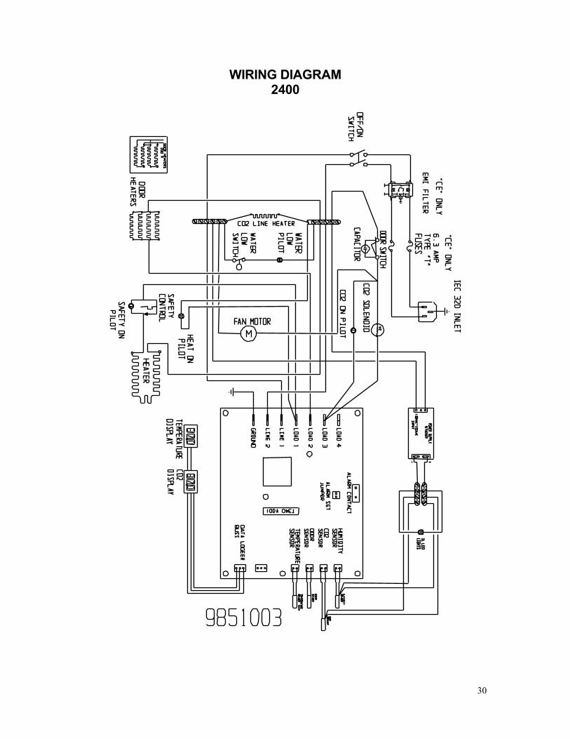
WIRING DIAGRAM 2400

31
SHELDON MANUFACTURING, INC. LIMITED WARRANTY
Sheldon Manufacturing, Inc., (“Manufacturer”) warrants for the original user of this product in the U.S.A. only that this product (parts only if outside of the U.S.A.) will be free from defects in material and workmanship for a period of two years from the date of delivery of this product to the original user (the “Warranty Period”). During the Warranty Period, Manufacturer, at its election and expense, will repair or replace the product or parts that are proven to Manufacturer’s satisfaction to be defective, or, at Manufacturer’s option, refund the price or credit (against the price of future purchases of the product) the price of any products that are proven to Manufacturer’s satisfaction to be defective. This warranty does not include any labor charges if outside of the U.S.A. This warranty does not cover any damage due to accident, misuse, negligence, or abnormal use. Use of Manufacturer’s product in a system that includes components not manufactured by Manufacturer is not covered by this warranty. This warranty is void in the event that repairs are made by anyone other than Manufacturer without prior authorization from Manufacturer. Any alteration or removal of the serial number on Manufacturer’s products will void this warranty. Under no circumstances will Manufacturer be liable for indirect, incidental, consequential, or special damages. The terms of this warranty are governed by the laws of the state of Oregon without regards to the principles of conflicts of laws thereof. If any provision of this limited warranty is held to be unenforceable by any court of competent jurisdiction, the remainder of this limited warranty will remain in full force and effect. This warranty is in lieu of and excludes all other warranties or obligations, either express or implied. Manufacturer expressly disclaims all implied warranties, including without limitation, the warranties of merchantability and fitness for a particular purpose.
For fast and efficient support, please have the following information available anytime you request service: Model __________ Serial No. __________ Part No. __________

32
Order From VWR
Call 800-932-5000 from anywhere in the U.S. and Canada
Sales & Inventory Locations: Pacific Northwest Area Anchorage, AK Salt Lake City, UT San Francisco, CA Seattle, WA Tualatin, OR
Midwest Area Chicago, IL Detroit, MI Indianapolis, IN Minneapolis, MN St. Louis, MO
Northeast Area Boston, MA Cincinnati, OH Cleveland, OH Pittsburgh, PA Rochester, NY
Southeast Area Atlanta, GA Oak Ridge, TN
Southwest Area Albuquerque, NM Denver, CO Phoenix, AZ San Diego, CA San Dimas, CA
Gulf Area Austin, TX Dallas, TX Houston, TX Lake Charles, LA
Mid-Atlantic Area Baltimore, MD Branford, CT Bridgeport, NJ S. Plainfield, NJ
VWR Canlab Offices Mississauga, Ontario Ville Mont-Royal, Québec Edmonton, Alberta
Or Call Direct for Specialized Service Locations: VWR International 3000 Hadley Rd S. Plainfield, NJ 07080 (908) 757-4045 fax: (908) 757-0313 Puerto Rico Carr. #869 Km. 1.5 M4 Royal Industrial Park Catano, PR 00962 (787) 788-3222 fax: (787) 78804320
Switzerland Ruchligstrasse # 20 P.O. Box 464 Dietikon, Switzerland CH-8953 011-41-1-745-1155 fax: 011-41-1-745-1150 VWR Direct 911 Commerce Ct. Buffalo Grove, IL 60089 (800) 444-0880
VWR Furniture Division P.O. Box 3405 Irving, TX 75015 (972) 714-0336 VWR National Accounts 1310 Goshen Pkwy W. Chester, PA 19380 (610) 431-1700
Visit Our Web Site at http://www.vwrsp.com