volume - ii technical specifications multi purpose cyclone shelters · · 2016-01-20technical...
TRANSCRIPT
VOLUME - II
TECHNICAL SPECIFICATIONS
MULTI PURPOSE CYCLONE SHELTERS
1 The work shall be executed as per the description of item given in the „Bill Of
Quantities‟, Specifications, Drawings, General Conditions of Contract, Additional Conditions of Contract, CPWD Specifications, New Delhi, for civil works (updated with correction slips issued upto last date of submission of tender) and latest CPWD specification, New Delhi, for electrical works (updated with correction slips issued upto last date of submission of tender), instructions & orders to the contractor from time to time during tendency of work.
2 For items not covered under latest CPWD specification, for (civil works) /
latest CPWD specification for Electrical works and in particular specification or nomenclature of the individual item as above, the work shall be done as per latest relevant BIS codes of practice.
3 In case of non availability of any specification in the above paras or any
overlapping provisions, non-clarity on any issue, applicability of particular provision out of above, shall be decided by Engineer-in-charge whose decision shall be final & binding on the contractor.
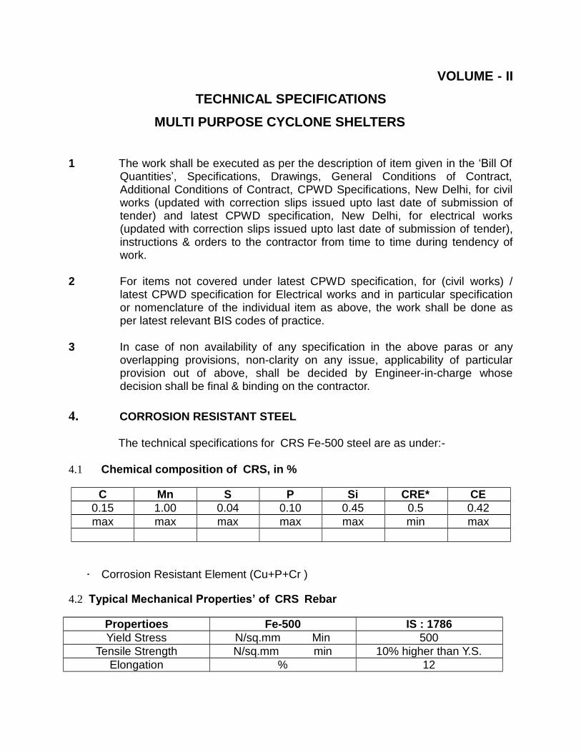
4. CORROSION RESISTANT STEEL
The technical specifications for CRS Fe-500 steel are as under:-
4.1 Chemical composition of CRS, in %
C Mn S P Si CRE* CE
0.15 1.00 0.04 0.10 0.45 0.5 0.42
max max max max max min max
· Corrosion Resistant Element (Cu+P+Cr )
4.2 Typical Mechanical Properties’ of CRS Rebar
Propertioes Fe-500 IS : 1786
Yield Stress N/sq.mm Min 500
Tensile Strength N/sq.mm min 10% higher than Y.S.
Elongation % 12

5 Resistance Properties
Operation Size IS : 1786 Fe- 500
BEND Upto 22mm 4d Over 22mm 5d
Rebend Upto 10mm 5d Over 10mm 7d
5.1 Alternate Immersion Test
Conducted with apparatus that simulates the splash and tidal zone of the
coast and areas of heavy rainfall as per ASTM G-44-94. Specimens are dipped alternately in 3.5% NaCL solution for 10 mts. and exposed to air for 50 mts. This 1-h cycle is continued for 720 hrs. Corrosion resistance is measured by the weight loss shown by specimens.
5.2 Salt Spray Test
Effects of marine environment are simulated in salt spray test as per ASTM B – 117. Mild steel CTD rebars and CRS samples are suspended from the ceiling and subjected to a fine salt solution (5% NacL) spray for exactly the same length of time. After the stipulated time period (720 hrs), both samples are cleaned and their rate of corrosion calculated according to a specific formula based on the specimen‟s weight loss. CRS is not susceptible to pitting corrosion.
5.3 Atmospheric Exposure Test
Extensive field exposure tests were conducted for two years for CRS and
mild steel CTD bars as per ASTM< G-50 in industrial as well as in a saline seaside environment. The results show that CRS bars are at least 1.8 times more corrosion resistant than ordinary (CTD) rebars.
5.4 Sulphur Dioxide Test
To simulate the condition of a highly polluted industrial atmosphere, this test is conducted as per ASTM G87-90 for a test duration of 720 hrs.
5.5 Potentio – Dynamic Test
The test is conducted as per ASTM G -5-94 in 0.04 N NaOH + 10,000ppm of chloride solution to have a very close simulation prevailing in concrete under actual condition. After stabilisation of Open Circuit Potential (OCP), 100 mV above and below OCP in Tafel region allows the determination of I corr.
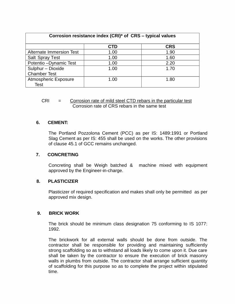
Corrosion resistance index (CRI)* of CRS – typical values
CTD CRS
Alternate Immersion Test 1.00 1.90
Salt Spray Test 1.00 1.60
Potentio –Dynamic Test 1.00 2.20
Sulphur – Dioxide 1.00 1.70 Chamber Test
Atmospheric Exposure 1.00 1.80 Test
CRI = Corrosion rate of mild steel CTD rebars in the particular test Corrosion rate of CRS rebars in the same test
6. CEMENT:
The Portland Pozzolona Cement (PCC) as per IS: 1489:1991 or Portland Slag Cement as per IS: 455 shall be used on the works. The other provisions of clause 45.1 of GCC remains unchanged.
7. CONCRETING
Concreting shall be Weigh batched & machine mixed with equipment approved by the Engineer-in-charge.
8. PLASTICIZER
Plasticizer of required specification and makes shall only be permitted as per approved mix design.
9. BRICK WORK
The brick should be minimum class designation 75 conforming to IS 1077: 1992.
The brickwork for all external walls should be done from outside. The contractor shall be responsible for providing and maintaining sufficiently strong scaffolding so as to withstand all loads likely to come upon it. Due care shall be taken by the contractor to ensure the execution of brick masonry walls in plumbs from outside. The contractor shall arrange sufficient quantity of scaffolding for this purpose so as to complete the project within stipulated time.

10. WATER PROOFING ON TERRACE
The water proofing for the terraces, underground tanks / toilet floor etc. shall be got executed only through the authorized applicators of the manufacturers and the guarantee for the same shall be in the name of EPI / Owner for a period of ten years after the expiry of defect liability period on the prescribed format given in the GCC.
11 GENERAL
11.1 The Materials/Products used on the works shall be one of the preferred
Make/Brands/Manufacturers given in the tender documents approved by EPI/NDMA
11.2 Flooring shall be of stone as per drawing / design & specification. The pattern
shown in the drawing, if any can be modified as per site requirement by Engineer-in-charge and nothing extra shall be payable over and above the rate quoted.
11.3 Due care shall be given to HFL of the area while fixing plinth level of
structures.
11.4 Plumbing & sanitary work to be executed by licensed / expert plumber and
the plumbing scheme / drawing to be got approved from Engineer-in-charge.
11.5 The contractor shall be responsible for all protection of sanitary, water supply,
electrical fittings & fixture against pilferage, breakage during period of installation until the completion of work and handed over to Authorities.
11.6 The electrical works shall be executed only through licensed electrician and the agency shall have to submit the valid license of electricians before starting the work.
11.7 It will be the sole responsibility of contractor to obtain all statutory approvals / compliance required, if any, for construction / implementation of the project including Forest clearance and completion clearance from the all relevant statutory bodies for plumbing, sewerage, sanitary and PHE work, fire, department for fire protection, fire fighting, electrical works, pollution control authorities etc. and for all other services as included in the scope of contract etc. from the concerned department as required within the stipulated time frame, only statutory charges shall be borne by the NDMA.

11.8 The contractor shall have to execute the work in pace and in such a way to facilitate other agency, if any, engaged simultaneously for execution of other works required for completion.
11.9 Unless otherwise specified in the schedule of quantities, the rates tendered
by the contractor shall be all inclusive and shall apply to all heights, leads, depths & nothing extra shall be payable on this account.
11.10 On completion of work, the tenderer shall submit four prints of “As built”
drawings to Engineer-in-charge at no extra payment.
12.0 DIESEL GENERATOR SET
Work covered by this contract shall include manufacture, supply,
transportation, delivery, installation, testing and commissioning of direct start sound proof diesel generator sets suitable for round the clock operation at up to rated output with permissible overload along with associated works.
The DG set shall be complete with steel base frame, Anti vibration Mounting pads engine mounted radiator, battery & battery charger, day service tank, piping with accessories for water & HSD, exhaust piping, residential silencer, etc, The Generator shall be complete with standard control panel.
Any equipment not specifically mentioned herein but essential for completeness of the DG set shall also be supplied
The diesel generator shall have the minimum following features as under.
The generator sets should be able to accept rated load in one step at rated pf, a test certificate to this effect on prototype model needs to be furnished.
The minimum rating of the Generator shall be AS PER RATED KVA under standard conditions of BS 5514.
The Generator Set should comply with ISO 8528-5, Class G3 requirements
for transient performance.
The vendor shall provide for one source responsibility for the Generating Set
and accessories for spares service & warranty.
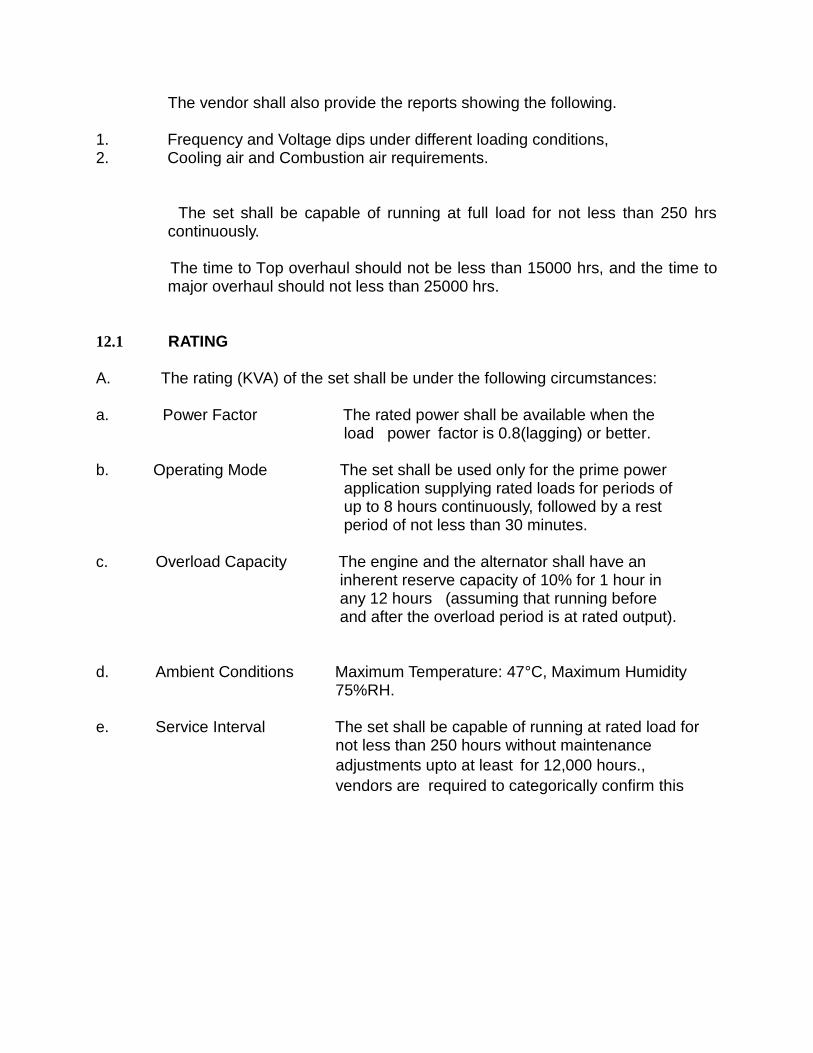
The vendor shall also provide the reports showing the following.
1. Frequency and Voltage dips under different loading conditions, 2. Cooling air and Combustion air requirements.
The set shall be capable of running at full load for not less than 250 hrs continuously.
The time to Top overhaul should not be less than 15000 hrs, and the time to major overhaul should not less than 25000 hrs.
12.1 RATING
A. The rating (KVA) of the set shall be under the following circumstances:
a. Power Factor The rated power shall be available when the
load power factor is 0.8(lagging) or better.
b. Operating Mode The set shall be used only for the prime power
application supplying rated loads for periods of up to 8 hours continuously, followed by a rest period of not less than 30 minutes.
c. Overload Capacity The engine and the alternator shall have an
inherent reserve capacity of 10% for 1 hour in any 12 hours (assuming that running before and after the overload period is at rated output).
d. Ambient Conditions Maximum Temperature: 47°C, Maximum Humidity
75%RH.
e. Service Interval The set shall be capable of running at rated load for
not less than 250 hours without maintenance
adjustments upto at least for 12,000 hours.,
vendors are required to categorically confirm this

f. Shaft Speed The rotational speed shall not exceed 1,500 Rev
Motor Starting Vendors to confirm The largest motor the Dg set can start With TVD restricted to 20%,
h. Loads The Generator Set shall be capable of operating in
conjunction with non-linear and harmonic generating electric loads including the UPS system. Vendor to confirm the maximum non-inear loads that can be applied on the machine
B. The DG Set shall be able to start in manual mode even in cold conditions, without any adverse effects on its performance, and shall take full rated load within 10 seconds (wake up time) from the starting signal. For switching in cold conditions, Jacket water heating facility should be provided. Before starting, pre-lubrication arrangement for the engine shall be provided if required.
C. D.G. Set should be designed for low specific fuel consumption. Vendors to
confirm the KWH/ lit at 100% rating and part loads
12.2 HOUSING
A purpose-constructed building shall be provided (by others) for the generator set and its auxiliary plants.
12.3 DIESEL ENGINE
1. The engine shall be a four stroke, multi-cylinder, dynamically balanced, direct
injection, turbocharged and inter cooled, heavy duty, industrial machine constructed to BS 5514. It shall be fitted with renewable wet cylinder liners and shall be directly coupled to the dynamically balanced alternator with both units mounted on a common grid steel bedplate.
2. The diesel engine shall have a minimum BHP as required as per rating
of the set.
3. The diesel engine shall be provided with electronic governing isochronous
type with frequency regulation under steady state condition within limits of
± 0.25%.
4. Governor shall be electronic,
5. The critical speeds of the crankshaft shall be min. 20% of the rated speed.
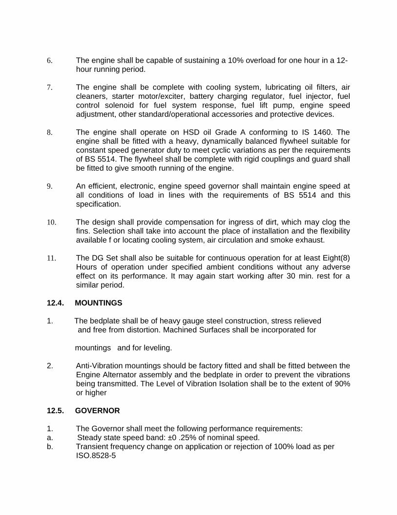
6. The engine shall be capable of sustaining a 10% overload for one hour in a 12-
hour running period.
7. The engine shall be complete with cooling system, lubricating oil filters, air
cleaners, starter motor/exciter, battery charging regulator, fuel injector, fuel control solenoid for fuel system response, fuel lift pump, engine speed adjustment, other standard/operational accessories and protective devices.
8. The engine shall operate on HSD oil Grade A conforming to IS 1460. The
engine shall be fitted with a heavy, dynamically balanced flywheel suitable for constant speed generator duty to meet cyclic variations as per the requirements of BS 5514. The flywheel shall be complete with rigid couplings and guard shall be fitted to give smooth running of the engine.
9. An efficient, electronic, engine speed governor shall maintain engine speed at
all conditions of load in lines with the requirements of BS 5514 and this specification.
10. The design shall provide compensation for ingress of dirt, which may clog the
fins. Selection shall take into account the place of installation and the flexibility available f or locating cooling system, air circulation and smoke exhaust.
11. The DG Set shall also be suitable for continuous operation for at least Eight(8)
Hours of operation under specified ambient conditions without any adverse effect on its performance. It may again start working after 30 min. rest for a similar period.
12.4. MOUNTINGS
1. The bedplate shall be of heavy gauge steel construction, stress relieved
and free from distortion. Machined Surfaces shall be incorporated for
mountings and for leveling.
2. Anti-Vibration mountings should be factory fitted and shall be fitted between the
Engine Alternator assembly and the bedplate in order to prevent the vibrations being transmitted. The Level of Vibration Isolation shall be to the extent of 90% or higher
12.5. GOVERNOR
1. The Governor shall meet the following performance requirements: a. Steady state speed band: ±0 .25% of nominal speed. b. Transient frequency change on application or rejection of 100% load as per
ISO.8528-5

c. Recovery time to steady state speed band on application of 100 % Load as per ISO 8528-5
3. The electrical over speed trip provided shall operate at 110% of the rated
speed and shall be only be reset by hand.
12.6 . ENGINE COOLING
1. The engine shall be cooled by means of a RADIATOR as per design.
2. The Diesel engine shall be protected against Low Coolant Level
3. A thermostatically operated by-pass valve shall be fitted in the cooling
system to maintain an optimum operating temperature during starting and running conditions. Drain cocks shall be provided so that all the water can be drained from the system.
4. Separate oil cooler shall be used for cooling the engine oil. A thermostatic
by-pass valve shall be incorporated.
12.7 . LUBRICATION SYSTEM
1. Pre-lubrication system for lubrication of engine before starting shall be provided
complete with necessary pumps, piping and drilled oil passage strainer, oil cooler, relief valve, etc. Engine lubrication shall be by a closed circuit wet sump, forced feed system supplied by an engine driven pump fitted with pressure regulating and relief valves, sump suction filter and changeover renewable full- flow line filters.
2. The sump shall be fitted with an easily accessible drain point.
12.8. STARTING SYSTEM AND BATTERY CHARGING
1. The starting system shall comprise a 24 V heavy duty high lead acid battery, as
required, and electric starting motor. The battery shall be sized to give not less than six consecutive starts of the engine at 0°C. The starting system shall be complete with necessary relays, solenoid valves for fuel, control and indicating panels as specified and required. The Engine Shall be provided with an over cranking relay to avoid any over cranking of the engine.
2. An engine driven alternator and charging system shall be provided, with
sufficient capacity to maintain the battery in a condition to fulfill the starting requirements. An automatic changeover shall be provided such that battery

charging is carried out by the engine driven alternator at all times when the generator set is running.
3. The mains powered charger shall be suitable for operation on a 240 V single
phase supply and shall be complete with the following indications and features:
Battery Charge / Discharge Current, Boost Charge / Trickle Charge Selector, On/Off Switch, Fault Indication.
4. The Battery Charger shall have a selector switch by which the rate of charging
the batteries can be selected.
5. If the equipment does not start within three starting cycles with appropriate
interval between each attempt, the starting circuit shall be locked out and audio-visual alarm shall be given.
12.9 ALTERNATOR
The alternator shall be 4 pole, 3 phase, salient pole, self / separate (with PMG) excitation, resolving field, brush less type, self-regulating, continuously rated, and manufactured in accordance with BS2613 / BS 5000 and suitable for feeding 415 V, 3 Phase 4 Wire, 50 Hz AC system with neutral point brought out. The alternator shall be screen protected, fan ventilated and confirming to an IP Classification of IP 21/23. The alternator shall be rated for 1500 RPM with KVA rating to produce rated output under site conditions It shall include Digital Voltage Regulator, Voltage adjusting potentiometer and low speed protection.
1. The alternator shall be capable of withstanding a 10% overload for 1 hour in
any 12-hour period under the specified conditions of temperature, humidity and atmospheric pressure. The alternator shall be capable of maintaining a short- circuit current of three times the full load current for a period of 10 seconds.
2. The alternator rotor assembly shall comprise exciter rotor, full wave silicon
bridge rectifier, surge protection device and salient pole rotating field system. The rotor shall be fitted with interconnected pole face damping windings. A filtration circuit shall be provided to minimize the effect of switching surges generated from electronic loads and eliminate any requirement for an increased rating of the set due to the UPS or such other non-linear loads. The non-linear load handling capacity of the alternator should be minimum 40% of its rated capacity. Suitable type of excitation system shall be provided for this.
3. An automatic Voltage Regulator shall maintain the voltage to within ±0..25% of
the rated Voltage for a power factor between 0.8 and unity,.

4. The alternator shall be capable of continuous operation with a phase current
imbalance of 33% of rated current whist maintaining the output voltage within ±0.25% of the rated Value.
5. The alternator shall have pre-packed grease lubricated ball or roller
bearings and provided with facilities for re-greasing whilst in service. The alternator shall be foot mounted on a common bed frame with the prime mover and shall be close-coupled to the engine flywheel housing.
6. Alternator windings shall be Class H insulation for Class H temperature rise (BS
2757) and impregnated with thermosetting varnish suitable for use in tropical climates. Ample Ventilation shall be provided by shaft mounted centrifugal fan. The alternator shall be provided with an anti-condensation heater, which shall be automatically disconnected when the generator set is starting or running..
7. The main exciter shall receive power from a permanent magnet generator
through separator auxiliary windings on stator via Digital Voltage Regulator. The Digital Voltage Regulator shall be of solid-state circuitry and shall provide regulated voltage to the exciter compensating for all normal variations. The main exciter output is fed to the main windings via a rotating 3-ph bridge rectifier assembly, which shall be protected from voltage surges, short circuit, overload and diode failures. The DVR and control gear shall be mounted in a component box on the side of the machine.
8. Voltage Regulation shall be within ± 0.25% under all conditions of load,
power factor and temperature including cold to hot variation. There shall be no radio or television interference. Line Voltage wave form shall be as true as possible with a total harmonic distortion not exceeding 3% on application of 3- Phase loads.
9. The excitation system and engine governor should be such that the
alternator is capable of starting up induction motors having a starting KVA of not less than 2 times the alternator rated KVA. Manufacturer should indicate the voltage dip and duration under such conditions as required under equipment data.
12.10 INSTRUMENTATION
1. Instrumentation shall be provided and mounted on the Generator Set
to monitor the following:
a. Engine Speed, b. Oil Pressure, c. Oil Temperature,

d. Water Temperature.
2. A Gauge Board shall be provided with all the indicators grouped together.
3. The generator shall be provided with a microprocessor-based controller with a
facility for remote start, remote annunciation and remote communication capability through the telephone /GSM network.It should be possible to monitor the parameters of the engine and the alternator and display the status of the faults on the Dg set if any and generate a complete report on the PC individually or on a network
The following minimum monitoring & protection is required
Engine monitoring.
a. Coolant temperature. b. Coolant level. c. .Fuel level. d. Battery voltage. e. RPM. f. Fault oil pressure g. Engine start count down.
Alternator Monitoring
a Current. (I1, I2, I3). b Frequency c Voltage (L-L & L-N) d KVA. e KVAR f Power Factor g Percentage alternator duty heavily ie actual load / KW rating.
The engine is required to shut down under the following condition of faults High coolant temperature, Low coolant level, Low oil Pressure, Overspeed Over Crank ( The Dg set shall not take any further attempts to start after it fails to start upon three attempts in the manual mode).
The Generator shall be protected against the following electrical faults
Overload and short circuit,Ground fault,Over current,Over frequency, Under frequency,Under Voltage,Over Voltage,Locked Rotor ( Failed to Crank) It Should be possible to read the data ie Parameters and Shutdown status Locally on the Dg Set. All the above Parameters should be displayed on The Local Control Panel through appropriate meters and status on faults should be indicated through a facia annunciator.

It should be possible to display all the functions as above on a personal
computer.
12.11 RADIO INTERFERENCE
All equipments, provided under the scope, shall be so designed that they shall not cause interference with radio equipment. In the event of the inherent characteristics of the equipment being such that radio interference is possible, efficient devices to nullify the same shall be provided.
12.12 CONTROL PANEL
The panel shall be totally enclosed, made of Mild Steel sheet of at least 14 SWG thickness, freestanding, floor mounted and totally enclosed type. The cubicle shall be painted with one coat of red oxide primes and two coats of spray finish super enamel paint. Wiring circuit diagram of the panel should be affixed inside the cubicle so that when front hinged panel door is removed / opened it is clearly visible. All the switchgears, control devices, push buttons, indication lamps should be clearly labeled to indicate their nomenclature and operation. The wiring condition in the control panel shall be ferruled.
The Control panel shall have the following instrumentation
1 No. A.C. square voltmeter suitably scaled (144 sq.mm.) 1 No. Voltmeter selector switch 1 No A.C. Square C.T. operated ammeter suitably scaled to measure current in phases or lines(144 sq.mm.) 1 No. Ammeter selector Switch 3 Nos. Current Transformers of suitable ratio. 1 No. Frequency Meter (144 sq.mm.)
1 No. Power Factor Meter 1 No. 3-Phase 4-Wire suitable energy meter 1 No. running time meter (non-resettable type) 1 No. 4 Pole Air Circuit Breaker (EDO) of suitable rating complete with overload trip, short circuit trip, relays,

12.13 EXHAUST SYSTEM
1. The engine exhaust piping shall be amply sized for minimum back
pressure and connected to the engine manifold through flexible connection or an expansion joint on one side and to a silencer on the other side along with pipe. The silencer shall be of package type with adequate attenuation for urban use, constructed from heavy gauge mild steel. The sound absorbent infill shall be non-hygroscopic, vermin proof, non-combustible material. Engine shall be provided with residential type silencers so as to reduce the sound level by 15 dBA at a distance of 1 meter from the DG set as per the norms.
2. The exhaust piping from the silencer onward shall be laid up to the
specified / approved level and discharged through a rain cowl. Entire exhaust piping and silencer shall be insulated with 50 mm thick, 64 kg / cum density, fiberglass, white wool. The insulation shall be held in position with 0.63 mm dia, 20 mesh, galvanized steel wire mesh and finished neatly with 26 SWG Aluminium Cladding.
3. Flanged Connections to the silencer and between pipe sections shall be
made. Minimum wall thickness of pipes and the silencer shall be 3 mm. A stainless steel bellows unit shall be provided for connection onto the engine.
4. Exhaust pipes within the building shall be lagged and guarded to prevent
accidental contact up to a height of 2.5 m. No part of any exhaust system installed outside the building shall be less than 3 m from the ground level. Passage of exhaust pipes through walls or the roof shall be sleeved and shall be shrouded to prevent ingress of rain or vermin. Exhaust emission control shall be as per Pollution Control Board regulations and all other statutory authorities.
5. Exhaust piping shall be fabricated from Class „B‟ MS pipes conforming to IS
1239 of size suitable to limit backpressure to within permissible limit. The insulation thickness stipulated in the schedule of quantities shall be checked by the tenders to achieve a maximum temperature of 70°C on the outside surface of the insulated pipe and supporting calculation for the backpressure shall be furnished. Flanged joints in the exhaust piping shall be covered with removable insulation at suitable intervals for permitting access to the joint, as and when required. All flanged joints shall have spiraget high temperature gasket. The piping shall be installed with necessary thermal expansion facility

as required. Exhaust piping shall be connected to the engine by means of flexible section or an expansion joint and shall also be graded to a drain pocket inside the building. The pocket shall be fitted with a drain cock.
12.14 FUEL TANKS
1. A Fuel Day Tank of not less than 990 Litres Storage Capacity complete with
mechanical fuel oil level indicator to indicate „high‟ and „low‟ levels and isolation valves, shall be supplied for pumping and storing fuel oil from barrels to Day Tank as necessary. The Tank shall be complete with a floor stand such that the tank is installed at the optimum height which allows correct suction pressure to the Fuel lift pump of the Generator set when the fuel oil in the tank is at any level between low level and high level.
2. The tank shall be constructed from Mild Steel of not less than 14 SWG Thickness in accordance with relevant IS standards. It shall be complete with filter breather unit and drain plug. The associated fittings shall be constructed from materials which are suitable for long term contact with diesel fuel and shall not include yellow brass, low grade of copper and zinc, lead, and galvanized metals. The fuel piping and tanks shall be designed to free from leakage and airlocks. The fuel tank shall be supplied with a level gauge to indicate the oil level in the tank in litres. The following fitting shall be included:
a) lowest point in tank complete with isolating valve,
b) Outlet pipe complete with manually operated isolation valve and mechanically
operated isolation valve (for fire shut-down),
c) Fuel Inlet pipe from the filling point at the top of the tank,
d) Fuel return inlet pipe connection (from the generator set).
12.15. FUEL PIPE WORK AND VALVES
1. The Generator package shall include the supply, installation, connection,
testing and commissioning of all pipes and valves for the fuel system including, but not limited to the following
a) Day tank filling pipe
b) Generator fuel supply and return pipes.
c) Bulk oil storage and transfer system piping and accessories.
2. All pipes, valves, fittings and connection materials shall be designed for use in conjunction with diesel fuel oil. All fuel piping shall be suitably corrosion protected.
12.16. FUEL FILTERS
A supply line fuel filter shall be fitted and shall be of the cartridge type.
12.17. TESTING AND COMMISSIONING
1. The Generating Sets shall be tested at the manufacturer‟s premises for the
guaranteed performance and fuel consumption at various loads for 8 hours, overload capacity and satisfactory operation of the protection systems. All faults, control functions and site load conditions shall be simulated, checked and proved. All the above testing shall be carried out in the presence of or his authorized representative. In addition, tests to prove the transient performance as specified above, on block loading, shall be conducted.
2. After installation at site the set shall be run for a minimum period of 2 hours
gradually loaded to 50% load. On satisfactory completion of the load run the test shall be run for a period of 8 hours at 100% full load. All consumables including fuel, lube oil and load banks required for commissioning the set shall be supplied and arranged by the purchaser.
3. The trial shall be conducted in the presence of the authorized representative
and the test results shall be recorded in an approved format. Any abnormal condition occurring during the trial run of the DG Set shall also be recorded. Test Results shall be recorded at 30 minutes intervals.
4. Tests proving the satisfactory performance of all operating gear, safety
functions and control shall be carried out.
5. Performance test at site shall include (but not limited to) the following test
acceptance criteria:
a) Fuel Consumption at 60%, guaranteed performance. 80%, 100% and 110%
load Alternator efficiencies as determined by the tests at the manufacturer‟s works shall be used as the basis of calculation of
b) Voltage variation± 0.25%
12.18. INSTRUCTIONS MANUALS AND CATALOGUES

a). Two copies of operator‟s guide, manuals, maintenance schedules, repair / overhaul instructions for the complete equipments shall be supplied by the supplier.
12.19 OVERLOAD CAPACITY
The DG Set shall be able to withstand 10% overloading for one hour in twelve hours.
12.20. GUARANTEE
The Supplier shall guarantee for satisfactory performance of the DG Set, panel, etc. for a period of 12 calendar months from the date of successful commissioning and handling over of the equipment for the operation against all manufacturing defects.
12.21 STATUARY REGULATIONS AND APPROVALS
The Supplier shall be responsible to maintain all STATUARY NORMS prescribed by CPCB (or by any other competent authority) either for noise level or emission level or any other parameter, from time to time. Declaration in this regard shall be submitted by the supplier along with his technical bid. Also all approvals by the CPCB or any other competent authority regarding any parameter directly attributable to the DG sets shall be the sole responsibility of the supplier.
12.22 DG DRAWINGS
The Supplier shall be responsible to provide all P&I diagrams for water system, fuel system & also chimney sizes as per back pressure requirements. Typical P&I diagrams for water and fuel systems are given for reference. Any other drawing required for completion of the system is to be furnished for approval by the supplier.
13. APPROVED LIST OF MATERIALS/MAKES
SL.No NAME OF ITEMS LIST OF APPROVED MANUFACTURERS / BRAND / APPLICATORS
CIVIL
1 Cement ACC/ GRASIM/ ULTRATECH/ LAFARGE/
2 Reinforcement Bars TATA(TISCON), SAIL, RINL.

3 White Cement JK , BIRLA WHITE
4 Ceramic Floor Tiles Premium quality NITCO, JOHNSON, VERMORA, Bell
5 Ceramic Tiles for Dado Premium NITCO, JOHNSON, VERMORA, KAJARIA
6 Vitrified/ Rectified Tiles Premium Quality NITCO, JOHNSON, VERMORA, ORIENT
7 Glass Mosaic Tiles Italia, Lamosaic, Littleglass
8 Float Glass Modi, Saint Gobin, Indo-Asahi,
9 Concrete Interlocking Pavement Wondercrete, Eurocon, AP Tiles and Concrete Paver Block Stylish Interlocking Pvt. Ltd.
10 Flush Door/ Kit ply, Greenply, Century door, Truwood door, Dura door, Sarda
12 Cylindrical locks/ locks Godrej/ Foam Industries equiovalent.
13 Extruded Aluminium sections INDAL, JINDAL,HINDALCO
14 Aluminium Composite Panel Alstrong, Aluco-bond, Aludecor, Durabuild
16 Reflective Glass for glazing AIS, Saint Gobian, Pilkington
17 Minarel board false ceiling Armstrong/ AMF / OWA
18 UPVC rain water pipes with fittings Oriplast, Supreme, Finolex
19 Polycarbonate Sheet GE Plastic or Equivalent
20 Exterior type acrylic based paint Excel Total of Nerolac, Apex ultima of Asian Paint or equivalent of ICI
21 Wall Putty Birla, JK
22 Distemper Asian Paint, Berger, ICI, Nerolac
23 Plastic emulsion Paint Premium emulsion of Asian Paints, Delux acrylic emulsion of ICI, Rangoli fashion of Berger, Allscape of Nerolac
24 Synthetic Paint Asian Paint, Berger, ICI,
Nerolac
25 Zinc Chromate Primers Shalimar, Asian Paint, Berger, ICI
27 Chemical / Mechanical Anchor HILTI, FISCHER Fastners
28 Hydraulic door closer Hardwyn make (Eddy) or equivalent
29 Floor spring for aluminium door Hardwyn, Garnish
30 Fittings for Aluminium doors and Ebco, Doorline windows.
31 Water Proofing Compound/ Choksey, Sika Qualcrete, Admixtures Degussa, Fosroc,
32 Epoxy Grout for tile fixing Laticrete, Bal endula or
equivalent.
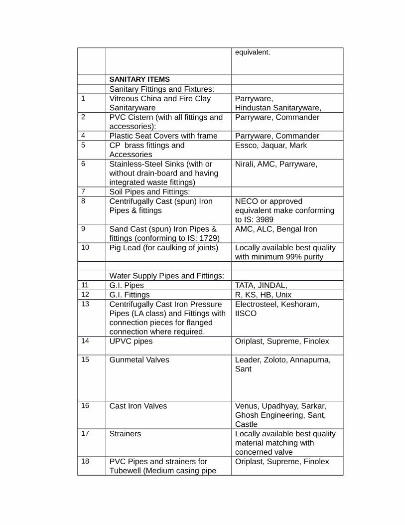
SANITARY ITEMS
Sanitary Fittings and Fixtures:
Vitreous China and Fire Clay Parryware, Sanitaryware Hindustan Sanitaryware,
PVC Cistern (with all fittings and Parryware, Commander accessories):
Plastic Seat Covers with frame Parryware, Commander
CP brass fittings and Essco, Jaquar, Mark Accessories
Stainless-Steel Sinks (with or Nirali, AMC, Parryware, without drain-board and having integrated waste fittings)
Soil Pipes and Fittings:
Centrifugally Cast (spun) Iron NECO or approved Pipes & fittings equivalent make conforming
to IS: 3989
Sand Cast (spun) Iron Pipes & AMC, ALC, Bengal Iron fittings (conforming to IS: 1729)
Pig Lead (for caulking of joints) Locally available best quality with minimum 99% purity
Water Supply Pipes and Fittings:
G.I. Pipes TATA, JINDAL,
G.I. Fittings R, KS, HB, Unix
Centrifugally Cast Iron Pressure Electrosteel, Keshoram, Pipes (LA class) and Fittings with IISCO connection pieces for flanged connection where required.
UPVC pipes Oriplast, Supreme, Finolex
Gunmetal Valves Leader, Zoloto, Annapurna,
Sant
Cast Iron Valves Venus, Upadhyay, Sarkar, Ghosh Engineering, Sant, Castle
Strainers Locally available best quality material matching with concerned valve
PVC Pipes and strainers for Oriplast, Supreme, Finolex Tubewell (Medium casing pipe
1
2
4
5
6
7
8
9
10
11
12
13
14
15
16
17
18

Locally available best quality material having minimum thickness of 8mm
BE/ Kirloskar Pumps
Crompton/Siemens Motors
KSB Pump & Motor
KALAMA Pumps & Motor
H. Guru, Danfoss, Fiebig
Finolex or equivalent
L&T, Siemens, GE
Hind Ceramic, Orind or equivalent. Parry, Cera, Hindustan
Commeander, Patel
Tata, Jindal, NEZONE
HB, Zoloto, K.S
Neelkantha, AMC, Corba
Modi, Atul, Silver, Gold Fish, Jolly
Essco, Jaquar, Mark
GPA, SANT, L & K
Leaders, Kent, Zoloto
Oriplast,Suprime, Finolex, Prince
RIF, BIG, NECO
Perfect, Burn, RK
Laxmi, Sood & Sood, Jain & Co.
IISCO, Kesoram, Electro Steel
Sintex, Patton or equivalent
SL.No NAME OF ITEMS LIST OF APPROVED
MANUFACTURERS / BRAND / APPLICATORS
ELECTRICALS
1 Contactor Siemens, ABB, L&T, GE, Schneider, BCH
2 TPN switch fuse unit / switch Siemens, L& T, GE, C&S,
and matching thickness strainers conforming to IS: 12818)
MS Top nipple Pipe for Tubewell
Lift Pump set
Submersible Pump set
Instruments & Electricals
Pressure Gauge & Pressure Switch
Water proof flat Cable
Electrical accessories to Motor Control Panel
Sewerage and drainage
Stoneware pipes and fittings
19
20
21
22
23
24
25
26 Vitreous China Sanitary Ware
27 Plastic W.C seats
28 GI Pipes
29 GI fittings
30 Stainless Steel Sink
31 Mirror
32 C.P Pillar cock, Bibcocks, stop-
cocks and other CP fittings
33 Brass Bib & Stop cock
34 Valves
Soil, Waste & Rainwater pipe and fittings
35 Unplasticised-PVC
36 Sand Cast
37 Stone ware Pipes & Gully
38 RCC Pipe
39 C.I. S/S Pipes
40 PVC Tank
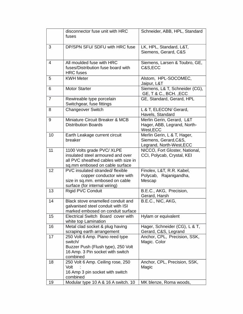
disconnector fuse unit with HRC Schneider, ABB, HPL, Standard fuses
3 DP/SPN SFU/ SDFU with HRC fuse LK, HPL, Standard, L&T,
Siemens, Gerard, C&S
4 All moulded fuse with HRC Siemens, Larsen & Toubro, GE,
fuses/Distribution fuse board with C&S,ECC HRC fuses
5 KWH Meter Alstom, HPL-SOCOMEC, Jaipur, L&T
6 Motor Starter Siemens, L& T, Schneider (CG), GE, T & C., BCH. ,ECC
7 Rewireable type porcelain GE, Standard, Gerard, HPL Switchgear, fuse fittings
8 Changeover Switch L & T, ELECON/ Gerard, Havels, Standard
9 Miniature Circuit Breaker & MCB Merlin Gerin, Gerard, L&T Distribution Boards Hager, ABB, Legrand, North-
West,ECC
10 Earth Leakage current circuit Merlin Gerin, L & T, Hager, breaker Siemens, Gerard,C&S,
Legrand, North-West,ECC
11 1100 Volts grade PVC/ XLPE NICCO, Fort Gloster, National, insulated steel armoured and over CCI, Polycab, Crystal, KEI all PVC sheathed cables with size in sq.mm embosed on cable surface
12 PVC insulated stranded/ flexible Finolex, L&T, R.R. Kabel, copper conductor wire with Polycab, Rajanigandha,
size in sq.mm. embosed on cable Mescap surface (for internal wiring)
13 Rigid PVC Conduit B.E.C., AKG, Precision, Gerard, Harsh
14 Black stove enamelled conduit and B.E.C., NIC, AKG, galvanised steel conduit with ISI marked embosed on conduit surface
15 Electrical Switch Board cover with Hylam or equivalent white top Lamination
16 Metal clad socket & plug having Hager, Schneider (CG), L & T, scraping earth arrangement Gerard, C&S, Legrand
17 250 Volt 6 Amp. Piano reed type Anchor, CPL, Precision, SSK, switch/ Magic. Color Buzzer Push (Flush type), 250 Volt 16 Amp. 3 Pin socket with switch combined
18 250 Volt 6 Amp. Ceiling rose, 250 Anchor, CPL, Precision, SSK, Volt : Magic 16 Amp 3 pin socket with switch combined
19 Modular type 10 A & 16 A switch. 10 MK blenze, Roma woods,
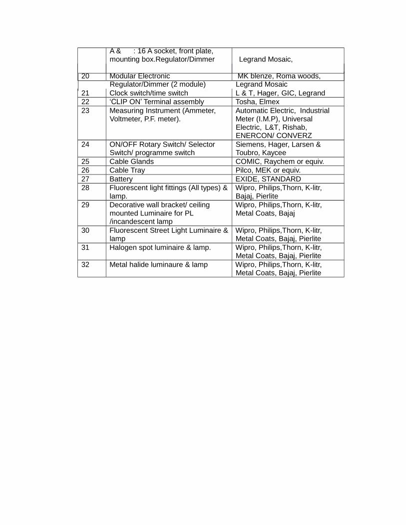
A & : 16 A socket, front plate, mounting box.Regulator/Dimmer Legrand Mosaic,
20 Modular Electronic MK blenze, Roma woods, Regulator/Dimmer (2 module) Legrand Mosaic
21 Clock switch/time switch L & T, Hager, GIC, Legrand
22 „CLIP ON‟ Terminal assembly Tosha, Elmex
23 Measuring Instrument (Ammeter, Automatic Electric, Industrial Voltmeter, P.F. meter). Meter (I.M.P), Universal
Electric, L&T, Rishab, ENERCON/ CONVERZ
24 ON/OFF Rotary Switch/ Selector Siemens, Hager, Larsen & Switch/ programme switch Toubro, Kaycee
25 Cable Glands COMIC, Raychem or equiv.
26 Cable Tray Pilco, MEK or equiv.
27 Battery EXIDE, STANDARD
28 Fluorescent light fittings (All types) & Wipro, Philips,Thorn, K-litr, lamp. Bajaj, Pierlite
29 Decorative wall bracket/ ceiling Wipro, Philips,Thorn, K-litr, mounted Luminaire for PL Metal Coats, Bajaj /incandescent lamp
30 Fluorescent Street Light Luminaire & Wipro, Philips,Thorn, K-litr, lamp Metal Coats, Bajaj, Pierlite
31 Halogen spot luminaire & lamp. Wipro, Philips,Thorn, K-litr, Metal Coats, Bajaj, Pierlite
32 Metal halide luminaure & lamp Wipro, Philips,Thorn, K-litr, Metal Coats, Bajaj, Pierlite

33 Lamp Holder (Pendent racket or Anchor, SSK, Magic Batten)
34 Exhaust Fan G.E.C., Crompton, Polar, EPC, Usha
35 Ceiling Fan Decorative fan of Crompton, Polar, Khaitan
36 Busbar Trunking/Rising Main Control & Switchgear (C & S), Zeta. ,ECC
37 Ammeter/Voltmeter selector switch Kaycee, L&T, Switron
38 Relay Alsthom, GE, L&T, Syntron, Control Group
39 Current Transformer Kappa, L&T, C&S, AE, SIEMENS,ECC
40 Capacitor L&T, Manual, EPCOS
41 Decorative Street Light Poles Metal Coats, KLITE
42 Sodium vapour, Murcury vapour Philips, Crompton, Wipro MHL fittings and lamps
43 Cable Jointing Kit Frontec, Raycham, M-seal, Denson
44 Passenger Elevator Otis / Kone/ Thyssenkrupp
45 Air-Conditioners Hitachi, Carrier, Voltas, Blue- star
46. Diesel Generator Set 15/25 KVA Kirloskar, Cummins,
Universal Power, Caterpilar,Jackson

Power, Caterpilar,Jackson