volume deficits of castings made from copper - bdguss€¦ · volume deficits of castings made from...
TRANSCRIPT
BDG Reference Sheet VDG Specification
P 211 Version: September 2010
Only applies to English translation: The English translation is believed to be accurate. In case of discrepancies, the German version is alone authoritative and controlling.
To be obtained from: BDG-Informationszentrum Giesserei, Sohnstraße 70, D-40237 Düsseldorf, Tel.: +49-211-68 71 252, Fax: -361, www.bdguss.de
Page 1 of 26
© B
UN
DE
SVE
RB
AN
D D
ER
DE
UT
SCH
EN
GIE
SSE
RE
I-IN
DU
STR
IE (
BD
G)
Volume Deficits of Castings Made from Copper and Copper Alloys
CONTENTS
1. Scope ........................................................ 2 1.1 General information ................................... 2 1.2 Alloys ........................................................ 2 1.3 Casting process ......................................... 2
2. Explanatory notes ................................... 2 2.1 Volume deficits ......................................... 2 2.1.1 Shrinkage cavities (Micro porosity) ........... 2 2.1.2 Hot cracks ................................................. 4 2.1.3 Gas porosity .............................................. 4 2.2 Other flaws ................................................ 5
3. Potential effects of porosity .................. 6 3.1 Static strength........................................... 6 3.2 Strength under cyclic loading (dynamic strength) .. 6 3.3 General leak tightness and mating surfaces
.................................................................. 6 3.4 Surface ...................................................... 7 3.5 Heat Treatment ......................................... 7
4. Evaluating the porosity of castings ...... 7 4.1 Radiographic test with image intensifier
(RT) ........................................................... 8 4.2 Ultrasonic test (UT) ................................... 9 4.3 Leak tightness test (LT) ............................. 9 4.4 Visual test (VT) .......................................... 9 4.5 Density test ............................................... 9 4.6 Microsection test and section test .......... 10 4.7 Penetrant test ......................................... 10
5. Literature references, standards, guidelines .............................................. 11
Appendix 1 – Material Related Shape of Pores 12 Appendix 1.1 Copper and Copper-Chromium Alloys
............................................................... 12 Appendix 1.2 Copper-Zinc Alloys (CuZn/Brass) ... 13 Appendix 1.3 Copper-Tin Alloys (CuSn/Bronze) ... 15 Appendix 1.4 Copper-Tin-Zinc Alloys (CuSnZn/Red
Brass) ..................................................... 16 Appendix 1.5 Copper-Aluminium Alloys (CuAl/Al-
Bronze) ................................................... 17
Appendix 2 – Porosity evaluation by means of microsection testing, section testing and quantitative image analysis ......... 19
A 2.1 Reference Areas for the pore evaluation . 19 A 2.2 Porosity key ............................................ 22 A 2.2.1 Definition and application recommendation
for the reference area roughness [Rz] ....... 22 A 2.2.2 Examples of porosity keys ....................... 24
A 2.3 Drawing notes ....................................... 24 A 2.3.1 Collective note ........................................ 25 A 2.3.2 Notes for defined areas .......................... 25
Appendix 3 – Definition of other flaws ............ 26
Reference Sheet compiled by BDG Technical Committees Copper Casting
BDG Reference Sheet VDG Specification
P211 Version: September 2010
To be obtained from: BDG-Informationszentrum Giesserei, Sohnstraße 70, D-40237 Düsseldorf, Tel.: +49-211-68 71 252, Fax: -361, www.bdguss.de
Page 2 of 26
© B
UN
DE
SVE
RB
AN
D D
ER
DE
UT
SCH
EN
GIE
SSE
RE
I-IN
DU
STR
IE (
BD
G)
1 Scope
1.1 GENERAL INFORMATION This BDG reference sheet applies to castings made from copper and copper alloys. The objective of this Guideline is to describe requirements for the casting quality and their uniform entry into technical documents. The scope of this reference sheet is restricted to inner and outer volume deficits (porosity). Other flaws such as sink marks, cold flow marks, segregations, burrs, draw marks, and heat check patterns are not part of this Guideline. Porosity can be minimized, but not precluded, if the design engineer and caster collaborate.
1.2 ALLOYS The scope of this reference sheet is restricted to castings made of copper according to the relevant standard DIN EN 1982.
1.3 CASTING PROCESS The contents of this BDG reference sheet refer to sand and permanent mould casting and variants showing a similar solidification behaviour.
2 Explanatory notes
2.1 VOLUME DEFICITS
2.1.1 Shrinkage cavities (Micro porosity) Shrinkage cavities result from the thermophysical properties of the cast materials during solidification. It is impossible to manufacture castings that are completely free of shrinkage cavities. Shrinkage cavities might contain gases such as H2, H2O, CO, CO2 or segregations, e. g. lead.
BDG Reference Sheet VDG Specification
P211 Version: September 2010
To be obtained from: BDG-Informationszentrum Giesserei, Sohnstraße 70, D-40237 Düsseldorf, Tel.: +49-211-68 71 252, Fax: -361, www.bdguss.de
Page 3 of 26
© B
UN
DE
SVE
RB
AN
D D
ER
DE
UT
SCH
EN
GIE
SSE
RE
I-IN
DU
STR
IE (
BD
G)
Ts = melting point
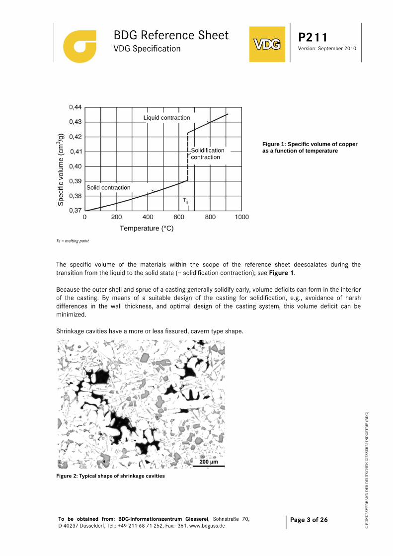
The specific volume of the materials within the scope of the reference sheet deescalates during the transition from the liquid to the solid state (= solidification contraction); see Figure 1. Because the outer shell and sprue of a casting generally solidify early, volume deficits can form in the interior of the casting. By means of a suitable design of the casting for solidification, e.g., avoidance of harsh differences in the wall thickness, and optimal design of the casting system, this volume deficit can be minimized. Shrinkage cavities have a more or less fissured, cavern type shape.
Figure 2: Typical shape of shrinkage cavities
Liquid contraction
Solidification contraction
Solid contraction
Spe
cific
vol
ume
(cm
3 /g)
Temperature (°C)
Figure 1: Specific volume of copper as a function of temperature
BDG Reference Sheet VDG Specification
P211 Version: September 2010
To be obtained from: BDG-Informationszentrum Giesserei, Sohnstraße 70, D-40237 Düsseldorf, Tel.: +49-211-68 71 252, Fax: -361, www.bdguss.de
Page 4 of 26
© B
UN
DE
SVE
RB
AN
D D
ER
DE
UT
SCH
EN
GIE
SSE
RE
I-IN
DU
STR
IE (
BD
G)
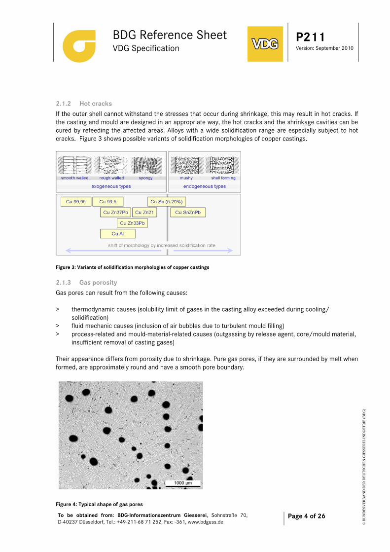
2.1.2 Hot cracks If the outer shell cannot withstand the stresses that occur during shrinkage, this may result in hot cracks. If the casting and mould are designed in an appropriate way, the hot cracks and the shrinkage cavities can be cured by refeeding the affected areas. Alloys with a wide solidification range are especially subject to hot cracks. Figure 3 shows possible variants of solidification morphologies of copper castings.
Figure 3: Variants of solidification morphologies of copper castings
2.1.3 Gas porosity Gas pores can result from the following causes: > thermodynamic causes (solubility limit of gases in the casting alloy exceeded during cooling/
solidification) > fluid mechanic causes (inclusion of air bubbles due to turbulent mould filling) > process-related and mould-material-related causes (outgassing by release agent, core/mould material,
insufficient removal of casting gases) Their appearance differs from porosity due to shrinkage. Pure gas pores, if they are surrounded by melt when formed, are approximately round and have a smooth pore boundary.
Figure 4: Typical shape of gas pores

BDG Reference Sheet VDG Specification
P211 Version: September 2010
To be obtained from: BDG-Informationszentrum Giesserei, Sohnstraße 70, D-40237 Düsseldorf, Tel.: +49-211-68 71 252, Fax: -361, www.bdguss.de
Page 5 of 26
© B
UN
DE
SVE
RB
AN
D D
ER
DE
UT
SCH
EN
GIE
SSE
RE
I-IN
DU
STR
IE (
BD
G)
2.1.3.1 Gas porosity caused by thermodynamics Copper and Copper alloys have a decreasing solubility for elementary gases as temperature decreases. During cooling of the melt and solidification (during the liquid-to-solid transition), the solubility limit can therefore be exceeded and gas can be released, leading to the formation of gas pores. These gas pores frequently accumulate in the area of remaining solidification.
Figure 5: Hydrogen solubility of copper In alloys with a distinct solidification range, gas precipitation preferably takes place between the dendrite arms. As a result, gas pores produced by the release of gas generally do not have round contours, but rather must arrange themselves in their shape with the dendrite network. The contour rounding depends on the gas content of the melt.
2.1.3.2 Gas porosity caused by fluid mechanics During mould filling, gases from the ambient air are included if the metal flow is turbulent. Gas pores caused by fluid mechanics generally are round as a result of transitional stresses between gas and melt.
2.1.3.3 Gas porosity caused by mould materials A thermally activated contact reaction between the metal melt and the mould material or the mould aids, such as release agents or die lubricants, can result in gases being released, which diffuse into the melt and are included during solidification. These gas pores are likewise generally round as a result of transitional stresses between gas and melt. They are frequently just beneath the casting surface. Note: In general, both shrinkage and gas porosity occur together. The gas pores are normally enlarged by the shrinkage and frequently lose their round shape as a result.
2.2 OTHER FLAWS In addition to porosity, other flaws may occur that can influence the casting quality, such as cold flow marks as well as oxide films, stick marks, draw marks, burrs, heat check patterns, sand, and slag inclusions. These flaws are defined in Appendix 3. However, they are not part of this reference sheet. As far as possible, reference is made to other guidelines and standards that deal with these flaws and their test methods.
BDG Reference Sheet VDG Specification
P211 Version: September 2010
To be obtained from: BDG-Informationszentrum Giesserei, Sohnstraße 70, D-40237 Düsseldorf, Tel.: +49-211-68 71 252, Fax: -361, www.bdguss.de
Page 6 of 26
© B
UN
DE
SVE
RB
AN
D D
ER
DE
UT
SCH
EN
GIE
SSE
RE
I-IN
DU
STR
IE (
BD
G)
3 Potential effects of porosity Depending on the type and properties of the component as well as the load case, pores in castings can affect the strength, leak tightness under pressure, surface characteristics, and/or appearance of the component. For technical components, the effect of porosity on the component strength must be considered in particular. The same porosity can have different effects on statically and dynamically stressed components. For static loading as well as for cyclic loading, points of force application, stress intensity, and areas with the greatest stress concentration must be known in order to ensure suitable selection of pore classes.
3.1 STATIC STRENGTH When a force is applied to a component, this causes stress in the cross section under load. This stress is proportional to the force divided by the cross-sectional area. If the cross section is reduced (weakened) because of pores the stress increases. As soon as the resulting stress exceeds the elastic limit of the material, permanent deformation occurs, which increases the strength of the material but on the other hand might also lead to fracture. In addition to this increase in stress caused by the reduction in the cross-section, a notch effect arises, depending on the pore geometry. For static loads, primarily the cross-sectional weakening and thus the pore content relative to the area must be considered critical. Under bending load and torsional load, the position of the porosity in relation to the neutral axis must be observed. Especially in the case of shrinkage pores, the porosity is located in the excess material area and therefore near the neutral axis. As a result, the strength reduction in the total cross-section is proportional to the areal porosity content with good approximation.
3.2 STRENGTH UNDER CYCLIC LOADING (DYNAMIC STRENGTH) The strength of a component under cyclic loading is determined to a large extent by notch factors in addition to the material. Geometric contours as well as inhomogeneities caused by oxide films, inclusions, microstructural components, intermetallic phases and casting flaws can lead to notches having greater notch factors than those of pores. Pores have different notch effects depending on their shape, their position relative to the casting surface, and their arrangement relative to each other. The notch effect > Increases with the areal porosity content > Decreases with increasing roundness, greater radius, and increasing distance of the pores from the
casting surface
3.3 GENERAL LEAK TIGHTNESS AND MATING SURFACES When gas pores, shrinkage cavities, and hot cracks are directly connected with the casting skin (open pores, sink marks) or when they are cut during machining, this may lead to leakage of the components or mating surfaces depending on pore distribution. In connection with the requirement for leak tightness under pressure, hot cracks and interconnected shrinkage cavities in particular must be considered critical. Depending on their shape and size, pores can cause damage and/or impairment of seals.
BDG Reference Sheet VDG Specification
P211 Version: September 2010
To be obtained from: BDG-Informationszentrum Giesserei, Sohnstraße 70, D-40237 Düsseldorf, Tel.: +49-211-68 71 252, Fax: -361, www.bdguss.de
Page 7 of 26
© B
UN
DE
SVE
RB
AN
D D
ER
DE
UT
SCH
EN
GIE
SSE
RE
I-IN
DU
STR
IE (
BD
G)
3.4 SURFACE Porosity on or just below the surface may lead to stress peaks in a component which is under cyclic load causing a crack initiation. The possibilities of surface coatings are affected by remaining residues/ impurities in the open cavities which can lead to flaws in subsequent coating processes.
3.5 HEAT TREATMENT Like many other materials copper and its alloys can be annealed (taking into account the mandatory requirements of temperature and time) to specifically adjust or optimize the mechanical properties. Possible processes are soft annealing, homogenization, stress relieving and hardening. In general heat treatment does not have any effect on porosity with the exception of die cast components in which gases were enclosed under pressure during solidification. In particular on or just below the surface gases can cause blisters during heat treatment. In die casting, blistering can be minimized by applying forced venting or vacuum to the die.
4 Evaluating the porosity of castings The degree of porosity depends on the material, the manufacturing process, and the process-compatible design of the component itself, its function and the degree of permissible porosity. Differentiation is made between macroporosity and microporosity: Macroporosity includes all pores whose size and shape can be determined with the emmetropic human eye or an auxiliary means with the same resolution (such as X-ray method). These are pores with a minimum extent of about 0.5 mm. Microporosity includes all pores whose size and shape cannot be reliably evaluated with the emmetropic human eye. They range up to an extent of 0.5 mm diameter. The minimum detectable pore size depends on the resolution of the auxiliary means used. Porosity requirements must be based on the component loads (static strength, fatigue limit, leak tightness under pressure and function of machined surfaces, appearance of unfinished casting surfaces). The evaluation criteria and scales for this must be defined between the manufacturer and the purchaser before the contract is awarded. It may be useful to define porosity criteria for a component that apply only to specifically defined reference areas; see Appendix 2 “Porosity evaluation by means of microsection testing, section testing and quantitative image analysis”
BDG Reference Sheet VDG Specification
P211 Version: September 2010
To be obtained from: BDG-Informationszentrum Giesserei, Sohnstraße 70, D-40237 Düsseldorf, Tel.: +49-211-68 71 252, Fax: -361, www.bdguss.de
Page 8 of 26
© B
UN
DE
SVE
RB
AN
D D
ER
DE
UT
SCH
EN
GIE
SSE
RE
I-IN
DU
STR
IE (
BD
G)
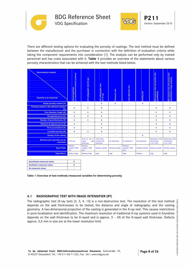
There are different testing options for evaluating the porosity of castings. The test method must be defined between the manufacturer and the purchaser in connection with the definition of evaluation criteria while taking the component requirements into consideration [1]. The analysis can be performed only by trained personnel and has costs associated with it. Table 1 provides an overview of the statements about various porosity characteristics that can be achieved with the test methods listed below.
Determination method Quantity to be measured V
isua
l ins
pect
ion
(on
mac
hine
d fu
ncti
onal
sur
face
s)
2-D
rad
iogr
aphi
c te
st (X
-ray
)
3-D
rad
iogr
aphi
c te
st
(CT
X-ra
y)
Ult
raso
nic
test
Leak
tig
htne
ss te
st
Den
sity
test
Mic
rose
ctio
n te
st a
nd s
ecti
on t
est
(qua
litat
ive)
Mic
rose
ctio
n te
st a
nd s
ecti
on t
est
(qua
ntit
ativ
e im
age
anal
ysis
)
Global porosity content [%] - - X 0 - 0 - -
Porosity content in the reference surface [%]
0 0 X - - - 0 X
Pore diameter/length [Ø] 0 0 X - - - 0 X
Disregarded pores [U] X 0 X - - - X X
Number of permitted pores [Z] X 0 X - - - X X
Distance of adjacent pores [A] 0 - 0 - - - 0 X
Pore accumulation [H] 0 - 0 - - - 0 X
Localized porosity [N] 0 0 0 - - - 0 X
Density of the casting - - - - - X - -
Minimum pore size that can be evaluated
≥ 0,5 mm 5-6% of the X-rayed wall thickness
3-5% of the X-rayed wall thickness
No statement No statement No statement Resolution of the microscope (< 0,1 mm)
Resolution of the microscope (< 0,1 mm)
Type of test Random sample/100% test
Random sample/100% test
Random sample Random sample Random sample/100% test
Random sample Random sample Random sample
Expenditure Medium/high Medium/high High High High Medium High High
Quantitative measured values X
Qualitative measured values 0
No measured values -
Table 1: Overview of test methods/measured variables for determining porosity
4.1 RADIOGRAPHIC TEST WITH IMAGE INTENSIFIER (RT) The radiographic test (X-ray test) [2, 3, 4, 13] is a non-destructive test. The resolution of this test method depends on the wall thicknesses to be tested, the distance and angle of radiography, and the casting geometry. A two-dimensional projection of the casting is generated in the X-ray test. This causes restrictions in pore localization and identification. The maximum resolution of traditional X-ray systems used in foundries depends on the wall thickness to be X-rayed and is approx. 5 – 6% of the X-rayed wall thickness. Defects approx. 0,5 mm in size are at the lower resolution limit.
BDG Reference Sheet VDG Specification
P211 Version: September 2010
To be obtained from: BDG-Informationszentrum Giesserei, Sohnstraße 70, D-40237 Düsseldorf, Tel.: +49-211-68 71 252, Fax: -361, www.bdguss.de
Page 9 of 26
© B
UN
DE
SVE
RB
AN
D D
ER
DE
UT
SCH
EN
GIE
SSE
RE
I-IN
DU
STR
IE (
BD
G)
Quantitative statements about the pore content in a casting are possible with the X-ray test only with severe limitations. If certain casting qualities are agreed upon between the caster and the purchaser, maximum deviation samples are frequently used. CT X-ray (computer tomography): CT X-ray allows pores to be evaluated precisely in defined area cross sections. The pore size is exactly rendered, taking into account the image scale. CT X-ray requires special equipment. Depending on the number of cross sections to be X-rayed, the cost and time required can be considerably higher than for the normal X-ray test.
4.2 ULTRASONIC TEST (UT) The ultrasonic test is a non-destructive test [4]. The resolution depends on the casting contour, the wall thicknesses to be tested, the microstructure, and the ultrasonic distance and angle. A one-dimensional projection of the casting is generated in the ultrasonic test. A complete overview of a component can be generated only by scanning the entire component. During ultrasonic testing, complications can occur when the transducer is coupled and when the reflected signals (determination of size, number, and position of pores) are evaluated. Therefore, this method of determining porosity can be used only in special cases. Calibration samples are generally required to be able to evaluate the signals of the ultrasonic test.
4.3 LEAK TIGHTNESS TEST (LT) The leak tightness test is a non-destructive test [5, 6]. It is applied when leak tightness under pressure is required for a casting. The leak tightness test is appropriate only if there are special leak tightness requirements for a component.
4.4 VISUAL TEST (VT) The visual test is a non-destructive test. Its resolution depends on the test equipment used (e.g., magnifying glass) [7]. The visual test is performed on the rough contour of the casting or on machined surfaces. The general porosity cannot be quantified with this method.
4.5 DENSITY TEST The density test is a non-destructive test. This method only allows the identification of the portion of volume porosity for the entire component. If castings are sectioned (destructive test!), it is also possible to determine the volume porosity by segment. Because the density test is generally performed with water according to Archimedes' principle, it is not possible to quantify open volume deficits with this method. If testing is performed by segment, volume deficits can be exposed by the cut and as a result are no longer detected in the density test. The density test in general is suitable as an aid for production optimization.
BDG Reference Sheet VDG Specification
P211 Version: September 2010
To be obtained from: BDG-Informationszentrum Giesserei, Sohnstraße 70, D-40237 Düsseldorf, Tel.: +49-211-68 71 252, Fax: -361, www.bdguss.de
Page 10 of 26
© B
UN
DE
SVE
RB
AN
D D
ER
DE
UT
SCH
EN
GIE
SSE
RE
I-IN
DU
STR
IE (
BD
G)
4.6 MICROSECTION TEST AND SECTION TEST The microsection test is the method with the greatest informational value regarding porosities in critical component areas. Extensive information about the causes and formation of porosity can be obtained from metallographically prepared microsections. In addition to the porosity evaluation, other microstructure characteristics (e.g., the dendrite arm spacing) can be examined and evaluated with this method. The microsection test and the section test are destructive test methods. Therefore, only random samples are taken. Evaluation is performed on a saw-cut section, a coarsely ground surface, a milled or turned surface, or a metallographically prepared microsection. The resolution of this method depends on the appearance of the considered surface and on the auxiliary means used for evaluation. The microsection test and section test only allow an evaluation of porosity in the considered section plane. The porosity can deviate significantly in higher or lower planes. The microsection test and section test are generally agreed upon only for components with increased requirements in critical component areas. It must be noted that pores can be filled by excess material if the samples are not prepared properly (during sawing, turning, milling, grinding, and polishing). This can lead to misinterpretations/ incorrect measurements. In Appendix 2 it is described how to evaluate the porosity in a metallographic specimen quantitatively. The quantitative pore analysis is applicable only when there is an even pore distribution, which is generally only the case for the class of CuSnPb alloys. All the other classes of alloys show more or less distinct macro shrinkage which cannot be described quantitatively using this method. This test method is a very laborious and therefore high-cost test method that requires special care when performed [9, 10].
4.7 PENETRANT TEST To evaluate volume deficits in the surface the penetrant test according to DIN EN 1371-1 [12] can be applied. The alloy groups CuSn, CuSnZnPb and CuSnPb are except as they tend to build surface connected shrinkage porosity.
BDG Reference Sheet VDG Specification
P211 Version: September 2010
To be obtained from: BDG-Informationszentrum Giesserei, Sohnstraße 70, D-40237 Düsseldorf, Tel.: +49-211-68 71 252, Fax: -361, www.bdguss.de
Page 11 of 26
© B
UN
DE
SVE
RB
AN
D D
ER
DE
UT
SCH
EN
GIE
SSE
RE
I-IN
DU
STR
IE (
BD
G)
5 Literature references, standards, guidelines [1] DIN EN 1982 Copper and copper alloys - Ingots and castings [2] DIN EN 444 Non-destructive Testing; General Principles for the Radiographic Examination of Metallic
Materials Using X-Rays and Gamma-Rays. [3] DIN EN 12681 Founding - Radiographic Examination [4] DIN EN 583-1
Non-Destructive Testing - Ultrasonic Examination - Part 1: General Principles. [5] DIN EN 1593 Non-Destructive Testing - Leak Testing - Bubble Emission Techniques. [6] DIN EN 1779
Non-Destructive Testing – Leak Testing – Criteria for the Method and Technique Selection.
[7] ISO 3058
Non-destructive testing - Aids to visual inspection - Selection of low-power magnifiers
[8] DIN EN ISO 10135
Geometrical Product Specifications (GPS) - Drawing Indications for Moulded Parts in Technical Product Documentation (TPD).
[9] Pries, H.: Einsatz der quantitativen Bildanalyse zur Bestimmung der Porengehalte in Aluminium-Druckgussteilen (Use of Quantitative Image Analysis to Determine the Pore Contents in Aluminum Die Castings - only available in German). Lecture at the 1st International German Die Casting Congress in Neuss on April 13, 2001.
[10] Pries, H.; Helmke, E: Einsatz der quantitativen Bildanalyse zur Bestimmung der Porengehalte in Aluminiumdruckgussteilen (Use of Quantitative Image Analysis to Determine the Pore Contents in Aluminum Die Castings - only available in German). Giesserei 88 (2001) No. 12, pp. 49 – 55.
[11] DIN EN 1370 Founding - Surface roughness inspection by visualtactile comparators [12] DIN EN 1371-1 Founding - Liquid penetrant inspection - Part 1: Sand, gravity die and low pressure die castings
[13] DIN EN 13068-3 Non-destructive testing - Radioscopic testing - Part 3: General principles for the radioscopic testing
of metallic materials by X- and gamma rays
[14] DIN EN 1559-1
Founding - Technical conditions of delivery - Part 1: General
BDG Reference Sheet VDG Specification
P211 Version: September 2010
To be obtained from: BDG-Informationszentrum Giesserei, Sohnstraße 70, D-40237 Düsseldorf, Tel.: +49-211-68 71 252, Fax: -361, www.bdguss.de
Page 12 of 26
© B
UN
DE
SVE
RB
AN
D D
ER
DE
UT
SCH
EN
GIE
SSE
RE
I-IN
DU
STR
IE (
BD
G)
Appendix 1 – Material Related Shape of Pores
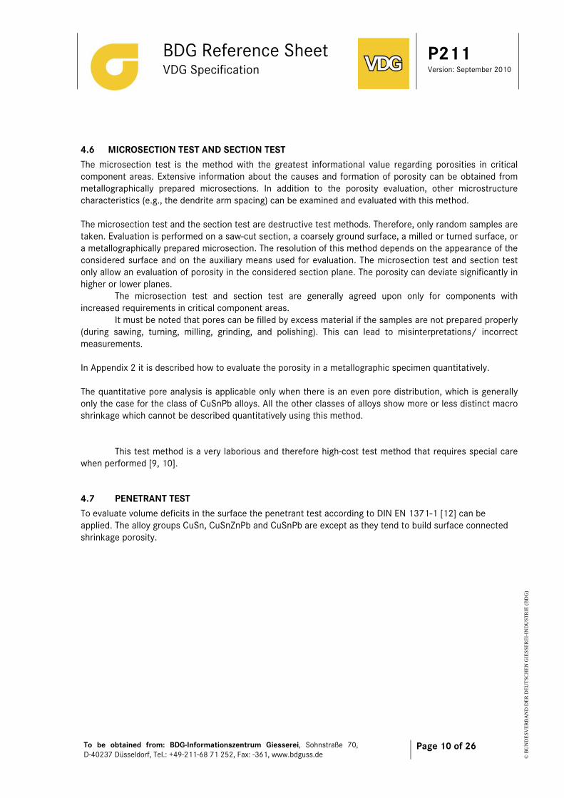
APPENDIX 1.1 COPPER AND COPPER-CHROMIUM ALLOYS Pure copper and copper chromium alloys solidify plane to rough walled. The volume shrinkage during solidification leads to a characteristic pore configuration as shown in figures A 1.1.1 and A 1.1.2.
Figure A 1.1.1
Figure A 1.1.2
1 mm
1 mm
BDG Reference Sheet VDG Specification
P211 Version: September 2010
To be obtained from: BDG-Informationszentrum Giesserei, Sohnstraße 70, D-40237 Düsseldorf, Tel.: +49-211-68 71 252, Fax: -361, www.bdguss.de
Page 13 of 26
© B
UN
DE
SVE
RB
AN
D D
ER
DE
UT
SCH
EN
GIE
SSE
RE
I-IN
DU
STR
IE (
BD
G)
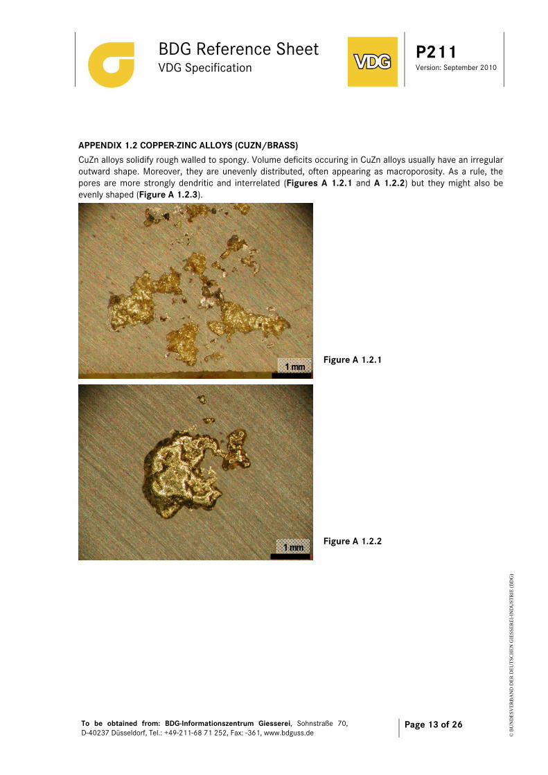
APPENDIX 1.2 COPPER-ZINC ALLOYS (CUZN/BRASS) CuZn alloys solidify rough walled to spongy. Volume deficits occuring in CuZn alloys usually have an irregular outward shape. Moreover, they are unevenly distributed, often appearing as macroporosity. As a rule, the pores are more strongly dendritic and interrelated (Figures A 1.2.1 and A 1.2.2) but they might also be evenly shaped (Figure A 1.2.3).
Figure A 1.2.1
Figure A 1.2.2
1 mm
1 mm

BDG Reference Sheet VDG Specification
P211 Version: September 2010
To be obtained from: BDG-Informationszentrum Giesserei, Sohnstraße 70, D-40237 Düsseldorf, Tel.: +49-211-68 71 252, Fax: -361, www.bdguss.de
Page 14 of 26
© B
UN
DE
SVE
RB
AN
D D
ER
DE
UT
SCH
EN
GIE
SSE
RE
I-IN
DU
STR
IE (
BD
G)
Figure A 1.2.3
1 mm
BDG Reference Sheet VDG Specification
P211 Version: September 2010
To be obtained from: BDG-Informationszentrum Giesserei, Sohnstraße 70, D-40237 Düsseldorf, Tel.: +49-211-68 71 252, Fax: -361, www.bdguss.de
Page 15 of 26
© B
UN
DE
SVE
RB
AN
D D
ER
DE
UT
SCH
EN
GIE
SSE
RE
I-IN
DU
STR
IE (
BD
G)
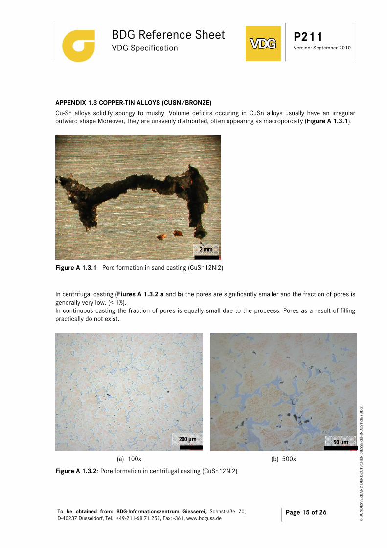
APPENDIX 1.3 COPPER-TIN ALLOYS (CUSN/BRONZE) Cu-Sn alloys solidify spongy to mushy. Volume deficits occuring in CuSn alloys usually have an irregular outward shape Moreover, they are unevenly distributed, often appearing as macroporosity (Figure A 1.3.1).
Figure A 1.3.1 Pore formation in sand casting (CuSn12Ni2)
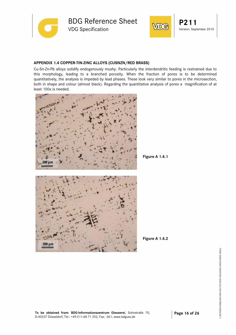
In centrifugal casting (Fiures A 1.3.2 a and b) the pores are significantly smaller and the fraction of pores is generally very low. (< 1%). In continuous casting the fraction of pores is equally small due to the proceess. Pores as a result of filling practically do not exist.
(a) 100x (b) 500x
Figure A 1.3.2: Pore formation in centrifugal casting (CuSn12Ni2)
2 mm
200 µm 50 µm
BDG Reference Sheet VDG Specification
P211 Version: September 2010
To be obtained from: BDG-Informationszentrum Giesserei, Sohnstraße 70, D-40237 Düsseldorf, Tel.: +49-211-68 71 252, Fax: -361, www.bdguss.de
Page 16 of 26
© B
UN
DE
SVE
RB
AN
D D
ER
DE
UT
SCH
EN
GIE
SSE
RE
I-IN
DU
STR
IE (
BD
G)
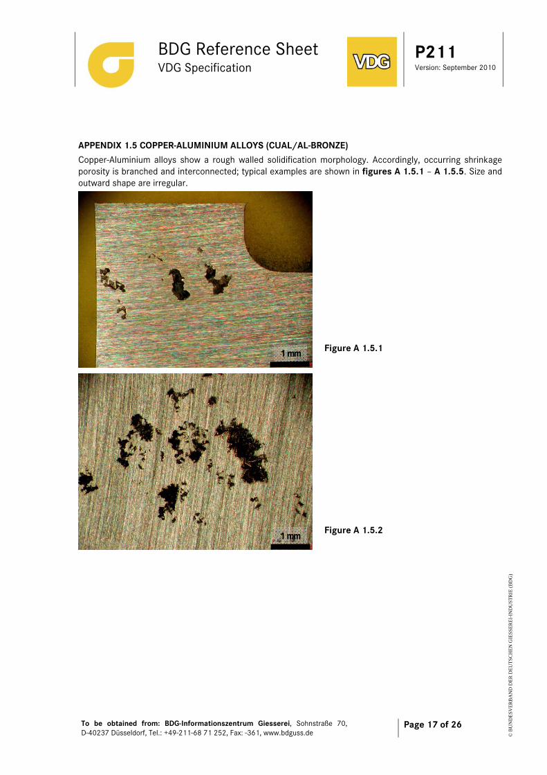
APPENDIX 1.4 COPPER-TIN-ZINC ALLOYS (CUSNZN/RED BRASS) Cu-Sn-Zn-Pb alloys solidify endogenously mushy. Particularly the interdendritic feeding is restrained due to this morphology, leading to a branched porosity. When the fraction of pores is to be determined quantitatively, the analysis is impeded by lead phases. These look very similar to pores in the microsection, both in shape and colour (almost black). Regarding the quantitative analysis of pores a magnification of at least 100x is needed.
Figure A 1.4.1
Figure A 1.4.2
200 µm
200 µm
BDG Reference Sheet VDG Specification
P211 Version: September 2010
To be obtained from: BDG-Informationszentrum Giesserei, Sohnstraße 70, D-40237 Düsseldorf, Tel.: +49-211-68 71 252, Fax: -361, www.bdguss.de
Page 17 of 26
© B
UN
DE
SVE
RB
AN
D D
ER
DE
UT
SCH
EN
GIE
SSE
RE
I-IN
DU
STR
IE (
BD
G)
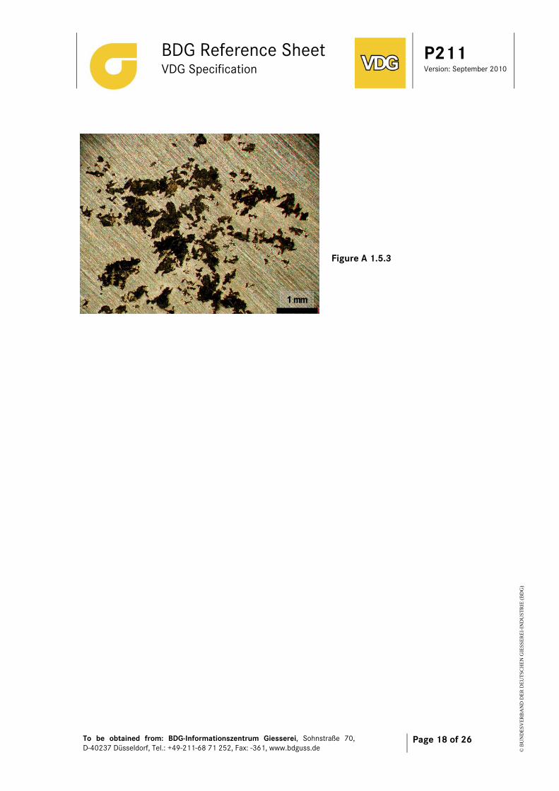
APPENDIX 1.5 COPPER-ALUMINIUM ALLOYS (CUAL/AL-BRONZE) Copper-Aluminium alloys show a rough walled solidification morphology. Accordingly, occurring shrinkage porosity is branched and interconnected; typical examples are shown in figures A 1.5.1 – A 1.5.5. Size and outward shape are irregular.
Figure A 1.5.1
Figure A 1.5.2
1 mm
1 mm
BDG Reference Sheet VDG Specification
P211 Version: September 2010
To be obtained from: BDG-Informationszentrum Giesserei, Sohnstraße 70, D-40237 Düsseldorf, Tel.: +49-211-68 71 252, Fax: -361, www.bdguss.de
Page 18 of 26
© B
UN
DE
SVE
RB
AN
D D
ER
DE
UT
SCH
EN
GIE
SSE
RE
I-IN
DU
STR
IE (
BD
G)
Figure A 1.5.3
1 mm
BDG Reference Sheet VDG Specification
P211 Version: September 2010
To be obtained from: BDG-Informationszentrum Giesserei, Sohnstraße 70, D-40237 Düsseldorf, Tel.: +49-211-68 71 252, Fax: -361, www.bdguss.de
Page 19 of 26
© B
UN
DE
SVE
RB
AN
D D
ER
DE
UT
SCH
EN
GIE
SSE
RE
I-IN
DU
STR
IE (
BD
G)
Appendix 2 – Porosity evaluation by means of microsection testing, section testing and quantitative image analysis Based on experience, the porosity of complex components varies depending on the position of the examined cross sections. The porosity is often not evenly distributed even within a cross-sectional area. The size and shape can vary considerably. For this reason, the description of the porosity for defined section planes through a component is the focus of this reference sheet. To describe the porosity requirements for a component, different pore classes can be defined for partial areas. An orientation regarding which limit porosities are to be agreed upon and complied with can best be achieved if firstly the functional capability of the component is examined and ensured. Based on a component examined in this way, the degrees of porosity present must then be determined in the relevant cross sections and the permissible limit porosities derived from these. The rejection of functionally capable castings due to limit porosities specified too low must be avoided. The resolution of the test method must be considered in the specification of limit porosities. The determination of porosity to be complied with according to this Guideline entails costs for mandatory testing that have to be assessed.
A 2.1 REFERENCE AREAS FOR THE PORE EVALUATION The section planes for documenting compliance with the pore specification of a component must preferably be mutually agreed upon between the caster and the purchaser and must be based on the local loads. They must be defined in the component drawing. In this sense, even machined component areas represent potential section planes. Volumes are evaluated in the radiographic test. For this reason, the following definitions of the cut surface, reference surface, and measuring field/partial surface cannot be used for the radiographic test. Within the section planes, reference areas are defined in which the (quantitative) pore analysis is performed. The position of the reference areas must be selected in such a way that they cover the cross sections that are highly relevant to the functional capability of the component. Under certain circumstances, a very small reference surface may be sufficient if it has to bear exceptional loads and porosities in this area could impair the functional capability. If it is agreed upon that the porosity must be measured using a microscope and quantitative image evaluation (microsection test and section test), then this must be performed at a magnification of 25:1 (20:1 is also possible). Because of the camera resolution on the microscope, square individual measuring fields general cover at most an area of 3 mm x 3 mm. If larger reference areas are defined, the reference areas may have to be divided into several individual measuring fields. In this case, it must be ensured that the individual measuring fields do not overlap, that all measuring fields of a reference area completely cover the reference area, and that the measuring fields have the same size. The reference area must have a square shape. Unless otherwise agreed between the supplier and the purchaser, the square must be sized so that it extends over the entire component wall (adaptation of the reference area to the local component geometry by selecting the largest possible inscribed square). If the selection of a section plane results in annular cut surfaces, the size of the reference surface to be evaluated is based on the thickness of the annulus. This breaks the rule of the maximum inscribed squares. However, a simplified evaluation of the reference area is possible using the quantitative image analysis. The
BDG Reference Sheet VDG Specification
P211 Version: September 2010
To be obtained from: BDG-Informationszentrum Giesserei, Sohnstraße 70, D-40237 Düsseldorf, Tel.: +49-211-68 71 252, Fax: -361, www.bdguss.de
Page 20 of 26
© B
UN
DE
SVE
RB
AN
D D
ER
DE
UT
SCH
EN
GIE
SSE
RE
I-IN
DU
STR
IE (
BD
G)
pore contents can be correctly determined by subtracting the areas of the reference area that do not lie in the casting cross section. If a reference area is not defined in the agreed upon section plane, the reference area must be selected so that it covers the area appearing to have the greatest porosity.
BDG Reference Sheet VDG Specification
P211 Version: September 2010
To be obtained from: BDG-Informationszentrum Giesserei, Sohnstraße 70, D-40237 Düsseldorf, Tel.: +49-211-68 71 252, Fax: -361, www.bdguss.de
Page 21 of 26
© B
UN
DE
SVE
RB
AN
D D
ER
DE
UT
SCH
EN
GIE
SSE
RE
I-IN
DU
STR
IE (
BD
G)
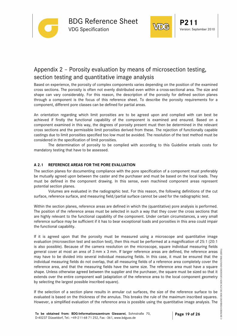
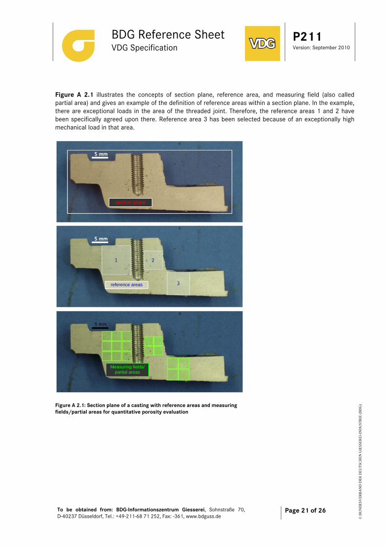
Figure A 2.1 illustrates the concepts of section plane, reference area, and measuring field (also called partial area) and gives an example of the definition of reference areas within a section plane. In the example, there are exceptional loads in the area of the threaded joint. Therefore, the reference areas 1 and 2 have been specifically agreed upon there. Reference area 3 has been selected because of an exceptionally high mechanical load in that area.
Figure A 2.1: Section plane of a casting with reference areas and measuring fields/partial areas for quantitative porosity evaluation
section plane
reference areas
Measuring fields/ partial areas
BDG Reference Sheet VDG Specification
P211 Version: September 2010
To be obtained from: BDG-Informationszentrum Giesserei, Sohnstraße 70, D-40237 Düsseldorf, Tel.: +49-211-68 71 252, Fax: -361, www.bdguss.de
Page 22 of 26
© B
UN
DE
SVE
RB
AN
D D
ER
DE
UT
SCH
EN
GIE
SSE
RE
I-IN
DU
STR
IE (
BD
G)
A 2.2 POROSITY KEY A permissible porosity is specified in the form of a key. This key is composed of several parameters. The type and quantity of parameters can be freely agreed upon, and the parameters can be indicated in any sequence. The designation of the reference sheet is indicated in the first position in the porosity key, followed by a hyphen. The individual parameters follow. A numerical value is placed after each individual parameter. The parameters and the associated values are placed in square brackets. The various parameters are separated from each other by slashes. Example of a porosity key: VDG P211-[Parameter 1][Value]/ [Parameter 2] [Value]/ [Parameter 3] [Value]/ ... /[Parameter n] [Value]
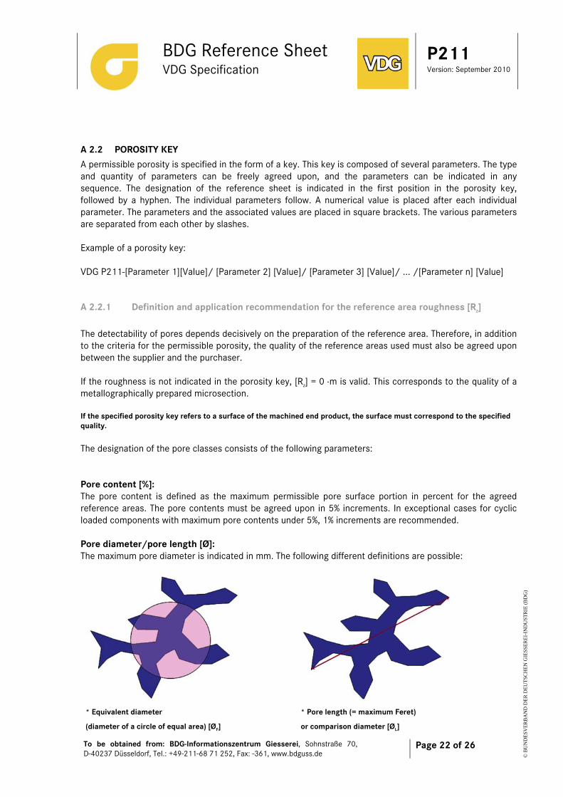
A 2.2.1 Definition and application recommendation for the reference area roughness [Rz] The detectability of pores depends decisively on the preparation of the reference area. Therefore, in addition to the criteria for the permissible porosity, the quality of the reference areas used must also be agreed upon between the supplier and the purchaser. If the roughness is not indicated in the porosity key, [Rz] = 0 μm is valid. This corresponds to the quality of a metallographically prepared microsection. If the specified porosity key refers to a surface of the machined end product, the surface must correspond to the specified quality. The designation of the pore classes consists of the following parameters: Pore content [%]: The pore content is defined as the maximum permissible pore surface portion in percent for the agreed reference areas. The pore contents must be agreed upon in 5% increments. In exceptional cases for cyclic loaded components with maximum pore contents under 5%, 1% increments are recommended. Pore diameter/pore length [Ø]: The maximum pore diameter is indicated in mm. The following different definitions are possible:
* Equivalent diameter
(diameter of a circle of equal area) [ØF]
* Pore length (= maximum Feret)
or comparison diameter [ØL]
BDG Reference Sheet VDG Specification
P211 Version: September 2010
To be obtained from: BDG-Informationszentrum Giesserei, Sohnstraße 70, D-40237 Düsseldorf, Tel.: +49-211-68 71 252, Fax: -361, www.bdguss.de
Page 23 of 26
© B
UN
DE
SVE
RB
AN
D D
ER
DE
UT
SCH
EN
GIE
SSE
RE
I-IN
DU
STR
IE (
BD
G)
If no subscript abbreviation is indicated after the diameter sign, the pore length is always used. Distance of adjacent pores [A]: This parameter indicates the minimum edge distance between two adjacent pores. The distance indication refers to the pore diameter (ØF or ØL) of the smaller of two adjacent pores multiplied by an integer value. The value must be agreed upon by the manufacturer and the purchaser. Note: The distance measurement requires special image analysis software. The use of this parameter is aimed particularly at the specification of mating surfaces. It is practical to use hole templates for a purely visual test. Disregarded pores [U]: This parameter is generally defined for machined mating surfaces. The value of [U] indicates up to which diameter pores are disregarded in the reference area evaluation. Number of pores [Z]: This parameter is generally defined for machined mating surfaces and functional surfaces. The integer value for [Z] specifies the maximum permissible number of individual pores in a reference area. Pore accumulations are treated as individual pores. Pore accumulations [H], [HR], or [HK]: A pore accumulation is existent if the distance between two adjacent pores is less than the diameter of the smaller pore. [H] (without subscript) refers to pore accumulations in the entire reference area
[HR] refers to pore accumulations in the edge area of the reference area (outer third of wall)
[HK] refers to pore accumulations in the core area of the reference area (inner third of wall)
[H], [HR], or [HK] can have the following binary values:
0 = pore accumulations impermissible 1 = pore accumulations permissible
If a maximum pore diameter is defined in addition to the pore accumulation, pore accumulations must be treated as individual pores. This means that if the diameter of an initially permissible pore accumulation exceeds the maximum permissible pore diameter, this pore accumulation is impermissible. Note: It is recommended to make specifications regarding pore accumulations only for mating surfaces and functional surfaces. Localized porosity [N], [NR], or [NK]: There is a localized porosity if the diameter of a pore accumulation exceeds the maximum permissible pore diameter.
BDG Reference Sheet VDG Specification
P211 Version: September 2010
To be obtained from: BDG-Informationszentrum Giesserei, Sohnstraße 70, D-40237 Düsseldorf, Tel.: +49-211-68 71 252, Fax: -361, www.bdguss.de
Page 24 of 26
© B
UN
DE
SVE
RB
AN
D D
ER
DE
UT
SCH
EN
GIE
SSE
RE
I-IN
DU
STR
IE (
BD
G)
[N] (without subscript) refers to localized porosity in the entire reference area
[NR] refers to localized porosity in the edge area of the reference area (outer third of wall)
[NK] refers to localized porosity in the core area of the reference area (inner third of wall) [N], [NR], or [NK] can have the following binary values:
0 = localized porosity impermissible 1 = localized porosity permissible
If [N], [NR], or [NK] is listed in the pore key without a value being indicated, the value 1 automatically applies, i.e., localized porosity is permissible in the corresponding area. Note: It is recommended to make specifications regarding localized porosity only for inner areas of casting walls.
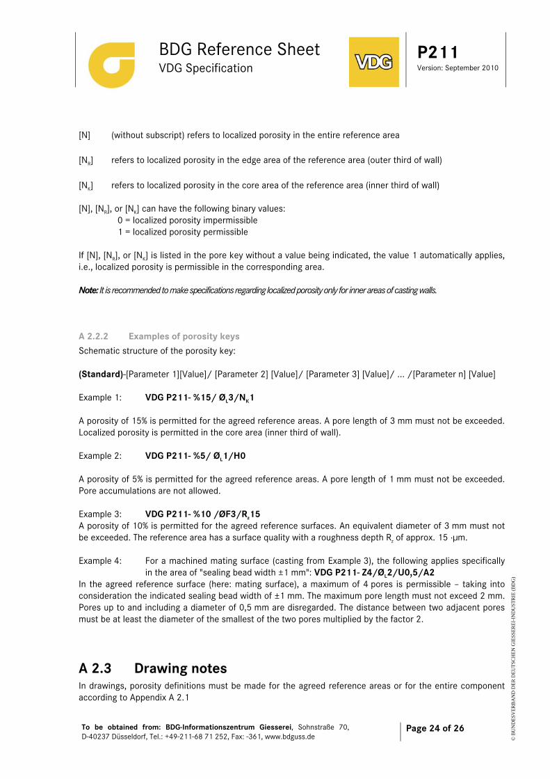
A 2.2.2 Examples of porosity keys Schematic structure of the porosity key: (Standard)-[Parameter 1][Value]/ [Parameter 2] [Value]/ [Parameter 3] [Value]/ ... /[Parameter n] [Value] Example 1: VDG P211- %15/ ØL3/NK1 A porosity of 15% is permitted for the agreed reference areas. A pore length of 3 mm must not be exceeded. Localized porosity is permitted in the core area (inner third of wall). Example 2: VDG P211- %5/ ØL1/H0 A porosity of 5% is permitted for the agreed reference areas. A pore length of 1 mm must not be exceeded. Pore accumulations are not allowed. Example 3: VDG P211- %10 /ØF3/Rz15 A porosity of 10% is permitted for the agreed reference surfaces. An equivalent diameter of 3 mm must not be exceeded. The reference area has a surface quality with a roughness depth Rz of approx. 15 μμm. Example 4: For a machined mating surface (casting from Example 3), the following applies specifically
in the area of "sealing bead width ±1 mm": VDG P211- Z4/ØL2/U0,5/A2 In the agreed reference surface (here: mating surface), a maximum of 4 pores is permissible – taking into consideration the indicated sealing bead width of ±1 mm. The maximum pore length must not exceed 2 mm. Pores up to and including a diameter of 0,5 mm are disregarded. The distance between two adjacent pores must be at least the diameter of the smallest of the two pores multiplied by the factor 2.
A 2.3 Drawing notes In drawings, porosity definitions must be made for the agreed reference areas or for the entire component according to Appendix A 2.1
BDG Reference Sheet VDG Specification
P211 Version: September 2010
To be obtained from: BDG-Informationszentrum Giesserei, Sohnstraße 70, D-40237 Düsseldorf, Tel.: +49-211-68 71 252, Fax: -361, www.bdguss.de
Page 25 of 26
© B
UN
DE
SVE
RB
AN
D D
ER
DE
UT
SCH
EN
GIE
SSE
RE
I-IN
DU
STR
IE (
BD
G)
2.3.1 COLLECTIVE NOTE Collective note means that the pore surface portion refers to any cross sections in the casting. A collective note can be practical if a general minimum porosity level for the entire component required by the design must be defined by the collective note. If required, deviating specifications can be made for special component areas. The reference areas must preferably be defined in mutual agreement between the manufacturer and the purchaser. The collective drawing note is placed near the drawing title block. For collective notes, it must be noted that porosities are strongly cross-section-dependent. In particular for locally limited large wall thickness differences, low pore contents cannot be complied with by casting methods. Accordingly, the limits for the pore contents must be set sufficiently high for a collective note. The rejection of functionally capable castings due to limit porosities specified too low must be avoided.
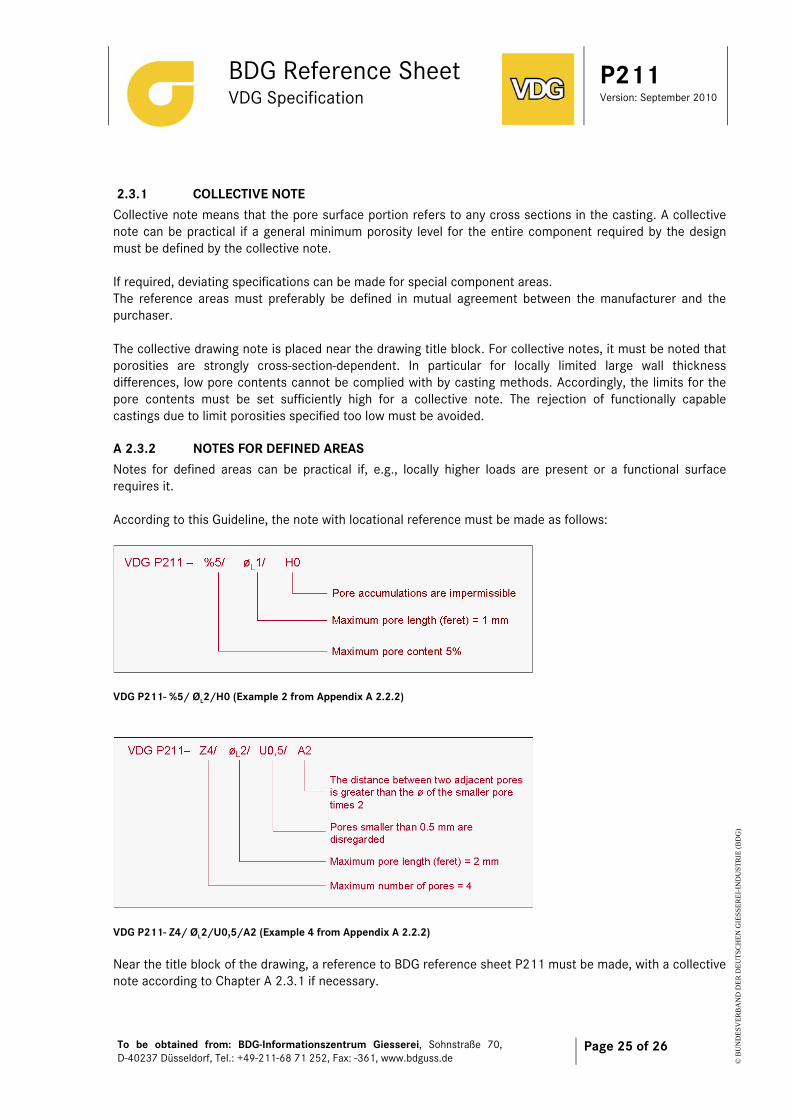
A 2.3.2 NOTES FOR DEFINED AREAS Notes for defined areas can be practical if, e.g., locally higher loads are present or a functional surface requires it. According to this Guideline, the note with locational reference must be made as follows:
VDG P211- %5/ ØL2/H0 (Example 2 from Appendix A 2.2.2)
VDG P211- Z4/ ØL2/U0,5/A2 (Example 4 from Appendix A 2.2.2) Near the title block of the drawing, a reference to BDG reference sheet P211 must be made, with a collective note according to Chapter A 2.3.1 if necessary.
BDG Reference Sheet VDG Specification
P211 Version: September 2010
To be obtained from: BDG-Informationszentrum Giesserei, Sohnstraße 70, D-40237 Düsseldorf, Tel.: +49-211-68 71 252, Fax: -361, www.bdguss.de
Page 26 of 26
© B
UN
DE
SVE
RB
AN
D D
ER
DE
UT
SCH
EN
GIE
SSE
RE
I-IN
DU
STR
IE (
BD
G)
Appendix 3 – Definition of other flaws A 3.1 COLD FLOW MARKS Cold flow marks are patterns representing the borders of different feeding flows on the casting surface. A 3.2 DRAW MARKS Draw marks result from local material removal and look like score marks and scratches on the casting surface (parallel to the mould removal direction). They are caused by friction between the materials when the casting is removed from the mould and when the cores are drawn. A 3.3 BURRS Burrs include casting burrs and burrs resulting from the deformation of material during trim pressing, milling, drilling, etc. Casting burrs are thin-walled material accumulations and metal residues adhering to the casting which result from penetration of the melt in the parting line or in fitting gaps of mould inserts or cores during casting. A 3.4 HEAT CHECK PATTERNS Heat check patterns are characterized by a spider-web-like, raised structure on the casting surface. They result from permanent damage of the permanent mould in the shape of cracks (heat checks). These cracks in the moulds are formed in areas with especially high temperature cycle load. A 3.5 OTHER FLAWS OF CAST COMPONENTS Dimensional deviation, incomplete mould filling, volume variation, distortion, inclusions, ejector marks, flow lines, sink marks, lakes, forced cracks, and spotted surface are other flaws of castings.