voltage tracking of a dc-dc cuk converter using … · voltage tracking of a dc-dc cuk converter...
TRANSCRIPT

i
VOLTAGE TRACKING OF A DC-DC CUK CONVERTER USING
NEURAL NETWORK CONTROL
MOHAMED NOOR AZMAN BIN BIDIN
A project report submitted in partial fulfillment of the requirement for the award of the
Master of Electrical Engineering
Faculty of Electrical and Electronic Engineering
Universiti Tun Hussein Onn Malaysia
JULY, 2012
v
ABSTRACT
This paper presents a control scheme of a neural network for a DC-DC Cuk converter.
The proposed neural network control (NNC) strategy is designed to produce regulated
variable DC output voltage. The mathematical model of Cuk converter and artificial
neural network algorithm is derived. Cuk converter has some advantages compared to
other type of converters. However the nonlinearity characteristic of the Cuk converter
due to the switching technique is difficult to be handled by conventional controller such
as proportional-integral-derivative (PID) controller. To overcome this problem, a neural
network controller with online learning back propagation algorithm is developed. The
NNC designed tracked the converter voltage output and improve the dynamic
performance regardless load disturbances and supply variations. The proposed
controller effectiveness during dynamic transient response is then analyze and verified
using MATLAB-Simulink. Simulation results confirm the excellent performance of the
proposed NNC, exhibits better dynamic performance compared to the classical PID
controller.
vi
ABSTRAK
Kertas ini membentangkan satu skim kawalan jaringan saraf untuk penukar arus terus
(AT-AT) jenis Cuk. Pengawal jaringan saraf yang dicadangkan (NNC) direkabentuk
untuk menghasilkan keluaran voltan AT yang teratur. Model matematik bagi penukar
Cuk dan algoritma jaringan saraf tiruan (ANN) diterbitkan. Penukar Cuk mempunyai
beberapa kelebihan berbanding penukar AT yang lain. Bagaimanapun ciri-ciri
ketidaklelurusan penukar Cuk disebabkan oleh teknik pensuisannya amat sukar
ditangani oleh pengawal konvensional seperti pengawal jenis pembezaan–kamiran-
berkadaran (PID). Untuk mengatasi masalah ini, pengawal jaringan saraf dengan teknik
pembelajaran dalam talian berdasarkan algoritma penyebaran belakang dibangunkan.
Pengawal jaringan saraf yang dibangunkan akan memperbaiki prestasi dinamik tanpa
dipengaruhi oleh perubahan masukan atau gangguan beban. Keberkesanan pengawal
yang dibangunkan semasa sambutan transient dinamik dianalisa dan disahkan
menggunakan simulasi MATLAB-Simulink. Keputusan simulasi mengesahkan prestasi
cemerlang pengawal jaringan saraf yang dibangunkan, mempamerkan prestasi dinamik
yang lebih baik berbanding pengawal konvensional PID.

vii
CONTENTS
TITLE
i
DECLARATION
ii
DEDICATION
iii
ACKNOWLEDGEMENT
iv
ABSTRACT
v
CONTENTS
vii
LIST OF TABLES
x
LIST OF FIGURES xi
LIST OF SYMBOLS AND ABBREVIATIONS
xiii
LIST OF APPENDICES
xv

viii
CHAPTER 1
INTRODUCTION
1
1.1 Project Background 1
1.2 Problem Statement 3
1.3 Project Objectives 4
1.4 Project Scopes 4
1.5 Thesis Organization 5
CHAPTER 2 LITERATURE REVIEW 6
2.1 Controller Development 6
2.2 Cuk converter 8
2.2.1 Cuk converter analysis 9
2.2.1.1 When switch S is ‘on’, 0 < t < DT 10
2.2.1.2 When switch S is ‘off’, DT < t < T 12
2.2.2 Cuk waveforms 13
2.3 Operating Modes 15
2.3.1 Discontinuous Conduction Mode (DCM) 15
2.3.2 Continuous Conduction Mode (CCM) 16
2.3.3 Steady State Operation 17
2.3.3.1 Component selection 17
2.4 Artificial Neural Network (ANN) 21
2.4.1 Back Propagation Algorithm 23
CHAPTER 3 METHODOLOGY 25
3.1 Introduction 25
3.2 Mathematical model 26
3.2.1 State space representations 26
3.2.2 Control–to-output transfer function 32
3.3 The proposed neural network controller for voltage
tracking of a DC-DC Cuk converter
35

ix
CHAPTER 4 RESULT AND ANALYSIS 41
4.1 Simulation results 41
4.1.1 Uncontrolled Cuk converter 41
4.1.2 Cuk converter controlled by PID
controller 46
4.1.3 The proposed NNC controller 47
4.1.4 Voltage tracking of the proposed NNC
controller 48
4.1.5 The output voltage transient response to
reference voltage changes. 52
CHAPTER 5 CONCLUSION AND FUTURE WORK
54
5.1 Conclusion 54
5.2 Future Works 55
REFERENCES 56
APPENDICES 58
x
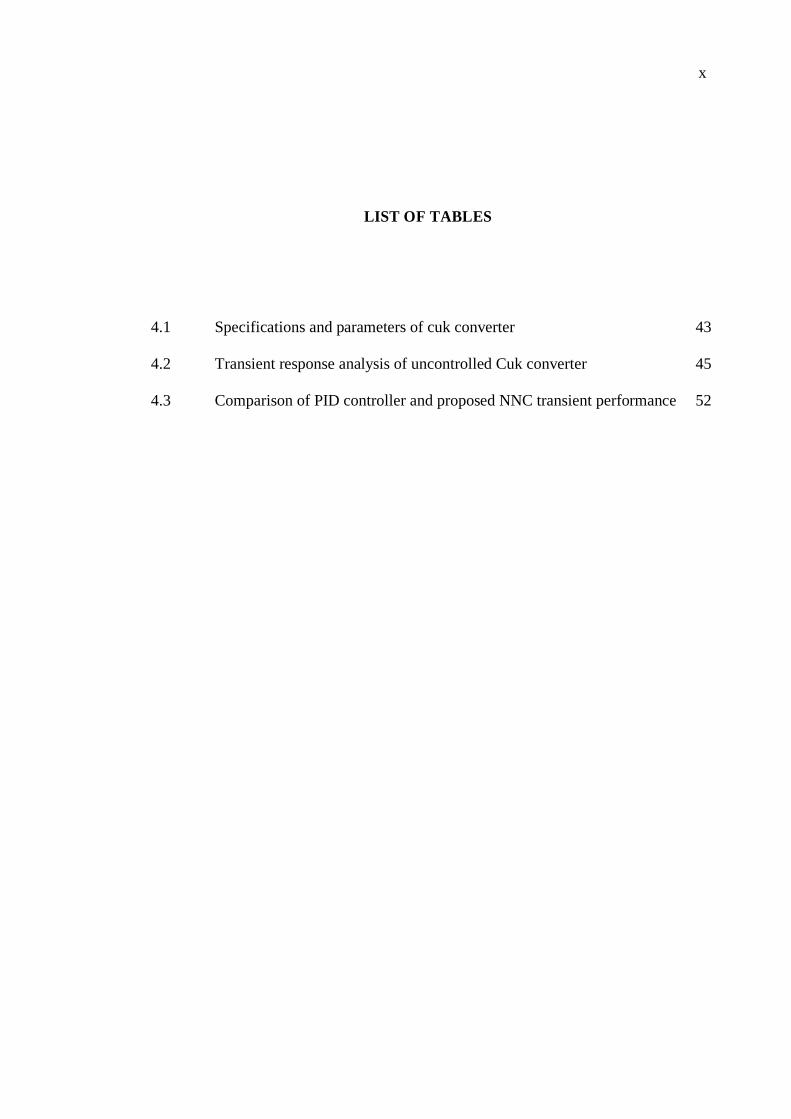
LIST OF TABLES
4.1 Specifications and parameters of cuk converter 43
4.2 Transient response analysis of uncontrolled Cuk converter 45
4.3 Comparison of PID controller and proposed NNC transient performance 52

xi
LIST OF FIGURES
2.1 Cuk converter circuit 9
2.2 Current in inductor L 10
2.3 Cuk converter equivalent circuit when S is on 10
2.4 Cuk converter equivalent circuit when S is off 12
2.5 Cuk converter waveforms 14
2.6 Inductor current waveform of converter: (a) DCM, (b) CCM 17
2.7 Cuk converter waveforms (a) Capacitor current
(b) Capacitor ripple voltage (c) Inductor current
18
2.8 A feed-forward perceptron network with three layers 23
3.1 Block diagram of the proposed NNC of Cuk converter 25
3.2 Cuk converter small signal circuit 26
3.3(a) Mode 1 - switch S is ‘on’ 28
3.3(b) Mode 2 - switch S is ‘off’ 29
3.4 Flow chart of modelled Cuk converter in CCM 34
3.5 Architecture of the proposed neural network controller 35
3.6 Block diagram of proposed NNC with BPA 38
3.7(a) The flow chart of back propagation training process 39
3.7(b) Flow chart of back propagation training process in neural network 40
4.1 Cuk converter simulation diagram 42
4.2 Block diagram of modelled Cuk converter 42
4.3(a) The output voltage transient response when duty cycle, D = 0.25. 43
4.3(b) The output voltage transient response when duty cycle, D = 0.4. 44
4.3(c) The output voltage transient response when duty cycle, D = 0.57 45
4.4 Block diagram of modelled Cuk converter with PID controller 46
4.5 Block diagram of the proposed NNC controller 47
4.6 Block diagram of PID and proposed NNC 48
xii
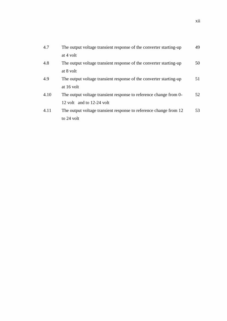
4.7
The output voltage transient response of the converter starting-up
at 4 volt
49
4.8 The output voltage transient response of the converter starting-up
at 8 volt
50
4.9 The output voltage transient response of the converter starting-up
at 16 volt
51
4.10 The output voltage transient response to reference change from 0-
12 volt and to 12-24 volt
52
4.11 The output voltage transient response to reference change from 12
to 24 volt
53
xiii
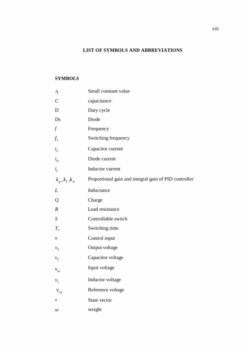
LIST OF SYMBOLS AND ABBREVIATIONS
SYMBOLS
Small constant value
C capacitance
D Duty cycle
Ds Diode
f Frequency
f s Switching frequency
iC Capacitor current
iD Diode current
iL Inductor current
k p , kI ,k d Proportional gain and integral gain of PID controller
L Inductance
Q Charge
R Load resistance
S Controllable switch
TS Switching time
u Control input
v0 Output voltage
vC Capacitor voltage
vin Input voltage
vL Inductor voltage
Vref Reference voltage
x State vector
𝜔 weight

xiv
ABBREVIATIONS
ANN Artificial Neural Network
BPA Back Propagation Algorithm
CCM Continuous Conduction Mode
DC Direct Current
DCM Discontinuous Conduction Mode
EW Error Weight
FNN Feedforward Neural Network
FNNC Fuzzy-Neural Network Controller
FNSM Fuzzy-Neural Sliding Mode
HVDC High Voltage Direct Current
KVL Kirchoff Voltage Law
NNC Neural Network Control
PD Proportional Derivative
PI Proportional Integral
PID Proportional Integral Derivative
PWM Pulse Width Modulation

xv
LIST OF APPENDICES
A Neural Network Programming 58

CHAPTER 1
INTRODUCTION
1.1 Project Background
The role of power conversion is to facilitate the transfer of power from the source to the
load by converting voltages and currents from one magnitude and/or frequency to
another. This function of power processing is performed through an analog power
circuit known as the power converter. A controller is required for the management of
this power transfer process. The ultimate aim of the entire conversion process is to have
as high efficiency as possible, while achieving as closely as possible the desired
conversion and control functions. Reliable and sustainable sources in power electronic
are vital to adhere the continuous power supply.
Basic configurations of DC–DC converters, namely, the buck, boost, buck-
boost, and Cuk converters. Cuk converters are widely used in many industries such as
aerospace, electric trains and modern control in HVDC power supply. Cuk converter has
many advantages which exhibit the characteristics of higher efficiency because of low
input and output current ripple, minimal radio fequency interference, thus resulting

2
smaller in size and weight. In fact, by careful adjustment of the inductor values, the
ripple in either input or output can be nulled completely.
However, operation of the switching devices causes the Cuk converter inherent
the nonlinear characteristics. Nonlinear system requires a controller with higher degree
of dynamic response. In linear system model, the Proportional-Integral-Differential
(PID) controller parameters are easy to determine and resulting good control
performances. PID controllers commonly used in industries because of their simplicity
verified by M.Y.Hassan & G. Khotapali (2010).
A study by Rubaai A., I. Burge & Garuba (2008) shows that PID controller is
unable to adapt and approach the best performance when applied to nonlinear system. It
will sufer from dynamic response, produces overshoot, longer rise time and settling
time which in turn will influenced the output voltage regulation of the Cuk converter. In
order to improve control performance of the Cuk converter, many studies on several
intelligence controllers such as fuzzy logic control have been reported in (Rubaai, A. et
al., 2008) and Evgueniy Entchev & Libing Yang (2007), neural network controller by
(Mahdavi, J. et al., 2005) and hybrid neuro-fuzzy control methods for Cuk converter by
K. Mehran, D. Giaouris & B. Zahawi (2010). Furthermore, the implementations of the
neural network control (NNC) have been proposed recently in (Utomo, W. et al., 2011).
In addition, the NNC also have been applied for several power sources
applications such as solar photovoltaic (PV) modules with voltage tracking properties.
A study by M. Vaigundamoorthi & R. Ramesh (2011) shows that Cuk converter
resulting in high conversion efficiency at high-frequency operation, improved transient,
steady state response without significant increase in voltage and current stresses on
switches.
Some researchers have developed learning back propagation scheme to improve
the effectiveness of nonlinear system. A study by (Utomo, W. et al., 2011) shows that
learning back propagation scheme improves the performance of the NNC by improving
the dynamic response and minimizing the steady state error.
In this project, neural network controller (NNC) scheme with back propagation
algorithm is proposed for the voltage tracking of a DC-DC Cuk Converter using
MATLAB Simulink. The developed NNC reacted as an adaptive controller that has an
3
ability to learn instantaneously and updated the control parameters based on external
disturbance and internal variation of the converter with minimum steady state error,
overshoot and rise time of the output voltage.
1.2 Problem Statement
Most of the common DC-DC converters such as Buck, Boost and Buck-Boost converter
which is capable to step-up or step-down the output voltage produce higher current
ripple. This will influenced and decreased the output voltage regulation and efficiency
of the converter. These weaknesses can be overcomed by Cuk converter which exhibit
low input and low output current ripple. Thus the efficiency of the converter will be
increased. These factors will contribute to minimise the radio fequency interference,
thus the converter size becomes smaller and lighter (compact).
However the switching technique of the Cuk converter causes the converter
system to be nonlinear system. Nonlinear system requires a controller with higher
degree of dynamic response. Proportional-Integral-Differential (PID) controllers has an
advantages in term of simple structure and low cost. However, PID controllers unable to
adapt to the external disturbances and internal variations parameters and suffer from
dynamic response of the system. PID controllers will produce higher overshoot, longer
rise time and settling time which in turn will decreased the output voltage regulation of
the Cuk converter.
Since the Cuk converter is a nonlinear system, the neural network control
(NNC) method will be developed to improve the voltage tracking of the converter. The
developed NNC has the ability to learn instantaneuously and adapt its own controller
parameters based on external disturbances and internal variation of the converter. Thus
this NNC can overcome the problems stated to obtain the required output voltage with
better performances; decreasing overshoot and oscillation, faster rise time, faster
settling time and minimised steady state error of the system.
4
1.3 Project Objectives
The objectives of this project are;
i. To model and analyse a DC-DC Cuk converter and simulate using MATLAB
Simulink.
ii. To develop voltage tracking of a DC-DC Cuk converter using Neural Network
Control (NNC) method.
iii. To analyze the impact of Neural Network Controller (NNC) on voltage tracking
DC-DC Cuk converter performances (reducing over shoot, rise time and steady
state error).
1.4 Project Scopes
The scopes of this project is to simulate the proposed method of voltage tracking of
non-isolated Cuk converter by using Neural Network Controller (NNC) with MATLAB
Simulink software. The proposed NNC architecture with 1-3-1 neurons structure; the
input layer consists of input neurons, three neurons at the hidden layer followed by an
output layer. Analysis of the converter will be done for continuous current mode (CCM)
only. Analysis in this mode of operation use a state-space averaged model of the Cuk
converter with small signal analysis. The PID controller will be developed to compare
the effectiveness of the proposed controller.

5
1.5 Thesis Organization
This thesis is organized as follows: Chapter 2 discusses the basic concept of a Cuk
converter and describes the development of dynamic modelling. An introduction to
concept and design of learning back propagation algorithm of neural network control is
also detailed. Mathematical model of the Cuk converter is derived in Chapter 3 and the
proposed Neural Network Controller for voltage tracking of a DC-DC Cuk converter is
developed. Chapter 4 shows the simulation results of the NNC controller and the
dynamical responses. Finally, conclusions are summarized in Chapter 5.

CHAPTER 2
LITERATURE REVIEW
2.1 Controller Development
Switching control techniques of the nonlinear DC-DC converter has been great issues in
power conversion system. Usually, the control problem consists in defining the desired
nominal operating conditions and regulating the circuit so that it stays close to the
nominal, when the system is subject to external disturbances and internal variations.
Modeling errors also can cause its operation to deviate from the nominal value. Many
approaches for designing controller for Cuk converter has been deeply studied and
conducted to obtain high quality and reliable power conversion system.
In the past decade, basically switching control enlightened towards the
applications of Proportional-Integral (PI); enhanced to Proportional-Integral-Derivative
(PID) controllers. A study by A.J. Forsyth and S.V. Mollow (1998) shows that these
classical control methods are very efficient when the converter model is well-known; the
working-point of the load is well defined. If the dynamics of the whole converter is
more complex, varying and/or uncertain, advanced control laws have to be introduced.

7
The controller must keep the DC-DC converter within a certain percentage of the
specified nominal operating points in the presence of disturbances and modeling errors.
Unfortunately, PID controller does not always fulfill the above mentioned
control specifications, especially when disturbance rejection and transient response time
requirements are concerned, due to the highly nonlinear characteristics of the converter.
PID will suffer from dynamic transient time response; higher overshoot and longer rise
time reported by Loic Michel, I. Cedric Join and Michel Fliess (2010).
A large number of possible intelligence controllers among others, fuzzy logic
control, neural network control and hybrid neuro-fuzzy control have been reported in M.
Milanovic and D. Gleich (2005). Many types of controllers have been proposed on the
previous papers.
By referring to the (K.H. Cheng, et al., 2007), the research focused on an
efficient simulation model of Cuk converter by applying the fuzzy-neural sliding mode
control (FNSM) as the controller. The simulation model of FNSM developed improved
the dynamic characteristics of Cuk converter. The fuzzy logic controller is designed
purposely to ensure the converter system is able to reach the steady state condition in a
short time. The result obtained from fuzzy logic controller will compared with the PID
controller. The result shows that the fuzzy logic controller is better performance
compared with PID controller.
Development of Proportional-Derivative and Integral (PD-I) type Fuzzy-Neural
Network Controller (FNNC) based on Takagi-Sugeno fuzzy model is proposed for Cuk
converter to achieve satisfied performance under steady state and transients conditions
presented in (K. Mehran. et al., 2010). The PD-FNNC is activated during transient states
and the PI-FNNC is activates in steady state region.
After the pioneering studies done by (Loic Michel, et al., 2010), a great deal of
research has been directed at developing techniques for averaged modeling of different
classes of switching converters (S.R. Sanders, et al., 2009) and for an automatic
generation of the averaged models. The motivation of such studies was the simplest
possible selection of continuous models adequate to capture all the main features of the
switching converters in term of stability, dynamic characteristics, and effectiveness of
the design.
8
Rapid technologies discover intelligent controls of neural network controllers (NNC)
has great capability to adapt by updating its learning process using back propagation and
sensitivity adjustment. Therefore it is suitable for nonlinear control system. NNC found to
be improving the dynamic characteristic of the converter compared with the conventional
method. Voltage tracking of Cuk converter using NNC demonstrates the results in achieving
the minimum error between regulated DC output voltage and reference voltage injected to
the system. This has been verified in (Utomo, W. et al., 2011). From the simulation
results, it shows that when the proposed NNC is trained with back propagation
algorithm, the overshoot has been greatly decreased and the Cuk converter output
voltage can reach its steady state faster. In the case of load disturbances, the NNC can
shorten the settling time compared with ordinary PID control with a better tracking
performance.
2.2 Cuk converter
The Cuk converter is a type of step-down/step-up converter based on a switching boost-
buck topology. Essentially, the converter is composed of two sections, an input stage
and an output stage. The schematic of the Cuk converter is presented in Figure 2.1,
where Vin is input voltage source, Vo is output voltage, input inductor L1, controllable
switch S, energy transfer capacitor C1, diode D1, filter inductor L2, filter capacitor C2,
and load resistance R. An important advantage of this topology is a continuous current at
both the input and the output of the converter. Disadvantages of the Cuk converter are a
high number of reactive components and high current stresses on the switch, the diode,
and the capacitor C1.

9
Figure 2.1: Cuk converter circuit
2.2.1 Cuk converter analysis
Analysis for Cuk converter operation using a state-space averaged model developed as
described by the inventor, Slobodan M., Cuk, 1977. These analyses involve the use of
steady-state and dynamic small signal models of the converter to determine the
responses of the converter when operating in the operational continuous current mode
(CCM). In the subsequent, parasitic resistances are negligibly small, and all elements are
assumed ideal. During the operation, the switch S switches on and off by an externally
applied control signal at a switching frequency „fS‟, and duty ratio „D‟ within the period T.
CCM operation implies that inductor currents do not fall to zero at any instant within the
period. The operation of the converter within the period T can be divided into two states for
CCM operation where duty cycle of the converter is D = Ton /T and D‟ = 1 – D.

10
Figure 2.2: Current in inductor L
2.2.1.1 When switch S is ‘on’, 0 < t < DT
In the state switch S is on, the converter circuit takes the form shown in Figure 2.3.
There are two separate meshes. In the left hand mesh the input inductor L1 stores energy
from the source over S during the time interval. The energy storage capacitor C1 is now
in the right hand mesh and it transfers stored energy, over S, to the load R, and energy
storing elements L2 and C2. Due to the inappropriate voltage polarity of the charge on
the capacitor C1, diode D1 is reverse biased and therefore off. The common path between
the two meshes is provided by switch S this time.
Figure 2.3: Cuk converter equivalent circuit when S is on

11
In the left hand mesh,
In the right hand mesh,
The current through capacitor C2,
Current passing through S is the sum of input and output inductor currents:

12
2.2.1.2 When switch S is ‘off’, DT < t < T
The circuit is divided into two separate meshes as seen in Figure 2.4. When S is off, the
energy storage capacitor C1 in the left hand mesh is charged through L1 and D1 in this time
interval. Diode D1 common to both meshes is forward biased in this time interval. L2 and C2
in the right hand mesh transfer their stored energies, left from the previous time interval
during the steady-state operation, to the load R over D1 again.
Figure 2.4: Cuk converter equivalent circuit when S is off
In the left hand mesh, by applying KVL;
13
The current through capacitor C1,
In the right hand mesh, by applying KVL;
The current through capacitor C2,
Current passing through D1 is the sum of input and output inductor currents:
2.2.2 Cuk waveforms
Based on the equations derived during the switching intervals, off and on state, the main
waveforms of the voltage across inductor and
and capacitor current and
of Cuk converter are presented in Figure 2.5. (Rashid, 2004).
14
Figure 2.5: Cuk converter waveforms
In steady state, the transfer function can be determined by average current
through capacitor in one period is zero. Therefore, by solving the linear equation during
turn-on and turn-off, the average output voltage is derived as follows;
[ ]DT + [ ]
DT +

15
Combining equation (2.12 and (2.13), the relationship of output-input voltage
function yields the transfer function as follows;
Rearrange the transfer function equation in (2.14), the Cuk converter output
voltage, can be determined as;
The negative sign indicates a polarity reversal between output and input.
Based on equation (2.15), it is obviously shown that the output voltage of this
converter is regulated according to the duty cycle (D) of the PWM input at fixed
frequency. When the duty cycle (D) is less than 0.5, the output voltage of the converter
is lower than the input voltage (step-down). If the duty cycle (D) is greater than 0.5, the
output voltage of the converter is higher than the input voltage (step-up).
2.3 Operating Modes
The operation of DC-DC converters can be classified by two modes of operation:
discontinuous current mode (DCM) and continuous current mode (CCM). In the
DCM, the inductor current falls to zero during the time the switch is turned off. In the
CCM, the current flowing through the inductor never falls to zero. A converter
can be design in any mode of operation according to the requirement.
2.3.1 Discontinuous Conduction Mode (DCM)
When the inductor current has an interval of time staying at zero with no charge and
discharge then it is said to be working in discontinuous conduction mode
(DCM) operation and the waveform of inductor current is illustrated in Figure
2.5(a). At lighter load currents, converter operates in DCM. The regulated output

16
voltage in DCM does not have a linear relationship with the input voltage as in
CCM. In DCM, each switching cycle is divided into of three parts that is
and During the third mode i.e in inductor current stays at zero.
2.3.2 Continuous Conduction Mode (CCM)
When the inductor current flow is continuous of charge and discharge during a
switching period, it is called continuous conduction mode (CCM). The inductor
current waveform of CCM shown in Figure 2.5(b). The converter operating in CCM
delivers larger current than in DCM. In CCM, each switching cycle consists of two
parts that is and . During inductor current increases linearly and then
in it decreases linearly. In this thesis, only operation in the CCM is analysed.
Figure 2.6: Inductor current waveform of converter: (a) DCM, (b) CCM

17
2.3.3 Steady State Operation
Steady-state operation requires that the inductor current at the end of the switching cycle
be the same as that at the beginning, meaning that the net change in inductor current
over one period is zero.
2.3.3.1 Component selection
It is a vital task to select the minimum value of components to ensure that the converter
operates in CCM. In the preceding analysis, the capacitor was assumed to be very large
to keep the output voltage constant. In practice, the output voltage cannot be kept
perfectly constant with a finite capacitance. The variation in output voltage, or ripple, is
computed from the voltage-current relationship of the capacitor. The current in the
capacitor is;
The average voltage across C2 is computed from KVL around the outermost
loop. The average voltage across inductors is zero for steady-state operation, resulting in
While the capacitor current is positive, the capacitor is charging. From the definition of
capacitance,
The change in charge is the area of the triangle above the time axis as
shown in Figure 2.7.

18
Figure 2.7: Cuk converter waveforms (a) Capacitor current
(b) Capacitor ripple voltage (c) Inductor current
(
) (
)
resulting in
Substiting into equation (2.22) yields;

19
Since
, equation (2.24) can be rearranged as;
In this equation, is the peak-to-peak ripple voltage at the output, as shown in
Figure 2.6 (b). The output voltage ripple is the ripple on the voltage of the capacitor C2.
It is also useful to express the ripple as a fraction of the output voltage,
In design, it is useful to rearrange the preceding equation to express required
capacitance in terms of specified voltage ripple,
Then ripple in can be estimated by computing the change in in the
interval when the switch is open and the currents and
are the same. Assuming
the current in to be constant at a level
∫
(
)
Then fluctuations in inductor currents can be computed by examining the
inductor voltage while the switch is close. The voltage across with the switch close
is;
20
In the time interval DT when the switch is closed, the change in inductor current
is;
For inductor the voltage across it when the switch is closed is;
The change in is then;
For continuous current in the inductors, the average current must be greater than
one-half the change in current. Minimum inductor sizes for continuous current are;

21
2.4 Artificial Neural Network (ANN)
An artificial neural network (ANN), usually called neural network (NN), is a type of
artificial intelligence technique that mimics the behavior of human brain. It can
approximate a nonlinear relationship between the input and outputs variables of
nonlinear, complex system without requiring explicit mathematical representations. In
other word, it duplicate the mathematical model or computational model that inspired
by the structure and/or functional aspects of biological nervous system, such as brain,
process information (neural networks). A neural network consists of an interconnected
group of artificial neurons, and it processes information using a connectionist approach
to computation. In most cases an ANN is an adaptive system that changes its structure
based on external or internal information that flows through the network during the
learning phase.
Modern neural networks are non-linear statistical data modeling tools. They are
usually used to model complex relationships between inputs and outputs or to find
patterns in data. It is composed of a large number of highly interconnected processing
elements working in unison to solve specific problems. Each of these processing
elements, known as neuron, has a number of internal parameters called weights ( .
Changing the weights of a neuron alters not only the behavior of the neuron, but the
behavior of the entire network. Hence, by means of a training process, the weight of
each neuron is self-tuned to achieve a desired input-output relationship.
Feedforward Neural Networks (FNN‟s) are widely used to solve complex
problems in pattern classification, system modeling and identification, and nonlinear
signal processing. It is known that the learning process of a FNN is characterized by the
rate of convergence to a solution and the possibility to reach an optimal solution.

22
Figure 2.8 illustrates a Feed-forward Multilayer Perceptron Neural Network
architecture. “Feed forward” means that the values only move from input to hidden to
output layers; no values are fed back to earlier layers. All neural networks have an input
layer and an output layer, but the number of hidden layers may vary.
This network has an input layer ( , one hidden layer and an output layer ( ; all
with three neurons.
Figure 2.8: A feed-forward perceptron network with three layers
At the input Layer, a vector of predictor variable values (x1...xp) is presented to
the input layer. The input layer (or processing before the input layer) standardizes these
values so that the range of each variable is -1 to 1. The input layer distributes the values
to each of the neurons in the hidden layer. In addition to the predictor variables, there is
a constant input of 1.0, called the bias that is fed to each of the hidden layers; the bias is
multiplied by a weight and added to the sum going into the neuron. Arriving at a neuron
in the hidden layer, the value from each input neuron is multiplied by a weight (wji), and
the resulting weighted values are added together producing a combined value uj.

23
The weighted sum (uj) is fed into a transfer function, σ, which outputs a value hj.
The outputs from the hidden layer are distributed to the output layer. Arriving at a
neuron in the output layer, the value from each hidden layer neuron is multiplied by a
weight (wkj), and the resulting weighted values are added together producing a combined
value vj. The weighted sum (vj) is fed into a transfer function, σ, which outputs a value
yk. The y values are the outputs of the network. Therefore, the main advantage of
applying the ANN in the control of DC-DC converters lies in its intrinsic capabilities to
learn and reproduce highly nonlinear transfer function that enables the control to be done
effectively for small and large signal conditions.
2.4.1 Back Propagation Algorithm
In order to train a neural network to perform some task, we must adjust the weights of
each unit in such a way the error between the desired output and actual output is
reduced. This process requires that the neural network compute the error derivative of
the weights (EW). In other word, it must calculate how the error changes as each weight
is increased or decreased slightly. The back propagation algorithm (BPA) is the most
widely used method for determining the EW.
Back Propagation Algorithm (BPA) is also known as generalized delta rule. BPA
is based on the gradient descent optimization technique. As mentioned earlier, the NN
proposed contains three layers; input, hidden and output layers. During the training
phase, the training data is fed into the input layer. The data is propagated to the hidden
layer and then to the output layer. This is called the forward pass of the BPA. In forward
pass, each node in hidden layer gets input from all the nodes from input layer, which are
multiplied with appropriate weights and then summed. The output of the hidden node is
the non-linear transformation of the resulting sum. Similarly each node in output layer
gets input from all the nodes from hidden layer, which are multiplied with appropriate
weights and then summed. The output of this node is the non-linear transformation of
the resulting sum.

24
The output values of the output layer are compared with the target output values.
The target output values are those that we attempt to teach our network. The error
between actual the output values and target output values is calculated and propagated
back toward hidden layer. This is called the backward pass of the BPA. The error is
used to update the strengths between nodes, i.e weight matrices between input-hidden
layers and hidden-output layers are updated.
56
REFERENCES
A.J. Forsyth and S.V. Mollow (1998). Modeling and control of DC-DC converters,
IEEE Power Engineering Journal, vol. 12, pp.229-236.
Loic Michel, I. Cedric Join, Michel Fliess (2010). Model-free control of dc/dc
converters. 12th
IEEE Workshop on Control and Modeling for Power
Electronics (COMPEL).
Mahdavi J., Nasiri M.R., Agah A and Emadi A, (2005). Application of neural
network and State space averaging to DC-DC PWM converters in sliding-mode
operation. IEEE Transaction on Mechatronics, vol. 10, no.1. pp.60-67.
W.M. Utomo, A.A.Bakar, M.Z. Ahmad (2011). Online Learning Neural Network
Control of a DC-DC Buck-Boost Converter. 8th
International Conference on
Information Technology- New Generations, Las Vegas, Nevada, USA.
W.M. Utomo, Z.A. Haron, A.A.Bakar, M.Z. Ahmad and Taufik (2011). Voltage
tracking of a DC-DC Buck-Boost Converter Using Neural Network Control.
International Journal of Computer Technology and Electronics Engineering,
vol. 1, issue 3.
Evgueniy Entchev, Libing Yang (2007). Application of adaptive neuro-fuzzy
inference system techniques and artificial neural networks performance.
Journal of Power Sources 170.
Rubaai, A., A.R, I. Burge and Garuba (2008). Hardware Implementation of an
adaptive network-based fuzzy controller for DC-DC Converters. IEEE
Transaction On Industrial Applications, vol. 41, No.6, pp. 1557–1565.
K. Mehran, D. Giaouris and B. Zahawi (2010). Modeling and stability analysis of
closed loop current-mode Cuk converter using takagi-Sugeno fuzzy approach.
IEEE Conference on Intelligence Systems and Knowledge Engineering.
57
A.Balestrino, A. Landi and L.Sani (2002). Cuk converter global control via fuzzy
logic and scaling factors. IEEE Transaction On Industrial Applications, vol. 38,
No.2, pp. 406-413.
M.Y. Hassan and G.Kothapali (2010). Comparison between neural network based PI
and PID controllers. 7th
International Multi-Conference on systems, Signals
and devices.
M. Vaigundamoorthi & R. Ramesh (2011). ZVS-PWM Active-Clamping Modified
Cuk Converter Based MPPT for Solar PV Modules. European Journal of
Scientific Research Vol. 58, No.3, pp. 305-315.
Kuo-Hsiang Cheng, Chun-Fei Hsu, Chih-Min Lin, Tsu-Tian Lee and Chunshien Li
(2007). Fuzzy-Neural Sliding-Mode Control for DC-DC Converters Using
Asymmetric Gaussian Membership Functions IEEE Transaction on Industrial
Electronics, vol. 54, no.3. pp.1528-1536.
M. Milanovic, and D. Gleich (2005). Buck Converter Digitally Controlled by A
Fuzzy State-space Controlled, HAIT Journal of Science and Engineering B.,
vol. 2, issue 5-6, pp 638-654,
S.R. Sanders, J.M.Noworolsky, X.Z. Liu and G.C. Verghese (2009). Generalized
averaging method for power conversion circuits. IEEE Trans. Power Electron,
vol. 6, no.1. pp.251-259.
Cuk, Slobodan M. (1977). Modeling, Analysis and Design of Switching Converters,
Ph.D. Theses, California Institude of Technology, Pasadena, California,.
Middlebrook R.D., Cuk Slobodan (1976). A General Unified Approach to Modeling
Switching Converter Power Stages. IEEE Power Electronics Specialist
Conference, pp. 73-86, Cleveland.