volkswagen passat b6 2005 - b6 · 2016-03-29 · volkswagen passat b6 2005 - > (b6) ... in the...
TRANSCRIPT
VAS 5051 / 5052
General information
All service and On Board Diagnostic (OBD) program procedures (for example: "adaptation" , "coding" , "Output Diagnostic Test Mode (DTM)" etc. mentioned in this repair manual must be performed using either the VAS 5051 Vehicle Diagnostic Testing and Information System, VAS 5052 Diagnostic and Service System or any subsequent VAS 50 series tester variants (i.e.: VAS 5051B, VAS 5053 etc.).
Specific service, On Board Diagnostic (OBD) and component / function troubleshooting procedures are available via tester operating modes "Guided Fault Finding" or "Guided Functions".
Read, understand and observe Scan Tool (ST) and Test Equipment, safety precautions 97-1, Scan Tool (ST) and Test Equipment, safety precautions
- VAS 5051 / 5052, connecting 97-1, Vehicle Diagnostic, Testing and Information System VAS 5051/5052 , connecting and selecting functions .
Note:
Additional information:
Self Study Program - Course Number 811203 "VAS 5052 Design and Function"
VAS 5051 / VAS 5052 Operating instructions
VAS 5051 / VAS 5052 Operating mode "Administration" .
Electrical Wiring Diagrams, Troubleshooting and Component Locations binder
Scan Tool (ST) and Test Equipment, safety precautions
Warning!
Due to weight, size and need for manual operation of test instruments while vehicle is driven on public roads, instrument must be used only with a Driver operating the vehicle and an Instrument Operator operating the test equipment.
Volkswagen Passat B6 2005 - >(B6)
Do not use Instrument with Driver only. Always use two persons to conduct test.
Do not place Instrument on lap of Driver or front seat passenger because emergency stop may dislodge Instrument and cause airbag deployment with risk of injury to Instrument Operator.
Place Instrument in rear seating area and secure by available safety belt.
Instrument Operator must be seated in the other rear seating position, after sliding front passenger seat and moving the seat back as far forward as possible. Do not activate the seat back release lever.
Instrument Operator must wear safety belt.
Vehicle Diagnostic, Testing and Information System VAS 5051/5052 , connecting and selecting functions
Warning!
Always read, understand and observe Scan Tool (ST) and Test Equipment safety precautions 97-1, Scan Tool (ST) and Test Equipment, safety precautions
Note:
Refer to tester operating instructions by connecting tester and selecting "Administration" and "Operators Handbook" .
Special tools, testers and auxiliary items required
Стр. 2 из 4VAS 5051 / 5052
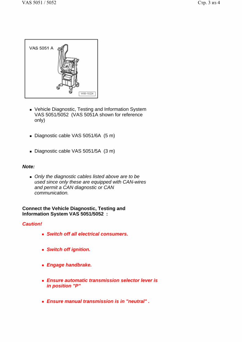
Vehicle Diagnostic, Testing and Information System VAS 5051/5052 (VAS 5051A shown for reference only)
Diagnostic cable VAS 5051/6A (5 m)
Diagnostic cable VAS 5051/5A (3 m)
Note:
Only the diagnostic cables listed above are to be used since only these are equipped with CAN-wires and permit a CAN diagnostic or CAN communication.
Connect the Vehicle Diagnostic, Testing and Information System VAS 5051/5052 :
Caution!
Switch off all electrical consumers.
Switch off ignition.
Engage handbrake.
Ensure automatic transmission selector lever is in position "P"
Ensure manual transmission is in "neutral" .
Стр. 3 из 4VAS 5051 / 5052
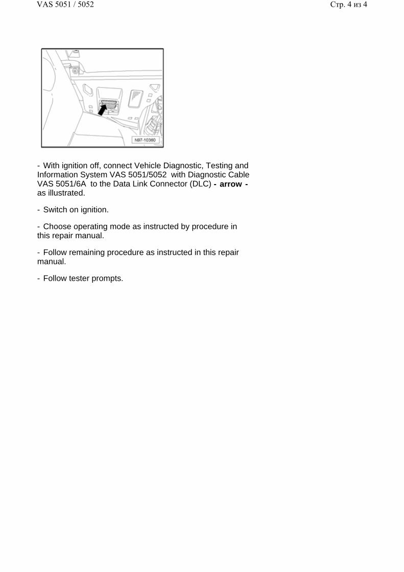
- With ignition off, connect Vehicle Diagnostic, Testing and Information System VAS 5051/5052 with Diagnostic Cable VAS 5051/6A to the Data Link Connector (DLC) - arrow - as illustrated.
- Switch on ignition.
- Choose operating mode as instructed by procedure in this repair manual.
- Follow remaining procedure as instructed in this repair manual.
- Follow tester prompts.
Стр. 4 из 4VAS 5051 / 5052
97 - 2
Fuse Panels
Fuse panel, removing and installing
Note:
In the Passat, there are two fuse panels installed, located at left and right on instrument panel.
The following illustration depicts procedure for removing the "left fuse panel" . Work procedure for removing right fuse panel is the same.
Caution!
When disconnecting and reconnecting battery terminals, observe all applicable Notes and torque specifications, as well as instructions on performing OBD program and electrical system function checks as specified in this Repair Manual 27-4, Battery, disconnecting and reconnecting .
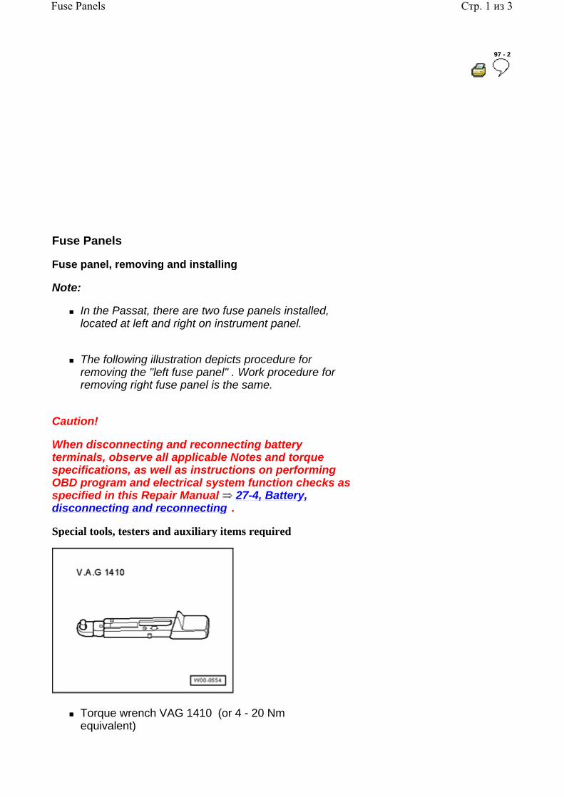
Special tools, testers and auxiliary items required
Torque wrench VAG 1410 (or 4 - 20 Nm equivalent)
Стр. 1 из 3Fuse Panels
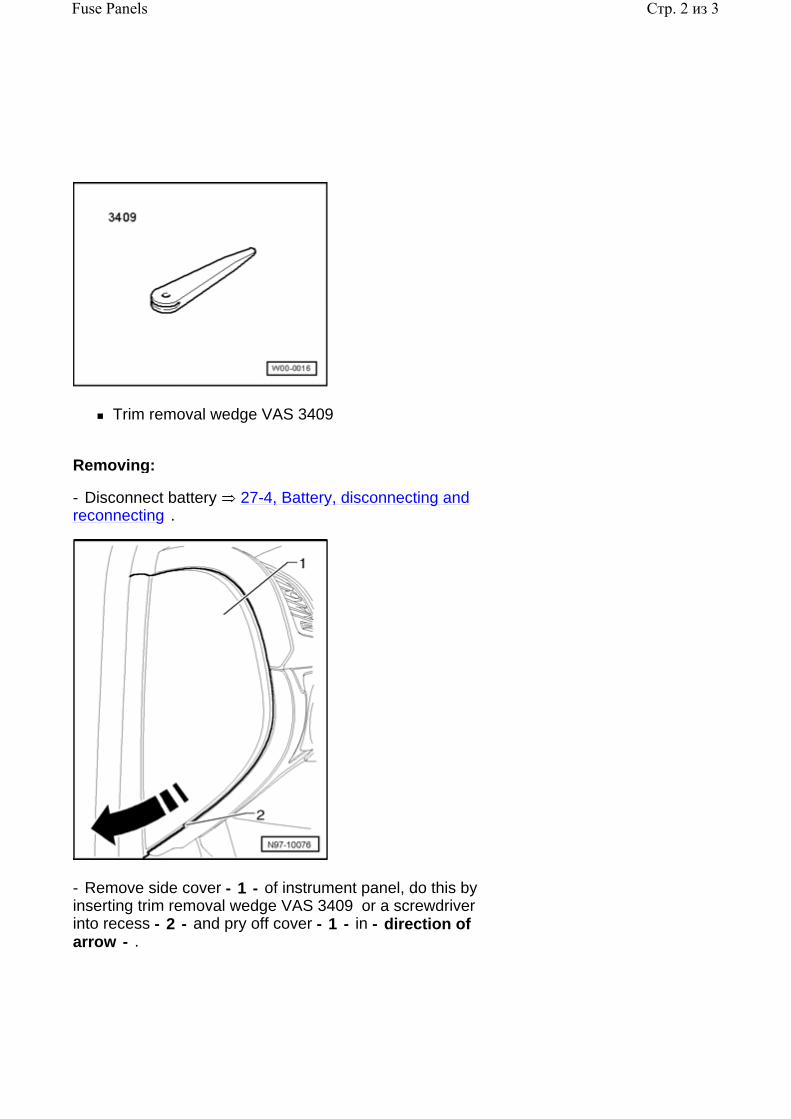
Trim removal wedge VAS 3409
Removing:
- Disconnect battery 27-4, Battery, disconnecting and reconnecting .
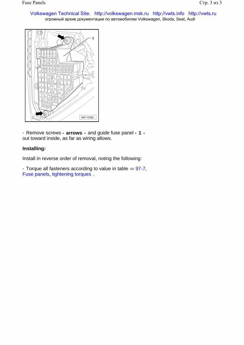
- Remove side cover - 1 - of instrument panel, do this by inserting trim removal wedge VAS 3409 or a screwdriver into recess - 2 - and pry off cover - 1 - in - direction of arrow - .
Стр. 2 из 3Fuse Panels
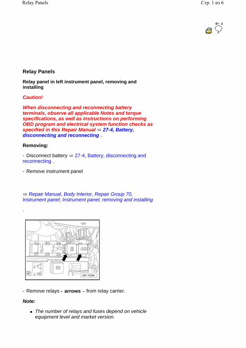
- Remove screws - arrows - and guide fuse panel - 1 - out toward inside, as far as wiring allows.
Installing:
Install in reverse order of removal, noting the following:
- Torque all fasteners according to value in table 97-7, Fuse panels, tightening torques .
Стр. 3 из 3Fuse Panels
Volkswagen Technical Site: http://volkswagen.msk.ru http://vwts.info http://vwts.ru огромный архив документации по автомобилям Volkswagen, Skoda, Seat, Audi
97 - 3
Relay Panels
Relay panel in left instrument panel, removing and installing
Caution!
When disconnecting and reconnecting battery terminals, observe all applicable Notes and torque specifications, as well as instructions on performing OBD program and electrical system function checks as specified in this Repair Manual 27-4, Battery, disconnecting and reconnecting .
Removing:
- Disconnect battery 27-4, Battery, disconnecting and reconnecting .
- Remove instrument panel
.
Repair Manual, Body Interior, Repair Group 70, Instrument panel; Instrument panel, removing and installing
- Remove relays - arrows - from relay carrier.
Note:
The number of relays and fuses depend on vehicle equipment level and market version.
Стр. 1 из 6Relay Panels
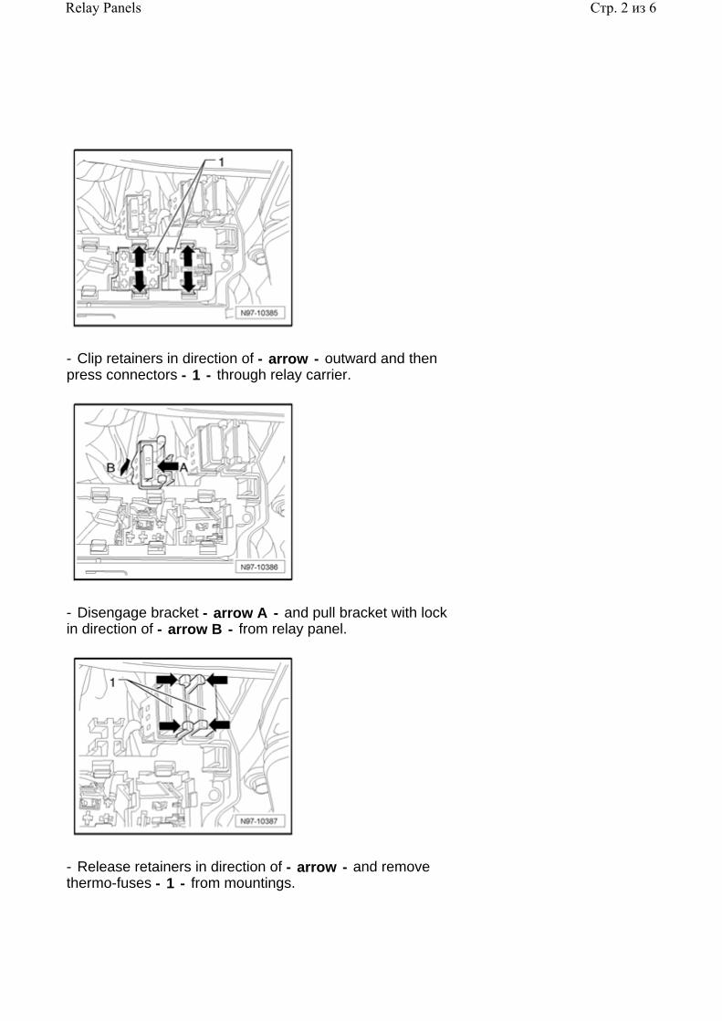
- Clip retainers in direction of - arrow - outward and then press connectors - 1 - through relay carrier.
- Disengage bracket - arrow A - and pull bracket with lock in direction of - arrow B - from relay panel.
- Release retainers in direction of - arrow - and remove thermo-fuses - 1 - from mountings.
Стр. 2 из 6Relay Panels
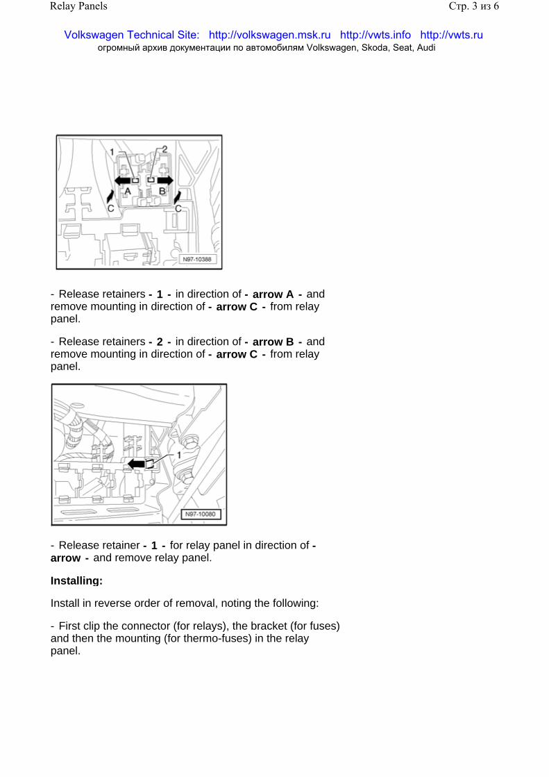
- Release retainers - 1 - in direction of - arrow A - and remove mounting in direction of - arrow C - from relay panel.
- Release retainers - 2 - in direction of - arrow B - and remove mounting in direction of - arrow C - from relay panel.
- Release retainer - 1 - for relay panel in direction of - arrow - and remove relay panel.
Installing:
Install in reverse order of removal, noting the following:
- First clip the connector (for relays), the bracket (for fuses) and then the mounting (for thermo-fuses) in the relay panel.
Стр. 3 из 6Relay Panels
Volkswagen Technical Site: http://volkswagen.msk.ru http://vwts.info http://vwts.ru огромный архив документации по автомобилям Volkswagen, Skoda, Seat, Audi
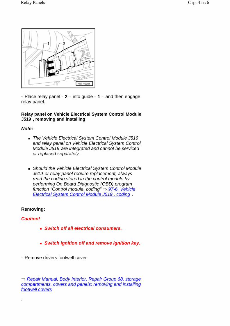
- Place relay panel - 2 - into guide - 1 - and then engage relay panel.
Relay panel on Vehicle Electrical System Control Module J519 , removing and installing
Note:
The Vehicle Electrical System Control Module J519 and relay panel on Vehicle Electrical System Control Module J519 are integrated and cannot be serviced or replaced separately.
Should the Vehicle Electrical System Control Module J519 or relay panel require replacement, always read the coding stored in the control module by performing On Board Diagnostic (OBD) program function "Control module, coding" 97-6, Vehicle Electrical System Control Module J519 , coding .
Removing:
Caution!
Switch off all electrical consumers.
Switch ignition off and remove ignition key.
- Remove drivers footwell cover
.
Repair Manual, Body Interior, Repair Group 68, storage compartments, covers and panels; removing and installing footwell covers
Стр. 4 из 6Relay Panels
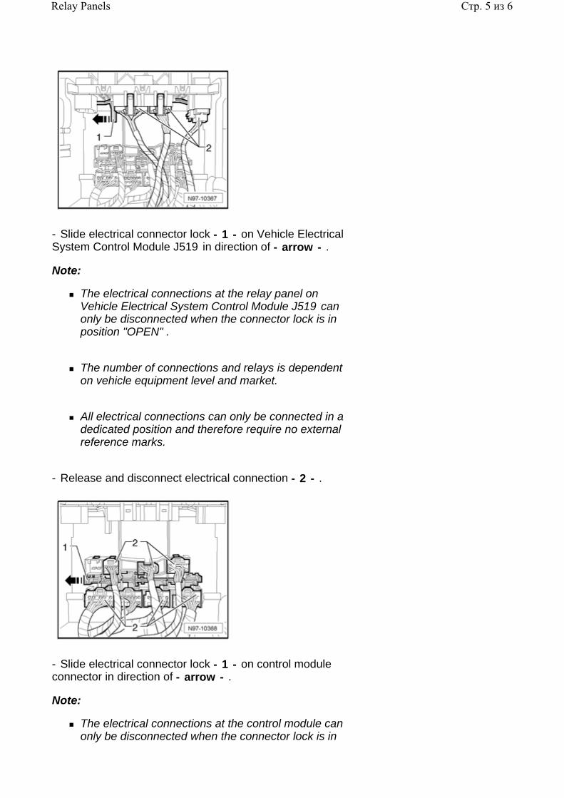
- Slide electrical connector lock - 1 - on Vehicle Electrical System Control Module J519 in direction of - arrow - .
Note:
The electrical connections at the relay panel on Vehicle Electrical System Control Module J519 can only be disconnected when the connector lock is in position "OPEN" .
The number of connections and relays is dependent on vehicle equipment level and market.
All electrical connections can only be connected in a dedicated position and therefore require no external reference marks.
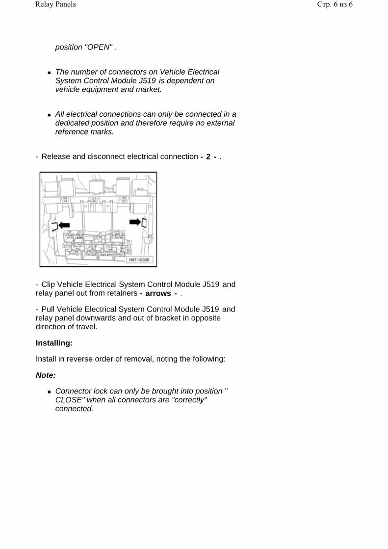
- Release and disconnect electrical connection - 2 - .
- Slide electrical connector lock - 1 - on control module connector in direction of - arrow - .
Note:
The electrical connections at the control module can only be disconnected when the connector lock is in
Стр. 5 из 6Relay Panels
position "OPEN" .
The number of connectors on Vehicle Electrical System Control Module J519 is dependent on vehicle equipment and market.
All electrical connections can only be connected in a dedicated position and therefore require no external reference marks.
- Release and disconnect electrical connection - 2 - .
- Clip Vehicle Electrical System Control Module J519 and relay panel out from retainers - arrows - .
- Pull Vehicle Electrical System Control Module J519 and relay panel downwards and out of bracket in opposite direction of travel.
Installing:
Install in reverse order of removal, noting the following:
Note:
Connector lock can only be brought into position " CLOSE" when all connectors are "correctly" connected.
Стр. 6 из 6Relay Panels
97 - 4
Electronics Boxes
Electronics Box in left engine compartment, removing and installing
Caution!
When disconnecting and reconnecting battery terminals, observe all applicable Notes and torque specifications, as well as instructions on performing OBD program and electrical system function checks as specified in this Repair Manual 27-4, Battery, disconnecting and reconnecting .
Removing:
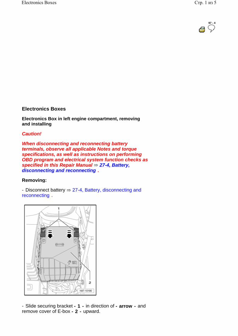
- Disconnect battery 27-4, Battery, disconnecting and reconnecting .
- Slide securing bracket - 1 - in direction of - arrow - and remove cover of E-box - 2 - upward.
Стр. 1 из 5Electronics Boxes
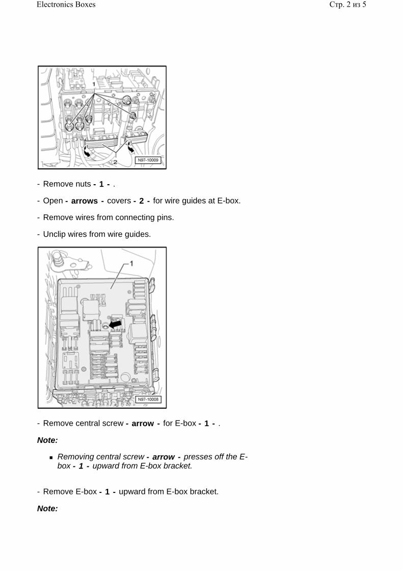
- Remove nuts - 1 - .
- Open - arrows - covers - 2 - for wire guides at E-box.
- Remove wires from connecting pins.
- Unclip wires from wire guides.
- Remove central screw - arrow - for E-box - 1 - .
Note:
Removing central screw - arrow - presses off the E-box - 1 - upward from E-box bracket.
- Remove E-box - 1 - upward from E-box bracket.
Note:
Стр. 2 из 5Electronics Boxes
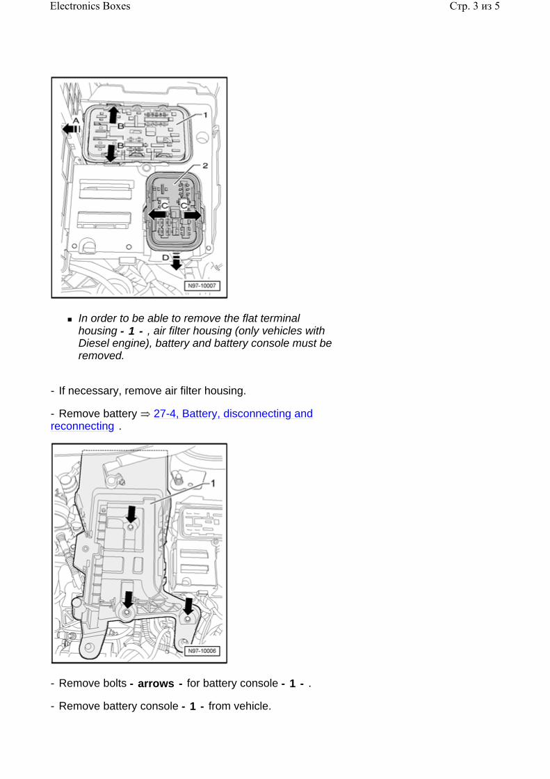
In order to be able to remove the flat terminal housing - 1 - , air filter housing (only vehicles with Diesel engine), battery and battery console must be removed.
- If necessary, remove air filter housing.
- Remove battery 27-4, Battery, disconnecting and reconnecting .
- Remove bolts - arrows - for battery console - 1 - .
- Remove battery console - 1 - from vehicle.
Стр. 3 из 5Electronics Boxes
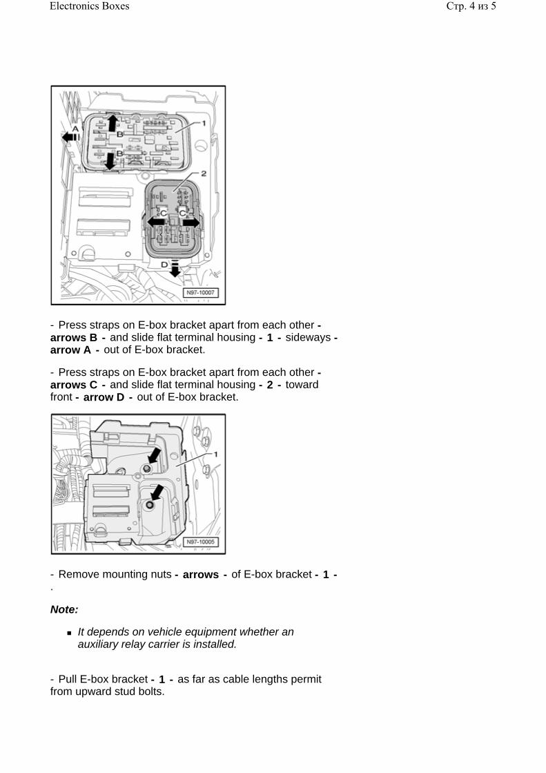
- Press straps on E-box bracket apart from each other - arrows B - and slide flat terminal housing - 1 - sideways - arrow A - out of E-box bracket.
- Press straps on E-box bracket apart from each other - arrows C - and slide flat terminal housing - 2 - toward front - arrow D - out of E-box bracket.
- Remove mounting nuts - arrows - of E-box bracket - 1 - .
Note:
It depends on vehicle equipment whether an auxiliary relay carrier is installed.
- Pull E-box bracket - 1 - as far as cable lengths permit from upward stud bolts.
Стр. 4 из 5Electronics Boxes
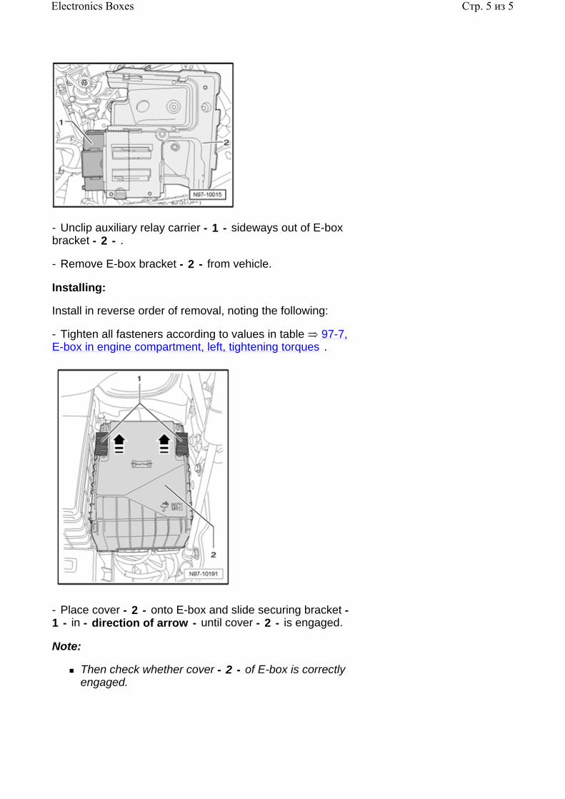
- Unclip auxiliary relay carrier - 1 - sideways out of E-box bracket - 2 - .
- Remove E-box bracket - 2 - from vehicle.
Installing:
Install in reverse order of removal, noting the following:
- Tighten all fasteners according to values in table 97-7, E-box in engine compartment, left, tightening torques .
- Place cover - 2 - onto E-box and slide securing bracket - 1 - in - direction of arrow - until cover - 2 - is engaged.
Note:
Then check whether cover - 2 - of E-box is correctly engaged.
Стр. 5 из 5Electronics Boxes
97 - 5
Power Supply Panel - 6-cylinder engines
A power supply panel is used in conjunction with the battery installed in the luggage compartment. The battery isolator is integrated with the power supply panel which is mounted above the battery in the left rear luggage compartment.
Note:
Additional information:
Electrical Wiring Diagrams, Troubleshooting and Component Locations binder
Power supply panel, removing and installing
The power supply panel is located above the battery in the left luggage compartment.
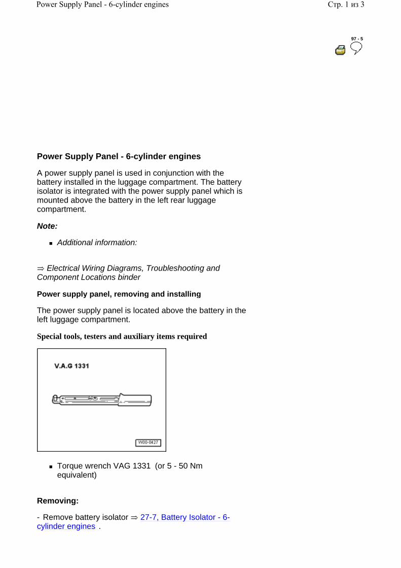
Special tools, testers and auxiliary items required
Torque wrench VAG 1331 (or 5 - 50 Nm equivalent)
Removing:
- Remove battery isolator 27-7, Battery Isolator - 6-cylinder engines .
Стр. 1 из 3Power Supply Panel - 6-cylinder engines
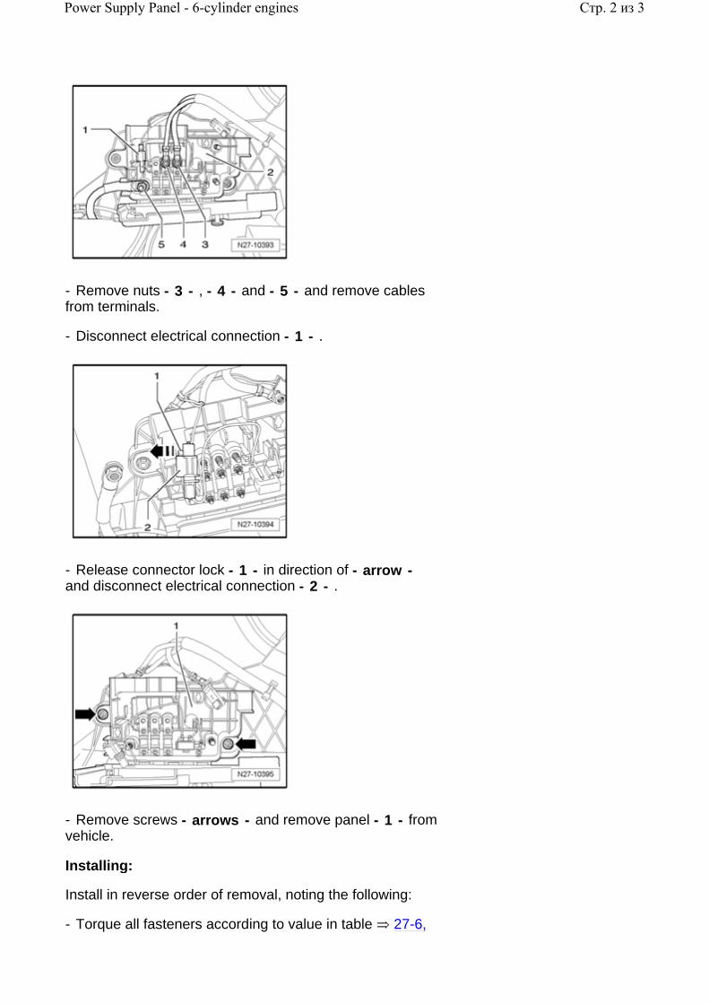
- Remove nuts - 3 - , - 4 - and - 5 - and remove cables from terminals.
- Disconnect electrical connection - 1 - .
- Release connector lock - 1 - in direction of - arrow - and disconnect electrical connection - 2 - .
- Remove screws - arrows - and remove panel - 1 - from vehicle.
Installing:
Install in reverse order of removal, noting the following:
- Torque all fasteners according to value in table 27-6,
Стр. 2 из 3Power Supply Panel - 6-cylinder engines

Tightening torques: Battery .
Стр. 3 из 3Power Supply Panel - 6-cylinder engines
97 - 6
Control Modules
Vehicle Electrical System Control Module J519 , servicing
Vehicle Electrical System Control Module J519 , general information
Vehicle Electrical System Control Module J519 performs the following tasks in the vehicle:
Electric load management
Exterior light control
Turn signal control
Wipers, rear window
Heated rear window
Interior light control
Shift-/selector gate illumination
Terminal control
Dimming, instrument illumination
Fuel Pump (FP) supply
Pre-energizing of generator
Horn
The following functions can be adapted:
Footwell illumination intensity, adapting 97-6, Footwell illumination brightness, adapting
Coming Home time, adapting 97-6, Coming Home
Стр. 1 из 37Control Modules
time, adapting
Leaving Home time, adapting 97-6, Leaving Home time, adapting
Headlamp cleaning system "on time" (spray duration), adapting 97-6, Headlamp washer system, adaptation
"Switch-off time" of rear window defogger and outside mirror heating function 97-6, Switch-off time of rear window defogger and outside mirror heating function
Note:
Adaptations listed above are dependent on vehicle equipment level and market version.
Note:
The Vehicle Electrical System Control Module J519 and relay panel on Vehicle Electrical System Control Module J519 are integrated and cannot be serviced or replaced separately.
Should the Vehicle Electrical System Control Module J519 or relay panel require replacement, always read the coding stored in the control module by performing On Board Diagnostic (OBD) program function "Control module, coding" 97-6, Vehicle Electrical System Control Module J519 , coding .
Note:
Additional information:
Self Study Program - Course Number 891503 "The 2006 Passat Introduction"
Self Study Program - Course Number 871503 "The 2006 Passat Electrical Systems Design and Function"
Electrical Wiring Diagrams, Troubleshooting and Component Locations binder
CAN-Bus wire repairs 97-8, Repairing CAN-Bus wires
Стр. 2 из 37Control Modules
On Board Diagnostic (OBD), function
Vehicle Electrical System Control Module J519 is equipped with On Board Diagnostics (OBD) which assists in troubleshooting.
For troubleshooting, use Vehicle Diagnostic, Testing and Information System VAS 5051/5052 in operating mode "Guided Fault Finding" .
Vehicle Electrical System Control Module J519 , removing and installing
Note:
The Vehicle Electrical System Control Module J519 and relay panel on Vehicle Electrical System Control Module J519 are integrated and cannot be serviced or replaced separately.
Should the Vehicle Electrical System Control Module J519 or relay panel require replacement, always read the coding stored in the control module by performing On Board Diagnostic (OBD) program function "Control module, coding" 97-6, Vehicle Electrical System Control Module J519 , coding .
Removing:
- Vehicle Electrical System Control Module J519 and relay panel on Vehicle Electrical System Control Module J519 , removing 97-3, Relay panel on Vehicle Electrical System Control Module J519 , removing and installing .
Installing:
- Vehicle Electrical System Control Module J519 and relay panel on Vehicle Electrical System Control Module J519 , installing 97-3, Relay panel on Vehicle Electrical System Control Module J519 , removing and installing .
Vehicle Electrical System Control Module J519 , coding
- Connect Vehicle Diagnostic, Testing and Information System VAS 5051/5052 97-1, VAS 5051 / 5052 .
- In Vehicle Diagnostic, Testing and Information System VAS 5051/5052 , select operating mode "Guided Fault Finding" .
- Using the "Go To" button, select "Functions/Component selection" and the following menu options in sequence:
Body
Стр. 3 из 37Control Modules
Electrical Equipment
01 - On Board Diagnostic (OBD) capable systems
Vehicle electrical system control module
Functions
Control module, coding
Vehicle Electrical System Control Module J519 , Output Diagnostic Test Mode (DTM)
Note:
Output DTM for the following components are dependent on vehicle equipment level and market version.
The following components and functions can be checked using Vehicle Electrical System Control Module J519 On Board Diagnostic (OBD) program function "Output Diagnostic Test Mode (DTM)" :
Left Parking Lamp M1 , Right Parking Lamp M3 , Left Taillamp M4 and Right Taillamp M2
Left Low Beam Headlamp M29 and Right Low Beam Headlamp M31
Left High Beam Headlamp M30 and Right High Beam Headlamp M32
Left Front Fog Lamp L22 and Right Front Fog Lamp L23
Right Back-Up Lamp M17
Left Brake Lamp M9 , Right Brake Lamp M10 and High-mount Brake Light M25
Left Rear Fog Lamp L46
Стр. 4 из 37Control Modules
License Plate Light X
Left Front Turn Signal Lamp M5 , Drivers Exterior Mirror Turn Signal Lamp L131 and Left Rear Turn Signal Lamp M6
Right Front Turn Signal Lamp M7 , Front Passengers Exterior Mirror Turn Signal Lamp L132 and Right Rear Turn Signal Lamp M8
Left Footwell Light W9 and Right Footwell Light W10
Interior lighting brightness
Illumination of all buttons, switches and instrument cluster
Power Supply Relay (terminal 30, B+) J317
LED heated rear window / heated rear window
LED heated outside mirror / heated outside mirror
Enabling - Sunroof
Enabling - Seat heating
Fuel Pump (FP) Relay J17
Headlamp Washer Relay J39 and Headlamp Washer Pump V11
Windshield wiper
Wiper module turning position
Windshield and Rear Window Washer Pump V59 , front
Стр. 5 из 37Control Modules
Windshield and Rear Window Washer Pump V59 , rear
Horn Relay J4 , High Tone Horn H2 and Low Tone Horn H7
- Connect Vehicle Diagnostic, Testing and Information System VAS 5051/5052 97-1, VAS 5051 / 5052 .
- In Vehicle Diagnostic, Testing and Information System VAS 5051/5052 , select operating mode "Guided Fault Finding" .
- Using the "Go To" button, select "Functions/Component selection" and the following menu options in sequence:
Body
Electrical Equipment
01 - On Board Diagnostic (OBD) capable systems
Vehicle electrical system control module
Functions
Output Diagnostic Test Mode (DTM) of Vehicle Electrical System Control Module
Automatic headlamps - high beam function, adapting
Note:
On models equipped with "Automatic Headlamps" , headlamps can be switched on and off automatically via a light sensor.
Additional information:
Owners Manual
High beam function (high beams switched on and off automatically) by performing OBD program, "adaptation" .
Стр. 6 из 37Control Modules
- Connect Vehicle Diagnostic, Testing and Information System VAS 5051/5052 97-1, VAS 5051 / 5052 .
- In Vehicle Diagnostic, Testing and Information System VAS 5051/5052 , select operating mode "Guided Fault Finding" .
- Using the "Go To" button, select "Functions/Component selection" and the following menu options in sequence:
Body
Electrical Equipment
01 - On Board Diagnostic (OBD) capable systems
Vehicle electrical system control module
Functions
High beams for assistance driving light, adapting
Automatic Headlamps delay, adapting
Note:
On models equipped with "Automatic Headlamps" , headlamps can be switched on and off automatically via a light sensor.
Additional information:
Owners Manual
Automatic headlamp on and off function can be adapted to a variable delay between 0 and 255 seconds.
- Connect Vehicle Diagnostic, Testing and Information System VAS 5051/5052 97-1, VAS 5051 / 5052 .
- In Vehicle Diagnostic, Testing and Information System VAS 5051/5052 , select operating mode "Guided Fault Finding" .
- Using the "Go To" button, select "Functions/Component selection" and the following menu options in sequence:
Body
Стр. 7 из 37Control Modules
Electrical Equipment
01 - On Board Diagnostic (OBD) capable systems
Vehicle electrical system control module
Functions
Delay assistance driving light, adapting
Footwell illumination brightness, adapting
Footwell illumination brightness is adjustable in variable levels.
- Connect Vehicle Diagnostic, Testing and Information System VAS 5051/5052 97-1, VAS 5051 / 5052 .
- In Vehicle Diagnostic, Testing and Information System VAS 5051/5052 , select operating mode "Guided Fault Finding" .
- Using the "Go To" button, select "Functions/Component selection" and the following menu options in sequence:
Body
Electrical Equipment
01 - On Board Diagnostic (OBD) capable systems
Vehicle electrical system control module
Functions
Footwell illumination brightness, adapting
Coming Home time, adapting
Coming Home function: Illumination time upon leaving vehicle.
The Coming Home illumination time can be adjusted
Стр. 8 из 37Control Modules
between 0 and 120 seconds.
- Connect Vehicle Diagnostic, Testing and Information System VAS 5051/5052 97-1, VAS 5051 / 5052 .
- In Vehicle Diagnostic, Testing and Information System VAS 5051/5052 , select operating mode "Guided Fault Finding" .
- Using the "Go To" button, select "Functions/Component selection" and the following menu options in sequence:
Body
Electrical Equipment
01 - On Board Diagnostic (OBD) capable systems
Vehicle electrical system control module
Functions
Coming Home time, adapting
Leaving Home time, adapting
Leaving Home function: Illumination time upon entering vehicle.
The Leaving Home illumination time can be adjusted between 0 and 120 seconds.
- Connect Vehicle Diagnostic, Testing and Information System VAS 5051/5052 97-1, VAS 5051 / 5052 .
- In Vehicle Diagnostic, Testing and Information System VAS 5051/5052 , select operating mode "Guided Fault Finding" .
- Using the "Go To" button, select "Functions/Component selection" and the following menu options in sequence:
Body
Electrical Equipment
01 - On Board Diagnostic (OBD) capable systems
Стр. 9 из 37Control Modules
Vehicle electrical system control module
Functions
Leaving Home time, adapting
Headlamp washer system, adaptation
The "active time" of headlamp cleaning system can be adjusted between 0 seconds and 12.75 seconds.
- Connect Vehicle Diagnostic, Testing and Information System VAS 5051/5052 97-1, VAS 5051 / 5052 .
- In Vehicle Diagnostic, Testing and Information System VAS 5051/5052 , select operating mode "Guided Fault Finding" .
- Using the "Go To" button, select "Functions/Component selection" and the following menu options in sequence:
Body
Electrical Equipment
01 - On Board Diagnostic (OBD) capable systems
Vehicle electrical system control module
Functions
Headlamp washer system, adaptation
Switch-off time of rear window defogger and outside mirror heating function
Heated outside mirror and heated rear window function duration can adjusted between 1 minute and 255 minutes.
Note:
This adaptation is only possible on vehicles with basic equipment.
- Connect Vehicle Diagnostic, Testing and Information System VAS 5051/5052 97-1, VAS 5051 / 5052 .
Стр. 10 из 37Control Modules
- In Vehicle Diagnostic, Testing and Information System VAS 5051/5052 , select operating mode "Guided Fault Finding" .
- Using the "Go To" button, select "Functions/Component selection" and the following menu options in sequence:
Body
Electrical Equipment
01 - On Board Diagnostic (OBD) capable systems
Vehicle electrical system control module
Functions
Shut-off time of heated rear window/outside mirror, adapting
Data Bus On Board Diagnostic Interface J533 , servicing
Data Bus On Board Diagnostic Interface J533 , general information
The Data Bus On Board Diagnostic Interface J533 (Gateway) exists as a separate control module. It has the following tasks in the vehicle:
Perform data exchange between CAN-Bus systems "Powertrain CAN-Bus" , "Convenience CAN-Bus" and "Infotainment CAN-Bus"
Transfers diagnostic data of CAN-Bus systems onto K-wire and vice-versa, allowing the data from the VAS 5051/5052 testers to be utilized
Note:
Should the Data Bus On Board Diagnostic Interface J533 require replacement, always read the coding stored in the control module by performing On Board Diagnostic (OBD) program function "Data Bus On Board Diagnostic Interface, replacing" 97-6, Data Bus On Board Diagnostic Interface J533 , replacing .
Стр. 11 из 37Control Modules
The sleep mode status of individual CAN-Bus systems (Powertrain, Comfort and Infotainment) can be monitored
97-6, CAN-Bus activity, checking .
In addition, the communication between the Data Bus On Board Diagnostic Interface J533 and CAN-Bus systems can be checked 97-6, CAN-Bus systems, checking .
Note:
Additional information:
Self Study Program - Course Number 891503 "The 2006 Passat Introduction"
Self Study Program - Course Number 871503 "The 2006 Passat Electrical Systems Design and Function"
Electrical Wiring Diagrams, Troubleshooting and Component Locations binder
CAN-Bus wire repairs 97-8, Repairing CAN-Bus wires
On Board Diagnostic (OBD), function
Data Bus On Board Diagnostic Interface J533 is equipped with On Board Diagnostics (OBD) which assists troubleshooting.
For troubleshooting, use Vehicle Diagnostic, Testing and Information System VAS 5051/5052 in operating mode "Guided Fault Finding" .
Data Bus On Board Diagnostic Interface J533 , replacing
- Connect Vehicle Diagnostic, Testing and Information System VAS 5051/5052 97-1, VAS 5051 / 5052 .
- In Vehicle Diagnostic, Testing and Information System VAS 5051/5052 , select operating mode "Guided Fault Finding" .
- Using the "Go To" button, select "Functions/Component selection" and the following menu options in sequence:
Body
Electrical Equipment
01 - On Board Diagnostic (OBD) capable systems
Data Bus On Board Diagnostic Interface
Стр. 12 из 37Control Modules
Functions of Data Bus On Board Diagnostic Interface
Replace Data Bus On Board Diagnostic Interface
- Data Bus On Board Diagnostic Interface J533 , removing and installing 97-6, Data Bus On Board Diagnostic Interface J533 , removing and installing .
Data Bus On Board Diagnostic Interface J533 , removing and installing
Removing:
Note:
Should the Data Bus On Board Diagnostic Interface J533 require replacement, the work procedure to read out the coding stored in the module must always be performed 97-6, Data Bus On Board Diagnostic Interface J533 , replacing .
Caution!
Switch off all electrical consumers.
Switch ignition off and remove ignition key.
- Remove drivers footwell cover
.
Repair Manual, Body Interior, Repair Group 68, storage compartments, covers and panels; removing and installing footwell covers
Стр. 13 из 37Control Modules
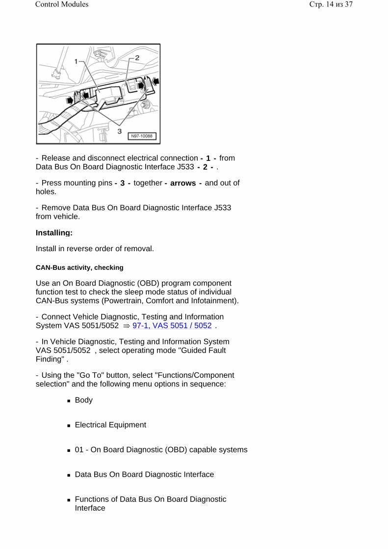
- Release and disconnect electrical connection - 1 - from Data Bus On Board Diagnostic Interface J533 - 2 - .
- Press mounting pins - 3 - together - arrows - and out of holes.
- Remove Data Bus On Board Diagnostic Interface J533 from vehicle.
Installing:
Install in reverse order of removal.
CAN-Bus activity, checking
Use an On Board Diagnostic (OBD) program component function test to check the sleep mode status of individual CAN-Bus systems (Powertrain, Comfort and Infotainment).
- Connect Vehicle Diagnostic, Testing and Information System VAS 5051/5052 97-1, VAS 5051 / 5052 .
- In Vehicle Diagnostic, Testing and Information System VAS 5051/5052 , select operating mode "Guided Fault Finding" .
- Using the "Go To" button, select "Functions/Component selection" and the following menu options in sequence:
Body
Electrical Equipment
01 - On Board Diagnostic (OBD) capable systems
Data Bus On Board Diagnostic Interface
Functions of Data Bus On Board Diagnostic Interface
Стр. 14 из 37Control Modules
CAN-Bus activity, checking
CAN-Bus systems, checking
Use an On Board Diagnostic (OBD) program component function test to check the communication between the Data Bus On Board Diagnostic Interface and CAN-Bus systems.
- Connect Vehicle Diagnostic, Testing and Information System VAS 5051/5052 97-1, VAS 5051 / 5052 .
- In Vehicle Diagnostic, Testing and Information System VAS 5051/5052 , select operating mode "Guided Fault Finding" .
- Using the "Go To" button, select "Functions/Component selection" and the following menu options in sequence:
Body
Electrical Equipment
01 - On Board Diagnostic (OBD) capable systems
Data Bus On Board Diagnostic Interface
Functions of Data Bus On Board Diagnostic Interface
CAN-Bus systems, checking
Comfort System Central Control Module J393 , servicing
Comfort System Central Control Module J393 , general information
Depending on vehicle equipment level and market version, the following control module functions are integrated with Comfort System Central Control Module J393 :
Anti-Theft Immobilizer Control Module J362
Tire Pressure Monitoring Control Module J502
Стр. 15 из 37Control Modules
Function:
Depending on vehicle equipment level and market version, the Comfort System Central Control Module J393 performs the following tasks in the vehicle:
Central locking system control
Rear door control module control
Rear lid release control
Fuel filler lid release control
Anti-theft alarm system control. Additional information 96-11, Anti-Theft Alarm System
Anti-theft immobilizer system control. Additional information 96-10, Anti-theft Immobilizer
Tire pressure monitoring system control. Additional information
Repair Manual, Suspension, Wheels, Steering, Repair Group 44,
Note:
Should the Comfort System Central Control Module J393 require replacement, always read the coding stored in the control module by performing On Board Diagnostic (OBD) program function "Comfort System Central Control Module, replacing/coding" 97-6, Comfort System Central Control Module J393 , replacing/coding .
After replacing Comfort System Central Control Module J393 , other functions of Comfort System Central Control Module such as "Anti-theft Immobilizer" , "Anti-theft Alarm System" , "tire pressure monitoring" and central locking system key must also be adapted, depending on vehicle equipment.
Стр. 16 из 37Control Modules
In this case, start by adapting the Anti-theft Immobilizer 96-10, Adapting Anti-Theft Immobilizer Control Module J362 and then the other equipment-dependent functions of Comfort System Central Control Module J393 in any order.
Connect Vehicle Diagnostic, Testing and Information System VAS 5051, select operating mode "Guided Fault Finding" , select "Go To" , select "Function/Component Selection" and the following menu options: "Body" , "Body Collision Repair" , "01-Systems capable of self-diagnosis" , "Convenience system" and "Functions - Central control module for convenience system" , to adapt the following where applicable:
Note:
The following adaptations depend on vehicle equipment and market version. Some adaptations are not possible on USA/CDN models.
"Factory Mode" , deactivating
"Individual door opening" , adapting
"Automatic locking" , adapting
"Automatic unlocking when key is removed" , adapting
"Acknowledgement - Unlock via Access and Start Authorization" , adapting
"Acknowledgement - Unlock via radio-frequency remote control" , adapting
"Acknowledgement - Unlock via key switch" , adapting
"Acknowledgement - Lock via Access and Start Authorization" , adapting
"Acknowledgement - Lock via radio-frequency remote control" , adapting
Стр. 17 из 37Control Modules
"Acknowledgement - Lock via key switch" , adapting
"Acknowledgement - Anti-theft alarm system armed" , adapting
"Intelligent Alarm Horn, market version" , adapting
"Tilt sensor sensitivity" , adapting
"Interior monitoring sensitivity" , adapting
"Battery monitoring (Sounder)" , adapting
"Comfort operation via radio-frequency remote" , adapting
"Alarm delay when drivers door opened" , adapting
Note:
Additional information:
Owners Manual
Self Study Program - Course Number 891503 "The 2006 Passat Introduction"
Self Study Program - Course Number 871503 "The 2006 Passat Electrical Systems Design and Function"
Electrical Wiring Diagrams, Troubleshooting and Component Locations binder
CAN-Bus wire repairs 97-8, Repairing CAN-Bus wires
On Board Diagnostic (OBD), function
The Comfort System Central Control Module J393 has On Board Diagnostic (OBD) capabilities which aids in troubleshooting.
For troubleshooting, use Vehicle Diagnostic, Testing and Information System VAS 5051/5052 in operating mode "Guided Fault Finding" .
Comfort System Central Control Module J393 , removing and installing
Стр. 18 из 37Control Modules
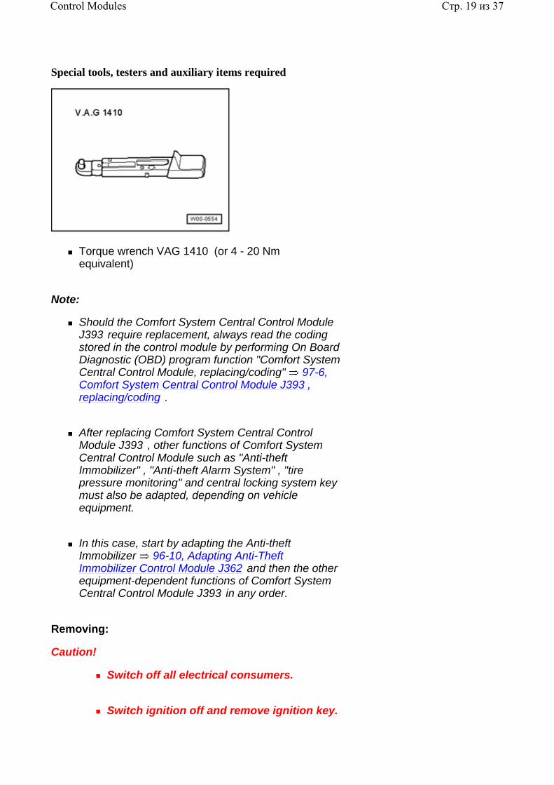
Special tools, testers and auxiliary items required
Torque wrench VAG 1410 (or 4 - 20 Nm equivalent)
Note:
Should the Comfort System Central Control Module J393 require replacement, always read the coding stored in the control module by performing On Board Diagnostic (OBD) program function "Comfort System Central Control Module, replacing/coding" 97-6, Comfort System Central Control Module J393 , replacing/coding .
After replacing Comfort System Central Control Module J393 , other functions of Comfort System Central Control Module such as "Anti-theft Immobilizer" , "Anti-theft Alarm System" , "tire pressure monitoring" and central locking system key must also be adapted, depending on vehicle equipment.
In this case, start by adapting the Anti-theft Immobilizer 96-10, Adapting Anti-Theft Immobilizer Control Module J362 and then the other equipment-dependent functions of Comfort System Central Control Module J393 in any order.
Removing:
Caution!
Switch off all electrical consumers.
Switch ignition off and remove ignition key.
Стр. 19 из 37Control Modules
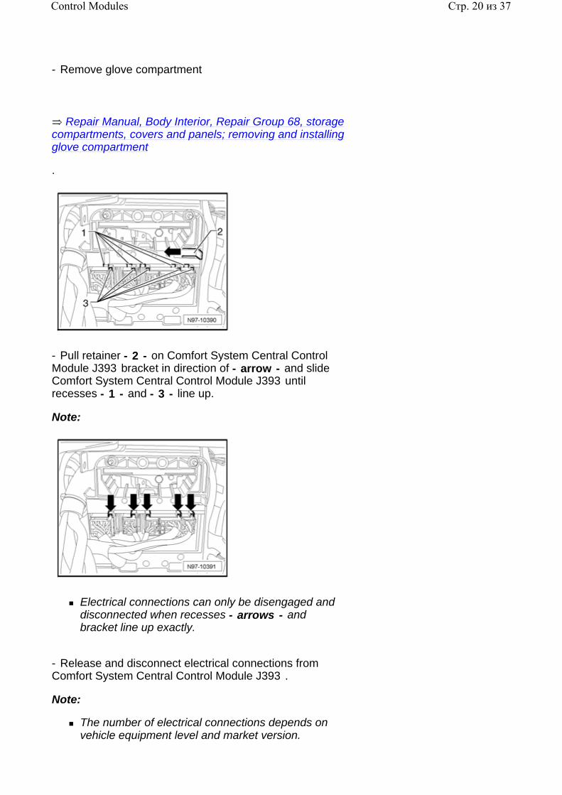
- Remove glove compartment
.
Repair Manual, Body Interior, Repair Group 68, storage compartments, covers and panels; removing and installing glove compartment
- Pull retainer - 2 - on Comfort System Central Control Module J393 bracket in direction of - arrow - and slide Comfort System Central Control Module J393 until recesses - 1 - and - 3 - line up.
Note:
Electrical connections can only be disengaged and disconnected when recesses - arrows - and bracket line up exactly.
- Release and disconnect electrical connections from Comfort System Central Control Module J393 .
Note:
The number of electrical connections depends on vehicle equipment level and market version.
Стр. 20 из 37Control Modules
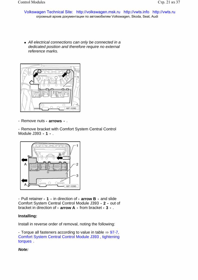
All electrical connections can only be connected in a dedicated position and therefore require no external reference marks.
- Remove nuts - arrows - .
- Remove bracket with Comfort System Central Control Module J393 - 1 - .
- Pull retainer - 1 - in direction of - arrow B - and slide Comfort System Central Control Module J393 - 2 - out of bracket in direction of - arrow A - from bracket - 3 - .
Installing:
Install in reverse order of removal, noting the following:
- Torque all fasteners according to value in table 97-7, Comfort System Central Control Module J393 , tightening torques .
Note:
Стр. 21 из 37Control Modules
Volkswagen Technical Site: http://volkswagen.msk.ru http://vwts.info http://vwts.ru огромный архив документации по автомобилям Volkswagen, Skoda, Seat, Audi
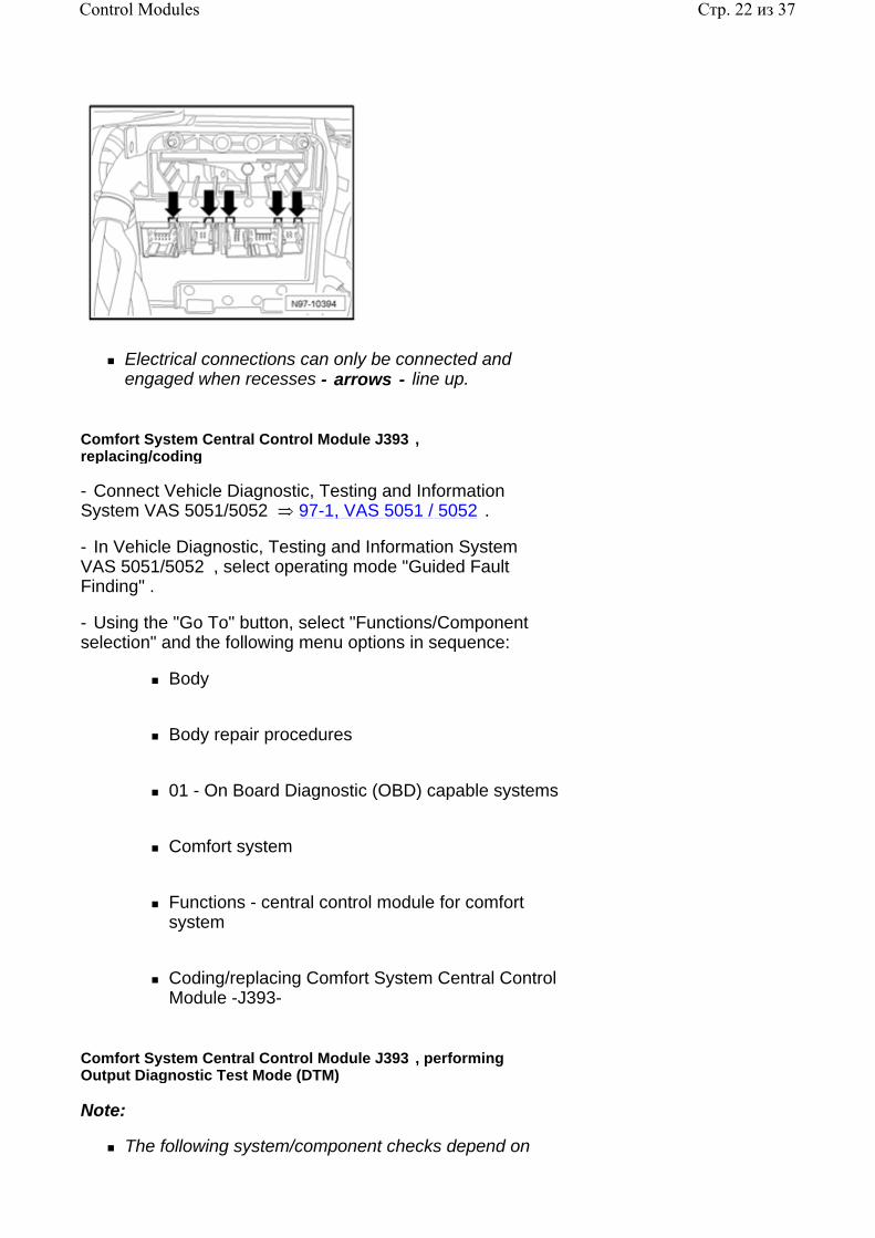
Electrical connections can only be connected and engaged when recesses - arrows - line up.
Comfort System Central Control Module J393 , replacing/coding
- Connect Vehicle Diagnostic, Testing and Information System VAS 5051/5052 97-1, VAS 5051 / 5052 .
- In Vehicle Diagnostic, Testing and Information System VAS 5051/5052 , select operating mode "Guided Fault Finding" .
- Using the "Go To" button, select "Functions/Component selection" and the following menu options in sequence:
Body
Body repair procedures
01 - On Board Diagnostic (OBD) capable systems
Comfort system
Functions - central control module for comfort system
Coding/replacing Comfort System Central Control Module -J393-
Comfort System Central Control Module J393 , performing Output Diagnostic Test Mode (DTM)
Note:
The following system/component checks depend on
Стр. 22 из 37Control Modules
vehicle equipment level and market version.
The following components and functions can be checked using Comfort System Central Control Module J393 On Board Diagnostic (OBD) program function "Output Diagnostic Test Mode (DTM)" :
Left Rear Entry Light W33
Left Rear Central Locking Lock Unit F222 (left rear door central locking is activated)
Right Rear Entry Light W34
Right Rear Central Locking Lock Unit F223 (right rear door central locking is activated)
Fuel filler lid release control (fuel filler lid is opened)
Rear lid release control (rear lid is opened)
Vehicle Inclination Sensor Indicator Lamp K188 (LED) in Interior Monitoring Deactivation Switch E267
Interior Monitoring -Off- Indicator Lamp K162 (LED) in Deactivate Vehicle Inclination Sensor Button E360
Alarm Horn H12
- Connect Vehicle Diagnostic, Testing and Information System VAS 5051/5052 97-1, VAS 5051 / 5052 .
- In Vehicle Diagnostic, Testing and Information System VAS 5051/5052 , select operating mode "Guided Fault Finding" .
- Using the "Go To" button, select "Functions/Component selection" and the following menu options in sequence:
Body
Body repair procedures
Стр. 23 из 37Control Modules
01 - On Board Diagnostic (OBD) capable systems
Comfort system
Functions - central control module for comfort system
Comfort System Central Control Module -J393-, Output Diagnostic Test Mode (DTM)
Anti-theft alarm system - alarm sources, checking
Alarm sources for anti-theft alarm system can be identified, for example: Vehicle Inclination Sensor G384 (or others).
- Connect Vehicle Diagnostic, Testing and Information System VAS 5051/5052 97-1, VAS 5051 / 5052 .
- In Vehicle Diagnostic, Testing and Information System VAS 5051/5052 , select operating mode "Guided Fault Finding" .
- Using the "Go To" button, select "Functions/Component selection" and the following menu options in sequence:
Body
Body repair procedures
01 - On Board Diagnostic (OBD) capable systems
Comfort system
Functions - central control module for comfort system
Comfort System Central Control Module -J393-, checking alarm sources of anti-theft warning system
Alarm Horn - alarm sources, checking
Alarm sources for Alarm Horn can be identified, for example: vehicle battery monitoring or alarm source triggered via comfort control module.
Стр. 24 из 37Control Modules
- Connect Vehicle Diagnostic, Testing and Information System VAS 5051/5052 97-1, VAS 5051 / 5052 .
- In Vehicle Diagnostic, Testing and Information System VAS 5051/5052 , select operating mode "Guided Fault Finding" .
- Using the "Go To" button, select "Functions/Component selection" and the following menu options in sequence:
Body
Body repair procedures
01 - On Board Diagnostic (OBD) capable systems
Comfort system
Functions - central control module for comfort system
J393 - Alarm Horn - alarm sources, checking
Drivers Door Control Module J386 , servicing
Drivers Door Control Module J386 , general information
Note:
The Drivers Door Control Module J386 and Drivers Window Regulator Motor V147 are integrated and cannot be serviced or replaced separately.
In the event that the Drivers Door Control Module J386 or Drivers Window Regulator Motor V147 require replacement, always perform On Board Diagnostic (OBD) program function "Drivers Door Control Module, coding" 97-6, Drivers Door Control Module J386 , coding .
Note:
Additional information:
Owners Manual
Стр. 25 из 37Control Modules
Self Study Program - Course Number 891503 "The 2006 Passat Introduction"
Self Study Program - Course Number 871503 "The 2006 Passat Electrical Systems Design and Function"
Electrical Wiring Diagrams, Troubleshooting and Component Locations binder
CAN-Bus wire repairs 97-8, Repairing CAN-Bus wires
Drivers Door Control Module J386 , removing and installing
Drivers Door Control Module J386 , removing and installing
.
Repair Manual, Body Exterior, Repair Group 64, Glass, Window regulators; front door windows, window regulator motor, removing and installing
Note:
In the event that the Drivers Door Control Module J386 or Drivers Window Regulator Motor V147 require replacement, always perform On Board Diagnostic (OBD) program function "Drivers Door Control Module, coding" 97-6, Drivers Door Control Module J386 , coding .
Drivers Door Control Module J386 , coding
- Connect Vehicle Diagnostic, Testing and Information System VAS 5051/5052 97-1, VAS 5051 / 5052 .
- In Vehicle Diagnostic, Testing and Information System VAS 5051/5052 , select operating mode "Guided Fault Finding" .
- Using the "Go To" button, select "Functions/Component selection" and the following menu options in sequence:
Body
Body repair procedures
01 - On Board Diagnostic (OBD) capable systems
Стр. 26 из 37Control Modules
Door electronics, drivers side
Drivers door control module, functions
J386 - Drivers Door Control Module, coding
Drivers Door Control Module J386 , performing Output Diagnostic Test Mode (DTM)
Note:
The following system/component checks depend on vehicle equipment level and market version.
The following components and functions can be checked using the door control module On Board Diagnostic (OBD) program function "Output Diagnostic Test Mode (DTM)" :
Drivers switches illumination control
Drivers side central locking control (activation)
Drivers exterior mirror control (mirror heating and fold-in function)
Turn signals in drivers exterior mirror ( Drivers Exterior Mirror Turn Signal Lamp L131 ) control
Entry lamp in drivers exterior mirror ( Drivers Entry Lamp (in outside mirror) W52 ) control
Drivers window regulator control (lowering)
Drivers window regulator control (raising)
- Connect Vehicle Diagnostic, Testing and Information System VAS 5051/5052 97-1, VAS 5051 / 5052 .
- In Vehicle Diagnostic, Testing and Information System VAS 5051/5052 , select operating mode "Guided Fault Finding" .
- Using the "Go To" button, select "Functions/Component selection" and the following menu options in sequence:
Стр. 27 из 37Control Modules
Body
Body repair procedures
01 - On Board Diagnostic (OBD) capable systems
Door electronics, drivers side
Drivers door control module, functions
J386 - Drivers Door Control Module, Output Diagnostic Test Mode (DTM)
Front Passengers Door Control Module J387
Front Passengers Door Control Module J387 , general information
Note:
The Front Passengers Door Control Module J387 and Front Passengers Window Regulator Motor V148 are integrated and cannot be serviced or replaced separately.
In the event that the Front Passengers Door Control Module J387 or Front Passengers Window Regulator Motor V148 require replacement, always perform On Board Diagnostic (OBD) program function "Front Passengers Door Control Module, coding" 97-6, Front Passengers Door Control Module J387 , coding .
Note:
Additional information:
Owners Manual
Self Study Program - Course Number 891503 "The 2006 Passat Introduction"
Self Study Program - Course Number 871503 "The 2006 Passat Electrical Systems Design and Function"
Electrical Wiring Diagrams, Troubleshooting and
Стр. 28 из 37Control Modules
Component Locations binder
CAN-Bus wire repairs 97-8, Repairing CAN-Bus wires
Front Passengers Door Control Module J387 , removing and installing
Front Passengers Door Control Module J387 , removing and installing
.
Repair Manual, Body Exterior, Repair Group 64, Glass, Window regulators; front door windows, window regulator motor, removing and installing
Note:
In the event that the Front Passengers Door Control Module J387 or Front Passengers Window Regulator Motor V148 require replacement, always perform On Board Diagnostic (OBD) program function "Front Passengers Door Control Module, coding" 97-6, Front Passengers Door Control Module J387 , coding .
Front Passengers Door Control Module J387 , coding
- Connect Vehicle Diagnostic, Testing and Information System VAS 5051/5052 97-1, VAS 5051 / 5052 .
- In Vehicle Diagnostic, Testing and Information System VAS 5051/5052 , select operating mode "Guided Fault Finding" .
- Using the "Go To" button, select "Functions/Component selection" and the following menu options in sequence:
Body
Body repair procedures
01 - On Board Diagnostic (OBD) capable systems
Door electronics, front passengers side
Front passengers door control module, functions
Стр. 29 из 37Control Modules

Front Passengers Door Control Module J387 , coding
Front Passengers Door Control Module J387 , performing Output Diagnostic Test Mode (DTM)
Note:
The following system/component checks depend on vehicle equipment level and market version.
The following components and functions can be checked using the door control module On Board Diagnostic (OBD) program function "Output Diagnostic Test Mode (DTM)" :
Front passengers switches illumination control
Front passengers side central locking control (activation)
Front passengers exterior mirror control (mirror heating and fold-in function)
Turn signals in front passengers exterior mirror ( Front Passengers Exterior Mirror Turn Signal Lamp L132 ) control
Entry lamp in front passengers exterior mirror ( Front Passengers Entry Lamp (in outside mirror) W53 ) control
Front passengers window regulator control (lowering)
Front passengers window regulator control (raising)
- Connect Vehicle Diagnostic, Testing and Information System VAS 5051/5052 97-1, VAS 5051 / 5052 .
- In Vehicle Diagnostic, Testing and Information System VAS 5051/5052 , select operating mode "Guided Fault Finding" .
- Using the "Go To" button, select "Functions/Component selection" and the following menu options in sequence:
Body
Стр. 30 из 37Control Modules
Body repair procedures
01 - On Board Diagnostic (OBD) capable systems
Door electronics, front passengers side
Front passengers door control module, functions
J387 - Front Passengers Door Control Module, Output Diagnostic Test Mode (DTM)
Left Rear Door Control Module J388
Left Rear Door Control Module J388 , general information
Note:
The Left Rear Door Control Module J388 and Left Rear Window Regulator Motor V26 are integrated and cannot be serviced or replaced separately.
In the event that the Left Rear Door Control Module J388 or Left Rear Window Regulator Motor V26 require replacement, always perform On Board Diagnostic (OBD) program function "Left Rear Door Control Module, coding" 97-6, Left Rear Door Control Module J388 , coding .
Note:
Additional information:
Owners Manual
Self Study Program - Course Number 891503 "The 2006 Passat Introduction"
Self Study Program - Course Number 871503 "The 2006 Passat Electrical Systems Design and Function"
Electrical Wiring Diagrams, Troubleshooting and Component Locations binder
CAN-Bus wire repairs 97-8, Repairing CAN-Bus wires
Стр. 31 из 37Control Modules
Left Rear Door Control Module J388 , removing and installing
Left Rear Door Control Module J388 , removing and installing
.
Repair Manual, Body Exterior, Repair Group 64, Glass, Window regulators; rear door windows, window regulator motor, removing and installing
Note:
In the event that the Left Rear Door Control Module J388 or Left Rear Window Regulator Motor V26 require replacement, always perform On Board Diagnostic (OBD) program function "Left Rear Door Control Module, coding" 97-6, Left Rear Door Control Module J388 , coding .
Left Rear Door Control Module J388 , coding
- Connect Vehicle Diagnostic, Testing and Information System VAS 5051/5052 97-1, VAS 5051 / 5052 .
- In Vehicle Diagnostic, Testing and Information System VAS 5051/5052 , select operating mode "Guided Fault Finding" .
- Using the "Go To" button, select "Functions/Component selection" and the following menu options in sequence:
Body
Body repair procedures
01 - On Board Diagnostic (OBD) capable systems
Left rear door electronics
Left Rear Door Control Module functions
J388 - Left Rear Door Control Module, coding
Left Rear Door Control Module J388 , performing Output Diagnostic Test Mode (DTM)
Стр. 32 из 37Control Modules
Note:
The following system/component checks depend on vehicle equipment level and market version.
The following components and functions can be checked using the door control module On Board Diagnostic (OBD) program function "Output Diagnostic Test Mode (DTM)" :
Left rear door switches illumination control
Left rear window regulator control (lowering)
Left rear window regulator control (raising)
- Connect Vehicle Diagnostic, Testing and Information System VAS 5051/5052 97-1, VAS 5051 / 5052 .
- In Vehicle Diagnostic, Testing and Information System VAS 5051/5052 , select operating mode "Guided Fault Finding" .
- Using the "Go To" button, select "Functions/Component selection" and the following menu options in sequence:
Body
Body repair procedures
01 - On Board Diagnostic (OBD) capable systems
Left rear door electronics
Left Rear Door Control Module functions
J388 - Left Rear Door Control Module, Output Diagnostic Test Mode (DTM)
Right Rear Door Control Module J389
Right Rear Door Control Module J389 , general information
Note:
The Right Rear Door Control Module J389 and Right Rear Window Regulator Motor V27 are integrated
Стр. 33 из 37Control Modules
and cannot be serviced or replaced separately.
In the event that the Right Rear Door Control Module J389 or Right Rear Window Regulator Motor V27 require replacement, always perform On Board Diagnostic (OBD) program function "Right Rear Door Control Module, coding" 97-6, Right Rear Door Control Module J389 , coding .
Note:
Additional information:
Owners Manual
Self Study Program - Course Number 891503 "The 2006 Passat Introduction"
Self Study Program - Course Number 871503 "The 2006 Passat Electrical Systems Design and Function"
Electrical Wiring Diagrams, Troubleshooting and Component Locations binder
CAN-Bus wire repairs 97-8, Repairing CAN-Bus wires
Right Rear Door Control Module J389 , removing and installing
Right Rear Door Control Module J389 , removing and installing
.
Repair Manual, Body Exterior, Repair Group 64, Glass, Window regulators; rear door windows, window regulator motor, removing and installing
Note:
In the event that the Right Rear Door Control Module J389 or Right Rear Window Regulator Motor V27 require replacement, always perform On Board Diagnostic (OBD) program function "Right Rear Door Control Module, coding" 97-6, Right Rear Door Control Module J389 , coding .
Right Rear Door Control Module J389 , coding
- Connect Vehicle Diagnostic, Testing and Information
Стр. 34 из 37Control Modules
System VAS 5051/5052 97-1, VAS 5051 / 5052 .
- In Vehicle Diagnostic, Testing and Information System VAS 5051/5052 , select operating mode "Guided Fault Finding" .
- Using the "Go To" button, select "Functions/Component selection" and the following menu options in sequence:
Body
Body repair procedures
01 - On Board Diagnostic (OBD) capable systems
Right rear door electronics
Right Rear Door Control Module, functions
J389 - Right Rear Door Control Module, coding
Right Rear Door Control Module J389 , performing Output Diagnostic Test Mode (DTM)
Note:
The following system/component checks depend on vehicle equipment level and market version.
The following components and functions can be checked using the door control module On Board Diagnostic (OBD) program function "Output Diagnostic Test Mode (DTM)" :
Right rear door switches illumination control
Right rear window regulator control (lowering)
Right rear window regulator control (raising)
- Connect Vehicle Diagnostic, Testing and Information System VAS 5051/5052 97-1, VAS 5051 / 5052 .
- In Vehicle Diagnostic, Testing and Information System VAS 5051/5052 , select operating mode "Guided Fault Finding" .
Стр. 35 из 37Control Modules
- Using the "Go To" button, select "Functions/Component selection" and the following menu options in sequence:
Body
Body repair procedures
01 - On Board Diagnostic (OBD) capable systems
Right rear door electronics
Right Rear Door Control Module, functions
J389 - Right Rear Door Control Module, Output Diagnostic Test Mode (DTM)
Electronic Steering Column Lock Control Module J764
The Steering Column Lock Actuator N360 is integrated in the Electronic Steering Column Lock Control Module J764 . Steering Column Lock Actuator N360 cannot be replaced separately.
Note:
Electronic Steering Column Lock Control Module J764 is secured to steering column with shear bolts and must only be replaced as part of the complete steering column.
All information on further procedures can be obtained via the Vehicle Diagnosis, Testing and Information System VAS 5051A .
If Electronic Steering Column Lock Control Module J764 is to be replaced, the work procedure "adapt Electronic Steering Column Lock Control Module" must always be performed beforehand 96-10, Adapting Electronic Steering Column Lock Control Module J764 .
Electronic Steering Column Lock Control Module J764 , removing and installing
Removing and installing Electronic Steering Column Lock Control Module J764 96-10, Electronic Steering Column
Стр. 36 из 37Control Modules
Lock Control Module J764 , removing and installing .
Adapting Electronic Steering Column Lock Control Module J764
Adapting Electronic Steering Column Lock Control Module J764 96-10, Adapting Electronic Steering Column Lock Control Module J764 .
Checking Electronic Steering Column Lock Control Module J764
Checking Electronic Steering Column Lock Control Module J764 96-10, Checking Electronic Steering Column Lock Control Module J764 .
Стр. 37 из 37Control Modules
97 - 7
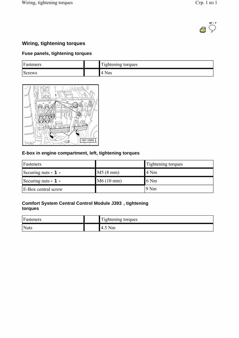
Wiring, tightening torques
Fuse panels, tightening torques
Fasteners Tightening torques
Screws 4 Nm
E-box in engine compartment, left, tightening torques
Fasteners Tightening torques
Securing nuts - 1 - M5 (8 mm) 4 Nm
Securing nuts - 1 - M6 (10 mm) 6 Nm
E-Box central screw 9 Nm
Comfort System Central Control Module J393 , tightening torques
Fasteners Tightening torques
Nuts 4.5 Nm
Стр. 1 из 1Wiring, tightening torques
97 - 8
Wiring harness and connectors, repairing
Safety measures
Caution!
Before beginning repairs on the electrical system:
Where applicable, obtain the anti-theft radio security code .
Switch off all electrical consumers.
Switch ignition off and remove ignition key.
Disconnect negative ( - ) battery terminal.
When disconnecting and reconnecting battery terminals, observe all applicable Notes and torque specifications, as well as instructions on performing OBD program and electrical system function checks as specified in this Repair Manual. 27-4, Battery, disconnecting and reconnecting . Not adhering to proper disconnection sequence will result in the deactivation of Main Battery Switch -E74- and subsequent damage to electrical system components.
Caution!
Airbag and safety belt tensioner harness and connector repairs must only be performed using VAS 1978 Wiring Harness Repair Kit VAS 1978 Instruction Manual .
Airbag and safety belt tensioner harness and connector repairs must only be performed using applicable wires, connectors and terminals Parts Catalog .
Wiring harness repair kit
Wiring Harness Repair Kit VAS1978
Стр. 1 из 45Wiring harness and connectors, repairing
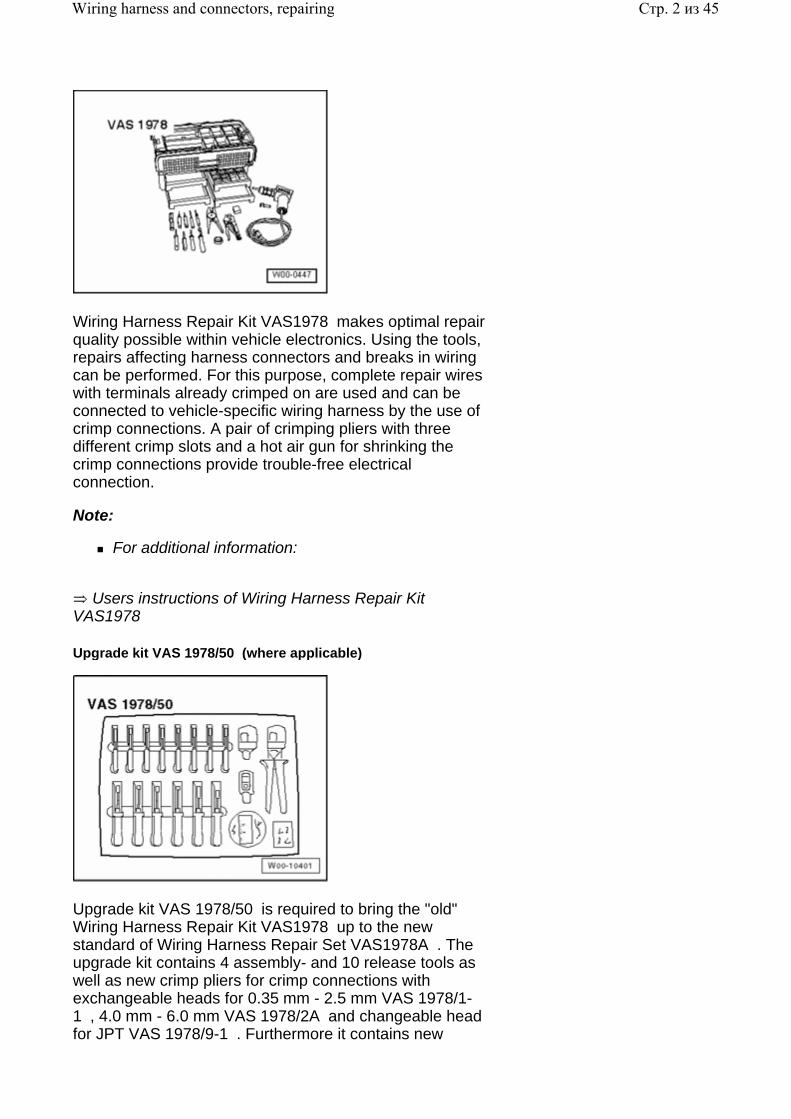
Wiring Harness Repair Kit VAS1978 makes optimal repair quality possible within vehicle electronics. Using the tools, repairs affecting harness connectors and breaks in wiring can be performed. For this purpose, complete repair wires with terminals already crimped on are used and can be connected to vehicle-specific wiring harness by the use of crimp connections. A pair of crimping pliers with three different crimp slots and a hot air gun for shrinking the crimp connections provide trouble-free electrical connection.
Note:
For additional information:
Users instructions of Wiring Harness Repair Kit VAS1978
Upgrade kit VAS 1978/50 (where applicable)
Upgrade kit VAS 1978/50 is required to bring the "old" Wiring Harness Repair Kit VAS1978 up to the new standard of Wiring Harness Repair Set VAS1978A . The upgrade kit contains 4 assembly- and 10 release tools as well as new crimp pliers for crimp connections with exchangeable heads for 0.35 mm - 2.5 mm VAS 1978/1-1 , 4.0 mm - 6.0 mm VAS 1978/2A and changeable head for JPT VAS 1978/9-1 . Furthermore it contains new
Стр. 2 из 45Wiring harness and connectors, repairing
stickers, a new set of user instructions, crimp connections for 0.35mm 2 -wire cross sections and a roll of black felt adhesive tape.
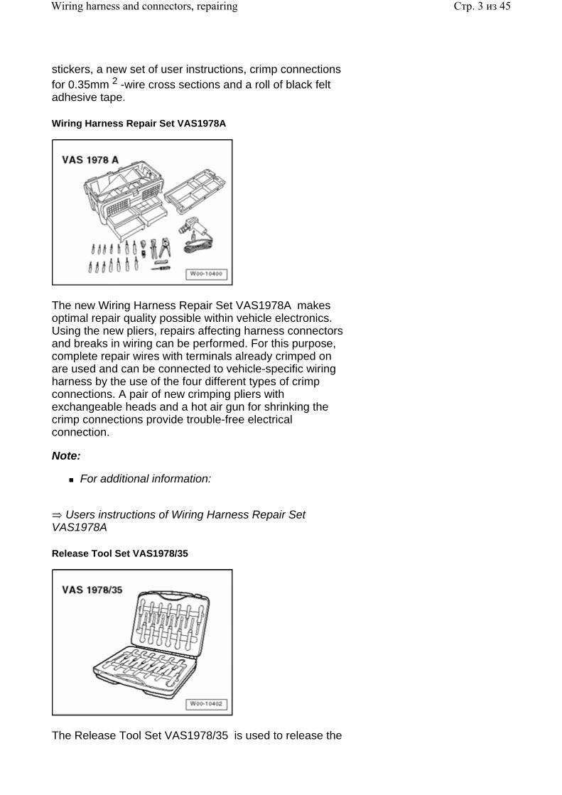
Wiring Harness Repair Set VAS1978A
The new Wiring Harness Repair Set VAS1978A makes optimal repair quality possible within vehicle electronics. Using the new pliers, repairs affecting harness connectors and breaks in wiring can be performed. For this purpose, complete repair wires with terminals already crimped on are used and can be connected to vehicle-specific wiring harness by the use of the four different types of crimp connections. A pair of new crimping pliers with exchangeable heads and a hot air gun for shrinking the crimp connections provide trouble-free electrical connection.
Note:
For additional information:
Users instructions of Wiring Harness Repair Set VAS1978A
Release Tool Set VAS1978/35
The Release Tool Set VAS1978/35 is used to release the
Стр. 3 из 45Wiring harness and connectors, repairing
various primary and secondary locking mechanisms on VW-group vehicles. The set consists of 26 different tools which can be used to professionally release or assemble e.g. round connector systems, flat terminals with one or two locks as well as single wire seals.
The application of the correct release tools to the respective locks can be found in the table in users instructions for Release Tool Set VAS1978/35 .
Tool descriptions
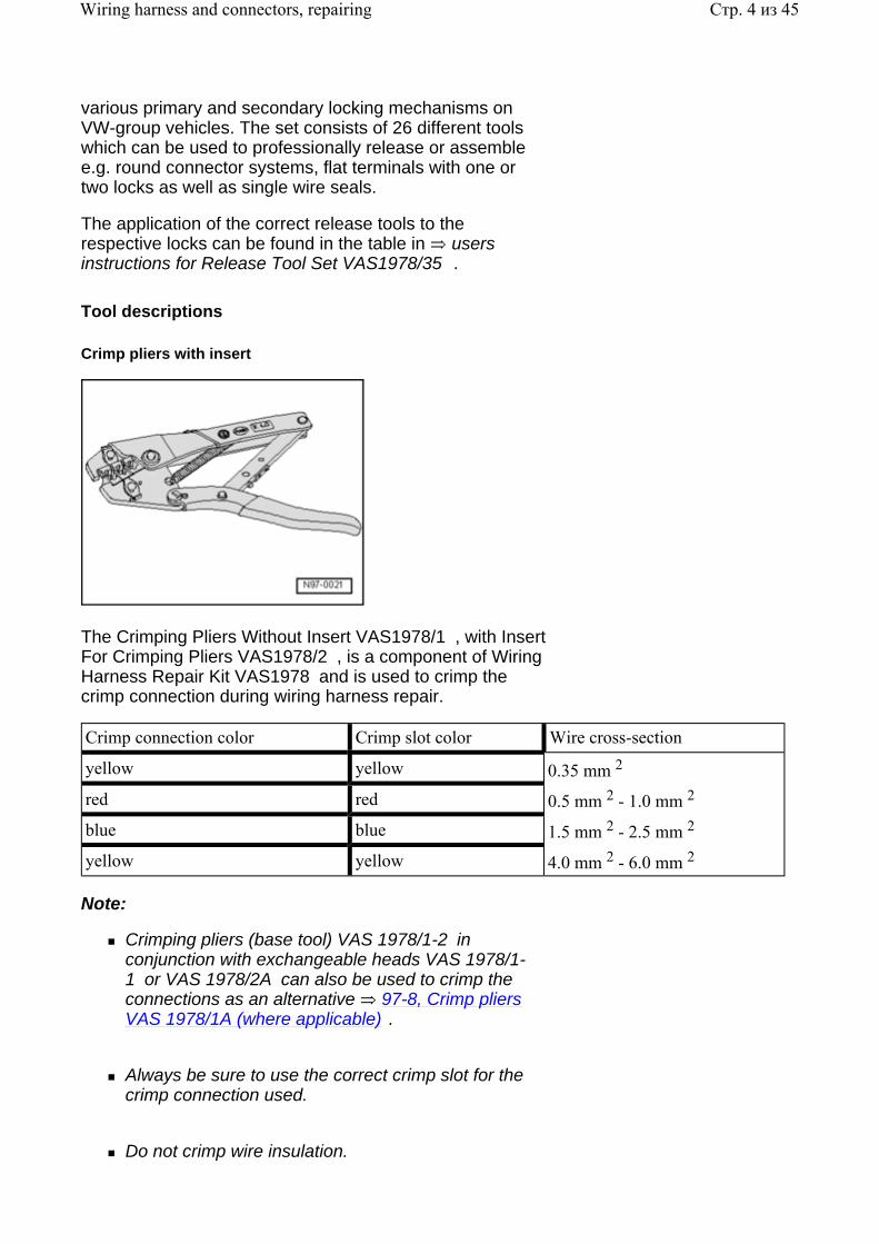
Crimp pliers with insert
The Crimping Pliers Without Insert VAS1978/1 , with Insert For Crimping Pliers VAS1978/2 , is a component of Wiring Harness Repair Kit VAS1978 and is used to crimp the crimp connection during wiring harness repair.
Crimp connection color Crimp slot color Wire cross-section
yellow yellow 0.35 mm 2 red red 0.5 mm 2 - 1.0 mm 2 blue blue 1.5 mm 2 - 2.5 mm 2 yellow yellow 4.0 mm 2 - 6.0 mm 2
Note:
Crimping pliers (base tool) VAS 1978/1-2 in conjunction with exchangeable heads VAS 1978/1-1 or VAS 1978/2A can also be used to crimp the connections as an alternative 97-8, Crimp pliers VAS 1978/1A (where applicable) .
Always be sure to use the correct crimp slot for the crimp connection used.
Do not crimp wire insulation.
Стр. 4 из 45Wiring harness and connectors, repairing
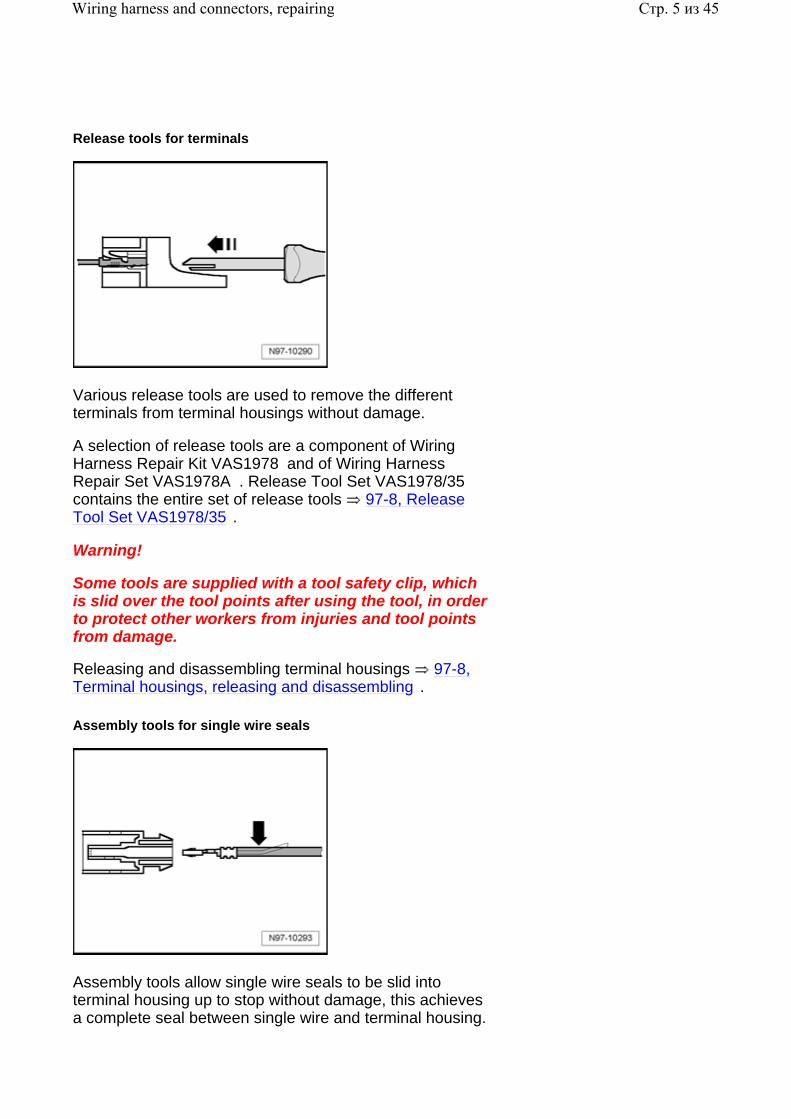
Release tools for terminals
Various release tools are used to remove the different terminals from terminal housings without damage.
A selection of release tools are a component of Wiring Harness Repair Kit VAS1978 and of Wiring Harness Repair Set VAS1978A . Release Tool Set VAS1978/35 contains the entire set of release tools 97-8, Release Tool Set VAS1978/35 .
Warning!
Some tools are supplied with a tool safety clip, which is slid over the tool points after using the tool, in order to protect other workers from injuries and tool points from damage.
Releasing and disassembling terminal housings 97-8, Terminal housings, releasing and disassembling .
Assembly tools for single wire seals
Assembly tools allow single wire seals to be slid into terminal housing up to stop without damage, this achieves a complete seal between single wire and terminal housing.
Стр. 5 из 45Wiring harness and connectors, repairing
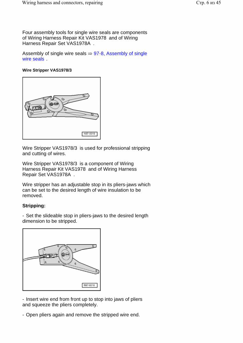
Four assembly tools for single wire seals are components of Wiring Harness Repair Kit VAS1978 and of Wiring Harness Repair Set VAS1978A .
Assembly of single wire seals 97-8, Assembly of single wire seals .
Wire Stripper VAS1978/3
Wire Stripper VAS1978/3 is used for professional stripping and cutting of wires.
Wire Stripper VAS1978/3 is a component of Wiring Harness Repair Kit VAS1978 and of Wiring Harness Repair Set VAS1978A .
Wire stripper has an adjustable stop in its pliers-jaws which can be set to the desired length of wire insulation to be removed.
Stripping:
- Set the slideable stop in pliers-jaws to the desired length dimension to be stripped.
- Insert wire end from front up to stop into jaws of pliers and squeeze the pliers completely.
- Open pliers again and remove the stripped wire end.
Стр. 6 из 45Wiring harness and connectors, repairing
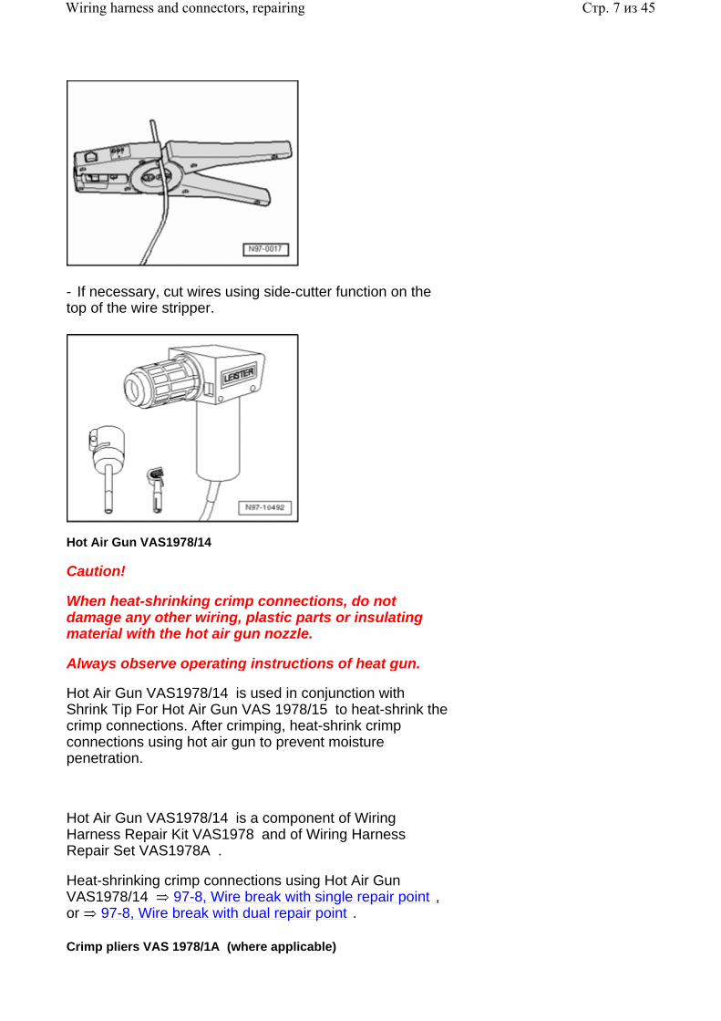
- If necessary, cut wires using side-cutter function on the top of the wire stripper.
Hot Air Gun VAS1978/14
Caution!
When heat-shrinking crimp connections, do not damage any other wiring, plastic parts or insulating material with the hot air gun nozzle.
Always observe operating instructions of heat gun.
Hot Air Gun VAS1978/14 is used in conjunction with Shrink Tip For Hot Air Gun VAS 1978/15 to heat-shrink the crimp connections. After crimping, heat-shrink crimp connections using hot air gun to prevent moisture penetration.
Hot Air Gun VAS1978/14 is a component of Wiring Harness Repair Kit VAS1978 and of Wiring Harness Repair Set VAS1978A .
Heat-shrinking crimp connections using Hot Air Gun VAS1978/14 97-8, Wire break with single repair point , or 97-8, Wire break with dual repair point .
Crimp pliers VAS 1978/1A (where applicable)
Стр. 7 из 45Wiring harness and connectors, repairing
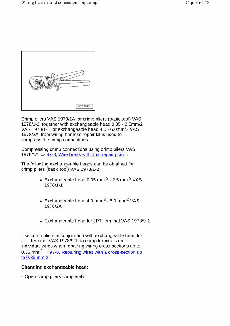
Crimp pliers VAS 1978/1A or crimp pliers (basic tool) VAS 1978/1-2 together with exchangeable head 0.35 - 2.5mm/2 VAS 1978/1-1 or exchangeable head 4.0 - 6.0mm/2 VAS 1978/2A from wiring harness repair kit is used to compress the crimp connections.
Compressing crimp connections using crimp pliers VAS 1978/1A 97-8, Wire break with dual repair point .
The following exchangeable heads can be obtained for crimp pliers (basic tool) VAS 1978/1-2 :
Exchangeable head 0.35 mm 2 - 2.5 mm 2 VAS 1978/1-1
Exchangeable head 4.0 mm 2 - 6.0 mm 2 VAS 1978/2A
Exchangeable head for JPT-terminal VAS 1978/9-1
Use crimp pliers in conjunction with exchangeable head for JPT-terminal VAS 1978/9-1 to crimp terminals on to individual wires when repairing wiring cross-sections up to 0.35 mm 2 97-8, Repairing wires with a cross-section up to 0.35 mm 2 .
Changing exchangeable head:
- Open crimp pliers completely.
Стр. 8 из 45Wiring harness and connectors, repairing
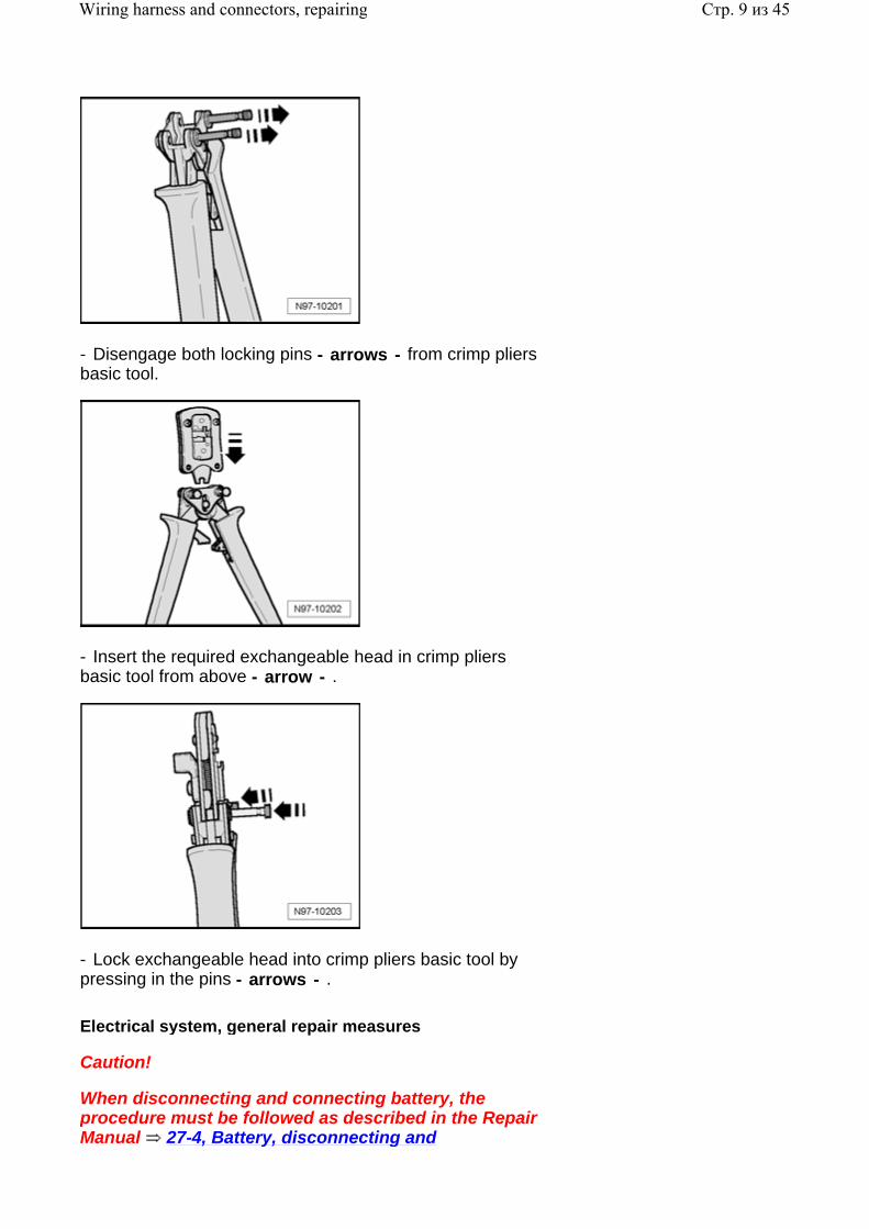
- Disengage both locking pins - arrows - from crimp pliers basic tool.
- Insert the required exchangeable head in crimp pliers basic tool from above - arrow - .
- Lock exchangeable head into crimp pliers basic tool by pressing in the pins - arrows - .
Electrical system, general repair measures
Caution!
When disconnecting and connecting battery, the procedure must be followed as described in the Repair Manual 27-4, Battery, disconnecting and
Стр. 9 из 45Wiring harness and connectors, repairing
reconnecting .
Always refer to and heed CAUTION! and WARNING! texts associated with repair and/or removal and installation information in the Repair Manual.
Only the yellow repair cables and insulation tape supplied with VAS 1978 are to be used for wiring/connector repairs. The use of yellow repair wires and yellow insulation tape identifies that a repair has taken place VAS 1978 Instruction Manual .
Before beginning wiring and connector repairs, determine and rectify the cause of damage, Eg.: pinched between metal parts, malfunctioning electrical consumers, corrosion due to water ingress etc.
Avoid loosening or removing any individual ground connections (potential for corrosion).
When repairs are completed, always perform a functional check of the component or system. Where applicable, check and erase Diagnostic Trouble Codes (DTCs) and set basic settings where applicable according to Repair Manual and/or VAS 5051/5052.
Warning!
Some tools are supplied with a tool safety clip, which is slid over the tool points after using the tool, in order to protect other workers from injuries and tool points from damage.
Observe the current information in the corresponding Repair Manual for all repairs.
Observe country-specific laws.
Before working on electrical system, disconnect battery Ground (GND) strap.
By disconnecting battery Ground (GND) strap (current disruption), safe work on the electrical system is guaranteed. It is necessary to disconnect battery positive wire only when removing the battery.
Further information, e.g. installing and removing individual components, can be found in the appropriate Repair Manual.
Стр. 10 из 45Wiring harness and connectors, repairing
For repairs to vehicle electrical system, soldering is not permitted.
Only perform wiring harness and connector repairs to vehicle electrical system using Wiring Harness Repair Kit VAS1978 or Wiring Harness Repair Set VAS1978A .
Wiring harness repairs may only be carried out using yellow wires.
Wiring harness repairs may not be performed again in the wrapping of the vehicle-specific wiring harness and are to be marked with yellow adhesive tape.
These yellow wires and every location on wiring harness wrapped in yellow insulating tape indicates a previous repair.
Crimp connections must never be repaired. If necessary, lay a wire parallel to the faulty wire.
After crimping, heat-shrink crimp connections using hot air gun to prevent moisture penetration.
Always observe also the supplementary notes for repairing wiring harnesses on airbag- and seat belt tensioner systems, fiber optic cables, CAN-Bus wires, antenna wires and wire cross-sections up to 0.35 mm 2 97-8, Notes for wiring harness repairs .
Perform a function test after every repair. If necessary, check DTC memory, erase and/or bring systems into basic setting.
If possible, do not loosen Ground (GND) straps from body (danger of corrosion).
Wiring harnesses, repairing
Note:
Observe general notes for repairs on the vehicle
Стр. 11 из 45Wiring harness and connectors, repairing
electrical system 97-8, Electrical system, general repair measures .
Not all the wire cross-sections installed in the vehicle are contained in the Wiring Harness Repair Kit VAS1978 or Wiring Harness Repair Set VAS1978A . If the wire cross-section required is not present, use the next greater cross-section.
Caution!
Note specific CAN-Bus wiring repair measures 97-8, Repairing CAN-Bus wires .
Note specific primary and secondary terminal and connector repair measures 97-8, Terminal housings, releasing and disassembling
Soldering is not permitted!
Do not repair welded connections in the wiring harness. Fabricate and connect an appropriate overlay harness instead.
Wiring harness and connector repairs must only be performed using VAS 1978 Wiring Harness Repair Kit VAS 1978 Instruction Manual .
Only the yellow repair cables and insulation tape supplied with VAS 1978 are to be used for wiring/connector repairs. The use of yellow repair wires and yellow insulation tape identifies that a repair has taken place.
All shielded wiring (Eg.: knock sensors, antenna etc.) are Not to be repaired! Replace complete wiring harnesses as necessary.
Notes for wiring harness repairs
Note:
Wiring harness and connector repairs to vehicle electrical system must only be performed using Wiring Harness Repair Kit VAS1978 or Wiring Harness Repair Set VAS1978A .
Стр. 12 из 45Wiring harness and connectors, repairing
For repairs to vehicle electrical system, soldering is not permitted.
Wiring harness repairs may only be performed using yellow wires.
Wiring harness repairs may not be performed again in the wrapping of the vehicle-specific wiring harness and are to be marked with yellow adhesive tape.
These yellow wires and every location on wiring harness wrapped in yellow insulating tape indicates a previous repair.
Crimp connections must never be repaired. If necessary, lay a wire parallel to the faulty wire.
After crimping, heat-shrink crimp connections using hot air gun to prevent moisture penetration.
Shielded wires must not be repaired. Replace completely if damaged.
Heat-resistant wires have been installed in the vehicle at various locations, mainly in the engine compartment. Heat-resistant wires can be recognized by their somewhat duller and softer insulation. Only heat-resistant wires may be used to repair these wires.
Always observe also the supplementary notes for repairing wiring harnesses on airbag- and seat belt tensioner systems, fiber optic cables, CAN-Bus wires, antenna wires and wires with cross-sections up to 0.35 mm 2 .
Supplemental information for repairing airbag- and seat belt tensioner wires 97-8, Repairing airbag- and seat belt tensioner wires
Supplemental information for repairing fiber optic cables 97-8, Fiber-optic cables
Supplemental information for repairing CAN-Bus wires
Стр. 13 из 45Wiring harness and connectors, repairing
97-8, Repairing CAN-Bus wires
Supplemental information for replacing antenna wires 97-8, Replacing antenna wires
Supplemental information for repairing wires with a cross-section up to 0.35 mm 2 97-8, Repairing wires with a cross-section up to 0.35 mm 2
Repairing airbag- and seat belt tensioner wires
In addition to the general repairs on wiring harnesses, observe the following methods and instructions for repairs on airbag- and seat belt tensioner wires:
Warning!
Airbag and seat belt tensioner can fail.
Faulty repairs performed on airbag and seat belt tensioner system can lead to malfunction in passenger protection.
When performing repairs on airbag and seat belt tensioner wiring harness, use only terminals, connectors and wires designated for it Parts Catalog (ETKA) .
Note:
Only use Wiring Harness Repair Kit VAS1978 or Wiring Harness Repair Set VAS1978A to repair wires of airbag- and seat belt tensioner wiring harness.
Pay attention to stickers designating high voltage components. When performing repairs, residual voltage must be discharged
.
Repair Manual, Body Interior, Repair Group 69, Passenger protection
Стр. 14 из 45Wiring harness and connectors, repairing
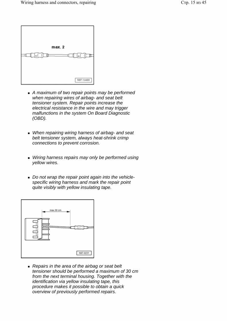
A maximum of two repair points may be performed when repairing wires of airbag- and seat belt tensioner system. Repair points increase the electrical resistance in the wire and may trigger malfunctions in the system On Board Diagnostic (OBD).
When repairing wiring harness of airbag- and seat belt tensioner system, always heat-shrink crimp connections to prevent corrosion.
Wiring harness repairs may only be performed using yellow wires.
Do not wrap the repair point again into the vehicle-specific wiring harness and mark the repair point quite visibly with yellow insulating tape.
Repairs in the area of the airbag or seat belt tensioner should be performed a maximum of 30 cm from the next terminal housing. Together with the identification via yellow insulating tape, this procedure makes it possible to obtain a quick overview of previously performed repairs.
Стр. 15 из 45Wiring harness and connectors, repairing
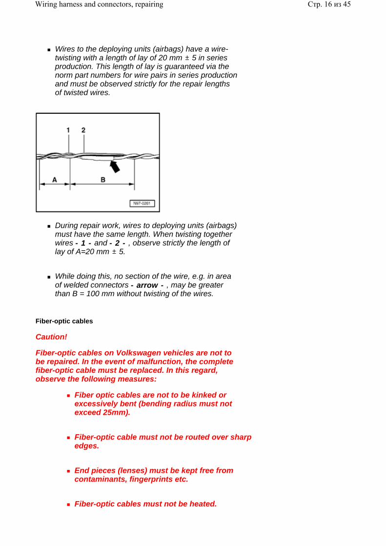
Wires to the deploying units (airbags) have a wire-twisting with a length of lay of 20 mm 5 in series production. This length of lay is guaranteed via the norm part numbers for wire pairs in series production and must be observed strictly for the repair lengths of twisted wires.
During repair work, wires to deploying units (airbags) must have the same length. When twisting together wires - 1 - and - 2 - , observe strictly the length of lay of A=20 mm 5.
While doing this, no section of the wire, e.g. in area of welded connectors - arrow - , may be greater than B = 100 mm without twisting of the wires.
Fiber-optic cables
Caution!
Fiber-optic cables on Volkswagen vehicles are not to be repaired. In the event of malfunction, the complete fiber-optic cable must be replaced. In this regard, observe the following measures:
Fiber optic cables are not to be kinked or excessively bent (bending radius must not exceed 25mm).
Fiber-optic cable must not be routed over sharp edges.
End pieces (lenses) must be kept free from contaminants, fingerprints etc.
Fiber-optic cables must not be heated.
Стр. 16 из 45Wiring harness and connectors, repairing
A pair of fiber-optic cables must not be twisted together, nor should a single fiber-optic cable be twisted together with a copper wire conductor.
Repairing CAN-Bus wires
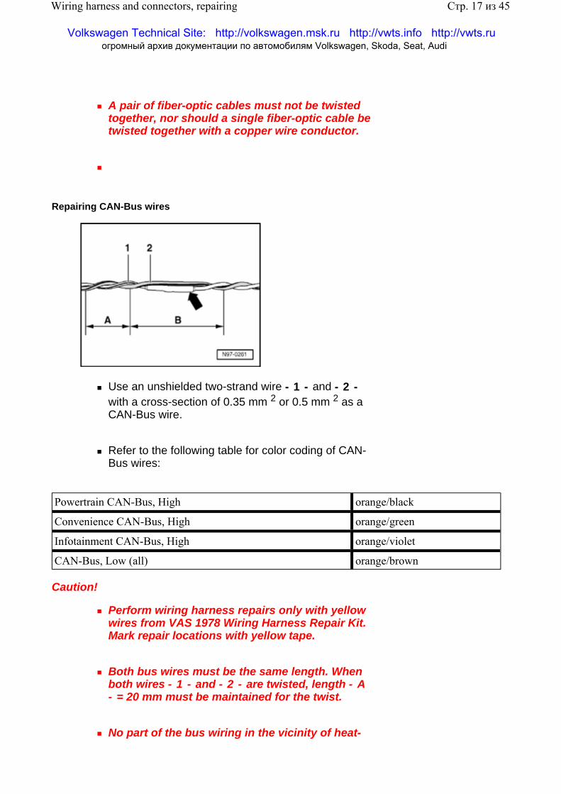
Use an unshielded two-strand wire - 1 - and - 2 - with a cross-section of 0.35 mm 2 or 0.5 mm 2 as a CAN-Bus wire.
Refer to the following table for color coding of CAN-Bus wires:
Powertrain CAN-Bus, High orange/black
Convenience CAN-Bus, High orange/green
Infotainment CAN-Bus, High orange/violet
CAN-Bus, Low (all) orange/brown
Caution!
Perform wiring harness repairs only with yellow wires from VAS 1978 Wiring Harness Repair Kit. Mark repair locations with yellow tape.
Both bus wires must be the same length. When both wires - 1 - and - 2 - are twisted, length - A - = 20 mm must be maintained for the twist.
No part of the bus wiring in the vicinity of heat-
Стр. 17 из 45Wiring harness and connectors, repairing
Volkswagen Technical Site: http://volkswagen.msk.ru http://vwts.info http://vwts.ru огромный архив документации по автомобилям Volkswagen, Skoda, Seat, Audi
shrink sleeves - arrow - , may be greater than - B - = 50 mm without the wires being twisted.
Repairs on CAN-Bus wires can be performed with repair wire with matching cross section and also with twisted wires "green/yellow" or "white/yellow" from Replacement parts catalog (ETKA) .
Wrap repair points with yellow adhesive tape to signify a repair.
Replacing antenna wires
A new repair concept has been developed for repairing antenna wires. Instead of a complete antenna wire, connecting wires of different lengths and various adapter leads are now available as replacement parts.
General information:
If a repair is necessary, antenna wires may not be repaired, but rather are to be replaced with genuine replacement parts, such as connecting wires and adapter leads.
Replacement parts can be found in Parts Catalog (ETKA): Special catalog; electrical connections; original accessories; subgroup 35 as of illustration no. 035-20 .
These genuine replacement parts are suitable for all antenna wires and wire cross sections, that require replacement.
Connector housing for antenna wires can be obtained as a replacement part only in one color, but can be used for all antenna connector colors.
The replacement of individual antenna connectors during repair work is not intended.
The wires are appropriate for use on all VW models with equipped antenna wiring cross-sections.
All adapter leads and connecting wires are suitable
Стр. 18 из 45Wiring harness and connectors, repairing
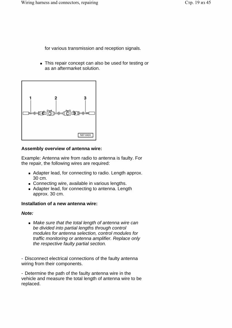
for various transmission and reception signals.
This repair concept can also be used for testing or as an aftermarket solution.
Assembly overview of antenna wire:
Example: Antenna wire from radio to antenna is faulty. For the repair, the following wires are required:
Adapter lead, for connecting to radio. Length approx. 30 cm. Connecting wire, available in various lengths. Adapter lead, for connecting to antenna. Length approx. 30 cm.
Installation of a new antenna wire:
Note:
Make sure that the total length of antenna wire can be divided into partial lengths through control modules for antenna selection, control modules for traffic monitoring or antenna amplifier. Replace only the respective faulty partial section.
- Disconnect electrical connections of the faulty antenna wiring from their components.
- Determine the path of the faulty antenna wire in the vehicle and measure the total length of antenna wire to be replaced.
Стр. 19 из 45Wiring harness and connectors, repairing
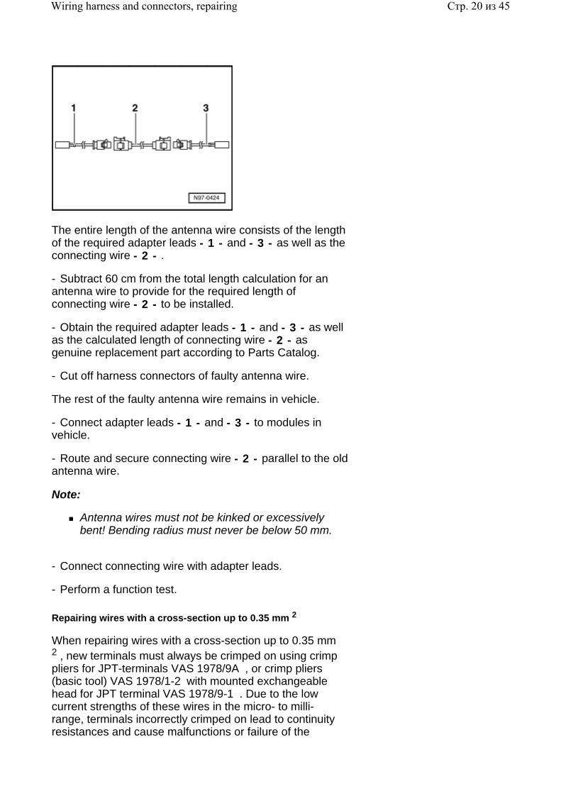
The entire length of the antenna wire consists of the length of the required adapter leads - 1 - and - 3 - as well as the connecting wire - 2 - .
- Subtract 60 cm from the total length calculation for an antenna wire to provide for the required length of connecting wire - 2 - to be installed.
- Obtain the required adapter leads - 1 - and - 3 - as well as the calculated length of connecting wire - 2 - as genuine replacement part according to Parts Catalog.
- Cut off harness connectors of faulty antenna wire.
The rest of the faulty antenna wire remains in vehicle.
- Connect adapter leads - 1 - and - 3 - to modules in vehicle.
- Route and secure connecting wire - 2 - parallel to the old antenna wire.
Note:
Antenna wires must not be kinked or excessively bent! Bending radius must never be below 50 mm.
- Connect connecting wire with adapter leads.
- Perform a function test.
Repairing wires with a cross-section up to 0.35 mm 2
When repairing wires with a cross-section up to 0.35 mm 2 , new terminals must always be crimped on using crimp pliers for JPT-terminals VAS 1978/9A , or crimp pliers (basic tool) VAS 1978/1-2 with mounted exchangeable head for JPT terminal VAS 1978/9-1 . Due to the low current strengths of these wires in the micro- to milli- range, terminals incorrectly crimped on lead to continuity resistances and cause malfunctions or failure of the
Стр. 20 из 45Wiring harness and connectors, repairing
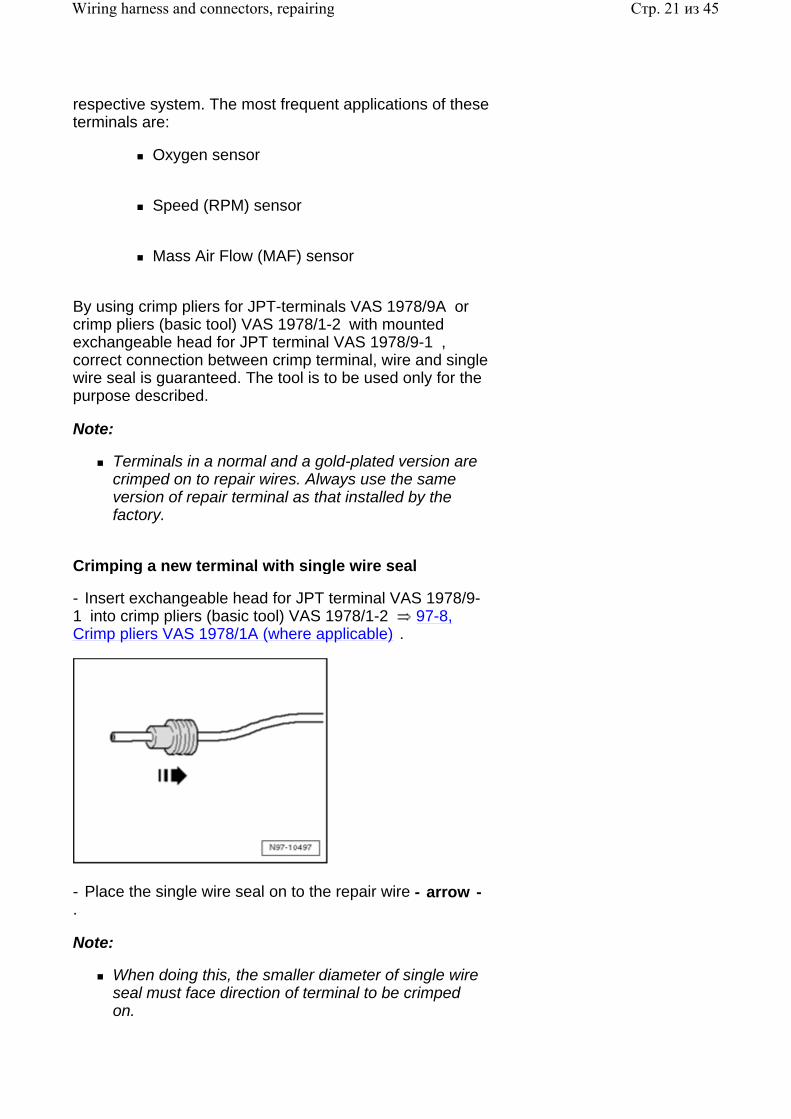
respective system. The most frequent applications of these terminals are:
Oxygen sensor
Speed (RPM) sensor
Mass Air Flow (MAF) sensor
By using crimp pliers for JPT-terminals VAS 1978/9A or crimp pliers (basic tool) VAS 1978/1-2 with mounted exchangeable head for JPT terminal VAS 1978/9-1 , correct connection between crimp terminal, wire and single wire seal is guaranteed. The tool is to be used only for the purpose described.
Note:
Terminals in a normal and a gold-plated version are crimped on to repair wires. Always use the same version of repair terminal as that installed by the factory.
Crimping a new terminal with single wire seal
- Insert exchangeable head for JPT terminal VAS 1978/9-1 into crimp pliers (basic tool) VAS 1978/1-2 97-8, Crimp pliers VAS 1978/1A (where applicable) .
- Place the single wire seal on to the repair wire - arrow - .
Note:
When doing this, the smaller diameter of single wire seal must face direction of terminal to be crimped on.
Стр. 21 из 45Wiring harness and connectors, repairing
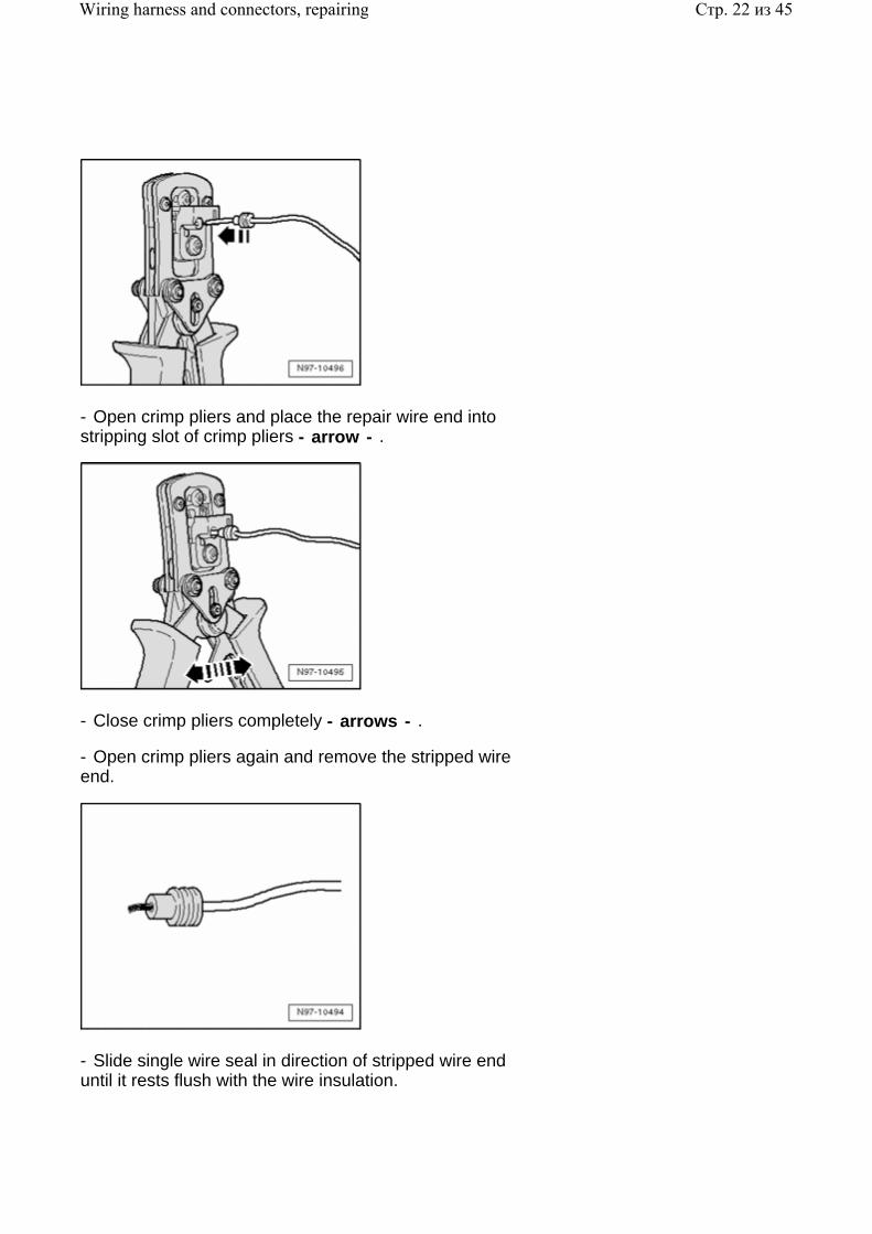
- Open crimp pliers and place the repair wire end into stripping slot of crimp pliers - arrow - .
- Close crimp pliers completely - arrows - .
- Open crimp pliers again and remove the stripped wire end.
- Slide single wire seal in direction of stripped wire end until it rests flush with the wire insulation.
Стр. 22 из 45Wiring harness and connectors, repairing
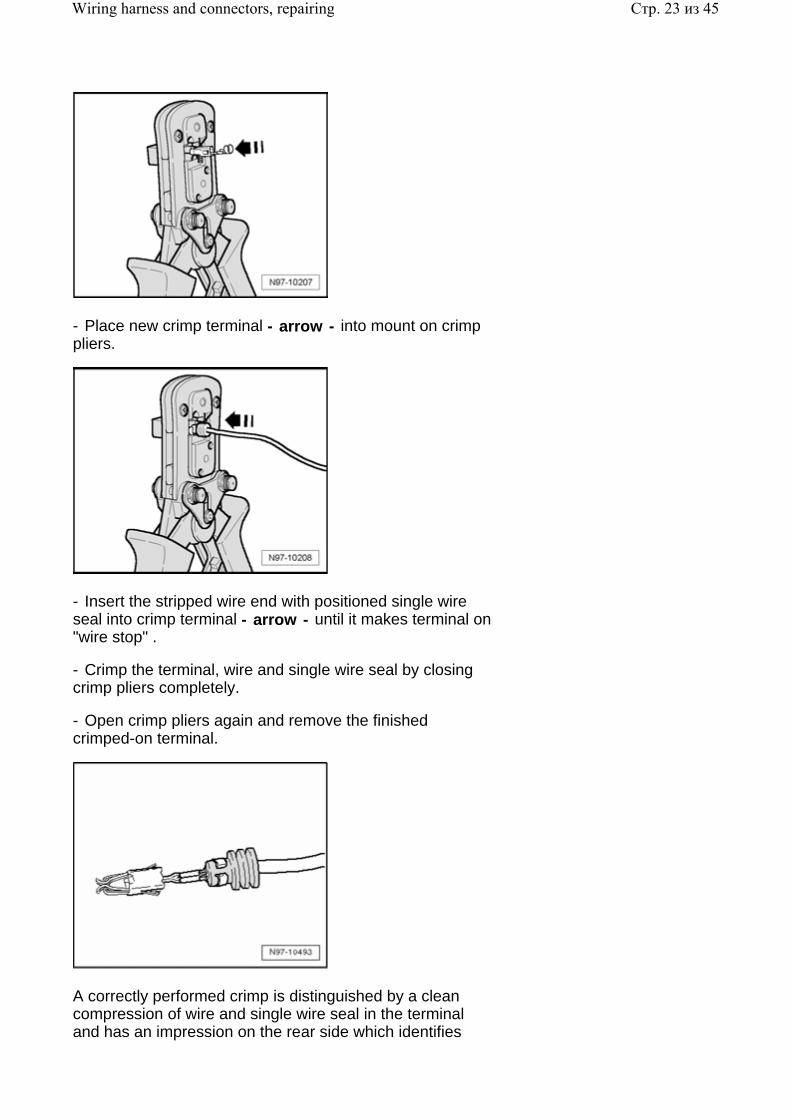
- Place new crimp terminal - arrow - into mount on crimp pliers.
- Insert the stripped wire end with positioned single wire seal into crimp terminal - arrow - until it makes terminal on "wire stop" .
- Crimp the terminal, wire and single wire seal by closing crimp pliers completely.
- Open crimp pliers again and remove the finished crimped-on terminal.
A correctly performed crimp is distinguished by a clean compression of wire and single wire seal in the terminal and has an impression on the rear side which identifies
Стр. 23 из 45Wiring harness and connectors, repairing
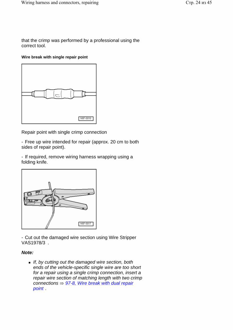
that the crimp was performed by a professional using the correct tool.
Wire break with single repair point
Repair point with single crimp connection
- Free up wire intended for repair (approx. 20 cm to both sides of repair point).
- If required, remove wiring harness wrapping using a folding knife.
- Cut out the damaged wire section using Wire Stripper VAS1978/3 .
Note:
If, by cutting out the damaged wire section, both ends of the vehicle-specific single wire are too short for a repair using a single crimp connection, insert a repair wire section of matching length with two crimp connections 97-8, Wire break with dual repair point .
Стр. 24 из 45Wiring harness and connectors, repairing
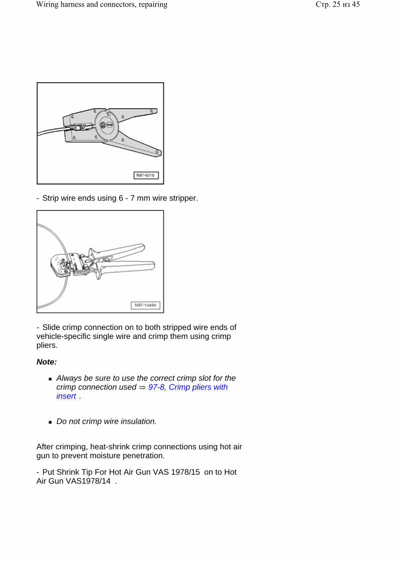
- Strip wire ends using 6 - 7 mm wire stripper.
- Slide crimp connection on to both stripped wire ends of vehicle-specific single wire and crimp them using crimp pliers.
Note:
Always be sure to use the correct crimp slot for the crimp connection used 97-8, Crimp pliers with insert .
Do not crimp wire insulation.
After crimping, heat-shrink crimp connections using hot air gun to prevent moisture penetration.
- Put Shrink Tip For Hot Air Gun VAS 1978/15 on to Hot Air Gun VAS1978/14 .
Стр. 25 из 45Wiring harness and connectors, repairing
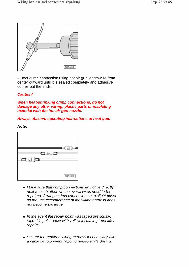
- Heat crimp connection using hot air gun lengthwise from center outward until it is sealed completely and adhesive comes out the ends.
Caution!
When heat-shrinking crimp connections, do not damage any other wiring, plastic parts or insulating material with the hot air gun nozzle.
Always observe operating instructions of heat gun.
Note:
Make sure that crimp connections do not lie directly next to each other when several wires need to be repaired. Arrange crimp connections at a slight offset so that the circumference of the wiring harness does not become too large.
In the event the repair point was taped previously, tape this point anew with yellow insulating tape after repairs.
Secure the repaired wiring harness if necessary with a cable tie to prevent flapping noises while driving.
Стр. 26 из 45Wiring harness and connectors, repairing
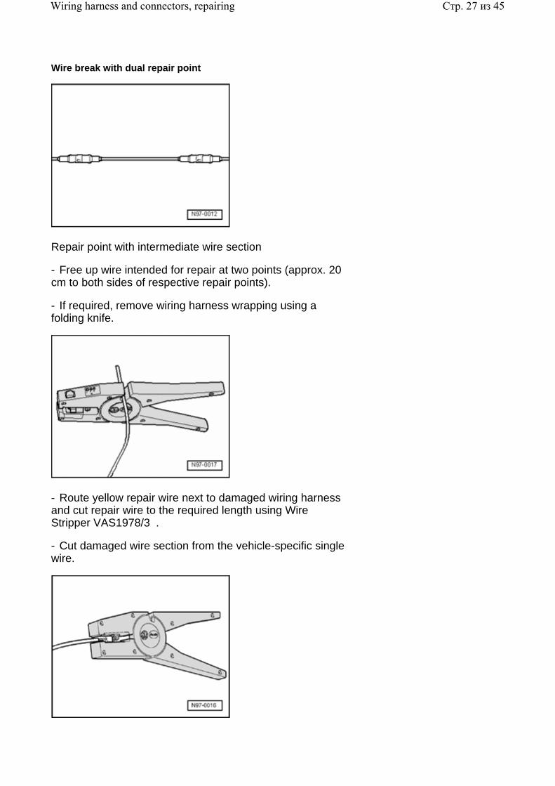
Wire break with dual repair point
Repair point with intermediate wire section
- Free up wire intended for repair at two points (approx. 20 cm to both sides of respective repair points).
- If required, remove wiring harness wrapping using a folding knife.
- Route yellow repair wire next to damaged wiring harness and cut repair wire to the required length using Wire Stripper VAS1978/3 .
- Cut damaged wire section from the vehicle-specific single wire.
Стр. 27 из 45Wiring harness and connectors, repairing
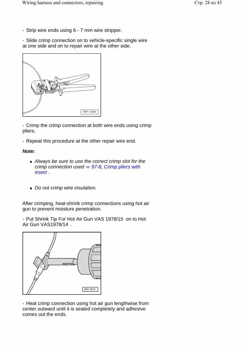
- Strip wire ends using 6 - 7 mm wire stripper.
- Slide crimp connection on to vehicle-specific single wire at one side and on to repair wire at the other side.
- Crimp the crimp connection at both wire ends using crimp pliers.
- Repeat this procedure at the other repair wire end.
Note:
Always be sure to use the correct crimp slot for the crimp connection used 97-8, Crimp pliers with insert .
Do not crimp wire insulation.
After crimping, heat-shrink crimp connections using hot air gun to prevent moisture penetration.
- Put Shrink Tip For Hot Air Gun VAS 1978/15 on to Hot Air Gun VAS1978/14 .
- Heat crimp connection using hot air gun lengthwise from center outward until it is sealed completely and adhesive comes out the ends.
Стр. 28 из 45Wiring harness and connectors, repairing
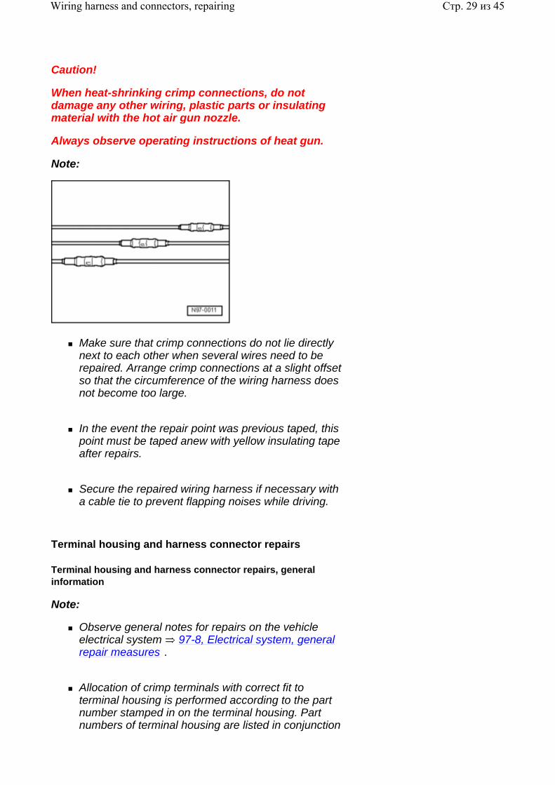
Caution!
When heat-shrinking crimp connections, do not damage any other wiring, plastic parts or insulating material with the hot air gun nozzle.
Always observe operating instructions of heat gun.
Note:
Make sure that crimp connections do not lie directly next to each other when several wires need to be repaired. Arrange crimp connections at a slight offset so that the circumference of the wiring harness does not become too large.
In the event the repair point was previous taped, this point must be taped anew with yellow insulating tape after repairs.
Secure the repaired wiring harness if necessary with a cable tie to prevent flapping noises while driving.
Terminal housing and harness connector repairs
Terminal housing and harness connector repairs, general information
Note:
Observe general notes for repairs on the vehicle electrical system 97-8, Electrical system, general repair measures .
Allocation of crimp terminals with correct fit to terminal housing is performed according to the part number stamped in on the terminal housing. Part numbers of terminal housing are listed in conjunction
Стр. 29 из 45Wiring harness and connectors, repairing
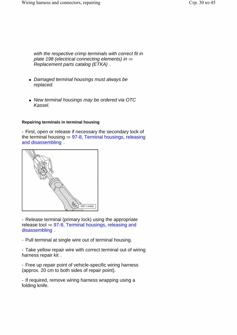
with the respective crimp terminals with correct fit in plate 198 (electrical connecting elements) in Replacement parts catalog (ETKA) .
Damaged terminal housings must always be replaced.
New terminal housings may be ordered via OTC Kassel.
Repairing terminals in terminal housing
- First, open or release if necessary the secondary lock of the terminal housing 97-8, Terminal housings, releasing and disassembling .
- Release terminal (primary lock) using the appropriate release tool 97-8, Terminal housings, releasing and disassembling .
- Pull terminal at single wire out of terminal housing.
- Take yellow repair wire with correct terminal out of wiring harness repair kit .
- Free up repair point of vehicle-specific wiring harness (approx. 20 cm to both sides of repair point).
- If required, remove wiring harness wrapping using a folding knife.
Стр. 30 из 45Wiring harness and connectors, repairing
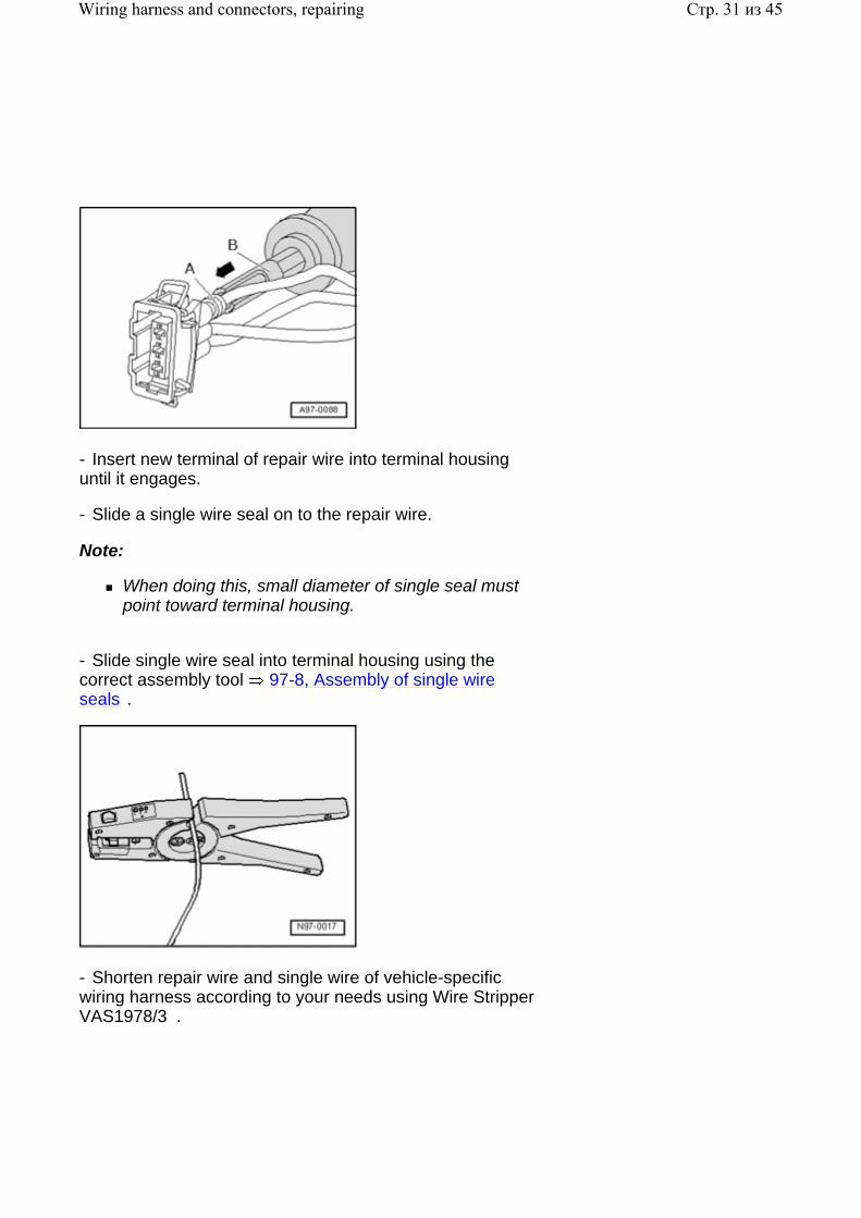
- Insert new terminal of repair wire into terminal housing until it engages.
- Slide a single wire seal on to the repair wire.
Note:
When doing this, small diameter of single seal must point toward terminal housing.
- Slide single wire seal into terminal housing using the correct assembly tool 97-8, Assembly of single wire seals .
- Shorten repair wire and single wire of vehicle-specific wiring harness according to your needs using Wire Stripper VAS1978/3 .
Стр. 31 из 45Wiring harness and connectors, repairing
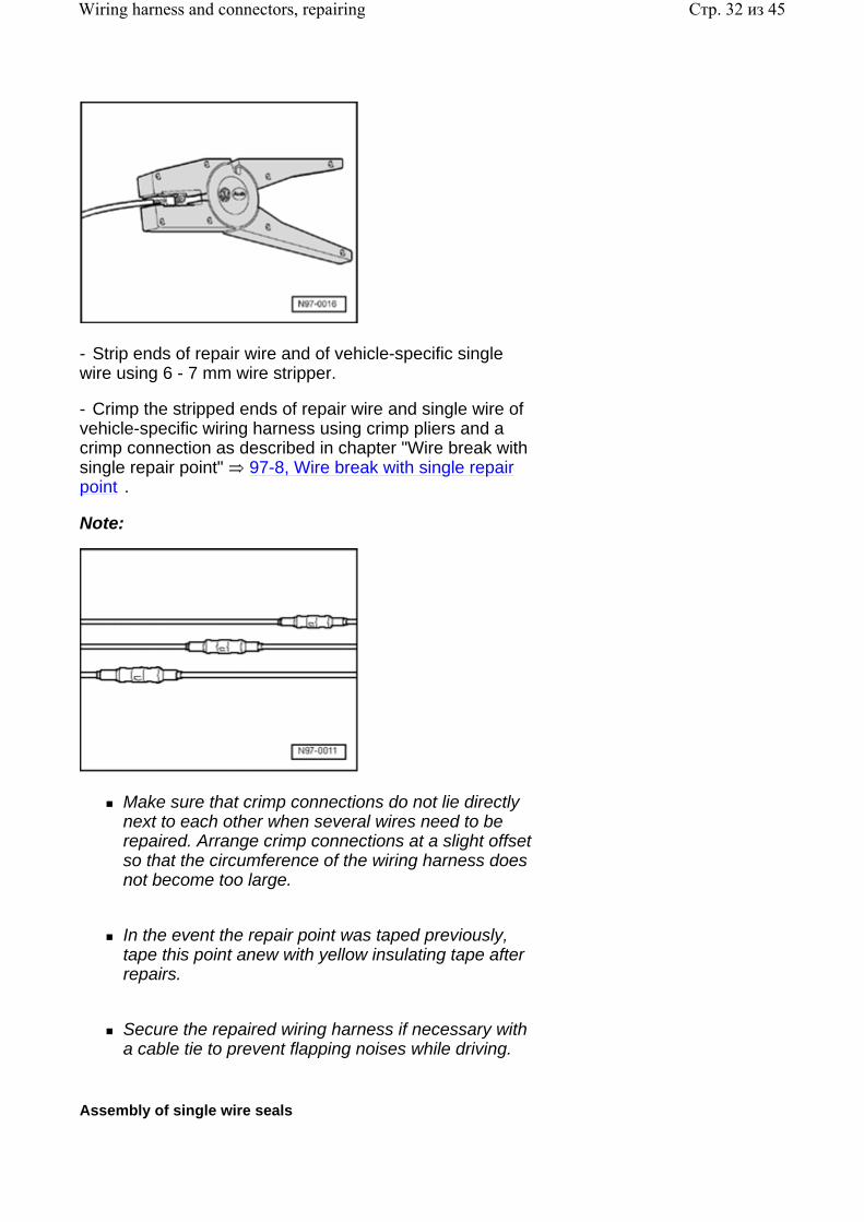
- Strip ends of repair wire and of vehicle-specific single wire using 6 - 7 mm wire stripper.
- Crimp the stripped ends of repair wire and single wire of vehicle-specific wiring harness using crimp pliers and a crimp connection as described in chapter "Wire break with single repair point" 97-8, Wire break with single repair point .
Note:
Make sure that crimp connections do not lie directly next to each other when several wires need to be repaired. Arrange crimp connections at a slight offset so that the circumference of the wiring harness does not become too large.
In the event the repair point was taped previously, tape this point anew with yellow insulating tape after repairs.
Secure the repaired wiring harness if necessary with a cable tie to prevent flapping noises while driving.
Assembly of single wire seals
Стр. 32 из 45Wiring harness and connectors, repairing
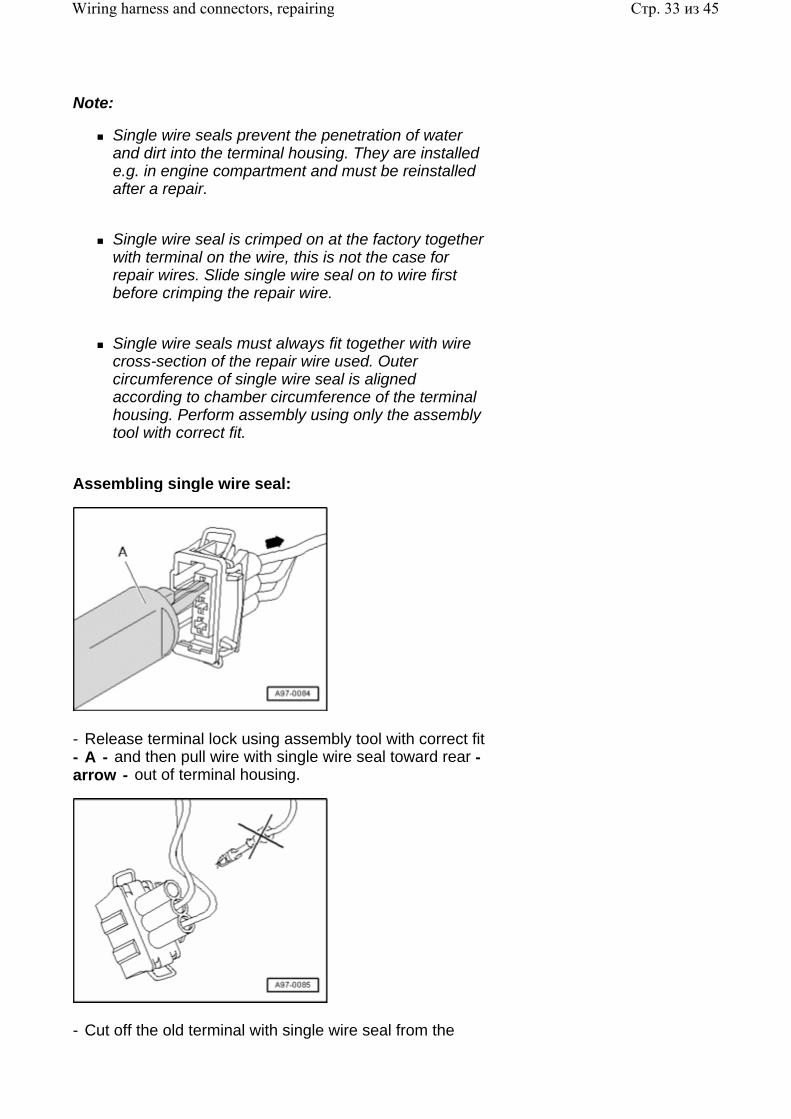
Note:
Single wire seals prevent the penetration of water and dirt into the terminal housing. They are installed e.g. in engine compartment and must be reinstalled after a repair.
Single wire seal is crimped on at the factory together with terminal on the wire, this is not the case for repair wires. Slide single wire seal on to wire first before crimping the repair wire.
Single wire seals must always fit together with wire cross-section of the repair wire used. Outer circumference of single wire seal is aligned according to chamber circumference of the terminal housing. Perform assembly using only the assembly tool with correct fit.
Assembling single wire seal:
- Release terminal lock using assembly tool with correct fit - A - and then pull wire with single wire seal toward rear - arrow - out of terminal housing.
- Cut off the old terminal with single wire seal from the
Стр. 33 из 45Wiring harness and connectors, repairing
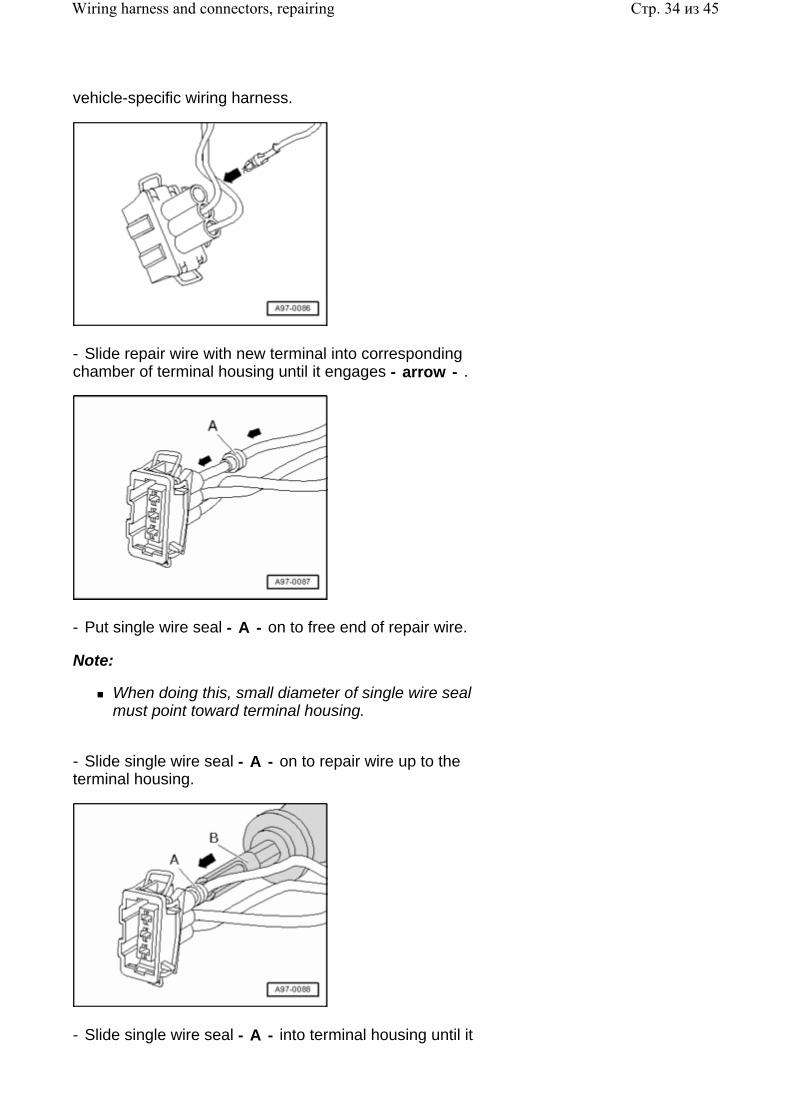
vehicle-specific wiring harness.
- Slide repair wire with new terminal into corresponding chamber of terminal housing until it engages - arrow - .
- Put single wire seal - A - on to free end of repair wire.
Note:
When doing this, small diameter of single wire seal must point toward terminal housing.
- Slide single wire seal - A - on to repair wire up to the terminal housing.
- Slide single wire seal - A - into terminal housing until it
Стр. 34 из 45Wiring harness and connectors, repairing
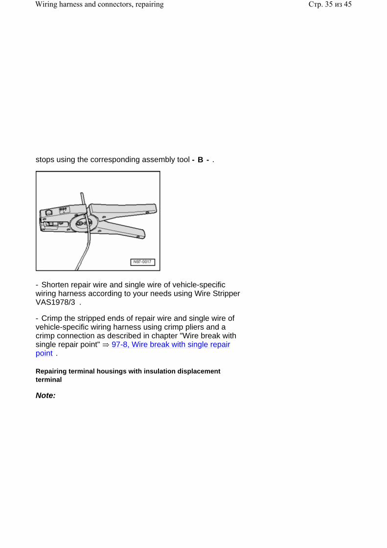
stops using the corresponding assembly tool - B - .
- Shorten repair wire and single wire of vehicle-specific wiring harness according to your needs using Wire Stripper VAS1978/3 .
- Crimp the stripped ends of repair wire and single wire of vehicle-specific wiring harness using crimp pliers and a crimp connection as described in chapter "Wire break with single repair point" 97-8, Wire break with single repair point .
Repairing terminal housings with insulation displacement terminal
Note:
Стр. 35 из 45Wiring harness and connectors, repairing
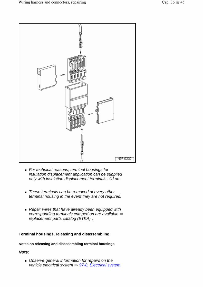
For technical reasons, terminal housings for insulation displacement application can be supplied only with insulation displacement terminals slid on.
These terminals can be removed at every other terminal housing in the event they are not required.
Repair wires that have already been equipped with corresponding terminals crimped on are available replacement parts catalog (ETKA) .
Terminal housings, releasing and disassembling
Notes on releasing and disassembling terminal housings
Note:
Observe general information for repairs on the vehicle electrical system 97-8, Electrical system,
Стр. 36 из 45Wiring harness and connectors, repairing
general repair measures .
Always use the release tools intended for the releasing process. Under no circumstances may terminals be pulled forcefully out of terminal housings.
Damaged terminal housings must always be replaced. New terminal housings may be ordered via OTC Kassel.
Small screwdrivers may be used as an aid to release the secondary locks.
Chamber/pin assignment is located partially stamped in on secondary lock or rear side of terminal housing.
Detailed information on component locations of harness connectors Electrical Wiring Diagrams, Troubleshooting and Component Locations binder .
The application of the correct release tools to the respective locks can be found in the table in users instructions for Release Tool Set VAS1978/35 .
Secondary lock
The secondary lock is a housing securing mechanism (second locking mechanism) that secures all wires in a terminal housing. If a secondary lock is installed at a terminal housing, it must always be opened or removed using specified tool before releasing and pulling out individual crimp terminals.
Secondary lock is distinguished by a different color from the rest of the terminal housing. It simplifies recognizing the secondary lock and clarifies its function.
The shapes of the terminal housings depicted here are only a selection which, as an example, should make clear the various functions of the secondary lock.
Стр. 37 из 45Wiring harness and connectors, repairing
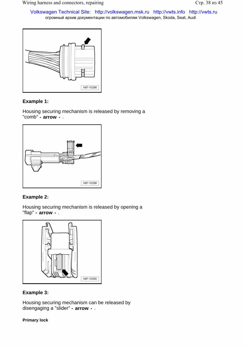
Example 1:
Housing securing mechanism is released by removing a "comb" - arrow - .
Example 2:
Housing securing mechanism is released by opening a "flap" - arrow - .
Example 3:
Housing securing mechanism can be released by disengaging a "slider" - arrow - .
Primary lock
Стр. 38 из 45Wiring harness and connectors, repairing
Volkswagen Technical Site: http://volkswagen.msk.ru http://vwts.info http://vwts.ru огромный архив документации по автомобилям Volkswagen, Skoda, Seat, Audi
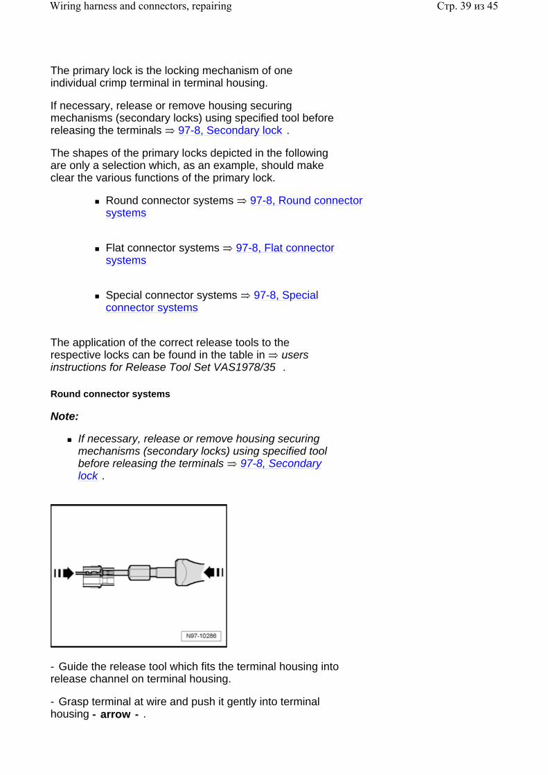
The primary lock is the locking mechanism of one individual crimp terminal in terminal housing.
If necessary, release or remove housing securing mechanisms (secondary locks) using specified tool before releasing the terminals 97-8, Secondary lock .
The shapes of the primary locks depicted in the following are only a selection which, as an example, should make clear the various functions of the primary lock.
Round connector systems 97-8, Round connector systems
Flat connector systems 97-8, Flat connector systems
Special connector systems 97-8, Special connector systems
The application of the correct release tools to the respective locks can be found in the table in users instructions for Release Tool Set VAS1978/35 .
Round connector systems
Note:
If necessary, release or remove housing securing mechanisms (secondary locks) using specified tool before releasing the terminals 97-8, Secondary lock .
- Guide the release tool which fits the terminal housing into release channel on terminal housing.
- Grasp terminal at wire and push it gently into terminal housing - arrow - .
Стр. 39 из 45Wiring harness and connectors, repairing
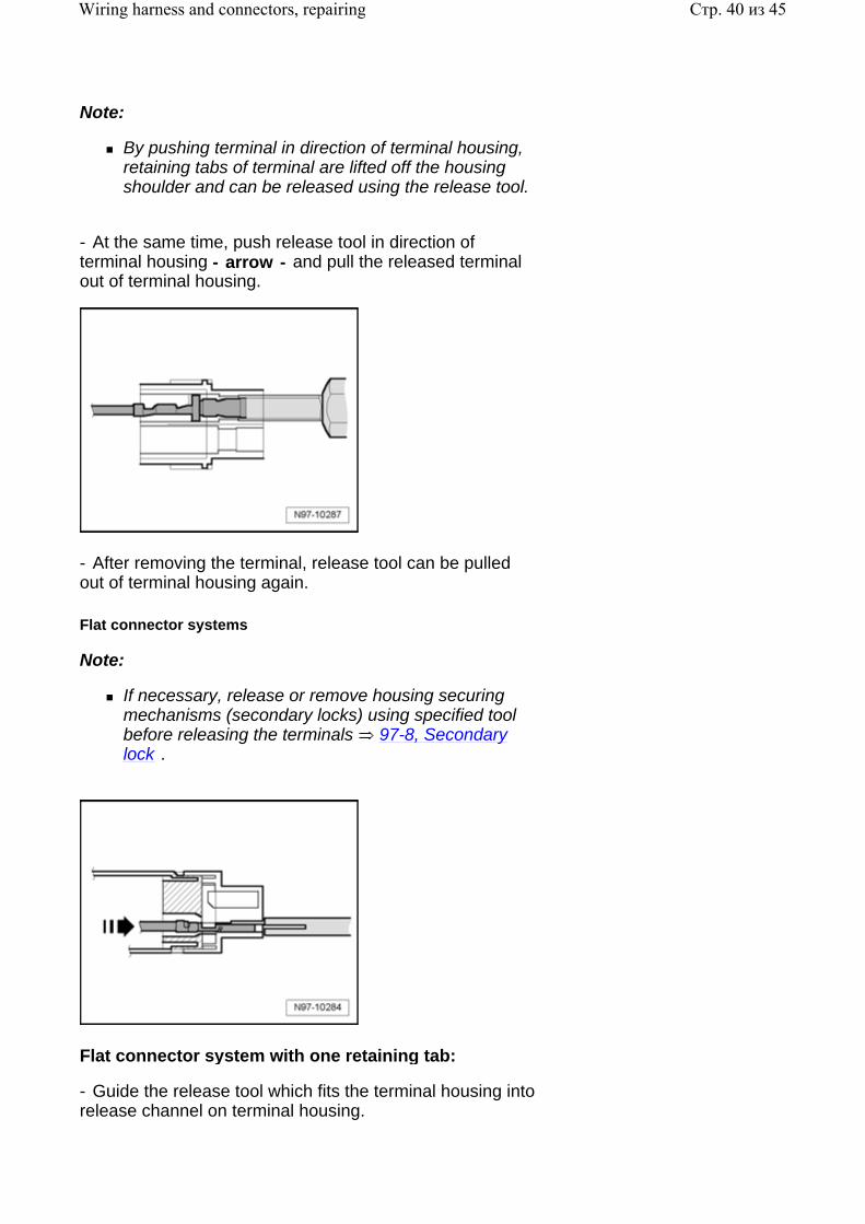
Note:
By pushing terminal in direction of terminal housing, retaining tabs of terminal are lifted off the housing shoulder and can be released using the release tool.
- At the same time, push release tool in direction of terminal housing - arrow - and pull the released terminal out of terminal housing.
- After removing the terminal, release tool can be pulled out of terminal housing again.
Flat connector systems
Note:
If necessary, release or remove housing securing mechanisms (secondary locks) using specified tool before releasing the terminals 97-8, Secondary lock .
Flat connector system with one retaining tab:
- Guide the release tool which fits the terminal housing into release channel on terminal housing.
Стр. 40 из 45Wiring harness and connectors, repairing
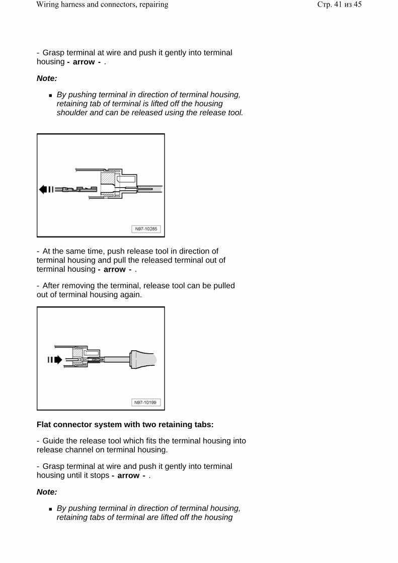
- Grasp terminal at wire and push it gently into terminal housing - arrow - .
Note:
By pushing terminal in direction of terminal housing, retaining tab of terminal is lifted off the housing shoulder and can be released using the release tool.
- At the same time, push release tool in direction of terminal housing and pull the released terminal out of terminal housing - arrow - .
- After removing the terminal, release tool can be pulled out of terminal housing again.
Flat connector system with two retaining tabs:
- Guide the release tool which fits the terminal housing into release channel on terminal housing.
- Grasp terminal at wire and push it gently into terminal housing until it stops - arrow - .
Note:
By pushing terminal in direction of terminal housing, retaining tabs of terminal are lifted off the housing
Стр. 41 из 45Wiring harness and connectors, repairing
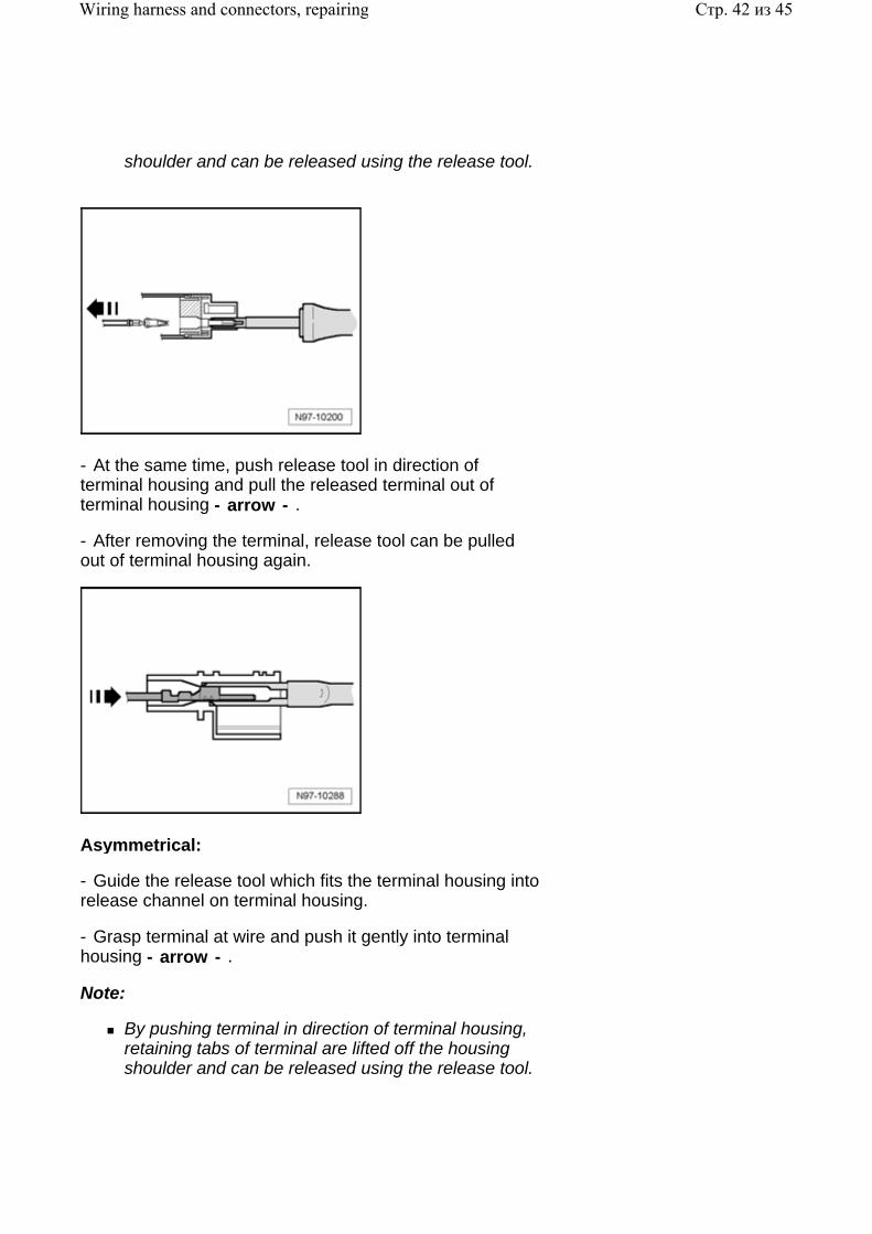
shoulder and can be released using the release tool.
- At the same time, push release tool in direction of terminal housing and pull the released terminal out of terminal housing - arrow - .
- After removing the terminal, release tool can be pulled out of terminal housing again.
Asymmetrical:
- Guide the release tool which fits the terminal housing into release channel on terminal housing.
- Grasp terminal at wire and push it gently into terminal housing - arrow - .
Note:
By pushing terminal in direction of terminal housing, retaining tabs of terminal are lifted off the housing shoulder and can be released using the release tool.
Стр. 42 из 45Wiring harness and connectors, repairing
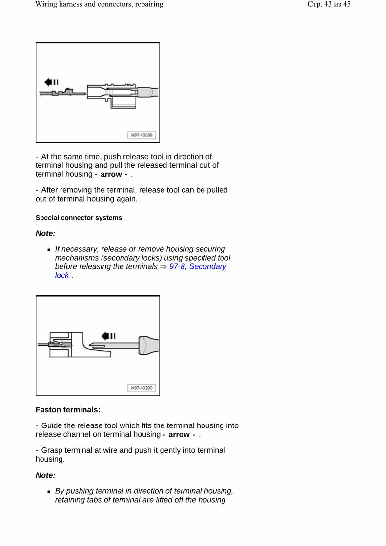
- At the same time, push release tool in direction of terminal housing and pull the released terminal out of terminal housing - arrow - .
- After removing the terminal, release tool can be pulled out of terminal housing again.
Special connector systems
Note:
If necessary, release or remove housing securing mechanisms (secondary locks) using specified tool before releasing the terminals 97-8, Secondary lock .
Faston terminals:
- Guide the release tool which fits the terminal housing into release channel on terminal housing - arrow - .
- Grasp terminal at wire and push it gently into terminal housing.
Note:
By pushing terminal in direction of terminal housing, retaining tabs of terminal are lifted off the housing
Стр. 43 из 45Wiring harness and connectors, repairing
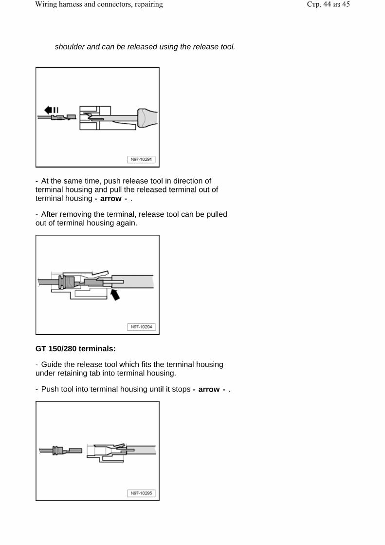
shoulder and can be released using the release tool.
- At the same time, push release tool in direction of terminal housing and pull the released terminal out of terminal housing - arrow - .
- After removing the terminal, release tool can be pulled out of terminal housing again.
GT 150/280 terminals:
- Guide the release tool which fits the terminal housing under retaining tab into terminal housing.
- Push tool into terminal housing until it stops - arrow - .
Стр. 44 из 45Wiring harness and connectors, repairing
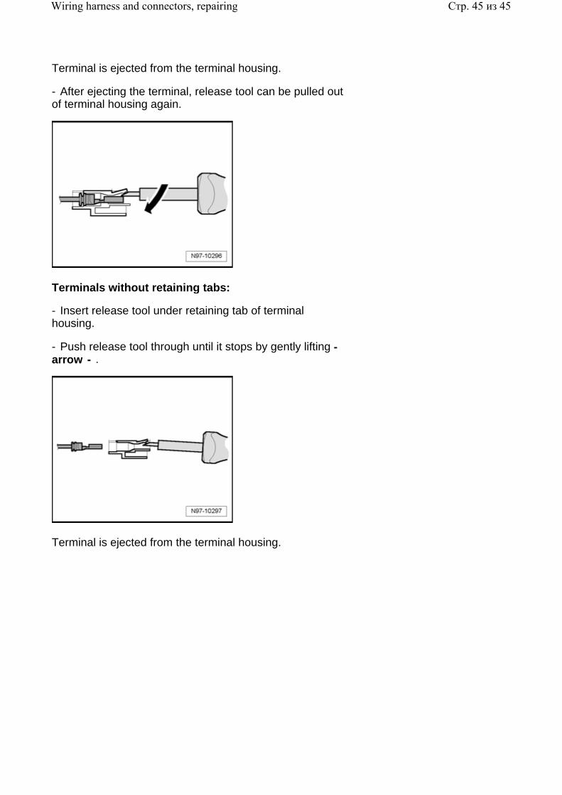
Terminal is ejected from the terminal housing.
- After ejecting the terminal, release tool can be pulled out of terminal housing again.
Terminals without retaining tabs:
- Insert release tool under retaining tab of terminal housing.
- Push release tool through until it stops by gently lifting - arrow - .
Terminal is ejected from the terminal housing.
Стр. 45 из 45Wiring harness and connectors, repairing