vlt® ethernet/ip mca 121 - files.danfoss.comfiles.danfoss.com/download/drives/mg90j502.pdf · 2...
TRANSCRIPT

MAKING MODERN LIVING POSSIBLE
Installation GuideVLT® EtherNet/IP MCA 121VLT® HVAC Drive FC 102 • VLT® AQUA Drive FC 202VLT® AutomationDrive FC 301/302
www.danfoss.com/drives


Contents
1 Introduction 2
1.1 Purpose of the Manual 2
1.2 Additional Resources 2
1.3 Product Overview 2
1.4 Approvals and Certifications 2
1.5 Disposal 3
1.6 Symbols, Abbreviations and Conventions 3
2 Safety 4
2.1 Safety Symbols 4
2.2 Qualified Personnel 4
2.3 Safety Precautions 4
3 Installation 6
3.1 Safety Instructions 6
3.2 EMC-compliant Installation 6
3.3 Grounding 6
3.4 Cable Routing 6
3.5 Topology 7
3.6 Mounting 8
3.7 Electrical Installation 10
3.8 Reassembling the Cover 12
3.9 Applying Power 12
3.10 Checking Network Cabling 12
4 Troubleshooting 13
4.1 Warnings and Alarms 13
4.2 Troubleshooting 13
4.2.1 LED Status 13
4.2.2 No Communication with the Frequency Converter 14
Index 15
Contents Installation Guide
MG90J502 Danfoss A/S © 11/2014 All rights reserved. 1
1 Introduction
1.1 Purpose of the Manual
This installation guide provides information for the quickinstallation of a VLT® EtherNet/IP MCA 121 interface in aVLT® frequency converter.The installation guide is intended for use by qualifiedpersonnel. Users are assumed to be familiar with:
• VLT® frequency converter.
• EtherNet/IP technology.
• PC or PLC that is used as a master in the system.
Read the instructions before installation and ensure thatthe instructions for safe installation are observed.
VLT® is a registered trademark.
1.2 Additional Resources
Resources available for the frequency converters andoptional equipment:
• The relevant frequency converter OperatingInstructions provide the necessary information forgetting the frequency converter up and running.
• The relevant frequency converter Design Guideprovides detailed information about capabilitiesand functionality to design motor controlsystems.
• The relevant frequency converter ProgrammingGuide provides greater detail on working withparameters and many application examples.
• The VLT® EtherNet/IP MCA 121 Installation Guideprovides information about installing theEtherNet/IP and troubleshooting.
• The VLT® EtherNet/IP MCA 121 Programming Guideprovides information about configuring thesystem, controlling the frequency converter,parameter access, programming, troubleshooting,as well as some typical application examples.
Supplementary publications and manuals are availablefrom Danfoss. See www.danfoss.com/BusinessAreas/DrivesSo-lutions/Documentations/VLT+Technical+Documentation.htmfor listings.
1.3 Product Overview
1.3.1 Intended Use
This installation guide relates to EtherNet/IP interface.Ordering number:
• 130B1119 (uncoated)
• 130B1219 (conformal coated)
The EtherNet/IP interface is designed to communicate withany system complying with the CIP EtherNet/IP standard.EtherNet/IP provides users with the network tools todeploy standard Ethernet technology for manufacturingapplications while enabling Internet and enterpriseconnectivity.
VLT® EtherNet/IP MCA 121 is intended for use with:
• VLT® HVAC Drive FC 102
• VLT® AQUA Drive FC 202
• VLT® AutomationDrive FC 301
• VLT® AutomationDrive FC 302
1.3.2 Items Supplied
When the fieldbus option is not factory mounted, thefollowing items are supplied:
• Fieldbus option
• LCP cradle
• Front covers (in various sizes)
• Stickers
• Accessories bag
• Strain relief (only for A1 and A2 enclosures)
• Installation Guide
1.4 Approvals and Certifications
More approvals and certifications are available. For moreinformation, contact a Danfoss local partner.
Introduction VLT® EtherNet/IP MCA 121
2 Danfoss A/S © 11/2014 All rights reserved. MG90J502
11
1.5 Disposal
Do not dispose of equipment containingelectrical components together withdomestic waste.Collect it separately in accordance withlocal and currently valid legislation.
1.6 Symbols, Abbreviations andConventions
Abbreviation Definition
CIPTM Common industrial protocol
DHCP Dynamic host configuration protocol
EIP EtherNet/IP
EMC Electromagnetic compatibility
IP Internet protocol
LCP Local control panel
LED Light emitting diode
MAR Major recoverable fail
MAU Major unrecoverable fail
PC Personal computer
PLC Programmable logic controller
TCP Transmission control protocol
Table 1.1 Symbols and Abbreviations
ConventionsNumbered lists indicate procedures.Bullet lists indicate other information and description ofillustrations.Italicised text indicates:
• Cross reference
• Link
• Parameter name
Introduction Installation Guide
MG90J502 Danfoss A/S © 11/2014 All rights reserved. 3
1 1

2 Safety
2.1 Safety Symbols
The following symbols are used in this document:
WARNINGIndicates a potentially hazardous situation that couldresult in death or serious injury.
CAUTIONIndicates a potentially hazardous situation that couldresult in minor or moderate injury. It can also be used toalert against unsafe practices.
NOTICEIndicates important information, including situations thatcan result in damage to equipment or property.
2.2 Qualified Personnel
Correct and reliable transport, storage, installation,operation, and maintenance are required for the trouble-free and safe operation of the frequency converter. Onlyqualified personnel are allowed to install or operate thisequipment.
Qualified personnel are defined as trained staff, who areauthorised to install, commission, and maintain equipment,systems, and circuits in accordance with pertinent laws andregulations. Additionally, the qualified personnel must befamiliar with the instructions and safety measuresdescribed in this installation guide.
2.3 Safety Precautions
WARNINGHIGH VOLTAGEFrequency converters contain high voltage whenconnected to AC mains input, DC supply, or load sharing.Failure to perform installation, start-up, and maintenanceby qualified personnel can result in death or seriousinjury.
• Installation, start-up, and maintenance must beperformed by qualified personnel only.
WARNINGUNINTENDED STARTWhen the frequency converter is connected to AC mains,DC power supply, or load sharing, the motor may start atany time. Unintended start during programming, serviceor repair work can result in death, serious injury, orproperty damage. The motor can start by means of anexternal switch, a serial bus command, an inputreference signal from the LCP or LOP, via remoteoperation using MCT 10 software, or after a cleared faultcondition.To prevent unintended motor start:
• Disconnect the frequency converter from themains.
• Press [Off/Reset] on the LCP beforeprogramming parameters.
• The frequency converter, motor, and any drivenequipment must be fully wired and assembledwhen the frequency converter is connected toAC mains, DC power supply, or load sharing.
WARNINGDISCHARGE TIMEThe frequency converter contains DC-link capacitors thatcan remain charged even when the frequency converteris not powered. Failure to wait the specified time afterpower has been removed before performing service orrepair work, can result in death or serious injury.
• Stop the motor.
• Disconnect the AC mains and remote DC-linkpower supplies, including battery back-ups,UPS, and DC-link connections to otherfrequency converters.
• Disconnect or lock the PM motor.
• Wait for the capacitors to discharge fully beforeperforming any service or repair work. Theduration of waiting time is specified in therelevant frequency converter operatinginstructions,Chapter 2 Safety.
Safety VLT® EtherNet/IP MCA 121
4 Danfoss A/S © 11/2014 All rights reserved. MG90J502
22
WARNINGLEAKAGE CURRENT HAZARDLeakage currents exceed 3.5 mA. Failure to ground thefrequency converter properly can result in death orserious injury.
• Ensure the correct grounding of the equipmentby a certified electrical installer.
WARNINGEQUIPMENT HAZARDContact with rotating shafts and electrical equipmentcan result in death or serious injury.
• Ensure that only trained and qualifiedpersonnel perform installation, start up, andmaintenance.
• Ensure that electrical work conforms to nationaland local electrical codes.
• Follow the procedures in this document.
CAUTIONINTERNAL FAILURE HAZARDAn internal failure in the frequency converter can resultin serious injury, when the frequency converter is notproperly closed.
• Ensure that all safety covers are in place andsecurely fastened before applying power.
Safety Installation Guide
MG90J502 Danfoss A/S © 11/2014 All rights reserved. 5
2 2

3 Installation
3.1 Safety Instructions
See chapter 2 Safety for general safety instructions.
3.2 EMC-compliant Installation
To obtain an EMC-compliant installation, follow theinstructions provided in the relevant frequency converterOperating Instructions and Design Guide. Refer to thefieldbus master manual from the PLC supplier for furtherinstallation guidelines.
3.3 Grounding
• Ensure that all stations connected to the fieldbusnetwork are connected to the same groundpotential. When there are long distances betweenthe stations in a fieldbus network, connect theindividual station to the same ground potential.Install equalising cables between the systemcomponents.
• Establish a grounding connection with low HFimpedance, for example by mounting thefrequency converter on a conductive back plate.
• Keep the ground wire connections as short aspossible.
• Electrical contact between the cable screen andthe frequency converter enclosure or ground isnot allowed in Ethernet installations. The RJ45connector of the Ethernet interface provides anelectrical path for the electrical interference toground.
• Use high-strand wire to reduce electricalinterference.
3.4 Cable Routing
NOTICEEMC INTERFERENCEUse screened cables for motor and control wiring, andseparate cables for fieldbus communication, motorwiring, and brake resistor. Failure to isolate fieldbuscommunication, motor, and brake resistor cables canresult in unintended behaviour or reduced performance.Minimum 200 mm (7.9 in) clearance between power,motor, and control cables is required. For power sizesabove 315 kW, it is recommended to increase theminimum distance of 500 mm (20 in).
NOTICEWhen the fieldbus cable crosses a motor cable or a brakeresistor cable, ensure that the cables cross at an angle of90°.
130B
D86
6.10
≥ 200mm
21
1 Ethernet cable
2 90° crossing
Illustration 3.1 Cable Routing
Installation VLT® EtherNet/IP MCA 121
6 Danfoss A/S © 11/2014 All rights reserved. MG90J502
33
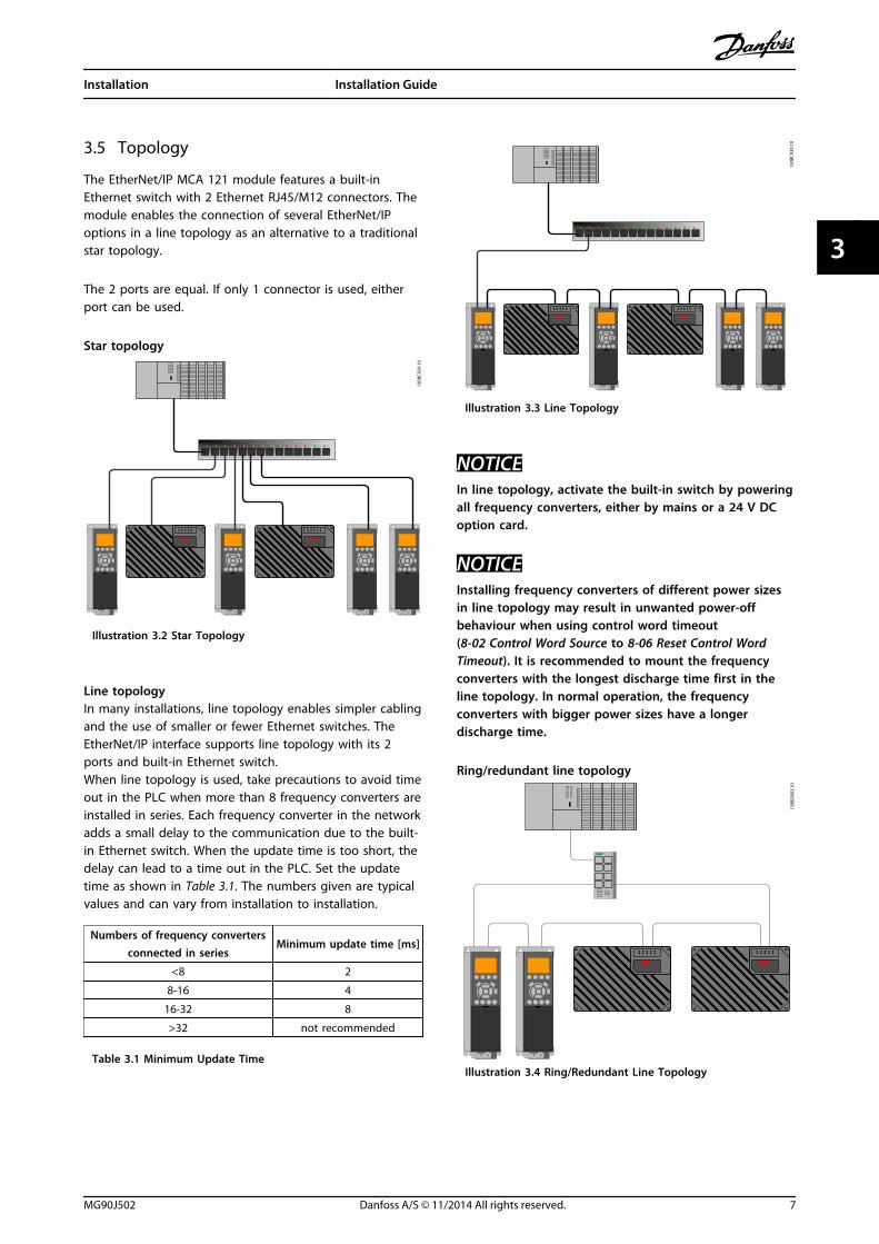
3.5 Topology
The EtherNet/IP MCA 121 module features a built-inEthernet switch with 2 Ethernet RJ45/M12 connectors. Themodule enables the connection of several EtherNet/IPoptions in a line topology as an alternative to a traditionalstar topology.
The 2 ports are equal. If only 1 connector is used, eitherport can be used.
Star topology
130B
C92
9.10
Illustration 3.2 Star Topology
Line topologyIn many installations, line topology enables simpler cablingand the use of smaller or fewer Ethernet switches. TheEtherNet/IP interface supports line topology with its 2ports and built-in Ethernet switch.When line topology is used, take precautions to avoid timeout in the PLC when more than 8 frequency converters areinstalled in series. Each frequency converter in the networkadds a small delay to the communication due to the built-in Ethernet switch. When the update time is too short, thedelay can lead to a time out in the PLC. Set the updatetime as shown in Table 3.1. The numbers given are typicalvalues and can vary from installation to installation.
Numbers of frequency convertersconnected in series
Minimum update time [ms]
<8 2
8-16 4
16-32 8
>32 not recommended
Table 3.1 Minimum Update Time
130B
C93
0.10
Illustration 3.3 Line Topology
NOTICEIn line topology, activate the built-in switch by poweringall frequency converters, either by mains or a 24 V DCoption card.
NOTICEInstalling frequency converters of different power sizesin line topology may result in unwanted power-offbehaviour when using control word timeout(8-02 Control Word Source to 8-06 Reset Control WordTimeout). It is recommended to mount the frequencyconverters with the longest discharge time first in theline topology. In normal operation, the frequencyconverters with bigger power sizes have a longerdischarge time.
Ring/redundant line topology13
0BD
803.
10
Illustration 3.4 Ring/Redundant Line Topology
Installation Installation Guide
MG90J502 Danfoss A/S © 11/2014 All rights reserved. 7
3 3

Ring topology can increase the availability of an Ethernetnetwork.
For ring topology:
• Install a special switch (redundancy manager)between the PLC and the frequency converters.
• Configure the redundancy manager switch toclearly define the ports that connect to the ring.
When the ring operates, the main redundancy managersends test frames into the ring to detect. If the switchdetects a fault in the ring, it reconfigures the ring into 2lines instead. The transition time from 1 ring into 2 lines isup to 500 ms depending on the components installed inthe ring. Set the timing of the PLC to ensure that thetransition time does not lead to a time-out fault.
NOTICEFor ring/redundant line topology, ensure the redundancymanager switch supports the detection of loss of linetopology. The switch inside the EtherNet/IP interfacedoes not support this detection.
Recommended design rules
• Pay special attention to active networkcomponents when designing an Ethernetnetwork.
• For line topology, a small delay is added witheach additional switch in the line. For moreinformation, see Table 3.1.
• Do not connect more than 32 frequencyconverters in series. Exceeding this limit canresult in unstable or faulty communication.
130B
C92
7.10
Illustration 3.5 Recommended Design Rules
3.6 Mounting
1. Check whether the fieldbus option is alreadymounted in the frequency converter. If alreadymounted, go to step 6.
2. Remove the LCP or blind cover from thefrequency converter.
3. Use a screwdriver to remove the front cover andthe LCP cradle.
4. Mount the fieldbus option. Mount the optionwith the Ethernet Port facing up for top cableentry (see Illustration 3.7), or with the EthernetPort facing down for bottom cable entry (seeIllustration 3.8).
5. Remove the knock-out plate from the new LCPcradle.
6. Mount the new LCP cradle.
1
2
3
130B
D90
8.10
1 LCP
2 LCP cradle
3 Fieldbus option
Illustration 3.6 Exploded View
Installation VLT® EtherNet/IP MCA 121
8 Danfoss A/S © 11/2014 All rights reserved. MG90J502
33
130B
D90
9.10
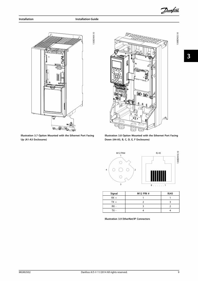
Illustration 3.7 Option Mounted with the Ethernet Port FacingUp (A1-A3 Enclosures)
130B
D92
5.10
Illustration 3.8 Option Mounted with the Ethernet Port FacingDown (A4-A5, B, C, D, E, F Enclosures)
130B
D91
0.10
24
3
M12 PIN# RJ 45
8
1
1. . . . . .
Signal M12 PIN # RJ45
RX + 1 1
TX + 2 3
RX - 3 2
TX - 4 4
Illustration 3.9 EtherNet/IP Connectors
Installation Installation Guide
MG90J502 Danfoss A/S © 11/2014 All rights reserved. 9
3 3
3.7 Electrical Installation
3.7.1 Cabling Requirements
• Choose cables suitable for Ethernet datatransmission. Normally CAT5e and CAT6 cablesare recommended for industrial applications.
• Both types are available as unshielded twistedpair and shielded twisted pair. Screened cablesare recommended for use in industrialenvironments and with frequency converters.
• A maximum cable length of 100 m is allowedbetween the switches.
• Use optical fibres for gapping longer distancesand providing galvanic isolation.
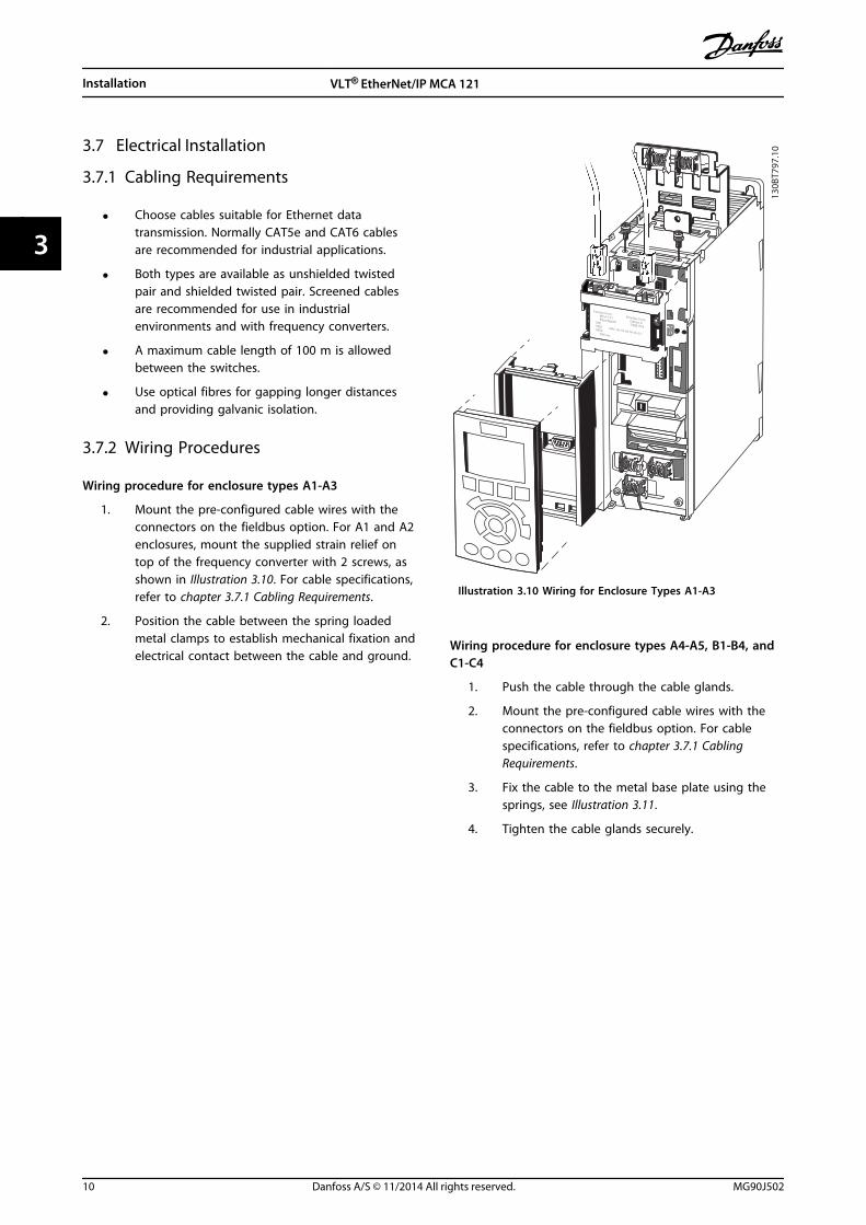
3.7.2 Wiring Procedures
Wiring procedure for enclosure types A1-A3
1. Mount the pre-configured cable wires with theconnectors on the fieldbus option. For A1 and A2enclosures, mount the supplied strain relief ontop of the frequency converter with 2 screws, asshown in Illustration 3.10. For cable specifications,refer to chapter 3.7.1 Cabling Requirements.
2. Position the cable between the spring loadedmetal clamps to establish mechanical fixation andelectrical contact between the cable and ground.
EtherNet Port1 EtherNet Port2
MCA 121 Option A EtherNet/IP 130B1119 MS MS1 MAC-00-1B-08-00-00-22 MS2 SW.ver.
130B
T797
.10
Illustration 3.10 Wiring for Enclosure Types A1-A3
Wiring procedure for enclosure types A4-A5, B1-B4, andC1-C4
1. Push the cable through the cable glands.
2. Mount the pre-configured cable wires with theconnectors on the fieldbus option. For cablespecifications, refer to chapter 3.7.1 CablingRequirements.
3. Fix the cable to the metal base plate using thesprings, see Illustration 3.11.
4. Tighten the cable glands securely.
Installation VLT® EtherNet/IP MCA 121
10 Danfoss A/S © 11/2014 All rights reserved. MG90J502
33

130B
D92
4.10
Illustration 3.11 Wiring for Enclosure Types A4-A5, B1-B4, andC1-C4
Wiring procedure for enclosure types D, E, and F
1. Mount the pre-configured cable wires with theconnectors on the fieldbus option. For cablespecifications, refer to chapter 3.7.1 CablingRequirements.
2. Fix the cable to the metal base plate using thesprings, see Illustration 3.12.
3. Tie down the cable and route it with othercontrol wires inside the unit, see Illustration 3.12.
130B
D92
6.10
Illustration 3.12 Wiring for Enclosure Types D, E, and F
NOTICEDo not strip the Ethernet cable. Do not ground it via thestrain relief plate. Ground the screened Ethernet cablesthrough the RJ45 connector on the EtherNet/IP interface.
Installation Installation Guide
MG90J502 Danfoss A/S © 11/2014 All rights reserved. 11
3 3

3.8 Reassembling the Cover
1. Mount the new front cover and the LCP.
2. Attach the sticker with the correct product nameto the front cover.
3.9 Applying Power
Follow the instructions in the frequency converterOperating Instructions to commission the frequencyconverter. The frequency converter automatically detectsthe EtherNet/IP interface. A new parameter group (Group12) appears.
3.10 Checking Network Cabling
NOTICEAfter installing the EtherNet/IP interface, be aware of thefollowing parameter settings:8-01 Control Site: [2] Control word only or [0] Digital andcontrol word8-02 Control Word Source: [3] Option A
Installation VLT® EtherNet/IP MCA 121
12 Danfoss A/S © 11/2014 All rights reserved. MG90J502
33
4 Troubleshooting
4.1 Warnings and Alarms
NOTICERefer to the relevant frequency converter OperatingInstructions for an overview of warning and alarm types,and for the full list of warnings and alarms.
Alarm word and warning word are shown in the display inHex format. When there is more than 1 warning or alarm,the sum of all warnings or alarms is shown. Warning wordand alarm word are displayed in 16-90 Alarm Word to16-95 Ext. Status Word 2.
4.2 Troubleshooting
4.2.1 LED Status
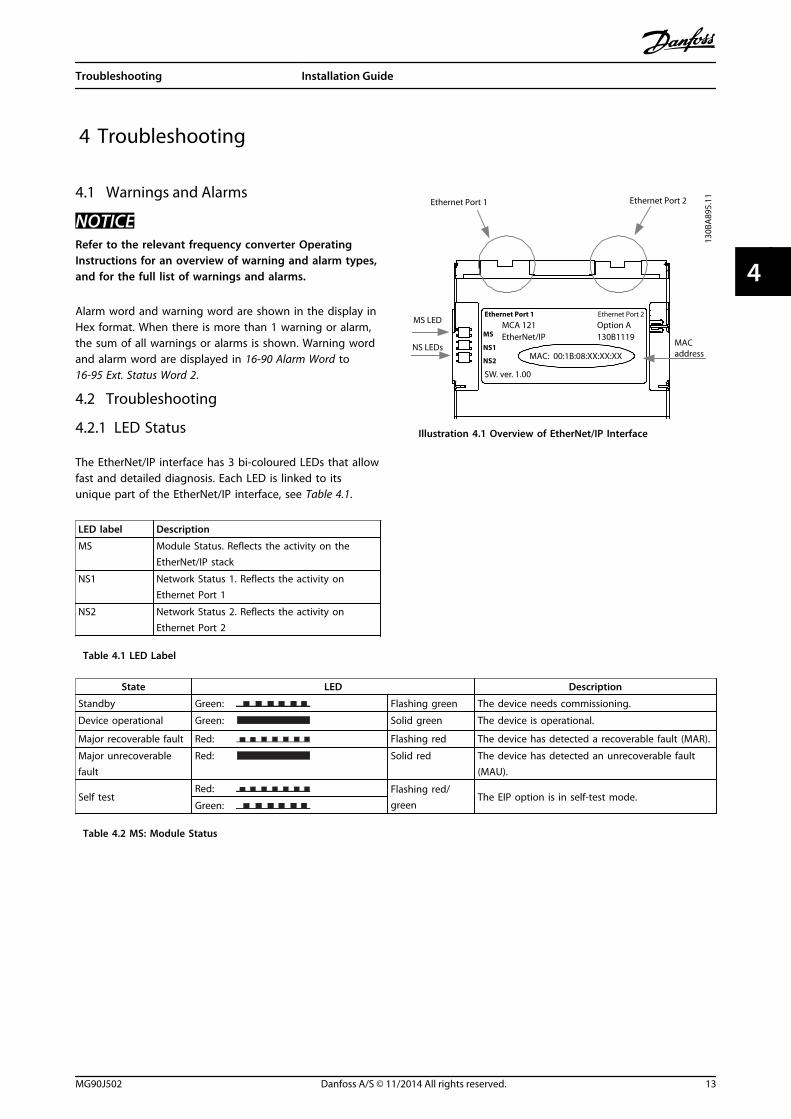
The EtherNet/IP interface has 3 bi-coloured LEDs that allowfast and detailed diagnosis. Each LED is linked to itsunique part of the EtherNet/IP interface, see Table 4.1.
LED label Description
MS Module Status. Reflects the activity on theEtherNet/IP stack
NS1 Network Status 1. Reflects the activity onEthernet Port 1
NS2 Network Status 2. Reflects the activity onEthernet Port 2
Table 4.1 LED Label
Ethernet Port 1
MS LED
NS LEDs
MCA 121 EtherNet/IP MS
NS2
NS1
Ethernet Port 1 Ethernet Port 2
MAC: 00:1B:08:XX:XX:XX
Option A130B1119
MAC address
Ethernet Port 2
SW. ver. 1.00
130B
A89
5.11
Illustration 4.1 Overview of EtherNet/IP Interface
State LED Description
Standby Green: Flashing green The device needs commissioning.
Device operational Green: Solid green The device is operational.
Major recoverable fault Red: Flashing red The device has detected a recoverable fault (MAR).
Major unrecoverablefault
Red: Solid red The device has detected an unrecoverable fault(MAU).
Self testRed: Flashing red/
greenThe EIP option is in self-test mode.
Green:
Table 4.2 MS: Module Status
Troubleshooting Installation Guide
MG90J502 Danfoss A/S © 11/2014 All rights reserved. 13
4 4
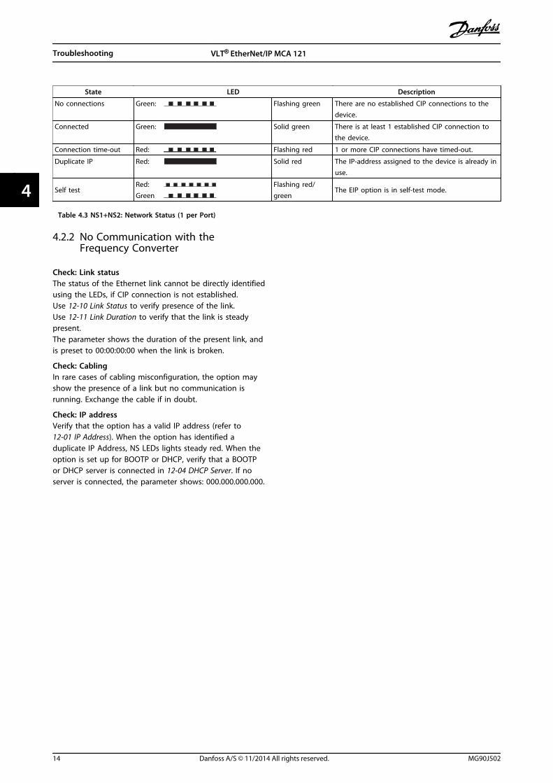
State LED Description
No connections Green: Flashing green There are no established CIP connections to thedevice.
Connected Green: Solid green There is at least 1 established CIP connection tothe device.
Connection time-out Red: Flashing red 1 or more CIP connections have timed-out.
Duplicate IP Red: Solid red The IP-address assigned to the device is already inuse.
Self testRed: Flashing red/
greenThe EIP option is in self-test mode.
Green
Table 4.3 NS1+NS2: Network Status (1 per Port)
4.2.2 No Communication with theFrequency Converter
Check: Link statusThe status of the Ethernet link cannot be directly identifiedusing the LEDs, if CIP connection is not established. Use 12-10 Link Status to verify presence of the link.Use 12-11 Link Duration to verify that the link is steadypresent.The parameter shows the duration of the present link, andis preset to 00:00:00:00 when the link is broken.
Check: CablingIn rare cases of cabling misconfiguration, the option mayshow the presence of a link but no communication isrunning. Exchange the cable if in doubt.
Check: IP addressVerify that the option has a valid IP address (refer to12-01 IP Address). When the option has identified aduplicate IP Address, NS LEDs lights steady red. When theoption is set up for BOOTP or DHCP, verify that a BOOTPor DHCP server is connected in 12-04 DHCP Server. If noserver is connected, the parameter shows: 000.000.000.000.
Troubleshooting VLT® EtherNet/IP MCA 121
14 Danfoss A/S © 11/2014 All rights reserved. MG90J502
44

Index
AAbbreviations........................................................................................... 3
Additional resources.............................................................................. 2
Alarms....................................................................................................... 13
Applying power.................................................................................... 12
Approvals................................................................................................... 2
CCable routing............................................................................................ 6
Cabling..................................................................................................... 14
Cabling requirements......................................................................... 10
Certifications............................................................................................. 2
Conventions.............................................................................................. 3
DDischarge time......................................................................................... 4
EElectrical interference............................................................................ 6
EMC interference..................................................................................... 6
EMC-compliant installation................................................................. 6
Ethernet................................................................................................... 14
Exploded view.......................................................................................... 8
GGrounding................................................................................................. 6
HHigh voltage............................................................................................. 4
IIntended use............................................................................................. 2
Items supplied.......................................................................................... 2
LLeakage current....................................................................................... 5
LED............................................................................................................... 3
Line topology........................................................................................... 7
Load sharing............................................................................................. 4
MMotor wiring............................................................................................. 6
Mounting................................................................................................... 8
NNetwork cabling.................................................................................... 12
QQualified personnel................................................................................ 4
RRedundancy manager switch............................................................. 8
Ring/redundant line topology........................................................... 7
SSafety........................................................................................................... 5
Screened cable.................................................................................. 6, 10
Star topology............................................................................................ 7
Symbols...................................................................................................... 3
TTopology.................................................................................................... 7
UUnintended start..................................................................................... 4
WWarnings.................................................................................................. 13
Wiring procedure................................................................................. 10
Index Installation Guide
MG90J502 Danfoss A/S © 11/2014 All rights reserved. 15

Danfoss can accept no responsibility for possible errors in catalogues, brochures and other printed material. Danfoss reserves the right to alter its products without notice. This also applies toproducts already on order provided that such alterations can be made without subsequential changes being necessary in specifications already agreed. All trademarks in this material are propertyof the respective companies. Danfoss and the Danfoss logotype are trademarks of Danfoss A/S. All rights reserved.
Danfoss A/SUlsnaes 1DK-6300 Graastenwww.danfoss.com/drives
*MG90J502*130R0430 MG90J502 11/2014