vista-20p series webcast. honeywell proprietary honeywell.com introduction this course will cover...
TRANSCRIPT

Vista-20P Series
WebCast

Honeywell Proprietary
Honeywell.com
Introduction
• This course will cover programming and features on the Vista-20P throughout, with several slides that explain and compare the Vista-20P with the Vista-10P and Vista-15P.

Honeywell Proprietary
Honeywell.com
Series Comparison
Vista-20P Vista-15P Vista-10PMax Zones 48 32 22
Standard wired zones 8 6 6Zone Doubling 15 0 0
Max Wired Expansion 40 22 0Max Wireless (5800) 40 26 16
Keyfob zones 16 8 8Programmable outputs 16 8 4
on-board Voltage triggers 2 2 2Zone Lists 12 10 9
Pager Support 4 2 1Event Log 100 50 32
User Codes 48 33 16AUI consoles 4 2 0

Honeywell Proprietary
Honeywell.com
Agenda
• Basic Panel Features• Mechanics of Programming• Programming Locations• *56 Zone Programming• *79 Output Device Mapping• *80 Defining Output Functions• Security Codes – Authority Levels & Special Features

Honeywell Proprietary
Honeywell.com
Features
• Unvacated auto stay • Cross zoning• Night arming• Carbon monoxide zone type• Dynamic zone type• Scheduling• Vent Zone• Automatic Periodic Test Command• SIA compliant

Honeywell Proprietary
Honeywell.com
ANSI/SIA CP-01-2000
A FALSE ALARM REDUCTION standard, calls for manufacturer’s to default control panels as follows:
•60 second exit delay•30 second entry delay plus 30 second dialer delay•Auto Stay arming enabled•Cancel verify option is enabled (displays on keypad)•Swinger suppression defaulted to 1 report per zone per armed period

Vista-20P Series Mechanics of Programming

Honeywell Proprietary
Honeywell.com
Mechanics of Programming
• Entering Program Mode - Use one of the following methods to enter Programming Mode:
1. Press both the [*] and [#] keys at the same time, within 50 seconds after power is applied to the Control.
2. After power-up, enter the Installer Code (4112) + 800
(If *98 was used to exit previously, method 1 above must be used to enter the program mode again)
Note: When connecting a console to a defaulted panel, the console must be set to address 16. This will be covered later.

Honeywell Proprietary
Honeywell.com
Defaulting
• To default the panel you will enter:– [ * ] + 9 + 7– Upon entering programming for the first time, it is recommended
that you default the panel.• To set the panel for first time communication with Compass
Downloading Software you will enter:– [ * ] + 9 + 6
• CSID = FFFFFFFF• Primary Subscriber Account Number = FFFF
Note: If your downloader requires a call back phone number, refer to field *94 in your programming form.

Honeywell Proprietary
Honeywell.com
Mechanics of Programming
* 20 Installer Code [4112]
Enter 4 digits, 0 – 9
To change the Installer’s Code you would enter Programming mode, then press *20, then the new code.
To view what is in field 20 you would enter #20, the panel will display the location contents one digit at a time.

Honeywell Proprietary
Honeywell.com
Mechanics of Programming
• Exiting Program Mode:
*98 prevents re-entry into the Programming modes using the Installer Code.
*99 allows re-entry into the Programming modes using Installer Code (4112) + 800
Note: If *98 is used to exit programming mode, the system must be powered down, AC and Battery, then press * & # simultaneously within 50 seconds of power up to re-enter programming.

Vista-20P Series
Programming Locations

Honeywell Proprietary
Honeywell.com
Entry/Exit Programming
*34 Exit Delay
*35 Entry Delay #1
*36 Entry Delay #2
[ 60,60 ]
00 - 96 = 0-96 Sec. 97 = 120 Sec.
Part. 1 Part. 2
Part. 1 Part. 2
[ 30,30 ]
00 - 96 = 0-96 Sec. 97 = 120 Sec. 98 = 180 Sec. 99 = 240 Sec.
Part. 1 Part. 2
[ 30,30 ]
Same entry choices as *35

Honeywell Proprietary
Honeywell.com
Communication Programming
*43 P1 Primary Account Number
*44 P1 Second Account Number
4 or 10 Digits [ FFFF ]
4 or 10 Digits [ FFFF ]
Enter up to 20 digits…
Enter up to 20 digits
…
*41 Primary Phone Number
*42 Second Phone Number

Honeywell Proprietary
Honeywell.com
Communication Programming
*45 P2 Primary Account Number
*46 P2 Second Account Number
*48 Report Format
4 or 10 Digits [ FFFF ]
4 or 10 Digits [ FFFF ]
[ 7,7 ]
0 = 3+1, 4+1 Ademco L/S Stand. 6 = 4+2 Ademco Express1 = 3+1, 4+1 Radionics Stand. 7 = 4-digit Ademco Contact ID2 = 4+2 Ademco L/S Stand. 8 = 3+1, 4+1 Ademco L/S Stand.3 = 4+2 Radionics Stand. 9 = 3+1, 4+1 Radionics Expanded5 = 10-Digit Ademco Contact ID
Prim. Sec.
Honeywell Proprietary
Honeywell.com
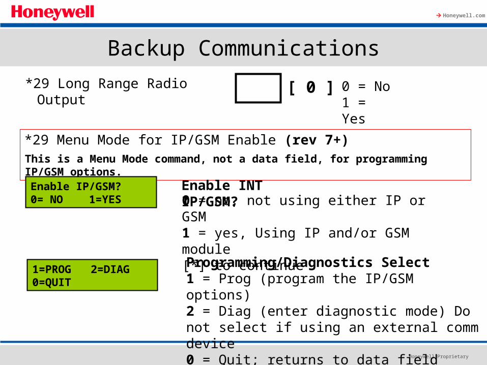
This is a Menu Mode command, not a data field, for programming IP/GSM options.
Backup Communications
*29 Menu Mode for IP/GSM Enable (rev 7+)
Enable IP/GSM?0= NO 1=YES
Enable INT IP/GSM?0 = no, not using either IP or GSM1 = yes, Using IP and/or GSM module[*] to continue
1=PROG 2=DIAG0=QUIT
Programming/Diagnostics Select1 = Prog (program the IP/GSM options)2 = Diag (enter diagnostic mode) Do not select if using an external comm device0 = Quit; returns to data field programming mode
*29 Long Range Radio Output [ 0 ] 0 = No1 = Yes

Honeywell Proprietary
Honeywell.com
Internal Device Programming Prompts[ ] = scroll the options of a particular prompt∗[#] = accept the entry and move to the next prompt[A] = backspace or shift-[A] for escape[B] = scroll to next prompt or shift-[B] scroll to previous prompt[C] = answer No or shift-[C] answer Yes to prompt[D] = shift key
*29 Menu Mode Keypad Functions

Honeywell Proprietary
Honeywell.com
Backup Communications
*54 Dynamic Signaling Delay
*55 Dynamic Signaling Priority
0 = No delay (Both signals sent)1-15 = delay times in 15 sec. increments1 = 15 Sec. 2 = 30 Sec. Etc.Note: if *55 is set to “0”, use min. 30 sec to avoid redundant IP report.
[ 0 ]
0 = Primary Dialer first1 = IP/GSM module first
[ 0 ]

Honeywell Proprietary
Honeywell.com
System Setup
*84 Auto Stay Arm
*85 Cross Zone Timer
*93 Reports in Armed Period Per Zone
[1] 0=no, 1=partition 1 only2=partition 2 only, 3=both partitions
[0] 0=15 sec.
(see program sheet for complete list of options)
(Assign cross zones on zone list 4, with *81 Menu mode)
If enabled, the system will automatically change AWAY mode to STAY mode if the entry/exit door is not opened and closed within the exit delay time after the user arms in AWAY mode from a wired keypad.
[1] 0=Unlimited Reports 1=1 report per 2=2 reports per

Honeywell Proprietary
Honeywell.com
Pager Information
*160 Pager 1 Phone No.
….
….Enter up to 20 digits
Enter up to 16 digits
*161 Pager 1 Characters
The character could be composed of: • PIN number• Subscriber account number• * (enter # + 11 to send *)• # (enter # + 12 to send #)• Pause (enter # + 13 to allow a 2-second pause)
7-digit status code: XXX-YYYY
XXX = 3-digit event code:911 = Alarm811 = Trouble101 = Opening (disarm)102 = Closing (arm AWAY
YYYY = 4-digit user or zone numberThe first digit indicates the partition, followed by the 3-digit user or zone number. 0 = system, 1 = part 1
2 = part 2, 3 = part 3

Honeywell Proprietary
Honeywell.com
Pager Options
*162 Pager 1 Reporting Options
Part. 1 Part. 2 Common
0 = no report sent 1 = open/closes all users 4 = All alarms and troubles12 = Alarms/troubles for zones entered in zone list 913 = Alarms/troubles for zones entered in zone list 9 and open/close for all users
Pagers 2-4 are set up the same way in Locations *163 -*171
[ 0,0,0 ]

Honeywell Proprietary
Honeywell.com
Pager Options
*172 Pager Delay Option for Alarms [3]
0 = none1 = 1 minute2 = 2 minutes3 = 3 minutes
This delay is for ALL pagers in the system.

Honeywell Proprietary
Honeywell.com
Configurable Zone Type Programming
See programming sheet for complete List of options. 1 2 3 4 5 6 7 8 9 10
*182 Configurable Zone Type 90
Enter the desired 3-digit Contact ID report codes for alarms and troubles occurring on zones assigned to this zone type.
90 Alarm ID XXXTrouble ID:XXX
*183 Zone Type 90 Report Codes
See programming sheet for complete List of options. 1 2 3 4 5 6 7 8 9 10
*184 Configurable Zone Type 91
Enter the desired 3-digit Contact ID report codes for alarms and troubles occurring on zones assigned to this zone type.
91 Alarm ID XXXTrouble ID:XXX
*185 Zone Type 91 Report Codes

Honeywell Proprietary
Honeywell.com
Advanced User Interface Programming
*189 Symphony (AUI) enable
Enter each AUI’s Home partition.0 = disabled1 = partition 1; 2 = partition 23 = partition 3 (common)
[1] [1] [0] [0]AUI 1 AUI 2 AUI 5 AUI 6
Note: an external power supply may be required when using AUI consoles.

Honeywell Proprietary
Honeywell.com
Keypad Options
*190 Keypad 2 Address 17
*191 – *196 Are Identical for addresses 18 – 23 respectively.
Partition/Enable Sound
[0] [0]
0 = keypad disabled;1-3 = part.no. (3=common)
0 = no suppression1 = suppress arm/disarm and E/E beeps2 = suppress chime beeps only3 = suppress arm/disarm, E/E, and chime beeps
NOTE: Options for keypad address 16 are set by the factory and cannot be changed. Each keypad must be assigned a unique address.

Honeywell Proprietary
Honeywell.com
Keypad Options
*197 Exit Time Display Interval
*198 Display Partition Number (for Alpha Display Keypads)
*199 ECP Fail Display
[0]0 = no display1-5 = seconds between display refresh
[0]0= no; 1=yes(partition number appears on Alpha Display)
[0]0 = 3-digit display (“1” + device address)1 = 2-digit fixed-display as “91”

Vista-20P Series
ECP Addressing
Honeywell Proprietary
Honeywell.com
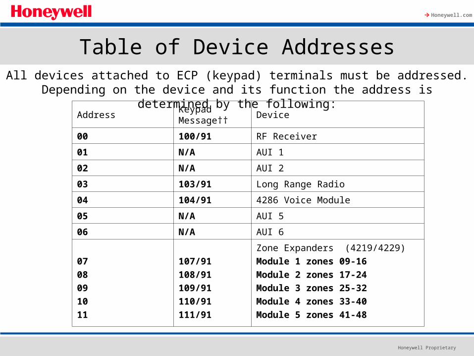
Table of Device AddressesAll devices attached to ECP (keypad) terminals must be addressed.
Depending on the device and its function the address is determined by the following:
AddressKeypad Message††
Device
00 100/91 RF Receiver
01 N/A AUI 1
02 N/A AUI 2
03 103/91 Long Range Radio
04 104/91 4286 Voice Module
05 N/A AUI 5
06 N/A AUI 6
07
08
09
10
11
107/91
108/91
109/91
110/91
111/91
Zone Expanders (4219/4229)
Module 1 zones 09-16
Module 2 zones 17-24
Module 3 zones 25-32
Module 4 zones 33-40
Module 5 zones 41-48

Honeywell Proprietary
Honeywell.com
Table of Device Addresses
Address Keypad Message†† Device
12
13
14
15
112/91
113/91
114/91
115/91
Relay Modules (4204)
Module 1
Module 2
Module 3
Module 4
16-23 N/A
Keypads
Keypad 1 – 8
28 N/A 5800TM module
†† Addressable devices are identified by “1” plus the device address when reporting. Enter a report code for zone 91 to enable addressable device reporting (default = reports enabled). See field *199, mentioned earlier, for ECP Fail Display options.

Vista-20P Series
Zone Programming*56 Menu Mode

Honeywell Proprietary
Honeywell.com
*56 Zone Programming Mode
SET TO CONFIRM?0= NO 1=YES 0
Confirm?
Zn ZT P RC In: L10 00 1 10 RF 1
Enter Zone Number01-99 = zone number00 = quit
[*] to continueNot all numbers Available.
Enter Zn Num.(00 = Quit) 10
Summary Screen[*] to continue
IN: L = Wireless, RF = SupervisionIN: AD = Expansion, AW = Aux wiredHW: RT = Hard Wire, EL = loop type
Zn ZT P RC In: AD10 00 1 10 AW: 07
Zn ZT P RC HW: RT02 00 1 10 EL 1
Or
Or
0 = no1= yes

Honeywell Proprietary
Honeywell.com
*56 Zone Programming Mode
10 Zone TypePerimeter 03
Zone Type (ZT)00 = Not Used01 = Entry/Exit #102 = Entry/Exit #203 = Perimeter04 = Interior Follower05 = Day/Night06 = 24-Hr Silent07 = 24-Hr Audible08 = 24-Hr Aux09 = Fire10 = Interior w/Delay
12 = Monitor Zone14 = Carbon Monoxide16 = Fire w/Verify20 = Arm-Stay*21 = Arm-Away*22 = Disarm*23 = No Alarm Response24 = Silent Burglary77 = Keyswitch81 = AAV Mon. Zone90-91 = Configurable
* 5800 button-type transmitters only.

Honeywell Proprietary
Honeywell.com
*56 Zone Programming Mode
10 Partition 1
Partition No. (P)
02 Hardwire TypeEOL 0
Report Code (RC)01-09, 10 for 0, 11 for B, 12 for C, 13 for D, 14 for E, 15 for F. 00 to DisableExamples: 01 00 = report code 10 13 15 = report code DF
1-3 = partition (3=Common)[*] to continue
10 Report Code1st 01 2nd 00 10
Hardwire Type0=EOL; 1=NC; 2=NO; 3=zone doubling (ZD); 4=double-balanced (DB). This prompt appears only for zone numbers 02-08. [*] to continue

Honeywell Proprietary
Honeywell.com
*56 Zone Programming Mode
02 Response Time 1
Response Time (RT)
10 Input S/N: LA XXX-XXXX 1
Input Device type (In)2 = AW (Aux wired zone)3 = RF (supervised RF transmitter)4 = UR (unsupervised RF transmitter)5 = Button type RF transmitter (unsupervised)
0 = 10mSec; 1 = 350mSec; 2 = 700mSec; 3=1.2 seconds[*] to continueOnly for zones 01-08, zone 02 shown
10 Input TypeRF Trans 3
Serial number Entry and Loop Number EntryUsed only when enrolling wireless transmitters.a. Transmit two open/close sequences.b. Manually enter the 7-digit serial number.c. Press key [C] to copy the serial number previously
enrolled.[*] to continue

Honeywell Proprietary
Honeywell.com
*56 Zone Programming ModeLoop Number Change10 Input S/N: L
A 022-4064 ?
Enroll SummaryIf the serial/loop number combination is not a duplicate in the system, a display showing the serial number and loop number entry will appear.[*] to continue
Enter the loop number.To delete enter 0 in the loop number.[*] to continue
10 Input S/N: LA 022-4064 1
10 XMIT TO CONFIRMPRESS * TO SKIP
ConfirmNote: This prompt will only appear if the firstprompt after entering *56 was answered “YES”[*] to continue

Honeywell Proprietary
Honeywell.com
*56 Zone Programming Mode
Not Confirmed[*] to continueIf the serial number transmitted does not match the serial number entered this prompt will appear.
Entd A022-4063Rcvd A022-4064
Zn ZT P RC In: L10 03 1 10 RF 1
Summary Screen[*] to continue

Vista-20P Series
Output Programming

Honeywell Proprietary
Honeywell.com
Output Device Option
*177 Device Duration 1,2
(used in *80 menu mode-Device Actions 5/6)
[0] [0]
1 2
0 = 15 secs1 = 30 secs2 = 45 secs3 = 60 secs4 = 90 secs5 = 2 min6 = 2-1/2 min7 = 3 min
8 = 4 min 9 = 5 min# = 10 = 6 min# + 11 = 7 min# +12 = 8 min# + 13 = 10 min# + 14 = 12 min# + 15 = 15 min

Vista-20P Series Output Device Mapping*79 Menu Mode

Honeywell Proprietary
Honeywell.com
*79 Menu Mode
*79 Mode is used to identify available outputs that the panel can use.
These outputs are actually programmed to activate and release in
*80 defining output functions.

Honeywell Proprietary
Honeywell.com
*79 Menu Mode
ENTER OUTPUT NO.00 = QUIT xx
Device Output Number01-18 relays/X-10;00 = Quit[*] to continue
XX OUTPUT TYPEDELETE 0
Output Type - This prompt appears if selecting outputs 01-16.0 = delete1 = relay on 4204/4229 module2 = Powerline / X-10[*] to continue
If X-10 is selected, we will use “A” promptIf relay is selected, we will use “B” prompt
This is the reference relay number as used in the system. Relays and X-10 devices are numbered 01-16. The on-board triggers are numbered 17 and 18.
Honeywell Proprietary
Honeywell.com
*79 Menu Mode
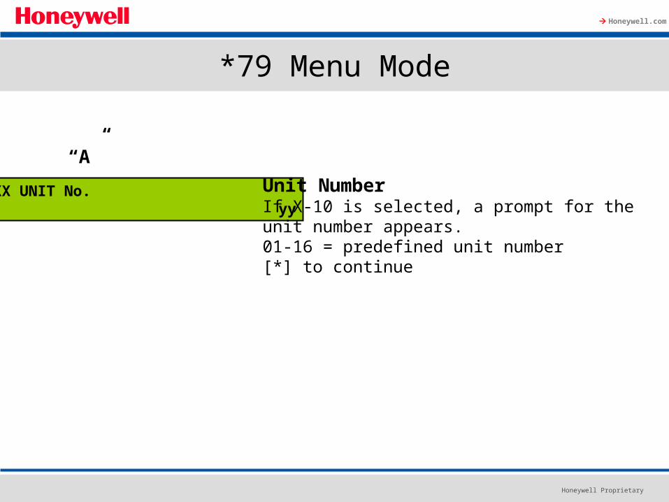
XX UNIT No. yy
Unit NumberIf X-10 is selected, a prompt for the unit number appears.01-16 = predefined unit number[*] to continue
“A”

Honeywell Proprietary
Honeywell.com
*79 Menu Mode
XX MODULE ADDR07-15 yy
Module Address07-15 = predefined address[*] to continue
“B” Module Address
Address Module
07 1st 4229 (with zones 09-16)
08 2nd 4229 (with zones 17-24)
09 3rd 4229 (with zones 25-32)
10 4th 4229 (with zones 33-40)
11 5th 4229 (with zones 41-48)
12 1st 4204
13 2nd 4204
14 3rd 4204
15 4th 4204
Honeywell Proprietary
Honeywell.com
*79 Menu Mode
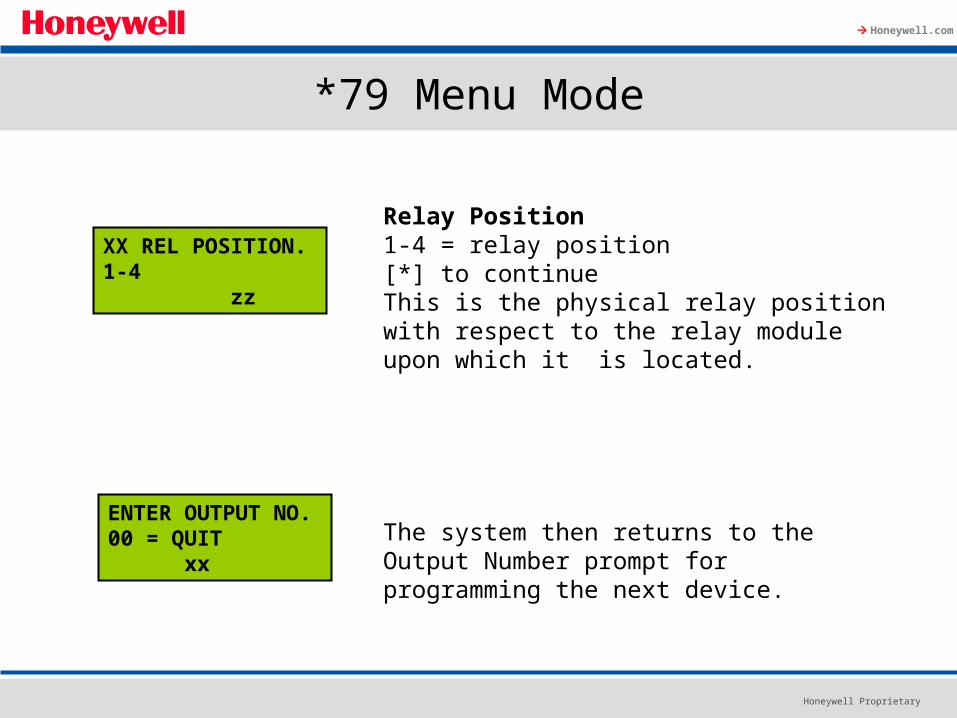
XX REL POSITION.1-4 zz
Relay Position1-4 = relay position[*] to continueThis is the physical relay position with respect to the relay module upon which it is located.
The system then returns to the Output Number prompt for programming the next device.
ENTER OUTPUT NO.00 = QUIT xx

Honeywell Proprietary
Honeywell.com
*79 Menu Mode
17 OUT NORM LOW0= NO 1=YES 0
Output Normally Low0=no (standard default)1=yes[*] to continue
This prompt appears only for triggers 17 & 18.Selecting 0 (no) sets the output level normally high(open).Selecting 1 (yes) set the output level normally low(ground).Output trigger 17 (100mA max.) can be used for resetting 4-wire smoke detectors (up to 2 smokes) by connecting it to the negative power terminal of the smoke detector.

Vista-20P Series
Defining Output Functions*80 Menu Mode

Honeywell Proprietary
Honeywell.com
*80 Menu Mode
In *80, we program relays or X-10 devices, previously defined in *79 output device mapping, to activate and deactivate.
The Vista-20P allows 48 output functions to be programmed.The Vista-15P allows 24 output functions to be programmed.The Vista-10P allows 12 output functions to be programmed.Each output function determines only one action.
For example: To turn a relay on and off requires two output functions.

Honeywell Proprietary
Honeywell.com
*80 Menu Mode
Output Funct. #(00 = Quit) 01
Output Function No.01 – 48 output function numberEnter the output function number to be defined(or 00 to exit).[*] to continue
01 A E P Trig?00 0 0 - ZL=1
Summary ScreenA= Output Action; E= Triggering event;P= Partition; Trig = Trigger type[*] to continue
Note: A question mark in the summary screen indicates that the device number shown has not been mapped. Use *79 Menu mode to map the device.

Honeywell Proprietary
Honeywell.com
*80 Menu Mode
Activated By0 = delete (delete the output function and any previous programming; see prompt below1 = zone list (go to “A” prompt)2 = zone type (go to “B” prompt)3 = zone number (go to “C” prompt)[*] to continue
Delete?0 = NO, 1 = YES Press 1 to delete this output definition.
01 Activated by:Delete 0

Honeywell Proprietary
Honeywell.com
01 Zn List
1
Zone List1 – 8 zone list[*] to continue
“A”
Enter EventAlarm 1
0 = restore; 1 = alarm;2 = fault; 3 = trouble
NOTE: For alarm, fault, and trouble an event on ANYZone in the list activates the output, but ALL zones inthe list must be restored before the output is restored.Press [*] to continue to the “Output Action” prompt.
*80 Menu Mode
01 Activated by:Zone List 1

Honeywell Proprietary
Honeywell.com
*80 Menu Mode
01 Enter Zn typePerimeter 03
Zone TypeEnter the desired zone type:There are a wide variety of zone types and system operations available.[*] to continue
“B”
01 PartitionAny partition
Enter the partition in which this zone type will occur.
0 = any partition; 1 = partition 1;2 = partition 2; 3 = commonPress [*] to continue to the “Output Action” prompt.
01 Activated by:Zone Type 2

Honeywell Proprietary
Honeywell.com
*80 Menu Mode
“C”
01 Enter Zn No. 12
Zone NumberEnter the zone number desiredPress [*] to continue.
01 Enter EventRestore 0
Enter the zone event that will activate this output.0 = restore; 1 = alarm/fault/trouble
Press [*] to continue to the “Output Action prompt
01 Activated by:Zone Number 3

Honeywell Proprietary
Honeywell.com
*80 Menu Mode
01 Output ActionClose for 2 sec
Output Action 0 – 60 = off 4 = Change Device State1 = Close for 2 seconds 5 = Duration 1 (see data field *177)2 = Close and Stay Closed 6 = Duration 2 (see data field *177)3 = Continuous Pulse on & off (1 sec ON, 1 sec OFF)
Enter Output No.R02 02
Output Number 01 – 16 = as defined in *7917 – 18 = on-board triggersEnter the device output number (as defined in *79) you want associated with this output function. Press [*] to continue
02 A E P TRIGR02 1 1 3 ZL=1
Summary ScreenPress [*] to continue

Vista-20P Series
Test Report Setup

Honeywell Proprietary
Honeywell.com
Automatic Periodic Test Report
The system can be set to automatically send test reports (automatically enables report code in field *64; Contact ID code 602) at specified intervals.
The frequency of the report can be set in Scheduling mode (event 11) or by the following key commands:
Installer code + [#] + 0 + 0 = test report sent every 24 hoursInstaller code + [#] + 0 + 1 = test report sent once per weekInstaller code + [#] + 0 + 2 = test report sent every 28 days
Each mode sets schedule 32, to the stated repeat option; the first test report is sent 12 hours after command.
To ensure that test reports are sent at the times expected, set the Real-Time Clock to the proper time before entering the test report schedule command.

Honeywell Proprietary
Honeywell.com
Setting the Real Time Clock
Enter [4-digit Installer or Master code] + # + 63
•Press the [*] key to change the Date/Time settings. The blinking cursor appears on the first digit of the hour.•Enter the time (hour, then minute). After each entry the cursor moves to the right.•Press any odd-digit for PM, or any even-digit for AM.•Enter the 2-digit year, 2-digit month, and the 2-digit day in sequence. The day of the week is automatically calculated and displayed based on the date entered.•Press the [#] key to move the cursor to the left to make any changes that may be needed.•When entry is complete press the [*] key until the cursor is at the far right position.•To accept all of the clock information, press the [*] key again.
TIME/DATE SAT12:00AM 01/01/00
TIME/DATE SAT12:00A 2000/01/01

Vista-20P Series
Security Codes

Honeywell Proprietary
Honeywell.com
Security Codes
Vista-20P supports up to 48 user codes which can be assigned one of 5 authority levels.
Vista-15P supports up to 33 user codes which can be assigned one of 4 authority levels.
Vista-10P supports up to 16 user codes which can be assigned one of 4 authority levels.
Honeywell Proprietary
Honeywell.com
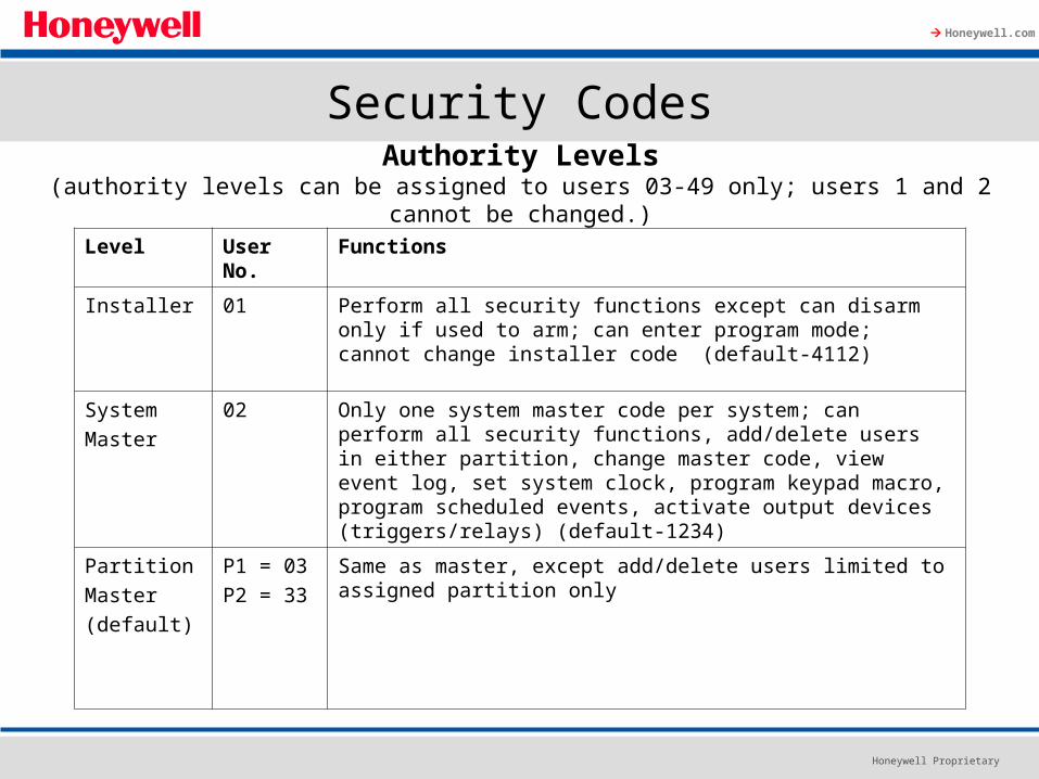
Security Codes
Level User No. Functions
Installer 01 Perform all security functions except can disarm only if used to arm; can enter program mode; cannot change installer code (default-4112)
System
Master
02 Only one system master code per system; can perform all security functions, add/delete users in either partition, change master code, view event log, set system clock, program keypad macro, program scheduled events, activate output devices (triggers/relays) (default-1234)
Partition
Master
(default)
P1 = 03
P2 = 33
Same as master, except add/delete users limited to assigned partition only
Authority Levels(authority levels can be assigned to users 03-49 only; users 1 and 2 cannot be changed.)

Honeywell Proprietary
Honeywell.com
Security Codes
Level User No. Functions
0-User 03-49 Perform security functions (arm, disarm,etc) only; cannot add/delete users, view event log, set system clock or program scheduled events.
1-Arm only 03-49 Arm system only
2- Guest 03-49 Can disarm the system only if it was used to arm the system
3-Duress 03-49 Performs security functions, but also silently sends a duress message to the central station; reports as zone 92
4-Partition
Master
03-49 Used to assign other user numbers as partition masters
Not used for the Vista-15P and Vista-20P
Authority Levels(authority levels can be assigned to users 03-49 only; users 1 and 2 cannot be changed.)

Honeywell Proprietary
Honeywell.com
Security Codes
Adding a User Code: Master code + [8] + 2-digit user no. + user’s codeDeleting a User Code: Master code + [8] + 2-digit user no. + [#] [0]Assigning Attributes: Master code + [8] + 2-digit user no. + [#] [attribute no] + value
Attributes: Values
1=Authority Level 0-4 (see Authority Level table)2=Access Group 0-8 (0= not assigned to a group)3=Active Partition 1,2,3 (common) for this user;4=RF Zone No. Assigns user number to button type
zone for arm/disarm5=Open/Close paging 1 for yes; 0 for no
Honeywell Proprietary
Honeywell.com
Review
• What is the maximum number of zones?• Do the keyfob zones count in the above number?• How many programmable outputs does each panel offer?• Do all ECP devices (keypads, expanders, etc.) need to have a
unique address?• Can we program a relay to activate in *79 output device
mapping?

http://www.security.honeywell.com/hsc/
and click on MyWebTech
User name: honeywell
Password: support99
Honeywell Security support e-mail: [email protected]