vision for robotic object manipulation in domestic …hic/hic-papers/danik05-ras.pdf · robotics...
TRANSCRIPT
Robotics and Autonomous Systems 52 (2005) 85–100
Vision for robotic object manipulation in domestic settings
Danica Kragic∗, Marten Bjorkman, Henrik I. Christensen, Jan-Olof Eklundh
Computer Vision and Active Perception Lab, Centre for Autonomous Systems, Royal Institute of Technology, Stockholm, Sweden
Received 5 March 2005; accepted 21 March 2005Available online 9 June 2005
Abstract
In this paper, we present a vision system for robotic object manipulation tasks in natural, domestic environments. Givencomplex fetch-and-carry robot tasks, the issues related to the wholedetect-approach-grasploop are considered. Our visionsystem integrates a number of algorithms using monocular and binocular cues to achieve robustness in realistic settings. Thecues are considered and used in connection to both foveal and peripheral vision to provide depth information, segmentation of theobject(s) of interest, object recognition, tracking and pose estimation. One important property of the system is that the step fromobject recognition to pose estimation is completely automatic combining both appearance and geometric models. Experimentalevaluation is performed in a realistic indoor environment with occlusions, clutter, changing lighting and background conditions.© 2005 Elsevier B.V. All rights reserved.
Keywords:Cognitive systems; Object recognition; Service robots; Object manipulation
1
tipwmfbp
c(
s onper-ourenf ev-hingirest—ioning
t the
ionis
els
0d
. Introduction
One of the key components of a robotic systemhat operates in a dynamic, unstructured environments robust perception. Our current research considers theroblem of mobile manipulation in domestic settingshere, in order for the robot to be able to detect andanipulate objects in the environment, robust visual
eedback is of key importance. Humans use visual feed-ack extensively toplanandexecuteactions. However,lanning and execution is not a well-defined one-way
∗ Corresponding author. Tel.: +46 87906729; fax: +46 87230302.E-mail addresses:[email protected] (D. Kragic);
[email protected] (M. Bjorkman); [email protected]. Christensen); [email protected] (J.-O. Eklundh).
stream: how we plan and execute actions dependwhat we already know about the environment we oate in, what we are about to do, and what we thinkactions will result in. Complex coordination betwethe eye and the hand is used during execution oeryday activities such as pointing, grasping, reacor catching. Each of these activities or actions requattention to different attributes in the environmenwhile pointing requires only an approximate locatof the object in the visual field, a reaching or graspmovement requires more exact information abouobject’s pose.
In robotics, the use of visual feedback for motcoordination of a robotic arm or platform motiontermedvisual servoing, Hutchinson et al.[1]. In gen-eral, visual information is important at different lev
921-8890/$ – see front matter © 2005 Elsevier B.V. All rights reserved.oi:10.1016/j.robot.2005.03.011

86 D. Kragic et al. / Robotics and Autonomous Systems 52 (2005) 85–100
of complexity: from scene segmentation to object’spose estimation. Hence, given a complex fetch-and-carry type of task, issues related to the wholedetect-approach-grasploop have to be considered. Most vi-sual servoing systems, however, deal only with theap-proachstep and disregard issues such asdetectingtheobject of interest in the scene or retrieving its threedimensional (3D) structure in order to perform grasp-ing. A so calledteach-by-showingapproach is typi-cally used where the desired camera placement withrespect to the object is well defined and known beforehand.
Our goal is the development of an architecture thatintegrates different modules where each module en-capsulates a number of visual algorithms responsi-ble for a particular task such as recognition or track-ing. Our system is heavily based on theactive vi-sionparadigm, Ballard[2] where, instead of passivelyobserving the world, viewing conditions are activelychanged so that the best results are obtained given atask at hand.
In our previous work, Bjorkman and Kragic[3] wehave presented a system that consists of two pairs ofstereo cameras: a peripheral camera set and a fovealone. Recognition and pose estimation are performedusing either one of these, depending on the size anddistance to the object of interest. From segmentationbased on binocular disparities, objects of interest arefound using the peripheral camera set, which then trig-gers the system to perform a saccade, moving the ob-j us ac es-o m eta ands en-t larc r, wef ectt tod
a to ec-t ionw b-j gu rasp-i is
presented in Section8 and final conclusion given inSection9.
2. Problem definition
In general, vision based techniques employed in vi-sual servoing and object manipulation depend on:• Camera placement: Most visual servoing systems
today useeye-in-handcameras and deal mainly withtheapproachobject step in ateach-by-showingman-ner, Malis et al.[5]. In our approach, we consider acombination of a stand-alone stereo and an eye-in-hand camera systems, Kragic and Christensen[6].
• Number of cameras: In order to extract metricinformation, e.g. sizes and distances, about objectsobserved by the robot, we will show how we canbenefit from binocular information. The reason forusing multiple cameras in our system is the fact thatit simplifies the problem of segmenting the imagedata into different regions representing objects in a3D scene. This is often referred to asfigure-groundsegmentation. In cluttered environments and com-plex backgrounds, figure-ground segmentation isparticularly important and difficult to perform andcommonly the reason for experiments being per-formed in rather sparse, simplified environments.In our work, multiple cameras are used for scenesegmentation while a single camera is used forvisual servoing, object tracking and recognition.
• singpe-
orknity,n-eralbject
I skss icku k orc ayb neds ernalrj n inF botl e and
ect into the center of foveal cameras achieving thombination of a large field of view and high image rlution. Compared to one of the recent systems, Kil. [4], our system uses both hard (detailed models)oft modeling (approximate shape) for object segmation. In addition, choice of binocular or monocuues is used depending on the task. In this papeormalize the use of the existing system with respo Fig. 1—how to utilize the system with respectifferent types of robotic manipulation tasks.
This paper is organized as follows. In Section2,problem definition is given. In Section3, a shor
verview of the current system is given and in Sion 4 hypotheses generation is presented. In Sect5e deal with the problem of manipulating known o
ects and in Section6with the problem of manipulatinnknown objects. Some issues related to object g
ng are given in Section7. Experimental evaluation
Camera type: Here we consider systems uzooming cameras or combinations of foveal andripheral ones. With respect to these, very little whas been reported in visual servoing commuBenhimane and Malis[7]. In this paper, we demostrate how a combination of foveal and periphcameras can be used for scene segmentation, orecognition and pose estimation.
n our current system, the robot may be given tauch as “Robot, bring me the raisins” or “Robot, pp this”. Depending on the prior information, i.e. tasontext information, different solution strategies me chosen. The first task of the above is well defiince it assumes that the robot already has the intepresentation of the object, e.g. theidentityof the ob-ect is known. An example of such a task is showig. 2: after being given a spoken command, the ro
ocates the object, approaches it, estimates its pos

D. Kragic et al. / Robotics and Autonomous Systems 52 (2005) 85–100 87
Fig. 1. Robotic manipulation scenarios.
finally performs grasping. More details related to thisapproach are given in Section5. For the second task, thespoken command is commonly followed by a pointinggesture—here, the robot does not know theidentityofthe object, but it knows its approximatelocation. Theapproach considered in this work is presented in Sec-tion 6. Fig. 1shows different scenarios with respect toprior knowledge of objectidentityand location, withthe above examples shaded. A different set of underly-
Fig. 2. Detect-approach-grasp example.
c Tech
ing visual strategies is required for each of these sce-narios. We have considered these two scenarios sincethey are the most representative examples for roboticfetch-and-carry tasks.
2.1. Experimental platform
The experimental platform is a Nomadic Technolo-gies XR4000, equipped with a Puma 560 arm for ma-nipulation (seeFig. 3). The robot has sonar sensors, aSICK laser scanner, a wrist mounted force/torque sen-sor (JR3), and a color CCD camera mounted on theBarrett Hand gripper. The palm of the Barrett hand iscovered by a VersaPad touch sensor and, on each fin-ger, there are three Android sensors. On the robot’sshoulder, there is a binocular stereo-head. This sys-tem, known as Yorick, has four mechanical degrees offreedom; neck pan and tilt, and pan for each camera inrelation to the neck. The head is equipped with a pair of
Fig. 3. (Left) Experimental platform Nomadi
nologies XR4000, and (Right) Yorick stereo-head.
88 D. Kragic et al. / Robotics and Autonomous Systems 52 (2005) 85–100
Sony XC999 cameras, with focal length of 6 mm. Ad-ditional pair of Sony XC999 cameras with focal lengthof 12 mm is placed directly on the robot base.
For some of the experimental results that will be pre-sented further on, a stand-alone binocular stereo-headsystem shown inFig. 3 was used. Here, the head isequipped with two pairs of Sony XC999 cameras, withfocal lengths 28 and 6 mm, respectively. The motiva-tion for this combination of cameras will be explainedrelated to the examples.
3. The system
Fig. 4 shows a schematic overview of the basicbuilding blocks of the system. These blocks do not nec-essarily correspond to the actual software components,but are shown in order to illustrate the flow of informa-tion through the system. For example, the visual frontend consists of several components, some of which arerunning in parallel and others hierarchically. For ex-ample, color and stereo information are extracted inparallel, while epipolar geometry has to be computedprior to disparities. On the other hand, action genera-tion, such as initiating 2D or 3D tracking, is distributedand performed across multiple components.
The most important building blocks can be summa-rized as follows:• The Visual Front-End is responsible for the ex-
traction of visual information needed for figure-
ground segmentation and other higher level proce-sses.
• Hypotheses Generation produces a number of hy-potheses about the objects in the scene that may berelevant to the task at hand. The computations aremoved from being distributed across the whole im-age to particular regions of activation.
• Recognition is performed on selected regions, usingeither corner features or color histograms, to deter-mine the relevancy of observed objects.
• Action Generation triggers actions, such as visualtracking and pose estimation, depending on the out-come of the recognition and current task specifica-tion.
Due to the complexity of the software system, itwas partitioned into a number of smaller modulesthat communicate through a framework built on ainterprocess communication standard called CORBA(Common Object Request Broker Architecture),Vinoski [8]. The current version of the system consistsof about ten such modules, each running at a differentframe rate. The lowest level frame grabbing moduleworks at a frequency of 25 Hz, while the recognitionmodule is activated only upon request. In order toconsume processing power, modules are shut downtemporarily when not been accessed by any othermodule within a time frame of 10 s.
With limited resources in terms of memory stor-age and computational power, biological and robotic
ding bl
Fig. 4. Basic buil ocks of the system.
D. Kragic et al. / Robotics and Autonomous Systems 52 (2005) 85–100 89
systems need to find an acceptable balance betweenthe width of the visual field and its resolution. Other-wise, the amount of visual data will be too large for thesystem to efficiently handle. Unfortunately, this bal-ance depends on the tasks the systems have to perform.An animal that has to stay alert in order to detect an ap-proaching predator, would prefer a wide field of view.The opposite is true if the same animal acts as a preda-tor itself. Similarly, a robotic system benefits from awide field of view, in order not to collide with obsta-cles while navigating through a cluttered environment.A manipulation task on the other hand, requires a highresolution in order grasp and manipulate objects. Thatis, to find objects in the scene a wide field of view ispreferable, but recognizing and manipulating the sameobjects require a high resolution.
On a binocular head, Bjorkman and Kragic[3] weovercame this problem by using a combination of twopairs of cameras, a peripheral set for attention and afoveated one for recognition and pose estimation. Inorder to facilitate transfers of object hypotheses fromone pair to the other, and replicate the nature of the hu-man visual system, the pairs were placed next to eachothers. The camera system on the robot is different inthat the two pairs are widely separated and placed onan autonomously moving platform, seeFig. 3: a stereohead on a shoulder and another pair on the base. Thesearch pair is located on-top of the robot overlookingthe scene and the manipulation pair is at waist height,such that the gripper will not occlude an object while iti th-e turesa latedp riph-e f thef
si-b erass s be-t r off tures eryd ng.I ovet byt tionp telyk re-
lation to the base. Hypotheses are found by the searchpair, the 3D positions are derived using triangulationand finally projected onto the image planes of the ma-nipulation pair. For the 3D position to be accuratelyestimated, the search pair is calibrated on-line, simi-larly to the original version of the system, Bjorkmanand Eklundh[9]. The precision in depth ranges fromabout a decimeter to half a meter depending on theobserved distance.
3.1. Stereo system modeling—epipolar geometry
With a binocular set of cameras, differences inposition between projections of 3D points onto theleft and right image planes (disparities) can be usedto perform figure-ground segmentation and retrievethe information about three-dimensional structureof the scene. If the relative orientation and positionbetween cameras is known, it is possible to relatethese disparities to actual metric distances. One of thecommonly used settings is where the cameras are rec-tified and their optical axes mutually parallel, Kragicand Christensen[6]. However, one of the problemsarising is that the part of the scene contained in thefield of view of both cameras simultaneously is quitelimited.
Another approach is to estimate the epipolar geom-etry continuously from image data alone, Bjorkman[10]. Additional reason for this may be that small distur-b gnifi-c fact,a eralc ere-f ipo-l rnerf sa agesu an-g dt(
w si-t m-b ,a
s being manipulated. In the original version, hyposis transfers were based on matched corner feand affine geometry. Hence, with the cameras reairwise, the position of hypotheses seen by the peral cameras could be transferred to the images o
oveated stereo set.This way of transferring positions is no longer fea
le in the robot camera configuration. With the cameparated by as much as a meter, the intersectionween visual fields tend to be small and the numbeeatures possible to match is low. Furthermore, a feaeen from two completely different orientations is vifficult to match, even using affine invariant matchi
nstead we exploit the fact that we can actively mhe platform such that an object of interest, foundhe search pair, will become visible by the manipulaair. For this to be possible we have to approximanow the orientation and position of the cameras in
ances such as vibrations and delays introduce siant noise to the estimation of the 3D structure. Inn error of just one pixel leads to depth error of seventimeters on a typical manipulation distance. Thore, for some of the manipulation tasks, the epar geometry is estimated robustly using Harris’ coeatures, Harris and Stephens[11]. Such corner featurere extracted and matched between the camera imsing normalized cross-correlation. The vergenceleα, gaze directiont, relative tiltrx and rotation aroun
he optical axesrz, are iteratively sought using
dx
dy
)=(
(1 + x2)α − yrz
xyα + ry + xrz
)+ 1
Z
(1 − xt
−yt
), (1)
hereZ is the unknown depth of a point at image poion (x, y). The optimization is performed using a coination of RANSAC[12] for parameter initializationnd M-estimators[13] for improvements.
90 D. Kragic et al. / Robotics and Autonomous Systems 52 (2005) 85–100
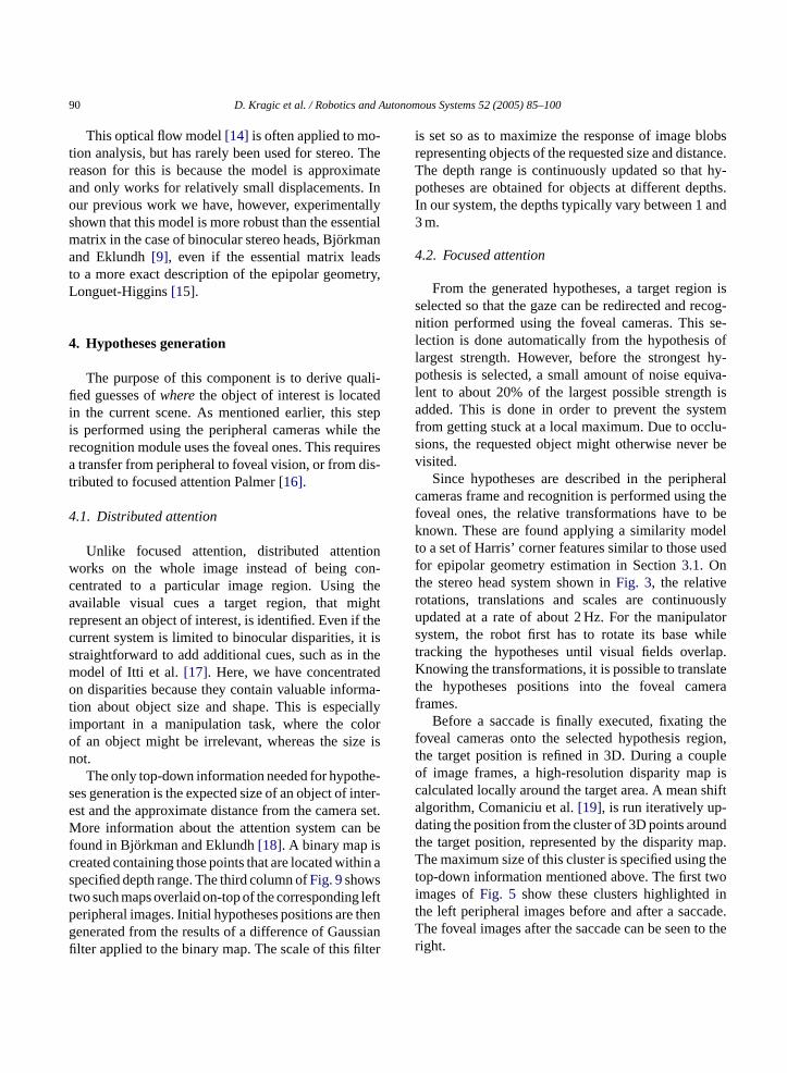
This optical flow model[14] is often applied to mo-tion analysis, but has rarely been used for stereo. Thereason for this is because the model is approximateand only works for relatively small displacements. Inour previous work we have, however, experimentallyshown that this model is more robust than the essentialmatrix in the case of binocular stereo heads, Bjorkmanand Eklundh[9], even if the essential matrix leadsto a more exact description of the epipolar geometry,Longuet-Higgins[15].
4. Hypotheses generation
The purpose of this component is to derive quali-fied guesses ofwherethe object of interest is locatedin the current scene. As mentioned earlier, this stepis performed using the peripheral cameras while therecognition module uses the foveal ones. This requiresa transfer from peripheral to foveal vision, or from dis-tributed to focused attention Palmer[16].
4.1. Distributed attention
Unlike focused attention, distributed attentionworks on the whole image instead of being con-centrated to a particular image region. Using theavailable visual cues a target region, that mightrepresent an object of interest, is identified. Even if thecurrent system is limited to binocular disparities, it iss them edo ma-t iallyi loro e isn
he-s inter-e a set.M befc hin ast leftp theng sianfi lter
is set so as to maximize the response of image blobsrepresenting objects of the requested size and distance.The depth range is continuously updated so that hy-potheses are obtained for objects at different depths.In our system, the depths typically vary between 1 and3 m.
4.2. Focused attention
From the generated hypotheses, a target region isselected so that the gaze can be redirected and recog-nition performed using the foveal cameras. This se-lection is done automatically from the hypothesis oflargest strength. However, before the strongest hy-pothesis is selected, a small amount of noise equiva-lent to about 20% of the largest possible strength isadded. This is done in order to prevent the systemfrom getting stuck at a local maximum. Due to occlu-sions, the requested object might otherwise never bevisited.
Since hypotheses are described in the peripheralcameras frame and recognition is performed using thefoveal ones, the relative transformations have to beknown. These are found applying a similarity modelto a set of Harris’ corner features similar to those usedfor epipolar geometry estimation in Section3.1. Onthe stereo head system shown inFig. 3, the relativerotations, translations and scales are continuouslyupdated at a rate of about 2 Hz. For the manipulatorsystem, the robot first has to rotate its base whilet lap.K latet eraf
thef gion,t pleo isc shifta -d undt ap.T thet twoi int ade.T to ther
traightforward to add additional cues, such as inodel of Itti et al.[17]. Here, we have concentratn disparities because they contain valuable infor
ion about object size and shape. This is especmportant in a manipulation task, where the cof an object might be irrelevant, whereas the sizot.
The only top-down information needed for hypotes generation is the expected size of an object ofst and the approximate distance from the camerore information about the attention system can
ound in Bjorkman and Eklundh[18]. A binary map isreated containing those points that are located witpecified depth range. The third column ofFig. 9showswo such maps overlaid on-top of the correspondingeripheral images. Initial hypotheses positions areenerated from the results of a difference of Gauslter applied to the binary map. The scale of this fi
racking the hypotheses until visual fields overnowing the transformations, it is possible to trans
he hypotheses positions into the foveal camrames.
Before a saccade is finally executed, fixatingoveal cameras onto the selected hypothesis rehe target position is refined in 3D. During a couf image frames, a high-resolution disparity mapalculated locally around the target area. A meanlgorithm, Comaniciu et al.[19], is run iteratively upating the position from the cluster of 3D points aro
he target position, represented by the disparity mhe maximum size of this cluster is specified using
op-down information mentioned above. The firstmages ofFig. 5 show these clusters highlightedhe left peripheral images before and after a sacche foveal images after the saccade can be seenight.

D. Kragic et al. / Robotics and Autonomous Systems 52 (2005) 85–100 91
Fig. 5. The first two images show a target region before and after a saccade (the rectangles show the foveal regions within the left peripheralcamera image) and the foveal camera images after executing a saccade are shown in the last two images.
4.3. Active search
For mobile manipulation tasks, it is important thatthe visual system is able to actively search for the ob-ject of interest. The search system includes two neces-sary components, an attentional system that provideshypotheses to where an object of interest might be lo-cated, and a recognition system that verifies whether arequested object has indeed been found, as presentedabove. Even if the attentional system works on a rela-tively wide field of view, 60◦ is still limited if alocationis completely unknown to the robot. In our system, wehave extended this range by applying an active searchstrategy, that scans the environment and records themost probable locations. Five images from such a scancan be seen on the last row ofFig. 6. The crossesindicate hypothesis positions when the robot activelysearches for and locates an orange package that is in factlocated on the table seen on the first and fourth image.
5. Manipulating known objects
If a robot is to manipulate a known object, some typeof representation is typically known in advance. Such arepresentation may include object textural and/or geo-metrical properties which are sufficient for theobject tobe located and manipulation task to be performed. Forrealistic settings, a crude information about objects lo-cation can sometimes be provided from the task level.e.g. “Bring me red cup from the dinner table”. How-ever, if the location of the object is not provided, it is upto the robot to search the scene. The following sectionsgive examples of how these problems are approachedin the current system.
5.1. Detect
If we can assume that the object is in the field of viewfrom the beginning of the task, a monocular recognition
F equest : strongesth
ig. 6. First row: hue-saliency map with orange package as rypotheses marked with crosses.
ed object, second row: peripheral disparity map, and third row

92 D. Kragic et al. / Robotics and Autonomous Systems 52 (2005) 85–100
system can be used to locate the object in the image,Zillich et al. [20].
However, when a crude information about object’scurrent position is not available, detecting a known ob-ject is not an easy task since a large number of falsepositives can be expected. Candidate locations have tobe analyzed in sequence which may be computationallytoo expensive, unless the robot has an attentional sys-tem that delivers the most likely candidate locationsfirst, using as much information about the requestedobject as possible.
A natural approach here is to employ a binoc-ular system that provides metric information as anadditional cue. Since the field of view of a typicalcamera is quite limited, binocular information canonly be extracted from those parts of the 3D scenethat are covered by both cameras’ peripheral field ofview. In order to make sure that an object of inter-est is situated in the center of each camera’s field ofview, the head is able to actively change gaze direc-tion and vergence angle, i.e. the difference in orienta-tion between the two cameras. In our system, stereobased figure-ground segmentation is intended for mo-bile robot navigation and robot arm transportation tothe vicinity of the object. More detailed informationabout an object’s pose is provided using a monocu-lar model based pose estimation and tracking, Kragic[21].
The visual front-end is responsible for delivering 3Ddata about the observed scene. Such information is ex-t s thea ager ps.T y ata andu pre-t emc -o agep per-f fored in-c im-p dgb d, ist ac-c ant,
the computational cost of these methods makes theminfeasible for our particular application which meansthat correlation based methods are typically used inpractice. Currently, we use two kinds of visual cuesfor this purpose, 3D size and hue histograms usingthe procedure described in Section4.1. These cueswere chosen since they are highly object dependentand relatively insensitive to changing lighting condi-tions, object pose and viewing direction. The imagesin Fig. 6 show examples where the orange packageis requested. The upper images illustrate the saliencymaps generated using the hue histograms of this ob-ject. From the disparity maps (second row) a numberof candidate locations are found, as shown in the lastrow.
We further use recognition to verify that a requestedobject has indeed been found. With attention and recog-nition applied in a loop, the system is able to automat-ically search the scene for a particular object, until ithas been found by the recognition system. Two recog-nition modules are available for this purpose: (i) a fea-ture based module based on Scale Invariant FeatureTransform (SIFT) features Lowe[24], and (ii) an ap-pearance based module using color histograms, Ekvallet al.[25].
Most recognition algorithms expect the consideredobject to subtend a relatively large proportion of theimages. If the object is small, it has to be approachedbefore is can be detected. Possible solution wouldbe using a eye-in-hand camera and only approacht lat-f eme ras,l pre-s fieldc vealo
5
ct,c reg-i eent eens y, ith msf ighr ore
racted using a three-step process, which includebove mentioned epipolar geometry estimation, imectification and calculation of dense disparity mahe generation of this data is done continuouslrate of 8 Hz, independently of the task at hand
sed by more high-level processes for further interation. Further information on this part of the systan be found in Bjorkman [10]. Since most methds for dense disparity estimation assume the imlanes to be parallel, image rectification has to be
ormed using the estimated epipolar geometry beisparities can be estimated. The current systemludes seven different disparity algorithms, from sle area correlation, Konolige[22] to more complicateraph-cut methods, Kolmogorov and Zabih[23]. Theenefit of using a more advanced global metho
he fact that they often lead to denser and moreurate results. However, even if density is import
he object through the manipulator, keeping the porm itself static. A more efficient solution is a systquipped with wide field as well as foveal came
ike the stereo-head system used for the exampleented here. Hypotheses are found using the wideameras, while recognition is done using the fones.
.2. Approach
Transporting the arm to the vicinity of the objeonsidering a closed-loop control system, requiresstration or computation of spatial relationship betwwo or more images. Although this problem has btudied extensively in the computer vision societas rarely been fully integrated in robotic syste
or unknown objects. One reason for this is that heal-time demand makes the problem of tracking m
D. Kragic et al. / Robotics and Autonomous Systems 52 (2005) 85–100 93
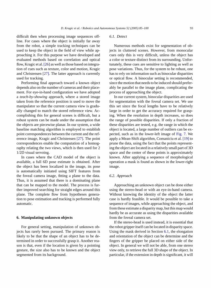
difficult then when processing image sequences off-line. For cases where the object is initially far awayfrom the robot, a simple tracking techniques can beused to keep the object in the field of view while ap-proaching it. For this purpose we have developed andevaluated methods based on correlation and opticalflow, Kragic et al.[26] as well as those based on integra-tion of cues such as texture, color and motion, Kragicand Christensen[27]. The latter approach is currentlyused for tracking.
Performing final approach toward a known objectdepends also on the number of cameras and their place-ment. For eye-in-hand configuration we have adopteda teach-by-showingapproach, where a stored imagetaken from the reference position is used to move themanipulator so that the current camera view is gradu-ally changed to match the stored reference view. Ac-complishing this for general scenes is difficult, but arobust system can be made under the assumption thatthe objects are piecewise planar. In our system, a widebaseline matching algorithm is employed to establishpoint correspondences between the current and the ref-erence image, Kragic and Christensen[27]. The pointcorrespondences enable the computation of a homog-raphy relating the two views, which is then used for 21/2D visual servoing.
In cases where the CAD model of the object isavailable, a full 6D pose estimate is obtained. Afterthe object has been localized in the image, its poseis automatically initiated using SIFT features fromt ata.T lanet fur-t thisp era-t ullya
6
ob-j on isl de-t rea-s ingg bjects
6.1. Detect
Numerous methods exist for segmentation of ob-jects in cluttered scenes. However, from monocularcues only this is very difficult, unless the object hasa color or texture distinct from its surrounding. Unfor-tunately, these cues are sensitive to lighting as well aspose variations. Thus, for the system to be robust, onehas to rely on information such as binocular disparitiesor optical flow. A binocular setting is recommended,since the motion that needs to be induced should prefer-ably be parallel to the image plane, complicating theprocess of approaching the object.
In our current system, binocular disparities are usedfor segmentation with the foveal camera set. We usethis set since the focal lengths have to be relativelylarge in order to get the accuracy required for grasp-ing. When the resolution in depth increases, so doesthe range of possible disparities. If only a fraction ofthese disparities are tested, e.g. the range in which theobject is located, a large number of outliers can be ex-pected, such as in the lower-left image ofFig. 7. Weapply a Mean-Shift algorithm, Comaniciu et al.[19] toprune the data, using the fact that the points represent-ing the object are located in a relatively small part of 3Dspace and the center of these points is approximatelyknown. After applying a sequence of morphologicaloperation a mask is found as shown in the lower-rightimage.
6
itheru era.W terc ke as , andf ouldh ilablef
l thatt ace.U na thefi theo reov . Inp ill
he foveal camera image, fitting a plane to the dhus, it is assumed that there is a dominating p
hat can be mapped to the model. The process isher improved searching for straight edges aroundlane. The complete flow from hypotheses gen
ion to pose estimation and tracking is performed futomatic.
. Manipulating unknown objects
For general setting, manipulation of unknownects has rarely been pursued. The primary reasikely to be that the shape of an object has to beermined in order to successfully grasp it. Anotheron is that, even if the location is given by a pointesture, the size also has to be known and the oegmented from its background.
.2. Approach
Approaching an unknown object can be done esing the stereo-head or with an eye-in-hand camithout knowing the identity of the object the lat
ase is hardly feasible. It would be possible to taequence of images, while approaching the objectrom these estimate a disparity map, but this map wardly be as accurate as using the disparities ava
rom the foveal camera set.If the stereo-head is used instead, it is essentia
he robot gripper itself can be located in disparity spsing the mask derived in Section6.1, the elongationd orientation of the object can be determine andngers of the gripper be placed on either side ofbject. In general we will not be able, from one steiew only, to retrieve the full 3D shape of the objectarticular, if the extension in depth is significant, it w

94 D. Kragic et al. / Robotics and Autonomous Systems 52 (2005) 85–100
Fig. 7. Left peripheral (upper left) and foveal (upper right) camera images and disparities (lower left) and segmentation (lower right) automaticallyobtained from the peripheral stereo pair.
be difficult to guarantee that the full closing grasp canbe performed. This problem can be solved by movingthe stereo-head to another location. This is a topic weintend to investigate further in the future.
7. Grasping
For active grasping, visual sensing will in generalnot suffice. One of the problems closely related to eye-in-hand configurations is the fact that when theap-proachstep is finished, the object is very close to thecamera, commonly covering the whole field of view.To retrieve features necessary for grasp planning is im-possible. One solution to this problem is to use a widefield eye-in-hand camera, together with a stand-alonemono- or stereo vision system. Our previous work hasintegrated visual information with tactile and force-torque sensing for object grasping, Kragic and Chris-tensen[28]. We have, however, realized that there is aneed for a system that is able to monitor the graspingprocess and track the pose of the object during exe-
cution. We have shown that in this way, even if therobot moves the object, grasping can successfully beperformed without the need to reinitiate the whole pro-cess. This can be done even for unknown objects wherethe Mean-Shift strategy suggested in Section6.1is ap-plied on consecutive images.
8. Experimental evaluation
As mentioned in Section3, our system is built ona number of independently running and communicat-ing modules. Since most methods used within thesemodules have been analyzed elsewhere, we will con-centrate on the integrated system as a whole, rather thananalyzing each individual method in isolation. The sys-tem should be considered as an integrated unit and itsperformance measured based on the behavior of thecomplete system. The failure of one particular moduledoes not necessarily mean that the whole system fails.For example, figure-ground segmentation might wellfail to separate two nearby objects located on a similar
D. Kragic et al. / Robotics and Autonomous Systems 52 (2005) 85–100 95
distance, but the system might still be able to initiatepose estimation after recognition.
The following properties of the system have beenevaluated, as will be described in more detail in thesections below:
• combined figure-ground segmentation based on bin-ocular disparities and monocular pose estimation,
• combined monocular Cooccurence Color Histog-rams (CCH) Chang and Krumm[29] based objectrecognition and monocular pose estimation,
• robustness of figure-ground segmentation,• robustness toward occlusions using SIFT features,• robustness of pose initialization toward rotations.
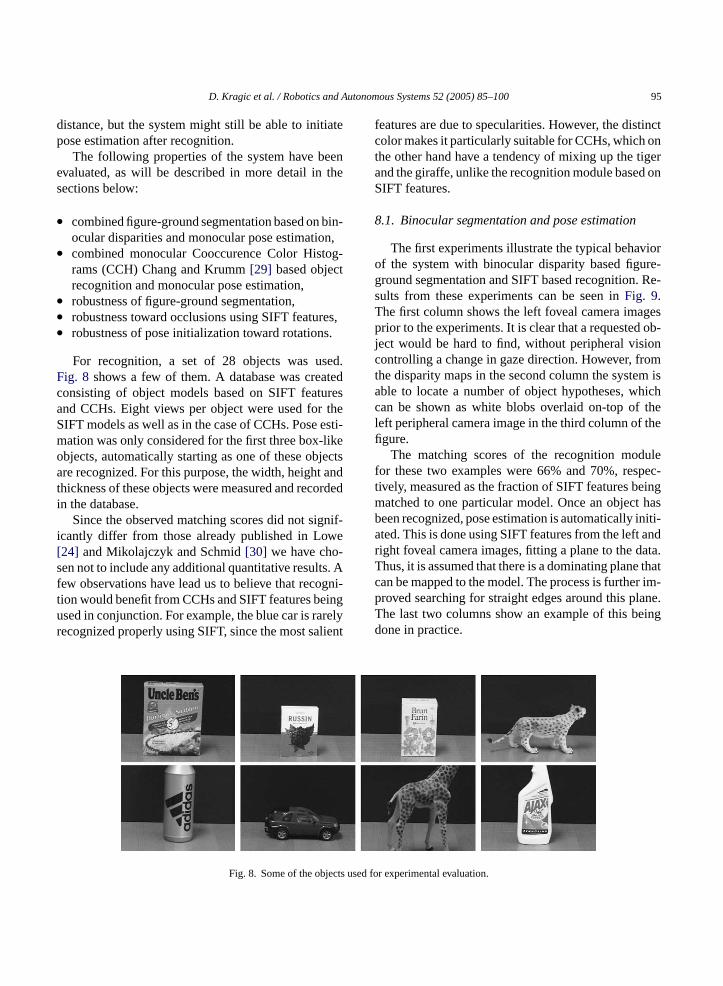
For recognition, a set of 28 objects was used.Fig. 8 shows a few of them. A database was createdconsisting of object models based on SIFT featuresand CCHs. Eight views per object were used for theSIFT models as well as in the case of CCHs. Pose esti-mation was only considered for the first three box-likeobjects, automatically starting as one of these objectsare recognized. For this purpose, the width, height andthickness of these objects were measured and recordedin the database.
Since the observed matching scores did not signif-icantly differ from those already published in Lowe[24] and Mikolajczyk and Schmid[30] we have cho-sen not to include any additional quantitative results. Afew observations have lead us to believe that recogni-t ingu relyr lient
features are due to specularities. However, the distinctcolor makes it particularly suitable for CCHs, which onthe other hand have a tendency of mixing up the tigerand the giraffe, unlike the recognition module based onSIFT features.
8.1. Binocular segmentation and pose estimation
The first experiments illustrate the typical behaviorof the system with binocular disparity based figure-ground segmentation and SIFT based recognition. Re-sults from these experiments can be seen inFig. 9.The first column shows the left foveal camera imagesprior to the experiments. It is clear that a requested ob-ject would be hard to find, without peripheral visioncontrolling a change in gaze direction. However, fromthe disparity maps in the second column the system isable to locate a number of object hypotheses, whichcan be shown as white blobs overlaid on-top of theleft peripheral camera image in the third column of thefigure.
The matching scores of the recognition modulefor these two examples were 66% and 70%, respec-tively, measured as the fraction of SIFT features beingmatched to one particular model. Once an object hasbeen recognized, pose estimation is automatically initi-ated. This is done using SIFT features from the left andright foveal camera images, fitting a plane to the data.Thus, it is assumed that there is a dominating plane thatcan be mapped to the model. The process is further im-p lane.T ingd
ts use
ion would benefit from CCHs and SIFT features besed in conjunction. For example, the blue car is raecognized properly using SIFT, since the most sa
Fig. 8. Some of the objec
roved searching for straight edges around this phe last two columns show an example of this beone in practice.
d for experimental evaluation.

96 D. Kragic et al. / Robotics and Autonomous Systems 52 (2005) 85–100
Fig. 9. An example of binocular figure-ground segmentation and pose estimation. The first column shows the foveal images before a saccadehas been issued. Disparity maps can be seen in the second column and object hypotheses in third. The last column shows the estimated pose.
8.2. Monocular CCH recognition and poseestimation
Fig. 10 shows two examples of recognition andpose estimation based on monocular CCH. Here, objectrecognition and rotation estimation serve as the initialvalues for the model based pose estimation and track-ing modules. With the incomplete pose calculated inthe recognition (first image from the left) and orienta-tion estimation step, the initial full pose is estimated(second image from the left). After that, a local fittingmethod matches lines in the image with edges of theprojected object model. The images obtained after con-vergence of the tracking scheme is shown on the right.It is important to note, that even under the incorrectinitialization of the two other rotation angles as zero,our approach is able to cope with significant deviationsfrom this assumption. This is strongly visible in the sec-
ond example where the angle around camera’sZ-axisis more than 20◦.
8.3. Robustness of disparity based figure-groundsegmentation
As mentioned in Section4, object location hypothe-ses are found slicing up the disparities into a binary mapof pixels located within a given depth range. There aresome evident disadvantages associated with such a pro-cedure. First of all, an object might be tilted and extendbeyond this range. This can be seen in the upper leftimage inFig. 11—but it does not occur in the secondimage on the same row. However, since a more accu-rate localization is found through the focused attentionprocess, a saccade is issued to the approximately samelocation. This is shown in the last two images on theupper row.
F t): (i) th er threefi
ig. 10. From object recognition to pose estimation, (from leftting iterations, (iv) the estimated pose of the object.
e output of the recognition, (ii) initial pose estimation, (iii) aft
D. Kragic et al. / Robotics and Autonomous Systems 52 (2005) 85–100 97
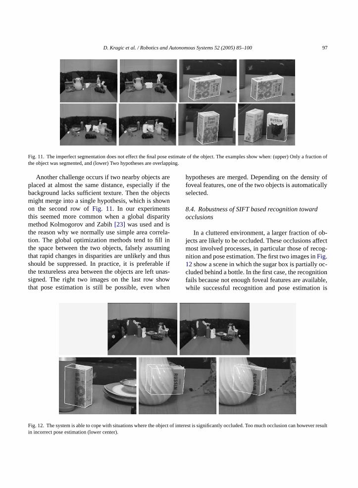
Fig. 11. The imperfect segmentation does not effect the final pose estimate of the object. The examples show when: (upper) Only a fraction ofthe object was segmented, and (lower) Two hypotheses are overlapping.
Another challenge occurs if two nearby objects areplaced at almost the same distance, especially if thebackground lacks sufficient texture. Then the objectsmight merge into a single hypothesis, which is shownon the second row ofFig. 11. In our experimentsthis seemed more common when a global disparitymethod Kolmogorov and Zabih[23] was used and isthe reason why we normally use simple area correla-tion. The global optimization methods tend to fill inthe space between the two objects, falsely assumingthat rapid changes in disparities are unlikely and thusshould be suppressed. In practice, it is preferable ifthe textureless area between the objects are left unas-signed. The right two images on the last row showthat pose estimation is still be possible, even when
hypotheses are merged. Depending on the density offoveal features, one of the two objects is automaticallyselected.
8.4. Robustness of SIFT based recognition towardocclusions
In a cluttered environment, a larger fraction of ob-jects are likely to be occluded. These occlusions affectmost involved processes, in particular those of recog-nition and pose estimation. The first two images inFig.12show a scene in which the sugar box is partially oc-cluded behind a bottle. In the first case, the recognitionfails because not enough foveal features are available,while successful recognition and pose estimation is
F bject of ever resulti
ig. 12. The system is able to cope with situations where the on incorrect pose estimation (lower center).
interest is significantly occluded. Too much occlusion can how
98 D. Kragic et al. / Robotics and Autonomous Systems 52 (2005) 85–100
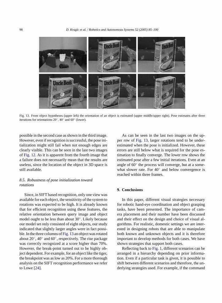
Fig. 13. From object hypotheses (upper left) the orientation of an object is estimated (upper middle/upper right). Pose estimates after threeiterations for orientations 20◦, 40◦ and 60◦ (lower).
possible in the second case as shown in the third image.However, even if recognition is successful, the pose ini-tialization might still fail when not enough edges areclearly visible. This can be seen in the last two imagesof Fig. 12. As it is apparent from the fourth image thata failure does not necessarily mean that the results areuseless, since the location of the object in 3D space isstill available.
8.5. Robustness of pose initialization towardrotations
Since, in SIFT based recognition, only one view wasavailable for each object, the sensitivity of the system torotations was expected to be high. It is already knownthat for efficient recognition using these features, therelative orientation between query image and objectmodel ought to be less than about 30◦. Likely becauseour model set only consisted of eight objects, our studyindicated that slightly larger angles were in fact possi-ble. In the three columns ofFig. 13an object was rotatedabout 20◦, 40◦ and 60◦, respectively. The rise packagewas correctly recognized at a score higher than 70%.However, the break-point turned out to be highly ob-ject dependent. For example, for an object like the tiger,the breakpoint was as low as 20%. For a more thoroughanalysis on the SIFT recognition performance we referto Lowe[24].
As can be seen in the last two images on the up-per row ofFig. 13, larger rotations tend to be under-estimated when the pose is initialized. However, theseerrors are still below what is required for the pose es-timation to finally converge. The lower row shows theestimated pose after a few initial iterations. Even at anangle of 60◦ the process will converge, but at a some-what slower rate. For 40◦ and below convergence isreached within three frames.
9. Conclusions
In this paper, different visual strategies necessaryfor robotic hand-eye coordination and object graspingtasks, have been presented. The importance of cam-era placement and their number have been discussedand their effect on the design and choice of visual al-gorithms. For realistic, domestic settings we are inter-ested in designing robots that are able to manipulateboth known and unknown objects and it is thereforeimportant to develop methods for both cases. We haveshown strategies that support both cases.
Reflecting back toFig. 1, different scenarios can bearranged in a hierarchy depending on prior informa-tion. Even if a particular task is given, it is possible toshift between different scenarios and therefore, the un-derlying strategies used. For example, if the command

D. Kragic et al. / Robotics and Autonomous Systems 52 (2005) 85–100 99
“Pick Up This Cup” is given, but the system fails toverify the existence of the cup, the execution may stillcontinue as if “Pick up The Cup” was given. A vice-versa example is if the command “Pick Up This Ob-ject” was given and the system realizes that the ob-ject is, in fact, a known box of raisins. Then, the sys-tem automatically changes the task to “Pick Up TheRaisins”. In the future, we want to develop a moreformal description for the above, in order to designa visual system framework for robotic manipulation ingeneral.
References
[1] S. Hutchinson, G. Hager, P. Corke, A tutorial on visual servocontrol, IEEE Trans. Robot. Autom. 12 (5) (1996) 651–670.
[2] D.H. Ballard, Animate vision, Artif. Intel. 48 (1) (1991) 57–86.
[3] M. Bj orkman, D. Kragic, Combination of foveal and peripheralvision for object recognition and pose estimation, Proceedingsof the IEEE International Conference on Robotics and Automa-tion, ICRA’04 5, 2004, pp. 5135–5140.
[4] S. Kim, I. Kim, I. Kweon, Robust model-based 3d object recog-nition by combining feature matching with tracking, Proceed-ings of the IEEE International Conference on Robotics andAutomation, ICRA’03, 2003, pp. 2123–2128.
[5] E. Malis, G. Chesi, R. Cipolla, 2 1/2 d Visual servoing withrespect to planar contours having complex and unknown shapes,Int. J. Robot. Res. 22 (10–11) (2003) 841–854.
[6] D. Kragic, H. Christensen, A framework for visual servoing,Proceedings of the International Conference on Computer Vi-
ct toIEEEl. 2,
hinMag.
es-nal.
[ e vi-andol-
[ ector,
[ digmau-24,
[ .
[14] H. Longuet-Higgins, The interpretation of a moving retinal im-age, Philos. Trans. R. Soc. Lond., B 208 (1980) 385–397.
[15] H. Longuet-Higgins, A computer algorithm for reconstructinga scene from two projections, Nature 293 (1981) 133–135.
[16] S.E. Palmer, Vision Science: Photons to Phenomenology, MITPress, Cambridge, MA, 1999.
[17] L. Itti, C. Koch, E. Niebur, A model of saliency-based visualattention for rapid scene analysis, IEEE Trans. Pattern Anal.Mach. Intel. 20 (11) (1998) 1254–1259.
[18] M. Bjorkman, J.-O. Eklundh, Attending, foveating and recog-nizing objects in real world scenes, Proceedings of British Ma-chine Vision Conference, BMVC’04, 2004.
[19] D. Comaniciu, V. Ramesh, P. Meer, Real-time tracking of non-rigid objects using mean shift, Proceedings of the IEEE Con-ference on Computer Vision and Pattern Recognition, CVPR2000, 2000, pp. 142–151.
[20] M. Zillich, D. Roobaert, J.O. Eklundh, A pure learning ap-proach to background-invariant object recognition using ped-agogical support vector learning, CVPR-2001, IEEE, Kauai,2001.
[21] D. Kragic, Visual servoing for manipulation: robustness and in-tegration issues, Ph.D. thesis, Computational Vision and ActivePerception Laboratory (CVAP), Royal Institute of Technology,Stockholm, Sweden, 2001.
[22] K. Konolige, Small vision systems: hardware and implemen-tation, International Symposium on Robotics Research, 1997,pp. 203–212.
[23] V. Kolmogorov, R. Zabih, Computing visual correspondencewith occlusions using graph cuts, Proceedings of the IEEEInternational Conference Computer Vision, 2001, pp. 508–515.
[24] D.G. Lowe, Object recognition from local scale-invariant fea-tures, Proceedings of the IEEE International Conference onComputer Vision (ICCV 99), 1999, pp. 1150–1157.
[25] S. Ekvall, F. Hoffmann, D. Kragic, Object recognition and posenceCon-
ineon-pp.
ationnal02,
odelCon-pp.
cur-Con-, pp.
iantnfer-
sion Systems, ICVS 2003, 2003, pp. 345–354.[7] S. Benhimane, E. Malis, Vision-based control with respe
planar and non-planar objects using a zooming camera,IEEE International Conference on Advanced Robotics, vo2003, pp. 991–996.
[8] S. Vinoski, CORBA: integrating diverser applications witdistributed heterogeneous environments, IEEE Commun.14 (2) (1997).
[9] M. Bj orkman, J.-O. Eklundh, Real-time epipolar geometrytimation of binocular stereo heads, IEEE Trans. Pattern AMach. Intel. 24 (3) (2002) 425–432.
10] M. Bjorkman, Real-time motion and stereo cues for activsual observers, Doctoral dissertation, Computational VisionActive Perception Laboratory (CVAP), Royal Inst. of Technogy, Stockholm, Sweden, 2002.
11] C. Harris, M. Stephens, A combined corner and edge detProc. Alvey Vision Conference, 1988, pp. 147–151.
12] M. Fischler, R. Bolles, Random sample consensus: a parafor model fitting with applications to image analysis andtomated cartography, Communications of the ACM, vol.1981, pp. 381–395.
13] P.J. Huber, Robust Statistics, John Willey and Sons, 1981
estimation for robotic manipulation using color cooccurrehistograms, Proceedings of the IEEE/RSJ Internationalference Intelligent Robots and Systems, IROS’03, 2003.
[26] D. Kragic, A. Miller, P. Allen, Real-time tracking meets onlgrasp planning, Proceedings of the IEEE International Cference on Robotics and Automation, ICRA’01 3, 2001,2460–2465.
[27] D. Kragic, H. Christensen, Weak models and cue integrfor real-time tracking, Proceedings of the IEEE InternatioConference on Robotics and Automation, ICRA’02 3, 20pp. 3044–3049.
[28] D. Kragic, H. Christensen, Confluence of parameters in mbased tracking, Proceedings of the IEEE Internationalference on Robotics and Automation, ICRA’03 3, 2003a,3485–3490.
[29] P. Chang, J. Krumm, Object recognition with color coocrence histograms, Proceedings of the IEEE Internationalference Computer Vision and Pattern Recognition, 1999498–504.
[30] K. Mikolajczyk, C. Schmid, Indexing based on scale invarinterest points, Proceedings of the IEEE International Coence Computer Vision, ICCV’01, 2001, pp. 525–531.

100 D. Kragic et al. / Robotics and Autonomous Systems 52 (2005) 85–100
Danica Kragic is an assistant professor at the Computational Visionand Active Perception Laboratory at the Department of NumericalAnalysis and Computer Science at the Royal Institute of Technology,Stockholm, Sweden. She received the MS degree in mechanical en-gineering from the Technical University of Rijeka, Croatia, in 1995and PhD degree in computer science from the Royal Institute of Tech-nology, Stockholm, Sweden. Her research interest include computervision, learning by demonstration, visual servoing, human-machinecollaboration and path planning.
Martenrten Bj orkman received in a PhD in computer vision atKTH in Stockholm, Sweden in 2002. Between 1994 and 1997 hewas employed by Mentor Graphics. He is currently active as a post-doc within the EC sponsored project MobVis. His primary researchinterests are stereo vision, cognitive vision systems and image basedrendering.
Henrik I.Christensen is a chaired professor of computer science andthe director of the Centre for Autonomous Systems at the SwedishRoyal Institute of Technology, Stockholm, Sweden. He is also the co-ordinator of the EU network EURON. He does research on systemsintegration, mapping and sensory fusion. He has published morethan 190 contributions on vision, AI and robotics. He serves on
the editorial board of IJRR, Autonomous Robots, IJPRAI and AIMagazine.
Jan-Olof Eklundh graduated in mathematics at Stockholm Univer-sity, 1970. He then joined the newly formed Laboratory for ImageAnalysis at the National Defence Research Institute, Stockholm, andspent 1977-1979 at the Computer Vision Laboratory, University ofMaryland. In 1982 he became associate professor at KTH wherehe founded the Computer Vision and Active Perception Laboratory,CVAP. In 1996 he initiated the Center for Autonomous Systems,in which CVAP is now a key partner. 1986 he became professor incomputer science and in 1995 Dean of the School of Electrical Engi-neering and Information Technology at KTH. His research interestscover a broad range of topics in computational vision, image pro-cessing, and robotics, especially active visual machine perceptionwith relations to human vision, analysis of shape and geometry andmotion, behavioral aspects of perception, and perceptually guidedautonomous systems. He is and has been on the editorial boards ofseveral journals, including IEEE PAMI, IJCV, CVIU and IVC andchaired ICCV 1990 and ECCV 1994. Professor Eklundh is a mem-ber of the Royal Swedish Academy of Science, the Royal DanishAcademy of Sciences and Letters and the Royal Swedish Academyof Engineering Science.